2017-18 malla reddy engineering college b.tech. …
TRANSCRIPT
2017-18
Onwards
(MR-17)
MALLA REDDY ENGINEERING COLLEGE
(Autonomous)
B.Tech.
III Semester
Code: 70308
KINEMATICS OF MACHINES L T P
Credits: 3 2 2 -
Prerequisites: Engineering Mechanics & Engineering Graphics
Course Objectives:
The objective of this subject is to provide basic concept of Mechanisms used in different machine elements like cams, gears and other power transmitting elements.
MODULE I: Mechanisms & Machines 10 Periods
Mechanisms: Elements or Links, Classification, Rigid Link, flexible and fluid link, Types of
kinematic pairs, sliding, turning, rolling, screw and spherical pairs, lower and higher pairs, closed
and open pairs, constrained motion, completely, partially or successfully constrained and
incompletely constrained.
Machines: Mechanism and machines, classification of machines, kinematic chain, inversion of
mechanisms, inversions of quadratic cycle chain, single and double slider crank chains.
MODULE II: Straight Line Motion Mechanisms, Steering Mechanisms &
Hooke’s Joint
10 Periods
Straight Line Motion Mechanisms: Exact and approximate copiers and generated types
Peaucellier, Hart and Scott Russel, Grasshopper, Watt T.Chebicheff and Robert Mechanisms and
straight line motion, Pantograph.
Steering Mechanisms: Conditions for correct steering, Davis Steering gear, Ackerman’s steering
gear mechanisms, velocity ratio. Hooke’s Joint – Single and double Hooke’s joint, Universal
coupling application problems.
MODULE III: Kinematics & Plane motion of body 10 Periods
A: Kinematics: Velocity and acceleration - Motion of link in machine - Determination of Velocity
and acceleration diagrams - Graphical method - Application of relative velocity method four bar
chain. Analysis of Mechanisms: Analysis of slider crank chain for displacement, velocity and
acceleration of slider - Acceleration diagram for a given mechanism, Kleins construction, Coriolis
acceleration, determination of Coriolis component of acceleration.
B: Plane motion of body: Instantaneous centre of rotation, centroids and axodes - relative motion
between two bodies - Three centres in line theorem - Graphical determination of instantaneous
centre, diagrams for simple mechanisms and determination of angular velocity of points and links.
MODULE IV: Cams & Analysis of Motion of Followers 09 Periods
Cams: Definitions of cam and followers, their uses, types of followers and cams, terminology.
Types of follower motion - Uniform velocity, Simple harmonic motion and uniform acceleration.
Maximum velocity and maximum acceleration during outward and return strokes in the above
three cases.
Analysis of motion of followers: Roller follower circular cam with straight, concave and convex
flanks.

MODULE V: Gears & Gear Trains 09 Periods
Gears: Higher pairs, friction wheels and toothed gears, types, law of gearing, condition for
constant velocity ratio for transmission of motion, Forms of teeth: cycloidal and involute profiles.
Velocity of sliding phenomena of interferences, Methods of interference. Condition for minimum
number of teeth to avoid interference, expressions for arc of contact and path of contact -
Introduction to Helical, Bevel and worm gearing.
Gear Trains: Introduction - Train value - Types - Simple and reverted wheel train, Epicyclic gear
train. Methods of finding train value or velocity ratio - Epicyclic gear trains. Selection of gear box- Differential gear for automobiles.
TEXT BOOKS
1. Thomas Bevan “Theory of Machines”, CBS Publishers, 3rd edition, 2005
2. S.S.Rattan “Theory of Machines and Mechanisms”, Tata McGraw Hill Publishers, 4th
edition, 2014.
REFERENCES
1. Shiegley “The Theory of Machines” , Oxford University Press, 5th edition, 2017.
2. JS Rao and RV Dukkipati, “Mechanism and Machine Theory”, New Age International Publishers, 2nd edition, 1992.
3. R.K Bansal “Theory of Machines”, Laxmi Publication, 4th edition, 2006
4. R.S. Khurmi and J K Gupta“Theory of Machines”, S Chand Publisher, 14th edition, 2008.
5. B.V. R. Gupta, “Theory of Machines”, I. K. International Publishers, 2nd edition, 2011
E - RESOURCES
1. www.umt.fme.vutbr.cz/~ruja/vyuka/kinematics/LectureNotes.pdf.
2. ebooks.library.cornell.edu/k/kmoddl/pdf/016_002.pdf
3. www.springer.com/la/book/9789400711556
4. tps://www.elsevier.com/journals/mechanism-and-machine-theory/0094-114X?...
5. www.nptelvideos.in/2012/12/kinematics-of-machines.html
6. nptel.ac.in/courses/112104121/16
Course Outcomes
At the end of the course, students will be able to
1. Understand different kinematic links and pairs used in mechanisms.
2. Understand different mechanisms.
3. Understand various concepts of mechanisms like straight line motion mechanisms,
steering gear mechanisms and the importance of universal (Hooke’s) joint. 4. Practice velocity, acceleration diagram of various mechanism. 5. Understand various motions of cam and follower and belt and rope drives.

KINEMATICS OF MACHINES
LECTURE NOTES
UNIT – I&II
Link or Element :
A link is a resistant body or assembly of resistant bodies, which constitute part or parts of a machine , connecting other parts which have motion , relative to it. A link may consist of a number of parts connected in such a way that they form one unit and have no motion relative to each other eg. Piston , piston rod and cross head of a steam engine constitute one unit and will be considered as one link. Similarly the crank pin, crank webs, crankshaft, flywheel etc constitute another link known as a crank. On the other hand crosshead, connecting rod, crank and frame of a steam engine are other links.
In fig. Link 1 -> fixed link link 3 -> connecting rod
link 2 -> crank
link 4 -> slider Single slider crank mechanism

Types of links :
Classification I : Rigid link is one which does not undergo any deformation while transmitting motion. In the real sense, rigid links do not exist. However ,as the deformation of connecting rod ,crank etc of a steam or internal combustion engine is not appreciable they can be considered as rigid. Flexible link is one which while transmitting motion is partly deformed in a manner not to affect transmission of motion. Thus it transmits motion in one direction only so as to pull or push e.g. belt.
Fluid link is formed by having fluid in a receptacle and the motion is transmitted through the fluid by pressure or by compression only as in a hydraulic press.
Classification II :
. Binary link: Link which is connected to other links at two points. (Fig.a)
Ternary link: Link which is connected to other links at three points. (Fig. b) Quaternary link: Link which is connected to other links at four points. (Fig c)
Joint and types of Joint: A point which connects two links is called joint There are three types of joints .
Binary Joint : If any joint connects two links then it is called binary joint. In fig. joint A is connected to two links 1 and 2
1 A
2
Ternary Joint : If any joint connects three links then it is called ternary joint. In fig. Joint B is connected to links 1,2&3
2 3
B

1
Quaternary Joint : If any joint connects four links then it is called quaternary joint. In fig. joint C is connected to links 1,2,3 &4
2 3
C 1 4
Kinematic pair : It is a joint of two links having relative motion between them.
(2,3) 2 3
(3,4)
1 (1,2) 4
(1,4)
In a slider crank mechanism as shown , fixed link 1 and crank 2 form one pair , crank2 and connecting rod 3 form another pair , connecting rod 3 and slider 4 form another pair and finally
Classification of Kinematic pairs : A kinematic pair is classified according to the following considerations
a) Type of contact b) type of relative motion c)type of mechanical constrraint. a)According to Type of Contact : According to this the are two types of pairs.
1.Lower pairs : A pair having surface or area contact between the members is known as a lower pair. The contact surfaces of the two links are similar.
E.g. Nut turning on a screw, shaft rotating in a bearing ,all pairs of s slider crrank mechanism,
universal joint etc
2.Higher Pairs: When a pair has a point or line contact between the links , it is known as higher pair. The contact surfaces of the two links are dissimilar.
E.g. Wheel rolling on a surface, cam and follower pair, tooth gears, ball and roller bearings etc
b)According to Type of relative motion : according to this ,there are five types off pairs.
1.Sliding Pair : If two links have a sliding motion relative to each other , they form a sliding pair
E.g. A rectangular rod in a rectanguular hole in a prism
2. Turning pair : When one link has a turning or revolving motion relative to the other , they constitutee a turning or revolving pair. E.g. A circular shaft revolving insside a bearing is a turning pair,
All pairs except the slider and guide pair are turning pairs in a single slider crank mechanism

3. Rolling pair : When the links of a pair have a rolling motion relative to each other, they form a
rolling pair, e.g. A rolling pulley over a belt, a ball and rolling bearings etc . In a ball bearing , the ball and the shaft constitute one rolling pair where as the a ball and the beariing is the second rolling pair.
4. Screw pair or helical pair : Iff two mating links have a
turning as well as sliding motion between them, they form a screw pair. This is achieved by cutting matching threaads on the two link. The lead screw and the nut of a lathe, a bolt and nut are screw pairs.
5. Spherical Pair : When one link in the form of a sphere turns inside a fixed linkk, it is a spherical
E.g. The a ball and socket joint
c)According to Nature of mechanical constraint : there are two types
1.Closed pair : when the elements of a pair are held together mechanically , it is known as a closed pair. The contact between the two can be broken only by destruction of at least one of the members. All the lower pairs and some of the higher pairs are closed pairs.

2. Unclosed pair(Open Pair) : Whhen two links of a pair are in contact either due to force of gravity or some spring action they constitute an unclosed pair. In this , the links are not held together mechhanically eg. Cam and follower pair
Kinematic Chain: A kinematic chhain is an assembly of links in which the relativve motions of the links is possible and the motion of each relative to the others is definite.
If the links are connected in such a way that no motion is possible, it results in a locked chain or structure.
If each link is assumed to form two pairs with two adjacent links, then the relation between the number of pairs ( p ) forming a kinematic chain and the number of links ( l ) may be expressed in the form of an equation :
If each link is assumed to form two pairs with two adjacent links, then the relation between the number of pairs ( p ) forming a kinematic chain and the number of links ( l ) may be expressed in the form of an equation :
The equations (i) and (ii) aree applicable only to kinematic chains, in which lower pairs are used. These equations may also be applied to kinematic chains, in which higgher pairs are used. In that case each higheer pair may be taken as equivalent to two lower pairs with an additional element or link.
Mechanism or Linkage :
When any one link is fixed , the kinematic chain becomes a mechanism

Slider crank and four bar mechanisms
If, for a particular position of a link of the chain, the positions of each of the other links of the chain can not be predicted, thhen it is called as unconstrained kinematic chain and it is not mechanism.
Difference between mechanism and machine
Mechanism Machine
1.A mechanism is an assemblage of links, the 1. A machine is an assemblagee of links having
motion to one of them produccing definite relative motion and capable of transforming
motions of others. available energy in to certain useful work. 2. A mechanism is not necessarily a machine. It 2.A machine is constituted of a mechanism or a
is meant to produce definite motion between number of mechanisms meant for transmitting
various links constituting it. energy to do useful work
3. A machine is a practical devvelopment of any
3. A Mechanism is a part of a machine mechanism
e.g. steam engine
e.g. a watch , wiper mechanism
There are three types of constrained motions

a. Completely constrained motion: It is one in which the motion takes place in a definite direction.
e.g. a rectangular bar moving in a rectangular hole. And a shaft with collars at each end rotating in a round hole.
b. Incompletely constrained motion : If the links are so connected that motion can take place in more than one direction, it is called incompletely constrained motion. A
Eg. A circular bar moving in a round hole because the bar can rotate or reciprocate , both motions being independent of one another.
c. Partially constrained motion (Successfully Constrained motion ): When the constrained motion is not completed by itself but by some other means(ie by applying some external force), it is partially constrained or successfully constrained motion. Eg. A foot step bearing and rotor of a vertical turbine.
Grublers Criterion: Let n = total number of links in a mechanism
F is degrees of freedom
P1 is the no. of pairs having one degree of freedom
P2 is the no. of pairs having two degrees of freedom
Total number of movable links = n-1
No of degrees of freedom of (n-1) movable links is 3(n-1)
Each pair having one dof impose 2 restrictions .

So no of restrictions because of P1 pairs are 2P1
Each pair having two dof imposse 1 restrictions .
So no of restrictions because of P2 pairs are 1P2
Hence , total degrees of freedom for mechanism = 3(n-1)- 2P1-1P2 This equation is known as Grueeblers criterion.
If all the pairs are of one dof , thhen P2=0
then dof =3(n-1)- 2P1 Dof =0 means there is no relaative motion between the links and it is called locked chain or structure
Dof=1 means one input is necesssary for definite motion of other links. Dof=2 means two inputs are neccessary for definite motion of other links.
Dof = -1 then the mechanism is called super structure.
eg 1.
dof =3(n-1)- 2P1
Here, n = 3, P1= 3
F = 3(3-1)-2(3) = 0
Eg 2.
dof =3(n-1)- 2P1
Here, n = 4, P1= 4
F = 3(4-1)-2(4) = 1
F = 3(n-1)-2l-h Here, n2 = 4, n3 =2, n = 6, l = 7 andd h = 0. F = 3(6-1)-2(7) = 1
I.e., one input to any one link will result in definite motion of all the links.
Crank : Any link which can rotatte about hinge point completely is called crankk . In fig. link 1 rotates completely about hinge poinnt O so it is crank
O

Lever or Rocker : Any link whicch oscillates between two extreme positions is called a lever or
rocker . In fig. link 1 can only oscilllate between O O1 and O O
11 so it is rocker or leever
O1
O111
O Inversion
A mechanism is one in which one of the links of a kinematic chain is fixed. Different mechanisms can be obtainedd by fixing different links of the same kinematic chain. These are called as inversions of the mechanism.
By changing the fixed link, the number of mechanisms which can be obtainned is equal to the number of links. Excepting the original mechanism, all other mechanisms will be known as inversions of original mecchanism. The inversion of a mechanism does not change the motion of its links relative to each other.
Inversions four bar kinematic chain ( quadric cycle kinematic chain) :
There are four inversions of four bar chain
i) when link adjacent to the shorttest link is fixed (ie link ‘l’ or ‘q’ ) , then the shoortest link (ie link ‘s’ ) act as crank and the link parallel to the shortest link ( ie link ‘p’ ) act as lever or rocker . This mechanism is called crank rocker mechanism (fig a and fig b)

ii) when shortest link is fixed (ie link ‘s’) , then the links adjacent to the shortest link (ie link ‘l’and link ‘q’ ) act as cranks. This mechanism is called double crank mechanism (fig c ) iii) when link opposite to the shortest link is fixed (ie link ‘p’ ) , then the the links adjacent to the shortest link (ie link ‘l’and link ‘q’ ) act as levers or rocker . This mechanism is called douoble rocker mechanism (fig d)
Grashof Law states that a four bar mechanism has atleast one revolving link if the sum of the lengths of the largest and the shortest links is less than the sum of lengths of the other two links.
For four bar mechanism as shown , c+d<a+b
Applications :
1. Beam Engine A part of the mechanism of a beam engine (also known as crank and lever mechanism) which consists of four links, is shown in Fig.. In this mechanism, when the crank2 rotates about the fixed centre O, the lever 4 oscillates about a fixed centre. The end of the lever is connected to a piston rod which reciprocates due to the rotation of the crank. In other words, the purpose of this mechanism is to convert rotary motion into reciprocating motion

2. Parallel Crank Mechanism :
In this mechanism, the links O2B and O4C (having equal length) act as cranks and are
connected to the respective wheels.
The link BC acts as a coupling rod and the link O2O4 is fixed in order to maintain a constant centre to entre distance between them. This mechanism is meant for transmitting rotary motion from one wheel to the other wheel.
3.Watt straigtline motion mechanism: It is a crossed four bar chain mechanism and was used by Watt for his early steam engines to guide the piston rod in a cylinder to have an approximate straight line motion. When links AB and CD oscilates then , the point P traces approximate straight line.
Inversions and applications of single slider crank kinematic chain Slider crank chain: This is a kinematic chain having four links. It has one sliding pair and three turning pairs.
Link 2 has rotary motion and is called crank. Link 3 has got combined rotary and reciprocating
motion and is called connecting rod. Link 4 has reciprocating motion and is called slider. This mechanism is used to convert rotary motion to reciprocating and vice versa.
Inversions of slider crank chain: Inversions of slider crank mechanism is obtained by fixing links 2, 3 and 4.
(a) Link 1 is fixed.
(b) crank fixed

(c) connecting rod fixed
(d) slider fixed
Applications :
1. Rotary engine (Gnome Engine)
It consists of seven cylinders in one plane and all revolves about fixed centre D, as shown in Fig., while the crank (link 2) is fixed. In this mechanism, when the connecting rod (link 3)
rotates, the piston (link 4) reciprocates inside the cylinders forming link 1.
2.Oscillating cylinder engine:
The arrangement of oscillating cylinder engine mechanism, as shown in Fig. , is used to convert reciprocating motion into rotary motion.
In this mechanism, the link 3 forming the turning pair is fixed. When the crank (link 1) rotates, the piston attached to piston rod (link 4) reciprocates and the cylinder (link 3) oscillates about a pin pivoted to the fixed link.

3.Hand Pump: crank (link 2) rotates, the connecting rod (link 3) oscillates about a pin pivoted to the fixed link 4 at A and the piston attached to the piston rod (liink 1) reciprocates.
The duplex pump which is used to supply feed water to boilers have two pistons attached to link 1, as shown in Fig
4.Whitwoth quick return motion mechanism :
This mechanism is mostly used in shaping and slotting machines. In this mechanism, the link CD (link 2) forming thee turning pair is fixed, as shown in Fig. Time taken during the cutting stroke (or forward stroke) is more than the time taken during the return stroke. In other words, the mean speed of the ram during cuttiing stroke is less than the mean speed duringg the return stroke. The ratio between the time taken during the cutting and return strokes is given by
5. Crank and Slotted Lever Mechanism: This mechanism is mostly used in shaping machines and slotting machines
In this mechanism, the link AC (i.e. link 3) forming the turning pair is fixed, as shown in Fig. The link 3 correspondds to the connecting rod of a reciprocating steeam engine. The driving crank CB revolves with uniform angular speed about the fixed centre C. A sliding block attached to the crank pin at B slides along the slotted bar APP and thus causes AP to oscillate about the pivoted point A. A short link PR transmits the motion from AP to the ram which carries the tool and reciprocates along the line of stroke R1R2. The line of stroke of the ram (i.e. R1R2)) is perpendicular to AC produced

In the extreme positions, APP 1 and AP 2 are tangential to the circle and the cutting tool is at the end of the stroke. The forward or cutting stroke occurs when the crank rotates from the position CB 1 to CB 2 (or through an angle β) in the clockwise direction. The return stroke occurs when the crank rotaates from the position CB2 to CB1 (or throughh angle α) in the clockwise direction. Since thhe crank has uniform angular speed, therefore,
AC= Length of fixed link
AP1 = Slotted Lever Length
CB1= Crank Length
Tan (90 - α/2) = QP1/AP1
Cos (α/2) = B1C/AC
Stroke Length =2(QP1)
Inversions and applications of double slider crank kinematic chain :
1.Elliptical trammel. This is a device which is used for generating an elliptical profile

When the sliders reciprocate , the point C traces elliptical path. Let (x,y) be the coordinates of the point C x= BC cos θ => cosθ =
y=AC sinθ => sin θ = 1
1
This is the equation for ellipse. Hennce the point C traces elliptical path. 2.Scotch Yoke Mechanism: This mechanism is used for converrting rotary motion into a reciprocating motion. The inversion is obtained by fixing either the link 1 or link 3. In Fig. link 1 is fixed. In this mechhanism, when the link 2 (which corresponds to crankk) rotates about B as centre, the link 4 (which corresponds to a frame) reciprocates. The fixed link 1 guides the frame.
3. Oldham Coupling:
An oldham's coupling is used for connecting two parallel shafts whose axxes are at a small distance apart. The shafts arre coupled in such a way that if one shaft rotatees, the other shaft also rotates at the same speed. This inversion is obtained by fixing the linnk 2, as shown in Fig. .
If the distance between the axes of the shafts is constant, the centre of inntermediate piece will describe a circle of radius equal to the distance between the axes of the two shafts.
Therefore, the maximum sliding speed of each tongue along its slot is equal to the peripheral velocity of the centre of the disc along its circular path.
Let ω = Angular velocity of each shaft in rad/s, and r = Distance between the axes of the shafts in metres. Maximum sliding speed of each tongue (in m/s), v = ω.r

Pantograph:
A pantograph is an instrument used to reproduce to an enlarged or a reduced scale and as
exactly as possible the path described by a given point. It consists of a jointed parallelogram
ABCD as shown in Fig. It is made up of bars connected by turning pairs. The bars BA and BC are
extended to O and E respectively, such that OA/OB = AD/BE
Thus, for all relative positions of the bars, the triangles OAD and OBE are similar and the points
O, D and E are in one straight line. It may be proved that point E traces out the same path as
described by point D.
From similar triangles OAD and OBE, we find that
OD/OE = AD/BE
Let point O be fixed and the points D and E move to some new positions D and E . Then
OD/OE = OD /OE
A little consideration will show that the straight line DD is parallel to the straight line EE .
Hence, if O is fixed to the frame of a machine by means of a turning pair and D is attached to a
point in the machine which has rectilinear motion relative to the frame, then E will also trace out a
straight line path. Similarly, if E is constrained to move in a straight line, then D will trace out a
straight line Parallel to the former.
A pantograph is mostly used for the reproduction of plane areas and figures such as maps,
plans etc., on enlarged or reduced scales. It is, sometimes, used as an indicator rig in order to
reproduce to a small scale the displacement of the crosshead and therefore of the piston of a
reciprocating steam engine. It is also used to guide cutting tools. A modified form of pantograph
is used to collect power at the top of an electric locomotive.
Pantograph
Universal or Hooke’s Joint :
A Hooke’s joint is used to connect two shafts, which are intersecting at a small angle, as shown in Fig The end of each shaft is forked to U-type and each fork provides two bearings

for the arms of a cross. The arms of the cross are perpendicular to each other. The motion is
transmitted from the driving shaft to driven shaft through a cross. The inclination of the two shafts
may be constant, but in actual practice it varies, when the motion is transmitted. The main application
of the Universal or Hooke’s joint is found in the transmission from the gear box to the differential or
back axle of the automobiles. It is also used for transmission of power to different spindles of
multiple drilling machine. It is also used as a knee joint in milling machines.
In case of automobiles, we use two Hooke’s joints one at each end of the propeller shaft, connecting
the gear box on one end and the differential on the other end. The top and front views connecting the
two shafts by a universal joint are shown in Fig.. Let the initial position of the cross be such that both
arms lie in the plane of the paper in front view, while the arm AB attached to the driving shaft lies in
the plane containing the axes of the two shafts. Let the driving shaft rotates through an angle θ, so that
the arm AB moves in a circle to a new position A1 B1 as shown in front view. A little consideration
will show that the arm CD will also move in a circle of the same size. This circle when projected in
the plane of paper appears to be an ellipse. Therefore the arm CD takes new position C1D1 on the
ellipse, at an angle θ. But the true angle must be on the circular path. To find the true angle, project the
point C1 horizontally to intersect the circle at C2. Therefore the angle COC2 (equal to φ) is the true
angle turned by the driven shaft. Thus when the driving shaft turns through an angle θ, the driven shaft
turns through an angle φ. It may be noted that it is not necessary that φ may be greater than θ or less
than θ. At a particular point, it may be equal to θ.
The relation between angular displacements of driving and driven is given from above diagram
tan θ cos α tanϕ
Maximum and Minimum Speeds of Driven Shaft : 1. For one complete revolution of the driven shaft, there are two points i.e. at 0° and 180° as shown by points 1 and 2 in Fig. 9.20, where the speed of the driven shaft is maximum and there are two points i.e. at 90° and 270° as shown by point 3 and 4 where the speed of the driven shaft is minimum. 2. Since there are two maximum and two minimum speeds of the driven shaft, therefore there are fourpoints when the speeds of the driven and driver shaft are same. This is shown by points, 5,6,7 and 8 in Fig. 3. Since the angular velocity of the driving shaft is usually constant, therefore it is presented by a circle of radius ω. The driven shaft has a variation in angular velocity, the maximum value being

ω/cos α and minimum value is ω cos α. Thus it is represented by an ellipse of semi-major axis ω/cos α and semi-minor axis ω cos α, as shown in Fig.
ω 2 cosα
ω 1− sin2 α sicos2 θ
1
The realation between driving and driven shaft angular velocities are
ω
(i) if 2 1 then
ω1
tan θ ∓ cosα
ω
(ii) if 2 is min imum
ω1 ω
2 cosα
(iii) if ω2
is maximum
ω1
ω2
1
ω1 cosα
For maximum angular acceleration of driven shaft , the condition is
cos2θ
2sin2 α
2 − 2sin2 α

UNIT – III
VELOCITY ANALYSIS
Absolute velocity: Velocity of a point with respect to a fixed point (zero velocity point).
Relative velocity: Velocity of a point with respect to another point ‘x’
Vba = Vab Equal in magnitude but opposite in direction
Vb Absolute velocity is velocity of B with
respect to O4 (fixed point, zero velocity point)
Note: Capital letters are used for configuration diagram. Small letters are used for velocity vector diagram.
1

Velocity Vector :
Velocity Line of action Direction magnitude
Vao2 (o2a ) Perpendicular to OA through ‘o’ (ωO2A x O2A)
o2
Vao2
a
Velocity analysis of any mechanism can be carried by various methods.
1. By graphical method
2. By relative velocity method
3. By instantaneous method
Graphical Method
The following points are to be considered while solving problems by this method.
1. Draw the configuration design to a suitable scale.
2. Locate all fixed point in a mechanism as a common point in velocity diagram.
3. Choose a suitable scale for the vector diagram velocity.
4. The velocity vector of each rotating link is r to the link.
5. Velocity of each link in mechanism has both magnitude and direction. Start from a
point whose magnitude and direction is known.
6. The points of the velocity diagram are indicated by small letters.
2

3

Velocity of Rubbing:
Two links of a mechanism having turning point will be connected by pins. When the links are motion they rub against pin surface. The velocity of rubbing of pins depends on the angular velocity of links relative to each other as well as direction.
For example: In a four bar mechanism we have pins at points A, B, C and D.
Vra = ωab x ratios of pin A (rpa)
+ sign is used ωab is CW and Wbc is CCW i.e. when angular velocities are in
opposite directions use + sign when angular velocities are in some directions use
-ve sign.
Vrb = (ωab + ωbc) radius rpb
VrC = (ωbc + ωcd) radius rpc
VrD = ωcd rpd
Instantaneous Method
To explain instantaneous centre let us consider a plane body P having a non-linear motion relative to another body q consider two points A and B on body P having velocities
as Va and Vb respectively in the direction shown.
If a line is drawn r to Va, at A the body can be imagined to rotate about some point
on the line. Thirdly, centre of rotation of the body also lies on a line r to the direction of
Vb at B. If the intersection of the two lines is at I, the body P will be rotating about I at that instant. The point I is known as the instantaneous centre of rotation for the body P. The position of instantaneous centre changes with the motion of the body.
In case of the r lines drawn from A and B meet outside the body P as shown in Fig 2.
4

If the direction of Va and Vb are parallel to the r at A and B met at ∞. This is the case
when the body has linear motion
Number of Instantaneous Centers
The number of instantaneous centers in a mechanism depends upon number of links. If N is the number of instantaneous centers and n is the number of links.
Types of Instantaneous Centers
There are three types of instantaneous centers namely fixed, permanent and neither fixed nor permanent.
Example: Four bar mechanism. n = 4.
Fixed instantaneous center I12, I14
Permanent instantaneous center I23, I34
Neither fixed nor permanent instantaneous center I13, I24
Arnold Kennedy theorem of three centers:5

STATEMENT: If three bodies have motion relative to each other, their instantaneous centers should lie in a straight line.
Consider a three link mechanism with link 1 being fixed link 2 rotating about I12 and
link 3 rotating about I13. Hence, I12 and I13 are the instantaneous centers for link 2 and
link 3. Let us assume that instantaneous center of link 2 and 3 be at point A i.e. I23. Point A is a coincident point on link 2 and link 3.
Considering A on link 2, velocity of A with respect to I12 will be a vector VA2 r to
link A I12. Similarly for point A on link 3, velocity of A with respect to I13 will be r to A
I13. It is seen that velocity vector of VA2 and VA3 are in different directions which is impossible. Hence, the instantaneous center of the two links cannot be at the assumed position.
It can be seen that when I23 lies on the line joining I12 and I13 the VA2 and VA3 will
be same in magnitude and direction. Hence, for the three links to be in relative motion all the three centers should lie in a same straight line.
Steps to locate instantaneous centers:
Step 1: Draw the configuration diagram.
Step2: Identify the number of instantaneous centers
Step 3: Identify the instantaneous centers by circle diagram.
Step 4: Locate all the instantaneous centers by making use of Kennedy’s theorem.
6

Eg :A slider crank mechanism has lengths of crank and connecting rod equal to 200
mm and 200 mm respectively locate all the instantaneous centers of the mechanism
for the position of the crank when it has turned through 30o
from IOC. Also find velocity of slider and angular velocity of connecting rod if crank rotates at 40 rad/sec.
Step 1: Draw configuration diagram to a suitable scale.
Step 2: Determine the number of links in the mechanism and find number of instantaneous centers.
Step 3: Identify instantaneous centers.
O Suit it is a 4-bar link the resulting figure will be a square.
Locate fixed and permanent instantaneous centers. To locate
neither fixed nor permanent instantaneous centers use Kennedy’s three
centers theorem
7

KLEIN’S Construction:
This method helps us to draw the velocity and acceleration diagrams on the construction diagram itself. The crank of the configuration diagram represents the velocity and acceleration line of the moving end (crank).
To draw the velocity vector diagram:
Link OA represents the velocity vector of A with respect to O.
Voa = oa = ω r = ω OA.
Draw a line perpendicular at O, extend the line BA to meet this perpendicular line at b. oab is the velocity vector diagram rotated through 90º opposite to the rotation of the crank.
Acceleration diagram:
The line representing Crank OA represents the acceleration of A with respect to O. To draw the acceleration diagram follow the steps given below.
8

Draw a circle wiith OA as radius and A as centre.
Draw another cirrcle with AB as diameter.
The two circles intersect each other at two points C and D.
Join C and D to meet OB at b1 and AB at E.
O1,a1,ba1and b1 is the required acceleration diagram rotated through 180º.
9

KINEMATICS OF MACHINES
UNIT - III ACCELERATION ANALYSIS
Acceleration Analysis :
Rate of change of velocity is acceleration. A change in velocity requires any
one of the following conditions to be fulfilled:
O Change in magnitude only
O Change in direction only
O Change in both magnitude and direction
When the velocity of a particle changes in magnitude and direction it has two
component of acceleration.
1. Radial or centripetal acceleration
fc = ω
2r
Acceleration is parallel to the link and acting towards centre.
2. Tangential Acceleration:
FT
= αR
1

Acceleration Component Lineof action Direction Magnitude
fba Centripetal parallel to BA From B VBA2 / BA
fcba(b1
1 a 1) through a1 toward A
in link
Tangential perpendicular to Depends αBA x BA
ftba (b1
1 b1) BA through end on the
point of fcba ( ie b1
1 sense of
) αBA
2

3

KLEIN’S Construction:
This method helps us to draw the velocity and acceleration diagrams on the construction diagram itself. The crank of the configuration diagram represents the velocity and acceleration line of the moving end (crank).
To draw the velocity vector diagram:
Link OA represents the velocity vector of A with respect to O.
4

Voa = oa = ω r = ω OA.
Draw a line perpendicular at O, extend the line BA to meet this perpendicular line at b. oab is the velocity vector diagram rotated through 90º opposite to the rotation of the crank.
Acceleration diagram:
The line representing Crank OA represents the acceleration of A with respect to O. To draw the acceleration diagram follow the steps given below.
Draw a circle with OA as radius and A as centre.
Draw another circle with AB as diameter.
The two circles intersect each other at two points C and D.
Join C and D to meet OB at b1 and AB at E.
O1,a1,ba1and b1 is the required acceleration diagram rotated through 180º.
5

Synthesis of Mechanismms :
kinematic synthesis means the design or creation of a mechanism to attain specific motion characteeristics. In this sense synthesis is the inverse problem of analysis. Synthesis is the very essence of design because it represents the creation of new harddware to meet particular requirements of motion: displacement; velocity; acceleration; individually or in combination.
1. Type Synthesis
It deals with the selection of type of mechanism to attain the required motion characteristics. 2.Number Synthesis:
Number synthesis is the second step in the process of mechanism designn. It deals with determining the number of DOF and the number of links and joints required. 3. Dimensional Synthessis:
The third step in mechhanism design is dimensional synthesis. This involves determination of link lenngths
6

Unit IV
CAMS
Introduction : A cam is a rotating machine element which gives reciprocating or oscillating motion to another element known as follower. The cam and the follower have a line contact and constitute a higher pair. The cams are usually rotated at uniform speed by a shaft, but the follower motion is predetermined and will be according to the shape of the cam.
The cams are widely used for operating the inlet and exhaust valves of internal combustion engines, automatic attachment of machineries, paper cutting machines, spinning and weaving textile machineries, feed mechanism of automatic lathes etc. Classification of Followers : The followers may be classified as discussed below : 1. According to the surface in contact. The followers, according to the surface in contact, are as follows : (a) Knife edge follower. When the contacting end of the follower has a sharp knife edge, it is called a knife edge follower. In knife edge followers, a considerable side thrust exists between the follower and the guide. (b) Roller follower. When the contacting end of the follower is a roller, it is called a roller Follower . Since the rolling motion takes place between the contacting surfaces (i.e. the roller and the cam), therefore the rate of wear is greatly reduced. In roller followers also the side thrust exists between the follower and the guide. (c) Flat faced or mushroom follower. When the contacting end of the follower is a perfectly flat face, it is called a flat-faced follower. The side thrust between the follower and the guide is much reduced in case of flat faced followers. The relative motion between these surfaces is largely of sliding nature but wear may be reduced by off-setting the axis of the follower. The flat faced followers are generally used where space is limited such as in cams which operate the valves of automobile engines. (d) Spherical faced follower. When the contacting end of the follower is of spherical shape, it is called a spherical faced follower
2. According to the motion of the follower. The followers, according to its motion, are of the following two types: (a) Reciprocating or translating follower. When the follower reciprocates in guides as the cam rotates uniformly, it is known as reciprocating or translating follower. The followers as shown above are all reciprocating or translating followers. (b) Oscillating or rotating follower. When the uniform rotary motion of the cam is converted into predetermined oscillatory motion of the follower, it is called oscillating or rotating follower. 3. According to the path of motion of the follower. The followers, according to its path of motion, are of the following two types: (a) Radial follower. When the motion of the follower is along an axis passing through the centre of the cam, it is known as radial follower. The followers, as shown above are all radial followers.
(b) Off-set follower. When the motion of the follower is along an axis away from the axis of the cam centre, it is called off-set follower.
Classification of Cams Though the cams may be classified in many ways, yet
the following two types are important from the subject point of view 1. Radial or disc cam. In radial cams, the follower reciprocates or oscillates in a direction perpendicular to
1
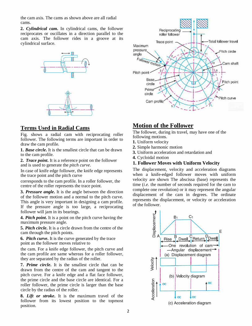
the cam axis. The cams as shown above are all radial cams. 2. Cylindrical cam. In cylindrical cams, the follower reciprocates or oscillates in a direction parallel to the cam axis. The follower rides in a groove at its cylindrical surface.
Terms Used in Radial Cams Fig. shows a radial cam with reciprocating roller follower. The following terms are important in order to draw the cam profile. 1. Base circle. It is the smallest circle that can be drawn to the cam profile. 2. Trace point. It is a reference point on the follower and is used to generate the pitch curve. In case of knife edge follower, the knife edge represents the trace point and the pitch curve corresponds to the cam profile. In a roller follower, the centre of the roller represents the trace point. 3. Pressure angle. It is the angle between the direction of the follower motion and a normal to the pitch curve. This angle is very important in designing a cam profile. If the pressure angle is too large, a reciprocating follower will jam in its bearings. 4. Pitch point. It is a point on the pitch curve having the maximum pressure angle. 5. Pitch circle. It is a circle drawn from the centre of the cam through the pitch points. 6. Pitch curve. It is the curve generated by the trace point as the follower moves relative to the cam. For a knife edge follower, the pitch curve and the cam profile are same whereas for a roller follower, they are separated by the radius of the roller. 7. Prime circle. It is the smallest circle that can be drawn from the centre of the cam and tangent to the pitch curve. For a knife edge and a flat face follower, the prime circle and the base circle are identical. For a roller follower, the prime circle is larger than the base circle by the radius of the roller. 8. Lift or stroke. It is the maximum travel of the follower from its lowest position to the topmost position.
Motion of the Follower
The follower, during its travel, may have one of the following motions. 1. Uniform velocity
2. Simple harmonic motion
3. Uniform acceleration and retardation and
4. Cycloidal motion 1. Follower Moves with Uniform Velocity
The displacement, velocity and acceleration diagrams when a knife-edged follower moves with uniform velocity are shown The abscissa (base) represents the time (i.e. the number of seconds required for the cam to complete one revolution) or it may represent the angular displacement of the cam in degrees. The ordinate represents the displacement, or velocity or acceleration of the follower.
2

Since the follower moves with uniform velocity
during its rise and return stroke, therefoore the slope of the displacement curves must be connstant. In other words, AB1 and C1D must be straight lines. A little consideration will show that the follower remains at rest during part of the cam rotation. The periods during
which the follower remains at rest are known as dwell
periods, as shown by lines B1C1 and DE . the
acceleration or retardation of the follower at the beginning and at the end of each stroke is infinite. This is due to the fact that the follower is required to start from rest and has to gain a velocity within no time. This is only possible if the acceleration or reetardation at the beginning and at the end of each stroke is infinite. These conditions are however, impracticable. In order to have the acceleration and retardation within the finite limits, it is necessary to modify the conditions which govern the motion of the followeer. This may be done by rounding off the sharp corners of the displacement diagram at the beginning and at the end of each stroke. By doing so, the velocity of the follower increases gradually to its maximum value at the beginning of each stroke and decreases gradually to zero at the end of each stroke.
S = Stroke of the follower
ΘO θR = Angular displacemennt of the cam during out stroke and return stroke of the follower respectively, in radians, and ω = Angular velocity of the ca m in rad/s. Consider a point P moving at a uniform speed ωP radians per sec round the circuumference of a circle with the stroke S as diameter. The point P′ (which is the projection of a point P on the diameter) executes a simple harmonic motion as the point P rotates. The motion of the follower is similaar to that of point P′.
Peripheral speed of the point P1
and maximum velocity of the follower on the outstroke, that the centripetal acceleration of the point P, Maximum acceleration of the folloower on the outstroke,
Similarly, maximum velocity of thhe follower on the return stroke,
and maximum acceleration of the follower on the return stroke,
2. Follower Moves with Simple Harmoonic Motion The displacement, velocity and acceleration diagrams when the follower moves with simple harmonic motion are shown .Since the follower moves with a simple harmonic motion, therefore velocity diaggram consists of a sine curve and the acceleration diagrram is a cosine curve. The velocity of the follower is zero at the beginning and at the end of its strokee and increases gradually to a maximum at mid-strokee. On the other hand, the acceleration of the follower is maximum at the beginning and at the ends of the stroke and diminishes to zero at mid-stroke.
3. Follower Moves with Uniform Acceleration and Retardation The displacement, velocity annd acceleration diagrams when the follower moves with uniform acceleration and retardation are shown. We know that time required for the follower during outstroke, tO = θO /ω and time required for the followwer during return stroke, tR = θR / ω Mean velocity of the follower during outstroke = S/tO
mean velocity of follower during return stroke = S/tR 3

Since the maximum velocity of followwer is equal to twice the mean velocity, therefore maximum velocity of the follower duringg outstroke,
Similarly, maximum velocity of the follower during return stroke,
During first half of the outstroke there is uniform acceleration and during the second half of the out stroke there is uniform retardation. Thus, the maximum
velocity of the follower is reached afterr the time tO / 2
(during out stroke) and tR /2 (during returrn stroke). Maximum acceleration of the follower during outstroke,
Similarly, maximum acceleration of the follower during return stroke,
4. Follower Moves with Cycloidal Motion
cycloid is a curve traced by a point on a circle when the circle rolls without slipping on a straight line. In case of cams, this straight line is a stroke of the follower which is translating and the circumferrence of the rolling circle is equal to the stroke (S) of the follower. Therefore the radius of the rolling circle is S / 2π
Let θ = Angle through which thhe cam rotates in time t seconds, and ω = Angular velocity of the cam. We know that displacement of the follower after time t seconds, ∴
Velocity of the follower after tiime t seconds,
.
The velocity is maximum, when
4

Substituting θ = θO / 2 we have maximum velocity of the follower during outstroke,
Similarly, maximum velocity of the follower during return stroke,
Now, acceleration of the follower after time t sec,
In order to draw the cam profile for a radial cam, first of all the displacement diagram for the given motion of the follower is drawn. Then by constructing the follower in its proper position at each angular position, the profile of the working surface of the cam is drawn. In constructing the cam profile, the principle of kinematic inversion is used, i.e. the cam is imagined to be stationary and the follower is allowed to rotate in the opposite direction to the cam rotation.
Case (i) Knife edge follower without offset : A cam is to give the following motion to a knife-edged follower : 1. Outstroke during 60° of cam rotation ;
2. Dwell for the next 30° of cam rotation ;
3. Return stroke during next 60° of cam rotation, and
4. Dwell for the remaining 210° of cam rotation. The stroke of the follower is 40 mm and the minimum radius of the cam is 50 mm. The follower moves with uniform velocity during both the outstroke and return strokes. Draw the profile of the cam when the axis of the follower passes through the axis of the cam shaft,
. Sol :
The acceleration is maximum, when
Substituting θ = θO / 4 we have maximum acceleration of the follower during outstroke,
Similarly, maximum acceleration of the follower during return stroke,
Construction of Cam Profile for a Radial Cam
5

Case (ii) Knife edge follower with offset : For the above problem in case (i) , if the follower is offset by 20 mm from the cam axis , then there is no change in the displacement diagram . But the construction of cam profile changes.
Case (iii) Roller follower with and without offset : An example problem is solved considering the roller follower with and without offset as two cases. Also it is asked to find the maximum acceleration and to draw the variation of displacement , velocity and acceleration A cam, with a minimum radius of 25 mm, rotating clockwise at a uniform speed is to be designed to give a roller follower, at the end of a valve rod, motion described below : 1. To raise the valve through 50 mm during 120° rotation of the cam ; 2. To keep the valve fully raised through next 30°; 3. To lower the valve during next 60°; and 4. To keep the valve closed during rest of the revolution i.e. 150° ; The diameter of the roller is 20 mm and the diameter of the cam shaft is 25 mm. Draw the profile of the cam when (a) the line of stroke of the valve rod passes through the axis of the cam shaft, and (b) the line of the stroke is offset 15 mm from the axis of the cam shaft. The displacement of the valve, while being raised and lowered, is to take place with simple harmonic motion. Determine the maximum acceleration of the valve rod when the cam shaft rotates at 100 r.p.m. Draw the displacement, the velocity and the acceleration diagrams for one complete revolution of the cam.
6

and maximum acceleration of the valve rod to lower the valve
Case (iv) Flat faced follower without offset
We know that angular velocity of the cam shaft,
We also know that maximum velocity of the valve rod to raise valve,
and maximum velocity of the valve rod to lower the valve, The velocity diagram for one complete revolution of the cam is shown We know that the maximum acceleration of the valve rod to raise the valve,
Case (v) Oscillating follower Draw a cam profile to drive an oscillating roller follower to the specifications given below : (a) Follower to move outwards through an angular displacement of 20° during the first 120° rotation of the cam ; (b) Follower to return to its initial position during next 120° rotation of the cam ; (c) Follower to dwell during the next 120° of cam rotation. The distance between pivot centre and roller centre = 120 mm ; distance between pivot centre and cam axis = 130 mm ; minimum radius of cam = 40 mm ; radius of roller = 10 mm ; inward and outward strokes take place with simple harmonic motion.
7

We know that the angular displacement of the roller follower = 20° = 20× π/180 = π / 9 rad Since the distance between the pivot centre and the roller centre (i.e. the radius A1 A) is 120 mm, therefore
length of the arc AA2, along which the displacement of the roller actually takes place = 120× π / 9 = 41.88 mm . . . (∵ Length of arc = Radius of arc × Angle subtended by the arc at the centre in radians)
Since the angle is very small, therefore length of chord AA2 is taken equal to the length of arc AA2. Thus in order to draw the displacement diagram, we shall take lift of the follower equal to
length of chord AA2 i.e. 41.88 mm.
8

UNIT V
Part-B
GEAR TRAINS
A gear train is two or more gear working together by meshing their teeth and turning
each other in a system to generate power and speed. It reduces speed and increases torque. To
create large gear ratio, gears are connected together to form gear trains. They often consist of
multiple gears in the train. Types of Gear trains :
1. Simple Gear Train In this gear train, there are series of gears which are capable of receiving and transmitting
motion from one gear to another. They may mesh externally or internally. Each gear
rotates about separate axis fixed to the frame. Figure shows two gears in external meshing.
Let t1, t2 be number of teeth on gears 1 and 2.
The two meshing gears in external meshing rotate in opposite sense whereas in internal
meshing they rotate in same sense. In simple gear train, there can be more than two gears also as
shown in Figure
1

Let N1, N2, N3, . . . be speed in rpm of gears 1, 2, 3, . . . etc., and t1, t2, t3, . . . be number of
teeth of respective gears 1, 2, 3, . . . , etc. In this gear train, gear 1 is input gear, gear 4 is output gear and gears 2, 3 are intermediate gears.
The gear ratio of the gear train is give by
This expression indicates that the intermediate gears have no effect on gear ratio. These
intermediate gears fill the space between input and output gears and have effect on the sense of
rotation of output gear
2. Compound Gear Train
In this type of gear train, at least two gears are mounted on the same shaft and they rotate
at the same speed. This gear train is shown in Figure 3.30 where gears 2 and 3 are
mounted on same shaft and they rotate at the same speed, i.e. N2 , N3
Let N1, N2, N3, . . . be speed in rpm of gears 1, 2, 3, . . . , etc. and t1, t2, t3, . . . , etc. be number
of teeth of respective gears 1, 2, 3, . . . , etc.
2

Therefore, unlike simple gear train the gear ratio is contributed by all the gears. This gear train is
used in conventional automobile gear box.
3. Reverted Gear Train:
When the axes of the first gear (i.e. first driver) and the last gear (i.e. last driven or follower) are
co-axial, then the gear train is known as reverted gear train as shown in Fig. We see that gear 1
(i.e. first driver) drives the gear 2 (i.e. first driven or follower) in the opposite direction. Since the
gears 2 and 3 are mounted on the same shaft, therefore they form a compound gear and the gear
3 will rotate in the same direction as that of gear 2. The gear 3 (which is now the second driver)
drives the gear 4 (i.e. the last driven or follower) in the same direction as that of gear 1. Thus we
see that in a reverted gear train, the motion of the first gear and the last gear is like
Since the distance between the centres of the shafts of gears 1 and 2 as well as gears 3 and
4 is same
Also, the circular pitch or module of all the gears is assumed to be same, therefore number
of teeth on each gear is directly proportional to its circumference or radius
3
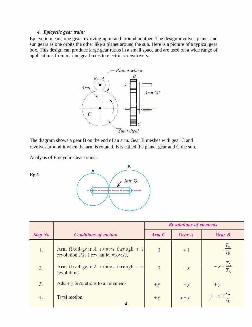
4. Epicyclic gear train: Epicyclic means one gear revolving upon and around another. The design involves planet and
sun gears as one orbits the other like a planet around the sun. Here is a picture of a typical gear
box. This design can produce large gear ratios in a small space and are used on a wide range of
applications from marine gearboxes to electric screwdrivers.
The diagram shows a gear B on the end of an arm. Gear B meshes with gear C and
revolves around it when the arm is rotated. B is called the planet gear and C the sun.
Analysis of Epicyclic Gear trains :
Eg.1
4

Eg.2
5

Eg.3
6

Eg.4
7

Eg.5
8

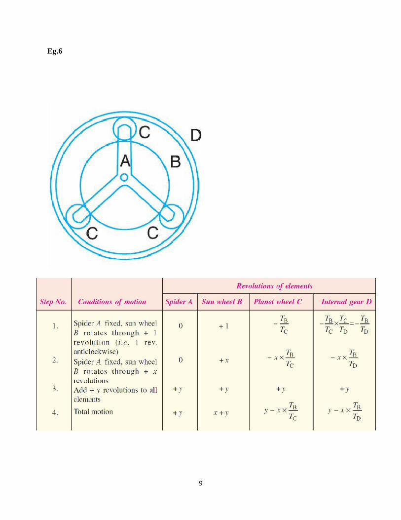
Eg.6
9

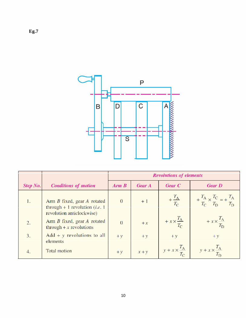
Eg.7
10

Eg.8
Differential of Automobile : The differential gear used in the rear drive of an automobile is shown in Fig. . Its function is
(a) to transmit motion from the engine shaft to the rear driving wheels, and (b) to rotate the rear
wheels at different speeds while the automobile is taking a turn. As long as the automobile is
running on a straight path, the rear wheels are driven directly by the engine and speed of both the
wheels is same. But when the automobile is taking a turn, the outer wheel will run faster than the
inner wheel because at that time the outer rear wheel has to cover more distance than the inner
rear wheel. This is achieved by epicyclic gear train with bevel gears as shown in Fig. The bevel
gear A (known as pinion) is keyed to the propeller shaft driven from the engine shaft through
11

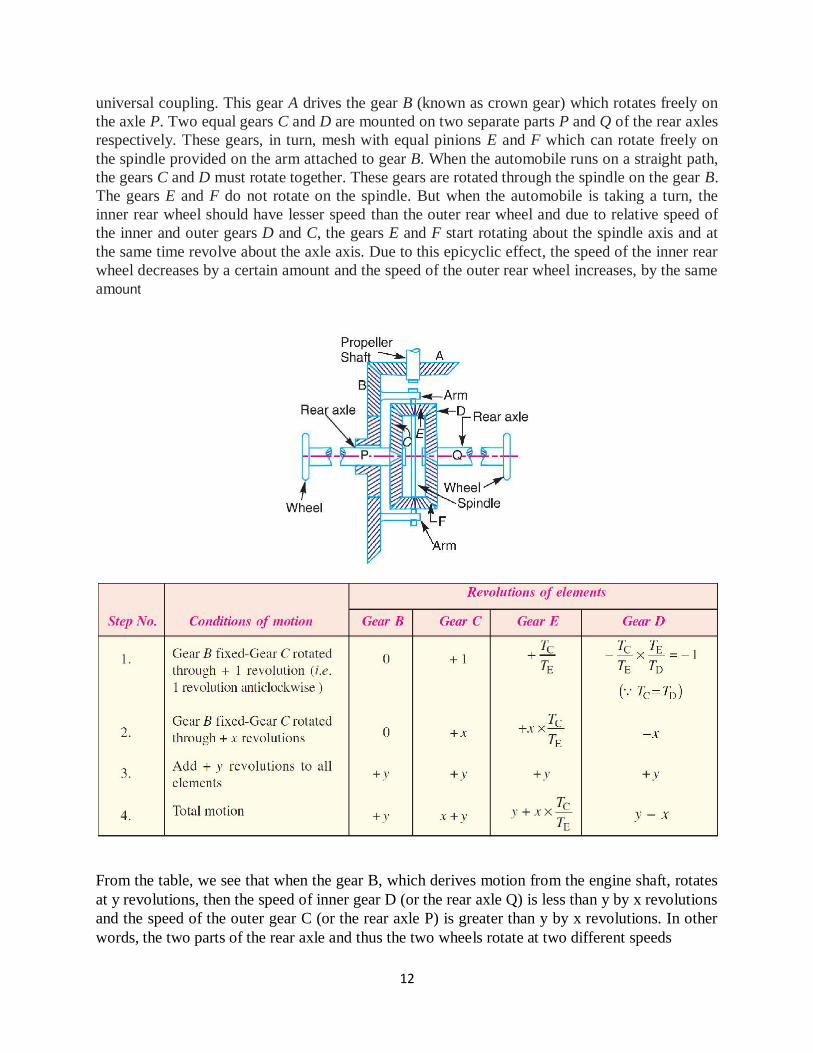
universal coupling. This gear A drives the gear B (known as crown gear) which rotates freely on
the axle P. Two equal gears C and D are mounted on two separate parts P and Q of the rear axles
respectively. These gears, in turn, mesh with equal pinions E and F which can rotate freely on
the spindle provided on the arm attached to gear B. When the automobile runs on a straight path,
the gears C and D must rotate together. These gears are rotated through the spindle on the gear B.
The gears E and F do not rotate on the spindle. But when the automobile is taking a turn, the
inner rear wheel should have lesser speed than the outer rear wheel and due to relative speed of
the inner and outer gears D and C, the gears E and F start rotating about the spindle axis and at
the same time revolve about the axle axis. Due to this epicyclic effect, the speed of the inner rear
wheel decreases by a certain amount and the speed of the outer rear wheel increases, by the same
amount
From the table, we see that when the gear B, which derives motion from the engine shaft, rotates
at y revolutions, then the speed of inner gear D (or the rear axle Q) is less than y by x revolutions
and the speed of the outer gear C (or the rear axle P) is greater than y by x revolutions. In other
words, the two parts of the rear axle and thus the two wheels rotate at two different speeds
12

UNIT V
Part-B
GEAR TRAINS
A gear train is two or more gear working together by meshing their teeth and turning
each other in a system to generate power and speed. It reduces speed and increases torque. To
create large gear ratio, gears are connected together to form gear trains. They often consist of
multiple gears in the train. Types of Gear trains :
1. Simple Gear Train In this gear train, there are series of gears which are capable of receiving and transmitting
motion from one gear to another. They may mesh externally or internally. Each gear
rotates about separate axis fixed to the frame. Figure shows two gears in external meshing.
Let t1, t2 be number of teeth on gears 1 and 2.
The two meshing gears in external meshing rotate in opposite sense whereas in internal
meshing they rotate in same sense. In simple gear train, there can be more than two gears also as
shown in Figure
1

Let N1, N2, N3, . . . be speed in rpm of gears 1, 2, 3, . . . etc., and t1, t2, t3, . . . be number of
teeth of respective gears 1, 2, 3, . . . , etc. In this gear train, gear 1 is input gear, gear 4 is output gear and gears 2, 3 are intermediate gears.
The gear ratio of the gear train is give by
This expression indicates that the intermediate gears have no effect on gear ratio. These
intermediate gears fill the space between input and output gears and have effect on the sense of
rotation of output gear
2. Compound Gear Train
In this type of gear train, at least two gears are mounted on the same shaft and they rotate
at the same speed. This gear train is shown in Figure 3.30 where gears 2 and 3 are
mounted on same shaft and they rotate at the same speed, i.e. N2 , N3
Let N1, N2, N3, . . . be speed in rpm of gears 1, 2, 3, . . . , etc. and t1, t2, t3, . . . , etc. be number
of teeth of respective gears 1, 2, 3, . . . , etc.
2

Therefore, unlike simple gear train the gear ratio is contributed by all the gears. This gear train is
used in conventional automobile gear box.
3. Reverted Gear Train:
When the axes of the first gear (i.e. first driver) and the last gear (i.e. last driven or follower) are
co-axial, then the gear train is known as reverted gear train as shown in Fig. We see that gear 1
(i.e. first driver) drives the gear 2 (i.e. first driven or follower) in the opposite direction. Since the
gears 2 and 3 are mounted on the same shaft, therefore they form a compound gear and the gear
3 will rotate in the same direction as that of gear 2. The gear 3 (which is now the second driver)
drives the gear 4 (i.e. the last driven or follower) in the same direction as that of gear 1. Thus we
see that in a reverted gear train, the motion of the first gear and the last gear is like
Since the distance between the centres of the shafts of gears 1 and 2 as well as gears 3 and
4 is same
Also, the circular pitch or module of all the gears is assumed to be same, therefore number
of teeth on each gear is directly proportional to its circumference or radius
3

4. Epicyclic gear train: Epicyclic means one gear revolving upon and around another. The design involves planet and
sun gears as one orbits the other like a planet around the sun. Here is a picture of a typical gear
box. This design can produce large gear ratios in a small space and are used on a wide range of
applications from marine gearboxes to electric screwdrivers.
The diagram shows a gear B on the end of an arm. Gear B meshes with gear C and
revolves around it when the arm is rotated. B is called the planet gear and C the sun.
Analysis of Epicyclic Gear trains :
Eg.1
4

Eg.2
5

Eg.3
6

Eg.4
7

Eg.5
8
Eg.6
9
Eg.7
10

Eg.8
Differential of Automobile : The differential gear used in the rear drive of an automobile is shown in Fig. . Its function is
(a) to transmit motion from the engine shaft to the rear driving wheels, and (b) to rotate the rear
wheels at different speeds while the automobile is taking a turn. As long as the automobile is
running on a straight path, the rear wheels are driven directly by the engine and speed of both the
wheels is same. But when the automobile is taking a turn, the outer wheel will run faster than the
inner wheel because at that time the outer rear wheel has to cover more distance than the inner
rear wheel. This is achieved by epicyclic gear train with bevel gears as shown in Fig. The bevel
gear A (known as pinion) is keyed to the propeller shaft driven from the engine shaft through
11
universal coupling. This gear A drives the gear B (known as crown gear) which rotates freely on
the axle P. Two equal gears C and D are mounted on two separate parts P and Q of the rear axles
respectively. These gears, in turn, mesh with equal pinions E and F which can rotate freely on
the spindle provided on the arm attached to gear B. When the automobile runs on a straight path,
the gears C and D must rotate together. These gears are rotated through the spindle on the gear B.
The gears E and F do not rotate on the spindle. But when the automobile is taking a turn, the
inner rear wheel should have lesser speed than the outer rear wheel and due to relative speed of
the inner and outer gears D and C, the gears E and F start rotating about the spindle axis and at
the same time revolve about the axle axis. Due to this epicyclic effect, the speed of the inner rear
wheel decreases by a certain amount and the speed of the outer rear wheel increases, by the same
amount
From the table, we see that when the gear B, which derives motion from the engine shaft, rotates
at y revolutions, then the speed of inner gear D (or the rear axle Q) is less than y by x revolutions
and the speed of the outer gear C (or the rear axle P) is greater than y by x revolutions. In other
words, the two parts of the rear axle and thus the two wheels rotate at two different speeds
12