2.017 design of electromechanical robotic systems lab 4.pdf · • duty cycle = pulsewidth / pwm...
TRANSCRIPT

2.017 DESIGN OF ELECTROMECHANICAL ROBOTIC SYSTEMS
Fall 2009 Lab 4: Motor ControlOctober 5, 2009
Dr. Harrison H. Chin

Formal Labs
1. Microcontrollers• Introduction to microcontrollers• Arduino microcontroller kit
2. Sensors and Signals• Analog / Digital sensors• Data acquisition• Data processing and visualization
3. GPS and Data Logging• GPS receiver and shield • Data logging• Visualization of data
4. Motor Control• Motors• Encoders• Position control

Fall 2009 Calendar
9/9: First day of classes
10/12: Columbus Day—Holiday10/13: Monday schedule
W1
W2
W3
W4
W5
W6
W7
W8
Lab 1: Lab Intro, Arduino microcontroller
Lab 3: GPS & data logging
Lab 4: Motor control
Term project proposal (W4)
Formal labs: 4 weeksTerm project: 8 weeks
Lab 2: Sensors & signals, A/D, D/A, PWM
Term project starts (W6)

Fall 2009 Calendar (Cont.)
11/11: Veteran’s Day—Holiday
11/26-27: Thanksgiving Vacation
12/10: Last day of classes
W9
W10
W11
W12
W13
W14
Term project presentation (12/8 & 12/10)
Term project milestone presentation (11/5)
Term project draft (12/1)

Lab 4: Motor Control
• DC motor experiments (1:30 – 3:30)– Processing Encoder Signals – Implementing Closed-Loop Position Control– Higher Performance from the Control System– Velocity Control
• Controlling a Servo (3:30 – 4:30)
• Project discussion (4:30 – 5:00)

Hardware Setup
Arduino
Motor Shield
PC6-C-4 Decoder Circuit
Maxon DC Motor
External Power
USB

DC Motors
Permanent Magnets
Armature
Terminal
Brush
Commutator
Winding
1)()(
2
1
+⎟⎠⎞
⎜⎝⎛ ⋅
=Ω −
sKJRK
sVs
t
mm
t
Time constantWhat is the time constant for our Maxon F2140.937 motor?

Optical Encoders
Regular phase
Quadrature phase

Quadrature Decoding
X (Ch A) Y (Ch B) F0 F1 F2 F3
0 0 1 0 0 0
1 0 0 1 0 0
1 1 0 0 1 0
0 1 0 0 0 1

Decoder Circuit
• The PC6 decoder by US Digital decodes the quadrature outputs of an incremental shaft encoder. The circuit we use is the PC6-C-4, clock and direction version that provides 4x the encoder resolution.
• For the Maxon motor each encoder channel has 100 counts and through a 6:1 ratio gearhead we get 600 counts per channel (see Maxon motor specs).
• With the PC6-C-4 decoder circuit we get a total of 4x600 = 2,400 counts per shaft rotation.

Encoder Signals and Decoder Circuit Timing Diagram
• Check the following signals with an Oscilloscope

Arduino Motor Shield
• 2 connections for 5V 'hobby' servos• Up to 4 bi-directional DC motors • Up to 2 stepper motors (unipolar or bipolar) with
single coil, double coil, interleaved or micro-stepping.
• 4 H-Bridges: L293D chipset provides 0.6A per bridge (1.2A peak) with thermal shutdown protection, 4.5V to 36V
• Pull down resistors keep motors disabled during power-up
• Arduino reset button brought up top • 2-pin terminal block to connect external power,
for separate logic/motor supplies

L293D Quadruple Half-H Driver (H-Bridge)
• The L293D is a quadruple high-current half-H driver.
• The L293D is designed to provide bidirectional drive currents of up to 600-mA at voltages from 4.5 V to 36 V.
• It is designed to drive inductive loads such as relays, solenoids, dc and bipolar stepping motors, as well as other high-current/high-voltage loads in positive-supply applications.
An H-bridge enables a voltage to be applied across a load in either direction.

Pulse Width Modulation (PWM)
• PWM frequency (Hz) = 1 / PWM period• Duty cycle = Pulsewidth / PWM period• PWM frequencies typically range from 100Hz into MHz• Duty cycles can be used from 0 – 100%, although some systems
use much smaller ranges, e.g. 5-10% for hobby remote servos.• The waveform has two pieces of information: Period and
Pulsewidth, although they are usually not changed simultaneously.
Use a scope to look at the PWM signal if you can
Volts Vpeak
Time
PWM period Pulsewidth

Pulse Width Modulation (PWM)
• Can be used as a substitute for analog output (high frequency switching is filtered out by the physical systems and what is left is the mean voltage).
• Applications include: lamp dimmers, motor speed control, power supplies,…
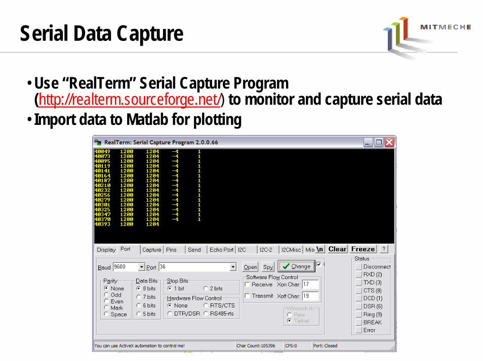
Serial Data Capture
• Use “RealTerm” Serial Capture Program (http://realterm.sourceforge.net/) to monitor and capture serial data
• Import data to Matlab for plotting

Controller Design
• Control action Types:– Proportional – improve speed but with steady-state error– Integral – improve steady state error but with less stability, overshoot, longer
transient, integrator windup– Derivative – improve stability but sensitive to noise
• Reduce overall gain can increase stability but with slower response
• Avoid saturation• Set integrator limit to prevent windup

Matlab SISOTOOL Controller Design Tool

Simulink Simulation
sKs
KK di
p ++
PP II DD
Position transfer function
sKsKsK
sKs
KKsG ipdd
ipc
++=++=
2
)(

Motor Control Template Code
void setup() Serial.begin(9600); // set up Serial library at 9600 bps Kp = 0.0; Ki = 0.0; Kd = 0.0; pinMode(ClockPin, INPUT); pinMode(UpDownPin, INPUT);
// encoder pin on interrupt 0 (pin 2) attachInterrupt(0, doEncoder, CHANGE); time_1 = millis(); // read the initial time stamp
void loop() // Serial.println("Motor Control"); time_2 = millis(); // read the current time stamp dt = time_2 - time_1; // compute delta time time_1 = time_2; // reassign new time_1 //*** Remeber time is in milliseconds!!! // update state variables for use in PID controller vel = (float) (encoder0Pos - oldPos) / dt; // velocity estimate in ms error = setPoint - encoder0Pos; // position error in counts // reassign state variables oldPos = encoder0Pos; //*********************************** // Insert controller here // command = ???? // // remember command should be an integer //***********************************
Fill in your PID gains
Fill in your controller equations

Step Response Comparison
05.00.1
25.0
==
=
d
i
p
KK
K

Servomotor Control
• Can be positioned from 0 to 180 degrees
• An internal DC motor connected to a potentiometer
• High torque gearing
• Internal feedback circuitry to control motor position
• Three wire connector: Ground, +5 V, and PWM (typically at 50 Hz)
Modify the code to use a potentiometer (or a photo resistor) to control the shaft angle

Stepper Motor
• Permanent magnet in rotor• Windings on stator poles • Excitation of phase windings produces discrete steps• 2 phase, 1.8°/step most common
Hybrid Stepper Motor

Project Discussion
• Project proposal feedback

Deliverables
• Answer all the questions in the Lab 4 handout
• Plots
• Show the teaching staff your lab notebook