2017 utah air agencies oil & gas emissions inventory workbook instructions · 2017 utah air...
TRANSCRIPT
1
2017 Utah Air Agencies Oil & Gas Emissions Inventory Workbook
Instructions
2
Table of Contents Introduction ..................................................................................................................................... 3
Saving and Submitting the Workbook ............................................................................................. 4
Entering Data in Workbook ............................................................................................................. 5
Included Worksheets ....................................................................................................................... 6
Website Upload Instructions....................................................................................................... 6
Operator Information ................................................................................................................. 6
Facilities List ................................................................................................................................ 6
Associated API #s ........................................................................................................................ 7
ProdAreaDesignation&Analyses ................................................................................................. 8
Production Area Designations and Analyses Summary ........................................................... 8
Production Area Analyses – How to Report Analyses ............................................................. 8
Component Counts by Area Designation ................................................................................ 9
Drill_Compl._Recompl._Workover ............................................................................................. 9
RICE / Turbines .......................................................................................................................... 10
Separators / Line Heaters / Heater-Treaters / Tank Heaters / Reboilers ................................. 12
Dehydrators .............................................................................................................................. 13
Tanks ......................................................................................................................................... 15
Truck Loading ............................................................................................................................ 19
Pneumatic Controllers .............................................................................................................. 20
Pneumatic Pumps ..................................................................................................................... 20
Fugitives .................................................................................................................................... 21
Produced Water and Injection .................................................................................................. 22
Centrifuges ................................................................................................................................ 23
Solid Waste Disposal ................................................................................................................. 24
Company Summary ................................................................................................................... 24
Appendix ........................................................................................................................................ 25
Figure 1. Produced Water and Injection Flowchart .................................................................. 25
3
Introduction This Microsoft Excel workbook is designed to help the user estimate emissions at oil & gas
facilities with Standard Industrial Classification codes in the major group 13 that have uncontrolled
actual emissions greater than one ton per year for any single pollutant including: PM10, PM2.5, NOx,
SOx, CO, or VOC. These sources include, but are not limited to, industries involved in oil and
natural gas exploration, production, and transmission (boosting stations (i.e. transmission
compression stations) and line heaters) operations; well production facilities; natural gas
compressor stations; and natural gas processing plants and commercial oil and gas disposal wells,
ponds and sites. The period being estimated for is calendar year 2017 (Jan. 1 – Dec. 31, 2017).
The step-by-step instructions below will aid the user in filling out this customized workbook. It
will help to have a copy of the workbook open while reading these instructions to increase
understanding.
To begin, open the Excel file named “2017_Utah_O&G_EI_Workbook.” Tabs identifying
worksheets that are linked and interactive will be displayed across the bottom of the workbook.
All but two of these worksheets are modifiable and require inputs from the user for the
workbook to correctly calculate the emissions inventory. When inserting new data (in some
cases by typing over the top of existing data), the new data will automatically be distributed to
the proper cells and worksheets; thereby, reducing inventory time and the chance for errors.
Fields shaded in grey should not be modified by the user unless the instructions for that field
explicitly state to do so. Fields that are shaded in pink are optional, and are not required to be
provided by the user. Worksheets in this workbook include “Operator Info”, “Facilities List”,
“Associated API #s”, “ProdAreaDesignation&Analyses”, “Drill_Compl._Recompl._Workover”,
“RICE&Turbines”, “Separators&Heaters”, “Dehydrators”, “Tanks”, “Truck Loading”, “Pneumatic
Controllers”, “Pneumatic Pumps”, “Fugitives”, “Produced Water and Injection”, “Centrifuges”,
and “Solid Waste Disposal”. The workbook also contains “Website Upload Instructions” and
“Company Summary” worksheets that do not need to be modified.
For any questions or concerns about completing the O&G Emissions Inventory Workbook
please contact UDAQ: Greg Mortensen (801) 536-4018, [email protected] or Whitney
Oswald (801) 536-4468, [email protected].

4
Saving and Submitting the Workbook Please rename and save the workbook as “2017_Utah_O&G_ EI_Workbook_Company Name”
replacing company name with your own company’s name. Example:
“2017_Utah_O&G_EI_Workbook_AcmeIndustries”. Remember to periodically save the
workbook while entering new data.
In addition to the workbook, various supporting documents must be submitted as well, this
includes:
Manufacturer specification sheet or copy of stack test results for Rice/Turbines if not using default emission factors
Manufacturer specification sheet for combustors
Representative GLYCalc or ProMax report(s) for dehydrators
Produced Natural Gas Analysis, Flash Gas Analysis, and Standing/Working/Breathing Gas Analysis for each production area noted (other than “Default”) on the “ProdAreaDesignation&Analyses” tab
Pressurized liquid sample analyses used as input to tank emission estimating models.
Once the data input has been completed, the workbook can be uploaded and sent to Utah Division of Air Quality (UDAQ) using the following method.
Users must request an account by going to http://ogei.autosciencetech.org and clicking “Request Account” at the top right corner of the page. This will bring you to a page where you can create the credentials for your account. Username must be a minimum of 3 characters long and consist of alphanumeric characters (a-z,
A-Z, 0-9) or underscores “_” only. Your password must be a minimum of 8 characters long,
containing at least one capital character, one lowercase character and one number. The email
address will be used only for password resets in the event that your password is lost or expires
(state policy dictates passwords must expire every 90 days). NOTE: Password reset has not
been implemented at this time – Be certain not to lose your password, or you will need to
create a new account until this is resolved!
After establishing an account, access must be granted by a Utah Divisiog of Air Quality (DAQ)
employee to use the system. If there is a delay in granting access, contact Greg Mortensen at
801-536-4018 or [email protected]. If you attempt to log in with your credentials access is
granted, you will receive an “Account Disabled” error message.
5
Once account access is granted, users may log in and will be able to use the “File Uploader”.
Clicking on the “Upload File” button will open up a file dialogue box where users can select the
file(s) to upload. After clicking Open, the upload will begin and the progress bar should begin
filling.
To check if the file was uploaded successfully, users can click “Upload History” to view the files
uploaded to the system and the newest documents will be at the top of the list.
The file will appear as “Quarantined” shortly after upload, while it awaits a virus scan. While in
quarantine, it cannot be accessed by the application. This should lift shortly after upload. If a
file has remained in a quarantined state for an extended period of time, contact Greg
Mortensen at 801-536-4018 or [email protected]. Only files uploaded by the user are
available on this page, and users may download files that are out of quarantine if unsure what
data was included in a specific upload.
Assistance: If you have any questions or problems while using this system, please contact Greg Mortensen (801) 536-4018, [email protected] or Whitney Oswald (801) 536-4468, [email protected]
Entering Data in Workbook Most fields are modifiable and can be filled in by the operator; however any fields that are static
parameters and should not be adjusted are shaded grey. The workbook also includes several
drop-down lists which must be selected by the user, and once selected will appear in a blue
font. When entering data into the worksheets, be sure to enter the values in exactly the same
units that are listed. Units are not modifiable since the calculations in the workbook depend on
continuity of units. The current units are standard for calculating emissions at oil & gas
operations.
Each worksheet is defaulted with 2000 rows to report equipment or activity. Note: If your
company has more than 2000 pieces of any one equipment type or activity, or more than 2000
facilities, contact UDAQ for further instruction.
Note: Please do NOT include Title V point source permitted facilities in your submission. This
workbook is limited to area source emissions. Title V point source emissions are accounted for
by separate point source workbooks provided to those sources by UDAQ.
6
Included Worksheets
Website Upload Instructions This tab provides all the necessary instruction regarding how to upload your final workbook and
supporting documentation to UDAQ once your workbook is complete. This process is also
described in the “Saving and Submitting the Workbook” section above.
Operator Information This tab is for providing basic operator information such as name and address as well as at least
one person of contact, and their relevant information, for the operator.
1. Operator Name – Provide the name of the operator (abbreviate name). Note: an abbreviated name is recommended as a lengthy name will surpass “Facility Unique ID #” field width limits. The field is used in subsequent worksheets and an inability to view the full ID will result in difficulty selecting a specific facility.
2. Operator Address – Provide the address for the operator, including: Street Address, City, State, and Zip code.
3. Contact Name – Provide the name of the main contact for the operator.
4. Contact Title – Provide the contact title for the operator’s main contact.
5. Daytime Phone Number – Provide the phone number for the operator’s main contact.
6. Email – Provide the email address for the operator’s main contact.
7. Alternate Contact Name – Optionally provide an alternate contact for the operator.
8. Alternate Contact Title – Optionally provide the contact title for the operator’s alternate contact.
9. Alternate Phone Number – Optionally provide the phone number for the operator’s alternate contact.
10. Alternate Email -- Optionally provide the email address for the operator’s alternate contact.
Facilities List This tab is for providing a list of all active upstream, midstream and transmission (boosting
stations (i.e. transmission compression stations) and line heaters) sources owned/operated by
the operator completing the workbook. Facilities with a Title V Operating permit in effect, do
not need to be listed. Each line in this tab represents a separate facility.
7
1. Facility Name – Provide the full name of the facility.
2. Facility Unique ID # – This field does not need to be completed by the operator. This field is generated by the workbook. Note: This field should be used as the main identifier for each facility for the remainder of the workbook.
3. Facility Type and Annual Throughputs – Using the dropdown menu, select the appropriate facility description. Note: If the production facility is a coal bed methane well, please note that in the comments section. If “Other”, please include a description in the comments section. Add production of oil/condensate/gas/water or throughput of produced water/solid waste as applicable:
Production Facility – enter the annual production totals in the appropriate field in the specified units.
Midstream Facility – including compressor stations, centralized tank batteries, etc. No throughput reporting is necessary.
Produced Water Disposal Facility – enter the annual produced water received in the specified units.
Water Injection Facility – enter the annual produced water received in the specified units.
Solid Waste Facilities – enter the annual solid waste received in the specified units.
Other – e.g. boosting stations (i.e. transmission compression stations) and line heaters
4. Facility Permit ID (Approval Order, Tribal Minor Source Registration) – Provide the permit ID for any air permit the facility is permitted under.
5. Latitude – Provide the latitude of the facility in decimal degrees (e.g. DD.ddddd).
6. Longitude – Provide the longitude of the facility in decimal degrees (e.g. DD.ddddd).
7. Production Area Designation – The user should select appropriate production area designation for each facility using the drop down menu. Note: Select “Default” UNLESS you will be providing composition analyses for the given production area designations in the “ProductionAreaDesignation&Analyses” tab.
8. Comments – Provide any additional comments relating to the facility, if needed.
Associated API #s This tab is for providing a list of any API #s associated with each facility listed in the facilities tab.
1. Facility Unique ID # – Provide the Facility Unique ID # that was assigned to the facility in the Facilities tab.
8
2. Associated API #X – Provide each individual API number associated with the noted facility. Note: If any facility is associated with more than 100 API numbers, contact UDAQ for further instruction.
ProdAreaDesignation&Analyses This tab should be used to report a production gas analysis, flash gas analysis, and
standing/working/breathing gas analysis for each reported facility. Additionally the tab should
be used to report component counts for each area designation.
Production Area Designations and Analyses Summary
This table is a summary table which auto-populates based on the information provided by the
user in the “Production Area Analyses” tables and the “Component Counts by Area Designation”
tables. This table is also used by other tabs within the workbook. This table should not be
modified by the user.
Production Area Analyses – How to Report Analyses
Each facility reported on the “Facilities List” tab must have an associated set of analyses. For
each facility, users may either provide a unique set of analyses, provide a representative set of
analyses (may be utilized for more than one facility), or use the default set of analyses already
provided in the workbook. Regardless of the method used, the set of analyses used for each
individual facility should be noted in the “Facilities List” tab by noting the “Production Area
Designation” name assigned to the specific set of analyses (e.g. “Default” or “1”, “2”,”3”, etc.)
using the dropdown for the “Production Area Designation” field.
Space is provided for submission of up to 10 different sets of analyses (identified by the
production area designations of “1-10”). If a user needs to submit more than 10 sets of analyses
they should contact UDAQ for further instruction.
Note: If unique or representative analyses are provided, supporting documents must be
submitted as well.
Each set of analyses should include: “Produced Natural Gas Composition”, “Flash Gas Analysis”,
and “Standing Working Breathing Gas Analysis”. For each analysis the user should provide the
following information:
1. Gas MW –The gas molecular weight of the gas collected for sample in pound per pound mole (lb/lb-mole). This field requires no manual input, the field will be auto calculated from the data provided in the Mole Fraction fields. The populated data should not be modified by the user.
2. VOC Wt. % – The volatile organic compound (VOC) weight percent of the gas collected for sample. This field requires no manual input, the field will be auto calculated from the data provided in the Mole Fraction fields. The populated data should not be modified by the user.

9
3. Heat Content (BTU/scf) – Provide the heat content of the gas collected for sample in British thermal units per standard cubic feet (BTU/scf).
4. GOR – Provide the gas oil ratio for the analysis.
5. # of Samples Taken – Provide the number of samples used to develop the noted representative sample.
6. Mole Fraction – Provide the mole fraction obtained from the production gas analysis completed for the sample of interest including: CO2, N2, C1, C2, C3, C4, C5, C6, C7, C8, C9, C10, Benzene, Toluene, Ethylbenzene, Xylene, and N-Hexane.
Component Counts by Area Designation
These tables should be used to provide the average component counts for each unique
production area designation utilized by the user. Default counts have already been provided for
the “Default” production area designation. The user should complete the component counts
table for any production area designation they provided analyses for in the “Production Area
Analyses” tables.
These tables use the provided component counts along with EPA based fugitive equipment leak
emission factors to determine “Emissions lb/hr” and “Total Emissions lb/hr” (these fields should
not be modified by the user).
Drill_Compl._Recompl._Workover This tab is for estimating emissions at the well site during the drilling, completion, recompletion,
and workover processes. Emission factors assume the following: 7.5 lb of diesel per gallon,
diesel heating value of 19,300 btu/lb (AP 42 3.3-1), and average brake-specific fuel consumption
of 7,000 btu/hp-hr.
Note: Drill Rig/Well Completion/Recompletion/Workover engines should be reported here
rather than the RICE&Turbines tab.
1. Facility Unique ID # – Provide the Facility Unique ID # that was assigned to the facility in the Facilities tab using the dropdown menu or by manually entering the ID (manual entry of the ID will require user confirmation of entry).
2. Affected API # – Provide the API number of the specific well that is being drilled, completed, recompleted or serviced/workover.
3. Well Type – Using the dropdown menu, select the well type for the well that is being completed.
4. Activity Type – Using the dropdown menu, select the activity type for the operation.
10
5. Total Gas and Liquids Flared or Vented During Drilling, Completion Provide the annual product flared or vented under the appropriate subcategory in the appropriate units (mmcf or bbl) specified by subcategory.
6. Annual Diesel Fuel Usage – Provide the annual diesel fuel usage for the well that was drilled or completed in gallons.
7. Drill Rig/Completion Engine/Workover Engine Control - Control Type – This field contains a drop-down list of control types that can be selected by the user.
8. Drill Rig/Completion Engine/Workover Engine Control - NOx (%) – This field is prepopulated to 0% control. If the user selected a control in the previous field the percent NOx control should be noted in this field.
9. Gas Flaring Control - Flare Efficiency – This field contains a drop-down list of flare efficiencies that can be selected by the user.
10. Gas Flaring Control - Percent Control (%) – This field notes the percent control used for controlling gas flaring. This field is auto-populated based on the selection made in the previous field. This field should not be modified by the user.
11. Release Point – Provide the relevant release point data in the appropriate units specified for each subcategory.
12. Emission Factors – These fields contain emission used to calculate the emissions from drilling, well completions, and workovers. These fields should not be modified by the user.
13. Emissions – These fields contain the formulas that calculate the PM10, PM2.5, NOx, VOC, and CO (tons/yr) emissions associated with each well completion and should not be modified by the user.
RICE (Reciprocating Internal Combustion Engines) & Turbines Natural Gas and Diesel using AP 42 Emission Factors
This tab is for estimating emissions from reciprocating engines and turbines using emission
factors from AP 42 3.1, 3.2, 3.3, and 3.4, NSPS JJJJ, manufacturer specifications, or stack tests.
1. Facility Unique ID # – Provide the Facility Unique ID # that was assigned to the facility in the Facilities tab using the dropdown menu or by manually entering the ID (manual entry of the ID will require user confirmation of entry).
2. Make – Provide the make of the RICE/Turbine for which you are reporting.
3. Model – Provide the model of the RICE/Turbine for which you are reporting.
4. Manufacturer Year – Provide the manufacturer year (yyyy) of the RICE/Turbine you are reporting.

11
5. Engine Type – This field contains a drop-down menu of RICE/Turbine function types; select the one that best fits the RICE/Turbine for which you are reporting.
6. Site Rated Horsepower – Provide the site rated horsepower (hp) of the RICE/Turbine you are reporting.
7. Total Annual Hours of Operation – Provide the annual operating hours (hrs) of the RICE/Turbine you are reporting.
8. Engine Category – This field contains a drop-down list of engine and turbine category types that can be selected.
9. Total Fuel Combusted – Provide the total amount of fuel combusted for the category type can be entered. It is important to note that this number must be entered in the same units that are displayed in the “Units” field.
10. Units – This field automatically populates according to the category type selected from the drop-down listed in the Engines / Compressors / Turbines field. This field should not be modified by the user.
11. Fuel Heating Value – Provide the heating value of the fuel used for the category type entered. It is important to note that this number must be entered in the same units that are displayed in the “Heating Value Units” field.
12. Heating Value Units - This field automatically populates according to the category type selected from the drop-down listed in the Turbines/Compressors/Engines field. This field should not be modified by the user.
13. Heat Throughput – This is a field that calculates the total heat throughput of the fuel in mmbtu/yr (million British thermal units per year) by using the entries from “Total Fuel” and “Fuel Heating”. This field should not be modified by the user.
14. Control Type – This field contains a drop-down list of two selections, Controlled, and Uncontrolled. Select the control status that best fits the RICE/Turbine you are reporting.
15. NOx (%) – This field is formatted as a percentage and should be used to report the percent control for NOX. An example would be a category that only has a NOX control of 50%. The user would enter 50 in the NOX (%).
16. Release Point – These are modifiable fields where users can use the pre-entered defaults or can provide specific information about the release point (stack or fugitive) related to each piece of reported equipment or activity. If no stack exists please change the selection in the Stack/Fugitive column to “Fugitive”.
17. Emission Factors: EF Type – This field contains a drop-down list with four emissions factor type choices: AP_42, NSPS_JJJJ, Manufacturer_Spec., and Stack_Test (some EF Types only available for certain pollutants). For each emissions category (PM10, PM2.5, SOx, NOx, VOC, CO, CH2O) select the type that best fits the RICE/Turbine you are reporting.
12
18. Emission Factors: Category – This field contains a drop-down list with several choices, the choices will be narrowed depending on the selection made in the prior field “EF Type”. For each emissions category (PM10, PM2.5, SOx, NOx, VOC, CO, CH2O) select the category that best fits the RICE/Turbine you are reporting.
19. Emission Factors: Factor and Units - The values in these fields will automatically populate with emission factors if the type selected in the “EF Type” field was AP 42 or NSPS JJJJ. Otherwise the field should be completed by the operator by providing an emission factor based on manufacturer specifications or stack tests. The fields should be completed for each emissions source category (PM10, PM2.5, SOx, NOx, VOC, CO, CH2O). Note: Use caution when providing emission factors based on manufacturer specifications or stack tests. The user should be certain of the emission factor they enter; manually entered values will override and erase the underlying equations using default factors.
20. Emissions – This field contains the formulas that calculate the annual emissions for PM10, PM2.5, SOx, NOx, VOC, CO, and CH2O (tons/yr) and should only be modified by the user where manufacturer specification or stack test based emission factors were used. Note: Use caution when hand entering emissions based on manufacturer specifications or stack tests. The user should be certain of the emissions they enter; manually entered values will override and erase the underlying equations used with default emission factors.
Separators / Line Heaters / Heater-Treaters / Tank Heaters / Reboilers This tab is for estimating emissions from separators, line heaters, heater-treaters, tank heaters,
and reboilers using emission factors from AP 42 1.4.
1. Facility Unique ID # – Provide the Facility Unique ID # that was assigned to the facility in the Facilities tab using the dropdown menu or by manually entering the ID (manual entry of the ID will require user confirmation of entry).
2. Heater Type -- This field contains a drop-down list with several choices (tank heater, heater treater, reboiler, line heater, and separator) select the heater type that best fits the heater or separator you are reporting.
3. Fuel Type – This field should not be modified by the user since the fuel type is always going to be natural gas.
4. Heat Duty Rating – Provide the heat duty rating in MMbtu/hr (million British thermal units per hour) for the heater or separator you are reporting.
5. Total Annual Hours of Operation – Provide the total annual hours of operation for the heater or separator you are reporting.
6. Production Area Designation – This field is automatically populated according to the “Facility Unique ID #” provided in column A and should not be modified by the user. This
13
field “Production Area Designation” is used by column G to determine “Heat Value”, according to either default or user provided information from the “ProdAreaDesignation&Analyses” tab.
7. Heat Value – This field “Heat Value” is populated according to either default or user provided information from the “ProdAreaDesignation&Analyses” tab. This field should not be modified by the user.
8. Total Fuel Combusted – This field should not be modified. The field uses the entries from heat duty rating and hours of operation to calculate the total amount of fuel combusted in mmcf/yr (million cubic feet per year) for the heater/separator reported
9. Control Status – This field contains a drop-down list of two selections, Controlled - Low NOX Burners, and Uncontrolled. Select the control status that best fits the heater/separator you are reporting.
10. Percent Control (%) – This field automatically populates according to the control type selected from the drop-down listed in the Control Status field. This field should not be modified by the user.
11. Release Point – These are modifiable fields where users can use the pre-entered defaults or can provide specific information about the release point (stack or fugitive) related to each piece of reported equipment or activity. If no stack exists please change the selection in the Stack/Fugitive column to “Fugitive”.
12. Emission Factors - The values in these fields automatically populate with emission factors from AP 42 1.4 according to the status type selected in Control Status field. This field should not be modified by the user.
13. Emissions – These fields contains the formulas that calculates the annual emissions for PM10, PM2.5, SOx, NOx, VOC, and CO (tons/yr) and should not be modified by the user.
Dehydrators Still Column Reboiler Vent Line
This tab is for estimating emissions from reboiler vent lines using information from the GRI-
GLYCalc or ProMax program. Submission of supporting documentation (representative GLYCalc
or ProMax report) is required to demonstrate the accuracy and completeness of the calculation.
A single GLYCalc or ProMax report can be submitted as a representative report for several
facilities, if similar operating parameters are used at those facilities.
Note: The emissions from the reboiler of the glycol dehydrator skid are accounted for in the
“Separators&Heaters” worksheet tab.
14
1. Facility Unique ID # – Provide the Facility Unique ID # that was assigned to the facility in the Facilities tab using the dropdown menu or by manually entering the ID (manual entry of the ID will require user confirmation of entry).
2. Gas Processed – Provide the annual amount of gas processed by the reported dehydrator in mcf (thousand cubic feet).
3. Unit Rating – Provide the unit rating for the reported dehydrator in MMscfd (million standard cubic feet per day).
4. Total Annual Hours of Operation – Provide the total annual hours of operation for the reported unit.
5. Dehydrator Type – This field contains a drop-down list of four dehydrator types: TEG, DEG, Mol Sieve, and Desiccant (it is defaulted to TEG). Select the type that best fits the reported unit.
6. Glycol Circulation Rate –Provide the glycol circulation rate used by the reported unit in gal/min (gallons per minute).
7. Production Area Designation – This field is automatically populated according to the “Facility Unique ID #” provided in column A and the associated “Production Area Designation” assigned in the “Facilities List” tab, and should not be modified by the user.
8. Control Type – This field contains a drop-down list of possible selections, Combustor, VRU, and No Control. Select the control status that best fits the unit you are reporting.
9. Percent Control – This field is formatted as a percentage and is where the percent control, provided by the “Control Type”, can be entered. This field will be automatically populated as 0% if “No Control” is selected as the “Control Type”.
10. Release Point – These are modifiable fields where users can use the pre-entered defaults or can provide specific information about the release point (stack for the regenerator/still vent or fugitive) related to each piece of reported equipment or activity. If no stack exists please change the selection in the Stack/Fugitive column to “Fugitive”.
11. Combustor: Fuel Combusted – This field notes the type of fuel being combusted. This field should not be modified by the user.
Note: the workbook will use cond/oil tank flash gas composition as a surrogate for glycol dehydrator regenerator/still vent emissions.
12. Combustor: Heat Input Rate – This field calculates the heat input rate for the reported unit in mmbtu/hr (million British thermal units per hour). This field should not be modified by the user. This field is automatically calculated using the inputs from “Volume of Gas” and “Heat Value of Flash”.
13. Combustor: Volume of Gas – Provide the volume of flash gas in scf/yr (standard cubic feet per year) used by the reported unit
15
14. Combustor: Heat Value of Flash – This field notes the heat value of the flash gas in btu/scf (British thermal unit per standard cubic foot) for the reported unit. This field is automatically populated according to the “Facility Unique ID #” provided in column A and its associated “Production Area Designation” (noted in column G) assigned in the “Facilities List” tab, and this field should not be modified by the user.
15. Combustor Pilot: Fuel Combusted – This field notes the type of fuel being combusted. This field should not be modified by the user.
16. Combustor Pilot: Heat Input Rate – This field notes the heat input rate for the reported unit in mmbtu/hr (million British thermal units per hour). This field should not be modified.
17. Combustor Pilot: Volume of Gas – Provide the volume of gas in scf/yr (standard cubic feet per year) sent to the combustor pilot of the reported unit.
18. Combustor Emission Factors – The values in these fields are based on AP 42 emission factors and should not be modified by the user.
19. Combustor Emissions – Emissions – These fields contain formulas that calculate the annual VOC, NOx, and CO emissions (tons/yr) and should not be modified by the user.
20. Emission Factor – This is a modifiable field where the VOC emission factor for the reported dehydrator unit should be entered in lbs/hr. This information should be obtained by running the GRI-GLYCalc or ProMax program. This should include emissions from the regenerator/still vent and the flash tank (if present and whose emissions are not used on-site as fuel). This factor should account for any control noted in the percent control (%) field.
21. Emissions – This field contains the formula that calculates the annual VOC emissions (tons/yr) and should not be modified by the user.
Tanks This tab is for estimating emissions from tanks using either a generally accepted tanks specific
program (E&P Tanks, EPA Tanks) or Vasquez-Beggs Equation or a combination of the two to
account for total emissions including working, breathing, and flashing losses.
Note: Produced water facilities that skim oil or condensate product from ponds, and send the
collected product to a tank should report the product sent to tanks here. Recovered Oil, and
condensate, and received produced water (minus the skimmed oil volume) should be reported
in the “Throughput” columns accordingly.
Produced water tank emissions for facilities which also use ponds are accounted for via the
"Produced Water and Injection" tab. No water tank emissions for these facilities are
calculated on this tab. Produced water tank emissions for facilities which do not use ponds are
16
accounted for on this tab. Recovered oil tank emissions are accounted for both facility types
on this tab.
1. Facility Unique ID # – Provide the Facility Unique ID # that was assigned to the facility in the Facilities tab using the dropdown menu or by manually entering the ID (manual entry of the ID will require user confirmation of entry).
2. Facility Type – Using the dropdown menu, select the appropriate facility description.
3. Oil Tanks – Provide the total number of oil tanks located at the specific facility.
4. Tank Temp – Provide the average oil tank temperature in °F (degrees Fahrenheit).
5. Separator Pressure – Provide the pressure of the separator upstream of the oil tank in PSIG (pounds per square inch gage).
6. Condensate Tanks – Provide the total number of condensate tanks located at the specific facility.
7. Tank Temp – Provide the average condensate tank temperature in °F (degrees Fahrenheit).
8. Separator Pressure – Provide the pressure of the separator upstream of the condensate tank in PSIG (pounds per square inch gage).
9. Water Tanks – Provide the total number of water tanks located at the specific facility.
10. Production Area Designation – This field is automatically populated according to the “Facility Unique ID #” provided in column A and the associated “Production Area Designation” assigned in the “Facilities List” tab, and should not be modified by the user.
11. Throughput – Provide the tanks throughput of produced oil, produced condensate and produced water for production facilities, or recovered oil, recovered condensate, and received water (minus recovered oil volume) for disposal and injection facilities in bbl/yr (barrels per year) accordingly.
12. Control Type– This field contains a drop-down list of three selections, Combustor, VRU, and No Control. Select the control status that best fits the unit you are reporting.
13. Percent Control– This field is formatted as a percentage and is where the percent control, provided by the “Control Type”, can be entered. This field is set to 0% as a default.
14. Percent Oil of Throughput (Disposal and Injection Facilities Only) – This field is formatted as a percentage. The percent oil recovered is calculated automatically using the oil recovered throughput and the water received throughput reported by the user. This field should not be modified by the user.
15. Release Point – These are modifiable fields where users can use the pre-entered defaults or can provide specific information about the release point (stack or fugitive)
17
related to each piece of reported equipment or activity. If no stack exists please change the selection in the Stack/Fugitive column to “Fugitive”.
16. Combustor: Fuel Combusted – This field notes the type of fuel being combusted. This field should not be modified by the user.
17. Combustor: Heat Input Rate – This field calculates the heat input rate for the reported unit in mmbtu/hr (million British thermal units per hour). This field is automatically calculated using the inputs from “Volume of Gas” and “Heat Value of Flash”. This field should not be modified.
18. Combustor: Volume of Gas – Provide the volume of flash gas in scf/yr (standard cubic feet per year) used by the reported unit. Note: scf of associated gas and casing head well gas should be included in the total scf/yr routed to the combustor.
19. Combustor: Heat Value of Flash – This field notes the heat value of the flash gas in btu/scf (British thermal unit per standard cubic foot) for the reported unit. This field is automatically populated according to the “Facility Unique ID #” provided in column A and its associated “Production Area Designation” (noted in column I) assigned in the “Facilities List” tab, and should not be modified by the user.
20. Combustor Pilot: Fuel Combusted – This field notes the type of fuel being combusted. This field should not be modified by the user.
21. Combustor Pilot: Heat Input Rate – This field notes the heat input rate for the reported unit in mmbtu/hr (million British thermal units per hour). This field should not be modified.
22. Combustor Pilot: Volume of Gas – Provide the volume of gas in scf/yr (standard cubic feet per year) sent to the combustor pilot of the reported unit.
23. Combustor Emission Factors – The values in these fields are based on AP 42 emission factors and should not be modified by the user.
24. Total Combustor Emissions – Emissions – These fields contain formulas that calculate the annual VOC, NOx, and CO emissions (tons/yr) and should not be modified by the user.
25. For the emission factor calculations, two methods are available: Either SWB and flash emissions may be calculated OR, alternatively, combined flash/SWB emissions may be calculated. Report SWB and flash gas emissions separately (columns AK – AP) or combined (columns AQ – AS), but not both.
26. SWB Emission Factors: Emissions Calculation Method – Provide the method/methods used to calculate tank emissions (standing/working/breathing).
27. SWB Emission Factors: SWB Condensate EF – Provide the emission factor in lb/bbl (pound per barrel) used to calculate standing/working/breathing emissions from condensate tanks at the site of interest.
18
28. SWB Emission Factors: SWB Oil EF – Provide the emission factor in lb/bbl (pound per barrel) used to calculate standing/working/breathing emissions from oil tanks at the site of interest.
29. Flash Emission Factors: Emissions Calculation Method – Emissions Calculation Method – Provide the method/methods used to calculate tank flash emissions.
30. Flash Emission Factors: Condensate EF – Provide the emission factor in lb/bbl (pound per barrel) used to calculate flash emissions from condensate tanks at the site of interest.
31. Flash Emission Factors: Oil EF – Provide the emission factor in lb/bbl (pound per barrel) used to calculate flash emissions from oil tanks at the site of interest.
32. Combined SWB/Flash Emission Factors: Emissions Calculation Method – Emissions Calculation Method – Provide the method/methods used to calculate tank emissions (combined flash & standing/working/breathing).
33. Combined SWB/Flash Emission Factors: Condensate EF – Provide the emission factor in lb/bbl (pound per barrel) used to calculate the combined flash & standing/working/breathing emissions from condensate tanks at the site of interest.
34. Combined SWB/Flash Emission Factors: Oil EF – Condensate EF – Provide the emission factor in lb/bbl (pound per barrel) used to calculate the combined flash & standing/working/breathing emissions from oil tanks at the site of interest.
35. Water Tank Emissions (Production and Injection Facilities Only) – This field notes the total VOC emissions (tons/yr) estimated for water tanks at the site of interest. Emissions are calculated using an emission factor derived via a TANKS 4.0.9d run by DAQ's Permitting Section. This calculation is performed automatically in the workbook, and should not be modified by the user.
36. Oil/Condensate Tank Emissions (Projection, Injection and Disposal Facilities) – Provide the total VOC emissions (tons/yr) associated with oil or condensate tanks obtained using the tanks specific program, the Vasquez-Beggs equation, or a combination of the two. This value should also account for any controls, and should be reported as controlled emissions if controls are used. Note: Use caution when hand entering emissions data. The user should be certain of the emissions type (production vs disposal) they enter; manually entered values will override and erase the underlying equations used with “Facility Type” selections.
37. Total Emissions – This field notes the total VOC emissions (tons/yr) combined from water tanks, oil tanks, and condensate tanks. This calculation is performed automatically in the workbook, and should not be modified by the user.
19
Truck Loading This tab is for estimating VOC emissions from truck loading using the equation found in AP 42
5.2-4.
1. Facility Unique ID # – Provide the Facility Unique ID # that was assigned to the facility in the Facilities tab using the dropdown menu or by manually entering the ID (manual entry of the ID will require user confirmation of entry).
2. Amount Loaded Annually – Provide the total amount of product loaded annually in bbls/yr (barrels per year).
3. Mode of Operation – This is a drop-down list containing several modes of operation found in AP 42 5.2-5 including: Submerged loading of a clean cargo tank, Submerged loading: dedicated normal service, Submerged loading: dedicated vapor balance service, Splash loading of a clean cargo tank, Splash loading: dedicated normal service, and Splash loading: dedicated vapor balance service. Select the mode of operation that best fits the truck loading you are reporting.
4. S Factor – This field contains the saturation factor and is automatically populated according to the “Mode of Operation” selected. These values can be found in AP 42 5.2-5. This field should not be modified by the user.
5. Vapor Pressure – Provide the true vapor pressure of the loaded liquid in psia (pound per square inch absolute).
6. Molecular Weight – Provide the molecular weight of vapors in lbs/lb-mole (pounds per pound mole).
7. Temp °R - Provide the temperature of the bulk loaded liquid °R (degree Rankine). This number can be found by adding 460 to °F (degree Fahrenheit).
8. Control Type – This field contains a drop-down list of three selections, Combustor, VRU, and No Control. Select the control status that best fits the unit you are reporting. This field is defaulted to “No Control”.
9. Percent Control – This field is formatted as a percentage and is where the percent control, provided by the “Control Type”, can be entered. This field is defaulted to 0% control.
10. Emission Factor – This field contains the formula that calculates the VOC emission factor in lbs/103 gal (pounds per thousand gallons) of liquid loaded. This formula can be found in AP 42 5.2-4. This field should not be modified by the user.
11. Emissions – This field contains the formula that calculates the annual VOC emissions (tons/yr). This calculation includes the conversion of bbls (barrels) to gal (gallons) by multiplying by 42. This field should not be modified by the user.
20
Pneumatic Controllers This tab is for estimating VOC emissions from pneumatic controllers using Subpart W and Allen
et al.a based emission factors. It is important to remember that this section is for systems where
the pneumatic supply source is natural gas.
1. Facility Unique ID # – Provide the Facility Unique ID # that was assigned to the facility in the Facilities tab using the dropdown menu or by manually entering the ID (manual entry of the ID will require user confirmation of entry).
2. Device Type – Provide the number of pneumatic controllers for each of the three controller types High Bleed, Intermittent Bleed, and Low Bleed at the facility for which you are reporting.
3. Average Hours per Device– Provide the average number of operating hours per device.
4. Emission Factors – The values in these fields automatically populate with Subpart W and Allen et al. based VOC emission factors according to the device type selected and should not be modified by the user.
5. Emissions – This field contains the formula that calculates the annual VOC emissions (tons/yr) and should not be modified by the user.
Pneumatic Pumps This tab is for estimating VOC emissions from pneumatic pumps. It is important to remember
that this section is for systems where the pneumatic supply source is natural gas.
1. Facility Unique ID # – Provide the Facility Unique ID # that was assigned to the facility in the Facilities tab using the dropdown menu or by manually entering the ID (manual entry of the ID will require user confirmation of entry).
2. Pump Type – This is a drop-down list containing three types of devices, Piston Pump, Diaphragm Pump, and Other. The user should select the pump type that best fits the device they are reporting.
3. Pump Function Type – This field contains a drop-down list containing three pump function types, Heat Trace, Methanol Injection, and Chemical Injection. The user should select the pump function type that best fits the device they are reporting.
4. Total Annual Hours Operation – Provide the average number of operating hours per pump.
a Allen, D., et al. (2014), Methane Emissions from Process Equipment at Natural Gas Production Sites in
the United States: Pneumatic Controllers. Environmental Science & Technology
21
5. Average Vent Rate – Provide the average vent rate of the device the user is reporting in standard cubic feet per minute (scf/min).
6. Production Area Designation – This field is automatically populated according to the “Facility Unique ID #” provided in column A and the associated “Production Area Designation” assigned in the “Facilities List” tab, and should not be modified by the user.
7. Gas MW – This field notes the gas molecular weight of the gas used by the reported device in pound per pound mole (lb/lb-mole). This field is dependent on the “Production Area Designation” and associated default or user provided values from the “ProdAreaDesignation&Analyses” tab. This field should not be modified by the user.
8. VOC Wt. Fraction – The value notes the VOC weight fraction of raw gas. This field is dependent on the “Production Area Designation” and associated default or user provided values from the “ProdAreaDesignation&Analyses” tab. This field should not be modified by the user.
9. Control Type – This field contains a drop-down list of three selections, Combustor, VRU, and No Control. Select the control status that best fits the unit you are reporting.
10. Percent Control – This field is formatted as a percentage and is where the percent control, provided by the “Control Type”, can be entered. This field will be automatically populated as 0% if “No Control” is selected as the “Control Type”.
11. Release Point – These are modifiable fields where users can use the pre-entered defaults or can provide specific information about the release point (stack or fugitive) related to each piece of reported equipment or activity. If no stack exists please change the selection in the Stack/Fugitive column to “Fugitive”.
12. VOC Emissions – This field contains a formula that calculates the annual VOC emissions (tons/yr) and should not be modified by the user.
Fugitives This tab is for estimating fugitive VOC well site emissions using EPA based emission factors.
These values are based on average component counts for each production area designation
provided on the “ProdAreaDesignation&Analyses” tab. These counts include the following
equipment types: valves, pump seals, connectors, flanges, open-ended line, and other. The
other category includes any equipment type other than connectors, flanges, open-ended lines,
pumps, or valves.
1. Facility Unique ID # – Provide the Facility Unique ID # that was assigned to the facility in the Facilities tab using the dropdown menu or by manually entering the ID (manual entry of the ID will require user confirmation of entry).
22
2. Production Area Designation – This field is automatically populated according to the “Facility Unique ID #” provided in column A and the associated “Production Area Designation” assigned in the “Facilities List” tab, and should not be modified by the user.
3. Production Type – This is a drop-down list containing three production types: Oil, Gas, and Waxy Crude. The user should select the production type for the reported facility.
4. Total Annual Hours of Operation – Provide the total annual operating hours for the reported facility, this field is defaulted to “8760” hours but should be modified as needed.
5. Emission Factor – The value in this field automatically populates with emission factors according to data provided in the “Component Counts by Area Designation” tables provided on the “ProdAreaDesignation&Analyses” tab, and the assigned “Production Area Designation”.
6. Emissions – This field contains the formula that calculates the annual VOC emissions (tons/yr) and should not be modified by the user.
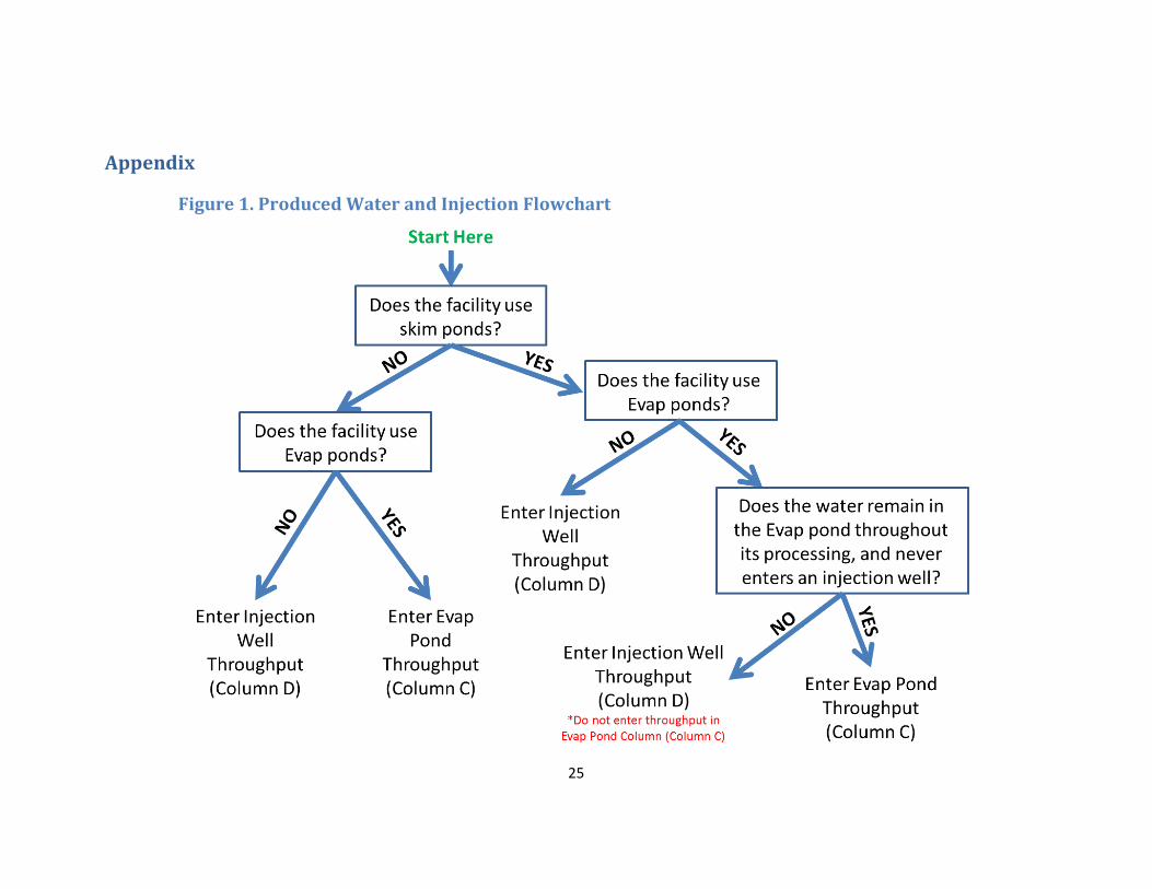
Produced Water and Injection This section is for estimating VOC emissions from produced water ponds and injection wells
using emission factors derived through a mass balance approach developed by UDAQ’s Permit
Section (see: https://deq.utah.gov/locations/U/uintahbasin/air-agencies-emissions-inventory/ponds-
landfarms-landfills-gaps-filling.htm). For further information about reporting for this tab see Figure
1 in the appendix.
Note: Produced water facilities that skim oil or condensate product from ponds, and send the
collected product to a tank should report the product sent to tanks on the “Tanks” tab.
1. Facility Unique ID # – Provide the Facility Unique ID # that was assigned to the facility in the Facilities tab using the dropdown menu or by manually entering the ID (manual entry of the ID will require user confirmation of entry).
2. Do you operate a skim pond? – Select Yes or No from the drop down menu for the reported facility.
3. Evaporation Pond Annual Throughput – Provide the total amount of product processed through the facility’s evaporation pond(s) annually in bbls/yr (barrels per year). Note: Only report evaporation pond throughput in this field for produced water that remains in an evaporation pond throughout its processing and never enters an injection well. Produced water that was placed into a pond and later transferred to an injection well should be reported in the “Injection Well Throughput” column.
Additionally, if the facility has multiple ponds and they discharge into one another, enter total throughput for the facility not throughput to each individual pond. This

23
avoids double counting emissions (i.e. pond discharges into another one or more but water should only be counted once, not each time it moves from one pond to another).
4. Injection Well Annual Throughput – Provide the total amount of product processed through the facility’s tanks, skim ponds and/or evaporation ponds which was subsequently processed through injection wells(s) annually in bbls/yr (barrels per year). Produced water that was placed into a skim pond and/or evaporation pond and later transferred to an injection well should be reported here, not on the evaporation pond throughput field. If produced water is directly injected without going into a skim or evaporation pond, injection well throughput should still be reported while “Do you operate a skim pond?” is listed as “No” and evaporation pond throughput is left blank or “0”.
5. Emission Factor – The values in these fields were derived through a mass balance approach developed by UDAQ’s Permit Section. This field should not be modified by the user.
6. Emissions – This field contains the formula that calculates the annual VOC emissions (tons/yr). This field should not be modified by the user.
Centrifuges This section is for estimating VOC from centrifuges using an emission factor derived through a
TANKS 4.0.9d run by DAQ's Permit Section (see: https://deq.utah.gov/locations/U/uintahbasin/air-
agencies-emissions-inventory/ponds-landfarms-landfills-gaps-filling.htm).
1. Facility Unique ID # – Provide the Facility Unique ID # that was assigned to the facility in the Facilities tab using the dropdown menu or by manually entering the ID (manual entry of the ID will require user confirmation of entry).
2. Annual Throughput – Provide the total amount of product entering the facility annually in bbls/yr (barrels per year).
3. This field contains a drop-down list of two selections, Controlled, and Uncontrolled. Select the control status that best fits the Centrifuge you are reporting.
4. Percent Control – This field is formatted as a percentage and is where the percent control, provided by the “Control Type”, should be entered. This field will be automatically populated as 0% if “No Control” is selected as the “Control Type”.
5. Emission Factor – The values in these fields were derived through TANKS 4.0.9d run performed by DAQ's Permit Section. This field should not be modified by the user.
6. Emissions – This field contains the formula that calculates the annual emissions (tons/yr). This field should not be modified by the user.
24
Solid Waste Disposal This section is for estimating VOC emissions from solid waste disposal using emission factors
derived through a mass balance approach developed by UDAQ’s Permit Section (see: https://deq.utah.gov/locations/U/uintahbasin/air-agencies-emissions-inventory/ponds-landfarms-
landfills-gaps-filling.htm).
Note: Solid waste disposal emissions should only be estimated from disposal at end use
facilities (not facilities where the waste was generated).
1. Facility Unique ID # – Provide the Facility Unique ID # that was assigned to the facility in the Facilities tab using the dropdown menu or by manually entering the ID (manual entry of the ID will require user confirmation of entry).
7. Annual Throughput – Provide the total amount of product entering the facility annually in kg/yr (kilograms per year). Note: Enter throughput for each disposal site category type (landfill or landfarm) not throughput to each individual disposal site if there is more than one disposal site type at the facility. This avoids double counting emissions.
2. Disposal Site Type – This is a drop-down list containing two disposal site types: Landfarm and Landfill. The user should select the disposal site type for the reported facility.
3. Emission Factor – The values in these fields were derived through a mass balance approach developed by UDAQ’s Permit Section. This field should not be modified by the user.
4. Emissions – This field contains the formula that calculates the annual VOC and (tons/yr). This field should not be modified by the user.
Company Summary The summary tab notes the company total for emissions by pollutant type (PM10, PM2.5, SOx,
NOx, VOC, CO, CH2O) summed from each worksheet. This worksheet is automatically populated
according to inputs on prior worksheets, and should not be modified by the user.
25
Appendix
Figure 1. Produced Water and Injection Flowchart