2018 deck guidelines - nixa
TRANSCRIPT

2018 Typical Deck Details
Based on the 2018 Interna1onal Residen1al Codes

Exterior Decks Requirements R507
Deck. Wood-framed decks shall be in accordance with this section. For decks using materials and conditions not prescribed in the section, refer to Section R301.
Materials. Materials used for the construction of decks shall comply with this section. R507.2
Wood materials. Wood materials shall be No. 2 grade or better lumber, preservative-treated in accordance with Section R317, or approved, naturally durable lumber, and termite protected where required in accordance with Section R318. Where design in accordance with Section R301 is provided, wood structural members shall be designed using the wet service factor defined in AWC NDS. Cuts, notches and drilled holes of preservative-treated wood members shall be treated in accordance with Section R317.1.1. All preservative-treated wood products in contact with the ground shall be labeled for such usage. R507.2.1
Engineered wood products. Engineered wood products shall be in accordance with Section R502. R507.2.1.1
Plastic composite deck boards, stair treads, guards, or handrails. Plastic composite
exterior deck boards, stair treads, guards and handrails shall comply with the requirements of ASTM D7032 and this section. R507.2.2 Labeling. Plastic composite deck boards and stair treads, or their packaging, shall
bear a label that indicates compliance with ASTM D7032 and includes the allowable load and maximum allowable span determined in accordance with ASTM D7032. Plastic or composite handrails and guards, or their packaging, shall bear a label that indicates compliance with ASTM D7032 and includes the maximum allowable span determined in accordance with ASTM D7032.
Flame spread index. Plastic composite deck boards, stair treads, guards, and
handrails shall exhibit a flame spread index not exceeding 200 when tested in accordance with ASTM E84 or UL 723 with the test specimen remaining in place during the test.
Exception: Plastic composites determined to be noncombustible.
Decay resistance. Plastic composite deck boards, stair treads, guards and handrails containing wood, cellulosic or other biodegradable materials shall be decay resistant in accordance with ASTM D7032. R507.2.2.3
Termite resistance. Where required by Section 318, plastic composite deck boards,
stair treads, guards and handrails containing wood, cellulosic or other biodegradable materials shall be termite resistant in accordance with ASTM D7032. R507.2.2.4
Installation of plastic composites. Plastic composite deck boards, stair treads,
guards and handrails shall be installed in accordance with this code and the manufacturer’s instructions. R507.2.2.5

Fasteners and connectors. Metal fasteners and connectors used for all decks shall be in accordance with Section R317.3 and Table R507.2.3. R507.2.3
Flashing. Flashing shall be corrosion-resistant metal or nominal thickness not less than 0.019 inch or
approved nonmetallic material that is compatible with the substrate of the structure and the decking materials.
Alternate materials. Alternative materials, including glass and metals, shall be permitted. Footings. Decks shall be supported on concrete footings or other approved structural systems designed to accommodate all loads in accordance with Section R301. Deck footings shall be sized to carry the imposed loads from the deck structure to the ground as shown in Figure R507.3. The footing depth shall be in accordance with Section R403.1.4. Exception. Free-standing decks consisting of joists directly supported on grade over their entire length.
ITEM MATERIAL MINIMUM FINISH/COATINGALTERNATE
FINISH/COATINGe
Nails and timber rivets
In accordance with ASTM F1667
Hot-dipped galvanized per ASTM A153 Stainless steel, silicon bronze or copper
Boltsc Lag screwsd
(including nuts andwashers)
In accordance with ASTM A307 (bolts), ASTM A563 (nuts), ASTM F844 (washers)
Hot-dipped galvanized per ASTM A153, Class C (Class D for 3/8-inch diameter and less) or mechanically galvanized per ASTM B695, Class 55 or 410 stainless steel
Stainless steel, silicon bronze or copper
Metal connectors
Per manufacturer’s specification
ASTM A653 type G185 zinc coated galvanized steel or post hot-dipped galvanized pe rASTM A123 providing a minimum average coating weight of 2.0 oz./ft2 (total both sides)
Stainless steel
e.Stainless-steel-driven fasteners shall be in accordance with ASTM F1667.
TABLE R507.2.3FASTENER AND CONNECTOR SPECIFICATIONS FOR DECKSa , b
For SI: 1 inch = 25.4 mm, 1 foot = 304.8 mm.a.Equivalent materials, coatings and finishes shall be permitted.b.Fasteners and connectors exposed to salt water or located within 300 feet of a salt water shoreline shall be stainless steel.
d.Lag screws 1/2 inch and larger shall be predrilled to avoid wood splitting per the National Design Specification (NDS) for Wood Construction.
c.Holes for bolts shall be drilled a minimum 1/32 inch and a maximum 1/16 inch larger than the bolt.

Minimum depth. Exterior footings shall be placed not less than 12 inches below the undisturbed ground surface. R403.1.4
• 18” below finished grade • 18” square or 18” round diameter
Deck posts. For single-level wood-framed decks, post sizes shall be 6x6 and a maximum height shall be 14’0”. Exception: Landings and decks less than 30” in height can use 4x4 post. Deck posts to deck footing connection. Where posts bear on concrete footings in accordance with Section R403 and Figure R507.4.1, lateral restraint shall be provided by manufactured connectors or a minimum post embedment of 12 inches in surrounding soils or concrete piers. Other footing systems shall be permitted. R507.4.1
Exception: Where expansive, compressible, shifting or other questionable soils are present, surrounding soils shall not be relied on for lateral support.
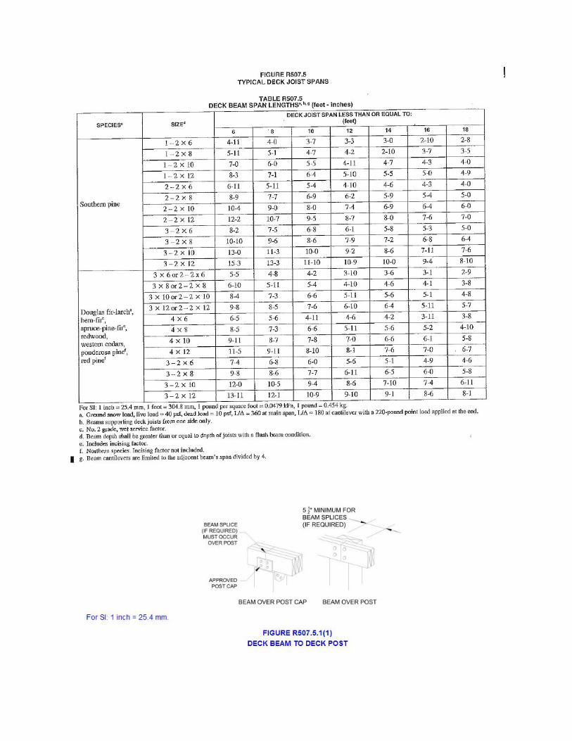
Deck Beams. Maximum allowable spans for wood deck beams, as shown in Figure R507.5 shall be in accordance with Table R507.5. Beam plies shall be fastened with two rows of 10d (3-inch x 0.128-inch) nails minimum at 16 inches on center along each edge. Beams shall be permitted to cantilever at each end up to one-fourth of the allowable beam span. Deck beams of other materials shall be permitted where designed in accordance with accepted engineering practices. R507.5

Deck beam bearing. The ends of beams shall have not less than 1 1/2 inches of bearing on wood or metal and not less than 3 inches of bearing on concrete or masonry for the entire width of the beam. Where multiple –span beams bear on intermediate posts, each ply must have full bearing on the post in accordance with Figures R507.5.1 (1) and R507.5.2 (2) R507.5.1 Deck beam connection to supports. Deck beams shall be attached to supports in a manner capable of transferring vertical loads and resisting horizontal displacement. Deck beam connections to wood posts shall be in accordance with Figures R507.5.1(1) and R507.5.1(2). Manufactured post-to-beam connectors shall be sized for the post and beam sizes. Bolts shall have washers under the head and nut.
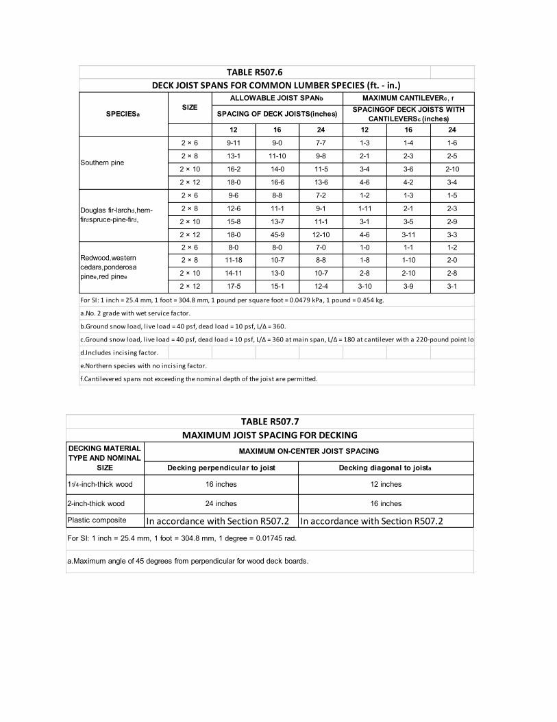
Deck joists. Maximum allowable spans for wood deck joists, as shown in Figure R507.6 shall be in accordance with Table R507.6. The maximum joist spacing shall be limited by the decking materials in accordance with Table R507.37. The maximum joist cantilever shall be limited to one-fourth of the joist span or the maximum cantilever length specified in Table R507.6, whichever is less. R507.6 Deck joist bearing. The ends of joists shall have not less than 1 1/2 inches of bearing on
wood or metal and not less than 3 inches of bearing on concrete or masonry over its entire width. Joists bearing on top of a multiple-ply beam or ledger shall be attached by a mechanical connector. Joist framing into the side of a beam or ledger board shall be supported by approved joist hangers. R507.6.1
Deck joist lateral restraint. Joist ends and bearing locations shall be provided with lateral
resistance to prevent rotation. Where lateral restraint is provided by joist hangers or blocking between joists, their depth shall equal not less than 60 percent of the joist depth. Where lateral restraint is provided by rim joists, they shall be secured to the end of each joist with not fewer than three 10d (3-inch by 0.128-inch) nails OR THREE No. 10x3-inch long wood screws.
Decking. Maximum allowable spacing for joists supporting decking shall be in accordance with Table R507.7. Wood decking shall be attached to each supporting member with not less than two 8d threaded nails tor two No. 8 wood screws. Other approved decking or fastener systems shall be installed in accordance with the manufacturer’s installation requirements. Vertical and lateral supports. Where supported by attachment to an exterior wall, decks shall be positively anchored to the primary structure and designed for both vertical and lateral loads. Such attachment shall not be accomplished by the use of toenails or nails subject to withdrawal. For decks with cantilevered framing members, connection to exterior walls or other framing members shall be designed and constructed to resist uplift resulting from the full live load specified in Table R301.5 acting on the cantilevered portion of the deck. Where positive connection to the primary building structure cannot be verified during inspection, decks shall be self-supporting.
Vertical and lateral supports at band joist. Vertical and lateral supports for decks shall comply with this section. R507.9 Vertical supports. Vertical loads shall be transferred to band joists with ledgers in
accordance with this section. R507.9.1

Ledger details. Deck ledgers shall be a minimum 2-inch by 8-inch nominal.,
pressure-preservative-treated Southern pine, incised pressure-preservative-treated hem-fir, or approved, naturally durable, No. 2 grade or better lumber. Deck ledgers shall not support concentrated loads from beams or girders. Deck ledgers shall not be supported on stone or masonry veneer. R507.9.1.1
Band joist details. Band joists supporting a ledger shall be a minimum 2-inch solid-
sawn, spruce-pine-fir or better lumber or a minimum 1-inch by 9 1/2-inch dimensional, Douglas fir or better, laminated veneer lumber. Band joists shall bear fully on the primary structure capable of supporting all required loads. R507.9.1.2
Ledger to band joist details. Fasteners used in deck ledger connections in
accordance with Table R507.9.1.3(1) shall be hot-dipped galvanized or stainless steel and shall be installed in accordance with Table R507.9.1.3(2) and Figures R507.9.1.3(1) and R507.9.1.3(2). R507.9.1.3
Lateral connection. Lateral loads shall be transferred to the ground or to a structure capable
of transmitting them to the ground. Where the lateral load connection is provided in accordance with Figured R507.9.2(1), hold-down tension devices shall be installed in not less than two locations per deck, within 24 inches of each end of the deck. Each device shall have an allowable stress design capacity of not less than 1,500 pounds. Where the lateral load connections are provided in accordance with Figure R507.9.2(2), the hold-down tension devices shall be installed in not less than four locations per deck, and each device shall have an allowable stress design capacity of not less than 750 pounds. R507.9.2


Decking perpendicular to joist Decking diagonal to joista
11/4-inch-thick wood 16 inches 12 inches
2-inch-thick wood 24 inches 16 inches
Plastic composite In accordance with Section R507.2 In accordance with Section R507.2
a.Maximum angle of 45 degrees from perpendicular for wood deck boards.
DECKING MATERIAL TYPE AND NOMINAL
SIZE
MAXIMUM ON-CENTER JOIST SPACING
TABLE R507.7MAXIMUM JOIST SPACING FOR DECKING
For SI: 1 inch = 25.4 mm, 1 foot = 304.8 mm, 1 degree = 0.01745 rad.
12 16 24 12 16 24
2 × 6 9-11 9-0 7-7 1-3 1-4 1-6
2 × 8 13-1 11-10 9-8 2-1 2-3 2-5
2 × 10 16-2 14-0 11-5 3-4 3-6 2-10
2 × 12 18-0 16-6 13-6 4-6 4-2 3-4
2 × 6 9-6 8-8 7-2 1-2 1-3 1-5
2 × 8 12-6 11-1 9-1 1-11 2-1 2-3
2 × 10 15-8 13-7 11-1 3-1 3-5 2-9
2 × 12 18-0 45-9 12-10 4-6 3-11 3-3
2 × 6 8-0 8-0 7-0 1-0 1-1 1-2
2 × 8 11-18 10-7 8-8 1-8 1-10 2-0
2 × 10 14-11 13-0 10-7 2-8 2-10 2-8
2 × 12 17-5 15-1 12-4 3-10 3-9 3-1
d.Includes incising factor.
TABLE R507.6
SPECIESaSIZE
ALLOWABLE JOIST SPANb MAXIMUM CANTILEVERc , f
SPACING OF DECK JOISTS(inches) SPACINGOF DECK JOISTS WITH CANTILEVERSc (inches)
f.Cantilevered spans not exceeding the nominal depth of the joist are permitted.
Southern pine
Douglas fir-larchd,hem-firdspruce-pine-fird,
Redwood,western cedars,ponderosa pinee,red pinee
DECK JOIST SPANS FOR COMMON LUMBER SPECIES (ft. - in.)
For SI: 1 inch = 25.4 mm, 1 foot = 304.8 mm, 1 pound per square foot = 0.0479 kPa, 1 pound = 0.454 kg.
a.No. 2 grade with wet service factor.
b.Ground snow load, l ive load = 40 psf, dead load = 10 psf, L/Δ = 360.
c.Ground snow load, l ive load = 40 psf, dead load = 10 psf, L/Δ = 360 at main span, L/Δ = 180 at cantilever with a 220-pound point load applied to end.
e.Northern species with no incising factor.

Decking perpendicular to joist Decking diagonal to joista
11/4-inch-thick wood 16 inches 12 inches
2-inch-thick wood 24 inches 16 inches
Plastic composite In accordance with Section R507.2 In accordance with Section R507.2
a.Maximum angle of 45 degrees from perpendicular for wood deck boards.
DECKING MATERIAL TYPE AND NOMINAL
SIZE
MAXIMUM ON-CENTER JOIST SPACING
TABLE R507.7MAXIMUM JOIST SPACING FOR DECKING
For SI: 1 inch = 25.4 mm, 1 foot = 304.8 mm, 1 degree = 0.01745 rad.


GUARDREQUIREMENTSAll decks greater than 30” above grade are required to have a guard. If you are providing a guard when one is not required, it must meet these requirements. All guards shall be constructed in strict conformance with details herein; any deviations require a plan submission.
Any pre-fabricated wood, plastic, composite or manufactured guard system purchased from a home center store, lumber company or similar will also require a plan submission.

ONLY THOSE PLASTIC, COMPOSITE OR MANUFACTURED GUARD SYSTEMS LISTED BY AN ACCREDITED TESTING AGENCY ARE APPROVED FOR USE IN THE CITY OF NIXA.
Guard Post To Rim Joist: Use one of the options shown in FIGURE 26 through FIGURE 28 to attach a guard post to a rim joist. See FIGURE 10 for rim joist-to-deck joist and decking-to-rim joist attachment requirements.
Option 1: As shown in FIGURE 26, guard posts are attached to the inside face of the rim joists, to attach guard post to the outside of the rim joist, see OPTION 2 or OPTION 3.
Option 2: As shown in FIGURE 27, hold-down anchors must be installed to attach the rim joist to the deck joists. Hold-down anchors must be galvanized with 1.85 oz/sf of zinc (G-185 coating) or shall be stainless steel. There shall be a minimum of two bolts at the anchors’ attachment to the joist. Look for model number HD2A in a Zmax coating from Simpson Strong-Tie, model number HD2A in a Triple Zinc coating from USP, or the hot-dipped galvanized DeckLok by Morse Technologies. Other hold-down anchor models meeting the minimum requirements ma also be used.

Option 3: As shown in FIGURE 28, the rim joist must be fastened to deck joists with two 20 gage stud tie plates attached per the manufacturer’s instructions with hot-dipped galvanized or stainless steel fasteners. Stud tie plates must be galvanized with 1.85 oz/sf of zinc (G-185 coating) or shall be stainless steel. Look for model number SP1 in a Zmax coating from Simpson Strong-Tie or model number SPT22 in a Triple Zinc coating from USP. Other tie plate models meeting the minimum requirements may also be used.

STAIRREQUIREMENTS
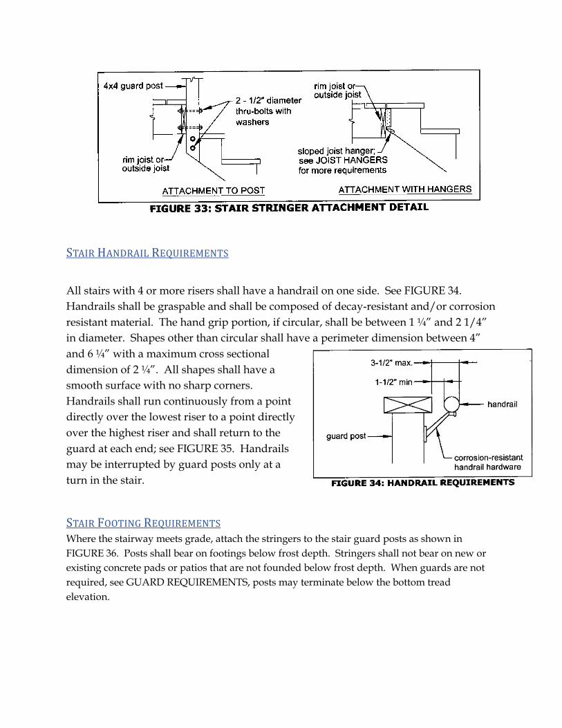
Stairs, stair stringers and stair guard shall meet the requirements shown in FIGURE 29 through FIGURE 36. All stringers shall be 2x12. Stair stringers shall not span more than the dimensions shown in FIGURE 30. If the stringer span exceeds these dimensions, then an intermediate landing will be required. All intermediate stair landings must be designed and constructed as a free-standing deck using the details in this package.

STAIRHANDRAILREQUIREMENTS
All stairs with 4 or more risers shall have a handrail on one side. See FIGURE 34. Handrails shall be graspable and shall be composed of decay-resistant and/or corrosion resistant material. The hand grip portion, if circular, shall be between 1 ¼” and 2 1/4” in diameter. Shapes other than circular shall have a perimeter dimension between 4” and 6 ¼” with a maximum cross sectional dimension of 2 ¼”. All shapes shall have a smooth surface with no sharp corners. Handrails shall run continuously from a point directly over the lowest riser to a point directly over the highest riser and shall return to the guard at each end; see FIGURE 35. Handrails may be interrupted by guard posts only at a turn in the stair.
STAIRFOOTINGREQUIREMENTSWhere the stairway meets grade, attach the stringers to the stair guard posts as shown in FIGURE 36. Posts shall bear on footings below frost depth. Stringers shall not bear on new or existing concrete pads or patios that are not founded below frost depth. When guards are not required, see GUARD REQUIREMENTS, posts may terminate below the bottom tread elevation.

STAIRLIGHTINGREQUIREMENTSStairways shall have a light source located at the top landing such that all stairs and landings are illuminated. The light switch shall be operated from inside the house. However, motion detected or timed switches are acceptable.