contentsetctracker.schneider-electric.com/.../service_manual.pdf · 2019-09-25 · 4. contamination...
TRANSCRIPT


TBI AF/IMS001/R3 Installation, Commissioning, Operation & Maintenance of Transformer
1 | P a g e
Contents
WARRANTY TERMS & CONDITIONS ............................................................................................ 7
WARRANTY TERMS AND CONDITIONS .................................................................................................................................... 8
SECTION-1 ................................................................................................................................ 12
ENVIRONMENT, HEALTH & SAFETY .......................................................................................... 12
1. ENVIRONMENT, HEALTH & SAFETY ................................................................................................................................. 13
1.1 ELECTRICAL SAFETY ..................................................................................................................................................... 13
1.2 HAZARDOUS SUBSTANCES .......................................................................................................................................... 14
1.3 ENVIRONMENTAL HAZARDS DUE TO OIL SPILLAGE & FIRE CONSEQUENT TO FAILURE OF TRANSFORMER AT
SITE ................................................................................................................................................................................... 14
1.4 CONTROL OF OIL SPILLAGE .......................................................................................................................................... 14
1.5 CONTROL OF FIRE .......................................................................................................................................................... 15
1.6 PRECAUTIONS AGAINST FIRE ...................................................................................................................................... 15
1.7 DO'S AND DON'TS FOR SAFETY MEASURES / PRECAUTIONS ................................................................................. 15
1.8 TROUBLE SHOOTING ..................................................................................................................................................... 19
SECTION-2 ................................................................................................................................ 20
GENERAL INTRODUCTION ........................................................................................................ 20
2. GENERAL INTRODUCTION ................................................................................................................................................. 21
2.1 TRANSFORMER CONSTRUCTION ................................................................................................................................. 21
2.1.1 CORE ....................................................................................................................................................................................... 21
2.1.2 WINDINGS .............................................................................................................................................................................. 21
2.1.3 COOLING ................................................................................................................................................................................ 21
2.1.4 TANK & COVER ..................................................................................................................................................................... 22
2.1.5 CONSERVATOR .................................................................................................................................................................... 22
2.1.6 PRESSURE RELIEF DEVICE .............................................................................................................................................. 22
2.1.7 GAS & OIL ACTUATED (BUCHHOLZ) RELAY ................................................................................................................. 23
2.1.8 SILICAGEL BREATHER ....................................................................................................................................................... 23
2.1.9 WINDING TEMPERATURE INDICATOR ........................................................................................................................... 24

TBI AF/IMS001/R3 Installation, Commissioning, Operation & Maintenance of Transformer
2 | P a g e
2.1.10 OIL TEMPERATURE INDICATOR ...................................................................................................................................... 24
2.1.11 BUSHINGS .............................................................................................................................................................................. 24
2.1.12 TAP CHANGER ...................................................................................................................................................................... 25
2.1.13 CONTROL & MONITORING SYSTEM ............................................................................................................................... 25
2.1.14 FIRE DETECTION & FIRE FIGHTING SYSTEM .............................................................................................................. 25
2.2 TRANSPORT & PACKING & DESPATCH........................................................................................................................ 26
2.2.1 GENERAL ................................................................................................................................................................................ 26
2.2.2 PACKING ................................................................................................................................................................................. 27
2.2.3 LIFTING ................................................................................................................................................................................... 27
2.2.4 JACKING ................................................................................................................................................................................. 28
2.2.5 IMPACT RECORDERS ......................................................................................................................................................... 28
a) MECHANICAL TYPE IMPACT RECORDERS ...................................................................................................................... 28
b) SHOCK DETECTOR ................................................................................................................................................................. 29
2.2.6 STORAGE ............................................................................................................................................................................... 31
2.2.7 SHIPMENT OF OIL ................................................................................................................................................................ 31
2.2.8 RECEIVING MAIN UNIT AND ACCESSORIES ................................................................................................................ 32
2.2.9 UNLOADING OF MAIN UNIT ............................................................................................................................................... 32
2.2.10 UNPACKING AND INSPECTION OF ACCESSORIES .................................................................................................... 33
2.2.11 STORAGE OF MAIN BODY ................................................................................................................................................. 33
2.2.12 PLACING IN POSITION ........................................................................................................................................................ 37
SECTION-3 ................................................................................................................................ 38
INSTALLATION .......................................................................................................................... 38
3. INSTALLATION ..................................................................................................................................................................... 39
3.1 LOCATION ........................................................................................................................................................................ 39
3.2 FOUNDATION ................................................................................................................................................................... 39
3.3 PROVISIONS FOR OIL DRAINING .................................................................................................................................. 39
3.4 ASSEMBLY OF DISMANTLED COMPONENTS .............................................................................................................. 39
3.4.1 MAIN TANK ............................................................................................................................................................................. 39
3.4.2 BUSHINGS .............................................................................................................................................................................. 39
TBI AF/IMS001/R3 Installation, Commissioning, Operation & Maintenance of Transformer
3 | P a g e
3.4.3 CONSERVATOR & MOG...................................................................................................................................................... 40
3.4.4 BUCHHOLZ RELAY ............................................................................................................................................................... 42
3.4.5 BREATHERS .......................................................................................................................................................................... 42
3.4.6 RADIATORS ........................................................................................................................................................................... 42
3.4.7 MARSHALLING BOX ............................................................................................................................................................. 43
3.4.8 CABLE BOX ............................................................................................................................................................................ 43
3.5 AIR RELEASE ................................................................................................................................................................... 43
3.6 OIL SAMPLING AND FILTERING ..................................................................................................................................... 43
3.7 PRECAUTION TO MAINTAIN QUALITY .......................................................................................................................... 44
3.8 ERECTION OF COOLER BANK ....................................................................................................................................... 45
3.9 PRESSURE RELIEF DEVICE ........................................................................................................................................... 46
SECTION-4 ................................................................................................................................ 47
FITTINGS & ACCESSORIES ....................................................................................................... 47
4. FITTINGS & ACCESSORIES ................................................................................................................................................ 48
4.1 RATING & TERMINAL MARKING PLATE (R & D Plate) .................................................................................................. 48
4.2 TAP CHANGING ARRANGEMENT .................................................................................................................................. 48
(i) Off-Circuit Switch ............................................................................................................................................................................ 48
(ii) Off-Circuit Ratio Changing links ................................................................................................................................................... 48
(iii) On-Load Tap Changer ................................................................................................................................................................... 48
4.3 EARTHING TERMINALS .................................................................................................................................................. 48
4.4 LIFTING LUGS .................................................................................................................................................................. 48
4.5 VALVES ............................................................................................................................................................................. 49
4.6 BUSHINGS ........................................................................................................................................................................ 49
a) Oil Communicating Type ............................................................................................................................................................... 49
b) Condenser Bushings ..................................................................................................................................................................... 49
4.7 CABLE BOXES ................................................................................................................................................................. 50
4.8 BUSDUCT ......................................................................................................................................................................... 50
4.9 MARSHALLING BOX ........................................................................................................................................................ 51
4.10 ERECTION OF HV TURRETS AND BUSHINGS ............................................................................................................. 51

TBI AF/IMS001/R3 Installation, Commissioning, Operation & Maintenance of Transformer
4 | P a g e
4.11 TEMPERATURE INDICATORS ........................................................................................................................................ 52
4.12 OLTC DRIVE MECHANISM .............................................................................................................................................. 53
4.13 INSTRUCTIONS REGARDING USAGE OF GASKETS ................................................................................................... 53
4.14 CHECKING LEAK RATE UNDER VACUUM .................................................................................................................... 54
4.15 INSULATION OF CORE AND FRAME TO TANK ............................................................................................................ 54
4.16 VACUUM OIL INJECTION ................................................................................................................................................ 54
4.17 TOUCH UP PAINTING AT SITE ....................................................................................................................................... 55
4.18 MIXING OF TRANSFORMER OIL .................................................................................................................................... 55
4.19 INSULATION DRY OUT AT SITE ..................................................................................................................................... 55
i) HOT OIL CIRCULATION .............................................................................................................................................................. 55
ii) TRANSFORMER OIL PUMP ........................................................................................................................................................ 57
SECTION-5 ................................................................................................................................ 58
COMMISSIONING ...................................................................................................................... 58
5. COMMISSIONING ................................................................................................................................................................. 59
5.1 INSPECTION AND MAINTENANCE LOG SHEET ........................................................................................................... 59
5.2 PHYSICAL CHECKS ......................................................................................................................................................... 59
5.3 INSULATION RESISTANCE CHECK ............................................................................................................................... 60
5.4 RATIO TESTS ................................................................................................................................................................... 60
5.5 VECTOR GROUP TESTS ................................................................................................................................................. 60
5.6 MAGNETIC BALANCE TEST ........................................................................................................................................... 60
5.7 SHORT CIRCUIT IMPEDENCE ........................................................................................................................................ 60
5.8 WINDING RESISTANCE MEASUREMENT ..................................................................................................................... 61
5.9 OPERATION CHECKS ..................................................................................................................................................... 61
5.10 BUCHHOLZ RELAY OPERATION .................................................................................................................................... 61
SECTION-6 ................................................................................................................................ 62
6. TRANSFORMER ACCESSORIES ........................................................................................................................................ 63
6.1 TEMPERATURE INDICATOR .......................................................................................................................................... 63
6.2 GAS OPERATED (BUCHHOLZ) RELAYS........................................................................................................................ 66
6.3 OIP CONDENSER TYPE BUSHINGS .............................................................................................................................. 68

TBI AF/IMS001/R3 Installation, Commissioning, Operation & Maintenance of Transformer
5 | P a g e
6.4 SILICA GEL BREATHER .................................................................................................................................................. 75
6.5 MAGNETIC OIL LEVEL GAUGE: (MOLG) ....................................................................................................................... 77
6.6 PRESSURE RELIEF VALVE ............................................................................................................................................ 80
6.7 COOLING FANS ............................................................................................................................................................... 82
6.8 FLEXIBLE SEPARATOR (AIR CELL) ............................................................................................................................... 83
6.9 OIL TO WATER HEAT EXCHANGER .............................................................................................................................. 87
6.10 BCD TPI ............................................................................................................................................................................ 91
6.11 DGPT2 / DMCR RELAY .................................................................................................................................................... 91
6.12 On-line DGA ...................................................................................................................................................................... 92
6.13 AVR RELAY (AUTOMATIC VOLTAGE REGULATING RELAY) ...................................................................................... 93
6.14 A-EBERLE RELAY ............................................................................................................................................................ 94
SECTION-7 ................................................................................................................................ 95
OPERATION & MAINTENANCE .................................................................................................. 95
7. OPERATION & MAINTENANCE ........................................................................................................................................... 96
7.1 PERIODIC INSPECTION SCHEDULE FOR POWER TRANSFORMER ......................................................................... 97
7.2 DISSOLVED GAS ANALYSIS ........................................................................................................................................... 98
7.3 OIL SAMPLING ............................................................................................................................................................... 102
7.4 WINDING TEMPERATURE INDICATOR TESTS ........................................................................................................... 104
7.5 BUCHHOLZ RELAY FUNCTIONAL TEST ...................................................................................................................... 105
7.6 TAP CHANGER OPERATION ........................................................................................................................................ 106
7.7 OIL FILTRATION ............................................................................................................................................................. 107
7.8 REMOVING AND REFITTING CONSERVATOR & BUCHHOLZ RELAY PIPELINE ..................................................... 107
7.9 REMOVING AND REFITTING RADIATOR..................................................................................................................... 109
7.10 REMOVING & REFITTING BUSHINGS .......................................................................................................................... 110
SECTION-8 .............................................................................................................................. 113
PRODUCT END-OF-LIFE INSTRUCTIONS ................................................................................ 113
8. PURPOSE ........................................................................................................................................................................... 114
APPENDICES ........................................................................................................................... 118
APPENDIX – A ERECTION CHECK LIST ................................................................................................................................ 119
TBI AF/IMS001/R3 Installation, Commissioning, Operation & Maintenance of Transformer
6 | P a g e
APPENDIX -B PRE-COMMISSIONING CHECKS .................................................................................................................... 119
APPENDIX -C TEST RESULTS ................................................................................................................................................ 119
APPENDIX –D CHECKS BEFORE ENERGIZATION ............................................................................................................... 119
APPENDIX E - ADDITIONAL CHECKS FOR PRECOMMISSIONING ..................................................................................... 119
OIL VERIFICATION SLIP .......................................................................................................................................................... 119
NATIONAL AND INTERNATIONAL STANDARDS ...................................................................... 120
NATIONAL AND INTERNATIONAL STANDARDS APPLICABLE TO POWER TRANSFORMER AND ALLIED PRODUCTS 121
I. INDIAN NATIONAL STANDARDS ............................................................................................................................................ 121
(i) POWER TRANSFORMERS ................................................................................................................................................... 121
(ii) MATERIALS, FITTINGS AND ACCESSORIES OF POWER TRANSFORMERS ......................................................... 121
(iii) INSTRUMENT TRANSFORMERS ........................................................................................................................................ 123
(iv) TRANSFORMER BUSHING................................................................................................................................................... 123
(v) TRANSFORMER OIL AND OIL TESTING ........................................................................................................................... 124
(vi) INSULATION CO ORDINATION AND HIGH VOLTAGE TESTING ................................................................................. 124
II. IEC STANDARDS ........................................................................................................................................................................ 124
NOTES ....................................................................................................................................................................................... 127
HAPPY TO HELP ...................................................................................................................................................................... 131

TBI AF/IMS001/R3 Installation, Commissioning, Operation & Maintenance of Transformer
7 | P a g e
WARRANTY TERMS & CONDITIONS

TBI AF/IMS001/R3 Installation, Commissioning, Operation & Maintenance of Transformer
8 | P a g e
WARRANTY TERMS AND CONDITIONS
Warranty conditions are those conditions which shall be complied fully to avail warranty benefits. Violation of these conditions lead to warranty suspension before due date mentioned in warranty certificate.
1. Recommendations & requirements mentioned in this Manual must be fully complied. In case of any issue or a situation where certain requirement or recommendation cannot be fulfilled, Schneider Electric-Transformer division (hereafter referred as SE-TBI) shall be consulted before putting the product in service.
2. Transformer & its accessories shall be carefully handled so as not to damage external parts or inside assembly as this can lead to bodily damage and/or electrical failure.
3. During warranty period, transformer or a part of transformer shall not be opened for repair or internally inspected by third party in absence of SE-TBI Engineer. SE-TBI Transformers are despatched with a seal in one corner of tank cover bolt. Opening of tank cover or damage of this seal in absence of SE-TBI Engineer shall lead to warranty discontinuation. Refer Fig (i) on Page-10.
4. Contamination of oil with water, moisture, dust etc shall be prevented during storage, erection & commissioning. Product failure attributed to these contaminations shall lead to warranty discontinuation.
5. In case of delay in commissioning for more than six months in oil-filled transformers, oil level & BDV of oil must be monitored once in a month to ensure quantity & quality of oil during storage. Oil level must be visible in tank oil level gauge (TOLG) to ensure inside assembly is immerged in oil. Failure attributed to non-compliance of it will cause warranty discontinuation.
6. Insulation resistance of all windings shall be as recommended in this manual before charging of transformer.(Refer Clause 5.3 in Section-5)
7. CT terminals shall be shorted if not in use. Refer Fig (ii) on Page-10
8. Transformer is not self-protective equipment, hence, needs to be protected from external faults. Necessary protective systems as recommended by applicable standard (statutory & regulatory requirements of respective utilities/authority) shall be provided in duly operational condition. Latest version of IEEE Std. C37.91 may also be referred for further details.
9. Erection & commissioning test results shall be shared with SE-TBI & consent for commissioning shall be obtained before charging. (Refer Appendix A,B,C,D & E)
10. Number of operation of OLTC shall be monitored & oil filtration/ servicing/ overhauling shall be done as per recommendation in OEM service manual & as mentioned in this manual. (Refer Clause 2.1.12 in Section-2) and refer Fig (iii) for OLTC Counter and Fig (iv) for TPI counter.
11. Failure of transformer caused due to non-functioning/ improper-healthiness of protective device in case of occurrence of fault shall void the warranty of the product.

TBI AF/IMS001/R3 Installation, Commissioning, Operation & Maintenance of Transformer
9 | P a g e
12. Failure of transformer caused due to improper service conditions e.g. lack of routine/ preventive maintenance, overloading, overvoltage etc shall void the warranty of product.
13. Erection must be done by competent agency/ certified by SE-TBI or in supervision of SE-TBI.
14. Safe external electrical clearances shall be maintained as per applicable regulatory requirements and as mentioned in OGA.
15. Ensure complete air is vented from all air release plugs before charging. Refer Fig (v),(vi) and (vii) on Page-11.
16. Ensure earthing of transformer as per IE / IEC guidelines.
17. Warranty voids if transformer fails due to poor maintenance of OLTC. (Refer OLTC OEM Service Manual for details)
18. In case of any tripping in Buchholz relay, PRV, OSR & DMCR relay, SE-TBI must be informed before re-charging. Multiple re-charging without detailed investigation may leads to failure of transformer windings. In that case, warranty shall void.
19. Off circuit tap changer must not be operated during energized condition. Refer Fig (viii) on Page-11
20. Failure or damage of component due to incorrect electrical connection shall not be covered under applicable warranty & will be repaired or replaced on chargeable basis.
21. Any modification in product at site which results into deviation from Outline General Arrangement will void the warranty.
22. Limitation of Liability : SE-TBI shall not be held responsible for any claims or consequential damages, loss of profit, loss of revenue, loss of production, disturbances in the grid and loss of property. Aggregate liabilities of SE-TBI for direct damages shall be limited to the payment received as on date and shall not exceed PO value in any circumstances.
23. Consequential Damages : SE-TBI shall not be made responsible /liable for any damages, whether direct or indirect, special, incidental or consquential and or losses, such as loss of profit, loss of production, loss of capacity usage etc. or any other kind not defined herein before including any expenses incurred or to be incurred, arising out any defect in or failure of the equipment of services thus supplied /provided.
------ X ------

TBI AF/IMS001/R3 Installation, Commissioning, Operation & Maintenance of Transformer
10 | P a g e
Fig (i)
Transformer top cover seal
Fig (ii)
CT Terminal shorting link
Fig (iii)
OLTC Counter reading in DM
Fig (iv)
OLTC Counter reading in TPI

TBI AF/IMS001/R3 Installation, Commissioning, Operation & Maintenance of Transformer
11 | P a g e
Fig (v)
Top cover air release
Fig (vi)
Buchholz Relay air release
Fig (vii)
Radiator air release
Fig (viii)
Off-Ciruited Tap Changer

TBI AF/IMS001/R3 Installation, Commissioning, Operation & Maintenance of Transformer
12 | P a g e
SECTION-1
ENVIRONMENT, HEALTH & SAFETY

TBI AF/IMS001/R3 Installation, Commissioning, Operation & Maintenance of Transformer
13 | P a g e
1. ENVIRONMENT, HEALTH & SAFETY
Even though the manufacturer of the transformer has put every effort to comply with the rules and regulations applicable to the safe operation of the transformer, the equipment described in this manual is safe to use provided that:
• It is installed in a location suitable for its designed purpose.
• The installation is done by qualified and competent persons.
• The installed equipment is operated and maintained in accordance with the manufacturer's instructions by qualified and competent persons familiar with the type of equipment involved and its working environment.
• All work is done competently and in accordance with good engineering practices and in a manner, which is not hazardous either to personnel or to equipment.
• The recommended pre-commissioning checks are done before energising the transformer.
• The operation of protective systems and devices for the transformer are checked regularly.
• Neglect or deliberate overriding of protection system or device could allow a minor problem to develop into a major problem resulting in total loss of the transformer, damage to other equipment and injury to personnel.
• Prolonged operation under over load, over voltage or over excitation condition can have a seriously detrimental effect on the life of equipment. The pressure relief devices are designed to eject liquid, which is likely to be very hot in the event of a fault developing within the transformer.
• Equipment such as pressure relief devices incorporates heavy springs in compression. If the equipment is dismantled without due safeguard, damage and /or injury may result.
• The internal atmosphere of a transformer tank, if N2 filled, is replaced by breathable dry air of dew point less than –400 C for a minimum period of twenty-four hours.
1.1 ELECTRICAL SAFETY
The following hazards are commonly associated with the installation, operation and maintenance of electrical equipment
• Existence of AC and DC voltage.
• Possible existence of toxic hazards associated with material used in the construction of electronic components, cleaning agent and solvents.
• Electric shock due to incorrect earthing, moisture on insulation, bad engineering or working practices.
• Fire or burn out due to incorrect setting or over load or protective devices, incorrect cables or fuses, insufficient ventilation or incorrect operating voltage.

TBI AF/IMS001/R3 Installation, Commissioning, Operation & Maintenance of Transformer
14 | P a g e
• Short circuit flash over due to dust or moisture on insulation or short circuit on live conductors.
• If the secondary of a current transformer is disconnected, a dangerously high voltage can be induced in the circuit. If the secondary circuit of a current transformer is to be disconnected it must be shorted by a link capable of carrying the rated current.
• Do not apply any voltage or even high voltage megger when the equipment is under vacuum.
1.2 HAZARDOUS SUBSTANCES
➢ TRANSFORMER OIL
• Normally, transformer oil presents no hazard to health. However, serious neglect may affect the skin and cause irritation.
• Oil is a hydrocarbon and will burn. Carbon dioxide, dry chemical, foam or water fog are proper extinguish agents.
➢ MERCURY
• Mercury switches or thermometers containing mercury should be handled carefully. Mercury vapour can be hazardous over a period of time, especially in poorly ventilated room.
1.3 ENVIRONMENTAL HAZARDS DUE TO OIL SPILLAGE & FIRE CONSEQUENT TO FAILURE OF TRANSFORMER AT SITE
Oil spillage from Transformer tank, bushing, pipe joints etc. may cause the source of major fires. It is recommended that Transformer shall be inspected daily for the oil spillage.
The general CBIP recommendations for the Transformer installation are:
Soak pits
Drain pits
Barrier walls
Fire detection system
Fire hydrant system
1.4 CONTROL OF OIL SPILLAGE
• Responsibility: Respective operator of Sub station
• Keep a track of the maintenance schedule of Transformer & ensure that the required routine & preventive maintenance are done as per the schedule
• On noticing any leakages from the Transformer immediately place a tray /container to collect the spillage and inform the maintenance department for immediate corrective action (for example replacement of gasket etc.). Oil shall not be allowed to fall on to ground.

TBI AF/IMS001/R3 Installation, Commissioning, Operation & Maintenance of Transformer
15 | P a g e
• In case any leakage to ground take place, remove the same with cotton/cloth/ saw dust.
• In case large scale spillage immediately inform the shift in charge & start collecting the spilled oil to suitable container and assess the risk of continuous operation of the Transformer
1.5 CONTROL OF FIRE
• It is necessary to check the healthiness of the Transformer fire protection system regularly so that the fire risk can be minimized
• There shall not be any oil leakage.
• During hot oil circulation in the Transformer keep fire extinguisher ready near the Transformer, all the combustible materials shall be kept at a safe distance.
• Terminal connector, Fuses shall be checked against spark.
• Condition of Transformer oil shall be checked regularly
• Proper Housekeeping near Transformer may help to reduce the risk of fire.
• Proper firefighting system as per CBIP recommendation shall be installed near Transformer. Regular inspection & maintenance to be done on the Firefighting system.
1.6 PRECAUTIONS AGAINST FIRE
• Welding on oil filled Transformer shall be carried out if unavoidable, as per the instructions of the Manufacturer.
• Hot oil circulation shall be carried out only under the round the clock supervision to prevent chances of fire on lagging materials etc.
1.7 DO'S AND DON'TS FOR SAFETY MEASURES / PRECAUTIONS
DO'S
➢ Insulating oil and insulation of windings and connections are inflammable. Watch for fire hazards.
➢ Before entering inside the Transformer, replace Nitrogen gas completely with air if it was transported with nitrogen gas inside.
➢ Make sure that nothing is kept inside the pockets before one enters inside the main unit. Also take off the wristwatches and shoes.
➢ List up all the tools and materials to be taken inside and check it after coming out to make sure that no tools are left inside.
➢ There must be a protective guard for lamp to be taken inside.
➢ Keep inspection covers open for supply of fresh air when someone is working inside.

TBI AF/IMS001/R3 Installation, Commissioning, Operation & Maintenance of Transformer
16 | P a g e
➢ When one person is working inside, second person must be available outside for emergency help.
➢ Use rings spanners and tie them to the wrist of the person or somewhere outside the tank.
➢ Be careful during connections where bolted joints are involved so that nut, washers etc. are not dropped inside the tank.
➢ De-energise the unit by circuit breakers and line switches while working on energised unit.
➢ Check the diaphragm of explosion vent and replace it if cracked.
➢ Attach the caution tags "DO NOT OPERATE THE SWITCHES" while working on units, which are energised.
➢ Firefighting equipment should be checked regularly and should have sufficient quantity of extinguisher.
➢ Transformer tank, control cabinets etc. as well as oil treatment equipment shall be connected with permanent earthing system of the station.
➢ Check and thoroughly investigate the transformer whenever any alarm or protective device is operated.
➢ Check air cell in conservator.
➢ Attend leakage on the bushings.
➢ Examine the bushings for dirt deposits and clean them periodically.
➢ Check the oil in transformer and OLTC for dielectric strength and moisture content and take suitable action for restoring quality.
➢ Check the oil level in oil cup and ensure air passages are free in breather. If oil is less fill the oil up to the mark level.
➢ If inspection covers are removed or any gasket joint is to be tightened, then tighten the bolts evenly to avoid uneven pressure.
➢ Check and clean the relay and alarm contacts. Check also their operation and accuracy and if required change the setting.
➢ Check the protection circuits periodically.
➢ Check the pointers of all gauges for their free movement.
➢ Clean the oil conservator thoroughly before erecting.
➢ Check the OTI and WTI pockets and replenish the oil if required.
➢ Gas filled storage of transformer at site should be limited to a maximum of 3 months.
➢ Check the door seal of the Marshalling box. Change the rubber lining if required.

TBI AF/IMS001/R3 Installation, Commissioning, Operation & Maintenance of Transformer
17 | P a g e
➢ Ensure proper tightness of top terminal of condenser bushings to avoid entry of rainwater.
➢ Check oil level in condenser bushing, any discrepancy should be reported immediately to the manufacturer.
➢ Do jacking only at jacking pad.
DON'TS
➢ Do not take any fibrous material such as cotton waste inside while repairing.
➢ Do not drop any tools / material in side.
➢ Do not stand on leads / cleats.
➢ Do not weld, braze or solder inside the tank.
➢ Do not weld anything to the tank wall from outside.
➢ Do not weld anything to the conservator vessel if Air cell bag is inside.
➢ Do not smoke near the transformer.
➢ Do not use fibrous material for cleaning as it can deteriorate the oil when mixed with it.
➢ Do not energise without thorough investigation of the transformer whenever any alarm of protection has operated.
➢ Do not re-energise the transformer unless the Buchholz gas is analysed.
➢ Do not re-energise the transformer without conducting all pre-commissioning checks. The results must be compared with factory test results.
➢ Do not handle the off circuit tap switch when the transformer is energised.
➢ Do not energise the transformer unless the off circuit tap switch handle is in locked position.
➢ Do not leave off circuit tap switch handle unlocked.
➢ Do not use low capacity lifting jacks / slings on transformer for jacking / slinging.
➢ Do not change the setting of WTI and OTI alarm and trip frequently. Setting should be done as per manufacturer's instructions.
➢ Do not leave any connection loose.
➢ Do not meddle with the protection circuits.
➢ Do not leave marshalling box doors open, they must be locked.
➢ Do not switch off the heater in marshalling box except to be periodically cleaned.

TBI AF/IMS001/R3 Installation, Commissioning, Operation & Maintenance of Transformer
18 | P a g e
➢ Do not allow unauthorised entry near the transformer.
➢ Do not close any valve in pump circuit for taking stand by pump and motor into circuit.
➢ Do not allow water pressure to exceed the oil pressure in oil to water heat exchangers.
➢ Do not mix transformer oils of different make/ base, unless oil is new and conforms fully to IS: 335.
➢ Do not continue with pink (wet) silica gel, this should immediately be changed or reactivated.
➢ Do not store transformer in gas filled condition for more than three months after reaching site. If storage is required for longer duration, the main body should be filled up with oil.
➢ Do not leave tertiary terminals unprotected outside the tank.
➢ Do not allow WTI / OTI temperature to exceed 70°C during dry out of transformer and filter machine temperature beyond 75°C
➢ Do not parallel transformers, which do not fulfil the conditions for paralleling.
➢ Do not over load the transformers beyond limit specified in IS: 6600.
➢ Do not leave secondary terminals of any CT open.
➢ Do not measure insulation resistance by using megger when the transformer is under vacuum.
➢ Do not stand on any vessel, which is under vacuum.

TBI AF/IMS001/R3 Installation, Commissioning, Operation & Maintenance of Transformer
19 | P a g e
1.8 TROUBLE SHOOTING
Following table shows some of the symptoms, possible causes and remedies in case of abnormal situations: –
ABNORMAL OPERATING CONDITIONS
TROUBLE CAUSE REMEDY
Over voltage Change the circuit voltage or transformer
connections to avoid over excitation.
Over current
If possible, reduce load. Heating can be reduced
by improving power factor of load. Check parallel
circuits for circulating currents, which may be
caused by improper ratios or impedances.
High ambient temperature Either improve ventilation or relocate transformer
in lower ambient temperature.
Insufficient cooling If unit is artificially cooled, make sure cooling is
adequate.
Low oil level Top up oil to proper level.
Deterioration/Sludge
formation of oil.
Use filter press to wash off core and coils.
Filter oil to remove sludge.
Short circuited core
Test for exciting current and no-load loss. If high
inspect core and repair. See Electrical Troubles,
below.
Electrical Troubles/
Winding Failure
Lightning, short circuit,
Overload Oil of low
dielectric strength.
Usually, when a transformer winding fails, the
transformer is automatically disconnected from the
circuit by the circuit breaker.
High Winding/
Oil Temperature

TBI AF/IMS001/R3 Installation, Commissioning, Operation & Maintenance of Transformer
20 | P a g e
SECTION-2
GENERAL INTRODUCTION

TBI AF/IMS001/R3 Installation, Commissioning, Operation & Maintenance of Transformer
21 | P a g e
2. GENERAL INTRODUCTION
Transformer is a static equipment, which converts electrical energy from one voltage to another. As the system voltage goes up, the techniques to be used for the Design, Construction, Installation, Operation and Maintenance also become more and more critical.
When the installation, operation, maintainance and condition monitoring of Transformer as outlined in this manual are satisfactorily fulfilled, it can give the user troublefree service throughout the expected life of equipment which is of the order of twenty-five years.
Hence, it is very essential that the personnel associated with the installation, operation or maintenance of the transformer are thorough with the instructions provided by the manufacturer.
This Manual contains general descriptions about Transformers & specific details about the particular contract against which the Transformer is supplied. Also, it contains instructions regarding the safety aspects, erection, commissioning, operation, maintenance & trouble shooting of large capacity Power Transformers.
2.1 TRANSFORMER CONSTRUCTION
• The techniques used in the design and construction of high voltage transformers vary from manufacturer to manufacturer.
• The active parts of the transformers consist of core and windings.
2.1.1 CORE
• Core is manufactured from lamination of Cold Rolled Grain Oriented Silicon Steel, which gives very low specific loss at operating flux densities. Joints of the laminations are designed such that the electromagnetic flux is always in the direction of grain orientation. The core clamping structure is designed such that it takes care of all the forces produced in the windings in the event of any short circuit.
2.1.2 WINDINGS
• Windings are made from paper insulated copper conductors which are transposed at regular intervals throughout the winding for ensuring equal flux linkage and current distribution between strands.
• Interleaved or shielded construction is adopted for the high voltage windings to ensure uniform distribution of impulse voltages. Insulation spacers in the winding are arranged such that oil is directed through the entire windings for ensuring proper cooling.
2.1.3 COOLING
• For ONAN/ONAF cooling, oil flows through the winding and external cooler unit attached to the tank by thermosyphon effect.
• For OF AF/OD AF/ OF WF cooling, the oil is directed through the winding by oil pumps provided in the external cooler unit.
TBI AF/IMS001/R3 Installation, Commissioning, Operation & Maintenance of Transformer
22 | P a g e
• External cooler unit/units consist of pressed steel sheet radiators mounted directly on the tank or separate cooler banks for air-cooled transformers and oil to water heat exchangers for water cooled transformers.
2.1.4 TANK & COVER
• Tank and Cover are manufactured by welding steel plates and are suitable for withstanding full vacuum and positive pressure test as per CBIP Manual. For large capacity power transformers, the tank will be of bell type construction. This is to avoid lifting of heavy core and windings, which requires very large capacity crane at site. The weight of upper tank will be much less in comparison with that of core & windings and can be lifted by using a small capacity crane.
• Construction of the tank and cover are such that pockets for water collection is avoided.
• The tank and cover are designed such that these can be transported by railways/road/water as per customer specification.
Note: Transformer tank is provided with two earthing terminals. While earthing the cable box, busduct etc., it should be ensured that no closed loop is formed because of multiple earthing connections.
2.1.5 CONSERVATOR
• Conservator is provided to take care of the expansion and contraction of transformer oil, which takes place during normal operation of the transformer.
• Wherever specified flexible separators or air cell if provided in the conservator can prevent direct contact of air with the transformer oil.
• A smaller oil expansion vessel is provided for the On-Load Tap Changer.
• Magnetic oil level gauge is fitted on the main conservator which can give alarm / trip in the event of the oil level falling below the pre-set levels due to any reason.
2.1.6 PRESSURE RELIEF DEVICE
• A device for avoiding high oil pressure build up inside the transformer during fault conditions is fitted on top of the tank. The pressure relief device allows rapid release of excessive pressure that may be generated in the event of a serious fault. This device is fitted with an alarm/trip switch.
• The pressure relief device has a spring-loaded diaphragm, which provides rapid amplification of its actuating force and will reset automatically, as soon as the pressure inside the tank drops down to the pre-set pressure.
• A bright colour coded mechanical indicator pin in the cover moves with the valve disc during the operation of the pressure relief device and is held in position by an 'O' ring in the pin bushing. This pin is clearly visible from ground level, which gives an indication that the device has operated.
• The indicator pin may be reset manually by pushing it downward until it rests on the valve disc. The relief device is provided with a shielded weatherproof alarm / trip and is operated by the movement of valve disc.

TBI AF/IMS001/R3 Installation, Commissioning, Operation & Maintenance of Transformer
23 | P a g e
• For Small Capacity transformers, an explosion vent is provided with a diaphragm, which will break in the event of abnormal increase in internal pressure. Sometimes the explosion vent is provided with double diaphragm such that the outer one remains intact even after the inner one is ruptured. Rupturing of inside diaphragm can be checked by viewing through the oil level gauge provided in between the diaphragms.
2.1.7 GAS & OIL ACTUATED (BUCHHOLZ) RELAY
• Gas and oil actuated relay is fitted in the feed pipe from the transformer tank to the expansion vessel for collection of gas, if generated in the oil. The relay operates on the fact that almost every type of fault in an oil immersed transformer gives rise to generation of gas. This gas is collected in the body of the relay, and is used to close the alarm switch.
• In the event of any severe fault, the sudden increase in oil pressure causes an oil surge towards the expansion vessel and this is used to close the trip contacts. This oil surge will impinge on the flap fitted to the trip element causing it to rotate about its axis and thus bringing the mercury switch to the closed-circuit position, which in turn operates the tripping device.
• In the event of serious oil loss from the transformer, both alarm and trip elements operate in turn in the manner previously described for gas collection.
• Two brass petcocks are fitted at the top of the relay body, the outlets of which are threaded to take a bleed pipe if required for collection of gas samples.
• In the pipe connection between On Load Tap Changer and its oil expansion vessel a single float Oil Surge Relay is fitted. This relay operates on the principle of oil surge impinging on a flap causing operation of the mercury switch connected to the trip circuit.
• Gas actuated alarm switch is eliminated because the gas generated during normal tap changing operation will give unnecessary alarm.
2.1.8 SILICAGEL BREATHER
• Expansion and contraction of oil cause breathing action. The silica gel dehydrating breather absorbs any humidity in the air breathed. An oil seal in the air intake prevents external moisture being absorbed when no breathing occurs.
• The breather container is filled with silica gel crystals. It is arranged such that the air breathed must pass through it. The desiccant contains blue and white crystals. When the silica gel is fully active, the blue crystals will have a deep blue colour and changes to pink as it absorbs moisture. When saturated with moisture, the silicagel contained should be replaced. The gel removed from the breather may be arranged for regeneration and preserved for future use.
• The silicagel crystals are bright orange in case of non-carcinogenic silicagel breather and turns purple/bluish when exposed to moisture.
• The size of the breather is chosen such that it can operate effectively over a period of six months approximately. The factors, which influence the selection of size of the silica gel breather required for a particular transformer, depend on many factors like, the oil quantity in the transformer, the
TBI AF/IMS001/R3 Installation, Commissioning, Operation & Maintenance of Transformer
24 | P a g e
adsorption capacity of silica gel, the loading pattern and the atmospheric conditions prevailing at site.
• The loading pattern and the site conditions are difficult for the transformer manufacturer to assess. Hence, the selection of breather is based on certain assumptions and it is difficult to fix up a time schedule for the regeneration of silica gel. It is advisable to have a periodic inspection (say monthly) of the indicator so that the gel can be regenerated or replaced as soon it is saturated with moisture.
• Fill the oil in the oil cup up to the marked level on it.
2.1.9 WINDING TEMPERATURE INDICATOR
• The winding temperature relay indicates the winding temperature of the transformer and operates the alarm, trip and cooler control contacts. This instrument operates on the principle of thermal imaging and it is not an actual measurement.
• Winding temperature indicator consists of a sensor bulb placed in oil filled pocket in the transformer tank cover. The bulb is connected to the instrument housing by means of two flexible capillary tubes. One capillary is connected to the measuring bellow of the instrument and the other to a compensation bellow. The measuring system is filled with a liquid, which changes its volume with rising temperature. Inside the instrument is fitted with a heating resistance which is fed by a current proportionate to the current flowing through the transformer winding.
• The instrument is provided with a maximum temperature indicator. The heating resistance is fed by a current transformer associated to the loaded winding of the transformer. (The heating resistance is made from the same material as that of the winding) The increase in the temperature of the resistance is proportionate to that of the winding.
• The sensor bulb of the instrument is in the hottest oil of the transformer; therefore, the winding temperature indicates a temperature of hottest oil plus the winding temperature rise above hot oil i.e. the hot spot temperature.
2.1.10 OIL TEMPERATURE INDICATOR
• The oil temperature indicator consists of a sensor bulb, capillary tube and a dial thermometer, the sensor bulb is fitted at the location of hottest oil. The sensor bulb and capillary tube are fitted with an evaporation liquid. The vapour pressure varies with temperature and is transmitted to a bourdon tube inside the dial thermometer, which moves in accordance with the changes in pressure, which is proportional to the temperature.
2.1.11 BUSHINGS
• The high voltage connections pass from the windings to terminal bushings. Terminal bushings up to 36 kV class, 3150 Amps, are normally of plain porcelain and oil communicating type. Higher current rated bushings and bushings of 52 kV class and above will be of oil impregnated paper condenser type. The oil inside the condenser bushings will not be communicating with the oil inside the transformer. Oil level gauge is provided on the expansion chambers of the condenser bushings.

TBI AF/IMS001/R3 Installation, Commissioning, Operation & Maintenance of Transformer
25 | P a g e
• Oil in the condenser bushing is hermetically sealed and it should not be disturbed in normal operation. Oil level may be checked regularly and any oil leakage should be reported to the bushing manufacturer for immediate attention.
2.1.12 TAP CHANGER
• Tap changers of power transformer are specifically of two types-
i. On-Load Tap changer
ii. Off Circuit Tap changer
• In the case of off circuit tap changer, the tap changing takes place only when the transformer is de-energized, but in the case of on load tap changers the tap changing takes place when the transformer is in operation. The tap changer can be designed for changing the taps.
a. Manually
b. Automatically &
c. From remote
• The On-load tap changer will be a self-contained unit housed in the main transformer tank. Since some amount of arcing takes place during the switching operations from one tap to the other, the oil inside the tap selector will deteriorate faster. Hence, this oil cannot be allowed to mix with the oil in the main transformer. On load tap changer is provided with a separate conservator and oil surge relay.
• The Selector switch contacts should be examined after every 10,000 operations and replaced when burning of the copper tungsten tips and blocks has progressed to the copper base.
• Oil samples should be taken and checked after every 5000 operations or 6 months whichever is earlier for electrical breakdown. If the samples fail consistently below 30kV for 1min in a standard test cell to IS-335, the oil should be changed.
• During an oil change the selector switch should be clean down to remove adhering carbon. The tank should be cleaned out and filled with fresh oil having a test value of 60kV minimum to the level indicated on the sight gauge.
• For details of construction and maintenance, please refer to the OLTC supplier's manual attached with Specific Instructions at the end of this manual.
2.1.13 CONTROL & MONITORING SYSTEM
• Local control and monitoring of the cooler, tap changer and alarm and trip indicators are carried out at the marshalling kiosk. Automatic control of the tap changer is carried out at the remote-control panel.
2.1.14 FIRE DETECTION & FIRE FIGHTING SYSTEM
• It is recommended to always install suitable fire detection and fighting system with all transformers. CBIP Manual prescribes guidelines for the selection and installation of Fire Protection System.

TBI AF/IMS001/R3 Installation, Commissioning, Operation & Maintenance of Transformer
26 | P a g e
• “Automatic Mulsifyre System” or “Drain and Stir System” with nitrogen injection inside the transformer are more prominent among the firefighting systems for large capacity Power Transformers. In the Drain and Stir System, oil is partially drained from the transformer and nitrogen gas is bubbled through the oil in the transformer tank to stir and create a blanket of inert gas above the oil to quench the fire.
• Owner of the Transformer must ensure provision of requisite Contacts/ Relays in his control panel as per requirement specified in the Fire System Instruction Manual for connecting the Fire Detection and firefighting System.
2.2 TRANSPORT & PACKING & DESPATCH
2.2.1 GENERAL
• Depending on the restriction imposed by the weight and transport dimensions, the transformer will be despatched either in oil filled or nitrogen gas filled condition.
• In case of transformer despatched without oil, the transformer will be pressurised with dry nitrogen gas to minimise the likelihood of condensation or moisture entering the tank.
• Transformers are supplied, fitted with nitrogen gas cylinder to maintain positive pressure during transportation and storage before erection.
• While transformers are in transit, gas pressure must be checked on daily basis and any loss of pressure must be made up by feeding gas from the cylinder. For allowable range of pressure at various ambient temperatures, please refer to Fig. 2.1
• Accessories and cooler are despatched separately. All oil pipes and chambers are despatched in sealed condition to avoid entry of water during transportation and storage.

TBI AF/IMS001/R3 Installation, Commissioning, Operation & Maintenance of Transformer
27 | P a g e
2.2.2 PACKING
• When any internal part like tap changer, CT's etc. are removed from the main body for transportation, they shall be despatched in tanks filled with oil or dry nitrogen gas or suitable measures are taken so that they do not absorb moisture.
• All fragile parts such as temperature indicators, oil level gauges etc. shall be carefully packed to avoid breakage in transit.
• Air cell type conservator shall be despatched with air cell mounted inside the conservator and inflated with air at a slightly positive pressure so that it remains fully tight inside the conservator. This is to avoid relative movement of air cell inside the conservator during transit and to avoid damages to air cell during handling.
• All blanking plates, valves guards etc., which are used exclusively for transportation are painted with a different colour shade than the transformer (normally post office red) and shall be preserved for future use.
2.2.3 LIFTING
• Transformers should be lifted only by using the lifting bollards provided on the main body for the purpose. All the lifting bollards should be used simultaneously. Care should be taken to use the correct size of sling for lifting and the lifting angle should not exceed 60◦.
• Safe loads of wire ropes and the multiplying factor to be used corresponding to the lifting angles are shown in Fig. 2.2

TBI AF/IMS001/R3 Installation, Commissioning, Operation & Maintenance of Transformer
28 | P a g e
2.2.4 JACKING
• For the purpose of jacking, only the jacking pads provided on the tank are to be used. Capacity of Jacks should be at least 1.5 times the weight of transformer. Put sufficient wooden/steel packing below the jack to support the weight. Do not lift more than 30 mm at a time. Use all jacks simultaneously. Jacks should not be left in the loaded position for long time. Transformer should be handled only in the normal upright position.
• Rollers should be used for shifting the transformer from one place to other. Roller axles or radiators should not be sling for towing. Pulling holes provided on the tank for this purpose should only be used.
• Transformers of higher ratings are provided with four jacking pads. Each jacking pad is designed to take approximately 25% of the total load. Under no circumstances, jacking should be used anywhere else other than these specially provided pads.
2.2.5 IMPACT RECORDERS
• Impact recorders are attached to the main body of the transformer during transportation to monitor the shock, which the transformer may be subjected to, during transportation. Impact Recorders are of two types, viz. Mechanical analogue type and electronic digital type.
• Both types of shock recorders have ability to record shock and impact from all directions.
a) MECHANICAL TYPE IMPACT RECORDERS
• The Mechanical type recorder used is of Impact-O-graph Impact Recorder Model M1 supplied by "Impact-O-Graph, Division of Chatsworth Data Corporation, 20710 Lassen Street, Chatsworth, California, U.S.A. The record will be in the form of chart, which will show the total number of impacts that have occurred, the magnitude, the direction and the time at which they occurred.
• Impact is recorded in both magnitude and direction through three independently operating mechanisms, which record –
1. Lateral shock ('x' axis)
2. Longitudinal shock ('y' axis)
3. Vertical shock ('z' axis)
• Typical sensitivity (rating) values of impact recorders are as follows: a. Trucks trailer - Smooth road 2 g b. Truck trailers - Rough road 6 g c. Railway wagons - 6 g
• Movement of the graph paper is powered by battery operated clock mechanism. The battery has a normal life of 6 months. At the time of despatch of the transformer from the factory, the recorders should be switched 'ON' and the time set. The cover may be locked or sealed to avoid possibility of tampering with the chart on the way.
• Procedure for analyzing impact recorder chart results:

TBI AF/IMS001/R3 Installation, Commissioning, Operation & Maintenance of Transformer
29 | P a g e
a. Determine the numbers of days between switching ON the impact recorder and switching OFF and check that all the number of days has been recorded on the chart.
b. For each stylus measure the length of the trace from center line in one direction to the end of the arc that extends farthest from the center lines.
c. Use the table below to find equivalaent ‘g’ levels in the designated column (X column for ‘x’ axis shocks stc.
b) SHOCK DETECTOR
• The method of installation shock detector (vibration detector) on distribution transformer up to 3500 kVA and action to be taken if there is shock detector active during shipment transformer is briefed in this section.
1) GENERAL INFORMATION
• Shock Detector is the device which is called (shock watch 2) that can show the indicator if there is shock impact on the transformer during transportation process.
2) BENEFIT
• Act as a visual deterrent to improper handling
• Reduces mishandling through awareness
• Provide indisputable evidence of mishandling
• Alert recipient to inspect contents before acceptance
• Promotes chain of accountability for all product handling
• Confirms effectiveness of packing
• Helps identify trouble spot in supply chain, from production to transportation and storage
• Help increase quality of product dock to dock

TBI AF/IMS001/R3 Installation, Commissioning, Operation & Maintenance of Transformer
30 | P a g e
3) FLOW CHART
Please follow below flow chart on how to act after shipment is received at site & based on the status of shock watch: -

TBI AF/IMS001/R3 Installation, Commissioning, Operation & Maintenance of Transformer
31 | P a g e
2.2.6 STORAGE
• On receipt of the Transformer at site, it is desirable to install and commission the transformers with minimum delay. In case, this is not possible, the silica-gel breather should be fitted. The breather incorporates an oil sealing device which must be filled with oil to the marked level to be effective.
• A periodic watch should be kept on the silica-gel breather to ensure that the gel is blue. The gel should be replaced or dehydrated immediately on it turning pink.
• It is advisable to check the condition of silica gel during storage at least once a week and Break down Voltage (BDV) of oil at least once in a month and should be maintained at a level of 50 KV. It is desirable to keep the transformer energised even at a low voltage so that the oil temperature is about 10° to 15° C higher than the surrounding ambient temperature.
• Accessories like, bushings, Buchholz relay, dial type temperature indicator, terminal box, radiators, all pipe work, should be stored indoors till such time they are not required. It they are not stored properly, they are likely to be damaged. The conservator pipe work and radiators are despatched with blanking plates and these are to be stored with their blanking plates in position.
• If these are stored for a longer period of six months or so, it advisable to flush them with clean transformer oil before use.
2.2.7 SHIPMENT OF OIL
• Transformer oil is despatched to site in sealed steel drums or tankers. When oil is filled in drums, there should be sufficient air space to allow for expansion and contraction of oil due to variations in temperature. Drums should be stacked only in horizontal position with the oil.
• This will avoid collection of water on top of the drum, which may be sucked in by the vacuum created inside the drum due to the expansion and contraction of oil owing to changes in ambient temperature.
• Due to any reason, if the drums are kept in vertical position, drums should be covered with polythene or tarpaulin sheet to avoid risk of water getting collected on top and eventually leaking into the drums.

TBI AF/IMS001/R3 Installation, Commissioning, Operation & Maintenance of Transformer
32 | P a g e
• Filter holes and air release holes shall be in one horizontal line. This will avoid breathing in of moist air. If there is any leakage of oil it can easily be identified.
• When oil is transported in tankers, there should be storage tanks of sufficient capacity available at site. Such tanks should be fitted with dehydrating breathers.
2.2.8 RECEIVING MAIN UNIT AND ACCESSORIES
• When a transformer arrives at site, the transformer and it’s accessories shall be careully inspected for it’s completeness & correctness. The transformer is sealed after successful electrical tetsing at plant and is despatched along with this seal to site. The seal is fixed in a bolt in one corner of tank and cover joint. Check that the seal is not damaged or tampered during transit.
• All valves and openable joints are provided with paper/plastic seals. Check that these seals are not damaged or tampered.
• Check main unit and all the accessories for any transit damage or missing part w.r.t packing list received along with transformer.
• In case of despatch of main body in oil filled condition, the oil level should be checked. One transport oil level gauge is welded near the top of the tank for indicating the level of oil in the tank. Refer oil verification slip (Doc.no. TBIQ/IMS068) received along with despatch documents, do the inspection as mentioned in the checkpoints on the slip. This oil verification slip to be signed-off after due inspection and to be returned back to the vehicle driver.
• In case of any issue for e.g. damage of seal of transformer or oil drum, same shall be mentioned in above document and SE-TBI shall be informed before unloading the transformer. Any claim of material short supply or missing parts or oil shortage etc. must be informed to SE-TBI within 48 hours from receipt of transformer at site.
• In case of dry air filled transformer, check whether the transformer has arrived at site with a positive gas pressure. In case of pressure gauge showing no pressure in it, check for transit damages, if any, contact SE-TBI for further assistance.
• If the transformer arrives at site without pressure (owing to gas leakage), it must be assumed that moisture has entered the tank and the moisture will have to be driven out. In such cases the manufacturer’s advice must be sought.
• Confirm that case numbers match with the packing list. Check their contents tally with the packing list if the packing case is damaged.
IMPORTANT: If any scratches or damage to the paint is noticed on receipt of Main body or Accessories, touchup painting should be done immediately over the damaged area. For procedures of touchup painting, refer to “ Clause 4.22: Touchup Painting at site”.
2.2.9 UNLOADING OF MAIN UNIT
• In cases where the substations are having adequate crane facility; the transformer is unloaded by crane. Alternatively, mobile cranes are used. Where no crane facility is available a trench is due to a depth equal to height of the trailer platform and the transformer is sliding to position.

TBI AF/IMS001/R3 Installation, Commissioning, Operation & Maintenance of Transformer
33 | P a g e
• If this also is not possible the transformer is unloaded into a sleeper platform and gradually lowered to plinth level. The sleeper platform level is to be at a slightly higher level to allow for the increase in height of the trailer while the load is released due to the springs getting relaxed.
• Winches are to be used for putting the transformer into position.
• Lift the main body of the transformer with a mobile crane and wire ropes. The crane capacity must be at least 10% higher than the weight of consignment. Lifting angle of ropes should be limited to 30 deg. to vertical.
• Unloading must be done with maximum care, avoiding any jerking movements or dropping.
• Use only the lifting bollards/hooks for slinging while lifting.
• For lifting with hydraulic jacks, the transformers are provided with jacking pads dimensioned for lifting the complete transformer filled with oil.
• If the foundation of the transformer is not ready and if the transformers are to be unloaded temporarily, it should be done on levelled hard surface.
2.2.10 UNPACKING AND INSPECTION OF ACCESSORIES
• Crates / packages are to be opened carefully so that the tools used for opening do not cause damage to the contents.
• Drums containing transformer oil, which have been despatched separately, shall be examined carefully for leakage.
• In case of Condenser Bushings, oil level shall be checked. Porcelain should be checked thoroughly for any crack or chipping. Any oil leakage or damage to porcelain must immediately be reported.
• Fragile instruments like oil level gauges, temperature indicators etc. are to be inspected for breakage or other damages.
• Any damage or short shipment should be reported to the manufacturer.
2.2.11 STORAGE OF MAIN BODY
a) GENERAL

TBI AF/IMS001/R3 Installation, Commissioning, Operation & Maintenance of Transformer
34 | P a g e
• It is preferable to erect the transformer immediately on receipt at site and fill with transformer oil. However, if it is not possible, the following precautions should be taken for storing the main body and accessories for longer duration:
• The storage area should be adequate and should be easily accessible for inspection.
i. The surface on which it should be stored is strong and levelled.
ii. Surrounding area of storage is not polluted and water does not accumulate in the storage area.
iii. Sufficient space is provided underneath for free flow of air and for lifting, jacking etc.
b) GAS FILLED STORAGE
• It is recommended to keep the transformer oil filled immediately after receipt. If oil cannot be filled immediately after receipt of main body, it must be retained with dry nitrogen gas filled at a positive pressure of 0.2 kg/ cm2 at about 20°C. (Please refer Fig.– 2.1 on page 15 for Pressure Vs Temperature Chart).
• The duration of gas filled storage should be limited to 3 months from the receipt of main body at site.
• If the pressure of gas inside drops due to leakage, the leakage point may be detected by using soap water. The matter shall be reported to the manufacturer for immediate corrective action.
• Should it not be possible to rectify the leak immediately, the transformer must be covered by putting a tarpaulin sheet over the whole tank until remedial measures can be carried out.
Fig 3.1

TBI AF/IMS001/R3 Installation, Commissioning, Operation & Maintenance of Transformer
35 | P a g e
• Gasket must not be tightened indiscriminately as this could result in loss of gasket property due to over compression.
• The arrangement for gas filled storage is shown in fig. - 3.1
• Pressure inside the transformer should be monitored on daily basis and any pressure drop should be made up by opening the cylinder and operating the pressure regulator. The cylinder should be kept closed.
• Before deciding on loss of pressure, the pressure versus temperature chart (Fig. –2.1 on page 15) shall be referred to.
• If the storage period of transformer at site is expected to be beyond 3 months, it is recommended to keep it filled with transformer oil.
c) OIL FILLED STORAGE
• If the gas pressure on arrival at site is found satisfactory, it can be assumed that there is no leakage.
• Before filling oil, all the valves, which were detached during transport, should be fitted back and blanked.
• If possible, the main body shall be fitted with its own rollers and supported on rails and locked in position.
• Assemble conservator, pipe work and fix silica gel breather. Oil shall be filled up to the conservator corresponding to the ambient temperature.
• If the transformer foundation is not ready, it may be stored in any convenient location. In that case, oil shall be filled up to the level so as to immerse all the insulation parts in oil and the space above should filled with dry gas.
• Fix silica gel breather at any convenient point on the cover.
• If the main unit is received at site filled with oil, fit a silica gel breather on any opening on cover with a suitable pipe.
• Before filling oil inside the transformer, its BDV and moisture content should be measured. If values are not within limit specified, the oil should be filtered.
d) STORAGE OF OIL
• If the oil is received at site in tankers, it is necessary to provide an oil storage tank of enough capacity to hold the oil for one transformer.
• The oil storage tank should be equipped with valves for oil filling, draining, sampling and filtration, oil level gauge, silica gel breather and a manhole on top cover. The inside of the tank should be painted with oil resistant paint / varnish. Before filling oil, the inside of the tank should be cleaned thoroughly.

TBI AF/IMS001/R3 Installation, Commissioning, Operation & Maintenance of Transformer
36 | P a g e
• If the oil is received at site in sealed drums it may be stored in horizontal position as shown in Fig 3.2 and covered with tarpaulin sheet. Filter holes and air release holes shall be in one horizontal line. This will avoid breathing in of moist air. If there is any leakage of oil it can easily be identified.
• The storage area should be free from fire hazards.
e) STORAGE OF ACCESSORIES
• The following points may be taken care of to keep accessories in good condition without damage, rust and dust.
• Check and confirm that all packing cases as per packing list are received in good condition.
• If erection work is not likely to commence immediately the boxes, which are opened for inspection, should be repacked and the packing list retained for future reference and records.
• All packing cases should be kept above ground on suitable support to allow free circulation of air underneath. Water should not collect in the storage area. There should be sufficient space for inspection, handling and transport.
• All fragile items and instruments should be stored indoors.
• All crates should be kept as per the markings provided on the crates by manufacturer. As a rule, all control boxes such as RTCC Panel, Marshalling Box, Drive Mechanism etc. should be kept indoors in vertical position.
• Crates should not be stacked one over the other.
• Strictly adhere to the specific storage instruction provided by the manufacturer for specific items.
• Under base of the transformer should not rest on the ground as it will lead to rusting of the transformer.
Fig 3.2

TBI AF/IMS001/R3 Installation, Commissioning, Operation & Maintenance of Transformer
37 | P a g e
2.2.12 PLACING IN POSITION
• If foundation is ready and if rail link between unloading point/storage place is available, then the main body of the transformer must be moved on its own rollers to the foundation where the transformer is to be erected finally.
• If the transformer is not provided with rollers and if it is to be erected on its skid base, the transformer must be slid to its final position using greased steel plates to protect the plinth surface and make movement easier. The plates should form a continuous surface and it must clear the final jacking areas.
• The transformer must be pulled by using slings and winches as shown in Fig. 3.3. Use only the specified haulage lugs for pulling. Pulling capacity of winches should be more than (Main body weight x 0.15/4) tons. Pulleys should have a capacity of (Main body weight x 0.15/2) tons.
• When jacking, position the jacks under specified jacking pads only. When jacking, ensure that all four jacks are operated simultaneously.
• Before lowering, clean all grease dirt etc. from the under base of the transformer.
Fig 3.3

TBI AF/IMS001/R3 Installation, Commissioning, Operation & Maintenance of Transformer
38 | P a g e
SECTION-3
INSTALLATION

TBI AF/IMS001/R3 Installation, Commissioning, Operation & Maintenance of Transformer
39 | P a g e
3. INSTALLATION
3.1 LOCATION
The transformer should be kept in a well-ventilated place, free from excessive dust, corrosive fumes etc. Adequate ventilation is necessary for tank and radiators so that they can dissipate heat. There should be clear space of about 1.25 m on all sides of the transformers if it is enclosed in a room.
3.2 FOUNDATION
Foundation should be firm, horizontal and dry. where rollers are fitted, suitable rails should be provided.
3.3 PROVISIONS FOR OIL DRAINING
Necessary provisions for oil draining; in the event of a fire, should be made by way of Oil Soak Pits. Fire separation walls should also be provided when necessary.
3.4 ASSEMBLY OF DISMANTLED COMPONENTS
Various components dismantled for transportation should be duly assembled. Following are the torque values in Nm for various sizes of fasteners. (nuts & bolts)
3.4.1 MAIN TANK
Keep the main tank in its permanent position of operation. Lock the rollers to prevent any accidental movement on rails. Draw an oil sample from the bottom of the tank and test it for Break-down-Voltage (BDV).
3.4.2 BUSHINGS
Clean the bushings and check that there are no hair-cracks or other damages. Test IR value of each bushing with a 500V Megger. It should be 100 M ohms or greater. Note details of Bushings in the "Commissioning Report." Mount all the bushings, ensure that the test cap is fully tightened, thus positively grounding the same. Adjust the Arcing Horn Gaps in accordance with the Insulation Co-ordination.
Bushing Mounting on
Tank
Radiator Valve,
Gunmetal Valve
SS 4.8 & 5.6 Grade 8.8 HDG
M10 15 20 37 N/A
M12 25 35 64 25
M16 40 80 135 30
Torque Table Referance Chart (Nm)
Bolt Size/Grade
Copper Connections

TBI AF/IMS001/R3 Installation, Commissioning, Operation & Maintenance of Transformer
40 | P a g e
3.4.3 CONSERVATOR & MOG
• If the M.O.G. is provided with a locking lever, it should be removed. Mount the conservator. When there is an OLTC, its conservator is sometimes provided separately or by making a partitioned compartment in the main conservator. OLTC conservator, if separate, should also be mounted. Mount the conservator as shown in G.A. Drawing. Very often the small conservator for on load tap changer is attached to the main conservator.
• Usually the main conservator is provided with Magnetic Oil Level Gauge having low oil level alarm contacts and OLTC conservator is provided with oil sight window. Magnetic oil level gauge shall be mounted after attaching the float to the gauge. Check and confirm free movement of float arm and proper locking of float to the float arm. Mount all valves as shown in GA drawing on the conservator.
• Mount the connecting pipe with Buchholz relay from the main tank to the conservator. Ensure direction of Buchholz Relay by the direction of arrow on Buchholz Relay towards conservator.
• Mount breather connecting pipes and silica gel breathers for the main tank and OLTC conservators.
METHOD OF MOUNTING FLEXI SEPARATOR (AIR CELL) INSIDE THE CONSERVATOR
PROCEDURE - I (OIL FILLING WITHOUT VACUUM)
Set up the air cell in side the conservator. Care should be taken to see that the hooks on air cell are properly engaged in the brackets provided in side the conservator. Inflate the air cell at a pressure as shown in the instruction plate (DO NOT APPLY EXCESS PRESSURE AS IT MAY DAMAGE THE AIR CELL) through the breather connection pipe. Follow the instructions given in the Instruction Plate fixed on the transformer.
Ensure that there is no leakage.

TBI AF/IMS001/R3 Installation, Commissioning, Operation & Maintenance of Transformer
41 | P a g e
The conservator with Air Cell is pressure tested and despatched from the factory at a slightly positive pressure. Confirm that there is no oil leakage.
Fix three numbers air release valves on the conservator.
Keep air release valves open. Fix air filling adapter on breather pipe and inflate the air cell at an air pressure indicated on the INSTRUCTION PLATE affixed on the transformer and hold air pressure.
Open the air release valves and start oil filling from the bottom filter valve of the transformer.
Observe the air release valves and as soon as oil starts overflowing, close the air release valves one by one. Stop oil filling when all air release valves are closed.
Remove the air filling adapter.
Continue oil filling and observe the Magnetic Oil Level Gauge (MOLG)
Stop the filling when the needle of MOLG shows the level corresponding to the ambient temperature at the time of filling.
Fix silica gel breather.
CAUTION:
Do not open any of the air release valves after completion of oil filling. If air release valve is opened, air will enter and oil level will drop.
The plain oil level gauge on the end cover of the conservator should indicate full oil level always. If air enters the conservator, it can be seen by a fall in the oil level in plain oil level gauge.
The plain oil level gauge should be monitored on regular basis.
FILLING PROCEDURE UNDER VACUUM IN CONSERVATOR
The conservator, with its separator, being set up and plugged in above the transformer, is connected to its oil filling reserve by a pipe in its lower part.
Proceed as follows:
Create a vacuum in separator.
With the same source of vacuum, create a vacuum in the conservator.
Open the oil filling valve of the transformer. Because of the vacuum in the conservator, the oil level rises automatically.
Stop the oil filling once the required volume in the conservator is attained.
While maintaining the conservator under vacuum, allow Dry Air or Nitrogen gas to enter into the internal part of the separator. Then, the separator inflates by itself, and takes all the free space due to the fact that the conservator was not completely full. In particular, during the operation, the oil is going to rise to the top of the conservator.

TBI AF/IMS001/R3 Installation, Commissioning, Operation & Maintenance of Transformer
42 | P a g e
Inflate the separator at a maximum as shown in the INSTRUCTION PLATE.
Check on the vent-holes, and confirm that there is no more air in the conservator or, if necessary, adjust the level.
3.4.4 BUCHHOLZ RELAY
• Buchholz Relay floats are tied to prevent transit damage. They should be released. Also, If 'Test' lever is provided, it should be in the working position.
3.4.5 BREATHERS
• If OLTC is provided, it may have its own separate breather.
• Check that the colour of Silica Gel in main breather is Blue.
• Remove the rubber cap closing the breather pipe and it the breather.
• Fill oil in the oil cup and remove the seal which closes the breather opening.
• Similarly mount the OLTC breather.
3.4.6 RADIATORS
• Radiators are to be assembled only one at a time. Oil required to fill in the radiators is sent separately in drums. Test oil sample from each drum for BDV. Ensure it is more than minimum specified in I.S. 1866 for new Transformer.
• Fill the conservator full using an oil filter machine, if available.
• Clean one radiator externally. Remove blanking plates and clean the gaskets and radiator flanges. If gaskets are damaged, replace using spare gaskets.
• If blanking plates are not in position and it is suspected that foreign material might have entered the radiators, clean them internally by flushing fresh and clean transformer oil.
• Oil might seep through the tank side radiator valves and be retained by the blanking plates. This oil should be collected in a clean container at the time of removing top and bottom blanking plates.
• Bring the radiator flanges close to the flanges on the tank. Ensure that tank gasket is in position. Fit by means of bolts, nuts, spring washers etc.
• Open the bottom radiator valve using the operating handle. Gradually unscrew the air release plug on the top of the radiator, until air starts escaping.
• Air release plug should not be removed from the engaging threads as it would be difficult to control oil coming out of it. When oil comes out steadily from the air release plug and no more air comes through, close the air release plug.
• Open the top radiator valve. Oil level in the conservator would now have fallen. Check that there is no oil leakage from the radiator itself and the gasket joints.

TBI AF/IMS001/R3 Installation, Commissioning, Operation & Maintenance of Transformer
43 | P a g e
• Restore the oil level and assemble the next radiator in the same manner.
3.4.7 MARSHALLING BOX
• Marshalling box should be fitted in Position. Pockets of O.T.I. & W.T.I., should be filled with transformer oil. Bulbs of O.T.I. & W.T.I. should be fitted in position in their respective pockets.
• Set the 'Alarm' & Tip' contacts of O.T.I. & W.T.I., at required values. O.T.I, setting of A=85°C & T=95°C W.T.I., setting of A=95°C & T=105°C are considered good. They can be worked out to suit local conditions.
3.4.8 CABLE BOX
• When Cable Boxes are provided they should be mounted and cable terminations done. Oil filled cable-boxes should be duly filled with oil. In case of "Bus-Duct" connections, transformer is provided with a flange to receive the bus-duct. Due to connection and fitting should be done to over-head line by a terminal connector.
3.5 AIR RELEASE
• Release air by slowly unscrewing Air Release Plugs provided at Bushings, Bushing Pockets, Buchholz Relay, Main Tank Cover, Oil Surge Relay etc. From plain porcelain bushing of 11, 22 8t 33 KV, air can be released by loosening the nut pressing the rubber gasket and pressing the metal part down.
3.6 OIL SAMPLING AND FILTERING
• Oil should not be filled in the transformer directly from the drums or transport container as there is a chance of precipitated water or sediments may also be pumped into the transformer along with the oil.
• Oil from the drums or transport container should be filled into the oil storage tank and oil parameters should be tested before it is filled into the transformer.
• If oil is received in drums, samples should be taken for testing from as many drums. Table -1
Selection of Samples from drums
No. of Drums in a Batch No. of Drums from which Samples to be taken
2 to 5 2
6 to 20 3
21 to 50 4
61 to 100 7
101 to 200 10
201 to 400 15
401 and more 20
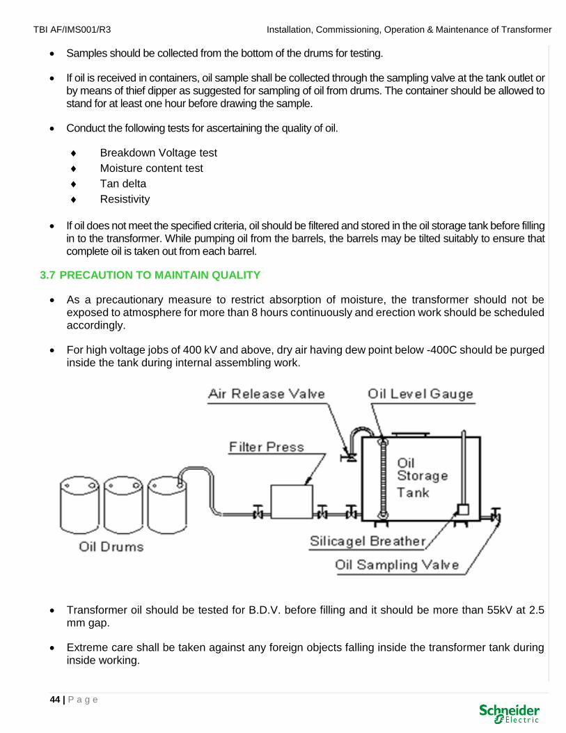
TBI AF/IMS001/R3 Installation, Commissioning, Operation & Maintenance of Transformer
44 | P a g e
• Samples should be collected from the bottom of the drums for testing.
• If oil is received in containers, oil sample shall be collected through the sampling valve at the tank outlet or by means of thief dipper as suggested for sampling of oil from drums. The container should be allowed to stand for at least one hour before drawing the sample.
• Conduct the following tests for ascertaining the quality of oil.
Breakdown Voltage test
Moisture content test
Tan delta
Resistivity
• If oil does not meet the specified criteria, oil should be filtered and stored in the oil storage tank before filling in to the transformer. While pumping oil from the barrels, the barrels may be tilted suitably to ensure that complete oil is taken out from each barrel.
3.7 PRECAUTION TO MAINTAIN QUALITY
• As a precautionary measure to restrict absorption of moisture, the transformer should not be exposed to atmosphere for more than 8 hours continuously and erection work should be scheduled accordingly.
• For high voltage jobs of 400 kV and above, dry air having dew point below -400C should be purged inside the tank during internal assembling work.
• Transformer oil should be tested for B.D.V. before filling and it should be more than 55kV at 2.5 mm gap.
• Extreme care shall be taken against any foreign objects falling inside the transformer tank during inside working.

TBI AF/IMS001/R3 Installation, Commissioning, Operation & Maintenance of Transformer
45 | P a g e
• Keep only one man hole open at a time and close it as soon as possible. Avoid inside working on rainy days.
• Earthwork near the transformer should be avoided when internal assembly is in progress to avoid ingress of dust.
• Any tools taken inside should be tied by string or cotton tape to the person who is using the same. All tools shall be counted and recorded before and after each days work in order to ensure that no tools are left inside.
• Gaskets used are of synthetic rubber bonded cork material. These are to be compressed to 50 ~ 60% of its original thickness. Over tightening and under tightening of gaskets should be avoided as these may cause oil leakage and shortening of gasket life.
3.8 ERECTION OF COOLER BANK
• Generally for oil forced cooled transformers radiators will be mounted in a separate cooler bank.
• Cooler headers supporting ‘A’ frame are mounted on separate foundations. Refer "FOUNDATION DRAWING" for details.
• Since cooler headers are provided with butter fly type shut off valve, oil from main body need not be drained for assembling cooler.
• Cooler Assembly should be carried out referring to "GENERAL ARRANGEMENT" and "PART MARKING DRAWING" of the transformer.
• Check and ensure that level of all the foundations for cooler support are in same level as that of the top surface of rails. Level difference should be compensated by putting shims if the level is lower and chipping the concrete foundation if the level is higher.
• Fix cooler header mounting frames as per dimensions shown in General arrangement and Foundation Plan drawing.
• Mount cooler headers loosely. Final tightening to be done only after proper alignment.
• Top and bottom butterfly valves of all radiators should be in the vertical line. This should be confirmed by a plumb.
• Tighten the cooler frame foundation bolt, and clamping bolts of cooler headers and pipe connections.
• While mounting the oil pump and oil flow indicators, care should be taken to ensure the arrows indicating the oil flow direction are towards the transformer tank.
• While mounting radiators care should be taken to ensure that the weight is balanced.
• Ensure that a fresh gasket is used while mounting the radiators.

TBI AF/IMS001/R3 Installation, Commissioning, Operation & Maintenance of Transformer
46 | P a g e
• In case of separately mounted coolers, the oil pipes are provided with expansion joints. Tack welded bars on expansion joints should be removed.
• Fix the fan mounting frames and fans as indicated in the general arrangement drawing.
• Fan & mounting frame shall be connected to the earth grid.
3.9 PRESSURE RELIEF DEVICE
• Mount PRD as per manufacturers leaflet and also the G.A. drawing of Transformer.
• Check operation of alarm/trip contacts.

TBI AF/IMS001/R3 Installation, Commissioning, Operation & Maintenance of Transformer
47 | P a g e
SECTION-4
FITTINGS & ACCESSORIES

TBI AF/IMS001/R3 Installation, Commissioning, Operation & Maintenance of Transformer
48 | P a g e
4. FITTINGS & ACCESSORIES
4.1 RATING & TERMINAL MARKING PLATE (R & D Plate)
• The transformer is supplied with rating and terminal marking plate made out of noncorrosive metal. The plate contains information concerning the rating, voltage ratio, weights, oil quantity, vector group etc. The plate also includes unit Serial Number. and year of manufacturing.
4.2 TAP CHANGING ARRANGEMENT
(i) Off-Circuit Switch
• The transformer is normally fitted with an off-circuit tap changing switch to obtain required voltage ratio. It can be hand-operated by a switch handle mounted either on tank cover or on the tank side. The locking device is fitted to the handle to lock in any tap position. The switch mechanism is such that it can be locked only when it is located in its proper position and not in any intermediate position.
• THE TRANSFORMERS MUST BE ISOLATED FROM ALL THE LIVE LINES, BEFORE OPERATING THE SWITCH.
• Operating the switch when transformer is energised, will damage the switch contacts due to severe arcing between the contacts and may damage transformer winding. When the switch handle is provided on the side wall, it is necessary that Switch handle assembly is dismantled before untanking.
(ii) Off-Circuit Ratio Changing links
• Sometimes links are provided inside the transformers tank to obtain required voltage ratio. Links are required to be loosened and fixed in new required position as given in R & D Plate. Links are accessible from the inspection cover.
(iii) On-Load Tap Changer
• The on-load tap changer is an optional fitting. The on-load tap changers are provided with local manual control, local electrical control and remote electrical control. The automatic voltage regulation can also be provided as an optional fitting. The tappings are located on high voltage winding.
4.3 EARTHING TERMINALS
• The core laminations assembly is connected to core clamping fame which is in turn connected to the tank. Two earthing terminals are provided on the transformer tank. The earthing terminals should be connected to the earthing.
4.4 LIFTING LUGS
• Two/Four lifting lugs of adequate capacity are provided on tank sides/top cover to lift fully assembled transformer filled with oil. All lugs are designed for simultaneous use and must be used accordingly. Two/Four lifting lugs are all heavy fittings are also provided with individuals lifting lugs.

TBI AF/IMS001/R3 Installation, Commissioning, Operation & Maintenance of Transformer
49 | P a g e
4.5 VALVES
• Every transformer is provided with drain cum filter valve at bottom of the tank, and filter valve at top of the tank. Valves are fitted with plugs/blanking plates to stop oil coming out.
• Mainly two types of valves are provided.
i) Wheel Valves
ii) Butterfly Valves
• The Wheel Valves are used either with female screw threads or with flanges. These are of gun-metal/cast iron type.
• Generally, one isolating valve also known as shut off valve is provided for transformer up to 2000 KVA between conservator and buchholz relay. The Butterfly type cast-steel valves with the machined flanges are used at points of connection between tank and detachable radiators.
4.6 BUSHINGS
a) Oil Communicating Type
• Transformers windings are connected to the external circuit through terminal bushings. The bushings are installed on the cover or, on side walls of the transformer tank. The lower ends of the bushing protrude into the tank and at both their ends are provided with suitable fasteners to connect the line leads inside the transformers with an external conductor outside it.
• The shape and size of the bushings depend on the voltage class, type of current. Bushings of 1000 Volts are of two-piece construction without arcing horns, whereas all other bushings are of single piece porcelain type. Assembly and dismantling of single piece type bushing is possible without disturbing the active part. For bushings of two-piece constructions, tank cover is required to be removed for necessary access to the inner (lower) end of the bushings. These bushings are not detached at the time of transportation.
b) Condenser Bushings
• Generally, Condenser Bushings are used for 72.5 KV and above. These bushings contain their own oil and are sealed to retain the same. Whenever these bushings are mounted on bushing pockets or raised truncated portions, air vent pipes are provided for carrying away air or gases from these pockets to Buchholz relay during service.
• These bushings are detached from the transformers and despatched separately. They are packed as per manufacturers' instructions. The draw through type lead is coiled and kept temporarily below the bushing blanking plate.
• The equipment required for mounting the bushings are
i) Rope slings
ii) Flexible steel wire approx. 2mm in dia., of suitable length.

TBI AF/IMS001/R3 Installation, Commissioning, Operation & Maintenance of Transformer
50 | P a g e
• Typing procedure for mounting is as follows:
(i) Open the bushing case carefully and check it for transit damage and clean the bushing thoroughly.
(ii) Remove the locating pin. The cable bolt to be used on the unit is brazed to the end of the flexible draw through type lead mentioned above.
(iii) Remove the blanking plate and pass the main lead from the porcelain part. Tie the Flexible Steel wire to the head of the bolt fixed temporarily on the top of the cable bolt to facilitate the threading of the main lead through the bushing tube and at the same time preventing the lead from falling back into the tank.
(iv) Suitably raise the bushing and remove the protective cover at the oil end of the bushing.
(v) Check that Oil Level in the bushing is appearing in the Oil Level indicating glass. In case it is not visible, do not mount that bushing. Also, do not fill the oil at site, as chances of failure of bushing are high in this case.
(vi) During the lowering operation, thread the flexible steel wire through the inside tube of the bushing and pull it. Continue the operation till the bushing rests on its flange pocket. Bolt the two flanges and remove the slings.
(vii) Hold the cable bolt in position, remove the flexible wire and insert the locking pin to hold the cable bolt remove the slings.
(viii) For removing air from the central tube after oil filling, unscrew the terminal cap and press the terminal bolt downward,
(ix) Fix upper and lower arcing horns and adjust the gap setting as per the required Insulation Co-ordination.
4.7 CABLE BOXES
• Cable boxes are designed for receiving and protecting cable ends. Insulating paper is most hygroscopic and all paper insulated cable ends must be protected by suitable insulating compound. These cable boxes are provided with brass wiping glands and are designed with clearances inside the box suitable for compound filling. The cable box in such case must be filled with compound as marked as indicated in the drawing.
• Cable boxes for PVC are XLPE cables are designed with air clearances and hence these boxes are not required to be filled with compound.
• Cable boxes of 3.6 KV and above are provided with detachable gland plates. Earthing terminals are also provided on these cable boxes for earthing the armouring of individual cables.
4.8 BUSDUCT
• Some users prefer connections to load by means of busduct. Busduct is supplied by some other agency. However, we provide suitable flanges around transformers bushings for receiving the busduct.

TBI AF/IMS001/R3 Installation, Commissioning, Operation & Maintenance of Transformer
51 | P a g e
• The level of the busduct flanges from ground/rail level is indicated in the General Arrangement drawings of the transformer. The complete details of busduct flange is furnished by us giving complete dimensional details for the matching flanges, bolt spacing, bushing terminal details, etc.
4.9 MARSHALLING BOX
• The transformer is provided with certain fittings directly mounted on the transformer at various locations. These fittings are having electrical contacts or terminals which are required to be connected to the protection schemes to give alarm/annunciation under abnormal conditions and if further required to disconnect the transformer form mains. To facilitate connections of all such devices to the protective scheme, the cable from all such contacts are wired up to a weather-proof terminal box, this box called marshalling box, is also used for housing Oil Temperature Indication (OTI) and winding Temperature Indicator (WTI).
• The capillaries from OTI & WIT come out from the bottom of the Marshalling box through suitably recessed gland plate thus preventing ingress of dust.
• It has a detachable gland plate with glands through which cables enter and leave. It has a rain shed provided on top to prevent rain falling directly over it. All these provisions make Marshalling Box a Weather-Proof enclosure.
4.10 ERECTION OF HV TURRETS AND BUSHINGS
METHOD OF LIFTING CONDENSER BUSHING FROM PACKING CASE AND MOUNTING ON THE TRANSFORMER AT AN ANGLE

TBI AF/IMS001/R3 Installation, Commissioning, Operation & Maintenance of Transformer
52 | P a g e
• Before starting the erection work of Condenser Bushing, lift the Bushing from its crate and keep it vertical and check the oil level. Confirm that oil level is up to the centre of oil sight window of Bushing.
• If oil is drained from the tank a continuous supply of dry air should be ensured while removing the blanking plates and fixing the bushing turrets and bushings.Dry air shall have a dew point of -40OC or better.
• Total exposure time should not exceed 8 hrs. At the end of each day’s work, blank off all openings and pressurise with dry air.
• If weather is bad (rain, snow or fog) the tank should not be opened unless adequate shelter is provided.
• For details of connections from winding to the bushing please refer to the specific drawing and suppliers catalogue given in the instruction manual.
• Ensure that a fresh gasket is used while mounting the bushing.Ensure that the air release pipe connections are oriented towards the correct directions.
• Bushing shall be mounted in the order of B, A, C or B, C, A.
• While mounting the bushings, ensure that the oil level gauge is oriented away from the transformer.
• While lowering draw lead type condenser bushing the cable shall be held tightly by using strong steel/plastic rope. Remember that dropping of cable can cause injury to the personnel and damage to the transformer.
• Check and ensure that secondary terminal of turret mounted C.T. if any are connected to the proper terminals on the terminal board.
• Check and ensure that secondary leads of C.T's. mounted inside the transformer are connected to the proper terminals in the terminal board.
4.11 TEMPERATURE INDICATORS
• Sensing elements of oil and winding temperature indicators are to be fitted on to the thermometer pockets welded on the top cover of the transformer.
• Before mounting the thermal sensing bulbs, inside of the pocket should be cleaned thoroughly and filled with transformer oil upto a depth of half the pocket.
• Care should be taken not to damage the capillary tubing. Capillary tubes should be clamped properly.
• RTD sensor element and heater coil are fitted on the cover.
• CT leads shall be connected on one side and sensor leads are taken from the other side.
• RTD instruments are mounted on the remote panel in the control room.

TBI AF/IMS001/R3 Installation, Commissioning, Operation & Maintenance of Transformer
53 | P a g e
4.12 OLTC DRIVE MECHANISM
• In case of on load tap changing transformer, the OLTC driving mechanism has to be mounted on the transformer. Please refer to the OLTC instruction manual supplied by the OLTC manufacturer.
• Check for mechanical stops at extreme positions by manually operating with the handle.
• Bring the tap position in DM to the tap position 1.
• Connect 3-phase supply with correct phase sequence.
• Check raise/lower operations. If direction is correct, check electrical end stops at extreme positions.
• Different manufacturers of OLTC adopt different designs for the DM. Some manufacturers adopt dry type gear box for the motor and some manufacturers adopt oil filled gear box. Oil, if required, shall be filled as per the manufacturer's instructions.
• Coupling up of drive mechanism and OLTC bevel gear shall be done only after ensuring that both are at the same tap position. Normally the transformer is despatched from the factory at rated Tap position.
• Operate the DM manually from rated tap to tap no. 1 and then to the other extreme tap position and bring back to rated tap.
• Operate DM electrically. Check and confirm that for each impulse given in both raise and lower directions, diverter switch operation sound is heard before the motor stops. After hearing the sound, the travel of the tap position indicating disc upto the green band shall be equal in both forward and backward crank operation.
• Verify the ratios on all taps using ratio meter or digital voltmeter.
4.13 INSTRUCTIONS REGARDING USAGE OF GASKETS
• Gasket materials used are either Synthetic Rubber Bonded Cork (SRBC) sheet or nitrile rubber.SRBC material conforms to RC-70C of IS : 4253(Part II); thickness used are 6.0 mm and 10.0 mm. Gaskets should be stored in stress free condition and must be protected from moisture, oil and grease.
• Synthetic rubber bonded cork sheets once used should not be used again. Gasket seating surfaces should be smooth and free from scratches, oil, grease, dirt etc.
• Gasket should be properly located before tightening. Gasket joints are designed with 40~50% compression.
• Gasket joints should be tightened evenly with a diametrically opposite sequence.
• Over tightening will cause the gasket material to loose its properties and under tightening maynot prevent oil leakage.

TBI AF/IMS001/R3 Installation, Commissioning, Operation & Maintenance of Transformer
54 | P a g e
4.14 CHECKING LEAK RATE UNDER VACUUM
• Drain oil & create vacuum of 200 torr inside the tank, close the valve between vacuum pump and tank and stop the pump and hold the vacuum. There should be no appreciable loss of vacuum over one minute.
• If there is leak, find out the leak and rectify.
• Start the pump and open the valves and continue till a vacuum of 10 torr is achieved. Close vacuums valve and stop the pump. There should not be an increase of pressure of more than 1 torr over half an hour.
• If the rise in pressure is more, find out leak and rectify.
• If results are satisfactory, restart the vacuum pump open the valves and continue pumping to obtain a vacuum of 1 torr or better and maintain this vacuum for more than 24 hrs. before and during subsequent oil filling operations.
4.15 INSULATION OF CORE AND FRAME TO TANK
• If the internal body earthing lead is brought out through low voltage bushings, the megger values shall be measured using 2 kV megger and the values recorded.
4.16 VACUUM OIL INJECTION
• Oil injection shall be made under full vacuum (1.0 torr or better) for transformers above 66kV. 380 mm Hg or better vacuum is required for transformers rated for 66kV and below. The vacuum shall preferably be measured by using McLeod Vacuum Gauge.
• After draining the oil completely from the transformer, vacuum should be pulled from the oil filling hole on main conservator. If the conservator is fitted with air cell, pressure equalising connection is required to avoid damage to the air cell.
• Before starting vacuum, all bolted connections shall be checked. Radiator valves shall be kept open.
• A transparent vinyl hose shall be connected to the bottom sampling valve for indicating the oil level.
• If explosion vent is provided, the pressure shall be equalised on either side of the diaphragm to avoid damage to the diaphragm.
• Vacuum shall be maintained for 6 hours.
• Oil may be injected through the bottom filter valve until the level reaches 35OC marking on the Magnetic Oil Level Gauge of the conservator.
• Natural rubber hose shall not be used as sulphur in the rubber may react with oil.
• Oil inlet valve shall be closed and after one hour the vacuum shall be broken. Oil level indicating vinyl hose can be removed by closing the bottom sampling valve.
• Vacuum gauges may be detached and breathers assembled in its position.

TBI AF/IMS001/R3 Installation, Commissioning, Operation & Maintenance of Transformer
55 | P a g e
• Pressure equalising connection provided for explosion vent diaphragm and OLTC diverter chamber shall be removed.
4.17 TOUCH UP PAINTING AT SITE
• Any damage to the painting of the transformer and accessories shall be made good after erection work is completed.
• If a welding has been done on the transformer at site, the paint film burnt by the welding shall be removed by wire brush or metal spatula.
• Remove the rust by wire brush and emery paper #80 / #100.
• Wash away the oil, grease, dirt and dust by using suitable solvent and dry it up.
• Polish the surface to be painted by using emery paper #80 / #100 and then clean the surface.
• After cleaning, stir the ready mixed rust resistant primer paint 'Yellow Zinchromate' or 'Red Oxide' primer paint.
• Apply the paint uniformly by using a brush. drying time for the paint is normally 4~5 hours.
• After the first coat of paint is dried up, mix and stir the finish coat paint of existing shade and apply by brush uniformly. Drying time of finish coat paint is normally 6 hours.
• Inspect the repainted surface and do re-painting if the painting is not uniform and unpainted surface is visible.
4.18 MIXING OF TRANSFORMER OIL
• Some times a need arises at site to top up a transformer with oil of a different make.
• New oil can be mixed with each other irrespective of the source or degree of refinement if both the oils meet the same standard specification.
• Inhibited oils can be mixed only if the inhibitor used is same in either oils or the other one is uninhibited.
• At any point of time, the percentage of new oil topped up shall be limited to 10% of the total oil quantity.
4.19 INSULATION DRY OUT AT SITE
i) HOT OIL CIRCULATION
• Connect bottom filter valve of tank to inlet point of filter machine. Connect top filter valve of tank to outlet of vacuum filter machine and start oil circulation.
• The filter outlet temperature should be limited to 60 ~ 70°C.
• Continue filtration for 4 cycles.

TBI AF/IMS001/R3 Installation, Commissioning, Operation & Maintenance of Transformer
56 | P a g e
• Oil circuit should include a vacuum chamber in which oil drawn from the transformer is sprayed and the moisture and gases are released from the oil are extracted by the vacuum pump.
• A minimum capacity of 6000 litres per hour is recommended for the circulation equipment.
• Cooler connection at inlet shall be kept closed to minimise loss of temperature during circulation. Outlet valve shall be kept open to allow expansion of oil inside the cooler.
• Drain the oil by simultaneously admitting dry air or nitrogen gas from the top. This is to avoid winding insulation coming in contact with moisture.
• Apply vacuum of 1.0 torr or better and maintain for 6 Hrs.
• Inject oil under vacuum upto a level of approximately half of the conservator.
• Start hot oil circulation again as explained earlier and continue for 4 cycles. Maintain temperature of 60 ~ 70°C.
• Drain oil by feeding dry air or nitrogen gas as explained.
• Apply vacuum as explained. Repeat vacuum/hot oil circulation cycle till required dryness is obtained.
• Normally 3 or 4 cycles of hot oil circulation and evacuation will be sufficient to obtain the required dryness for the insulation.
Variation of Insulation Resistance with Temperature
• Dryness of insulation is determined by measuring insulation resistance of transformer winding.
• Insulation resistance between each pair of windings and also between windings and earth shall be measured by using a 2.5/ 5 kV megger (as per voltage class of winding).
• Readings shall be comparable with the factory test results.
• Direct heating of transformer is not recommended for dry out at site.
• Oil samples shall be tested for moisture content, (Below 20/15/10 ppm for 132/220/400 kV class respectively). Break down voltage (More than 60 kV at 2.5 mm gap). Resistivity ( 1012 ohm meter)
before final oil filling.
• Do not measure insulation resistance when the transformer is in under vacuum or without oil.

TBI AF/IMS001/R3 Installation, Commissioning, Operation & Maintenance of Transformer
57 | P a g e
ii) TRANSFORMER OIL PUMP
• The pump set is a single stage axial flow gland-less type, integral with the drive motor. It has been specifically designed for forced circulation of oil through the cooling system of large transformer & allows thermo-phonic flow.
• It is designed for flange mounting directly to the pipe circuit of transformers in either horizontal or vertical position.
• All the moving parts are completely enclosed and gasket thus permitting open air installation, without any need for protective cover. It is compact in design.
• The Nameplate gives details of pump and motor output along with respective connecting pipe size.

TBI AF/IMS001/R3 Installation, Commissioning, Operation & Maintenance of Transformer
58 | P a g e
SECTION-5
COMMISSIONING

TBI AF/IMS001/R3 Installation, Commissioning, Operation & Maintenance of Transformer
59 | P a g e
5. COMMISSIONING
5.1 INSPECTION AND MAINTENANCE LOG SHEET
• It is important that an inspection and maintenance log sheet be kept regularly. The original of this log sheet should be kept along with the Instruction Manual for future reference and record.
• The log should include dates and details of all inspections and maintenance carried out.
• Results of oil tests and insulation resistance together with the temperatures at the time of measurement should also be recorded in the log sheet.
• Before commencing the test it should be ensured that the secondary terminals of all current transformers are kept short-circuited. After test these shorting connections shall be removed.
5.2 PHYSICAL CHECKS
• Check oil levels in the level gauges of all condenser bushings.
• All air release plugs shall be loosened and closed after releasing trapped air if any.
• Check and confirm tightness of all fasteners.
• Check and confirm that valves are either open or closed as indicated the valve schedule plate.
• Check all bolted gasket joints and confirm that there is no oil leak.
• All blanking plates and spares including spare gasket should be stored carefully for future use.
• Check all cable terminations and ensure that cables are properly connected and cable numbering ferrules are provided.
• Check and ensure that all protective covers like valve guards, LV bushing protection covers etc. are removed.
• Check and confirm that all bushing porcelain are cleaned thoroughly and are without damage.
• Check & confirm that the test tap caps of all Condenser type Bushings are tightened.
• Remove the cap provided at the bottom of silicagel breather for the transportation purpose.
• Arcing horns if provided are set to the specified gap
• All earthing connections are tightened properly.
• Anti condensation heaters are functioning correctly.
• Rating and connection diagram plates and other marking labels are fitted properly.
• All isolating switches are set at ON position.
• Cooler control switch is set to AUTO.
TBI AF/IMS001/R3 Installation, Commissioning, Operation & Maintenance of Transformer
60 | P a g e
• All alarm circuits are reset.
• OLTC to Transformer equalising pipe shall be removed after oil filling under vacuum and the opening shall be coverd by blanking plate supplied with the transformer.
5.3 INSULATION RESISTANCE CHECK
• Check and record insulation resistance between pair of windings and windings to earth using 2.5/ 5 kV Motorised megger and record the values at 15, 60 & 600 seconds. (Refer Appendix-C)
• Calculate the ratios of insulation resistances IR 600/ IR 60 (Polarisation Index.) and IR 60/ IR 15. Compare the values with factory test results.
• Check insulation resistance between core and frame to ground if the earthing connection is brought out through bushings.
5.4 RATIO TESTS
• Connect 3-phase 415 volts supply between HV terminals and measure the voltage ratios at all taps and record. (Refer Appendix-C)
• Earth connections from star point shall be removed during measurement and reconnected after tests.
5.5 VECTOR GROUP TESTS
• Connect 415 V, 3-phase supply to HV winding terminals. The transformer shall be at rated tap.
• Connect one HV terminal to one LV terminal and measure voltage between each HV terminal to each LV terminal in turn. Compare the values with factory test results. (Refer Appendix-C)
5.6 MAGNETIC BALANCE TEST
• Single-phase 240 volts is applied across any HV/LV winding (wrt voltage class) and voltage induced across the other phases are measured and record (Refer Appendix-C) and compared with the factory test results.
CAUTION: If there is a residual magnetism in the core, it can give erratic readings.
5.7 SHORT CIRCUIT IMPEDENCE
• LV terminals are shorted by using suitable cables.
• 3 phase 415 volts supply is connected to HV winding and HV exciting current of all the phases and LV circulating currents of all the phases are measured and recorded.
• Percentage impedance = Rated current x Applied voltage x 100 Measured current x Rated voltage
• Compare the results with factory test results.

TBI AF/IMS001/R3 Installation, Commissioning, Operation & Maintenance of Transformer
61 | P a g e
5.8 WINDING RESISTANCE MEASUREMENT
• Note down the oil/winding temperature. If the measurements are done after hot oil circulation; the oil/winding temperature may be different from the ambient temperature.
• Measure the resistance of all windings using a Micro-Ohm meter.
• Convert the resistances to 75°C.
R (75) = R (measured) x (234.5 + 75) (234.5+Oil temperature at the time of measurement)
• Compare the values with factory test results.
5.9 OPERATION CHECKS
• Check direction of rotation of pumps and fans.
• Check and confirm that flow indicators are mounted correctly.
• Check signalling circuits for pump fail/fans fail etc., and reset.
• Check setting of over load relays and reset.
• Tripping arrangement shall be connected for below mentioned accessories before transformer
charging: - WTI
OTI
PRV (Main Tank)
PRV(OLTC)
BUCHHOLZ Relay
MOLG
Low Oil Level Tripping
5.10 BUCHHOLZ RELAY OPERATION
• Check inclination of Buchholz relay pipe. The slope should be in upward direction, between 3 ~ 9O to horizontal towards the conservator.
• Connect a compressed air line (Pressure 4 kg/cm2) or a nitrogen cylinder to the petcock on top of the Buchholz relay. Open the petcock slowly and allow air to enter into the Buchholz relay.
• Check the continuity of alarm contacts by using a multimeter. Record the volume of air in the Buchholz Relay at which the alarm switch contact closes.
• Close the air supply and release all the air by opening the other petcock on the Buchholz relay. Open the petcock quickly and allow air full flow with surge. Record the minimum pressure required to operate the surge contacts.
• Release all the air trapped in the Buchholz relay.

TBI AF/IMS001/R3 Installation, Commissioning, Operation & Maintenance of Transformer
62 | P a g e
SECTION-6
TRANSFORMER ACCESSORIES

TBI AF/IMS001/R3 Installation, Commissioning, Operation & Maintenance of Transformer
63 | P a g e
6. TRANSFORMER ACCESSORIES
6.1 TEMPERATURE INDICATOR
i) INSTALLATION AND MAINTENANCE INSTRUCTIONS
APPLICATION
• The Temperature indicator is used as an Oil Temperature Indicator (OTI) or as Winding Temperature Indicator (WTI) for the protection of liquid immersed power transformer. In the case of dry type transformers, it is used as Temperature Indicator (T.I.) to monitor the temperature of the windings.
ii) SCOPE OF SUPPLY
• OTI & WTI: Instrument with specified Range, Number of control switches, length of capillary and sensing bulb.
• TRANSMITTER (OPTIONAL): A precision potentiometer is mounted inside the case of OTI or WTI to transmit the measured temperature to remote point(s).
• REPEATER (OPTIONAL): Analogue indicator supplied separately for remote indication of the temperature measured by OTI or WTI.

TBI AF/IMS001/R3 Installation, Commissioning, Operation & Maintenance of Transformer
64 | P a g e
iii) OPERATION
• The instrument operates as OTI when its sensing bulb is mounted in an oil filled pocket located in the hottest oil of an oil immersed transformer.
• The instrument operates as WTI when its sensing bulb is exposed to the medium adjacent to the windings of a dry type transformer.
• When a proportionate load current of the transformer is passed through the thermal image device, the instrument operates as a WTI integrating the simulated temperature rise of the thermal image device and the top oil temperature measured by the sensing bulb.
• Remote indication of the temperature measured by the OTI or WTI is provided by connecting the transmitter to the repeater either directly or through a resistance transducer (resistance to current converter).
iv) CONSTRUCTION
• LIQUID-FILLED SYSTEM: A sensing bulb, a measuring bellows and a small-bore capillary tube connecting the two, form the measuring system.
• A second bellows connected with a second capillary running parallel to the first capillary and terminated at the head of the bulb from the temperature compensating system. Both the systems are completely filled with the same liquid.
• The two bellows are linked to a compensating lever in such a manner that the effect of ambient temperature changes on the capillary line and measuring bellows is compensated.
• The movement of the measuring bellows is related only to the temperature being measured by the sensing bulb.
• This movement is amplified by the link and lever mechanism, which directly drives the rotating disc carrying the control switches. The same mechanism moves, through rack and pinion a separately mounted indicating pointer over a calibrated dial.
• Head compensation is provided by sealing both the systems under initial pressure, which is greater than the possible head pressure due to differences in the elevation between the bulb and indicator.
v) MAXIMUM POINTER (RED COLOURED): Located on the indicator lid, is resettable from outside the case by a screw driver blade. Unscrew and remove black cap to reach the screw driver-slot.
CAUTION: Never use the switch testing knob for setting the maximum pointer. If used, the switch contacts will close and initiate the external control circuits when the instrument is in operation.
vi) SWITCH TESTING KNOB: It is fitted on the indicator lid to check mercury switches setting and potentiometer operation. These knobs when rotated moves the indicating pointer, switch mechanism and potentiometer wiper together and facilitates testing these circuits without opening the lid. Rotate the knob slowly and steadily for an accurate check. Never allow the knob to spring back suddenly or quickly, as this will cause damage.

TBI AF/IMS001/R3 Installation, Commissioning, Operation & Maintenance of Transformer
65 | P a g e
vii) THERMAL IMAGE DEVICE: A heater coil is fitted around the measuring bellow and supplied from a current transformer in the load circuit of transformer. The heater coil simulates hot-spot temperature of the winding over top oil temperature for a given load. The measuring bellows reacts to this simulated temperature rise in addition to the top oil temperature measured by the sensing bulb and the instrument functions as a WTI displaying the hottest spot temperature of the winding. An adjustable shunt resistor (17-calibrating shunt) is provided for shunting portion of the current through the heater coil to obtain precise thermal image.
viii) ELECTRICAL CONNECTION: All internal electrical connection is wired to the terminal block mounted inside the indicator case. A wiring diagram is fixed inside the case of each indicator. Switches are identified by markings S1, S2, S3 and S4 on them. Terminal Nos. wired to each circuit are detailed below.
ix) GRADIENT ADJUSTMENT: After opening the instrument lid, carefully remove the dial. Withdraw the calibrating shunt after removing the nut and retaining washer. One adjustable centre band and two fixed bands at the ends are provided in the shunt. One supply lead is connected to the centre band and the other lead to the lower band on the shunt. Slacken the screw in the retaining clip of the centre band. To reduce the temperature rise, move the centre band nearer to the lower band, to increase the temperature rise reverse the procedure. Retighten the screw on the centre band after adjustment. Replace the shunt, dial and lid. Repeat the calibration, check after adjustments until the accuracy limits achieved.
x) INSTALLATION MOUNTING: Mount the instrument in a vertical position. Otherwise errors, particularly in the horizontal plane, will upset the zero setting of the mercury switches. Place a sprit level on the top of the indicator case to ensure correct positioning and operation of the mercury switches. If vibration exists at the mounting position, mount the indicator on a non-vibrating structure. Suitable anti-vibration mountings are supplied. Do not use these mountings during transport.
xi) CAPILLARY LINE: Do not stretch hard twist or bend the capillary to a radius less than 75 mm. Continuously support the capillary by suitable clips at intervals of 300 to 450 mm. Allow necessary slack at the bulb and for mounting and removing the bulb without sharp bend at the joint. Wind in spiral (minimum dia. 150 mm) the possible excess length of capillary close to the indicator or the bulb.

TBI AF/IMS001/R3 Installation, Commissioning, Operation & Maintenance of Transformer
66 | P a g e
6.2 GAS OPERATED (BUCHHOLZ) RELAYS
i) PREFACE
• One of the most essential devices to protect a transformer is a Buchholz relay. For more than 20 years, Buchholz relays have been manufactured in India. They are made by an experienced staff of skilled workers, highly qualified technicians and engineers ensuring a high degree of precision and quality.
ii) GENERAL
• Power Transformers are considered to be a highly reliable type of equipment, yet, in order to ensure the continuity of service that modern conditions demand, protective devices are required. The purpose of such devices is to disconnect faulty apparatus before large-scale damage is caused by’ fault to the apparatus or to other connected apparatus. Such devices generally respond to a change in the current or pressure arising from the faults and are used for either signalling or tripping the circuits.

TBI AF/IMS001/R3 Installation, Commissioning, Operation & Maintenance of Transformer
67 | P a g e
• Protective devices in the ideal case must be sensitive to all faults, simple in operation, robust for service and economically feasible. Considering liquid immersed transformers, a near-ideal 'protective device' is available in the form of Gas and Oil relay described here. This gas is collected in the body of the relay and is used in some way or other to close the alarm or the tripping circuit
• The principle of the Gas and Oil relay was first successfully demonstrated and utilised by 'Buchholz' many years back.
iii) APPLICATIONS
• Double element relays can be used in detecting minor faults in a transformer. The alarm element will operate, after a specified volume of gas has collected to give an alarm indication. Examples of incipient faults are –
i) Broken-down core bolt insulation
ii) Shorted laminations
iii) Bad contacts
iv) Overheating of part of windings.
• The alarm element will also operate in the event of oil leakage, or if air gets into the oil system.
• The trip element will be operated by an oil surge in the event of more serious fault such as - i) Earth faults
ii) Winding short circuits
iii) Puncture of bushings
iv) Short circuit between phases
• The trip element will also be operated if a rapid loss of oil occurs. Single element relays can be used to detect either incipient or major faults in oil filled potential transformers, reactors, capacitors etc. A special single element relay is available for the protection of on load tap-change equipment.
iv) SWITCH DATA
Type : Normally Open
Contact Rating : 250 V A.C. (r.m.s.) or D.C. max.
Switching Current : 5 A - A.C. or D.C. max.
Switching Voltage : 300 V D.C. max---240 Volts A.C. (r.m.s.) max.
Breakdown voltage : 650 Volts D.C. min.
Initial Contact Resistance : 70 milli-ohms max.
Resonant Frequency : Greater than 700 Hz.
Actuating Time : 2 milli-seconds (Typical)

TBI AF/IMS001/R3 Installation, Commissioning, Operation & Maintenance of Transformer
68 | P a g e
v) ARRANGEMENT OF TERMINALS AND MEANS OF PROTECTION FOR REED SWITCH CONTACT
6.3 OIP CONDENSER TYPE BUSHINGS
• These instructions are crucial for the proper handling, installation, operation & maintenance of Oil Impregnated Paper Condenser Bushings and these should be in the possession of those who are responsible for the above activities.
INSTRUCTIONS FOR INSTALLATION, OPERATION AND MAINTENANCE OF OIP CONDENSER BUSHINGS
i) DESIGN AND CONSTRUCTION
• The general constructional details of the bushing, intended for oil-air application are shown in Fig. 1. The active part of the bushing consists of an Oil Impregnated Paper (OIP) core (1) manufactured from superior grade Kraft insulating paper with condenser graded layers for field control, wound under tension on central tube / conductor (2).
• The innermost condenser layer is electrically connected to the central tube / conductor (2) and the outermost layer is electrically connected to the fixing flange (3) through a test tap (11). The core is dried under heat and vacuum and then impregnated with superior grade of insulating oil.
• Porcelain insulators (4 & 5) on the upper and lower sides of the bushing, oil resistant high-quality rubber gaskets & ‘O’ rings (6) are held together with the central tube by means of a set of powerful springs (7).
• The fixing flange (3) is provided with a test tap (11) for the measurement of Capacitance and Tan delta, air releasing screw (10) to release the air trapped in the transformer during topping up of oil or can be connected to Buchholz relay, name plate giving the product details, handle / eyebolt for lifting and space for ring type CT's on the oil end of the bushing.
• At the oil end, an epoxy coated stress shield or base plate (15) is provided to control the high stresses in oil inside the transformer. A detachable bottom arc shield is provided for bushing rated 245 kV and above. The intervening space between the core and the porcelain insulators is filled with specially treated mineral oil under vacuum.

TBI AF/IMS001/R3 Installation, Commissioning, Operation & Maintenance of Transformer
69 | P a g e
• A Prismatic (up to 300kV) or magnetic (up to 400 kV) Oil sight glass (14) is provided on the expansion bowl (8). A top terminal (12) is provided to connect to the overhead line.
• Arcing horns (16, 17) are provided on request. (Ref. Fig. 3). Test Tap: - (Refer Fig. 2)
• The test tap (11) is provided for the measurement of Capacitance, Tan delta and Insulation Resistance (IR) values of the bushing. It is connected with a copper lead to the last condenser foil of the core directly. During normal service this test tap is electrically connected to the mounting flange through test tap cover. The threaded test tap cover must be fixed properly (Fig 2a) before putting into service.
ii) PACKING AND STORAGE
• To prevent physical damage to the bushings, generally only one bushing is packed in wooden packing case. At times, more than one bushing is also packed in the case of bushings of lower voltage rating. The bushing is placed in the packing case at an angle of 6-8 degrees to horizontal. Accessories like arcing horns, terminals etc. are also packed in the same packing case.
• This is to ensure the core remains immersed in oil. When the packed bushings are stored outdoors, they should be kept horizontal and covered with tarpaulin for protection from rain and other atmospheric contaminants.
• Measure the IR values of the bushing with a 2.5 kV megger.
The recommended values are:

TBI AF/IMS001/R3 Installation, Commissioning, Operation & Maintenance of Transformer
70 | P a g e
4000 Meg ohms (Min) between oil end terminal or top and test tap.
1500 Meg ohms (Min) between test tap and flange with 1 kV meggar.
• The IR values may vary due to the atmospheric condition (humidity), surface cleanliness of the porcelains, dryness of test tap etc. In such cases, preheating of porcelains, terminals test tap etc., with hot air is recommended.
• However, the healthiness of the bushings can be known only after measurement of Tan delta & capacitance values.
• Capacitance and Tan delta values of the bushing should be measured between the top terminal and test tap at 2 kV to 10 kV (Maximum). The measurement should be preferably carried out indoors with RH not exceeding 60% and at ambient temperature, with the facilities and procedure as described as described below:
Schering Bridge
Standard loss free capacitor
High Voltage Supply
Neccesary screened connecting leads

TBI AF/IMS001/R3 Installation, Commissioning, Operation & Maintenance of Transformer
71 | P a g e

TBI AF/IMS001/R3 Installation, Commissioning, Operation & Maintenance of Transformer
72 | P a g e

TBI AF/IMS001/R3 Installation, Commissioning, Operation & Maintenance of Transformer
73 | P a g e
• Place the bushing vertically on suitable stand. Remove the threaded test tap cover. Insert a plug / clip into the central stud of the test tap and connect to the Schering Bridge through a screened cable. The flange body should be grounded. Connect the high voltage supply to the top terminal. Measure the capacitance & tan delta value of bushing up to a maximum of 10 kV.
Note: The voltage applied on the bushing should be limited to 10 kV, when the bottom end is not immersed in oil. Utmost care should be taken to avoid any contact with the bushing during testing as this may result in fatal injury to the personnel.
• The test tap should be dry, free from any moisture condensation and dirt deposition. The threaded test tap cover should be fixed back to the test tap, immediately after the test.
• Factory test values of tan delta and capacitance are indicated in the test report of individual bushing at working voltages. However, site values may vary, as they do not resemble factory test conditions.
• The site values recorded at the time of commissioning should be taken as the reference values for comparison with future measurements. The bushing can be commissioned, if tan delta value measured is less than or equal to 0.007, and capacitance value as per the factory test value with maximum variation of 10%. If higher values are obtained, please contact ALSTOM, Customer Service Department giving full details of testing arrangement, for further advice.
Note: The bushing should be kept vertical or mounted on transformer for a minimum period of 24 hours before application of voltage.
iii) INSTALLATION: (Please refer to Fig.8)
• The bushing is suitable for installation for a maximum angle of 30 degrees from vertical. During the lowering of the bushing into the transformer, extreme care should be taken to prevent the lower porcelain hitting the wall of the tank. The bushing should be so mounted on the transformer that the oil sight glass is visible from the ground level. Ensure the visibility of the oil level to the naked eye.
• Maximum stress experienced by the bushing is at the bottom stress shield during testing. Hence sufficient care should be taken to avoid any flashover from the stress shield to the wall of the turret. The flashover voltage depends on the clearance maintained in oil between the stress shield and turret, oil quality, surface smoothness, presence of barriers, shape of the stress shield and turret etc. The recommended size of the turret to be maintained for various voltage class of bushings is given in the manufacturer’s booklet / respective drawings.
iv) BUSHING WITH DRAW LEAD CONNECTION: (Please refer to Fig.9)
• Each bushing is supplied with a top terminal (12), cable bolt (9), cable bolt pin and a gasket placed separately in the packing case.
• Drills a hole of suitable diameter based on the size of the flexible transformer cable at the bottom end of the cable bolt and braze the cable into it. Insert an M8 bolt at the upper end of the cable bolt and tie a wire or a fish cord on to it. Clean the gasket seating surface on top face of the transformer and place the gasket in position. Lift the bushing above the transformer turret and clean the bottom end of the bushing.

TBI AF/IMS001/R3 Installation, Commissioning, Operation & Maintenance of Transformer
74 | P a g e
• Lower the bushing slowly into the transformer; simultaneously pull the transformer cable brazed with cable bolt through the central tube with the help of the fish cord. Secure the cable bolt to the central tube with the cable bolt pin. Remove the fish cord. Bolt the bushing into position taking care to correctly position the gasket joint. Tighten the terminal to the cable bolt ensuring full thread engagement for proper current transfer.
• Sometimes the cable bolt is supplied along with the brazed flexible lead up to the flange seat with a half connector at bottom end. In such cases the flexible lead from the transformer winding should be brazed to the other half connector and should be fastened with the draw lead connector of the bushing using bolts and nuts.
v) BUSHING WITH DRAW-ROD CONNECTIONS: (Please refer to Fig. 10)
• Bushings of higher current ratings are provided with draw rod type arrangement with a half overlap bolted joint at the flange seat.
• Remove the draw rod through the bushing tube or take it out from the packing case. Clean the outer surface and braze the transformer cable to the lower half connector. Clamp the upper and lower half connectors together with bolts and nuts. Follow the installation instructions as described for draw lead type of bushing.
vi) BUSHING WITH SOLID STEM (Please refer to Fig. 11)
• In solid stem type of bushings, the central conductor forms the current carrying part. Mount the bushing on the turret and connections should be made to the top and bottom terminals individually. The transformer cable termination should be connected to the bottom terminal with bolts & nuts, through the viewing port of the transformer. The top terminal should be fixed directly to the central conductor.
vii) CHECKS AFTER INSTALLATION
• After installation, clean the bushing thoroughly with a dry cloth and carry out physical inspection for any damage on the porcelain / leakage that might have occurred during installation.
• Check the oil level of the bushing.
• Ensure the top terminal is fixed tightly with the gasket provided to avoid entry of moisture in to the transformer.
• Measure and record the capacitance and tan delta values of the bushing. Here again the values may differ from the previous ones.
• Measure magnetizing current during Site Acceptance Test (SAT).
Note: The threaded test tap cover should be fixed back to the test tap immediately after the test.The bushing should be kept vertical mounted on the transformer for a minimum of 24 hours before energisation.
CAUTION: THE TEST TAP WILL ALWAYS BE EARTHED AS LONG AS THE THREADED CAP IS FIXED. HENCE THE CAP SHOULD NEVER BE KEPT OPEN.

TBI AF/IMS001/R3 Installation, Commissioning, Operation & Maintenance of Transformer
75 | P a g e
viii) PERIODICAL CHECKS AND MAINTENANCE
• As the bushing is a self-contained unit, as such there is no specific maintenance to be carried out. However, a periodical check of the oil level and cleaning of the porcelain will normally suffice.
• In order to determine the healthiness of the bushing, measurement of capacitance and tan delta may be carried out during annual maintenance. These values are to be compared with the pre-commissioning test results. Tan delta value more than 0.007 and increase in capacitance by more than 10% or more, if observed, should immediately informed to AREVA for further advice.
ix) SAFETY
• Understanding the procedures and instructions are a must while handling bushings. Also, all applicable safety procedures such as regional or local safety rules and regulations must be followed. Safe working practices and good judgement are essential by the personnel while installing, testing, maintaining or disposing the bushings.
6.4 SILICA GEL BREATHER
SILICAGEL DEHYDRATING BREATHER FOR TRANSFORMER
• A dehydrating breather is used to dry the air that enters a transformer as the volume of oil decreases because of fall in temperature.
• Air entering the breather is first drawn through an oil seal and passes upwards through the silica gel crystals to the connecting pipe at the top. During this upward passage of air, any moisture present is absorbed by the dry silica gel.
• The oil seal ensures that the gel absorbs moisture only when the transformer is breathing.

TBI AF/IMS001/R3 Installation, Commissioning, Operation & Maintenance of Transformer
76 | P a g e
i) INSTALLATION
The breather is usually detached from the tank and shipped separately; the silica gel charge is filled in from the top and blanked with a plug. To install, it is necessary to:
1) Remove plug by unscrewing cap nut.
2) Remove the plug.
3) Assemble the pipeline from conservator to breather mounting.
4) Fill the oil cup with transformer oil to the indicated level. This is very important to prevent the
dust and moisture inside conservator.
ii) MAINTENANCE
• Inspect the breather on monthly basis; more frequently, if found necessary by experience (e.g. highly humid atmosphere).
• When the breather is first installed, the crystals have a blue tint, and after a period of operation, the colour of the tinted crystals gradually changes to pink; this is an indication that the silica gel is becoming saturated and losing its absorbent properties. When there is a preponderance of pink crystals the gel should be changed or reactivated.
• Silica gel may be reactivated by heating in a shallow pan at a temperature of 150° C to 200° C for two to three hours when the crystals should have regained their original blue tint.
• Before filling the container with silica gel, clean and dry all parts of the breather. Verify that the oil Level in the oil cup is correct when reassembling.
• Ensure that the breather is not choked and is free for passage of air.

TBI AF/IMS001/R3 Installation, Commissioning, Operation & Maintenance of Transformer
77 | P a g e
6.5 MAGNETIC OIL LEVEL GAUGE: (MOLG)

TBI AF/IMS001/R3 Installation, Commissioning, Operation & Maintenance of Transformer
78 | P a g e
OIL LEVEL INDICATOR
• MODEL SO-03
• MODEL SO-06
• MODEL SO-10
i) APPLICATION
This model of indicator is manufactured considering Transformer application. It can also be used as Content Gauge on other tanks where level of liquid inside the tank is required to be indicated continuously on a dial.
ii) CONSTRUCTION, WORKING & FEATURES
• A float is used as sensor of liquid level inside the conservator (tank). Swing of hinged float due to change in liquid level is utilised to indicate level on a calibrated dial and to operate a switch for external alarm unit.
• Use of magnetic coupling in the indicator achieves complete sealing off of liquid inside the conservator from surrounding atmosphere. This result in avoiding any leakage of costly oil and avoiding contamination of insulating oil due to seepage of surrounding air in the conservator.
• The glass mercury switch is nylon encapsulated to avoid breakage and spilling of mercury. Switch is accessible for servicing while indicator is mounted on the conservator without any necessity of draining the oil.

TBI AF/IMS001/R3 Installation, Commissioning, Operation & Maintenance of Transformer
79 | P a g e
iii) CALIBRATION
The standard calibration of dial is Empty, 1/4, 1/2, 3/4, Full. Calibration of marks Empty & Full is done after leaving 65 mm from bottom and top of conservator to avoid striking of float to conservator wall. Different calibrations are done to suit customer's needs.
iv) MOUNTING
In fig. 2, indicator is shown mounted by keeping dial and mounting pad in vertical position. However, indicator can be mounted in titled position towards ground (max 30°) for easy viewing by fixing mounting pad at desired angle. The position of indicator on the conservator can be selected to suit site condition. Float mechanism passes through the hole in pad.
v) ALARM SWITCH & CONNECTIONS
One mercury switch is provided for Low Level Alarm. The Normally Open switch closes when oil level drops to 10 mm above Empty level i.e. 75 mm from bottom of conservator. Leads from mercury switch are brought into a terminal box positioned at the bottom of indicator (see Fig. 4B), A two-way terminal strip is provided which is accessible for connection after removing cover of terminal box. A hole with 3/4” B.S.P. is provided for cable gland. Wiring should be done as per Fig. 4B.
vi) SPECIFICATIONS
Operating Liquid : Transformer Oil to IS: 335
Working Temperature : 0 to 100° C of Oil
Working Pressure : 0 to 4 kg/cm²
Environment : For Indoor & Outdoor use
Weight : 6.6 Kg. with Float & Float-arm
Float Travel : Float moves in right angle plane to seating face (See Fig.2)
Electrical witch : One SPST Mercury Switch
Contact Rating : 5 Amp 240 V.AC. 50 Hz., 1.2 Amp. 240 V DC. Switch Setting : Normally Open Closes when oil level drops to Empty level.
Switch opens automatically when oil level rises.
Dial Size : 250 mm dia.
Dial Position : Vertical or Inclined
Conservator diameter : Available for use in range of 600 to 1500 mm dia.

TBI AF/IMS001/R3 Installation, Commissioning, Operation & Maintenance of Transformer
80 | P a g e
6.6 PRESSURE RELIEF VALVE
• MODEL: - T-3
• MODEL: - T-5
• MODEL: - T-6
i) APPLICATION
This PRV is designed to be used on Power Transformer. When pressure in the tank rises above predetermined safe limit this valve operates and performs following functions.
• Allows the pressure to drop by instantaneously opening a port of about 150 mm diameter.
• Gives visual indication of valve operation by rising a flag.
• Operates a micro switch.
This switch has 1 NO and 1 NC contacts (Four terminals). Hence switch can be effectively used in control circuit.
ii) CONSTRUCTION & WORKING
• This PRV has an integral flange with six holes for mounting. The valve can be mounted vertically or horizontally on the tank. The PRV has got a port of about 150 mm dia. This port is sealed by a stainless-steel diaphragm.

TBI AF/IMS001/R3 Installation, Commissioning, Operation & Maintenance of Transformer
81 | P a g e
• The diaphragm rests on an 'O' ring and is kept pressed by two heavy-duty springs, thereby keeping the port closed. The other side of the diaphragm is exposed to tank pressure. Whenever the pressure in the tank rises due to any reason, the same pressure acts on the diaphragm from inside. When pressure rises above predetermined safe limit the diaphragm gets lifted from its seat.
• This lifting is instantaneous and allows vapours, gases or liquid to come out of tank depending upon the position of valve on tank.
• The diaphragm restores its position as soon as pressure in the tank drops below set limit. The lift of the diaphragm is utilised to operate flag and micro switch with the help of rod. The flag and switch remain operated until they are reset manually.
iii) CHECK FOR VALVE
• Remove the cover of switch box. By lifting the operating rod check operations of switch as stated in Test 4 in test certificate with the help of an AVO meter. After checking, reset the switch by pressing knob. Replace the cover.
• The flag operation should be checked manually by lifting the rod. Reset the flag by turning it down. Handling of flag should be done very carefully.
• The product label indicates the suitability of valve for synthetic liquid or for transformer oil. A proper valve should be selected. Normally Red product label is used for synthetic liquid and Black label for transformer oil.
• A Gasket for base is supplied with each valve.
iv) FAULTS AND REMEDIES
• The valve has rugged construction and it is not likely to get damaged easily. However, the indicating flag is delicate item. Hence if is likely to get damage.
• The indicating flag can be replaced by either making similar flag at your end or by asking for replacement.
• You can repair with the help of good instrument mechanic as minor faults can occur during working of switch or flag mechanisms.

TBI AF/IMS001/R3 Installation, Commissioning, Operation & Maintenance of Transformer
82 | P a g e
6.7 COOLING FANS
i) GENERAL
Exhaust type cooling fans used on transformers are designed to operate outdoors in all weather conditions. Generally, the following sizes of fans are used.
The fans are designed to operate outdoors in all weather conditions.
ii) MOTORS
The fans are powered by totally enclosed, squirrel cage induction motors. The motors are adequately rated to give reliable service for many years.
iii) IMPELLER
• The impeller is designed to give maximum volume at minimum noise level with minimum power consumption.
• For reducing vibrations, special shoes made of rubber are provided at fixing points of fan lugs.
iv) MOUNTING
Size Speed Input Voltage Frequency Current
(mm) (r.p.m.) (watts) (volts) (Hz) (Amp)
1 610 700 240 3 415 50 0.5
2 610 900 500 3 415 50 0.9
Sr. No. Phase

TBI AF/IMS001/R3 Installation, Commissioning, Operation & Maintenance of Transformer
83 | P a g e
• The arm is secured by the resilient mounting caps, which are placed over the rubber sockets and secured to the diaphragm with 8 screws, nuts and washers provided. The lock washers should be fitted under the heads of the screws.
• Rubber sockets fitted to arms. To be fitted so that flat side will come in contact with the diaphragm.
• NOTE: Lock washers are supplied and should be fitted.
• Setscrew in blade should engage in dimple nearest the end of the shaft. After blade is fitted, see that split pin 5 is replaced in end of shaft.
6.8 FLEXIBLE SEPARATOR (AIR CELL)
i) INTRODUCTION
• Flexible separator (Air Cell) is provided inside the conservator of power transformers for avoiding direct contact of air with the transformer oil. Air Cell provides a permanent, flexible and non-porous barrier between the atmosphere and the transformer oil without affecting the operational function of the system.
• The basic construction of the separator is a highly resistant fabric coated externally to resist transformer oil and internally to Ozone and weather resistant.
• Flexible separators offer the following advantages :-
Avoids contact between air and oil and consequently of condensation or oxidation inside the transformer.
Protection against water vapour and gases.
Suppression of any gas bubble formation in oil.
Compensation of large volume changes.
ii) DESCRIPTION

TBI AF/IMS001/R3 Installation, Commissioning, Operation & Maintenance of Transformer
84 | P a g e
• Flexible separator is fitted inside a cylindrical conservator. Oil being outside, the separator is in direct contact with atmosphere. This type of mounting makes it possible to compensate for the oil volume displacements due to temperature variations.
iii) CHARACTERISTICS OF MATERIAL
• Flexible separators are made from coated fabric consisting of: Textile reinforcement i.e. highly resistant polyamide fabric.
• External coating chemically resistant to transformer oil.
• Inner coating resistant to Ozone and all weather conditions.
• Major characteristics of materials are listed below:
Mass — 1400 ± 140 g/m²
Coating — Poly acrylonitrile butadiene
Textile reinforcement — Polyamide
Breaking Strength before immersion in oil — > 300 daN/5cm.
iv) INSTALLATION PROCEDURE
Mounting of Air Cell and Oil Level Gauge in Conservator
1) Connection to the inside of Air Cell
2) Connection to the inside of Conservator
3) Details of Hook on Conservator and Handle on Air Cell
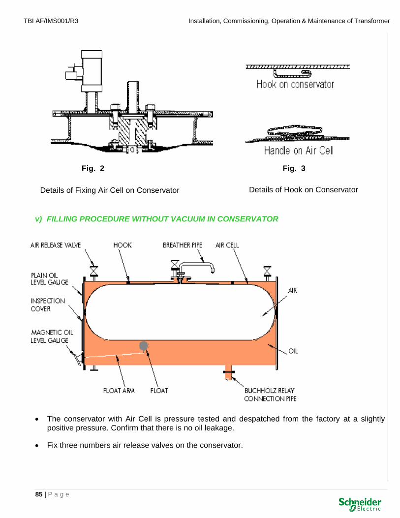
TBI AF/IMS001/R3 Installation, Commissioning, Operation & Maintenance of Transformer
85 | P a g e
Fig. 2 Fig. 3
v) FILLING PROCEDURE WITHOUT VACUUM IN CONSERVATOR
• The conservator with Air Cell is pressure tested and despatched from the factory at a slightly positive pressure. Confirm that there is no oil leakage.
• Fix three numbers air release valves on the conservator.
Details of Fixing Air Cell on Conservator Details of Hook on Conservator

TBI AF/IMS001/R3 Installation, Commissioning, Operation & Maintenance of Transformer
86 | P a g e
• Keep air release valves open. Fix air filling adapter on breather pipe and inflate the air cell at an air pressure indicated on the INSTRUCTION PLATE affixed on the transformer and hold air pressure.
DO NOT APPLY EXCESS AIR PRESSURE AS IT MAY DAMAGE THE AIR CELL
• Open air release valves and start oil filling from the bottom of the conservator.
• Observe the air release valves and as soon as oil starts overflowing, close the air release valves one by one. Stop oil filling when all air release valves are closed.
• Remove the air filling adapter.
• Continue oil filling and observe the Magnetic Oil Level Gauge (MOLG)
• Stop the filling when the needle of MOLG shows the level corresponding to the ambient temperature at the time of filling.
• Fix silica gel breather.
vi) FILLING PROCEDURE UNDER VACUUM IN CONSERVATOR
• The conservator, with its separator, being set up and plugged in above the transformer, is connected to its oil filling reserve by a pipe in its lower part.
Proceed as follows:
➢ Create a vacuum in separator.
➢ With the same source of vacuum, create a vacuum in the conservator.
➢ Open the oil filling valve of the transformer.Because of the vacuum in the conservator, the oil level rises automatically.
➢ Stop the oil filling once the required volume in the conservator is attained.
➢ While maintaining the conservator under vacuum, allow Dry Air or Nitrogen gas to enter into the internal part of the separator. Then, the separator inflates by itself, and takes all the free space due to the fact that the conservator was not completely full. In particular, during the operation, the oil is going to rise to the top of the conservator.
➢ Inflate the separator at a maximum as shown in the INSTRUCTION PLATE.
➢ Check on the vent-holes, and confirm that there is no more air in the conservator or, if necessary, adjust the level.
vii) EXPLOSION VENT
• The diaphragm fitted at the exposed end and inner of the vent should be inspected at frequent intervals and replaced if damaged. Whenever lower diaphragm of double diaphragm explosion

TBI AF/IMS001/R3 Installation, Commissioning, Operation & Maintenance of Transformer
87 | P a g e
vent ruptures, oil rises inside the explosion vent pipe and is visible in the level indicator on explosion vent.
• Failure to replace the outer diaphragm quickly will allow ingress of moisture which will contaminate the oil. If diaphragm is broken because of fault in the transformer, an inspection should be carried out to determine the nature and cause of the fault.
CARE AND MAINTENANCE OF DIAPHRAGM
• The diaphragm fitted at top end of explosion vent, must be inspected for any sign of damage before the transformer is commissioned.
• If diaphragm is found damaged it must be replaced immediately to avoid oil contamination with moisture.
• When the explosion vent is fitted with an air released plug of pet cock, it is recommended to keep it open while filling oil is conservator and must be closed after oil filling operation is completed.
6.9 OIL TO WATER HEAT EXCHANGER
i) INTRODUCTION
• In transformer oil cooler, the hot oil from the transformer is passed through the shell, which comes in contact with the external surface of the tubes, which is constantly cooled by the incoming cooling water flowing inside the tubes.
• Heat transfer takes place due to temperature difference between the oil and cooling water flowing through tubes resulting in cooling of the oil.
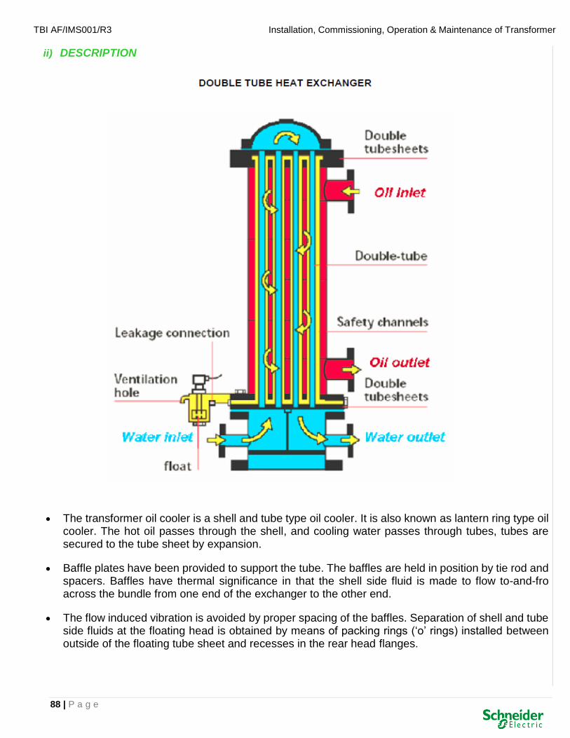
TBI AF/IMS001/R3 Installation, Commissioning, Operation & Maintenance of Transformer
88 | P a g e
ii) DESCRIPTION
• The transformer oil cooler is a shell and tube type oil cooler. It is also known as lantern ring type oil cooler. The hot oil passes through the shell, and cooling water passes through tubes, tubes are secured to the tube sheet by expansion.
• Baffle plates have been provided to support the tube. The baffles are held in position by tie rod and spacers. Baffles have thermal significance in that the shell side fluid is made to flow to-and-fro across the bundle from one end of the exchanger to the other end.
• The flow induced vibration is avoided by proper spacing of the baffles. Separation of shell and tube side fluids at the floating head is obtained by means of packing rings (‘o’ rings) installed between outside of the floating tube sheet and recesses in the rear head flanges.

TBI AF/IMS001/R3 Installation, Commissioning, Operation & Maintenance of Transformer
89 | P a g e
• The shell and tube fluids have their own packing rings (‘o’ rings), which are separated, by a lantern ring provided with weep holes for leak detection. Leakage at the packing will not cause mixing of the shell side and tube side fluids within the exchanger itself.
• Channel side has been provided with pass partition arrangement so as to have the flow of cooling water inside the tubes in each section. The inside surface of channel except tube sheet have been coated with epoxy paint to prevent corrosion of carbon steel material. Zinc anodes are provided to reduce the galvanic corrosion.
iii) HYDRO TESTING
• The equipment shall be subjected to hot oil test on shell side and hydro test on tube side to a pressure of 1½ times of the design pressure to check for leaks.
• Before conducting hydraulic test for new unit or one that has been out of service for some time or for unit that has been opened, carry out a thorough internal and external inspection to ensure:
• All foreign materials have been removed
• Pressure gauges have been correctly calibrated
• Vent on high point of unit (air vent) if installed is left open
iv) OPERATING INSTRUCTIONS
Inspect the transformer oil cooler and ensure that the external surfaces and channels are free of dirt and ensure the readiness of cooling water supply on the tube sides.
v) START UP PROCEDURE
The startup of the oil cooler in a system consists of putting into service various equipment in a definite logical operating sequence.
Open the vent and drain valve on the channel side of the oil cooler.
Establish cooling waterflow through channel and tubes.
When water flows through the vent and drain close the same.
Open the oil side vent & drain and adopt the same procedure as that of tube side
Temperature of oil shall be raised gradually with specified flow rate.
vi) PERFORMANCE OF THE OIL COOLER
• Use proper strainers on shell side and tube side.
• Do not operate the cooler beyond the specified working pressure indicated in the nameplate.
• Operate the cooler at the specified flow rate to obtain maximum efficiency.
• The oil should not have any contamination as the performance of cooler get reduced.

TBI AF/IMS001/R3 Installation, Commissioning, Operation & Maintenance of Transformer
90 | P a g e
• Periodic cleaning of the cooler on shell side and tube side shall be carried out for better performance.
vii) SHUT DOWN PROCEDURE
• The oil flow should be completely stopped before stopping the water flow.
viii) CLEANING METHODS
• The bundle assembly is taken out and the internal and external surface of the tubes are cleaned by smooth wire mesh or cleaning agent.
• After cleaning, the bundle is inserted and the gasket and ‘o’ ring is replaced with new ones and the equipment is tested hydraulically before setting the unit under operation.
ix) PRESERVATION
• When the transformer oil cooler is out of service, preservation by proper methods are essential to prevent corrosion.
• It is recommended that during short duration of operational interruptions as a preventive measure against stand still corrosion, a continuous flow of cooling water through tubes is to be maintained. If this is not possible then it is necessary to clean the tubes to remove dirt, impurities etc. And fill with suitable clean water to retain in same condition.
• In case of longer shut down, the shell side of the oil cooler is to be drained and rinsed with oil. Dry all internal surfaces of oil cooler by using hot air. Blank all open nozzles to avoid ingress of dust. Clean the tube side to remove dirt, impurities etc., and fill with suitable clean water and retain in that condition.
TYPES OF PRESERVATION PROCESS
a) WET PRESERVATION
• The wet preservation is used in case of short term shutdowns. In case of wet preservation of plants/systems or components, it is to be observed that the filling water is mixed with sufficient quantity of suitable corrosion inhibitors.
• The preservative fluid should be circulated once in a week and analyzed periodically.
• The consumed chemicals are to be substituted.
b) DRY PRESERVATION
• The dry preservation is used in case of long term shut downs. In case dry preservation, it is important that the plants/systems or components are completely dried before passing nitrogen or dry air.
• The preservative air, which is to be blown through plants/systems or components to be maintained dry, shall be dust free, oil free and free from aggressive ingredients. The relative humidity of the out coming preservative air should be less than 20% with reference to 20°C.

TBI AF/IMS001/R3 Installation, Commissioning, Operation & Maintenance of Transformer
91 | P a g e
• The effectiveness of the measure taken is to be checked at regular intervals.
P.S.: The above instructions are applicable for single tube Heat Exchangers.
6.10 BCD TPI
• The potential free (NO) contacts coming from the BCD Encoder are connected to the respective terminals A1 (LSB), A2, A3, A4, A5, A6 (MSB), along with the common as marked on the Rear Panel of the TPIB.
• When the (NO) contacts close, the logic level is considered as ‘HIGH’ & vice versa. When the unit is powered on, the TPI display indicates the current position of the Tap-changer. Check the TPI by changing the tap positions (BCD code) from 1 (min) to 33 (max) and confirm that TPI reads correctly.
• When all the inputs are open the TPI display indicates zero. For any other input other than the BCD input for Taps 1 to 33 the TPI displays “Er”.
6.11 DGPT2 / DMCR RELAY
DGPT2 : Detection of Gas Pressure and Temperature DMCR : Detection, Measurement and Control Relay

TBI AF/IMS001/R3 Installation, Commissioning, Operation & Maintenance of Transformer
92 | P a g e
• Fitted directly to the transformer cover, DGPT2 relay ensures protection against internal faults, prolonged overvoltages and fire risks associated with the use of inflammable dielectric fluids.
• The DMCR Protection Relay is the most complete safety solution for a transformer. It protects your transformer by monitoring temperature, pressure, oil level and gas accumulation inside the tank.
• The oil level monitoring function of the DMCR relay allows the tripping of the transformer (or setting off of an alarm, depending on the user set up) if the level of oil is decreasing abnormally or if there is gas accumulating inside the transformer.
• In the event of gas accumulation, it can be sampled through the bleeder and then analyzed.
• Temperature monitoring is done via a probe located inside the thermowell immersed in transformer oil. There are two monitoring levels: an alarm level and a tripping level.
• Both levels can be set freely. Temperature is constantly displayed on the relay thermometer.
• Pressure monitoring is done through a pressure switch. This pressure switch is located in the upper part of the DMCR relay and it monitors pressure inside the tank on a 0.1 bar to 0.5 bar scale.
• The tripping threshold of the pressure switch can be set freely. However, it is factory-set at time of order on a speciallyengineered test bench, which is a guarantee for precision.
6.12 On-line DGA
• On-line DGA has advanced to a point where full, 9 gas analysis can now be performed many times a day according to a pre-programmed schedule, without any user intervention required. Providing unprecedented levels of information, these devices add a whole new dimension to the field of fault detection.
• By adding communication to the monitoring units, users can remotely track daily, weekly and seasonal gassing trends. These essentially real-time results can be used, not only to detect active faults but even to predict the development of a fault before it becomes a real service issue.

TBI AF/IMS001/R3 Installation, Commissioning, Operation & Maintenance of Transformer
93 | P a g e
• On-line DGA monitoring devices were based on simple versions of laboratory Gas Chromatography (GC) equipment, packaged in a way so as to allow them to work in a field environment.
6.13 AVR RELAY (AUTOMATIC VOLTAGE REGULATING RELAY)
• Automatic Voltage Regulating Relay (AVR) is used to Regulate the secondary voltage of Power and Distribution Transformers via On-Load Tap Changer (OLTC).
• AVR relay comes with following features :
Digital readout for PT Supply and Deadband settings
LED indication for Raise, Lower presignals and UV and control Relay operations
Continuously adjustable Time delay settings
Automatic resetting after Voltage correction
Single pulse operation of Control Relays
Undervoltage internal blocking

TBI AF/IMS001/R3 Installation, Commissioning, Operation & Maintenance of Transformer
94 | P a g e
6.14 A-EBERLE RELAY
• Both simple and demanding measurement, control and regulation tasks can be carried out using the new RegSys™ voltage-control system.
• The REG-D™ voltage regulator (basic device), PAN-D and PAN-A1/A2 voltage monitoring units as well as interface modules with binary inputs and outputs and analogue inputs and outputs are used as an optimal solution for these varied tasks.
• Every REG-D™ regulator can be used as a regulator and at the same time as a transformer monitor, measurement transducer, recorder, statistical unit and ParaGramer.
• All important network measurement quantities are displayed in measurement transducer mode. Changes in the regulated voltage and additional selectable measurement quantities are recorded in recorder mode.
• The statistical unit for the tap-changer position offers a clear display of all switching operations of the tap-changer. The ParaGramer provides a complete busbar simulation. It is particularly useful for the parallel connection of several transformers.

TBI AF/IMS001/R3 Installation, Commissioning, Operation & Maintenance of Transformer
95 | P a g e
SECTION-7
OPERATION & MAINTENANCE

TBI AF/IMS001/R3 Installation, Commissioning, Operation & Maintenance of Transformer
96 | P a g e
7. OPERATION & MAINTENANCE
• After the inspection and pre-commissioning tests are successfully completed the transformer can be energised at no load.
• Oil soaking/ settling duration of 48 hours for transformers up to 245 kV class and 72 hours for 400 kV and above class are recommended after completion of hot oil circulation and before energising.
• Excessive vibration if any on any part of the transformer shall be located and rectified.
• Transformer shall be observed for any abnormality.
• If any gas is collected inside the Buchholz relay, it shall be analysed for its combustibility. If gas is not combustible, it indicates air trapped inside the transformer.
• All instruments should be checked for any abnormal indication.
• Check winding temperature and oil temperature readings at least once in every shift.
• Check and confirm that tap position indicators is same in local and remote indicators.
• Check and confirm that none of the alarms are indicated.
• Ensure that cooler power supply isolator is ON.
• Ensure that cooler control is in AUTO.
• Ensure that pumps and fans are running smoothly as temperature dictates. If the temperature is below the ON setting neither the pump nor fan should be running.
• After watching the operation of the transformer at no load for 24 hours and confirming that everything is normal, the transformer shall be taken on load.
• Observe the rise in temperature of oil and winding temperature indicators.
• While temperature is rising, confirm that fans and pumps are switched on automatically at the pre-set temperatures.
• While temperature is falling, observe that the pumps and fans are switched off at pre-set temperature.

TBI AF/IMS001/R3 Installation, Commissioning, Operation & Maintenance of Transformer
97 | P a g e
7.1 PERIODIC INSPECTION SCHEDULE FOR POWER TRANSFORMER
Sr. No. Items to be inspected Frequency
1 Load current Hourly
2 Terminal Voltage Hourly
3 Ambient Temperature Daily
4 Winding Temperature Daily
5 Oil Temperature Daily
6 Tap position Daily
7 Air cell conservator Daily
8 Oil level in Conservator Daily
9 Oil level in Bushings Daily
10 Oil level in OLTC Conservator Daily
11 Oil level in breather cup Daily
12 Number of On-load Tap changer operations (Refer On-load tap changer manual)
Monthly
13 External connections (Earthing, Cables etc.) Monthly
14 Dust deposits & physical damages to bushings Monthly
15 Air passage & colour of silica gel in breather Quarterly
16 Cable boxes, Gasket joints, gauges etc. Quarterly
17 Dielectric strength of transformer oil Quarterly
18 Moisture content of transformer oil Quarterly
19 Dissolved gas analysis of transformer oil Half yearly
20 Insulation resistance of windings Half yearly
21 Tightness of gasketed joints & Oil leakages Half yearly
22 Tan delta & Capacitance of condenser bushings Yearly
23 Operation of relays and their circuit Yearly
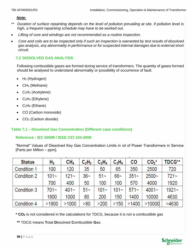
TBI AF/IMS001/R3 Installation, Commissioning, Operation & Maintenance of Transformer
98 | P a g e
Note:
** Duration of surface repainting depends on the level of pollution prevailing at site. If pollution level is high, a frequent repainting schedule may have to be worked out.
• Lifting of core and windings are not recommended as a routine inspection.
• Core and coils are to be inspected only if such an inspection is warranted by test results of dissolved gas analysis, any abnormality in performance or for suspected internal damages due to external short circuit.
7.2 DISSOLVED GAS ANALYSIS
Following combustible gases are formed during service of transformers. The quantity of gases formed should be analysed to understand abnormality or possibility of occurrence of fault.
• H2 (Hydrogen)
• CH4 (Methane)
• C2H2 (Acetylene)
• C2H4 (Ethylene)
• C2H6 (Ethane)
• CO (Carbon monoxide)
• CO2 (Carbon dioxide)
Table 7.1 – Dissolved Gas Concentration (Different case conditions)
Reference : IEC 60599 / IEEE C57.104-2008
“Normal" Values of Dissolved Key Gas Concentration Limits in oil of Power Transformers in Service [Parts per Million – ppm].
* CO2 is not considered in the calculations for TDCG, because it is not a combustible gas
** TDCG means Total Dissolved Combustible Gas.

TBI AF/IMS001/R3 Installation, Commissioning, Operation & Maintenance of Transformer
99 | P a g e
Condition - 1
Total Dissolved Combustible Gas (TDCG) and any individual combustible gas below this level indicate normal operation of the transformer. If any gas exceeds the specified level, it needs investigation.
Condition - 2
TDCG and any individual combustible gas in this range indicate greater than normal combustible gas level. A fault may be present. Further monitoring is required.
Refer Table 7.2 for recommended sampling frequency and actions
Condition - 3
TDCG and any individual combustible gas in this range indicate a high level of decomposition of cellulose insulation and / or oil.
Refer Table 7.2 for recommended sampling frequency and actions
Condition - 4
TDCG and any individual combustible gas in this range indicate excessive decomposition of cellulose insulation and / or oil. Continued operation could result in failure of the transformer.
Refer Table 7.2 for recommended sampling frequency and actions
Note: A sudden increase in key gases and the rate of gas generation are more important in evaluating a transformer than the amount of gas.

TBI AF/IMS001/R3 Installation, Commissioning, Operation & Maintenance of Transformer
100 | P a g e
Table 7.2 – Action based on TDCG
Note:
Either the HIGHEST CONDITION BASED on the INDIVIDUAL GAS or TDCG can determine the condition (1,2,3 and 4) Example If the TDCG is 1941 ppm this indicate condition 3. However Hydrogen is greater than 1800 ppm , The transformer condition 4.
Determine Load Dependence Means if possible find out if the gas generation rate in ppm goes up or down. Perhaps the transformer is unloaded. Take sample every time load change, if load changes are too frequent this may not be possible.
Sampling
IntervalOperating Procedures
Exercise caution.
Analyze for individual gases.
Determine load
dependence.
10 to 30 Quarterly
<10 Annual
>30 Monthly Exercise caution.
10 to 30 Monthly Analyze for individual gases.
<10 QuarterlyDetermine load
dependence.
>30 Weekly Exercise extreme caution.
10 to 30 Weekly Analyze for individual gases.
Plan outage.
Advise manufacturer.
>30 DailyConsider removal from
service.
10 to 30 Daily Advise manufacturer.
Exercise extreme caution.
Analyze for individual gases.
Plan outage.
Advise manufacturer.
Sampling intervals and operating
procedures for gas generation ratesConditions
TDCG levels
(μL/L)
TDCG rate
(μL/L/day)
Condition 1
Continue normal operation.
Condition 2
Condition 3
Condition 4
Monthly>30
≤720
721 to 1920
1921 to 4630
Monthly<10
Weekly<10
>4630

TBI AF/IMS001/R3 Installation, Commissioning, Operation & Maintenance of Transformer
101 | P a g e

TBI AF/IMS001/R3 Installation, Commissioning, Operation & Maintenance of Transformer
102 | P a g e
Dissolved Gas Analysis using Key-gas Ratios
(Ref. CIGRE Report 15.01.01: October 1999)
Key ratio No. 1: (INDICATION: DISCHARGE)
C2H2 (acetylene /ethane): >1 indicates fault C2H6
Key ratio No. 2: (INDICATION: PARTIAL DISCHARGE)
H2 (hydrogen /methane): >10 indicates problem CH4
Key ratio No. 3: (INDICATION: THERMAL FAULT)
C2H4 (ethylene /ethane): >1 indicates thermal fault C2H6
Key ratio No. 4: (INDICATION: CELLULOSE DEGRADATION)
CO2 (carbon dioxide /carbon monoxide): >10 indicates thermal
CO over heating: >3 indicates electrical fault
Key ratio No. 5: (INDICATION: INTANK TAPCHANGER)
C2H2 (acetylene /hydrogen): >2 & C2H2 >30 ppm indicates possibility H2 of tap changer oil leaking into main tank
Note: Ratios are to be calculated only if the concentrations of both the gases are above the detection levels.
7.3 OIL SAMPLING
• Oil sample should be tested for the following and results recorded: -
(i) ELECTRIC STRENGTH
• If the dielectric strength of oil in transformer is less than 55 kV at 2.5 mm gap, the oil must be filtered to improve the characteristics.
• For line end OLTC diverter chamber, oil filtration is recommended when the BDV is 40 kV at 2.5 mm gap.
• For neutral end OLTC diverter chamber, oil filtration is recommended when the BDV is less than 30 kV at 2.5 mm gap.
(II) MOISTURE CONTENT
• For transformers of 400 kV and above class, if the moisture content is found to have increased beyond 20 ppm oil should be filtered.
• For transformers of voltage class up to 245 kV, if the moisture content is found to have increased beyond 25 ppm oil should be filtered.

TBI AF/IMS001/R3 Installation, Commissioning, Operation & Maintenance of Transformer
103 | P a g e
(III) ACIDITY
• If It the acidity is increased beyond 0.5 mg KOH/g, then the oil needs filtration.
• After draining the oil completely from the transformer, core, winding, insulation and interior of tank should be washed by hot oil jet. The oil being used for washing of internal body also must be drained completely.
• Refilling of oil in transformer should be done under vacuum.
(IV) SAMPLING PROCEDURE
• Special care in oil sampling is required for Delta connected transformer and autotransformers.
A. TOOLS REQUIRED
• Spanner sets
• Thermometer
• Steel sampling bottles with polyethylene cone caps.
• Silicon rubber tubing 10 mm bore - 1 m long.
• Clean synthetic sponge.
• Polyethylene sheet - 1 m square
• Clean cloths
• Self-adhesive labels
B. PROCEDURE
• The sampling bottles shall be labelled and marked with information like source of sample, date and time & sample temperature.
• Sample bottle shall not be opened before it is needed for testing.
• Sampling point should be cleaned by using sponge.
• Blanking plate of sampling valve shall be removed by using spanner.
• Clean the silicon rubber tubing thoroughly and fit to sampling point nipple.
• Rinse the bottle in oil stream and reduce the rate of oil flow to 1 litre/minute.
• Put the end of rubber tubing to sampling bottle and fill the bottle from bottom.
• No air bubble shall be introduced into the bottle.

TBI AF/IMS001/R3 Installation, Commissioning, Operation & Maintenance of Transformer
104 | P a g e
• The bottle is allowed to overflow before it is closed.
• Measure and record the temperature of oil sample as soon as it is taken.
• Put back and tighten the blanking plate.
• Remove all tools, excess oil container and oil sample from the area.
• Arrange for testing oil sample at laboratory.
7.4 WINDING TEMPERATURE INDICATOR TESTS
(i) TOOLS AND MATERIALS
• Hot oil bath (with heating facility)
• Secondary injection test set
• Multi-meter
• Clinical thermometer
• Keys of marshalling box.
(ii) PROCEDURES
• The purpose of this check is to confirm that the winding temperatures Indicators are functioning accurately.
• The transformer shall be isolated and earthed.
• Rotate the indicator pointers slowly to the alarm set value and confirm from the control room that the alarm signal has been received.
• Rotate the pointer still further and confirm from the control room that trip signal is received.
(iii) CALIBRATION
• Remove the thermal sensing bulbs from the transformer and insert it into the hot oil bath.
• Check the winding temperature readings up and down the scale at intervals of 5 °C.
• Confirm from control room that remote temperature readings are tallying with the local readings.
• Replace the sensing element into the transformer pocket.
For any adjustment, see the manufacturer's catalogue.

TBI AF/IMS001/R3 Installation, Commissioning, Operation & Maintenance of Transformer
105 | P a g e
(iv) SECONDARY INJECTION TESTS
1) ONAN RATING
• Set the cooler supply isolator of OFF position.
• Connect the secondary injection test set across the heater coil terminals.
• Inject current and check the resultant gradient for ONAN rating.
2) OFAF RATING
• In order to carry out these tests the pump must be running.
• Set the cooler isolator to ON position.
• Set the cooler switch to fans and pumps.
• Check and confirm that the pump is running.
• Inject current in the heater coil and check the gradient for OFAF rating.
• Disconnect.
• Set the cooler control switch to AUTO.
7.5 BUCHHOLZ RELAY FUNCTIONAL TEST
(i) TOOLS AND MATERIALS
• Multi-meter
• Nitrogen cylinder with regulator and pressure gauge or air supply (4 kg/cm²)
• Bucket
• 10 mm polythene tube, 10 meters.
(ii) PROCEDURE
• The purpose of this test is to ensure correct operation of Buchholz relay.
• Transformer shall be isolated and earthed.
• Connect nitrogen cylinder to the top petcock of Buchholz relay.
• Open the other petcock.
• Allow gas to enter the relay.
• Check and confirm from control room that alarm signal is received.

TBI AF/IMS001/R3 Installation, Commissioning, Operation & Maintenance of Transformer
106 | P a g e
• Check continuity of alarm contact by using multi-meter.
• Close petcock on gas supply side and release all gases trapped in relay casing.
• Increase the gas pressure to approx. 2 kg/cm² (30 psi)
• Open the test petcock and allow full surge of gas to enter the relay casing.
• Check and confirm from control room that trip signal has been received.
• Check continuity of trip contacts by using multi-meter.
• Close Buchholz relay test cocks.
• If relay has not operated, increase gas pressure and repeat the test.
• If the relay is observed to be faculty replace it with a new one.
• Open conservator shut off valve and release all gases trapped.
7.6 TAP CHANGER OPERATION
• Regular inspection of tap changing equipment is not required because mechanical operation of tap changer does not involve significant contact wear.
• It is sufficient to operate the tap changer through the whole range of tap selector positions twice a year.
• The purpose of this check is to ensure correct mechanical operation of tap changer.
• Transformer shall be isolated and earthed.
• Note the tap position.
• Operate the tap changer through operating handle through entire range of tap positions.
• Return to the original tap position.
• Set the local selector switch to LOCAL.
• Press RAISE button and release. Check and confirm the tap position indication has changed and that limit switch stops the tap changing at pre-set tap and repeat the process.
• Press the LOWER button and release. Check and confirm that limit switch has operated and tap position indication has changed.
• Repeat till the tap position has returned to the original value.
• Set the local selector switch to REMOTE.

TBI AF/IMS001/R3 Installation, Commissioning, Operation & Maintenance of Transformer
107 | P a g e
7.7 OIL FILTRATION
• Purpose of this maintenance is to improve the unsatisfactory condition of oil found during sampling.
• Transformer shall be isolated and earthed.
(i) TOOLS AND MATERIALS
• Oil conditioning plant (Filter Machine)
• 50 mm flexible hoses of sufficient length for oil inlet and outlet.
• Hose adapters to match the flanges of top and bottom filter valves.
• Cleaning cloths
(ii) PROCEDURE
• Remove the blanking plate from filter valves and connect the oil inlet hose to top filter valve and oil outlet hose to the bottom filter valve.
• Open the filter valves and start circulation of hot oil. Oil temperature shall be 55°C to 70°C.
• Circulate the oil for 4 full passes.
• Re sample and arrange to test.
• Continue until oil condition is acceptable.
(iii) CORRECTIVE MAINTENANCE
• All flange gaskets must be renewed wherever joints are dismantled.
• Cleanliness of gasket surfaces and correct compression (40 % ~ 50% approx.) of gasket must be ensured during reassembling.
7.8 REMOVING AND REFITTING CONSERVATOR & BUCHHOLZ RELAY PIPELINE
(i) TOOLS AND MATERIALS
• Hydra crane or chain pulley block to handle the weight of conservator.
• Oil storage tank/drum as per estimated oil quantity.
• Blanking plates
• Oil filter machine
• Hoses of sufficient length for oil inlet and outlet.
• New gaskets

TBI AF/IMS001/R3 Installation, Commissioning, Operation & Maintenance of Transformer
108 | P a g e
(ii) PROCEDURE
• Transformer is isolated and earthed.
• Close the isolating valves on either side of Buchholz relay
• Disconnect the Buchholz relay control wires.
• Disconnect the MOLG control wires.
• Remove the drain plug of the Buchholz relay and drain oil from the Buchholz relay.
• Remove the conservator oil from conservator drain valve.
• Disconnect the main tank to conservator pipeline (Buchholz relay pipeline).
• Blank the top cover and conservator with the blanking plate.
• Remove the silicagel breather pipe.
• Remove the conservator from main tank.
• For refitting conservator and Buchholz Relay.
• Remove the blanking plate.
• Fix new gaskets.
• Mount the conservator.
• Replace the claming bolts in semi-tightened condition.
• Fix the Buchholz relay and pipeline between conservator to main tank with either side isolating valve.
• Tighten the clamping bolts.
• Connect the Buchholz relay and MOLG control wirings.
• Fix the silicagel breather pipeline.
• Open the isolating valves on either sides.
• Open top air release plug and close when oil starts flowing out.
• Maintain the oil level in conservator (between ½ to ¾).
• Fix the silicagel breather and fill the required oil up to the arrow mark in the oil cup of the silicagel breather.(For transformer without having AIR CELL)
• Procedure for transformer having AIR CELL

TBI AF/IMS001/R3 Installation, Commissioning, Operation & Maintenance of Transformer
109 | P a g e
• Inflate the AIR CELL by injecting N2 /Dry air through Buchholz relay pipe by using AIR CELL chanrging kit and pressure gauge.
• Refer our AIR CELL charging instruction plate mounted on transformer.
• Open the air release plugs top of the either side of the conservator.
• Release the air till oil comes out.
• Close both the air release plugs and clean the oil.
• Check the oil level in POLG in conservator.
• Ensure that oil level in the POLG should indicate the full level.
• Remove the AIR CELL charging kit from the breather pipe.
• Fix the silicagel breather and fill the required oil up to the arrow mark in the oil cup of the silicagel breather.
7.9 REMOVING AND REFITTING RADIATOR
(i) TOOLS AND MATERIALS
• Jib crane to handle the weight of radiator.
• Oil container as per estimated oil quantity.
• Oil drain hose 50 mm bore
• Hose adapter to match flanges of fitter valve.
• Oil filter machine
• New gaskets.
(II) PROCEDURE
• Transformer shall be isolated and earthed.
• Set the cooler supply isolator of OFF.
• Close the inlet and outlet valves if radiator is mounted on a separate cooler tank.
• Close the top and bottom isolating valves of radiator.
• Open the top air release plug.
• Remove the bottom drain plug and drain the oil to oil container under gravity.
• Sling the radiator with jib crane.

TBI AF/IMS001/R3 Installation, Commissioning, Operation & Maintenance of Transformer
110 | P a g e
• Remove the radiator clamping bolts.
• Remove radiator.
• Blank off the radiator and header openings.
• Close the air release and drain plugs.
• For Refitting the Radiator.
• Remove the blanking plates.
• Fix new gaskets.
• Assemble the radiator and tighten the clamping bolts.
• Open the top header air release plug.
• Open the bottom radiator isolating valve.
• If the radiator is on a separate cooler bank, oil shall be filled into the radiator bank through the bottom header valve by using the filter machine. If the radiator is tank mounted, the oil from the oil tank should be pumped into the tank by using the filter machine.
• Close the air release plug on top as soon as oil starts flowing through the air release plug.
• Shut down the oil filter machine
• Open top header isolating valve.
• In case of separate cooler banks, air should be released through the top common header air release plugs.
7.10 REMOVING & REFITTING BUSHINGS
(i) TOOLS AND MATERIALS
• Hydra crane with skilled manpower to handle the weight of the bushing.
• New gaskets.
• Oil filter machine
• Oil storage tank/drum as per estimated oil quantity.
• Blanking plates
• Hoses of sufficient length for oil inlet and outlet.

TBI AF/IMS001/R3 Installation, Commissioning, Operation & Maintenance of Transformer
111 | P a g e
(ii) PROCEDURE
• The transformer is to be isolated and earthed.
• Disconnect the incoming and outgoing cable connnections.
• Drain the oil from the bushing through inlet hose pipe below the top cover of the transformer.
• Unbolt the hadwares between bushing & metal part and bushing & tank.
• Remove the bushing with the help of skilled manpower/sling and Hydra.
• Remove the metal parts and blank the bushing hole.
• For refitting of bushing.
• Fix new gaskets.
• Take out winding terminals from bushing hole (turret).
• Place the bushing with the help of skilled manpower/sling and Hydra.
• Replace and tighten the clamping bolts.
• Tighten the winding terminals to the bushing.
• Fill the oil up to the top level in case of OCP bushing.
(iii) REFITTING FAN AND MOTOR
• Assemble the fan and motor in position and tighten clamping bolts.
• Re connect the power supply wires.
• Unlock marshalling box and set cooler supply isolator to ON.

TBI AF/IMS001/R3 Installation, Commissioning, Operation & Maintenance of Transformer
112 | P a g e

TBI AF/IMS001/R3 Installation, Commissioning, Operation & Maintenance of Transformer
113 | P a g e
SECTION-8
PRODUCT END-OF-LIFE INSTRUCTIONS

TBI AF/IMS001/R3 Installation, Commissioning, Operation & Maintenance of Transformer
114 | P a g e
8. PURPOSE
• The product family must be disposed according to the legislation of the country. This document is intended for use by end of life recyclers or treatment facilities.
• It provides the basic information to assure an appropriate end of life treatment for the components and materials of the product.
Product Range:
ODT (Oil Distribution Transformer) up to and including 5000kVA/33kV
Size: H x L x W in mm (min.) = 1500 x 2200 x 2100 approx.
H x L x W in mm (max.) = 3500 x 5500 x 4500 approx.
Weight: In tonnes= between 1~10
MPT (Medium Power Transformer) above 5000kVA/33kV
Size: H x L x W in mm (min.) = 3000 x 2000 x 3000 approx.
H x L x W in mm (max.) = 7500 x 10000 x 7000 approx.
Weight: In tonnes= between 10~100
Operations recommended for the end of life treatment
• There are several steps to process the products at the end of life so as to recover components, materials or energy:
Reuse → Separation for special treatment → Other dismantling → Shredding
• The components of the products that optimize the recycling performances are listed, identified and located hereunder.

TBI AF/IMS001/R3 Installation, Commissioning, Operation & Maintenance of Transformer
115 | P a g e
b
b
b
b
c
c
c
c
b
b
b
b
e
e
e
e
d
d
d
d
(3)
(3)
(3)
(3)
b
b
b
b
a
a
a
a
(1)
(1)
(1)
(1)
(2)
(2)
(2)
(2)
OD
T (O
il Dis
tributio
n T
ransfo
rmer)
up
to a
nd
inclu
din
g 5
00
0k
VA
/33
kV
MP
T (
Me
diu
m P
ow
er
Tra
ns
form
er)
ab
ove 5
000kV
A/3
3kV

TBI AF/IMS001/R3 Installation, Commissioning, Operation & Maintenance of Transformer
116 | P a g e
For ODT (Medium Power Transformer)
For MPT (Oil Distribution Transformer)
• Mineral oil (a) is the most impacting component on environmental pollution and end of life process should be managed carefully. Long duration skin contact and breathing should be avoided. During draining process, necessary precautions must be taken to prevent oil leaking to the ambient and drained oil must be preserved in appropriate containers.
• Conductor (e) may contain paper insulation material which can be harmful to the environmental because of its mineral oil absorption. This paper insulation should be managed as un-recyclable material as similar as mineral oil. During dismantling of conductors, same attention than oil draining must be paid and long duration skin contact and breathing should also be avoided.

TBI AF/IMS001/R3 Installation, Commissioning, Operation & Maintenance of Transformer
117 | P a g e
Sr.#
Pro
duct
s
End
of l
ife
(Life
cyc
le)
of p
rodu
ct
(In
year
s)
Ven
dor
Nam
e
Haz
ardo
us
subs
tanc
e re
late
d
to e
nvir
onm
ent
Env
iron
men
tal
impa
ct d
urin
g
Tra
nspo
rtat
ion
Env
iron
men
tal i
mpa
ct d
urin
g O
pera
tion
End
of l
ife tr
eatm
ent
Dis
posi
tion
met
hod
1
Dis
trib
utio
n an
d
Pow
er
Tran
sfor
mer
oil
fille
d
(The
envi
ronm
enta
l
anal
ysis
was
perf
orm
ed in
conf
orm
ity w
ith
ISO
140
40)
25 Y
ears
Schn
eide
r
Ele
ctric
Infr
astr
uctu
re
Lim
ited
Tra
nsfo
rmer
Oil
(IE
C /
IS)
No
oil l
eaka
ge to
be
occu
rred
dur
ing
tran
spor
tatio
n.
Min
eral
oil
is th
e m
ost i
mpa
ctin
g co
mpo
nent
on
envi
ronm
enta
l pol
lutio
n an
d en
d of
life
pro
cess
sho
uld
be
man
aged
car
eful
ly.
Lon
g du
ratio
n sk
in c
onta
ct a
nd b
reat
hing
sho
uld
be
avoi
ded.
Dur
ing
drai
ning
pro
cess
,
nece
ssar
y pr
ecau
tions
mus
t be
take
n to
pre
vent
oil
leak
ing
to th
e am
bien
t and
dra
ined
oil
mus
t be
pres
erve
d
in a
ppro
pria
te s
eale
d co
ntai
ners
.
Mai
nten
ance
ope
ratio
ns fo
r Min
eral
oil
fille
d
Tran
sfor
mer
sho
uld
be u
nder
take
n du
ring
the
prod
uct’
s
serv
ice
life,
acc
ordi
ng to
Sch
neid
er E
lect
ric O
&M
(Ope
ratio
n &
Mai
nten
ance
) man
ual.
Ther
e ar
e se
vera
l ste
ps to
pro
cess
the
prod
ucts
at t
he e
nd
of li
fe s
o as
to re
cove
r com
pone
nts,
mat
eria
ls o
r ene
rgy
:
Reu
se --
> Se
para
tion
for s
peci
al tr
eatm
ent -
-> O
ther
dism
antli
ng --
> Sh
redd
ing
The
prod
uct f
amily
mus
t be
disp
osed
acc
ordi
ng to
the
legi
slat
ion
of th
e co
untr
y.
2-
--
Insu
lati
ng P
aper
(Con
duct
or &
Ass
embl
y)
No
impa
ct
Con
duct
or c
onta
in p
aper
insu
latio
n m
ater
ial w
hich
can
be h
arm
ful t
o th
e en
viro
nmen
tal b
ecau
se o
f its
min
eral
oil
abso
rptio
n.
This
pap
er in
sula
tion
shou
ld b
e m
anag
ed a
s un
-
recy
clab
le m
ater
ial a
s si
mila
r as
min
eral
oil.
Dur
ing
dism
antli
ng o
f con
duct
ors,
sam
e at
tent
ion
than
oil
drai
ning
mus
t be
paid
and
long
dur
atio
n sk
in c
onta
ct a
nd
brea
thin
g sh
ould
als
o be
avo
ided
.
Mai
nten
ance
ope
ratio
ns fo
r Min
eral
oil
fille
d
Tran
sfor
mer
sho
uld
be u
nder
take
n du
ring
the
prod
uct’
s
serv
ice
life,
acc
ordi
ng to
Sch
neid
er E
lect
ric O
&M
(Ope
ratio
n &
Mai
nten
ance
) man
ual.
Ther
e ar
e se
vera
l ste
ps to
pro
cess
the
prod
ucts
at t
he e
nd
of li
fe s
o as
to re
cove
r com
pone
nts,
mat
eria
ls o
r ene
rgy
:
Reu
se --
> Se
para
tion
for s
peci
al tr
eatm
ent -
-> O
ther
dism
antli
ng --
> Sh
redd
ing
The
prod
uct f
amily
mus
t be
disp
osed
acc
ordi
ng to
the
legi
slat
ion
of th
e co
untr
y.
Lif
e C
ycle
of P
rodu
ct

TBI AF/IMS001/R3 Installation, Commissioning, Operation & Maintenance of Transformer
118 | P a g e
APPENDICES

TBI AF/IMS001/R3 Installation, Commissioning, Operation & Maintenance of Transformer
119 | P a g e
APPENDIX – A ERECTION CHECK LIST
APPENDIX -B PRE-COMMISSIONING CHECKS
APPENDIX -C TEST RESULTS
APPENDIX –D CHECKS BEFORE ENERGIZATION
APPENDIX E - ADDITIONAL CHECKS FOR PRECOMMISSIONING
OIL VERIFICATION SLIP

APPENDIX – A ERECTION CHECK LIST
TRANSFORMER ERECTION CHECK LIST
O.K. NOT O.K.
Erection drawings including OGA
Erection / Maintenance Manual
Transport packing list
Externally inspected damage (if any)
Gas pressure on receipt (Where applicable)
Oil level (in case of oil filled transformer)
Check the status of Impact indicator/Impact recorder
Unit correctly positioned
All materials stored correctly
Packing Cases inspected, damage if any
Marshalling box inspected, damage if any
Control panels (RTCC)inspected damage if any
Materials received corresponded to Advise note
Any shortages / wrong supply
Materials comply with shipping specification
Transport rollers mounted
Conservator mounted
Buchholz relay and oil surge relay mounted (arrow marked should
be towards conservator)
Breather mounted and duly charged (seals removed)
HV Bushings mounted
LV Bushing mounted
Tertiary Bushing mounted (if applicable)
1
AVAILABILITY OF DOCUMENTATION
SR. NO. CHECK POINTSTATUS
REMARKS
This checklist is intended for use at site by Site Engineers. It outlines the minimum on-site checks expected to be carried out
during the erection activity.
3
RECEIPT OF ACCESSORIES
Remark (if any)
ERECTION
2
RECEIPT OF TRANSFORMER
4
CUSTOMER : …………………………………………………………………………………………………..
EQUIPMENT DETAILS : ………………………………………………………………………………………
SITE : ……………………………………………………………………………………………………………..

HV neutral Bushing mounted
LV Neutral Bushing mounted
Bushing installed at correct angles
Diaphragm checked
MOLG mounted correctly (float / float arm / conservator
cleaniness verification before oil filling)
Radiator mounted
Fans mounted
Pressure Relief valves mounted
Alignment of all pipe work
OLTC Conservator mounted
Heat Exchangers assembled with pipe work
Topping up of transformer Oil
Leakage observed after 24 hrs.(if any)
Rating Diagram and identification plate fitted
Control panel (RTCC) aligned
Control panel (OLTC) aligned
All bushing oil level
Tap changer selector oil level
Diverter switch oil level
Auxiliary unit oil level
Radiator, Headers oil filled
Transformer / OLTC Conservator oil filled upto required level
Complete transformer oil filled upto required level
Air vented from all release plugs
Valves in service position
All drain / filter valves blanked
All tray work adequately secured
All cables adequately tied/clipped back to tray
Cables gland correctly fixed
4
5
MULTICORE CABLE
6
OIL FILLING

Transformer silica gel breather satisfactory
Tap changer silica gel breather satisfactory
Dry breather correctly installed
Fans rotate freely & quickly
Pumps installed for correct flow direction
Flow indication visible
Cable termination & Glanding
10
Checked By: Customer Sign:
8
7
9
CONTROL PANELS
Cleaning and touch up painting
FANS
BREATHERS

APPENDIX -B PRE-COMMISSIONING CHECKS
Rating: Oil Qty :
Voltage: Mass of oil :
Year of Manuf.: Wight of C&W :
Sr. No.: Impedance :
Vector Group: TR Tag # :
Make: YOM :
Type: Sr. No. :
Tap Position:
GENERAL CHECKS: -
O.K. NOT O.K.
1
2
3
4
5
6
7
8
9
10
11
12
13
14
15
A. MARSHALLING BOX (Sl. No. & Rating): _________________________________
O.K. NOT O.K.
STATUSSR. NO.
STATUS
REMARKS
W.T.I. (Sl. No., Make & Model)
a. Transit lock release.
b. Switch settings & operation.
REMARKSCHECK POINTS
SR. NO.
Touch up painting & washing.
Overall clearances.
Atmoseal commissioned (top gauge glass to show full
oil )
Sagging of radiator / pipes
Tightness of bushing top seal
Distortion in expansion bellows / removal of transit
support
Direction & mounting angle of O.S.R. & Buchholz relay
Dryness of silica gel, seal removal & oil level in bottom
cup
Oil level in Main conservator.
Oil level in OLTC conservator.
Oil filled in OTI / WTI pockets.
Earthing of Main tank, cooler bank, neutral, fans,
pumps, etc
Absence of oil seepages / leakages.
Bushing -their oil levels & test cap covering.
Explosion vent & rupture pin setting.
d. Ambient reading.
e. Heater shunt shorting link.
f. Matching with repeaters.
g. Power supply & current converter
1
CHECK POINTS
c. Connections.
Site: ___________________________________________Customer: ______________________________________________
TRANSFORMER DETAILS :
OLTC/OCTC DETAILS :

3
4
5
6
7
8
B. FANS: (Model, RPM, KW / HP.) ________________________________________
O.K. NOT O.K.
1
2
4
5
6
7
C. O.L.T.C. (Sr. No., Make & Type) _______________________________
O.K. NOT O.K.
1
2
3
4
5
6
7
8
9
O.T.I (Sl. No., Make & Model)
a. Transit lock release
2
Closure of openings & tidiness.
Glanding & Earthing.
Mounting & Terminal cover condition.
Direction & Smoothness of operation :
b. Switch setting & operation.
c. Connections.
d. Ambient reading.
e. Matching with repeaters.
Space heater & Thermostat settings.
Cabling, Glanding, Termination etc.
Earthing & Touch up painting.
Stand by supply change over operation
Timer settings.
CHECK POINTS
STATUS
REMARKS
Oil fill in gear box (Where reqd.)
Mechanical end limits of D.M.
Manual operation.
SR. NO.
SR. NO. CHECK POINTS
STATUS
Megger values
a. Manual - Local.
b. Manual – Remote
c. Auto & Stand by operation
Overload setting
Starting current
Running current
REMARKS
Electrical end limit operation.
Remote electrical operation.
Tightness of external shaft coupling
Bending of lock washer.
Alignment of all shafts & Drive Mechanism
Local electrical operation.
3

10
11
12
13
14
15
16
D. R.T.C.C.: (Sl. No. & Rating): _________________________________________
O.K. NOT O.K.
1
2
3
4
5
6
7
8
9
11
12
13
E. Operation of Pumps, NRV, Flow Indicators:
O.K. NOT O.K.
1
2
3
4
5
6
7
8
9
10
Fitment of window & shaft covers.
REMARKS
Cabling, Termination, Glanding etc.
Space heater & thermostat setting.
Continuity check during transition by voltage application.
SR. NO. CHECK POINTSSTATUS
Out of step & MP Timer operation.
Installation & Earthing.
Cabling, Glanding, Termination etc.
Earthing.
TPI counter reading
CCU for TPI
Setting of Timers.
a. Individual :
b. As Master :
c. As Follower :
Emergency Trip.
Functioning of Indication Lamps.
Functioning of Hooter / Buzzers.
Annunciation / Relay Checks:
Tap position indicator.
W.T.I. Repeater.
Checked By: Customer Sign:
Non Return Valve operation.
Overload setting
Starting current
Running current
Stability of alarm & trip contacts of Buchholz relay during
oil pump starting by manual / Auto mode
Megger value (500 V / 1000 V Megger )
REMARKS
Stand by change over
Direction of pump operation.
Manual operation.
Auto operation.
Operation of A.V.R. & L.D.C.
10
SR. NO. CHECK POINTSSTATUS
O.T.I. Repeater.
O.L.T.C. Operations :

APPENDIX -C TEST RESULTS
Tap No. 1U1V 1V1W 1W1U 2U2V 2V2W 2W2U 2U2N 2V2N 2W2N
1
2
3
4
5
6
7
8
9
10
11
12
13
14
15
16
17
18
19
20
21
Tap No. 1U-Ph 1V-Ph 1W-Ph
1
2
3
4
5
6
7
8
9
10
11
12
13
14
15
16
17
18
19
20
21
NOTE : Instruments provided by Customer will normally he used for the tests after ascertaining their operation in the
applicable ranges.
1. Voltage Ratio test:- (Voltage applied on HV Side and measured on LV Side – in Volts)
Transformer Sr.No. : ……………………………. MVA ……………………….. kV ……………………..(HV/LV)
2. Magnetizing Current test: - on HV Side (Voltage applied on HV Side and current measured on HV Side – in
milliampere)
1W1U
Voltage applied Current measured
1V1W1U1V

Three combinations are given below. Anyone or all three can be measured.
Tap No. 1U1V 1V1W 1W1U 2U2V 2V2W 2W2U 2U2N 2V2N 2W2N
Instrument Details: Sr. No:
Make: Capacity:
Sr. No. 15 sec 60 sec 600 sec
1
2
3
Tap No. 1U2N+1V2N=1U1V
Remarks:- From above it is confirmed that vector group is
KV KV
KV KV
Readings
1V2V=
1W2V=
Conditions Required:
1V2V=1V2W
1U1V=
1V1W=
1W1U=
1W2V>1W2W Remarks
5. Vector Group Test: -(Shorted 1U & 2U terminal and Voltage applied on HV Side i.e. to 1U1V – 1V1W – 1W1U):-
1V2W=
1W2W=
1U2N =
1V2N =
3. Magnetic Balance test: - Tap No. : ___________ (All values are in volts)
PII.R. Value Applied Voltage
If voltage applied on HV Side then it need to be measured on HV Side only and vice-versa
4. Megger/PI Test:- (at temp.= C)
6. Oil BDV Test: - Measured in Kilo Volt (with 2.5 mm gap & average of 06-strokes)
Sample taken from Remarks
Tested By: Customer Sign:
After FiltrationBefore Filtration
Main Tank (Bottom)
OLTC
HV-Earth
HV-LV
LV-Earth
________________________________________

APPENDIX –D CHECKS BEFORE ENERGIZATION
To be carried out after transformer is connected to lines & before energization
O.K. NOT O.K.
1
2
3
(For Schneider Electric) (For Customer)
SR. NO. CHECK POINTSSTATUS
REMARKS
g. Oil / Water flow indicators / D.P.G.
d. Oil surge relay
e. Pressure relief device / vent switch
f. M.O.L.G.
h. Sudden pressure relay
Clearances in air (refer O.G.A.)
Arcing horn gap set (refer O.G.A.)
Tightness of bushing lugs, cable / line connections, terminals, etc.
Simulation of Alarm & Trip circuits (verify breaker / Master trip operation by
initiating operating contacts of)
a. Buchholz relay
b. Winding temperature indicator
Transformer Sr.No. : ……………………………. MVA ……………………….. kV ……………………..(HV/LV)
Signature: ---------------------------------- ----------------------------------------
Name: ---------------------------------- -----------------------------------------
Transformer put on _______ Amp. / ________MVA load on ________ at _______ Hrs (HV/LV side) and is operating satisfactorily.
No abnormality found during charging and loading condition.
4
c. Buchholz relay
d. O.L.T.C. cover / head
e. Main tank cover / Thermosyphon
f. Disconnecting chamber
Air Release from:
a. Bushings
b. Radiators, headers
5
Transformer is successfully charged on dtd. _________ at __________ Hrs. On tap position no._____ at no load condition &
load is taken on dtd. _________ at ________ Hrs.
c. Oil temperature indicator

APPENDIX E - ADDITIONAL CHECKS AND RECORDING BEFORE COMMISSIONING
O.K. NOT O.K.
2
3
5
6
STATUSREMARKS
a. OLTC Counter reading at the time of commissioning, if
any
4
b. At the time of installation commission supervisor to
intimate customer representative regarding OLTC
maintenance by OEM after 10,000 operations.
Refer manual of OLTC OEM guideline.
1
SR. NO.
Customer Sign:
Transformer Sr.No. : ……………………………. MVA ……………………….. kV ……………………..(HV/LV)
WTI setting :
Alarm ____________ °C
Tripping ____________ °C
7
Checked By:
OLTC PRV alarm & Trip connection check
OLTC oil level checking
AVR operation check
a. Ensure PT /Voltage of AVRR (110/230Volts AC)
b. Raise Limit set /lower limit setting in ref to PT voltage.
c. Raise limit set point should be above PT voltage & lower
limit set points should be less than PT voltage.
d. Time Delay setting of AVR should be more than 60sec to
limit/minimize OLTC operation.
If NIFPS (nitrogen firefighting system Install NRV should be
in service position at the time of charging
Off-circuit switch key pad locking before charging of
transformer.
OTI setting :
Alarm ____________ °C
Tripping ____________ °C
CHECK POINTS

Format:TBIQ/IMS068/R0
ISSUE : A
DATE: dd/mm/yyyy
Page 1 of 1
CONSIGNEE
DESCRIPTION
JOB NO
NO OF OIL DRUMS (Each Drum Contains 209 Ltrs.)
Oil level in TOLG Oil level in POLG Oil level in OLTC Oil level gauge
(If applicable) (If applicable)
Following checks to be conducted immediately upon arrival of transformers at Site.
SR No Verified & Found OK Remarks (If Not OK)
1
2
3
4
5
6
7
*Keep the vehicle in slop as shown in picture before taking out oil from drain valve ==>
IMPORTANT NOTE :
Signature Signature & Stamp
(Driver) (Receiver)
Driver's Name
Driver's Mobile No.
Check oil level in transformer at flat surface as per above sketch
(TOLG/POLG/OLTC)
(Transporter)QC Dept.
Signature Signature
In case you find any water in oil or damage of seal on transformer, DO NOT unload the transformer & mention the problem in above table &
immediately inform to Schneider Electric Transformer Plant about it, latest within 48 hours.
Any claim made towards oil shortage, oil theft, or missing / damaged part etc after 48 hours shall not be entertained.
Check that all valves, inspection windows & air release plug
seals are OK.
Check that tank cover sealing is not damaged or removed.
Check that TOLG sealing is not damaged or removed.
Take out approx 02 litre oil from bottom drain valve & check if
there is any water in oil. (*refer below sketch for placement of
vehicle before taking out oil from valve)
Check number of oil drums are as per packing list.
Check oil drum seal is not damaged or broken
OIL VERIFICATION SLIP
Check point

TBI AF/IMS001/R3 Installation, Commissioning, Operation & Maintenance of Transformer
120 | P a g e
NATIONAL AND INTERNATIONAL STANDARDS

TBI AF/IMS001/R3 Installation, Commissioning, Operation & Maintenance of Transformer
121 | P a g e
NATIONAL AND INTERNATIONAL STANDARDS APPLICABLE TO POWER TRANSFORMER AND ALLIED PRODUCTS
I. INDIAN NATIONAL STANDARDS
(i) POWER TRANSFORMERS
IS 1866: 2000 Code of Practice for Maintenance and Supervision of Insulating Oil in Equipment.
IS 1885 (Part 38): 1993 Electrical Vocabulary - Transformers and Reactors.
IS 2026 (Part 1): 1977 Power Transformers - General.
IS 2026 (Part 2): 1977 Power Transformers - Temperature rise
IS 2026 (Part 3): 1981 Power Transformers - Insulation level and dielectric tests.
IS 2026 (Part4): 1977 Power Transformer - Terminal marking, Tapping & Connections
IS 2026 (Part5): 1994 Transformer / Reactor bushing minimum external clearance in air
IS 6600: 1972 Guide for loading of oil immersed transformers.
IS 10561: 1983 Application guide for power transformers.
IS 10028 (Part 1): 1985 Code of practice for selection installation & maintenance of transformers- Selection
IS 10028 (Part 2): 1981 Code of practice for selection installation & maintenance of transformers- Selection - Installation
IS 10028 (Part 3): 1981 Code of practice for selection installation & maintenance of transformers- Selection – Maintenance
(ii) MATERIALS, FITTINGS AND ACCESSORIES OF POWER TRANSFORMERS
IS 1576: 1992 Solid Press board for electrical purposes.
IS 2312: 1967 Propeller type AC ventilating fans.
IS 3024: 1997 Grain Oriented Electrical steel sheet and strips.
IS 3070 (Part3): 1993 Lightning arresters for alternating current System; Metal oxide lightning arresters without gaps.
IS 3151: 1982 Earthing transformers.
IS 3231 (Parts 0~3) Electrical relays for power System Protection
IS 1363: 2002 Hexagonal head bolts, screws, and nuts of product grade C, Hexagonal head bolts (M5 to M64)

TBI AF/IMS001/R3 Installation, Commissioning, Operation & Maintenance of Transformer
122 | P a g e
IS 8603 (Part 1): 1977 Dimensions for porcelain transformer bushings for use in heavily polluted atmosphere 12/17.5 kV Bushings.
IS 8603 (Part 2): 1977 Dimensions for porcelain transformer bushings for use in heavily polluted atmosphere 24 kV Bushings.
IS 8603 (Part 3): 1977 Dimensions for porcelain transformer bushings for use in heavily polluted atmosphere 36 kV Bushings.
IS 8603 (Part 4): 2003 “52 kV Bushing.
IS 12676: 1989 Dimensions for oil impregnated paper insulated condenser bushings.
IS 13312: 1992 Dimensions of porcelain oil filed transformer bushings (rated 52 kV) in medium polluted
atmospheres.
IS 15137: 2002 Metal Connecting Lugs for Porcelain Transformer Bushings - Specification
IS 3401: 1992 Silica gel
IS 3588: 1987 Electric Axial flow fans.
IS 3637: 1966 Gas operated relays.
IS 3639: 1966 Fittings & accessories for Power Transformers
IS 5561: 1970 Electric power connectors.
IS 6088: 1988 Oil to water heat exchanger for transformers.
IS 1666: 1961 Paper Covered Rectangular Copper Conductors for transformer winding.
IS 8468: 1977 On load tap Changers.
IS 8478: 1977 Application guide for on load tap Changers.
IS 104: 1979 Ready mixed paint, brushing, zinc chrome, priming.
IS 2074: 1992 Ready mixed paint, air drying, red oxide - zinc chrome, priming.
IS 2932: 1993 Enamel, synthetic, exterior (a) undercoating, (b) finishing.
IS 13213: 1991 Polyurethane full gloss enamel.
IS 13238: 1991 Epoxy based zinc phosphate primer (two pack).
IS 1554 (Part 1): 1988 PVC insulated (heavy duty) electric cables for working voltages up to and including 1100 V.
IS 12943: 1990 Brass Glands for PVC Cables.

TBI AF/IMS001/R3 Installation, Commissioning, Operation & Maintenance of Transformer
123 | P a g e
IS 13947 (Parts 1~5): Low voltage Switch Gear and Control Gear - General rules.
IS 4257 (Part 1): 1981 Dimensions for clamping arrangements porcelain transformer bushings for 12 kV to 36 kV bushings.
(iii) INSTRUMENT TRANSFORMERS
IS 1885 (Part28): 1993 Electro Technical Vocabulary Instrument Transformers.
IS 2705 (Part1): 1992 Current Transformers - General.
IS 2705 (Part2): 1992 Current Transformers - Measuring.
IS 2705 (Part3): 1992 Current Transformers - Protective.
IS 2705 (Part4): 1992 Current Transformers – Protective
Current transformers for special purpose application.
IS 3156 (Part1): 1992 Voltage transformer - General.
IS 3156 (Part2): 1992 Measuring Voltage transformers.
IS 3156 (Part3): 1992 Protective Voltage transformers.
IS 4146: 1983 Application guide for Voltage transformers.
IS 4201: 1983 Application guide for Current transformers.
(iv) TRANSFORMER BUSHING
IS 1885 (Part54): 1993 Electro Technical Vocabulary - Insulators.
IS 2099: 1986 Bushings for alternating Voltages above 1000 V.
IS 3347(Part 1to8) Dimension for porcelain transformer bushings.
IS 4257 (Part 1): 1981 Dimension for Clamping arrangements for bushing 12 kV to 36 kV.
IS 5621: 1980 Hollow porcelains for use in electrical equipment.
IS 8603 (Part1~3): 1977 Dimension for porcelain transformer bushings for heavily polluted atmospheres 12, 24 & 36 kV.
IS 8603 (Part 4): 2003 “52 kV Bushing
IS 8704: 1995 Artificial pollution tests on high Voltage insulators to be used on AC Systems.
IS 12676: 1989 Dimensions for oil impregnated paper insulated Condenser bushings.
IS 13134: 1992 Guide for Selection of insulators in respect of pollution Conditions
IS 13305: 1992 Permissible limits for Visual defects for insulating porcelains for electrical circuits.

TBI AF/IMS001/R3 Installation, Commissioning, Operation & Maintenance of Transformer
124 | P a g e
IS 13312: 1992 Dimensions of porcelain oil filled transformer bushing (rated 52 kV) for medium polluted atmosphere.
IS 15137: 2002 Metal Connecting Lugs for Porcelain Transformer Bushings – Specification
(v) TRANSFORMER OIL AND OIL TESTING
IS 335: 1993 New insulating oils.
IS 1866: 2000 Code of practice for maintenance and supervision of insulating oils in
equipment.
IS 6792: 1992 Method of determination of electric strength of insulating oils.
IS 6855: 2003 Method of sampling for liquid dielectrics.
IS 9434: 1992 Guide for sampling and analysis of free and dissolved gases and oil from oil filled electrical equipment.
IS 10593: 1992 Methods of evaluating the analysis of gases in oil filled electrical equipment.
IS 12463: 1988 Inhibited Mineral Insulating oils.
(vi) INSULATION CO ORDINATION AND HIGH VOLTAGE TESTING
IS 1876: 1961 Method for voltage measurement by means of sphere gaps.
IS 2071: 1993 High voltage test techniques; General definitions and test requirements.
IS 2165 (Part1): 1977 Phase to earth insulation co-ordination principals and rule.
IS 2165 (Part2): 1983 Phase to phase insulation co-ordination principles and rules.
IS 3716: 1978 Application guide for insulation coordination.
IS 6209: 1982 Methods for partial discharge measurements.
IS 8690: 1977 Application guide for measuring devices for high voltage testing.
IS 2551: 1982 Danger notice plates.
IS 8923: 1978 warning symbol for dangerous voltages.
IS 12776: 2002 Galvanized strand for earthing - Specification.
II. IEC STANDARDS
IEC 60071-1 (2006) Insulation co-ordination; Definitions, principles and rules.
IEC 60071-2 (1996) Insulation co-ordination; Application guide.
IEC 60076–1 (2000) Power transformers; General.

TBI AF/IMS001/R3 Installation, Commissioning, Operation & Maintenance of Transformer
125 | P a g e
IEC 60076–2 (1993) Power transformers; Temperature rise.
IEC 60076–3 (2000) Power transformers; Insulation levels,dielectric tests & external clearances in air.
IEC 60076–4 (2002) Power transformers; Guide to the lightning impulse and switching impulse testing.
IEC 60076–5 (2006) Power transformers; Ability to withstand short circuit.
IEC 60076–7 (2005) Power transformers; Loading guide for oil immersed power transformers.
IEC 60076–8 (1997) Power transformers; Application guide.
IEC 60076–10 (2005) Power transformers; Determination of sound levels – Application Guide.
IEC 60076–10-1 (2005) Power transformers; Determination of sound levels.
IEC 60076–14 (2004) Power transformers; Design & Application of liquid immersed power transformers using high temperature insulation materials.
IEC 60137 (2003) Insulating bushings for alternating voltages above 1000 V
IEC 60156 (1995) Method for determination of the electric strength for insulating oils.
IEC 60044-1 (2003) Current Transformers.
IEC 60044- 6 (1992) Protective Current Transformer for transient performance.
IEC 60214-1 (2003) Tap changers; Performance requirements and test methods
IEC 60214-2 (2004) Tap changers; Application Guide
IEC 60168 (2001) Tests on indoor and outdoor post insulators greater than 1000 volts.
IEC 60270 (2000) High Voltage Test techniques: Partial discharge measurements.
IEC 60296 (2003) Fluids for electro-technical applications - unused mineral insulating oils for transformer and switch gear.
IEC 60422 (2005) Mineral insulating oil in electrical equipment - Supervision and maintenance guide.
IEC 60475 (1974) Method of sampling liquid dielectric.
IEC 60529 (2001) Degrees of protection provided by enclosures (IP Codes).
IEC 60554 (Part 1 ~ 3) Specification for cellulosic papers for electrical purposes.
IEC 60567 (2005) Guide for the sampling of gases and of oil from oil filled electrical equipment and for the analysis of free and dissolved Gases.
IEC 60599 (1999) Guide to the interpretation of dissolved and free gases in mineral oil-impregnated electrical equipment in service.

TBI AF/IMS001/R3 Installation, Commissioning, Operation & Maintenance of Transformer
126 | P a g e
IEC 60616 (1978) Terminal and tapping marking for power transformers.
IEC 60628 (1985) Gassing of insulating liquids under electrical stresses and ionization.
IEC 60947 (Part 1 to 7) Low voltage switchgear and control gear.
IEC 61639 (1996) Direct Connection between power transformer and gas insulated metal enclosed switchgear for rated voltages of 72.5kV and above.

TBI AF/IMS001/R3 Installation, Commissioning, Operation & Maintenance of Transformer
127 | P a g e
NOTES

TBI AF/IMS001/R3 Installation, Commissioning, Operation & Maintenance of Transformer
128 | P a g e
NOTES

TBI AF/IMS001/R3 Installation, Commissioning, Operation & Maintenance of Transformer
129 | P a g e
NOTES

TBI AF/IMS001/R3 Installation, Commissioning, Operation & Maintenance of Transformer
130 | P a g e
NOTES

TBI AF/IMS001/R3 Installation, Commissioning, Operation & Maintenance of Transformer
131 | P a g e
HAPPY TO HELP
Dear Customer,
1) For further assistance please get-in touch with our Schneider Electric – Transformer Division, Vadodara India at following address: -
Address : Milestone 87, Village Kotambi, Post office Jarod, Vadodara - Halol Highway, Vadodara, Gujarat 391510
Google Map Link : https://goo.gl/maps/LT4quCcfTKz
2) For technical support on Erection & Commisioning :
Please Visit : https://etctracker.schneider-electric.com/
3) Please dial below numbers for logging Customer Complaints :
Dial : 1800 1030 011 / 1800 4194 272 e-Mail : [email protected]

TBI AF/IMS001/R3 Installation, Commissioning, Operation & Maintenance of Transformer
132 | P a g e
Schneider Electric Infrastructure Limited Milestone 87, Vadodara-Halol Highway Village : Kotambi, Post : Jarod Vadodara – 391510, Gujarat, India CCC : 1800 www.schneider-electric.com As standards, specifications, and designs change from time to time, please ask for confirmation of the information given in this publication. This document has been printed on ecological paper
© 2
01
8 S
ch
ne
ide
r E
lectr
ic.
All
rig
hts
rese
rve
d.