©2019, elsevier. licensed under the creative commons
TRANSCRIPT

©2019, Elsevier. Licensed under the Creative Commons Attribution-NonCommercial-
NoDerivatives 4.0 International http://creativecommons.org/about/downloads

1
Author Accepted Manuscript (AAM) Composites Part B: Engineering
https://doi.org/10.1016/ j.compositesb.2019.03.024
Ballistic impact behaviour of glass fibre reinforced polymer composite with 1D/2D
nanomodified epoxy matrices
Nadiim Domun1, Cihan Kaboglu
2, Keith R. Paton
3, John P. Dear
2, Jun Liu
2, Bamber R. K.
Blackman2, Gholamhossein Liaghat
1, Homayoun Hadavinia
1*
1 Department of Mechanical Engineering, Kingston University London, UK;
2 Department of Mechanical Engineering, Imperial College London, UK;
3 National Physical Laboratory,
Hampton Road, Teddington, Middlesex, UK
Abstract
In this paper, experimental studies on the ballistic impact behaviour of nanomodified glass fibre-
reinforced polymer (GFRP) are reported. The epoxy matrix of the GFRP was modified by the
addition of graphene platelets (GNPs), carbon nanotubes (CNTs), combined hybrid hexagonal boron
nitride nanosheets (BNNS)/CNT, and combined boron nitride nanotubes (BNNTs)/GNPs
nanoparticles.
Ballistic impact tests were carried out on GFRP laminates at two projectile velocities of 761 m s−1
for full-field deformation measurements and 134.31.7 m s−1
for perforation tests. The behaviour of
the plates during impact was recorded using digital image correlation (DIC), in order to monitor
strain and out-of-plane deformation in panels with nanoreinforced matrices. Following penetrative
impact tests, pulse thermography was used to characterise the delamination of impacted plates. The
results of full-field deformation, exit velocity and energy absorption measurements from the ballistic
tests show significant improvements in impact resistance for the panels made from nanomodified
epoxies relative to laminates with the unmodified epoxy matrix. The highest absolute absorbed
energy was observed for the GFRP panels fabricated using the epoxy matrix loaded with
BNNT/GNP at 255.7 J, 16.8% higher than the unmodified epoxy matrix.
* Corresponding author: E-mail address: [email protected] (H. Hadavinia)
2
Keywords : Glass fibres; Mechanical properties; Impact behaviour; Non-destructive testing;
1. Introduction
Many advanced structures use fibre-reinforced polymer (FRP) composite materials extensively, such
as fuselages of aircraft [1] and wind turbine blades [2]. For example 22% of the primary structures in
the Airbus A380 are made from GLARE, a laminate consisting of Aluminium/GFRP alternating
layers and the Boeing 787 Dreamliner contains about 50% by weight of carbon fibre-reinforced
polymer (CFRP) in the fuselage [3], saving 20% of the overall weight compared to aluminium alloys
[4]. FRP composites offer higher specific strength, improved corrosion resistance, enhanced damage
tolerance and superior fatigue resistance in comparison with traditional metallic alloys such as
aluminium and steel. The resulting reduction in aircraft and automobile mass reduces fuel
consumption and hence contributes to a reduction in air pollution.
During the service life of aerospace, marine and automotive structures, there is the possibility of
foreign objects causing ballistic impact loading from events such as bird strikes, hailstones, shrapnel,
runway debris, bullets and blast fragments. As well as the potential of penetration, such impacts can
lead to extensive delamination, resulting in degradation of the structural performance [4, 5]. The
majority of these structures are not designed to act as armour, and due to the possibility that they are
likely to be subjected to high-velocity impacts with low-mass fragments, full knowledge of their
response to ballistic impact loading and the associated damage mechanisms is required.
During a ballistic impact, a propelling object generally of low mass and high velocity, strikes the
structure and causes the propagation of stress waves in the material [6, 7]. On impact, instantaneous
stresses are generated around the impacted area but these stresses do not immediately transmit to all
parts of the structure. In fact, areas of the structure remote from the impacted zone remain
undisturbed until the stress waves, which propagate through the body at velocities dependant on the
material properties, reach them. Regardless of how the impact load is applied, the propagation of
these stress-waves depend only on the target material properties.
Protection against external high velocity projectile impact is one of the critical requirements of FRP
composite structures. Such impacts can result in indentation, partial penetration or perforation of the

3
FRP composite target depending on mass, shape, size, and velocity of the projectile and the
geometry and mechanical properties of the target FRP structure.
The ballistic impact and energy absorption capacity of glass fibre-reinforced polymer (GFRP)
composite structures has been studied by many researchers both experimentally [8, 9, 10, 11] and
using finite element analysis [12, 13]. Experiments were performed to study the effect of thickness
and fibre orientation on the ballistic limit and exit velocity. It is reported that the laminates with
(0/90) lay-up sequences are most effective in impact resistance and absorbed energy is increased
non-linearly with increase in thickness of laminates. Studies carried out on glass fibre–aluminium
laminate (GLARE) showed that energy absorption and the ballistic limit of either the Aluminium or
glass fibre composite from which it was made has been increased [14, 15].
In recent years, the use of one-dimensional (1D) and two-dimensional (2D) nanomaterials as a
reinforcing material in a polymer matrix has attracted much research attention with significant
improvements in fracture toughness reported [16, 17]. Some published works have shown that
effective dispersion, as well as improved interfacial properties, were achieved by introducing two-
component hybrid 1D/2D nanoadditives to the polymer matrix to generate a synergistic effect [18,
19, 20]. For example, Domun et al. [16] studied two hybrid nanoparticles systems; one consisted of
functionalized f-MWCNT with hexagonal BNNS and the other was made of plasma-functionalised f-
GNP with BNNT to improve the fracture toughness of the resultant epoxy nanocomposites. Hybrid f-
MWCNT/BNNS at (0.1:0.1) wt.% loading content resulted in an increase of 71.6% in fracture
toughness compared with the unmodified epoxy. For the hybrid f-GNP/BNNT system at (0.25:0.1)
wt.% loading, the fracture toughness of the epoxy nanocomposite was increased by 91.9% relative to
the unmodified epoxy. The toughening mechanisms were associated with crack bridging, crack
pinning and deflection as observed from fractography analysis [21].
Using nanoadditives in the polymer matrix has been shown to improve the ballistic performance of
FRP composites. This is evidenced by numerous published works, such as Tehrani et al. [22] and
Laurenzi et al. [23], who have shown that the enhancement of the ballistic impact resistance of FRP
composites was achieved by adding CNT to the polymer matrix. Rahman et al. [24] experimentally

4
studied the ballistic impact behaviour of E-glass/epoxy modified with MWCNT. They reported an
increase in the ballistic limit of around 5% for the composite with the addition of MWCNT. Pandya
et al. [25, 26] investigated the ballistic impact behaviour of CNT and nanosilica modified resin and
GFRP composites. They concluded that the inclusion of nanoparticles in the epoxy matrix improves
the ballistic limit, i.e. the velocity required for a projectile to reliably (at least 50% of the time)
penetrate the material,, and energy absorption, while damage size around the point of impact
decreased. Pol et al. [27, 28] studied the effect of the loading ratio of nanoclay on the impact
behaviour of 2D woven glass/epoxy/nanoclay composite by ballistic impact tests. The composite
showed the best ballistic behaviour with the addition of 3 wt.% nanoclay at an incident velocity of
134 m s-1
.
Avila et al. [29] modified fibre glass/epoxy with nanoclay, graphene and ceramic layers in ballistic
tests under incident velocities of 242 m s-1
and 355 m s-1
. In general, they concluded that nanoclay
and graphene sheets improve the ballistic behaviour of the composite and affect the failure
mechanism of the composite at the same time. Crack propagation energy is increased by addition of
the filler materials, leading to increased interlayer shear failure and delaminations.
The effects of low-dimensional nanoparticles in improving the fracture toughness of bulk epoxy
resins have been previously reported [30] [16]. In the current work, we extend this study to
investigate the ballistic impact performance of GFRP laminates with nanomodified epoxy matrix.
Ballistic tests have been carried out, confirming that significant improvements in impact resistance
of the composites made with the reinforced matrix have been achieved in the highly dynamic impact
tests. Enhancement in ballistic impact resistance of the nanomodified resin is measured by the exit
velocity of the projectile and specific energy absorption (SEA).
2. Materials and methods
2.1. Materials
The resin used in this study was a two-part low viscosity epoxy, Araldite® LY 564 resin and
cycloaliphatic polyamine Aradur® 2954 hardener supplied by Huntsman. The normal ratio of resin

5
to hardener of 100:35 by weight was used, giving a gel time of approximately 90 min at 60C.
Graphene nanoplatelets were supplied by Haydale Ltd., which had undergone a proprietary plasma
process ( GNP- -STD, Batch Number: 8039). They were used without further
modification. Multi-walled carbon nanotubes (MWCNT) NC3100 were purchased from Nanocyl SA
(Sambreville, Belgium) which were produced by catalytic chemical vapour deposition (CVD)
process. The average diameter of the MWCNT was given by the supplier as ~9.5 nm with an average
length of 1.5 μm and a carbon purity of >95.0%. The HNO3, methanol and ethanol were of analytical
grade and were obtained from Sigma-Aldrich (Poole, UK). Multi-walled boron nitride nanotubes
(BNNT) purchased from NAiEEL Technology (Daejeon, South Korea) had an average diameter of
100 nm with length >1 μm and were used as-received. Hexagonal boron nitride powder (h-BN) was
purchased from UK Abrasives, Inc (Northbrook, IL, USA).
The f-MWCNTs used in this study were prepared following a procedure described previously [16].
Briefly, unmodified MWCNTs (0.1 g) were dispersed in 100 ml of HNO3 (70%) in a round-bottom
flask (250 mL) equipped with a condenser and refluxed at 135 °C for 24 h. Next, the mixture was
diluted in deionised (DI) water (18.2 MΩ cm) and filtered on a Millipore™ Isopore filter membrane
(Millipore, Watford, UK). The collected solid was then repeatedly washed with DI water, methanol,
and ethanol until a neutral pH was reached, and subsequently dried in vacuum at 40 °C.
Functionalized BNNS was prepared by the heat treatment of hexagonal boron nitride in air. In a
typical experimental run, 20 g of h-BN powder was placed in a quartz tube in a tube furnace. The
furnace was heated to 1000 °C and held at that temperature for two hours in air, and then the hBN
washed with hot water. SEM images of nanoparticles used in this study are shown in Figure 1
confirming the expected morphology of each filler type.

6
Figure 1. SEM images of nanoparticles used in hybrid nanocomposites: (a) MWCNT; (b) f-GNP; (c) BNNS;
(d) BNNTs [16].
2.2. Manufacturing nanocomposite laminates
The fibre reinforcement used for this study was purchased from Marinewear Ltd (Eastleigh, UK).
Non-crimp glass fibre fabric with a quasi-isotropic sequence [45/90/-45/0] was used to manufacture
the specimens for ballistic impact tests.
A hand lay-up process was used to produce the GFRP laminates, followed by vacuum bagging
during curing of the epoxy matrix. The nanocomposite-based epoxy was developed using exactly the
same procedures as described in [16]. The filler was dispersed in methanol by sonication and the
epoxy was added dropwise. The solvent was extracted by evaporation under vacuum condition. A
high-speed mixer was employed to mix the final nanocomposite compound. The resulting four epoxy
modified nanofillers used were at 0.25 wt.% GNP, 0.1 wt.% CNT, 0.1:0.1 wt.% of (CNT:BNNS) and
0.25:0.1 wt.% of (GNP:BNNT) in addition to a control sample of neat epoxy.
3. Ballistic impact tests
3.1. Ballistic test set-up
High-velocity impact tests were conducted using a helium gas gun with a 4-litre pressure vessel,
connected to a 3 m long barrel by a fast acting pneumatic valve. Two types of ballistic test set-up
were employed: a high-energy test to investigate penetrative impact; and a lower energy test,
7
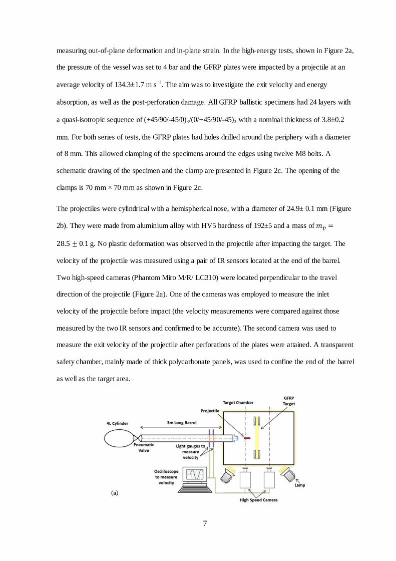
measuring out-of-plane deformation and in-plane strain. In the high-energy tests, shown in Figure 2a,
the pressure of the vessel was set to 4 bar and the GFRP plates were impacted by a projectile at an
average velocity of 134.31.7 m s−1
. The aim was to investigate the exit velocity and energy
absorption, as well as the post-perforation damage. All GFRP ballistic specimens had 24 layers with
a quasi-isotropic sequence of (+45/90/-45/0)3/(0/+45/90/-45)3 with a nominal thickness of 3.80.2
mm. For both series of tests, the GFRP plates had holes drilled around the periphery with a diameter
of 8 mm. This allowed clamping of the specimens around the edges using twelve M8 bolts. A
schematic drawing of the specimen and the clamp are presented in Figure 2c. The opening of the
clamps is 70 mm × 70 mm as shown in Figure 2c.
The projectiles were cylindrical with a hemispherical nose, with a diameter of 24.9± 0.1 mm (Figure
2b). They were made from aluminium alloy with HV5 hardness of 192±5 and a mass of
g. No plastic deformation was observed in the projectile after impacting the target. The
velocity of the projectile was measured using a pair of IR sensors located at the end of the barrel.
Two high-speed cameras (Phantom Miro M/R/ LC310) were located perpendicular to the travel
direction of the projectile (Figure 2a). One of the cameras was employed to measure the inlet
velocity of the projectile before impact (the velocity measurements were compared against those
measured by the two IR sensors and confirmed to be accurate). The second camera was used to
measure the exit velocity of the projectile after perforations of the plates were attained. A transparent
safety chamber, mainly made of thick polycarbonate panels, was used to confine the end of the barrel
as well as the target area.

8
Figure 2. (a) Schematic of gas gun for high velocity impact test, (b) Schemat ic of a target GFRP specimen in
the clamp for ballistic test, (c) Technical drawings of projectile .
A second series of lower energy impact tests were conducted according to the set-up reported by
Kaboglu et al. [31]. The ARAMIS 3D Digital Image Correlation system was used to obtain the full-
field deformation map and major in-plane strains of GFRP composite plates with various matrices
for velocities below the ballistic limit [32]. In these tests as shown in Figure 3a, the two high speed
cameras were moved to the back side of the target separated by a distance of 410 mm and 925 mm
from the centre point of the target and the angle between the two cameras was 25. The back surfaces
of the specimens were illuminated by two halogen lamps to avoid any shadows from nearby objects,
which were turned on a few seconds before the start of firing the projectile. The cameras were used
to record at a rate of 39,000 frames per second. A pair of identical Nikon lenses with a fixed focal
length of 50 mm was used for both cameras. These cameras were triggered simultaneously by the
signal generated from the IR sensors at the beginning of the tests. One side of each specimen was
painted with matt white spray paint to avoid getting reflection of light on the specimen and to
conceal any imperfections on its surface and then speckled by hand using a matt black marker with
the size of the black speckles around 1.5-2.0 mm. The high contrast, randomly generated unique
speckle patterns on each facet were tracked by the ARAMIS software, and the deformation field was
calculated from the sequence of images from the two high-speed cameras and strain was determined
from the calculated displacement.
The three critical length scales associated with DIC are speckle size, facet size, and facet step.
Speckle pattern and size chosen prior to a ballistic test are based upon deformation, features of

9
interest, field-of-view, resolution, and structure length scale [33]. Facet size is the correlation
window, i.e. a relatively small aperture that comprises multiple speckles used for intensity pattern
matching. The last length scale facet step is defined as the facet overlap length usually about 2
pixels. The latter two parameters – facet size and facet step – are chosen during the post-processing
of DIC data. The size of the facets and the level of overlap are very important for measuring the
strain. In this research, the area of the specimen is 70 mm × 70 mm and the image resolution is 256 ×
256 pixels. As a result, each pixel is 0.273 mm and the area of each pixel is 0.07477 mm2. The
recommended minimum speckle size is 5 pixels resulting in speckle area of 0.374 mm2 and diameter
of 0.7 mm. This minimum speckle size is the smallest readable size by the software. Anything larger
is acceptable. In this research, the speckle has diameter of 1.5 mm resulting in approximately 1.77
mm2 area, roughly 4.7 times the minimum acceptable size. The accuracy of strain is ca. 0.05% under
best condition. Black and white paints were chosen to maximise contrast. An example of a specimen
with a typical speckle pattern is shown in Figure 3b.
The projectiles used for these experiments were the same as in the first series of ballistic tests. In this
series of tests, the pressure of the vessel was set to 1.5 bar and the GFRP plates were impacted by a
projectile at an incident velocity of 761 m s−1
(equivalent to 273.6 km/h) which resulted in all
projectiles rebounding back. This speed is the upper limit in automotive accidents. The projectiles
were retrieved after the impact tests, and after inspection, no plastic deformation of the projectile
following impact was observed and almost all the impact energy was absorbed by the target plates.
(a)

10
(b)
Figure 3. (a) Schematic of gas gun for high velocity impact test with 3D DIC, (b) a GFRP specimen with a
speckle pattern before ballistic test.
3.2. Ballistic test results and discussion
3.2.1. Results of perforated ballistic tests
In this series of tests, all specimens were perforated under ballistic impact with an average velocity
of 134.31.7 m s−1
(equivalent to 482.4 km/h). Commercial aircraft approaching landing has speed
around this range and bird strike is likely impact event during approach to landing. Following impact
testing, the panels were visually inspected for damage. There was noticeably more damage on the
rear face of the GFRP with (EP+BNNS+CNT) matrix compared to the other matrices, which showed
little clear difference between them. Across all the specimens, similar behaviour in the crack
propagation was observed along the fibre in ±45 direction as seen from the rear surface of impacted
specimens.
The exit velocity (Ve) of the projectiles in this series of tests together with the percentage in reduction
of incident velocity (Vi) is shown in Figure 4a. The results show that all nanomodified epoxy
matrices have reduced the exit velocity relative to the neat epoxy. The GFRP with neat epoxy
experienced a reduction in the exit velocity by 67%, from 131.6 m s-1
to 43.4 m s-1
.The highest
reduction in the exit velocity was achieved by GFRP with (EP+BNNT+GNP) modified matrix. This
matrix reduced the incident velocity by 89.1% from 135 m s-1
to 14.7 m s-1
. Therefore, GFRP with
(EP+BNNT+GNP) matrix contributed an additional 22.1% to the reduction of exit velocity on top of
the reduction in exit velocity in GFRP with unmodified epoxy matrix.
The absorbed energy (E) and specific energy absorption (SEA) were calculated from

11
(1)
(2)
The highest absolute absorbed energy was observed for the instance of the GFRP with
(EP+BNNT+GNP) matrix at 255.7 J, 16.8% higher than the unmodified epoxy matrix. However, the
(EP+BNNT+GNP) specimen was heavier than the neat epoxy specimen. The mass of glass fabric
( in both specimens was the same and the difference is due to the surplus of matrix (see
Table 1). The (EP+BNNT+GNP) specimen had 8.7% more resin than the neat epoxy specimen. This
effect can be compensated for by comparing specific energy absorption (SEA) for all specimens in
Table 1 and Figure 4b. It is evident that even with this adjustment, all nanomodified GFRPs have
higher SEA than unmodified GFRP, but the best performing matrix based on the SEA criteria is
(EP+BNNS+CNT) with 16.3% higher SEA than the unmodified epoxy matrix. Overall, the average
increase in SEA for nanomodified epoxy GFRPs relative to unmodified epoxy GFRP is 11.4%. It is
evident that the change in the fibre volume fraction had a direct effect on the exit velocity. The
(EP+BNNT+GNP) specimen had 8.7% more resin relative to the unmodified epoxy specimen. It is
reported that stick-slip frictional motion between the nanoparticles and the epoxy resin is the source
of interface damping [34] and debonding slippage occurring between nanoparticles and the matrix
under external force, resulting in interface friction, which in turn led to energy dissipation [35]. The
reduction in exit velocity seen for (EP+BNNT+GNP) specimen is partly due to the excess resin, as
polymers have a damping effect on the projectile.
Table 1. Summary of perforated ballistic tests results
Matrix
(g)
(g)
Vi
(m s-1
)
Ve
(m s-1
)
% of
decrease in Ve
Absorbed
energy (J)
SEA
(kJ kg-1
)
% change of
SEA relative
to neat
epoxy
Neat epoxy 123.4 28.4 131.6 43.6 67.0 218.9 1.77 -
EP+GNP 121.8 28.4 135 30.6 77.3 245.5 2.02 +13.6
EP+CNT 132.2 28.5 135 20.1 85.1 253.9 1.92 +8.3
EP+BNNS+CNT 121.5 28.4 135 23.9 82.3 250.7 2.06 +16.3
EP+BNNT+GNP 134.1 28.4 135 14.7 89.1 255.7 1.91 +7.5

12
(a)
(b)
Figure 4. Effect of nanomaterials on (a) reduction of exit velocity, and (b) specific energy absorption by GFRP
plates in perforating ballistic tests.
3.2.2. Unperforated ballistic tests
Figure 5 shows the variations of major strains along the centre line (CL) at the end of loading (when
projectile has come to a stop) and at the end of the unloading (when the projectile loses contact with
the panel) for all specimens with different matrices. The duration of the impact for all specimens was
identical. It is noticeable that in the loading cycle the epoxy behaved as the most compliant laminate
with the highest strains. At the end of unloading, the average residual strain in the neat epoxy
specimen is also the highest, showing the most permanent damage occurring within this specimen.
The minimum residual strain at the end of the test is attributed to the GFRP with (EP+BNNT+GNP)
matrix, demonstrated by the minimum permanent damage.
0
20
40
60
80
100
EP
EP
+G
NP
EP
+C
NT
EP
+B
NN
S+
CN
T
EP
+B
NN
T+
GN
P
Exit velocity (m/s)- perforating tests
% reduction in incident velocity
0
0.5
1
1.5
2
2.5
EP
EP
+G
NP
EP
+C
NT
EP
+B
NN
S+
CN
T
EP
+B
NN
T+
GN
P
Sp
ecific
En
erg
y A
bso
rptio
n (
kJ/k
g)

13
(a)
(b)
Figure 5. Principal strain at the end of (a) loading and (b) unloading for all specimens.
In Figure 6a, the out-of-plane displacement maps of the five different specimens during loading and
unloading are compared. The duration of the impact for all specimens is the same. However, the
maximum out-of-plane displacement areas (shown in red) are different and it is at minimum for
specimen with (EP+BNNT+GNP) matrix. The map of major strain distribution during 0.4 ms impact
duration is shown Figure 6b.
(a)
0
1
2
3
4
-25 -15 -5 5 15 25
Neat epoxyEP+GNPEP+CNTEP+BNNS+CNTEP+BNNT+GNP
Pri
ncip
al str
ain
at
the
en
d o
f lo
ad
ing
(%
)
Horizontal distance along the plate (mm)
LoadingCL
-0.2
0
0.2
0.4
0.6
0.8
-25 -15 -5 5 15 25
Neat epoxyEP+GNPEP+CNTEP+BNNS+CNTEP+BNNT+GNP
Pri
ncip
al str
ain
at
the
en
d o
f u
nlo
ad
ing
(%
)
Horizontal distance along the plate (mm)
UnloadingCL

14
(b)
Figure 6. DIC fu ll field images of (a) out-of-p lane deformation and (b) major strain of GFRP laminated plates
during ballistic impact with different epoxy nanocomposites under incident velocity of 761 m s-1
when
projectile rebounded.
Figure 7 illustrate the post-impacted images of the front and rear surfaces of the GFRP plates for
neat epoxy and various nanocomposite matrices. The damage in laminate with (EP+BNNS+CNT)
matrix is noticeably the highest and for (EP+GNP), (EP+CNT) and (EP+BNNT+GNP) matrices are
relatively lower. The main energy-dissipation mechanisms observed during ballistic impact were: (i)
localised fibres tearing along the projectile path due to the out-of-plane shear stresses induced by the
projectile, (ii) propagation of interply delamination cracks across the plate from the impacted region
(see Figure 8), (iii) spread of matrix crushing and cracking over a larger area along the projectile
path, and (iv) tensile fibre failure at the back layers.

15
Figure 7. Images of front and rear faces of impacted GFRP laminates with (a) neat epoxy, (b) EP+GNP, (c)
EP+CNT, (d) EP+BNNS+CNT and (e) EP+BNNT+GNP matrices.
4. Post-ballistic impact damage assessment using pulse infrared thermography
Among various non-destructive testing (NDT) techniques, active thermography techniques and
specifically pulsed infrared thermography (PT) has shown great potential. This technique has a fast
inspection rate capability. The system is contactless, has high spatial resolution and sensitivity, with
internal defect detectability using heat conduction [36].
In this work, the extent of the damage in the GFRP specimens after post-ballistic tests is examined
by flash-pulse infrared thermography. The flash thermography system used in this project was a
Phoenix Medium Wavelength Infrared (MWIR) camera (FLIR systems), recording the IR emissions
from the surface of the specimen at 50 Hz frame rate with a Thermal wave commercial image
processing software package called MOSAIQ [37]. A Xenon flash tube lamp with energy output of
2 kJ were used to generate pulsed thermal waves with total pulse duration lasting 30 ms. When this
pulsed thermal energy is applied, a thin layer of material on the surface is heated by a few degrees

16
centigrade. The surface temperature decays as heat is transferred by conduction through the
specimen [38, 39]. The presence of any discontinuities such as delaminations in the laminate hinders
the heat transfer locally. As a result, the surface cooling rate adjacent to the defects is reduced and
temperature above discontinuities remains higher than the undamaged areas. The IR camera captures
the surface temperature evolution during the entire thermal transient period. The contrast in surface
temperature distribution above the defects in comparison with the surface temperature over
undamaged areas is used to determine the location and the size of defects such as delaminations. In
these series of tests, the lamps and the IR camera were located on the same side of the specimen. The
MOSAIQ software is used to control the camera and flash unit to acquire a short video clip around
2 min long. From the video clips, the location, shape and size of the defect can be measured from the
temperature distribution on the surface of the inspected structure. By monitoring changes as a
function of time, the depth of defects can also be inferred, with deeper defects observed later, and
with a reduced contrast. The elapsed time is approximately a function of the square of the depth
and the loss of contrast is proportional to the inverse of the cube of the depth [40], i.e.
and where is thermal diffusivity of the material, the density of the
material, heat capacity and thermal conductivity [41].
4.1. Test results
The PT images of the first derivatives [42] of heat amplitude with respect to time from the post-
ballistic tests with projectile penetration are shown in Figure 8 and Figure 9. The plane slice
images of the raw, the first and second logarithmic derivatives at time 2.29 s shown in
Figure 8 demonstrate that the raw data images do not accurately identify the damage areas.

17
Figure 8. Raw (left), 1st
(centre) and 2nd
time differential (right) images of perforated GFRP plates obtained
2.29 s after the flash on GFRP p lates with (EP+BNNT+GNP) matrices.
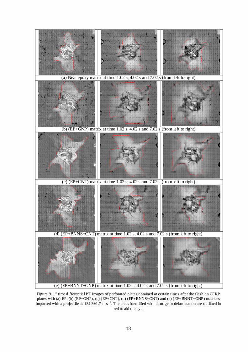
Figure 9 shows the first logarithmic derivatives at time 1.02 s, 4.02 s and 7.02 s after the flash
showing the delaminated areas were spread from the point of impact. The thermal diffusivity of
GFRP is about mm2
s-1
[43]. Therefore, the images’ time are equivalent to looking at the
depths close to the front, mid-plane and back surface of the plates, which have an average thickness
of 3.80.2 mm. Note however that information from other depths will also be visible in a given
frame.
The PT images reveal that the ballistic impact damages are localised around the point of the
projectile impact. Visual inspection revealed that there was no evidence of damage on the surface of
the laminates except at the projectile impact area and its proximity. All delamination can be observed
from the raw thermal images as ‘hot spots’, but the thermal contrast of smaller or deeper
delaminations is very weak in the raw images. The contrast intensity of the delaminations in the first
derivatives images is very good, and they show the extent of delamination. The first derivatives are
at the peak in part of delamination area, while the peaks for other shallower delamination occurred at
shallower depths (or earlier times).
As shown in Table 1 the highest energy absorption occurred in GFRP with (EP+BNNT+GNP)
matrix. This is consistent with the PT images for this GFRP in Figure 9e showing the highest
delamination area in many layers. The minimum damage occurred in neat epoxy GFRP (see Figure
9a), the projectile entered and left the specimen with minimum energy absorption by the laminate.
The extents of the damage shown in Figure 9 are matching the energy absorption value reported in
Table 1 for all types of laminates.
18
(a) Neat epoxy matrix at time 1.02 s, 4.02 s and 7.02 s (from left to right).
(b) (EP+GNP) matrix at time 1.02 s, 4.02 s and 7.02 s (from left to right).
(c) (EP+CNT) matrix at time 1.02 s, 4.02 s and 7.02 s (from left to right).
(d) (EP+BNNS+CNT) matrix at time 1.02 s, 4.02 s and 7.02 s (from left to right).
(e) (EP+BNNT+GNP) matrix at time 1.02 s, 4.02 s and 7.02 s (from left to right).
Figure 9. 1st
time d ifferential PT images of perforated plates obtained at certain times after the flash on GFRP
plates with (a) EP, (b) (EP+GNP), (c) (EP+CNT), (d) (EP+BNNS+CNT) and (e) (EP+BNNT+GNP) matrices
impacted with a projectile at 134.31.7 m s−1
. The areas identified with damage or delamination are outlined in
red to aid the eye.

19
5. Conclusions
In the present work, the effect of the modification of GFRP with additive nanoparticles to the epoxy
matrix undergoing ballistic impact has been investigated. GNP, CNT, hybrid BNNS+CNT and
hybrid BNNT+GNP are used to modify the epoxy matrix.
The ballistic impact tests at two projectile velocities were carried out on the GFRP made from non-
crimp quasi-isotropic lay-up of [(45/90/-45/0)3/(0/45/90/-45)3] with different types of resins. At a
projectile velocity of 761 m s−1
the full-field deformation and major strain are measured without
introducing any visible impact damage using DIC system. At a projectile velocity of 134.31.7 m s−1
all GFRP laminated specimens were perforated.
The ballistic tests results showed that different nanoparticles within the matrix have an effect on the
impact behaviour and damage mechanisms of the GFRP composites. All nanomodified epoxy
GFRPs recorded exit velocities lower than neat epoxy GFRP at an incident velocity of 134.31.7 m
s−1
. The neat epoxy GFRP specimen reduced the exit velocity by 67%, from 131.6 m s-1
to 43.4 m s-
1.The highest reduction in exit velocity was achieved in the instance of the GFRP with
(EP+BNNT+GNP) modified matrix. This matrix reduced the incident velocity by 89.1%, an
additional 18.1% reduction of exit velocity on top of the reduction in exit velocity with the neat
epoxy GFRP. Overall, the average increase in specific energy absorption (SEA) achieved for
nanomodified epoxies GFRPs relative to the neat epoxy GFRP was 11.4%.
Non-destructive flash-pulsed thermography was employed for post-impact analysis. The images
from this method showed that the damage was localised and limited to areas around the impacted
point with internal delaminations. To conclude, the incorporation of the various nanoparticles into
the epoxy system resulted in a reduction in the exit velocities as well as providing further
enhancement in the energy absorption.
Acknowledgements
Dr Nadiim Domun much appreciates the Faculty of Science, Engineering and Computing (SEC) of
Kingston University London and the National Physical Laboratory (NPL) for the financial support

20
provided for his PhD study. Dr Cihan Kaboglu much appreciates the Turkish Government for the
PhD scholarship and EDF Energy for financial support. Dr Jun Liu much appreciates the Aviation
Industry Corporation of China (AVIC) First Aircraft Institute (FAI), through AVIC Centre for
Structural Design and Manufacture at Imperial College London, for financial support. Dr Keith R.
Paton acknowledges funding provided by the National Measurement System of the U.K. Department
of Business, Enterprise and Industrial Strategy.
References
[1] O. Balcıa, O. Çobanb, M. Ö. Borab, E. Akagündüzc and E. B. Yalçin, “Experimental investigation of single and repeated impacts for repaired honeycomb sandwich structures,” Materials Science and Engineering: A, vol. 682, pp. 23-30, 2017.
[2] X. Cai, P. Pan, J. Zhu and R. Gu, “The analysis of the aerodynamic character and structural response of large-scale wind turbine blades,” Energies, vol. 6, no. 7, pp. 3134-3148, 2013.
[3] D. Brosius, “Boeing 787 Update”, High-Performance Composites,” http://www.compositesworld.com/articles/boeing-787-update, 2007.
[4] M. S. H. Fatt and C. Lin, “Perforation of clamped, woven E-glass/polyester panels,” Compos B Eng, vol. 35, no. 5, pp. 359-378, 2004.
[5] T. R. Walter, G. Subhash, B. Sankar and C. Yen, “Damage modes in 3D glass fiber epoxy
woven composites under high rate of impact loading,” Compos B Eng, vol. 40, no. 6, pp. 584-589, 2009.
[6] M. A. Meyers, Dynamic behavior of materials, New York: John Wiley & Sons, 1994.
[7] S. Abrate, Impact of composite structures, New York: Cambridge University Press, 1998.
[8] R. Sikarwar, R. Velmurugan and N. K. Gupta, “Influence of fiber orientation and thickness on
the response of glass/epoxy composites subjected to impact loading,” Compos B Eng, vol. 60, pp. 627-636, 2014.
[9] H. Ahmadi, G. H. Liaghat, H. Sabouri and E. Bidkhouri, “Investigation on the high velocity
impact properties of glass-reinforced fiber metal laminates,” Journal of Composite Materials,
vol. 47, no. 13, pp. 1605-1615, 2013.
[10] R. S. Reddy, T. S. Reddy, V. Madhu, A. K. Gogia and K. V. Rao, “Behavior of E-glass
composite laminates under ballistic impact,” Materials & Design, vol. 84, no. 5, pp. 79-86, 2015.
[11] E. K. C. Rolfe, R. Quinn, P. A. Hooper, H. Arora and J. P. Dear, “High Velocity Impact and
Blast Loading of Composite Sandwich Panels with Novel Carbon and Glass Construction,” Journal of Dynamic Behavior of Materials, vol. 4, no. 3, pp. 359-372, 2018.

21
[12] S. K. Garcia-Castillo, C. Navarro and E. Barbero, “Damage in preloaded glass/vinylester
composite panels subjected to high-velocity impacts,” Mech Res Commun, vol. 55, pp. 66-71, 2014.
[13] M. M. Ansari, A. Chakrabarti and M. A. Iqbal, “An experimental and finite element
investigation of the ballistic performance of laminated GFRP composite target,” Compos B Eng, vol. 125, pp. 211-226, 2017.
[14] M. S. Hoo Fatt, C. Lin, D. M. Revilock and D. A. Hopkins, “Ballistic impact of GLARE™ fiber–metal laminates,” Composite Structures, vol. 61, no. 1-2, pp. 73-88, 2003.
[15] G. S. E. Bikakis, C. D. Dimou and E. P. Sideridis, “Ballistic impact response of fiber–metal
laminates and monolithic metal plates consisting of different aluminum alloys,” Aerospace
Science and Technology, vol. 69, pp. 201-208, 2017.
[16] N. Domun, K. R. Paton, H. Hadavinia, T. Sainsbury, T. Zhang and H. Mohamud,
“Enhancement of fracture toughness of epoxy nanocomposites by combining nanotubes and nanosheets as fillers,” Materials, vol. 10, no. 10, p. 1179, 2017.
[17] R. B. Ladani, M. Bashin, S. Wu, A. R. Ravindran, K. Ghorbani, J. Zhang, A. J. Kinloch and et
al., “Fracture and fatigue behaviour of epoxy nanocomposites containing 1-D and 2-D nanoscale
carbon fillers,” Engineering Fracture Mechanics, p. doi.org/10.1016/j.engfracmech.2018.04.033, 2018.
[18] S. Chatterjee, F. Nafezarefi, N. H. Tai, L. Schlagenhauf and et al., “Size and synergy effects of
nanofiller hybrids including graphene nanoplatelets and carbon nanotubes in mechanical
properties of epoxy composites,” Carbon, vol. 50, pp. 5380-5386, 2012.
[19] W. Li, A. Dichiara and J. Bai, “Carbon nanotube–graphene nanoplatelet hybrids as high-
performance multifunctional reinforcements in epoxy composites,” Composites Science and Technology, vol. 74, pp. 221-227, 2013.
[20] S.-Y. Yang, W.-N. Lin, Y.-L. Huang, H.-W. Tien, J.-Y. Wang, C.-C. Ma, S.-M. Li and Y.-S.
Wang, “Synergetic effects of graphene platelets and carbon nanotubes on the mechanical and thermal properties of epoxy composites,” Carbon, vol. 49, no. 3, pp. 793-803, 2011.
[21] B. Johnsen, A. J. Kinloch, R. D. Mohammed, A. C. Taylor and S. Sprenger, “Toughening mecahnisms of nanoparticle-modified epoxy polymers,” Polymer, pp. 530-541, 2007.
[22] M. Tehrani, A. Y. Boroujeni, T. B. Hartman, T. P. Haugh, S. W. Case and M. S. Al-Haik,
“Mechanical characterization and impact damage assessment of a woven carbon fiber reinforced carbon nanotube-epoxy composite,” Compos Sci Technol, vol. 75, pp. 42-48, 2013.
[23] S. Laurenzi, R. Pastore, G. Giannini and M. Marchetti, “Experimental study of impact
resistance in multi-walled carbon nanotube reinforced epoxy,” Compos Struct, vol. 99, pp. 62-
68, 2013.
[24] M. Rahman, M. Hosur, S. Zainuddin, U. Vaidya, A. Tauhid and A. Kumar, “Effects of amino-
functionalized MWCNTs on ballistic impact performance of E-glass/epoxy composites using a spherical projectile,” Int. J. Impact Eng., vol. 57, pp. 108-118, 2013.
[25] N. K. Naik, K. S. Pandya, V. R. Kavala, W. Zhang and N. A. Koratkar, “High-strain rate
compressive behavior of multi-walled carbon nanotube dispersed thermoset epoxy resin,”

22
Journal of Composite Materials , vol. 49, no. 8, pp. 903-910, 2015.
[26] K. S. Pandya and N. K. Naik, “Analytical and experimental studies on ballistic impact
behaviour of carbon nanotube dispersed resin,” Int. J. Impact Eng., vol. 76, pp. 49-59, 2015.
[27] M. H. Pol, G. Liaghat, E. Zamani and A. Ordys, “Investigation of the ballistic impact behavior
of 2D woven glass/epoxy/nanoclay nanocomposites,” Journal of Composite Materials, vol. 49, no. 12, pp. 1449-1460, 2014.
[28] M. Pol, G. H. Liaghat and F. Hajiarazi, “Effect of nanoclay on ballistic behavior of woven
fabric composites: Experimental investigation,” Journal of Composite Materials, vol. 47, no. 13, pp. 1563-1573, 2012.
[29] A. Avila, A. Neto and H. Nascimento Jr., “Hybrid nanocomposites for mid-range ballistic protection,” Int. J. Impact Eng., vol. 38, pp. 669-675, 2011.
[30] N. Domun, H. Hadavinia, T. Zhang, G. H. Liaghat, S. Vahid, K. Paton, C. Spacie and T.
Sainsbury, “Improving the fracture toughness properties of epoxy using graphene nanoplatelets at low filler content,” Nanocomposites, vol. 3, no. 3, pp. 85-96, 2017.
[31] C. Kaboglu, I. Mohagheghian, J. Zhou, Z. Guan, W. Cantwell, S. John, B. R. K. Blackman, A.
J. Kinloch and J. P. Dear, “High-velocity impact deformation and perforation of fibre metal laminates,” Journal of Material Science, vol. 53, no. 6, p. 4209–4228, 2018.
[32] “ ARAMIS User Manual – Software v6.3,” ARAMIS, GOM mBH, Braunschweig Germany , 2011.
[33] V. Rajan, M. Rossol and F. Zok, “Optimization of digital image correlation for high-resolution
strain mapping of ceramic composites,” Experimental Mechanics, vol. 52, no. 9, pp. 1407-21, 2012.
[34] X. Zhou, E. Shin, K. W. Wang and C. E. Bakis, “Interfacial damping characteristics of carbon
nanotube-based composites,” Composite Science Technology, vol. 64, no. 15, pp. 2425-2437, 2004.
[35] A. Buldum and P. L. Jian, “Atomic Scale Sliding and Rolling of Carbon Nanotubes,” Phys Rev Lett, vol. 83, no. 24, pp. 5050-5053, 1999.
[36] B. Liu, H. Zhang, H. Fernandes and X. Maldague, “Quantitative evaluation of pulsed
thermography, lock-in thermography and vibrothermography on foreign object defect (FOD) in
CFRP,” Sensors, vol. 16, p. 743, 2016.
[37] “Thermal Wave Imaging,” [Online]. Available: https://www.thermalwave.com/1/376/mosaiq.asp. [Accessed 04 09 2018].
[38] G. Kidd and J. Nunn, “Application of pulsed thermography to quality assurance of thermal barrier coatings,” Proc. IMechE Part G: J. Aerospace Engineering, vol. 226, pp. 873-880, 2011.
[39] J. Sun, “Analysis of data processing methods for pulsed thermal imaging characterisation of delaminations,” Quantitative InfraRed Thermography Journal, vol. 10, pp. 9-25, 2013.
[40] X. P. Maldague, Theory and practice of infrared technology for non-destructive testing, New York: John Wiley Interscience, 2001.

23
[41] H. Czichos, Handbook of Technical Diagnostics, Germany: Springer Verlag: Berlin/Heidelberg, 2013.
[42] Z. Zeng, N. Tao, L. C. Feng, Y. S. Li and C. L. Zhang, “Relative thermal contrast analysis in the
inspection of wind turbine blades using pulsed thermography,” Adv. Mater. Res. , Vols. 301-303, pp. 591-596, 2011.
[43] G. Wróbel, S. Pawlak and G. Muzia, “Thermal diffusivity measurements of selected fiber
reinforced polymer composites using heat pulse method,” Archives of Materials Science and Engineering, vol. 48, no. 1, pp. 25-32, 2011.