· 2020-06-16 · outline of lubrication systems pumps pumps pumps pumps pumps pumps valves valves...
TRANSCRIPT

LHL+
GREASE-
SYSTEMS
OIL-
SYSTEMS
TUBING
PARTS
SERVICE
LUBE ORIGINAL CATALOGAutomatic lubrication systems
1
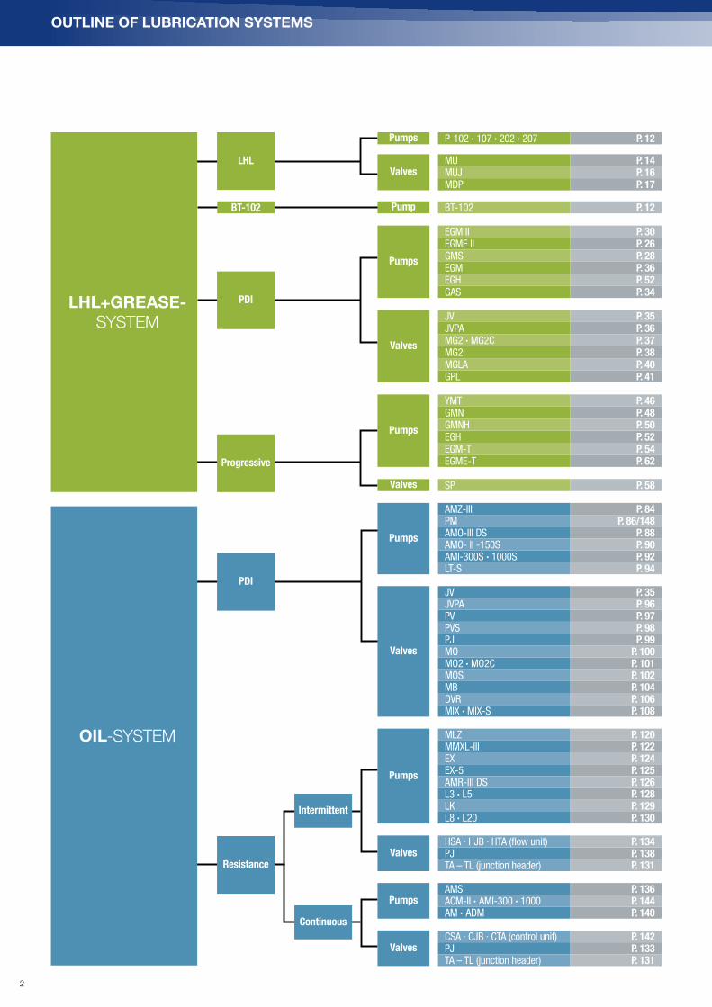
OUTLINE OF LUBRICATION SYSTEMS
Pumps
Pumps
Pumps
Pumps
Pumps
Pumps
Valves
Valves
Valves
Valves
Valves
Valves
LHL+GREASE- SYSTEM
OIL-SYSTEM
LHL
PDI
Progressive
Resistance
Intermittent
Continuous
P-102 · 107 · 202 · 207 P. 12
MU P. 14MUJ P. 16MDP P. 17
BT-102 P. 12
EGM II P. 30EGME II P. 26GMS P. 28EGM P. 36EGH P. 52GAS P. 34
JV P. 35JVPA P. 36MG2 · MG2C P. 37MG2I P. 38MGLA P. 40GPL P. 41
YMT P. 46GMN P. 48GMNH P. 50EGH P. 52EGM-T P. 54EGME-T P. 62
SP P. 58
AMZ-III P. 84PM P. 86/148AMO-III DS P. 88AMO- II -150S P. 90AMI-300S · 1000S P. 92LT-S P. 94
JV P. 35JVPA P. 96PV P. 97PVS P. 98PJ P. 99MO P. 100MO2 · MO2C P. 101MOS P. 102MB P. 104DVR P. 106MIX · MIX-S P. 108
MLZ P. 120MMXL-III P. 122EX P. 124EX-5 P. 125AMR-III DS P. 126L3 · L5 P. 128LK P. 129L8 · L20 P. 130
HSA · HJB · HTA (flow unit) P. 134PJ P. 138TA – TL (junction header) P. 131
AMS P. 136ACM-II · AMI-300 · 1000 P. 144AM · ADM P. 140
CSA · CJB · CTA (control unit) P. 142PJ P. 133TA – TL (junction header) P. 131
PDI
PumpBT-102
2

LHL System Battery operated grease pump kit Multi-Port Centralized Lubrication System
P-102/107/202/207
EGM II EGME II BT-102 YMT
P. 12 P. 24 P. 26 P. 14 P. 46
Positive Displacement Injector (PDI) System for Small-Medium Machines
GMS-4-3P GMS-4-8P EGM-10S-4-4C EGM-10S-4-7C EGH-3P EGH-2C EGH-4C GAS-8P MU
P. 28 P. 28 P. 30 P. 30 P. 52 P. 52 P. 52 P. 34 P. 15
MUJ MDP MG2 . MG2C JPVA MG2I MGLA GPL JV
P. 16 P. 17 P. 37 P. 36 P. 38 P. 40 P. 41 P. 35
Series Progressive System for Small-Large Machines
GMN-4-8P GMNH-4-4C GMNH-2-4C GMNH-4-7C GMNH-1-7C/2-7C EGH-3P EGH-2C EGH-4C SP
P. 48 P. 50 P. 50 P. 50 P. 50 P. 52 P. 52 P. 52 P. 58
Compatible with Both PDI and Series Progressive Metering Valve System for Small-Medium Machine LUBE original grease
EGM-10T-4-7C EGME-10T-4-2CMP0 . FS2 .
LFL . Y52 . CBTLHL-X100/300
P. 54 P. 62 P. 63 P. 62
Accessories
Controller Pressure gaugePneumatic pump
for pail Grease gun
Grease vacuumcleaner
Steel dust meter
Solenoid valve Filter regulator
P. 66 P. 68 P. 69 P. <?> P. 76 P. 77 P. 78 P. 78
LHL + Grease-System
3
OUTLINE OF LUBRICATION SYSTEMS
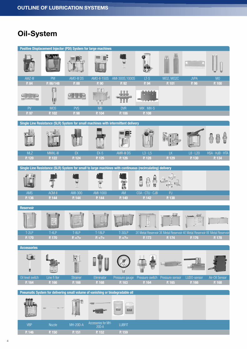
Oil-System
Positive Displacement Injector (PDI) System for large machines
AMZ-III PM AMO-III DS AMO-II-150S AMI-300S,1000S LT-S MO2, MO2C JVPA MO
P. 84 P. 86/148 P. 88 P. 90 P. 92 P. 94 P. 101 P. 96 P. 100
PV MOS PVS MB DVR MIX . MIX-S
P. 97 P. 102 P. 98 P. 104 P. 106 P. 108
Single Line Resistance (SLR) System for small machines with intermittent delivery
MLZ MMXL-III EX EX-5 AMR-III DS L3 · L5 LK L8 · L20 HSA · HJB · HTA
P. 120 P. 122 P. 124 P. 125 P. 126 P. 128 P. 129 P. 130 P. 134
Single Line Resistance (SLR) System for small to large machines with continuous (recirculating) delivery
AMS ACM-II AMI-300 AMI-1000 AM CSA · CTU · CJB PJ
P. 136 P. 144 P. 144 P. 144 P. 140 P. 142 P. 138
Reservoir
T-2LP T-4LP T-8LP T-18LP T-30LP 2ℓ Metal Reservoir 3ℓ Metal Reservoir 4ℓ Metal Reservoir 8ℓ Metal Reservoir
P. 170 P. 170 P. <?> P. <?> P. <?> P. 173 P. 174 P. 176 P. 178
Accessories
Oil level switch Line fi lter Strainer Eliminator Pressure gauge Pressure switch Pressure sensor LUDO-sensor Air-Oil Sensor
P. 164 P. 166 P. 166 P. 168 P. 163 P. 164 P. 165 P. 166 P. 168
Pneumatic System for delivering small volume of vanishing or biodegradable oil
VBP Nozzle MH-20D-AAccessories for MH-
20D-ALUBFIT
P. 146 P. 150 P. 151 P. 152 P. 159
4

Old product Updated product
Model Part No. Part No. Model Changes from the last time
GHS-4C-B 103535 → 103781*1 EGH-4C-BDepressurizing lever operation is no longer necessary.Weight is lighter, but the mounting dimensions are thesame. When the lever is pulled, grease is discharged (whenthe lever of GHS is pushed, grease is discharged).
GHS-4C 103536 → 103782 EGH-4C
GHS-3P 103501 → 103783 EGH-3P
GHN-4C-B 103537 → 103781*1 EGH-4C-B Weight is lighter, but the mounting dimensions are thesame. When the lever is pulled, grease is discharged (whenthe lever of GHS is pushed, grease is discharged).
GHN-4C 103538 → 103782 EGH-4C
GHN-3P 103503 → 103783 EGH-3P
GMS-20-80-CB-4L 103539 → 103810 EGM-10S-4C There is the built-in depressurization solenoid, so stabledepressurization becomes possible. Since the mountingdimensions are different, contact us for a consultation.GMS-20-80-CB-7L 103570 → 103811 EGM-10S-7C
GMS-20-80-CB-TS-4L 103546 → 103810 EGM-10S-4C Since the mounting dimensions are different, contact us for a consultation.GMS-20-80-CB-TS-7L 103546 → 103811 EGM-10S-7C
AMO-II -150S(With controller)
*2 → *2 AMO-III DSSetting the time accurately is possible by seeing LCDscreen displays on the operation side.
AMR-II -150S(With controller)
*2 → *2 AMR-III DSSetting the time accurately is possible by seeing LCDscreen displays on the operation side.
AMZ100S(With controller)
*2 → *2 AMO-III DSSetting the time accurately is possible by seeing LCDscreen displays on the operation side. Since the mountingdimensions are different, contact us for a consultation.
AMZ100S(Without controller)
*2 → *2 AMZ-III Lightweight and low cost become possible. Since themounting dimensions are different, contact us for a consultation.
Tubing parts (Grease system)
Compression Parts
Plugging parts Tubing parts Tube clips Flexible Hose Adapters Connectors Coupling parts Push in fitting
P. 182 P. 189 P. 190 P. 185 P. 192 P. 194 P. 192 P. 194 P. 195
Application brushes
Universal elbow connector
Fittings Swivel fittings Jet nozzle Sight feed Indicator pin Drive bushing
P. 196 P. 197 P. 198 P. 200 P. 200 P. 201 P. 201 P. 202
Alternate product information
*1 Contact LUBE for a consultation. *2 There are multiple specifications difference such as discharging pressure and/or Reservoir capacity.
Tubing parts
5

ABOUT US
LUBE Corporation 4
Global Service Network 6
OUTLINE OF LUBRICATION SYSTEMS 8
LHL + Grease-System 9
Oil-System 10
Tubing parts 11
Alternate product information 11
LHL-SYSTEMS 15
Layouts 16
P-102/107/202/207 (Electric pump) 18
BT-102 (Battery operated grease pump kit) 20
S-Series MU (Metering valves) 21
MUJ (Valve junctions & special fittings) 22
S-Series MDP (Metering valves) 23
PDI-SYSTEMS 25
Layouts 26
EGM II (Pump) 30
EGME II (Pump) 32
GMS (Pump) 34
EGM (Pump)) 36
EGH (Manually operated pump) 38
GAS ((Pneumatic grease pump) 40
JV (Junction) 41
JVPA (Junctions and special fittings for MO2 series) 42
MG2 · MG2C (Metering valve) 43
MG2I (Metering valve with clogged line detection) 44
MGLA (Metering valve with electronic performance monitoring) 46
GPL (Pressure switch) 47
PROGRESSIVE-SYSTEMS 49
Layouts 50
YMT (Cartridge type grease pump) 52
Specified LUBE Original Grease 53
Pump controller 53
GMN (Motorized grease pump) 54
GMNH (High pressure type) 56
EGH (Manual grease pump) 58
EGM-T (Dual-function motorized pump) 60
EGME-T (Dual-function motorized pump) 62
SP (Valve) 64
GREASE 67
LHL (LUBE Hybrid Lubricant) 68
LUBE Original-Grease 69
ACCESSORIES 71
Controller 72
Pump mounting panel 72
Pressure gauge 74
Grease filler pump 75
Grease vacuum cleaner 76
Proximitiy sensor for series progressive valves 77
Steel dust meter 77
Solenoid valve 78
Filter regulator 78
Pumping unit 80
OIL-SYSTEMS (PDI) 83
Layouts 84
AMZ-III (Automatic intermittent gear pump) 90
PM-8S (Piston pump) 92
AMO–III DS (Automatic intermittent gear pump) 94
AMO-II-150S (Automatic intermittent gear pump) 96
AMI-300S AMI-1000S (Automatic intermittent gear pumps) 98
LT-S (Manually operated intermittent piston pump) 100
JV (Junction) 101
JVPA (Junctions and special fittings for MO2 series) 102
PV (Junction for MO valve) 103
PVS (Junction for MOS compact metering valve) 104
PJ (Junction for main tubing) 105
MO (Metering valve) 106
MO2 · MO2C (Metering valve) 107
MOS (Compact metering valve) 108
MB (Spring piston metering valve) 110
DVR (Adjustable PDI valve)) 112
MIX · MIX-S (Air-oil metering valve) 114
OIL-SYSTEMS (SLR) 119
Layouts 120
Oil application overview 124
MLZ (Automatic intermittent piston pump) 126
MMXL-III (Automatic intermittent piston pump) 128
EX (Solenoid driven intermittent piston pump) 130
EX-5 (Solenoid driven intermittent piston pump) 131
AMR-III DS (Automatic intermittent gear pump) 132
Contents
6

L3 · L5 (Manually operated piston pump) 134
LK (Manually operated piston pump) 135
L8 · L20 (Manually operated piston pump) 136
TA · TB · TC · TD · TH · TK · TL (Junction header) 137
PJ (Junction) 138
PJ (Junction) 139
HSA · HJB · HTA · HTD · HTC · HTB (Flow unit) 140
AMS (Automatic small discharge volume gear pump) 142
ACM-II · AMI-300 · AMI-1000 (Motor driven gear pumps) 144
AM (Automatic intermittent gear pump) 146
CSA · CJB · CTA · CTD · CTC · CTB (Control unit) 148
PNEUMATIC SYSTEMS 151
VBP (Pump for delivering small volumes of biodegradable oil) 152
PM-8S (Piston Pump) 154
VOA (Flexible pipe nozzle with metering valve) 156
MIB (Mixing block for VBP-Pump) 156
FDM (Flexible pipe nozzle with metering valve) 156
MH-20D-A (Spay cooling system) 157
Accessories for MH-20D-A pump 158
LF 53 · LF 55 · LF 60 · LF 65 (LUBFIT Oil Series) 159
ACCESSORIES 161
Proximity sensor for series progressive valve 162
SDM-72 (Steel dust meter) 162
AB · VX (Solenoid valve) 163
AW-20 (Filter regulator) 163
W-105 · WL · WTL (Oil level switch) 164
FXE · F3E · FYE · RF (Filter / Strainer) 166
3P · 3M (Eliminator) 168
Pressure gauge 169
PS / SPS (Pressure switch) 170
LS (LUDO-sensor) 172
OA- I (Air-Oil sensor) 174
RESERVOIRS 175
Resin reservoirs 176
Metal reservoirs 178
TUBING PARTS 187
CN · CB · CS · TI (Compression parts) 188
CP · BP · SW (Closure plugs / Sealing washers) 189
NT · PT · BT · AT · CT · ST (Tubing + Pipes) 190
PC (Tube clips) 191
FH (Flexible hose) 192
SA (Straight adapter) 194
EA4 · EA6 · EAR (Elbow- and T-Adapter) 196
SC · EC · TC (Connectors) 198
KP · KPW · KP (Couplers / Unions) 200
KBC · KBL · OTS · OTE (Push-in fitting) 201
Push-in fitting (straight) 201
Push-in fitting (elbow) 201
SAG · ECMG (Fittings for limited space) 202
NYB · NYS (Nylon brushes) 202
SYB · SYS (Wire brushes) 203
ZE-6B · ZE-8A (Banjo elbow) 203
SC (Fittings for steel tubing) 204
BD (Fittings for copper tubing) 205
SVL (Swivel elbow) 206
J02 · J05 · J08 (Jet nozzle) 206
NA-05 · NA-08 (Nozzle adapter) 206
KEN-T · KEN-M (Indicator pins) 207
SFB · SF (Sight feed) 207
STE · ETE (Drive bushing / Barb fitting) 208
HSAC · HJBC · HTUC (Check valves) 208
Oil pump replacement parts 209
SERVICE 211
Seminar Information / Preventive maintenance techniques 212
LRA (LUBE Real Lubrication Film Analysis) 213
Centralized lubrication system planning 214
Grease-System Planning (PDI) 216
Grease-System Planning (EGH-4C Pump) 218
Grease-System Planning (EGME II-8S Pump) 219
Reference for lubricant (classified by JIS standard) 220
Oil-System Planning (PDI / AMO) 223
Oil-System Planning (SLR) 227
Installation 232
Tightening torque table 234
Troubleshooting LHL + Grease-System 236
Troubleshooting Oil-System 237
INDEX 238
7

LHL+GREASE SYSTEM SYSTEMS
➔ LHL (LUBE Hybrid Lubrication)
➔ PDI (Positive Displacement Injector)
➔ Progressive GREASE ACCESSORIES
8

System-Layouts P. 10
PumpsP-102 · 107 · 202 · 207 P. 12
BT-102 P. 14
ValvesMU P. 15
MUJ P. 16
MDP P. 17
➔ LHL
9

LHL+GREASE-SYSTEM
Grease
Cleaner
S. 97
LRA
analysis
S. 226
●Zubehörteile
Pneumatic
pump for pail
S. 96
φ6 Stahlrohrleitung
φ4 Steel tubing
φ4 Nylon-Rohrleitung
Flexibler Schlauch
●Leitungen
LHL X-100cartridge Fett
S. 90
LUBE Hybrid Lubrication System (LHL) LHL Lubrication System
'
P-107, P-207P. 18
Tubing P. 190
Pressure gauge P. 68
Adapter assemblies P. 204
P-102, P-202P. 18
Junction P. 35
Flexible Hose P. 186
Junction P. 35
Junction P. 35
Compression sleeve P. 188
LHL System
Layouts
Related parts
Grease
Cleaner
S. 97
LRA
analysis
S. 226
●Zubehörteile
Pneumatic
pump for pail
S. 96
φ6 Stahlrohrleitung
φ4 Steel tubing
φ4 Nylon-Rohrleitung
Flexibler Schlauch
●Leitungen
LHL X-100cartridge Fett
S. 90
LUBE Hybrid Lubrication System (LHL) LHL Lubrication System
'
LHL X-100
cartridge grease
P. 62
Ø 6 Steel tubing Ø 4 Steel tubing Ø 4 Nylon tubing Flexible hose
Tubing
Adapter assemblies P. 204
Compression bushingS. 188
10

LH
L+
GR
EA
SE
- S
YS
TE
M
Grease
Cleaner
S. 97
LRA
analysis
S. 226
●Zubehörteile
Pneumatic
pump for pail
S. 96
φ6 Stahlrohrleitung
φ4 Steel tubing
φ4 Nylon-Rohrleitung
Flexibler Schlauch
●Leitungen
LHL X-100cartridge Fett
S. 90
LUBE Hybrid Lubrication System (LHL) LHL Lubrication System
'
MU ValveP. 15
Blanking plugP. 188
MUJ JunctionP. 22
Pressure switch GPLP. 47
Compression nutP. 188
MU ValvelP. 15
Blanking plugP. 188
MUJ JunctionP. 22
Fitting for limited space P. 202
Linear guide
Elbow adapterP. 196
Banjo ElbowP. 203
Ball screw
Straight adapter P. 194
Push-in fitting P. 201
Fitting for limited space P. 202
Compression bushingP. 188
Compression bushingP. 188
Push-in fittingP. 201
Pillow block
Cam
Pillow block
MU ValveP. 15
Blanking plugP. 188MUJ Junction
P. 22
Fitting for limited space P. 202
Cam
Straight adapter S. 207
Compression bushingP. 188
Compression sleeve P. 188
11

Related parts
LHL+GREASE-SYSTEM
LHL System
P-102/107/202/207 (Electric Pump)
P-107F-BK
Cartridge grease
Air bleeding valve Discharge port
SpecificationsPower DC24V
Power Consumption 24W
Discharging pressure 5 MPa/8 MPa
Discharging time No restriction
Minimum interval time 10 seconds
Wiring method Terminal connection
Manual override switch Yes
Grease level switch Yes
Cover Non combustible plastic (UL94-V0)
NEMA rating IP54
CE approval Yes
Pump air bleeding valve Yes
Weight P-102:1.2kg, 107:1.6kg, 202:1.2kg,207:1.6kg
Model Reference
Model Part Number Model Part Number
P-102(BK) 101002 P-202(BK) 101032
P-102(B) 101006 P-202(B) 101036
P-102F2(BK) 101082 P-207(BK) 101033
P-102F2(B) 101086 P-207(B) 101037
P-107(BK) 101003 P-202F(BK) 101042
P-107(B) 101007 P-202F(B) 101046
P-107F2(BK) 101083 P-207F(BK) 101043
P-107F2(B) 101087 P-207F(B) 101047
0P-
1
2
Discharging pressure
5MPa
8MPa
2
7
Cartridge
200cc
700cc
With
With
Black
F2(5MPa)
F(8MPa)
Without
(BK)
(B)
(G)
Color
Black
Blue
Feed button
Hydraulic circuit diagram
MU valve
P. 15
Controller
P. 66
MUJ junction
P. 16
MDP valve
P. 17
GPL Pressure Switch
P. 41
Pressure gauge
P. 68
Main tubing
P. 190
Adapter assemblies
P. 204
LHL
P. 62
12

LH
L+
GR
EA
SE
- S
YS
TE
M
LHLInstallation hole 3-φ7
Air bleeding plug
Discharge port Rc1/8
Sticker
Sticker
97
204
38
63
10
0
24
5
7.5 8
20 2145
122
Operation Lump
SpecificationsSticker
Terminal
Cover fixing screw
Without feed button
With feed button
Pump stopSignal
LevelSwitch
Pump stoppingsignal output
StopSignal
COM
COM
Level switchoutput
LevelSwitch
GND(–)
DC24V(+)
Output
Output
Output
Input
InputGND
DC24V
ManualSwitch
ManualSwitch
Ground
M3×0.5
P-Pump Motion Control FlowchartTurn on the power
Yes
Nein
Nein
No
No
No
No
Yes
Yes Yes
Yes
YesChange the grease cartridge
Change the grease cartridge
Pump trouble
Is there greaselevel signal?
Is there pumpstopping signal?
Is there pumpstopping signal?
Start the pump
Pump trouble
Pump pressurisationtrouble
Observe the pumpworking time Without pump stopping signal
Pump observing time depends on size of the system.Pump pressurising time depends on size of the system.
With pump stopping signal
Observing pumppressurising time
Is there greaselevel signal?
Is there pumpstopping signal? Pumpe abschalten und Intervalldauer ermitteln
Is there pump stopping signal?
Dimensional drawing
Wiring diagram Pump motion control flowchart
13

LHL+GREASE-SYSTEM
LHL System
BT-102 (Battery operated grease pump kit)
BT-102
Model Number of port Part Number
BT-102(8) 8 101111
BT-102(4) 4 101112
8 Ports
4 Ports
(8)
(4)
BT-102
Dimensional drawing
3 - ø7 Installation hole
LED Lamp
Cover fixing screw
LED Lamp guidance
Air bleeding plug
Discharge port (8 ports)
ø4 Nylon tube
CBT cartridge
P. 63
MU valve
P. 15
MUJ junction
P. 16
Push-in fitting
P. 195
Use this pump in the following environment:
Ambient temperature: 5–45°C (indoor use only)
Humidity: 35–85%RH (zero condensation)
Vibration: 9 G or less
(* Battery life is extremely short when used at 5°C or less)
Environmental conditions• Plug MU-BP (Code No. 619840)
8 ports : 7 pieces 4 ports : 3 pieces
• Push-in fitting KBE4-01-FØ4 R1/8 (Code No. 209523)
8 ports : 8 pieces 4 ports : 4 pieces
• Nylon tubing Ø4mm x 2m (CBT-SU03-2 (LUBRICANT) filled)
8 ports : 8 pieces 4 ports : 4 pieces
• LUBE Original Battery (Code No. 531300)
SpecificationsPower AA batteries (Alkaline)
Continuous run time (MAX) 5 minutes (6 hours cumulative)
Interval time 1-24 hours, 1-31 days
Discharge pressure 2.5 MPa or more
Pump discharge capacity 1.5mℓ/min
Pump life 100 hours
Lubricant usedCBT-SU03-2 (LUBRICANT)Code No. 249150
Cartridge capacity 200mℓ
Weight2.0kg (Including cartridge and batteries)
LED lampDuring operation LED lamp ON
During interval LED lamp OFF
Cartridge replacementLED lamp flashes once(5 seconds intermittence)
Battery replacementLED lamp flashes twice(5 seconds intermittence)
Abnormal settingLED lamp flashes three times(5 seconds intermittence)
Abnormal pressure errorLED lamp flashes four times(5 seconds intermittence)
Continuous operation mode(21 times) Filling mode (3 of SW1))
LED lamp flashes once continuously (1 second intermittence)
Conditions for unit usage:
Grease supply tubing: 2 m or less (use nylon tubing)
Valve discharge and number of points: MU valve (0.1 ml), 1–8 points
Related parts
Model Reference
14

LH
L+
GR
EA
SE
- S
YS
TE
M
Related parts
KEN-T
P. 201
S-Series MU (Metering valves)
SpecificationsOperating pressure 1.5 MPa
Reset pressure 0.4MPa
MU-10 MU-10N MU-10C
Operation chart
Sta
rt of p
um
p o
pe
ratio
n
Sta
rt of p
ressure
rise
Va
lve
op
en
s
Pu
mp
sto
ps
Inn
er p
ressu
re re
lief
Va
lve
po
sitio
n re
turn
Op
era
tion
co
mp
lete
d
Pressure rises, discharge cycle starts
(start of pressure build up)
Pump operation Not in operation
Pressurizing
Discharging
Grease discharge complete
(maximum pressure)
Upper chamber refills
(piston returns to home position)
Model Part No.
Discharge
volume
(mℓ)
Connec-
tion
method
L (mm) Mark
MU-5 205872 0.05
Bushing
37.45
HEX11
MU-10 205873 0.1 10
MU-20 205874 0.2 50.4 20
MU-30 205935 0.3 57.8 30
MU-50 205936 0.5 57.8 50
MU-5N 205912 0.05
Nut
41.45
MU-10N 205913 0.1 10
MU-20N 205914 0.2 54.4 20
MU-30N 205915 0.3 61.8 30
MU-50N 205916 0.5 61.8 50
MU-5C 205922 0.05
Push in
fitting
46.75
MU-10C 205923 0.1 10
MU-20C 205924 0.2 59.7 20
MU-30C 205925 0.3 66.1 30
MU-50C 205926 0.5 67.1 50
*Production lot is indicated by a number and letter code. Number indicates year of
production, letter indicates month of production.
[A(January)-L(December)]
Dimensional drawing
M10×1
M10×1
M10×1
O-ring
O-ringO-ring
M8×1 (ø4 tubing) M8×1 (ø4 tubing)
HE
X1
1
HE
X1
0
HE
X1
1
HE
X1
0
HE
X1
1
HE
X1
0
37
.4
41
.4
46
.7
Production lot
Dischargevolume
ø4 4 Nylon tubing
Production lot
Dischargevolume
Production lot
Dischargevolume
MU-20NMU-5NMU-5
Adapter assemblies
P. 204
Adapters
P. 194
Compression parts
P. 188
P-107
P. 12
KEN-M
P. 201
Main tubing
P. 190
Branch tubing
P. 190
Pressure gauge
P. 68
15

LHL System
MUJ (Valve junctions & special fittings)
M10×1 O-ring
5 16
Plug assembly
M10×1
O-ringRc1/8
28HEX12
Connector assembly
16
16
52
2
8.5
16
16
8.5
13
13
10
10
6.5
6.5
16.5 10
16.5
16.5
16.5
6.5
10
33
23
3-M10×1
M10×1
L1
L2
Valve assembly
port
Pipe connection
632-Rc1/8
R3.25
2-Rc1/8
6.5
Dimensional drawing
Model ReferenceModel Part Number
MU-SC 619841
Material: Brass (C3604)
Model Part Number
MU-BP 619840
Material: Steel (SUM24)
Model Part No. Specification L1 L2
MUJ-1S 216101 Single type for 1 port 31 20
MUJ-2S 216102 Single type for 2 ports 47 36
MUJ-3S 216103 Single type for 3 ports 63 52
MUJ-4S 216104 Single type for 4 ports 79 68
MUJ-5S 216105 Single type for 5 ports 95 84
MUJ-6S 216106 Single type for 6 ports 111 100
MUJ-7S 216107 Single type for 7 ports 127 116
MUJ-8S 216108 Single type for 8 ports 143 132
MUJ-9S 216109 Single type for 9 ports 159 148
MUJ-10S 216110 Single type for 10 ports 175 164
Model Part No. Specification L1 L2
MUJ-2D 216121 Double type for 2 ports 31 20
MUJ-4D 216122 Double type for 4 ports 47 36
MUJ-6D 216123 Double type for 6 ports 63 52
MUJ-8D 216124 Double type for 8 ports 79 68
MUJ-10D 216125 Double type for 10 ports 95 84
MUJ-12D 216126 Double type for 12 ports 111 100
MUJ-14D 216127 Double type for 14 ports 127 116
MUJ-16D 216128 Double type for 16 ports 143 132
Material: Aluminium (A6063S-T5)
LHL+GREASE-SYSTEM
16

LH
L+
GR
EA
SE
- S
YS
TE
M
Junction
P. 35
Junction header
P. 131
S-Series MDP (Metering valves)
*Production lot is indicated by a number and letter code. Number indicates year of
production, letter indicates month of production.
[A(January)-L(December)]
Model Part No.Discharge
volume (mℓ)L (mm) Mark
MDP-3S 205891 0.03
39.5
3
MDP-5S 205892 0.05 5
MDP-10S 205893 0.1 10
MDP-3E 205896 0.03
36
3
MDP-5E 205897 0.05 5
MDP-10E 205898 0.1 10
MDP-3HS 205901 0.03
36.5
3
MDP-5HS 205902 0.05 5
MDP-10HS 205903 0.1 10
MDP-3HE 205906 0.03
33
3
MDP-5HE 205907 0.05 5
MDP-10HE 205908 0.1 10
R1/8
(Lubrication point side)
R1/8
(Junction side)
Production lot
HE
X12
12
36
.5
Discharge volume
5 9
K
R1/8
(Lubrication point side)
M8×1 (ø4 tubing)(Compression nut)
M8×1 (ø4 tubing)(Compression nut)
Production lot
HE
X12
39
.5
Discharge volume
5 9
K
R1/8
(Lubrication point side)
R1/8
(Junction side)
Production lot
33
27
Discharge volume
5 9
K
12
R1/8
(Lubrication point side)
Production lot
36
30
Discharge volume
5 9
K
SpecificationsOperating pressure 1.5 MPa
Reset pressure 0.4 MPa
Dimensional drawing
KEN-T
P. 201
Adapter assemblies
P. 204
Adapters
P. 194
Compression parts
P. 188
P-107
P. 12
KEN-M
P. 201
Main tubing
P. 190
Branch tubing
P. 190
Pressure gauge
P. 68
Related parts
17

18

System-Layouts P. 20
PumpsEGM II P. 24
EGME II P. 26
GMS P. 28
EGM P. 30
EGH P. 32
GAS P. 34
ValvesJV P. 35
JVPA P. 36
MG2 · MG2C P. 37
MG2I P. 38
MGLA P. 40
GPL P. 41
➔ PDI
19

Related parts
PDI System
Layouts
Cartridge grease
P. 62
ø 6 Steel tubing ø 4 Steel tubing ø4 Nylon tubing Flexible hose
TubingKartusche
Fett
S. 89
Fettkartusche
für Hand-
hebelpresse
S. 96
●Zubehörteile
Druckluftpumpe
für Eimer
S. 96
Grease
Cleaner
S. 97
Steel dust
meter
S. 98
φ8 Stahlrohrleitung
φ4 Steel tubing
φ4 Kupferrohrleitung
φ4 Nylon-Rohrleitung
Flexibler Schlauch
●Leitungen
LRA
analysis
S. 226
EGM II P. 30
GMS-4-8P P. 34
EGM-10T-4-4CP. 60
EGM-10T-4-7CP. 60
Controller P. 66
Tubing P. 190
Pressure gauge P. 68
JunctionP. 41
Adapter assemblies
P. 201Junction
P. 41
EGH-4C P. 38
EGH-3PP. 38
EGH-2CP. 38
GAS-8P P. 40
Straight connectorP. 198
Compression sleeveP. 188
Compression bushingP. 188
Tube insertP. 188
Straight adapterP. 194
Filter regulator P. 78
Three-way solenoid valve P. 78
Air source
Adapter assemblies
P. 204Junction
P. 41
Flexible HoseP. 192
Flexible Hose P. 192
KEN-T Indicator pin P. 207
LHL+GREASE-SYSTEM
20

LH
L+
GR
EA
SE
- S
YS
TE
M
Push-in fitting P. 201
Tubing P. 190
JVPA JunctionP. 102
MG2 valve P. 37
KEN-M Indicator pin P. 207
Pressure switch GPL P. 47
JVPA Junction P. 42
Blanking plugP. 188
Metering valve withsensor MGLA
P. 46
Metering valve withindicator pin MG2I
P. 44
Blanking plugP. 188
Compression sleeveP. 188
Tube insert P. 188
Push-in fitting P. 201
Fitting for limited space P. 202
Cam
Spray blockP. 158
Filter regulatorP. 78 Solenoid
P. 78
Straight connectorP. 198
JunctionP. 41MG2C valve
P. 37
Push-in fittingP. 201
JVPA JunctionP. 42
Blanking plug P. 188
Air
Gear
Compression bushingP. 188
Straight adapter P. 194
Banjo ElbowP. 203
Ball screw
Elbow adapterP. 196
Fitting for limited space P. 202
Linear guide
Pillow block
21

LHL+GREASE-SYSTEM
Compatible with both PDI and series progressive metering valve system
Layouts
Original parts
Adapterassemblies
ø6.1 ø6.1
HEX12
M8×1
26.5
φ6
21.5
8
M10×1
11.5
ø14
M10×1
M10×1
M10×1
12
ø6.2
ø10.1
ø14
1
SPSOutlet sleeve
SPCClamping ring
SPBPlug
SPNBox nut
[ø6 Tubing] [ø4 Tubing]
SW-10
SPA-4Straightadapter
CB-4
CS-4
SPA-6 Outlet check body
ø6
Compatible with both PDI and series progressive metering valve system for small -medium size machine Grease Lubrication System
Pressure gauge P. 74
Tubing P. 190
EGM IIP. 30
EGM-10T-4-4CP. 60
Elbow adapterP. 196
JunctionP. 35
Adapter assembliesP. 204
KEN-T Indicator pin P. 201
KEN-M Indicator pinP. 201
MG2 Metering valve P. 37
JVPA JunctionP. 102
Push-in fittingP. 201
Compression bushingP. 188
Tube insert P. 189
Compression sleeveP. 188
Straight adapter P. 194
Fitting for limited placeP. 202
SP series progressive valve SP-8KP. 64
Ball screwLinear guide
EGM-10T-4-7CP. 60
Pressure gauge P. 74
Adapter assembliesP. 204
Junction P. 35
Tubing P. 190
22

Related parts
Cartridge grease
P. 68
ø 6 Steel tubing ø4 Steel tubing ø 4 Nylon tubing Flexible hose
Tubing
Tubing
P. 190
Original parts
Adapterassemblies
ø6.1 ø6.1
HEX12
M8×1
26.5
φ6
21.5
8
M10×1
11.5
ø14
M10×1
M10×1
M10×1
12
ø6.2
ø10.1
ø14
1
SPSOutlet sleeve
SPCClamping ring
SPBPlug
SPNBox nut
[ø6 Tubing] [ø4 Tubing]
SW-10
SPA-4Straightadapter
CB-4
CS-4
SPA-6 Outlet check body
ø6
Compatible with both PDI and series progressive metering valve system for small -medium size machine Grease Lubrication System
Metering valve with sensor MGLAP. 46
Blanking plug P. <?>
Push-in fittingP. 201
Fitting for limited place P. 202
Cam
Compression bushingP. 188
Compression sleeveP. 188
Tube insertP. 189
Pillow block
Straight adapter P. 194
Metering valve withindicator pin MG2I
P. 44
LH
L+
GR
EA
SE
- S
YS
TE
M
23

LHL+FETT-SYSTEME
Related parts
MGLA metering valve
P. 40
Controller
P. 66
Adapter assemblies
P. 204
PDI System
EGM II (Pump)
EGM II
Model Reference
EGM 4 7CL (LHL)*2: 8MPa Only.
*for Positive Displacement Injector (PDI) System only.
S
T
PDI-System
PDI + Progressive-System
* T-type not available with manual override switch.
8
10
8 MPa (Only for LHL System)
10 MPa
FB
Black
Feed button
With
Without
Relief Valve
M
Solenoid Valve
Main tube discharging port (PDI) Rc:1/8
Pressure progressive discharging port Rc:1/8
Cartridge grease
Cartridge grease
Relief Valve
Solenoid Valve
Air bleeding valve
Air bleeding valve
Main tube discharging port (PDI) Rc:1/8
Hydraulic circuit diagramT-type
S-type
* Although the Manual Override Switch provides a dry contact to activate the pump,
its capacity is not sufficient to sustain the power required to operate the pump.
Therefore, the power needs to be provided directly to the pump from the machine
control panel.
Model Part Number
EGMII -10S-4-7CL 103937
EGMII -10S-4-7CLFB 103938
EGMII -10T-4-7CL 103947
EGMII -8S-4-7CLFB-LHL 103936
EGMII -8S-4-7CL-LHL 103935
SpecificationsPower DC24V
Power Consumption 45.6W
Discharging pres-sure
8 MPa (Only for LHL System)
10 MPa
Maximum discharging time
7m 30s
Minimum interval time
3 times discharging time
Wiring method Terminal connection
Manual override switch
Yes (Optional: Only PDI system)*
Grease level switch Yes
Solenoid cover Non combustible plastic (UL94-V0)
NEMA rating IP54
CE approval Yes
Pump air bleeding valve
Yes
Weight With manual operating switch: 2.1kg
Pressure gauge
P. 68
LHL X-100
P. 62
LUBE original grease
P. 62
MG2C metering valve
P. 37
MG2 metering valve
P. 37
MG2I metering valve
P. 38
GPL pressure switch
P. 41
Main tubing
P. 190
JVPA Junction
P. 36
24

LH
L+
GR
EA
SE
- S
YS
TE
M
80
126 218
104
24
1
25
25
27
22
25
13 3
234141
22
Air bleeding valve
Main tube discharging port (PDI) Rc:1/8Progressive discharging port Rc:1/8 Disable
Installation Hole 4ø-9
80
126 218
104
24
1
25
25
27
22
25
13 3
234141
22
Air bleeding valve
Main tube discharging port (PDI) Rc:1/8Disable
Installation Hole 4ø-9
Without feed button
With feed button
GLSV
GLSV
1
1
2
2
3
3
4
4
5
5
6
6
7
7
8
8
24VDCInput
24VDCInput
Level SwitchOutput
Level SwitchOutput
FB
FB
Manual OverrideSwitch Output
M
M
Grease level switch
EGM II-10S-4-7CLFB
EGM II-10T-4-7CL
Wiring diagram Grease level switch
Dimensional drawing
25
Related parts
LHL+GREASE-SYSTEM
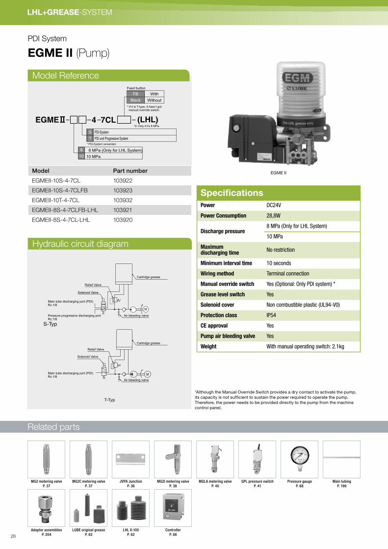
EGME II
EGME 4 7CL (LHL)*2: Only if it’s 8 MPa.
* PDI-System verwenden
S
T
PDI-System
PDI und Progressive System
8
10
8 MPa (Only for LHL System)
10 MPa
FB
Black
Feed button
With
Without
* If it is T-type, it hasn’t got manual override switch.
*Although the Manual Override Switch provides a dry contact to activate the pump,
its capacity is not sufficient to sustain the power required to operate the pump.
Therefore, the power needs to be provided directly to the pump from the machine
control panel.
Relief Valve
M
Solenoid Valve
Main tube discharging port (PDI) Rc:1/8
Pressure progressive discharging port Rc:1/8
Cartridge grease
Cartridge grease
Relief Valve
Solenoid Valve
Air bleeding valve
Air bleeding valve
Main tube discharging port (PDI) Rc:1/8
T-Typ
S-Typ
SpecificationsPower DC24V
Power Consumption 28,8W
Discharge pressure8 MPa (Only for LHL System)
10 MPa
Maximum discharging time
No restriction
Minimum interval time 10 seconds
Wiring method Terminal connection
Manual override switch Yes (Optional: Only PDI system) *
Grease level switch Yes
Solenoid cover Non combustible plastic (UL94-V0)
Protection class IP54
CE approval Yes
Pump air bleeding valve Yes
Weight With manual operating switch: 2.1kg
PDI System
EGME II (Pump)
Model Part number
EGMEII-10S-4-7CL 103922
EGMEII-10S-4-7CLFB 103923
EGMEII-10T-4-7CL 103932
EGMEII-8S-4-7CLFB-LHL 103921
EGMEII-8S-4-7CL-LHL 103920
Model Reference
Hydraulic circuit diagram
MGLA metering valve
P. 40
Controller
P. 66
Adapter assemblies
P. 204
Pressure gauge
P. 68
LHL X-100
P. 62
LUBE original grease
P. 62
MG2C metering valve
P. 37
MG2 metering valve
P. 37
MG2I metering valve
P. 38
GPL pressure switch
P. 41
Main tubing
P. 190
JVPA Junction
P. 36
26

LH
L+
GR
EA
SE
- S
YS
TE
M
80
126 218
104
24
1
25
25
27
22
25
13 3
234141
22
Air bleeding valve
Main tube discharging port (PDI) Rc:1/8Disable
Installation Hole 4ø-9
80
126 218
104
241
25
25
27
22
25
13 3
234141
22
Air bleeding valve
Main tube discharging port (PDI) Rc:1/8Progressive discharging port Rc:1/8 Disable
Installation Hole 4ø-9
EGME II-10S-4-7CLFB
EGME II-10T-4-7CL
With feed buttonWithout feed button
EGME II-S
EGME II-T
24VDCInput
Level SwitchOutput
Without feed button
GLSV
1 2 3 4 5 6
24VDCInput
Level SwitchOutput
M
GL
1 2 3 4 5 6
24VDCInput
Level SwitchOutput
GL
1 2 3 4 5 6
FB
FB
7 8
Manual Override Switch
Output
Grease level switch
Wiring diagram Grease level switch
Dimensional drawing
27

Related parts
LHL+GREASE-SYSTEM
PDI System
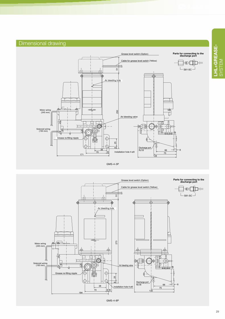
GMS (Pump)
Model Reference
Model Part Number
GMS-4-3P 103624
GMS-4-8P 103625
GMS-4L-3P 103619
GMS-4L-8P 103654
GMS-4-8PGMS-4-3P
GMS P4Reservoir typeP
Type of reservoir
DC24V4
Voltage
3
8
Reservoir capacity
Without
With
260mℓ800mℓ
Blank
L
Grease level switch
Specifications
PumpDischarge volume 20mℓ/min
Discharge pressure 8.0 MPa
Power DC24V
Motor 15W/0.65A
Pressure reliefsolenoid
30W/1.25A
Total 45W/1.9A
Maximum run time 7.5 min
Depressurization time Minimum interval time: 1 hour
Working consistencyNLGI No. 000, 00, 0 and 1 (Lithium grease)
Recommended greases
MP0, FS2
Weight 1.8kg (3P), 2.8kg (8P)
Pressure relief Built-in solenoid
Grease level switch(Option)
Contact type NC, OFF at low level
Contact capacityAC250V 2A DC30V 3A (Smaller one)
M(Red)
(White) (Blank)
(Blank)
Solenoid
(Thermal Protector)
DC24V Input
Motor
+ –
Wiring diagram
Hydraulic circuit drawing
Cap
Follower plate
Reservoir
Air bleeding button
Filling port
Relief valve
Depresserise solenoid valve
M
Hand grease gun
P. <?>
MGLA metering valve
P. 40
Controller
P. 66
Adapter assemblies
P. 204
Pressure gauge
P. 68
MG2C metering valve
P. 37
MG2 metering valve
P. 37
MG2I metering valve
P. 38
GPL pressure switch
P. 41
Main tubing
P. 190
JVPA Junction
P. 36
28
LH
L+
GR
EA
SE
- S
YS
TE
M
250
51
Discharge port
Rc1/8
Air bleeding valve
128
75
66 8
25
8
870171
38Installation hole 4-ø9
Cable for grease level switch (Yellow)
Grease level switch (Option)
Motor wiring
(345 mm)
Solenoid wiring(150 mm)
Entlüftungsöffnung Air bleeding hole
Grease re-filling nipple
130
75
66
25
8
870
184
273
51
10
38
Grease re-filling nipple
Air bleeding valve
EntlüftungsöffnungAir bleeding hole
Cable for grease level switch (Yellow)
Installation hole 4-ø98
Grease level switch (Option)
Discharge port
Rc1/8
Motor wiring
(345 mm)
Solenoid wiring(150 mm)
GMS-4-3P
GMS-4-8P
S81-SC
Parts for connecting to thedischarge port
S81-SC
Parts for connecting to thedischarge port
Dimensional drawing
29

Related parts
LHL+GREASE-SYSTEM
PDI System
EGM (Motor driven piston pump)
Model Reference
Model Part Number
EGM-10S-4-2C 103809
EGM-10S-4-4C 103810
EGM-10S-4-7C 103811
Wiring diagram
Hydraulik-Schaltplan
410SEGM CCartridge type
200 mℓ400 mℓ700 mℓ
C
Type of reservoir
2
4
7
Cartridge
EGM-10S-4-7CEGM-10S-4-4C
Specifications
PumpDischarge volume 10 mℓ/min
Discharge pressure 10 MPa
Power DC24V
Motor 20W/0.8A
Pressure reliefsolenoid
26W/1.1A
Total 46W/1.9A
Maximum run time 7.5 min.
Power distribution rate
Max. 25 % (20° C)
Working consistency NLGI No. 000,00,0,1
Recommended grease
MP0, FS2, MT1
Cartridge size 200 mℓ , 400 mℓ , 700 mℓ
Weight 1.8kg (4C), 2.8kg (7C)
Pressure relief Built-in solenoid
M(White) (Black)
DC24V Input
Motor
Solenoid
(Black)
(Thermal protector)
(White)
Cartridge
Relief valve
Solenoid
Air bleeding valve
Discharge port Rc1/8
MGLA metering valve
P. 40
Controller
P. 66
Adapter assemblies
P. 204
Pressure gauge
P. 68
LHL X-100
P. 62
LUBE original grease
P. 62
MG2C metering valve
P. 37
MG2 metering valve
P. 37
MG2I metering valve
P. 38
GPL pressure switch
P. 41
Main tubing
P. 190
JVPA Junction
P. 36
30

LH
L+
GR
EA
SE
- S
YS
TE
M
25
1
25
10
9
141
Motor wiring
(L=300)
Solenoid wiring(L=230)
179
104 16
59
25
(Sticker)
(Sticker)
4-ø9 Installation hole
Air bleedingvalve
Discharge port Rc1/8
400
109
25
25
59
(127)176
104 13
Air bleeding valve
Installation hole 4-ø9
Discharge port Rc1/8
222 2
5
127
104
176
59
25
109
4-ø9 Installationhole
Air bleedingvalve
Discharge port Rc1/8
(Sticker)
EGM-10S-4-4C
EGM-10S-4-2C EGM-10S-4-7C
S81-SC
Parts for connecting to thedischarge port
S81-SC
Parts for connecting to thedischarge port
S81-SC
Parts for connecting to thedischarge port
Dimensional drawing
31

Related parts
LHL+GREASE-SYSTEM
PDI System
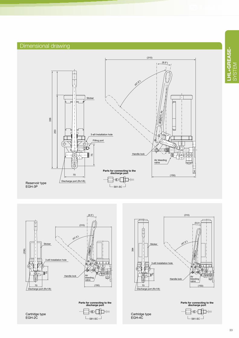
EGH (Manually operated pump)
Model Reference
Model Part Number
EGH-2C 103780
EGH-3P 103783
EGH-4C 103782
Hydraulic circuit drawing
EGH
Reservoir type (260 mℓ)
Cartridge type (200 mℓ)
Cartridge type (400 mℓ)
3P
2C
4C
Type of reservoir (effective capacity)
Reservoir or cartridge grease
Refilling port Relief valve
Manual depressurizing valve
Air bleeding valve
Discharge Port
Adapter assemblies
P. 204
Main tubing
P. 190
Pressure gauge
P. 68
LUBE original grease
P. 62
MG2C metering valve
P. 37
MG2 metering valve
P. 37
MG2I metering valve
P. 38
JVPA Junction
P. 36
SpecificationsEGH-3P
Pump Discharge volume 1 mℓ/stroke
Discharge pressure
10 MPa (safety valve set pressure)
Working consistency NLGI No. 000, 00, 0, 1 (lithium grease)
Recommended grease MP0, FS2, MT1
Reservoir Size 260 mℓ
Weight 1.4 kg
Pressure relief Manual pressure relief lever
EGH-2C / EGH-4C
Pump Discharge volume 1 mℓ/stroke
Max Dischargepressure
10 MPa (safety valve set pressure)
Working consistency Cartridge grease No.000, 00, 0, 1(lithium grease)
Recommended grease MP0, FS2, MT1
Cartridge size 200 mℓ, 400 mℓ Cartridge
Weight 1.4 kg
Pressure relief Manual pressure relief lever
EGH-3P EGH-2C EGH-4C
32
LH
L+
GR
EA
SE
- S
YS
TE
M
Sticker
Discharge port (Rc1/8)
Filling port
3-ø9 Installation hole
Air bleedingvalve
(9.5°)
(150)
9
336
253
75
70
(310)
(47.5
°)
Handle lock
70
75
(33
6)
(310)
(47.5 )
(150)
(9.5 )
Sticker
3-ø9 Installation hole
Airbleedingvalve
Handle lock
Discharge port (Rc1/8)
Reservoir typeEGH-3P
Cartridge typeEGH-2C
70
75
39
4
Sticker
3-ø9 Installation hole
Airbleedingvalve
Handle lock
Discharge port (Rc1/8)
(310)
(150)
(9.5°)
(47.5°)
Cartridge type EGH-4C
S81-SC
Parts for connecting to thedischarge port
S81-SC
Parts for connecting to thedischarge port
S81-SC
Parts for connecting to thedischarge port
Dimensional drawing
33

Related parts
LHL+GREASE-SYSTEM
PDI System
GAS (Pneumatic grease pump)
Model Part Number
GAS-8P 102621
Dimensional drawing
GAS-8P
Specifications
Pump
Dischargevolume
16mℓ/Stroke (MAX)
Dischargepressure
1:7 Air pressure / Greasepressure ratio. (E.g. : Airpressure 0.3 MPa ×7 = 2.1 MPa)
Available airpressure range
0.3 - 0.56 MPa (MAX)
Working consistency NLGI No.000, 00, 0 and 1 (Lithium grease)
Recommended grease MP0, FS2
Grease level switch Optional
Reservoir capacity 800 mℓ
Weight 3.6 kg
Pressure relief Automatic
140
853.2 110
54
Air input25
9
260
Rc1/8
Discharge port Rc1/8
Air bleeding valve
Installation hole
Grease re-filling nipple
4-ø9
Hydraulic circuit drawingPump installation
Tank lid
Follower plate
Tank
Grease re-filling nipple
Three-way solenoid valve
Pressure reducing valve
Air input
Automaticdepressurization valve
Air bleeding valve
Three-way solenoid valve
P. 78
Filter regulator
P. 78
Hand grease gun
P. <?>
GPL pressure switch
P. 41
Adapter assemblies
P. 204
Main tubing
P. 190
Pressure gauge
P. 68
MG2C metering valve
P. 37
MG2 metering valve
P. 37
MG2I metering valve
P. 38
JVPA Junction
P. 36
34

LH
L+
GR
EA
SE
- S
YS
TE
M
JV (Junction)
JV-6S
Dimensional drawing
20.5
8
2-Rc1/8
29
ø16
ø7
ø118
2-Rc18
33
ø16
8
20.5
ø7
3-Rc1/8
16.5
24.5
35 10.5
ø74-Rc1/8
33
11
15
20
ø11
35 10.5
16 16
16
20
2-ø78-RC
18/
L2
L1
ø11
Model Part No. Specifications L1 L2
JV-4S 206472 Single type for 2 ports 49 38
JV-5S 206473 Single type for 3 ports 65 54
JV-6S 206474 Single type for 4 ports 81 70
JV-7S 206475 Single type for 5 ports 97 86
JV-8S 206476 Single type for 6 ports 113 102
JV-9S 206479 Single type for 7 ports 129 118
JV-10S 206543 Single type for 8 ports 145 134
Material: Zinc Die-casting (ZDC)
Model Part No. Specifications
JV-3 206471 Single type for 1 port
Material: Zinc Die-casting (ZDC)
Model Part Number
JV-2 206470
Material: Zinc Die-casting (ZDC)
Model Part No. Specifications
JV-4D 206464 Double type for 2 ports
Material: Brass (C3604)
Model Part No. Specifications L1 L2
JV-6D 206465 Double type for 4 ports 49 38
JV-8D 206466 Double type for 6 ports 65 54
JV-10D 206467 Double type for 8 ports 81 70
JV-12D 206468 Double type for 10 ports 97 86
JV-14D 206469 Double type for 12 ports 113 102
Material: Brass (C3604)
20.5
8
4-Rc1/8
10.5
16
ø11
16.5
ø16
2-ø7
L2
L1
JV-4S
JV-8D
35

LHL+GREASE-SYSTEM
PDI System
JVPA (Junctions and special fittings for MO2 series valve installation)
Dimensional drawing
Model Part Number
SCP 619803
Material: Brass (C3604)
Model Part Number
BPP 619802
Material: Steel (SUM24)
M12×1
O-ring
Rc1/8
24HEX12
M12×1
O-ring5 14
Plug assembly
Connector assembly
12-M12×1
L2
L1
L2
L1
2-φ7
16 16
16
16 16 16
2-M12×1
2-φ7
10.5
17.5
7
202-Rc1/8
11
35
15
20
2-Rc1/8
Clamp face
Clamp face
11
25
15
Junction JVPA-12D
Junction JVPA-2S
Model Part No. Specification L1 L2
JVPA- 1S 216001 Single type for 1 port 33 22
JVPA- 2S 216002 Single type for 2 ports 49 38
JVPA- 3S 216003 Single type for 3 ports 65 54
JVPA- 4S 216004 Single type for 4 ports 81 70
JVPA- 5S 216005 Single type for 5 ports 97 86
JVPA- 6S 216006 Single type for 6 ports 113 102
JVPA- 7S 216007 Single type for 7 ports 129 118
JVPA- 8S 216008 Single type for 8 ports 145 134
JVPA- 9S 216009 Single type for 9 ports 161 150
JVPA-10S 216010 Single type for 10 ports 177 166
JVPA-11S 216011 Single type for 11 ports 193 182
JVPA-12S 216012 Single type for 12 ports 209 198
Model Part No. Specification L1 L2
JVPA- 2D 216021 Double type for 2 ports 33 11
JVPA- 4D 216022 Double type for 4 ports 49 38
JVPA- 6D 216023 Double type for 6 ports 65 54
JVPA- 8D 216024 Double type for 8 ports 81 70
JVPA-10D 216025 Double type for 10 ports 97 86
JVPA-12D 216026 Double type for 12 ports 113 102
JVPA-14D 216027 Double type for 14 ports 129 118
JVPA-16D 216028 Double type for 16 ports 145 134
Material: Aluminium (A6063S-T5)
36

LH
L+
GR
EA
SE
- S
YS
TE
M
Related parts
MG2 · MG2C (Metering valve)
* MG2C for use with nylon tubing only
** Production lot is indicated by a number and letter code.
Number indicates year of production, letter indicates
month of production. [A(January)-L(December)]
SpecificationsOperating pressure 2.5 MPa
Reset pressure 1.4 MPa
MG2 · MG2C
Grooving
Model Part No.Discharge
volume (mℓ)L (mm) Mark
MG2-3 205741 0.03
48
3
HEX12
MG2-5 205742 0.05 5
MG2-10 205743 0.1 10
MG2-20 205744 0.2
64
20
MG2-30 205745 0.3 30
MG2-50 205746 0.5 50
MG2C-3 205731 0.03
53.5
3
MG2C-5 205732 0.05 5
MG2C-10 205733 0.1 10
MG2C-20 205734 0.2
69.5
20
MG2C-30 205735 0.3 30
MG2C-50 205736 0.5 50
Dimensional drawing
M12×1
ø4 Nylon tubing
LH
EX
12
□10
5 3
A
M12×1
O-ringO-ring
M8×1 (ø4 tubing)
LH
EX
12
□10
50
3A
Dischargevolume
Dischargevolume
Productionlot
Productionlot
MG2 MG2C
Operation chart
Start of pum
p operation
Start of pressure rise
Va
lve
op
en
s
Pressure starts rising beforedischarge of grease
1. Before the discharge
(Start of pressure rise)
2. Pump pressurizing
Completion of discharge (under pressure)
3. Measuring
(piston returning)
Valve begins toDischarge dischargeDischarge
O-ringCollar
A
Check valve
Inner pressure relieves
Depressed
Pump operation Pump stops
Pum
p re
lief o
pens
Pu
mp
sto
ps
Inner pressure relieves
Return of valve piston
Fin
ish
O-ring and collar go up
and push up the grease
(oil) in the measuring
chamber.
Spring starts
pushing down
O-ring and collar.
In the meantime,
the path (A) opens
up and the tip of
the check valve
seals the path from
the junction.
Grease (oil) refills
the measuring
chamber.
KEN-T
P. 201
KEN-M
P. 201
Adapters
P. 194
Compression parts
P. 188
Branch tubing
P. 190
GMS-4-8P
P. 28
EGM-T-10S-4-7C
P. 36
EGH 3P
P. 38
EGH 2C
P. 38
GAS
P. 34
Adapter assemblies
P. 204
Main tubing
P. 190
Pressure gauge
P. 68
37

Related parts
LHL+GREASE-SYSTEM
PDI System
MG2I (Metering valve with clogged line detection)
* MG2C for use with nylon tubing only
** Production lot is indicated by a num-
ber and letter code. Number indicates
year of production, letter indicates
month of production.
[A(January)-L(December)]
MG2I-30 MG2I-10
Dimensional drawing
M8 × 1 (ø4 Tubing)
HE
X12
L
10 4
A
(5)40
Detection pin
Discharge volume
Lot
M12×1
O-ring
SpecificationsOperating pressure 1.5 MPa
Reset pressure 0.5 MPa
Detection pin operating pressure 1.5 MPa
Model Part No. Discharge
volume (mℓ)
L (mm) Mark
MG2I-5 205822 0.05 70 5
MG2I-10 205823 0.1 70 10
MG2I-20 205824 0.2 86 20
MG2I-30 205825 0.3 86 30
MG2I-50 205826 0.5 86 50
GMS-4-8P
P. 28
EGM-T-10S-4-7C
P. 36
EGH 3P
P. 38
EGH 2C
P. 38
GAS
P. 34
KEN-T
P. 201
KEN-M
P. 201
Branch tubing
P. 190
Main tubing
P. 190
Adapters
P. 194
Compression parts
P. 188
Adapter assemblies
P. 204
Pressure gauge
P. 68
JVPA junction
P. 36
38

LH
L+
FE
TT-
SY
STE
ME
Piping layout (Example)
A
JVPA Junction
EA4-20Elbow adapter
KEN-MDischarge confirmation pin
SA4-16Straight adapter
CB-4-8Bushing
TI-4Tube insert
CS-4Sleeve
NT-4ø4 Nylon tube
ST-4Zø4 Copper piping
BP-1Blanking plug
S81-SCConnectors: Straight
ST-8ZMain tubing ø8
KEN-T Indicator pin
B
T
T
T
MG2I valve
Use an appropriate sealant where mark is shown.
Mark denote tightening torque. See the tightening torque list P.234.
39

Related parts
LHL+GREASE-SYSTEM
GAS
P. 38
PDI System
MGLA (Metering valve with electronic performance monitoring)
MGLA
Dimensional drawing
Wiring diagram
SpecificationsDischarge volume 0.1, 0.2, 0.3, 0.5mℓ/stroke
Operating pressure 2.5 MPa
Reset pressure 1.2 MPa
Contact capacity AC125V 2A AC250V 2A DC30V 2A
Material: Zinc Die Casting (ZDC)
COM
Black
NO
White
NC
Red
Contact type
(290)
122
58.5
11.5
34.5
30
252-Rc1/8
DischargeportRc1/8
Mark
18
Model Part No. Discharge volume (mℓ) Mark
MGLA-10 205515 0.1 10
MGLA-20 205518 0.2 20
MGLA-30 205588 0.3 30
MGLA-50 205589 0.5 50
MGLA
GMS-4-8P
P. 28
EGM-T-10S-4-7C
P. 36
EGH 3P
P. 38
EGH 2C
P. 38
KEN-T
P. 201
KEN-M
P. 201
Branch tubing
P. 190
Main tubing
P. 190
Adapters
P. 194
Compression parts
P. 188
Adapter assemblies
P. 204
Pressure gauge
P. 68
JVPA Junction
P. 36
40

LH
L+
GR
EA
SE
- S
YS
TE
M
EGH 3P
P. 38
GPL (Pressure switch)
Related parts
GPL-30 GPL-30-D
Dimensional drawing
Wiring diagram
Model Part Number
GPL-30 209282
GPL-30-D 209409
GPL-55 209392
GPL-55-D 209403P R E S S U R E S W I T C H
MODEL
OPERATION PRESSURE
CONTACT CAPACITY
CODE NO.
GPL-55-D
5.5MPa
DC24V 0.1A
209403
85
26
32
22
7.5
2-Rc1/8
9
12.5
23.5
33.5
55 2K
Typ
Production
lot
Nameplate Wiring diagram
Wire opening
Applicable cable diameter
ø4.5-6
DIN terminal connection diagram
3.COM (Black)
1.NC (Red)
1
3 2
2.NO (White)
1 2
3
Specifications (GPL-30)Operating pressure 3.0 MPa ± 20 %
Reset pressure 2.5 MPa ± 20 %
Max. working pressure 10 MPa
Microswitchspec
Rated voltage AC250V, DC30V, DC24V (only "D")
Resistance load 2A (AC250V, DC30V)
Service life 200,000 switchings (loaded)
Structuralprotection
JIS moisture-tight, conforming to IEC IP67
Specifications (GPL-55)Operating pressure 5.5 MPa ± 0.4 MPa
Microswitchspec
Rated voltage AC250V, DC30V, DC24V (only "D")
Resistance load 2A(AC250V, DC30V)
Service life 200,000 switchings (loaded)
Structural protection
JIS moisture-tight, conforming to IEC IP67
COM
Black
NO
White
NC
Red
Contact type
Material: Aluminium-Druckguss (ADC)
(290)
(10)
85.5
26
552-Rc1/8
32
9
22
7.5
12.5
23.5
30.5
5
7A
Typ
Production
lot
GPL-55-D
* Production lot is indicated by a number and letter code. Number indicates year of production, letter indicates month of production. [A(January)-L(December)]
GPL-55
GMS-4-8P
P. 28
EGM-T-10S-4-7C
P. 36
EGH 3P
P. 38
EGH 2C
P. 38
KEN-T
P. 201
KEN-M
P. 201
Branch tubing
P. 190
Main tubing
P. 190
Adapters
P. 194
Compression parts
P. 188
Adapter assemblies
P. 204
Pressure gauge
P. 68
JVPA Junction
P. 36
41

42

System-Layouts P. 44
PumpsYMT P. 46
GMN P. 48
GMNH P. 50
EGH P. 52
EGM-T P. 54
EGME-T P. 56
ValvesSP P. 58
➔ PROGRESSIVE
43

LHL+GREASE-SYSTEM
Linear guide Ball screw
Pillow block
Wiring
GMNH-4-4CP. 56
Controller (without YMT)
P. 93
Elbow adapterP. 196
SP series progressive valve SP-8KP. 64
Fitting for limited placeP. 202 Straight adapter
P. 194
Compression sleeveP. 188
Flexible hoseP. 192
SP series progressive valve SP-8K P. 64
Tube insertP. 188
Compression bushingP. 188
YMTP. 52
EGH-2CP. 58
Signal
EGH-3PP. 58
EGH-4C P. 52
GMNH-2-4CP. 56
GMNH-2-7CP. 56
GMNH-4-7C P. 50
GMN-4-8P P. 48
Tubing P. 190
Adapter assembliesP. 204
Progressive System for Small-Large machines
Layouts
44
LH
L+
GR
EA
SE
- S
YS
TE
M
GearCam
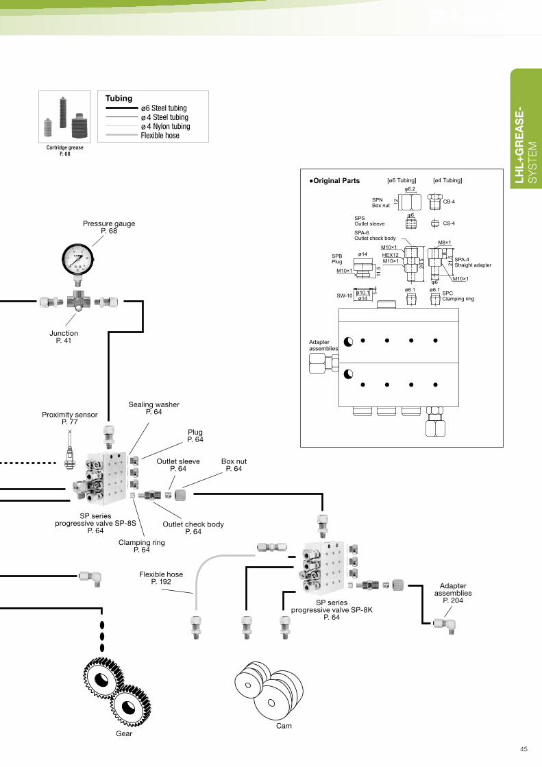
●Original Parts
Adapterassemblies
ø6.1 ø6.1
HEX12
M8×1
26.5
φ6
21
.58
M10×1
11
.5
ø14
M10×1
M10×1
M10×1
12
φ6.2
ø10.1ø14
1
SPSOutlet sleeve
SPCClamping ring
SPBPlug
SPNBox nut
[ø6 Tubing] [ø4 Tubing]
SW-10
SPA-4Straight adapter
CB-4
CS-4
SPA-6Outlet check body
φ6
Schmierfett
S. 89
φ 6 Stahlrohrleitung
φ 4 Stahlrohrleitung
φ 4 Nylon-Schlauch
Flexibler Schlauch
Leitungen
Adapter assemblies
P. 204SP seriesprogressive valve SP-8K
P. 64
Flexible hoseP. 192
Clamping ringP. 64
SP seriesprogressive valve SP-8S
P. 64Outlet check body
P. 64
Box nutP. 64
PlugP. 64
Sealing washerP. 64Proximity sensor
P. 77
JunctionP. 41
Pressure gauge P. 68
Outlet sleeve P. 64
Cartridge grease
P. 68
ø6 Steel tubing ø 4 Steel tubing ø 4 Nylon tubing Flexible hose
Tubing
45
Related parts
LHL+GREASE-SYSTEM
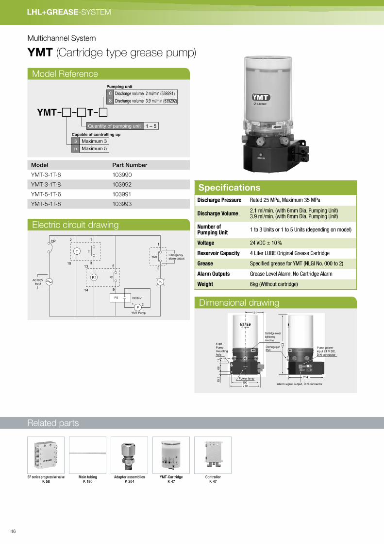
Multichannel System
YMT (Cartridge type grease pump)
Electric circuit drawing
Model Reference
YMT T
6
8
Pumping unit
Capable of controlling up
3
5
Maximum 3
Maximum 5
Discharge volume 2 ml/min (539291)
Discharge volume 3.9 ml/min (539292)
Quantity of pumping unit 1 – 5
Model Part Number
YMT-3-1T-6 103990
YMT-3-1T-8 103992
YMT-5-1T-6 103991
YMT-5-1T-8 103993
Dimensional drawing
CP
T T
1
1
2
2
31013
14
5
9
R1 R1AC100V
InputPL
P
1 2
DC24VPS
YMTEmergency
alarm output
YMT Pump
SpecificationsDischarge Pressure Rated 25 MPa, Maximum 35 MPa
Discharge Volume2.1 ml/min. (with 6mm Dia. Pumping Unit)3.9 ml/min. (with 8mm Dia. Pumping Unit)
Number of Pumping Unit
1 to 3 Units or 1 to 5 Units (depending on model)
Voltage 24 VDC ± 10 %
Reservoir Capacity 4 Liter LUBE Original Grease Cartridge
Grease Specified grease for YMT (NLGI No. 000 to 2)
Alarm Outputs Grease Level Alarm, No Cartridge Alarm
Weight 6kg (Without cartridge)
12
66
15.9 Power lamp
Pump
mounting
hole
Discharge portPS/4
Alarm signal output, DIN connector
423
264
190
131
210
Pump power
input 24 V DC,
DIN connector
Cartridge cover
tightening
direction
Adapter assemblies
P. 204
SP series progressive valve
P. 58
YMT-Cartridge
P. 47
Controller
P. 47
Main tubing
P. 190
46

LH
L+
GR
EA
SE
- S
YS
TE
M
Specified LUBE Original Grease
Lube offers ferrography analysis to check lubrication conditions.
* Free of charge for the first analysis.
Pressure Gauge
Steel Tubing
24VDC
(Controller)
Capable of controlling up to 5 lines.
Series Progressive Valve (with the performance indicator pin) Model SP
Newly Developed Grease Pump : Model YMT
MP2
High-performance General
Purpose Grease for
Industrial Machines.
Lithium-based grease for general industrial machines with
extreme pressure properteis and a wide range of applications.
YM2
High Load and High
Pressure Grease
Grease containing organic molybdenum with excellent heavy load
carrying capacity, abrasion resistance and seizure resistance.
Pump ControllerSpecificationsInput Voltage AC 100 V, AC 200 V 50 / 60 Hz
Discharge Volume Control Timer or Count
Discharge Time 1 to 99 minutes (1-minute increments)
Number of Count 1 to 99 counts (1-count increments)
Interval 1 to 99 hours (1-hour increments)
Alarm Detection - Grease Level- No Cartridge- Pressure Alarm- Valve Malfunction (Count Mode only)
Alarm Signal Output Rated Load: 200V 2A or less
Input Signal Proximity Switch Number of Signal Input: 1 to 5
Protection Class and Standards
CE (Applied), IP65
Mounting Hole
M5 x 4
Alarm Signal Input
Pump Power Output 24 VDC
Proximity Switch Input
Input Voltage
100 VAC to 200 VAC
Model Part Number
YMT-C-E-S-AC 300421
115
90
118.4
40 37.5
55
25
Terminal box
Model Part Number
YMT-TBOX 300423
47

Related parts
LHL+GREASE-SYSTEM
Progressive System
GMN (Motorized grease pump)
GMN-4-8P
Model Reference
SpecificationsGMN-4-8P
Discharge volume 20 mℓ/min
Discharge pressure 8 MPa (Safety valve set pressure)
Working consistency NLGI No.000, 00, 0 and 1 (Lithium grease)
Recommended grease MP0 and FS2
Motor
Working voltage/Working current
DC24V/1A
Output 15 W DC Brush motor
Grease level switch Optional
Reservoir capacity 800 mℓ
Weight 2.8 kg
GMN P84
DC24V4
Working voltage
Re-filling type 800 mℓ8P
Tank model (capacity)
Model Part Number
GMN-4-8P 102909
Main tubing
P. 190
Adapter assemblies
P. 204
SP series progressive valve
P. 58
Controller
P. 66
Netzanschlusskasten Hand grease gun
P. <?>
Lub pack
P. <?>
Pressure gauge
P. 68
48

LH
L+
GR
EA
SE
- S
YS
TE
M
Dimensional drawing
Hydraulic circuit drawing
182
70
130
8
229
25
Grease re-filling nipple
Air bleeding valve
3-ø9
Installation hole(Rc1/8)
Discharge port
Cable formotor
(345)
GMN-4-8P
S81-SC
Parts for connecting to thedischarge port
Reservoir lid
Follower plate
Grease re-filling nipple
Reservoir
M
Relief valve
Air bleeding valve
49
Related parts
LHL+GREASE-SYSTEM
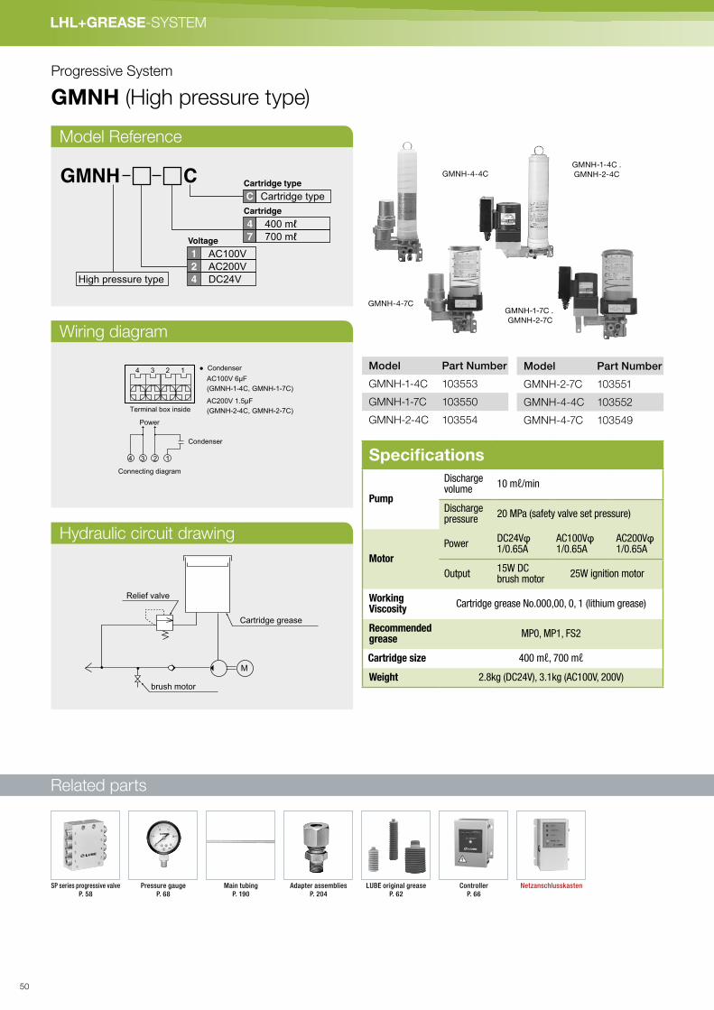
Progressive System
GMNH (High pressure type)
Model Reference
Wiring diagram
Hydraulic circuit drawing
● Condenser4 3 2 1
4 3 2 1
Condenser
Connecting diagram
Terminal box inside
Power
AC100V 6μF
(GMNH-1-4C, GMNH-1-7C)
AC200V 1.5μF
(GMNH-2-4C, GMNH-2-7C)
Cartridge grease
M
Relief valve
brush motor
GMNH CCartridge typeC
Cartridge type
400 mℓ
700 mℓ
4
7
AC100V
AC200V
DC24V
1
2
4High pressure type
Cartridge
Voltage
Specifications
Pump
Dischargevolume
10 mℓ/min
Dischargepressure
20 MPa (safety valve set pressure)
Motor
PowerDC24Vφ 1/0.65A
AC100Vφ 1/0.65A
AC200Vφ 1/0.65A
Output15W DC brush motor
25W ignition motor
WorkingViscosity
Cartridge grease No.000,00, 0, 1 (lithium grease)
Recommendedgrease
MP0, MP1, FS2
Cartridge size 400 mℓ, 700 mℓ
Weight 2.8kg (DC24V), 3.1kg (AC100V, 200V)
Model Part Number
GMNH-2-7C 103551
GMNH-4-4C 103552
GMNH-4-7C 103549
Model Part Number
GMNH-1-4C 103553
GMNH-1-7C 103550
GMNH-2-4C 103554
GMNH-4-7CGMNH-1-7C .
GMNH-2-7C
GMNH-4-4CGMNH-1-4C .
GMNH-2-4C
SP series progressive valve
P. 58
Controller
P. 66
LUBE original grease
P. 62
Pressure gauge
P. 68
Netzanschlusskasten Main tubing
P. 190
Adapter assemblies
P. 204
50

LH
L+
GR
EA
SE
- S
YS
TE
M
Dimensional drawing
(t=3.2)
21
100 70 8
82
5
(239)
128 8
39
1
25
0
Air bleeding
valve
Installation
hole 5-ø9
Discharge
port Rc1/8
Space for cartridge
replacement
Air bleeding valve
70 75
128171
8 8
825
391
Installation
hole
4-ø9
250 Space for cartridge
replacement
DischargeportRc1/8
Cable formotor
(345)
31
02
58
(20.5)70
197
875
133.5
Air bleeding
valve
Installation
hole
4-ø9
Discharge
port Rc1/8
230
Cable formotor
(345)
Space for
cartridge
replacement
Discharge port Rc1/8
310
230
(t=3.2)
23100 70 (23)
257
825
133.5
758
Air bleeding
valve
Installation
hole
5-ø9
Discharge
port Rc1/8
Discharge port Rc1/8
Space for
cartridge
replacement
GMNH-4-7C GMNH-1-7C . GMNH-2-7C
GMNH-4-4C GMNH-2-4C . GMNH-1-4C
S81-SC
Parts for connecting to thedischarge port
S81-SC
Parts for connecting to thedischarge port
S81-SC
Parts for connecting to thedischarge port
S81-SC
Parts for connecting to thedischarge port
51

Related parts
LHL+GREASE-SYSTEM
Progressive System
EGH (Manual grease pump)
Model Reference
Hydraulic circuit drawing
EGH-3P EGH-2C EGH-4C
EGH
Reservoir type (260 mℓ)
Cartridge type (200 mℓ)
Cartridge type (400 mℓ)
3P
2C
4C
Type of reservoir
Cover
Follow plate
Reservoir or cartridge grease
Refilling portRelief valve
Manual depressurized valveManual depressurization valve
Air bleeding valve
SpecificationsEGH-3P
Pump
Discharge volume 1 mℓ/stroke
Discharge pressure
10 MPa (safety valve set pressure)
Working Viscosity NLGI No. 000, 00, 0, 1 (lithium grease)
Recommended grease MP0, FS2, MT1
Reservoir Capacity size 260 mℓ
Weight 1.4 kg
Pressure relief Manual pressure relief lever
EGH-2C EGH-4C
Pump
Discharge volume 1 mℓ/stroke
Discharge pressure
10 MPa (safety valve set pressure)
Working viscosityCartridge grease No.000, 00, 0, 1 (lithium grease)
Recommended grease MP0, FS2, MT1
Cartridge size 200mℓ, 400mℓ Cartridge
Weight 1.4 kg
Pressure relief Manual pressure relief lever
Model Part Number
EGH-2C 103780
EGH-3P 103783
EGH-4C 103782
LUBE original grease
P. 62
Main tubing
P. 190
SP series progressive valve
P. 58
Pressure gauge
P. 68
Adapter assemblies
P. 204
52

LH
L+
GR
EA
SE
- S
YS
TE
M
Dimensional drawing
Sticker
Discharge port (Rc1/8)
Filling port
3-ø9 (Installation hole)
Air bleeding
valve
(150)
9
33
6
25
3
75
70
(310)
Handle lock
(9.5°)
(47.5
°)
Reservoir type
EGH-3P
S81-SC
Parts for connecting to thedischarge port
(47.5°)
70
75
39
4
Sticker
Discharge port (Rc1/8)
3-ø9 (Installation hole)
Airbleedingvalve
Handle lock
(310)
(150)
(9.5°)
70
75
(33
6)
(310)
(150)
Sticker
Discharge port (Rc1/8)
3-ø9 (Installation hole)
Airbleedingvalve
Handle lock
(9.5°)
(47.5°)
Cartridge type
EGH-2C
Cartridge type
EGH-4C
S81-SC
Parts for connecting to thedischarge port
S81-SC
Parts for connecting to thedischarge port
53
Related parts
LHL+GREASE-SYSTEM
Progressive System
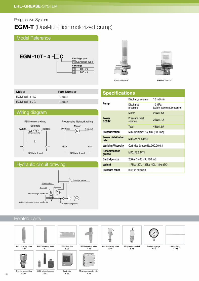
EGM-T (Dual-function motorized pump)
Model Reference
Wiring diagram
Hydraulic circuit drawing
EGM-10T-4-4C EGM-10T-4-7C
DC24V Input
Solenoid
PDI Network wiring Progressive Network wiring
(White) (Black)
(Thermoschutz)M
(White) (Black)
DC24V Input
Motor
Air bleeding valve
Relief valve
Cartridge grease
M
Solenoid
PDI discharge port Rc 1/8
Series progressive system port Rc 1/8
4EGM 10T CCartridge typeC
Cartridge type
400 mℓ700 mℓ
4
7
Cartridge
Specifications
Pump
Discharge volume 10 mℓ/min
Dischargepressure
10 MPa (safety valve set pressure)
PowerDC24V
Motor 20W/0.8A
Pressure reliefsolenoid
26W/1.1A
Total 46W/1.9A
Pressurization Max. ON time: 7.5 min. (PDI Port)
Power distributionrate
Max. 25 % (20°C)
Working Viscosity Cartridge Grease No.000,00,0,1
Recommendedgrease
MP0, FS2, MT1
Cartridge size 200 mℓ, 400 mℓ, 700 mℓ
Weight 1.78kg (2C), 1.83kg (4C), 1.8kg (7C)
Pressure relief Built-in solenoid
Model Part Number
EGM-10T-4-4C 103834
EGM-10T-4-7C 103835
Main tubing
P. 190
Adapter assemblies
P. 204
SP series progressive valve
P. 58
Controller
P. 66
LUBE original grease
P. 62
MGLA metering valve
P. 40
Pressure gauge
P. 68
GPL pressure switch
P. 41
MG2I metering valve
P. 38
MG2C metering valve
P. 37
MG2 metering valve
P. 37
JVPA Junction
P. 36
54
LH
L+
GR
EA
SE
- S
YS
TE
M
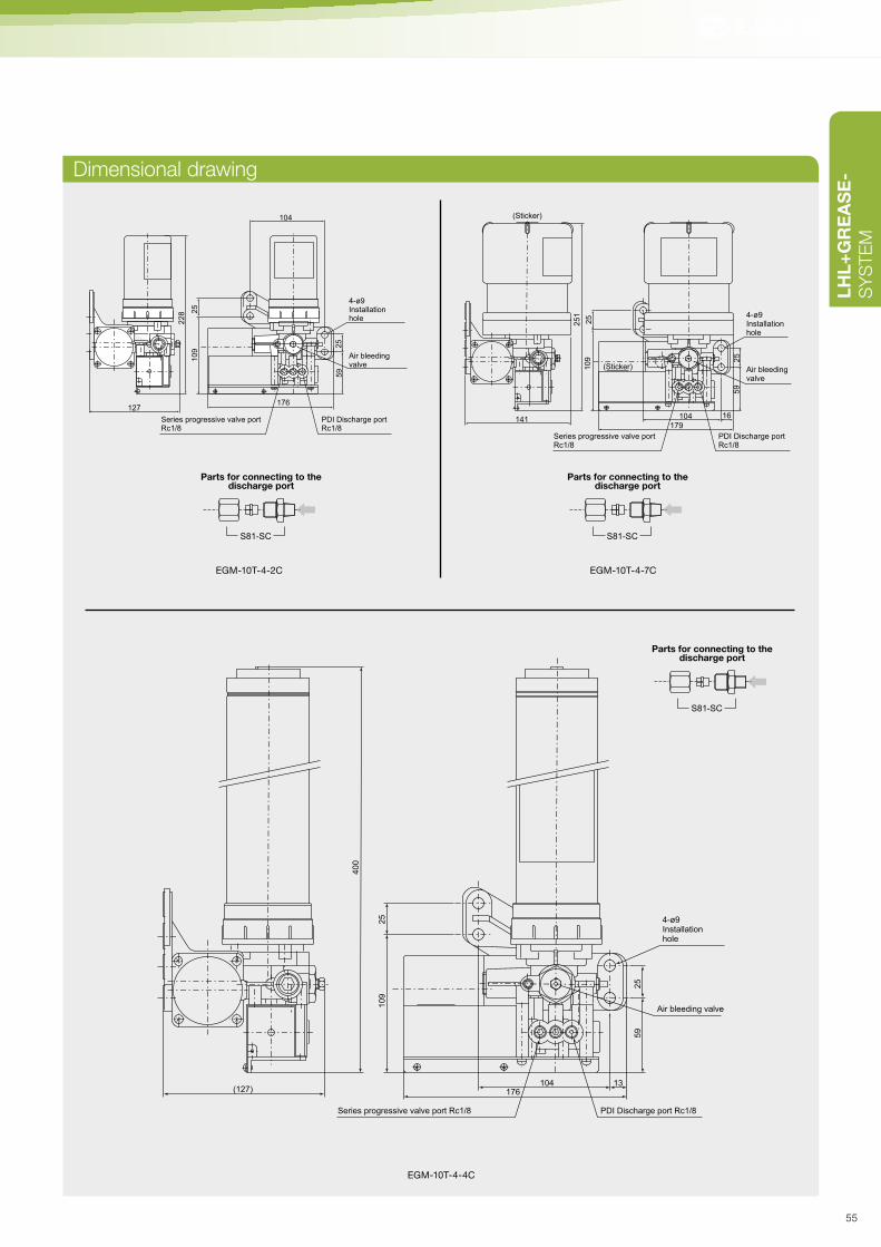
Dimensional drawing228 2
5
127
104
176
59
25
10
9
4-ø9 Installation hole
Air bleeding valve
PDI Discharge port Rc1/8
Series progressive valve port Rc1/8
EGM-10T-4-2C
S81-SC
Parts for connecting to thedischarge port
(Sticker)
(Sticker)
25
1
25
109
141179
104 16
59
25
4-ø9 Installation hole
Air bleeding valve
PDI Discharge port Rc1/8
Series progressive valve port Rc1/8
EGM-10T-4-7C
S81-SC
Parts for connecting to thedischarge port
40
0
10
92
5
25
59
(127) 176104 13
4-ø9 Installationhole
Air bleeding valve
PDI Discharge port Rc1/8Series progressive valve port Rc1/8
S81-SC
Parts for connecting to thedischarge port
EGM-10T-4-4C
55

Related parts
LHL+GREASE-SYSTEM
Progressive System
EGME-T (Dual-function motorized pump)
Model Reference
Wiring diagram
Hydraulic circuit drawing
EGME-10T-4-2C
Model Part Number
EGME-10T-4-2C 103902
EGME-10T-4-7C 103911
Specifications
Pump
Discharge volume 10 mℓ/min
Discharge pressure10 MPa (safety valve set pressure)
PowerDC24V
Motor 20W/0.8A
Pressure relief solenoid
10W/0.4A
Total 30W/1.2A
Working Viscosity Cartridge Grease No. 000,00,0,1
Recommendedgrease
MP0, FS2, MT1
Cartridge size 200 mℓ, 400 mℓ, 700 mℓ
Weight 1.8kg (4C), 2.8kg (7C)
Pressure relief Built-in solenoid
1 2 3 4
DC24V Input
(+) (+)-
Terminal box
Motor Solenoid
4EGME 10T CCartridge typeC
Cartridge type
200 mℓ
400 mℓ
700 mℓ
2
4
7
Cartridge
Air bleeding valve
Relief valve
Cartridge grease
M
Solenoid
PDI discharge port Rc 1/8
Series progressive system port Rc 1/8
Main tubing
P. 190
Adapter assemblies
P. 204
SP series progressive valve
P. 58
Controller
P. 66
LUBE original grease
P. 62
MGLA metering valve
P. 40
Pressure gauge
P. 68
GPL pressure switch
P. 41
MG2I metering valve
P. 38
MG2C metering valve
P. 37
MG2 metering valve
P. 37
JVPA Junction
P. 36
56

LH
L+
GR
EA
SE
- S
YS
TE
M
Dimensional drawing
EGME-10T-4-2C EGME-10T-4-7C
EGME-10T-4-4C
22
8
127
87
213104
59
70
25
25
25
27
4-ø9 Installation hole
Air bleeding valve
PDI Discharge port Rc1/8Series progressive valve port Rc1/8
Wiring port
ø21
13
S81-SC
Parts for connecting to thedischarge port
22
8
127
87
213104
59
70
25
25
25
27
ø21
13
(Sticker)
4-ø9 Installation hole
Air bleeding valve
PDI Discharge port Rc1/8Series progressive valve port Rc1/8
Wiring port
S81-SC
Parts for connecting to thedischarge port
40
0
127
87
213
104
59
70
25
25
25
27
ø21
13
4-ø9 Installation hole
Air bleeding valve
PDI Discharge port Rc1/8 Series progressive valve port Rc1/8Wiring port
S81-SC
Parts for connecting to thedischarge port
57

Related parts
LHL+GREASE-SYSTEM
Progressive System
SP (Valve)
Model Reference
SP-8
EGH
Reservoir type (260 mℓ)
Cartridge type (200 mℓ)
Cartridge type (400 mℓ)
3P
2C
4C
Type of reservoir
S: With proximity sensor adaptor
K: With indicator pin
*L: See dimensional drawing
Model Part Number
SPB 611785
SW-10 207611
SPC 611677
SPA-6 619780
SPS 611695
SPN 611784
SPA-4 166005
SpecificationsDischarge volume 0.2 mℓ/stroke
Discharge port 6 mm or 4 mm tube
Grease inlet Rc1/8
Max. working pressure 20 MPa
Minimum operating pressure 2 MPa
Working consistency NLGI No. 000-2
Performance monitor Indicator pin (K type)
Material SP: Aluminum
Model Part No.No. of
discharge portsLength (L)
SP-4K 2055304
60
SP-4 205540
SP-6K 205531
6SP-6 205541
SP-6S 205536
SP-8K 205532
8 75SP-8 205542
SP-8S 205537
SP-10K 205533
10 90SP-10 205543
SP-10S 205538
SP-12K 205534
12 105SP-12 205544
SP-12S 205539
EGH-3P
P. 52
KEN-T
P. 201
KEN-M
P. 201
Branch tubing
P. 190
Main tubing
P. 190
Adapters
P. 194
Compression parts
P. 188
Adapter assemblies
P. 204
Pressure gauge
P. 68
GMN-4-8P
P. 48
GMNH-4-7C
P. 50
EGH-2C
P. 52
EGH-4C
P. 52
58

LH
L+
GR
EA
SE
- S
YS
TE
M
Dimensional drawing
Piping Layout (Example)
7.5
30
2
4
1
3
Grease inlet
Rc1/8
(4-M10×1)
L
4.5
15
15
20
83(90.5)
60 2-ø5.5
Indicator pin
Dischargeport
SP-4K
2
4
6
8
10
1
3
5
7
9
11
12
ST-6Zø6 Steel tubing SPA-4
166005ø4 Steel tubing
S61-SC, S62-SCAdapter assemblies
CB-4, yCS-4Compression parts
E61-SC (E81-SC)Adapter assemblies
E61-SC, E62-SCAdapter assemblies
ST-6Zø6 Steeltubing
SW-10207611Sealing washer
SPC611677Clamping ring
SPN611784Nut
SPS611695Outlet sleeve
SPB611785Plug
SPA-6Outlet check body
ST-6Z ø6 Steel tubing(ST-8Z ø8 Steel tubing)
S
S
T
T
R
*CAUTION Do not use plug SPB for discharge port 1and 2 at any time.
Use an appropriate sealant where mark is shown.
Mark denote tightening torque. See the tightening torque list P.234.
59

60

LUBE Hybrid Lubricant (LHL)LHL300-7 · LHLX100-2 · LHLX100-4 · LHLX100-7 P. 62
LUBE Original GreaseMP0 P. 63
FS2 P. 63
LFL P. 63
YS2 P. 63
CBT P. 63
GREASE
61

LHL+GREASE-SYSTEM
Model Part Number Capacity Color
LHL300-7 249112 700 mℓ yellow
LHL X100-2 249139 200 mℓyellowish
brownLHL X100-4 249136 400 mℓ
LHL X100-7 249137 700 mℓ
Operating temperature limit/LHL300 −20°C - +130°C
Operating temperature limit/LHL-X100 −20°C - +150°C
200 mℓ 400 mℓ 700 mℓ
LHLX100-7LHLX100-2 LHLX100-4
Grease
LHL (LUBE Hybrid Lubricant)
62

LH
L+
GR
EA
SE
- S
YS
TE
M
LUBE Original-Grease
MP0 High-performance all-purpose lithium grease
YS2 High-performance grease for high load applications
CBT High performance Special Urea Grease
LFL-H1 High-performance grease for food, medical and cosmetic machines
FS2 High-performance grease for high load applications
BlueGreen
Orange
Model Part Number Capacity Consistency
MP0(1)-4 249050 400 mℓ0
MP0(1)-7 249060 700 mℓ
Color of Grease: Brown
Model Part Number Capacity Consistency
FS2-2 249069 200 mℓ
2FS2-4 249053 400 mℓ
FS2-7 249063 700 mℓ
Color of Grease: Green
Model Part Number Capacity
YS2-4 249106 400 mℓ
YS2-7 249107 700 mℓ
Color of Grease: Beige
Model Part Number Capacity
CBT-SU03-2 249150 200 mℓ
Color of Grease: Beige
Green
200 mℓ
Excellent shear stability, heat
resistance, oxidation stability,
water resisitance, rust
prevention and load carrying
capacity.
Suitable as a lubricant for
guides and ball screws.
Capable of handling high load
applications. YS2 is a rec-
ommended grease for parts
manufacturers.
LFL is NSF H1 certified food
grade grease suited for
machines which need to com-
ply with the Food and Drug
Administration’s regulations.
Available in 400cc cartridges
to provide safety and simplici-
ty of use.
Excellent heavy load carrying
capacity, wear resistance,
shear stabitity, heat
resistance, oxidation stability,
water resistance and rust
preventive property.
White
400 mℓ 700 mℓ
Red
400 mℓ 700 mℓ
●Comparison of bearing life test results
Ordinary Lithium based EP2
FS2
250 4,800 Hour
Test conditions (ASTM D 1741B)
Temperature:125 Bearing: #6306 Revolution: 3,500rpm Load: Thrust-178N, Radial-111N
Operating temperature limit/MP0 −20°C - +130°C
Operating temperature limit/YS2 −20°C - +130°C
Operating temperature limit/CBTSU03 −20°C - +150°C
Service temperature range/FS2 −20°C - +130°C
ModelPart
No.Capacity
Consis-
tency
NSF
Registration
No.
LFL50-H1-7 249322 700 mℓ 2 151701
LFL50-H1-4SC 249326 400 mℓ 2 151701
LFL180-H1-7 249324 700 mℓ 0 154492
LFL180-H1-4 249323 400 mℓ 0 154492
Color of Grease: LFL50-H1 Beige, LFL180-H1 White
700 mℓ400 mℓl200 mℓl
63

64

Controller P. 66
Pump mounting panel P. 66
Pressure gauge P. 68
Grease filler pump P. 69
Grease vacuum cleaner P. 70
Proximity sensor for series progressive valves P. 71
Steel dust meter P. 71
Solenoid valve P. 72
Filter regulator P. 72
Pumping unit P. 80
Accessories
65

LHL+GREASE-SYSTEM
Accessories
Controller
Pump mounting panel
SpecificationsPower input AC100 to 240V 50/60Hz
Power output DC 24 V 2 A
Setting theoperation time
1 bis 9 Minuten (1-Minuten-Intervalle) Wenn ein Magnetventil als GM-Ventil verwendet wird, beträgt die maximal einstellbare Dauer 3 Minuten.
Setting theinterval time
1 bis 999 Stunden (in vollen Stunden einstellbar)
Emergency alarm Druckstörung und Einstellung „0“
Emergencyalarm output
Both NO and NC are possible.Rated load AC250V 5A or DC24V 5A
Speicherumfang Etwa 10 Jahre
Model Part Number
VUC-II 300460
Model Part Number
S series Pump mounting panel Vertical 531155
S series Pump mounting panel Horizontal 531187
Caution:
Emergency error works when the setting is “0”.
If both of MGL or GPL is not installed, eliminate the
emergency alarm function.
66

LH
L+
GR
EA
SE
- S
YS
TE
M
Dimensional drawing
艫艤艤艫艤艱艱
艤艤艣腆艫艮艭艦良艱艤色色腩芓芃艱艤色艤腆色艧艮艱良艱艤色色
良艮艶艤艱 良艱艤色色艤艱艱艣艨色艢艧艠艱艦艤艤艤艱艦艤艭艢艸
Grommet (Wiring opening 5-Ø17)
Power (White)
Operation (Green)
Level error (Red)
Manual operation switch
Nameplate
Pressure error (Red)
37
27
25,5
27,5
37
19
1930
30
110
110
170 132
38
130
120
Installation hole for M6 screw
Controller
Pump mounting panel
15
380
365
350
250
27.5
110
57.5
100
15 97
2.5130
4-R8
8-M6X1
9
40
290
35
15
380
365
350
250
27.5
110
57.5
100
15 97
2.5130
4-R8
8-M6X1
9
40
290
35
15
9
150
200
360
390
375
9735 55
50
110
130
20
20
100
40
8-M6X1
15
9
150
200
360
390
375
9735 55
50
110
130
20
20
100
40
8-M6X1
vertical horizontal
67
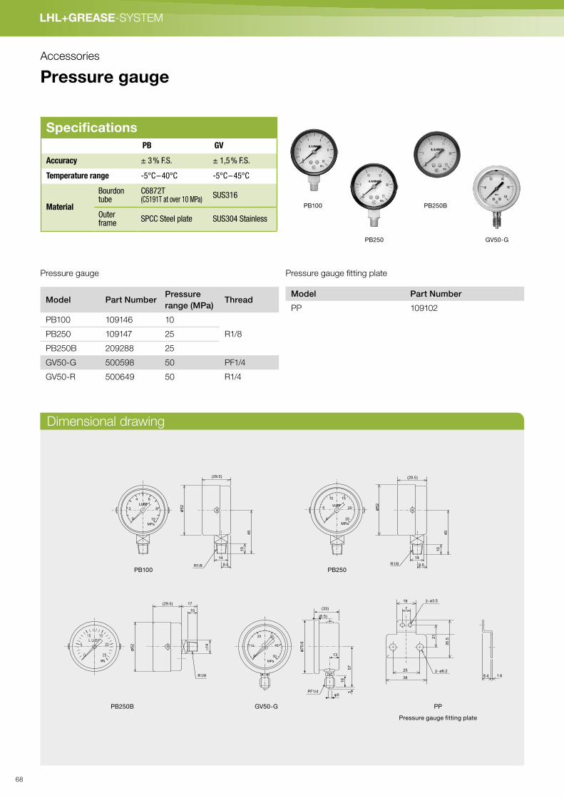
LHL+GREASE-SYSTEM
Dimensional drawing
Accessories
Pressure gauge
Model Part NumberPressure
range (MPa)Thread
PB100 109146 10
R1/8PB250 109147 25
PB250B 209288 25
GV50-G 500598 50 PF1/4
GV50-R 500649 50 R1/4
Model Part Number
PP 109102
Pressure gauge Pressure gauge fitting plate
PB250BPB100
PB250 GV50-G
SpecificationsPB GV
Accuracy ± 3 % F.S. ± 1,5 % F.S.
Temperature range -5°C – 40°C -5°C – 45°C
Material
Bourdontube
C6872T(C5191T at over 10 MPa)
SUS316
Outer frame
SPCC Steel plate SUS304 Stainless
MPa
0
2
4
10
ø52
45
10
9.5R1/8
(29.5)
6
8
14
PB100
MPa
0
5
10
25
ø52
45
10
9.5R1/8
(29.5)
15
20
14
PB250
18
7
38
25
21
35.5
2- ø3.5
2- ø6.2
8.4 1.6
φ5PF1/4
ø70.6
(33)
13
57
16
3
(6.5)
MPa
0
10
20
50
30
40
GV50-G PP
Pressure gauge fitting plate
ø52
□14
10
R1/8
(29.5) 17
PB250B
68

LH
L+
GR
EA
SE
- S
YS
TE
M
Dimensional drawing
Dimensional drawing
Grease filler pump
SpecificationsDischarge volume 1.2 mℓ/Stroke
Maximum pressure 40 MPa
Grease capacity 400 g
Weight 1.4 kg
340±5
363±5
ø62.7
ø10
ø14.5
120
175±5
*For use with LUBE original 400cc grease cartridges
Model Part Number
P3-C JC0005
Model Part Number
LG-400 252422
SpecificationsDischarge volume 540 mℓ/min
Discharge pressure 34.3 MPa
Working air pressure 0.4 - 0.7 MPa
Air consumption 315 ℓ/min (ANA)
Grease capacity 16 kg
Pump Weight 6 kg
110
24
310
298
62
208
555
170
80
Pneumatic pump for pail
Hand Grease gun
69

LHL+GREASE-SYSTEM
Accessories
Grease vacuum cleanerPneumatically operated grease vacuum removes excess grease. Compact and portable.
Reduces consumption of workshop rags.
Model Part No. Height × Width Weight
VACUUMER 222301 340×270mm 3.4kg
4
1
23
Items contained in standard set
1. Silent filter
2. Air Valve (To turn the Vaccum ON/OFF)
3. Air Inlet Push-to-connect Coupler
4. Vacuum Hose
70

LH
L+
GR
EA
SE
- S
YS
TE
M
Dimensional drawing
Proximity sensor for series progressive valve
Steel dust meter
Electrically monitors the movement of the indicator pin of progressive valve.
Proximity sensor can be used to monitor for a Progressive Valve or system failure,
and can also be used to monitor pump discharge time.
The New Cosmos SDM-72 steel dust meter employs a magnetic
balance type electromagnet induction method for measuring.
The SDM-72 is a useful and simple diagnostic tool for inspecting
the abrasion status of bearings and gears.
ø21
174
10
33
38
2-clamping nut
9
M12
Toothed washer
Indicator
SpecificationsE2E-X2E1 E2F-X2E1 E2F-X2Y1
Power voltage DC10-24V AC24-240V
Workingvoltage range
DC10-40V DC10-30V AC20-264V
Output Form DC 3 leads NPN AC 2 leads
DetectingDistance
2 mm ± 10%
Setting Distance 0 - 1.6 mm
Detecting Object Iron 12×1 mm
Protection class IEC Standards IP67
IEC Standards IP68
Model Part Number
E2E-X2E1 733225
E2F-X2E1 730797
E2F-X2Y1 730721
SpecificationsMeasurementprinciple
Magnetic balance type electromagnetic
Substancemeasured
Steel dust concentration in grease
Measurement range 0 to 19999 ppm (Wt)
Zero adjustment Automatic adjustment
Amount of sample 1.5 ml
Power 4× AA (R6) alkaline dry cells or AC adaptor
Battery life Up to 30 hours by alkaline cells
Operatingtemperature
0 to 40 °C
Dimensions W 84 × H 190 × D 40mm
Weight Approx. 500g (including batteries)
Model Part Number
SDM-72 —
71

LHL+GREASE-SYSTEM
Accessories
Solenoid valve
Filter regulator
Model Part Number
AW20-01BG 229570
Model Part No. Specifica-
tions
Working
voltage
Maximum
working
pressure
difference
AB31013 229439 Two-way AC100V 0.7MPa
AB31013 229440 AC200V
AB31013 229438 DC24V
VX3114-
1G
229548 Three-way AC100V
VX3114-
2G
229549 AC200V
VX3114-
5G
229550 DC24V
2-ø5.3
Installation hole
Bracket11
46
36
40
20 23 290±10
2-Rc1/8 (PT)P
Connectiondiameter
18
30
948 (
55)
10
68 (
78)
Two-way
30
20
Installation hole
14
.5
19
6
46.5
74.5
NO
P K
anal
2-ø5.3
29
18
20 22.5
20 23 290±10
Bracket
3-Rc1/8(PT)P
Three-way
Dimensional drawing
Dimensional drawing
Connection diameter Rc1/8
M5×0.8
Pressure gauge
164.5
72

LH
L+
GR
EA
SE
- S
YS
TE
M
Testing result: FS2 grease vs non-lubrication with self lubricating bushings
Pictured left is testing result of bearing surfaces without any
lubricant. End surface of bearing is changing shape.
This is caused by high temperature and damage at the sliding
surface.
Additionally, it was confirmed that OILES#500HP-101
is problematic in regards to keeping its performance
until target testing time.
LUBE FS2 has superior sliding characteristics. In this
test, the effect of the additives in the grease is also
superior. FS2 grease and its special additives combine
heavy load carry capacity with oxidation stability
to improve overall sliding characteristics.Testing result: Bearing condition
with FS2 grease.
Testing result: Bearing condition
without lubricant (1)
Testing result of the shaft condition-
with FS2 grease
Testing result: Bearing condition
without lubricant (2)
Imitationgrease
LUBE original cartridge greaseRegistration of Designs: Registration No. 1324342
Cap: Blue
Body: Green
Cap: Blue
Body: Green
定量バルブ構造
ピストン部でのグリース固着例 チェック部でのグリース固着例
1 Extreme wear and shape changes caused by poor lubrication at the ball screw.
2 Damage caused by premature wear at the ball screw.
e.g. Solidificationat the piston
e.g. Solidificationat the check valve
Please make sure to use Lube original grease cartridges designated by your machine manufacturer.
The use of non-specified or counterfeit grease may cause significant damage to the lubrication
system and key moving components of your machines.
Developed through the collaboration with our machine manufacturer partners, Lube original cartridge grease is specifically
designed to guarantee the long-term and stable performance of machinery. Using non-designated or counterfeit grease may
cause serious loss or damage not only to your lubrication system but also the key moving components of the machine.
This will result in machine breakdowns that require considerable recovery time and costs. Lube is not responsible for any
loss or damage caused by the use of non-designated or counterfeit grease.
Information provided by OILES CORPORATION
e.g. Metering valve failure from imitation grease
Warning!
73

LHL+FETT-SYSTEMEGREASE-SYSTEM
Accessories
Pumping unit
Assembly
HEX27(85)
M22x1.5
8
16
10
10
M22X1.5
1
2127
(28)
HEX14
R1/4 434
323 4-Rc1/4
522-R1/4
φ6
9
(33)
13
57
16
R1/4
ø27
ø2
7 ø22
Indication 8
G1/4
Indication 8
Indication 8
HEX27(85)
M22x1.5 Indication 6
Indication 6
G1/4Indication 6
688
Model Part Number
PUY-6 539291
Material: SCM435H
Model Part Number
BPY 530911
Material: A2011
Model Part Number
RTY 539310
Material: S45C
Model Part Number
SCY 550130
Material: SGP
Model Part Number
PUY-8 539292
Material: SCM435H
Model Part Number
SWY 530910
Material: Teflon
Model Part Number
JVY 530937
Material: S45C
Model Part Number
GV50-R 500649
(Pump)
SCY
RTY
JVY
C I O S E
OPERA T I ON
74

LH
L+
GR
EA
SE
- S
YS
TE
M
Operation chart
Setting of discharge volume/ Suggestions
Step 1
The grease is sent by the pump or the grease gun enters from the inlet of the
block upper part. The sent grease passes along the port shown in the dark gray
color, reaches the right-hand side of a piston "A", and moves piston "A" leftward.
At this time, the grease on the left-hand side of a piston "A" passes along the
port shown in the light gray color, and is discharged from the outlet of No. 2.
If piston "A" carries out a full stroke leftward, as shown to Fig. 2 by the dark gray
color, the port which results in surface of a piston "B" will be connected, and the
grease from a pump will move a piston "B" leftward through this port. At this
time, the grease on the left-hand side of a piston "B" is discharged from the
outlet of No. 7 through the port shown in the light gray color.
Like last time, if piston "B" carries out a full stroke leftward, as shown to Fig. 3
by the dark gray color, the port which results in right-hand side edge of piston
"C" will be connected, grease will pass along this port, and a piston "C" will be
moved leftward. At this time, the grease on the left-hand side of piston "C" is
discharged from a No. 5 outlet through the port shown in the light gray color.
If piston "C" carries out a full stroke, as shown by the dark gray color among the
right figure, the port which results in right-hand side edge of a piston "D" will be
connected, and a piston "D" will be moved leftward. At this time, the grease on
the left-hand side of a piston "D" is discharged from No. 3 outlet through the port
shown in the light gray color.
This time, as a result of piston's "D'"' carrying out a full stroke, as shown by the
dark gray color among the figure, the port which results in left-hand side edge of
a piston "A" is connected, and a piston "A" is moved rightward.
At this time, the grease on the right-hand side of piston "A" which worked as last
operation grease is discharged from a No. 1 outlet through the port shown in the
light gray color.
Grease will be discharged by the same repetition as henceforth in order of the
outlet of 8, 6, 4, 2, 7, 5, 3, and 1.
7
5
3
1
8
6
4
2
A
B
C
D
Grease inlet
Fig 1
1
3
5
7
2
4
6
8A
B
C
D
Grease inlet
Fig 27
5
3
1
8
6
4
2
A
B
C
D
Grease inlet
Fig 3
Fig 5
7
5
3
1
8
6
4
2
A
B
C
D
Grease inlet
Fig 47
5
3
1
8
6
4
2
A
B
C
D
Grease inlet
Step 3
Step 5
Step 2
Step 4
� Suggestions
1. Use only the specially designed SP fi ttings for discharge ports of the SP type valve.
2. When you attach the discharge port Outlet Check Body, please be sure to check whether the
Clamping Ring is set correctly. Moreover, when you attach SPB plug into the grease discharge
port, please be sure to remove the Clamping Ring, if present. If a Port Plug is attached with the
Clamping Ring set, the whole valve stops operating.
3. Use proper torque when installing AP & SP Progressive Block specialty adapters.
4. Installation will become difficult if assembly of AP & SP Progressive Blocks is begun with the
middle discharge ports. Begin assemble at one end and continue to the other on each side to
insure proper and more efficient assembly.
5. Use the correct washer and proper torque when installing AP & SP Progressive Block port plugs.
� Setting of discharge volume
As for each discharge port, 0.2 ml/stroke grease is discharged at the time of a pump operation.
If one discharge port is closed, the quantity from the closed port will be added to and discharged
by the next discharge port below.
Beispiel 4
×−7
×−5
×−3
148
8−×
4−×
2 28
6 28
Example
× : Plugged port will not discharge.1 : Discharge will be four (4) times the normal amount.2, 6 : Discharge will be twice the normal amount.
75

OIL- SYSTEMSYSTEMS
➔ PDI (Positive Displacement Injector)
➔ SLR (Single Line Resistance)
➔ Pneumatic (biodegredable oil)
➔ Progressive LUBFIT OIL SERIES ACCESSORIES
76

ÖL
-SY
STE
ME
➔ PDI
System-Layouts P. 78
PumpsAMZ-III P. 84
AMO-III DS P. 88
AMO- II -150S P. 90
AMI-300S · AMI-1000S P. 92
LT-S P. 94
ValvesJV P. 95
JVPA P. 96
PV P. 97
PVS P. 98
PJ P. 99
MO P. 100
MO2 · MO2C P. 101
MOS P. 102
MB P. 104
DVR P. 112
MIX · MIX-S P. 108
77
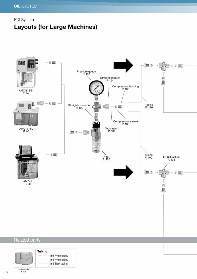
OIL-SYSTEM
PDI System
Layouts (for Large Machines)
Grease
Cleaner
S. 97
LRA
analysis
S. 226
●Zubehörteile
Pneumatic
pump for pail
S. 96
φ6 Stahlrohrleitung
φ4 Steel tubing
φ4 Nylon-Rohrleitung
Flexibler Schlauch
●Leitungen
LHL X-100cartridge Fett
S. 90
LUBE Hybrid Lubrication System (LHL) LHL Lubrication System
'
LRA analysis
P. 207
ø 6 Nylon tubing
ø 4 Nylon tubing
ø 4 Steel tubing
Tubing
●Zubehörteile
φ6 Nylon-Schlauch
φ4 Nylon-Schlauch
φ4 Stahlrohrleitung
●Leitungen
LRA-AnalyseS. 226
AMO-III DSP. 94
Pressure gauge P. 163
Straight connector P. 198
Compression sleeveP. 188
Tubing P. 190
PJ-3 Junction P. 138
Compression bushingP. 188
Straight adapterP. 194
FilterP. 166
AMO-II-150P. 96
Tubing P. 190
AMZ-IIIP. 90
Tube insertP. 189
Related parts
78

OIL
-SY
STE
M
Straight adapterP. 194
MO2C Metering valveP. 101
PJ-2 JunctionP. 138
Blanking plugP. 189
Nylon brush P. 202
MOS Metering valve P. 108
PVS Junction P. 104
Plug BPSP. 108
Closure plugP. 189
Mixing blockP. 114
Related partsP. 206
Luft
MO2C Metering valveP. 101
Blanking plug P. 189
MOS Metering valve P. 108
79

OIL-SYSTEM
●Zubehörteile
LRA-AnalyseS. 226
Positive Displacement Injector (PDI-) System für große Anlagen Öl Lubrication System
φ6 Stahlrohrleitung
φ4 Steel tubing
●Leitungen
PDI System
Layouts (for Large Machines)
Grease
Cleaner
S. 97
LRA
analysis
S. 226
●Zubehörteile
Pneumatic
pump for pail
S. 96
φ6 Stahlrohrleitung
φ4 Steel tubing
φ4 Nylon-Rohrleitung
Flexibler Schlauch
●Leitungen
LHL X-100cartridge Fett
S. 90
LUBE Hybrid Lubrication System (LHL) LHL Lubrication System
'
LRA analysis
P. 207
ø 6 Steel tubing
ø 4 Steel tubing
Tubing
8ℓ Metal ReservoirP. 184
AMI-300SP. 98
AMI-1000SP. 98
AMO-III DSP. 94
Straight adapter P. 194
Compression sleeve P. 188
Compression bushing P. 188
JV-3 Junction P. 101
PJ3-6 Junction P. 138
Tubing P. 190
Filter P. 166
Pressure gauge P. 163
Related parts
80

●Zubehörteile
LRA-AnalyseS. 226
Positive Displacement Injector (PDI-) System für große Anlagen Öl Lubrication System
φ6 Stahlrohrleitung
φ4 Steel tubing
●Leitungen
MO2 Metering valve
P. 101
JVPA JunctionP. 102
LU-DO SensorP. 172
Elbow connectorP. 198
Elbow adapterP. 196
Elbow connector P. 198
Indicator pinP. 201
Blanking plugP. 189
Straight connector P. 198
Tubing P. 190 Straight adapter
P. 194
Tubing P. 190
Tubing P. 190
Straight adapter P. 194
Indicator pin P. 201
MO2 Metering valve
P. 101
JVPA JunctionP. 102
MO2 Metering valve
P. 101
JVPA JunctionP. 102
81
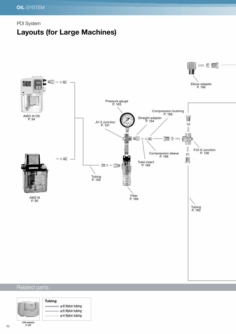
OIL-SYSTEM
φ8 Nylon-Rohrleitung
φ6 Nylon tubing
φ4 Nylon tubing
●Leitungen
LRA-AnalyseS. 226
Positive Displacement Injector (PDI-) System für große Anlagen Öl Lubrication System
●Zubehörteile
Air
AMO-III DSP. 94
JV-3 JunctionP. 101
Pressure gauge P. 163
Straight adapter P. 194
Compression bushing P. 188
Elbow adapterP. 196
PJ3-6 JunctionP. 138
Tubing P. 190
Compression sleeveP. 188
Tube insert P. 189
FilterP. 166
Tubing P. 190
AMZ-IIIP. 90
PDI System
Layouts (for Large Machines)
Related parts
Grease
Cleaner
S. 97
LRA
analysis
S. 226
●Zubehörteile
Pneumatic
pump for pail
S. 96
φ6 Stahlrohrleitung
φ4 Steel tubing
φ4 Nylon-Rohrleitung
Flexibler Schlauch
●Leitungen
LHL X-100cartridge Fett
S. 90
LUBE Hybrid Lubrication System (LHL) LHL Lubrication System
'
LRA analysis
P. 207
ø 8 Nylon tubing
ø 6 Nylon tubing
ø 4 Nylon tubing
Tubing
82

φ8 Nylon-Rohrleitung
φ6 Nylon tubing
φ4 Nylon tubing
●Leitungen
LRA-AnalyseS. 226
Positive Displacement Injector (PDI-) System für große Anlagen Öl Lubrication System
●Zubehörteile
Air
Air-Oil valve MIX P. 108
Straight adapterP. 194
Tube insertP. 189
Compression sleeve P. 188
Air-Oil sensorP. 168
Elbow adapterP. 196
Compression bushing P. 188
Filter regulator P. 163
Straight connectorP. 198
Solenoid P. 163
Closure plugsP. 189
Nozzle adapter P. 219
Compression bushingP. 188
Compression sleeveP. 188
Push-in fittingP. 201
MIX-SP. 114
Nozzle adapter P. 206
EliminatorP. 168
Tube insertP. 189
MIX-SP. 114
83

System-Komponenten
OIL-SYSTEM
PDI System
AMZ-III (Automatic intermittent gear pump)
1.8 ℓ 3 ℓ
Model Reference
Model Part Number
AMZ-III -1 285017
AMZ-III -1-3 285024
AMZ-III -2 285016
AMZ-III -2-3 285023
AMZ
Voltage
1.8 ℓ Resin reservoirs3 ℓ Resin reservoirs3 ℓ Metal reservoirs4 ℓ Metal reservoirs8 ℓ Metal reservoirs
Blank3
30
40
80
Reservoir capacity
ResinFoot MountWall Mount
BlankF
B
Reservoir Mounting Position
*Metal reservoir only
*Pump is installed on the rightside, if a metal reservoir isselected.
AC100Vφ1AC200Vφ1AC230Vφ1
1
2
23
F-3D Filter
P. 166
Metal reservoirs
P. 174
Related parts
Specifications
Pump
Dischargevolume
90 mℓ/min (50Hz), 110 mℓ/min (60Hz)
Dischargepressure
1.5 MPa/217.5psi(safety valve set pressure)
Motor
Voltage /current
AC100V/1.5A, AC200V/0.8A (50Hz)AC100V/1.3A, AC200V/0.7A (60Hz)
Output 19W (50Hz), 18W (60Hz) Shading motor
Emergencydetection
Oil levelswitch
Contact type (NO) ON at low levelContact capacity 0.5A, AC DC200V/30W smaller
Pressureswitch
Contact type (NO)Operating pressure: 1.3M ONReset pressure: 0.9MPa OFFContact capacity AC DC250V/2A
Max.Min.
OperationDischarge time: 1 min.Interval time: 3 min.
Working viscosityrange
50-1300 mm2/S (50Hz)
Reservoircapacity
1.8ℓ, 3ℓ (plastic) 3ℓ, 4ℓ, 8ℓ (sheet metal)
Weight 1.8ℓ: 2.7kg 3ℓ: 3.6kg
External fuse 100V/2.0A, 200V/1.0A
ModelPart
No.Voltage
Tank
capacity
Working
viscosity
range
1
AMZ-3-
100SL-
18LP
285224 100V 1.8L 22 ~ 800 mm2/S
2
AMZ-3-
100SL-
18LP
285426 200V 1.8L 22 ~ 800 mm2/S
3AMZ-3-
23285433 250V 1.8L 22 ~ 800 mm2/S
Low viscosity oil pump
Adapters
P. 194
Compression parts
P. 188
Pressure gauge
P. 163
JVPA Junction
P. 102
For MO2(C) Valve
MO2(C) Metering valve
P. 101
MO Metering valve
P. 100
MOS Metering valve
P. 102
MB Metering valve
P. 104
MIX-S Metering valve
P. 108
PV Junction
P. 97
For MO Valve
PVS Junction
P. 98
For MOS Valve
Tubing
P. 19084

OIL
-SY
STE
M
(25
6)
171
147
166
17
M10×1
12
0
54
(26
2)
17
7
234
270
35
13
5
63
Part Number
529409
Part Number
529409
Wiring portWiring port
Discharge port M10×1
Discharge port
Oil fill cap
Oil fill cap
2×M6
Installation hole
2×M6
Installation holeg
Strainer
Suction filter set Suction filter set
Part Number
521037
Part Number 489011 Part Number 489011
Part Number
521037
Improper handling can result in a death or serious injury Electrical shock may be received under certain conditions Be sure to ground.
Dimensional drawing
Hydraulic circuit drawing Wiring diagram
P
C
O
Y
X
PRESS. SW
OIL LEVEL. SW
POWER
EMG. OUT
E Thermal protector
RV
M
85
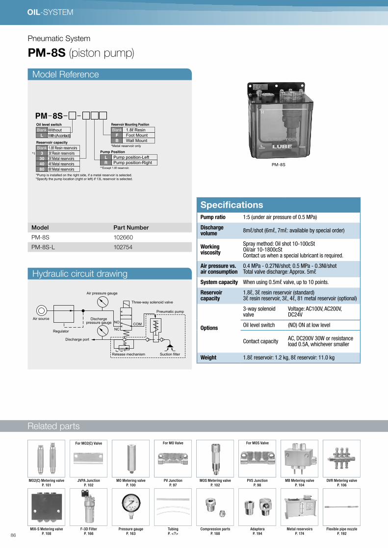
Related parts
OIL-SYSTEM
Pneumatic System
PM-8S (piston pump)
PM-8S
Model Reference
Hydraulic circuit drawing
Model Part Number
PM-8S 102660
PM-8S-L 102754
PM 8S
Without
With (A contact)
Blank
L
Oil level switch
*Specify the pump location (right or left) if 13L reservoir is selected.
*1
*Pump is installed on the right side, if a metal reservoir is selected.
1.8ℓ Resin reservoirs3ℓ Resin reservoirs3ℓ Metal reservoirs4ℓ Metal reservoirs8ℓ Metal reservoirs
Blank
3
30
40
80
Reservoir capacity
1.8ℓ ResinFoot MountWall Mount
Blank
F
B
Reservoir Mounting Position
*Metal reservoir only
**Except 1.8ℓ reservoir.
Pump position-Left
Pump position-Right
Pump Position
L
R
SpecificationsPump ratio 1:5 (under air pressure of 0.5 MPa)
Dischargevolume
8mℓ/shot (6mℓ, 7mℓ: available by special order)
Workingviscosity
Spray method: Oil shot 10-100cStOil/air 10-1800cStContact us when a special lubricant is required.
Air pressure vs.air consumption
0.4 MPa - 0.27Nl/shot; 0.5 MPa - 0.3Nl/shotTotal valve discharge: Approx. 5mℓ
System capacity When using 0.5mℓ valve, up to 10 points.
Reservoircapacity
1.8ℓ, 3ℓ resin reservoir (standard)3ℓ resin reservoir, 3ℓ, 4ℓ, 81 metal reservoir (optional)
Options
3-way solenoidvalve
Voltage: AC100V, AC200V,DC24V
Oil level switch (NO) ON at low level
Contact capacityAC, DC200V 30W or resistanceload 0.5A, whichever smaller
Weight 1.8ℓ reservoir: 1.2 kg, 8ℓ reservoir: 11.0 kg
NO
NC
COM
Air source
Regulator
Air pressure gauge
Dischargepressure gauge
Three-way solenoid valve
Release mechanism Suction filter
Pneumatic pump
Discharge port
F-3D Filter
P. 166
Metal reservoirs
P. 174
Adaptera
P. 194
Compression parts
P. 188
Pressure gauge
P. 163
MIX-S Metering valve
P. 108
Tubing
P. <?>
MO2(C) Metering valve
P. 101
MO Metering valve
P. 100
MOS Metering valve
P. 102
MB Metering valve
P. 104
PV Junction
P. 97
For MO Valve
PVS Junction
P. 98
For MOS Valve
Flexible pipe nozzle
P. 192
DVR Metering valve
P. 106
JVPA Junction
P. 102
For MO2(C) Valve
86

OIL
-SY
STE
M
Dimensional drawing
[PM-8S]
Rc1/8
Discharge port
M10×1
72.5
30
27
72.53-ø 6.5
Installation hole
Air inlet
12
0
160
18
4
17
4
87

System-Komponenten
OIL-SYSTEM
PDI System
AMO–III DS (Automatic intermittent gear pump)
Model Reference
Related parts
AC100Vφ1AC200Vφ1
1
2
Voltage
1.8ℓ Resin reservoirs3ℓ Resin reservoirs3ℓ Metal reservoirs4ℓ Metal reservoirs8ℓ Metal reservoirs
Blank3
30
40
80
Reservoir capacity
ResinFoot MountWall Mount
BlankF
B
Reservoir Mounting Position
*Metal reservoir only
* Pump is installed on the right side, if a metal reservoir is selected.
1.8 ℓ 3 ℓ
Model Part Number
AMO-III DS-1 285301
AMO-III DS-1-3 285303
AMO-III DS-2 285302
AMO-III DS-2-3 285304
No. ModelPart
No.Voltage
Tank
capacity
Working
viscosity
range
1AMO-IIIDSL-1
285331 100V 1.8L 10 ~ 1800 mm2/S
2AMO-IIIDSL-2
285332 200V 1.8L 10 ~ 1800 mm2/S
3AMO-
IIIDSL-2285333 100V 3.0L 10 ~ 1800 mm2/S
4AMO-
IIIDSL-2285334 200V 3.0L 10 ~ 1800 mm2/S
Low viscosity oil pump
MO2(C) Metering valve
P. 101
MO Metering valve
P. 100
MOS Metering valve
P. 102
MB Metering valve
P. 104
MIX-S Metering valve
P. 108
PV Junction
P. 97
For MO Valve
PVS Junction
P. 98
For MOS Valve
F-3D Filter
P. 166
Metal reservoirs
P. 174
Adaptera
P. 194
Compression parts
P. 188
Pressure gauge
P. 163
Tubing
P. 190
JVPA Junction
P. 102
For MO2(C) Valve
Specifications
Pump
Dischargevolume
150 mℓ/min (50Hz), 180 mℓ/min (60Hz)
Dischargepressure
2.0 MPa/284psi (safety valve setting)
MotorPower
AC100V/0.83A, AC200V/0.41A (50Hz)AC100V/0.64A, AC200V/0.33A (60Hz)
Output 20W (50Hz/ 60Hz) Capacitor motor
Controller
TimerCounter
Discharge time adjustable range: 1 - 99 sec.Interval time adjustable range: 1 - 9999 min. 1 - 9999 counts
Emergencyoutput
Contact type (NO)
Contact capacity AC250V 1.5A
Emergencydetection
Oil levelswitch
Contact type (NO) ON at low level
Pressureswitch
Contact type (NC)Operating pressure: 1.7 MPa OFFReset pressure: 0.9 MPa ON
Liquidcrystaldisplay
INTERVAL display: 'INT'
DIS-CHARGE
display: 'DIS'
ALARMLow oil level: ‘OILLEVEL ERR’Low pressure: ‘PRESSURE ERR’
Workingviscosityrange
68 – 1800 mm2/S (50Hz)
Reservoircapacity
1.8ℓ, 3ℓ (plastic) 3ℓ, 4ℓ, 8ℓ (sheet metal)
Weight1.8ℓ Reservoirs: 3.2kg 3ℓ Reservoirs: 4kg
88

OIL
-SY
STE
M
Hydraulic circuit drawingController
Wiring diagram
Dimensional drawing
Power E Emergency
output
Count in
(Only count in model)
RV
M
LCD shows the below:
INTERVAL → INTDISCHARGE → DISALARM → Low oil level OILLEVEL ERR
Low pressure PRESSURE ERR
LCD
“RESET & FEED”key
“Enter” key
“UP” key
“DOWN” key
Operation panel of the controller
CB-6 CS-6 SA6-20 EA6-22
or
Parts for connecting to the discharge port
271
17
2
Installation hole
Installationhole
2-ø6.5
170
167
190
12
4
88
.5
Discharge port
Rc1/8 Rc1/8
14
3.5
89
234
275
27
9
174
2-ø 9
Pressure gauge installation port
Rc1/8Rc1/8
Pressure gauge installation port
Strainer Strainer
Oil fill capOil fill cap
AuslassöffnungDischarge port
Suction filter set
Part Number 489011
Suction filter set
Part Number 489011
withP/Swith
P/S
Part Number
529409
Part Number
529409
Part Number
521037
Part Number
521037
Improper handling can result in a death or serious injury Electrical shock may be received under certain conditions Be sure to ground.
1.8ℓ 3ℓ
/
89

System-Komponenten
OIL-SYSTEM
PDI System
AMO-II-150S (Automatic intermittent gear pump)
Model Reference
Related parts
1.8 ℓ 3 ℓ
Model Part Number
AMO-II -150S-1 202067
AMO-II-150S-1-3 202069
AMO-II-150S-1-P 202071
AMO-II-150S-1-P-3 202073
AMO-II-150S-2 202068
AMO-II-150S-2-3 202070
AMO-II-150S-2-P 202072
AMO-II-150S-2-P-3 202074
AMO 150S
AC100Vø 1
AC200Vø 1
1
2
Voltage
Pressure Switch
1.8ℓ Resin reservoirs3ℓ Resin reservoirs3ℓ Metal reservoirs4ℓ Metal reservoirs8ℓ Metal reservoirs
Blank3
30
40
80
Reservoir capacity
ResinFoot MountWall Mount
BlankF
B
Reservoir Mounting Position
Without Pressure SwitchWith Pressure Switch
BlankP
*Metal reservoir only
*Pump is installed on the right side, if a metal reservoir is selected. Specifications
Pump
Dischargevolume
150 mℓ/ min (50Hz), 180 mℓ/ min (60Hz)
Dischargepressure
2.0 Mpa (20kgf/cm2) 284psi
Motor
Voltage/current
AC100Vø1/0.83A, AC200Vø1/0.41A (50Hz)AC100Vø1/0.64A, AC200Vø1/0.33A (60Hz)
Output 20W (50Hz/ 60Hz) Condenser Motor
Emergencydetection
Oil levelswitch
Contact type (NO) ON at low level
Contact capacity 0.5A ACDC200V/30W smaller
Pressureswitch
Contact type (NC)Operating pressure: 1.7MPa OFFReset pressure: 0.9MPa ONContact capacity AC DC250V/3A
Dischargetime
Max. Discharge time: 99secMin. Interval time: 1min
Working viscosityrange
68-1800 mm2/S (50Hz)
Reservoircapacity
1.8ℓ, 3ℓ (plastic) 3ℓ, 4ℓ, 8ℓ (sheet metal)
Weight1.8ℓ Reservoirs: 3.2kg 3ℓ Reservoirs: 4kg (plastic)
MO2(C) Metering valve
P. 101
MO Metering valve
P. 100
MOS Metering valve
P. 102
MB Metering valve
P. 104
MIX-S Metering valve
P. 108
PV Junction
P. 97
For MO Valve
PVS Junction
P. 98
For MOS Valve
F-3D Filter
P. 166
Metal reservoirs
P. 174
Adapters
P. 194
Compression parts
P. 188
Pressure gauge
P. 163
Tubing
P. 190
JVPA Junction
P. 102
For MO2(C) Valve
90

OIL
-SY
STE
M
Dimensional drawing
Hydraulic circuit drawing Wiring diagram
E
OL
COM
P/SW
Power
1 2 3 4 5 6
Emergency output
RV
PG
M
170
167
190
12
4
88
.5
26
1
17
2
Installation hole
Discharge port
RC1/8
Pressure gauge installation port Oil fill cap
Wiring port
2-φ6.5
RC1/8
LUBE
MPa0
1
2
5
0
3
4
Option / Pressure gauge
PB-50B
Strainer
RC1/8
Discharge port
26
4
17
4
Installation hole
2-ø 9
14
3.5
234
275
Auslassöffnung
RC1/8
RC1/8
Wiring port
Oil fill cap
89
LUBE
MPa0
1
2
5
0
3
4
Pressure gauge installation port
Strainer
PB-50B
RC1/8
AuslassöffnungDischarge port
Pressure gauge installation port
Suction filter set
Part Number 489011
Suction filter set
Part Number 489011
Part Number
529409
Part Number
521037
Part Number
521037
Part Number
529409
1.8ℓ 3ℓ
Improper handling can result in a death or serious injury Electrical shock may be received under certain conditions Be sure to ground.
CB-6 CS-6 SA6-20 EA6-22
or
Parts for connecting to the discharge port
91

System-Komponenten
OIL-SYSTEM
PDI System
AMI-300S AMI-1000S (Automatic intermittent gear pump)
Model Reference
Related parts
AMI-300S AMI-300S
AMI S
AC100Vø 1
AC200Vø 3
1
2
Voltage
300mℓ/min1000mℓ/min
330mℓ/min1100mℓ/min
300
1000
Discharge volume
(50Hz/60Hz)
//
2ℓ Metal3ℓ Resin reservoirs3ℓ Metal reservoirs4ℓ Metal reservoirs8ℓ Metal reservoirs
2
3
30
40
80
Reservoir capacity
*Except 2ℓ reservoir.
Resin reservoirsFoot MountWall Mount
BlankF
B
Reservoir Mounting Position
Pump position-LeftPump position-Right
Pump Position
*If the controller is used, please select “With”.
WithoutWith
BlankL
Oil level switch
L
R
Specifications AMI-300S AMI-1000S
PumpDischarge volume
300 mℓ/min (50Hz)330 mℓ/min (60Hz)
1000 mℓ/min (50Hz)1100 mℓ/min (60Hz)
Discharge pressure 2.5 MPa (25kgf/cm2) 362.5 psi
MotorPower
AC100Vø 1/0.76/0.74A
(Condenser 11 µF)
AC100Vø 1/1.2/1.19A (50Hz)
(Condenser 20 µF)
AC200Vø 3/0.32A/0,3A AC200Vø 3/0.5/0.43A
Output 40W Induction motor 60W Induction motor
Operation rateMax. Discharge time: 3minMin. Interval time: 3min
Working viscosity range 65-1300 mm2/S (50Hz)
Reservoir capacity Standard reservoir up to 50 liters available.
Weight 4.4 kg 7.1 kg
OthersWith Pressure relief mechanism, Motor rotation: Clockwise
Meca-tron controller is available.
External fuse 100V/2A 200V/1A 100V/3A 200V/1A
Model Part Number
AMI-1000S-1 202103
AMI-1000S-2 202101
AMI-300S-1 202033
AMI-300S-2 202034
F-3D Filter
P. 166
Metal reservoirs
P. 174
Adapters
P. 194
Compression parts
P. 188
Pressure gauge
P. 163
Tubing
P. 190
MO2,MO2C Metering valve
P. 101
MO Metering valve
P. 100
MOS Metering valve
P. 102
MB Metering valve
P. 104
For MO Valve
P. 97
For MO Valve
PVS Junction
P. 98
For MOS Valve
JVPA Junction
P. 102
For MO2(C) Valve
92

OIL
-SY
STE
M
Dimensional drawing (AMI-300S) Dimensional drawing (AMI-1000S)
Wiring diagramHydraulic circuit drawing
RV
M
Option
31
5
Adaptation cable ø 6 - ø 12
15
17
1
88
14
14
0
φ100
6
Cable outlet
Discharge port
for ø 6 tubing
4-ø 6.5
Installation
hole
ø 21
Flange
Relief valve
Pressure relief valve
Wiring port
Suction filter set
Part Number 48908
ø 66
908.8
185
140
325
4 - ø 6.5
φ120
7
Adaptation cable ø 6 - ø 12
Cable outlet
Installation
hole
Relief valve
Discharge port
Discharge port
for ø 6 tubing
Suction filter set
Part Number 48908
U V W
T S R
U V W U1
C
U2 Z2
20μF
U1
C
U2 Z2
11μFTSR
Three-phaseconnection
Single phaseconnection
Three-phaseconnection
Single phaseconnection
Power PowerAC100V
Power PowerAC100V
AMI-300S AMI-1000S
AMI-300S AMI-1000S
Parts for connecting to the discharge port
CN-6 CS-6
Parts for connecting to the discharge port
CB-6 CS-6
93

System-Komponenten
OIL-SYSTEM
PDI System
LT-S (Manually operated intermittent piston pump)
Dimensional drawing
Related parts
LT-S
Specifications
PumpDischarge volume 8 mℓ/Shot
Discharge pressure 3.4 MPa (Safety valve set pressure)
Working viscosity range 65 – 1300 mm2/s
Reservoir capacity 260 mℓ (Resin)
Weight 1.2 kg
Others Depressurizing mechanism is built-in
9680
223
55
Installationhole
3-ø 6.5
Cap
Reservoir
ø 72
69 (128)
Lever
4363
9
Discharge port
Rc1/8
Approximately 60 degrees
Model Part Number
LT-S 103421
CB-6 CS-6 SA6-20 EA6-22
or
Parts for connecting to the discharge port
F-3D Filter
P. 166
Adapters
P. 194
Compression parts
P. 188
Pressure gauge
P. 163
MO2 , MO2C Metering valve
P. 101
MO Metering valve
P. 100
MOS Metering valve
P. 102
MB Metering valve
P. 104
PV Junction
P. 97
For MO Valve
Tubing
P. 190
For MOS Valve
P. 98
For MOS Valve
JVPA junction
P. 102
For MO2(C) Valve
94
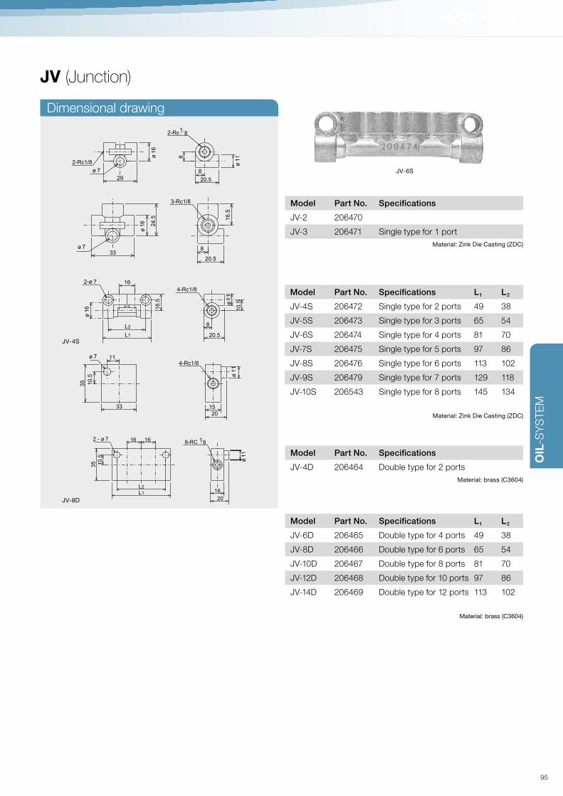
OIL
-SY
STE
M
JV (Junction)
JV-6S
Dimensional drawing
20.5
8
2-Rc1/8
29
ø 1
6
ø 7
ø 1
18
2-Rc1
8
33
ø 1
6
8
20.5
ø 7
3-Rc1/8
16.5
24.5
35 10.5
ø 7
4-Rc1/8
33
11
15
20
ø 1
1
20.5
8
4-Rc1/8
10.5
16
ø 1
1
16.5
ø 1
6
2-ø 7
L2
L1
35 10
.5
16 16
16
20
2 - ø 78-RC
18
L2
L1
ø 1
1
JV-4S
JV-8D
Model Part No. Specifications
JV-2 206470
JV-3 206471 Single type for 1 port
Material: Zink Die Casting (ZDC)
Model Part No. Specifications
JV-4D 206464 Double type for 2 ports
Material: brass (C3604)
Model Part No. Specifications L1 L2
JV-4S 206472 Single type for 2 ports 49 38
JV-5S 206473 Single type for 3 ports 65 54
JV-6S 206474 Single type for 4 ports 81 70
JV-7S 206475 Single type for 5 ports 97 86
JV-8S 206476 Single type for 6 ports 113 102
JV-9S 206479 Single type for 7 ports 129 118
JV-10S 206543 Single type for 8 ports 145 134
Material: Zink Die Casting (ZDC)
Model Part No. Specifications L1 L2
JV-6D 206465 Double type for 4 ports 49 38
JV-8D 206466 Double type for 6 ports 65 54
JV-10D 206467 Double type for 8 ports 81 70
JV-12D 206468 Double type for 10 ports 97 86
JV-14D 206469 Double type for 12 ports 113 102
Material: brass (C3604)
95
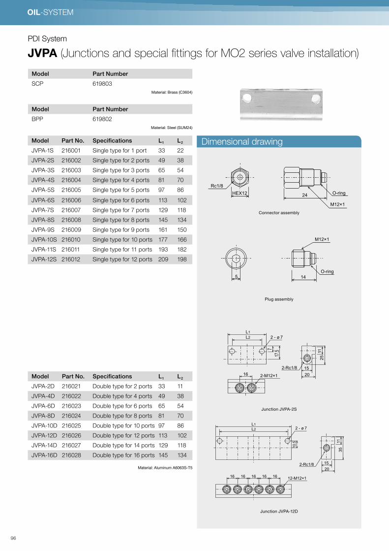
OIL-SYSTEM
PDI System
JVPA (Junctions and special fittings for MO2 series valve installation)
Dimensional drawing
M12×1
O-ring
Rc1/8
24HEX12
M12×1
O-ring5 14
Plug assembly
Connector assembly
Model Part Number
SCP 619803
Material: Brass (C3604)
Model Part Number
BPP 619802
Material: Steel (SUM24)
12-M12×1
L2
L1
L2
L1
2 - ø 7
16 16
16
16 16 16
2-M12×1
2 - ø 7
10.5
17.5
7
20
2-Rc1/8
11
35
15
20
2-Rc1/8
11
25
15
12-M12×1
L2
L1
L2
L1
2 - ø 7
16 16
16
16 16 16
2-M12×1
2 - ø 7
10.5
17.5
7
20
2-Rc1/8
11
35
15
20
2-Rc1/8
11
25
15
Junction JVPA-12D
Junction JVPA-2S
Model Part No. Specifications L1 L2
JVPA-1S 216001 Single type for 1 port 33 22
JVPA-2S 216002 Single type for 2 ports 49 38
JVPA-3S 216003 Single type for 3 ports 65 54
JVPA-4S 216004 Single type for 4 ports 81 70
JVPA-5S 216005 Single type for 5 ports 97 86
JVPA-6S 216006 Single type for 6 ports 113 102
JVPA-7S 216007 Single type for 7 ports 129 118
JVPA-8S 216008 Single type for 8 ports 145 134
JVPA-9S 216009 Single type for 9 ports 161 150
JVPA-10S 216010 Single type for 10 ports 177 166
JVPA-11S 216011 Single type for 11 ports 193 182
JVPA-12S 216012 Single type for 12 ports 209 198
Model Part No. Specifications L1 L2
JVPA-2D 216021 Double type for 2 ports 33 11
JVPA-4D 216022 Double type for 4 ports 49 38
JVPA-6D 216023 Double type for 6 ports 65 54
JVPA-8D 216024 Double type for 8 ports 81 70
JVPA-10D 216025 Double type for 10 ports 97 86
JVPA-12D 216026 Double type for 12 ports 113 102
JVPA-14D 216027 Double type for 14 ports 129 118
JVPA-16D 216028 Double type for 16 ports 145 134
Material: Aluminum A6063S-T5
96

OIL
-SY
STE
M
PV (Junction for MO valve)
Dimensional drawing
33
8
20.5
12.5
2-M10×1
16
.5
Rc1/8
ø 7
ø 1
6
φ11
20.5
12.5
10.52-M10×1
16
16
L2
L1
2 - ø 7 Rc1/8
ø 1
1
35 10
.5
15
20
11
33
2-Rc1/8
2-M10×1 ø 7
35 10
.5
16 15
20
Rc1/8
2-M10×1
2 - ø 7
L2
L1
PV-7
Model Part No. Specifications
PV-1 206481 Single type for 1 port
Material: Zinc Die Casting (ZDC)
Model Part No. Specifications L1 L2
PV-2 206482 Single type for 2 ports 49 38
PV-3 206483 Single type for 3 ports 65 54
PV-4 206484 Single type for 4 ports 81 70
PV-5 206485 Single type for 5 ports 97 86
PV-6 206486 Single type for 6 ports 113 102
PV-7 206487 Single type for 7 ports 129 118
PV-8 206489 Single type for 8 ports 145 134
Material: Zink Die Casting (ZDC)
Model Part No. Specifications
PV-2D 206491 Double type for 2 ports
Material brass C3604
Model Part No. Specifications L1 L2
PV-4D 206492 Double type for 4 ports 49 38
PV-6D 206493 Double type for 6 ports 65 54
PV-8D 206494 Double type for 8 ports 81 70
PV-10D 206495 Double type for 10 ports 97 86
PV-12D 206496 Double type for 12 ports 113 102
Material brass C3604
97
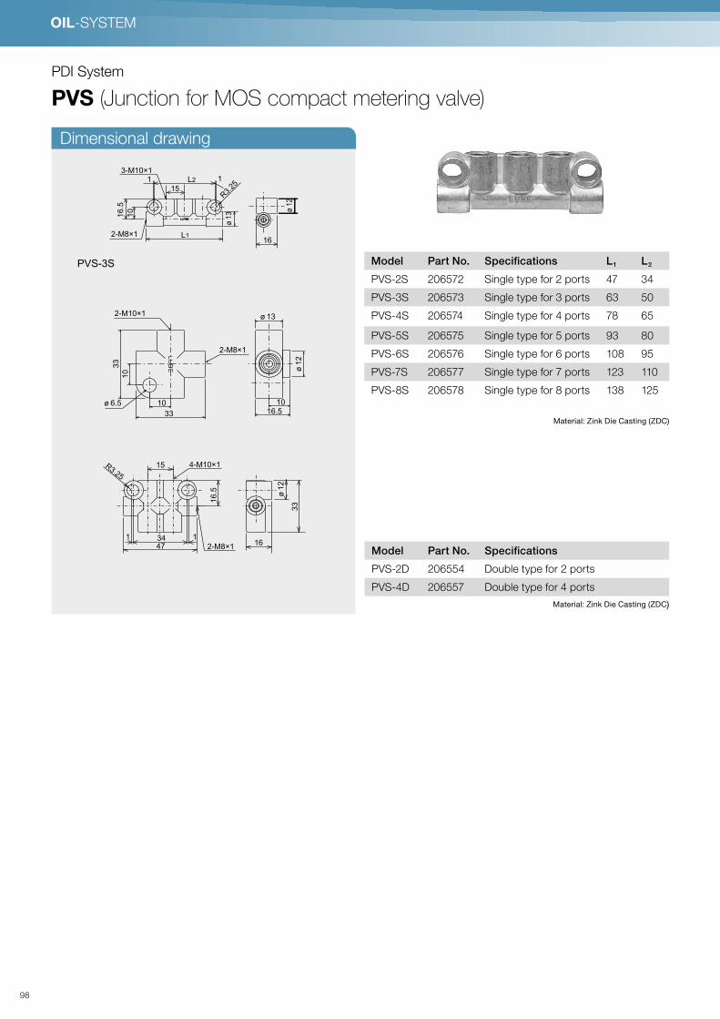
OIL-SYSTEM
PDI System
PVS (Junction for MOS compact metering valve)
Dimensional drawing
16.5
10
33
10
33
10
2-M8×1
2-M10×1
ø 1
2
ø 13
ø 6.5
1 1
16.5
ø 1
32-M8×1
R3.2
5
3-M10×1
10
L2
L116
ø 1
2
15
16
15
1 1
16.5
R3.25
33
2-M8×1
4-M10×1
47
34
ø 1
2
PVS-3S
Model Part No. Specifications
PVS-2D 206554 Double type for 2 ports
PVS-4D 206557 Double type for 4 ports
Material: Zink Die Casting (ZDC)
Model Part No. Specifications L1 L2
PVS-2S 206572 Single type for 2 ports 47 34
PVS-3S 206573 Single type for 3 ports 63 50
PVS-4S 206574 Single type for 4 ports 78 65
PVS-5S 206575 Single type for 5 ports 93 80
PVS-6S 206576 Single type for 6 ports 108 95
PVS-7S 206577 Single type for 7 ports 123 110
PVS-8S 206578 Single type for 8 ports 138 125
Material: Zink Die Casting (ZDC)
98

OIL
-SY
STE
M
PJ (Junction for main tubing)
Example of connecting nylon tubing
Dimensional drawing
Model Part No. Specifications
PJ2-6 206452 Two-way
PJ3-6 206453 Three-way
PJ4-6 206454 Four-way
PJ4S-6 206461 Four-way
Material: Zink Die Casting (ZDC)
20.58
29
2-M10×1
ø 7
ø 1
6
ø 1
1
12.5
33
20.5
8
16.5
3-M10×1
ø 1
1ø 1
6
ø 712.5
PJ2-6
33
33
20.5
4-M10×1
ø 7
ø 1
6
ø 1
1
12.5
20.5
12.5
10.5
ø 1
6 16.5
4-M10×12 - ø 7
ø 1
1
49
38
16
PJ4-6
PJ4S-6
CB-6 TI-6
NT-6
CS-6
99
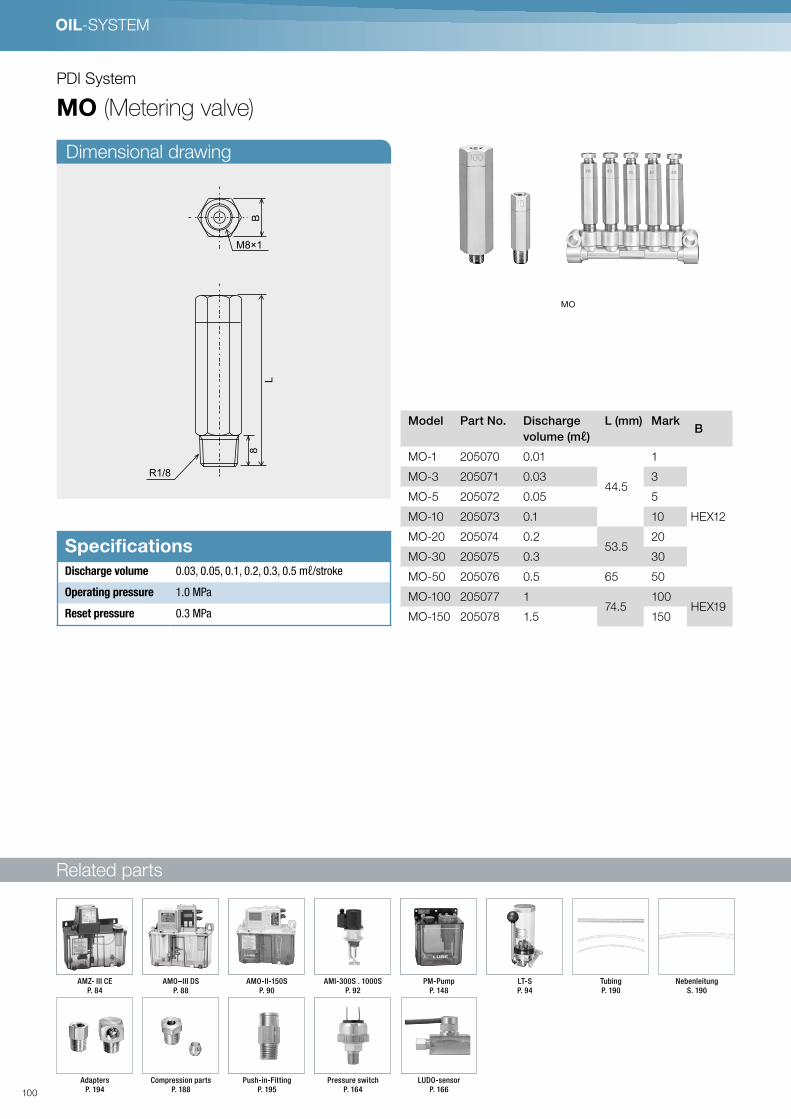
System-Komponenten
OIL-SYSTEM
Dimensional drawing
PDI System
MO (Metering valve)
Related parts
MO
R1/8
L
BM8×1
8
Model Part No. Discharge
volume (mℓ)
L (mm) MarkB
MO-1 205070 0.01
44.5
1
HEX12
MO-3 205071 0.03 3
MO-5 205072 0.05 5
MO-10 205073 0.1 10
MO-20 205074 0.253.5
20
MO-30 205075 0.3 30
MO-50 205076 0.5 65 50
MO-100 205077 174.5
100HEX19
MO-150 205078 1.5 150
SpecificationsDischarge volume 0.03, 0.05, 0.1, 0.2, 0.3, 0.5 mℓ/stroke
Operating pressure 1.0 MPa
Reset pressure 0.3 MPa
Nebenleitung
S. 190
Adapters
P. 194
Compression parts
P. 188
Pressure switch
P. 164
LUDO-sensor
P. 166
Push-in-Fitting
P. 195
AMO–III DS
P. 88
AMO-II-150S
P. 90
AMI-300S . 1000S
P. 92
PM-Pump
P. 148
LT-S
P. 94
AMZ- III CE
P. 84
Tubing
P. 190
100

OIL
-SY
STE
M
Branch tubing
P. 190
Adapters
P. 194
Compression parts
P. 188
Pressure switch
P. 164
LUDO-sensor
P. 166
Push-in-Fitting
P. 195
AMO–III DS
P. 88
AMO-II-150S
P. 90
AMI-300S . AMI-1000S
P. 92
Pump PM-8S
P. 148
LT-S
P. 94
AMZ- III CE
P. 84
Tubing
P. 190
MO2 · MO2C (Metering valve)
Specifications
Related parts
MO2
MO2
MO2C
MO2C
Operation Sequence
Start of pum
p operation
Start of pressure rise
Va
lve
op
en
s
Pressure starts rising beforedischarge of grease
1. Before the discharge
(Start of pressure rise)
2. Pump pressurizing
Completion of discharge (under pressure)
3. Measuring
(piston returning)
Valve begins toDischarge dischargeDischarge
O-ringCollar
A
Check valve
Inner pressure relieves
Depressed
Pump operation Pump stopsP
um
p re
lief o
pens
Pu
mp
sto
ps
Inner pressure relieves
Return of valve piston
Fin
ish
O-ring and collar go up
and push up the grease
(oil) in the measuring
chamber.
Spring starts
pushing down
O-ring and collar.
In the meantime,
the path (A) opens
up and the tip of
the check valve
seals the path from
the junction.
Grease (oil) refills
the measuring
chamber.
M12×1
O-ring
M8×1
LH
EX
12
□10
3 3
A
Discharge volume
Manufacturing lot
M12×1
O-ring
φ4 Nylon tubing
LH
EX
12
□10
3 3
A
Discharge volume
Manufacturing lot
SpecificationsDischarge volume 0.03, 0.05, 0.1, 0.2, 0.3, 0.5 mℓ/stroke
Operating pressure 1.0 MPa
Reset pressure 0.3 MPa
Model Part No. Discharge
volume (mℓ)
L
(mm)
Mark
MO2-3 205761 0.03 3
HEX12
MO2-5 205762 0.05 48 5
MO2-10 205763 0.1 10
MO2-20 205764 0.2 20
MO2-30 205765 0.3 64 30
MO2-50 205766 0.5 50
MO2C-3 205751 0.03 3
MO2C-5 205752 0.05 53.5 5
MO2C-10 205753 0.1 10
MO2C-20 205754 0.2 20
MO2C-30 205755 0.3 69.5 30
MO2C-50 205756 0.5 50
101

System-Komponenten
OIL-SYSTEM
Adapters (SAS) Plug (BPS)
PDI System
MOS (Compact metering valve)
Related parts
Model Part No. Discharge
volume (mℓ)
Mark
MOS-1 205300 0.01 1
MOS-3 205301 0.03 3
MOS-5 205302 0.05 5
MOS-10 205303 0.1 10
SpecificationsDischarge volume 0.01, 0.03, 0.05, 0.1 mℓ/Stroke
Operating pressure 0.9 MPa
Reset pressure 0.3 MPa
619219
M10×1
21HEX10
619293
M10×1
M8×1
25HEX10
Branch tubing
P. 190
Adapters
P. 194
Compression parts
P. 188
Pressure switch
P. 164
LUDO-sensor
P. 166
Push-in-Fitting
P. 195
AMO–III DS
P. 88
AMO-II-150S
P. 90
AMI-300S . AMI-1000S
P. 92
Pump PM-8S
P. 148
LT-S
P. 94
AMZ- III CE
P. 84
Tubing
P. 190
102

OIL
-SY
STE
M
M8×1
10
41
M10×1
Discharge
Volume
EA4-20Elbow adapter
CB-4-8CompressionBushing
CB-4-10CompressionBushing
CB-4-10Compression Bushing
CB-4-8Compression Bushing
CS-4Compression sleeve
CS-4Compression sleeve
CS-4Compressionsleeve
CS-4Compression sleeve
CS-4Compression sleeve
SASAdapter
TI-4Tube insert
TI-4Tube insert
BPSPlug
CP-4Closure plug
PVS Junction
ST-4Zø4 Steel tubing
NT-4ø4 Nylon tubing
SA4-16Straight adapter
A
B
Use an appropriate sealant where mark is shown.
Mark denote tightening torque. See the tightening torque list P.234.
Dimensionaldrawing
Piping layout (Example)
Operation SequenceS
tart of pump operation
Start of pressure rise
Valv
e o
pens
Pressure starts rising beforedischarge of grease
1. Before the discharge
(Start of pressure rise)
2. Pump pressurizing
Completion of discharge (under pressure)
3. Measuring
(piston returning)
Valve begins toDischarge dischargeDischarge
O-ringCollar
A
Check valve
Inner pressure relieves
Depressed
Pump operation Pump stops
Pu
mp
relie
f op
en
s
Pum
p s
tops
Inner pressure relieves
Return of valve piston
Fin
ish
O-ring and collar go up
and push up the grease
(oil) in the measuring
chamber.
Spring starts
pushing down
O-ring and collar.
In the meantime,
the path (A) opens
up and the tip of
the check valve
seals the path from
the junction.
Grease (oil) refills
the measuring
chamber.
103

System-Komponenten
OIL-SYSTEM
PDI System
MB (Spring piston metering valve)
Related parts
SpecificationsDischarge volume 0.03, 0.05, 0.1, 0.2, 0.3, 0.5 mℓ/stroke
Working pressure 0.6 MPa
Reset pressure 0.25 MPa
Normal pressure foroperation
1.5 – 2.5 MPa
Permissible range ofdischarge volume
± 20 %
Number of
port
Size
A B
1 25 —
2 39 50
3 54 65
4 69 80
5 84 95
6 99 110
7 114 126
8 129 140
9 144 155
10 159 170
* Model of MB valves depend on the number of port and discharge volume. Please contact LUBE for consultation when selecting model.
MB-L MB-C MB-R
Discharge
volume
Mark Model Model Model
0.03 3 MB-L-3 MB-C-3 MB-R-3
0.05 5 MB-L-5 MB-C-5 MB-R-5
0.1 10 MB-L-10 MB-C-10 MB-R-10
0.2 20 MB-L-20 MB-C-20 MB-R-20
0.3 30 MB-L-30 MB-C-30 MB-R-30
0.5 50 MB-L-50 MB-C-50 MB-R-50
Material: brass
Adapters
P. 194
Branch tubing
P. 190
Compression parts
P. 188
Pressure switch
P. 164
LUDO-sensor
P. 166
Push-in-Fitting
P. 195
AMO–III DS
P. 88
AMO-II-150S
P. 90
AMI-300S . AMI-1000S
P. 92
LT-S
P. 94
AMZ- III CE
P. 84
Tubing
P. 190
104

OIL
-SY
STE
M
Dimensional drawing Piping layout (Example)
Operation sequence
ST-6Zø6 steel pipe
CP-6Closure plug
EA4-20Elbow adapter
CB-4-10Bushing
CB-6Bushing
CS-4Sleeve
SA4-16Straight adapter
ST-4Zø4 steel pipe
T
D
B
Pu
mp
sto
ps
Inner pressure discharged
Secondary discharge
Me
asu
ring
Pu
mp
relie
f op
en
s
Measuring com
plete
Start of pump operation
Start of pum
p operation
Me
asu
ring
sta
rts
Pump operation Pump stop
Discharge
1. Before the discharge
(Start of pressure risen)
3. Measuring is complete
(pressurising complete)
4. Discharging oil starts
(piston returns)
2. Measuring starts
(pump pressurising)
Use an appropriate sealant where mark is shown.
Mark denote tightening torque. See the tightening torque list P.234.
Use an appropriate sealant where mark is shown.
Mark denote tightening torque. See the tightening torque list P.234.
15 15 15 15
A
B
27
10
8
30
13.5
48
2-M10×1
5-M8×1
2-φ7
Mark
105

OIL-SYSTEM
PDI System
DVR (Adjustable PDI valve)
SpecificationsDischarge volume 0.03, 0.05, 0.1, 0.2, 0.3, 0.5 cc/stroke
Operating pressure 1.2 MPa
Reset pressure 0.5 MPa
Motion flow chart
Discharge port
Oil inlet
1
Before the oil
discharge
2
During the oil
discharge
(pressure rises)
3
End of
discharge
4
During the
measurement
of oil
5
Ready for the
next cycle
c
d
a
d
Model Part No. Number of port L1 L2
DVR-1 619041 1 71 —
DVR-2 619042 2 96 —
DVR-3 619043 3 121 27
DVR-4 619044 4 146 52
DVR-5 619045 5 171 77
DVR-6 619046 6 196 52
DVR-7 619047 7 221 77
DVR-8 619048 8 246 102
DVR-9 619049 9 271 127
DVR-10 619050 10 296 102
Discharge volume Piston stroke (mm) L3 scale (mm)
0.5 10 10.6
0.3 6 6.6
0.2 4 4.6
0.1 2 2.6
0.05 1 1.6
0.03 0.6 1.2
0 0 0.6
1. Once the pump starts running, the check valve c is in the ready position
2. When check valve c is open, piston a is push up. The oil in cylinder will be discharged.
3. When piston a completes its stroke, the discharge ends.
4. When pump stops, pressure relives.
Once the pressure in the tubing reduce, the piston a is being pushed down by the spring b.
At the same time, the valve reloading oil in the chamber above piston a.
5. The piston has returned and is ready for the next cycle.
106

OIL
-SY
STE
M
Dimensional drawing
ø4 Tubing
ø4 Tubing
ø6 Tubing
ø6 Tubing
2-M1 0× 1
40
L3
L1
L3
L2
65
34
23
34
65
Installation hole
ø5.3
Installation hole
ø5.3
2323
22
22
32
32
94
(M
inim
um
)
10
4 (
Ma
xim
um
)
94
(M
inim
um
)
10
4 (
Ma
xim
um
)
Part Number Specifications
205140 L
205141 R
107

Related parts
OIL-SYSTEM
System-Komponenten
PDI System
MIX · MIX-S (Air-oil metering valve)
SpecificationsDischarge volume MIX: 0.01, 0.03, 0.05, 0.1, 0.2
MIX-S: 0.005, 0.01, 0.015, 0.03, 0.05 mℓ/Stroke
Operating pressure 1.0 MPa
Reset pressure 0.3 MPa
Model Reference
Air Oil system
Combination dimension list
Pipe Nozzle
Check valve
Metering
valve
Fill the blanks with the valve marking from the left to right.
* Markings designate discharge volume. (Ex: 5->0.05 mℓ/ stroke)
Number
of port
1
port
2
ports
3
ports
4
ports
5
ports
6
ports
L1 — 50 70 90 110 130
L2 — 40 60 40 60 80
Material: Aluminum
Number
of port
1
port
2
ports
3
ports
4
ports
5
ports
6
ports
L1 38 54 70 86 102 118
L2 22 38 54 70 86 102
Material: Aluminum
MIX-S 3 5 5 …3
Valve marking (From left to right)
Discharge port
Example
When ordering Mix-S, use the order sheet on P. 115
* Please contact LUBE when specifying MIX valves.
MIX
MIX-S
MIXMIX-S
MIX MIX-S
Discharge volume (mℓ) Mark Model Model
0.005 05 — MIX-S-05
0.01 1 MIX-1 MIX-S-1
0.015 1.5 — MIX-S-1,5
0.03 3 MIX-3 MIX-S-3
0.05 5 MIX-5 MIX-S-5
0.1 10 MIX-10 —
0.2 20 MIX-20 —
Branch tubing
P. 190
Adapters
P. 194
Compression parts
P. 188
O/A sensor
P. 168
Pressure switch
P. 164
Push-in fitting
P. 195
AMO–III DS
P. 88
AMO-II-150S
P. 90
AMZ- III CE
P. 84
Main tubing
P. 190
108

OIL
-SY
STE
M
STA
ND
AR
D P
RO
DU
CT
INQ
UIR
Y&
OR
DE
R S
HE
ET
LU
BE
OIL
/ AIR
MIX
ING
Va
lve
Vis
itor o
rde
r affirm
atio
n
LU
BE
affirm
atio
n
sig
n
sig
n
619861
619862
619863
619864
619865
619866
CO
DE
No.
CO
DE
No.
1
61
98
44
61
98
45
61
98
46
61
98
47
61
98
48
23456
Valv
e a
ssem
bly
Blo
ck a
ssem
bly
Valv
e b
lock a
ssem
bly
Na
mb
er o
fp
ort
Nu
mb
er o
f po
rt
Nu
mb
er o
f po
rt
Dis
charg
evolu
me (m
ℓ)
L1
L2
No.
05
1
15
3
5
0.0
05
0.0
1
0.0
15
0.0
3
0.0
5
Mountin
g p
itch
Siz
e(m
m)
mm
12
34
56
22
38
54
70
86
10
2
12
34
56
54
38
70
86
10
211
8
38
22
54
70
86
10
2
PC
S
PC
S
PC
S
PC
S
PC
S
PC
S
L-M
IX-S
C
OD
E N
O. S
L4
02
0
AccessoryC
B-4
-8
CS
-4
10
62
53
10
62
54
Mo
de
lP
art Num
ber
16
20
16
16
16
16
Dis
charg
e p
ort
6-M
8×
1(ø
4 tu
bin
g)
Insta
llatio
n h
ole
2-ø
5.5
Tubin
g a
ir in
M14×
1.5
(ø8 tu
bin
g)
Mark
whic
h is
show
ing th
e d
ischarg
e v
olu
me
Tubin
g o
il in
M10×
1( ø
6 tu
bin
g)
L1
L2
109

OIL-SYSTEM
Dimensional drawing
Air inlet
Oil inlet
M10X1 for ø6 tubing
Compression bushing ø4
ø8 tubing
2-ø6.5
(M8×1)
20
L2
L1
Mark
35
63.5
75
MIX
Piping layout (Example)
5
5
5
5
CP-6Closure plug
BP-2Blanking plug
EA4-20Elbow adapter
CB-4-10Compressionbushing
CB-4-8Compressionbushing
CB-8Compression bushing
CS-8Compressionsleeve
CS-6Compressionsleeve
CB-6Compressionbushing
CS-4Compression sleeve
SA4-16Straight adapter
SA8-28Adapter
SA6-20Straightadapter
OTS-4Push-to-connect FittingStraight
J02, J05, J08Jet nozzle
TI-4Tube insert
TI-8Tube insert
TI-6Tubeinsert
SA6-20Straight adapter
NT-6ø6 Nylon tubing
NT-8ø8 Nylon tubing
NT-4ø4 Nylon tubing
A
A
T
E
C
Straight adapter
P.194
Use an appropriate sealant where mark is shown.
Mark denote tightening torque. See the tightening torque list P.234.
110

OIL
-SY
STE
M
Dimensional drawing
Air inlet 2−M14×1.5
(ø8 tubing)
Discharge port 5−M8×1
(ø4 tubing)
Oil inlet 2−M10×1
(ø6 tubing)
25
16
7.5
Mounting 2−ø5.5
Mark which indicates the discharge volume86
16 16 16 16
102
20
(70) 60
32
7
3
111

112

➔ SLRSystem-Layouts P. 120
Pumps (intermittent)
MLZ P. 120
MMXL-III P. 122
EX P. 124
EX-5 P. 125
AMR-III DS P. 126
L3 · L5 P. 128
LK P. 129
L8 · L20 P. 130
ValvesTA · TB · TC · TD · TH · TK · TL (Junction header) P. 131
PJ (Junction) P. 132
HSA · HJB · HTA · HTD · HTC · HTB P. 134
Pumps (continuous)
AMS P. 136
ACM-II · AMI-300 · AMI-1000 P. 138
AM · ADM P. 140
ValvesCSA · CJB · CTA · CTD · CTC · CTB (Control unit) P. 142
PJ (Junction) P. 132
TA · TB · TC · TD · TH · TK · TL (Junction header) P. 131
113
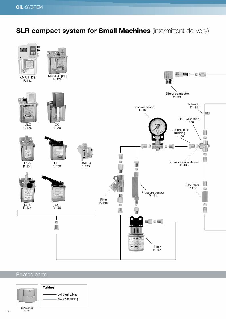
OIL-SYSTEM
Kompaktes Single Line Resistance (SLR-) System für kleine Anlagen mit diskontinuierlicher Abgabe Öl Lubrication System
●Zubehörteile
φ4 Stahlrohrleitung
φ4 Nylon-Rohrleitung
●Leitungen
LRA-AnalyseS. 197
Kompaktes Single Line Resistance (SLR-) System für kleine Anlagen mit diskontinuierlicher Abgabe Öl Lubrication System
●Zubehörteile
φ4 Stahlrohrleitung
φ4 Nylon-Rohrleitung
●Leitungen
LRA-AnalyseS. 197
AMR-III DS P. 132
MLZP. 126
L5-5P. 134
L3-3P. 134
L8P. 136
FilterP. 166
FilterP. 166
Pressure sensor P. 171
Pressure gauge P. 163
Elbow connectorP. 198
Tube clipP. 191
PJ-3 JunctionP. 138
CompressionbushingP. 188
Compression sleeveP. 188
CouplersP. 200
L20P. 136
LK-8TRP. 135
EXP. 130
MMXL-III [CE]P. 128
SLR compact system for Small Machines (intermittent delivery)
Related parts
Grease
Cleaner
S. 97
LRA
analysis
S. 226
●Zubehörteile
Pneumatic
pump for pail
S. 96
φ6 Stahlrohrleitung
φ4 Steel tubing
φ4 Nylon-Rohrleitung
Flexibler Schlauch
●Leitungen
LHL X-100cartridge Fett
S. 90
LUBE Hybrid Lubrication System (LHL) LHL Lubrication System
'
LRA analysis
P. 207
ø 4 Steel tubing
ø 4 Nylon tubing
Tubing
114

Kompaktes Single Line Resistance (SLR-) System für kleine Anlagen mit diskontinuierlicher Abgabe Öl Lubrication System
●Zubehörteile
φ4 Stahlrohrleitung
φ4 Nylon-Rohrleitung
●Leitungen
LRA-AnalyseS. 197
CSA P. 148
Flexible hoseP. 192
Compression nut P. 189
HTAP. 134
HJBP. 134
Push-in fittingP. 201
Closure plug P. 189
Sight feedP. 207
Nylon brushP. 202
PJ JunctionP. 139
Drive bushingP. 208
PJ JunctionP. 139
Elbow connectorP. 198
115

OIL-SYSTEM
●Zubehörteile
(SLR) Single Line Resistance compact system for Small to Large Machines with continuous (recirculation) delivery Öl Lubrication System
φ4 Stahlrohrleitung
φ4 Nylon-Rohrleitung
●Leitungen
LRA-AnalyseS. 226
●Zubehörteile
(SLR) Single Line Resistance compact system for Small to Large Machines with continuous (recirculation) delivery Öl Lubrication System
φ4 Stahlrohrleitung
φ4 Nylon-Rohrleitung
●Leitungen
LRA-AnalyseS. 226
ACM-II . AMI-300 . AMI-1000P. 144
Compression sleeve P. 188
Compression bushingP. 188
Pressure gauge P. 163
Elbow connector P. 198
Tube clipP. 191
PJ-3 JunctionP. 138
CouplerP. 200
Tubing P. 190
Straight adapter P. 194
FilterP. 166
AMSP. 142
SLR compact system for Small to Large Machines (continuous delivery)
Related parts
Grease
Cleaner
S. 97
LRA
analysis
S. 226
●Zubehörteile
Pneumatic
pump for pail
S. 96
φ6 Stahlrohrleitung
φ4 Steel tubing
φ4 Nylon-Rohrleitung
Flexibler Schlauch
●Leitungen
LHL X-100cartridge Fett
S. 90
LUBE Hybrid Lubrication System (LHL) LHL Lubrication System
'
LRA Analysis
P. 207
ø 4 Steel tubing
ø 4 Nylon tubing
Tubing
116

●Zubehörteile
(SLR) Single Line Resistance compact system for Small to Large Machines with continuous (recirculation) delivery Öl Lubrication System
φ4 Stahlrohrleitung
φ4 Nylon-Rohrleitung
●Leitungen
LRA-AnalyseS. 226
CSAP. 148
Flexible hoseP. 192
Compression nutP. 189
Elbow connectorP. 198
CTAP. 148
CJBP. 148
Closure plugP. 189
Sight feed P. 207
Nylon brush P. 202
Drive bushingP. 208
PJ JunctionP. 139
PJ JunctionP. 139
PJ JunctionP. 139
Push-in fitting P. 201
117

OIL-SYSTEM
OIL APPLICATION
Air and oil lubrication
Nozzle
Nozzle
Three-way
solenoid valve
P. 163
Three-way
solenoid valve
P. 163
VBP-2-G
P. 146
AMO–III DS
P. 88
Filter regulator
P. 163
Filter regulator
P. 163
Mixing block
P. 114
Mixing block
P. 114
MIX-S
P. 108
MIX-S
P. 108
118

Oil shot
Oil mist
Machine
MH-20D-A
P. 157
Dual block
P. 158
SB-N
P. 158
SB-N
P. 158
Filter regulator
P. 163
Three-way
solenoid valve
P. 163
PM-8S
P. 148
DVR
P. 106
Jet nozzle
P. 200
Flexible pipe nozzle
P. 186
Jet nozzle
P. 200
VBP
P. 146
Three-way
solenoid valve
P. 163
Filter regulator
P. 163
Filter regulator
P. 163
Three-way
solenoid valve
P. 163
Flexible pipe nozzle
P. 186
119

Related parts
OIL-SYSTEM
SLR-System
MLZ (Automatic intermittent piston pump)
Model Reference
CE
AC100V ø1
AC200V ø1
1
2
Voltage
Without
With
Blank
L
Oil level switch
MLZ CE
6min/4min48sec
15min/12min
30min/24min
60min/48min
120min/96min
A
B
C
D
E
Interval (50Hz/60Hz)
Specifications
Pump
Dischargevolume
1.5-2.5 mℓ/stroke
Dischargepressure
0.3 MPa
Motor
Voltage/current
AC100V ø1/50mA AC200V ø1/25mA (50Hz)AC100V ø1/42mA AC200V ø1/18mA (60Hz)
Output 3W Synchronous
Emergencydetection
Oil levelswitch
Contact type A contact (NO) ON at low levelContact capacity 0.5A, AC DC200V/30W smaller
Operationrating
Continuous
Working viscosityrange
30-1300 mm2/s
Reservoircapacity
0.8 ℓ
Weight 1.2 kg
Protection class IP54 (CE Approved Typ)
Model Part Number
mlZ-CE-A-1 367201
mlZ-CE-A-1L 367216
mlZ-CE-A-2 367206
mlZ-CE-A-2L 367221
mlZ-CE-B-1 367202
mlZ-CE-B-1L 367217
mlZ-CE-B-2 367207
mlZ-CE-B-2L 367222
mlZ-CE-C-1 367203
mlZ-CE-C-1L 367218
Model Part Number
mlZ-CE-C-2 367208
mlZ-CE-C-2L 367223
mlZ-CE-D-1 367204
mlZ-CE-D-1L 367219
mlZ-CE-D-2 367209
mlZ-CE-D-2L 367224
mlZ-CE-E-1 367205
mlZ-CE-E-1L 367220
mlZ-CE-E-2 367210
mlZ-CE-E-2L 367225
Adapters
P. 194
Compression parts
P. 188
Pressure gauge
P. 163
PJ junction
P. 139
Filter FX1
P. 166
Filter FY20
P. 166
Flow unit
P. 134
Reservoir
P. 170
Druckschalter PS
P. 164
Tubing
P. 190
120
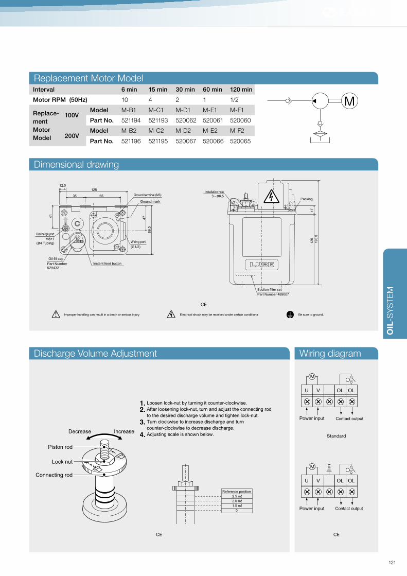
OIL
-SY
STE
M
Interval 6 min 15 min 30 min 60 min 120 min
Motor RPM (50Hz) 10 4 2 1 1/2
Replace-
ment
Motor
Model
100VModel M-B1 M-C1 M-D1 M-E1 M-F1
Part No. 521194 521193 520062 520061 520060
200VModel M-B2 M-C2 M-D2 M-E2 M-F2
Part No. 521196 521195 520067 520066 520065
M
OL OLVU
Power input Contact output
M
OL OLV
E
U
Power input Contact output
Standard
CECE
126
Installation hole
3 - ø6.5
190.5
17
Packing
125
35 65
Oil fill cap
Part Number
529432
Instant feed button
(G1/2)
Wiring port
Discharge port
M8×1
(ø4 Tubing)
89.5
47
Ground terminal (M3)
Ground mark
12.5
41
Suction filter set
Part Number 489007
126
Installation hole
3 - ø6.5
190.5
17
Packing
125
35 65
Oil fill cap
Part Number
529432
Instant feed button
(G1/2)
Wiring port
Discharge port
M8×1
(ø4 Tubing)
89.5
47
Ground terminal (M3)
Ground mark
12.5
41
Suction filter set
Part Number 489007
CE
[Oil volume adjustment knob]
Reference position
2.5 mℓ 2.0 mℓ 1.5 mℓ
0
Loosen lock-nut by turning it counter-clockwise.
After loosening lock-nut, turn and adjust the connecting rod
to the desired discharge volume and tighten lock-nut.
Turn clockwise to increase discharge and turn
counter-clockwise to decrease discharge.
Adjusting scale is shown below.
1.
2.
3.
4.
Piston rod
Connecting rod
Lock nut
Decrease Increase
Improper handling can result in a death or serious injury Electrical shock may be received under certain conditions Be sure to ground.
Replacement Motor Model
Discharge Volume Adjustment Wiring diagram
Dimensional drawing
121

Related parts
OIL-SYSTEM
SLR-System
MMXL-III (Automatic intermittent piston pump)
Model Reference
CE
AC100V ø1
AC200V ø1
1
2
Voltage
1 mℓ
2.5 mℓ
5.5 mℓ
1
2
5
Discharge volume
Without
With
Blank
L
Oil level switch
1.8 ℓ Resin reservoirs
3 ℓ Resin reservoirs
3 ℓ Metal reservoirs
4 ℓ Metal reservoirs
8 ℓ Metall-Tank
Blank
3
30
40
80
Reservoir capacity
Resin
Foot Mount
Wall Mount
Blank
F
B
Reservoir Mounting Position
Pump position-Left
Pump position-Right
L
R
Pump Position
*Metal reservoir only
3min/2min24sec
6min/4min48sec
15min/12min
30min/24min
60min/48min
120min/96min
A
B
C
D
E
F
MMXL CE
Interval (50Hz/60Hz)
*Metal reservoir only
Specifications
Pump
Dischargevolume
0.2-1.0 mℓ/stroke1.5-2.5 mℓ/stroke2.5-5.5 mℓ/stroke
Dischargepressure
0.3 MPa
Motor(Other voltagesavailable)
Power
AC100V ø1/50mA, AC200V ø1/25mA (50Hz)AC100V ø1/42mA, AC200V ø1/18mA (60Hz)
Output 3W Synchronous Motor
Emergencydetection
Oil levelswitch
Contact type A contact (NO) ON at low levelContact capacity 0.5A, AC DC200V/30W smaller
Operation rating Continuous
Workingviscosityrange
32-1300mm2/s
Reservoircapacity
1.8ℓ, 3ℓ (plastic) 3ℓ, 4ℓ, 8ℓ (sheet metal)
Weight 1.8kg (With 1.8ℓ Reservoirs)
Protection class IP54 (CE Approved Typ)
Model Part No.
MMXL-III CE-1A-1 367001
MMXL-III CE-1A-1L 367055
MMXL-III CE-1A-2 367007
MMXL-III CE-1A-2L 367061
MMXL-III CE-1B-1 367002
MMXL-III CE-1B-1L 367056
MMXL-III CE-1B-2 367008
MMXL-III CE-1B-2L 367062
MMXL-III CE-1C-1 367003
MMXL-III CE-1C-1L 367057
MMXL-III CE-1C-2 367009
MMXL-III CE-1C-2L 367063
MMXL-III CE-1D-1 367004
Model Part No.
MMXL-III CE-1D-1L 367058
MMXL-III CE-1D-2 367010
MMXL-III CE-1D-2L 367064
MMXL-III CE-1E-1 367005
MMXL-III CE-1E-1L 367059
MMXL-III CE-1E-2 367011
MMXL-III CE-1E-2L 367065
MMXL-III CE-1F-1 367006
MMXL-III CE-1F-1L 367060
MMXL-III CE-1F-2 367012
MMXL-III CE-1F-2L 367066
MMXL-III CE-2A-1 367019
MMXL-III CE-2A-1L 367073
Model Part No.
MMXL-III CE-2A-2 367025
MMXL-III CE-2A-2L 367079
MMXL-III CE-2B-1 367020
MMXL-III CE-2B-1L 367074
MMXL-III CE-2B-2 367026
MMXL-III CE-2B-2L 367080
MMXL-III CE-2C-1 367021
MMXL-III CE-2C-1L 367075
MMXL-III CE-2C-2 367027
MMXL-III CE-2C-2L 367081
MMXL-III CE-2D-1 367022
MMXL-III CE-2D-1L 367076
MMXL-IIICE-2D-2 367028
Adapters
P. 194
Compression parts
P. 188
Pressure gauge
P. 163
PJ junction
P. 139
Filter FX1
P. 166
Filter FY20
P. 166
Flow unit
P. 134
Reservoir
P. 170
Pressure switch
P. 164
Tubing
P. 190
122

OIL
-SY
STE
M
CE
Model Part No.
MMXL-III CE-2D-2L 367082
MMXL-III CE-2E-1 367023
MMXL-III CE-2E-1L 367077
MMXL-III CE-2E-2 367029
MMXL-III CE-2E-2L 367083
MMXL-III CE-2F-1 367024
MMXL-III CE-2F-1L 367078
MMXL-III CE-2F-2 367030
MMXL-III CE-2F-2L 367084
MMXL-III CE-5A-1 367037
MMXL-III CE-5A-1L 367091
MMXL-III CE-5A-2 367043
MMXL-III CE-5A-2L 367097
MMXL-III CE-5B-1 367038
MMXL-III CE-5B-1L 367092
MMXL-III CE-5B-2 367044
Model Part No.
MMXL-III CE-5B-2L 367098
MMXL-III CE-5C-1 367039
MMXL-III CE-5C-1L 367093
MMXL-III CE-5C-2 367045
MMXL-III CE-5C-2L 367099
MMXL-III CE-5D-1 367040
MMXL-III CE-5D-1L 367094
MMXL-III CE-5D-2 367046
MMXL-III CE-5D-2L 367100
MMXL-III CE-5E-1 367041
MMXL-III CE-5E-1L 367095
MMXL-III CE-5E-2 367047
MMXL-III CE-5E-2L 367101
MMXL-III CE-5F-1 367042
MMXL-III CE-5F-1L 367096
MMXL-III CE-5F-2 367048
MMXL-III CE-5F-2L 367102
Improper handling can result in a death or serious injury Electrical shock may be received under certain conditions Be sure to ground.
M
OL OLVU
Power
input
Connection
output
M
OL OLV
E
U
Power
input
Connection
output
Dimensional drawing
Installation hole
3-ø6.5
Oil fill cap
Ground mark
Wiring port
Discharge port M8×1
(ø4 Tubing)
72.5 72.5
28
14
5
G1/2
21
8
Terminal box(with cover)
12
45
6
16616
Ground terminal
Instant feed button
Suction filter set
Part Number 489010
Strainer
Part Number 521037
Part Number
529409
Packing
Interval 3 min 6 min 15 min 30 min 60 min 120 min
Motor RPM (50Hz) 20 10 4 2 1 1/2
Replace-
ment
Motor
Model
100VModel M-A1 M-B1 M-C1 M-D1 M-E1 M-F1
Part No. 521210 521194 521193 520062 520061 520060
200VModel M-A2 M-B2 M-C2 M-D2 M-E2 M-F2
Part No. 521328 521196 521195 520067 520066 520065
Replacement Motor Model Hydraulic circuit drawing
Wiring diagram Discharge Volume Adjustment
Reference position
1.0 mℓ 0.8 mℓ 0.6 mℓ 0.4 mℓ 0.2 mℓ
Reference position
2.5 mℓ 2.0 mℓ 1.5 mℓ
Reference position
5.5 mℓ 4.5 mℓ 3.5 mℓ 2.5 mℓ
[Oil volume adjustment knob]
Loosen lock-nut by turning it counter-clockwise.
After loosening lock-nut, turn and adjust the connecting rod
to the desired discharge volume and tighten lock-nut.
Turn clockwise to increase discharge and turn
counter-clockwise to decrease discharge.
Adjusting scale is shown below.
1.
2.
3.
4.
Piston rod
Connecting rod
Lock nut
Decrease Increase
123

System-Komponenten
OIL-SYSTEM
SLR-System
EX (Solenoid driven intermittent piston pump)
Related parts
Dimensional drawing
Wiring diagram Hydraulic circuit drawing
Specifications
Pump
Discharge volume
0.4 - 0.9 mℓ/Stroke (adjustable)
Discharge pressure
0.4 MPa (maximum)
Working voltage /Working current
AC100V 1 AC200V 1 50/60Hz
Workingvoltage/Workingcurrent
AC100V
50Hz 0,5A Start-up 5,8A
60Hz 0,52A Start-up 6,0A
AC200V
50Hz 0,25A Start-up 2,9A
60Hz 0,26A Start-up 3,0A
Working viscosity range
32–1300mm2/s
Reservoir capacity
1.8 ℓ
Weight 1.85 kg
0 60 50
50Hz/hour
60Hz/hour
277
173
3-φ6.5
Installationhole
Suction filter set
Part Number
489005
160
72.520
35
72.5
120
M8×1
Discharge port
Oil fill cap
Part Number
489005
(φ4 tubing)
)
)
)
)
How to change the oil discharging volume
1. Hold the connecting hexagonal rod (1), and loosen the lock-nut (3) till the spring washer (2) moves freely.2. To increase the discharging volume, roll the adjusting screw (4) according to the solid arrow. After setting the volume, fix the screw with (2) and (3).3. To decrease the discharge volume, roll the adjusting screw (4) according to the dotted arrows. After setting the volume, fix the screw with (2) and (3).4. One revolution of the adjusting screw (4) roll makes 0.06ml of discharge volume difference.
Improper handling can result in a death or serious injury Electrical shock may be received under certain conditions Be sure to ground.
277
173
3-φ6.5
Installation hole
Saugfilter set
Part Number 549005
160
72.520
35
72.5
120
M8×1
Auslassöffnung
Abdeckkappe Öleinfüllöffnung
Part Number 549005
(φ4 tubing)
(1)
(2)
(3)
(4)
Model Reference
EX
Blank
L
Oil level switch
Without
With
Without
With
Blank
C
Solenoid cover
AC100Vø1
AC200Vø1
1
2
Working voltage
Model Part Number
EX-1 102703
EX-1C 102701
EX-1L 102707
EX-1LC 102705
Model Part Number
EX-2 102702
EX-2C 102700
EX-2L 102706
EX-2LC 102704
Adapters
P. 194
Compression parts
P. 188
Pressure gauge
P. 163
PJ junction
P. 139
Filter FX1
P. 166
Filter FY20
P. 166
Flow unit
P. 134
Pressure switch
P. 164
Tubing
P. 190
124

OIL
-SY
STE
M
SLR-System
EX-5 (Solenoid driven intermittent piston pump)
Related parts
Dimensional drawing
Wiring diagram
Model Part Number
EX-5 112828
O LLow Level
(19
4)
10
4
11
91
27
90 6780
Wire pull-outopening
φ5
Suction filter setPart Number489010
DC 24VInput
SOL
Oil levelswitch Contactoutput
Improper handling can result in a death or serious injury Electrical shock may be received under certain conditions Be sure to ground.
Solenoid
Specifications
Pump
Dischargevolume
0.5 mℓ/Stroke
Dischargepressure
0.2 MPa
Working voltage/Working current
DC24V 3.0A
Energization time 2 seconds (Max. below 30 seconds)
Interval time Min. 3 Minutes (Current rate: below 1%)
Anomaly detectionOil levelswitch
Contact type (NO) ON at low level
Contact capacity 0.5A,AC DC200V/30W Smaller one
Working viscosityrange
32 – 1300mm2/s
Reservoir capacity 400 mℓ
Weight 1 kg
Hydraulic circuit drawing
Adapters
P. 194
Compression parts
P. 188
Pressure gauge
P. 163
PJ junction
P. 139
Filter FX1
P. 166
Filter FY20
P. 166
Flow unit
P. 134
Reservoir
P. 170
Pressure switch
P. 164
Tubing
P. 190
125
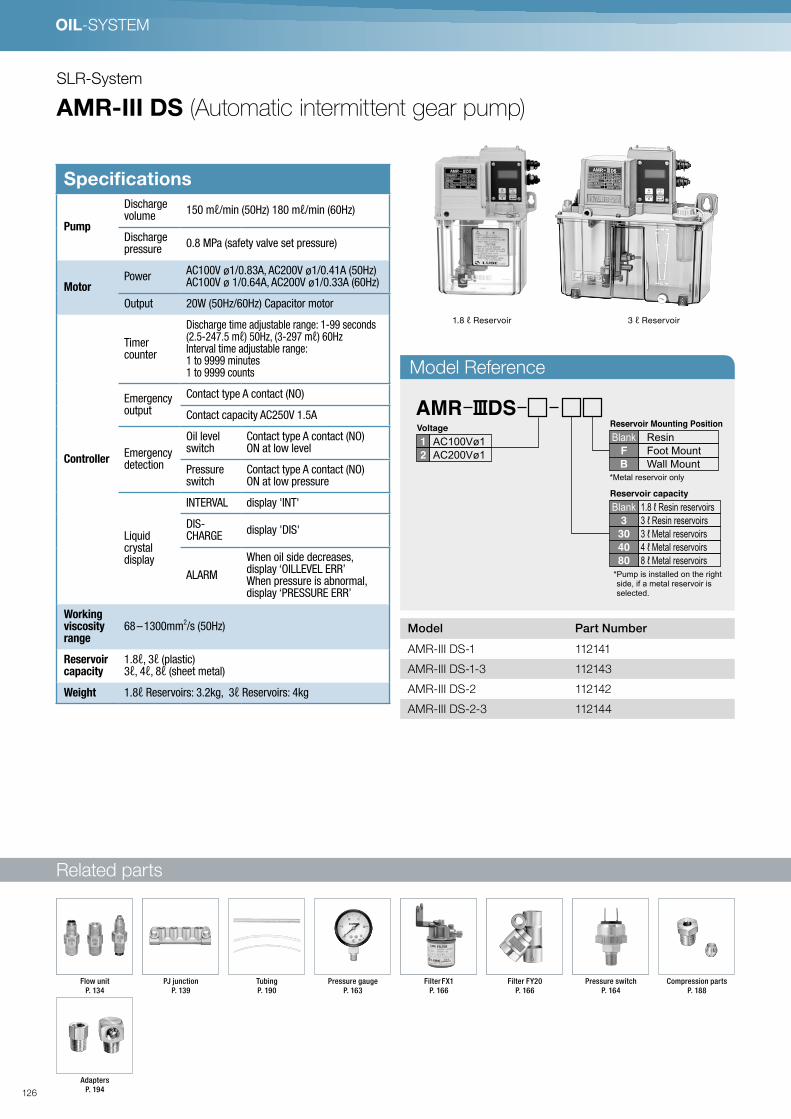
Related parts
OIL-SYSTEM
SLR-System
AMR-III DS (Automatic intermittent gear pump)
Model Reference
Model Part Number
AMR-III DS-1 112141
AMR-III DS-1-3 112143
AMR-III DS-2 112142
AMR-III DS-2-3 112144
AMR DS
AC100Vø1
AC200Vø1
1
2
Voltage
1.8 ℓ Resin reservoirs3 ℓ Resin reservoirs3 ℓ Metal reservoirs4 ℓ Metal reservoirs8 ℓ Metal reservoirs
Blank3
30
40
80
Reservoir capacity
ResinFoot MountWall Mount
BlankF
B
Reservoir Mounting Position
*Metal reservoir only
*Pump is installed on the right side, if a metal reservoir is selected.
1.8 ℓ Reservoir 3 ℓ Reservoir
Specifications
Pump
Dischargevolume
150 mℓ/min (50Hz) 180 mℓ/min (60Hz)
Dischargepressure
0.8 MPa (safety valve set pressure)
MotorPower
AC100V ø1/0.83A, AC200V ø1/0.41A (50Hz)AC100V ø 1/0.64A, AC200V ø1/0.33A (60Hz)
Output 20W (50Hz/60Hz) Capacitor motor
Controller
Timercounter
Discharge time adjustable range: 1-99 seconds(2.5-247.5 mℓ) 50Hz, (3-297 mℓ) 60HzInterval time adjustable range:1 to 9999 minutes1 to 9999 counts
Emergencyoutput
Contact type A contact (NO)
Contact capacity AC250V 1.5A
Emergencydetection
Oil levelswitch
Contact type A contact (NO)ON at low level
Pressure switch
Contact type A contact (NO)ON at low pressure
Liquidcrystaldisplay
INTERVAL display 'INT'
DIS-CHARGE
display 'DIS'
ALARM
When oil side decreases,display ‘OILLEVEL ERR’When pressure is abnormal,display ‘PRESSURE ERR’
Workingviscosityrange
68 – 1300mm2/s (50Hz)
Reservoircapacity
1.8ℓ, 3ℓ (plastic) 3ℓ, 4ℓ, 8ℓ (sheet metal)
Weight 1.8ℓ Reservoirs: 3.2kg, 3ℓ Reservoirs: 4kg
Adapters
P. 194
Compression parts
P. 188
Pressure gauge
P. 163
PJ junction
P. 139
Filter FX1
P. 166
Filter FY20
P. 166
Flow unit
P. 134
Pressure switch
P. 164
Tubing
P. 190
126
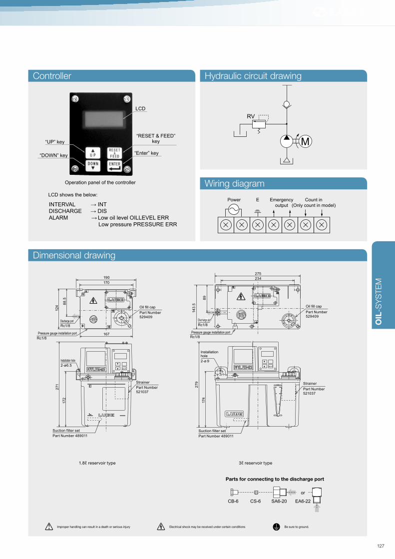
OIL
-SY
STE
M
RV
M
Power E Emergency
output
Count in
(Only count in model)
1.8ℓ reservoir type 3ℓ reservoir type
LCD shows the below:
INTERVAL → INTDISCHARGE → DISALARM → Low oil level OILLEVEL ERR
Low pressure PRESSURE ERR
LCD
“RESET & FEED”key
“Enter” key
“UP” key
“DOWN” key
Operation panel of the controller
Improper handling can result in a death or serious injury Electrical shock may be received under certain conditions Be sure to ground.
CB-6 CS-6 SA6-20 EA6-22
or
Parts for connecting to the discharge port
Dimensional drawing
Controller Hydraulic circuit drawing
Wiring diagram
271
17
2
Installation hole
Installationhole
2-ø6.5
170
167
190
12
4
88
.5
Discharge port
Rc1/8 Rc1/8
14
3.5
89
234
275
27
9
174
2-ø 9
Pressure gauge installation port
Rc1/8Rc1/8
Pressure gauge installation port
Strainer Strainer
Oil fill capOil fill cap
AuslassöffnungDischarge port
Suction filter set
Part Number 489011
Suction filter set
Part Number 489011
withP/Swith
P/S
Part Number
529409
Part Number
529409
Part Number
521037
Part Number
521037
127

Related parts
OIL-SYSTEM
SLR-System
L3 · L5 (Manually operated piston pump)
L3 L5
Dimensional drawing
Model Reference
Mo del Part No.
Discharge
volume
mℓ/Stroke
Discharge
pressure
(MPa)
Reservoir
capacity
(mℓ)
Weight
(kg)
L3-2 103031 2 0.3 220 0.34
L3-3 103030 3 0.3 220 0.34
L5-3 103051 3 0.3 400 0.4
L5-4 103052 4 0.3 400 0.4
L5-5 103053 5 0.3 400 0.4
LOW
56
70
35
13
0
97
Discharge port (M8×1)
Oil fill cap
Part number: 5490062-φ6.5
Installation hole
(22)117
19.5
(φ4 tubing)
Suction filter set
Part Number 540727
147
122
85
35
70
125 (25)
25
Rc1/8
2-φ6.5
Discharge port
Oil fill cap
Installation hole
Suction filter set
Part Number 540562
Part number: 529432
L3-3 L5-5
Reservoir
P. 170
Compression parts
P. 188
Pressure gauge
P. 163
PJ junction
P. 139
Filter FX1
P. 166
Filter FY20
P. 166
Flow unit
P. 134
Pressure switch
P. 164
Tubing
P. 190
128

OIL
-SY
STE
M
SLR-System
LK (Manually operated piston pump)
Related parts
LK-8 LK-8TR
Dimensional drawing
LK-8 LK-8TR
199 (40)
136 2820
122
11
0
Tank
installation
hole
Discharge
lever3-ø6.5
768
Oil fill cap
Part Number 529409
Drain plug
(ø4 tubing)
Discharge port (M8×1)
103 49 (40)20
13
Discharge lever
(ø4 tubing)
Suction filter set
Part Number 540562
75
56
75
56
4-ø6.5
Pump installation hole
Discharge port (M8×1)
SpecificationsDischarge volume 8 mℓ/Stroke
Discharge pressure 0.35 MPa
Weight 0.32 kg (LK), 0.75 kg (LK-8T)
Model Part Number Reservoir
LK-8 103401 —
LK-8TL 103402 ○LK-8TR 103403 ○
Compression parts
P. 188
Pressure gauge
P. 163
PJ junction
P. 139
Filter FX1
P. 166
Filter FY20
P. 166
Flow unit
P. 134
Pressure switch
P. 164
Tubing
P. 190
129

Related parts
OIL-SYSTEM
SLR-System
L8 · L20 (Manually operated piston pump)
L20-R L20-R
Dimensional drawing
SpecificationsDischarge volume 2 - 7 mℓ/Stroke (Changeable)
Discharge pressure 0.5 MPa
Working viscosity range 32 – 1300 mm2/s
Reservoir capacity 0.8 ℓ (L8), 1.8 ℓ (L20)
Weight 1.2 kg (L8), 1.8 kg (L20)
Model Part Number Lever
direction
Reservoir
capacity
L8-L 103111 Left0.8 ℓ
L8-R 103112 Right
L20-L 103211 Left 1.8 ℓ
L20-R 103212 Right
14
4
87
120
210
50 50
23
0
Discharge port
(M8×1)
Oil fill cap
Part Number 549006
3-ø6.5
Installation hole
(ø4 tubing)
20
69
Suction filter set
Part Number 489013
Installation hole
Suction filter set
72.572.5
160
231
26
12
0
95
24
8
17
3
3-φ6.5
Part Number 489005
Part Number 549005
Discharge port
(M8×1)
Oil fill cap
(ø4 tubing)
L8-L L20-L
Adapters
P. 194
Compression parts
P. 188
Pressure gauge
P. 163
PJ junction
P. 139
Filter FX1
P. 166
Filter FY20
P. 166
Flow unit
P. 134
Reservoir
P. 170
Pressure switch
P. 164
Tubing
P. 190
130

OIL
-SY
STE
MTC TD
Dimensional drawing
Dimensional drawing
Dimensional drawing
Dimensional drawing
T
30 (1.18″)
20(0
.79″
)14
(0.55
″) ø12
(0.47″
)
T1
A
T2
TG
T2
T1
15 (0
.59″)
14 (0
.55″
)20
(0.7
9″)
ø16
(0.47″)
30 (1.18″)
TK
T2
T1
29 (1
.14″
)14
(0.5
5″) ø1
2
(0.4
7 ″)
ø12
(0.47″)
15 (0
.59″)
TD
T2
T1
14 (0
.55″
)
20 (0
.79″
)
15 (0.59″)
15(0
.59″
)
ø12
(0.47″
)
T2
T1
20 (0
.79″
)
6 (0.24″)12 (0.47″)
ø16
(0.63″)
□28 (1.10″)
T2
T1
20 (0
.79″
)
6 (0.24″)12 (0.47″)
ø16
(0.63″)
□28 (1.10″)
Model Part. No. T1 T2
TC 106433 2-M8×1 Rc 1/8
TC 1864332-5/16-24
UNF1/8 NPT
Model Part No. T1 T2
TB 106432 3-M8×1 Rc 1/8
TB 1864323-5/16-24
UNF1/8 NPT
Model Part. No. T1 T2
TD 106434 2-M8×1 Rc 1/8
TD 1864342-5/16-24
UNF1/8 NPT
Model Part No. T1 T2
TH 106436 4-M8×1 Rc 1/8
TH 1864364-5/16-24
UNF1/8 NPT
Model Part. No. T1 T2
TL 106438 4-M8×1 Rc 1/8
TL 1864384-5/16-24
UNF1/8 NPT
Model Part No. T1 T2
TG 106435 3-M8×1 Rc 1/8
TG 1864354-5/16-24
UNF1/8 NPT
TA
TG
TK
TB
TH
TL
T
TB
TB
B
T2
T1
29 (1
.14″
)14
(0.5
5″) ø1
2
(0.4
7″)
30 (1.18″)
T
TC
TC
T2
T1
C
29 (1
.14″
)14
(0.55
″) ø12
(0.47 ″
)
Model Part. No. T1 T2
TK 106437 3-M8×1 Rc 1/8
TK 186437 3-5/16-24
UNF
1/8 NPT
Model Part No. T1 T2
TA 106431 2-M8×1 Rc 1/8
TA 1864312-5/16-24
UNF1/8 NPT
SLR System
TA · TB · TC · TD · TH · TK · TL (Junction header)
131

OIL-SYSTEM
SLR System
PJ (Junction)
Dimensional drawing
Model Part Number Specifications
PJ-2 106421 Two-way
Material: ZDC
Model Part Number Specifications
PJ-2F 106424 Two-way
Material: ZDC
Model Part Number Specifications
PJ-3 106420 Three-way
Material: ZDC
Model Part Number Specifications
PJ-3F 106425 Three-way
Material: ZDC
Model Part Number Specifications
PJ-4 106423 Four-way
Material: ZDC
For 4mm (5/32) tubing
12
27
12
15
2-M8×1
�12
�6.2
15
30
7
12
6.5
2-M8×1
16
�
�
12
�
12
27
12
30
�6.2
3-M8×1
4-M8×1
15
30
9
9 �12
16
�6.5
�12
30
15
7
3-M8×1 �12
16�6.5
132

OIL
-SY
STE
M
Dimensional drawing
PJ-7S
Model Part Number Specifications Size
M8×15/16-
24 UNFL1 L2
PJ-6D 106411 186411Double type
for 4 ports
47
(1.85″)34
(1.34″)
PJ-8D 106412 186412Double type
for 6 ports
63
(2.48″)50
(1.97″)
PJ-10D 106413 186413Double type
for 4 ports
79
(3.11″)66
(2.60″)
Model Part Number Specifications Size
L1 L2
PJ-12D 106414Double type
for 10 ports
82
(3.23″)94
(3.70″)
PJ-14D 106415Double type
for 12 ports
98
(3.86″)110
(4.33″)
PJ-16D 106416Double type
for 14 ports
114
(4.49″)126
(4.96″)
R3.25
L2
L1
16(0.63″)
16(0.63″)
16(0.63″)
16(0.63″)
16(0.63″)
16
.5(0
.65
″)
1 (0.04″) 1 (0.04″)
6-M8X1
(6-5/16-24UNF)
ø1
2(0
.47″
)
PJ-7S
SLR System
PJ (Junction)
16(0.63″)
16(0.63″)
1 (0.04″)1 (0.04″)
16.5
(0.65″)
R3.25
33 (1.3″)
L2
L1
6-M8X1
(6-5/16-24UNF)
φ12
(0.47″)
PJ-6D
Model Part Number Specifications Size
M8×15/16-
24 UNFL1 L2
PJ-4S 106401 186401Single type for
2 ports
47
(1.85″)34
(1.34″)
PJ-5S 106402 186402Single type for
3 ports
63
(2.48″)50
(1.97″)
PJ-6S 106403 186403Single type for
4 ports
79
(3.11″)66
(2.60″)
PJ-7S 106404 186404Single type for
5 ports
95
(3.74″)82
(3.23″)
PJ-8S 106405 186405Single type for
6 ports
111
(4.37″)98
(3.86″)
PJ-9S 106406 186406Single type for
7 ports
127
(5.00″)114
(4.49″)
PJ-10S 106407 186407Single type for
8 ports
143
(5.63″)130
(5.12″)
PJ-12S 106408 186408Single type for
10 ports
175
(6.89″)162
(6.38″)
133

OIL-SYSTEM
SLR-System (intermittent)
HSA · HJB · HTA · HTD · HTC · HTB (Flow unit)
HSA-1 HTU-02 HJB-1
Internal construction
SpecificationsNormal working pressure Under 0.8 MPa
Model No. & Flow rateFlow directionHSA
1
Inlet
Flow direction
Filter
Rod
Body
Check valve seat
Spring
Clasp
Piping layout (Example)
CP-4Closure plug
HTG
EA4-20Elbow adapter
EC1-22Elbow connector
CB-4-10Compression bushing
CS-4Compression sleeve
CS-4Compressionsleeve
HJB
CS-4Compression sleeve
CN-4Compression nut
HSA
TI-4Tube insert
CB-4-8Compressionbushing
ST-4Zø4 Steel tubing
PJ-4SJunction
NT-4ø4 Nylon tubing
T
T
J
A
H
Q
B
B
Use an appropriate sealant where mark is shown.
Mark denote tightening torque. See the tightening torque list P.234.
134

OIL
-SY
STE
M
RoHS compliant products are also available.
Please contact us for details.
Part Number Model Dimensional drawing Part Number Model Dimensional Drawing
Metric Inch Metric Inch
105501
105001
105002
105003
105004
105005
105006
105007
185501
185001
185002
185003
185004
185005
185006
185007
HSA 03
02
0
1
2
3
4
5
105513
105072
105073
105074
105075
105076
105077
105078
185513
185072
185073
185074
185075
185076
185077
185078
HTU 03
02
0
1
2
3
4
5
105502
105008
105009
105010
105011
105012
105013
105014
185502
185008
185009
185010
185011
185012
185013
185014
HJB 03
02
0
1
2
3
4
5
105503
105015
105016
105017
105018
105019
105020
105021
185503
185015
185016
185017
185018
185019
185020
185021
HTA 03
02
0
1
2
3
4
5
105507
105043
105044
105045
105046
105047
105048
105049
185507
185043
185044
185045
185046
185047
185048
185049
HTK 03
02
0
1
2
3
4
5
105504
105022
105023
105024
105025
105026
105027
105028
185504
185022
185023
185024
185025
185026
185027
185028
HTD 03
02
0
1
2
3
4
5
105508
105051
105052
105053
105054
105055
105056
105057
185508
185051
185052
185053
185054
185055
185056
185057
HTG 03
02
0
1
2
3
4
5
105505
105029
105030
105031
105032
105033
105034
105035
185505
185029
185030
185031
185032
185033
185034
185035
HTC 03
02
0
1
2
3
4
5
105509
105058
105059
105060
105061
105062
105063
105064
185509
185058
185059
185060
185061
185062
185063
185064
HTH 03
02
0
1
2
3
4
5
105506
105036
105037
105038
105039
105040
105041
105042
185506
185036
185037
185038
185039
185040
185041
185042
HTB 03
02
0
1
2
3
4
5
105510
105065
105066
105067
105068
105069
105070
105071
185510
185065
185066
185067
185068
185069
185070
185071
HTL 03
02
0
1
2
3
4
5
25 (0.98″)
HEX10(0.39″)
M8X1(5/16-24)
R1/8(1/8NPT)
29.5 (1.16″)
HEX10(0.39″)
M8X1(5/16-24)
M8X1(5/16-24)
TA
38 (1.5″)
30 (
1.1
8″)
2-M8X1(2-5/16-24)
R1/8(1/8NPT)
47 (1.85″)
TD
15
(0.59″)
2-M8X1(2-5/16-24)
R1/8(1/8NPT)
47 (1.85″)
TC
15
(0.59″)
2-M8X1(2-5/16-24)
R1/8(1/8NPT)
TB
46 (1.81″)
30 (
1.1
8″)
3-M8X1(3-5/16-24)
R1/8(1/8NPT)
23 (0.91″)
HEX10(0.39″)
R1/8(1/8NPT)
R1/8(1/8NPT)
TK
47 (1.85″)
15
(1.8
5″)
3-M8X1(3-5/16-24)
R1/8(1/8NPT)
TG
38 (1.5″)
30 (
1.1
8″)
3-M8X1(3-5/16-24)
R1/8(1/8NPT)
□28 (1.1″)
39 (1.54″)
4-M8X1(4-5/16-24)
R1/8(1/8NPT)
47
□28
14
4-M8X1(4-5/16-24)
R1/8(1/8NPT)
135

Related parts
OIL-SYSTEM
SLR-System (continuous)
AMS (Automatic small discharge volume gear pump)
Model Reference
SpecificationsAMS-1, AMS-3
PumpDischargevolume
AMS-1: 1.25 mℓ/min (50Hz), 1.5 mℓ/min (60Hz)AMS-3 : 2.5 mℓ/min (50Hz), 3 mℓ/min (60Hz)AMS-6 : 5 mℓ/min (50Hz), 6 mℓ/min (60Hz)
Dischargepressure
0.8 MPa (safety valve setting)
Motor(Othervoltagesavailable)
Power
AC100V ø1/50mA AC200V ø1/25mA (50Hz)AC100V ø1/42mA AC200V ø1/18mA (60Hz)AC100V ø1/25mA (50Hz) AC200V ø1/18mA (60Hz)
Output 3W Synchronous Motor
Emergencydetection
Oil levelswitch
Contact type A contact (NO) ON at low levelContact capacity 0.5A,AC DC200V/30W smaller
Operation rate
Continuous
Working viscosityrange
32-1300 mm2/s
Reservoircapacity
1.8ℓ, 3ℓ (plastic) 3ℓ, 4ℓ, 8ℓ (sheet metal)
Weight 1.8 kg
Model Part Number
AMS-1-1 102401
AMS-1-1L 102403
AMS-1-2 102402
AMS-1-2L 102404
AMS-15-1 102416
AMS-15-1L 102418
AMS-15-2 102417
AMS-15-2L 102419
Model Part Number
AMS-3-1 102405
AMS-3-1L 102407
AMS-3-2 102406
AMS-3-2L 102408
AMS-6-1 102489
AMS-6-1L 112094
AMS-6-2 102490
AMS-6-2L 112095
Without
With
Blank
L
AC100V ø1
AC200V ø1
1
2
Voltage
1.25/1.5mℓ/min2.5/3mℓ/min5/6mℓ/min15/18mℓ/min
1
3
6
15
Oil level switch
AMS
Discharge volume (50Hz / 60Hz)
1.8ℓ Resin reservoirs3ℓ Resin reservoirs3ℓ Metal reservoirs4ℓ Metal reservoirs8ℓ Metal reservoirs
Blank
3
30
40
80
Reservoir capacity
Resin reservoirsFoot MountWall Mount
Blank
F
B
Reservoir Mounting Position
Pump position-LeftPump Position-Right
*Except 1.8ℓ Resin reservoir
*Metal reservoir only
L
R
Pump Position
Metal reservoir
P. 174
Adapters
P. 194
Compression parts
P. 188
Pressure gauge
P. 163
PJ junction
P. 139
Control unit
P. 142
Filter FX1
P. 166
Filter FY20
P. 166
Pressure switch
P. 164
Tubing
P. 190
136

OIL
-SY
STE
M
Dimensional drawing
Hydraulic circuit drawing
Wiring diagram
72.5 72.5
10
3-φ6.5
16025
30
120
φ4 Leitungenø4 Tubing
Ölmenge adjusting screw
Oil volume adjusting screw
Oil fill cap
267
173
Wiring port
Suction filterPart Number 500324
Part Number549005
Auslassöffnung(M8×1)Discharge port(M8×1)
20
3
14
83
5
72.5 72.5
25
3-ø6.5
Installation hole
160
12
0
Wiring portDischargeport (M8×1)
Oil volumeadjusting screw
Oil fill cap
(ø4 Tubing)
25
30
Suction filter
Part Number 500324
Part Number
549005
AMS-1, 3 AMS-15
AMS-1, 3, 6 AMS-15
Improper handling can result in a death or serious injury Electrical shock may be received under certain conditions Be sure to ground.
SpecificationsAMS-15
PumpDischargevolume
15 mℓ/min (50Hz) 18 mℓ/min (60Hz)
Dischargepressure
0.8 MPa (safety valve setting)
Motor(Other voltagesavailable)
Power AC100V ø1/0,25A (50Hz/60Hz) 200V ø1
Output 5.0W Accessory - Condensor3.0μF
Gear Head Speed Reduction Ratio: 1/25
Working viscosityrange
32-1300mm2/s
Reservoir capacity 1.8ℓ, 3ℓ (plastic) 3ℓ, 4ℓ, 8ℓ (sheet metal)
Weight 2.3 kg
Pump Part No. Voltage Replacement Motor Model
AMS-1521194 100V M-B1
521196 200V M-B2
AMS-3521194 100V M-B1
521196 200V M-B2
AMS-6521210 100V M-A1
521328 200V M-A2
RV
MOL SW
Option
M
1 2
C
Power input
3OL OLVU
Power input Contact output
137

Related parts
OIL-SYSTEM
SLR System (continuous)
ACM-II · AMI-300 · AMI-1000 (Motor driven gear pump)
Model Reference
Reservoir Mounting Position
*AC200V φ3 Needle valve availableonly with AMI-1000
ACMAMI 300AMI 1000
AC100V ø1AC200V ø3AC200V ø3With needle valve
Voltage
3ℓ Metal reservoirs4ℓ Metal reservoirs8ℓ Metal reservoirs
30
40
80
Reservoir capacity
Resin reservoirsFoot mountWall mount
BlankF
B
Reservoir Mounting Position
Pump position-LeftPump Position-Right
L
R
WithoutWith
BlankL
Oil level switch
1
2
3
Specifications ACM-II AMI-300 AMI-1000
PumpDischarge volume
60 mℓ/min (50Hz)70 mℓ/min (60Hz)
300 mℓ/min (50Hz)330 mℓ/min (60Hz)
1000 mℓ/min (50Hz)1100 mℓ/min (60Hz)
Discharge pressure
0.8 MPa(safety valve setting)
0.5 MPa(safety valve setting)
1.2 MPa(safety valve setting)
Motor(Other voltagesavailable)
Voltage / CurrentAC100V ø1/0.51/0.52A(Kondensator: 8µF)AC200V ø3/0.23/0.21A
AC100V ø1/0.76/0.74A(Kondensator: 11µF)AC200V ø3/0.32A/0.3A
AC100V ø1/1.2/1.19A(Kondensator: 20µF)AC200V ø3/0.50/0.43A
Output25WInduction motor
40WInduction motor
60WInduction motor
Operation rate Continuous
Working viscosity range 32–1300 mm2/s 65–1300 mm2/s
Reservoir capacity 2ℓ, 3ℓ, 4ℓ, 8ℓ (sheet metal)
Weight 4.0 kg 4.4 kg 7.1 kg
OtherMotor rotary direction:Counter-clockwise
Motor rotary direction:Clockwise
Motor rotary direction:Counter-clockwise
External fuse100V/1A200V/0.5A
100V/2A200V/1A
100V/3A200V/1A
AMI-300 AMI-1000ACM-II
Model Part Number
ACM-II -1 102484
ACM-II -2 102486
Metal reservoir
P. 174
Adapters
P. 194
Compression parts
P. 188
Pressure gauge
P. 163
PJ junction
P. 139
Control unit
P. 142
Filter FX1
P. 166
Filter FY20
P. 166
Pressure switch
P. 164
Tubing
P. 190
138
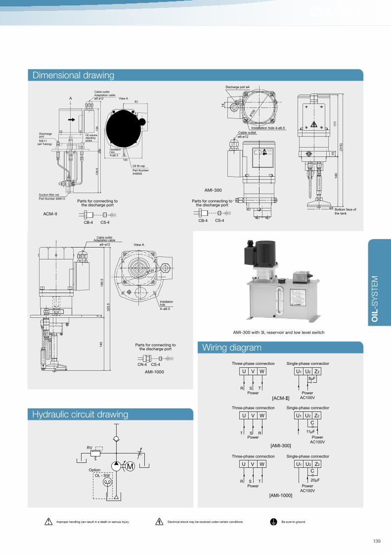
OIL
-SY
STE
M
Dimensional drawing
Hydraulic circuit drawing
Wiring diagram
Three-phase connection Single-phase connection
Power
AC100V
Power
AC100V
Power
AC100V
Power
[ACM- ]
[AMI-300]
[AMI-1000]
Three-phase connection Single-phase connection
Power
Three-phase connection Single-phase connection
Power
U V W
RST
U1
8μF
U2 Z2U V W
R S T
C
20μF
U1 U2 Z2U V W
R S T
C
11μF
U1 U2 Z2
AMI-300 with 3L reservoir and low level switch
RV
MOL SW
Option
ø6~ø12
325.5
140
185.5
7
φ120
Cable outletAdaptation cable
View A
Installationhole
4–ø6.5
Cable outlet
Adaptation cable
ø6-ø12 View AA↓
φ120
83
130
139
5
298
135.5
Oil volumeadjustingscrewM8×1
Dischargeport
(ø4 Tubing)
4-φ6.3
Installationhole
Oil fill cap
Suction filter set
Part Number 489012
Part Number
549005
14
17
11
51
40
6
(31
5)
Discharge port ø4
φ100
ø6-ø12
Cable outlet
Bottom face of
the tank
Installation hole 4-ø6.5
AMI-300
ACM-II
AMI-1000
Improper handling can result in a death or serious injury Electrical shock may be received under certain conditions Be sure to ground.
Parts for connecting tothe discharge port
CB-4 CS-4
Parts for connecting tothe discharge port
CB-4 CS-4
Parts for connecting tothe discharge port
CN-6 CS-6CN-4 CS-4
139

Related parts
OIL-SYSTEM
SLR System (continuous)
AM (Automatic intermittent gear pump)
Model Reference
Specifications
Pump
Dischargevolume
50 ml/min(50HZ), 60 ml/min(60HZ)
10 - 300m/hour Changeable by adjusting the cam
Dischargepressure
0.8MPa (Safety valve set pressure)
Motor(Capableof copingwith adifferentvoltage)
Workingvoltage/Workingcurrent
AC100V ø1 25W: 0.51/0.52A
AC200V ø3 25W: 0.23/0.21A
OutputInduction generator B-class, 4P 25W
Oil level switch Optional on the reservoirs flange
Rated operation Continuous
Working viscosity range 32 – 1300 mm2/s
Weight AM: 5.4 kg ADM: 5.9 kg
OthersDirection of rotation: CCW
Condenser 100V 8μF
External fuse 100V/1A 200V/0.5AAM
AM
AC100V ø1
AC200V ø3
1
2
Voltage Without
With
Blank
L
Oil level switch
2ℓ Metal reservoirs3ℓ Metal reservoirs4ℓ Metal reservoirs8ℓ Metal reservoirs
20
30
40
80
Tank capacityFoot mount
Wall mount
F
B
Reservoir mounting position
Pump position-leftPump position-right
L
R
Pump position
*Except 2L metal reservoir
*Except 2L metal reservoir
Cam
No.Interval time
Discharge
volume per a
cycle (ml)
Discharge
volume per
hour (ml)
Required time to
discharge 1L
50Hz 60Hz 50Hz 60Hz 50Hz 60Hz
1 30 min 25 min 5 8 10 125 hour 100 hour
2 30 min 25 min 10 15 20 66 hour 40 min 50 hour
3 30 min 25 min 15 23 30 43 hour 28 min 35 hour
4 30 min 25 min 20 30 40 33 hour 20 min 25 hour
5 7 min 30 sec 6 min 15 sec 10 75 100 13 hour 20 min 10 hour
6 7 min 30 sec 6 min 15 sec 15 113 150 8 hour 50 min 7 hour
7 7 min 30 sec 6 min 15 sec 20 150 200 6 hour 40 min 5 hour
8 7 min 30 sec 6 min 15 sec 30 225 300 4 hour 26 min 3 hour
Model Part Number
AM-1 102054
AM-2 102050
Metal reservoir
P. 174
Adapters
P. 194
Compression parts
P. 188
Pressure gauge
P. 163
PJ junction
P. 139
Filter FX1
P. 166
Filter FY20
P. 166
Pressure switch
P. 164
Tubing
P. 190
Flow unit
P. 134
140

OIL
-SY
STE
M
Dimensional drawing
Hydraulic circuit drawing Wiring diagram
13
91
34
29
72
97
13
91
34
Discharge port
M8×1
Installation hole
4-ø6.3
(ø4a tubing)
Detail drawing viewing from A
Detail drawing viewing from A
A↓
Discharge port (Intermittent)
Installation hole
M8×1(ø4 tubing) Discharge port (Continuous)
M8×1 (ø4 tubing)
4-ø6.3
Suction filter set Part Number 489001
Suction filter set Part Number 489001
Oil fill cap
Part Number 549005
Oil fill cap
Part Number 549005
φ120φ120
Direction of rotation
A↓
RV
M
RV
M
RV
OL SW OL SW
Optional Optional
Three phase power supply
U V W
Power
Single phase power supply
Power
U1
C
8μF
U2 Z2
ADM
AM
Improper handling can result in a death or serious injury Electrical shock may be received under certain conditions Be sure to ground.
141

OIL-SYSTEM
SLR System (continuous)
CSA · CJB · CTA · CTD · CTC · CTB (Control unit)
Internal construction
Inlet
Taper pin
Helical restrictor
Body
Clasp
Model No. & Flow rateFlow directionCSA
04
CSA-04 CTU-2 CJB-04
Specifications
Normal working pressure Under 0.8 MPa
CP-4Closure plug
EA4-20Elbow adapter
EC1-22Elbow connector
CS-4Compressionsleeve
CS-4Compressionsleeve
CJB
CB-4-10Compressionbushing
CN-4Compression nut
CB-4-10Compression bushing
CSA
TI-4Tube insert
NT-4ø4 Nylon-Überwurfschraube
PJ-4SJunction
CS-4Compressionsleeve
CTG
ST-4Zø4 Steel tubing
T
T
J
A
H
Q
B
B
Tubing connection (Example)
Use an appropriate sealant where mark is shown.
Mark denote tightening torque. See the tightening torque list P.234.
142

OIL
-SY
STE
M
Part No. Mo-
del
Dimensional drawing Part No. Mo-
del
Dimensional drawing
Metric Inch Metric Inch
105201
105202
105203
105204
105205
105206
105207
105208
105209
105210
185201
185202
185203
185204
185205
185206
185207
185208
185209
185210
CSA
05
04
03
02
0
1
2
3
4
5
105321
105322
105323
105324
105325
105326
105327
105328
105329
105330
185321
185322
185323
185324
185325
185326
185327
185328
185329
185330
CTU
05
04
03
02
0
1
2
3
4
5
105211
105212
105213
105214
105215
105216
105217
105218
105219
105220
185211
185212
185213
185214
185215
185216
185217
185218
185219
185220
CJB
05
04
03
02
0
1
2
3
4
5
105221
105222
105223
105224
105225
105226
105227
105228
105229
105230
185221
185222
185223
185224
185225
185226
185227
185228
185229
185230
CTA
05
04
03
02
0
1
2
3
4
5
105261
105262
105263
105264
105265
105266
105267
105268
105269
105270
185261
185262
185263
185264
185265
185266
185267
185268
185269
185270
CTK
05
04
03
02
0
1
2
3
4
5
105231
105232
105233
105234
105235
105236
105237
105238
105239
105240
185231
185232
185233
185234
185235
185236
185237
185238
185239
185240
CTD
05
04
03
02
0
1
2
3
4
5
105271
105272
105273
105274
105275
105276
105277
105278
105279
105280
185271
185272
185273
185274
185275
185276
185277
185278
185279
185280
CTG
05
04
03
02
0
1
2
3
4
5
105241
105242
105243
105244
105245
105246
105247
105248
105249
105250
185241
185242
185243
185244
185245
185246
185247
185248
185249
185250
CTC
05
04
03
02
0
1
2
3
4
5
105281
105282
105283
105284
105285
105286
105287
105288
105289
105290
185281
185282
185283
185284
185285
185286
185287
185288
185289
185290
CTH
05
04
03
02
0
1
2
3
4
5
105251
105252
105253
105254
105255
105256
105257
105258
105259
105260
185251
185252
185253
185254
185255
185256
185257
185258
185259
185260
CTB
05
04
03
02
0
1
2
3
4
5
105291
105292
105293
105294
105295
105296
105297
105298
105299
105300
185291
185292
185293
185294
185295
185296
185297
185298
185299
185300
CTL
05
04
03
02
0
1
2
3
4
5
25 (0.98″)
HEX10(0.39″)
M8X1(5/16-24)
R1/8(1/8NPT)
29.5 (1.16″)
HEX10(0.39″)
M8X1(5/16-24)
M8X1(5/16-24)
TA
38 (1.5″)
30(1
.18″)
2-M8X1(2-5/16-24)
R1/8(1/8NPT)
38 (1.5″)
TD
15
(0.98″)
2-M8X1(2-5/16-24)
R1/8(1/8NPT)
47 (1.85″)
TC
15
(0.59″)
2-M8X1(2-5/16-24)
R1/8(1/8NPT)
TB
46 (1.81″)
30
(1.1
8″)
3-M8X1(3-5/16-24)
R1/8(1/8NPT)
23 (0.91″)
HEX10(0.39″)
R1/8(1/8NPT)
R1/8(1/8NPT)
TK
47 (0.98″)
15
(0.9
8″)
3-M8X1(3-5/16-24)
R1/8(1/8NPT)
38 (0.98″)
TG
30 (0.98″)
3-M8X1(3-5/16-24)
R1/8(1/8NPT)
CT
U05
39 (1.54″)
□28 (1.1″)4-M8X1(4-5/16-24)
R1/8(1/8NPT)
47 (1.85″)
28 (1.1″)
14 (0.55″)
4-M8X1(4-5/16-24)
R1/8(1/8NPT)
143

144

➔ PNEUMATICPumpsVBP P. 146
PM-8S P. 148
System ComponentsSpray nozzle P. 156
Mixing block P. 150
Spray cooling system P. 151
Accessories P. <?>
LUBFIT Oil Series
LF-53 · LF-55 · LF-60 · LF-65 P. 153
145

OIL-SYSTEM
Pneumatic System
VBP (Air-driven pump for delivering small volumes of biodegradable oil)
Model Reference
VBP
Pulse generator
1.8ℓ3.0ℓ
Blank
3
Note: Max. 3 pumps for 1.8L reservoir
Max. 5 pumps for 3.0L reservoir
Number of pumps
Tank capacity
Without
With
Blank
G
ModelPart
No.
Number
of pump
unit
Generator Reservoir
1.8ℓ 3.0ℓ
VBP-1 112740 1 ○VBP-2 112741 2 ○VBP-3 112742 3 ○VBP-1-G 112746 1 ○ ○VBP-2-G 112747 2 ○ ○VBP-3-G 112748 3 ○ ○VBP-1-3 112752 1 ○
VBP-2-3 112753 2 ○
VBP-3-3 112754 3 ○VBP-4-3 112755 4 ○
VBP-5-3 112756 5 ○VBP-1-G-3 112762 1 ○ ○VBP-2-G-3 112763 2 ○ ○VBP-3-G-3 112764 3 ○ ○VBP-4-G-3 112765 4 ○ ○VBP-5-G-3 112766 5 ○ ○
133
Manual feed button
ø4 Oil discharge port ø6 Air inlet
Pulse generator
270
234
169
152
(250)
8
2-ø6.5Installationhole
Oil fill cap
Strainer
Ölmenge adjustment KnobOil volumeadjustment knob
Specifications
Discharge volume 0 - 0.07 mℓ/shot
Discharge cycle 2 shot / sec (MAX)
Effective pump ratio1 : 5 (Discharge pressure 1.5 Mpa whenair pressure 0.3 Mpadischarge volume 0.05 mℓ/shot)
Air pressure range0.3 - 0.7 MPa0.4 - 0.7 MPa (with pulse generator)
Working viscosity range
2 – 180 mm2/s
Number of pump units(Standard spec.)
1.8ℓ reservoir : 3 pumps3ℓ reservoir : 5 pumps
Reservoir capacity 1.8ℓ, 3ℓ resin reservoir (standard)
VBP-3
VBP-5-G
Dimensional drawing
146

OIL
-SY
STE
M
Dimensional drawing
Figure 1 Figure 2
0
Revolu-
tions
of knob
0 1 2 4 6 8 10 12 14
Dischage
volume
for
1 shot
0 0.005 0.01 0.02 0.03 0.04 0.05 0.06 0.07
φ11R3. 25
160 120
168
8
152
(250)
140 Manual feed buttonPulse generator
Ölmenge adjustment KnobOil volumeadjustment knob
Oil fill cap
Strainer
VBP-3-G
Position Scale Pressure of pressured air
0.3 0.4 0.5
1 * 150 130 120
2 III 3 3 3
Adjustment of VBP pulse generator
147

System-Komponenten
OIL-SYSTEM
Pneumatic System
PM-8S (Piston pump)
PM-8S
Model Reference
Hydraulic circuit drawing
Model Part No.
PM-8S 102660
PM-8S-L 102754
PM 8S
Without
With (A contact)
Blank
L
Oil level switch
*Specify the pump location (right or left) if 13L reservoir is selected.
*1
*Pump is installed on the right side, if a metal reservoir is selected.
1.8ℓ Resin reservoirs3ℓ Resin reservoirs3ℓ Metal reservoirs4ℓ Metal reservoirs8ℓ Metal reservoirs
Blank
3
30
40
80
Reservoir capacity
1.8ℓ ResinFoot MountWall Mount
Blank
F
B
Reservoir Mounting Position
*Metal reservoir only
**Except 1.8ℓ reservoir.
Pump position-Left
Pump position-Right
Pump Position
L
R
Related parts
SpecificationsPump ratio 1:5 (under air pressure of 0.5 MPa)
Dischargevolume
8 mℓ/shot (6 mℓ, 7 mℓ: available by special order)
Workingviscosity
Spray method: Oil shot 10-100 cStOil/air 10-1800 cStContact us when a special lubricant is required.
Air pressure vs.air consumption
0.4 MPa - 0.27 Nl/shot; 0.5 MPa - 0.3 Nl/shotTotal valve discharge: Approx. 5 mℓ
System capacity When using 0.5 mℓ valve, up to 10 points.
Reservoircapacity
1.8ℓ, 3ℓ resin reservoir (standard)3ℓ resin reservoir, 3ℓ, 4ℓ, 81 metal reservoir (optional)
Options
3-way solenoidvalve
Voltage: AC100V, AC200V,DC24V
Oil level switch (NO) ON at low level
Contact capacityAC, DC200V 30W or resistanceload 0.5A, whichever smaller
Weight 1.8ℓ reservoir: 1.2 kg, 8ℓ reservoir: 11.0 kg
NO
NC
COM
Air source
Regulator
Air pressure gauge
Dischargepressure gauge
Three-way solenoid valve
Release mechanism Suction filter
Pneumatic pump
Discharge port
F-3D Filter
P. 166
Metal reservoirs
P. 174
Adapters
P. 194
Compression parts
P. 188
Pressure gauge
P. 163
MIX-S Metering valve
P. 108
Tubing
P. 190
MO2(C) Metering valve
P. 101
MO Metering valve
P. 100
MOS Metering valve
P. 102
MB Metering valve
P. 104
PV Junction
P. 97
For MO Valve
PVS Junction
P. 98
For MOS Valve
Flexible pipe nozzle
P. 192
DVR Metering valve
P. 106
JVPA Junction
P. 102
For MO2(C) Valve
148

OIL
-SY
STE
M
Dimensional drawing
[PM-8S]
Rc1/8
Discharge port
M10×1
72.5
30
27
72.53-ø 6.5
Installation hole
Air inlet
12
0
160
18
4
17
4
149

Related parts
OIL-SYSTEM
Pneumatic System
VOA (Flexible Spray nozzle for VBP-Pump)
MIB (Mixing block for VBP-Pump)
Dimensional drawing
FDM
Model Part Number
VOA-365 112786
Model Part Number
MIB 559271
Model Part Number Discharge volume (ml/shot)
FDM-3 225022 0.03
FDM-5 225023 0.05
FDM-10 225024 0.1
FDM-20 225025 0.2
FDM-30 225026 0.3
FDM-50 225027 0.5
20
(365)
Air inlet
ø6 Nylon tubing
2-ø5.5
Oil inlet
M8×1
35
2-ø4.5
M8X1
M8X1
M8X1
25
13
22
11
6
15
30
(50)Discharging port
Oil inlet
Air inlet
FDM (Flexible pipe nozzle with metering valve)
Dimensional drawing
19
12
34
2-ø4.5
Rc1/8 280
Sealing washer Metering valve
Jet nozzle
PM Pump
P. 148
VBP Pump
P. 146
150

OIL
-SY
STE
M
Specifications
Air input pressure 0.7 MPa (Maximum)
Normal working air pressure 0.1 - 0.3 MPa
Working viscosity range 2 – 100 mm2/s
Reservoir capacity 2ℓ
Filter (At the oil discharge port) Filtration accuracy: 40μ
Number of available spray nozzle 1 to 4 pieces
Material of the reservoirs A5052TD-H34
Weight 3.3 kg
OptionalOil levelswitch
Contact capacity AC . DC200V 0.5A 30W
Contact type NO
SolenoidTwo-way/Three-wayAC100V / AC200V DC24V
MH-20D-A
Model Part Number Oil level switch
MH-20D-A 222138 Without
MH-20D-A-L 222195 With
1. In order to stop the oil flow, use a three-way solenoid valve on the air supply.
By stopping air flow quickly, oil flow will be stopped well.
Filterregulator
Three-waysolenoid valve
Filterregulator
Three-waysolenoid valve
Filterregulator
Three-waysolenoid valve
MH-20D-A
MH-20D-A
MH-20D-A
Air passage
Oil passage
Oil passage
Two-waysolenoid valve
Two-waysolenoid valve
Air passage
Oil passage
Air passage
3. Instead of spray nozzle, control units can be used, so this system becomes oil pump
run by air.
Valves(Control unit)
Spray nozzle
Spray nozzle
2-A. By using each pieces of two-way solenoid valve for air hose and oil hose, switching
oil fog On and OFF can be done quickly. By switching the solenoid valve for air hose
OFF, only oil can be discharged from the spray nozzle.
2-B. If the oil fog is not used, plug the air hose instead of using the two-way solenoid
valve.
Dimensional drawing48
207
299
190
46
2-ø7
ø6
Filter(At the oildischarge port)
Drain plug G1/8
Oil fill capA
14812876
Air inputRc1/8
Air outputRc1/8
Dischargeport
74
2
148
(164)
Detail drawing viewing from A
Öl discharge portRc1/8Oil discharge portRc1/8
Pneumatic System
MH-20D-A (Spray cooling system)
151

OIL-SYSTEM
Pneumatic System
Accessories for MH-20D-A pump
Dimensional drawing (Flexible spray nozzle)
Dimensional drawing (Block type spray nozzle)
Dimensional drawing (Dual hose)
Dimensional drawing (Dual block)
Model Part Number L
DH-500 226710 500
DH-1000 226711 1000
DH-1500 226712 1500
DH-2000 226713 2000
DH-2500 226714 2500
Model Part No. L1 L2 Number of nozzle installation
DB-3 226403 38 25 3 way
DB-5 226405 76 63 5 way
DB-6 226406 94 81 6 way
Model Part Number Top
SB-N 225001 Nozzle shape
SB-R 225002 R1/8
Model Part Number L
SJ-265 225011 265
SJ-410 225012 410
SJ-500 225013 500
SJ-600 225016 60017
Volume adjusting
screw
Air input Rc1/8
Oil input M8×1
5.5
16.5
25
42
Jet tip2-φ6.5
L
[SB-N]
[SJ-265]
[SB-R] [Dual hose][DB-3]
2-ø5.52-ø5.5
Rc1/8
16
.5
68
42
10
17 5.5
5 MAX
Oil input
M8×1Air input
R1/8
16
.5
76 10
17 5.5
5 MAX
Oil input
M8×1Air input
Rc1/8
[SB-N] [SB-R]
R1/8
Compression sleeve
Compression bushing
L
30
15.5
6.5
6-Rc1/8
30
16
8
6-M8×1
18 18 18
2-ø7
L1
L2
152

OIL
-SY
STE
M
Model Capacity
LF-53-5
5 ℓLF-55-5
LF-60-5
LF-65-5
LF-53-20
20 ℓLF-55-20
LF-60-20
LF-65-20
Pneumatic System
LF 53 · LF 55 · LF 60 · LF 65 (LUBFIT Oil Series)
[LF-55-20]
[LF-55-5]
[LF-53-20]
[LF-53-5]
[LF-60-20]
[LF-60-5]
[LF-65-20]
[LF-65-5]
SpecificationsLF-53 LF-55 LF-60 LF-65
Color Colorlessand trans-parentliquid
Colorlessand trans-parentliquid
Colorlessand trans-parentliquid
Colorlessand trans-parentliquid
Density (g/cm3) 0.76 0.79 0.79 0.90
Viscosity (mm
2/s, 40°C)
1.5 2.2 2.2 27
Flash point (°C) > 70° > 80° > 80° > 150°
Copper Corro-sion (100°C/h)
No changeof color
No changeof color
No changeof color
No changeof color
* Numeric value is a measured one. It is not the standard one.
153

154

ACCESSORIESProximity sensor for series progressive valve P. 156
Solenoid valve P. 157
Oil level switch P. 158
Filter / Strainer P. 160
Eliminator P. 162
Pressure gauge P. 163
PS (Pressure switch) P. 164
SPS (Pressure switch) P. 165
LUDO-sensor P. 166
OA- I (Air-Oil sensor) P. 168
155

OIL-SYSTEM
Dimensional drawing
Accessories
Proximity sensor for series progressive valve
SDM-72 (Steel dust meter)
SpecificationsMeasurementprinciple
Magnetic balance type electromagnetic
Substancemeasured
Steel dust concentration in grease
Measurement range 0 to 19999 ppm (Wt)
Zero adjustment Automatic adjustment
Amount of sample 1.5 ml
Power 4× AA (R6) alkaline dry cells or AC adaptor
Battery life Up to 30 hours by alkaline cells
Operatingtemperature
0 to 40 °C
Dimensions W 84 × H 190 × D 40mm
Weight Approx. 500g (including batteries)
Model Part Number
SDM-72 —
Electrically monitors the movement of the indicator pin of progressive valve.
Proximity sensor can be used to monitor for a Progressive Valve or system failure,
and can also be used to monitor pump discharge time.
The New Cosmos SDM-72 steel dust meter employs a magnetic balance type
electromagnet induction method for measuring.
The SDM-72 is a useful and simple diagnostic tool for inspecting the abrasion status
of bearings and gears.
ø21
174
10
33
38
2-clamping nut
9
M12
Toothed washer
Indicator
SpecificationsE2E-X2E1 E2F-X2E1 E2F-X2Y1
Power voltage DC10-24V AC24-240V
Workingvoltage range
DC10-40V DC10-30V AC20-264V
Output Form DC 3 leads NPN AC 2 leads
DetectingDistance
2 mm ± 10%
Setting Distance 0 -1.6 mm
Detecting Object Iron 12×1 mm
Protection class IEC Standards IP67 IEC Standards IP68
Model Part Number
E2E-X2E1 733225
E2F-X2E1 730797
E2F-X2Y1 730721
156

OIL
-SY
STE
M
AB · VX (Solenoid valve)
AW-20 (Filter regulator)
Model Part Number
AW20-01BG 229570
Model Part No. Specifi-
cations
Working
voltage
Maximum
working
pressure
difference
AB31013 229439 Two-way AC100V 0.7 MPa
AB31013 229440 AC200V
AB31013 229438 DC24V
VX3114-
1G
229548 Three-way AC100V
VX3114-
2G
229549 AC200V
VX3114-
5G
229550 DC24V
2-ø5.3
Installation hole
Bracket11
46
36
40
20 23 290±10
2-Rc1/8 (PT)P
Connectiondiameter
18
30
948 (
55)
10
68 (
78)
Two-way
30
20
Installation hole
14
.5
19
6
46.5
74.5
NO
P K
anal
2-ø5.3
29
18
20 22.5
20 23 290±10
Bracket
3-Rc1/8(PT)P
Three-way
Dimensional drawing
Dimensional drawing
Connection diameter Rc1/8
M5×0.8
Pressure gauge
164.5
157

OIL-SYSTEM
Accessories
W-105 · WL · WTL (Oil level switch)
Float
Model Part Number Terminal box
WL-100-U30BS 109221
—
WL-105-U32BS 109222
WL-120-U50BS 109223
WL-150-U35BS 109224
WL-150-U50BS 109225
WL-160-U80BS 109226
WL-190-U80BS 109227
WL-210-U50BS 109228
WTL-100-U30BS 109271
○
WTL-105-U32BS 109272
WTL-120-U50BS 109273
WTL-150-U35BS 109274
WTL-150-U50BS 109275
WTL-160-U80BS 109276
WTL-190-U80BS 109277
WTL-210-U50BS 109278
W-105BW-105-02
W L U BS
Terminal box
Contact point for lower limitOperating position unit / mm
Contact point for upper limitOperating position unit / mm
Contact point for lower limitOperating position unit / mm
Contact point for upper limitOperating position unit / mm
Type of contactpoint for lower limit
Type of contactpoint for upper limit
Type of contactpoint for lower limit
Type of contactpoint for upper limit
Without marking
T
Non existence
Existence
Terminal box
Without marking
T
Non existence
Existence
Without marking NO B NC
S Single float (1 float)
●1 Float
●2 Float
W L U
Without marking
B
NO
NC
NO
NC
Without marking
B
Specifications
Contact type(NO) On at low level(NC) Off at low level
Contact capacity 0.5A, AC DC200V/30W smaller
Working temperature range
−10 - 80°C(limited to liquid in nonfreezing condition)
Working liguid specific gravity
over 0.7
Max. pressure 0.1 MPa
ModelPart
No.
Contact
typeSpecification
W-105-02 109704 NO Without terminal
box Cord length 20 cmW-105-02 (B) 109705 NC
W-105B 109706 NOWith terminal box
W-105B (B) 109707 NC
Example for using oil level switch
Lead switch
Float
Magnet
100V or 200V
Output terminal
Buzzer or lamp
Power relay
158

OIL
-SY
STE
M
Dimensional drawing
Float Positions
30
φ50
66
□90
94□
φ60
60
6P
φ22
60
2-ø6.514
5
±2
30
Lower limitposition
Upper limitposition
Upper limitposition
Wiring port Terminal
Terminal
Wiring port3
0
φ50
30
1 Float2 Float
10
11
4
14
7
M8×1
20
0
5
ø18
ON
7.7
W-105-02 WTL
White Red Black
Example : 2 floatExample : 1 float
WL105-U35
White Red Black
WL105B-U35
White Red Black
Upper limitposition
Lower limitposition
Untere Füllmengenposition Untere FüllmengenpositionLower limit position Lower limit position
Upper limitposition
Upper limitposition
WL105-U35BS
35
10
5
ON
ON ON
ONON
ON
35
10
5
35
10
5
159

OIL-SYSTEM
Accessories
FXE · F3E · FYE · RF (Filter / Strainer)
FX1-4FY20
RF-250 F3-6-125
Model Part No.Connecting
port
Normal
working
pressure
(MPa)
Pressure
Loss
Filtration
rating
Additional
parts
FX1-4 109311 M8×1 1.0 0.1 40µ SA4-16
FX1-6 209311 M10×1 SA6-20
F3-4-125 109308 M8×1 Max. 2.9 125µ SA4-16
F3-6-125 209308 M10×1 SA6-20
F3-6-40 209310 40µ
F3-6-10 209309 0.15 10µ
FY20 109313 Rc1/8 2.5 0.1 20µ —
Model Part Number Filtration rating
FXE 259304 40µ
F3E-125 259311 125µ
F3E-40 259312 40µ
F3E-10 259313 10µ
Model Part Number Filtration rating Material
FYE 650147 20µ BC3
Model Part Number Filtration rating
RF-250 109317 250µ
Model Part No. D H L d d1 P Installation
Screw
SAB-30 259353 56 33 44 30 35 48 4-M4
SAB-40 259354 65 34 69 40 45 57
SAB-50 259355 80 34 135 50 56 75 4-M5
SAB-70 259358 108 70 120 70 80 100 6-M6
TI-6
TI-4CB-4
[ø4 Nylon Tubing]
[ø6 Nylon Tubing]
CS-4 SA4-16
R1/8
CB-6 CS-6 SA6-20
R1/8
Connecting parts
160

OIL
-SY
STE
M
Dimensional drawing
22
42
11
8φ7
IN Rc1/8OUT Rc1/8
1540
25.5
4-M6×1Teile12
70
11
25
φ45
38
Connecting port (OUT)
Connecting port (IN)
2-φ7
ø36
M8×1
M8×1
25.5
25.5
14
φ 49
IN M10×1
OUT M10×1
4-M6×1
122
84
67
40.5
(14)
S
AB-30
SH
U
T OPEN
TOKYO ROKA KOGYO CHO.CO
dd1p
LH
D
65
4ø12.2
ø30
20
ø10
ø8
[Element / Strainer][Strainer]
[[Line filter]
[Recirculation filter]
Replacement filter element
[F3E-125 • F3E-40 • F3E-10]
Sintered strainer
[FY-20][RF-250][SAB-30]
[FX1-4]
[FY20]
[F3-6-125]
90
76
216
86
130
742
φ4
5
Filter
Rc1/2
Returningport
Magnet
φ52
φ82 4-ø6.5
161

OIL-SYSTEM
Accessories
3P · 3M (Eliminator)
Principle of operation and feature
SpecificationsFiltration Particles down to 1 micron in size
Max. working atmospherePlastic bowl= 1.0 MPaMetal bowl= 1.7 MPa
Max. working temperaturePlastic bowl = 52 Metal bowl = 80
Applicable fl ow rate 76ℓ/min.-19,800ℓ/min.
Model Flow rate (l/min)Bore
(Rc)Outside dimension (mm)
Weight
(kg)Material
Max. Min.Overall
height
Overall
widthDepth Head Bowl
Plastic
bowl
type
Metal
bowl
type
3P-020-PT2-Fi 560 170 1/4 190 76 76 1.5
Zinc
diecast
Polycarbo-
nate
3P-035-PT2-Fi 980 300 290 95 95 1.5
3P-060-PT4-Fi 1,750 1/2
3P-090-PT6-Fi 2,450 850 3/4 390 127 127 2.5
3P-150-PT8-Fi 4,250 1.275 1
3P-020-PT2-Fi 560 170 1/4 190 75 66 1
Zinc
diecast
Aluminum
3P-035-MT2-Fi 980 300 290 95 95 1.5
3P-060-MT4-Fi 1,75 300 1/2
3P-090-MT6-Fi 2,450 850 3/4 490 127 127 2.5
Aluminum
diecast
3P-150-MT8-Fi 4,250 1.275 1
3M-400-M12-Fi 11,300 3.400 1-1/2 770 217 217 217
3M-700-M16-Fi 19,600 5.950 2
Cotton/ Stainless/ Polyester
Down flow
Doublelayeredfilter
Auto-drain
High speed vortex effect
Stainless wavy filter
Up-flow, Quick changein flow direction
162

OIL
-SY
STE
M
Dimensional drawing
PB-7
PB-50
PB-35
PB-15
TAF-50
Specifications
Accuracy ± 3 % F.S
Temperature range 15°C – 40°C
MaterialBourdon tube C6872T (Min.10 MPa C5191T)
Frame SPCC steel plate
MPa
0
1
2
5φ
52
(3) (29.5)
3
4
17
10
14
R1/8
Installation pin
MPa
0
0.1
0.2
0.3 0.4
0.5
0.6
0.7
25
55
33
2-M8×1
For ø4 tubing
2- φ6.2
4118
φ5
2
Installation pin
φ5
2
25
33
2-M10×1
4118
MPa
0
1
2
5
0
3
4
57.5
For ø6 tubing
Installation pin
[TAF-50]
[PB-50B]
[TAF-7]
0
0.5
1
1.5 2
2.5
3
3.5LUBE
25
8
R1/8
39.5
□12
9
φ4
3
0
0.5
1
1.5 2
2.5
3
3.5LUBE
R1/8
□1
2
ø43
9
1525
18
7
38
25
21
35.5
2-ø3.5
2-ø6.28.4 1.6
[PB-35] [PB-35B] Pressure gauge fitting plate [PP]
Pressure gauge
Model Part No.Pressure
range (MPa)Connection
Installation
pin
PB-7 109166 0.7
R1/8 AvailablePB-15 109167 1.5
PB-50 1091615
PB-50B 109162
TAF-7 109154 0.7M8 x 1 –
TAF-15 109155 1.5
TAF-50 209117 5 M10 x 1 Available
PB-35 2091363.5 R1/8 Not available
PB-35B 209137
Model Part No.
PP 109102
163

OIL-SYSTEM
Specifications
Electrical ratingsAC120/240V 135VA (AC240V for nonelectrical appliance application)DC28V 2A
Operating pressure See left
Proof pressure 4.4 MPa
Burst Pressure 14.7 MPa
PS
ModelPart
No.
Contact
type
Upper limit
pressure
(MPa)
Lower limit
pressure
(MPa)
PS-B170 209170 NC 1.667±0.049 0.883±0.147
PS-A170 209171 NO 1.667±0.049 0.883±0.147
PS-B014 209172 NC 0.137±0.029 0.069±0.029
PS-B150 209173 1.471±0.049 0.883±0.147
PS-B021 209174 0.206±0.029 0.147±0.029
PS-B015 209175 0.147±0.029 0.098±0.029
PS-A115 209176 NO 1.128±0.049 0.441±0.098
PS-A011 209177 0.108±0.029 0.049±0.029
PS-A150 209178 1.471±0.049 0.883±0.147
PS-A014 209203 0.137±0.029 0.069±0.029
PS-A180 209204 1.765±0.049 0.883±0.147
PS-A110 209205 1.079±0.049 0.558±0.147
Accessories
PS (Pressure switch)
Dimensional drawing
HEX14
R1/8
35.7
11 6
8
ø26
9
PS
164

OIL
-SY
STE
M
Dimensional drawing
SPS (Pressure switch)
SpecificationsRating 250V, 5A 125V, 10A
Contact typeSwitch OFF on pressure rise in red-blue circuitSwitch ON on pressure rise in red-black circuit
SpecificationsMaximum contact capacity 50W (Pure resistance)
Maximum working voltage /Maximum working current
DC200V/1.0A, AC200V/0.6A
Maximum conduction current DC, AC, 2.0A
Maximum initial resistance 0.1 Ω
Insulation resistance 109 Ω
blue
blackred
24
21
122
53
R3/8
762
ø51
SPSSPS
Pressure sensor
60
26
50
50
2-ø3.8
1.2
16
31
2-ø5
4-ø5.6φ42
φ31
L-shape mounting bracket
Model: SPS-T
ModelPart
No.
Upper limit
pressure
(MPa)
Lower limit
pressure
(MPa)
Durable
pressure
(MPa)
SPS-8TP-
1.7-1.4-3/8209181 1.7 1.4 21
SPS-8T-
0.1-0.05-1/4109181 0.1 0.05 1
SPS-8T-
0.25-0.2-1/4109182 0.25 0.2 2
SPS-8T-
0.4-0.35-1/4109183 0.4 0.35
SPS-8T-
1.2-0.9-1/4109184 1.2 0.9
ModelContact
typeRemarks
OFS-A NO Lead wire drawing direction IN side
OFS-B NC Lead wire drawing direction OUT side
Dimensional drawing
OUT IN
M8×1ø4 tubing M8×1.0
13.5 44 19.5
Length of lead wire
L=800
15
12
165

Related parts
OIL-SYSTEM
Accessories
LS (LUDO-sensor)
Model Reference
SpecificationsLUDO-sensor
Detection capacity 1 mℓ/cycle (working viscosity 65mm2/s)
Working viscosity range 65 – 1300mm2/s
LS MThe length of cable (1m increment)
■ LUDO-sensor
IF 8CH
■ Interface
System Planning
Controller
Interface
LUDO-sensor
Metering valve
Sensor cable
Main tubing
Main tubing
Pump
AMO–III DS
P. 88
AMO-II-150S
P. 90
AMI-300S , AMI-1000S
P. 92
AMZ- III CE
P. 84
MO Metering valve
P. 100
MOS Metering valve
P. 102
MB Metering valve
P. 104
PV Junction
P. 97
PVS Junction
P. 98
166

OIL
-SY
STE
M
Dimensional drawing
Sensor cable
IN (M8×1)
36 17
(48)
φ4.2
17
33
OUT (RC1/8)
LUDO-sensor
1P
2P
3P
1P
2P
3P
4P
5P
6P
7P
8P
1P
2P
3P
4P
5P
6P
7P
8P
1P
2P
3P
4P
5P
6P
7P
8P
1P
2P
3P
4P
5P
6P
7P
8P
(33
)7
5
65
113
105
4-ø3.5
Sensor input terminal 3Sensoroutput
Sensor input terminal 2
Sensor input terminal 1
Sensor flame ground
Power input
Interface
167

OIL-SYSTEM
Accessories
OA- I (Air-Oil sensor)
Dimensional drawing
System planning
Sealed wiring
Lubrication points
Branch tubing
Air tubing
Main tubing
Machine
control panel
Air-Oil metering valve
Eliminator
Air compressor
PumpAir-Oil Sensor
Solenoid valveFilter regulator
Detects the oil flow and sends the
signals to the monitor/or machine
control panel.
Tubingconnection (ø4)
LED (Red)
187
16894
99
110
1500
30
40
66
28
202
1 Kanal
2 Kanäle
3 Kanäle
4 Kanäle
5 Kanäle
6 Kanäle
1
2
3
4
5
6
ø4
ø6
4
6
OA-I-
4-ø5.5
L1
L2
40
66
SpecificationsPower/Voltage DC24 ± 10 %
Abnormal output Photo coupler (open collector)
Working tempeature range 0-+50°C (no sweating)
Working ambient humidity 35-85 %RH
Part Number Pipe O.D (ø)
420031 4
420032 6
Sequential
numberL1 L2 Part Number
1 60 44 613011
2 88 72 613012
3 116 100 613013
4 144 128 613014
5 172 156 613015
6 200 184 613016
168

➔ RESERVOIRS
169

OIL-SYSTEM
Resin reservoirs
0.2 · 0.4ℓ
Dimensional drawing
Applicable pump Model Part Number Useful capacity Total capacity
L3 T-2LP 254104 0.2ℓ 0.22ℓ
EX-5, L5 T-4LP 254106 0.4ℓ 0.5ℓ
T-2LP
T-4LP
80
68
80
68
4-M5 Tapping screw
Top view
LOW
74
.5
A
↓
64
55
64
55
4-ø4.2
Top view
Low Level
10
0
80
A
↓
T-2LP Part Number 254104
T-4LP Part Number 254106
170

OIL
-SY
STE
M
Dimensional drawing
Applicable pump Model Part Number Useful capacity Total capacity
L8 mlZ T-8LP 254102 0.8ℓ 1.0ℓ
AMZ-III , AMZ100S, AMO,
MMXL-III , MMX- II,
EX, AMR-III -150, L20,
AMS, PM-8S
T-18LP 609576 1.8ℓ 2.0ℓ
T-8LP
T-18LP
155
148
160
A
↓
Resin reservoirs
0.8ℓ · 1.8ℓ
120
131
(118)
A
↓
A
8067
107
Top view
4-M5 Tapping screw
T-8LP Part Number 254102
Top view
4-M5 Tapping screw
147
97
11
0
T-18LP Part Number 609576
171

OIL-SYSTEM
Resin reservoirs
3ℓ
Dimensional drawing
Applicable pump Model Part Number Pump position
AMZ100S, AMO, MMXL-III,
MMX-II, AMR-III -150, AMS,
PM-8S
T-30LP 609583 —
T-30LP-LX 104657 Left
T-30LP-RX 104658 Right
200×100152
A
↓
T-30LP
270
257
18.5
18.5
130
6-M5 Tapping screw
117
Top view
200×100
156
152
A
↓
270
147
150
13
0971
02
Top view
T-30LP-LX Part Number 104657
T-30LP Part Number 609583
172

OIL
-SY
STE
M
Dimensional drawing
Metal reservoirs
2ℓ
Applicable pump Model Part Number Mounting
ACM-II, AM, ADMT-20L-AF 104301 Foot
T-20L-AB 104401 Back
AMI-300S, AMI-300T-20L-HF 104303 Foot
T-20L-HB 104403 Back
AMI-1000S, AMI-1000T-20L-KF 104302 Foot
T-20L-KB 104402 Back
T-20L-KF Part Number 104302
210195
17.5
158
160
100
200
Top view
ø116P.C.D120
M8 BoltInstal lat ion hole
PCD100 160
200
170
154
110
210
190 M8 BoltInstal lat ion hole
Abdeckkappe ÖleinfüllöffnungOil fill cap
ø70
Top view
210195
17.5
ø116PCD120
174
158
160
100
200
Top view
M8 BoltInstal lat ion hole
A↓
A↓
A↓
T-20L-AF Part Number 104301
T-20L-HB Part Number 104403
173

OIL-SYSTEM
Metal reservoirs
3ℓ
T-30L-OLH
Applicable
pumpModel
Part
NumberPump position Mounting Oil level switch
AMZ100S
AMO
AMR-III -150
T-30L-AOF 104326 Right Foot —
T-30L-AOB 104426 Right Back —
MMXL-III
MMX-II
AMS
PM-8S
T-30L-LXF 104313 Left Foot —
T-30L-LXB 104413 Left Back —
T-30L-RXF 104314 Right Foot —
T-30L-RXB 104414 Right Back —
AMI-300S
AMI-300
T-30L-LHF 104318 Left Foot Without
T-30L-LHB 104418 Left Back Without
T-30L-RHF 104319 Right Foot Without
T-30L-RHB 104419 Right Back Without
T-30L-OLHF 104324 Left Foot With
T-30L-OLHB 104424 Left Back With
T-30L-ORHF 104325 Right Foot With
T-30L-ORHB 104425 Right Back With
AMI-1000S
AMI-1000
T-30L-LKF 104316 Left Foot Without
T-30L-LKB 104416 Left Back Without
T-30L-RKF 104317 Right Foot Without
T-30L-RKB 104417 Right Back Without
T-30L-OLKF 104322 Left Foot With
T-30L-OLKB 104422 Left Back With
T-30L-ORKF 104323 Right Foot With
T-30L-ORKB 104423 Right Back With
ACM-II
AM
ADM
T-30L-LAF 104311 Left Foot Without
T-30L-LAB 104411 Left Back Without
T-30L-RAF 104312 Right Foot Without
T-30L-RAB 104412 Right Back Without
T-30L-OLAF 104320 Left Foot With
T-30L-OLAB 104420 Left Back With
T-30L-ORAF 104321 Right Foot With
T-30L-ORAB 104421 Right Back With
174

OIL
-SY
STE
M
Dimensional drawing
160
300
280
154
23
110
M8 Bolt
Installation hole
97
147
Top view
290
160
100102
97
158
290300
285
150
147
M8 Bolt
Instal lat ion hole
Top view
290300
285M8 Bolt
Installation hole
ø120ø116203
158
Top view
100
160
160
100PCD100
203
158
300
285M8 Bolt
Instal lat ion hole Top view
φ70
290
A
↓
A
↓
A
↓
A
↓
T-30L-AOB Part Number 104426
T-30L-LXF Part Number 104313
T-30L-ORAF Part Number 104321
T-30L-OLHF Part Number 104324
175

OIL-SYSTEM
Metal reservoirs
4ℓ
Applicable
pumpModel
Part
NumberPump position Mounting Oil level switch
AMZ100S
AMO
AMR-III-150
T-40L-AOF 104356 Right Foot —
T-40L-AOB 104456 Right Back —
MMXL-III
MMX-II
AMS
PM-8S
T-40L-LXF 104343 Left Foot —
T-40L-LXB 104443 Left Back —
T-40L-RXF 104344 Right Foot —
T-40L-RXB 104444 Right Back —
AMI-300S
AMI-300
T-40L-LHF 104348 Left Foot Without
T-40L-LHB 104448 Left Back Without
T-40L-RHF 104349 Right Foot Without
T-40L-RHB 104449 Right Back Without
T-40L-OLHF 104354 Left Foot With
T-40L-OLHB 104454 Left Back With
T-40L-ORHF 104355 Right Foot With
T-40L-ORHB 104455 Right Back With
AMI-1000S
AMI-1000
T-40L-LKF 104346 Left Foot Without
T-40L-LKB 104446 Left Back Without
T-40L-RKF 104347 Right Foot Without
T-40L-RKB 104447 Right Back Without
T-40L-OLKF 104352 Left Foot With
T-40L-OLKB 104452 Left Back With
T-40L-ORKF 104353 Right Foot With
T-40L-ORKB 104453 Right Back With
ACM-II
AM
ADM
T-40L-LAF 104341 Left Foot Without
T-40L-LAB 104441 Left Back Without
T-40L-RAF 104342 Right Foot Without
T-40L-RAB 104442 Right Back Without
T-40L-OLAF 104350 Left Foot With
T-40L-OLAB 104450 Left Back With
T-40L-ORAF 104351 Right Foot With
T-40L-ORAB 104451 Right Back With
176

OIL
-SY
STE
M
Dimensional drawing
285
300
200
150
290
203
158
P.C.D 120 ø116
M8 BoltInstallation hole
Top view
PCD100
285
300
200
150
290
Abdeckkappe Öleinfüllöffnung
203
158
M8 Bol tInstal lat ion hole
ø70
Top view
200
290
150
147
102
97
154
23
110
300
280M8 BoltInstal lat ion hole
Top view
300285
200
150
290
158
M8 BoltInstallation hole
97
147
Top view
A↓
A↓
A↓
A↓
T-40L-OLAF Part Number 104350
T-40L-OLHF Part Number 104354
T-40L-LXB Part Number 104443
T-40L-AOF Part Number 104356
177

OIL-SYSTEM
Metal reservoirs
8ℓ
Applicable
pumpModel
Part
NumberPump position Mounting Oil level switch
AMZ100S
AMO
AMR-III -150
T-80L-AOF 104386 Right Foot —
T-80L-AOB 104486 Right Back —
MMXL-III
MMX-II
AMS
PM-8S
T-80L-LXF 104373 Left Foot —
T-80L-LXB 104473 Left Back —
T-80L-RXF 104374 Right Foot —
T-80L-RXB 104474 Right Back —
AMI-300S
AMI-300
T-80L-LHF 104378 Left Foot Without
T-80L-LHB 104478 Left Back Without
T-80L-RHF 104379 Right Foot Without
T-80L-RHB 104479 Right Back Without
T-80L-OLHF 104384 Left Foot With
T-80L-OLHB 104484 Left Back With
T-80L-ORHF 104385 Right Foot With
T-80L-ORHB 104485 Right Back With
AMI-1000S
AMI-1000
T-80L-LKF 104376 Left Foot Without
T-80L-LKB 104476 Left Back Without
T-80L-RKF 104377 Right Foot Without
T-80L-RKB 104477 Right Back Without
T-80L-OLKF 104382 Left Foot With
T-80L-OLKB 104482 Left Back With
T-80L-ORKF 104383 Right Foot With
T-80L-ORKB 104483 Right Back With
ACM-II
AM
ADM
T-80L-LAF 104371 Left Foot Without
T-80L-LAB 104471 Left Back Without
T-80L-RAF 104372 Right Foot Without
T-80L-RAB 104472 Right Back Without
T-80L-OLAF 104380 Left Foot With
T-80L-OLAB 104480 Left Back With
T-80L-ORAF 104381 Right Foot With
T-80L-ORAB 104481 Right Back With
178

OIL
-SY
STE
M
Dimensional drawing
200
1501
02
97158
147
150
530
540
525M8 Bolt
Instal lat ion hole
Top view
200
150
530540
525
P.C.D 120 ø116
203
158
M8 Bolt
Installation hole
Top view
200199
154
110
530540
520
55
23
M8 Bolt
Installation hole
ø70
Top view
200
154
23110
540
520
530
M8 Bolt
Installation hole
97
102
147
150
Top view
A
↓
A
↓
A
↓
A
↓
PCD100
T-80L-LXF Part Number 104373
T-80L-OLAF Part Number 104380
T-80L-OLHB Part Number 104484
T-80L-AOB Part Number 104486
179

TUBING PARTS
180

➔ ALL SYSTEMS
Compression parts P. 182
Closure plugs / Sealing washers P. 183
Tubing + Pipes P. 184
Tube clips P. 191
Flexible hose P. 192
Adapters P. 188
Connectors P. 192
Couplers / Unions P. 194
Fittings for limited space P. 196
Nylon- + Wirebrushes P. 197
High pressure adapters P. 198
➔ OIL SYSTEM
Swivel elbow P. 200
Jet nozzle P. 200
Nozzle adapter P. 200
Indicator pin P. 201
Sight feed P. 201
Drive bushings P. 202
Check valves P. 202
Oil pump replacement parts P. 203
181

TUBING PARTS (ALL SYSTEMS)
Tubing Parts
CN · CB · CS · TI (Compression parts)
B 13
d d1
T
d2
B 24
T
CN-4-B
Model Part
No.
TubingO.D. (ø)
T d1 (ø) d2 (ø) B
CN-4 106251 4 M8×1 4.2 10 10
CN4-B 166268 —
CN-6 206251 6 M10×1 6.2 12 12
9.5
10
dd
21
Model Part
No.
TubingO.D. (ø)
d1 (ø) d2 (ø)
TI-4 106271 4 3.8 2.5
TI-6 206271 6 5.8 4
TI-8 207271 8 7.8 6
d2
d1
L
Model Part
No.
TubingO.D. (ø)
d1 (ø) d2 (ø) L
CS-4 106254 4 6 4.1 5
CS-6 206254 6 8 6.1 6
CS-8 207254 8 10 8.1 6.5
B L1
L2d
T
B L1
L2 7d
T
CB-4-B, CB-6-B
Model Part
No.
TubingO.D. (ø)
T d1 (ø) L1 L2 B
CB-4-10 106252 4 M8×1 4.2 11.6 4 10
CB-4-8 106253 8
CB-4-B 166253 20 12
CB-6 206252 6 M10×1 6.2 12.5 4 10
CB-6-B 166255 20 12
CB-8 207252 8 M14×1.5 8.2 18.5 4.5 14
Dimensional drawing
182

TU
BIN
G P
AR
TS
B
T
L2
L1
T
L B
B
T
L2
L1
d2
d 1
t
Model Part No. L1 L2 T B
CP-4 106255 16 12 M8×1 8
CP-6 206255 20 15 M10×1 10
CP-8 207255 28 20 M14×1.5 14
Model Part No. d1 (ø) d2 (ø) T
SW-8 207610 12 8 1
SW-10 207611 14 10.1
SW-12 207612 16 12.1 1.5
SW-14 207613 18 14.1
Model Part No. L T B
BP-1 540170 7 R1/8 5
BP-2 290038 9 R1/4 6
Model Part No. L1 L2 T B
BP-8 206274 10 6 M8×1 11
BP-10 206275 M10×1 12
BP-12 206276 M12×1 14
BP-14 207276 13 8 M14×1.5 17
CP · BP · SW (Closure plugs + Sealing washers)
Dimensional drawing
183

TUBING PARTS (ALL SYSTEMS)
Tubing Parts
NT · PT · BT · AT · CT · ST (Tubing + Pipes)
ModelPart
Number
Outer
diame-
ter (ø)
Innerdiame-ter (ø)
Standard
length
(m)
Working
pressure
(MPa)
Tensile
strength
(MPa)
Exten-
sion
AT-4 106811 4 3 2 1.3 0.6-1 41 %
AT-6 206811 6 4.4 2.0
Nylon tubing
ModelPart
Number
Outer
dia-
meter
(ø)
Innerdia-meter (ø)
Stan-
dard
length
(m)
Working
pressure
(MPa)
Burst
Pressure
(MPa)
Working
tempera-
ture
range
Mini-
mum
bending
radius
(R) mm
Color
NT-4 106801 4 2.5 100 2.5 9.8-20 °C –
+70 °C12
Milky
White
NT-4H 106806 4.4 17.6 16
NT-6 218005 6 4 2.2 8.6 24
NT-6H 218006 3.7 15.2 27
NT-8 218003 8 6 1.5 6.2 48
ModelPart
Number
Outer
diame-
ter (ø)
Innerdiame-ter (ø)
Standard
length
(m)
Working
pressure
(MPa)
Burst
Pressure
(MPa)
Minimum
bending
radius
(R) mm
Color
PT-6H 403011 6.0 3.0 100 7.5 25 50 black
ModelPart
Number
Outer
diame-
ter (ø)
Stan-
dard
length
(m)
Working
pressure
(MPa)
Burst
Pressure
(MPa)
Working
temperature
range
Minimum
bending
radius
(R) mm
Surface
treatment
BT-4 106803 5 100 2.5 9.8-20 °C –
+70 °CR16 EP-Fe/Zn
BT-6 218007 7 2.2 8.6 R17
ModelPart
Number
Outer
diame-
ter (ø)
Innerdiame-ter (ø)
Stan-
dard
length
(m)
Working
pressure
(MPa)
Tensile
strength
(MPa)
Exten-
sion
CT-4 106821 4 3 5 7 2 40 %
CT-6 218015 6 4.4 8 2.1
CT-8 206823 8 6 6 2.3
ModelPart
Number
Outer
diame-
ter (ø)
Innerdiame-ter (ø)
Standard
length
(m)
Working
pressure
(MPa)
Tensile
strength
(MPa)
Exten-
sion
Surface
treatment
ST- 4Z 218011 4 2.6 2 25 Over 3 25 %Ep-Fe/Zn
8/CM
ST- 6Z 218012 6 4.6
ST- 8Z 206836 8 6.6 20
ST-10Z 206837 10 8.6
Braid tubing
Steel tubingφ4
φ2.5
φ5
ø4 Nylon tubing
Wire Braid
184

TU
BIN
G P
AR
TS
PC (Tube clips)
Dimensional drawing
Model Part No.No. and O.D. of tubing
L1 L2 L3 L4 t W ø
PC-4-1 106301 4×1 One
side
fixed
17.2
9 −
5
1.2
10
5.2
PC-4-2 106302 4×2 21.2
PC-4-3 106303 4×3 25.2
PC-4-4 106304 4×4 Two
side
fixed
42
10
32
PC-4-5 106305 4×5 46 36
PC-4-6 106306 4×6 50 40
PC-4-1L 106311 4×1 One
side
fixed
17.2
9 −
6.2
PC-4-2L 106312 4×2 21.2
PC-4-3L 106313 4×3 25.2
PC-4-4L 106314 4×4 Two
side
fixed
42
10
32
PC-4-5L 106315 4×5 46 36
PC-4-6L 106316 4×6 50 40
PC-4-1LL 106321 4×1 One
side
fixed
22.211
−
8 15 8.5
PC-4-2LL 106322 4×2 26.2
PC-4-3LL 106323 4×3 30.4 11.2
PC-4-4LL 106324 4×4
Two
side
fixed
50 11 34
PC-4-5LL 106325 4×5
One
side
fixed
38.4 11.2 −
Model Part No.No. and O.D. of tubing
L1 L2 L4 t W ø
PC-6-1 206301 6×1
One
side
fixed
20.2
10 5
1.2
10
5.2PC-6-2 206302 6×2 25.2
PC-6-3 206303 6×3 31.2
PC-6-1L 206311 6×1 20.2
6.2PC-6-2L 206312 6×2 25.2
PC-6-3L 206313 6×3 31.2
PC-6-1LL 206321 6×1 24.212 8 15 8.5
PC-6-2LL 206322 6×2 30.4
PC- 8-1 207301 8×1 22.712 6 1.6 11.5 6.4
PC- 8-2 207302 8×2 30.7
PC-10-1 208301 10×1 29.2 14.4 8 1.2 15.4 6.2
RoHS compliant products are also avail-
able. Please contact LUBE for details.
t
L4
φ
L1
L2
W
L4 L2
φ
t
L3
L1
W
185

TUBING PARTS (ALL SYSTEMS)
Tubing Parts
FH (Flexible hose for low pressure)
SpecificationsOuter diameter (ø) 4 6
Working pressure (MPa) 3 4
Working temperature range -20°C – +90°C
Minimum bending radius (R) 40 120
d1 (ø) 4 6
d2 (ø) 8 10
d3 (ø) 10 13.5
Dimensional drawing How to order
40 L
25
d3
d2d
1
FH
ø4
ø6
4
6
Tubing diameter
25mm Unit
50mm Unit
100mm Unit
500mm Unit
Length L(mm)
175~250
250~1000
1000~2000
2000~5000
186

TU
BIN
G P
AR
TS
Dimensional drawing
How to make connections (PH-60)
L · PH (Flexible hose for moderate and high pressure)
Dimensional drawing
Model Part No. T L L1 L2 D D1 B
PH-N 403001 M6 × 0.75 28 21 5 ø 11.7 ø 10 12
PH-NB 403007 M9 × 1.0 37 31 4 ø 16.5 ø 14 17
Material: Steel
Model Part No. T L L1 L2 D D1 D2 B
PH-S 403002 M6 × 0.75 54 28 21 ø 6 ø 3.9 ø 4 10
PH-SB 403008 M9 × 1.0 69 35.5 27 ø 8 ø 6.2 ø 5 14
Material : Steel
Model Part Number
PH-SE 403003
Material : Steel
Hose stud elbow
ModelPart
No.
Working
pressure (MPa)
Minimum bending
radius (R)D (ø) L (mm)
L1-5 250151
10 85 13.5
500
L1-7 250152 700
L1-10 250153 1000
L1-15 250154 1500
L3-5 250161
35 105 15
500
L3-7 250162 700
L3-10 250163 1000
L3-15 250164 1500
ModelPart
No.
D
(ø)
D1
(ø)
Stan-
dard
length
Working
pressu-
re
(MPa)
Burst
pres-
sure
(MPa)
Min.
bending
radius
(R)
Ma-
terialColor
PH-60 403010 8.3 3.6
100 20 72
15 Po-
lya-
mide
BlackPH-
60B403020 12.37 6.35 40
Designated length
For moderate and high pressure
Free selection of length
M6×0.75
HEX10
28
33
42
(52)
ø6
B L
L1 L2
D1 T
13
D
D2
L
L1L2B
T
D D1
Hose
sleeve
Hose stud
Free selection of length
PH-60
PH-60B
DD1
PH-S
PH-SB
PH-N
PH-NB
403002
403008
403001
403007
R1/8
55
ø6
.3R1/8 HEX-17
HEX-19
D
L
Insert the hose into the hose sleeve.
Then rotate counter-clockwise. Applying
some oil on the hose surface
will make it easier to handle. Stop
when reaching the position 11 mm
away from the end. Then insert the
hose stud by rotating clockwise until
the hexagonal portion of the hose
stud touches the hose sleeve.
Sleeve
Hose11
With screw
Sleeve Hose
Pliers
Hose stud
187

TUBING PARTS (ALL SYSTEMS)
Tubing Parts
SA (Straight Adapters)
ModelPart
No.
Tubing
O.D. (ø)L1 L2 T1 T2 B
SA4-16 106001
4
16 8
M8×1R1/8
10
SA4-20 106002 20 12
SA4-25 106003 25 17
SA4-30 106004 30 22
SA4-35 106005 35 27
SA6-20 206001 6 20 8 M10×1 12
SA8-28 207001 8 28 10 M14×1.5 R1/4 17
Material: C3604
Model Part Number Tubing O.D. (ø)
SA-4K 106011 4
Material: C3604
Model Part Number Tubing O.D. (ø)
SAR-4 106061 4
SAR-6 206223 6
Material: C3604
Model Part Number Tubing O.D. (ø) L1s L2 T
SAT-6A 1060624
20 4 M6×1
SAT-6B 106065 23 7 M6×0.75
Material: C3604
Model Part Number Tubing O.D. (ø)
SAT-1R 106081 4
Material: C3604
Some parts are available with standard threads.
Contact LUBE for details.
B
T1
T2
L2
L1
HEX10
8
R1/8M8X1
CB-4-10 or CB-4-8
17
φ4.2
8
M8×1
T
HEX8 L1
L2
CS-4
CN-4
How to connect tubing
HEX1025
8 8
M8×1R1/8
SAR-4
SAR-6
R1/8 M8X1Rc1/8
8 8
32HEX14
Rc1/8
HEX14
R1/4 M10X1
11 6
40
Dimensional drawing
188

TU
BIN
G P
AR
TS
Dimensional drawing
HEX1411
R1/4
T
L
M8×1
M10×1HEX12
28.5
8.5
B 18
6
T2
T1
Compression bushing
Compression sleeve
Model Part Number Tubing O.D. (ø) T L
SA4-2R 106091 4 M 8×1 18
SA6-2R 206081 6 M10×1 20
Material: C3604
Model Part Number Tubing O.D. (ø) T d (ø) L
SA4-12A 206012 4 M 8×1 3 14
SA6-12A 206011 6 M10×1 4 16
Material: C3604
*Use with sealing washer.
Model Part Number Tubing O.D. (ø)
SA6-8T 106095 6
Material: C3604
Compression bushing
Compression sleeve PJ Junction
ø6 tubing can be used instead of ø4 tubing
ModelPart
No.
Tubing
O.D. (ø)L1 L2 T1 T2 B
SA4-5A 106082
4 18 6 M8×1
M5×0.8
10
SA4-6A 106084 M6×1
SA4-6B 106085 M6×0.75
SA4-7A 106087 M7×1
SA4-8A 106088 M8×1
SA4-
10A106089 M10×1
12
SA6-6A 106094 6 21 6 M10×1 M6×1
SA4-U 106099 4 22 8 M 8×1 1/4-
28UNF
10
SA6-U 106353 6 21 6 M10×1 12
Material: C3604
RoHS compliant products are also available. Please contact LUBE for details.
HEX14
6
M12×1
d
T
L
189

TUBING PARTS (ALL SYSTEMS)
Tubing Parts
EA4 · EA6 · EAR (Elbow adapter + T-adapter)
Some parts are available with standard threads.
Contact LUBE for details.
Dimensional drawing
T1 T2
B L1
L2
Rc1/8 M8×1
14
24
10
35
14 8 8
14
Rc1/8 R1/8 M8×1
M8×1
14
M8×1
8
20
ModelPart
No.
Tubing
O.D. (ø)L1 L2 T1 T2 B
EA4-20 106021
4
20 8
M8×1R1/8
14
EA4-25 106022 25 13
EA4-30 106023 30 18
EA4-40 106024 40 28
EA4-50 106025 50 38
EA4-60 106026 60 48
EA4-2R 206091 25 11 R1/4
EA6-22 206092 6 22 8 M10×1 R1/8 16
Material: C3604
Model Part Number Tubing O.D. (ø)
EA4-1F 106031 4
Material: C3604
Model Part Number Tubing O.D. (ø)
EAR-4 106071 4
Material: C3604
Model Part Number Tubing O.D. (ø)
EA4-8A 106029 4
Material: C3604
Model Part Number Tubing O.D. (ø)
EA4-8 Taper 106037 4
Material: C3604
M8×1 Taper
(Taper 1/16)
M8×1
(ø4 Tubing)
1420
68
1.5 Referenceposition of screw
7
ø17
190

TU
BIN
G P
AR
TS
Dimensional drawingRoHS compliant products are also available.
Please contact LUBE for details.
11
23
M8X1
14
M8X1
B
T1 T2
L
8
14
2-Rc1/8 M8×1
24
107
ModelPart
Number
Tubing
O.D. (ø)L T1 T2 B Material
EA4-6A 106076
4 20 M8×1
M6×1
14
C3604
EA4-6AS 106074 SS330B
EA4-6B 106075 M6×0.75 C3604
EA4-US 1660361/4-
28UNFSUM-21
EA4-8B 166054M8×1.25
C3604
EA6-6AS 166048
6 22 M10×1
M6×1
Kegel16 SUM-21
EA6-U 1660401/4-
28UNF
Model Part Number
TA4-1F 106041
Material: C3604
Model Part Number
TAR-1F 106051
Material: C3604
Model Part Number Tubing O.D. (ø)
EA4-8T 106028 4
Material: C3604
14
10
34
R1/8Rc1/8M8×1
191

TUBING PARTS (ALL SYSTEMS)
Tubing Parts
SC · EC · TC (Connectors)
Dimensional drawing
Dimensional drawing
Dimensional drawing
HEX12
20
9.58
M6×1Rc1/8
M8×1
30
18
HEX14Rc1/8
HEX10 238 8
2-R1/8
Model Part No. L T
SC1-20 106141 20
R1/8
SC1-25 106142 25
SC1-30 106143 30
SC1-40 106144 40
SC1-50 106145 50
SC1-60 106146 60
SC2 206141 20 R1/4
Material: C3604
T
Rc1/8
HEX14 10L
L3 L2
Rc1/8R1/8
L1
Model Part No. L1 L2 L3
EC1-22 106101 22
14 14
EC1-25 106102 25
EC1-30 106103 30
EC1-40 106104 40
EC1-50 106105 50
EC1-60 106106 60
EC1-20 106107 20 12 12
Material: C3604
Model Part No. L
ECC-22 106121 22
ECC-25 106122 25
ECC-30 106123 30
ECC-40 106124 40
ECC-50 106125 50
ECC-60 106126 60
Material: C3604
HEX14 22
12
M8×1
Rc1/8
ø5
28.58 9 4.5
HEX10
R1/8 M10×1
Model Part No.
SC-8T 106147
Material: C3604
Model Part No.
SC-6A 106154
Material: C3604
Model Part No.
SC-4 106174
Material: C3604
Model Part No.
SC-10T 166152
Material: C3604
Model Part No.
SCR 106151
Material: C3604
Model Part No.
SC-10A 106177
Material: C3604
1414
R1/8
Rc1/8
45 ゜
L
HEX14
Rc1/8
M10×1
ø8.4
10 2
16
192

TU
BIN
G P
AR
TS
Dimensional drawing
Dimensional drawing
Model Part No.
EC-6A 106181
Material: C3604
Model Part No.
EC-8A 106182
Material: C3604
Model Part No.
TCR 106161
Material: C3604
Model Part No.
TCF 106171
Material: C3604
RoHS compliant products are also available.
Please contact LUBE for details.
14 228
M6×1
Rc1/8
1422
8
M8×1Rc1/8
2-R1/8Rc1/8
28
8 8
14
2-Rc1/8R1/8
1426
12
Model Part No. L T
ECM-5A 106183
6
M5 × 0.8
ECM-6B 106184 M6 × 0.75
ECM-6A 106185 M6 × 1
ECM-6BL 106192 8 M6 × 0.75
Material: C3604
TM6x1
10L
10
Dimensional drawing
Model Part No.
PGC-4 619322
Material: C3604
Model Part No.
PGC-6 619434
Material: C3604
R1/8
Rc1/8
M8×1
30
1427
M10×1 (ø6 Tubing)
Rc1/8
R1/8
30
29.7
193
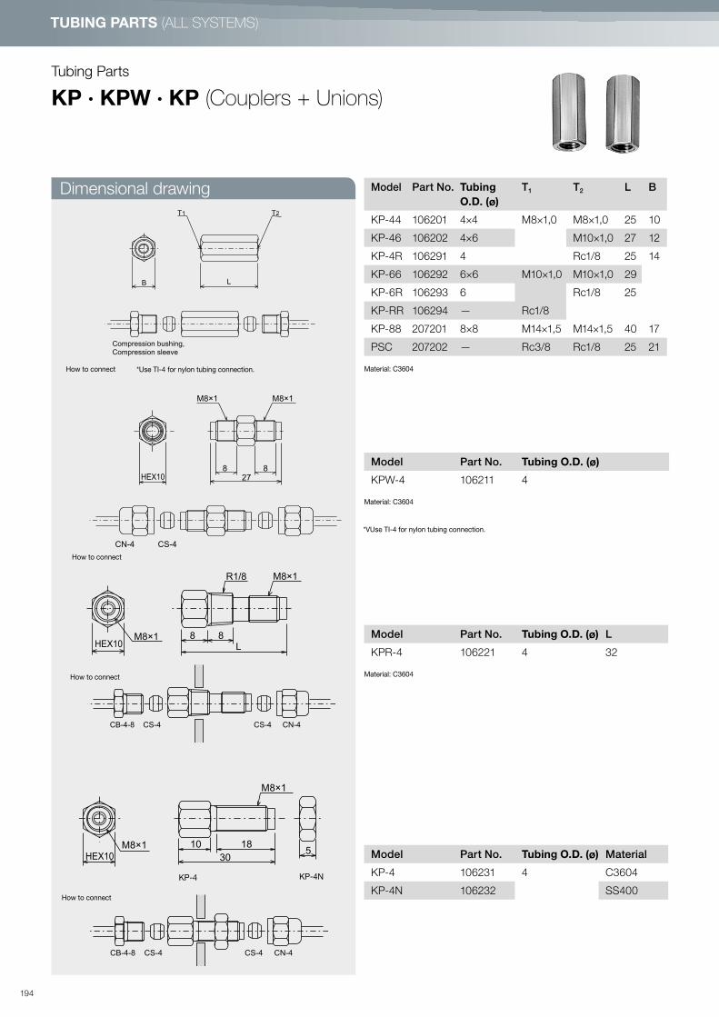
TUBING PARTS (ALL SYSTEMS)
Tubing Parts
KP · KPW · KP (Couplers + Unions)
B
T1 T2
L
Compression bushing,Compression sleeve
27
8 8
M8×1M8×1
HEX10
CS-4CN-4
How to connect
How to connect
*VUse TI-4 for nylon tubing connection.
CB-4-8 CN-4CS-4 CS-4
R1/8 M8×1
8HEX10
8M8×1
L
How to connect
Model Part No. Tubing O.D. (ø)
T1 T2 L B
KP-44 106201 4×4 M8×1,0 M8×1,0 25 10
KP-46 106202 4×6 M10×1,0 27 12
KP-4R 106291 4 Rc1/8 25 14
KP-66 106292 6×6 M10×1,0 M10×1,0 29
KP-6R 106293 6 Rc1/8 25
KP-RR 106294 — Rc1/8
KP-88 207201 8×8 M14×1,5 M14×1,5 40 17
PSC 207202 — Rc3/8 Rc1/8 25 21
Material: C3604*Use TI-4 for nylon tubing connection.
Model Part No. Tubing O.D. (ø) L
KPR-4 106221 4 32
Material: C3604
Model Part No. Tubing O.D. (ø) Material
KP-4 106231 4 C3604
KP-4N 106232 SS400
Model Part No. Tubing O.D. (ø)
KPW-4 106211 4
Material: C3604
How to connect
KP-4 KP-4N
CB-4-8 CN-4CS-4 CS-4
M8×1
10
HEX10
M8×1
30
185
Dimensional drawing
194

TU
BIN
G P
AR
TS
KBC · KBL · OTS · OTE (Push-in fitting)
SpecificationsOperating pressure Oil: Under 3 MPa Grease: Under 4 MPa
Life Oil: Under 1,000,000 times Grease: Under 100,000 times
Working viscosity range 2
Ambient temperature range 0 – 60°C
Vibration resistance 4.5G 10 – 55Hz, 9G 55Hz (Fixed)
Model Part No. Outer
diameter
of tube (ø)
L1 L2 B
OTS-4 106369 4 25 22 10
OTS-6 206152 6 27 24 12
For use with nylon tube only.
Push-in fitting (Straight)
Model Part No. Outer
diameter
of tube (ø)
B
OTE-4 106373 4 10
OTE-6 206155 6 12
For use with nylon tube only.
Push-in fitting (Elbow)
B
(26)
R1/8
(20)
20
8
SpecificationsUsed liquid Lubrication oil
Max. working pressure 6 MPa
Working viscosity range 10 mm2/s
Vibration resistance 9G
Model Part Number
KBE4-01-F 209523
Material: C3604
*Swivel fitting is designed to set direction easily, not to for use at movable places according to the machine movement.
ModelPart
No.
Outerdiameterof tube (ø)
T B L1 L2
KBC4-01-F 209503
4
R1/8 HEX10
21
8
KBC4-02-F 209504 R1/4 HEX14 11
KBC4-M6-F 209501 M6×1.0HEX10
4.5
KBC4-M6P0.75-F 209502 M6×0.75 20 3.5
KBC6-01-F 209513 6 R1/8 HEX12 22.6 8
Material: C3604
Model Part No. Outerdiameterof tube (ø)
T L1 L2 L3 L4
KBL4-01-FN 209508 4 R1/8 26 21 8 17.4
KBL4-M6-FN 209506 M6×1.0 22.5 17.5 4.5
KBL6-01-F 209518 6 R1/8 27.5 21.5 8 20.2
Material: C3604*Swivel fitting is designed to set direction easily, not to for use at movable places according to the machine movement.
B
HEX10
ø7
L1
L1
L2
L4
L2
L3
ULBE
4T
T
R1/8
ø1018
23
7.5
101419
ø4 Tubing
B
HEX10
ø7
L1
L1
L2
L4
L2
L3
ULBE
4T
T
R1/8
ø1018
23
7.5
101419
ø4 Tubing
B
HEX10
ø7
L1
L1
L2
L4
L2
L3
ULBE
4T
T
R1/8
ø1018
23
7.5
101419
ø4 Tubing
Dimensional drawing
195

TUBING PARTS (ALL SYSTEMS)
Dimensional drawing
Dimensional drawing
Tubing Parts
SAG · ECMG (Fittings for limited space)
RoHS compliant products are also available. Please contact LUBE for details.
Model Part No.
NYB 109405
NYS 109406
Model Part No.
ECMG-6BL 166039
Model Part No. Tubing O.D. (ø)
SAG4-6B 1063664
SATG-6B 106064
Material: C3604
Rc 1/8Rc 1/8
2412
67
20 12
33
11
6124 12
17
5
[NYB] [NYS]
How to connect
NYB · NYS (Nylon Brush)
M6×0.75M8×1.0φ
8
8 2
18HEX9
8
M8×1M6×0.75
HEX8 30
14
CS-4: P.203
CN-4: P.203
SAG4-6B
SATG-6B
M6×1
Taper 1/16
T
L1
41
L2□9
ECMG-6AL, ECMG-6ALL
CN-4
: P.203
CS-4
: P.203
SAT-6A
: P.209
10
M6×1M6×0.75
1014
ECMG-6BL
Model Part No. L1 L2 T
ECMG-6ALL 106382 23 14 M6×1
ECMG-6AL 106383 20 11 M6x1
196
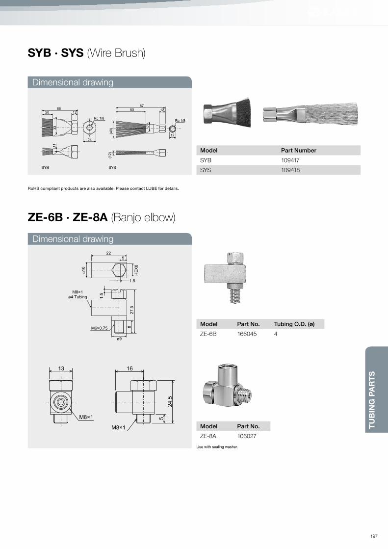
TU
BIN
G P
AR
TS
Dimensional drawing
Dimensional drawing
SYB · SYS (Wire Brush)
RoHS compliant products are also available. Please contact LUBE for details.
Rc 1/8Rc 1/8
24
12
(12)
(40)
6820 12
33
11
8750 12
17
Model Part No. Tubing O.D. (ø)
ZE-6B 166045 4
Model Part No.
ZE-8A 106027
Model Part Number
SYB 109417
SYS 109418SYB SYS
22
5
1.5
1.5
27
.58
ø9
M6×0.75
M8×1
ø4 Tubing
HE
X8
□10
Use with sealing washer.
ZE-6B · ZE-8A (Banjo elbow)
5
24.5
16
M8×1
M8×1
13
197

TUBING PARTS (ALL SYSTEMS)
Dimensional drawing
Tubing Parts
SC (Fittings for steel tubing)
Sleeve
Model Part No. Outer diameter d T L B1 B2
S61-SC 250111ø 6
R1/8 34.5 14.0 14.0
S62-SC 290191 R1/4 37.5 17.0
S81-SC 250131ø 8
R1/8 35.5 17.0
S82-SC 290190 R1/4 37.5
Modell Part No. Outer diameter d L B1 B2
U6-SC 250112 ø 6 43.0 14.0 14.0
U8-SC 250132 ø 8 52.0 17.0 17.0
Model Part No. Outer diameter d L B
EU6-SC 250114 ø 6 26.5 14.0
EU8-SC 250134 ø 8 33.5 17.0
Model Part No. Outer diameter d L1 L2 B
T6-SC 250115 ø 6 53.0 26.5 14.0
T8-SC 250135 ø 8 67.0 33.5 17.0
Model Part No. Outer diameter d L B
N6-SC 250119 ø 6 13.0 14.0
N8-SC 250139 ø 8 15.0 17.0
Model Part No. Outer diameter d L
F6-SC 250118 ø 614
F8-SC 250138 ø 8
Model Part No. Outer diameter d T L1 L2 B
E61-SC 250113ø 6
R1/8 30.5 14.0 14.0
E62-SC 290184 R1/4 33.5 17.0
E81-SC 250133ø 8
R1/8 16.0 17.0
E82-SC 290043 R1/4 18.0
Material: S25C
d
L
Straight nipple
Union
Elbow nipple
Elbow union
Tee
Nut
TB1
d
L
B2
d
L2
L1
B
d
T
L1
L2 B
d
L
L
B
d
L
B2B1
d
L
B
198

TU
BIN
G P
AR
TS
Dimensional drawingStraight nipple
Union
Elbow nipple
Elbow union
Tee
Nut
Sleeve
BD (Fittings for copper tubing)
Material: C3604BD
Model Part No. Outer diameter d T L B1 B2
S61-BD 250101ø 6
R1/8 27.0 12.0 12.0
S62-BD 290219 R1/4 34.0
14.0 17.0S81-BD 250121ø 8
R1/8 31.0
S82-BD 290245 R1/4 35.0
Model Part No. Outer diameter d L B1 B2
U6-BD 250102 ø 6 32.0 12.0 12.0
U8-BD 250122 ø 8 40.0 14.0 17.0
Model Part No. Outer diameter d L B
EU6-BD 250104 ø 6 20.0 14.0
EU8-BD 250124 ø 8 29.0 17.0
Model Part No. Outer diameter d L1 L2 B
T6-BD 250105 ø 6 40.0 20.0 14.0
T8-BD 250125 ø 8 58.0 29.0 17.0
Model Part No. Outer diameter d L B
N6-BD 250109 ø 6 11.0 14.0
N8-BD 250129 ø 8 13.0 17.0
Model Part No. Outer diameter d L
F6-BD 250108 ø 6 6.5
F8-BD 250128 ø 8 8.0
Model Part No. Outer diameter d T L1 L2 B
E61-BD 250103 ø 6 R1/8 20.0 17.0 12.0
E62-BD 290277 R1/4 25.0 22.0 17.0
E81-BD 250123 ø 8 R1/8 26.0 19.0
E82-BD 290246 R1/4 22.0
TB1
d
L
B2
d
L2
L1
B
d
T
L1
L2 B
d
L
L
B
d
L
B2B1
d
L
B
d
L
199

TUBING PARTS (FOR OIL-SYSTEM)
Dimensional drawing
Dimensional drawing
Dimensional drawing
Model Part Number d (ø)
J02 225008 0.2
J05 225007 0.5
J08 225006 0.8
ModelPart
No.
Tubing
(ø)L2 L2 T1 T2 B d (ø)
NA-05 106974 4 16 8 M8×1 R1/8 10 0.5
NA-08 106975 0.8
Model Part Number Specifications
SVL 109412 0.8 MPa 100 rpm/MAX
□13
31
12 HEX14
R1/8Rc1/8
M8×1
M10×1ø4 Tubing
14
33
d
B
T1
T2
d
L2
L1
Tubing Parts
SVL (Swivel elbow)
J02 · J05 · J08 (Jet nozzle)
NA-05 · NA-08 (Nozzle adapter)
200
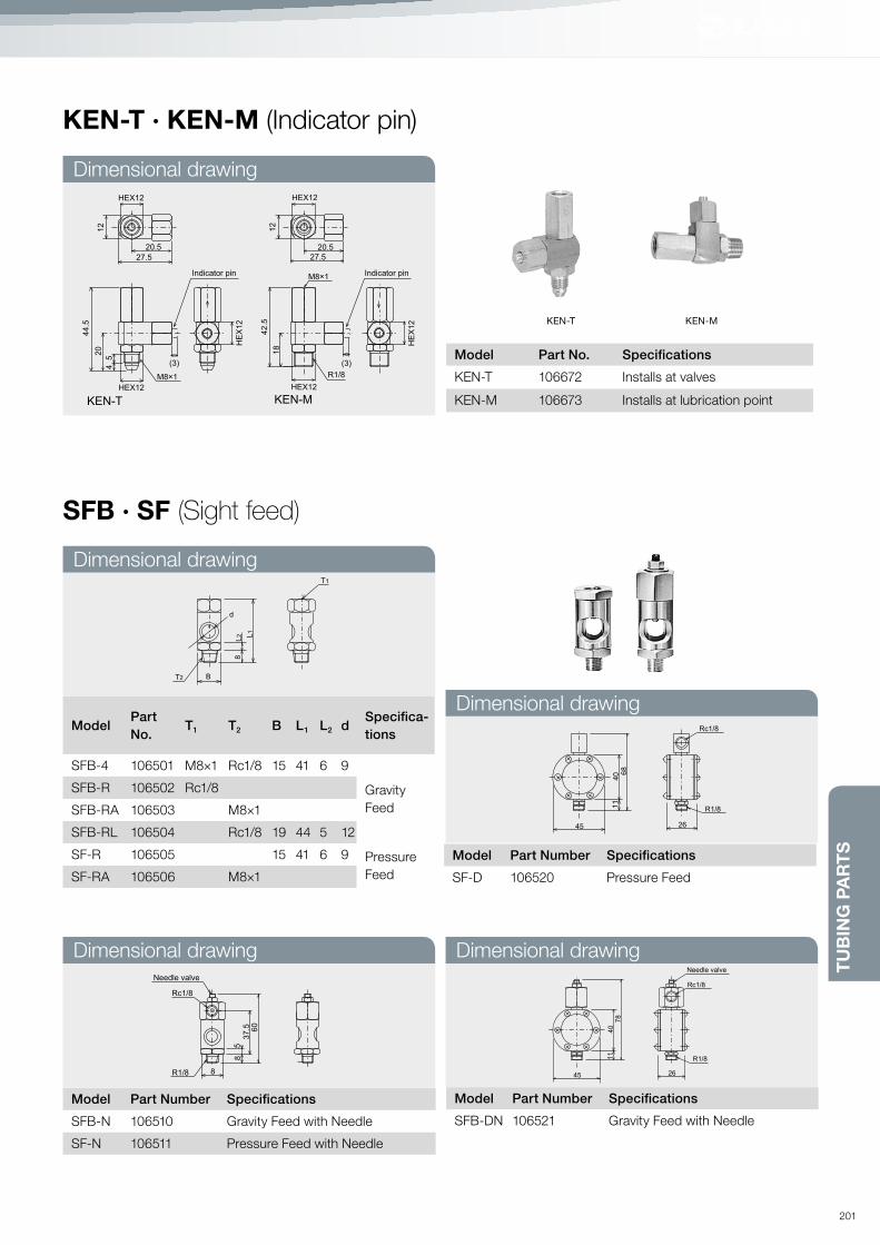
TU
BIN
G P
AR
TS
Dimensional drawing
Dimensional drawing
Dimensional drawing Dimensional drawing
Dimensional drawing
KEN-T · KEN-M (Indicator pin)
KEN-T KEN-M
SFB · SF (Sight feed)
ModelPart
No.T1 T2 B L1 L2 d
Specifica-
tions
SFB-4 106501 M8×1 Rc1/8 15 41 6 9
Gravity
Feed
SFB-R 106502 Rc1/8
SFB-RA 106503 M8×1
SFB-RL 106504 Rc1/8 19 44 5 12
SF-R 106505 15 41 6 9 Pressure
FeedSF-RA 106506 M8×1
Model Part Number Specifications
SFB-N 106510 Gravity Feed with Needle
SF-N 106511 Pressure Feed with Needle
Model Part Number Specifications
SF-D 106520 Pressure Feed
Model Part Number Specifications
SFB-DN 106521 Gravity Feed with Needle
Model Part No. Specifications
KEN-T 106672 Installs at valves
KEN-M 106673 Installs at lubrication point
12
42.5
18
HEX12
HEX12
HE
X12
20.5
27.5
(3)
R1/8
M8×1
12
44.5
20
45
HEX12
HEX12
HE
X12
20.5
27.5
(3)
M8×1
Indicator pin Indicator pin
KEN-T KEN-M
T1
T2
8
B
d
L1
L2
60
37
.5
85
Rc1/8
R1/8
Needle valve
8
68
11
40
45 26
Rc1/8
R1/8
11
40
45 26
Rc1/8
Needle valve
R1/8
78
201

TUBING PARTS (FOR OIL-SYSTEM)
Dimensional drawing
Model Part No. Specification T B
STE-4A 106931
Threaded
type
M4 × 0.7 6
STE-5A 106933 M5 × 0.8
STE-6B 106935 M6 × 0.75 8
STE-6A 106936 M6 × 1
STE-8B 106937 M8 × 1.25 9
HSAC
HJBC
HTUC
Model Part Number Operation Pressure (MPa)
HSAC 109407 0.034
HJBC 109415 0.034
HTUC 109416 0.016
Model Part No. Specification T L B
ETE-4A 106911
Threaded
type
M4 × 0.7 13.5 6
ETE-5A 106913 M5 × 0.8 15 8
ETE-6B 106915 M6 × 0.75
ETE-6A 106916 M6 × 1
ETE-8B 106917 M8 × 1.25 16 9
Tubing Parts
STE · ETE (Drive bushing / Barb fitting)
HSAC · HJBC · HTUC (Check valves)
6 7
φ3
T
B
16
T
7ø3
B
L
17
Nylon tubing
R1/8
25HEX10
M8×1
29.5
M8×1 M8×1
HEX10
R1/8 R1/8
23HEX10
Dimensional drawing
202

TU
BIN
G P
AR
TS
Model Part No. Applicable pump
Oil fill cap
OC-1 549006 L3, L8
OC-2 549005 EX, L20, ACM-II, AM, ADM
OC-3 529432 mlZ, L5
OC-4 529409 AMZ-III, AMZ100S, AMO-150S-III, AMO-II-150S, MMXL-III, MMX-II, AMR-III-150
Strainer OS-1 521037 AMZ-III, AMZ100S, AMO-150S-III, AMO-II-150S, MMXL-III, MMX-II
Suction filter
SF-01 489001 AM, ADM
SF-05 489005 L20, EX
SF-07 489007 mlZ
SF-08 489008 AMI-300S, AMI-1000S, AMI-300, AMI-1000
SF-10 489010 MMXL-III
SF-11 489011 AMZ-III, AMZ100S, AMO-150S-III, AMO-II-150S, AMR-III-150
SF-12 489012 ACM-II
SF-13 489013 MMX-II, L8
SF-A 500324 AMS
SF-L3 540727 L3
SF-L5 540562 L5 . LK
Inlet check
valve
IC-2.5 529008 MMX-II (2.5 mℓ)
IC-5.5 529009 MMX-II (5.5 mℓ), L-8, L-20
IC-EX 539001 mlZ, LK
Outlet check
valve
OC-1 509001 MMX-II, EX, L-8, L-20
OC-2 549070 mlZ, LK
Relief valve
RV-0,5 519003 AMI-300 <0.5 MPa>
RV-0,8 509002 AM, ACM, ADM, AMS <0.8 MPa>
RV-2.5 519002 AMI-100S, 200S, 300S, 1000S <2.5 MPa>
Oil pump replacement parts
203

SERVICE
204

Seminar Information P. 212
LRA Analysis (Real Oil Film Analysis) P. 207
System PlanningCentralized lubrication system planning P. 208
LHL + Grease-System Planning P. 210
Reference for lubricant (Classified by JIS standard) P. 214
Oil-System Planning P. <?>
InstallationTubing connection method P. 226
Tightening torque table P. 228
TroubleshootingLHL + Grease-System P. <?>
Oil-System P. 231
205

SERVICE
Seminar information on basic lubrication systems
Understanding preventive maintenance techniques
Contents of the seminar
A sound introduction to lubrication techniques at worksites secures reliability and maintainability of machinery and equip-
ment. This yields significant economic effects, including not only effective operation of equipment but also quality assurance
of finished products. Through this seminar on preventive technology using lubrication, we would like to help you improve your
lubrication and preventative maintenance techniques.
1 Importance of machine lubrication and maintenance 10 min.
1. Types of lubrication trouble in machinery and equipment
2. Importance of lubrication control in regards to failure rates
3. Difference between manual oiling and automatic lubrication
4. Difference between oil and grease
5. Why should designated lubricants be used?
2 Outline of LUBE’s centralized grease systems 20 min.
1. Centralized grease systems
· Types of centralized grease systems
· Outline of LUBE’s positive displacement injector system
· Outline of LUBE’s series progressive system
2. Principles of operation
3. Comparison of centralized grease systems
4. How to select systems and cautions
3 Maintenance of centralized lubrication systems 30 min.
1. Safe use of systems
2. Precautions for maintenance
3. Why LUBE special greases are approved for use by many machine manufacturers
Questions and answers 20 min.
206

SE
RV
ICE
LUBE offers LRA to find the best suited lubrication film state for your machines. Based on this analysis, we propose the mini-
mal quantity lubrication (MQL) program specifically for your manufacturing environment.
(1) Reduces runnning costs
(2) Maintains accuracy and performance of your machines and their essential parts
(3) Reduces CO2 Emissions
Diagnostics
LRA (LUBE Real oil film Analysis)
LRA
History
Quantities of particles
Remarks
Representative particles
are shown.
In the remarks column,
a description is given of
the location of wear,
cause of occurrence,
whether or not overhaul
is required, etc.
Analysis No.
Our control No. is assigned
from sample to sample.
Date of sampling
Customer sampling date
At the oil inlet point (large
wear particle concentration),
and 5 mm downstream of the
inlet point (small wear particle
concentration) on the particle
concentration ferrogram of
the oil trapped on the
ferrogram.
Configuration of particles
Types, forms, and quantities
of wear particles trapped on
the ferrogram are described.
Outline of particles
Example report of LRA Analysis
207

SERVICE
Objective of lubrication: Decrease friction, cooling and extend
bearing life.
• Locate all wear surfaces that need to be lubricated:
bearings, slides, cams, gears, chains etc. Take into
consideration RPM, load, ambient temperature and nearby
hazards.
• Selecting lubricant: Determine frequency required (min.
-hrs. -days). Select lubricant oil or grease, and note viscosity
• Selecting Desired Delivery Method: Automatic or manual,
Intermittent or continuous, Single Line Resistance, Positive
Displacement Injector or Series Progressive.
• Calculate Lubricant Requirements: For each lubrication
point, calculate the necessary lubricant volume in cubic
centimeters per hour. Then multiply or divide by desired
frequency to determine necessary requirement per interval
cycle. Add all the requirements together to get the total system
requirement.
• Select Distributor: Based on the desired delivery method,
choose the correct distributor for that method that will deliver
the amount of lubricant required per interval period.
• Select Pump and Reservoirs: Based on the desired delivery
method and the system total requirements, choose a pump
that meets those requirements. Take into consideration it is
not recommended to use more than 80% of the pump output.
Choose a reservoir that will meet the desired refilling interval.
• Select any Protection and Monitoring Device: Based on the
type of system there are different monitoring devices that could
be used if desired (flow sensor, pressure switch, cycle switch,
low level switch or visual indication).
• Select Controlling Method: Determine if an external system
controller will be required and select controls that will not only
meet the system requirements, but also the chosen monitoring
device if necessary.
• System Layout: Arrange nearby lubrication points into groups if
desired. Based on the particular distributor chosen, arrange the
distributors into same groups. Based on the system delivery
method and necessary main and branch tubing, engineer the
tubing layout and distributor locations.
• Select Necessary Tubing Parts: After system layout is com
plete, choose the correct amount of desired fittings, adapters,
compression hardware, tubing etc. that will be required to
plumb the system.
(1) System planning sequence (2) Calculating oil requirements
The amount of oil that is required for lubrication point is calculat-
ed by the following formulas and are based on experience and
actual testing.
The necessary requirement is calculated in cubic centimeters
per hour. These formulas are based on an average of 120 RPM.
In general, the requirement should be doubled for every ten fold
speed increase. There have been many calculating formulas
published before that use surface smoothness, different op-
erating conditions, RPM, load, ambient temperature, oil type,
hazardous conditions, sealing conditions etc. Thus, the formulas
below for calculating the oil requirements are not absolute.
They are rather a benchmark, and should be adjusted based on
actual operating conditions.
Oil requirements calculation formulas
The relationship between rpm and multiplier
AF. BW.
CA.
G.
CH.
P.
FW.
CW.
Anti-friction bearing
(Ball bearing, roller bearing,
needle bearing)
Oil volume Q (cc/h)
= 0.04 × diameter × rows
Plain bearing
Oil volume Q (cc/h) = 0.023 × shaft
diameter × bearing length
Flat slide
a. Oil volume
Q (cc/h) = 0.0017 × length × width
(horizontal slide)
b. Oil volume
Q (cc/h)=0.006×length×width(vertical slide)
Cylinder slide
Oil volume
Q (cc/h) = 0.023 × diameter × length
Ball bearing way
Oil volume
Q (cc/h)= 0.012×length×rows
Cam
Oil volume Q (cc/h)= 0.0017×
Contacting circumference
× width
Gear
Oil volume
Q (cc/h) = 0.013×pitch circle
diameter × width of gear
Chain
Oil volume
Q (cc/h)=0.008×length×width
0.2
20 30 50 100 200 300 500 1000 2000 5000 10000 20000
0.4
0.6
0.8
1
1.2
1.4
1.6
1.8
2
2.2
2.4
2.6
2.8
3
MU
LT
IPL
IER
U / Min.
System Planning
Centralized lubrication system planning
208

➔ LHL + GREASE- SYSTEM PLANNING
209

SERVICE
System Planning
Grease-System (PDI)
The Grease centralized lubrication systems will deliver precise
amounts of grease to all of your lubrication points, and have
the flexibility to be adapted to just about any application
imaginable. The Grease systems have a wide assortment
of manual, pneumatic and electric pumps to satisfy any
lubrication requirement. The integrity of these systems stems
from its metering device the MG2 (C)-Valve injector. There is
also the option of an MGI-Valve which incorporates the use
of a visual indicator pin at the valve which will pop out in
the event of a clogged tail tube. MG2 (C) Valve injectors are
precisely calibrated piston distributors that will deliver an
exact amount of grease upon main line pressure rise from
the pump you choose. The MG2 (C) and MGI-Valve injectors
will re-set and re-load when main line pressure returns to
zero. These systems have been designed and proven to work
effectively with grease ranging from NLGI-000 to NLGI-1.
Lubrication System Positive displacement injector system
Tubing Single line (main tubing ø 8 mm, tail tubing ø 4 mm)
Pump Manual Motor driven
Model EGH-4C EGM-10S-4-7C
Discharge volume 1 cc/stroke 10 cc/min
Discharge pressure 10 MPa (100 kgf/cm2) 10 MPa (100 kgf/cm2)
Reservoir 0.4 ℓ 0.4, 0.7 ℓ
Controller — —
Distributor
MG2 valve
Model Positive Displacement Injector (PDI)
Operating pressure 2.5 MPa (25 kgf/cm2)
Operating pressure 1.4 MPa (14 kgf/cm2)
Discharge volume 0.03, 0.05, 0.1, 0.2, 0.3, 0.5, 1.0, 1.5 cc stroke
Working lubricant NLGI No. 000, 00, 0, 1
Working environment temperature +10°C/+50°F for NLGI No. 1 and above 0°C/+32°F for NLGI No. 000, 00 and 0
General view of specifications of major types of pump
(1) System Overview
<System layout example>
Manual Pump
Automatic Pump
Junction
Main tubing
MG2-Valve
Tail tubing
Point of lubrication
210

SE
RV
ICE
Characteristics:
1. There are numerous manual, pneumatic and electric pump
with ranging output delivery per cycle and per minute, to
satisfy not only your chosen deliverymethod, but more impor
tantly to satisfy your bearing requirements.
2. MG2 (C)-Valve injectors have 8 different discharge volumes to
select from to meet the lubrication points actual cycle require
ment.
3. MGI-Valve injectors have 6 different discharge volumes to
select from to meet the lubrication points actual cycle require
ment, as well as having a visual indication pin for clogged tail
tubes.
4. Both MG2 (C) and MGI-Valves are junction mounted distribu-
tors that can be arranged in just about any configuration im-
aginable.
5. Because the Grease Systems have the flexibility of individual
distributor junction assemblies using one main line tube,
makes the engineering of the system layout and installation of
the system as easy as possible.
Initial Grease Volume Required
There is a tendency that people oversupply grease due
to a concern that grease supply may not be enough :
Excessive grease will increase power consumption and heat
produced by excessive load of the grease and it may also
cause grease leakage. So everything should be taken into
consideration when deciding the grease volume. There is a
large gap between the least amount grease given to bearing
without damaging the bearing and the largest amount of
grease given to the bearing without grease leaking out of
the bearing. But what is the best grease volume? This ideal
grease volume can be described in several ways. In general,
(1) 1/2 - 3/4 of the space between the bearing and its housing.
(2) 2/3 - 3/4 of the space between the bearing and bearing
cover, when the bearing is installed horizontally;
(3) 1/2 of the space between the bearing and its top cover
and 3/4 of the space between the bearing and its bottom
cover, when the bearing is installed vertically;
(4) Fill grease in the bearing and bearing cover for the low and
medium speed bearing if in dusty atmosphere;
(5) When replacing the grease in bearing, the grease volume
should be calculated by the following formular
Q = D2.5/K……(1)
D: Bearing diameter (mm)
K: Constant Ball bearing K=900
Roller bearing K=350
These formulas are just basics. Actual grease volume need to
be adjusted by rpm, load, and the bearing housing size in actual
use.
Variables to be considered
1. Total tubing length… m
Total tubing length is the combined length of steel tubing
(copper tubing) and flexible hose of the main tubing.
(2) System planning sequence
2. Total grease output metering valve …cc
Total grease output of metering valve is the total discharge
volume of the valves.
3. Pressure relief time:
The time required for the pressure relief mechanism to relieve
the pressure at the end of the main tubing down to valve reset
pressure (1.4 MPa (14 kgf/cm2) after all valves have dis-
charged. It is determined by the total length of tubing and the
grade of the grease.
4. Interval time:
The time between one discharge and the next discharge. The
interval time should be longer than the time required for pres-
sure relief and valve reset time combined.
5. Pump pressure rise time
The time required for the pump to raise the pressure at the
end of the main tubing up to 5 MPa (50 kgf/cm2 ).
6. Operating environment temperature
The operating environment temperature for NLGI No. 1 is over
+10 °C/ +50 °F and above 0 °C/ +32 °F for 000, 00 and 0
grade grease.
7. Grease specifications
Use lithium based grease with NLGI No. 000 - 1 grade.
211

SERVICE
System Planning
Grease-System (EGH-4C Pump)
1. Select the valves based on the grease volume required to each lubrication point.
2. The total valve grease discharge volume is restricted by the number of handle operation. Also the total length of main line tubing
needs to be considered along with the viscosity of the grease for pressure relief time required.
Grease
Total length
of tubing
No. 000 No. 00 No. 0 No. 1
0°C/
+32°F
+10°C/
+50°F
+20°C/
+68°F
0°C/
+32°F
+10°C/
+50°F
+20°C/
+68°F
0°C/
+32°F
+10°C/
+50°F
+20°C/
+68°F
+10°C/
+50°F
+20°C/
+68°F
2 m/6.5 F 25″ 15″ 2″ 1′00″ 45″ 25″ 11′00″ 6′00″ 1′00″ 11′00″ 6′00″
4 m/13.1 F 45″ 25″ 2″ 2′00″ 1′20″ 45″ 22′00″ 12′00″ 2′00″ 22′00″ 12′00″
6 m/19.7 F 1′00″ 30″ 2″ 3′00″ 2′15″ 1′00″ 36′30″ 20′00″ 3′00″ 36′30″ 20′00″
8 m/26.2 F 1′30″ 45″ 2″ 5′30″ 3′30″ 1′30″ 50′30″ 28′00″ 5′30″ 50′30″ 28′00″
10 m/32.8 F 2′00″ 1′00″ 2″ 8′00″ 5′00″ 2′00″ 1°04′00″ 36′00″ 8′00″ 1°04′00″ 36′00″
Temperature
Selection of valve
Interval lubrication time
Pressure Relief time (Table 13)
Interval time should be longer than the time required for presure relief and valve reset time (3 sec) combined.
212

SE
RV
ICE
Grease
Total length
of tubing
No. 000 No. 00 No. 0 No. 1
1 m/3.28 F 3″ 7.5′ 15′ 30′
2 m/6.56 F 6″ 15′ 30′ 60′
4 m/13.1 F 12″ 30′ 60′ 120′
6 m/19.6 F 18″ 45′ 90′ 180′
8 m/26.2 F 24″ 60′ 120′ 240′
10 m/32.8 F 30″ 75′ 150′ 300′
1. Select the valves based on the grease volume required to each lubrication point.
2. The total length of main line tubing needs to be considered to determine the running time required to build pressure
to cycle the MG2 valves.
2. Valve operating time (T″) Calculate the valve operating time from the valve total output.
V: Valve total output (cc).
Q: Pump discharge volume when valve in operation (15cc / Minute)
The time between one discharge and the next discharge. The interval time should be longer than the time required for pressure
relief and valve reset time (3 sec.) combined.
Pressure relief time (Table 20)
1. Steel tubing
2. When using flexible hose
The pressure relief time for the steel tubing, plus it for the flexible hose.
Total length of tubing Pressure rising time
10 m (32.8 feet) 15 sec
Grease
Total length
of tubing
No. 000 No. 00 No. 0 No. 1
10 m/i.oF 15″ 15″ 30″ 60″
Pump operating time (T)
Calculate the operation time (T) by adding the pressure rising time (T′) and valve action time (T″). T=T′+T″1. Pressure rising time
Steel tubing (ø 8) (Table 19)
V×72T”=
Q’
5 V
Selection of valve
System Planning
Grease-System (EGME II-8S Pump)
213

SERVICE
Type
Temperature
range of
application
Reference
Propriety to
working conditionExample of application
Application Type Grade number Load
Contact
with
water
Low HighIm-
pact
General grease
1No. 1, No. 2,
No. 3, No. 4
-10 °C/ + 14 °F –
+60 °C/ + 140 °FYes No No Yes For general low load
2 No. 2, No. 3-10 °C/ + 14 °F –
+100 °C/ + 212 °FYes No No No For intermediate load
Roller bearing
grease
1 No. 1, No. 2, No. 3-20 °C/ − 4 °F –
+100 °C/ + 212 °FYes No No Yes General
2 No. 0, No. 1, No. 2-40 °C/ − 40 °F –
+80 °C/ + 176 °FYes No No Yes For low temperature
3 No. 1, No. 2, No. 3-30 °C/ − 22 °F –
+130 °C/ + 266 °FYes No No Yes
For wide range
of temperature
Centralized
lubricating
grease
1 No. 00, No. 0, No. 1-10 °C/ + 14 °F –
+60 °C/ + 140 °FYes No No Yes
For centralized lubrication
(Medium load)
2 No. 0, No. 1, No. 2-10 °C/ + 14 °F –
+100 °C/ + 212 °FYes No No Yes
For centralized lubrication
(Medium load)
3 No. 0, No. 1, No. 2-10 °C/ +14 °F –
+60 °C/ + 140 °FYes Yes Yes Yes
For centralized lubrication
(High load)
4 No. 0, No. 1, No. 2-10 °C/ + 14 °F –
+100 °C/ + 212 °FYes Yes Yes Yes
For centralized lubrication
(High load)
High load grease 1No. 0, No. 1,
No. 2, No. 3
-10 °C/ + 14 °F –
+100 °C/ + 212 °FYes Yes Yes Yes For high impact load
Gear compound 1 No. 1, No. 2, No. 3-10 °C/ + 14 °F –
+100 °C/ + 212 °FYes Yes Yes Yes Open gear and wire rope
ISO
viscosity
grade
Dynamic
viscosity
range
Central
value
ISO
viscosity
grade
Dynamic
viscosity
range
Central
value
cSt (mm/sec)
+40 °C/ + 104 °F
cSt (mm/sec)
+40 °C/ + 104 °F
ISO-
VG15001350 – 1650 1500 ISO VG46 41.4 – 50.6 46
VG1000 900 – 1100 1000 VG32 28.8 – 35.2 32
VG 680 612 – 748 680 VG22 19.8 – 24.2 22
VG 460 414 – 506 460 VG15 13.5 – 16.5 15
VG 320 288 – 352 320 VG10 9.0 – 11.0 10
VG 220 198 – 242 220 VG 7 6.12 – 7.48 7
VG 150 135 – 165 150 VG 5 4.14 – 5.06 5
VG 100 90 – 110 100 VG 3 2.88 – 3.52 3
VG 68 61.2 – 74.8 68 VG 2 1.98 – 2.42 2
Grade
number
(NLGI NO)
Worked
penetrationAppearance
000 445 – 475 Fluid state
00 400 – 430 Semifluid state
0 355 – 385 Semifluid state
1 310 – 340 Soft
2 265 – 295 Soft
3 220 – 250 Semi hard
4 175 – 205 Semi hard
5 130 – 160 Hard
6 85 – 115 Solid
Reference for lubricant
Grease types (classified by JIS standard)
214
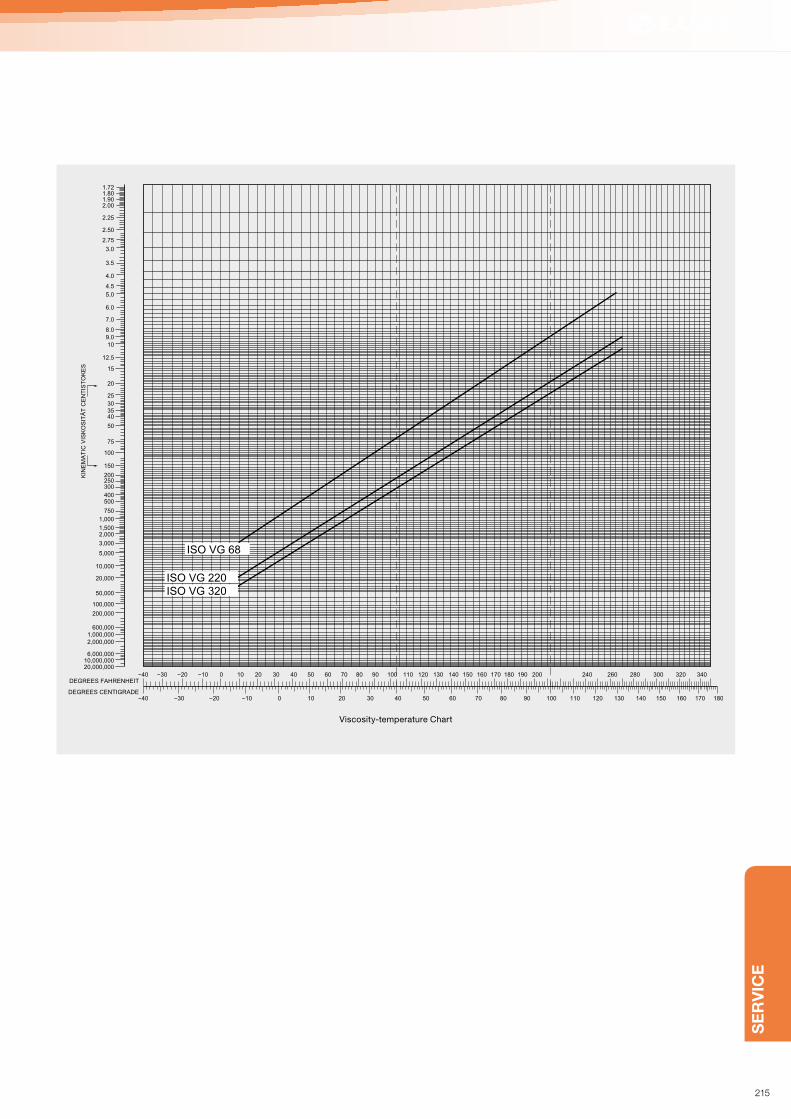
SE
RV
ICE
Viscosity-temperature Chart
ISO VG 220ISO VG 320
ISO VG 68
1.721.801.902.00
2.25
2.50
2.75
3.0
3.5
4.0
4.5
5.0
6.0
7.0
8.09.010
12.5
15
20
25
303540
50
75
100
150
200250300
400500
750
1,000
1,5002,000
3,000
5,000
10,000
20,000
50,000
100,000
200,000
600,0001,000,0002,000,000
6,000,00010,000,00020,000,000
DEGREES FAHRENHEIT
DEGREES CENTIGRADE
KIN
EM
AT
IC V
ISK
OS
ITÄ
T C
EN
TIS
TO
KE
S
−40
−40 −30 −20 −10 0 10 20 30 40 50 60 70 80 90 100 110 120 130 140 150 160 170 180
−30 −20 −10 0 10 20 30 40 50 60 70 80 90 100 110 120 130 140 150 160 170 180 190 200 240 260 280 300 320 340
215

SERVICE
➔ OIL-SYSTEM PLANNING
216

SE
RV
ICE
The AMO-series centralized lubrication system will deliver
precise quantities of oil to all of your lubrication points, and
have the flexibility to be adapted to just about any applications
imaginable.
The AMO-series pumps are electrically operated gear pumps,
and offer many choices for controller options. The integrity of
these system stems from the metering device the MO2 (C)-Valve
injector. The MO2 (C)-Valve injector is a precisely calibrated
piston distributor that will deliver an exact amount of oil upon
main line pressure rise from the AMO-series pump.
The MO2 (C)-Valve re-set and re-load when main line pressure
returns to zero. The AMO-series pumps come standard with
an internal pressure relief valve and a low lubricant switch.
Normally they also have an internal pressure switch that will
monitor the main line for breakage.
AMO-series pumps also have an option for a precision gear
assembly that will allow the use of lubricants light as 22 Cst.
1. The AMO-series pumps can be used with or without
controller whitch allows the flexibility of just about any
time or count interval required.
2. The AMO-series pumps are motor driven gear pumps that
are preset to deliver 150 to 180 cc/min. and create 285 psi of
main line pressure.
3. The AMO-series pumps have a 180 micron suction filter,
but LUBE recommends an additional in line filter for added
security against contamination.
4. The MO2-Valve injectors are junction mounted distributors
that can be arranged in just about any configurations imagi-
nable.
5. The MO2-Valves have 6 different discharge volumes to select
from to meet the lubrication points actual cycle requirement.
6. AMO-series systems have great flexibility of design due to
individual distributor junction assemblies One main line tube
and an optional pressure switch makes the engineering of
the system layout and the installation of the system as easy
as possible, as well as monitoring much of the system for
main line breakage.
Lubrication system PDI System
Tubing Single line (main tubing 6mm, tail tubing 4 mm)
Lubricant Oil (68 – 1800 cSt)
PumpType Motor driven gear pump AMO-II-150S
Discharge volume 150/180cc/min (50/60Hz)
Reservoir 1.8 ℓ, 3 ℓ: Resin / 3 ℓ, 4 ℓ, 8 ℓ: Metal
Controller Built-in (discharge time/interval timer), with indication lamps
Valve MO valve
(1) System Overview Characteristics:
Compression bushing
CB-6: P.188
CP-6: P.189
Compression sleeve
CS-6: P.188
<System layout>
Tubing ø6
Filter
MO2 Metering
valve
Branch tubing ø4
Closure plug
Junction
AMO
Electric gear pump
with 3 ℓ resin reservoir
Oil-System (PDI / AMO)
217

SERVICE
(2) System planning sequence
To be considered
1. Total length of main tubing (L) …m
The total length of the steel tubing and flexible hose in
the main tubing.
2. The distance to the furthest valve (l) …m
The length of the main tubing to the furthest valve from
the pump.
3. Total output of all valves (V) …cc
The total oil output of all valves.
4. Maximum operating viscosity (v)…cSt
The oil viscosity at the lowest temperature of the working
environment. (Not to exceed 1800 cst.)
Designing the system (How to complete Data Sheet)
1. Fill in the column 18 - 21.
2. Calculate required Oil Volume using the formula provided.
Put the results in column 22.
3. Choose the smallest oil requirement from column 22,
using it as the divisor, calculate the relative ratios to all
other oil requirements. Put the results in column 23.
4. Select valves with the least amount of output as possible
and assign the valve to each point. Valve output should be
in accordance with the ratios in column 23. Put the results
in column 24. Calculate the total and put the result in
section 7.
5. Using the valve output in column 24 as the divider, divide
the oil requirements in column 22 and put the results in
column 25.
6. Select the largest value from column 25, using the following
formula, calculate the inteval time for 1 cycle. Put the result
in column 26.
T = 1 interval time of cycle (min)
V = Discharge volume of valve (cc/shot)
Q = Oil requirement (cc/h)
7. Pick the largest value in column 25 and multiply by the
values in column 24 to get the actual oil output per hour.
Put the results in column 27.
8. Select System Specifications
Put the customer information in column 1 – 8 in the System
Specification Section.
9. Select Lubrication Pump
Fill in specifications of the Lubrication Pump in section 17.
10. Based on the working viscosity in section 2 and the main
line tubing length in section 6, use the table 1 to figure out
pump discharge volume and put the result in section 9.
11. Use the following formula to calculate the valve operation
time based on the data of total discharge volume of valve in
section 7 and Pump Discharge Volume When the Valve in
Operation in section 9 and put the result in section 10.
T’ = Operating time of valve (sec)
V = Total discharge volume of valve (cc)
Q’ = Pump discharge volume when the valve
in operation (cc/min)
12. Use table 2 to establish the time to reach the maximum
pressure.
13. Use the Valve Operation Time in section 10 and the Pressure
Rise Time in section 11 to get the Minimum Discharge Time
of the pump and put the result in section 12.
14. Establish the pressure relief time by using the table 3 and
put the result in section 13.
15. Set the Valve Reset time as 1.5 second according to the
valve specification.
16. Calculate the pump minimum interval time from the Pressure
Relief Time in section 13 and the Valve Reset Time in
section 14. Put the result in section 15.
17. Calculate the Minimum Lubrication Cycle from the Pump
Minimum Discharge Time in section 12 and the Minimum
Interval Time in section 15. Put the result in section 16.
18. If the Minimum Lubrication Cycle in section 16 is longer than
the lubrication cycle, the system would lose its integrity.
Then the number of lubrication points should be reduced or
adjust the Total Oil Discharge Volume of Valves in section 7.
T=
v×78
Q’
T=
v×60
Q
System Planning
Oil-System (PDI / AMO)
218

SE
RV
ICE
System specifications
cc cc/h
AMO- III DS
: 1.8l, 3ℓ
: 4l, 6ℓ, 8ℓ
Yes/No
φ VAC Hz
μF
1.5
l
ml/min
sec
sec
sec
sec
sec
sec
sec
sec
sec
sec
sec
cSt
m
m
m
m
ml
ml
ν
L
L′
V
V′
L″
Item
Item
1
18 19 20 21 22 23 24 25 26 27
9
10
14
15
16
17
11
12
13
2
3
4
5
6
7
8
Name of CompanyAdd.Section in chargePerson in charge
Name of sales officeDateQuote No.
Machine namesMachine model
LUBRICATION SYSTEM DATA SHEET
(AMO- DS-SYSTEM)
A F
P
F W
C W
B W
G
C A
C H
0.04
0.023
0.023
0.00170.006
0.012
0.046
0.013
Antifriction (ball,roller,needle) bearing
Plain bearing (metal)
Flat side way
Cylinder slide way
Ball roller bearing slide way
Gear
Cam
0.008Chain
Working oil
Maximale Konsistenzklassen
Total length of tubing
Total length of steel(copper) tubing
Total length of flexible hose
Distance to the furthest
Total oil discharge volume of valves
Maximum discharge volume of valve
System planning
Pumpe discharge volume when valve operating
Ventil operating time
Pressure risetime
Steel(copper) tubing
Flexible Hose
System
Minimum discharge time of pump
Pressure relief time
Steel (copper) tubing
Flexible hose
System
Reset time of valve
Minimum interval time of pump
Minimum lubrication cycle time
Lubricating pump
Motor
Condenser
Reservoir
ControllerCalculation of required oil volume
Lubrication points
Name of lubricating parts
Total Total
Abbreviated name Coefficient Dimension Width Calculating value
Bearing diameter
Diameter
Width
Diameter
Slide direction length
Pitchdiameter
Contacting circumference
Length
Row number
Row number
Length
Gear
Width
Width
Length
Length
RP
M o
r strok
e (strok
e/min
)
Oil req
uirem
ent(m
l/h)
Ratio
Ventil discharge volum
e (cc/Hub)
Nu
mb
er of d
ischarg
e
Lu
bricatin
g cy
cle time(m
in)
Actu
al oil v
olu
me
Data sheet
219

SERVICE
Pump
Total length
(m)
AMO-III DS-150S
Steel tubing Flexible hose
2 3.5 6
5 4.5 7.5
10 6 10.5
15 7.5 13.5
20 9 16.5
25 10.5
30 12
35 13.5
40 15
45 16.5
50 18
Each pump common
Total length (m) Steel tubing Flexible hose
2 5.5 5.5
5 5.5 6
10 6 7
15 6.5 7.5
20 7 8.5
25 7.5 9
30 8 10
35 8.5
40 9
45 9.5
50 10
Main tubing
Pressure rise time (Table 2) (0 - relief pressure…sec)
Pressure rise time (Table 3) (0 - relief pressure…sec)
150
mℓ/min
5m
1m
10m
20m
30m
40m
50m
100
50
65 100 500 1000 2000cSt10
0
170
Dis
charg
e v
olu
me o
f pum
p Q
Dis
tance to the tubin
g e
nd
Maximum working viscosity
Pump discharge volume when valve in operation (Table 1)
System Planning
Oil-System (PDI / AMO)
220

SE
RV
ICE
The basic principle of centralized lubrication systems is that oil will travel to the path of least resistance. These systems can
be engineered to be either intermittent or continuous depending on the particular requirements. For intermittent systems the
metering restrictors are called Flow Units and have 8 restriction sizes to choose from. For continuous systems the metering
restrictors are called Control Units and have 10 restriction sizes to choose from. In either case for every size increase or
decrease the amount of restriction will be either half or doubled from the previous size. Flow and Control units will deliver oil
in a low pressure and small volume either intermittently or continuously depending on the chosen system, and have a wide
range of working viscosities. LUBE SLR Systems can be used from small high precision machine to large casting machinery.
Characteristics:
1. Because it is a single main line system, the layout engineering and installation are simple, and visual inspection is easy.
2. There are numerous LUBE SLR electric piston pumps with various outputs, sizes and voltages to fit and lubricate just
about any automatic intermittent application.
3. There are numerous LUBE SLR electric gear pumps with various outputs, sizes and voltages to fit and lubricate just
about any automatic continuous application.
4. All pumps have a suction filter to help prevent blockage, but recommend an in line filter to help ensure proper oil delivery.
5. Be sure to choose the right size Flow or Control Unit to deliver the correct amount of oil to your lubrication surfaces.
Type of Lubrication system Intermittant or continuous resistance
Tubing Single line (main tubing 4 mm, tail tubing 4 mm)
Lubricant Oil
Pump Automatic
Motor driven piston pump Motor driven gear pump
Reservoir 0.8 ℓ, 1.8 ℓ, 3 ℓ, 4 ℓ, 8 ℓ 2 ℓ, 3 ℓ, 4 ℓ, 8 ℓ
Metering restrictorFlow unit - 8 sizes (03, 02, 0, 1, 2, 3, 4, 5)
Control unit - 10 sizes (05, 04, 03, 02, 0, 1, 2, 3, 4, 5)
<System layout>
Main tubing
Tail tubing
Piston pump
Automatic pump
Gear pump
Restrictor
Oil-System (SLR)
(1) System Overview
221

SERVICE
(2) System planning sequence
(1) Put lubrication data in Column 1-4.
(2) Calculate the required oil volume to each lubrication
point using the previous calculation formulas and put
the results in Column 5.
(3) Choose the smallest value in Column 5 as the divider
and divide the other values in Column 5 to get relative
oil volume ratio. Put the results in Column 6. Now the
relative oil volume ratio for the smallest value is 1.
Therefore let’s decide its multiplier as 1 as well and put
it in Column 8. As shown in Table 4, Flow Unit number
for the multiplier 1 is 02. Put 02 in Column 7.
(4) Compare Table 4 and the relative oil volume ratios
calculated in Column 6. Pick multipliers from Table
4 that are closest to each relative oil volume ratio in
Column 6 and put them in Column 8. (ie : If a relative
oil volume ratio in Column 6 is 7.5, put 8 in Column 8. If
13.2, put 16 in Column 8.)
(5) After completion of the above, select Flow Unit number
and Flow Constant, using Table 4, that correspond to
each multiplier in Column 8 and put them in Column 7
and 9 respectively
(6) Multiply the smallest value in Column 5 by the
multipliers in Column 8 to obtain Actual Oil Volume
(cc/h) and put them in Column 10.
(ie : If the smallest value in Column 5 is 0.5 cc/h and
the multipliers in Column 8 are 4, 16, 2 and 1, put the
products 2, 8, 1 and 0.5 in Column 10.)
(7) Calculate the total of each Column 9 and 10 and put
them in the total sections in Table 5. (ø T and FT)
How to make Data Sheet (Table 5)
Selection of Flow Unit
After calculation of required oil volume for each lubrication
point, selection of Flow Unit determines whether or not the
calculated oil volume will be discharged to each point. A
random selection of Flow Unit will not produce any good
results. In addition, it is not a perfect lubrication system
if Flow Units with the same number provide different oil
output depending on the places they are installed (ie: being
close v.s. far away from pump, or high v.s. low position).
In LUBE-SLR centralized lubrication system, each
Flow Unit is assigned the Flow Constant (ø value) and,
by selecting the pump to be used according to the total
of ø value of each Flow Unit in the system, the discharge
volume from the Flow Units becomes perfectly balanced.
HSA
1
Filter
RodBody
Check valve seat
Spring
Clasp
Flow direction Model
System Planning
Oil-System (SLR)
222

SE
RV
ICE
Flow constant of Flow Unit (ø value) and multiplier (Table 4)
Flow unit number Flow constant Multiplier
03 1.2 0.5
02 2,5 1
0 5 2
1 10 4
2 20 8
3 40 16
4 80 32
5 160 64
A F
P
F W
C W
B W
G
C A
C H
0.04
0.023
0.023
0.0017
0.006
0.012
0.046
0.013
0.008
φT F T
1 2 3 4 5 6 7 8 9 10
V
W
φ
Hz
μF l
cSt (40°C/104°F)
cSt (100°C/212°F)
kgf/cm2
kgf/cm2
Item
Name of CompanyAdd.Section in chargePerson in charge
Name of sales officeDateQuote No.
Mechanical nameName of machine model
Antifriction (ball,roller,needle) bearing
Plain bearing (metal)
Flat slide way
Cylinder slide way
Ball roller bearing slide way
Gear
Cam
Chain
Calculation of required oil volume
Name of lubricating parts
Abbreviated name Dimension Width Calculating value
Bearing diameter
Diameter
Width
Diameter
Length
Pitch diameter
Contacting circumference
Length
Row number
Row number
Length
Gear
Width
Width
Length
Length
Req
uired
oil v
olu
me (m
l/h)
Oil v
olu
me ratio
Lubrication points
System specifications
Typ of system
Oil
Oil name
Working viscosity
Cyclic
Continuous
Manual
Automatic
Pumpe unit specification
Model
Part Number
Motor
Voltage
Output
Phase
Frequency
Condenser
Discharge volume
Discharge pressure
Interval
Oil level switch
Resrvoir capacity
Model
ml/h
Min
With/without
ml/Hub
(Cam setting No. )
Condition Flow unit/Control unit
RP
M o
r strok
e(strok
e/min
)
Flow
unit or Control unit N
umber
Mu
ltiplier
Cap
acity co
nstan
t (valu
e)
Actu
al oil v
olu
me (cc/h
)
Total
LUBRICATION SYSTEM DATA SHEET
Data sheet (Table 5)
223

SERVICE
Selection of Lubrication Pump
The maximum ø T value for intermittent
system (Table 6)
Pump
Number
of fl ow unit
Discharge volume of pump cc/shot
0.5 1 2 3 4 5
5 150 250 450 700 800
10 115 180 320 560 680 750
15 96 150 255 450 570 640
20 82 128 225 360 480 550
25 68 108 180 320 400 470
30 58 90 155 280 330 400
40 48 65 120 215 250 290
50 60 94 155 185 215
60 72 115 135 160
70 84 84 125
80 96
90
(1) The total required oil volume has been calculated in Table 5.
Now, let’s select a pump with the most appropriate output.
(2) Count the actual total number of Flow Unit in the system
and pick the closest number of the Flow Unit from the
first column in Table 6. Then choose the ø T value, for
the number of Flow Unit selected above, from Table 6
that is closest to the ø T value calculated in Table 5.
ø T calculated needs to be smaller than ø T selected from
Table 6.
(3) The selected ø T value indicates the minimum required
output of the pump (cc/shot)- See the top row of Table 6.
It is recommended to choose the pump with the output that
is a little larger than the minimum required output.
Select Control Unit for continuous system by completing
the Data Sheet as is done for selection of Flow Unit for
intermittent system. Refer to Table 9 for the relation between
Control Unit selected, pump output and pump output
pressure.
(1) Mark the viscosity (cSt) of the given oil on V-axis.
(2) Divide the total of Column 10 (FT) on the Data Sheet by 60
and mark the result on f-axis.
(3) Join the above two (2) marks with a straight line and extend
the line until it intersects with X-axis.
(4) Mark the maximum and minimum pump discharge pressure
on P-axis, (Generally, a well-balanced relation between
pump pressure and discharge volume is attained when the
pump is used at the pressure 2-6kgf/cm2.)
(5) Join the point on X-axis and two (2) points on P-axis above
(Max. & Min. discharge pressure) with straight lines and
extend them until they intersect with ø T-axis. These two (2)
points on ø T-axis indicate the maximum and minimum value
for the ø T value for the system being designed now.
Therefore, the calculated ø T value needs to fall in this range.
(6) To increase ø T value, increase the size of Control Unit
selected by one size and calculate new ø T value. Repeat
the same procedure until ø T value falls into the range.
(7) To decrease ø T value, decrease the size of Control Unit
selected by one size and calculate new ø T value. Repeat
the same procedure until ø T value falls into the range.
(8) Mark the final ø T value on ø T-axis and join it with the point
on X-axis. The point on P-axis, where the line from ø T-axis
to X-axis crosses, indicates the pump discharge pressure.
20000
10000
5000
4000
3000
2000
1500
1000
500
400
300
200
150
100
50
40
30
20
10
9
8
7
6
5
160001400012000
800070006000
900800700
600
90
80
70
60
25
191817
16
1514
13
12
11
−15 −5 5 15 25 35 45 55 65 75 85 95−20 −10 0 10 20 30 40 50 60 70 80 90 100
4
3
2
1
Vis
cosity
Temperature
1: Oil #32 32.7cSt 5.6cSt
2: Oil #100 101.0cSt 11.9cSt
3: Oil #320 319.0cSt 26.0cSt
4: Oil #460 454.3cSt 32.3cSt
40°C/104°F 100°C/212°F
Viscosity Temperature graph (Table 7)
Designing Continuous System
System Planning
Oil-System (SLR)
224
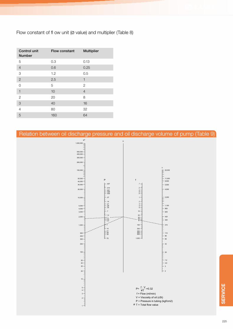
SE
RV
ICE
Flow constant of fl ow unit (ø value) and multiplier (Table 8)
Relation between oil discharge pressure and oil discharge volume of pump (Table 9)
Control unit
Number
Flow constant Multiplier
5 0.3 0.13
4 0.6 0.25
3 1.2 0.5
2 2.5 1
0 5 2
1 10 4
2 20 8
3 40 16
4 80 32
5 160 64
1,000,000
500,000
400,000
300,000
200,000
100,000
50,000
40,000
30,000
20,000
10,000
5,000
4,000
3,000
2,000
1,000
500
400
300
200
100
50
40
30
20
10
5
4
3
2
1
.007
.014
.021
.028
.035
.07
.14
.21
.35
.7
1.4
3.5
7
14
35
70
2128
2.8
.28
.1
.2
.3
.4
.5
1
2
345
10
20
30
100
200
300400500
1,000
40
V
22,000
11,000
8,500
5,500
4,500
2,200
1,100
850
625
420
320
215
110
85
65
42
20
7.2
3.9
3
2
XφT
50
2.1
P= ×0.32f · VøT
f = Flow (ml/min)
V = Viscosity of oil (cSt)
P = Pressure in tubing (kgf/cm2)
T = Total flow valueø
P f
225

SERVICE
1. In general, the main size tubing used is 4 mm O.D., 6 mm O.D, or 8 mm O.D. In most cases the secondary tubing is 4 mm.
2. The tubing is made of copper, steel or nylon.
3. When cutting the tubing, always use a tubing cutter and cut at a 90 degree angle. After cutting, remove all burs.
Be sure not to flatten or damage the tubing.
4. When installing the tubing, always use compression fittings as described in the drawings below.
5. For type HSA/CSA, type HJB/CJB see the illustrations on the right for making tubing connections.
6. For making junction connections, see the illustrations.
106251206251
106254206254
106254206254
4 O.D.6 O.D.
106252206252
4 O.D.6 O.D.
Standard compression connections
■ Compression nut used example
Tubing Tubing
Compression nut
Compression sleeve
■ Compression bushing used example
Compression bushing
Compression sleeve
■ Nylon tube used example
Compression sleeve
Compression bushing or compression nut
Tubing insert
Nylon tubing
Install the tube insert into the end of the nylon
tube. Install the compression bushing or nut,
followed by the compression sleeve and
insert assembly into or onto the the
appropriate compression connection. Tighten
the compression bushing or nut so that the
compression sleeve tightens onto the tubing
wall.
System Installation
Tubing connection method
226

SE
RV
ICE
(HJB/CJB)
Junction type
(HSA/CSA)
Standard type
RC1/8
(ø6)
(HSA/CSAMode)
106101 ■ Connector used exampleElbow connector
Flow unit/control unit
■ Main piping connecting example
Junction
Compression sleeve
Compression sleeve
Compression bushing
Main tubing
Main tubing
Compression bushingStraight adapter
106071
106001
106254
106251
106253
■ Adapter used example
Straight adapter
Elbow connector
Compressionbushing
Compression sleeve
Compression nut
227

SERVICE
Table 21
Mark Product combination
Number of rotations
after
„hand tightening“
Tourque N·m
Number of rotations
after hitting a
sheet side
4mm
Compression
Bushing for
piping
A
Nylon tubing
(with tube insert),
Aluminum-pipe
2/3 3.4 1/6 – 1/4
BCopper pipe,
Steel Pipe2/3 3.9 1/6 – 1/4
6mm
Compression
Bushing for
piping
CNylon tubing
(with tube insert)2/3 3.4 1/6 – 1/4
DCopper pipe,
Steel Pipe2/3 3.9 1/6 – 1/4
8mm
Compression
Bushing for
piping
ENylon tubing
(with tube insert)2/3 6.9 1/6 – 1/4
F Copper pipe 2/3 11.8 1/6 – 1/4
G Steel pipe 2/3 13.7 1/6 – 1/4
4mm
Compression Nut
for piping
HNylon tubing
(with tube insert)2/3 2.5 1/6 – 1/4
I Copper pipe 2/3 2.9 1/6 – 1/4
J Steel pipe 2/3 3.9 1/6 – 1/4
6mm
Compression Nut
for piping
KNylon tubing
(tube insert is entered)2/3 4.9 1/6 – 1/4
LCopper tubing,
Steel tubing2/3 5.9 1/6 – 1/4
Flow unit Q Junctions 1/2 5.9 – 7.8 1/6 – 1/4
SP valve
RSealing washer SW
iron and aluminium (Plug)1/6 9.8 –
S
Outlet check, straight
adapter (dischagre port);
with compression sleeves
2/3 9.8 –
Others
T
Tubing parts (Rc 1/8);
zinc, aluminium, brass
and iron, brass
2.5 – 3 6.9 –
UTubing parts (Rc 1/8);
iron and iron1 8.8 –
V
ø6 high pressure fitting,
fitting body and nut
sleeve, steel tubing
1.25 19.6 –
W
ø 8 high pressure fitting,
fitting body and nut
sleeve, steel tubing
1.25 29.4 –
Installation
Tightening torque table
228

➔ TROUBLESHOOTING
229

SERVICE
Troubleshooting
LHL + Grease-System
No grease coming out of the pump
No pressure rise in the main line
No grease coming out of the valves
• Low grease level — change grease cartridge
• Change in grease consistency, too thick to pump — check grease grade and temperature
• Only sucks air — Crack air bleeding plug to purge air from pump
• Motor turns in wrong direction — check motor wiring connections
• Solenoid (if equipped) not actuating — Replace solenoid and confirm wiring polarity is correct
• Relief valve is dirty — clean relief valve
• Air in tubing — loosen closure plug at the furthest point and run the pump to expel the air
• Check for incorrect connections in the system — repair any problems
• Tubing damage — repair or replace damaged tubing
• Pressure relief valve is not working — for EGH model (manual relief) check valve position; for automatic relief model —
check valve
• Valve is clogged — replace the valve
• The secondary line (from valve to bearing) has no grease in it — fill with grease at initial installation
• Air coming from suction side — low grease level in the reservoir, fill reservoir with correct grade of grease
• Tubing damage — repair or replace tubing
• Wrong wiring connections — check motor wiring
• Circuit protector is in off position — press the reset button
• Pump on time is not set correctly — check discharge setting
• Grease level is too low — change cartridge grease
• Reset button has not been pressed — press the reset button
Air in main line
Pump is not running, but indication light is on
Trouble indication light is on
Can not turn off the trouble indication light
230

SE
RV
ICE
Oil System
• Reset button has not been pressed— press the reset button
• Oil has not been added to reservoir — fill reservoir with correct oil
• Pump did not reach the specified pressure — consult with us
Pump not discharging oil
No pressure increase in the main line
Air in system
No oil passing thru flow or control unit
The pump is not running, but light is on (if equipped)
Reservoir has proper oil level, but oil level warning is on
Cannot turn off trouble light (if equipped)
• Check for broken Tubing or leaking fittings — Replace as needed
• Ball seat of relief valve is clogged — clean relief valve
• Air in tubing — check for leaks, open system at furthest point and run pump to remove air
• Improper selection of control unit or flow unit — check manufacturers recommendation and replace with correct unit
• Improper pressure setting (gear pump) — adjust by-pass setting
• Damaged “O”ring on the piston (piston pump)— replace
• Oil leaking from junction — tighten fitting properly or replace tube fitting
• Oil level in the reservoir is too low — fill with correct oil and follow above procedure for removing air
• Damaged tubing — replace damaged tubing
• Check flow direction on hex of flow or control unit — if incorrect, replace with correct unit
• Check for clogged unit — replace unit
• Motor is wired wrong — check motor wiring
• Circuit protector is in off position — press reset button
Trouble indication light is on (if equipped)• Discharge time is set too short, pump is not reaching proper pressure — check time setting
• The oil level switched because of low oil level — fill reservoir with correct oil
• Low oil level in reservoir — add currently used oil
• Clogged suction filter — clean or change oil filter and clean reservoir
• Check for incorrect oil — if not correct, purge complete system, clean reservoir and fill with correct oil
• Motor turns in wrong direction — check motor wiring
• Damaged tubing within the pump — fi x or replace
• By-pass valve out of adjustment — adjust by-pass valve
• Check inlet and outlet check valve — disassemble and clean
Note: Never add a check valve to a pump that was not originally intended
• Mistake on A, B contacts of oil level switch — consult with us
231

INDEX
Model Part No. Page
A
AB31013 229438 72
AB31013 229439 72
AB31013 229440 72
ACM-II-1 102484 138
ACM-II-2 102486 138
AM-1 102054 140
AM-2 102050 140
AMI-1000-3 202275 92
AMI-1000S-1 202103 92
AMI-1000S-2 202101 92
AMI-300S-1 202033 92
AMI-300S-2 202034 92
AMO-II-150S-1 202067 90
AMO-II-150S-1-3 202069 90
AMO-II-150S-1-P 202071 90
AMO-II-150S-1-P-3 202073 90
AMO-II-150S-2 202068 90
AMO-II-150S-2-3 202070 90
AMO-II-150S-2-P 202072 90
AMO-II-150S-2-P-3 202074 90
AMO-III DS-1 285301 88
AMO-III DS-1-3 285303 88
AMO-III DS-2 285302 88
AMO-III DS-2-3 285304 88
AMR-III DS-1 112141 126
AMR-III DS-1-3 112143 126
AMR-III DS-2 112142 126
AMR-III DS-2-3 112144 126
AMS-1-1 102401 136
AMS-1-1L 102403 136
AMS-1-2 102402 136
AMS-1-2L 102404 136
AMS-15-1 102416 136
AMS-15-1L 102418 136
AMS-15-2 102417 136
AMS-15-2L 102419 136
AMS-3-1 102405 136
AMS-3-1L 102407 136
AMS-3-2 102406 136
AMS-3-2L 102408 136
AMS-6-1 102489 136
AMS-6-1L 112094 136
AMS-6-2 102490 136
AMS-6-2L 112095 136
AMZ-III-1 285017 84
AMZ-III-1-3 285024 84
AMZ-III-2 285016 84
AMZ-III-2-3 285023 84
AMZ-III-100SL-18LP 285224 84
AMZ-III-100SL-18LP 285426 84
AMZ-III-23 285433 84
AT-4 106811 <?>
AT-6 206811 <?>
AW20-01BG 229570 72
B
BP-1 540170 <?>
BP-2 290038 <?>
BP-8 206274 <?>
BP-10 206275 <?>
Model Part No. Page
BP-12 206276 <?>
BP-14 207276 <?>
BPP 619802 36
BPY 530911 74
BT-102(4) 101112 14
BT-102(8) 101111 14
BT-4 106803 <?>
BT-6 218007 <?>
C
CB-4-10 106252 182
CB-4-8 106253 182
CB-4-B 166253 182
CB-6 206252 182
CB-6-B 166255 182
CB-8 207252 182
CBT-SU03-2 249150 63
CJB-0 105215 142
CJB-02 105214 142
CJB-03 105213 142
CJB-04 105212 142
CJB-05 105211 142
CJB-1 105216 142
CJB-2 105217 142
CJB-3 105218 142
CJB-4 105219 142
CJB-5 105220 142
CN-4 106251 182
CN-4-B 166268 182
CN-6 206251 182
CP-4 106255 <?>
CP-6 206255 <?>
CP-8 207255 <?>
CS-4 106254 182
CS-6 206254 182
CS-8 207254 182
CSA-0 105205 142
CSA-02 105204 142
CSA-03 105203 142
CSA-04 105202 142
CSA-05 105201 142
CSA-1 105206 142
CSA-2 105207 142
CSA-3 105208 142
CSA-4 105209 142
CSA-5 105210 142
CT-4 106821 <?>
CT-6 218015 <?>
CT-8 206823 <?>
CTA-0 105225 142
CTA-02 105224 142
CTA-03 105223 142
CTA-04 105222 142
CTA-05 105221 142
CTA-1 105226 142
CTA-2 105227 142
CTA-3 105228 142
CTA-4 105229 142
CTA-5 105230 142
CTB-0 105255 142
CTB-02 105254 142
Model Part No. Page
CTB-03 105253 142
CTB-04 105252 142
CTB-05 105251 142
CTB-1 105256 142
CTB-2 105257 142
CTB-3 105258 142
CTB-4 105259 142
CTB-5 105260 142
CTC-0 105245 142
CTC-02 105244 142
CTC-03 105243 142
CTC-04 105242 142
CTC-05 105241 142
CTC-1 105246 142
CTC-2 105247 142
CTC-3 105248 142
CTC-4 105249 142
CTC-5 105250 142
CTD-0 105235 142
CTD-02 105234 142
CTD-03 105233 142
CTD-04 105232 142
CTD-05 105231 142
CTD-1 105236 142
CTD-2 105237 142
CTD-3 105238 142
CTD-4 105239 142
CTD-5 105240 142
CTG-0 105275 149
CTG-02 105274 149
CTG-03 105273 149
CTG-04 105272 149
CTG-05 105271 149
CTG-1 105276 149
CTG-2 105277 149
CTG-3 105278 149
CTG-4 105279 149
CTG-5 105280 149
CTH-0 105285 149
CTH-02 105284 149
CTH-03 105283 149
CTH-04 105282 149
CTH-05 105281 149
CTH-1 105286 149
CTH-2 105287 149
CTH-3 105288 149
CTH-4 105289 149
CTH-5 105290 149
CTK-0 105265 149
CTK-02 105264 149
CTK-03 105263 149
CTK-04 105262 149
CTK-05 105261 149
CTK-1 105266 149
CTK-2 105267 149
CTK-3 105268 149
CTK-4 105269 149
CTK-5 105270 149
CTL-0 105295 149
CTL-02 105294 149
Model Part No. Page
CTL-03 105293 149
CTL-04 105292 149
CTL-05 105291 149
CTL-1 105296 149
CTL-2 105297 149
CTL-3 105298 149
CTL-4 105299 149
CTL-5 105300 149
CTU-0 105325 149
CTU-02 105324 149
CTU-03 105323 149
CTU-04 105322 149
CTU-05 105321 149
CTU-1 105326 149
CTU-2 105327 149
CTU-3 105328 149
CTU-4 105329 149
CTU-5 105330 149
D
DB-3 226403 <?>
DB-5 226405 <?>
DB-6 226406 <?>
DH-500 226710 <?>
DH-1000 226711 <?>
DH-1500 226712 <?>
DH-2000 226713 <?>
DH-2500 226714 <?>
DVR-1 619041 106
DVR-2 619042 106
DVR-3 619043 106
DVR-4 619044 106
DVR-5 619045 106
DVR-6 619046 106
DVR-7 619047 106
DVR-8 619048 106
DVR-9 619049 106
DVR-10 619050 106
E
E2E-X2E1 733225 71
E2F-X2E1 730797 71
E2F-X2Y1 730721 71
E61-BD 250103 <?>
E61-SC 250113 198
E62-BD 290277 <?>
E62-SC 290184 198
E81-BD 250123 <?>
E81-SC 250133 198
E82-BD 290246 <?>
E82-SC 290043 198
EA4-1F 106031 190
EA4-20 106021 190
EA4-25 106022 190
EA4-2R 206091 190
EA4-30 106023 190
EA4-40 106024 190
EA4-50 106025 190
EA4-60 106026 190
EA4-6A 106076 190
EA4-6AS 106074 190
EA4-6B 106075 190
149
232

Model Part No. Page
EA4-8A 106029 190
EA4-8B 166054 190
EA4-8T 106028 190
EA4-8 Taper 106037 190
EA4-US 166036 190
EA6-22 206092 190
EA6-6AS 166048 190
EA6-U 166040 190
EAR-4 106071 190
EC1-20 106107 192
EC1-22 106101 192
EC1-25 106102 192
EC1-30 106103 192
EC1-40 106104 192
EC1-50 106105 192
EC1-60 106106 192
EC-6A 106181 192
EC-8A 106182 192
ECC-22 106121 192
ECC-25 106122 192
ECC-30 106123 192
ECC-40 106124 192
ECC-50 106125 192
ECC-60 106126 192
ECM-5A 106183 192
ECM-6A 106185 192
ECM-6B 106184 192
ECM-6BL 106192 192
ECMG-6ALL 106382 196
ECMG-6BL 166039 196
EGH-2C 103780 32/52
EGH-3P 103783 32/52
EGH-4C 103782 32/52
EGM-10S-4-2C 103809 30
EGM-10S-4-4C 103810 30
EGM-10S-4-7C 103811 30
EGMII-10S-4-7CL 103937 24
EGMII-10S-4-7CLFB 103938 24
EGMII-10T-4-7CL 103947 24
EGMII-8S-4-7CLFB-LHL 103936 24
EGMII-8S-4-7CL-LHL 103935 24
EGME-10T-4-2C 103902 56
EGME-10T-4-7C 103911 56
EGMEII-10S-4-7CL 103922 26
EGMEII-10S-4-7CLFB 103923 26
EGMEII-10T-4-7CL 103932 26
EGMEII-8S-4-7CLFB-LHL103921 26
EGMEII-8S-4-7CL-LHL103920 26
ETE-4A 106911 202
ETE-5A 106913 202
ETE-6A 106916 202
ETE-6B 106915 202
ETE-8B 106917 202
EU6-BD 250104 <?>
EU6-SC 250114 198
EU8-BD 250124 <?>
EU8-SC 250134 198
EX-1 102703 124
EX-1C 102701 124
EX-1L 102707 124
Model Part No. Page
EX-1LC 102705 124
EX-2 102702 124
EX-2C 102700 124
EX-2L 102706 124
EX-2LC 102704 124
EX-5 112828 125
F
F3-4-125 109308 166
F3-6-10 209309 166
F3-6-125 209308 166
F3-6-40 209310 166
F3E-10 259313 166
F3E-125 259311 166
F3E-40 259312 166
F6-BD 250108 <?>
F6-SC 250118 198
F8-BD 250128 <?>
F8-SC 250138 198
FDM-3 225022 156
FDM-5 225023 156
FDM-10 225024 156
FDM-20 225025 156
FDM-30 225026 156
FDM-50 225027 156
FS2-2 249069 63
FS2-4 249053 63
FS2-7 249063 63
FX1-4 109311 166
FX1-6 209311 166
FXE 259304 166
FY20 109313 166
FYE 650147 166
G
GAS-8P 102621 34
GMN-4-8P 102909 48
GMNH-1-4C 103553 50
GMNH-1-7C 103550 50
GMNH-2-4C 103554 50
GMNH-2-7C 103551 50
GMNH-4-4C 103552 50
GMNH-4-7C 103549 50
GMS-4-3P 103624 28
GMS-4-8P 103625 28
GMS-4L-3P 103619 28
GMS-4L-8P 103654 28
GPL-30 209282 41
GPL-30-D 209409 41
GPL-50-D 209403 41
GPL-55 209392 41
GV50-G 500598 74
GV50-R 500649 74
H
HJB-03 105502 134
HJB-02 105008 134
HJB-0 105009 134
HJB-1 105010 134
HJB-2 105011 134
HJB-3 105012 134
HJB-4 105013 134
HJB-5 105014 134
Model Part No. Page
HJBC 109415 202
HSA-03 105501 134
HSA-02 105001 134
HSA-0 105002 134
HSA-1 105003 134
HSA-2 105004 134
HSA-3 105005 134
HSA-4 105006 134
HSA-5 105007 134
HSAC 109407 202
HTA-03 105503 134
HTA-02 105015 134
HTA-0 105016 134
HTA-1 105017 134
HTA-2 105018 134
HTA-3 105019 134
HTA-4 105020 134
HTA-5 105021 134
HTB-03 105506 134
HTB-02 105036 134
HTB-0 105037 134
HTB-1 105038 134
HTB-2 105039 134
HTB-3 105040 134
HTB-4 105041 134
HTB-5 105042 134
HTC-03 105505 134
HTC-02 105029 134
HTC-0 105030 134
HTC-1 105031 134
HTC-2 105032 134
HTC-3 105033 134
HTC-4 105034 134
HTC-5 105035 134
HTD-03 105504 134
HTD-02 105022 134
HTD-0 105023 134
HTD-1 105024 134
HTD-2 105025 134
HTD-3 105026 134
HTD-4 105027 134
HTD-5 105028 134
HTG-03 105508 134
HTG-02 105051 134
HTG-0 105052 134
HTG-1 105053 134
HTG-2 105054 134
HTG-3 105055 134
HTG-4 105056 134
HTG-5 105057 134
HTH-03 105509 134
HTH-02 105058 134
HTH-0 105059 134
HTH-1 105060 134
HTH-2 105061 134
HTH-3 105062 134
HTH-4 105063 134
HTH-5 105064 134
HTK-03 105507 134
HTK-02 105043 134
Model Part No. Page
HTK-0 105044 134
HTK-1 105045 134
HTK-2 105046 134
HTK-3 105047 134
HTK-4 105048 134
HTK-5 105049 134
HTL-03 105510 134
HTL-02 105065 134
HTL-0 105066 134
HTL-1 105067 134
HTL-2 105068 134
HTL-3 105069 134
HTL-4 105070 134
HTL-5 105071 134
HTU-03 105513 134
HTU-02 105072 134
HTU-0 105073 134
HTU-1 105074 134
HTU-2 105075 134
HTU-3 105076 134
HTU-4 105077 134
HTU-5 105078 134
HTUC 109416 202
I
IC-2,5 529008 203
IC-5,5 529009 203
IC-EX 539001 203
J
J02 225008 200
J05 225007 200
J08 225006 200
JV-2 206470 35/95
JV-3 206471 35/95
JV-4D 206464 35/95
JV-6D 206465 35/95
JV-8D 206466 35/95
JV-10D 206467 35/95
JV-12D 206468 35/95
JV-14D 206469 35/95
JV-4S 206472 35/95
JV-5S 206473 35/95
JV-6S 206474 35/95
JV-7S 206475 35/95
JV-8S 206476 35/95
JV-9S 206479 35/95
JV-10S 206543 35/95
JVPA-2D 216021 36
JVPA-4D 216022 36
JVPA-6D 216023 36
JVPA-8D 216024 36
JVPA-10D 216025 36
JVPA-12D 216026 36
JVPA-14D 216027 36
JVPA-16D 216028 36
JVPA-1S 216001 36
JVPA-2S 216002 36
JVPA-3S 216003 36
JVPA-4S 216004 36
JVPA-5S 216005 36
JVPA-6S 216006 36
233

INDEX
Model Part No. Page
JVPA-7S 216007 36
JVPA-8S 216008 36
JVPA-9S 216009 36
JVPA-10S 216010 36
JVPA-11S 216011 36
JVPA-12S 216012 36
JVY 530937 74
K
KBC4-01-F 209503 195
KBC4-02-F 209504 195
KBC4-M6-F 209501 195
KBC4-M6P0,75-F 209502 195
KBC6-01-F 209513 195
KBE4-01-F 209523 195
KBL4-01-FN 209508 195
KBL4-M6-FN 209506 195
KBL6-01-F 209518 195
KEN-M 106673 201
KEN-T 106672 201
KP-4 106231 194
KP-44 106201 194
KP-46 106202 194
KP-4N 106232 194
KP-4R 106291 194
KP-66 106292 194
KP-6R 106293 194
KP-88 207201 194
KPR-4 106221 194
KP-RR 106294 194
KPW-4 106211 194
L
L3-2 103031 128
L3-3 103030 128
L5-3 103051 128
L5-4 103052 128
L5-5 103053 128
L8-L 103111 130
L8-R 103112 130
L20-L 103211 130
L20-R 103212 130
LFL50-H1-7 249322 69
LFL50-H1-4SC 249326 69
LFL180-H1-7 249324 69
LFL180-H1-4 249323 69
LF-53-5 — 153
LF-53-20 — 153
LF-55-5 — 153
LF-55-20 — 153
LF-60-5 — 153
LF-60-20 — 153
LF-65-5 — 153
LF-65-20 — 153
LG-400 252422 69
LHL X-100-2 249139 62
LHL X-100-4 249136 62
LHL X-100-7 249137 62
LHL-300-7 249112 62
LK-8 103401 129
LK-8TL 103402 129
LK-8TR 103403 129
Model Part No. Page
LT-S 103421 94
M
M-A1 521210 122/136
M-A2 521328 122/136
M-B1 521194 122/136
M-B2 521196 122/136
M-C1 521193 120/122
M-C2 521195 120/122
M-D1 520062 120/122
M-D2 520067 120/122
M-E1 520061 120/122
M-E2 520066 120/122
M-F1 520060 120/122
M-F2 520065 120/122
MB-C-3 205201 104
MB-C-5 205200 104
MB-C-10 205199 104
MB-C-20 205198 104
MB-C-30 205197 104
MB-C-50 205196 104
MB-L-3 205195 104
MB-L-5 205194 104
MB-L-10 205193 104
MB-L-20 205192 104
MB-L-30 205191 104
MB-L-50 205190 104
MB-R-3 205207 104
MB-R-5 205206 104
MB-R-10 205205 104
MB-R-20 205204 104
MB-R-30 205203 104
MB-R-50 205202 104
MDP-3E 205896 17
MDP-3HE 205906 17
MDP-3HS 205901 17
MDP-3S 205891 17
MDP-5E 205897 17
MDP-5HE 205907 17
MDP-5HS 205902 17
MDP-5S 205892 17
MDP-10E 205898 17
MDP-10HE 205908 17
MDP-10HS 205903 17
MDP-10S 205893 17
MG2-3 205741 37
MG2-5 205742 37
MG2-10 205743 37
MG2-20 205744 37
MG2-30 205745 37
MG2-50 205746 37
MG2C-10 205733 37
MG2C-20 205734 37
MG2C-3 205731 37
MG2C-5 205732 37
MG2C-30 205735 37
MG2C-50 205736 37
MG2I-5 205822 38
MG2I-10 205823 38
MG2I-20 205824 38
MG2I-30 205825 38
Model Part No. Page
MG2I-50 205826 38
MGLA-10 205515 40
MGLA-20 205518 40
MGLA-30 205588 40
MGLA-50 205589 40
MH-20D-A 222138 151
MH-20D-A-L 222195 151
MIB 559271 150
MIX-1 — 108
MIX-3 — 108
MIX-5 — 108
MIX-10 — 108
MIX-20 — 108
MLZ-CE-A-1 367201 120
MLZ-CE-A-1L 367216 120
MLZ-CE-A-2 367206 120
MLZ-CE-A-2L 367221 120
MLZ-CE-B-1 367202 120
MLZ-CE-B-1L 367217 120
MLZ-CE-B-2 367207 120
MLZ-CE-B-2L 367222 120
MLZ-CE-C-1 367203 120
MLZ-CE-C-1L 367218 120
MLZ-CE-C-2 367208 120
MLZ-CE-C-2L 367223 120
MLZ-CE-D-1 367204 120
MLZ-CE-D-1L 367219 120
MLZ-CE-D-2 367209 120
MLZ-CE-D-2L 367224 120
MLZ-CE-E-1 367205 120
MLZ-CE-E-1L 367220 120
MLZ-CE-E-2 367210 120
MLZ-CE-E-2L 367225 120
MMXL-III CE-1A-1 367001 122
MMXL-III CE-1A-1L 367055 122
MMXL-III CE-1A-2 367007 122
MMXL-III CE-1A-2L 367061 122
MMXL-III CE-1B-1 367002 122
MMXL-III CE-1B-1L 367056 122
MMXL-III CE-1B-2 367008 122
MMXL-III CE-1B-2L 367062 122
MMXL-III CE-1C-1 367003 122
MMXL-III CE-1C-1L 367057 122
MMXL-III CE-1C-2 367009 122
MMXL-III CE-1C-2L 367063 122
MMXL-III CE-1D-1 367004 122
MMXL-III CE-1D-1L 367058 122
MMXL-III CE-1D-2 367010 122
MMXL-III CE-1D-2L 367064 122
MMXL-III CE-1E-1 367005 122
MMXL-III CE-1E-1L 367059 122
MMXL-IIICE-1E-2 367011 122
MMXL-IIICE-1E-2L 367065 122
MMXL-IIICE-1F-1 367006 122
MMXL-IIICE-1F-1L 367060 122
MMXL-IIICE-1F-2 367012 122
MMXL-IIICE-1F-2L 367066 122
MMXL-IIICE-2A-1 367019 122
MMXL-IIICE-2A-1L 367073 122
MMXL-IIICE-2A-2 367025 122
Model Part No. Page
MMXL-IIICE-2A-2L 367079 122
MMXL-IIICE-2B-1 367020 122
MMXL-IIICE-2B-1L 367074 122
MMXL-IIICE-2B-2 367026 122
MMXL-IIICE-2B-2L 367080 122
MMXL-IIICE-2C-1 367021 122
MMXL-IIICE-2C-1L 367075 122
MMXL-IIICE-2C-2 367027 122
MMXL-IIICE-2C-2L 367081 122
MMXL-IIICE-2D-1 367022 122
MMXL-IIICE-2D-1L 367076 122
MMXL-IIICE-2D-2 367028 122
MMXL-IIICE-2D-2L 367082 122
MMXL-IIICE-2E-1 367023 122
MMXL-IIICE-2E-1L 367077 122
MMXL-IIICE-2E-2 367029 122
MMXL-IIICE-2E-2L 367083 122
MMXL-IIICE-2F-1 367024 122
MMXL-IIICE-2F-1L 367078 122
MMXL-IIICE-2F-2 367030 122
MMXL-IIICE-2F-2L 367084 122
MMXL-IIICE-5A-1 367037 122
MMXL-IIICE-5A-1L 367091 122
MMXL-IIICE-5A-2 367043 122
MMXL-IIICE-5A-2L 367097 122
MMXL-IIICE-5B-1 367038 122
MMXL-IIICE-5B-1L 367092 122
MMXL-IIICE-5B-2 367044 122
MMXL-IIICE-5B-2L 367098 122
MMXL-IIICE-5C-1 367039 122
MMXL-IIICE-5C-1L 367093 122
MMXL-IIICE-5C-2 367045 122
MMXL-IIICE-5C-2L 367099 122
MMXL-IIICE-5D-1 367040 122
MMXL-IIICE-5D-1L 367094 122
MMXL-IIICE-5D-2 367046 122
MMXL-IIICE-5D-2L 367100 122
MMXL-IIICE-5E-1 367041 122
MMXL-IIICE-5E-1L 367095 122
MMXL-IIICE-5E-2 367047 122
MMXL-IIICE-5E-2L 367101 122
MMXL-IIICE-5F-1 367042 122
MMXL-IIICE-5F-1L 367096 122
MMXL-IIICE-5F-2 367048 122
MMXL-IIICE-5F-2L 367102 122
MO-1 205070 100
MO-3 205071 100
MO-5 205072 100
MO-10 205073 100
MO-20 205074 100
MO-30 205075 100
MO-50 205076 100
MO-100 205077 100
MO-150 205078 100
MO2-3 205761 100
MO2-5 205762 100
MO2-10 205763 100
MO2-20 205764 100
MO2-30 205765 100
MO2-50 205766 100
234

Model Part No. Page
MO2C-3 205751 100
MO2C-5 205752 100
MO2C-10 205753 100
MO2C-20 205754 100
MO2C-30 205755 100
MO2C-50 205756 100
MOS-1 205300 102
MOS-3 205301 102
MOS-5 205302 102
MOS-10 205303 102
MP0(1)-4 249050 63
MP0(1)-7 249060 63
MU-5 205872 15
MU-5C 205922 15
MU-5N 205912 15
MU-10 205873 15
MU-10C 205923 15
MU-10N 205913 15
MU-20 205874 15
MU-20C 205924 15
MU-20N 205914 15
MU-30 205935 15
MU-30C 205925 15
MU-30N 205915 15
MU-50 205936 15
MU-50C 205926 15
MU-50N 205916 15
MU-BP 619840 16
MU-SC 619841 16
MUJ-1S 216101 16
MUJ-2D 216121 16
MUJ-2S 216102 16
MUJ-3S 216103 16
MUJ-4D 216122 16
MUJ-4S 216104 16
MUJ-5S 216105 16
MUJ-6D 216123 16
MUJ-6S 216106 16
MUJ-7S 216107 16
MUJ-8D 216124 16
MUJ-8S 216108 16
MUJ-9S 216109 16
MUJ-10D 216125 16
MUJ-10S 216110 16
MUJ-12D 216126 16
MUJ-14D 216127 16
MUJ-16D 216128 16
N
N6-BD 250109 199
N6-SC 250119 198
N8-BD 250129 199
N8-SC 250139 198
NA-05 106974 200
NA-08 106975 200
NT-4 106801 184
NT-4H 106806 184
NT-6 218005 184
NT-6H 218006 184
NT-8 218003 184
NYB 109405 196
Model Part No. Page
NYS 109406 196
O
OA-I — 174
OC-1 549006 209
OC-2 549005 209
OC-3 529432 209
OC-4 529409 209
OFS-A 106651 171
OFS-B 106652 171
OS-1 521037 209
OTE-4 106373 201
OTE-6 206155 201
OTS-4 106369 201
OTS-6 206152 201
P
P-102(B) 101006 12
P-102(BK) 101002 12
P-102F2(B) 101086 12
P-102F2(BK) 101082 12
P-107(B) 101007 12
P-107(BK) 101003 12
P-107F2(B) 101087 12
P-107F2(BK) 101083 12
P-202(B) 101036 12
P-202(BK) 101032 12
P-207(B) 101037 12
P-207(BK) 101033 12
P-202F(B) 101046 12
P-202F(BK) 101042 12
P-207F(B) 101047 12
P-207F(BK) 101043 12
P3-C JC0005 75
PB-7 109166 169
PB-15 109167 169
PB-35 209136 169
PB-35B 209137 169
PB-50 109161 169
PB-50B 109162 169
PB100 109146 74
PB250 109147 74
PB250B 209288 74
PC-4-1 106301 191
PC-4-1L 106311 191
PC-4-1LL 106321 191
PC-4-2 106302 191
PC-4-2L 106312 191
PC-4-2LL 106322 191
PC-4-3 106303 191
PC-4-3L 106313 191
PC-4-3LL 106323 191
PC-4-4 106304 191
PC-4-4L 106314 191
PC-4-4LL 106324 191
PC-4-5 106305 191
PC-4-5L 106315 191
PC-4-5LL 106325 191
PC-4-6 106306 191
PC-4-6L 106316 191
PC-6-1 206301 191
PC-6-1L 206311 191
Model Part No. Page
PC-6-1LL 206321 191
PC-6-2 206302 191
PC-6-2L 206312 191
PC-6-2LL 206322 191
PC-6-3 206303 191
PC-6-3L 206313 191
PC-8-1 207301 191
PC-8-2 207302 191
PC-10-1 208301 191
PGC-4 619322 199
PGC-6 619434 199
PH-60 403010 193
PH-60B 403020 193
PH-N 403001 193
PH-NB 403007 193
PH-S 403002 193
PH-SB 403008 193
PH-SE 403003 193
PJ-6D 106411 139
PJ-8D 106412 139
PJ-10D 106413 139
PJ-12D 106414 139
PJ-14D 106415 139
PJ-16D 106416 139
PJ-2 106421 138
PJ2-6 206452 105
PJ-2F 106424 138
PJ-3 106420 138
PJ3-6 206453 105
PJ-3F 106425 138
PJ-4 106423 138
PJ4-6 206454 105
PJ4S-6 206461 105
PJ-4S 106401 139
PJ-5S 106402 139
PJ-6S 106403 139
PJ-7S 106404 139
PJ-8S 106405 139
PJ-9S 106406 139
PJ-10S 106407 139
PJ-12S 106408 139
PM-8S 102660 86/148
PM-8S-L 102754 86/148
PP 109102 169
PS-A011 209177 170
PS-A014 209203 170
PS-A110 209205 170
PS-A115 209176 170
PS-A150 209178 170
PS-A170 209171 170
PS-A180 209204 170
PS-B014 209172 170
PS-B015 209175 170
PS-B021 209174 170
PS-B150 209173 170
PS-B170 209170 170
PSC 207202 213
PUY-6 539291 74
PUY-8 539292 74
PV-1 206481 103
Model Part No. Page
PV-2 206482 103
PV-3 206483 103
PV-4 206484 103
PV-5 206485 103
PV-6 206486 103
PV-7 206487 103
PV-8 206489 103
PV-2D 206491 103
PV-4D 206492 103
PV-6D 206493 103
PV-8D 206494 103
PV-10D 206495 103
PV-12D 206496 103
PVS-2D 206554 104
PVS-4D 206557 104
PVS-2S 206572 104
PVS-3S 206573 104
PVS-4S 206574 104
PVS-5S 206575 104
PVS-6S 206576 104
PVS-7S 206577 104
PVS-8S 206578 104
R
RF-250 109317 166
RTY 539310 74
RV-0,5 519003 209
RV-0,8 509002 209
RV-2,5 519002 209
S
S61-BD 250101 205
S61-SC 250111 204
S62-BD 290219 205
S62-SC 290191 204
S81-BD 250121 205
S81-SC 250131 204
S82-BD 290245 205
S82-SC 290190 204
SA-4K 106011 194
SA4-10A 106089 195
SA4-12A 206012 195
SA4-16 106001 194
SA4-20 106002 194
SA4-25 106003 194
SA4-2R 106091 195
SA4-30 106004 194
SA4-35 106005 194
SA4-5A 106082 195
SA4-6A 106084 195
SA4-6B 106085 195
SA4-7A 106087 195
SA4-8A 106088 195
SA4-U 106099 195
SA6-12A 206011 195
SA6-20 206001 194
SA6-2R 206081 195
SA6-6A 106094 195
SA6-8T 106095 195
SA6-U 106353 195
SA8-28 194001 194
SAB-30 259353 166
235

INDEX
Model Part No. Page
SAB-40 259354 166
SAB-50 259355 166
SAB-70 259358 166
SAG4-6B 106366 202
SAR-4 106061 194
SAR-6 206223 194
SAT-1R 106081 194
SAT-6A 106062 194
SAT-6B 106065 194
SATG-6B 106064 202
SB-N 225001 158
SB-R 225002 158
SC-10A 106177 198
SC-4 106174 198
SC-6A 106154 198
SC-8T 106147 198
SC1-20 106141 198
SC1-25 106142 198
SC1-30 106143 198
SC1-40 106144 198
SC1-50 106145 198
SC1-60 106146 198
SC2 206141 198
SCP 619803 102
SCR 106151 198
SCY 550130 74
SDM-72 — 162
SF-01 489001 209
SF-05 489005 209
SF-07 489007 209
SF-08 489008 209
SF-10 489010 209
SF-11 489011 209
SF-12 489012 209
SF-13 489013 209
SF-A 500324 209
SF-D 106520 207
SF-L3 540727 209
SF-L5 . LK 540562 209
SF-N 106511 207
SF-R 106505 207
SF-RA 106506 207
SFB-4 106501 207
SFB-DN 106521 207
SFB-N 106510 207
SFB-R 106502 207
SFB-RA 106503 207
SFB-RL 106504 207
SJ-265 225011 158
SJ-410 225012 158
SJ-500 225013 158
SJ-600 225016 158
SP-10 205543 64
SP-10K 205533 64
SP-10S 205538 64
SP-12 205544 64
SP-12K 205534 64
SP-12S 205539 64
SP-4 205540 64
SP-4K 205530 64
Model Part No. Page
SP-6 205541 64
SP-6K 205531 64
SP-6S 205536 64
SP-8 205542 64
SP-8K 205532 64
SP-8S 205537 64
SPA-4 166005 64
SPA-6 619780 64
SPB 611785 64
SPC 611664 64
SPN 611784 64
SPS 611695 64
SPS-8T-0,1-0.05-1/4 109181 171
SPS-8T-0,25-0,2-1/4 109182 171
SPS-8T-0,4-0,35-1/4 109183 171
SPS-8T-1,2-0,9-1/4 109184 171
SPS-8TP-1,7-1,4-3/8 209181 171
Mounting panel vertic. 531155 72
Mounting panel horiz. 531187 72
ST-10Z 206837 190
ST-4Z 218011 190
ST-6Z 218012 190
ST-8Z 206836 190
STE-4A 106931 208
STE-5A 106933 208
STE-6A 106936 208
STE-6B 106935 208
STE-8B 106937 208
SVL 109412 206
SW-10 207611 <?>
SW-12 207612 <?>
SW-14 207613 <?>
SW-8 207610 <?>
SWY 530910 74
SYB 109417 203
SYS 109418 203
T
T-2LP 254104 176
T-4LP 254106 176
T-8LP 254102 177
T-18LP 609005 177
T-20L-AB 104401 179
T-20L-AF 104301 179
T-20L-HB 104403 179
T-20L-HF 104303 179
T-20L-KB 104402 179
T-20L-KF 104302 179
T-30L-AOB 104426 180
T-30L-AOF 104326 180
T-30L-LAB 104411 180
T-30L-LAF 104311 180
T-30L-LHB 104418 180
T-30L-LHF 104318 180
T-30L-LKB 104416 180
T-30L-LKF 104316 180
T-30L-LXB 104413 180
T-30L-LXF 104313 180
T-30L-OLAB 104420 180
T-30L-OLAF 104320 180
T-30L-OLHB 104424 180
Model Part No. Page
T-30L-OLHF 104324 180
T-30L-OLKB 104422 180
T-30L-OLKF 104322 180
T-30L-ORAB 104421 180
T-30L-ORAF 104321 180
T-30L-ORHB 104425 180
T-30L-ORHF 104325 180
T-30L-ORKB 104423 180
T-30L-ORKF 104323 180
T-30LP 609583 178
T-30LP-LX 104657 178
T-30LP-RX 104658 178
T-30L-RAB 104412 180
T-30L-RAF 104312 180
T-30L-RHB 104419 180
T-30L-RHF 104319 180
T-30L-RKB 104417 180
T-30L-RKF 104317 180
T-30L-RXB 104414 180
T-30L-RXF 104314 180
T-40L-AOB 104456 182
T-40L-AOF 104356 182
T-40L-LAB 104441 182
T-40L-LAF 104341 182
T-40L-LHB 104448 182
T-40L-LHF 104348 182
T-40L-LKB 104446 182
T-40L-LKF 104346 182
T-40L-LXB 104443 182
T-40L-LXF 104343 182
T-40L-OLAB 104450 182
T-40L-OLAF 104350 182
T-40L-OLHB 104454 182
T-40L-OLHF 104354 182
T-40L-OLKB 104452 182
T-40L-OLKF 104352 182
T-40L-ORAB 104451 182
T-40L-ORAF 104351 182
T-40L-ORHB 104455 182
T-40L-ORHF 104355 182
T-40L-ORKB 104453 182
T-40L-ORKF 104353 182
T-40L-RAB 104442 182
T-40L-RAF 104342 182
T-40L-RHB 104449 182
T-40L-RHF 104349 182
T-40L-RKB 104447 182
T-40L-RKF 104347 182
T-40L-RXB 104444 182
T-40L-RXF 104344 182
T-80L-AOB 104486 184
T-80L-AOF 104386 184
T-80L-LAB 104471 184
T-80L-LAF 104371 184
T-80L-LHB 104478 184
T-80L-LHF 104378 184
T-80L-LKB 104476 184
T-80L-LKF 104376 184
T-80L-LXB 104473 184
T-80L-LXF 104373 184
Model Part No. Page
T-80L-OLAB 104480 184
T-80L-OLAF 104380 184
T-80L-OLHB 104484 184
T-80L-OLHF 104384 184
T-80L-OLKB 104482 184
T-80L-OLKF 104382 184
T-80L-ORAB 104481 184
T-80L-ORAF 104381 184
T-80L-ORHB 104485 184
T-80L-ORHF 104385 184
T-80L-ORKB 104483 184
T-80L-ORKF 104383 184
T-80L-RAB 104472 184
T-80L-RAF 104372 184
T-80L-RHB 104479 184
T-80L-RHF 104379 184
T-80L-RKB 104477 184
T-80L-RKF 104377 184
T-80L-RXB 104474 184
T-80L-RXF 104374 184
T6-BD 250105 205
T6-SC 250115 204
T8-BD 250125 205
T8-SC 250135 204
TA 106431 137
TA4-1F 106041 197
TAF-15 109155 169
TAF-50 209117 169
TAF-7 109154 169
TAR-1F 106051 197
TB 106432 137
TC 106433 137
TCF 106171 199
TCR 106161 199
TD 106434 137
TG 106435 137
TH 106436 137
TI-4 106271 188
TI-6 206271 188
TI-8 207271 188
TK 106437 137
TL 106438 137
U
U6-BD 250102 205
U6-SC 250112 204
U8-BD 250122 205
U8-SC 250132 204
V
VACUUMER 222301 76
VBP-1 112740 152
VBP-1-3 112752 152
VBP-1-G 112746 152
VBP-1-G-3 112762 152
VBP-2 112741 152
VBP-2-3 112753 152
VBP-2-G 112747 152
VBP-2-G-3 112763 152
VBP-3 112742 152
VBP-3-3 112754 152
VBP-3-G 112748 152
236

Model Part No. Page
VBP-3-G-3 112764 152
VBP-4-3 112755 152
VBP-4-G-3 112765 152
VBP-5-3 112756 152
VBP-5-G-3 112766 152
VOA-365 112786 156
VUC-II 300460 72
VX3114-1G 229548 78
VX3114-2G 229549 78
VX3114-5G 229550 78
W
W-105-02 109704 164
W-105-02(B) 109705 164
W-105B 109706 164
W-105B(B) 109707 164
WL-100-U30BS 109221 164
WL-105-U32BS 109222 164
WL-120-U50BS 109223 164
WL-150-U35BS 109224 164
WL-150-U50BS 109225 164
WL-160-U80BS 109226 164
WL-190-U80BS 109227 164
WL-210-U50BS 109228 164
WTL-100-U30BS 109271 164
WTL-105-U32BS 109272 164
WTL-120-U50BS 109273 164
WTL-150-U35BS 109274 164
WTL-150-U50BS 109275 164
WTL-160-U80BS 109276 164
WTL-190-U80BS 109277 164
WTL-210-U50BS 109278 164
X
XP-0 250036
Y
YMT-3-1T-6 103990 52
YMT-3-1T-8 103992 52
YMT-5-1T-6 103991 52
YMT-5-1T-8 103993 52
YMT-C-E-S-AC 300421 53
YMT-TBOX 300423 53
YS2-4 249106 69
YS2-7 249107 69
Z
ZE-6B 166045 203
ZE-8A 106027 203
237

INDEX
Part No. Model Page
101002 P-102(BK) 18
101003 P-107(BK) 18
101006 P-102(B) 18
101007 P-107(B) 18
101032 P-202(BK) 18
101033 P-207(BK) 18
101036 P-202(B) 18
101037 P-207(B) 18
101042 P-202F(BK) 18
101043 P-207F(BK) 18
101046 P-202F(B) 18
101047 P-207F(B) 18
101082 P-102F2(BK) 18
101083 P-107F2(BK) 18
101086 P-102F2(B) 18
101087 P-107F2(B) 18
101111 BT-102(8) 20
101112 BT-102(4) 20
102050 AM-2 146
102054 AM-1 146
102401 AMS-1-1 142
102402 AMS-1-2 142
102403 AMS-1-1L 142
102404 AMS-1-2L 142
102405 AMS-3-1 142
102406 AMS-3-2 142
102407 AMS-3-1L 142
102408 AMS-3-2L 142
102416 AMS-15-1 142
102417 AMS-15-2 142
102418 AMS-15-1L 142
102419 AMS-15-2L 142
102484 ACM-II-1 144
102486 ACM-II-2 144
102489 AMS-6-1 142
102490 AMS-6-2 142
102621 GAS-8P 40
102660 PM-8S 92/154
102700 EX-2C 130
102701 EX-1C 130
102702 EX-2 130
102703 EX-1 130
102704 EX-2LC 130
102705 EX-1LC 130
102706 EX-2L 130
102707 EX-1L 130
102754 PM-8S-L 92/154
102909 GMN-4-8P 54
103030 L3-3 134
103031 L3-2 134
103051 L5-3 134
103052 L5-4 134
103053 L5-5 134
103111 L8-L 136
103112 L8-R 136
103211 L20-L 136
103212 L20-R 136
103401 LK-8 135
103402 LK-8TL 135
103403 LK-8TR 135
Part No. Model Page
103421 LT-S 100
103549 GMNH-4-7C 56
103550 GMNH-1-7C 56
103551 GMNH-2-7C 56
103552 GMNH-4-4C 56
103553 GMNH-1-4C 56
103554 GMNH-2-4C 56
103619 GMS-4L-3P 34
103624 GMS-4-3P 34
103625 GMS-4-8P 34
103654 GMS-4L-8P 34
103780 EGH-2C 38/58
103782 EGH-4C 38/58
103783 EGH-3P 38/58
103809 EGM-10S-4-2C 36
103810 EGM-10S-4-4C 36
103811 EGM-10S-4-7C 36
103902 EGME-10T-4-2C 62
103911 EGME-10T-4-7C 62
103920 EGMEII-8S-4-7CL-LHL 32
103921 EGMEII-8S-4-7CLFB-LHL 32
103922 EGMEII-10S-4-7CL 32
103923 EGMEII-10S-4-7CLFB 32
103932 EGMEII-10T-4-7CL 32
103935 EGMII-8S-4-7CL-LHL 30
103936 EGMII-8S-4-7CLFB-LHL 30
103937 EGMII-10S-4-7CL 30
103938 EGMII-10S-4-7CLFB 30
103947 EGMII-10T-4-7CL 30
103990 YMT-3-1T-6 52
103991 YMT-5-1T-6 52
103992 YMT-3-1T-8 52
103993 YMT-5-1T-8 52
104301 T-20L-AF 179
104302 T-20L-KF 179
104303 T-20L-HF 179
104311 T-30L-LAF 180
104312 T-30L-RAF 180
104313 T-30L-LXF 180
104314 T-30L-RXF 180
104316 T-30L-LKF 180
104317 T-30L-RKF 180
104318 T-30L-LHF 180
104319 T-30L-RHF 180
104320 T-30L-OLAF 180
104321 T-30L-ORAF 180
104322 T-30L-OLKF 180
104323 T-30L-ORKF 180
104324 T-30L-OLHF 180
104325 T-30L-ORHF 180
104326 T-30L-AOF 180
104341 T-40L-LAF 182
104342 T-40L-RAF 182
104343 T-40L-LXF 182
104344 T-40L-RXF 182
104346 T-40L-LKF 182
104347 T-40L-RKF 182
104348 T-40L-LHF 182
104349 T-40L-RHF 182
104350 T-40L-OLAF 182
Part No. Model Page
104351 T-40L-ORAF 182
104352 T-40L-OLKF 182
104353 T-40L-ORKF 182
104354 T-40L-OLHF 182
104355 T-40L-ORHF 182
104356 T-40L-AOF 182
104371 T-80L-LAF 184
104372 T-80L-RAF 184
104373 T-80L-LXF 184
104374 T-80L-RXF 184
104376 T-80L-LKF 184
104377 T-80L-RKF 184
104378 T-80L-LHF 184
104379 T-80L-RHF 184
104380 T-80L-OLAF 184
104381 T-80L-ORAF 184
104382 T-80L-OLKF 184
104383 T-80L-ORKF 184
104384 T-80L-OLHF 184
104385 T-80L-ORHF 184
104386 T-80L-AOF 184
104401 T-20L-AB 179
104402 T-20L-KB 179
104403 T-20L-HB 179
104411 T-30L-LAB 180
104412 T-30L-RAB 180
104413 T-30L-LXB 180
104414 T-30L-RXB 180
104416 T-30L-LKB 180
104417 T-30L-RKB 180
104418 T-30L-LHB 180
104419 T-30L-RHB 180
104420 T-30L-OLAB 180
104421 T-30L-ORAB 180
104422 T-30L-OLKB 180
104423 T-30L-ORKB 180
104424 T-30L-OLHB 180
104425 T-30L-ORHB 180
104426 T-30L-AOB 180
104441 T-40L-LAB 182
104442 T-40L-RAB 182
104443 T-40L-LXB 182
104444 T-40L-RXB 182
104446 T-40L-LKB 182
104447 T-40L-RKB 182
104448 T-40L-LHB 182
104449 T-40L-RHB 182
104450 T-40L-OLAB 182
104451 T-40L-ORAB 182
104452 T-40L-OLKB 182
104453 T-40L-ORKB 182
104454 T-40L-OLHB 182
104455 T-40L-ORHB 182
104456 T-40L-AOB 182
104471 T-80L-LAB 184
104472 T-80L-RAB 184
104473 T-80L-LXB 184
104474 T-80L-RXB 184
104476 T-80L-LKB 184
104477 T-80L-RKB 184
Part No. Model Page
104478 T-80L-LHB 184
104479 T-80L-RHB 184
104480 T-80L-OLAB 184
104481 T-80L-ORAB 184
104482 T-80L-OLKB 184
104483 T-80L-ORKB 184
104484 T-80L-OLHB 184
104485 T-80L-ORHB 184
104486 T-80L-AOB 184
104657 T-30LP-LX 178
104658 T-30LP-RX 178
105001 HSA-02 140
105002 HSA-0 140
105003 HSA-1 140
105004 HSA-2 140
105005 HSA-3 140
105006 HSA-4 140
105007 HSA-5 140
105008 HJB-02 140
105009 HJB-0 140
105010 HJB-1 140
105011 HJB-2 140
105012 HJB-3 140
105013 HJB-4 140
105014 HJB-5 140
105015 HTA-02 140
105016 HTA-0 140
105017 HTA-1 140
105018 HTA-2 140
105019 HTA-3 140
105020 HTA-4 140
105021 HTA-5 140
105022 HTD-02 140
105023 HTD-0 140
105024 HTD-1 140
105025 HTD-2 140
105026 HTD-3 140
105027 HTD-4 140
105028 HTD-5 140
105029 HTC-02 140
105030 HTC-0 140
105031 HTC-1 140
105032 HTC-2 140
105033 HTC-3 140
105034 HTC-4 140
105035 HTC-5 140
105036 HTB-02 140
105037 HTB-0 140
105038 HTB-1 140
105039 HTB-2 140
105040 HTB-3 140
105041 HTB-4 140
105042 HTB-5 140
105043 HTK-02 140
105044 HTK-0 140
105045 HTK-1 140
105046 HTK-2 140
105047 HTK-3 140
105048 HTK-4 140
105049 HTK-5 140
238

Part No. Model Page
105051 HTG-02 140
105052 HTG-0 140
105053 HTG-1 140
105054 HTG-2 140
105055 HTG-3 140
105056 HTG-4 140
105057 HTG-5 140
105058 HTH-02 140
105059 HTH-0 140
105060 HTH-1 140
105061 HTH-2 140
105062 HTH-3 140
105063 HTH-4 140
105064 HTH-5 140
105065 HTL-02 140
105066 HTL-0 140
105067 HTL-1 140
105068 HTL-2 140
105069 HTL-3 140
105070 HTL-4 140
105071 HTL-5 140
105072 HTU-02 140
105073 HTU-0 140
105074 HTU-1 140
105075 HTU-2 140
105076 HTU-3 140
105077 HTU-4 140
105078 HTU-5 140
105201 CSA-05 148
105202 CSA-04 148
105203 CSA-03 148
105204 CSA-02 148
105205 CSA-0 148
105206 CSA-1 148
105207 CSA-2 148
105208 CSA-3 148
105209 CSA-4 148
105210 CSA-5 148
105211 CJB-05 148
105212 CJB-04 148
105213 CJB-03 148
105214 CJB-02 148
105215 CJB-0 148
105216 CJB-1 148
105217 CJB-2 148
105218 CJB-3 148
105219 CJB-4 148
105220 CJB-5 148
105221 CTA-05 148
105222 CTA-04 148
105223 CTA-03 148
105224 CTA-02 148
105225 CTA-0 148
105226 CTA-1 148
105227 CTA-2 148
105228 CTA-3 148
105229 CTA-4 148
105230 CTA-5 148
105231 CTD-05 148
105232 CTD-04 148
Part No. Model Page
105233 CTD-03 148
105234 CTD-02 148
105235 CTD-0 148
105236 CTD-1 148
105237 CTD-2 148
105238 CTD-3 148
105239 CTD-4 148
105240 CTD-5 148
105241 CTC-05 148
105242 CTC-04 148
105243 CTC-03 148
105244 CTC-02 148
105245 CTC-0 148
105246 CTC-1 148
105247 CTC-2 148
105248 CTC-3 148
105249 CTC-4 148
105250 CTC-5 148
105251 CTB-05 148
105252 CTB-04 148
105253 CTB-03 148
105254 CTB-02 148
105255 CTB-0 148
105256 CTB-1 148
105257 CTB-2 148
105258 CTB-3 148
105259 CTB-4 148
105260 CTB-5 148
105261 CTK-05 148
105262 CTK-04 148
105263 CTK-03 148
105264 CTK-02 148
105265 CTK-0 148
105266 CTK-1 148
105267 CTK-2 148
105268 CTK-3 148
105269 CTK-4 148
105270 CTK-5 148
105271 CTG-05 148
105272 CTG-04 148
105273 CTG-03 148
105274 CTG-02 148
105275 CTG-0 149
105276 CTG-1 149
105277 CTG-2 149
105278 CTG-3 149
105279 CTG-4 149
105280 CTG-5 149
105281 CTH-05 149
105282 CTH-04 149
105283 CTH-03 149
105284 CTH-02 149
105285 CTH-0 149
105286 CTH-1 149
105287 CTH-2 149
105288 CTH-3 149
105289 CTH-4 149
105290 CTH-5 149
105291 CTL-05 149
105292 CTL-04 149
Part No. Model Page
105293 CTL-03 149
105294 CTL-02 149
105295 CTL-0 149
105296 CTL-1 149
105297 CTL-2 149
105298 CTL-3 149
105299 CTL-4 149
105300 CTL-5 149
105321 CTU-05 149
105322 CTU-04 149
105323 CTU-03 149
105324 CTU-02 149
105325 CTU-0 149
105326 CTU-1 149
105327 CTU-2 149
105328 CTU-3 149
105329 CTU-4 149
105330 CTU-5 149
105501 HSA-03 140
105502 HJB-03 140
105503 HTA-03 140
105504 HTD-03 140
105505 HTC-03 140
105506 HTB-03 140
105507 HTK-03 140
105508 HTG-03 140
105509 HTH-03 140
105510 HTL-03 140
105513 HTU-03 140
106001 SA4-16 194
106002 SA4-20 194
106003 SA4-25 194
106004 SA4-30 194
106005 SA4-35 194
106011 SA-4K 194
106021 EA4-20 196
106022 EA4-25 196
106023 EA4-30 196
106024 EA4-40 196
106025 EA4-50 196
106026 EA4-60 196
106027 ZE-8A 203
106028 EA4-8T 196
106029 EA4-8A 196
106031 EA4-1F 196
106037 EA4-8 Taper 196
106041 TA4-1F 197
106051 TAR-1F 197
106061 SAR-4 194
106062 SAT-6A 194
106064 SATG-6B 202
106065 SAT-6B 194
106071 EAR-4 196
106074 EA4-6AS 196
106075 EA4-6B 196
106076 EA4-6A 196
106081 SAT-1R 194
106082 SA4-5A 195
106084 SA4-6A 195
106085 SA4-6B 195
Part No. Model Page
106087 SA4-7A 195
106088 SA4-8A 195
106089 SA4-10A 195
106091 SA4-2R 195
106094 SA6-6A 195
106095 SA6-8T 195
106099 SA4-U 195
106101 EC1-22 198
106102 EC1-25 198
106103 EC1-30 198
106104 EC1-40 198
106105 EC1-50 198
106106 EC1-60 198
106107 EC1-20 198
106121 ECC-22 198
106122 ECC-25 198
106123 ECC-30 198
106124 ECC-40 198
106125 ECC-50 198
106126 ECC-60 198
106141 SC1-20 198
106142 SC1-25 198
106143 SC1-30 198
106144 SC1-40 198
106145 SC1-50 198
106146 SC1-60 198
106147 SC-8T 198
106151 SCR 198
106154 SC-6A 198
106161 TCR 199
106171 TCF 199
106174 SC-4 198
106177 SC-10A 198
106181 EC-6A 198
106182 EC-8A 198
106183 ECM-5A 198
106184 ECM-6B 198
106185 ECM-6A 198
106192 ECM-6BL 198
106201 KP-44 200
106202 KP-46 200
106211 KPW-4 200
106221 KPR-4 200
106231 KP-4 200
106232 KP-4N 200
106251 CN-4 188
106252 CB-4-10 188
106253 CB-4-8 188
106254 CS-4 188
106255 CP-4 189
106271 TI-4 188
106291 KP-4R 200
106292 KP-66 200
106293 KP-6R 200
106294 KP-RR 200
106301 PC-4-1 191
106302 PC-4-2 191
106303 PC-4-3 191
106304 PC-4-4 191
106305 PC-4-5 191
239

INDEX
Part No. Model Page
106306 PC-4-6 191
106311 PC-4-1L 191
106312 PC-4-2L 191
106313 PC-4-3L 191
106314 PC-4-4L 191
106315 PC-4-5L 191
106316 PC-4-6L 191
106321 PC-4-1LL 191
106322 PC-4-2LL 191
106323 PC-4-3LL 191
106324 PC-4-4LL 191
106325 PC-4-5LL 191
106353 SA6-U 195
106366 SAG4-6B 202
106369 OTS-4 201
106373 OTE-4 201
106382 ECMG-6ALL 202
106401 PJ-4S 139
106402 PJ-5S 139
106403 PJ-6S 139
106404 PJ-7S 139
106405 PJ-8S 139
106406 PJ-9S 139
106407 PJ-10S 139
106408 PJ-12S 139
106411 PJ-6D 139
106412 PJ-8D 139
106413 PJ-10D 139
106414 PJ-12D 139
106415 PJ-14D 139
106416 PJ-16D 139
106420 PJ-3 138
106421 PJ-2 138
106423 PJ-4 138
106424 PJ-2F 138
106425 PJ-3F 138
106431 TA 137
106432 TB 137
106433 TC 137
106434 TD 137
106435 TG 137
106436 TH 137
106437 TK 137
106438 TL 137
106501 SFB-4 207
106502 SFB-R 207
106503 SFB-RA 207
106504 SFB-RL 207
106505 SF-R 207
106506 SF-RA 207
106510 SFB-N 207
106511 SF-N 207
106520 SF-D 207
106521 SFB-DN 207
106651 OFS-A 171
106652 OFS-B 171
106672 KEN-T 207
106673 KEN-M 207
106801 NT-4 190
106803 BT-4 190
Part No. Model Page
106806 NT-4H 190
106811 AT-4 190
106821 CT-4 190
106911 ETE-4A 208
106913 ETE-5A 208
106915 ETE-6B 208
106916 ETE-6A 208
106917 ETE-8B 208
106931 STE-4A 208
106933 STE-5A 208
106935 STE-6B 208
106936 STE-6A 208
106937 STE-8B 208
106974 NA-05 206
106975 NA-08 206
109102 PP 169
109146 PB100 74
109147 PB250 74
109154 TAF-7 169
109155 TAF-15 169
109161 PB-50 169
109162 PB-50B 169
109166 PB-7 169
109167 PB-15 169
109181 SPS-8T-0,1-0.05-1/4 171
109182 SPS-8T-0,25-0,2-1/4 171
109183 SPS-8T-0,4-0,35-1/4 171
109184 SPS-8T-1,2-0,9-1/4 171
109221 WL-100-U30BS 164
109222 WL-105-U32BS 164
109223 WL-120-U50BS 164
109224 WL-150-U35BS 164
109225 WL-150-U50BS 164
109226 WL-160-U80BS 164
109227 WL-190-U80BS 164
109228 WL-210-U50BS 164
109271 WTL-100-U30BS 164
109272 WTL-105-U32BS 164
109273 WTL-120-U50BS 164
109274 WTL-150-U35BS 164
109275 WTL-150-U50BS 164
109276 WTL-160-U80BS 164
109277 WTL-190-U80BS 164
109278 WTL-210-U50BS 164
109308 F3-4-125 166
109311 FX1-4 166
109313 FY20 166
109317 RF-250 166
109405 NYB 202
109406 NYS 202
109407 HSAC 208
109412 SVL 206
109415 HJBC 208
109416 HTUC 208
109417 SYB 203
109418 SYS 203
109704 W-105-02 164
109705 W-105-02(B) 164
109706 W-105B 164
109707 W-105B(B) 164
Part No. Model Page
112094 AMS-6-1L 142
112095 AMS-6-2L 142
112141 AMR-III DS-1 132
112142 AMR-III DS-2 132
112143 AMR-III DS-1-3 132
112144 AMR-III DS-2-3 132
112740 VBP-1 152
112741 VBP-2 152
112742 VBP-3 152
112746 VBP-1-G 152
112747 VBP-2-G 152
112748 VBP-3-G 152
112752 VBP-1-3 152
112753 VBP-2-3 152
112754 VBP-3-3 152
112755 VBP-4-3 152
112756 VBP-5-3 152
112762 VBP-1-G-3 152
112763 VBP-2-G-3 152
112764 VBP-3-G-3 152
112765 VBP-4-G-3 152
112766 VBP-5-G-3 152
112786 VOA-365 156
112828 EX-5 131
166005 SPA-4 64
166036 EA4-US 196
166039 ECMG-6BL 202
166040 EA6-U 196
166045 ZE-6B 203
166048 EA6-6AS 196
166054 EA4-8B 196
166253 CB-4-B 188
166255 CB-6-B 188
166268 CN-4-B 188
194001 SA8-28 194
202033 AMI-300S-1 98
202034 AMI-300S-2 98
202067 AMO-II-150S-1 96
202068 AMO-II-150S-2 96
202069 AMO-II-150S-1-3 96
202070 AMO-II-150S-2-3 96
202071 AMO-II-150S-1-P 96
202072 AMO-II-150S-2-P 96
202073 AMO-II-150S-1-P-3 96
202074 AMO-II-150S-2-P-3 96
202101 AMI-1000S-2 98
202103 AMI-1000S-1 98
202275 AMI-1000-3 98
205070 MO-1 106
205071 MO-3 106
205072 MO-5 106
205073 MO-10 106
205074 MO-20 106
205075 MO-30 106
205076 MO-50 106
205077 MO-100 106
205078 MO-150
205190 MB-L-50 110
205191 MB-L-30 110
205192 MB-L-20 110
Part No. Model Page
205193 MB-L-10 110
205194 MB-L-5 110
205195 MB-L-3 110
205196 MB-C-50 110
205197 MB-C-30 110
205198 MB-C-20 110
205199 MB-C-10 110
205200 MB-C-5 110
205201 MB-C-3 110
205202 MB-R-50 110
205203 MB-R-30 110
205204 MB-R-20 110
205205 MB-R-10 110
205206 MB-R-5 110
205207 MB-R-3 110
205300 MOS-1 108
205301 MOS-3 108
205302 MOS-5 108
205303 MOS-10 108
205515 MGLA-10 46
205518 MGLA-20 46
205530 SP-4K 64
205531 SP-6K 64
205532 SP-8K 64
205533 SP-10K 64
205534 SP-12K 64
205536 SP-6S 64
205537 SP-8S 64
205538 SP-10S 64
205539 SP-12S 64
205540 SP-4 64
205541 SP-6 64
205542 SP-8 64
205543 SP-10 64
205544 SP-12 64
205588 MGLA-30 46
205589 MGLA-50 46
205731 MG2C-3 43
205732 MG2C-5 43
205733 MG2C-10 43
205734 MG2C-20 43
205735 MG2C-30 43
205736 MG2C-50 43
205741 MG2-3 43
205742 MG2-5 43
205743 MG2-10 43
205744 MG2-20 43
205745 MG2-30 43
205746 MG2-50 43
205751 MO2C-3 106
205752 MO2C-5 106
205753 MO2C-10 106
205754 MO2C-20 106
205755 MO2C-30 106
205756 MO2C-50 106
205761 MO2-3 106
205762 MO2-5 106
205763 MO2-10 106
205764 MO2-20 106
205765 MO2-30 106
240

Part No. Model Page
205766 MO2-50 106
205822 MG2I-5 44
205823 MG2I-10 44
205824 MG2I-20 44
205825 MG2I-30 44
205826 MG2I-50 44
205872 MU-5 21
205873 MU-10 21
205874 MU-20 21
205891 MDP-3S 23
205892 MDP-5S 23
205893 MDP-10S 23
205896 MDP-3E 23
205897 MDP-5E 23
205898 MDP-10E 23
205901 MDP-3HS 23
205902 MDP-5HS 23
205903 MDP-10HS 23
205906 MDP-3HE 23
205907 MDP-5HE 23
205908 MDP-10HE 23
205912 MU-5N 21
205913 MU-10N 21
205914 MU-20N 21
205915 MU-30N 21
205916 MU-50N 21
205922 MU-5C 21
205923 MU-10C 21
205924 MU-20C 21
205925 MU-30C 21
205926 MU-50C 21
205935 MU-30 21
205936 MU-50 21
206001 SA6-20 194
206011 SA6-12A 195
206012 SA4-12A 195
206081 SA6-2R 195
206091 EA4-2R 196
206092 EA6-22 196
206141 SC2 198
206152 OTS-6 201
206155 OTE-6 201
206223 SAR-6 194
206251 CN-6 188
206252 CB-6 188
206254 CS-6 188
206255 CP-6 189
206271 TI-6 188
206274 BP-8 189
206275 BP-10 189
206276 BP-12 189
206301 PC-6-1 191
206302 PC-6-2 191
206303 PC-6-3 191
206311 PC-6-1L 191
206312 PC-6-2L 191
206313 PC-6-3L 191
206321 PC-6-1LL 191
206322 PC-6-2LL 191
206452 PJ2-6 105
Part No. Model Page
206453 PJ3-6 105
206454 PJ4-6 105
206461 PJ4S-6 105
206464 JV-4D 41/101
206465 JV-6D 41/101
206466 JV-8D 41/101
206467 JV-10D 41/101
206468 JV-12D 41/101
206469 JV-14D 41/101
206470 JV-2 41/101
206471 JV-3 41/101
206472 JV-4S 41/101
206473 JV-5S 41/101
206474 JV-6S 41/101
206475 JV-7S 41/101
206476 JV-8S 41/101
206479 JV-9S 41/101
206481 PV-1 103
206482 PV-2 103
206483 PV-3 103
206484 PV-4 103
206485 PV-5 103
206486 PV-6 103
206487 PV-7 103
206489 PV-8 103
206491 PV-2D 103
206492 PV-4D 103
206493 PV-6D 103
206494 PV-8D 103
206495 PV-10D 103
206496 PV-12D 103
206543 JV-10S 41/101
206554 PVS-2D 104
206557 PVS-4D 104
206572 PVS-2S 104
206573 PVS-3S 104
206574 PVS-4S 104
206575 PVS-5S 104
206576 PVS-6S 104
206577 PVS-7S 104
206578 PVS-8S 104
206811 AT-6 190
206823 CT-8 190
206836 ST-8Z 190
206837 ST-10Z 190
207201 KP-88 200
207202 PSC 213
207252 CB-8 188
207254 CS-8 188
207255 CP-8 189
207271 TI-8 188
207276 BP-14 189
207301 PC-8-1 191
207302 PC-8-2 191
207610 SW-8 189
207611 SW-10 189
207612 SW-12 189
207613 SW-14 189
208301 PC-10-1 191
209117 TAF-50 169
Part No. Model Page
209136 PB-35 169
209137 PB-35B 169
209170 PS-B170 170
209171 PS-A170 170
209172 PS-B014 170
209173 PS-B150 170
209174 PS-B021 170
209175 PS-B015 170
209176 PS-A115 170
209177 PS-A011 170
209178 PS-A150 170
209181 SPS-8TP-1,7-1,4-3/8 171
209203 PS-A014 170
209204 PS-A180 170
209205 PS-A110 170
209282 GPL-30 47
209288 PB250B 74
209308 F3-6-125 166
209309 F3-6-10 166
209310 F3-6-40 166
209311 FX1-6 166
209392 GPL-55 47
209403 GPL-50-D 47
209409 GPL-30-D 47
209501 KBC4-M6-F 201
209502 KBC4-M6P0,75-F 201
209503 KBC4-01-F 201
209504 KBC4-02-F 201
209506 KBL4-M6-FN 201
209508 KBL4-01-FN 201
209513 KBC6-01-F 201
209518 KBL6-01-F 201
209523 KBE4-01-F 201
216001 JVPA-1S 42
216002 JVPA-2S 42
216003 JVPA-3S 42
216004 JVPA-4S 42
216005 JVPA-5S 42
216006 JVPA-6S 42
216007 JVPA-7S 42
216008 JVPA-8S 42
216009 JVPA-9S 42
216010 JVPA-10S 42
216011 JVPA-11S 42
216012 JVPA-12S 42
216021 JVPA-2D 42
216022 JVPA-4D 42
216023 JVPA-6D 42
216024 JVPA-8D 42
216025 JVPA-10D 42
216026 JVPA-12D 42
216027 JVPA-14D 42
216028 JVPA-16D 42
216101 MUJ-1S 22
216102 MUJ-2S 22
216103 MUJ-3S 22
216104 MUJ-4S 22
216105 MUJ-5S 22
216106 MUJ-6S 22
216107 MUJ-7S 22
Part No. Model Page
216108 MUJ-8S 22
216109 MUJ-9S 22
216110 MUJ-10S 22
216121 MUJ-2D 22
216122 MUJ-4D 22
216123 MUJ-6D 22
216124 MUJ-8D 22
216125 MUJ-10D 22
216126 MUJ-12D 22
216127 MUJ-14D 22
216128 MUJ-16D 22
218003 NT-8 190
218005 NT-6 190
218006 NT-6H 190
218007 BT-6 190
218011 ST-4Z 190
218012 ST-6Z 190
218015 CT-6 190
222138 MH-20D-A 157
222195 MH-20D-A-L 157
222301 VACUUMER 76
225001 SB-N 158
225002 SB-R 158
225006 J08 206
225007 J05 206
225008 J02 206
225011 SJ-265 158
225012 SJ-410 158
225013 SJ-500 158
225016 SJ-600 158
225022 FDM-3 156
225023 FDM-5 156
225024 FDM-10 156
225025 FDM-20 156
225026 FDM-30 156
225027 FDM-50 156
226403 DB-3 158
226405 DB-5 158
226406 DB-6 158
226710 DH-500 158
226711 DH-1000 158
226712 DH-1500 158
226713 DH-2000 158
226714 DH-2500 158
229438 AB31013 78
229439 AB31013 78
229440 AB31013 78
229548 VX3114-1G 78
229549 VX3114-2G 78
229550 VX3114-5G 78
229570 AW20-01BG 78
249050 MP0(1)-4 69
249053 FS2-4 69
249060 MP0(1)-7 69
249063 FS2-7 69
249069 FS2-2 69
249106 YS2-4 69
249107 YS2-7 69
249112 LHL-300-7 68
249136 LHL X-100-4 68
241

INDEX
Part No. Model Page
249137 LHL X-100-7 68
249139 LHL X-100-2 68
249150 CBT-SU03-2 69
249322 LFL50-H1-7 69
249323 LFL180-H1-4 69
249324 LFL180-H1-7 69
249326 LFL50-H1-4SC 69
250036 XP-0
250101 S61-BD 205
250102 U6-BD 205
250103 E61-BD 205
250104 EU6-BD 205
250105 T6-BD 205
250108 F6-BD 205
250109 N6-BD 205
250111 S61-SC 204
250112 U6-SC 204
250113 E61-SC 204
250114 EU6-SC 204
250115 T6-SC 204
250118 F6-SC 204
250119 N6-SC 204
250121 S81-BD 205
250122 U8-BD 205
250123 E81-BD 205
250124 EU8-BD 205
250125 T8-BD 205
250128 F8-BD 205
250129 N8-BD 205
250131 S81-SC 204
250132 U8-SC 204
250133 E81-SC 204
250134 EU8-SC 204
250135 T8-SC 204
250138 F8-SC 204
250139 N8-SC 204
252422 LG-400 75
254102 T-8LP 177
254104 T-2LP 176
254106 T-4LP 176
259304 FXE 166
259311 F3E-125 166
259312 F3E-40 166
259313 F3E-10 166
259353 SAB-30 166
259354 SAB-40 166
259355 SAB-50 166
259358 SAB-70 166
285016 AMZ-III-2 90
285017 AMZ-III-1 90
285023 AMZ-III-2-3 90
285024 AMZ-III-1-3 90
285224 AMZ-III-100SL-18LP 90
285301 AMO-III DS-1 94
285302 AMO-III DS-2 94
285303 AMO-III DS-1-3 94
285304 AMO-III DS-2-3 94
285426 AMZ-III-100SL-18LP 90
285433 AMZ-III-23 90
290038 BP-2 189
Part No. Model Page
290043 E82-SC 204
290184 E62-SC 204
290190 S82-SC 204
290191 S62-SC 204
290219 S62-BD 205
290245 S82-BD 205
290246 E82-BD 205
290277 E62-BD 205
300421 YMT-C-E-S-AC 53
300423 YMT-TBOX 53
300460 VUC-II 72
367001 MMXL-III CE-1A-1 128
367002 MMXL-III CE-1B-1 128
367003 MMXL-III CE-1C-1 128
367004 MMXL-III CE-1D-1 128
367005 MMXL-III CE-1E-1 128
367006 MMXL-IIICE-1F-1 128
367007 MMXL-III CE-1A-2 128
367008 MMXL-III CE-1B-2 128
367009 MMXL-III CE-1C-2 128
367010 MMXL-III CE-1D-2 128
367011 MMXL-IIICE-1E-2 128
367012 MMXL-IIICE-1F-2 128
367019 MMXL-IIICE-2A-1 128
367020 MMXL-IIICE-2B-1 128
367021 MMXL-IIICE-2C-1 128
367022 MMXL-IIICE-2D-1 128
367023 MMXL-IIICE-2E-1 128
367024 MMXL-IIICE-2F-1 128
367025 MMXL-IIICE-2A-2 128
367026 MMXL-IIICE-2B-2 128
367027 MMXL-IIICE-2C-2 128
367028 MMXL-IIICE-2D-2 128
367029 MMXL-IIICE-2E-2 128
367030 MMXL-IIICE-2F-2 128
367037 MMXL-IIICE-5A-1 128
367038 MMXL-IIICE-5B-1 128
367039 MMXL-IIICE-5C-1 128
367040 MMXL-IIICE-5D-1 128
367041 MMXL-IIICE-5E-1 128
367042 MMXL-IIICE-5F-1 128
367043 MMXL-IIICE-5A-2 128
367044 MMXL-IIICE-5B-2 128
367045 MMXL-IIICE-5C-2 128
367046 MMXL-IIICE-5D-2 128
367047 MMXL-IIICE-5E-2 128
367048 MMXL-IIICE-5F-2 128
367055 MMXL-III CE-1A-1L 128
367056 MMXL-III CE-1B-1L 128
367057 MMXL-III CE-1C-1L 128
367058 MMXL-III CE-1D-1L 128
367059 MMXL-III CE-1E-1L 128
367060 MMXL-IIICE-1F-1L 128
367061 MMXL-III CE-1A-2L 128
367062 MMXL-III CE-1B-2L 128
367063 MMXL-III CE-1C-2L 128
367064 MMXL-III CE-1D-2L 128
367065 MMXL-IIICE-1E-2L 128
367066 MMXL-IIICE-1F-2L 128
367073 MMXL-IIICE-2A-1L 128
Part No. Model Page
367074 MMXL-IIICE-2B-1L 128
367075 MMXL-IIICE-2C-1L 128
367076 MMXL-IIICE-2D-1L 128
367077 MMXL-IIICE-2E-1L 128
367078 MMXL-IIICE-2F-1L 128
367079 MMXL-IIICE-2A-2L 128
367080 MMXL-IIICE-2B-2L 128
367081 MMXL-IIICE-2C-2L 128
367082 MMXL-IIICE-2D-2L 128
367083 MMXL-IIICE-2E-2L 128
367084 MMXL-IIICE-2F-2L 128
367091 MMXL-IIICE-5A-1L 128
367092 MMXL-IIICE-5B-1L 128
367093 MMXL-IIICE-5C-1L 128
367094 MMXL-IIICE-5D-1L 128
367095 MMXL-IIICE-5E-1L 128
367096 MMXL-IIICE-5F-1L 128
367097 MMXL-IIICE-5A-2L 128
367098 MMXL-IIICE-5B-2L 128
367099 MMXL-IIICE-5C-2L 128
367100 MMXL-IIICE-5D-2L 128
367101 MMXL-IIICE-5E-2L 128
367102 MMXL-IIICE-5F-2L 128
367201 MLZ-CE-A-1 126
367202 MLZ-CE-B-1 126
367203 MLZ-CE-C-1 126
367204 MLZ-CE-D-1 126
367205 MLZ-CE-E-1 126
367206 MLZ-CE-A-2 126
367207 MLZ-CE-B-2 126
367208 MLZ-CE-C-2 126
367209 MLZ-CE-D-2 126
367210 MLZ-CE-E-2 126
367216 MLZ-CE-A-1L 126
367217 MLZ-CE-B-1L 126
367218 MLZ-CE-C-1L 126
367219 MLZ-CE-D-1L 126
367220 MLZ-CE-E-1L 126
367221 MLZ-CE-A-2L 126
367222 MLZ-CE-B-2L 126
367223 MLZ-CE-C-2L 126
367224 MLZ-CE-D-2L 126
367225 MLZ-CE-E-2L 126
403001 PH-N 193
403002 PH-S 193
403003 PH-SE 193
403007 PH-NB 193
403008 PH-SB 193
403010 PH-60 193
403020 PH-60B 193
489001 SF-01 209
489005 SF-05 209
489007 SF-07 209
489008 SF-08 209
489010 SF-10 209
489011 SF-11 209
489012 SF-12 209
489013 SF-13 209
500324 SF-A 209
500598 GV50-G 80
Part No. Model Page
500649 GV50-R 80
509002 RV-0,8 209
519002 RV-2,5 209
519003 RV-0,5 209
520060 M-F1 126/128
520061 M-E1 126/128
520062 M-D1 126/128
520065 M-F2 126/128
520066 M-E2 126/128
520067 M-D2 126/128
521037 OS-1 209
521193 M-C1 126/128
521194 M-B1 128/142
521195 M-C2 126/128
521196 M-B2 128/142
521210 M-A1 128/142
521328 M-A2 128/142
529008 IC-2,5 209
529009 IC-5,5 209
529409 OC-4 209
529432 OC-3 209
530910 SWY 80
530911 BPY 80
530937 JVY 80
531155 Mounting panel vertic. 72
531187 Mounting panel horiz. 72
539001 IC-EX 209
539291 PUY-6 80
539292 PUY-8 80
539310 RTY 80
540170 BP-1 189
540562 SF-L5 . LK 209
540727 SF-L3 209
549005 OC-2 209
549006 OC-1 209
550130 SCY 80
559271 MIB 156
609005 T-18LP 177
609583 T-30LP 178
611664 SPC 64
611695 SPS 64
611784 SPN 64
611785 SPB 64
619041 DVR-1 112
619042 DVR-2 112
619043 DVR-3 112
619044 DVR-4 112
619045 DVR-5 112
619046 DVR-6 112
619047 DVR-7 112
619048 DVR-8 112
619049 DVR-9 112
619050 DVR-10 112
619322 PGC-4 199
619434 PGC-6 199
619780 SPA-6 64
619802 BPP 42
619803 SCP 102
619840 MU-BP 22
619841 MU-SC 22
242

Part No. Model Page
650147 FYE 166
730721 E2F-X2Y1 77
730797 E2F-X2E1 77
733225 E2E-X2E1 77
— LF-53-5 159
— LF-53-20 159
— LF-55-5 159
— LF-55-20 159
— LF-60-5 159
— LF-60-20 159
— LF-65-5 159
— LF-65-20 159
— MIX-1 114
— MIX-3 114
— MIX-5 114
— MIX-10 114
— MIX-20 114
— OA-I 174
— SDM-72 162
JC0005 P3-C 75
243

NOTES