2020 international ev grand prixevgrandprix.org/forms/rulebook/2020 collegiate rulebook.pdf ·...
TRANSCRIPT
2020 International Ev Grand Prix
VEHICLE AND TEAM EQUIPMENT
SPECIFICATIONS - Collegiate
This document presents the vehicle specifications to be followed for the building of a competition EV Go Kart vehicle, and the team equipment needed to compete in the 2020 Collegiate Ev Grand Prix event.
The specifications contained herein will be strictly enforced at all times including, but not limited to, practices, qualifications, races, efficiency runs, technical competition, and outreach activities. Every person or group of persons who undertake, organize or participate in these events shall sign an affidavit deeming that person is acquainted with the rules and his/her participation shall constitute his acceptance of them. In addition, honorable conduct and good sportsmanship of all participants will be demanded.
The specification and requirements are to be interpreted and enforced by the World Karting Association (WKA). A team will be disqualified if failing to conform to these specifications. All participants are required to maintain membership in good standing with the WKA to compete.
The Ev Grand Prix is an educational event that includes a motorsports competition. The Rules Committee has reviewed and used numerous regulatory documents and standards in the development of these rules. The prime objective is to assure we have put an effective rule set in place to give our students the challenge of innovation and development while making sure the risks are minimized and student safety remains the top priority. The educational aspect of the rule set incorporates some of the same safety evaluations and abatement procedures that students may have to perform in their careers as they go forward as graduates. The Ev Grand Prix has a ZERO tolerance policy regarding safety compliance both on and off the track. We want to maintain a safe, educational and exciting event to further the learning experience of all students involved.
The primary focus of this document is safety. Definitions of roles, within the Ev Grand Prix, student teams and classes will be explained in supplemental documents. Please check the Ev Grand Prix web site for the other rules and procedures including but not limited to:
A. Race Procedures
B. Outreach procedures
C. Design procedure
D. Energy Efficiency information
E. Others
evgrandprix.org
[email protected] (317) 333-4457

Table of Contents
1. Jurisdiction
1. Interpretation
2. Inspection Stickers
3. Deviation Requests
4. Workmanship
2. Race Vehicle Specifications and Requirements 1. Type
2. Weight
3. Material Specifications
1. Materials
2. Fasteners
3. Plastics and Composites
4. Welding
4. Chassis
1. Frame
2. Wheelbase
3. Tread Width
4. Tires
5. Wheels
6. Mirrors 5. Body Work
1. Bumpers 2. Side Bars 3. Front Crushable 4. Rear Crushable
6. Propulsion System
1. Batteries
2. Battery and Storage Capacitor (Voltage)
3. Safety/Hazard Analysis
4. Battery Capacity
5. Exchangeable Battery Packs
6. Battery Enclosure
7. Wiring
8. Fusing
9. Emergency Switches 10. Power Limit
11. Power and Energy Limit Enforcement
12. Motor Specifications
13. Kart Speed 7. Control Systems
1. Throttle
2. Controllers
3. Data Acquisition
4. Remote Control
8. Battery Charging
1. Chargers 2. Battery Management

9. General Vehicle Safety
1. Brakes
2. Mechanical Driveline Guards
3. Steering Control
4. Steering Wheel
5. Front Spindle and Rear Axle 6. Seat and Floor Pan
10. Vehicle Identification
1. Numbers
2. School Affiliation
3. Series Sponsors
4. Race Sponsor
5. Team Sponsor
3 Team Equipment
1. Appearance
2. Helmet
3. Protective Clothing
4. Crew Clothing
5. Fire Extinguishers
1.0 Jurisdiction
1.1 Interpretation – All subsequent rules and specification in this document will be interpreted by the technical inspection team who will determine the acceptability of the vehicle and the safety equipment for the competition.
1.2 Inspection Stickers – An inspection sticker, indicating a race vehicle has been accepted for competition shall be positioned at a conspicuous place on the race vehicle chosen at the time of the technical inspection.
1.3 Deviation Requests – Any deviation request must be submitted by March 1 with WKA action reported back by April 1.
1.4 Workmanship – The Technical Director has the right to question poor workmanship and the resulting safety hazard it presents and require the team to repair the deficiency.
2.0 Race Vehicle Specification & Requirements
2.1 Vehicle Type – The race vehicle selected and accepted for the 2020 competition will be a sprint go‐kart vehicle type chassis that is homologated for EV Karting and to carry battery weight. A purposely built or commercially available that meet these specification is available thru Top Karts US (EV Chassis. It must by powered by an electric propulsion system and is equipped to meet all specifications contained within this document.
2.2 Weight – Battery packs alone cannot exceed 50% of the total vehicle weight as weighed without the driver or battery packs. Each race vehicle will be weighed at technical inspection to determine conformity to weight requirements. See Appendix A for details.
2.3 MATERIAL SPECIFICATION
2.3.1 The following are material specifications for the kart:
A. 1” OD by .083” wall thickness seam for the kart components: welded or seamless round steel tubing, or
B. Unbent 1” by .083” wall thickness radius corner square seamed welded or seamless steel tubing, or
C. 1” OD by .125” wall thickness seam welded or seamless drawn round 6061‐T6 aluminum tubing, or
D. 1.125” OD by .083” wall thickness welded or seamless drawn round 6061‐T6 aluminum tubing.
E. 18 gauge or heavier sheet steel or sheet aluminum.
F. Aluminum (16‐24 gauges) material allowed for use as fairings, cowlings, and shields and must not present a hazard.
2.

2.3.2 Fasteners 2.3.2.1 Class five (5) fasteners, at a minimum, are required for all nonmetric screw / bolt type fasteners of .250 inch diameter and larger.
2.3.2.2 A class 8.8 is required for metric fasteners of 6mm and larger. A class five (5) fastener is indicated by three lines on the head of the cap screw where the lines will be at a 120 degree angle. A class 8.8 is clearly marked as 8.8
Kingpins, pedal attachment points, steering wheel bolts, and all parts of the brake throttle, and steering linkages shall be cotter pinned. All cotter pins shall fit snugly in the holes and pass through the nuts or through a serrated section of a castellated nut.
2.3.2.3 A distorted thread or expansion type steel lock nut may be used instead of cotter pins where the nut or bolt is not subjected to rotation.
2.3.2.4 Safety wire is to be used on bolts installed in threaded components. The safety wire must pass through the bolt head.
2.3.2.5 Nylon fiber locknuts are required to secure seat mounting bolts, chain guards, motor and controller mounts and floor pans. They may also be utilized on fasteners that are #10 or smaller in size. Nylon nuts must be snug and unable to be loosened by hand during inspection.
2.3.2.6 The front axle nuts must be castle type and cotter pinned or nylon and clipped.
2.3.3 Plastics and composites -‐‐ The only plastic or composite materials allowed on the vehicle are the seat, number panels, nylon ties, data information display monitor, casing for the batteries, front impact crushable, rear crushable, side impact bumpers, and fairings.
A. All polycarbonate plastic sheets must be at least .0625 inch (1/16”) thick.
B. Composite Fiberglass reinforced resin can only be used for molded seats.
C. Polyethylene may be used to make crushable body components
D. Acrylic based plastics are not allowed on the racing vehicle.
2.3.4 Welds – Only TIG welds of high quality, as determined by the technical inspectors, shall b e a ccep ta bl e . Butt welds must be reinforced by an inner sleeve at least twice the tubing diameter in length. One 1/8” hole per weld must be drilled into the sleeve area to indicate the presence of the sleeve. ANY NON FACTORY WELDS MUST BE CLEAN AND UNPAINTED FOR INSPECTION. A close up picture (with date stamp) of unpainted weld with frame drawing showing location may suffice with prior notification to Technical Inspector. No
3.

plastic body filler or load will be allowed in seams. Any broken or poor quality welds observed on a race vehicle by the inspectors shall disqualify the race vehicle from further participation until the welds can be made to pass inspection.
2.4 Chassis
2.4.1 Frame – The main frame of the race vehicle must meet material specifications 2.3. Generally, stock commercially manufactured sprint race vehicle frames will be acceptable. No enduro or lay down style frame will be allowed. Nerf bars are a required part of the race vehicle frame. NO aluminum base frames will be allowed in the 2016 competition. All parts of the race vehicle must clear the ground by one (1) inch at all times. The clearance rule will be enforced if parts of the race vehicle are seen by an official to be dragging or as a hazard during technical inspection, practice, qualifications, or race. Penalties will consist of lap penalties, banning from practice sessions, restricting the race vehicle from participating in event or session.
2.4.2 Wheelbase – The wheelbase of the race vehicle shall be between forty (40) inches and sixty-six (66) inches measured from the axle centers.
2.4.3 Tread Width – The total width of the race vehicle shall be between thirty (30) inches and fifty‐five (55) inches measured from the outside to outside edge of the tires.
2.4.4 Tires – Tires shall be between nine (9) inches and 12.75 inches outer diameter and of the pneumatic type only. No tire softener will be allowed in the pits or used in any fashion. Tires must be mounted for the proper rotation as prescribed by the manufacturer arrows on the tires.
2.4.5 Wheels – All wheels shall be of racing quality and void of any defects. Wheel bearings shall be of ground ball or roller type only. Axle nuts shall be castellated and secured with cotter pins of at least 1/8” in diameter or nylon nuts with clips. Safety wire or bolts through the axle are not acceptable.
2.4.5.1 Wheel Width – All wheels must be 5” diameter. Front wheels: 130mm minimum - 132mm maximum. Rear wheels: 201mm minimum - 212mm maximum.
2.4.6 Mirrors – Mirrors will not be allowed on karts.
2.5 Body Work
2.5.1 Bumper and Side Bars – Bumpers and sidebars must have a minimum effective width as measured from the top of the bumper to t h e bottom of the bumper of six (6) inches, and they must be in a vertical line with each other. Bottom bars must be seven (7) inches or less above the ground and top bars must be six (6) inches or more above the bottom bar. Distances shall be measured from the centerlines of the bars.
4.
2.5.2Side Bars / Impact Bumpers – Side impact bumpers, commonly referred to as “nerf” bars, must be of a “C” type as viewed from above and surround the main frame in such a manner that any side impact w i l l be transferred to the main frame directly. Side impact bars that are attached to each other from side to side with a bar that goes across the width of the frame must be attached to the frame or at a reaction point on the frame. Impact bumpers must be installed so that the bumper of another race vehicle will not pass over or under them. Bumpers should extend to the center of the wheels. Bumpers and side bars must not extend beyond a line from the center of front tire tread to the center of t h e rear tire tread, and must extend to less than four (4) inches from t h e tire. The bumpers and sidebars must be connected with metal material to prevent bumper hooking. Side bars may be used to mount batteries on the vehicle. Refer to diagram in Appendix C for more details.
2.5.3 Front Crushable
2.5.3.1 A crushable must be a minimum of 19.68 inches wide and a maximum of 43 inches wide (42 inches is standard width of aftermarket flares).
2.5.3.2The most forward point of the crushable must not extend further than 65cm (25.59 inches) forward of the centerline of the front wheels.
2.5.3.3 Plastic impact crush cushions must be firmly attached to the front bumper. The newly developed push back front bumper mounts MUST be employed for 2020. At the end of the event, if your push back has been pushed back, you will be penalized 3 positions. NO exceptions.
2.5.3.4 The crushable must have on its front side a vertical surface (with a tolerance of +/-‐‐5° in relation to the theoretical vertical plane) with a minimum height of 80 mm (3.149 inches) and a minimum length of 300 mm (11.81 inches) located immediately above the ground clearance.
2.5.3.5 Use of a “CIK style” front crushable does not mandate use of the matched set of side pods.
2.5.3.6 If a crushable is dislodged or damaged while a race vehicle is on the track, the race vehicle/driver will be black flagged if the race director deems that the dislodged or damaged bumper poses an immediate safety hazard.
2.5.4 Rear Crushable – A rear impact bumper with an attenuator
section is MANDATORY for all in 2020.
5.
2.6 Propulsion System 2.6.1 Batteries – All race vehicles must be powered from electricity supplied by a battery. Regenerative braking strategies may be utilized. All batteries and/or batteries packs made of individual cells must be encased in an acceptable enclosure that will not leak if punctured. Only batteries meeting these requirements will be allowed to participate in events, in practice, or in competition. Batteries must display all original manufacturers’ labels. Batteries must be securely attached to the vehicle in such a manner to protect them from direct impact and withstand the forces of impact or roll-‐‐over. Final judgment of mounting integrity is reserved for technical inspection. Gel type batteries are allowed, but liquid electrolyte type batteries are Not Acceptable for the event. Only batteries available either for purchase or donation to any competitor may be used. Batteries that are not commercially available must be approved.
2.6.2 Regenerative braking strategies may be utilized.
Batteries must display all original manufacturers’ labels. Team must be able to provide a material safety data sheet for the cells if requested.
2.6.3 Battery and Storage C ap acitors – Battery packs, capacitors and all other electrical components are limited to a nominal 88 volts (maximum of 100 volts) during race vehicle operation.
2.6.4 Safety / Hazard Analysis – It is required that all teams perform a Hazard Analysis. The analysis shall comply with OSHA 29 CFR 1910.120 (NFPA 70E). The individual team will be responsible for compliance, and that the race vehicle meets those requirements in the technical inspection review. Each team is responsible for safe operation of their race vehicle.
2.6.5 Battery Capacity – The total energy available will be limited to 4,320 Watt Hours for the entire race regardless of battery chemistry. Total energy onsite should not exceed 12,960 Watt hours. Teams may use this energy in any number of packs (see examples below). Energy storage capacitors may be used for regenerative braking systems. Teams must provide a method to fully discharge capacitors prior to the race. All batteries do not need to be mounted on the race vehicle at once as pit stops may be taken to exchange battery packs. All battery and storage capacitors must be wired so all electrical power from battery and storage capacitors is directed through the Energy Power Monitor device. Team is responsible to provide manufacturers specifications to document amp hour and cell voltage and show total Watt Hour calculations if asked by a technical inspector or race official.
2.6.5.1 As an example, a 48 volt system with 90 Amp hours of capacity (4,320 Watt Hours) is permitted to use two 45Ah packs, three 30Ah packs, six 15 Ah packs, etc. Other voltage and amp hour combinations are permitted, as long as the total energy capacity per race does not exceed 4,320 Watt hours.
6.
2.6.6 Exchangeable Battery Pack – Teams may make a pit stop to
exchange batteries. This battery change may be made at will and as
needed by each team. .
2.6.6.1 Battery Pack Fastening – Exchangeable batteries mu s t be enclosed and adhere to battery specifications. Exchangeable batteries will be safely removable, with proper terminal connections and covers. Elasticized fasteners will not be allowed to secure the batteries to the vehicle. Proper quick disconnects are required and must be properly rated for the expected amperage draw of the race vehicle. An acceptable quick disconnect is one of the Anderson Multipole family. Race officials will inspect all battery attachment systems to determine that the batteries will remain securely attached to the kart during the race and during any foreseeable accident scenario.
2.6.6.2 Exchange Process – Exchange systems must be designed to be safely operated and take into consideration ergonomically acceptable standards for weight and size. Individual removable battery pack sections should weigh no more than 50 pounds for a one person removal. Mechanical systems may be employed but must be approved by the technical inspector prior to use.
2.6.7 Battery Enclosure – Batteries must be enclosed in a solid, shatterproof enclosure, which must meet the approval of the race safety officials. Battery cells inside the enclosure must be isolated by an insulating material and mounted to maintain electrical isolation. The side of a battery pack containing connections with live voltage must be covered by a nonconductive material. Polycarbonate is a n encouraged, material for this purpose. In the case of lithium ion cells, the enclosure will prevent the cells from expanding, according to the manufacturer’s specifications. Metal maybe used in construction of the enclosure pro-‐‐ vided that the cells are insulated as stated above. The enclosure will contain holes for running cables, and/or for heat dissipation. The purpose of the enclosure is not to create an airtight package, but to protect the batteries from damage in collisions, and to prevent objects and personnel from contacting the battery terminals. The box must be designed to allow for proper airflow, temperature controls and fire suppression access. Acrylic is strictly prohibited for use in the battery enclosure. See Appendix E for potential airflow recommendations.
2.6.8 Wiring – All wires must be rated to handle the voltage and amperage load that can be applied through the circuit. For clarification please consult the wire size chart located in the National Electrical Code Article 400 Table 400.5(B). In all cases, manufacturer data will supersede the general information from the NEC. Wiring must be well insulated and securely attached to the vehicle. All wiring must be kept free from moving parts and protected from chafing. Wires that pass through a hole with sharp edges or through sheet metal must be protected by an insulating grommet or other suitable device. Terminals must be secured and protected so they will not come loose or short out during competition. No electrical terminals may be exposed. No part of the electrical system may use the vehicle frame as a conductor and the frame must remain ungrounded. The vehicle will
7.
2.6.9 be checked for maximum frame to electrical leakage during Technical Inspection. Maximum voltage al-‐‐ lowed is 5 volts measured from the most positive and the most negative of battery pack to frame with vehicle in run position. Voltage must dissipate to net zero upon application of a 10,000 ohm resistance. See Appendix F-‐‐1 for procedures.
2.6.10 Fusing – A fuse or circuit breaker is required for the electrical circuit between the battery and any electrical load. All fuses or circuit breakers will be mounted in electrically rated enclosures as close as practically possible to the source of power. All fuses or circuit breakers will be sized to protect the wiring to which they are connected. Fuses will be sized to carry no more than 85% of the maximum allowable current for the wiring. This means the peak amperage of the fuse has to be less than the peak amperage of the wire being used at all times. The main traction drive fuse will be inspected for appropriate type, voltage, and amperage rating. If the fuse must be replaced, the kart will need to be re-‐‐inspected prior to allowing the vehicle to operate in the event.
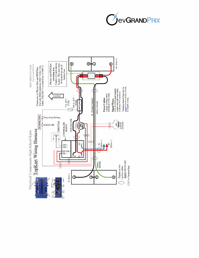
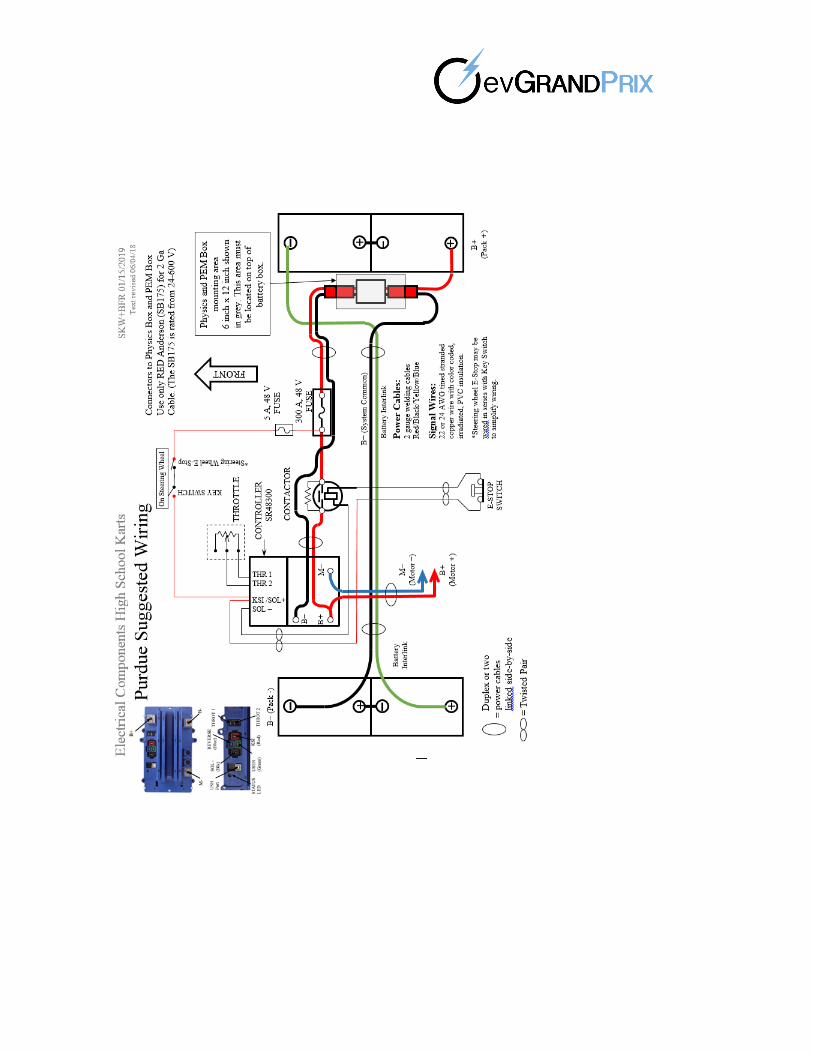
2.6.11 Emergency Switches – An emergency stop circuit must be
employed on the vehicle. The circuit will consist of a kill switch
located on the steering wheel and a mushroom style emergency stop
switch located on the rear of the vehicle in a location which is easily
recognizable, labeled, and accessible to emergency personnel. The kill
switch and the emergency stop switch will be wired in series with a
main contactor coil circuit. The contactor and power circuit must have
a short circuit current rating that exceeds the maximum peak current
draw of the vehicle. The circuit will consist of an appropriately sized
contactor (also known as solenoid relay) that will be connected in the
main positive power cable between the battery and any motor
controller. An indicator light must be included to signal when the
main contractor is closed. The light must be placed near the
emergency stop switch and must be visible to track personnel. See
Appendix G for an example.
2.6.12 Power Limit – The traction drive power system must not
exceed 14kW peak (18. 76hp peak) at any time during the race.
Power shall be defined as the instantaneous voltage multiplied by
the instantaneous current delivered by the battery. The system may
use any combination of battery instantaneous voltage and
instantaneous current, as long as this value does not exceed 14kW.
The voltage used for this calculation is not the battery pack nominal
voltage but the actual voltage, so teams must be aware of any over
voltage present in their packs when setting control limits. See
Appendix H1 for specifications.
2.6.13 Power and Energy Limit Enforcement – The power and energy limits (14kW and 4,320 watt hour respectively) will be enforced by the race officials using an Energy Power Monitor (EPM) installed by the teams with the supervision of the race officials before the race.
8.
2.6.14 The race vehicles must pass technical inspection prior to installation of the EPM. Teams will prewire and prepare a mount on their vehicle as specified in Appendix H and must make wiring schematics available to the race officials before the measurement system can be installed. If a team is found to exceed the maximum power usage during the race, they may be removed from the event, or other penalties may be applied. The vehicle is subject to re-‐‐ inspection at any time. See Appendix H1 for specifications.
2.6.15 Motor Specifications – Motors will be rated by the manufacturer to
handle the expected power load over the duration of the race. The peak power available to the motor drive system will not exceed 14kW. There is no limit on motor RPM, but teams must be aware of the manufacturer’s limitations for their motor. Motors will be limited to a maximum of 18.8 horsepower peak equivalent (14 kW) with respect to the voltage/current configuration of the kart. No single motor on a kart can weigh more than 50 pounds. No water-‐‐ cooled motors will be allowed.
2.6.16 Kart Speed – Kart shall not exceed a maximum speed of 55 mph and karts will be checked during practice and races to ensure compliance.
2.7 Control Systems
2.7.1 Throttle – Race vehicles shall be equipped with a foot-‐‐operated throttle potentiometer with two return springs, which will return the potentiometer to produce zero speed signals when the pedal is released. One spring must be located between the throttle pedal and the vehicle frame. A throttle return spring must also be located on the potentiometer throttle box to assure the potentiometer returns to zero signal when the pedal is released or in case a throttle cable is broken to prevent undesired actions.
2.7.2 Controllers – Any type of power controller is allowed.
Controller must be appropriately matched to the motor in order to
stay within the power limit and teams must follow all manufacturer
requirements related to the operation of the controller. The forward
power command to the motor must return to zero when the driver
releases the accelerator pedal. There are no restrictions to energy
management throttle control. Computers on or off the vehicle are
permitted, however; remote control of a vehicle is not permitted.
Karts with the ability for reverse will not be allowed.
2.7.3 Data Acquisition – Computers on or off the vehicle are legal for data acquisition purposes.
2.7.4 Remote Control – Remote control of a vehicle is prohibited.
No control signal can be transmitted back to the race vehicle for “on
the fly” adjustments.
2.8 Battery Charging
2.8.1 Chargers – Battery charging and equipment is the
responsibility of the race teams. Chargers with open components
9.

2.8.2 and circuits or damage will not be allowed. Charging of
batteries either on or off the vehicle will not be permitted in the pit
or on or near the track area. A specific battery charging area may be
provided where charging equipment can be set up and operated.
Backup type generators are not permitted to be operated during
race events.
Rules standards and procedures for the use of charging equipment and procedures will be provided in a separate charging equipment specifications document issued by officials.
2.8.3 Battery Management – All karts MUST utilize a battery
management system to prevent overcharging/discharging, and
overheating of the batteries, which can result in damage to the
battery cells and create a safety hazard.
2.9 General Vehicle Safety
Brakes – All race vehicles shall be equipped with pedal operated
Hydraulic brakes operating in such a manner as to stop both rear wheels equally. Brake linkages must have at least two (2) inches clearance off the ground. A cotter pin must be placed through the pivot pin, which connects the brake linkage lever to the master cylinder. Brake discs must be at least 1/8” thick. Brakes must be able to lock both rear wheels at maximum s p e e d . Regenerative braking does not have to be brake p eda l actuated.
2.9.1.1 Mechanical Driveline Guards (Chain Guard) – Open mechanical
drivelines including chain, belt, or gears must be guarded to reduce the possibility of personal injury and contact with the racing surface. Totally encased drives are exempt from this section.
2.9.1.2 Sprockets and sheaves mounted on the rear axle drive components must include a blank sprocket guard. The blank sprocket guard must be at least 1/4” larger in diameter than that of the axle sprocket or sheave being used. The bottom of the blank sprocket must maintain at least a one inch clearance above the racing surface at all times (measured with the race vehicle fully loaded). If tire wear or other circumstance create a condition where the guard, sprocket or sheave contacts the racing surface the race vehicle will be black flagged to the pits for corrections.
2.9.1.3 All open mechanical components will be guarded by a metal guard to prevent whipping if chain or belt breaks, prevent incidental contact with moving parts, and to prevent injury from rotating parts and pinch points. The guard will be securely mounted.
10
2.9.2 Steering C o n t r o l – The steering control shall be a direct acting mechanical system of suitable design for the maximum safety and prevention of over center lock. The steering shaft shall be either a minimum diameter of 5/8” solid rod or 19mm tubular steel. The steering wheel hub may be attached to solid shaft by.
2.9.3 taper and key. Solid or tubular shaft hub connections may be made using a quality TIG weld made to the non-‐‐stressed side (upper or steering wheel side) of the hub. A through bolt of at least .3125 inch diameter may be used on tubular shaft provided that there will is no play evident between the hub and shaft during inspection.
All steering assembly fasteners shall be castellated and cotter pinned. All steering assembly fasteners shall be of class 5 or better and a minimum of 3/8 inch in diameter. All rod ends shall be protected from collision. Nylon lock nuts are not permitted in the steering a s s e m b l y .
2.9.4 Steering Wheel – The steering wheel shall be of a circular or enclosed wing design. No post or handlebar steering wheels are al-‐‐ lowed. The steering wheel shall be attached to the hub by at least three cotter pin bolts with cotter pinned nuts or by bolts with safety wired heads where a threaded hub is used. Any sharp protrusions shall be covered. All nuts and bolts must be available for inspection.
2.9.5 Front Spindle and Rear Axle – The front spindle and rear axle shall not extend beyond the wheel widths. The rear axle shall be 1” minimum solid steel in diameter for cadet karts; all others must use a 40 mm or 50 mm tubular axle. Rear axles must be made of steel.
2.9.6 Seat and Floor Pan – The floor pan must fill the space inside of frame extending from the front frame member to the seat and made of material that meets specification
2.9.6.1 Seats may be made of resin impregnated fiberglass fabric, carbon fiber, or molded plastic. Fiberglass seat must be in good condition with no cracks or holes and be fastened to metallic seat sup-‐‐ ports using fender type washers and spacer grommets. No holes large enough for any part of the driver’s body to inadvertently pass through shall be permitted. The seatback must not exceed a 135-‐‐ degree angle from the floor pan. Seat bottom must be higher than the lower edge of frame tubing.
2.10 Vehicle Identification
2.10.1 Numbers – Kart numbers will be assigned by the Director of Competition on a first come, first served basis with the exception of #1, which is reserved for the previous year’s winner.
2.10.1.1 Only numbers 2-‐‐99 will be assigned to teams.
11.

2.10.1.2 Numbers will be assigned upon the completion of technical inspection, in the order in which teams pass inspection.
2.10.1.3 One number panel must be attached to the front of the kart, either to the roll cage, or nose fairing. A number panel must also be attached to either side of the kart, secured to the roll cage.
2.10.1.4 Only Mylar stick-on numbers will be allowed. No taped numbers are allowed.
2.10.1.5 All number panels shall be made of substantial material (not cardboard) and all edges shall be rolled, folded under, or protected with rubber or comparable material edging for maximum safety.
2.10.2 School Affiliation – It is recommended that a decal displaying school affiliation be placed on the side pods of the kart.
2.10.3 Series Sponsor – A 4” x 4” area on the front panel of the
race vehicle will be reserved for a series sponsor decal. Series
sponsor decals must be displayed at all events during the season.
2.10.4 Race Sponsor(s) – A 4” x 4” area on each side panel of the
race vehicle will be reserved for race sponsors decals. These must be
displayed at all times the event is running.
2.10.5 Team Sponsor(s) – The EvGrand Prix encourages the recruitment of commercial sponsors (marketing partners) for individual team entries. Teams must clear their sponsors through Danny White and insure compliance with their affiliated school guidelines before entering into any agreement. Any information given to before recruiting a sponsor will be held in confidence. No team may be sponsored by any organization or business associated with alcohol or tobacco, or things of a sexual or denigrating nature. This includes bars, where the bar is not set apart (separate) from a family area. Officials have final say on any discrepancies with the rule. Advertising of sponsors on the racing vehicle shall be limited to signage located on front, rear and side panels and crushable of the race vehicle. The advertising in the front shall be kept at least 3 inches from each side of the front number panel.
3.0 TEAM EQUIPMENT
3.0 Required Safety Equipment – All team required safety equipment is the responsibility of the individual race team and shall be brought to technical inspection and shall also be available for re-inspection at any time.
3.1. Appearance – It is essential that every effort be made to present
the most professional racing appearance possible. To this end, certain minimum requirements shall be imposed on all competitors.
12.
3.2 Helmet – The driver’s helmet must be one of the following ratings: Snell SA 2005‐2015, Snell K 2005‐2015, Snell M 2005‐2015, CMS 2007 Youth Helmet, CMR 2007 Youth Helmet, SFI 24.1/2010, SFI 31.1/2010, SFI 41.1/2010, BSI A type and A/FR types.
3.3 Drivers Protective Clothing
3.3.1 Driver’s suit must be manufactured for racing. Suit must be constructed of heavy weight, abrasion resistant nylon. Driving suits must meet SFI rating 3.2.
3.3.1.1 The driver’s suit must cover the ankles and wrists while seated in the kart. Exposed skin will result in a black flag penalty.
3.3.2 To prevent or minimize abrasions, all drivers shall wear gloves of Kevlar, leather or vinyl material.
3.3.3 The driver shall wear approved neck brace, socks covering the ankles, a rib protection vest and full coverage sturdy shoes, boots or racing shoes.
3.4 Crew Clothing – At all times in the pit and paddock area all crew members must wear shirts, closed toe shoes, full length pants, and safety glasses. No sweat pants, jeans with holes, polyester or plastic clothing, or shorts will be allowed. Sponsor and school logos are allowed. All graphics on clothing must be in good taste. It is encouraged that each team have a uniform look for visual impact and professionalism.
3.5 Fire Extinguishers – Each team will provide at least one CO2 type Underwriters Laboratory approved fire extinguisher with a minimum capacity of 2 1/2 pounds. This must be brought to technical inspection, practice, qualifications, and the race. The fire extinguisher must have been inspected within the last twelve months, tagged, and sealed are required. All fire extinguishers within the pit area must display the inspection sticker provided at the technical inspection. Fire extinguishers must be on hand when the race vehicle is being energized
13.
DISCLAIMER Any use of an Ev Grand Prix go kart, outside of any specified Ev Grand Prix Fall or Spring karting program, is at the sole risk, responsibility, and liability of the go-kart owner. Purdue University and its Ev Grand Prix partners are not liable for any incident or injury resulting from the use of any Ev Grand Prix go-kart. Future Event Director / Race Director Trainings will be made available for teams outside a 200 mile radius of Indianapolis. That is stage one for remote events. Target, 2021 EV Grand Prix is a NFPA 610 compliant series as required by our host IMS, all series events must be overseen by someone at the Technician – Incident Command Level. For remote events and races, there are specific guidelines that must be met. Including but not limited to those with local emergency response agencies and others. There are several other levels of certifications required for many different event Directors and Personnel. See the 2019/2020 rule book for further on this subject. Safety is our first priority in this student based series. We do not foresee any regional events of any type in the Midwest unless approved and overseen by WKA / EV Grand Prix Safety Directors. All special event requests have to be approved by:
Danny White, International Program Director, EV Grand Prix – Purdue University
Bill McLaughlin – World Karting Association (WKA) Competition Board
14.
3.0 APPENDICES
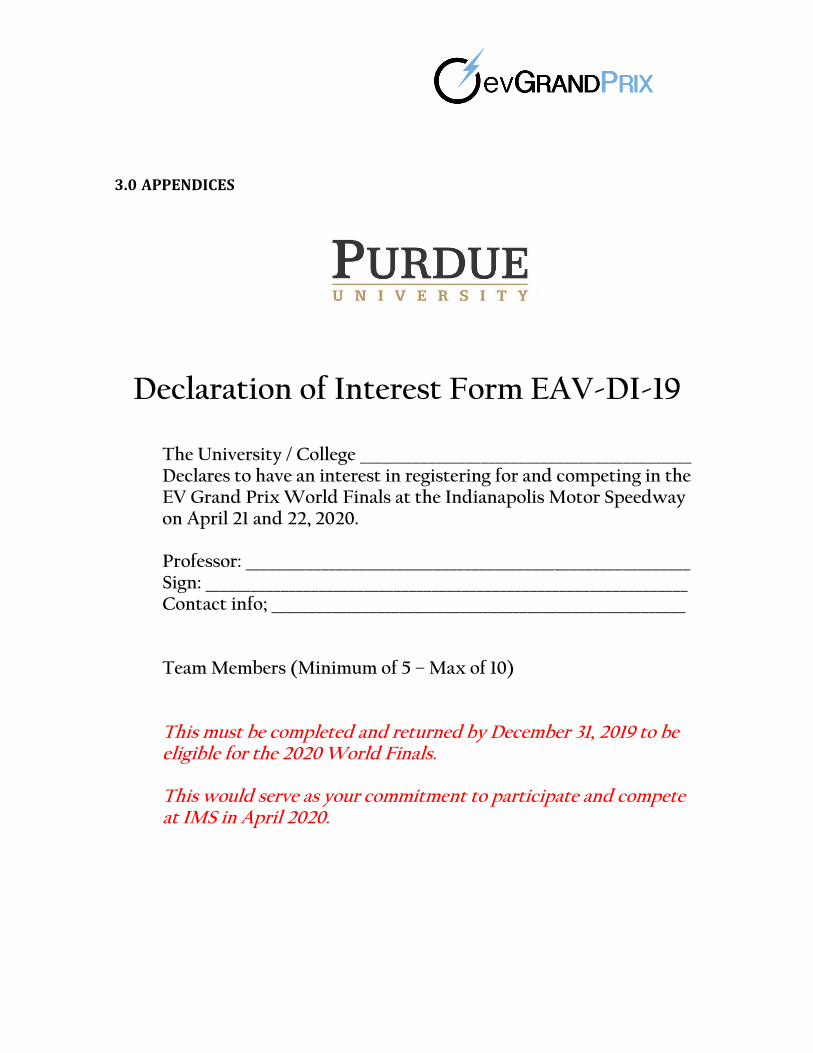
Declaration of Interest Form EAV-DI-19
The University / College ____________________________________________ Declares to have an interest in registering for and competing in the EV Grand Prix World Finals at the Indianapolis Motor Speedway on April 21 and 22, 2020. Professor: ___________________________________________________________ Sign: ________________________________________________________________ Contact info; _______________________________________________________
Team Members (Minimum of 5 – Max of 10) This must be completed and returned by December 31, 2019 to be eligible for the 2020 World Finals. This would serve as your commitment to participate and compete at IMS in April 2020.
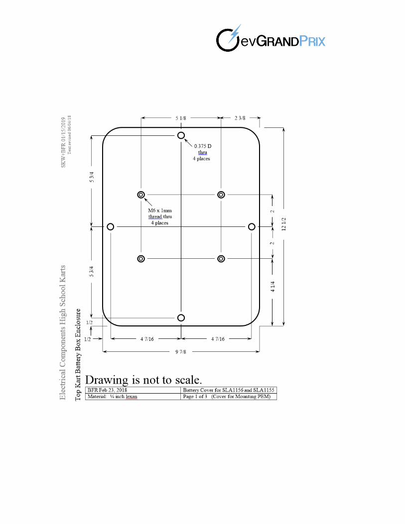
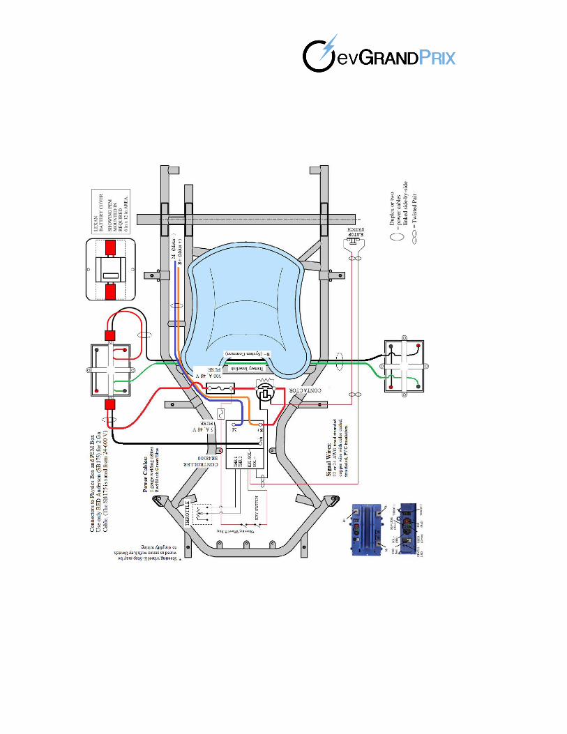
Appendix A 20.1 PEM Specs
Traction drive power and energy will be limited to the maximums outlined in specification 14.4. An electronic instrument will be mounted on the vehicle to indicate and measure, at a minimum, instantaneous power from the battery and the accumulated energy used from the battery. This instrument is referred to as the Power and Energy Monitor (PEM).
The purpose of the PEM is to accurately measure and record the power and energy delivered by the battery of each racer during event competitions. Electric from the battery power, expressed in watts, is calculated using the instantaneous voltage multiplied by the instantaneous current. Energy consumed from the battery, expressed in watt-‐‐hours, is calculated by integrating the power over time. During a racing event, a penalty will be assessed to racers that exceed a defined peak power limit. At the conclusion of the event, the total energy consumed by the racer will be noted by a race official.
The objective of the PEM is to encourage electric drive innovation by removing restrictions on specified configurations and components, such as motors and controllers, in favor of a maximum performance envelope. This open formula fosters team competition and design variety while preserving tight wheel-‐‐to-‐‐wheel racing throughout the field which is vital to spectator enthusiasm.
-‐‐ The PEM hardware module will be provided to teams by race officials before a competition
-‐‐ Teams are responsible for mounting the PEM using only the approved bracket and wire harness
-‐‐ Proper PEM operation will be verified by officials after technical inspection and during open track practice
-‐‐ It is the responsibility of teams to report any issues they have with the PEM to an official a8 soon as they become aware of such issue

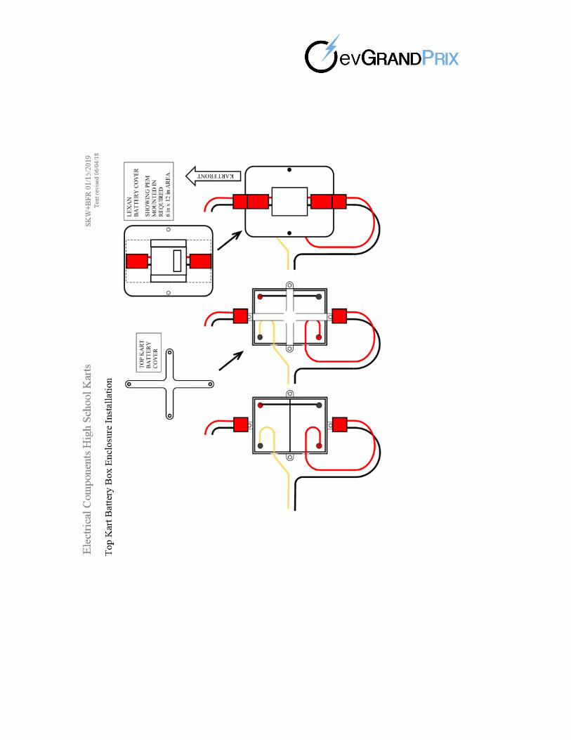
PEM Vehicle Integration Requirements
On each kart, the following mounting space will be required:
-‐‐ A flat unobstructed and non-conductive area of 12 inches by 6 inches
-‐‐ This area should be on top of the battery pack
-‐‐ On one end of the PEM
o + is the maximum battery voltage
o – is the minimum battery voltage
-‐‐ On the other end of the PEM
o + goes to the positive-‐‐end of the drive system (the fuse is first in this system)
o – goes to the negative end of the drive system (B-‐‐ on the controller)
** See wiring diagram for details
** The connectors to the vehicle’s drive system and the battery MUST BE the RED ANDERSON SB175 POWERPOLE CONNECTOR (175 amp).
Please note that OTHER COLORS WILL NOT WORK as they are notched differently.
See www.evgrandprix.org/parts for details and suppliers.