20304726 power electronics chapter 1
TRANSCRIPT

8/8/2019 20304726 Power Electronics Chapter 1
http://slidepdf.com/reader/full/20304726-power-electronics-chapter-1 1/51
Overview to
Power Electronics
Mohd Shawal Bin Jadin
Ext : 2321A01-2074

8/8/2019 20304726 Power Electronics Chapter 1
http://slidepdf.com/reader/full/20304726-power-electronics-chapter-1 2/51
Learning OutcomesLearning Outcomes At the end of the lecture, student
should be able to:
± Identify the function of electronics
switches, hence to select a proper
switching for certain applications.
± Outline the principles of energy recovery
and also to calculate the power for non-
sinusoidal periodic waveform

8/8/2019 20304726 Power Electronics Chapter 1
http://slidepdf.com/reader/full/20304726-power-electronics-chapter-1 3/51
Definition of PowerDefinition of Power
ElectronicsElectronics
Multidisciplinary Nature of Multidisciplinary Nature of
the Fieldthe Field Block Diagrams of PowerBlock Diagrams of Power
Electronic SystemsElectronic Systems
The Need for PowerThe Need for Power
ElectronicsElectronics
Future TrendsFuture Trends Types of Power ConversionTypes of Power Conversion
Electronic SwitchElectronic Switch
Switch SelectionSwitch Selection
Energy RecoveryEnergy Recovery
Chapter 1Chapter 1Power Electronic
"Power" Circuit
Feedback
"Control Circuit"
Load1
Load2
Loadn
ElectricalInputs
"Sources"
Electrical or Mechanical
Output "Loads"
x1
x2
xm
y1
y2
yn
f 1 f 2 f k
Power
Processing
circuit
(Ploss
)
(input)
Source Side
(output)
Load Side
Load

8/8/2019 20304726 Power Electronics Chapter 1
http://slidepdf.com/reader/full/20304726-power-electronics-chapter-1 4/51
What is Power Electronics? Generally:
± Electronics: Solid State Electronics Devices and their
Driving Circuits. ± Power: Static and Dynamic Requirements for Generation,
Conversion and Transmission of Power.
± Control: The Steady State and Dynamic Stability of the
Closed Loop system.
POWER ELECTRONICS may be defined as the
application of Solid State Electronics for the
Control and conversion of Power.

8/8/2019 20304726 Power Electronics Chapter 1
http://slidepdf.com/reader/full/20304726-power-electronics-chapter-1 5/51
Definition of Power ElectronicsDefinition of Power Electronics DEFINITION:
To convert, i.e to process and control the flow of
electric power by supplying voltages and currentsin a form that is optimally suited for user loads.

8/8/2019 20304726 Power Electronics Chapter 1
http://slidepdf.com/reader/full/20304726-power-electronics-chapter-1 6/51
Power Electronics (PE) SystemsPower Electronics (PE) Systems To convert electrical energy from one form to
another, i.e. from the source to load with:
highest efficiency,
highest availability
highest reliability
lowest cost,
smallest size
least weight

8/8/2019 20304726 Power Electronics Chapter 1
http://slidepdf.com/reader/full/20304726-power-electronics-chapter-1 7/51
Detailed Block Diagram of PowerDetailed Block Diagram of Power
Electronics SystemElectronics System
Filter
&
Recti y
ircuit oad
Filter
&
Recti y
ontrolircuitechanical Variable
Feedback
lectrical Variable
Feedback
Input
Form oelectrical
energy
lectrical
echanical
re-stageo er proc. stage ost stage
utput
Form o elec. or
mechan. energy
i t c h
D r
i v
e s
rocess eedback
signals and decide
on control
ould generate
undesirable
ave orms
ostly ac line
voltage (single
or three phase)
ostly
unregulate
d dc
voltage
Inter ace bet een
control and po er
circuits

8/8/2019 20304726 Power Electronics Chapter 1
http://slidepdf.com/reader/full/20304726-power-electronics-chapter-1 8/51
Applications Static applications
± involves non-rotating or moving mechanical
components.
± Examples:
DC Power supply
Un-interruptible power supply, Power generation and
transmission
(HVDC), Electroplating, Welding, Heating,
Cooling, Electronic ballast

8/8/2019 20304726 Power Electronics Chapter 1
http://slidepdf.com/reader/full/20304726-power-electronics-chapter-1 9/51
Applications Drive applications
± intimately contains moving or rotating
components such as motors.
± Examples:
Electric trains, Electric vehicles, Air-conditioning
System, Pumps, Compressor,
Conveyer Belt (Factory automation).

8/8/2019 20304726 Power Electronics Chapter 1
http://slidepdf.com/reader/full/20304726-power-electronics-chapter-1 10/51
Application examples Static Application: DC Power Supply

8/8/2019 20304726 Power Electronics Chapter 1
http://slidepdf.com/reader/full/20304726-power-electronics-chapter-1 11/51
Application examples Drive Application: Air-Conditioning System

8/8/2019 20304726 Power Electronics Chapter 1
http://slidepdf.com/reader/full/20304726-power-electronics-chapter-1 12/51
Other ApplicationsOther Applications
Heating, cooling, CFLHeating, cooling, CFLElectroplating, WeldingElectroplating, Welding
Photovoltaic Systems.Photovoltaic Systems.eV (fuel cell, Solar)eV (fuel cell, Solar)
WindWind--electric systems.electric systems.

8/8/2019 20304726 Power Electronics Chapter 1
http://slidepdf.com/reader/full/20304726-power-electronics-chapter-1 13/51
Conversion concept: exampleConversion concept: example11
Supply from TNB: 50Hz, 240V RMS (340V peak).Customer need DC voltage for welding purpose, say.
TNB i - v ly
iv z DCm !
Av v l
W im l h lf-
v ifi . A fix DC
v l i b i .Thi i im l E y m.
1 El i , M D Z i l l m, UTM

8/8/2019 20304726 Power Electronics Chapter 1
http://slidepdf.com/reader/full/20304726-power-electronics-chapter-1 14/51
Conversion concept: example (Cont)Conversion concept: example (Cont)11
How about if customer wants variable DC voltage?
± More complex circuit using SCR is required.
By lli h fi i l , , h DC v l
f v i b v i .
1 El i , M D Z i l l m, UTM
Av V l

8/8/2019 20304726 Power Electronics Chapter 1
http://slidepdf.com/reader/full/20304726-power-electronics-chapter-1 15/51
Advantages of Advantages of Power ElectronicsPower Electronics
High energy conversion efficiencyHigh energy conversion efficiency
± Instead of using 50/60Hz motor-generator
Higher Reliability and cost effective
± Less maintenance, longer lifetime, light and small size, fast recovery time, unlimitedrange of conversion
Environmentally clean and safeEnvironmentally clean and safe
± produce no hazardous waste products
± Burning of fossil fuel emits gases such as C,0,, CO (oil burning), S02, NOx (coalburning) etc. Creates global warming (green house effect), acid raill and urbanpollution h-oll)
Q uite operationQ uite operation
± has no moving parts, suitable for residential, hotels etc
reduce dependence on fossil fuel (coal, natural gas, oil) and nuclear power resourcereduce dependence on fossil fuel (coal, natural gas, oil) and nuclear power resource(uranium).(uranium). ± Effort to tap renewable energy resources such as solar, wind, fuel-cell etc. need to be increased.
Special effort is needed to reduce pollution in cities by enforcing the use of electricvehicle.

8/8/2019 20304726 Power Electronics Chapter 1
http://slidepdf.com/reader/full/20304726-power-electronics-chapter-1 16/51
PE growth
PE growth
PE rapid growth due to:PE rapid growth due to:
± Advances in power (semiconductor) switches
Advances in microelectronics(DSP, VLSI, microprocessor /
microcontroller, ASIC)
New ideas in control algorithms
Demand for new applications

8/8/2019 20304726 Power Electronics Chapter 1
http://slidepdf.com/reader/full/20304726-power-electronics-chapter-1 17/51
PE is an interdisciplinary field: ± ± Digital/analogue electronicsDigital/analogue electronics
± ± Power and energyPower and energy
± ± MicroelectronicsMicroelectronics
± ± Control systemControl system
± ± Computer, simulation and softwareComputer, simulation and software
± ± SolidSolid--state physics and devicesstate physics and devices
± ± PackagingPackaging
± ± Heat transferHeat transfer

8/8/2019 20304726 Power Electronics Chapter 1
http://slidepdf.com/reader/full/20304726-power-electronics-chapter-1 18/51
Power Electronics ConvertersPower Electronics Converters
AC to DC: RECTIFIERAC to DC: RECTIFIER
DC to DC: CHOPPERDC to DC: CHOPPER
DC toA
C: INVERTERDC toA
C: INVERTER
AC to AC: CYCLOCONVERTERAC to AC: CYCLOCONVERTER

8/8/2019 20304726 Power Electronics Chapter 1
http://slidepdf.com/reader/full/20304726-power-electronics-chapter-1 19/51
Power semiconductor devicesPower semiconductor devices
(Power switches)(Power switches)
C b i i h :
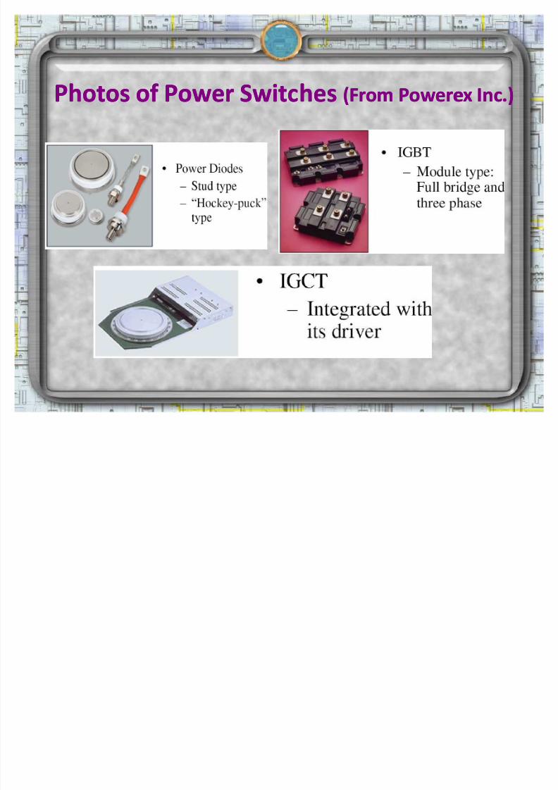
± Uncontrolled: Diode
± Semi-controlled: Thyristor (SCR)
± Fully controlled: Power transistors e.g.
BJT,MO FET, IGBT, GTO, IGCT
8/8/2019 20304726 Power Electronics Chapter 1
http://slidepdf.com/reader/full/20304726-power-electronics-chapter-1 20/51
Photos of Power SwitchesPhotos of Power Switches (From(From PowerexPowerex Inc.)Inc.)

8/8/2019 20304726 Power Electronics Chapter 1
http://slidepdf.com/reader/full/20304726-power-electronics-chapter-1 21/51
Power Electronics ConvertersPower Electronics Converters
AC to DC: RECTIFIERAC to DC: RECTIFIER
DC to DC: CHOPPERDC to DC: CHOPPER
DC toA
C: INVERTERDC toA
C: INVERTER
AC to AC: CYCLOCONVERTERAC to AC: CYCLOCONVERTER

8/8/2019 20304726 Power Electronics Chapter 1
http://slidepdf.com/reader/full/20304726-power-electronics-chapter-1 22/51
The Need For Switching In Power Electronic CircuitsThe Need For Switching In Power Electronic Circuits
The need to use semiconductor switching devices inpower electronic circuits is based on their ability tocontrol and manipulate very large amounts of power from
the input to the output with relatively very low powerdissipation in the switching device.
Implication of low efficiency:
1. The cost of energy increasescost of energy increases due to increasedconsumption.
2. Additional design complications might be imposed,especially regarding the design of device heat sinksdesign of device heat sinks

8/8/2019 20304726 Power Electronics Chapter 1
http://slidepdf.com/reader/full/20304726-power-electronics-chapter-1 23/51
ExampleExampleInvestigate the efficiency of four different power electronic
circuits whose function is to take power from a 2424 VV dcdc sourcesourceandand deliverdeliver aa 1212 VV dcdc outputoutput toto aa 66;; resistiveresistive loadload. In otherwords, the task of these circuits is to serve as dc transformerswith a ratio of 2 : 1. The four circuits are shown in Fig. 1 (a), (b),(c), and (d) representing a voltagevoltage dividerdivider circuit,circuit, zenerzener regulatorregulator((assumeassume IIZZ isis 1010%% of of loadload current)current),, transistortransistor linearlinear regulator,regulator, andandswitchingswitching circuit,circuit, respectivelyrespectively. [Hint: For circuit (d), Vo=Vin*D]

8/8/2019 20304726 Power Electronics Chapter 1
http://slidepdf.com/reader/full/20304726-power-electronics-chapter-1 24/51
(e) Zener diode i-v switching characteristics. (f) Switching waveforms for circuit
Example (Cont)Example (Cont)

8/8/2019 20304726 Power Electronics Chapter 1
http://slidepdf.com/reader/full/20304726-power-electronics-chapter-1 25/51
Example (Cont)Example (Cont)
Cicuit (a) : VoltageDivider dc RegulatorCicuit (a) : VoltageDivider dc Regulator Since Vin=24V and RL=6; and desired Vo=12V.
Hence, R =R = RRLL=6=6;;.
Thus,%50%
66
6%
%%
!
!
!
!!
R R
R
P
P
P
P
L
L
in
L
in
out L
CicuitCicuit (b) :(b) : Zener Zener dc Regulator dc Regulator
i i V =12V, h h bl ki v l f z i , VZ
= 12V.
i , R =6;. Th I =2A. A m h , I A m h , IZZ = 0.2A= 0.2A
10% f l10% f l
Th ,
%5.45%8
.52
24%
24122
8.52242.2
2.22.02
!!!
!v!
!v!
!!
!
in
out
out
in
z
T
W
W
A
I I I
L

8/8/2019 20304726 Power Electronics Chapter 1
http://slidepdf.com/reader/full/20304726-power-electronics-chapter-1 26/51
Example (Cont)Example (Cont)
CicuitCicuit (c) : Transistor dc Regulator(c) : Transistor dc Regulator
For Vo=12V, it is clear that VCE must be around 12V.
Hence, the control circuit must provide base current, IB to put
transistor in active mode with VCE=12V. For given Vo=12V andRL=6;, thus IILL=2A=2A.
Thus, IICC = 2A= 2A since IB too small in such that to turn on transistor.
%50%48
24%
24212
48)24(2
!!!@
!v}}
!
!!!
in
out
C CE
B BE C CE diss
cinin
P
P
W I V
I V I V P
W I V P
L

8/8/2019 20304726 Power Electronics Chapter 1
http://slidepdf.com/reader/full/20304726-power-electronics-chapter-1 27/51
Example (Cont)Example (Cont)
CicuitCicuit (d) : Switching dc Regulator (d) : Switching dc Regulator A m h i h i i l i i lly ff.
F m fi f , V i iv by
%100%48
48%,
),(
48242,24
!!!!
!v!v!!
in
out inout
in Linin
P
P P P
ideal assume switching to Due
W V I P V V Since
L
´ !!
DT
inin
s
aveo
s
DV dt V T V 0
,
1
F V , v =12V, h D=0.5D=0.5 VV , v, v =24 x 0.5 =12V=24 x 0.5 =12V

8/8/2019 20304726 Power Electronics Chapter 1
http://slidepdf.com/reader/full/20304726-power-electronics-chapter-1 28/51
Ideal Switch
ingCh
aracteristicsIdeal Switch
ingCh
aracteristics1. No limit on the amount of current that the device can
carry when in the conduction state (on-state)
2. No limit on the amount of device voltage (known as
blocking voltage) when the device is in the non-
conduction state (off-state)
3. Zero on-state voltage drop when in the conduction
state
4. Zero leakage current when in the nonconduction
state
5. No limit on the operating speed of the device when it
changes state, i.e., zero rise and fall times

8/8/2019 20304726 Power Electronics Chapter 1
http://slidepdf.com/reader/full/20304726-power-electronics-chapter-1 29/51
Ideal Switch
ingCh
aracteristicsIdeal Switch
ingCh
aracteristics
Power lossPower loss

8/8/2019 20304726 Power Electronics Chapter 1
http://slidepdf.com/reader/full/20304726-power-electronics-chapter-1 30/51
Th
e Practical Switch
Th
e Practical Switch
The practical switch has the following switchingand conduction characteristics:
1.1. Limited powerLimited power--handling capabilitieshandling capabilities
2.2. Limited switching speedLimited switching speed
3.3. TheThe existence of forward voltage drop in the onexistence of forward voltage drop in the onstate, and reverse current flow (leakage) in thestate, and reverse current flow (leakage) in theoff stateoff state
4. Because of characteristics 2 and 3, the practicalswitch experiences power losses in the on andswitch experiences power losses in the on andoff states (known as conduction loss) and duringoff states (known as conduction loss) and duringswitching transitions (known as switching loss)switching transitions (known as switching loss)

8/8/2019 20304726 Power Electronics Chapter 1
http://slidepdf.com/reader/full/20304726-power-electronics-chapter-1 31/51
PowerD
iodesPowerD
iodes
When diode is forward biased, it conducts current with asmall forward voltage (V f ) across it (0.2-3V)
When reversed (or blocking state), a negligibly small leakagecurrent (uA to mA) flows until the reverse breakdownoccurs. Diode should not be operated at reverse voltagegreater than V r . Thus, higher voltage blocking is needed.Thus, higher voltage blocking is needed.

8/8/2019 20304726 Power Electronics Chapter 1
http://slidepdf.com/reader/full/20304726-power-electronics-chapter-1 32/51
PowerPower Diode (ReverseDiode (Reverse Recovery)Recovery)
When a diode is switched quickly from forward toreverse bias, itit continuescontinues toto conductconduct due to themi nor i ty carr i ers which remains in the p-n
junction.
The minority carriers require finite time, i.e, t rr (reverse recovery time) to recombine withopposite charge and neutralize.
Effects of reverse recovery are increase inswitching losses, increase in voltage rating, over-voltage (spikes) in inductive loads

8/8/2019 20304726 Power Electronics Chapter 1
http://slidepdf.com/reader/full/20304726-power-electronics-chapter-1 33/51
PowerPower Diode (ReverseDiode (Reverse Recovery)Recovery)

8/8/2019 20304726 Power Electronics Chapter 1
http://slidepdf.com/reader/full/20304726-power-electronics-chapter-1 34/51
Types of Power DiodesTypes of Power Diodes
Line frequency (general purposeLine frequency (general purpose) :) :
on state voltage very low(below 1V)
large t rr (about 25us)
very high current (up to 5kA)and voltage (5kV) ratings
Used in line-frequency(50/60Hz)
applications such as rectifiers
Fast recoveryFast recovery ver y low trr (<1 s). Power levels at several
h red volts and several
h ndred am s Nor mally used in hi h f requency circuits
SchottkySchottky ver y low f orward voltage drop (typical 0.3V) limited blocking voltage (50-100V) Used in low voltage, high current application such as switched mode power
supplies.

8/8/2019 20304726 Power Electronics Chapter 1
http://slidepdf.com/reader/full/20304726-power-electronics-chapter-1 35/51
Thyristor basedThyristor based Thyristor refers to the family of power semiconductor
devices made of threethree pnpn junctions junctions (fourfour layerslayers of of pnpnpnpn)that cancan bebe latchedlatched intointo thethe onon statestate throughthrough anan externalexternalgategate signalsignal that causes a regeneration mechanism in thedevice.
Thyristor family currently used in power electroniccircuits:
± ± TheThe siliconsilicon--controlledcontrolled rectifierrectifier (SCR),(SCR),
± ± gategate turnturn--off off thyristorthyristor (GTO),(GTO), ± ± triodetriode acac switchswitch (triac),(triac),
± ± staticstatic inductioninduction transistortransistor (SIT),(SIT),
± ± staticstatic inductioninduction thyristorthyristor (SITH),(SITH),
± ± andand MOSMOS--controlledcontrolled thyristorthyristor (NICT)(NICT)..
8/8/2019 20304726 Power Electronics Chapter 1
http://slidepdf.com/reader/full/20304726-power-electronics-chapter-1 36/51
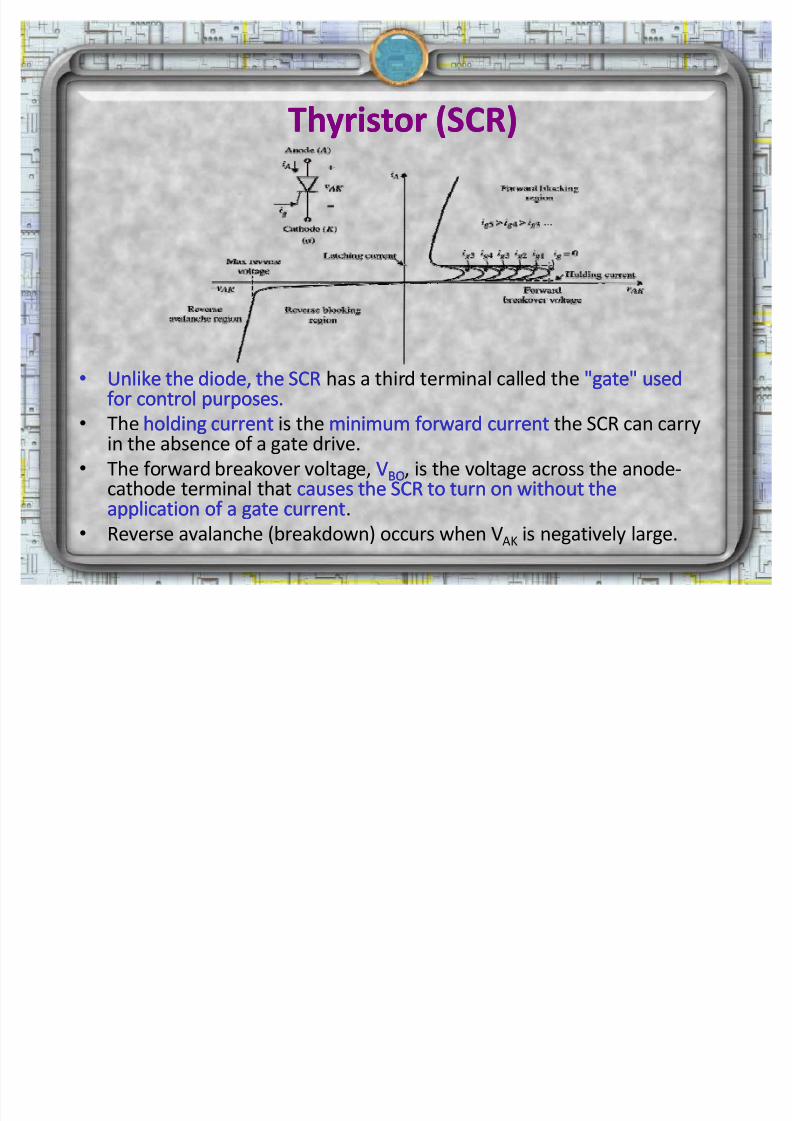
Thyristor (SCR)Thyristor (SCR)
Unlike the diode, the SCRUnlike the diode, the SCR has a third terminal called the "gate" used"gate" usedfor control purposes.for control purposes.
The holding currentholding current is the minimum forward currentminimum forward current the SCR can carryin the absence of a gate drive.
The forward breakover voltage, VVBOBO, is the voltage across the anode-cathode terminal that causes the SCR to turn on without thecauses the SCR to turn on without theapplication of a gate currentapplication of a gate current.
Reverse avalanche (breakdown) occurs when VAK is negatively large.

8/8/2019 20304726 Power Electronics Chapter 1
http://slidepdf.com/reader/full/20304726-power-electronics-chapter-1 37/51
Thyristor (SCR)Thyristor (SCR)
Thyristors can only be turned on with two conditions:
thethe devicedevice isis inin forwardforward blockingblocking statestate ((ii..ee V V ak ak isis positive)positive)
aa positivepositive gategate currentcurrent ((IIgg)) isis appliedapplied atat thethe gategate
Once conducting, the anode current is LATCHED (continuously flowing).
In reversereverse -- biasedbiased mode,mode, thethe SCRSCR behavesbehaves likelike aa diodediode.. It conducts a smallleakage current which is almost dependent of the voltage, but increases withtemperature.
When the peak reverse voltage is exceeded, avalancheavalanche breakdownbreakdown occursoccurs, andthe large current will flow.
In the forward biased mode, with no gate current present (i.e. in theuntriggered state), the device exhibits a leakage current.
If the forward breakover voltage (VBO) is exceeded, the SCR self-triggers intothe conducting state and the voltage collapses to the normal forward volt-drop,typically 1.5-3V. The presence of any gate current will reduce the forwardbreakover voltage.

8/8/2019 20304726 Power Electronics Chapter 1
http://slidepdf.com/reader/full/20304726-power-electronics-chapter-1 38/51
Thyristor ConductionThyristor Conduction
How to turn off thyristor ?

8/8/2019 20304726 Power Electronics Chapter 1
http://slidepdf.com/reader/full/20304726-power-electronics-chapter-1 39/51
Thyristor ConductionThyristor Conduction
Thyristor cannot be turned off by applying negativenegative
gategate currentcurrent. It can only be turned off if I A goes
negative (reverse)
ThisThis happenshappens whenwhen negativenegative portionportion of of thethe of of
sinesine--wavewave occursoccurs (natural commutation).
Another method of turning off is known as forcedcommutation,
TheThe anodeanode currentcurrent isis diverteddiverted toto anotheranother
circuitrycircuitry..

8/8/2019 20304726 Power Electronics Chapter 1
http://slidepdf.com/reader/full/20304726-power-electronics-chapter-1 40/51
ControllableControllable switches (powerswitches (power transistors)transistors)
Can be turned ONand OFF by relatively very small controlsignals.
Operated in SATURATION and CUTOFF modes onlySATURATION and CUTOFF modes only. No linear
region operation is allowed due to excessive power loss.
In general, power transistors do not operate in latched modepower transistors do not operate in latched mode.
T rad i t i onal dev i ces: Bipolar junction transistors (BJT), Metal oxideBipolar junction transistors (BJT), Metal oxidesilicon field effect transistor ( MOSFET), Insulated gate bipolarsilicon field effect transistor ( MOSFET), Insulated gate bipolartransistors (IGBT), Gate turntransistors (IGBT), Gate turn--off off thyristorsthyristors (GTO)(GTO)
E mergi ng (new) dev i ces: Gate controlled thyristors (GCT).

8/8/2019 20304726 Power Electronics Chapter 1
http://slidepdf.com/reader/full/20304726-power-electronics-chapter-1 41/51
Bipolar Junction Transistor (BJT)Bipolar Junction Transistor (BJT)
Ratings: Voltage: V V C E C E
<<10001000,, CurrentCurrent:: IIC C <<400400AA.. SwitchingSwitching
frequencyfrequency upup toto 55kHzkHz.. LowLow onon--statestate voltagevoltage:: V V C E (sat)C E (sat) :: 22--33VV..
Low current gain (). Need high base current to obtainreasonable I
C . (Current driven).(Current driven). Expensive and complexExpensive and complex
base drive circuit.base drive circuit.
Not popular in new productsNot popular in new products.

8/8/2019 20304726 Power Electronics Chapter 1
http://slidepdf.com/reader/full/20304726-power-electronics-chapter-1 42/51
BJT ConductionBJT Conduction
sat ¡
sat ¡
¢
sat I
!
The level of IB in the active region just bef ore saturation
must be
At saturation, the current IC is quite high and the voltage
VCE ver y low. The resistance across the ter minals
deter mined by
d c
sat c£
I I
F"
max
Saturation conditions andSaturation conditions and
the resulting ter minal resistancethe resulting ter minal resistance
Cutoff conditions andCutoff conditions and
the resulting ter minal resistancethe resulting ter minal resistance

8/8/2019 20304726 Power Electronics Chapter 1
http://slidepdf.com/reader/full/20304726-power-electronics-chapter-1 43/51
Metal Oxide SiliconMetal Oxide Silicon Field EffectField Effect Transistor (MOSFET)Transistor (MOSFET)
Ratings: VoltageVoltage V V DSDS
<500V, current<500V, current IIDSDS
<300A.<300A. (Voltage(Voltage
driven)driven)
Very fast device: >100KHz. For some low power devices (few
hundred watts) may go up to MHz range.

8/8/2019 20304726 Power Electronics Chapter 1
http://slidepdf.com/reader/full/20304726-power-electronics-chapter-1 44/51
MOSFET characteristicsMOSFET characteristics Turning on and off is very simpleTurning on and off is very simple. Only need to provide V
GS
=+15V to turn on and 0V to turn off. Gate drive circuit isGate drive circuit issimple.simple.
Basically low voltage device. High voltage device areBasically low voltage device. High voltage device areavailable up to 600V but with limited currentavailable up to 600V but with limited current. Can beparalleled quite easily for higher current capability.
Internal (dynamic) resistance between drain and sourceresistance between drain and sourceduring on state,during on state, RR
DS(ON)DS(ON) , , limits the power handling capabilitylimits the power handling capability
of MOSFETof MOSFET. High losses especially for high voltage device dueto R
DS(ON) .
Dominant in high frequency applicationhigh frequency application (>100kHz). Biggestapplication is in switchedapplication is in switched--mode power suppliesmode power supplies.

8/8/2019 20304726 Power Electronics Chapter 1
http://slidepdf.com/reader/full/20304726-power-electronics-chapter-1 45/51
Insulated GateInsulated Gate Bipolar TransistorBipolar Transistor (IGBT)(IGBT)
Combination of BJT and MOSFET characteristics.
Compromises include:
Gate behaviour similar to MOSFET - easy to turn on and off.
Low losses like BJT due to low on-state Collector-Emitter
voltage (2-3V).

8/8/2019 20304726 Power Electronics Chapter 1
http://slidepdf.com/reader/full/20304726-power-electronics-chapter-1 46/51
Ratings: Voltage: VCE<3.3kV, Current,: IC<1.2kA currentlyavailable. Work in under progress for 4.5kV/1.2kA device.Constant improvement in voltage and current ratings.
Good switching capability (up to 100KHz) for newer devices.
Typical application, IGBT is used at 20-50KHz.
For very high power devices and applications, frequency islimited to several KHz.
Very popular in new products; practically replacing BJT inmost new applications.
Snubberless operation is possible. Most new IGBTs do notrequire snubbers.
Insulated GateInsulated Gate Bipolar TransistorBipolar Transistor (IGBT)(IGBT)

8/8/2019 20304726 Power Electronics Chapter 1
http://slidepdf.com/reader/full/20304726-power-electronics-chapter-1 47/51
Gate turnGate turn--off off thyristorthyristor (GTO)(GTO)
Behave like normal thyristor, but can be turned off usingbut can be turned off using
gate signalgate signal
However turning off is difficultturning off is difficult. Need very large reverse
gate current (normally 1/5 of anode current)

8/8/2019 20304726 Power Electronics Chapter 1
http://slidepdf.com/reader/full/20304726-power-electronics-chapter-1 48/51
Ratings: Voltage:Voltage: V V ak ak <5kV; Current:<5kV; Current: IIaa<5kA.<5kA. Highest power ratingsswitch. Frequency<5KHz.
Gate drive design is very difficultGate drive design is very difficult. Need very large reverse gatecurrent to turn off. Often custom-tailored to specific application.
Currently getting very stiff competition from high power IGBTCurrently getting very stiff competition from high power IGBT. Thelatter has much simpler and cheaper drivers.
GTO normally requires snubbers. High power snubbers areexpensive.
In very high power region (>5kV, >5kA), development in gate-controlled thyristor (GCT) may effectively end the future of GTO
Gate turnGate turn--off off th
yristorth
yristor (GTO)(GTO)

8/8/2019 20304726 Power Electronics Chapter 1
http://slidepdf.com/reader/full/20304726-power-electronics-chapter-1 49/51
Switches comparisons (2000)Switches comparisons (2000)
Device Type Year made Rated Voltage Rated Current Switching Frequency Rated Power Drive Circuit Comments
SCR 1957 6kV 3.5kA 500Hz 100s MW Simple Cannot turn-off using gate signal
GTO 1962 4.5kV 3kA 2kHz 10s MW Ver y Difficult King in ver y high power
BJT 1960s 1.2kV 400A 5kHz 1 MW Difficult Phasing out in new product
MOSFET 1976 500V 200A 1MHz 100 kW Ver y Simple Good per f or mance in high f requency
IGBT 1983 3.3kV 1.2kA 100kHz 100s kW Ver y Simple Best overall per f or mance

8/8/2019 20304726 Power Electronics Chapter 1
http://slidepdf.com/reader/full/20304726-power-electronics-chapter-1 50/51
Application examplesApplication examples
For each of the following application, choose the best powerswitches and reason out why.
1. An inverter for the light-rail train (LRT) locomotive operating from a DCsupply of 750 V. The locomotive is rated at 150 kW. The induction motor
is to run from standstill up to 200 Hz, with power switches frequenciesup to 10KHz.
2. A switch-mode power supply (SMPS) for remote telecommunicationequipment is to be developed. The input voltage is obtained from aphotovoltaic array that produces a maximum output voltage of 100 V
and a minimum current of 200 A. The switching frequency should behigher than 100kHz.
3. A HVDC transmission system transmitting power of 300 MW from oneac system to another ac system both operating at 50 Hz, 230 kV rmsline to line and the DC link voltage operating at 200 kV.

8/8/2019 20304726 Power Electronics Chapter 1
http://slidepdf.com/reader/full/20304726-power-electronics-chapter-1 51/51
Q uestions?????