205115 inst. cleanfix electrical components...
TRANSCRIPT
208991(2018/01)V1.0-EN
Hägele GmbH Am Niederfeld 13 D–73614 Schorndorf
Service: Phone: Mail:
+49 7181 96988-0 [email protected]
MAIN CATALOG
2018
EN CONTENTS
2
Contents
1 Pneumatic ........................................................................................... 3
1.1 Fan C162/8 ....................................................................................... 4
1.2 Fan C200/9 ....................................................................................... 5
1.3 Fan C222/9 ....................................................................................... 6
1.4 Fan C252/9 ....................................................................................... 7
1.5 Fan C252/12...................................................................................... 8
1.6 Fan C220/9 (No longer used or offered for new installations) ............ 9
1.7 Fan C225/9 (No longer used or offered for new installations) .......... 10
1.8 Fan C250/12 (No longer used or offered for new installations) ........ 11
1.9 Fan C300/12 (No longer used or offered for new installations) ........ 12
1.10 Valve ............................................................................................... 13
1.11 Valve unit ........................................................................................ 13
1.12 Compressor unit .............................................................................. 14
1.13 Control unit with Mini-Timer ............................................................. 14
1.14 Control unit with Multi-Timer ............................................................ 15
1.15 E-Box .............................................................................................. 15
3 Hydraulic .......................................................................................... 16
3.1 Fan H162/8 ..................................................................................... 17
3.2 Fan H222/9 ..................................................................................... 18
3.3 Fan H252/9 ..................................................................................... 19
3.4 Fan H252/12.................................................................................... 20
3.5 Valve unit ........................................................................................ 21
3.6 Valve unit with Timer ....................................................................... 21
4 Flange ............................................................................................... 22
5 Fan speed sensor 2.0 ....................................................................... 23
PNEUMATIC FAN C162/8
EN
3
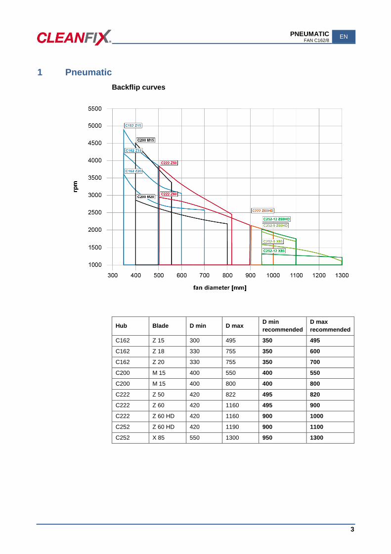
1 Pneumatic
Backflip curves
Hub Blade D min D max D min
recommended
D max
recommended
C162 Z 15 300 495 350 495 C162 Z 18 330 755 350 600 C162 Z 20 330 755 350 700 C200 M 15 400 550 400 550 C200 M 15 400 800 400 800 C222 Z 50 420 822 495 820 C222 Z 60 420 1160 495 900 C222 Z 60 HD 420 1160 900 1000
C252 Z 60 HD 420 1190 900 1100
C252 X 85 550 1300 950 1300
EN PNEUMATIC FAN C162/8
4
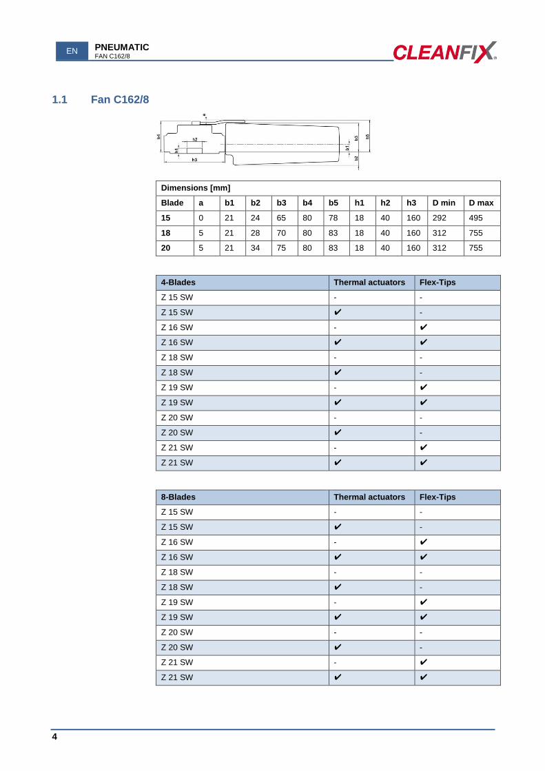
1.1 Fan C162/8
Dimensions [mm]
Blade a b1 b2 b3 b4 b5 h1 h2 h3 D min D max
15 0 21 24 65 80 78 18 40 160 292 495
18 5 21 28 70 80 83 18 40 160 312 755
20 5 21 34 75 80 83 18 40 160 312 755
4-Blades Thermal actuators Flex-Tips
Z 15 SW - -
Z 15 SW ✔ -
Z 16 SW - ✔
Z 16 SW ✔ ✔
Z 18 SW - -
Z 18 SW ✔ -
Z 19 SW - ✔
Z 19 SW ✔ ✔
Z 20 SW - -
Z 20 SW ✔ -
Z 21 SW - ✔
Z 21 SW ✔ ✔
8-Blades Thermal actuators Flex-Tips
Z 15 SW - -
Z 15 SW ✔ -
Z 16 SW - ✔
Z 16 SW ✔ ✔
Z 18 SW - -
Z 18 SW ✔ -
Z 19 SW - ✔
Z 19 SW ✔ ✔
Z 20 SW - -
Z 20 SW ✔ -
Z 21 SW - ✔
Z 21 SW ✔ ✔
PNEUMATIC FAN C200/9
EN
5
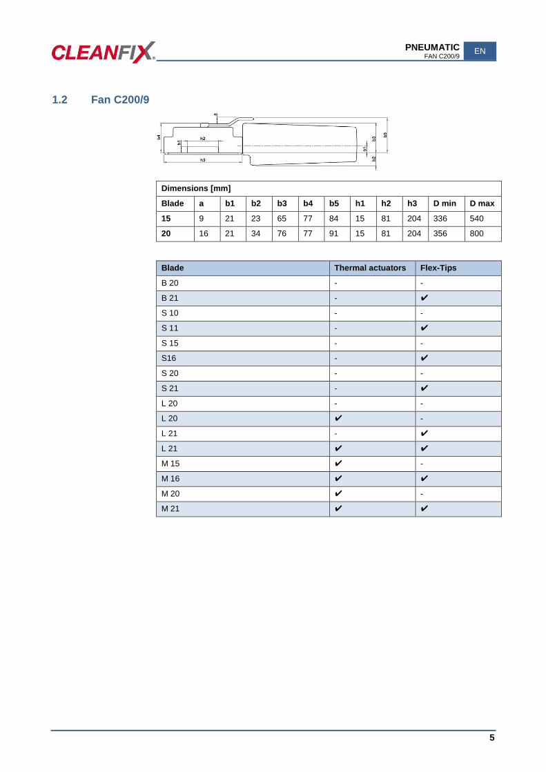
1.2 Fan C200/9
Dimensions [mm]
Blade a b1 b2 b3 b4 b5 h1 h2 h3 D min D max
15 9 21 23 65 77 84 15 81 204 336 540
20 16 21 34 76 77 91 15 81 204 356 800
Blade Thermal actuators Flex-Tips
B 20 - -
B 21 - ✔
S 10 - -
S 11 - ✔
S 15 - -
S16 - ✔
S 20 - -
S 21 - ✔
L 20 - -
L 20 ✔ -
L 21 - ✔
L 21 ✔ ✔
M 15 ✔ -
M 16 ✔ ✔
M 20 ✔ -
M 21 ✔ ✔
EN PNEUMATIC FAN C222/9
6
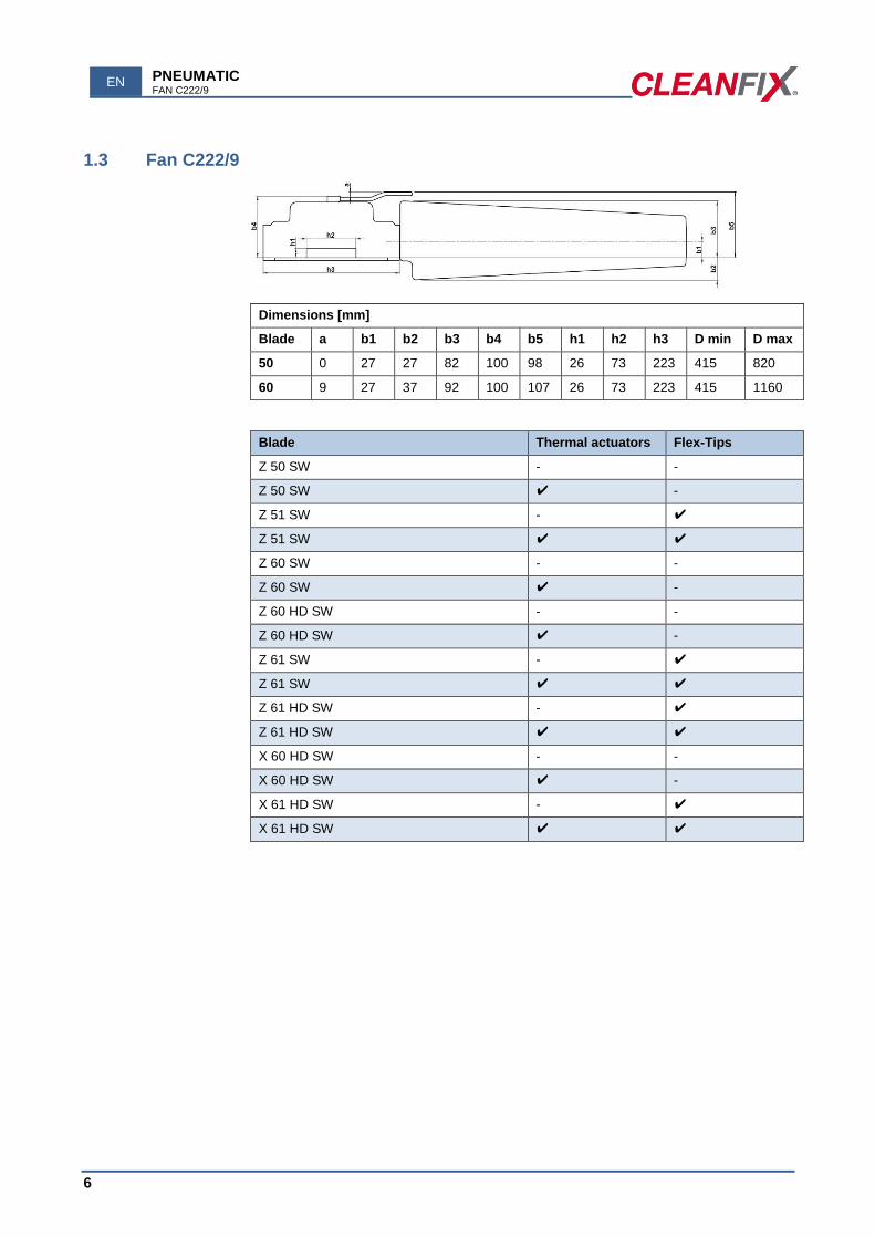
1.3 Fan C222/9
Dimensions [mm]
Blade a b1 b2 b3 b4 b5 h1 h2 h3 D min D max
50 0 27 27 82 100 98 26 73 223 415 820
60 9 27 37 92 100 107 26 73 223 415 1160
Blade Thermal actuators Flex-Tips
Z 50 SW - -
Z 50 SW ✔ -
Z 51 SW - ✔
Z 51 SW ✔ ✔
Z 60 SW - -
Z 60 SW ✔ -
Z 60 HD SW - -
Z 60 HD SW ✔ -
Z 61 SW - ✔
Z 61 SW ✔ ✔
Z 61 HD SW - ✔
Z 61 HD SW ✔ ✔
X 60 HD SW - -
X 60 HD SW ✔ -
X 61 HD SW - ✔
X 61 HD SW ✔ ✔

PNEUMATIC FAN C252/9
EN
7
1.4 Fan C252/9
Dimensions [mm]
Blade a b1 b2 b3 b4 b5 h1 h2 h3 D min D max
60 9 35 28 100 111 118 35 88 250 443 1190
85 26 35 40 116 111 135 35 88 250 523 1300
Blade Thermal actuators Flex-Tips
Z 60 SW - -
Z 60 SW ✔ -
Z 60 HD SW - -
Z 60 HD SW ✔ -
Z 61 SW - ✔
Z 61 SW ✔ ✔
Z 61 HD SW - ✔
Z 61 HD SW ✔ ✔
X 60 HD SW - -
X 60 HD SW ✔ -
X 61 HD SW - ✔
X 61 HD SW ✔ ✔
X 85 SW - -
X 85 SW ✔ -
X 86 SW * - ✔
X 86 SW * ✔ ✔
XB 85 SW - -
EN PNEUMATIC FAN C252/12
8
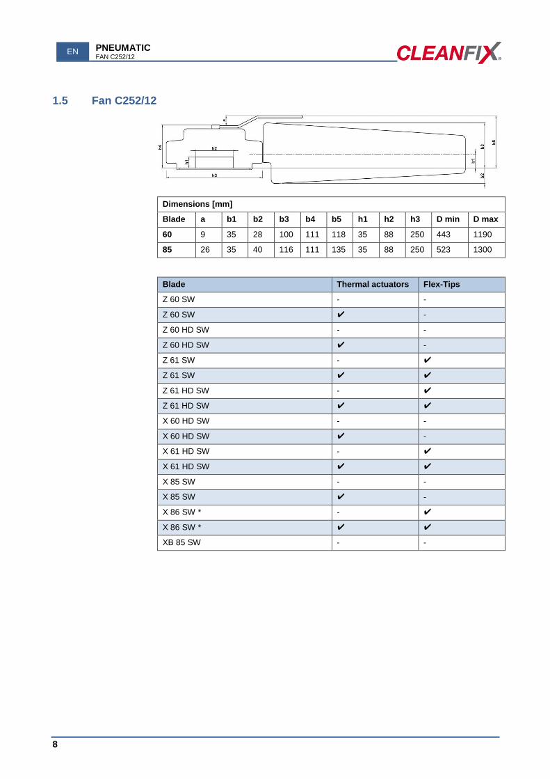
1.5 Fan C252/12
Dimensions [mm]
Blade a b1 b2 b3 b4 b5 h1 h2 h3 D min D max
60 9 35 28 100 111 118 35 88 250 443 1190
85 26 35 40 116 111 135 35 88 250 523 1300
Blade Thermal actuators Flex-Tips
Z 60 SW - -
Z 60 SW ✔ -
Z 60 HD SW - -
Z 60 HD SW ✔ -
Z 61 SW - ✔
Z 61 SW ✔ ✔
Z 61 HD SW - ✔
Z 61 HD SW ✔ ✔
X 60 HD SW - -
X 60 HD SW ✔ -
X 61 HD SW - ✔
X 61 HD SW ✔ ✔
X 85 SW - -
X 85 SW ✔ -
X 86 SW * - ✔
X 86 SW * ✔ ✔
XB 85 SW - -
PNEUMATIC FAN C220/9 (NO LONGER USED OR OFFERED FOR NEW INSTALLATIONS)
EN
9
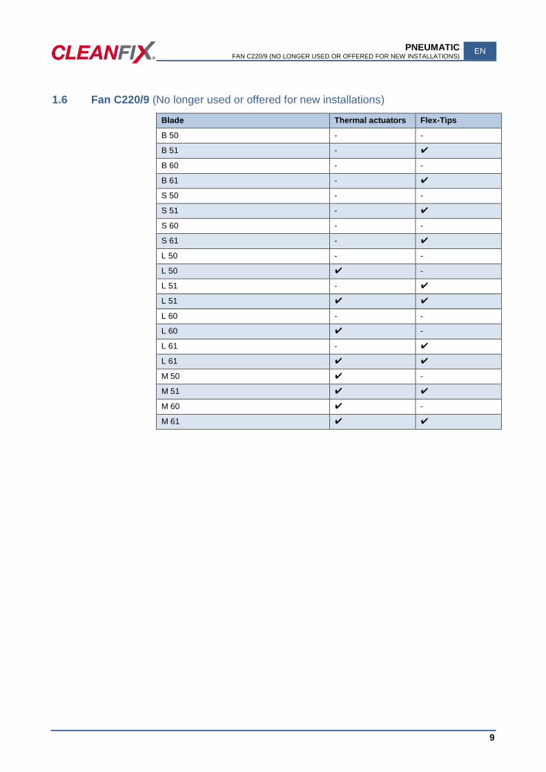
1.6 Fan C220/9 (No longer used or offered for new installations)
Blade Thermal actuators Flex-Tips
B 50 - -
B 51 - ✔
B 60 - -
B 61 - ✔
S 50 - -
S 51 - ✔
S 60 - -
S 61 - ✔
L 50 - -
L 50 ✔ -
L 51 - ✔
L 51 ✔ ✔
L 60 - -
L 60 ✔ -
L 61 - ✔
L 61 ✔ ✔
M 50 ✔ -
M 51 ✔ ✔
M 60 ✔ -
M 61 ✔ ✔
EN PNEUMATIC FAN C225/9 (NO LONGER USED OR OFFERED FOR NEW INSTALLATIONS)
10
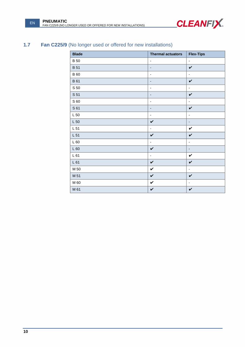
1.7 Fan C225/9 (No longer used or offered for new installations)
Blade Thermal actuators Flex-Tips
B 50 - -
B 51 - ✔
B 60 - -
B 61 - ✔
S 50 - -
S 51 - ✔
S 60 - -
S 61 - ✔
L 50 - -
L 50 ✔ -
L 51 - ✔
L 51 ✔ ✔
L 60 - -
L 60 ✔ -
L 61 - ✔
L 61 ✔ ✔
M 50 ✔ -
M 51 ✔ ✔
M 60 ✔ -
M 61 ✔ ✔

PNEUMATIC FAN C250/12 (NO LONGER USED OR OFFERED FOR NEW INSTALLATIONS)
EN
11
1.8 Fan C250/12 (No longer used or offered for new installations)
Blade Thermal actuators Flex-Tips
B 50 - -
B 51 - ✔
B 60 - -
B 61 - ✔
S 50 - -
S 51 - ✔
S 60 - -
S 61 - ✔
L 50 - -
L 50 ✔ -
L 51 - ✔
L 51 ✔ ✔
L 60 - -
L 60 ✔ -
L 61 - ✔
L 61 ✔ ✔
M 50 ✔ -
M 51 ✔ ✔
M 60 ✔ -
M 61 ✔ ✔
EN PNEUMATIC FAN C300/12 (NO LONGER USED OR OFFERED FOR NEW INSTALLATIONS)
12
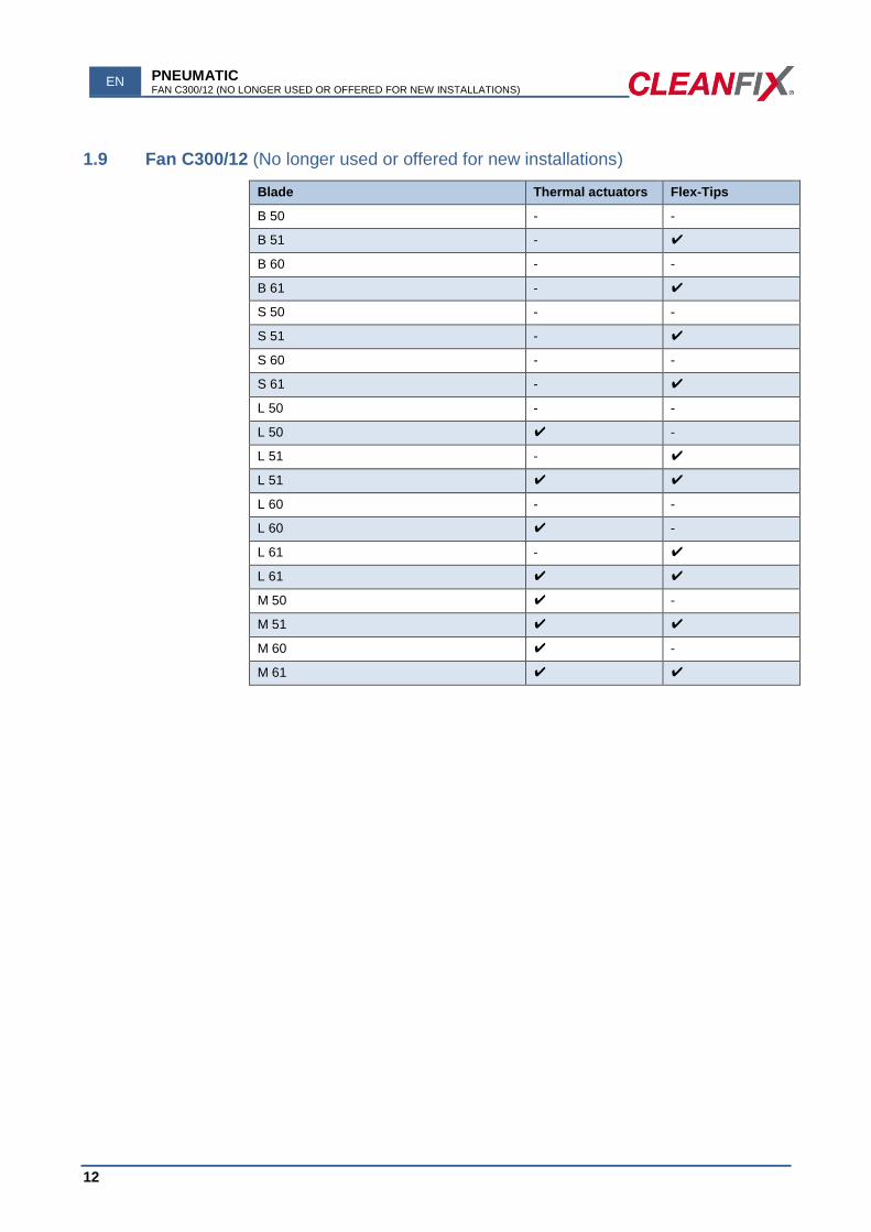
1.9 Fan C300/12 (No longer used or offered for new installations)
Blade Thermal actuators Flex-Tips
B 50 - -
B 51 - ✔
B 60 - -
B 61 - ✔
S 50 - -
S 51 - ✔
S 60 - -
S 61 - ✔
L 50 - -
L 50 ✔ -
L 51 - ✔
L 51 ✔ ✔
L 60 - -
L 60 ✔ -
L 61 - ✔
L 61 ✔ ✔
M 50 ✔ -
M 51 ✔ ✔
M 60 ✔ -
M 61 ✔ ✔
PNEUMATIC VALVE
EN
13
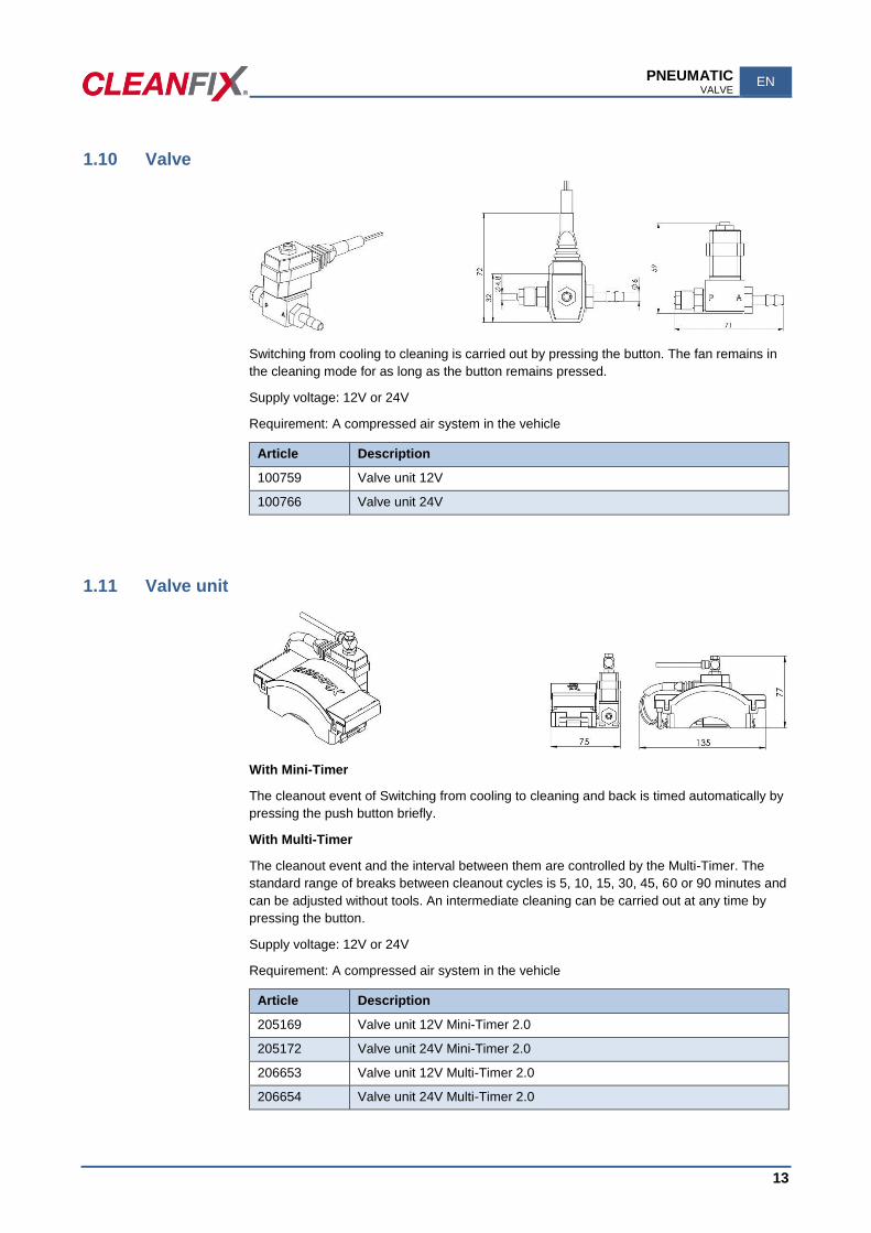
1.10 Valve
Switching from cooling to cleaning is carried out by pressing the button. The fan remains in
the cleaning mode for as long as the button remains pressed.
Supply voltage: 12V or 24V
Requirement: A compressed air system in the vehicle
Article Description
100759 Valve unit 12V
100766 Valve unit 24V
1.11 Valve unit
With Mini-Timer
The cleanout event of Switching from cooling to cleaning and back is timed automatically by
pressing the push button briefly.
With Multi-Timer
The cleanout event and the interval between them are controlled by the Multi-Timer. The
standard range of breaks between cleanout cycles is 5, 10, 15, 30, 45, 60 or 90 minutes and
can be adjusted without tools. An intermediate cleaning can be carried out at any time by
pressing the button.
Supply voltage: 12V or 24V
Requirement: A compressed air system in the vehicle
Article Description
205169 Valve unit 12V Mini-Timer 2.0
205172 Valve unit 24V Mini-Timer 2.0
206653 Valve unit 12V Multi-Timer 2.0
206654 Valve unit 24V Multi-Timer 2.0
EN PNEUMATIC COMPRESSOR UNIT
14
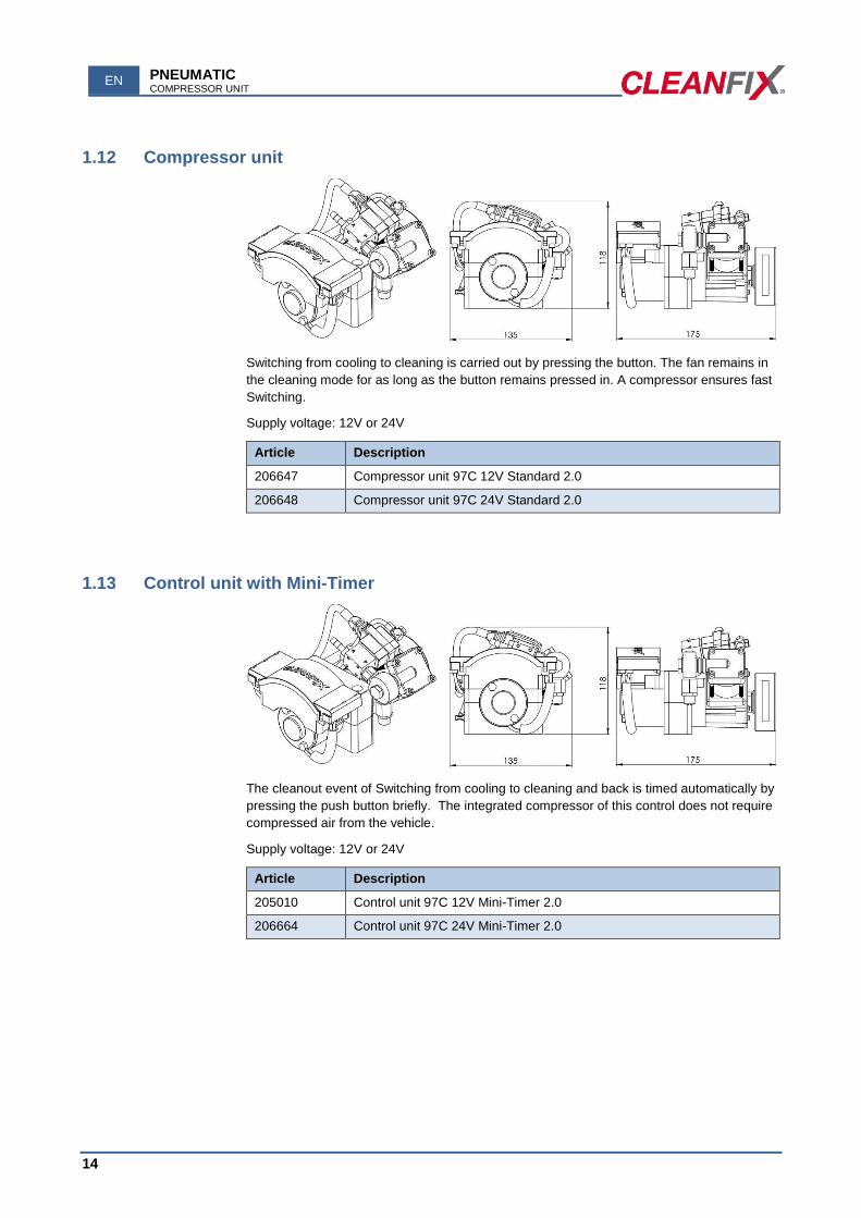
1.12 Compressor unit
Switching from cooling to cleaning is carried out by pressing the button. The fan remains in
the cleaning mode for as long as the button remains pressed in. A compressor ensures fast
Switching.
Supply voltage: 12V or 24V
Article Description
206647 Compressor unit 97C 12V Standard 2.0
206648 Compressor unit 97C 24V Standard 2.0
1.13 Control unit with Mini-Timer
The cleanout event of Switching from cooling to cleaning and back is timed automatically by
pressing the push button briefly. The integrated compressor of this control does not require
compressed air from the vehicle.
Supply voltage: 12V or 24V
Article Description
205010 Control unit 97C 12V Mini-Timer 2.0
206664 Control unit 97C 24V Mini-Timer 2.0

PNEUMATIC CONTROL UNIT WITH MULTI-TIMER
EN
15
1.14 Control unit with Multi-Timer
The cleanout event and the interval between them are controlled by the Multi-Timer. The
standard range of breaks between cleanout cycles is 5, 10, 15, 30, 45, 60 or 90 minutes and
can be adjusted without tools. An intermediate cleaning can be carried out at any time by
pressing the button. The integrated compressor of this control does not require compressed
air from the vehicle.
Supply voltage: 12V or 24V
Article Description
206649 Control unit 97C 12V Multi-Timer 2.0
206650 Control unit 97C 24V Multi-Timer 2.0
1.15 E-Box
The cleanout event and the interval between them is controlled by the Multi-Timer. The
standard range of breaks between cleanout cycles is 5, 10, 15, 30, 45, 60 or 90 minutes and
can be adjusted without tools. An intermediate cleaning can be carried out at any time by
pressing the button. The integrated compressor of this control does not require compressed
air from the vehicle. The components are housed in a protective PVC box.
Supply voltage: 12V or 24V
Article Description
205161 Control unit E-Box 97C 12V 2.0 double cable
205164 Control unit E-Box 97C 24V 2.0 double cable
EN HYDRAULIC E-BOX
16
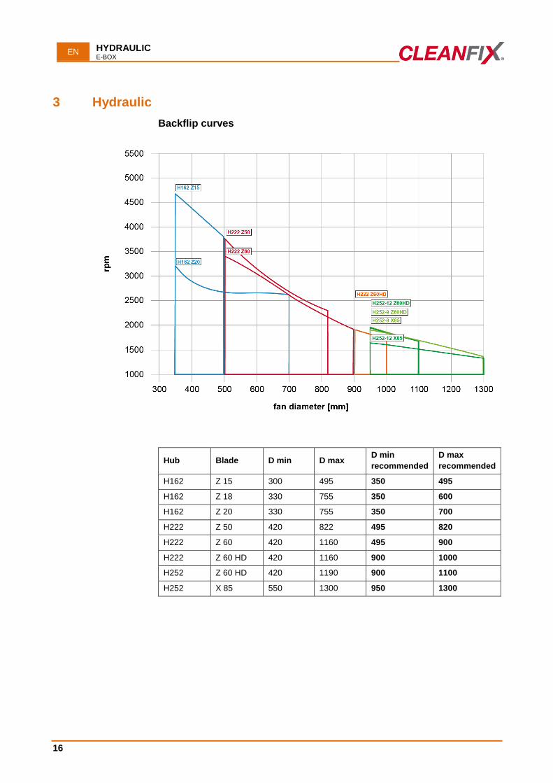
3 Hydraulic
Backflip curves
Hub Blade D min D max D min
recommended D max
recommended H162 Z 15 300 495 350 495 H162 Z 18 330 755 350 600 H162 Z 20 330 755 350 700 H222 Z 50 420 822 495 820 H222 Z 60 420 1160 495 900 H222 Z 60 HD 420 1160 900 1000 H252 Z 60 HD 420 1190 900 1100 H252 X 85 550 1300 950 1300
HYDRAULIC FAN H162/8
EN
17
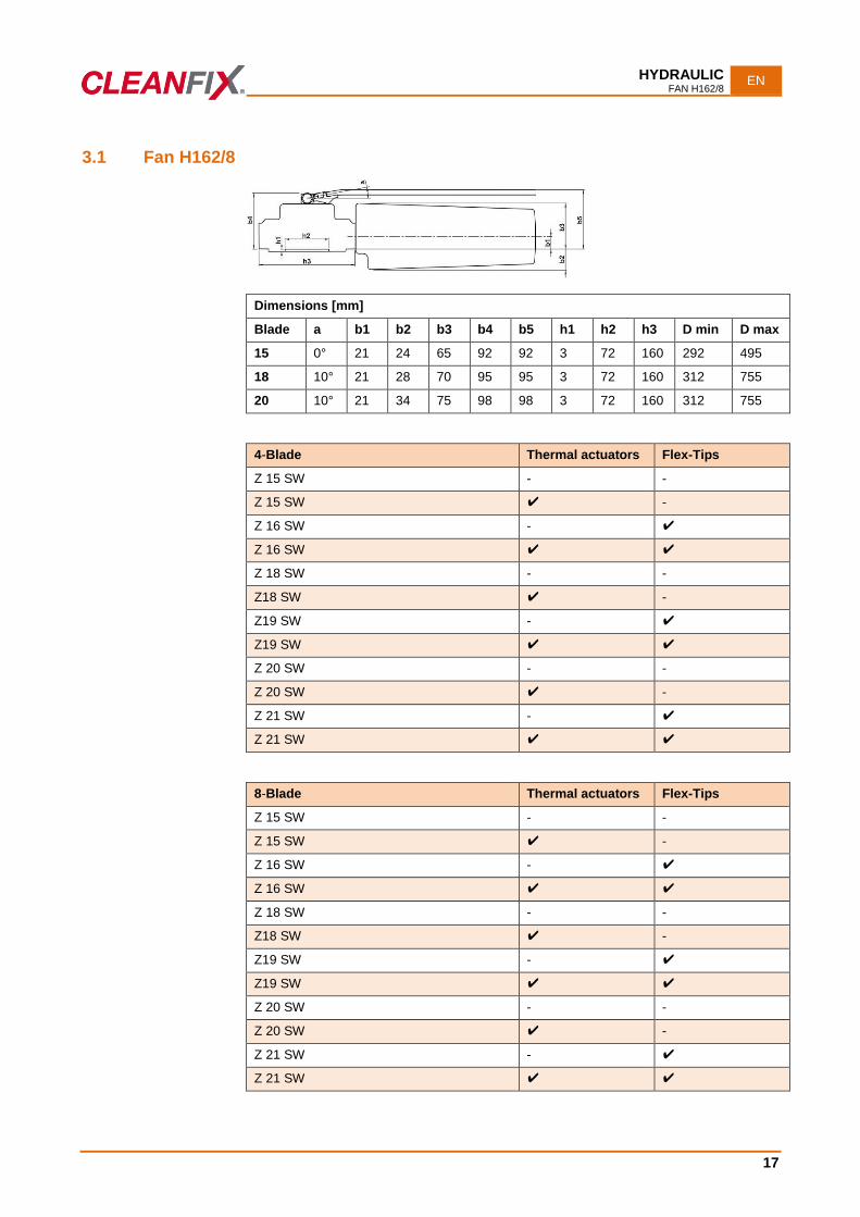
3.1 Fan H162/8
Dimensions [mm]
Blade a b1 b2 b3 b4 b5 h1 h2 h3 D min D max
15 0° 21 24 65 92 92 3 72 160 292 495
18 10° 21 28 70 95 95 3 72 160 312 755
20 10° 21 34 75 98 98 3 72 160 312 755
4-Blade Thermal actuators Flex-Tips
Z 15 SW - -
Z 15 SW ✔ -
Z 16 SW - ✔
Z 16 SW ✔ ✔
Z 18 SW - -
Z18 SW ✔ -
Z19 SW - ✔
Z19 SW ✔ ✔
Z 20 SW - -
Z 20 SW ✔ -
Z 21 SW - ✔
Z 21 SW ✔ ✔
8-Blade Thermal actuators Flex-Tips
Z 15 SW - -
Z 15 SW ✔ -
Z 16 SW - ✔
Z 16 SW ✔ ✔
Z 18 SW - -
Z18 SW ✔ -
Z19 SW - ✔
Z19 SW ✔ ✔
Z 20 SW - -
Z 20 SW ✔ -
Z 21 SW - ✔
Z 21 SW ✔ ✔
EN HYDRAULIC FAN H222/9
18
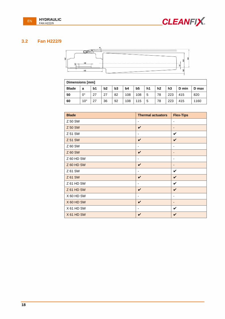
3.2 Fan H222/9
Dimensions [mm]
Blade a b1 b2 b3 b4 b5 h1 h2 h3 D min D max
50 0° 27 27 82 108 108 5 78 223 415 820
60 10° 27 36 92 108 115 5 78 223 415 1160
Blade Thermal actuators Flex-Tips
Z 50 SW - -
Z 50 SW ✔ -
Z 51 SW - ✔
Z 51 SW ✔ ✔
Z 60 SW - -
Z 60 SW ✔ -
Z 60 HD SW - -
Z 60 HD SW ✔ -
Z 61 SW - ✔
Z 61 SW ✔ ✔
Z 61 HD SW - ✔
Z 61 HD SW ✔ ✔
X 60 HD SW - -
X 60 HD SW ✔ -
X 61 HD SW - ✔
X 61 HD SW ✔ ✔
HYDRAULIC FAN H252/9
EN
19
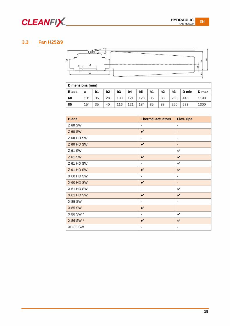
3.3 Fan H252/9
Dimensions [mm]
Blade a b1 b2 b3 b4 b5 h1 h2 h3 D min D max
60 10° 35 28 100 121 128 35 88 250 443 1190
85 15° 35 40 116 121 134 35 88 250 523 1300
Blade Thermal actuators Flex-Tips
Z 60 SW - -
Z 60 SW ✔ -
Z 60 HD SW - -
Z 60 HD SW ✔ -
Z 61 SW - ✔
Z 61 SW ✔ ✔
Z 61 HD SW - ✔
Z 61 HD SW ✔ ✔
X 60 HD SW - -
X 60 HD SW ✔ -
X 61 HD SW - ✔
X 61 HD SW ✔ ✔
X 85 SW - -
X 85 SW ✔ -
X 86 SW * - ✔
X 86 SW * ✔ ✔
XB 85 SW - -
EN HYDRAULIC FAN H252/12
20
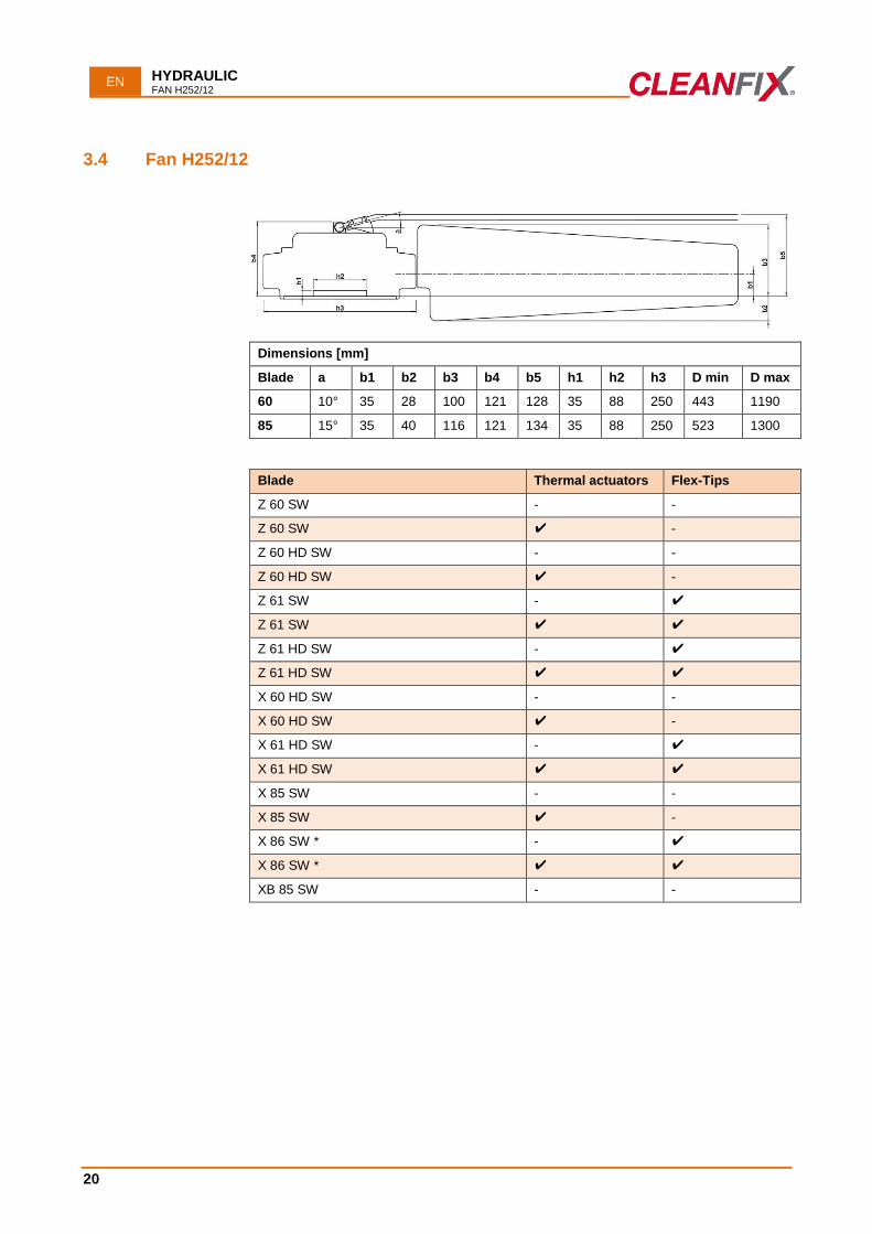
3.4 Fan H252/12
Dimensions [mm]
Blade a b1 b2 b3 b4 b5 h1 h2 h3 D min D max
60 10° 35 28 100 121 128 35 88 250 443 1190
85 15° 35 40 116 121 134 35 88 250 523 1300
Blade Thermal actuators Flex-Tips
Z 60 SW - -
Z 60 SW ✔ -
Z 60 HD SW - -
Z 60 HD SW ✔ -
Z 61 SW - ✔
Z 61 SW ✔ ✔
Z 61 HD SW - ✔
Z 61 HD SW ✔ ✔
X 60 HD SW - -
X 60 HD SW ✔ -
X 61 HD SW - ✔
X 61 HD SW ✔ ✔
X 85 SW - -
X 85 SW ✔ -
X 86 SW * - ✔
X 86 SW * ✔ ✔
XB 85 SW - -
HYDRAULIC VALVE UNIT
EN
21
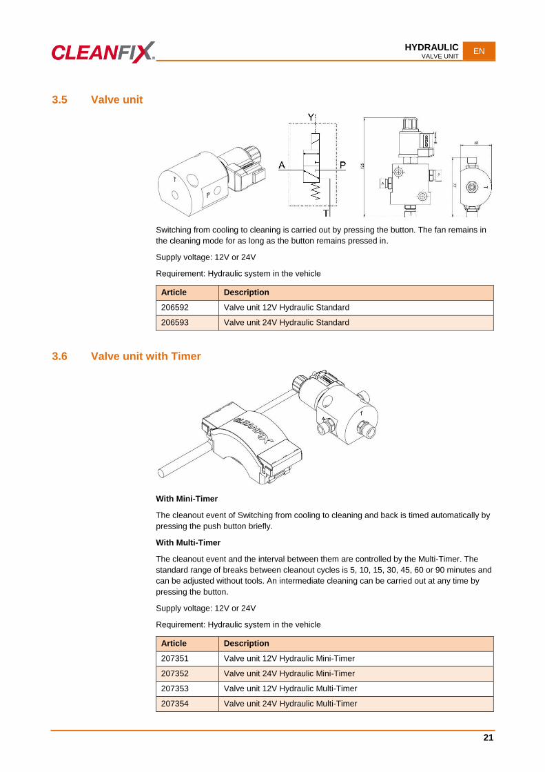
3.5 Valve unit
Switching from cooling to cleaning is carried out by pressing the button. The fan remains in
the cleaning mode for as long as the button remains pressed in.
Supply voltage: 12V or 24V
Requirement: Hydraulic system in the vehicle
Article Description
206592 Valve unit 12V Hydraulic Standard
206593 Valve unit 24V Hydraulic Standard
3.6 Valve unit with Timer
With Mini-Timer
The cleanout event of Switching from cooling to cleaning and back is timed automatically by
pressing the push button briefly.
With Multi-Timer
The cleanout event and the interval between them are controlled by the Multi-Timer. The
standard range of breaks between cleanout cycles is 5, 10, 15, 30, 45, 60 or 90 minutes and
can be adjusted without tools. An intermediate cleaning can be carried out at any time by
pressing the button.
Supply voltage: 12V or 24V
Requirement: Hydraulic system in the vehicle
Article Description
207351 Valve unit 12V Hydraulic Mini-Timer
207352 Valve unit 24V Hydraulic Mini-Timer
207353 Valve unit 12V Hydraulic Multi-Timer
207354 Valve unit 24V Hydraulic Multi-Timer

EN FLANGE
22
4 Flange
Category
1
2
3
4
5
FAN SPEED SENSOR 2.0
EN
23
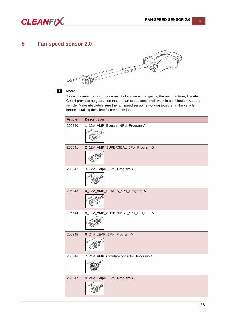
5 Fan speed sensor 2.0
Note:
Since problems can occur as a result of software changes by the manufacturer, Hägele
GmbH provides no guarantee that the fan speed sensor will work in combination with the
vehicle. Make absolutely sure the fan speed sensor is working together in the vehicle
before installing the Cleanfix reversible fan.
Article Description
206840 1_12V_AMP_Ecoseal_6Pol_Program-A
206841 2_12V_AMP_SUPERSEAL_5Pol_Program-B
206842 3_12V_Delphi_6Pol_Program-A
206843 4_12V_AMP_SEAL16_6Pol_Program-A
206844 5_12V_AMP_SUPERSEAL_5Pol_Program-A
206845 6_24V_LEAR_6Pol_Program-A
206846 7_24V_AMP_Circular-connector_Program-A
206847 8_24V_Delphi_6Pol_Program-A
EN FAN SPEED SENSOR 2.0
24
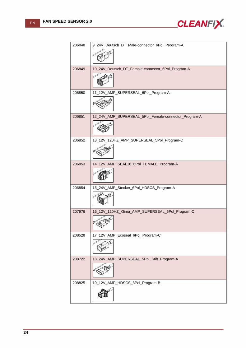
206848 9_24V_Deutsch_DT_Male-connector_6Pol_Program-A
206849 10_24V_Deutsch_DT_Female-connector_6Pol_Program-A
206850 11_12V_AMP_SUPERSEAL_6Pol_Program-A
206851 12_24V_AMP_SUPERSEAL_5Pol_Female-connector_Program-A
206852 13_12V_120HZ_AMP_SUPERSEAL_5Pol_Program-C
206853 14_12V_AMP_SEAL16_6Pol_FEMALE_Program-A
206854 15_24V_AMP_Stecker_6Pol_HDSCS_Program-A
207976 16_12V_120HZ_Klima_AMP_SUPERSEAL_5Pol_Program-C
208528 17_12V_AMP_Ecoseal_6Pol_Program-C
208722 18_24V_AMP_SUPERSEAL_5Pol_Stift_Program-A
208825 19_12V_AMP_HDSCS_8Pol_Program-B