20th aiaa advanced measurement and ground testing ... · aiaa-98-2506 experimental supersonic...
TRANSCRIPT

AIAA-98-2506
Experimental Supersonic CombustionResearch at NASA Langley
20th AIAA Advanced Measurementand Ground Testing Technology
ConferenceJune 15-18, 1998/Albuquerque, NM
For permission to copy or republish, contact the American Institute of Aeronautics and Astronautics1801 Alexander Bell Drive, Suite 500, Reston, VA 22091
R.C. Rogers, D.P. Capriotti, R.W. GuyNASA Langley Research Center,Hampton, VA
Drag
Thrust

1
American Institute of Aeronautics and Astronautics
AIAA 98-2506
EXPERIMENTAL SUPERSONIC COMBUSTIONRESEARCH AT NASA LANGLEY
R. Clayton Rogers* Diego P. Capriotti†, and R. Wayne Guy‡
NASA Langley Research CenterHampton, VA 23681
Abstract
Experimental supersonic combustion researchrelated to hypersonic airbreathing propulsion hasbeen actively underway at NASA LangleyResearch Center (LaRC) since the mid-1960’s.This research involved experimental investigationsof fuel injection, mixing, and combustion insupersonic flows and numerous tests of scramjetengine flowpaths in LaRC test facilities simulatingflight from Mach 4 to 8. Out of this research efforthas come scramjet combustor designmethodologies, ground test techniques, and dataanalysis procedures. These technologies haveprogressed steadily in support of the NationalAero-Space Plane (NASP) program and thecurrent Hyper-X flight demonstration program.During NASP nearly 2500 tests of 15 scramjetengine models were conducted in LaRC facilities.In addition, research supporting the engineflowpath design investigated ways to enhancemixing, improve and apply nonintrusivediagnostics, and address facility operation. Testsof scramjet combustor operation at conditionssimulating hypersonic flight at Mach numbers upto 17 also have been performed in an expansiontube pulse facility. This paper presents a review ofthe LaRC experimental supersonic combustionresearch efforts since the late 1980’s, during theNASP program, and into the Hyper-X Program._________________*Aerospace Engineer, Hypersonic Airbreathing PropulsionBranch, Senior Member AIAA.†Aerospace Engineer, Hypersonic Airbreathing PropulsionBranch, Member ASME.‡Head, Hypersonic Airbreathing Propulsion Branch, Senior
Member AIAA.
Copyright © 1998 by the American Institute of Aeronautics andAstronautics, Inc. No copyright is asserted in the United Statesunder Title 17, U. S. Code. The U.S. Government has aroyalty-free license to exercise all rights under the copyrightclaimed herein for Governmental Purposes. All other rights arereserved by the copyright owner.
Nomenclature
A AreaD DiameterG Combustor gap heightH Enthalpy; duct heightM Mach numberP Powerp PressureQ Volumetric flow rateq Dynamic pressureR Nozzle corner radiusT TemperatureX Axial coordinate∆F Fuel-on minus fuel-off axial forceα Volumetric ratioφ Equivalence ratio
Subscripts:
1 Facility test gas; scramjet inflowmax Maximum valuet Stagnation condition� Flight condition
Acronyms and Abbreviations:
8-Ft. HTT 8-Foot High Temperature TunnelAIM Aerothermodynamic Integration ModelAIS Airframe-Integrated ScramjetAHSTF Arc-Heated Scramjet Test FacilityAR Nozzle area ratioCDE Concept Demonstration EngineCFD Computational Fluid DynamicsCHSTF Combustion-Heated Scramjet Test
FacilityDCSCTF Direct-Connect Supersonic
Combustion Test FacilityDFX Dual-Fuel, eXperimental engineFE Hyper-X Flight EngineFFS Full-Flowpath SimulatorFPI Fuel Plume Imaging

2
American Institute of Aeronautics and Astronautics
HRE Hypersonic Research EngineHSM HYPULSE Scramjet ModelHXEM Hyper-X Engine ModelHXRV Hyper-X Research VehicleHYPULSE HYpersonic Pulse facilityLaRC Langley Research CenterLSTC Langley Scramjet Test ComplexNASP National Aero-Space PlaneP&W Pratt and WhitneyRD RocketdyneRST Reflected-Shock TunnelSAM Structural Assembly ModelSERN Single-Expansion Ramp NozzleSETb Shock-Expansion TubeSETn Shock-Expansion TunnelSTF Scramjet Test FacilitySXPE Subscale eXperimental Parametric
EngineSX-20 Subscale eXperimental, engine 20VPI Virginia Polytechnic InstituteX-30 NASP Experimental Vehicle
Introduction
Supersonic combustion research at the NASALangley Research Center (LaRC) began in the1960’s with analytical studies and somefundamental experiments. The rationale forstudying supersonic combustion has always beenwith application to airbreathing propulsion,specifically supersonic combustion ramjets(scramjets). With the support of contracted efforts,this basic experimental research led to theHypersonic Research Engine (HRE) project, whichwas started about 1964.1,2 Although the HRE didnot achieve the original intent of a test flight, theidea of hypersonic flight in the atmosphere withairbreathing propulsion systems has beencontinually pursued through experimental andcomputational research at LaRC. These researchefforts were focused on the clear need to achievegood installed performance with a propulsionsystem integrated into the vehicle flowpath. Theairframe-integrated scramjet (AIS) concept3
became the basic flowpath for both fundamentalstudies of fuel injection, mixing, and combustion,and for subscale engine tests in both LaRC andcontractors’ facilities. A review of this baselineresearch, including a summary of scramjet enginedesign methodology and test techniques as of1985 and an extensive bibliography has beendocumented in reference 4.
The review4 of the scramjet technology in the mid-1980’s indicated a firm fundamental basis for the
performance potential of dual-mode scramjets. Adual-mode scramjet is designed without theconventional ramjet second minimum area foroperation in both subsonic (ramjet) and supersoniccombustion modes. This fundamental level ofunderstanding was obtained from scramjetresearch that included established ground testtechniques for scramjet flowpaths andcomponents, maturing computational fluiddynamic (CFD) methods, and measurementdiagnostic systems. Supporting the engineflowpath ground tests were component tests andCFD analyses of inlets, fuel injection and mixing,combustion chemical kinetics and flameholding,and turbulence modeling which includedcombustion effects. Fuel injection and mixingstudies were done in both cold flow and direct-connect combustion environments. These studiesincluded the investigation of scramjet combustorconcepts with fuel injection parallel to the flowfrom the base of ramps.5 Although ground tests ofscramjet components and engines were limited byfacility operation to the mid-speed range of flightMach 4 to 8 simulation, some small scale tests ofhydrogen-air mixing and combustion had beendone at hypervelocity flow conditions simulatingflight at Mach 12 to 18. These tests,6 which wereconducted in pulse flow facilities where the testgas is heated and processed by a shock wave,indicated the potential for scramjet operation inhypersonic flight above Mach 10.
Drawing on the extensive technology baseavailable in the mid 1980’s, the National Aero-Space Plane (NASP) program began and becamethe focus for maturing and applying this scramjettechnology to a proposed flight research vehiclecapable of trans-atmospheric flight. Associatedwith this renewed national interest in scramjetswas a need for ground test facility capabilities thatspanned the flight regime.7 The outcome of NASPwas a significant leap in scramjet knowledge, bothin the form of scramjet engine test techniques anda database in the mid-speed flight (Mach 4 to 8)range of conventional ground test facilities, and inthe flight Mach 12 to 18 simulation tests in shocktunnel facilities. With the end of the NASPprogram in 1995, the hypersonic propulsionemphasis at LaRC shifted to assessment of theNASP database and providing scramjet flowpathdesign, testing, and operation support for theHyper-X Program.8 The Hyper-X Program willdemonstrate the free-flight operation of anairframe-integrated, hydrogen-fueled, scramjetflowpath in atmospheric flight at Mach 7 and 10between now and 2002.

3
American Institute of Aeronautics and Astronautics
The major LaRC contributions to supersoniccombustion technology and the application ofscramjets in hypersonic airbreathing propulsionsystems have been engine flowpath testing,ground test technique capability, and developmentof computational tools to benchmark the designmethods and provide data analysis tools.However, research activities have continued toexamine fuel injection schemes to enhance fuel-airmixing and to study alternative or combined cyclepropulsion systems. The purpose of this paper isto provide a review of experimental supersoniccombustion research efforts related to airbreathingpropulsion systems at LaRC since 1986. Thepaper will begin with an historical overview(including a summary of the 1986 paper4), reviewthe scramjet test facilities used and engine testsconducted during the NASP program, summarizethe scramjet component tests, and conclude withan overview of current experimental researchactivities.
Historical Perspectives
Any discussion of experimental supersoniccombustion research at LaRC must involve itsapplication to scramjets for hypersonicairbreathing propulsion. For nearly forty years,scramjet research activities at LaRC haveprogressed from the supporting technology thatled to the Hypersonic Research Engine (HRE)project to the current flight test program calledHyper-X. A review of scramjet research andprogress worldwide is given in reference 9.
Scramjet Base Research:
The history of scramjet technology development atLaRC is depicted by the time line in Figure 1. Thetime line shows a continuous path of Base-Research, which supported focused efforts like theHRE project from 1964 to 1974, the NASPprogram from 1987 to 1995, and the Hyper-X flightdemonstration program, ongoing since 1996. Key“Technology Areas” which were being studied ordeveloped are listed above the line, generally inchronological order. Below the time line arehighlights of “Test Experience.” Important testingevents or milestones are indicated and includescramjet test facilities (STF) coming on-line andengine flowpath test programs. Specific events ofnote are the airframe-integrated scramjet (AIS)concept in 1968, which was the basis for almost allof the subsequent supersonic combustion
research, and the fuel-air mixing scramjetcombustor design recipe, which was firstpresented and discussed in 1986.4 The variety andtype of engine tests conducted are indicated bythe ovals in the timeline; those which were directlysupportive of the NASP program are indicatedwithin the NASP oval.
All of the tests of scramjet engine flowpathsconducted in LaRC STF facilities from 1976 to thepresent are summarized in Table 1.10 Engine testactivity accelerated dramatically in support ofNASP and continued after NASP to provideclosure on open questions and concerns.Currently, testing is underway to provide Mach 5and 7 technology support to the Hyper-X Program.To date, 3445 tests have been conducted on 18scramjet engine models in numerous flowpathconfigurations, at mid-speed (flight Mach 4 to 8)conditions in LaRC facilities. Assuming an averagetest condition simulating Mach 5 flight speed(about one mile per second) and a nominal testduration of about 20 seconds of on-point data(typical for the STF’s), these tests are equivalentto about three trips around the world in scramjetoperational experience.
Basis for NASP:
The year 1986 provides a distinct break point inthe discussion of scramjet research because ofthe review documented in Reference 4, and thebeginning of the NASP program. That review ofthe ground test and supporting research on themodular, airframe-integrated, dual-mode scramjetflowpath presented a summary of the direct-connect tests of scramjet combustor componentsand engine flowpath tests (see Table 1), andincluded an extensive bibliography from LaRC andother groups. The original concept for scramjetcombustors was to inject hydrogen fuel into thesupersonic air stream from orifices flush mountedon the walls or on the sides of struts, which alsoprovided internal inlet compression.3,11 Examplesof the types of scramjet engine flowpath hardwareused to study scramjet operation in the 1976-87period are shown in cross section views in Figure2. These engines are all of the modular concept,with sidewall compression, for operation betweenMach 4 and 8 flight. Shown in the figure are the“three-strut engine,” the “strutless parametricengine,” and the “step-strut engine.” Tests wereconducted as indicated in Table 1. The outcome ofthese tests helped establish the Langley scramjetcombustor design methods.4

4
American Institute of Aeronautics and Astronautics
The thrust performance results from tests of theseengine configurations at simulated flight at Mach 4and 7 are summarized in Figure 3. The solid linesare theoretical predictions from streamtubeanalyses using an empirical fuel mixing schedulebased on numerous direct-connect test results.Also shown are estimates of vehicle drag. Theperformance potential demonstrated in theseground test results, the confirmation of designmethods, the LaRC supersonic combustionground test experience and capability, and theapplication of analytical tools and models,contributed significantly to the decision to proceedwith the NASP program. The contribution andcollaboration of other government researchprograms sponsored by the Navy and Air Forceculminated in the initiation of the NASP program in1987.
The NASP Era
During the NASP program, the majority ofscramjet work at LaRC involved engine flowpathtests, as indicated in Figure 1 and listed in Table1. Ten engine models in multiple configurationswere studied in 1549 tests from 1987 to 1994.However, basic research studies of scramjetphenomena continued. These studies includedtransverse fuel injector operation,12,13 injectorconcepts for fuel mixing enhancement,14-17
application of nonintrusive measurement systemsfor supersonic combustion,18-20 and nozzleperformance effects.21,22 Ground test capability attrue flight stagnation enthalpy also was needed tosimulate the hypervelocity conditions of trans-atmospheric flight. This need led to thereactivation of several pulse facilities, amongwhich was the NASA HYpersonic PULSE(HYPULSE) shock-expansion tube (SETb), thatcame on-line in 1988.23-25
The remaining sections of this paper will includehighlights of the experimental supersoniccombustion work at LaRC from 1986, including areview of the test facilities, engine flowpath tests,scramjet component tests and supportingresearch, and some areas of experimentalscramjet research of current interest.
Test Facilities.Schematic diagrams of the five major test facilitiesthat comprise the Langley Scramjet Test Complex(LSTC) are presented in Figure 4. Details of thefacilities’ operation, instrumentation, and usageare presented in Reference 10. All of the facilities
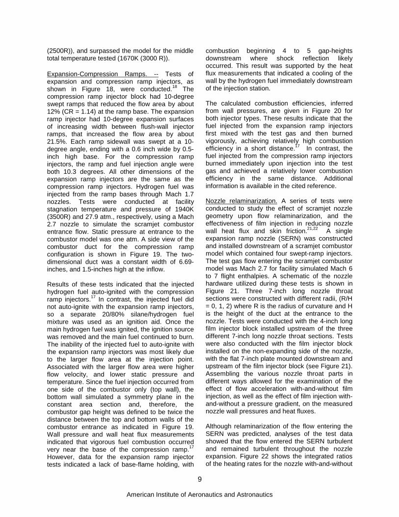
are located at LaRC except for the HYPULSEfacility, which is located at and operated by GASL,Inc. under contract to NASA. A summary of thetest facilities is given in Table 2, which includesinformation about the flow heating method, nozzleexit size, and test section dimensions. Thealtitude-flight Mach number operational envelopesof the LSTC facilities are given in Figure 5.Included on the map are lines of constantstagnation pressure and enthalpy and lines ofdynamic pressure along the airbreathing flightcorridor.
Engine Test Facilities:
The Arc-Heated Scramjet Test Facility (AHSTF),has been in operation since 1976.26 The test gasis obtained by heating air with an electric arc (upto 13MW), and adding unheated air to achieve thedesired stagnation pressure and enthalpy. Thefacility can replicate the stagnation enthalpyconditions of scramjet captured air at flight Machnumbers from 4 to 8. Maximum facility stagnationpressure is about 40 atm. Typical run times varybetween about 60 to 30 seconds at flight Mach 4and 8 conditions, respectively.
The Combustion-Heated Scramjet Test Facility(CHSTF),27 in operation since 1978, uses avitiated-air test gas which is obtained by hydrogencombustion, with oxygen replenishment to keepthe oxygen concentration at 21%. The facility candeliver a test gas at stagnation enthalpy simulatingMach 3.5 to 6.0 flight speeds. Maximum facilitystagnation pressure is 34 atm. Typical run timesare 25 seconds duration.
The 8-Foot High Temperature Tunnel (8-Ft. HTT)was upgraded for propulsion testing in 1993 withthe provision for oxygen replenishment of themethane combustion-heated test gas.28 Thefacility test conditions can simulate Mach 4 to 7flight enthalpy. Maximum facility stagnationpressure is about 136 atm. at Mach 7. Typical runtimes are about 30 seconds on point. Calibrationinformation for scramjet testing is provided inReference 29.
Component Test Facilities:
The Direct-Connect Supersonic Combustion TestFacility (DCSCTF) is a parallel test cell with theCHSTF and has been the site for testing scramjetfuel injectors, combustor configurations, inletisolators, and nozzle expansions since the late

5
American Institute of Aeronautics and Astronautics
1960’s. The vitiated-air test gas is produced byhydrogen combustion in air with oxygenreplenishment to keep the test gas oxygen contentat 21%. Stagnation conditions are limited to about40 atm. and 2100K (3800 R), which correspondsto flight Mach 7.5.
Hypervelocity Testing:
The NASA HYPULSE facility,23 operating in theshock-expansion tube (SETb) mode, provideshypervelocity test capability for fuel injectors andcombustors at simulated flight conditions fromMach 12 to 17. In this mode of operation, the testgas is heated and accelerated by a shock wave tothe static flow conditions corresponding toscramjet combustor entrance at the desired flightMach number.
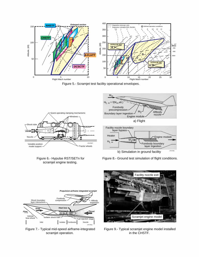
Recently, HYPULSE has been upgraded toincrease the operational flight envelope in Machnumber and dynamic pressure simulation.30-33 Theupgrade included the installation of a 175:1 arearatio (AR) axisymmetric nozzle, with an exitdiameter of 66.67 cm (26.25 inches), whichenables operation as a reflected shock tunnel(RST) for scramjet engine testing at simulatedconditions from about flight Mach 5 to 12. The newtest section for scramjet engine testing is shown inthe sketch in Figure 6. The expanded testenvelope is shown in Figure 5, denotedHYPULSE-RST. Conditions at the exit of the AR-175 nozzle are given in Table 2. These conditionsoverlap the test envelopes of the other blowdownSTF’s, and will provide testing at Mach 10 insupport of Hyper-X. Although not yet fullyimplemented, the upgrade offers the potential forHYPULSE operation in a shock-expansion tunnel(SETn) mode for scramjet engine tests atsimulated flight speeds from Mach 12 to 18+.Because test times are short, on the order of a fewmilliseconds, the test hardware remains cold, andoptical diagnostics of the combustor internal floware easily implemented.
Engine Tests
Scramjet engine flowpath tests conducted in LSTCfacilities are listed in Table 1. Much of the dataand results have limited access, which preventsdiscussion of the test details. Prior to the NASPprogram, 963 tests were conducted on threeengine configurations over a twelve-year period.During the NASP program, testing increaseddramatically with 1549 tests conducted on tenengine models and numerous configurations over
a four-year period. After NASP ended, NASA-ledtesting of NASP engine models, the SXPE andCDE, continued with 151 tests conducted. Inaddition, 400 tests were conducted using theLaRC Parametric Engine, and 132 tests wereconducted using a Rocketdyne NASP enginemodified for hydrocarbon fuel (ethylene). Recently,in support of the Hyper-X program, over 250 testshave been completed using the DFX engineinstalled in the AHSTF. Quantities typicallymeasured in these tests include wall pressures,wall heat transfer, net axial force, mass flow rates,and in-stream pitot pressures. The sub-scaleengine models are typically non flight-weight testarticles of heat sink thermal design.
General subscale engine testing methodology34 isdepicted in Figures 7 and 8. Figure 7 illustrates thetypical operation of a dual-mode AIS in the mid-speed (flight Mach 4-8) regime (where transitionfrom subsonic to supersonic burning occurs), andidentifies the associated physical processes ofimportance. The vehicle sketch inset in the figureshows the concept of airframe-integrated modularengines. The elements key to this discussion arethe fuel injection, mixing, and combustion, and theisolation of the heat release process from theinternal inlet operation. Replication of theseprocesses in a ground test is illustrated in Figure8, where the principal simulation parameters arestagnation enthalpy (at the flight Mach number),and Mach number and static pressure entering theengine. Typical ground test facilities simulate thecompression process due to the vehicle forebodyby heating the test gas to the stagnation enthalpycorresponding to the flight Mach number, and thenexpanding the test gas to the lower aerodynamicMach number approaching the inlet of the engine.Typically, the stagnation enthalpy and inflow Machnumber will be matched, but the inflow staticpressure may be low, which corresponds to alower dynamic pressure simulation. In general, thegoals of subscale engine tests are to determineengine operability, inlet performance, isolatorperformance, fuel-air mixing and flameholding,combustion efficiency, and to maximize themeasured thrust stand performance, ∆F.
Pre-NASP
Prior to the NASP program, scramjet combustionresearch at LaRC focused upon the three-dimensional, fixed-geometry sidewall compressionengine concept. This engine utilized swept wedgesidewalls to compress the flow with various fuelinjector and flameholder designs. Three different

6
American Institute of Aeronautics and Astronautics
configurations of this engine were tested (seeFigure 2): the three-strut, the strutless parametricand the step-strut. The three-strut engine was arectangular (swept) sidewall compression engine.Three internal swept struts further compressed thecaptured test gas and injected hydrogen fuel intothe flow. The parametric engine was a versatiletest article, which was changed into differentconfigurations without removal from the testfacility. The parametric engine was rectangularand used a sidewall compression inlet. The step-strut engine was the parametric engine with thesidewall leading edges unswept and a swept strutwith a "stepped" leading edge. Test resultsachieved with these engines contributed to thebeginning of the NASP program, as previouslyindicated.
NASP, 1987-1990
The first scramjet engine model built and testedduring the NASP program was the GovernmentBaseline engine, which had 114 tests in variousconfigurations in the CHSTF at simulated flightMach 4 conditions. The objective of these testswas to identify any major problems with theramjet/scramjet engine cycle that would hinder theprogress of the NASP program. The governmentbaseline engine had variable-geometry thatallowed the engine to be tested as a classicmechanically throated ramjet. This engineachieved fuel ignition by using conventional sparkplugs rather than the pyrophoric 20% silane inhydrogen fuel mixture of most of the subsequentengine tests.35
During these early years of the NASP program,independent scramjet engine designs were testedin the CHSTF and AHSTF by the major enginecompanies (Pratt & Whitney (P&W) andRocketdyne (RD)) in order to create a dual-modescramjet. A total of 517 tests were completedusing the Rocketdyne "A" series of engines in bothLSTC facilities. (See Table 1.) The P&W engine“C” had 233 tests in the same two LSTC facilities.A photo of this engine installed in the CHSTF isshown in Figure 9. Also during this period, 359tests were conducted in the CHSTF of the GenericHigh Speed Engine (GHSE) model B-1, which wasdesigned by the Johns Hopkins University AppliedPhysics Laboratory (JHU-APL). The GHSE was arectangular engine composed of an opposed dual-ramp inlet, an isolator, and a combustor with aconstant area section followed by a divergingsection.36 Tests were conducted at simulated flightMach numbers of 4.3 and 5.0. The RD, P&W, and
JHU/APL engine tests were all focused towardsdemonstration of high performance and goodoperability characteristics in the mid-speed flightrange with engine flowpaths designed for trans-atmospheric flight.
NASP, 1990-1994
The first engine built and tested following teamingof the NASP engine contractors (1990) was theSX-20 (Subscale eXperimental-engine 20). Testsof this engine in various configurations wereconducted in the AHSTF at simulated flight Machnumbers of 7 to 8. Results of these and otherengine and engine component tests influenced thefinal NASP engine design, which was intended topower the X-30 experimental airplane. A 12.5%scale version of this engine flowpath wasconstructed and named the SubscaleeXperimental Parametric Engine, (SXPE). Tests ofthis engine were conducted in the AHSTF atsimulated flight Mach numbers of 5 to 8.
A larger engine, the Concept DemonstrationEngine (CDE), was built for testing in the 8-Ft.HTT. The CDE flowpath was designed for highspeed flight up to Mach 25. The CDE test enginewas of heat-sink thermal design that was a 30%photographic scale of the middle module of theNASP X-30 engine flowpath. Twenty-four tests ofthe CDE were conducted in the 8-Ft HTT at asimulated Mach 7 flight condition, but at 60% ofthe flight dynamic pressure. The test objectiveswere to demonstrate performance and operabilitylimits of the large-scale integrated scramjet inorder to verify flowpath design methods forapplication to flight.
Figure 10 shows a schematic representation of thegeometric relationship between the CDE, SXPE,and the X-30 flight engine flowpaths, and includesthe available ground test simulation parametersrelative to the flight environment at Mach 7. Thefigure shows that although each facility was ableto simulate the correct flight stagnation enthalpy,the simulated flight dynamic pressures were low,and consequently, the Reynolds numbersimulations of both facilities were low whencompared with flight. In addition, the test gases ofthe facilities contain contaminants-- water vaporand carbon dioxide in the 8-Ft. HTT and smallamounts of NOx in the AHSTF. Some discussionof the issues of ground test simulation regardingthe X-30 engine, the CDE, and the SXPE is givenin Reference 34. The SXPE and CDE testsprovided a direct comparison of essentially the

7
American Institute of Aeronautics and Astronautics
same supersonic combustor flowpath at twogeometric scales in two facilities from whichground test simulation concerns could beexamined. These concerns include the effects ofsimulation parameters relevant to scramjet engineflowpath operation, including the Mach, Reynolds,and Stanton numbers, first and second Damkohlernumbers, and wall enthalpy ratio.37 The outcomefrom the two test series indicated the need tounderstand the effects of geometric scale,dynamic pressure, facility test gas composition,and viscous effects when designing and testingscramjet engines for hypersonic flight.
Post NASP
Testing of the SXPE and CDE engines continuedafter the end of the NASP program to furtherinvestigate specific performance characteristicsand to gain an understanding of the differencesobserved in the test data. During this effort, 124tests were conducted with the SXPE installed inthe AHSTF and 27 tests were conducted with theCDE installed in the 8-Ft HTT.
Following the NASP tests, a NASA test programwas initiated to investigate fundamental issuesgoverning dual-mode scramjet engineperformance. The test article chosen for thisprogram was the LaRC Strutless ParametricEngine. This engine model was installed in theCHSTF and 400 tests were conducted in variousconfigurations to examine inlet-combustorinteraction, captured airflow profile, and test gascontamination effects. The engine was tested withtwo different sidewall compression inlets havingthe same projected full capture area. One inlet hadboth sidewall leading edges swept backward andthe other had one sidewall leading edge sweptforward and the other backward. Tests wereconducted over a simulated flight Mach numberrange of 4.0 to 5.5 with inlet contraction ratios of 5and 6. During some tests, ingestion of the vehicleforebody boundary layer was simulated by testingwith the engine capturing the facility nozzleboundary layer. The engine was tested as aclassic mechanically throated ramjet, and as athermally throated dual mode scramjet. Hydrogenfuel was injected from various locations throughsonic perpendicular sidewall orifices. Additionaldetails of these tests are documented inReference 38.
Although most all testing at LaRC has beenconducted using hydrogen fuel, some operation ofhydrocarbon-fueled scramjets has been
explored.39 That investigation reports on tests of aRD engine model in the CHSTF using ethylene asa generic hydrocarbon fuel. Test conditionssimulated flight Mach 4 (stagnation temperature911K (1640 R)) at 1000 psf dynamic pressure.Tests were conducted with fuel injected fromseveral discrete locations and in combinations withother injectors to assess thrust performance andcombustor-inlet interaction. For comparison withselected ethylene tests, some tests were madewith hydrogen fuel.
The hydrocarbon engine testing included anassessment of: 1) fuel ignition and flameholding,2) injector location, 3) pilot gas quantity onperformance, and 4) fuel type on performance. A20/80% (molar) mixture of pyrophoric gas (silaneand hydrogen) was used for ignition of the fuel.However, results of the tests indicated that, for thescale and conditions of the tests, combustion withethylene fuel required piloting with the silane fuelmixture. Hydrogen fuel operation was achievedunpiloted, using the silane fuel mixture for ignitiononly. A comparison summary of these results isshown in Figure 11. The performance parameter∆F is the difference in the measured loads on aforce balance between fuel-on and fuel-offoperation. The performance achieved with pilotedcombustion of ethylene and systematic variation offuel injection was comparable with the bestperformance for hydrogen fuel.
Scramjet Component Tests
DCSCTF:
Experimental tests of supersonic combustorcomponents have been conducted using directconnect hardware to acquire data to study basiccombustor performance for simple geometries andto explore diagnostics. The following sections giveexamples of some of these activities.
Plasma Torch. -- Tests to study the application ofa plasma torch as an ignition source for hydrogen-fueled supersonic flow fields were conducted atnominal Mach 2 and one atmosphere staticpressure combustor entrance conditions,simulating about flight Mach 4 (Tt = 780 - 1000K(1400 - 1800R)).40,41 Figure 12 shows a schematicdiagram of the combustor duct. The five 0.05-inchdiameter, perpendicular injectors, supplied a smallamount of hydrogen fuel to pilot the flameholdingregion behind the 0.15-inch high step. The three0.1-inch diameter perpendicular injectors, located

8
American Institute of Aeronautics and Astronautics
downstream of the step, fueled the scramjetcombustor duct. The plasma torch, shown inFigure 13, was installed in the separated flowregion downstream of a rearward-facing step. Theplasma torch was designed to operate with agaseous mixture of argon and hydrogen at powerlevels of approximately 1kW. The mixture wassupplied to the plasma torch at various volumetricratios (α). The mass flow through the torch wasapproximately 0.01 percent of the total mass flowthrough the test article, with the hydrogen flowcomprising only 0.1 percent of the total fuel flow.Nominal fuel equivalence ratios for the upstreamand downstream injectors were 0.042 and 0.26,respectively. Pressure data on the top and bottomwalls were used to estimate the combustionefficiency as a function of facility and plasma torchparameters.
Figure 14 shows a plot of the measured pressuredistributions for tests without fuel injection, forhydrogen-fueled tests with the argon-hydrogenplasma, and for two tests with different amounts ofa pyrophoric fuel mixture (20% silane (SiH4) inhydrogen). This silane fuel mixture was injectedfrom an orifice at the same location and of similarsize to the plasma torch. The pressuredistributions for the fueled tests are quite similar,indicating that the ignition and flameholdingcharacteristics for the argon-hydrogen plasma aresimilar to those with the pyrophoric fuel mixture.However, the data indicated that the pyrophoricfuel mixture was only able to ignite the primary fuelfor facility stagnation temperatures greater than990K (1780R), whereas the argon-hydrogenplasma was able to ignite the primary fuel for allstagnation temperatures tested, 290 to 990K (520- 1780 R). Results of the test series indicated thatthe argon-hydrogen plasma torch was an effectiveigniter for a scramjet combustor when used inconjunction with flameholder geometry.
Swept-Ramp Injectors. -- Mixing and combustioncharacteristics of wall-mounted ramps with basefuel injection were studied in the DCSCTF atconditions simulating Mach 5 to 7 flight.14-16 Theobjective of the tests was to explore theenhancement of the fuel/air mixing and thusreduce the length of a scramjet combustor. Sincefuel injection directed downstream is useful toextract energy from hydrogen fuel that has beenused to cool the engine and airframe, techniquesto enhance the relatively slow mixing of parallelfuel jets were investigated. The tests wereconducted at Mach 2 and 3 combustor entranceconditions and the hydrogen fuel was injected at
Mach 1.7 from the bases of swept and unsweptwall-mounted ramps. As shown in Figure 15, theramps were inclined 10 degrees relative to thewall. During all test series, the simulated flightMach number was varied from 5 to 7 by changingthe facility stagnation temperature. The exit staticpressure was maintained at 1 atmosphere with theMach 2 nozzle and 12 psia with the Mach 3nozzle. Also shown in Figure 15 are a schematicof the ramp fuel-injector geometries and sketchesindicating the shock positions for the twocombustor entrance Mach numbers tested.Additional information about the design and testingis available in the cited references.
One-dimensional analyses of the wall pressuredata were performed to determine the combustionefficiency distributions that are shown in Figures16 and 17 as a function of fuel equivalence ratiofor the Mach 2 and Mach 3 tests, respectively. Forcomparison, the curves labeled A and B indicatethe predicted mixing performance using theLangley mixing model. Curve A is forperpendicular sonic injection and Curve B is forparallel sonic injection. The combustion andmixing efficiencies shown in Figures 16 and 17were calculated at an X/G of 12.5 to be consistentwith the model definition of gap height, G, which isdefined as the combustor height at the injectorlocation. At the Mach 2 condition, the performanceof the swept injectors (Fig. 16) was nearly equal tothe mixing predicted by the perpendicular injectionmixing model; however, the performance of theunswept injectors was closer to the parallelinjection mixing model. It was observed also thatthe swept injectors do not show a dependence onthe facility stagnation temperature whereas, theunswept injector results indicated decreasingperformance as the stagnation temperature wasincreased.
For the Mach 3 tests (Figure 17), the sweptinjector performance equaled and surpassed themixing model predicted values for perpendicularinjection (curve A) with facility test gas at Tt = 1670- 1900K (3000 - 3500R). The poorer calculatedcombustion efficiency for the unswept injectors atTt = 1940K (3500R) suggests an absence of aflame-holding region at the ramp base. This lack offlameholding could be attributed to the nearmatching of the fuel jet and test gas velocities atthis test point.15 However, the unswept injectorsperformance was nearly equal to the mixing modelprediction for the perpendicular injection at thelowest facility temperature tested (1390K
9
American Institute of Aeronautics and Astronautics
(2500R)), and surpassed the model for the middletotal temperature tested (1670K (3000 R)).
Expansion-Compression Ramps. -- Tests ofexpansion and compression ramp injectors, asshown in Figure 18, were conducted.18 Thecompression ramp injector block had 10-degreeswept ramps that reduced the flow area by about12% (CR = 1.14) at the ramp base. The expansionramp injector had 10-degree expansion surfacesof increasing width between flush-wall injectorramps, that increased the flow area by about21.5%. Each ramp sidewall was swept at a 10-degree angle, ending with a 0.6 inch wide by 0.5-inch high base. For the compression rampinjectors, the ramp and fuel injection angle wereboth 10.3 degrees. All other dimensions of theexpansion ramp injectors are the same as thecompression ramp injectors. Hydrogen fuel wasinjected from the ramp bases through Mach 1.7nozzles. Tests were conducted at facilitystagnation temperature and pressure of 1940K(3500R) and 27.9 atm., respectively, using a Mach2.7 nozzle to simulate the scramjet combustorentrance flow. Static pressure at entrance to thecombustor model was one atm. A side view of thecombustor duct for the compression rampconfiguration is shown in Figure 19. The two-dimensional duct was a constant width of 6.69-inches, and 1.5-inches high at the inflow.
Results of these tests indicated that the injectedhydrogen fuel auto-ignited with the compressionramp injectors.17 In contrast, the injected fuel didnot auto-ignite with the expansion ramp injectors,so a separate 20/80% silane/hydrogen fuelmixture was used as an ignition aid. Once themain hydrogen fuel was ignited, the ignition sourcewas removed and the main fuel continued to burn.The inability of the injected fuel to auto-ignite withthe expansion ramp injectors was most likely dueto the larger flow area at the injection point.Associated with the larger flow area were higherflow velocity, and lower static pressure andtemperature. Since the fuel injection occurred fromone side of the combustor only (top wall), thebottom wall simulated a symmetry plane in theconstant area section and, therefore, thecombustor gap height was defined to be twice thedistance between the top and bottom walls of thecombustor entrance as indicated in Figure 19.Wall pressure and wall heat flux measurementsindicated that vigorous fuel combustion occurredvery near the base of the compression ramp.17
However, data for the expansion ramp injectortests indicated a lack of base-flame holding, with
combustion beginning 4 to 5 gap-heightsdownstream where shock reflection likelyoccurred. This result was supported by the heatflux measurements that indicated a cooling of thewall by the hydrogen fuel immediately downstreamof the injection station.
The calculated combustion efficiencies, inferredfrom wall pressures, are given in Figure 20 forboth injector types. These results indicate that thefuel injected from the expansion ramp injectorsfirst mixed with the test gas and then burnedvigorously, achieving relatively high combustionefficiency in a short distance.17 In contrast, thefuel injected from the compression ramp injectorsburned immediately upon injection into the testgas and achieved a relatively lower combustionefficiency in the same distance. Additionalinformation is available in the cited reference.
Nozzle relaminarization. A series of tests wereconducted to study the effect of scramjet nozzlegeometry upon flow relaminarization, and theeffectiveness of film injection in reducing nozzlewall heat flux and skin friction.21,22 A singleexpansion ramp nozzle (SERN) was constructedand installed downstream of a scramjet combustormodel which contained four swept-ramp injectors.The test gas flow entering the scramjet combustormodel was Mach 2.7 for facility simulated Mach 6to 7 flight enthalpies. A schematic of the nozzlehardware utilized during these tests is shown inFigure 21. Three 7-inch long nozzle throatsections were constructed with different radii, (R/H= 0, 1, 2) where R is the radius of curvature and His the height of the duct at the entrance to thenozzle. Tests were conducted with the 4-inch longfilm injector block installed upstream of the threedifferent 7-inch long nozzle throat sections. Testswere also conducted with the film injector blockinstalled on the non-expanding side of the nozzle,with the flat 7-inch plate mounted downstream andupstream of the film injector block (see Figure 21).Assembling the various nozzle throat parts indifferent ways allowed for the examination of theeffect of flow acceleration with-and-without filminjection, as well as the effect of film injection with-and-without a pressure gradient, on the measurednozzle wall pressures and heat fluxes.
Although relaminarization of the flow entering theSERN was predicted, analyses of the test datashowed that the flow entered the SERN turbulentand remained turbulent throughout the nozzleexpansion. Figure 22 shows the integrated ratiosof the heating rates for the nozzle with-and-without

10
American Institute of Aeronautics and Astronautics
film injection plotted against the film injection flowrate for all three radii tested. A dramatic reductionin the nozzle heating rate due to the film injectionis evident with increasing film flow rate, resulting indecreasing nozzle heating, but at a diminishingrate. Figure 22 also indicates the film injection wasequally effective in reducing the wall heat transferfor the three different nozzle throat radii tested.Overall, the test data showed reductions of up to70% in the nozzle heating rate with gaseoushydrogen used as the film injectant. The reductionof the wall heat transfer was found to persist welldownstream of the film injection location.22
HYPULSE
The need for test capability at hypervelocity flowconditions led to the use of shock tubes tosimulate flight speeds up to Mach 18. Amongthese facilities was the NASA HYPULSE shock-expansion tube, in which a parametric study ofscramjet fuel injector performance was conductedat conditions corresponding to Mach 15 flight at adynamic pressure of 1000 psf. Data consisted ofwall pressures and wall heat flux, and flowvisualization, which included some early laserinduced fluorescence images of the hydroxylradical and quantitative imaging of the fuel plume.Some later tests included path-integrated watervapor measurements. Wall shear measurementswere attempted, although they were not generallysuccessful. The most important results from thesetests were:1) establishment of an analysis procedure for
scramjet data in a pulse facility athypervelocity flow conditions.42
2) data for the verification of the scramjet designmethodology
3) a diagnostic to acquire planar images of thefuel plume and a processing scheme toquantify mixing.43
4) a path-integrated water vapor diagnostic toinfer combustor performance.44
The fuel plume imaging (FPI) technique isillustrated in the schematic diagram of Figure 23,which depicts the injector/combustor geometryused in the test series. The combustor duct has apair of swept ramp injectors each with a singlebase fuel injector. The FPI concept43 is to visualizethe relative density and extent (spread) of the fuelplume in a supersonic flow by Mie scattering of alaser light sheet from particles in the fuel jet, andto capture the scattered light on an imagingcamera. The hydrogen fuel has been seeded withsilica particles on the order of 1 micron in size.
The original concept of the technique involved pre-burning a small amount of silane in the fuelinjector plenum to create the silicon dioxidecondensate (silica) particles. Refinements weremade when a supply of uniform diameter micronsized particles was found available from vendors.A dry seeding device using a venturi in the fuelline was designed to entrain the particles into thefuel stream during the sub-millisecond test times inHYPULSE. A sketch of the illuminated fuel plumescross section is shown in the figure. Analysis ofthe images involved the geometric correction dueto the oblique viewpoint of the camera andadjustments for the beam intensity profile in thelaser sheet. Since the tests were done atconditions simulating flight Mach 14 to 15, localvelocity in the combustor was about 4000 m/s andthe nominal 50 microsecond laser pulse durationresulted in a 200 mm (about 8 inches) slug of theflow being averaged in the acquired image.Reference 43 provides additional details of thetechnique and data analysis procedure.
Supporting Research
Experimental research efforts that support orenable direct-connect investigations and scramjetengine tests have continued to be pursued. Someof these are summarized in the followingparagraphs.
Mixing Tests
Methods for enhancing fuel-air mixing in scramjetapplications by introducing swirl in the fuel jet flowhave been investigated in cold flow (non-reacting)environments.45-47 Experiments using helium orair as surrogate fuels injected from flush-wallorifices or the base of ramps into a Mach 2 air flowhave been investigated using Rayleigh or Miescattering to ascertain the fuel plume size relativeto unswirled injection. For the flush-wall injectortest, the effect of swirl was to increase the spreadof the fuel plume from which it was concluded thatmixing increased. The 10-degree ramps used apair of counter swirling jets from the ramp baseinto a Mach 2 airstream, and compared resultswith flush wall non-swirling injectors at angles of15 and 30 degrees to the air stream flow. Theeffect of the swirling jets was to increase thepenetration of the fuel beyond that from a 30-degree flush wall orifice. This conclusion indicatesfurther enhancement of mixing as a result of theswirl energy. The use of swirling fuel jets in acombustor environment has yet to be investigated.

11
American Institute of Aeronautics and Astronautics
Facility Contaminants
The effects of test facility contaminants has longbeen a concern to those doing combustion orpropulsion research. Some examples of theresearch effort to study this issue have beenanalytical48,49 and dealt with the impact of groundtest facility vitiation and air-dissociation productson the ignition and combustion of the fuel.Ultimately, the effect of interest is combustor orscramjet performance. An example of experimentsto study the reaction and the potentialflameholding of fuel in ground facilities relative toclean air have been performed using an opposedjet burner.50 This study and others showed that theeffects of test gas contaminants present in amethane-fired facility decreased flame strength byabout 7%. In addition, the results indicated thatcareful control of the oxygen replenishment wasessential to propulsion testing, with a one-percentincrease (from 21-22%) being sufficient to offsetthe decrease in flame strength.
Measurement Systems
The application of nonintrusive optical diagnosticstechniques to supersonic combustion tests inpulse facilities (shock tunnels) has included theFPI system and the direct, path-integratedmeasurement of water vapor concentration.Refinement of the FPI technique has continued inorder to improve seeding and image collection andprocessing.51 The path integrated watermeasurement has been extended to scan twolines of the water spectrum to enable themeasurement of temperature and water vapor.52
Determination of performance parameters insupersonic combusting flows requires assessmentof the stream properties (e.g. fuel mixing, extent ofreaction, temperature, pressure, and velocity).Some applications of nonintrusive, laser-basedtechniques to measure these properties havebeen made in LaRC test facilities. Supersoniccombustion tests in the DCSCTF have beenperformed to obtain static temperature usingCoherent Anti-Stokes Raman Spectroscopy(CARS).53 Measurements of temperature in ahydrogen-air combustor test in the AHSTF havebeen attempted using a path integrated absorptionof the hydroxyl radical [OH].54 Other approachesthat are being investigated for application tosupersonic combustion tests are RELIEF, (RamanExcitation plus Laser Induced ElectronicFluorescence)55 which provides a measure of bulk
velocity of the oxygen molecule; and PlanarDoppler Velocimetry (PDV).56 The PDV systemhas been used with a supersonic jet to acquiresingle velocity component planar images in a 15nsexposure single sheet. This work demonstratedthe applicability of the PDV technique to flows atspeeds from 100 to 600 m/s. Additional details areavailable in the citations.
Current Research
Hyper-X
Support of the Hyper-X Program involves enginetests in several LaRC STF’s.57,58 These tests willprovide means for direct comparison betweenground tests and flight of engine flowpath modelsof the same scale as the flight vehicle engine. Anartist’s concept of the Hyper-X Research Vehiclein flight is shown in Figure 24. In tests in the 8-Ft.HTT, the actual flight engine (FE) will be tested asschematically illustrated in Figure 25. The firstseries of ground tests at Mach 7 flight simulationwill include various test hardware and facilities58
as indicated in Table 3, which includes someinformation about the flight simulation dynamicpressure, facility test gas quality, and geometricsimulation of the model and test hardware. Resultsfrom the ground tests are expected to provideconfirmation of the scramjet design methodologythat grew from the extensive NASP data base anda direct comparison of test facility effects onflowpath performance of identical engine models.
The Hyper-X Engine Model (HXEM) will be testedin the 8-Ft. HTT, the AHSTF, and the GASL Leg-IV at Mach 7 flight conditions; the HYPULSEScramjet Model (HSM) will be tested in HYPULSEat Mach 7 and 10 conditions; and the flight enginewill be tested in the 8-Ft. HTT at Mach 7conditions. All of these tests will use the fullflowpath simulator (FFS) hardware with the samepropulsive flowpath lines and of the same scale asthe flight research vehicle, although some modelswill be of partial width. Data from these tests (andflight) will enable direct comparisons of facilityeffects and flight with the scramjet flowpath designmethods.
Combined Cycle Engines
The capability to test combined cycle enginecomponents was added to the DCSCTF, includingsystems capabile of delivering 2400 psig hydrogenand oxygen, silane, and high pressure water.

12
American Institute of Aeronautics and Astronautics
Some research in the area of rocket-basedcombined cycle (RBCC) airbreathing engineconcepts is of interest because of the similarity tothe long-standing nature of LaRC scramjetflowpath research activities. Tests of an RBCCmodel were recently completed and a preliminaryreport59 illustrates some of the direct-connectresults at conditions simulating Mach 4 and 6.5flight. In addition, some tests were made in a staticmode to investigate ejector operation and with themodel operated as a high area-ratio rocket forsimulation of final ascent to orbit. Once the rocketwas ignited and the combustion chamber pressureestablished, the air flow was reduced to zero tosimulate high altitude operation to determine thethrust produced by the high area-ratio model. Datafrom the tests are currently being analyzed.
Concluding Remarks
A review of the Langley Research Center (LaRC)experimental research in supersonic combustionrelated to hypersonic airbreathing propulsion hasbeen presented with emphasis on scramjet relatedresearch since 1987. This review covered thescramjet engine ground test effort in support of theNational Aero-Space Plane (NASP) program andthe current application to the Hyper-X flightdemonstration program. From 1987 through
January 1998, a total of 2482 tests of 15 scramjetengine models have been conducted in LaRCscramjet test facilities at conditions simulatingflight from Mach 4 to 8. In addition, investigationsof scramjet components have been conductedwhich include studies of fuel mixing enhancement,fuel injection parallel to the combustor flow fromthe base of ramps, and nozzle operation.
Through the use of pulse facilities, such as shock-expansion tunnels, the ground test envelope hasbeen extended into the hypervelocity regime toprovide ground test capabilities simulating thecombustor inflow conditions at up to Mach 17 flightspeeds. Because of their short (severalmillisecond) test times, these facilities also haveenabled the use of visualization and diagnostics ofthe combustor internal flow.
The major outcomes from the LaRC supersoniccombustion and scramjet testing experience arethe flowpath design methodologies, ground testtechniques and capabilities, a scramjet testcomplex that spans the trans-atmosphericscramjet flight envelope, and tools for dataanalysis and interpretation. All of these provide thebasis for scramjet design and performanceassessment.

13
American Institute of Aeronautics and Astronautics
References
1. Andrews, E. H., Jr.; and Mackley, E. A.: NASA’sHypersonic Research Engine Project—A Review.NASA TM-107759, October 1994.
2. Andrews, E. H., Jr.; and Mackley, E. A.: Review ofNASA’s Hypersonic Research Engine Project. AIAAPaper 93-2323, June 1993.
3. Henry, J. R.; and Anderson, G. Y.: DesignConsiderations for the Airframe-IntegratedScramjet. NASA TM-2895, 1973.
4. Northam, G. B.; and Anderson, G. Y.: SupersonicCombustion Ramjet Research at Langley. AIAAPaper 86-0159, January 1986.
5. Northam, G. B.; Capriotti, D. P.; Byington, C. S.;Greenberg, I.: Mach 2 and Mach 3 Mixing andCombustion in Scramjets. AIAA Paper No. 91-2394,June 1991.
6. Anderson, G. Y.: An Outlook on Hypersonic Flight.AIAA Paper 87-2074, June 1987.
7. Thomas, S. R.; and Guy, R. W.: Scramjet TestingFrom Mach 4 to 20 Present Capability and Needsfor the Nineties. AIAA Paper 90-1388, June 1990.
8. Rausch, V.L.; McClinton, C. R.; and Hicks, J. W.:Scramjets Breathe New Life into Hypersonics.Aerospace America, July 1997, pp40-46.
9. Curran, E. T.: Scramjet Engines: The First FortyYears. ISABE Paper 97-7005, Sept. 1997.
10. Guy, R. W.; Rogers, R. C.; Puster, R. L.: Rock, K.E.; and Diskin, G. S.: The NASA Langley ScramjetTest Complex. AIAA Paper 96-3243, July 1996.
11. Henry, John R.: Fuel Injection and Mixing inScramjet Combustors. NASA TM X-1437, 1967.
12. Diskin, G.S.; and Northam, G. B.: Effects of Scaleon Supersonic Combustor Performance. AIAAPaper 87-2164, June 1987.
13. Byington, C. S.; Northam, G. B.; and Capriotti, D.P.: Transpiration Cooling in the Locality of aTransverse Fuel Jet for Supersonic Combustors.AIAA Paper 90-2341, July 1990.
14. Northam, G. B.; Greenberg, I.; and Byington, C. S.:Evaluation of Parallel Injector Configurations forSupersonic Combustion. AIAA Paper 89-2525, July1989.
15. Capriotti, D. P.; Northam, G. B.; Greenberg, I.; andByington, C. S.: Evaluation of Parallel InjectorConfigurations for Mach 3 Combustor Conditions.
Presented at the 26th JANNAF CombustionMeeting, Oct. 23-27, 1989, Pasadena, California.
16. Northam, G. B.; Greenberg, I.; Byington, C. S.; andCapriotti, D. P.: Evaluation of Parallel InjectorConfigurations for Mach 2 Combustion. Journal ofPropulsion and Power, Vol. 8, No. 2, March-April1992, pp. 491-499.
17. Stouffer, S. D.; Baker, N. R.; Capriotti, D. P.; andNortham, G. B.: Effects of Compression andExpansion Ramp Fuel Injector Configurations onScramjet Combustion and Heat Transfer. AIAAPaper 93-0609, January 1993
18. Northam, G. B.; Lempert, W. A.; Diskin, G. S.; andGregory, R. W.: Supersonic CombustionPerformance of Hydrogen/Hydrocarbon Mixtures asDetermined by a Nonintrusive TemperatureMonitor. AIAA Paper 88-3293, July 1988.
19. Jarrett, O., Jr.; Smith, M.W.; Antcliff, R.R.; Northam,G. B.; Cutler, A. D.; Capriotti, D. P.; and Taylor, D.J.: CARS Temperature Measurements in aHypersonic Propulsion Test Facility. Presented atthe 27th JANNAF Combustion Meeting, November5-9, 1990, Cheyenne, Wyoming.
20. Smith, M.; Antcliff, R.; Cutler, A.; Jarrett, O.; andNortham, G.: CARS Temperature Measurements ina Hydrogen-Fueled Supersonic Combustor. AIAAPaper 90-5260, October 1990.
21. Baker, N. R.; Northam, G. B.; Capriotti, D. P.; andStouffer, S. D.: The Effect of Entrance Radius andFilm Injection on Wall Heating in Scramjet Nozzles.Presented at the 29th JANNAF CombustionSubcommittee Meeting, October 19-23, 1992,Hampton, Virginia.
22. Baker, N. R.; Northam, G. B.; Stouffer, S. D.; andCapriotti, D. P.: Evaluation of Scramjet NozzleConfigurations and Film Cooling for Reduction ofWall Heating. AIAA Paper No. 93-0744, Jan. 1993.
23. Tamagno, Jose; Bakos, Robert; Pulsonetti, Maria;and Erdos, John: Hypervelocity Real GasCapabilities of GASL’s Expansion Tube(HYPULSE) Facility. AIAA Paper 90-1390, June1990.
24. Bakos, R. J.; Tamagno, J.; Rizkalla, M. V.;Pulsonetti, M. V.; Chinitz, W.; and Erdos, J. I.:Hypersonic Mixing and Combustion Studies in theGASL HYPULSE Facility. AIAA Paper 90-2095,July 1990.
25. Calleja, John; and Tamagno, Jose: Calibration ofHYPULSE for Hypervelocity Air FlowsCorresponding to Flight Mach Numbers 13.5, 15,and 17. NASA CR 191578, December 1993.

14
American Institute of Aeronautics and Astronautics
26. Thomas, S. R.; and Guy, R. W.: ExpandedOperational Capabilities of the Langley Mach 7Scramjet Test Facility. NASA TP 2186, Oct. 1983.
27. Andrews, E. A., Jr.; Torrence, M. G.; Anderson, G.Y.; Northam, G. B.; and Mackley, E. A.: LangleyMach 4 Scramjet Test Facility. NASA TM-86277,1985.
28. Reubush, D. E.; Puster, R. L.; and Kelly, H. N.:Modification to the Langley 8-Foot HighTemperature Tunnel for Hypersonic PropulsionTesting. AIAA Paper 87-1887, June 1987.
29. Huebner, L. D.; Rock, K. E.; Voland, R. T.; andWeiting, A. R.: Calibration of the Langley 8-FootHigh Temperature Tunnel for HypersonicPropulsion Testing. AIAA Paper 96-2197, June1996.
30. Erdos, J.; Calleja, J.; and Tamagno, J.: Increase inthe Hypervelocity Test Envelope of the HYPULSEShock-Expansion Tube. AIAA Paper 94-2524, June1994.
31. Bakos, R. J.; Castrogiovanni, A.; Calleja, J. F.;Nucci, L.; and Erdos, J. I.: Expansion of theScramjet Ground Test Envelope of the HYPULSEFacility. AIAA Paper 96-4506, November 1996.
32. Erdos, John I.; Bakos, Robert J.; Castrogiovanni,Anthony; and Rogers, R. Clayton: Dual ModeShock-Expansion/Reflected-Shock Tunnel. AIAAPaper 97-0560, January 1997.
33. Roffe, G.; Bakos, R.; Erdos, J.; Swartwout, W.: ThePropulsion Test Complex at GASL. ISABE Paper97-7096, Sept 1997.
34. Voland, R. T.; and Rock, K. E.: NASP ConceptDemonstrator Engine and Subscale ParametricEngine Tests. AIAA Paper 95-6055, April 1995.
35. Beach, H. L.; Mackley, E. A.; Rogers, R. C.; andChinitz, W.: Use of Silane in Scramjet Research.Presented at the 17th JANNAF CombustionMeeting, September 1980. (CPIA Publication329,vol. I, pp. 639-660, September 1980.)
36. Bement, D. A.; Thompson, M. W.; and Stevens, J.R.: Performance Evaluation of Semi-Freejet Testsof the Generic High Speed Engine. AIAA Paper 91-2163, June 1991.
37. Anderson, G.; Kumar, A.; and Erdos, J.: Progress inHypersonic Combustion Technology withComputation and Experiment. AIAA Paper 90-5254,October 1990.
38. Ruf, Edward G.; and Young, Julie A.:NASA-Langley Parametric Scramjet Engine Tests, Vol. I.-
Overall Test Plan and Inlet Series Results. NASACR-201702, July 1997.
39. Albertson, C. W.; and Andrews, E. H., Jr.: Mach 4Tests of a Hydrocarbon-Fueled Scramjet Engine.1995 JANNAF Airbreathing PropulsionSubcommittee Meeting, CPIA Pub. 639, Vol.2, pp.17-34, December 1995.
40. Northam, G. B.; McClinton, C. R.; Wagner, T.C.;and O’Brien, W. F.: Development and Evaluation ofa Plasma Jet Flameholder for Scramjets. AIAAPaper 84-1408, June 1984.
41. Wagner, T. C.; O’Brien, W. F.; Northam, G. B.; andEggers, J. M.: Plasma Torch Ignition for Scramjets.AIAA J. of Prop. and Power, Vol. 5, No. 5, Sept-Oct1989, pp. 548-554.
42. Vitt, Paul; Ferlemann, Paul; and Bobskill, Glenn:Description of the HSC-IPT Data AnalysisMethodology. HNAG Memo 94-1-018, NASAContract NAS1-19864, December 1994.
43. Rogers, R. C.; Weidner, E. H.; and Bittner, R. D.:Quantification of Scramjet Mixing in HypervelocityFlow of a Pulse Facility. AIAA Paper 94-2518, June1994.
44. Wang, L.-g; et al: Water Vapor Measurements forCombustion Diagnostics Using a 1350nm TunableDiode laser. Presented at SPIE’s OE/LASE ’94, Jan22-29, 1994, Los Angeles, CA.
45. Cutler, A. D.; Levey, B. S.; and Kraus, D. K.: AnExperimental Investigation of Supersonic SwirlingJets. AIAA Paper 93-2922, July, 1993.
46. Kraus, D. K.; and Cutler, A. D.: MixingEnhancement by Use of Swirling Jets. AIAA Paper93-3126, July 1993.
47. Cutler, A.; and Johnson, C.: The Use of Swirling JetPairs to Provide Rapid Fuel Penetration inSupersonic Combustors. AIAA Paper 95-0099,January 1995.
48. Fischer, K.; and Rock, K.: Calculated Effects ofNitric Oxide Flow Contamination on ScramjetPerformance. AIAA Paper 95-2524, July 1995.
49. Rogers, R. C.: Effects of Test Facility Contaminantson Supersonic Hydrogen-Air Diffusion Flames.CPIA Publication 457,Vol.1, pp.337-390, Oct. 1986.
50. Pellett, G. L.; Northam, G. B.; and Wilson, L. G.:Strain-Induced Extinction of Hydrogen-AirCounterflow Diffusion Flames: Effects of Steam,CO2, N2, and O2 Additives to Air. AIAA Paper 92-0877, January 1992.

15
American Institute of Aeronautics and Astronautics
51. Tsai, C.-Y; Calleja, J. F.; Bakos, R. J.; and Rogers,R. C.: A Technique for Mixing Measurement inHypervelocity Pulse Facilities Using ParticleScattering Imagery. AIAA Paper 96-2222, June1996
52. Tsai, C.-Y.: A Two-Line Absorption Instrument forScramjet Temperature and Water VaporConcentration Measurement in HYPULSE. NASACR-1998-207664. May 1998.
53. Smith, .W.; et al: Coherent Anti-Stokes RamanSpectroscopy Temperature Measurements in aHydrogen Fueled Supersonic Combustor. AIAA J ofProp and Power, Vol. 9, No. 2, March-April 1993,pp.163-168.
54. Shirinzadeh, B; and Gregory, R. W.: Resonancelamp absorption technique for simultaneousdetermination of the OH concentration andtemperature at 10 spatial positions in combustionenvironments. SPIE Proceed., Vol. 2122, Jan.1994.
55. Diskin, G. S.; Lempert, W. R.; and Miles, R. B.:Observation of Vibrational Relaxation Dynamics inX3Σg
- Oxygen Following Stimulated RamanExcitation of the v-1 Level: Implications for theRELIEF Flow Tagging Technique. AIAA Paper 96-0301, Jan. 1996.
56. Smith, M. W.; and Northam, G. B.: Application ofAbsorption Filter-Planar Doppler Velocimetry toSonic and Supersonic Jets. AIAA Paper 95-0299,January 1995.
57. McClinton, C.R.; et al: Hyper-X Wind TunnelProgram. AIAA Paper 98-0553, January 1998.
58. Voland, R. T.; et al.: Hyper-X Engine Design andGround Test Program. AIAA Paper 98-1532, April,1998
59. Nelson, K. W.; and Hawk, C. W.: ExperimentalInvestigation of a Rocket Based Combined Cycle(RBCC) Engine in a Direct-Connect Test Facility.JANNAF 34th Subcommittee Joint Meetings, W.Palm Beach, FL, October 1997.
WG/T/ET032598
Program Engine CHSTF AHSTF 8' HTT Tests Total tests Time period
NASA
NASP
NASA
Three-strut 178 90 0 268
Parametric 238 212 0 450 963 Pre-NASP(1976 - 1987)
Step-strut 245 0 0 245
114 0 0 1140 69 0 69
0 55 0 55
177 144 0 321 1223NASP
Pre-Team(1987 - 1990)0 72 0 72
31 202 0 233
359 0 0 359
0 160 0 1600 142 0 142 326 NASP-Team
(1990 - 1994)0 0 24 24
Govt baseline
Rocketdyne A
Rocketdyne A1
Rocketdyne A2
Rocketdyne HC
Rocketdyne A2+
Pratt & Whitney C
JHU/APL B1
NASP SX-20
NASP SXPE
NASP CDE
Parametric 400 0 0 400
683132 0 0 132 Post-NASP
(1994 - 1996)
Hyper-X1996 - 98
SXPE 0 124 0 124
CDE 0 0 27 27
DFX* 0 250 0 250 250
1874* thru 1/98 1520 51 3445 3445
Table 1.- Airframe-integrated scramjet tests in the NASA Langleyscramjet engine test facilities (Mach 4 to 8).

16
American Institute of Aeronautics and Astronautics
Engine / FacilityDynamicpressure
(psf)
Test gascontaminants ForebodyWidth Aftbody
DFX / AHSTF
HXEM / AHSTF
HXEM / FFS / 8-Ft HTT
HXEM / FFS / 8-Ft HTT
FE / FFS / 8-Ft HTT
HXEM / GASLLeg IV
HXRV / Flight
500
500
600 / 1000
600 / 1000
600 / 1000
500 / 1000
1000
Partial
Partial
Partial
Partial
Full
Partial
Full
Truncated
Truncated
Truncated(BL Diverted)
Full
Full
Truncated
Full
Truncated
Truncated
Truncated
Truncated
Full
Truncated
Full
NO
NO
H2O,
H2O
HSM / HYPULSE 500 / 1000 / 2000
Partial Truncated TruncatedNone
None
CO2
H2O, CO2
M7HypXetm
Table 3.- Mach 7 Hyper-X engine test matrix.
H2O, CO2
Facility Primaryuse
Flowenergizing
method(Max Tt, ∞ (°R))
Simulatedflight
Mach No.*
Nozzle exitMach No.
Nozzle exitsize (in.)
Test sectiondimensions
(ft)
Direct-ConnectSupersonic
Combustion TestFacility
(DCSCTF)
Combustion-Heated Scramjet
Test Facility(CHSTF)
Arc-HeatedScramjet Test
Facility(AHSTF)
8-ft HighTemperature
Tunnel(8' HTT)
*Based on stagnation enthalpy
Enginetests
Enginetests
Enginetests
Combustortests
Combustortests
H2/O2/Aircombustion
(3800)
H2/O2/Aircombustion
(3000)
Linde (N=3)Arc Heater
(5200)
CH4/O2/Aircombustion
(3560)
Shock-Expansion
(15 550)
3.5 to 5.0
4.7 to 6.0
4.7 to 5.5
6.0 to 8.0
4.0
5.0
6.8
4.0 to 7.5 ----------
12.0
14.0
15.0
17.0
3.5
4.7
2.0
2.7
4.7
6.0
1.52 x 3.46
1.50 x 6.69
13.26 x 13.26
4 dia x 11 L
96diameter
8 dia x 12 L
(26 dia chamber)
4 dia x 30 L
11.17 x 11.17
10.89 x 10.89
Enginetests
Reflectedshock
(7400)
7
10
7.2
6.47 dia x 20 L
26.25diameter
4.0
5.0
6.8
2.5 W x 3.5 H
x
8 L
4.7
4.8 or 6.2
5.0
7.2
6 dia
6 or 12
6
6
WG/T/EFac
HypersonicPulsefacility
(HYPULSE)
SETb
RST/SETn
and altitude simulation
Table 2.- Facilities of the NASA Langley Scramjet Test Complex.

1960 '70 '80 '90 2000
Fuel injection, mixing
SAM in 8-Ft HTT
Airframe IntegratedScramjet Concept
AIM at LeRC
AHSTFon line
CHSTF online
Three Strut
AHSTF upgrade
ParametricStep-strut
HYPULSEon line
HYPULSEupgrade
8-Ft. HTTO2 upgrade
NASPPre-team
SX20
CDESXPE DFX
Parametric
Component tests
Direct connect combustor
Injector combustor tests
Mixing recipesFuel ignition flameholding
Engine testsNonintrusive diagnosticsHypervelocity combustion
Computational methodsPropulsion-airframe integration
Combustor design methodsEngine tests continue
Hypersonic Research Engine
Scramjet Base Research National AeroSpace Plane
CR/WGtimeline03259
DC050798.3
Scramjetdesignrecipe
DCSCTF online
Parametric
Hyper-X
Combined cycle conceptsFlight demonstration
~
Figure 1.- Supersonic combustion research history at LaRC.
Figure 2.- Langley scramjet engine design variations,1976 - 1987.
Thr
ust
Mach 4
Fuel flow
a).- Three-strut engine.
b).- Strutless parametric engine.
c).- Step-strut engine.
Vehicle drag
Vehicle drag
Mach 7
Figure 3.- Performance summary of NASA Langleyscramjet test results; 1976-1987.
CR4998,2

Combustion Heated STFM∞ = 3.5 - 6, Tt, max = 1700K
Direct-Connect Supersonic Combustion Test FacilityM∞ = 4 - 7.5, Tt, max = 2100K
Hypersonic Pulse FacilityM∞ = 12 - 19 (SET), Tt, max = 9000K
M∞ = 7 - 10 (RST), Tt, max = 4200K
8 -Ft High Temperature TunnelM∞ = 4 - 7, Tt, max = 2000K Arc Heated STF
M∞ = 4.7 - 8, Tt, max = 2850K
Air
O2H2 Vitiated air heater
Water-cooled supersonic nozzleWater-cooled supersonic nozzle
Mixer
Water
10'
Exhaust
Combustor model
Intakefan
Intaketower
Tovacuumsphere
Toatmosphere
DCSCTF.91/96
hypnozz
Intakefan
Intaketower
Air
O2 H2
Mach 3.5 & 4.7nozzles
Heater ductwith heat sink linerwith heat sink liner
Test cabinAir ejector
H.P. Air supply
Exhaust
Tovacuumsphere
Toatmosphere
Vacuum ducting
CHSTF new 1
Insidebuilding Outside
100 ft diaVacuum sphere
10
Isolationvalve
Aftercooler
Diffuser
Dimensions in feet
Test sectionNozzle
Arc heaterplenum chamber
4
0 7.5 12 2356.5
81 94
RV/EA010495.P4(TC)
Methane
O2
H2
Air storage
NozzleTest cabin
Propulsionmodel
DiffuserCombustor
To vent stack
Air ejector
Silane
RV/EA010495.P1(TR)
Vacuum ducting
Detonation orconventional driver
Dual modeRST/SET
84" Test sectionand model mount
PLC controlsystem
200-ChannelD/A support
Opticaldiagnostics
Figure 4.- NASA Langley Scramjet Test Complex (LSTC).
50
0 5
100
150
10Flight Mach number
Alti
tude
, (kf
t)
8-Ft.HTT
DCSCTF
CHSTF
AHSTF
Figure 5.- Scramjet test facility operational envelopes.
50
0 5
100
150
200
250
300
350
400
10 15 20 25 30
0.5 1 2 4 6 8 10 12 14
110 10 2
10 310 4
10 5
10 6
10 7
10 8
10 9
Flight Mach number
Alti
tude
, (kf
t)
1010CR4798M
Stagnation pressure, psiaDefined operation conditions
Stagnation enthalpy/1000, Btu/lbm
q∞, psf
200
600
2000
HYPULSE-RST
HYPULSE-SET
Enlarged section
Shock tube
Nozzle
Quick-operating clamping mechanisms
Windows
Tractor wheelsVariable positionmodel support
CR4798ST
Figure 6.- Hypulse RST/SETn forscramjet engine testing.
CR4798as
Heat loss
Isolator shock trainFuel injection stages
NozzleCombustorIsolatorInlet
Shock boundarylayer interactions
Flow
DragThrust
Propulsion-airframe integrated scramjet
Forebodycompression Aftbody
expansion
Vehiclebow-shock
Figure 7.- Typical mid-speed airframe-integratedscramjet operation.
Figure 9.- Typical scramjet engine model installedin the CHSTF.
Forebodyprecompression
Boundary layer ingestionM1
M∞
Ht, ∞ = f(M∞,alt.)
Facility nozzle boundarylayer bypass
Forebody boundarylayer ingestion
Heater
b) Simulation in ground facility
a) Flight
Ht, ∞M1
CR4798fs
Engine module
Aftbodynozzle
Engine module
Figure 8.- Ground test simulation of flight conditions.
Facility nozzle exit
Scramjet engine model

∆F F F
Fuel equivalence ratio
F
∆F ∆F ∆F ∆F = Fuel-on minus fuel-off engine axial thrust
Unstart, hydrogen
Unstart, ethylene (piloted)
Fuel
Ethylene
Hydrogen
Unfilled: Fuel only
Filled: Pyrophoric gas onlyHalf filled: Fuel & Pyrophoric gas
WG4798
Figure 11.- Maximum performance with hydrogenand ethylene fuels in the CHSTF tests.
3.46 in.
1.8 in.
Injector block
Fuel injectors
Plasma torch
48 in.
Side view
Bottom wall
Figure 12.- Schematic diagram of ducted model.
Toejector
2°
CR41098.5
Figure 13.- VPI plasma torch design.
Figure 10.- CDE and SXPE simulations compared to flight.
1.50
30°
AA-A
A
Tangentialgas inlet
O-ring
Plenum pressure
Thermocouple(torch temp)
Anode
Ceramic
O-ringgroove
0.64 dia Copper tube
0.38 dia Stainless tube
Ceramic insulator
Cathode
Lava sealant
Conax fitting
0.401.0 Dimensions in inches
1.40 CR41298.4
NASP X-30
SXPECDE
M2, X-30
M1=6.8M1=6.2
8-Ft. HTT AHSTF
CH4+Air+O2
Flight
Geometricscale100%
Geometricscale30%
Geometricscale12.5%
M2, CDE = M2, X-30
M∞=7 q∞ ~ 2000psfRe 1.9x10⁶/ft
~
∞~~
M2, SXPE = M2, X-30Re 1.1x10⁶/ft ∞~~
M∞=7 Enthalpy q∞ ~ 1200psf~
Air + NORe 0.32x10⁶/ft ∞~~
M∞=7 Enthalpy q∞ ~ 500psf~
Typical SSTOtrajectory
Cowl
Body
Body
CowlBody
Cowl
RV/KRcdensxpe
.5
1.0
1.5
Nor
mal
ized
pre
ssur
e
2.0
2.5
0
1.89 x 10⁴
Qsccm
αAr/H2
PWatts
P/QWatts/sccm
20% SiH4-H2 (1.50 x 10⁻⁴ kg/s)20% SiH4-H2 (1.04 x 10⁻³ kg/s)NO FUEL
1.0 1536 0.081
10 20 30Axial location
40 50 60
Figure 14.- Pressure distributions: Ar/H2 plasmaand 20% silane-hydrogen.
CR/RV498
φt = 0.31
Tt = 990K

Swept ramp injectors Unswept ramp injectors
1.51"
3.46"
0.6"
5.5"
Mach 3 shock wave diagram
Top view
End viewMach 2 shock wave diagram
o80
o40.0
o10.3
o39.6
M = 2
0.5"
M = 3o22.0
o10.3
o27.7
o3
o3
a) Injector blocks
b) Mach 2 and 3 configurations
Figure 15.- Parallel ramp injector geometry schematic.
DC499814
1.00
0.80
0.60
0.40
0.20
0 0.20 0.40 0.60 0.80 1.00 1.20 1.40 1.60 1.80Equivalence ratio
Equivalence ratio
Com
bust
ion
effic
ienc
y
Com
bust
ion
effic
ienc
y
A.- Perpendicularinjection
B.-ParallelinjectionTt = 2500R
Unswept
Swept
Tt = 3000RTt = 3500R
Tt = 2500 to 3700RDC4981c
}
1.00
0.80
0.60
0.40
0.20
0 0.20 0.40 0.60 0.80 1.00 1.20 1.40 1.60 1.80
Tt = 2500R
SweptUnswept
Tt = 3000RTt = 3500R
DC4982c
Figure 17.- Performance of swept and unsweptramps for Mach 3.
Flow Flow
Compression Expansion
DCBNC98
Figure 18.- Compression and expansionramp injectors.
4.3°G/2X/G = 0
X/G = 0.9
G (Gap length) = 3 in.
X/G = 16
DC413982
Figure 19.- Combustor duct (compression ramp)configuration.
Figure 16.- Performance of swept and unsweptramps for Mach 2.
A.- Perpendicularinjection
B.-Parallelinjection

1.00
0.8
0.6
0.4
0.2
0 0.6 0.8 1 1.2 1.4 1.6Equivalence ratio
Com
bust
ion
effic
ienc
y
X/G= 3
Tt = 1940KP1 =1 atm
Tt = 1940KP1 =1 atm
X/G= 6X/G= 12
DC41598a
a) Compression ramp
Figure 20.- Combustion performance oframp injectors.
1.00
0.8
0.6
0.4
0.2
0 0.6 0.8 1 1.2 1.4 1.6Equivalence ratio
Com
bust
ion
effic
ienc
y
DC41598b
X/G= 3X/G= 6X/G= 12
b) Expansion ramp
1.00
0.8
0.6
0.4
0.2
0 0.1 0.2 0.3 0.4 0.5Film equivalence ratio
Rel
ativ
e in
tegr
ated
hea
t flu
x
R/H = 1
R/H = 2
R/H = 0
DC050798.1
Figure 22.- Effect of film cooling equivalence ratioon integrated wall heating rate.
Nozzlethroat
Nozzle duct
7 in. Expansion plate(R/H = 0, 1, 2)
4 in. Plate
R
H
7 in. Plate
4 in. Injector block
11 in. Plate
DCCR416c
Figure 21.- Individual nozzle model components.

Figure 24.- Artist's concept of Hyper-X research vehicle.
1.0
2.0
Flow
Laser sheet
CCDCamera
H2 jet w/silica
Dimensions in inches
Flash-lamp laser with 50µsec pulse
CR100192/98Laser
Laser light scattering of silica seeded H2 jet
Swept rampinjectors
Figure 23.-Schematic of Fuel Plume Imaging.
Figure 25.- Hyper-X research vehicle in 8-Ft HTT.
Diffuserentrance
Force Measurement System
Flow
Carriage
Adapter Pedestal
Hyper-XResearchVehicle
Instrumentationand fuel access
Front View Side View
149.25"
96.5" 107"
53.951"
148.0"
Facilitynozzle
HXRVnstlld