21 vishnu prasad - ahec.org.inahec.org.in/.../authors_presentation_in_pdf/vishnu_prasad.pdfdr. ruchi...
TRANSCRIPT

Dr. Ruchi KhareDr. Vishnu Prasad
Manish SharmaManish Sharma
Maulana Azad National Institute of TechnologyMaulana Azad National Institute of Technology Bhopal (M.P.)
In reaction turbines significant energy comes out from In reaction turbines, significant energy comes out fromrunner in form of kinetic energy.
The draft tube in hydraulic reaction turbine is used toconverts part the kinetic energy coming out of runnerinto useful static pressure and increase the effectivehead on turbine
There are different type of draft tube but elbow drafttube is the most commonly usedtube is the most commonly used.
The amount of whirl velocity coming out from runnerl ff fl d b h d f bgreatly affects flow distribution within draft tube. It is
more at off-design operating conditions and minimumat rated conditions..
International Conference on Hydropower for Sustainable Development, Dehradun February 2015 2

The increased whirl coming out from runner ind f b k fl i d f bdraft tube makes flow very uneven in draft tubeand leads to increased vibrations.
Generally the vertical splitter in large draft tube areprovided to reduce the non-uniformity of flow
fl i diffacross flow area in diffusor.
International Conference on Hydropower for Sustainable Development, Dehradun February 2015 3

Numerical simulation of complete Francis turbinepassage is carried out at rated conditions withpassage is carried out at rated conditions withsplitters at different locations in draft tube.
The different draft tube parameters are computed The different draft tube parameters are computedfrom simulation results.
The effect of splitter at different locations in elbow The effect of splitter at different locations in elbowdraft tube on flow distribution and performance ofdraft tube is studied.
The pattern of head recovery along flow in drafttube is also studied.
International Conference on Hydropower for Sustainable Development, Dehradun February 2015 4
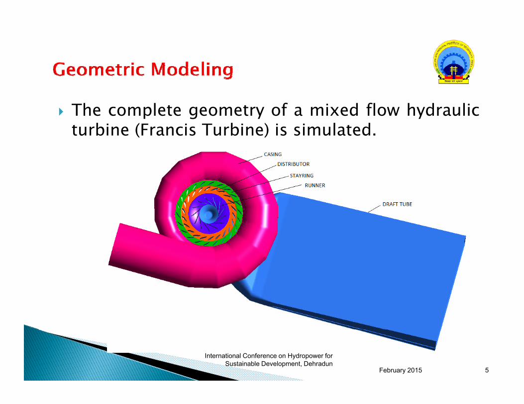
The complete geometry of a mixed flow hydraulict bi (F i T bi ) i i l t dturbine (Francis Turbine) is simulated.
International Conference on Hydropower for Sustainable Development, Dehradun
February 2015 5

SIMPLE DRAFT TUBE VERICAL SPLITETR IN DIFFUSER ATSIMPLE DRAFT TUBE VERICAL SPLITETR IN DIFFUSER AT DIFFUSER
International Conference on Hydropower for Sustainable
Development, Dehradun
HORIZONTAL SPLITTER IN DIFFUSERFebruary 2015 6
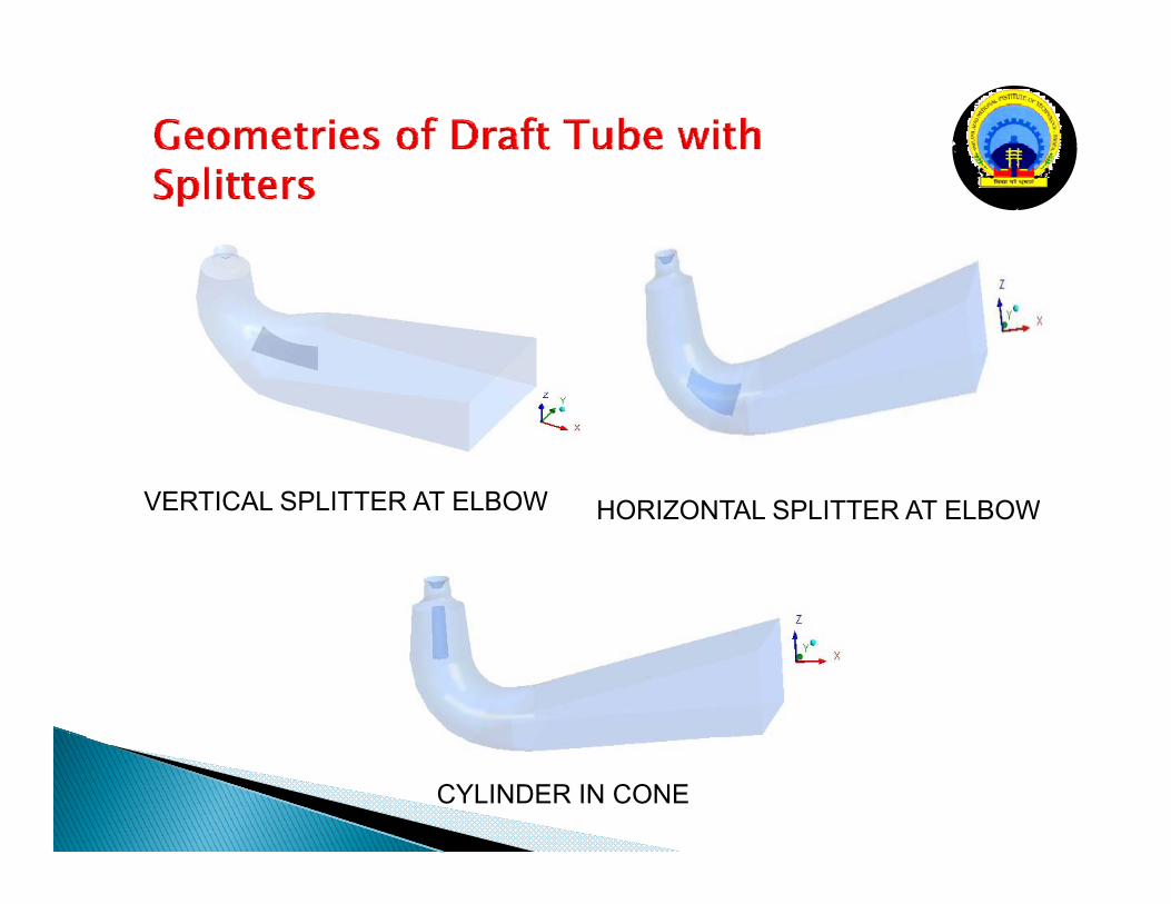
VERTICAL SPLITTER AT ELBOW HORIZONTAL SPLITTER AT ELBOWVERTICAL SPLITTER AT ELBOW HORIZONTAL SPLITTER AT ELBOW
International Conference on Hydropower for Sustainable
Development, DehradunCYLINDER IN CONE
February 2015 7

The flow simulation is performed at rated conditions fora constant guide vane opening of 28º and rotationalspeed of runner was 375 rpm.
Mass flow rate at inlet is specified as 22,200 Kg/sec andkept constant in all simulations.
Pressure at outlet is taken atmospheric
The density and kinematic viscosity of water is taken as The density and kinematic viscosity of water is taken as997 kg/m3 and 0.87 X 10⁻⁶ m2/sec
SST k-ω turbulence model is used.International Conference on Hydropower for
Sustainable Development, Dehradun
February 2015 8

Computation of Hydrodynamic Parameters Computation of Hydrodynamic Parameters
uavdto AQV Uniform averaged velocity at draft tube
outletdto
uavdto A
1
outlet
Mass averaged velocity at draft tube dtoA
mavdto dAvQ
V 21
Mass averaged velocity at draft tube outlet
mavdto
uavdto
VVα Uniformity coefficient
outdind
ld
TPTPH Head loss in draft tube
International Conference on Hydropower for Sustainable Development, Dehradun February 2015 9

Computation Loss and Flow Computation Loss and Flow ParametersParameters
ldH
Parameters...Parameters...
Relative head loss coefficient nHld
22 CCDraft tube recovery (%) 100*)
2( 43
nngHCC
Draft tube efficiency (%) 100*2)(23
24
23
CHgCC n
d
Hydraulic efficiency of turbine(%) 100*30 n
h QHnT
International Conference on Hydropower for Sustainable Development, Dehradun February 2015 10

Comparison of Computed Parameters
Type of Mass Uniformi Draft Eff f H d
Normal average velocity = 1.707 m/s
Type of Draft tube
Mass averaged velocity
attl t
Uniformity coeff.
Draft tube headloss ( )
Head recovery
(m)
Eff. of draft tube( %)
Hydra--ulic
eff. of turbine
Relative head
loss %outlet(m/s)
(m) ( %) tu b e(%)
Simple-draft 1.980 0.862 0.6528 3.643 81.163 91.69 14.54tubeVerticalplate indiffuser
1.956 0.873 0.6800 3.598 80.496 91.08 15.21diffuserHorizontalplate in
2.030 0.841 0.9652 3.363 74.509 91.30 21.38
International Conference on Hydropower for Sustainable Development, Dehradun
diffuser
February 2015 11

Comparison of Computed Parameters...Comparison of Computed Parameters...
Type of Draft tube
Mass averaged velocity at
outlet
Unifor-mity
coeff.
Draft tube headloss
Head reco-very
Eff. of draft tube
( %)
Hydra--ulic
eff. of t bi
Relative headoutlet
(m/s)loss (m)
very(m) turbine
(%)
headloss %
Verticalplate in 2.271 0.752 1.0474 3.308 73.362 91.23 23.22plate inelbow
0.752
Cylinder in 1.971 0.866 1.3056 3.036 64.873 91.16 27.9cone
International Conference on Hydropower for Sustainable Development, Dehradun February 2015 12

60
45505560
)
25303540
ecov
ery
(%)
Simple draft tubeCylinder in coneVertical splitter in diffuserHorizontal splitter in diffuserH i l diff i lb
510152025
Hea
d re Horizontal diffuser in elbow
Vertical splitter in elbow
-505
1 2 3 4 5 6 7 8 9 10 11 12 13
International Conference on Hydropower for Sustainable Development, Dehradun
Sections along stream flow
February 2015 13

The total stream flow length of draft tube fromi l l i di id d i 12 i d hinlet to outlet is divided into 12 sections and thehead recovery between each section is calculatedfor all variants of draft tube.
Most of the head recovery occurs in the draft tubecone. The head recovery has rising trend up to endof cone and then gradually decreases and becomesof cone and then gradually decreases and becomesnearly zero in last 3 sections towards outlet.
In case of horizontal splitter in diffuser, the headrecovery in 5th section is negative indicating thatloss in more than change in kinetic energy and alsothere is large fluctuation in head recovery along thethere is large fluctuation in head recovery along theflow.
International Conference on Hydropower for Sustainable Development, Dehradun February 2015 14

WITHOUT SPLITTER VERTICAL SPLITTER AT DIFFUSERWITHOUT SPLITTER VERTICAL SPLITTER AT DIFFUSER
International Conference on Hydropower for Sustainable Development, Dehradun
HORIZONTAL SPLITTER AT DIFFUSER HORIZONTAL SPLITTER AT ELBOW
February 2015 15

VERTICAL SPLITER AT ELBOW
International Conference on Hydropower for Sustainable Development, Dehradun
CYLINDER AT CONE
February 2015 16
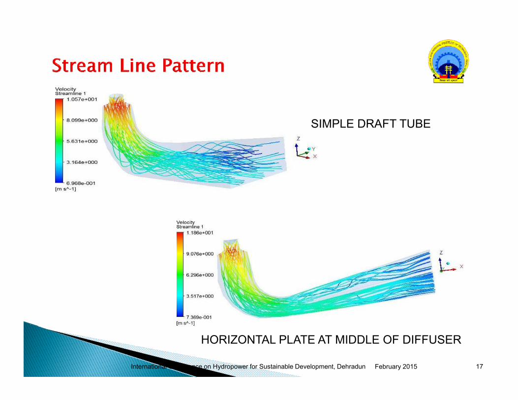
SIMPLE DRAFT TUBESIMPLE DRAFT TUBE
International Conference on Hydropower for Sustainable Development, Dehradun
HORIZONTAL PLATE AT MIDDLE OF DIFFUSER
February 2015 17
The mass average computed velocity from simulationresults at draft tube outlet is higher than normalresults at draft tube outlet is higher than normalaverage velocity and this indicates the concentration offlow to smaller area.
The value of uniformity coefficient has maximum value(0.916) with horizontal splitter in elbow and minimum( ) pvalue (0.752) with vertical splitter in elbow.
It is observed that provision of splitter in draft tube It is observed that provision of splitter in draft tubeincreases the loss in draft tube due to increasedexposed surface area to flow.
International Conference on Hydropower for Sustainable Development, Dehradun February 2015 18

The maximum loss is seen with cylinder in cone The energy recovery is also affected by splitters
and found to be decreasing with minimum recoveryfor cylinder in cone.o cy de co e
The draft tube efficiency is found to be maximum81.163% for simple draft tube and minimum with
li d icylinder in cone. The hydraulic efficiency of turbine is maximum for
simple draft tube and minimum with vertical platep pin diffuser. This is because the velocity head is4.50m at exit of runner which is only 4.73% of thenet head 95m of turbinenet head 95m of turbine.
International Conference on Hydropower for Sustainable Development, Dehradun February 2015 19
It is observed that Flow behavior and performance of drafttube is significantly affected due to splitters at variousg y plocations.
Efficiencies of both draft tube and turbine are found todecrease due splitters and hence there is no advantage ofdecrease due splitters and hence there is no advantage ofsplitter at rated condition.
The uniformity of flow at draft tube outlet is found to bei d i d f b i h h i l li i lbimproved in draft tube with horizontal splitter in elbow.
The most of head recovery occurs in draft tube cone.
The splitter may improve the flow behaviour and performanceof draft tube at part load operation of turbine where largeamount of whirl comes out of runner but location of splitter isto be found again by simulationto be found again by simulation.
International Conference on Hydropower for Sustainable Development, Dehradun February 2015 20