210g/210g lc - john deere 210g lc net rated power 119 kw (159 hp) ... double-seal swing bearing...
TRANSCRIPT

210G/210G LC21 562–22 910 kg (47,494–50,463 lb.) Operating Weight

2
3
Cover all the angles.Heavier and stronger than their popular predecessors, the 210G and 210G LC are also more productive. So, whether you use them to excavate footings, load trucks, set stone, place pipe, or whatever, you’ll get more done per gallon of fuel. What’s more, they’re loaded with customer-inspired refinements such as more comfortable and spacious cabs. Enhanced LCD monitors with simplified navigation that lets an operator easily dial-in a wealth of machine info and functionality. Exceptional power, smoothness, and operating ease — the highly 210G and 210G LC cover all the angles so you can, too.

Both the standard-undercarriage 210G and long-undercarriage 210G LC pack plenty of ability into highly versatile and easy-to-transport packages.
Highly efficient hydraulically driven fans run only as fast as needed, reducing noise, fuel consumption, and operating costs. Reversing option automatically back-blows cooler cores to keep them clean.
With John Deere WorkSight™, JDLink™ monitoring provides real-time machine utilization and health data, plus location information. Machine-health prognostics proactively suggest maintenance to correct problems early before they turn into costly downtime. And remote diagnostics and programming enable your dealer to read diagnostic codes, and record performance data without a trip to the jobsite. It’s the most comprehensive, easy-to-use suite of technology available for increasing uptime and productivity while lowering operating costs. And it’s only available from John Deere.
210G 210G LC
Net rated power 119 kW (159 hp) 119 kW (159 hp)Operating weight 21 562 kg (47,494 lb.) 22 910 kg (50,463 lb.)Maximum digging depth 6.68 m (21 ft. 11 in.) 6.68 m (21 ft. 11 in.)Arm digging force 114 kN (25,543 lb.) 114 kN (25,543 lb.)Bucket digging force 156 kN (35,138 lb.) 156 kN (35,138 lb.)

Additional hydraulic capability a necessity? Two factory-installed high-pressure, high-flow auxiliary packages enable you to meet the need.
Changing hydraulic flow is pushbutton easy right from the seat. Accommodates a wide assortment of attachment needs.
Choose from a variety of track widths, arm lengths, buckets, and other options.
Powerwise III perfectly balances engine performance and hydraulic flow for predictable operation. Three productivity modes allow you to choose the digging style that fits the job. High productivity delivers more power and faster hydraulic response to move more material. Power maximizes fuel economy while balancing horsepower and speed for normal operation. Economy helps conserve fuel as it reduces top speed.
4
5
Unearth more work. With more arm digging force, bucket breakout force, and lift capacity, 210G and 210G LC are impressive performers. But even with all of their extra muscle, their no-compromise Powerwise™ III hydraulic management system yields the fuel efficiency, pinpoint metering, and smooth-as-silk low-effort control that have become trademarks of our excavators. And if you’re looking to put even more work within reach, add any of the many options and attachments that increase machine capability and expand your profit potential.

1 2 3
1. For work that requires extra finesse, short-throw low-effort controls, unmatched metering, and smooth multi-function operation give you the precision you need.
2. Generous hydraulic flow and ample swing torque help speed cycles, so you can keep trucks rolling and excavate efficiently.
3. When the digging gets tough, simply press the power-boost button on the right-hand control and muscle through.

Get unsurpassed operating ease.Now it’s easier than ever for your operators to be even more producitve. The refined monitor employs a rotary control that makes it quick and easy to tap into an abundance of performance and convenience functions and features. Operators will also appreciate the comfortable fabric-covered high-back seat and increased legroom in the spacious, well-appointed cab. As always, unsurpassed all-round visibility, low-effort joysticks, a highly efficient HVAC system, and numerous other amenities provide everything your operators need to do their best work.
6
7

With large self-cleaning steps and wide entryways, getting in and out of an excavator has never been easier.
Spacious cab is comfortable and noticeably quiet. Silicone-filled mounts effectively isolate operators from noise and vibration.
We’ve got your back with a sculpted mechanical-suspension high-back seat. Seat has 318 mm (12½ in.) of travel, sliding together or independent of the joystick console. So it won’t cramp an operator’s style. For even more support and comfort, opt for the air-suspension heated seat.
Ergonomically correct short-throw pilot levers provide smooth, predictable fingertip control with less movement or effort. Push buttons in the right lever allow fingertip control of auxiliary hydraulic flow for operating attachments.
No shortage of storage in here. There’s a place for a cooler, cup holders, and even a hot/cold box that keeps beverages at just the right temperature.
Available boom and cab lights illuminate the way when your workday extends beyond daylight hours (left-side boom light is standard).
1. Multi-language LCD monitor and rotary dial provide intuitive access to a wealth of information and functions. Just turn and tap to select attachments, access operating info, check maintenance intervals, source diagnostic codes, adjust cab temperature, and tune the radio. Plus much more.
2. Wide expanse of front and side glass, narrow front cab posts, large overhead glass, and numerous mirrors provide virtually unobstructed all-around visibility. If you need to see more, choose the optional camera that displays the action behind on the monitor.
3. Automatic, high-velocity bi-level climate-control system with automotive-style adjustable louvers helps keep the glass clear and the cab comfortable.
1
2
3

1
8
9
Nothing runs like a Deere, because nothing is built like one. Unlike some excavators that scream for attention, the hydraulically driven-on-demand fans in our G-Series run only as fast as needed. For reduced noise and fuel consumption. Their highly efficient cooling systems keep things running cool, even in high-trash environments and high altitudes. You’ll also continue to profit from traditional durability-enhancing “extras” such as tungsten-carbide thermal-coated arm surfaces, oil-impregnated bushings, and welded-boom bulkheads. For maximum uptime and long-term durability. When you know how they’re built, you’ll run a Deere.
1. Reinforced D-channel side frames provide maximum cab and component protection.

2 3 4
Reinforced resin thrust plates, grooved bushings, and thermal-coated bucket joints increase arm and boom lube intervals to 500 hours.
Oil-impregnated bushings enhance durability and extend grease intervals to 500 hours for the arm-and-boom joint and 100 hours for the bucket joint.
Tungsten-carbide coating creates an extremely wear-resistant surface to protect the all-important bucket-to-arm joint.
A John Deere exclusive, three welded bulkheads within the boom resist torsional stress for unsurpassed durability. Booms, arms, and mainframes are so tough, they’re warranted for three years or 10,000 hours.
Thick-plate single-sheet mainframe, box-section track frames, and industry-exclusive double-seal swing bearing deliver rock- solid durability.
Wet-sleeve cylinder liners, mono-steel pistons, and large-diameter connecting rods ensure long-term engine durability.
2. With large idlers, rollers, and strutted links, the sealed and lubricated undercarriage delivers long and reliable performance.
3. Highly efficient, heavy-duty cooling system keeps things cool, even in tough environments or high altitudes.
4. TK-Series bucket teeth are engineered for maximum strength and impact absorption. Hammer-free installation and removal simplifies changes, mini- mizes downtime.

1 2 3
Uncover all the ways we keep costs down. Like all John Deere machines, the G-Series Excavators are loaded with features that make them hassle-free to service and low-cost to maintain. Large, easy-to-open doors and easy-access service points make quick work of the daily routine. Remote-mounted vertical oil and fuel filters and extended engine and hydraulic oil-change intervals minimize maintenance, too. Plus the Machine Information Center (MIC), state-of-the-art LCD color monitor, and fluid-sample ports help you make timely decisions about machine upkeep — and manage uptime and costs.
Centralized lubrication banks place difficult-to-lube zerks within easy reach. They make greasing less messy and time consuming, too.
Machine Information Center captures and stores vital machine performance and utilization data to help improve uptime.
Fluid-level sight gauges are conveniently located and can be checked at a glance.
Convenient color-coded lubrication and maintenance chart helps ensure that nothing gets overlooked.
Auto-idle automatically reduces engine speed when hydraulics aren’t in use. Auto-shutdown further preserves precious fuel.
Optional reversing fan back-blows cooler cores to reduce debris buildup. It’s a welcome addition that helps increase uptime.
Large fuel tanks and 500- and 5,000-hour engine and hydraulic oil-service intervals decrease downtime for routine maintenance.
10
11

6
1. Easy-to-read LCD monitor tracks scheduled maintenance intervals and issues reminders. Should a problem arise, it provides diagnostic information to help decrease downtime.
2. Convenient fluid-sample and diagnostic test ports help speed preventative maintenance and defeat downtime.
3. Vertical spin-on fuel and engine oil filters are positioned in the right rear compartment for simplified ground-level servicing.
4. Fresh-air cab filter is quickly serviced from outside the cab where it’s more likely to get done.
5. Easy-to-reach dipstick and nearby coolant reservoir make daily checks and/or additions quick and easy.
6. Perforations in the side shields act as a “first filter.” Anything that passes through will also clear the 10-fin-per-inch cooler cores.
4 5

210G / 210G LC
12
13
Engine 210G / 210G LCManufacturer and Model John Deere PowerTech™ Plus 6.8 L John Deere PowerTech™ 6.8 LNon-Road Emission Standard EPA Tier 3/EU Stage IIIA EPA Tier 2/EU Stage IINet Rated Power (ISO 9249) 119 kW (159 hp) at 2,000 rpm 119 kW (159 hp) at 2,000 rpmCylinders 6 6Displacement 6.8 L (415 cu. in.) 6.8 L (415 cu. in.)Off-Level Capacity 70% (35 deg.) 70% (35 deg.)Aspiration Turbocharged, air-to-air charge-air
coolerTurbocharged, air-to-air charge-air cooler
CoolingCool-on-demand hydraulic-driven, suction-type fan with remote-mounted drivePowertrain2-speed propel with automatic shiftMaximum Travel Speed Low 3.5 km/h (2.2 mph) High 5.5 km/h (3.4 mph)Drawbar Pull 20 693 kg (45,620 lb.)HydraulicsOpen center, load sensingMain Pumps 2 variable-displacement axial-piston pumps Maximum Rated Flow 212 L/m (56 gpm) x 2Pilot Pump One gear Maximum Rated Flow 30.0 L/m (7.9 gpm) Pressure Setting 3999 kPa (580 psi)System Operating Pressure Circuits Implement 34 336 kPa (4,980 psi) Travel 34 336 kPa (4,980 psi) Swing 34 336 kPa (4,980 psi) Power Boost 38 000 kPa (5,511 psi)Controls Pilot levers, short stroke, low-effort hydraulic pilot controls with shutoff leverCylinders
Bore Rod Diameter StrokeBoom (2) 120 mm (4.72 in.) 85 mm (3.35 in.) 1260 mm (49.61 in.)Arm (1) 135 mm (5.31 in.) 95 mm (3.74 in.) 1475 mm (58.07 in.)Bucket (1) 115 mm (4.53 in.) 80 mm (3.15 in.) 1060 mm (41.73 in.)ElectricalNumber of Batteries (12 volt) 2Battery Capacity 1,400 CCAAlternator Rating 100 ampWork Lights 2 halogen (one mounted on boom, one on frame)Undercarriage 210G 210G LCRollers (each side) Carrier 2 2 Track 7 8Shoes, Triple Semi-Grousers (each side) 46 49Track Adjustment Hydraulic Hydraulic Guides Center Center Chain Sealed and lubricated Sealed and lubricatedGround PressureTriple Semi-Grouser Shoes 600 mm (24 in.) 45.0 kPa (6.53 psi) 47.9 kPa (6.95 psi) 700 mm (28 in.) 39.0 kPa (5.66 psi) 41.7 kPa (6.05 psi) 800 mm (32 in.) 34.0 kPa (4.93 psi) 36.9 kPa (5.35 psi)

Swing Mechanism 210G / 210G LCSpeed 13.3 rpmTorque 68 900 Nm (50,662 lb.-ft.)ServiceabilityRefill Capacities Fuel Tank 403 L (106.5 gal.) Cooling System 30.5 L (32.2 qt.) Engine Oil with Filter 20.8 L (22 qt.) Hydraulic Tank 135 L (35.7 gal.) Hydraulic System 240 L (63.4 gal.) Gearbox Swing 6.2 L (6.6 qt.) Propel (each) 7.8 L (8.2 qt.) Pump Drive 1.0 L (1.1 qt.)Operating Weights 210G 210G LCWith full fuel tank; 79-kg (175 lb.) operator; 1065-mm (42 in.), 0.91-m3 (1.19 cu. yd.), 886-kg (1,951 lb.) general-purpose bucket; and 4250-kg (9,370 lb.) counterweightOperating Weight 2.91-m (9 ft. 7 in.) Arm and 800-mm (32 in.) Triple Semi-Grouser Shoes
22 309 kg (49,139 lb.) 22 910 kg (50,463 lb.)
2.42-m (7 ft. 11 in.) Arm and 600-mm (24 in.) Triple Semi-Grouser Shoes
21 562 kg (47,494 lb.) 22 163 kg (48,817 lb.)
Component Weights Undercarriage with Triple Semi- Grouser Shoes 600 mm (24 in.) 6752 kg (14,873 lb.) 7353 kg (16,196 lb.) 700 mm (28 in.) 7143 kg (15,733 lb.) 7743 kg (17,055 lb.) 800 mm (32 in.) 7437 kg (16,381 lb.) 8038 kg (17,705 lb.) One-Piece Boom (with arm cylinder) 1732 kg (3,815 lb.) 1732 kg (3,815 lb.) Arm with Bucket Cylinder and Linkage 2.22 m (7 ft. 3 in.) 928 kg (2,044 lb.) 928 kg (2,044 lb.) 2.91 m (9 ft. 7 in.) 990 kg (2,181 lb.) 990 kg (2,181 lb.) Boom-Lift Cylinders (2), Total Weight 341 kg (751 lb.) 341 kg (751 lb.)
CEN
TERL
INE
OF
SWIN
G
GROUND LINE
E
C D
B B’
A’A
F
Operating Dimensions 210G / 210G LCArm Length 2.42 m (7 ft. 11 in.) 2.91m (9 ft.7 in.) Arm Digging Force SAE 133 kN (29,959 lb.) 110 kN (24,773 lb.) ISO 139 kN (31,355 lb.) 114 kN (25,543 lb.) Bucket Digging Force SAE 142 kN (31,865 lb.) 142 kN (31,865 lb.) ISO 156 kN (35,138 lb.) 156 kN (35,138 lb.)A Maximum Reach 9.43 m (30 ft. 11 in.) 9.92 m (32 ft. 7 in.)A| Maximum Reach at Ground Level 9.25 m (30 ft. 4 in.) 9.75 m (32 ft. 0 in.)B Maximum Digging Depth 6.18 m (20 ft. 3 in.) 6.68 m (21 ft. 11 in.)B| Maximum Digging Depth at 2.44-m
(8 ft. 0 in.) Flat Bottom5.95 m (19 ft. 6 in.) 6.50 m (21 ft. 4 in.)
C Maximum Cutting Height 9.67 m (31 ft. 9 in.) 10.04 m (32 ft. 11 in.)D Maximum Dumping Height 6.83 m (22 ft. 5 in.) 7.18 m (23 ft. 7 in.)E Minimum Swing Radius 3.28 m (10 ft. 9 in.) 3.18 m (10 ft. 5 in.)F Maximum Vertical Wall 5.30 m (17 ft. 5 in.) 5.99 m (19 ft. 8 in)
14
15
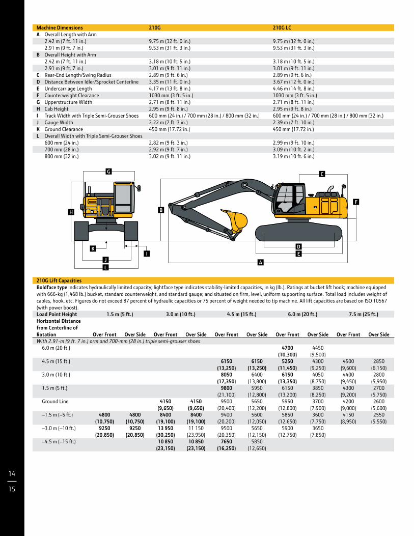
Machine Dimensions 210G 210G LCA Overall Length with Arm
2.42 m (7 ft. 11 in.) 9.75 m (32 ft. 0 in.) 9.75 m (32 ft. 0 in.)2.91 m (9 ft. 7 in.) 9.53 m (31 ft. 3 in.) 9.53 m (31 ft. 3 in.)
B Overall Height with Arm2.42 m (7 ft. 11 in.) 3.18 m (10 ft. 5 in.) 3.18 m (10 ft. 5 in.)2.91 m (9 ft. 7 in.) 3.01 m (9 ft. 11 in.) 3.01 m (9 ft. 11 in.)
C Rear-End Length/Swing Radius 2.89 m (9 ft. 6 in.) 2.89 m (9 ft. 6 in.)D Distance Between Idler/Sprocket Centerline 3.35 m (11 ft. 0 in.) 3.67 m (12 ft. 0 in.)E Undercarriage Length 4.17 m (13 ft. 8 in.) 4.46 m (14 ft. 8 in.)F Counterweight Clearance 1030 mm (3 ft. 5 in.) 1030 mm (3 ft. 5 in.)G Upperstructure Width 2.71 m (8 ft. 11 in.) 2.71 m (8 ft. 11 in.)H Cab Height 2.95 m (9 ft. 8 in.) 2.95 m (9 ft. 8 in.)I Track Width with Triple Semi-Grouser Shoes 600 mm (24 in.) / 700 mm (28 in.) / 800 mm (32 in.) 600 mm (24 in.) / 700 mm (28 in.) / 800 mm (32 in.)J Gauge Width 2.22 m (7 ft. 3 in.) 2.39 m (7 ft. 10 in.)K Ground Clearance 450 mm (17.72 in.) 450 mm (17.72 in.)L Overall Width with Triple Semi-Grouser Shoes
600 mm (24 in.) 2.82 m (9 ft. 3 in.) 2.99 m (9 ft. 10 in.)700 mm (28 in.) 2.92 m (9 ft. 7 in.) 3.09 m (10 ft. 2 in.)800 mm (32 in.) 3.02 m (9 ft. 11 in.) 3.19 m (10 ft. 6 in.)
H
IK
CG
JL
BF
DE
A
210G Lift CapacitiesBoldface type indicates hydraulically limited capacity; lightface type indicates stability-limited capacities, in kg (lb.). Ratings at bucket lift hook; machine equipped with 666-kg (1,468 lb.) bucket, standard counterweight, and standard gauge; and situated on firm, level, uniform supporting surface. Total load includes weight of cables, hook, etc. Figures do not exceed 87 percent of hydraulic capacities or 75 percent of weight needed to tip machine. All lift capacities are based on ISO 10567 (with power boost).Load Point Height 1.5 m (5 ft.) 3.0 m (10 ft.) 4.5 m (15 ft.) 6.0 m (20 ft.) 7.5 m (25 ft.)Horizontal Distance from Centerline of Rotation
Over Front
Over Side
Over Front
Over Side
Over Front
Over Side
Over Front
Over Side
Over Front
Over SideWith 2.91-m (9 ft. 7 in.) arm and 700-mm (28 in.) triple semi-grouser shoes 6.0 m (20 ft.) 4700
(10,300) 4450
(9,500) 4.5 m (15 ft.) 6150
(13,250)6150
(13,250)5250
(11,450)4300
(9,250)4500
(9,600)2850
(6,150) 3.0 m (10 ft.) 8050
(17,350)6400
(13,800)6150
(13,350)4050
(8,750)4400
(9,450)2800
(5,950) 1.5 m (5 ft.) 9800
(21,100)5950
(12,800)6150
(13,200)3850
(8,250)4300
(9,200)2700
(5,750) Ground Line 4150
(9,650)4150
(9,650)9500
(20,400)5650
(12,200)5950
(12,800)3700
(7,900)4200
(9,000)2600
(5,600) –1.5 m (–5 ft.) 4800
(10,750)4800
(10,750)8400
(19,100)8400
(19,100)9400
(20,200)5600
(12,050)5850
(12,650)3600
(7,750)4150
(8,950)2550
(5,550) –3.0 m (–10 ft.) 9250
(20,850)9250
(20,850)13 950
(30,250)11 150
(23,950)9500
(20,350)5650
(12,150)5900
(12,750)3650
(7,850) –4.5 m (–15 ft.) 10 850
(23,150)10 850
(23,150)7650
(16,250)5850
(12,650)

Buckets 210G / 210G LCA full line of buckets is offered to meet a wide variety of applications. Digging forces are with power boost. Buckets are equipped with John Deere TK-Series Bucket Teeth standard. Replaceable cutting edges and a variety of teeth are available through John Deere Parts. Optional side cutters add 150 mm (6 in.) to bucket widths. Capacities are SAE heaped ratings. Type Bucket
Bucket Width
Bucket Capacity
Bucket Weight
Bucket Dig Force
Arm Dig Force 2.42 m (7 ft. 11 in.)
Arm Dig Force 2.91 m (9 ft. 7 in.)
Bucket Tip Radius
Number of Teeth
mm in. m3 cu. yd. kg lb. kN lb. kN lb. kN lb. mm in.Heavy Duty 915 36 0.69 0.90 708 1,559 135.9 30,554 130.2 29,271 107.1 24,071 1463 57.61 5
1065 42 0.83 1.09 786 1,731 135.9 30,554 130.2 29,271 107.1 24,071 1463 57.61 51220 48 0.99 1.29 872 1,921 135.9 30,554 130.2 29,271 107.1 24,071 1463 57.61 6
Heavy Duty High Capacity
610
24
0.43
0.56
646
1,424
135.0
30,349
129.9
29,197
106.8
24,016
1473
58.00
4
760 30 0.58 0.76 723 1,593 135.0 30,349 129.9 29,197 106.8 24,016 1473 58.00 4 915 36 0.74 0.97 809 1,782 135.0 30,349 129.9 29,197 106.8 24,016 1473 58.00 51065 42 0.91 1.19 886 1,951 135.0 30,349 129.9 29,197 106.8 24,016 1473 58.00 51219 48 1.18 1.54 1,112 2,450 157.2 35,332 132.7 29,840 109.8 24,685 1479 58.22 6
Bucket Selection Guide*
2.3(3.0)
1.5(2.0)
2,000 2,200 2,600 3,200lb./cu. yd.kg/m3
1,600 3,400
0.8(1.0)
1.0(1.5)
1.9(2.5)
2.7(3.5)
1,200 1,400 1,800 2,400 2,800 3,000 3,600
1300700 800 900 1000 1100 1200 20001400 1500 1600 1700 1800 1900 2100
Wet
Pea
t
Tops
oil
Coal
Calic
he
Shal
e
Dry
Sand
Dry
Clay
Lim
esto
ne
Wet
Ear
th
Wet
Cla
y, Gr
anite
Moi
st S
and
Wet
San
d
Wet
San
d, G
rave
l*Contact your John Deere dealer for optimum bucket and attachment selections. These recommendations are for general conditions and average use. Does not include
optional equipment such as thumbs or couplers. Larger buckets may be possible when using light materials, for flat and level operations, less compacted materials, andvolume loading applications such as mass-excavation applications in ideal conditions. Smaller buckets are recommended for adverse conditions such as off-level appli-cations, rocks, and uneven surfaces. Bucket capacity indicated is SAE heaped.
BUCK
ET S
IZE
m (
cu. y
d.)
3
Deere 2.42-m (7 ft. 11 in.) Arm
Deere 2.91-m (9 ft. 7 in.) Arm

16
17
210G LC Lift CapacitiesBoldface type indicates hydraulically limited capacity; lightface type indicates stability-limited capacities, in kg (lb.). Ratings at bucket lift hook; machine equipped with 666-kg (1,468 lb.) bucket, standard counterweight, and standard gauge; and situated on firm, level, uniform supporting surface. Total load includes weight of cables, hook, etc. Figures do not exceed 87 percent of hydraulic capacities or 75 percent of weight needed to tip machine. All lift capacities are based on ISO 10567 (with power boost).Load Point Height 1.5 m (5 ft.) 3.0 m (10 ft.) 4.5 m (15 ft.) 6.0 m (20 ft.) 7.5 m (25 ft.)Horizontal Distance from Centerline of Rotation
Over Front
Over Side
Over Front
Over Side
Over Front
Over Side
Over Front
Over Side
Over Front
Over SideWith 2.42-m (7 ft. 11 in.) arm and 800-mm (32 in.) triple semi-grouser shoes 6.0 m (20 ft.) 5200
(11,450)4950
(10,600) 4.5 m (15 ft.)
(20,650)
(20,650)6850
(14,800)6850
(14,800)5750
(12,450)4850
(10,400) 3.0 m (10 ft.) 8750
(18,800)7200
(15,550)6550
(14,150)4600
(9,950)5150
(11,000)3200
(6,850) 1.5 m (5 ft.) 10 250
(22,100)6750
(14,550)7200
(15,450)4400
(9,500)5050
(10,800)3100
(6,700) Ground Line 10 750
(23,300)6550
(14,150)7050
(15,100)4250
(9,200)4950
(10,650)3050
(6,550) –1.5 m (–5 ft.) 9150
(21,050)9150
(21,050)10 450
(22,600)6550
(14,100)7000
(15,050)4250
(9,100) –3.0 m (–10 ft.) 12 800
(27,750)12 800
(27,750)9250
(20,000)6650
(14,300)6650
(14,200)4300
(9,300) –4.5 m (–15 ft.) 6400
(13,250)6400
(13,250)
210G Lift Capacities (continued)Boldface type indicates hydraulically limited capacity; lightface type indicates stability-limited capacities, in kg (lb.). Ratings at bucket lift hook; machine equipped with 666-kg (1,468 lb.) bucket, standard counterweight, and standard gauge; and situated on firm, level, uniform supporting surface. Total load includes weight of cables, hook, etc. Figures do not exceed 87 percent of hydraulic capacities or 75 percent of weight needed to tip machine. All lift capacities are based on ISO 10567 (with power boost).Load Point Height 1.5 m (5 ft.) 3.0 m (10 ft.) 4.5 m (15 ft.) 6.0 m (20 ft.) 7.5 m (25 ft.)Horizontal Distance from Centerline of Rotation
Over Front
Over Side
Over Front
Over Side
Over Front
Over Side
Over Front
Over Side
Over Front
Over SideWith 2.91-m (9 ft. 7 in.) arm and 800-mm (32 in.) triple semi-grouser shoes 6.0 m (20 ft.) 4700
(10,300)4500
(9,650) 4.5 m (15 ft.) 6150
(13,250)6150
(13,250)5250
(11,450)4350
(9,400)4600
(9,800)2950
(6,250) 3.0 m (10 ft.) 8050
(17,350)6500
(14,050)6150
(13,350)4150
(8,950)4500
(9,650)2850
(6,100) 1.5 m (5 ft.) 9800
(21,100)6050
(13,000)6250
(13,450)3900
(8,450)4350
(9,400)2750
(5,850) Ground Line 4150
(9,650)4150
(9,650)9700
(20,800)5750
(12,450)6050
(13,050)3750
(8,050)4300
(9,200)2650
(5,700) –1.5 m (–5 ft.) 4800
(10,750)4800
(10,750)8400
(19,100)8400
(19,100)9600
(20,600)5700
(12,250)6000
(12,900)3700
(7,900)4250
(9,150)2650
(5,650) –3.0 m (–10 ft.) 9250
(20,850)9250
(20,850)13 950
(30,250)11 350
(24,350)9650
(20,750)5750
(12,400)6050
(13,000)3700
(8,000) –4.5 m (–15 ft.) 10 850
(23,150)10 850
(23,150)7650
(16,250)5950
(12,850)

210G LC Lift Capacities (continued)Boldface type indicates hydraulically limited capacity; lightface type indicates stability-limited capacities, in kg (lb.). Ratings at bucket lift hook; machine equipped with 666-kg (1,468 lb.) bucket, standard counterweight, and standard gauge; and situated on firm, level, uniform supporting surface. Total load includes weight of cables, hook, etc. Figures do not exceed 87 percent of hydraulic capacities or 75 percent of weight needed to tip machine. All lift capacities are based on ISO 10567 (with power boost).Load Point Height 1.5 m (5 ft.) 3.0 m (10 ft.) 4.5 m (15 ft.) 6.0 m (20 ft.) 7.5 m (25 ft.)Horizontal Distance from Centerline of Rotation
Over Front
Over Side
Over Front
Over Side
Over Front
Over Side
Over Front
Over Side
Over Front
Over SideWith 2.91-m (9 ft. 7 in.) arm and 600-mm (24 in.) triple semi-grouser shoes 6.0 m (20 ft.) 4700
(10,300)4700
(10,300) 4.5 m (15 ft.) 6150
(13,250)6150
(13,250)5250
(11,450)4700
(10,150)4850
(10,650)3150
(6,750) 3.0 m (10 ft.) 8050
(17,350)7100
(15,250)6150
(13,350)4500
(9,650)4950
(10,600)3100
(6,600) 1.5 m (5 ft.) 9800
(21,100)6600
(14,200)6900
(14,900)4250
(9,150)4800
(10,350)2950
(6,400) Ground Line 4150
(9,650)4150
(9,650)10 650
(23,050)6300
(13,600)6750
(14,500)4100
(8,800)4700
(10,150)2900
(6,200) –1.5 m (–5 ft.) 4800
(10,750)4800
(10,750)8400
(19,100)8400
(19,100)10 600
(23,000)6250
(13,400)6650
(14,300)4000
(8,600)4700
(10,100)2850
(6,150) –3.0 m (–10 ft.) 9250
(20,850)9250
(20,850)13 950
(30,250)12 700
(27,150)9750
(21,050)6300
(13,550)6700
(14,400)4050
(8,700) –4.5 m (–15 ft.) 10 850
(23,150)10 850
(23,150)7650
(16,250)6500
(14,050)With 2.91-m (9 ft. 7 in.) arm and 700-mm (28 in.) triple semi-grouser shoes 6.0 m (20 ft.) 4700
(10,300)4700
(10,300) 4.5 m (15 ft.) 6150
(13,250)6150
(13,250)5250
(11,450)4800
(10,350)4850
(10,650)3250
(6,950) 3.0 m (10 ft.) 8050
(17,350)7250
(15,600)6150
(13,350)4600
(9,850)5050
(10,850)3150
(6,750) 1.5 m (5 ft.) 9800
(21,100)6750
(14,500)7050
(15,200)4350
(9,350)4950
(10,600)3050
(6,550) Ground Line 4150
(9,650)4150
(9,650)10 650
(23,050)6450
(13,900)6900
(14,850)4200
(9,000)4850
(10,400)2950
(6,350) –1.5 m (–5 ft.) 4800
(10,750)4800
(10,750)8400
(19,100)8400
(19,100)10 600
(23,000)6400
(13,750)6800
(14,650)4100
(8,850)4800
(10,350)2950
(6,350) –3.0 m (–10 ft.) 9250
(20,850)9250
(20,850)13 950
(30,250)12 950
(27,750)9750
(21,050)6450
(13,900)6850
(14,750)4150
(8,950) –4.5 m (–15 ft.) 10 850
(23,150)10 850
(23,150)7650
(16,250)6650
(14,350)With 2.91-m (9 ft. 7 in.) arm and 800-mm (32 in.) triple semi-grouser shoes 6.0 m (20 ft.) 4700
(10,300)4700
(10,300) 4.5 m (15 ft.) 6150
(13,250)6150
(13,250)5250
(11,450)4900
(10,500)4850
(10,650)3300
(7,050) 3.0 m (10 ft.) 8050
(17,350)7350
(15,850)6150
(13,350)4650
(10,050)5150
(11,050)3200
(6,900) 1.5 m (5 ft.) 9800
(21,100)6850
(14,750)7050
(15,200)4450
(9,550)5050
(10,800)3100
(6,700) Ground Line 4150
(9,650)4150
(9,650)10 650
(23,050)6600
(14,150)7050
(15,100)4250
(9,150)4950
(10,650)3000
(6,500) –1.5 m (–5 ft.) 4800
(10,750)4800
(10,750)8400
(19,100)8400
(19,100)10 600
(23,000)6500
(14,000)6950
(14,950)4200
(9,000)4900
(10,600)3000
(6,450) –3.0 m (–10 ft.) 9250
(20,850)9250
(20,850)13 950
(30,250)13 200
(28,200)9750
(21,050)6550
(14,150)7000
(15,050)4200
(9,100) –4.5 m (–15 ft.) 10 850
(23,150)10 850
(23,150)7650
(16,250)6800
(14,600)

JohnDeere.com
Key: l Standard s Optional or special See your John Deere dealer for further information.
Additional equipment
DKAX210G Litho in U.S.A. (15-01)
Net engine power is with standard equipment including air cleaner, exhaust system, alternator, and cooling fan, at test conditions specified per ISO 9249. No derating is required up to 3050-m (10,000 ft.) altitude. Specifications and design subject to change without notice. Wherever applicable, specifications are in accordance with SAE standards. Except where otherwise noted, these specifications are based on units with 1065-mm (42 in.), 0.91-m3 (1.19 cu. yd.),
886-kg (1,951 lb.) general-purpose buckets; 2.91-m (9 ft. 7 in.) arms; 4250-kg (9,370 lb.) counterweights; 800-mm (32 in.) triple semi-grouser shoes; full fueltanks; and 79-kg (175 lb.) operators.
210G / 210G LC
Engine
l Auto-idle systeml Automatic belt-tension devicel Batteries (2 – 12 volt)l Coolant recovery tankl Dual-element dry-type air filterl Electronic engine controll Enclosed fan guard (conforms to SAE J1308)l Engine coolant to –37 deg. C (–34 deg. F)l Fuel filter with water separatorl Full-flow oil filterl Turbocharger with charge air coolerl Cool-on-demand hydraulic-driven fanl 500-hour engine-oil-change intervall 70% (35 deg.) off-level capabilityl Engine-oil-sampling valvel Programmable auto shutdowns Chrome exhaust stacks Severe-duty fuel filters Hydraulic fan reversers Engine coolant heater
Hydraulic Systeml Reduced-drift valve for boom down, arm inl Auxiliary hydraulic valve sectionl Spring-applied, hydraulically released
automatic swing brakel Auxiliary hydraulic-flow adjustments
through monitorl Auto power liftl 5,000-hour hydraulic-oil-change intervall Hydraulic-oil-sampling valves Auxiliary hydraulic liness Auxiliary pilot and electric controlss Hydraulic filter restriction indicator kits Load-lowering control devices Single-pedal propel controls Control pattern-change valve
Undercarriagel Planetary drive with axial piston motorsl Propel motor shieldsl Spring-applied, hydraulically released
automatic propel brakel Track guides, front idler and centerl 2-speed propel with automatic shiftl Upper carrier rollers (2)l Sealed and lubricated track chains Triple semi-grouser shoes, 600 mm (24 in.)s Triple semi-grouser shoes, 700 mm (28 in.)s Triple semi-grouser shoes, 800 mm (32 in.)
210G / 210G LC
Upperstructure
l Right-hand, left-hand, and counterweight mirrors
l Vandal locks with ignition key: Cab door / Service doors / Toolbox
l Debris screen in side panell Remote-mounted engine oil and fuel filters
Front Attachmentsl Centralized lubrication systeml Dirt seals on all bucket pinsl Less boom and arml Oil-impregnated bushingsl Reinforced resin thrust platesl Tungsten carbide thermal coating on arm-
to-bucket joints Arm, 2.42 m (7 ft. 11 in.)s Arm, 2.91 m (9 ft. 7 in.)s Attachment quick-couplerss Boom cylinder with plumbing to mainframe
for less boom and arms Buckets: Heavy duty / Heavy-duty high
capacity / Side cutters and teeths Material clamps s Super-long fronts
Operator’s Stationl Meets ISO 12117-2 for ROPSl Adjustable independent-control positions
(levers-to-seat, seat-to-pedals)l AM/FM radiol Auto climate control/air conditioner/
heater/pressurizerl Built-in Operator’s Manual storage com-
partment and manuall Cell-phone power outlet, 12 volt, 60 watt,
5 ampl Coat hookl Deluxe suspension cloth seat with 100-mm
(4 in.) adjustable armrestsl Floor matl Front windshield wiper with intermittent
speedsl Gauges (illuminated): Engine coolant / Fuell Horn, electricl Hour meter, electricl Hydraulic shutoff lever, all controlsl Hydraulic warm-up controll Interior lightl Large cup holder
210G / 210G LC
Operator’s Station (continued)
l Machine Information Center (MIC)l Mode selectors (illuminated): Power modes
(3) / Travel modes (2 with automatic shift) / Work mode (1)
l Multifunction, color LCD monitor with: Diagnostic capability / Multiple-language capabilities / Maintenance tracking / Clock / System monitoring with alarm features: Auto-idle indicator, engine air cleaner restriction indicator light, engine check, engine coolant temperature indicator light with audible alarm, engine oil pressure indicator light with audible alarm, low- alternator-charge indicator light, low-fuel indicator light, fault code alert indicator, fuel-rate display, wiper-mode indicator, work-lights-on indicator, and work-mode indicator
l Motion alarm with cancel switch (conforms to SAE J994)
l Power-boost switch on right console leverl Auxiliary hydraulic control switches in right
console leverl SAE 2-lever control patternl Seat belt, 51 mm (2 in.), retractablel Tinted glassl Transparent tinted overhead hatchl Hot/cold beverage compartments Air-suspension heated seats Hydraulic oil filter restriction indicator lights Protection screens for cab front, rear,
and sides Seat belt, 76 mm (3 in.), non-retractables Window vandal-protection covers
Electricall 100-amp alternatorl Blade-type multi-fused circuitsl Positive-terminal battery coversl JDLink™ wireless communication system
(available in specific countries; see your dealer for details)
s Rearview cameras Cab extension wiring harness
Lightsl Work lights: Halogen / One mounted on
boom / One mounted on frames 2 lights mounted on cab / One mounted
on right side of boom