216.1-97 standard method for determining fire resistance...
TRANSCRIPT
ACI Committee Reports, Guides, Standard Practices, andCommentaries are intended for guidance in planning, design-ing, executing, and inspecting construction. This documentis intended for the use of individuals who are competentto evaluate the significance and limitations of its contentand recommendations and who will accept responsibilityfor the application of the material it contains. The AmericanConcrete Institute disclaims any and all responsibility for thestated principles. The Institute shall not be liable for any lossor damage arising therefrom.Reference to this document shall not be made in contractdocuments. If items found in this document are desired bythe Architect/Engineer to be a part of the contract documents,they shall be restated in mandatory language for incorporationby the Architect/Engineer.
Standard Method for Determining Fire Resistance of Concrete and Masonry
Construction Assemblies
ACI 216.1-97 / TMS 0216.1-97
*Immediate past chairman
James P. HurstChairman
Gene C. Abbate Thomas F. Herrell Mark A. Nunn
Stanley G. Barton Mark Hogan John Perry
Ronald G. Burg Thomas H. Holm Walter Prebis
Donald O. Dusenberry Joel R. Irving John P. Ries
William L. Gamble* Phillip J. Iverson Thomas J. Rowe
Richard G. Gewain T. T. Lie Jeffery F. Speck
Michael P. Gillen Tung D. Lin F. R. Vollert
Tibor Z. Harmathy Howard R. May
FOREWORDFire resistance of building elements is an important consideration in building
design. While structural design considerations for concrete and masonry at
ambient temperature conditions are addressed by ACI 318 and ACI 530/
ASCE 5/TMS 402, respectively, these codes do not consider the impact of fire
on concrete and masonry construction. The standard portion of this docu-
ment contains such design and analytical procedures for determining the fire
resistance of concrete and masonry members and building assemblies. Where
differences occur in specific design requirements between this standard and
the above referenced codes, as in the case of cover protection of steel rein-
forcement, the more stringent of the requirements shall apply.
Keywords: beams (supports); columns (supports); compressive strength;
concrete slabs, fire ratings; fire endurance; fire resistance; fire tests; masonry
walls; modulus of elasticity; prestressed concrete; prestressing steels; rein-
forced concrete; reinforcing steel; structural design; temperature distribution;
thermal properties; walls.
Reported by ACI/TMS Committee 216
CONTENTS Chapter 1—General
1.1—Scope1.2—Alternative methods1.3—Definitions1.4—Notation1.5—Fire resistance determinations
Chapter 2—Concrete2.1—General2.2—Concrete walls, floors and roofs2.3—Concrete cover protection of steel reinforcement2.4—Analytical methods for calculating structural fire
resistance and cover protection of concrete flexuralmembers
2.5—Reinforced concrete columns
Chapter 3—Concrete masonry3.1—General3.2—Equivalent thickness3.3—Concrete masonry wall assemblies3.4—Reinforced concrete masonry columns3.5—Concrete masonry lintels3.6—Structural steel columns protected by concrete masonry
ACI 216.1-97 became effective September 1, 1997.Copyright 1997, American Concrete Institute.All rights reserved including rights of reproduction and use in any form or by any
means, including the making of copies by any photo process, or by electronic ormechanical device, printed, written, or oral, or recording for sound or visual reproduc-tion or for use in any knowledge or retrieval system or device, unless permission inwriting is obtained from the copyright proprietors.
1
N
ACI STA216.1-2Chapter 4—Clay brick and tile masonry4.1—General4.2—Equivalent thickness4.3—Clay brick and tile masonry wall assemblies4.4—Reinforced clay masonry columns4.5—Reinforced clay masonry lintels4.6—Expansion or contraction joints4.7—Structural steel columns protected by clay masonry
Chapter 5—Effects of finish materials on fire resistance
5.1—General5.2—Calculation procedure5.3—Installation of finishes
Chapter 6—References
Appendices
CHAPTER 1—GENERAL1.1—Scope
This standard describes acceptable methods for determin-ing the fire resistance of concrete and masonry assembliesand structural elements including walls, floor and roof slabs,beams, columns, lintels, and masonry fire protection forstructural steel columns. These methods shall be used for de-sign and analytical purposes and shall be based upon the fireexposure and applicable end-point criteria of ASTM E 119.This standard does not apply to composite metal deck flooror roof assemblies.
1.2—Alternative methodsMethods other than those presented in this standard shall
be permitted for use in assessing the fire resistance of con-crete and masonry building assemblies and structural ele-ments, if the methods are based upon the fire exposure andapplicable end-point criteria specified in ASTM E 119.
1.3—DefinitionsThe following definitions apply for this standard:Approved—Approved by the Building Official responsi-
ble for enforcing the legally adopted building code of whichthis standard is a part, or approved by some other authorityhaving jurisdiction.
Barrier element—A building member that performs as abarrier to the spread of fire (for example, walls, floors, androofs).
Beam—A structural member subjected to axial loads andflexure, but primarily to flexure.
Building code—A legal document that establishes the min-imum requirements necessary for building design and con-struction to provide for public health and safety.
Ceramic fiber blanket—Mineral wool insulating materialmade of alumina-silica fibers and having a density of 4 to 8 lb/ft3.
Cold-drawn wire reinforcement—Steel wire made fromrods that have been rolled from billets, cold-drawn through adie for concrete reinforcement of diameters not less than0.08 in. nor greater than 0.625 in.
Concrete, carbonate aggregate—Concrete made withcoarse aggregate consisting mainly of calcium carbonate or
a combination of calcium and magnesium carbonate (for ex-ample, limestone or dolomite).DARD
Concrete, cellular—Nonstructural insulating concretemade by mixing a preformed foam with portland cementslurry. The dry unit weight is determined in accordance withASTM C 796. Dry unit weights range from 25 to 110 lb/ft3,depending on the application requirements. Dry unit weightsgreater than 75 lb/ft3 require the addition of sand.
Concrete, lightweight aggregate—Concrete made withlightweight aggregates (expanded clay, shale, slag, or slateor sintered fly ash) having a 28-day air-dry unit weight of 85to 105 lb/ft3.
Concrete, normalweight—Concrete having a unit weightof approximately 150 lb/ft3 made with normalweight aggre-gates.
Concrete, perlite—Nonstructural lightweight insulatingconcrete having a dry unit weight of approximately 30 lb/ft3
made by mixing perlite concrete aggregate complying withASTM C 332 with portland cement slurry. Note: Perlite con-crete can be applied by spraying or other means.
Concrete, plain—Structural concrete with less reinforce-ment than required for reinforced concrete.
Concrete, reinforced—Concrete containing adequate rein-forcement (prestressed or non-prestressed) and designed onthe assumption that the two materials act together in resistingforces.
Concrete, semi-lightweight—Concrete made with a combina-tion of lightweight aggregates (expanded clay, shale, slag orslate or sintered fly ash) and normalweight aggregates, having a28-day air-dry unit weight of 105 to 120 lb/ft3.
Concrete, siliceous aggregate—Concrete made with nor-malweight coarse aggregates having constituents composedmainly of silica and silicates.
Concrete, structural—All concrete used for structural pur-poses including plain and reinforced concrete.
Concrete, vermiculite—Concrete in which the aggregateconsists of exfoliated vermiculite.
Critical temperature—Temperature of the steel in unre-strained flexural members during fire exposure at which thenominal flexural strength of the members is reduced to themoment due to service loads.
End-point criteria—Conditions of acceptance for anASTM E 119 fire test.
Fire endurance—A measure of the elapsed time duringwhich a material or assembly continues to exhibit fire resis-tance. As applied to elements of buildings with respect tothis standard, it shall be measured by the methods and crite-ria contained in ASTM E 119.
Fire resistance—The characteristic of a material or as-sembly to withstand fire or provide protection from it. As ap-plied to elements of buildings, it is characterized by theability to confine fire or to continue to perform a given struc-tural function, or both.
Fire resistance rating (sometimes called fire rating, fireresistance classification, or hourly rating)—A legal term de-fined in building codes, usually based on fire endurance; fireresistance ratings are assigned by building codes for varioustypes of construction and occupancies and are usually givenin half-hour or hourly increments.
Fire test—See Standard fire test.
Glass fiberboard—Fibrous glass insulation board com-plying with ASTM C 612.
FIRE RESISTANCE OF CONCRET
Standard fire test—The test prescribed by ASTM E 119.
Gypsum wallboard type “X”—Mill-fabricated productmade of a gypsum core containing special minerals and en-cased in a smooth, finished paper on the face side and linerpaper on the back, meeting ASTM C 36, Type X.
Heat transmission end point—An acceptance criterion ofASTM E 119 limiting the temperature rise of the unexposedsurface to an average of 250 deg F for all measuring pointsor a maximum of 325 deg F at any one point.
High strength alloy steel bars—Bars used for post-ten-sioning conforming to the requirements of ASTM A 722.
Hot-rolled steel—Steel used for reinforcing bars or struc-tural steel members.
Intumescent mastic—Spray-applied coating that reacts toheat at about 300 deg F by foaming to a multicellular struc-ture having 10 to 15 times its initial thickness.
Integrity end point—An acceptance criterion of ASTM E119 prohibiting the passage of flame or gases hot enough toignite cotton waste before the end of the desired fire endur-ance period. The term also applies to the hose-stream test ofa fire-exposed wall.
Joist—A comparatively narrow beam, used in closely-spaced arrangements to support floor or roof slabs, as de-fined in ACI 116R.
Masonry, plain—Masonry without reinforcement or ma-sonry reinforced only for either shrinkage or thermal change.
Masonry, reinforced—Unit masonry in which reinforce-ment is embedded in such a manner that the two materials acttogether in resisting forces.
Masonry unit, clay—Solid or hollow unit (brick or tile)composed of clay, shale, or similar naturally occurring earth-en substances shaped into prismatic units and subjected toheat treatment at elevated temperature (firing), meeting re-quirements of ASTM C 34, C 56, C 62, C 126, C 212, C 216,C 652, or C1088.
Masonry unit, concrete—Hollow or solid unit made fromcementitious materials, water, and aggregates, with or with-out the inclusion of other materials, meeting the require-ments of ASTM C 55, C 73, C 90 or C 129.
Mineral board—Mineral fiber insulation board comply-ing with ASTM C 726.
Sprayed mineral fiber—A blend of refined mineral fibersand inorganic binders. Water is added during the sprayingoperation, and the untamped unit weight is about 13 lb/ft3.
Standard fire exposure—The time-temperature relation-ship defined by ASTM E 119.
Steel temperature end point—An acceptance criterion ofASTM E 119 defining the limiting steel temperatures for un-restrained assembly classifications.
Strand—A prestressing tendon composed of a number ofwires twisted about a center wire or core.
Structural end point—ASTM E 119 criteria that specifythe conditions of acceptance for structural performance of atested assembly.
Tendon—A steel element such as wire, cable, bar, rod, orstrand, or a bundle of such elements, primarily used in ten-sion to impart compressive stress to concrete.
Vermiculite cementitious material—A cementitious mill-
mixed material to which water is added to form a mixture216.1-3E AND MASONRY CONSTRUCTION
suitable for spraying. The mixture has a wet unit weight ofabout 55 to 60 lb/ft3.
1.4—Notationa = depth of equivalent rectangular concrete compressive stress
block at nominal flexural strength A1, A2 and An = air factor for each continuous air space having a distance of
1 /2 in. to 31/2 in. between wythesAps = cross-sectional area of prestressing strands or tendonsaθ = depth of equivalent concrete rectangular stress block at elevated
temperatureAst = cross-sectional area of the steel column (Section 3.6)As = cross-sectional area of non-prestressed reinforcement (Section
2.4.2)b = width of concrete slab or beam
bf = width of flange (Chapter 3)D = density of masonry protection
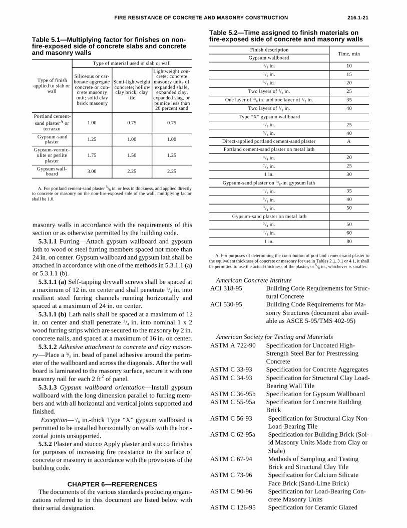
dst = column dimension, (see Fig. 3.3)dl = thickness of fire-exposed concrete layer (Section 2.2.5.2)
d = effective depth, distance from centroid of the tension reinforce-ment to extreme compressive fiber (Section 2.4.2)def = distance from the centroid of tension reinforcement to the
extreme concrete compressive fiber where the temperature does not exceed 1400 deg F (Section 2.4.2)
F = degrees Fahrenheitfc = measured compressive strength of concrete test cylinders at
ambient temperaturef'c = specified compressive strength of concrete
f'cθ = reduced compressive strength of concrete at elevated temperaturefps = stress in prestressing steel at nominal strength
fpsθ = reduced strength of prestressing steel at elevated temperaturefpu = specified tensile strength of prestressing tendonsfy = specified yield strength of non-prestressed reinforcing steel
fyθ = reduced strength of non-prestressed reinforcing steel at elevated temperature
H = specified height of masonry unitk = thermal conductivity at room temperatureL = specified length of masonry unit
l = span lengthM = moment due to full service load on the member
M+nθ = nominal positive moment flexural strength at section at ele-
vated temperatureM-
nθ = nominal negative moment flexural strength at section at ele-vated temperature
Mn = nominal flexural strength of memberMnθ = nominal flexural strength at section at elevated temperatureMx1 = maximum value of the redistributed positive moment at some
distance x1p = inner perimeter of concrete masonry protection
ps = heated perimeter of steel columnR = Fire resistance of assembly
R1, R2,...Rn = fire resistance of layer 1, 2,...n, respectivelys = spacing of ribs or undulationst = time in minutes
tmin = minimum thickness, in. (Section 2.2.4)ttot = total slab thickness (Section 2.2.5.2)TE = equivalent thickness of clay masonry unitTe = equivalent thickness of concrete masonry unit te = equivalent thickness of a ribbed or undulating concrete section
Tea = equivalent thickness of concrete masonry assemblyTef = equivalent thickness of finishestw = thickness of web, (see Fig. 3.3)u = average thickness of concrete between the center of main rein-
forcing steel and fire-exposed surfaceuef = an adjusted value of u to accommodate beam geometry
where fire exposure to concrete surfaces is from three sides (Chapter 2)
Vn = net volume of masonry unit
w = applied load (unfactored dead + live)x0 = distance from the inflection point after moment redistribution to the location of the first interior support (Chapter 2)
x1 = distance at which the maximum value of the redistributed posi-
tive moment occurs measured from: (a) the outer support for continuity over one support; and (b) either support where conti-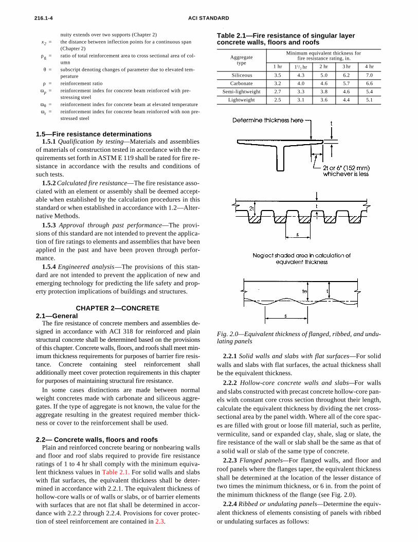
CHAPTER 2—CONCRETE
216.1-4 ACI STA
nuity extends over two supports (Chapter 2)
x2 = the distance between inflection points for a continuous span (Chapter 2)
ρg = ratio of total reinforcement area to cross sectional area of col-umn
θ = subscript denoting changes of parameter due to elevated tem-perature
ρ = reinforcement ratio
ωp = reinforcement index for concrete beam reinforced with pre-stressing steel
ωθ = reinforcement index for concrete beam at elevated temperature
ωr = reinforcement index for concrete beam reinforced with non pre-stressed steel
1.5—Fire resistance determinations1.5.1 Qualification by testing—Materials and assemblies
of materials of construction tested in accordance with the re-quirements set forth in ASTM E 119 shall be rated for fire re-sistance in accordance with the results and conditions ofsuch tests.
1.5.2 Calculated fire resistance—The fire resistance asso-ciated with an element or assembly shall be deemed accept-able when established by the calculation procedures in thisstandard or when established in accordance with 1.2—Alter-native Methods.
1.5.3 Approval through past performance—The provi-sions of this standard are not intended to prevent the applica-tion of fire ratings to elements and assemblies that have beenapplied in the past and have been proven through perfor-mance.
1.5.4 Engineered analysis—The provisions of this stan-dard are not intended to prevent the application of new andemerging technology for predicting the life safety and prop-erty protection implications of buildings and structures.
2.1—GeneralThe fire resistance of concrete members and assemblies de-
signed in accordance with ACI 318 for reinforced and plainstructural concrete shall be determined based on the provisionsof this chapter. Concrete walls, floors, and roofs shall meet min-imum thickness requirements for purposes of barrier fire resis-tance. Concrete containing steel reinforcement shalladditionally meet cover protection requirements in this chapterfor purposes of maintaining structural fire resistance.
In some cases distinctions are made between normalweight concretes made with carbonate and siliceous aggre-gates. If the type of aggregate is not known, the value for theaggregate resulting in the greatest required member thick-ness or cover to the reinforcement shall be used.
2.2— Concrete walls, floors and roofsPlain and reinforced concrete bearing or nonbearing walls
and floor and roof slabs required to provide fire resistanceratings of 1 to 4 hr shall comply with the minimum equiva-lent thickness values in Table 2.1. For solid walls and slabs
dance with 2.2.2 through 2.2.4. Provisions for cover protec-tion of steel reinforcement are contained in 2.3.
NDARD
l
Table 2.1—Fire resistance of singular layer concrete walls, floors and roofs
Aggregatetype
Minimum equivalent thickness for fire resistance rating, in.
1 hr 11/2 hr 2 hr 3 hr 4 hr
Siliceous 3.5 4.3 5.0 6.2 7.0
Carbonate 3.2 4.0 4.6 5.7 6.6
Semi-lightweight 2.7 3.3 3.8 4.6 5.4
Lightweight 2.5 3.1 3.6 4.4 5.1
with flat surfaces, the equivalent thickness shall be deter-mined in accordance with 2.2.1. The equivalent thickness of
2.2.1 Solid walls and slabs with flat surfaces—For solid
Fig. 2.0—Equivalent thickness of flanged, ribbed, and undu-lating panels
hollow-core walls or of walls or slabs, or of barrier elementswith surfaces that are not flat shall be determined in accor-
walls and slabs with flat surfaces, the actual thickness shallbe the equivalent thickness.
2.2.2 Hollow-core concrete walls and slabs—For wallsand slabs constructed with precast concrete hollow-core pan-els with constant core cross section throughout their length,calculate the equivalent thickness by dividing the net cross-sectional area by the panel width. Where all of the core spac-es are filled with grout or loose fill material, such as perlite,vermiculite, sand or expanded clay, shale, slag or slate, thefire resistance of the wall or slab shall be the same as that ofa solid wall or slab of the same type of concrete.
2.2.3 Flanged panels—For flanged walls, and floor androof panels where the flanges taper, the equivalent thicknessshall be determined at the location of the lesser distance oftwo times the minimum thickness, or 6 in. from the point ofthe minimum thickness of the flange (see Fig. 2.0).
2.2.4 Ribbed or undulating panels—Determine the equiv-
alent thickness of elements consisting of panels with ribbedor undulating surfaces as follows:
E
4) from Table 2.1 or Fig. 2.2 for concrete materials, from Ta-
tance in accordance with the graphical or numerical solu-
types of concrete, fire resistance shall be determined through
and roofs, the bottom surface shall be assumed to be exposedto fire.
2.2.5.2 Numerical solution—For floor and roof slabs andwalls made of one layer of normalweight concrete and onelayer of semi-lightweight or lightweight concrete, whereeach layer is 1 in. or greater in thickness, the combined fireresistance of the assembly shall be permitted to be deter-mined using the following expressions:
(a) When the fire-exposed layer is of normalweight concrete,
R = 0.057(2ttot2-dl ttot+6/ttot) (2-2)
(b) When the fire-exposed layer is of lightweight or semi-lightweight concrete,
R=0.063(ttot2+2dl ttot-dl
2+4/ttot) (2-3)
where
R = fire resistance, hrt = total thickness of slab, in.
FIRE RESISTANCE OF CONCRET
A. Where the center-to-center spacing of ribs or undula-tions is not less than four times the minimum thickness, theequivalent thickness is the minimum thickness of the panel.
B. Where the center-to-center spacing of ribs or undula-tions is equal to or less than two times the minimum thick-ness, calculate the equivalent thickness by dividing the netcross-sectional area by the panel width. The maximum thick-ness used to calculate the net cross-sectional area shall notexceed two times the minimum thickness.
C. Where the center-to-center spacing of ribs or undula-tions exceeds two times the minimum thickness but is lessthan four times the minimum thickness, calculate theequivalent thickness from the following equation:
Equivalent thickness = tmin+[(4tmin/s)-1](te-tmin) (2-1)
where:
s = spacing of ribs or undulations, in.tmin = minimum thickness, in.te = equivalent thickness, in., calculated in accordance
with Item B in 2.2.4
2.2.5 Multiple-layer walls, floors, and roofs—For walls,floors, and roofs consisting of two or more layers of differenttypes of concrete, masonry, or both, determine the fire resis-
insulated concrete floors and roofs shall be determined in ac-cordance with 2.2.6.
2.2.5.1 Graphical and analytical solutions—For solidwalls, floors, and roofs consisting of two layers of different
tot
2.2.5.3 Alternative numerical solution—For walls, floorsand roofs not meeting the criteria of 2.2.5.1, and consistingof two or more layers of different types of concrete, or of lay-
AND MASONRY CONSTRUCTION 216.1-5
dl = thickness of fire-exposed layer, in.
tions in 2.2.5.1, 2.2.5.2, or 2.2.5.3. The fire resistance of
the use of Fig. 2.1 or from Eq. (2-2) or (2-3). Perform sepa-rate fire resistance calculations assuming each side of the el-ement is the fire-exposed side. The fire resistance shall be thelower of the two resulting calculations unless otherwise per-mitted by the building code. Exception: In the cases of floors
ers of concrete, concrete masonry and/or clay masonry, de-termine the fire resistance from Eq. (2-4):
R = (R10.59+R2
0.59+...+Rn0.59+A1+A2+...+An)1.7 (2-4)
where
R = fire resistance of assembly, hrR1, R2 and Rn = fire resistance of individual layers, hr
A1, A2 and An = 0.30; the air factor for each continuous airspace having a distance of 1/2 in. to 31/2 in. between layers
Fig 2.1—Fire resistance of two-layer concrete walls, floors and roofs
Obtain values of Rn for individual layers for use in Eq. (2-
ble 3.1 for concrete masonry, and Table 4.1 for clay mason-ry. Interpolation between values in the tables shall bepermitted. Note: Eq. (2-4) does not consider which layer isbeing exposed to the fire.
2.2.5.4 Sandwich panels—Determine the fire resistance ofprecast concrete wall panels consisting of a layer of foamplastic sandwiched between two layers of concrete by usingEq. (2-4). For foam plastic with a thickness not less than 1
in., use Rn0.59 = 0.22 hr in Eq. (2-4). For foam plastic with atotal thickness less than 1 in., the fire resistance contribution
thickness of insulation by interpolation. Other approved joint
accordance with the provisions of Chapter 5.
2.3—Concrete cover protection of steel
on both sides with not less than 1 in. of concrete.
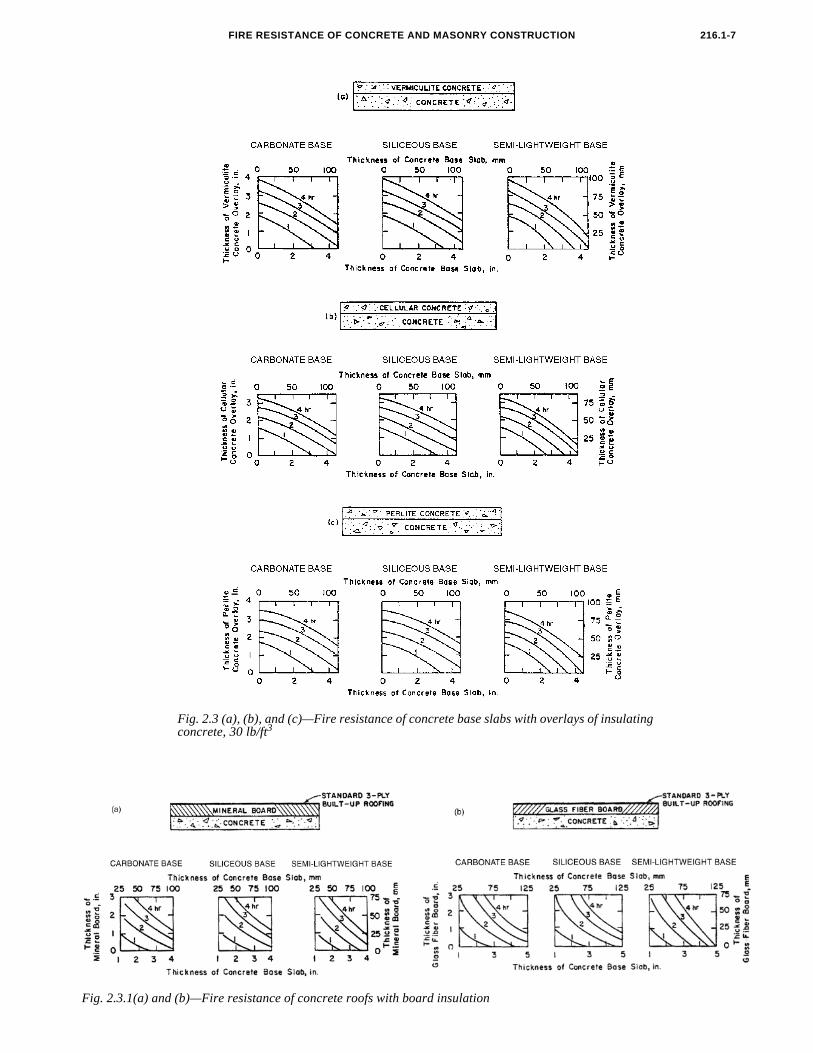
2.2.6 Insulated floors and roofs—Use Fig. 2.3 (a), (b) and
216.1-6 ACI ST
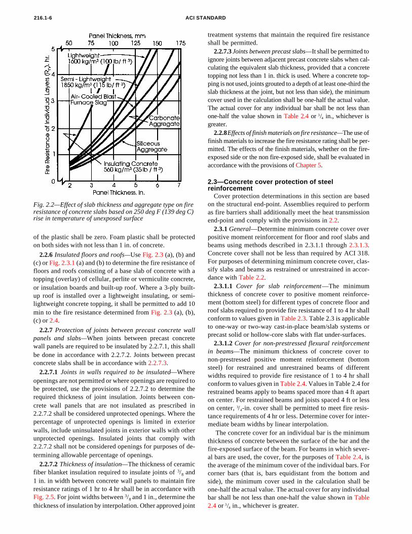
Fig. 2.2—Effect of slab thickness and aggregate type on fire
resistance of concrete slabs based on 250 deg F (139 deg C) rise in temperature of unexposed surfaceof the plastic shall be zero. Foam plastic shall be protected
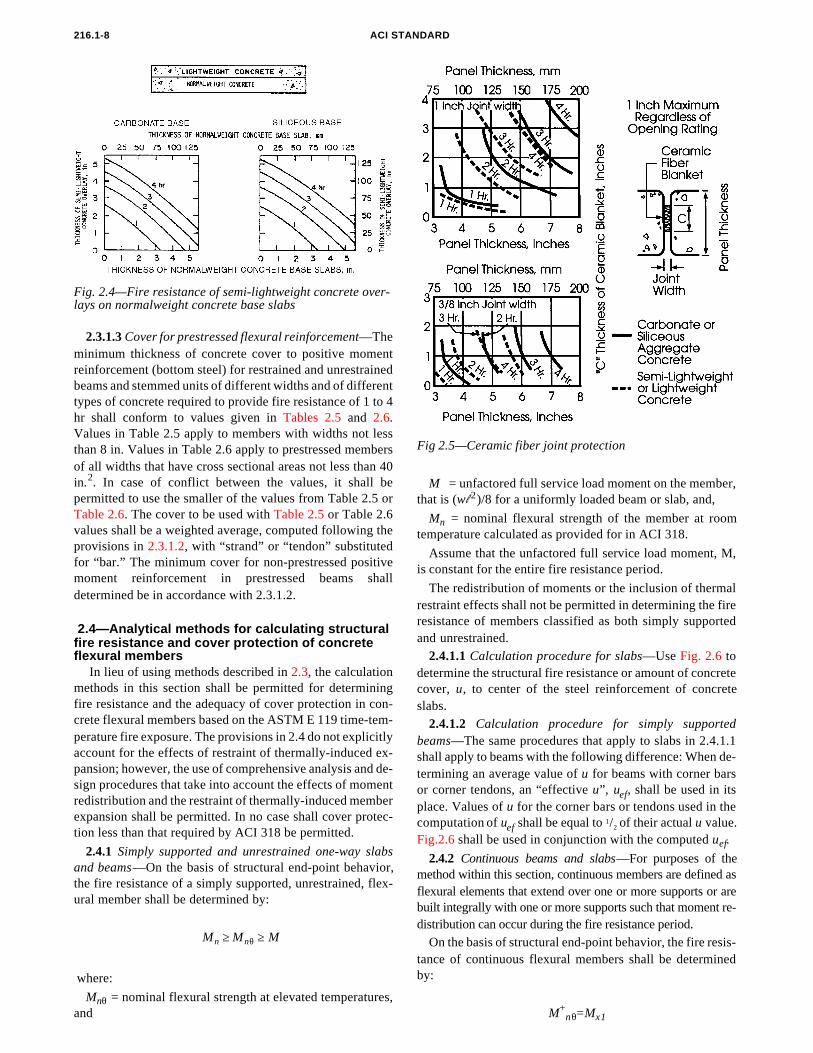
(c) or Fig. 2.3.1 (a) and (b) to determine the fire resistance offloors and roofs consisting of a base slab of concrete with atopping (overlay) of cellular, perlite or vermiculite concrete,or insulation boards and built-up roof. Where a 3-ply built-up roof is installed over a lightweight insulating, or semi-lightweight concrete topping, it shall be permitted to add 10min to the fire resistance determined from Fig. 2.3 (a), (b),(c) or 2.4.
2.2.7 Protection of joints between precast concrete wallpanels and slabs—When joints between precast concretewall panels are required to be insulated by 2.2.7.1, this shallbe done in accordance with 2.2.7.2. Joints between precast
shall be permitted.2.2.7.3 Joints between precast slabs—It shall be permitted to
ignore joints between adjacent precast concrete slabs when cal-culating the equivalent slab thickness, provided that a concretetopping not less than 1 in. thick is used. Where a concrete top-ping is not used, joints grouted to a depth of at least one-third theslab thickness at the joint, but not less than side), the minimumcover used in the calculation shall be one-half the actual value.The actual cover for any individual bar shall be not less than
concrete slabs shall be in accordance with 2.2.7.3.2.2.7.1 Joints in walls required to be insulated—Where
openings are not permitted or where openings are required tobe protected, use the provisions of 2.2.7.2 to determine therequired thickness of joint insulation. Joints between con-crete wall panels that are not insulated as prescribed in2.2.7.2 shall be considered unprotected openings. Where thepercentage of unprotected openings is limited in exteriorwalls, include uninsulated joints in exterior walls with otherunprotected openings. Insulated joints that comply with2.2.7.2 shall not be considered openings for purposes of de-termining allowable percentage of openings.
2.2.7.2 Thickness of insulation—The thickness of ceramicfiber blanket insulation required to insulate joints of 3/8 and1 in. in width between concrete wall panels to maintain fireresistance ratings of 1 hr to 4 hr shall be in accordance with
Fig. 2.5. For joint widths between 3/8 and 1 in., determine theANDARD
treatment systems that maintain the required fire resistance
one-half the value shown in Table 2.4 or 3/4 in., whichever isgreater.
2.2.8 Effects of finish materials on fire resistance—The use offinish materials to increase the fire resistance rating shall be per-mitted. The effects of the finish materials, whether on the fire-exposed side or the non fire-exposed side, shall be evaluated in
reinforcementCover protection determinations in this section are based
on the structural end-point. Assemblies required to performas fire barriers shall additionally meet the heat transmissionend-point and comply with the provisions in 2.2.
2.3.1 General—Determine minimum concrete cover overpositive moment reinforcement for floor and roof slabs and
dance with Table 2.2.2.3.1.1 Cover for slab reinforcement—The minimum
thickness of concrete cover to positive moment reinforce-ment (bottom steel) for different types of concrete floor androof slabs required to provide fire resistance of 1 to 4 hr shall
conform to values given in Table 2.3. Table 2.3 is applicableto one-way or two-way cast-in-place beam/slab systems orprecast solid or hollow-core slabs with flat under-surfaces.2.3.1.2 Cover for non-prestressed flexural reinforcementin beams—The minimum thickness of concrete cover tonon-prestressed positive moment reinforcement (bottomsteel) for restrained and unrestrained beams of differentwidths required to provide fire resistance of 1 to 4 hr shallconform to values given in Table 2.4. Values in Table 2.4 forrestrained beams apply to beams spaced more than 4 ft aparton center. For restrained beams and joists spaced 4 ft or lesson center, 3/4-in. cover shall be permitted to meet fire resis-tance requirements of 4 hr or less. Determine cover for inter-mediate beam widths by linear interpolation.
The concrete cover for an individual bar is the minimumthickness of concrete between the surface of the bar and thefire-exposed surface of the beam. For beams in which sever-al bars are used, the cover, for the purposes of Table 2.4, isthe average of the minimum cover of the individual bars. Forcorner bars (that is, bars equidistant from the bottom andside), the minimum cover used in the calculation shall beone-half the actual value. The actual cover for any individualbar shall be not less than one-half the value shown in Table
beams using methods described in 2.3.1.1 through 2.3.1.3.Concrete cover shall not be less than required by ACI 318.For purposes of determining minimum concrete cover, clas-sify slabs and beams as restrained or unrestrained in accor-
2.4 or 3/4 in., whichever is greater.
216.1-7FIRE RESISTANCE OF CONCRETE AND MASONRY CONSTRUCTION
Fig. 2.3 (a), (b), and (c)—Fire resistance of concrete base slabs with overlays of insulating concrete, 30 lb/ft3
Fig. 2.3.1(a) and (b)—Fire resistance of concrete roofs with board insulation
ACI STANDARD216.1-8
where:
Mnθ = nominal flexural strength at elevated temperatures,and
determine the structural fire resistance or amount of concrete
2.4.2 Continuous beams and slabs—For purposes of themethod within this section, continuous members are defined asflexural elements that extend over one or more supports or arebuilt integrally with one or more supports such that moment re-distribution can occur during the fire resistance period.
On the basis of structural end-point behavior, the fire resis-tance of continuous flexural members shall be determinedby:
2.3.1.3 Cover for prestressed flexural reinforcement—Theminimum thickness of concrete cover to positive momentreinforcement (bottom steel) for restrained and unrestrainedbeams and stemmed units of different widths and of differenttypes of concrete required to provide fire resistance of 1 to 4hr shall conform to values given in Tables 2.5 and 2.6.
Fig. 2.4—Fire resistance of semi-lightweight concrete over-lays on normalweight concrete base slabs
Values in Table 2.5 apply to members with widths not lessthan 8 in. Values in Table 2.6 apply to prestressed membersof all widths that have cross sectional areas not less than 40in.2. In case of conflict between the values, it shall bepermitted to use the smaller of the values from Table 2.5 orTable 2.6. The cover to be used with Table 2.5 or Table 2.6values shall be a weighted average, computed following theprovisions in 2.3.1.2, with “strand” or “tendon” substitutedfor “bar.” The minimum cover for non-prestressed positivemoment reinforcement in prestressed beams shalldetermined be in accordance with 2.3.1.2.
2.4—Analytical methods for calculating structural fire resistance and cover protection of concrete flexural members
In lieu of using methods described in 2.3, the calculationmethods in this section shall be permitted for determiningfire resistance and the adequacy of cover protection in con-crete flexural members based on the ASTM E 119 time-tem-perature fire exposure. The provisions in 2.4 do not explicitlyaccount for the effects of restraint of thermally-induced ex-pansion; however, the use of comprehensive analysis and de-sign procedures that take into account the effects of momentredistribution and the restraint of thermally-induced memberexpansion shall be permitted. In no case shall cover protec-tion less than that required by ACI 318 be permitted.
2.4.1 Simply supported and unrestrained one-way slabsand beams—On the basis of structural end-point behavior,the fire resistance of a simply supported, unrestrained, flex-ural member shall be determined by:
Mn Mnθ M≥ ≥
M = unfactored full service load moment on the member,that is (wl 2)/8 for a uniformly loaded beam or slab, and,
Mn = nominal flexural strength of the member at roomtemperature calculated as provided for in ACI 318.
Assume that the unfactored full service load moment, M,is constant for the entire fire resistance period.
The redistribution of moments or the inclusion of thermalrestraint effects shall not be permitted in determining the fireresistance of members classified as both simply supportedand unrestrained.
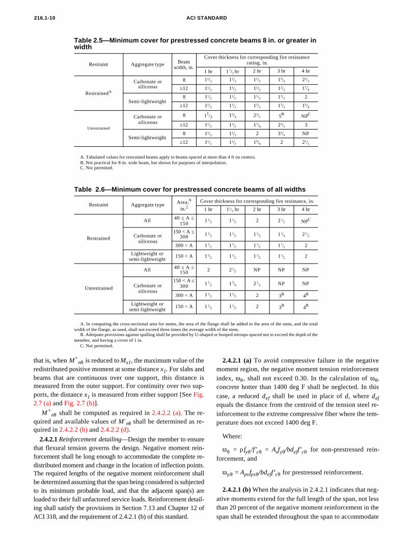
2.4.1.1 Calculation procedure for slabs—Use Fig. 2.6 to
Fig 2.5—Ceramic fiber joint protection
cover, u, to center of the steel reinforcement of concreteslabs.
2.4.1.2 Calculation procedure for simply supportedbeams—The same procedures that apply to slabs in 2.4.1.1shall apply to beams with the following difference: When de-termining an average value of u for beams with corner barsor corner tendons, an “effective u”, uef, shall be used in itsplace. Values of u for the corner bars or tendons used in thecomputation of uef shall be equal to 1/2 of their actual u value.Fig.2.6 shall be used in conjunction with the computed uef.
M+nθ=Mx1
216.1-9FIRE RESISTANCE OF CONCRETE AND MASONRY CONSTRUCTION
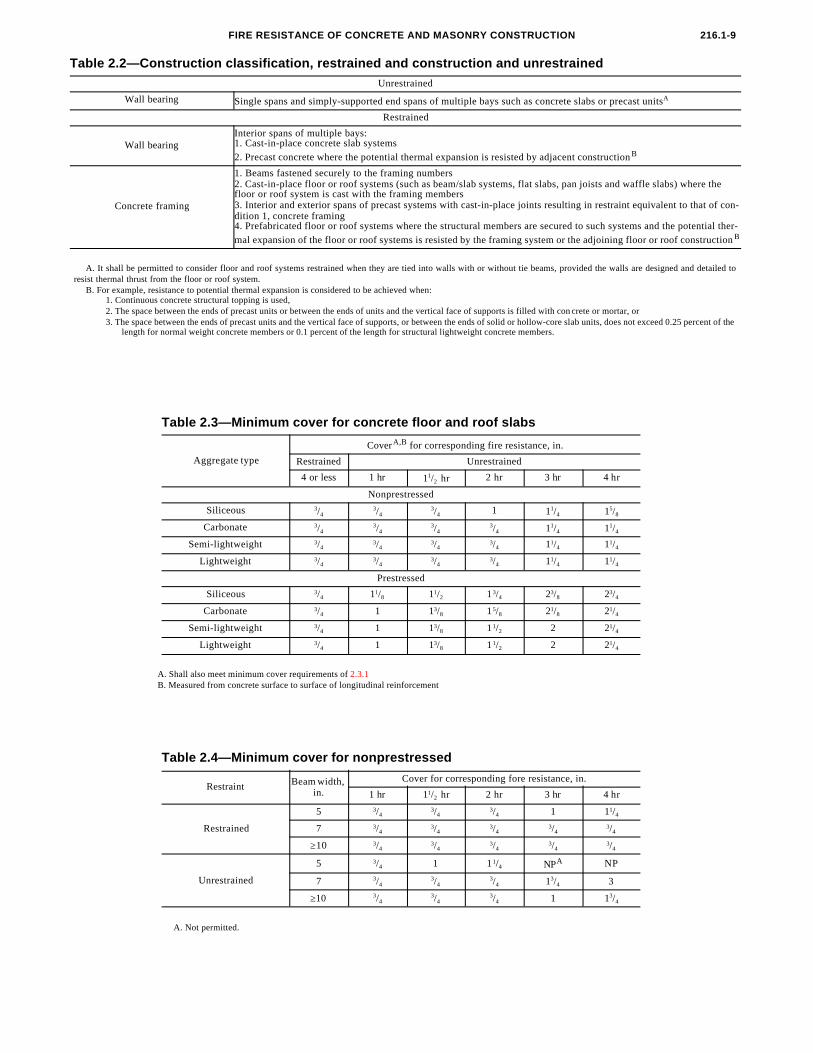
A. Not permitted.
Table 2.4—Minimum cover for nonprestressed
Restraint Beam width, in.
Cover for corresponding fore resistance, in.
1 hr 11/2 hr 2 hr 3 hr 4 hr
Restrained
5 3/43/4
3/4 1 11/4
7 3/43/4
3/43/4
3/4
≥10 3/43/4
3/43/4
3/4
Unrestrained
5 3/4 1 1 1/4 NPA NP
7 3/43/4
3/4 13/4 3
≥10 3/43/4
3/4 1 13/4
A. Shall also meet minimum cover requirements of 2.3.1B. Measured from concrete surface to surface of longitudinal reinforcement
Table 2.3—Minimum cover for concrete floor and roof slabs
Aggregate type
CoverA,B for corresponding fire resistance, in.
Restrained Unrestrained
4 or less 1 hr 11/2 hr 2 hr 3 hr 4 hr
Nonprestressed
Siliceous 3/43/4
3/4 1 11/4 15/8
Carbonate 3/43/4
3/43/4 11/4 11/4
Semi-lightweight 3/43/4
3/43/4 11/4 11/4
Lightweight 3/43/4
3/43/4 11/4 11/4
Prestressed
Siliceous 3/4 11/8 11/2 13/4 23/8 23/4
Carbonate 3/4 1 13/8 15/8 21/8 21/4
Semi-lightweight 3/4 1 13/8 11/2 2 21/4
Lightweight 3/4 1 13/8 11/2 2 21/4
A. It shall be permitted to consider floor and roof systems restrained when they are tied into walls with or without tie beams, provided the walls are designed and detailed toresist thermal thrust from the floor or roof system.
B. For example, resistance to potential thermal expansion is considered to be achieved when:1. Continuous concrete structural topping is used,2. The space between the ends of precast units or between the ends of units and the vertical face of supports is filled with con crete or mortar, or3. The space between the ends of precast units and the vertical face of supports, or between the ends of solid or hollow-core slab units, does not exceed 0.25 percent of the
length for normal weight concrete members or 0.1 percent of the length for structural lightweight concrete members.
Table 2.2—Construction classification, restrained and construction and unrestrainedUnrestrained
Wall bearing Single spans and simply-supported end spans of multiple bays such as concrete slabs or precast unitsA
Restrained
Wall bearingInterior spans of multiple bays:1. Cast-in-place concrete slab systems
2. Precast concrete where the potential thermal expansion is resisted by adjacent construction B
Concrete framing
1. Beams fastened securely to the framing numbers2. Cast-in-place floor or roof systems (such as beam/slab systems, flat slabs, pan joists and waffle slabs) where the floor or roof system is cast with the framing members3. Interior and exterior spans of precast systems with cast-in-place joints resulting in restraint equivalent to that of con-dition 1, concrete framing4. Prefabricated floor or roof systems where the structural members are secured to such systems and the potential ther-
mal expansion of the floor or roof systems is resisted by the framing system or the adjoining floor or roof construction B
216.1-10 ACI STANDARD
A. Tabulated values for restrained beams apply to beams spaced at more than 4 ft on centers.B. Not practical for 8-in. wide beam, but shown for purposes of interpolation.C. Not permitted.
Table 2.5—Minimum cover for prestressed concrete beams 8 in. or greater in width
Restraint Aggregate type Beam width, in.
Cover thickness for corresponding fire resistancerating, in.
1 hr 11/2 hr 2 hr 3 hr 4 hr
RestrainedA
Carbonate orsiliceous
8 11/2 11/2 11/2 13/4 21/2
≥12 11/2 11/2 11/2 11/2 17/8
Semi-lightweight8 11/2 11/2 11/2 11/2 2
≥12 11/2 11/2 11/2 11/2 15/8
Unrestrained
Carbonate orsiliceous
8 11/2 13/4 21/2 5B NPC
≥12 11/2 11/2 17/8 21/2 3
Semi-lightweight8 11/2 11/2 2 31/4 NP
≥12 11/2 11/2 15/8 2 21/2
A. In computing the cross-sectional area for stems, the area of the flange shall be added to the area of the stem, and the totalwidth of the flange, as used, shall not exceed three times the average width of the stem.
B. Adequate provisions against spalling shall be provided by U-shaped or hooped stirrups spaced not to exceed the depth of themember, and having a cover of 1 in.
C. Not permitted.
Table 2.6—Minimum cover for prestressed concrete beams of all widths
Restraint Aggregate type Area,A in.2
Cover thickness for corresponding fire resistance, in.
1 hr 11/2 hr 2 hr 3 hr 4 hr
Restrained
All 40 ≤ Α ≤ 150 11/2 11/2 2 2 1/2 NPC
Carbonate orsiliceous
150 < Α ≤ 300 11/2 11/2 11/2 13/4 21/2
300 < A 11/2 11/2 11/2 11/2 2
Lightweight orsemi-lightweight
150 < A 11/2 11/2 11/2 11/2 2
Unrestrained
All 40 ≤ Α ≤ 150 2 2 1/2 NP NP NP
Carbonate orsiliceous
150 < A ≤ 300 11/2 13/4 21/2 NP NP
300 < A 11/2 11/2 2 3B 4B
Lightweight orsemi-lightweight
150 < A 11/2 11/2 2 3B 4B
+
that is, when M nθ is reduced to Mx1, the maximum value of theredistributed positive moment at some distance x1. For slabs andbeams that are continuous over one support, this distance ismeasured from the outer support. For continuity over two sup-ports, the distance x1 is measured from either support [See Fig.2.7 (a) and Fig. 2.7 (b)].M+nθ shall be computed as required in 2.4.2.2 (a). The re-
quired and available values of M-nθ shall be determined as re-
quired in 2.4.2.2 (b) and 2.4.2.2 (d).
2.4.2.1 Reinforcement detailing—Design the member to ensure
that flexural tension governs the design. Negative moment rein-forcement shall be long enough to accommodate the complete re- distributed moment and change in the location of inflection points.The required lengths of the negative moment reinforcement shallbe determined assuming that the span being considered is subjectedto its minimum probable load, and that the adjacent span(s) areloaded to their full unfactored service loads. Reinforcement detail-ing shall satisfy the provisions in Section 7.13 and Chapter 12 of ACI 318, and the requirement of 2.4.2.1 (b) of this standard.2.4.2.1 (a) To avoid compressive failure in the negativemoment region, the negative moment tension reinforcementindex, ωθ, shall not exceed 0.30. In the calculation of ωθ,concrete hotter than 1400 deg F shall be neglected. In thiscase, a reduced def shall be used in place of d, where def
equals the distance from the centroid of the tension steel re-
inforcement to the extreme compressive fiber where the tem-perature does not exceed 1400 deg F.Where:
ωθ = ρfyθ/f’cθ = Asfyθ/bdeff’cθ for non-prestressed rein-forcement, and
ωρθ = Apsfpsθ/bdeff’cθ for prestressed reinforcement.
2.4.2.1 (b) When the analysis in 2.4.2.1 indicates that neg-ative moments extend for the full length of the span, not lessthan 20 percent of the negative moment reinforcement in the
span shall be extended throughout the span to accommodate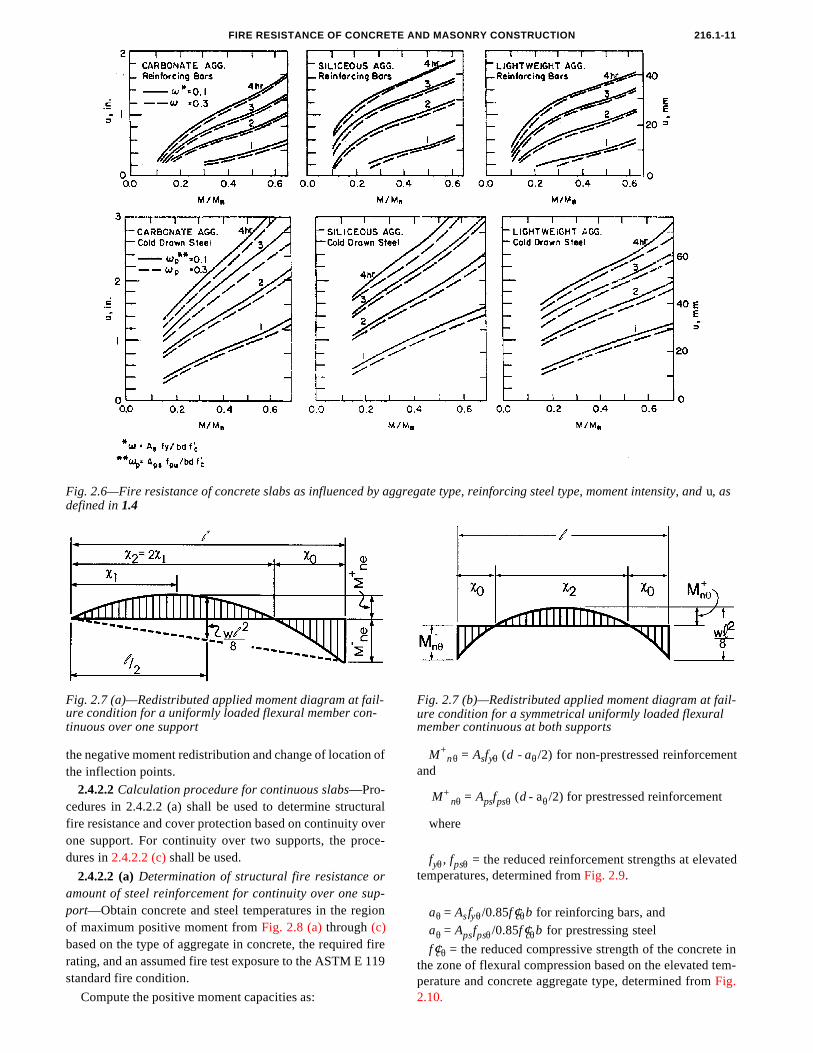
FIRE RESISTANCE OF CONCRETE AND MASONRY CONSTRUCTION 216.1-11
gre
Fig. 2.6—Fire resistance of concrete slabs as influenced by agdefined in 1.4Fig. 2.7 (a)—Redistributed applied moment diagram at fail-ure condition for a uniformly loaded flexural member con-tinuous over one support
Compute the positive moment capacities as:
gate type, reinforcing steel type, moment intensity, and u, as
Fig. 2.7 (b)—Redistributed applied moment diagram at fail-ure condition for a symmetrical uniformly loaded flexural
nθ s yθ θand
M+nθ = Apsfpsθ (d - aθ/2) for prestressed reinforcement
where
one support. For continuity over two supports, the proce-dures in 2.4.2.2 (c) shall be used.2.4.2.2 (a) Determination of structural fire resistance oramount of steel reinforcement for continuity over one sup-port—Obtain concrete and steel temperatures in the regionof maximum positive moment from Fig. 2.8 (a) through (c)based on the type of aggregate in concrete, the required firerating, and an assumed fire test exposure to the ASTM E 119standard fire condition.
the negative moment redistribution and change of location ofthe inflection points.
2.4.2.2 Calculation procedure for continuous slabs—Pro-cedures in 2.4.2.2 (a) shall be used to determine structuralfire resistance and cover protection based on continuity over
M+ = A f (d - a /2) for non-prestressed reinforcement
member continuous at both supports
fyθ, fpsθ = the reduced reinforcement strengths at elevatedtemperatures, determined from Fig. 2.9.
aθ = Asfyθ/0.85f ′cθb for reinforcing bars, andaθ = Apsfpsθ/0.85f ′cθb for prestressing steel
f ′cθ = the reduced compressive strength of the concrete inthe zone of flexural compression based on the elevated tem-perature and concrete aggregate type, determined from Fig.
2.10.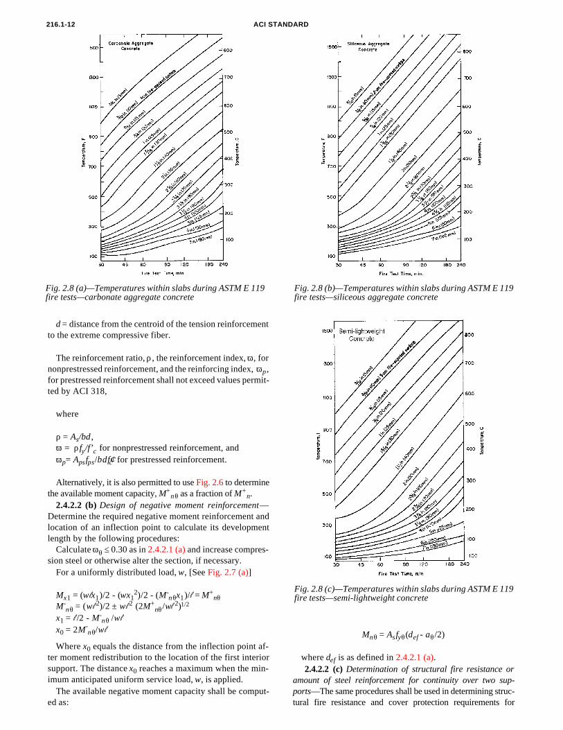
216.1-12 ACI STANDARD
Fig. 2.8 (a)—Temperatures within slabs during ASTM E 119 fire tests—carbonate aggregate concrete
Fig. 2.8 (b)—Temperatures within slabs during ASTM E 119 fire tests—siliceous aggregate concrete
The available negative moment capacity shall be comput-ed as:
Fig. 2.8 (c)—Temperatures within slabs during ASTM E 119
nθ nθx1 = l /2 - M-
nθ /wl
x0 = 2M-nθ/wl
Where x0 equals the distance from the inflection point af-ter moment redistribution to the location of the first interiorsupport. The distance x0 reaches a maximum when the min-imum anticipated uniform service load, w, is applied.
d = distance from the centroid of the tension reinforcementto the extreme compressive fiber.
The reinforcement ratio, ρ, the reinforcement index, ω, for
nonprestressed reinforcement, and the reinforcing index, ωp ,for prestressed reinforcement shall not exceed values permit-ted by ACI 318,where
ρ = As/bd , ω = ρfy/f’c for nonprestressed reinforcement, andωp= Apsfps/bdf′c for prestressed reinforcement.
Alternatively, it is also permitted to use Fig. 2.6 to determinethe available moment capacity, M+
nθ as a fraction of M+n.
2.4.2.2 (b) Design of negative moment reinforcement—Determine the required negative moment reinforcement andlocation of an inflection point to calculate its developmentlength by the following procedures:
Calculate ωθ ≤ 0.30 as in 2.4.2.1 (a) and increase compres-sion steel or otherwise alter the section, if necessary.
For a uniformly distributed load, w, [See Fig. 2.7 (a)]
Mx1 = (wlx1)/2 - (wx12)/2 - (M-
nθx1)/l = M+nθ
M- = (wl 2)/2 ± wl 2 (2M+ /wl 2)1/2
fire tests—semi-lightweight concreteMnθ = Asfyθ(def - aθ/2)
where def is as defined in 2.4.2.1 (a). 2.4.2.2 (c) Determination of structural fire resistance or
amount of steel reinforcement for continuity over two sup-
ports—The same procedures shall be used in determining struc-tural fire resistance and cover protection requirements for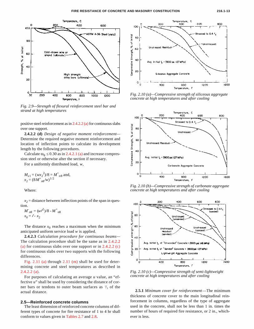
216.1-13FIRE RESISTANCE OF CONCRETE AND MASONRY CONSTRUCTION
Fig. 2.9—Strength of flexural reinforcement steel bar and
Where:
x2 = distance between inflection points of the span in ques-tion.
M-nθ = (wl 2)/8 - M+
nθx0 = l - x2
The distance x0 reaches a maximum when the minimumanticipated uniform service load w is applied.
2.4.2.3 Calculation procedure for continuous beams—The calculation procedure shall be the same as in 2.4.2.2(a) for continuous slabs over one support or in 2.4.2.2 (c)for continuous slabs over two supports with the followingdifferences.
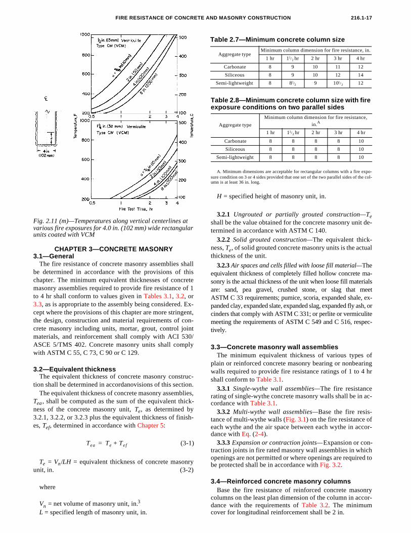
Fig. 2.11 (a) through 2.11 (m) shall be used for deter-mining concrete and steel temperatures as described in2.4.2.2 (a).
For purposes of calculating an average u value, an “ef-fective u” shall be used by considering the distance of cor-ner bars or tendons to outer beam surfaces as 1/2 of theactual distance.
sion steel or otherwise alter the section if necessary.For a uniformly distributed load, w,
Mx1 = (wx22)/8 = M+
nθ and,x2 = (8M+
nθ/w)1/2
ferent types of concrete for fire resistance of 1 to 4 hr shallconform to values given in Tables 2.7 and 2.8.
Fig. 2.10 (a)—Compressive strength of siliceous aggregate concrete at high temperatures and after cooling
Fig. 2.10 (b)—Compressive strength of carbonate aggregate concrete at high temperatures and after cooling
strand at high temperatures
positive steel reinforcement as in 2.4.2.2 (a) for continuous slabsover one support.
2.4.2.2 (d) Design of negative moment reinforcement—Determine the required negative moment reinforcement andlocation of inflection points to calculate its developmentlength by the following procedures.
Calculate ωθ ≤ 0.30 as in 2.4.2.1 (a) and increase compres-
2.5—Reinforced concrete columnsThe least dimension of reinforced concrete columns of dif-
Fig. 2.10 (c)—Compressive strength of semi-lightweight concrete at high temperatures and after cooling
2.5.1 Minimum cover for reinforcement—The minimumthickness of concrete cover to the main longitudinal rein-forcement in columns, regardless of the type of aggregateused in the concrete, shall not be less than 1 in. times the
number of hours of required fire resistance, or 2 in., which-ever is less.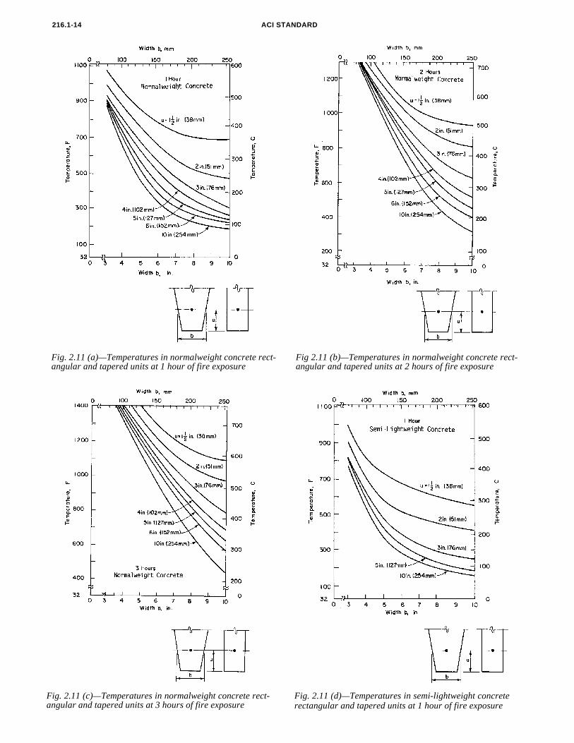
ACI STANDARD216.1-14
Fig. 2.11 (a)—Temperatures in normalweight concrete rect-angular and tapered units at 1 hour of fire exposure
Fig 2.11 (b)—Temperatures in normalweight concrete rect-angular and tapered units at 2 hours of fire exposure
Fig. 2.11 (c)—Temperatures in normalweight concrete rect-angular and tapered units at 3 hours of fire exposure
Fig. 2.11 (d)—Temperatures in semi-lightweight concrete rectangular and tapered units at 1 hour of fire exposure
216.1-15FIRE RESISTANCE OF CONCRETE AND MASONRY CONSTRUCTION
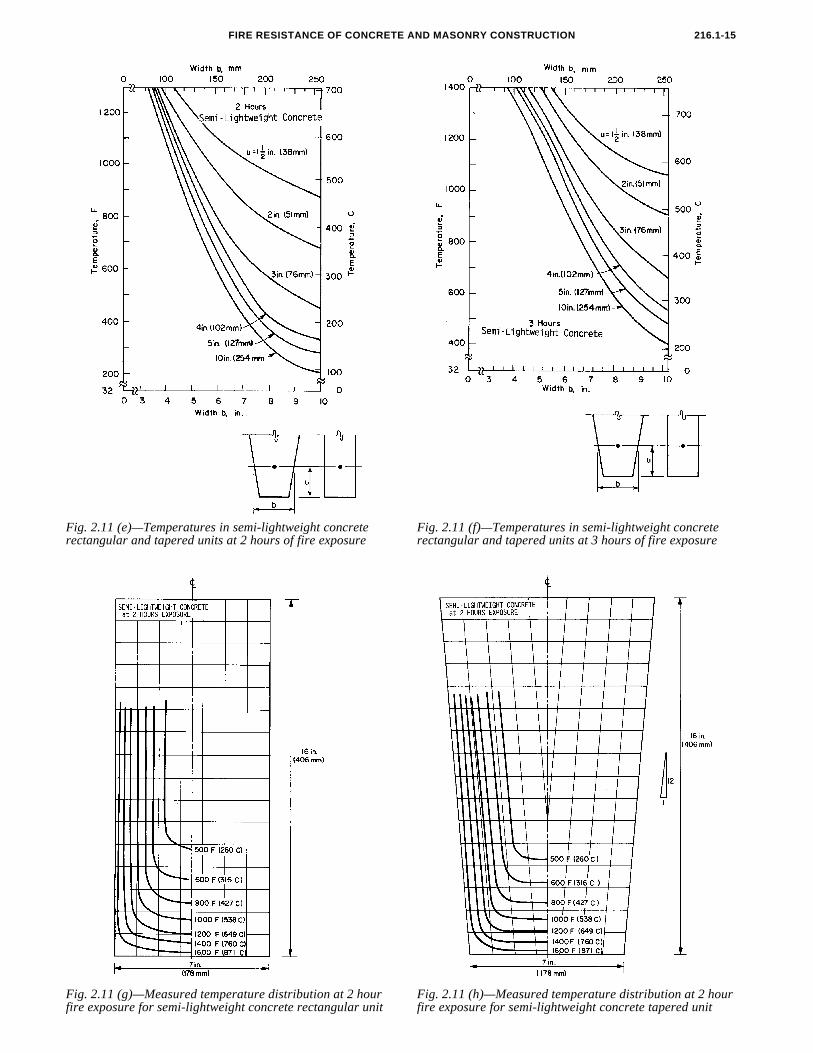
Fig. 2.11 (e)—Temperatures in semi-lightweight concrete rectangular and tapered units at 2 hours of fire exposure
Fig. 2.11 (f)—Temperatures in semi-lightweight concrete rectangular and tapered units at 3 hours of fire exposure
Fig. 2.11 (g)—Measured temperature distribution at 2 hour Fig. 2.11 (h)—Measured temperature distribution at 2 hour
fire exposure for semi-lightweight concrete rectangular unit fire exposure for semi-lightweight concrete tapered unit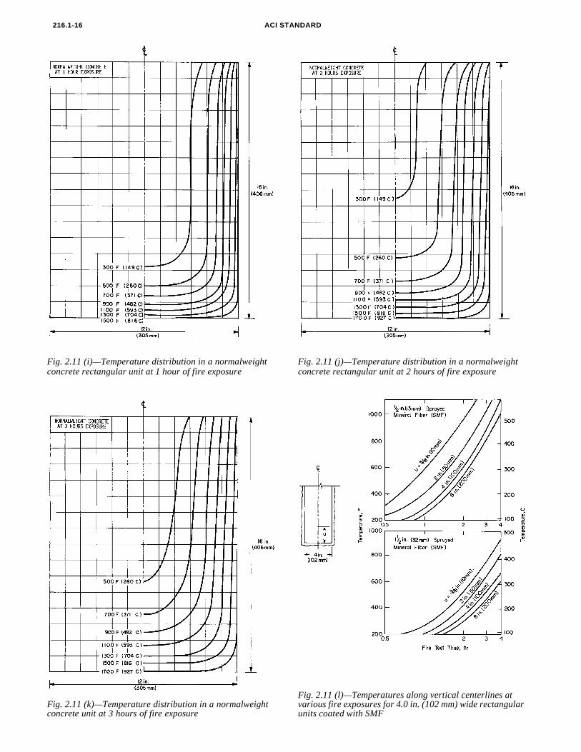
ACI STANDARD216.1-16
Fig. 2.11 (i)—Temperature distribution in a normalweight concrete rectangular unit at 1 hour of fire exposure
Fig. 2.11 (j)—Temperature distribution in a normalweight concrete rectangular unit at 2 hours of fire exposure
Fig. 2.11 (k)—Temperature distribution in a normalweight Fig. 2.11 (l)—Temperatures along vertical centerlines at various fire exposures for 4.0 in. (102 mm) wide rectangular
concrete unit at 3 hours of fire exposure units coated with SMF
FIRE RESISTANCE OF CONCRETE AND MASONRY CONSTRUCTION 216.1-17
meeting the requirements of ASTM C 549 and C 516, respec-
with ASTM C 55, C 73, C 90 or C 129.
Fig. 2.11 (m)—Temperatures along vertical centerlines at various fire exposures for 4.0 in. (102 mm) wide rectangular units coated with VCM
CHAPTER 3—CONCRETE MASONRY
3.1—GeneralThe fire resistance of concrete masonry assemblies shallbe determined in accordance with the provisions of thischapter. The minimum equivalent thicknesses of concretemasonry assemblies required to provide fire resistance of 1
Vn = net volume of masonry unit, in.L = specified length of masonry unit, in.
A. Minimum dimensions are acceptable for rectangular columns with a fire expo-
Table 2.8—Minimum concrete column size with fire exposure conditions on two parallel sides
Aggregate type
Minimum column dimension for fire resistance,
in.A
1 hr 11/2 hr 2 hr 3 hr 4 hr
Carbonate 8 8 8 8 10
Siliceous 8 8 8 8 10
Semi-lightweight 8 8 8 8 10
Table 2.7—Minimum concrete column size
Aggregate typeMinimum column dimension for fire resistance, in.
1 hr 11/2 hr 2 hr 3 hr 4 hr
Carbonate 8 9 10 11 12
Siliceous 8 9 10 12 14
Semi-lightweight 8 81/2 9 101/2 12
to 4 hr shall conform to values given in Tables 3.1, 3.2, or3.3, as is appropriate to the assembly being considered. Ex-cept where the provisions of this chapter are more stringent,the design, construction and material requirements of con-crete masonry including units, mortar, grout, control jointmaterials, and reinforcement shall comply with ACI 530/ASCE 5/TMS 402. Concrete masonry units shall comply
3.2—Equivalent thicknessThe equivalent thickness of concrete masonry construc-
tion shall be determined in accordanovisions of this section.The equivalent thickness of concrete masonry assemblies,
Tea , shall be computed as the sum of the equivalent thick-ness of the concrete masonry unit, Te, as determined by
3.2.1, 3.2.2, or 3.2.3 plus the equivalent thickness of finish-es, Tef, determined in accordance with Chapter 5:(3-1)
Te = Vn/LH = equivalent thickness of concrete masonryunit, in. (3-2)
where
3
Tea Te Tef+=
H = specified height of masonry unit, in.
sure condition on 3 or 4 sides provided that one set of the two parallel sides of the col-umn is at least 36 in. long.
tively.
3.3—Concrete masonry wall assembliesThe minimum equivalent thickness of various types of
plain or reinforced concrete masonry bearing or nonbearingwalls required to provide fire resistance ratings of 1 to 4 hrshall conform to Table 3.1.
3.3.1 Single-wythe wall assemblies—The fire resistancerating of single-wythe concrete masonry walls shall be in ac-cordance with Table 3.1.
3.3.2 Multi-wythe wall assemblies—Base the fire resis-tance of multi-wythe walls (Fig. 3.1) on the fire resistance ofeach wythe and the air space between each wythe in accor-dance with Eq. (2-4).
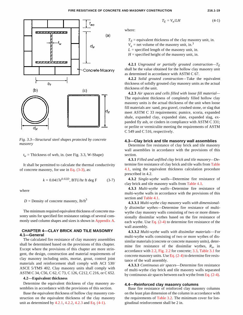
3.3.3 Expansion or contraction joints—Expansion or con-
3.2.1 Ungrouted or partially grouted construction—Teshall be the value obtained for the concrete masonry unit de-termined in accordance with ASTM C 140.
3.2.2 Solid grouted construction—The equivalent thick-ness, Te, of solid grouted concrete masonry units is the actualthickness of the unit.
3.2.3 Air spaces and cells filled with loose fill material—Theequivalent thickness of completely filled hollow concrete ma-sonry is the actual thickness of the unit when loose fill materialsare: sand, pea gravel, crushed stone, or slag that meetASTM C 33 requirements; pumice, scoria, expanded shale, ex-panded clay, expanded slate, expanded slag, expanded fly ash, orcinders that comply with ASTM C 331; or perlite or vermiculite
traction joints in fire rated masonry wall assemblies in whichopenings are not permitted or where openings are required tobe protected shall be in accordance with Fig. 3.2.
3.4—Reinforced concrete masonry columnsBase the fire resistance of reinforced concrete masonry
columns on the least plan dimension of the column in accor-
dance with the requirements of Table 3.2. The minimumcover for longitudinal reinforcement shall be 2 in.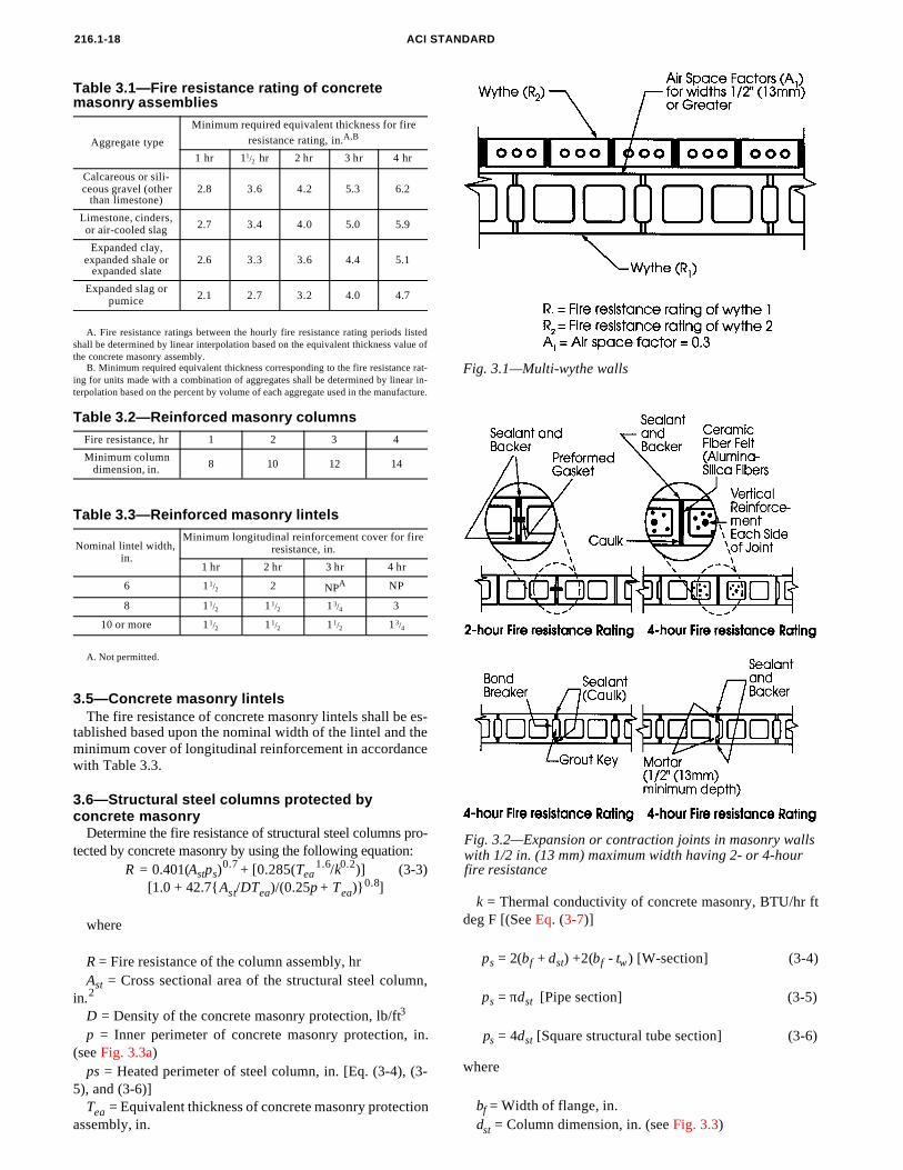
A
st ea ea
Tea = Equivalent thickness of concrete masonry protectionassembly, in.
A. Not permitted.
F
216.1-18 ACI ST
A. Fire resistance ratings between the hourly fire resistance rating periods listedshall be determined by linear interpolation based on the equivalent thickness value ofthe concrete masonry assembly.
Table 3.1—Fire resistance rating of concrete masonry assemblies
Aggregate type
Minimum required equivalent thickness for fire
resistance rating, in.A,B
1 hr 11/2 hr 2 hr 3 hr 4 hr
Calcareous or sili-ceous gravel (other
than limestone)2.8 3.6 4.2 5.3 6.2
Limestone, cinders, or air-cooled slag 2.7 3.4 4.0 5.0 5.9
Expanded clay, expanded shale or
expanded slate2.6 3.3 3.6 4.4 5.1
Expanded slag or pumice 2.1 2.7 3.2 4.0 4.7
B. Minimum required equivalent thickness corresponding to the fire resistance rat-ing for units made with a combination of aggregates shall be determined by linear in-terpolation based on the percent by volume of each aggregate used in the manufacture.
Table 3.2—Reinforced masonry columnsFire resistance, hr 1 2 3 4
Minimum column dimension, in. 8 10 12 14
Table 3.3—Reinforced masonry lintels
Nominal lintel width, in.
Minimum longitudinal reinforcement cover for fire resistance, in.
1 hr 2 hr 3 hr 4 hr
6 1 1/2 2 NPA NP
8 1 1/2 11/2 13/4 3
10 or more 11/2 11/2 11/2 13/4
3.5—Concrete masonry lintelsThe fire resistance of concrete masonry lintels shall be es-
tablished based upon the nominal width of the lintel and theminimum cover of longitudinal reinforcement in accordancewith Table 3.3.
NDARD
3.6—Structural steel columns protected by concrete masonry
Determine the fire resistance of structural steel columns pro-tected by concrete masonry by using the following equation:
R = 0.401(Astps)0.7 + [0.285(Tea
1.6/k0.2)] (3-3) [1.0 + 42.7{A /DT )/(0.25p + T )}0.8]
ig. 3.1—Multi-wythe walls
where
R = Fire resistance of the column assembly, hrAst = Cross sectional area of the structural steel column,
in.2
D = Density of the concrete masonry protection, lb/ft3
p = Inner perimeter of concrete masonry protection, in.(see Fig. 3.3a)
ps = Heated perimeter of steel column, in. [Eq. (3-4), (3-5), and (3-6)]
k = Thermal conductivity of concrete masonry, BTU/hr ftdeg F [(See Eq. (3-7)]
ps = 2(bf + dst) +2(bf - tw ) [W-section] (3-4)
ps = πdst [Pipe section] (3-5)
ps = 4dst [Square structural tube section] (3-6)
where
Fig. 3.2—Expansion or contraction joints in masonry walls with 1/2 in. (13 mm) maximum width having 2- or 4-hour fire resistance
bf = Width of flange, in.dst = Column dimension, in. (see Fig. 3.3)
FIRE RESISTANCE OF CONCRET
It shall be permitted to calculate the thermal conductivityof concrete masonry, for use in Eq. (3-3), as:
k = 0.0417e0.02D, BTU/hr ft deg F (3-7)
where
tw = Thickness of web, in. (see Fig. 3.3, W-Shape)
Fig. 3.3—Structural steel shapes protected by concrete masonry
The calculated fire resistance of clay masonry assembliesshall be determined based on the provisions of this chapter.Except where the provisions of this chapter are more strin-
D = Density of concrete masonry, lb/ft3
The minimum required equivalent thickness of concrete ma-sonry units for specified fire resistance ratings of several com-monly used column shapes and sizes is shown in Appendix A.
CHAPTER 4—CLAY BRICK AND TILE MASONRY4.1—General
gent, the design, construction and material requirements ofclay masonry including units, mortar, grout, control jointmaterials and reinforcement shall comply with ACI 530/ASCE 5/TMS 402. Clay masonry units shall comply withASTM C 34, C56, C 62, C 73, C 126, C212, C 216, or C 652.
4.2—Equivalent thicknessDetermine the equivalent thickness of clay masonry as-
semblies in accordance with the provisions of this section.Base the equivalent thickness of hollow clay masonry con-
struction on the equivalent thickness of the clay masonryunit as determined by 4.2.1, 4.2.2, 4.2.3 and Eq. (4-1).
E AND MASONRY CONSTRUCTION 216.1-19
TE = Vn/LH (4-1)
where:
TE = equivalent thickness of the clay masonry unit, in.Vn = net volume of the masonry unit, in.3
L = specified length of the masonry unit, in.H = specified height of the masonry unit, in.
4.2.1 Ungrouted or partially grouted construction—TEshall be the value obtained for the hollow clay masonry unitas determined in accordance with ASTM C 67.
4.2.2 Solid grouted construction—Take the equivalentthickness of solidly grouted clay masonry units as the actualthickness of the unit.
4.3—Clay brick and tile masonry wall assembliesDetermine fire resistance of clay brick and tile masonry
wall assemblies in accordance with the provisions of thissection.
4.3.1 Filled and unfilled clay brick and tile masonry—De-termine fire resistance of clay brick and tile walls from Table4.1, using the equivalent thickness calculation procedureprescribed in 4.2.
4.3.2 Single-wythe walls—Determine fire resistance ofclay brick and tile masonry walls from Table 4.1.
4.3.3 Multi-wythe walls—Determine fire resistance ofmulti-wythe walls in accordance with the provisions of thissection and Table 4.1.
4.3.3.1 Multi-wythe clay masonry walls with dimensional-ly dissimilar wythes—Determine fire resistance of multi-
4.2.3 Air spaces and cells filled with loose fill material—The equivalent thickness of completely filled hollow claymasonry units is the actual thickness of the unit when loosefill materials are: sand, pea gravel, crushed stone, or slag thatmeet ASTM C 33 requirements; pumice, scoria, expandedshale, expanded clay, expanded slate, expanded slag, ex-panded fly ash, or cinders in compliance with ASTM C 331;or perlite or vermiculite meeting the requirements of ASTMC 549 and C 516, respectively.
wythe clay masonry walls consisting of two or more dimen-sionally dissimilar wythes based on the fire resistance ofeach wythe. Use Eq. (2-4) to determine fire resistance of thewall assembly.
4.3.3.2 Multi-wythe walls with dissimilar materials—Formulti-wythe walls consisting of two or more wythes of dis-similar materials (concrete or concrete masonry units), deter-mine fire resistance of the dissimilar wythes, R , in
naccordance with 2.2, Fig. 2.2 for concrete; 3.3, Table 3.1 forconcrete masonry units. Use Eq. (2-4) to determine fire resis-tance of the wall assembly.4.3.3.3 Continuous air spaces—Determine fire resistanceof multi-wythe clay brick and tile masonry walls separatedby continuous air spaces between each wythe from Eq. (2-4).
4.4—Reinforced clay masonry columnsBase fire resistance of reinforced clay masonry columns
on the least plan dimension of the column in accordance with
the requirements of Table 3.2. The minimum cover for lon-gitudinal reinforcement shall be 2 in.
216.1-20 ACI STANDARD
to extend the heat transmission end point in an ASTM E 119test fire.
tially assuming that each side of the wall is the fire-exposed
side. The resulting fire resistance of the wall, including fin-ishes, shall not exceed the smaller of the two values calculat-ed, except in the case of the building code requiring that A. Equivalent thickness as determined from section 4.2.B. Calculated fire resistance between the hourly increments listed shall be deter-mined by linear interpolation.
C. Where combustible members are framed into the wall, the thickness of solid ma-terial between the end of each member and the opposite face of the wall, or betweenmembers set in from opposite sides, shall not be less than 93 percent of the thicknessshown.
D. For units in which the net cross-sectional area of cored brick in any plane parallelto the surface containing the cores shall be at least 75 percent of the gross cross-sec-tional area measured in the same plane.
Table 4.1—Fire resistance of clay masonry walls
Material type
Minimum required equivalent thickness for fire resistance, in. A,B,C
1 hr 2 hr 3 hr 4 hr
Solid brick of clay or
shaleD 2.7 3.8 4.9 6.0
Hollow brick or tile of clay or shale,
unfilled2.3 3.4 4.3 5.0
Hollow brick or tile of clay or shale,
grouted or filled with materials specified in
4.2.3
3.0 4.4 5.5 6.6
4.5—Reinforced clay masonry lintelsFire resistance of clay masonry lintels shall be determined
based on the nominal width of the lintel and the minimumcover for the longitudinal reinforcement in accordance withTable 3.3.
4.6—Expansion or contraction jointsExpansion or contraction joints in fire rated clay masonry
wall assemblies shall be in accordance with 3.3.3.
4.7—Structural steel columns protected by clay masonry
4.7.1 Calculation of fire resistance—It shall be permittedto calculate fire resistance of a structural steel column pro-tected with clay masonry, or to determine the thickness ofclay masonry necessary for meeting a fire resistance require-ment, following the methods of 3.6. For this calculation, thethermal conductivity of the clay masonry shall be taken asfollows:
Density = 120 lb/ft3 k = 1.25 BTU/hr ft deg F
Density = 130 lb/ft3 k = 2.25 BTU/hr ft deg F
The minimum required equivalent thicknesses of clay ma-sonry for specified fire resistance of several commonly usedcolumn shapes and sizes are shown in Appendix B.
CHAPTER 5—EFFECTS OF FINISH MATERIALS ON FIRE RESISTANCE
5.1—GeneralDetermine the contribution of additional fire resistance
provided by finish materials installed on concrete or mason-ry assemblies in accordance with the provisions of this chap-ter. The increase in fire resistance of the assembly shall bebased strictly on the influence of the finish material's ability
5.2—Calculation procedureThe fire resistance rating of walls or slabs of cast-in-place
or precast concrete, or walls of concrete or clay masonrywith finishes of gypsum wallboard or plaster applied to oneor both sides of the wall or slab shall be determined in accor-dance with this section.
5.2.1 Assume each side of wall is the fire-exposed side—For a wall having no finish on one side or having differenttypes, or thicknesses, or both, of finish on each side, performthe calculation procedures in 5.2.2 and 5.2.3 twice, sequen-
exterior walls only be rated for fire exposure from the interi-or side of the wall.
5.2.2 Calculation for non-fire-exposed side—Where thefinish of gypsum wallboard, plaster, or terrazzo is applied tothe non-fire-exposed side of the slab or wall, determine thefire resistance of the entire assembly as follows: Adjust thethickness of the finish by multiplying the actual thickness ofthe finish by the applicable factor from Table 5.1 based onthe type of aggregate in the concrete or concrete masonryunits, or the type of clay masonry. Add the adjusted finishthickness to the actual thickness or equivalent thickness ofthe wall or slab, then determine the fire resistance of the con-crete or masonry, including finish, from Table 2.1, Fig. 2.1,or Fig. 2.2 for concrete, from Table 3.1 for concrete mason-ry, or from Table 4.1 for clay masonry.
5.2.3 Calculation for fire-exposed side—Where the finishof gypsum wallboard or plaster is applied to the fire-exposedside of the slab or wall, determine the fire resistance of the
posed side.
5.2.4 Minimum fire resistance provided by concrete ormasonry—Where the finish applied to a concrete slab or aconcrete or masonry wall contributes to the fire resistance,the concrete or masonry alone shall provide not less thanone-half of the total required fire resistance. In addition, the
contribution to fire resistance of the finish on the non-fire-exposed side of the wall shall not exceed one-half the contri-bution of the concrete or masonry alone.5.3—Installation of finishesFinishes on concrete slabs and concrete and masonry walls
that are assumed to contribute to the total fire resistance shallcomply with the installation requirements of 5.3.1 and 5.3.2and other applicable provisions of the building code. Plasterand terrazzo shall be applied directly to the slab or wall.Gypsum wallboard shall be permitted to be attached to wood
or steel furring members, or attached directly to walls by ad-hesives.entire assembly as follows: Add the time assigned to the fin-ish in Table 5.2 to the fire resistance determined from Table2.1, Fig. 2.1 or Fig. 2.2 for the concrete alone, from Table 3.1for concrete masonry, of from Table 4.1 for clay masonry, orto the fire resistance as determined in accordance with 5.2.2for the concrete or masonry and finish on the non-fire-ex-
5.3.1 Gypsum wallboard—Gypsum wallboard and gyp-sum lath shall be attached to concrete slabs and concrete and
FIRE RESISTANCE OF CONCRETE AND MASONRY CONSTRUCTION 216.1-21
7
A. For portland cement-sand plaster 5/8 in. or less in thickness, and applied directlyto concrete or masonry on the non-fire-exposed side of the wall, multiplying factorshall be 1.0.
Table 5.1—Multiplying factor for finishes on non-fire-exposed side of concrete slabs and concrete and masonry walls
Type of finish applied to slab or
wall
Type of material used in slab or wall
Siliceous or car-bonate aggregate concrete or con-crete masonry unit; solid clay brick masonry
Semi-lightweight concrete; hollow clay brick; clay
tile
Lightweight con-crete; concrete
masonry units of expanded shale, expanded clay,
expanded slag, or pumice less than 20 percent sand
Portland cement-
sand plaster A or terrazzo
1.00 0.75 0.75
Gypsum-sand plaster 1.25 1.00 1.00
Gypsum-vermic-ulite or perlite
plaster1.75 1.50 1.25
Gypsum wall-board 3.00 2.25 2.25
masonry walls in accordance with the requirements of this
Face Brick (Sand-Lime Brick)
section or as otherwise permitted by the building code.5.3.1.1 Furring—Attach gypsum wallboard and gypsum
lath to wood or steel furring members spaced not more than24 in. on center. Gypsum wallboard and gypsum lath shall beattached in accordance with one of the methods in 5.3.1.1 (a)or 5.3.1.1 (b).
5.3.1.1 (a) Self-tapping drywall screws shall be spaced ata maximum of 12 in. on center and shall penetrate 3/8 in. intoresilient steel furring channels running horizontally andspaced at a maximum of 24 in. on center.
5.3.1.1 (b) Lath nails shall be spaced at a maximum of 12in. on center and shall penetrate 3/4 in. into nominal 1 x 2wood furring strips which are secured to the masonry by 2 in.concrete nails, and spaced at a maximum of 16 in. on center.
5.3.1.2 Adhesive attachment to concrete and clay mason-ry—Place a 3/8 in. bead of panel adhesive around the perim-eter of the wallboard and across the diagonals. After the wallboard is laminated to the masonry surface, secure it with onemasonry nail for each 2 ft2 of panel.
5.3.1.3 Gypsum wallboard orientation—Install gypsumwallboard with the long dimension parallel to furring mem-bers and with all horizontal and vertical joints supported andfinished.
Exception—5/8 in.-thick Type “X” gypsum wallboard ispermitted to be installed horizontally on walls with the hori-zontal joints unsupported.
5.3.2 Plaster and stucco Apply plaster and stucco finishesfor purposes of increasing fire resistance to the surface ofconcrete or masonry in accordance with the provisions of thebuilding code.
CHAPTER 6—REFERENCES
The documents of the various standards producing organi-zations referred to in this document are listed below withtheir serial designation.
Table 5.2—Time assigned to finish materials on fire-exposed side of concrete and masonry walls
Finish descriptionTime, min
Gypsum wallboard3 /8 in. 10
1 /2 in. 15
5 /8 in. 20
Two layers of 3/8 in. 25
One layer of 3/8 in. and one layer of 1/2 in. 35
Two layers of 1/2 in. 40
Type “X” gypsum wallboard1 / in. 25
25 /8 in. 40
Direct-applied portland cement-sand plaster A
Portland cement-sand plaster on metal lath
3 /4 in. 20
3 /4 in. 50
Gypsum-sand plaster on metal lath3 /4 in. 50
7 /8 in. 60
id Masonry Units Made from Clay orShale)
ASTM C 67-94 Methods of Sampling and TestingBrick and Structural Clay Tile
ASTM C 73-96 Specification for Calcium Silicate
/8 in. 25
1 in. 30
Gypsum-sand plaster on 3/8-in. gypsum lath1 /2 in. 35
5 /8 in. 40
A. For purposes of determining the contribution of portland cement-sand plaster tothe equivalent thickness of concrete or masonry for use in Tables 2.1, 3.1 or 4.1, it shallbe permitted to use the actual thickness of the plaster, or 5/8 in., whichever is smaller.
1 in. 80
American Concrete InstituteACI 318-95 Building Code Requirements for Struc-
tural ConcreteACI 530-95 Building Code Requirements for Ma-
sonry Structures (document also avail-able as ASCE 5-95/TMS 402-95)
American Society for Testing and MaterialsASTM A 722-90 Specification for Uncoated High-
Strength Steel Bar for PrestressingConcrete
ASTM C 33-93 Specification for Concrete AggregatesASTM C 34-93 Specification for Structural Clay Load-
Bearing Wall TileASTM C 36-95b Specification for Gypsum Wallboard ASTM C 55-95a Specification for Concrete Building
BrickASTM C 56-93 Specification for Structural Clay Non-
Load-Bearing TileASTM C 62-95a Specification for Building Brick (Sol-
ASTM C 90-96 Specification for Load-Bearing Con-crete Masonry Units
ASTM C 126-95 Specification for Ceramic Glazed
N
ACI STA216.1-22Structural Clay Facing Tile, FacingBrick, and Solid Masonry Units
ASTM C 129-96 Specification for Non-Load-BearingConcrete Masonry Units
ASTM C 140-96 Methods of Sampling and TestingConcrete Masonry Units
ASTM C 212-93 Specification for Structural Clay Fac-ing Tile
ASTM C 216-95a Specification for Facing Brick (SolidMasonry Units Made from Clay or Shale
ASTM C 330-89 Specification for Lightweight Aggre-gates for Structural Concrete
ASTM C 331-94 Specification for Lightweight Aggre-ates for Concrete Masonry Units
ASTM C 332-87(91) Specification for Lightweight Ag-gregates for Insulating Concrete
ASTM C 516-80(90)Specification for VermiculiteLoose Fill Thermal Insulation
ASTM C 549-81(95) Specification for Perlite Loose FillInsulation
ASTM C 612-93 Specification for Mineral Fiber Blockand Board Thermal Insulation
ASTM C 652-95a Specification for Hollow Brick (Hol-low Masonry Units Made from Clay or Shale)
ASTM C 726-88 Specification for Mineral Fiber Roof
DARD
Insulation BoardASTM C 796-87a(93)Method for Testing Foaming
Agents for Use in Producing Cellu-lar Concrete Using Preformed Foam
ASTM C 1088-94 Specification for Thin Veneer BrickUnits Made from Clay or Shale
ASTM E 119-95a Methods for Fire Tests of BuildingConstruction and Materials
ASTM E 176-95 Standard Terminology of Fire Stan-dards
American Concrete InstituteP.O. Box 9094Farmington Hills, MI 48333-9094
American Society of Civil Engineers1801 Alexander Bell Dr.Reston, VA 20191-4400
American Society for Testing and Materials100 Barr Harbor DriveWest Conshohocken, PA 19428-2959
The Masonry Society3970 Broadway, Unit 201 DBoulder, CO 80304
FIRE RESISTANCE OF CONCRETE AND MASONRY CONSTRUCTION 216.1-23
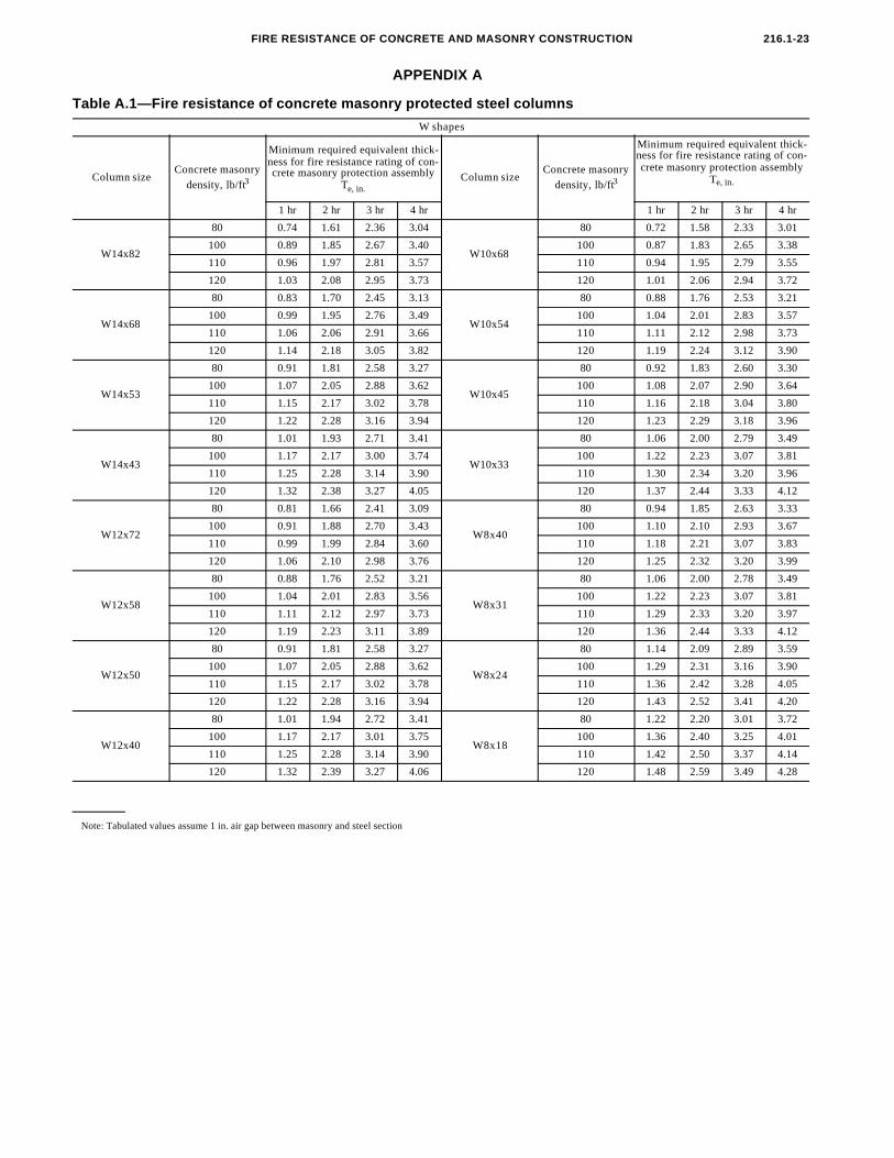
APPENDIX A
Table A.1—Fire resistance of concrete masonry protected steel columns
W shapes
Column sizeConcrete masonry
density, lb/ft3
Minimum required equivalent thick-ness for fire resistance rating of con-crete masonry protection assembly
Te, in.Column size
Concrete masonry
density, lb/ft3
Minimum required equivalent thick-ness for fire resistance rating of con-crete masonry protection assembly
Te, in.
1 hr 2 hr 3 hr 4 hr 1 hr 2 hr 3 hr 4 hr
W14x82
80 0.74 1.61 2.36 3.04
W10x68
80 0.72 1.58 2.33 3.01
100 0.89 1.85 2.67 3.40 100 0.87 1.83 2.65 3.38
110 0.96 1.97 2.81 3.57 110 0.94 1.95 2.79 3.55
120 1.03 2.08 2.95 3.73 120 1.01 2.06 2.94 3.72
W14x68
80 0.83 1.70 2.45 3.13
W10x54
80 0.88 1.76 2.53 3.21
100 0.99 1.95 2.76 3.49 100 1.04 2.01 2.83 3.57
110 1.06 2.06 2.91 3.66 110 1.11 2.12 2.98 3.73
120 1.14 2.18 3.05 3.82 120 1.19 2.24 3.12 3.90
W14x53
80 0.91 1.81 2.58 3.27
W10x45
80 0.92 1.83 2.60 3.30
100 1.07 2.05 2.88 3.62 100 1.08 2.07 2.90 3.64
110 1.15 2.17 3.02 3.78 110 1.16 2.18 3.04 3.80
120 1.22 2.28 3.16 3.94 120 1.23 2.29 3.18 3.96
W14x43
80 1.01 1.93 2.71 3.41
W10x33
80 1.06 2.00 2.79 3.49
100 1.17 2.17 3.00 3.74 100 1.22 2.23 3.07 3.81
110 1.25 2.28 3.14 3.90 110 1.30 2.34 3.20 3.96
120 1.32 2.38 3.27 4.05 120 1.37 2.44 3.33 4.12
W12x72
80 0.81 1.66 2.41 3.09
W8x40
80 0.94 1.85 2.63 3.33
100 0.91 1.88 2.70 3.43 100 1.10 2.10 2.93 3.67
110 0.99 1.99 2.84 3.60 110 1.18 2.21 3.07 3.83
120 1.06 2.10 2.98 3.76 120 1.25 2.32 3.20 3.99
W12x58
80 0.88 1.76 2.52 3.21
W8x31
80 1.06 2.00 2.78 3.49
100 1.04 2.01 2.83 3.56 100 1.22 2.23 3.07 3.81
110 1.11 2.12 2.97 3.73 110 1.29 2.33 3.20 3.97
120 1.19 2.23 3.11 3.89 120 1.36 2.44 3.33 4.12
W12x50
80 0.91 1.81 2.58 3.27
W8x24
80 1.14 2.09 2.89 3.59
100 1.07 2.05 2.88 3.62 100 1.29 2.31 3.16 3.90
110 1.15 2.17 3.02 3.78 110 1.36 2.42 3.28 4.05
120 1.22 2.28 3.16 3.94 120 1.43 2.52 3.41 4.20
W12x40
80 1.01 1.94 2.72 3.41
W8x18
80 1.22 2.20 3.01 3.72
100 1.17 2.17 3.01 3.75 100 1.36 2.40 3.25 4.01
110 1.25 2.28 3.14 3.90 110 1.42 2.50 3.37 4.14
120 1.32 2.39 3.27 4.06 120 1.48 2.59 3.49 4.28
Note: Tabulated values assume 1 in. air gap between masonry and steel section
ACI STANDARD216.1-24
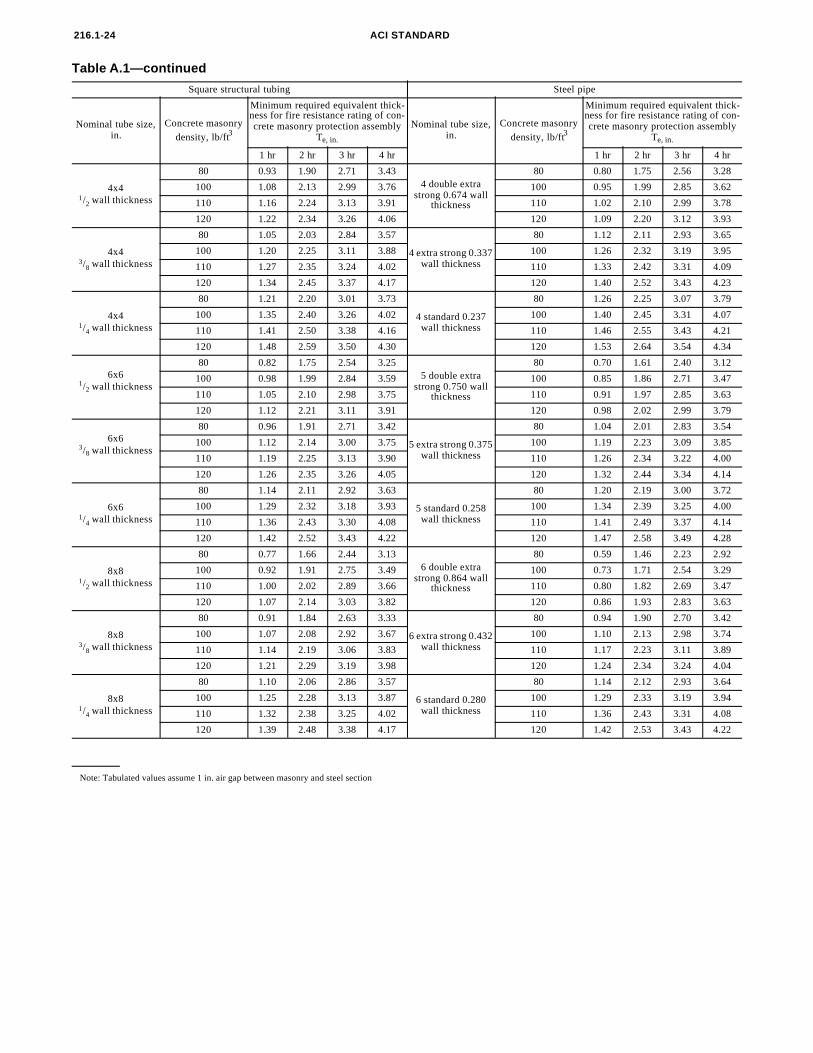
Note: Tabulated values assume 1 in. air gap between masonry and steel section
Table A.1—continued
Square structural tubing Steel pipe
Nominal tube size, in.
Concrete masonry
density, lb/ft3
Minimum required equivalent thick-ness for fire resistance rating of con-crete masonry protection assembly
Te, in.
Nominal tube size, in.
Concrete masonry
density, lb/ft3
Minimum required equivalent thick-ness for fire resistance rating of con-crete masonry protection assembly
Te, in.
1 hr 2 hr 3 hr 4 hr 1 hr 2 hr 3 hr 4 hr
4x41/2 wall thickness
80 0.93 1.90 2.71 3.434 double extra
strong 0.674 wall thickness
80 0.80 1.75 2.56 3.28
100 1.08 2.13 2.99 3.76 100 0.95 1.99 2.85 3.62
110 1.16 2.24 3.13 3.91 110 1.02 2.10 2.99 3.78
120 1.22 2.34 3.26 4.06 120 1.09 2.20 3.12 3.93
4x43/8 wall thickness
80 1.05 2.03 2.84 3.57
4 extra strong 0.337 wall thickness
80 1.12 2.11 2.93 3.65
100 1.20 2.25 3.11 3.88 100 1.26 2.32 3.19 3.95
110 1.27 2.35 3.24 4.02 110 1.33 2.42 3.31 4.09
120 1.34 2.45 3.37 4.17 120 1.40 2.52 3.43 4.23
4x41/4 wall thickness
80 1.21 2.20 3.01 3.73
4 standard 0.237 wall thickness
80 1.26 2.25 3.07 3.79
100 1.35 2.40 3.26 4.02 100 1.40 2.45 3.31 4.07
110 1.41 2.50 3.38 4.16 110 1.46 2.55 3.43 4.21
120 1.48 2.59 3.50 4.30 120 1.53 2.64 3.54 4.34
6x61/2 wall thickness
80 0.82 1.75 2.54 3.255 double extra
strong 0.750 wall thickness
80 0.70 1.61 2.40 3.12
100 0.98 1.99 2.84 3.59 100 0.85 1.86 2.71 3.47
110 1.05 2.10 2.98 3.75 110 0.91 1.97 2.85 3.63
120 1.12 2.21 3.11 3.91 120 0.98 2.02 2.99 3.79
6x63/8 wall thickness
80 0.96 1.91 2.71 3.42
5 extra strong 0.375 wall thickness
80 1.04 2.01 2.83 3.54
100 1.12 2.14 3.00 3.75 100 1.19 2.23 3.09 3.85
110 1.19 2.25 3.13 3.90 110 1.26 2.34 3.22 4.00
120 1.26 2.35 3.26 4.05 120 1.32 2.44 3.34 4.14
6x61/4 wall thickness
80 1.14 2.11 2.92 3.63
5 standard 0.258 wall thickness
80 1.20 2.19 3.00 3.72
100 1.29 2.32 3.18 3.93 100 1.34 2.39 3.25 4.00
110 1.36 2.43 3.30 4.08 110 1.41 2.49 3.37 4.14
120 1.42 2.52 3.43 4.22 120 1.47 2.58 3.49 4.28
8x81/2 wall thickness
80 0.77 1.66 2.44 3.136 double extra
strong 0.864 wall thickness
80 0.59 1.46 2.23 2.92
100 0.92 1.91 2.75 3.49 100 0.73 1.71 2.54 3.29
110 1.00 2.02 2.89 3.66 110 0.80 1.82 2.69 3.47
120 1.07 2.14 3.03 3.82 120 0.86 1.93 2.83 3.63
8x83/8 wall thickness
80 0.91 1.84 2.63 3.33
6 extra strong 0.432 wall thickness
80 0.94 1.90 2.70 3.42
100 1.07 2.08 2.92 3.67 100 1.10 2.13 2.98 3.74
110 1.14 2.19 3.06 3.83 110 1.17 2.23 3.11 3.89
120 1.21 2.29 3.19 3.98 120 1.24 2.34 3.24 4.04
8x81/4 wall thickness
80 1.10 2.06 2.86 3.57
6 standard 0.280 wall thickness
80 1.14 2.12 2.93 3.64
100 1.25 2.28 3.13 3.87 100 1.29 2.33 3.19 3.94
110 1.32 2.38 3.25 4.02 110 1.36 2.43 3.31 4.08
120 1.39 2.48 3.38 4.17 120 1.42 2.53 3.43 4.22
FIRE RESISTANCE OF CONCRETE AND MASONRY CONSTRUCTION 216.1-25
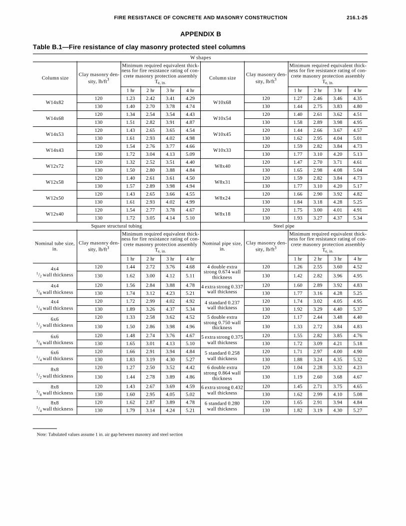
APPENDIX B
Table B.1—Fire resistance of clay masonry protected steel columns
W shapes
Column sizeClay masonry den-
sity, lb/ft3
Minimum required equivalent thick-ness for fire resistance rating of con-crete masonry protection assembly
Te, in.Column size
Clay masonry den-
sity, lb/ft3
Minimum required equivalent thick-ness for fire resistance rating of con-crete masonry protection assembly
Te, in.
1 hr 2 hr 3 hr 4 hr 1 hr 2 hr 3 hr 4 hr
W14x82120 1.23 2.42 3.41 4.29
W10x68120 1.27 2.46 3.46 4.35
130 1.40 2.70 3.78 4.74 130 1.44 2.75 3.83 4.80
W14x68120 1.34 2.54 3.54 4.43
W10x54120 1.40 2.61 3.62 4.51
130 1.51 2.82 3.91 4.87 130 1.58 2.89 3.98 4.95
W14x53120 1.43 2.65 3.65 4.54
W10x45120 1.44 2.66 3.67 4.57
130 1.61 2.93 4.02 4.98 130 1.62 2.95 4.04 5.01
W14x43120 1.54 2.76 3.77 4.66
W10x33120 1.59 2.82 3.84 4.73
130 1.72 3.04 4.13 5.09 130 1.77 3.10 4.20 5.13
W12x72120 1.32 2.52 3.51 4.40
W8x40120 1.47 2.70 3.71 4.61
130 1.50 2.80 3.88 4.84 130 1.65 2.98 4.08 5.04
W12x58120 1.40 2.61 3.61 4.50
W8x31120 1.59 2.82 3.84 4.73
130 1.57 2.89 3.98 4.94 130 1.77 3.10 4.20 5.17
W12x50120 1.43 2.65 3.66 4.55
W8x24120 1.66 2.90 3.92 4.82
130 1.61 2.93 4.02 4.99 130 1.84 3.18 4.28 5.25
W12x40120 1.54 2.77 3.78 4.67
W8x18120 1.75 3.00 4.01 4.91
130 1.72 3.05 4.14 5.10 130 1.93 3.27 4.37 5.34
Square structural tubing Steel pipe
Nominal tube size, in.
Clay masonry den-sity, lb/ft3
Minimum required equivalent thick-ness for fire resistance rating of con-crete masonry protection assembly
Te, in.
Nominal pipe size, in.
Clay masonry den-sity, lb/ft3
Minimum required equivalent thick-ness for fire resistance rating of con-crete masonry protection assembly
Te, in.
1 hr 2 hr 3 hr 4 hr 1 hr 2 hr 3 hr 4 hr
4x41/2 wall thickness
120 1.44 2.72 3.76 4.68 4 double extra strong 0.674 wall
thickness
120 1.26 2.55 3.60 4.52
130 1.62 3.00 4.12 5.11 130 1.42 2.82 3.96 4.95
4x43/8 wall thickness
120 1.56 2.84 3.88 4.78 4 extra strong 0.337 wall thickness
120 1.60 2.89 3.92 4.83
130 1.74 3.12 4.23 5.21 130 1.77 3.16 4.28 5.25
4x41/4 wall thickness
120 1.72 2.99 4.02 4.92 4 standard 0.237 wall thickness
120 1.74 3.02 4.05 4.95
130 1.89 3.26 4.37 5.34 130 1.92 3.29 4.40 5.37
6x61/2 wall thickness
120 1.33 2.58 3.62 4.52 5 double extra strong 0.750 wall
thickness
120 1.17 2.44 3.48 4.40
130 1.50 2.86 3.98 4.96 130 1.33 2.72 3.84 4.83
6x63/8 wall thickness
120 1.48 2.74 3.76 4.67 5 extra strong 0.375 wall thickness
120 1.55 2.82 3.85 4.76
130 1.65 3.01 4.13 5.10 130 1.72 3.09 4.21 5.18
6x61/4 wall thickness
120 1.66 2.91 3.94 4.84 5 standard 0.258 wall thickness
120 1.71 2.97 4.00 4.90
130 1.83 3.19 4.30 5.27 130 1.88 3.24 4.35 5.32
8x81/2 wall thickness
120 1.27 2.50 3.52 4.42 6 double extra strong 0.864 wall
thickness
120 1.04 2.28 3.32 4.23
130 1.44 2.78 3.89 4.86 130 1.19 2.60 3.68 4.67
8x83/8 wall thickness
120 1.43 2.67 3.69 4.59 6 extra strong 0.432 wall thickness
120 1.45 2.71 3.75 4.65
130 1.60 2.95 4.05 5.02 130 1.62 2.99 4.10 5.08
8x81/4 wall thickness
120 1.62 2.87 3.89 4.78 6 standard 0.280 wall thickness
120 1.65 2.91 3.94 4.84
130 1.79 3.14 4.24 5.21 130 1.82 3.19 4.30 5.27
Note: Tabulated values assume 1 in. air gap between masonry and steel section

ACI STANDARD216.1-26
APPENDIX C
A. This selected list gives practical conversion factors of units found in concrete technology. The reference sources for information on SI units and more exact conversion factors are ASTM E 380 and E 621. Symbols of metric units are given in parentheses.
B. “E” indicates that the figure given is exact.C. One liter (cubic decimeter) equals 0.001 m 3 or 1000 cm 3.D. These equations convert one temperature reading to another and include the necessary scale corrections. To convert the differ ence in temperature from Fahrenheit degrees to
Celsius degrees, divide by 1.8 only, i.e., a change from 70 to 88 deg F represents a change of 18 deg F, or 18/1.8 = 10 deg C.
CONVERSION FACTORS—INCH-POUNDS TO SI (METRIC)A
To convert from to Multiply by
Length
inch millimeter (mm) 25.4EB
foot meter (m) 0.3048E
yard meter (m) 0.9144Emile (statute) kilometer (km) 1.609
Area
square inch square millimeter (mm2) 645.1
square foot square meter (m2) 0.0929
square yard square meter (m2) 0.8361
Volume (capacity)
ounce milliliters (mL) 29.57
gallon cubic meter (m3)C 0.003785
cubic inch cubic millimeter (mm3) 16390
cubic foot cubic meter (m3) 0.02832
cubic yard cubic meter (m3) 0.7646
Forcekilogram-force newton (N) 9.807
kip-force kilo newton (kN) 4.448pound-force newton (N) 4.448
Pressure or stress (force per area)
kilogram-force/square meter pascal (Pa) 9.807kip-force/square inch (ksi) megapascal (MPa) 6.895
newton/square meter (N/m2) pascal (Pa) 1.000E
pound-force/square foot pascal (Pa) 47.88pound-force/square inch (psi) kilopascal (kPa) 6.895
Bending moment or torqueinch-pound-force newton-meter (N²m) 0.1130foot-pound-force newton-meter (N²m) 1.356
meter-kilogram-force newton-meter (N²m) 9.807Mass
ounce-mass (avoirdupois) gram (g) 28.34
pound-mass (avoirdupois) kilogram (kg) 0.4536ton (metric) megagram (Mg) 1.000E
ton (short, 2000 lbm) kilogram (kg) 907.2
Mass per volume
pound-mass/cubic foot kilogram/cubic meter (kg/m3) 16.02
pound-mass/cubic yard kilogram/cubic meter (kg/m3) 0.5933
pound-mass/gallon kilogram/cubic meter (kg/m3) 119.8
TemperatureD
degrees Fahrenheit (F) degrees Celsius (C) tC = (tF - 32)/1.8
degrees Celsius (C) degrees Fahrenheit (F) tF = 1.8tC + 32