21st century radios.ppt - g4jnt
TRANSCRIPT
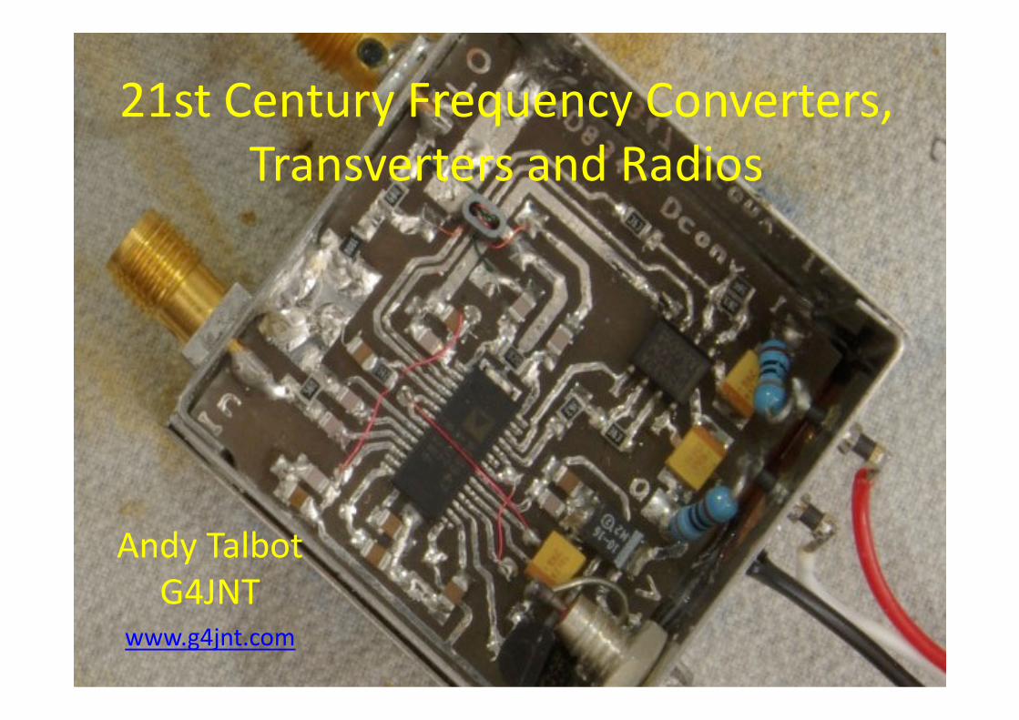
21st Century Frequency Converters,
Transverters and Radios
Andy Talbot
G4JNTwww.g4jnt.com

What we used to build
Replace with minimum
tuning, wideband
integrated solutions

Background
• The mobile phone and modern RF industry
give us nice RF chips - for peanuts
• Frequency Converters and Synthesizers
– AD8347 £15
• 0.8 – 2.6GHz Downconverter,• 0.8 – 2.6GHz Downconverter,
• 60dB gain and AGC.
– AD8346 Upconverter £12
– LMX2326 Fixed synth – 2.6GHz £2.93 (RS)
– LMX2470 2.5GHz FractN synth, £6

Frequency Conversion
• Single Chip Up and Down convert.
• 800 – 2600MHz – but will usually work higher
– Other chips cover HF to UHF
• IF DC – 50MHz• IF DC – 50MHz
– Baseband or IF
• Low RF input power -15dBm
– Linearity similar to diode mixers
• Downconverter - 60dB DC gain control

1.3 and 2.3GHz Tx Source
Direct upconversion
from I/Q
baseband input
Beacon or linear
transmitter

Baseband processing
• Replacement for the Transceiver
• SDR Software, Soundcard input / output
– Limited Tuning over few tens of kHz
– WinRad, Rocky, SDRadio......– WinRad, Rocky, SDRadio......
– Filters galore
• Standalone hardware
– Kit/Module with DSP chip, audio amp – SDR2GO
• Polyphase / Audio 90 degree networks

Direct Conversion Receiver 1.3GHz, 2.3GHz, ( 3400MHz)

Direct Conversion Software
Plenty of Receiver
software.
Typically allows
tuning ±24kHz
Not much for Tx.
G3PLX basic prog G3PLX basic prog
mic input, IQ out,
±800Hz tuning. + AM/FM
USB / Bluetooth
Headset Mic
Input

Rx & Tx standalone (no PC)
SDR2GO – Baseband
I/Q Mod/Demod
(Si570 control not
used)
SSB with mic or line
input
On-Off carrier (with
audio sidetone)

The Downside
• Direct Conversion suffers from input
rectification.
– GSM, 3G, DECT , WLAN
– MASSIVE pulsed signals in local environment– MASSIVE pulsed signals in local environment
• Input filtering
• Ok for use out in field,
– Beacon monitor works OK –

OR the Conventional Route
IQ Conversion to RF & 28MHz Transceiver
The AD8346 and ’47 work with IFs to >50MHz
IQ network for conventional transverter design
no need for serious image filtering. no need for serious image filtering.
Off-the-shelf Minicircuits PSCQ-2-40 quad hybrid 23 – 40MHz
35dB sideband rejection
LOW IF – 100kHz to MHz. RC tuned 2nd LO

Hi/Low Pass
90⁰ phase
shifter

Local Oscillators
Fixed Frequency Synthesizer
Ideal for
Transverter LOs Transverter LOs LMX2326 to 2.6GHz
OR
AD41020 to 18GHz

Integer N• LMX2326 is typical – and getting on a bit now!
• 100MHz to 2.6GHz input
– R divider (R = 3 to 16383)
– N divider (N = 32 to 262175)
• Some flexibility for odd freqs• Some flexibility for odd freqs
• Fout = Fref * N / R
– VCO Drive 0 – 5V,
– Loop filter ~ 3 Caps, 2 Rs
– LM6211 opamp Vtune > Vcc

RS232 programming

Continuous Tuning
• Transverters for full tuning at IF
– so a fixed LO is no problem
• Direct Conversion or fixed IF receivers give at • Direct Conversion or fixed IF receivers give at
most a few kHz, or no tuning at all.
– So.....
– We Need a tuneable LO at microwaves

KISS• Pull the synthesizer reference input
– Typical || resonant at 10MHz will pull 30 –
50ppm depending on wanted stability.
– 100kHz at 2.3GHz, 400kHz at 10g
– Ceramic resonator even more !– Ceramic resonator even more !
– Play with R and N values. Any surplus crystal.
• ‘Intelligent’ Freq counter display on Xtal freq.
• Low IF at 100kHz, RC tuned LO.
• These are NOT LOCKED ! IC202 equivalent• Use DDS as reference. Locked, but not too clean

Nominal Centre
Freq 2320.9 MHz
Nominal Crystal 10 MHz
Pulling Range 40 +/- ppm
Approx Fref 454 kHz
Actual R 22
Actual N 5106
Fmin 2320.8163 MHz
Fmax 2321.0019 MHz
Delta 185.67 kHz

Fractional N Synthesizer
• Generate directly at GHz
– LMX2470 to 2.5GHz, LMX2487 to 6GHz
• Locked to Master Reference input
• Tiny step size – few Hz• Tiny step size – few Hz
• Fout = Fref / R * (N + F / D)
– Let R = 1 for 10MHz ref (or X2)
– D = 1000000 for 10Hz steps
– Loop BW 30 - 100kHz for low cost VCO

LMX2470 Synth PCB

Data Modes
• Set tuning grid to the tone spacing
– JT65c 10.7666Hz
– JT4g 315Hz
• Send codes to change F register• Send codes to change F register
• Standalone Beacon Source
– Faster switching than RDDS
– Accurate tone spacing at 10GHz and up

Phase noise and Spurii
• Always a problem with synths – isn’t it?
– BUT .... Is phase really an issue ?
– We want narrowband signalling.
• Any modern synth with Fref > 50kHz and loop BW >
8kHz will “sound clean”, 8kHz will “sound clean”,
• Unnoticed on SSB or audio tones.
– Strong signals / other stations nearby
– Close in spurs typical -60 to -80dBc,
– Big effort needed with contest stations
– Make sure the reference input is clean

5Hz tuning grid at 2320MHz

VCOs
• Minicircuits packaged –
– low(ish) cost
– Known spec, MHz/V
• Surplus
– Old ‘Brick’ sources excellent 1.4 – 1.8GHz typical
– Multipliers that are easily retuned
• Discrete
– Some good designs wanted
– Cavity / coax / stripline / LC

LMX2487 + ‘Brick’ LO at 5.76GHz
Discrete Spurii are on the
10MHz GPSDO reference
input.

The SMALL PRINT
• Surface Mount small components
– SOIC 1.27mm pin spacing
– TSSOP QFP– Thin-Shrink Small Outline Package, Quad Flat Pack) – Thin-Shrink Small Outline Package, Quad Flat Pack)
• 0.64mm pin spacing
• Easily hand soldered (flux and wipe)
– QFN (Quad Flat No leads)
• LMX2470/ 87
• The PIN ‘0’ bottom pad.

Soldering
• Decent iron with small bit
– Higher temp, solder flows better
• Separate flux
– Prevents bridging
• Solder braid
– Just In case
• Use leaded solder
– Its going to be around for a long time yet

The Upside
• Robust chips
– A lot better than earlier devices
– Better static protection
– Designed for higher soldering temperature– Designed for higher soldering temperature
– Never damaged one from handling – and that
includes removal twice!

PCBs aren’t Compulsory !
“Rats Nest“
Construction,
Please , NOT
“Birds Nest”

But PCBs do make life easier...
• Homebrew
• Laser printer and Press-N-Peel OR
• Acetate and UV light box
• Both will cope with TSSOP (0.64mm pin • Both will cope with TSSOP (0.64mm pin
spacing)
• P-n-P OK with QFP (0.5mm pad spacing) for
fract N synths
– This is probably about the limit ?

Homebrew PCBs Pin 0

Other Skills• Synth chips want serial programming –
– PIC interface
• Plenty of code already out there to do the job
– GET or make a PIC programmer and at least be
able to blow your own devices from published able to blow your own devices from published
code.
• BETTER STILL
– Assemble code from published sources
– Do your own customisation, callsigns, frequencies

‘JNT PIC “Operating System”
• Each synth chip needs custom serial
programming
• Small 8-pin 12F629 PIC with standardised set
of connectionsof connections
• RS232 serial programming
– instant self-boot at turn on
• Easy access to synth-chip registers
• Some customised driver code

Driver Progs
Talk to PIC OS. /
Synth on Serial
Interface

Questions