22-mm diameter and thermally enhanced three-phase
TRANSCRIPT
DRV10974
180° Sensorless Sinusoidal
PWM
FG
4.4 V to 18 V
V M
WUFR
Current Limit
Accel Profile
Lead Angle
VCP
1TIDUDW3–March 2018Submit Documentation Feedback
Copyright © 2018, Texas Instruments Incorporated
22-mm Diameter and Thermally Enhanced Three-Phase BLDC Motor DriverReference Design
TI Designs: TIDA-0161922-mm Diameter and Thermally Enhanced Three-PhaseBLDC Motor Driver Reference Design
DescriptionThe TIDA-01619 provides a three-phase brushless DC(BLDC) motor driver solution for systems with anoperating range from 4.4 V to 18 V. This designfeatures the DRV10974 motor driver with the ability toadd MCU for closedloop speed control. TheDRV10974 offers sensorless commutation with noneed of hall sensors, only 6 external passivecomponents allow for a low-cost solution and an 180°sinusoidal commutation system allows optimalefficiency and low acoustics. This reference designprovides guidelines in 22-mm diameter board designand thermal enhancement with a double-layer layoutand 2-oz copper thickness.
Resources
TIDA-01619 Design FolderDRV10974 Product Folder
ASK Our E2E™ Experts
Applications• Server Fans• Desktop PC Fans• BLDC Motor Drives
Features• Thermally Enhanced: 2 Layers and 2-oz Copper
Thickness• Small Form Factor: 22-mm Diameter• Input Voltage Range: 4.4 V to 18 V• Phase Drive Current: 1-A Continuous (1.5-A Peak)• 180° Sinusoidal Commutation for Optimal Acoustic
Performance• Lead Angle Configurable With External Resistor• Soft Start and Resistor-Configurable Acceleration
Profile• Built-in Current Sense to Eliminate External
Current-Sense Resistor• No Motor Center Tap Required• Simple User Interface:
– One-Pin Configuration for Start-up– PWM Input Designates Magnitude of Voltage
Applied to Motor– Open-Drain FG Output Provides Speed
Feedback– Pin for Forward and Reverse Control
• Fully Protected:– Motor-Lock Detect and Restart– Overcurrent, Short-Circuit, Overtemperature,
Undervoltage
System Description www.ti.com
2 TIDUDW3–March 2018Submit Documentation Feedback
Copyright © 2018, Texas Instruments Incorporated
22-mm Diameter and Thermally Enhanced Three-Phase BLDC Motor DriverReference Design
An IMPORTANT NOTICE at the end of this TI reference design addresses authorized use, intellectual property matters and otherimportant disclaimers and information.
1 System DescriptionThis reference design is a small, thermally enhanced, three-phase sensorless sinusoidal motor driver forbrushless DC (BLDC) motors. The DRV10974 can support a range of voltage from 4.4 V to 18 V as inputand a phase current of 1-A continuous and 1.5-A peak.
The PCB is designed for small space restriction and high temperature ambient areas. With a 22-mmdiameter, the PCB is small to fit on server fans, desktop fans, and other small BLDC motors. The designalso considers heat dissipation with a 2-oz copper thickness, double layers, and multiple vias for athermally enhanced design.
The PWM pin in the DRV10974 allows to control speed by changing the duty cycle. The FG pin providesspeed feedback and the FR pin for forward and reverse control. With resistors on pins CS, ADV, andRMP, one can configure current limit, lead angle, and acceleration profile, respectively.
With full protection, an integrated BLDC motor driver, and an easy-to-use system, this reference design isbest for small and thermal challenged applications.
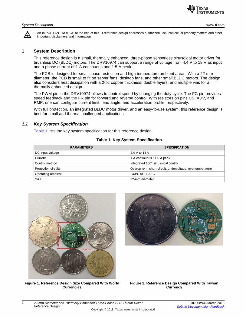
1.1 Key System SpecificationTable 1 lists the key system specification for this reference design.
Table 1. Key System Specification
PARAMETERS SPECIFICATIONDC input voltage 4.4 V to 18 VCurrent 1 A continuous / 1.5 A peakControl method Integrated 180° sinusoidal controlProtection circuits Overcurrent, short-circuit, undervoltage, overtemperatureOperating ambient –40°C to +120°CSize 22-mm diameter
Figure 1. Reference Design Size Compared With WorldCurrencies
Figure 2. Reference Design Compared With TaiwanCurrency
DRV10974
180° Sensorless Sinusoidal
PWM
FG
4.4 V to 18 V
V M
WUFR
Current Limit
Accel Profile
Lead Angle
VCP
www.ti.com System Overview
3TIDUDW3–March 2018Submit Documentation Feedback
Copyright © 2018, Texas Instruments Incorporated
22-mm Diameter and Thermally Enhanced Three-Phase BLDC Motor DriverReference Design
2 System Overview
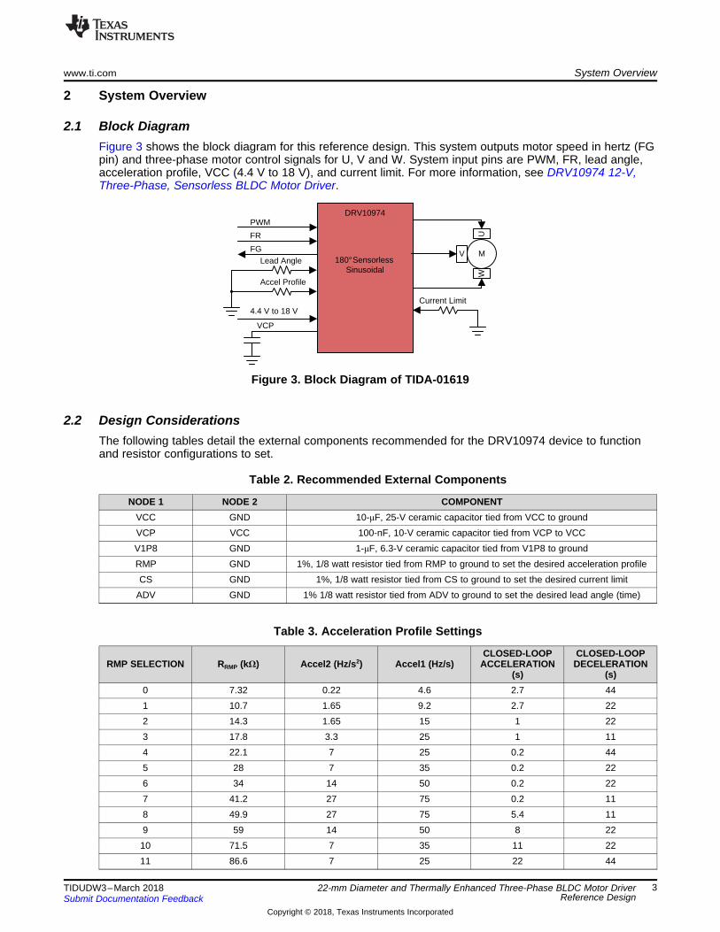
2.1 Block DiagramFigure 3 shows the block diagram for this reference design. This system outputs motor speed in hertz (FGpin) and three-phase motor control signals for U, V and W. System input pins are PWM, FR, lead angle,acceleration profile, VCC (4.4 V to 18 V), and current limit. For more information, see DRV10974 12-V,Three-Phase, Sensorless BLDC Motor Driver.
Figure 3. Block Diagram of TIDA-01619
2.2 Design ConsiderationsThe following tables detail the external components recommended for the DRV10974 device to functionand resistor configurations to set.
Table 2. Recommended External Components
NODE 1 NODE 2 COMPONENTVCC GND 10-μF, 25-V ceramic capacitor tied from VCC to groundVCP VCC 100-nF, 10-V ceramic capacitor tied from VCP to VCCV1P8 GND 1-μF, 6.3-V ceramic capacitor tied from V1P8 to groundRMP GND 1%, 1/8 watt resistor tied from RMP to ground to set the desired acceleration profileCS GND 1%, 1/8 watt resistor tied from CS to ground to set the desired current limit
ADV GND 1% 1/8 watt resistor tied from ADV to ground to set the desired lead angle (time)
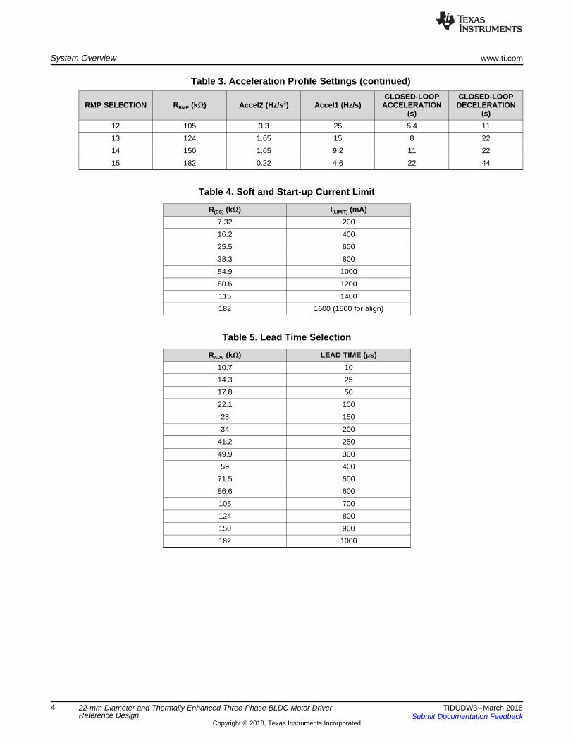
Table 3. Acceleration Profile Settings
RMP SELECTION RRMP (kΩ) Accel2 (Hz/s2) Accel1 (Hz/s)CLOSED-LOOP
ACCELERATION(s)
CLOSED-LOOPDECELERATION
(s)0 7.32 0.22 4.6 2.7 441 10.7 1.65 9.2 2.7 222 14.3 1.65 15 1 223 17.8 3.3 25 1 114 22.1 7 25 0.2 445 28 7 35 0.2 226 34 14 50 0.2 227 41.2 27 75 0.2 118 49.9 27 75 5.4 119 59 14 50 8 2210 71.5 7 35 11 2211 86.6 7 25 22 44
System Overview www.ti.com
4 TIDUDW3–March 2018Submit Documentation Feedback
Copyright © 2018, Texas Instruments Incorporated
22-mm Diameter and Thermally Enhanced Three-Phase BLDC Motor DriverReference Design
Table 3. Acceleration Profile Settings (continued)
RMP SELECTION RRMP (kΩ) Accel2 (Hz/s2) Accel1 (Hz/s)CLOSED-LOOP
ACCELERATION(s)
CLOSED-LOOPDECELERATION
(s)12 105 3.3 25 5.4 1113 124 1.65 15 8 2214 150 1.65 9.2 11 2215 182 0.22 4.6 22 44
Table 4. Soft and Start-up Current Limit
R(CS) (kΩ) I(LIMIT) (mA)7.32 20016.2 40025.5 60038.3 80054.9 100080.6 1200115 1400182 1600 (1500 for align)
Table 5. Lead Time Selection
RADV (kΩ) LEAD TIME (µs)10.7 1014.3 2517.8 5022.1 10028 15034 200
41.2 25049.9 30059 400
71.5 50086.6 600105 700124 800150 900182 1000
Top
Bottom
3D Traces or Vias Polygon Pours Real
ADV1
FR2
FG3
PWM4
V1P85
RMP6
GND7
CS8
PGND10
W13
V12
U11
VCC14
VCP15
GND16
NC9
PAD17
U1
DRV10974PWP
ADV
CS
RMP
PWM
FG
GND
VCC
GND
U
V
W
1µFC2
10µFC3
GND
V1P8
ADV RMP CS
GND GND GND
59.0k
R1
FG
SPEED
VCP
VCC
FR
0.1µF
C1
42.2k
R2
140k
R3
10.0k
R5
3.3V
www.ti.com System Overview
5TIDUDW3–March 2018Submit Documentation Feedback
Copyright © 2018, Texas Instruments Incorporated
22-mm Diameter and Thermally Enhanced Three-Phase BLDC Motor DriverReference Design
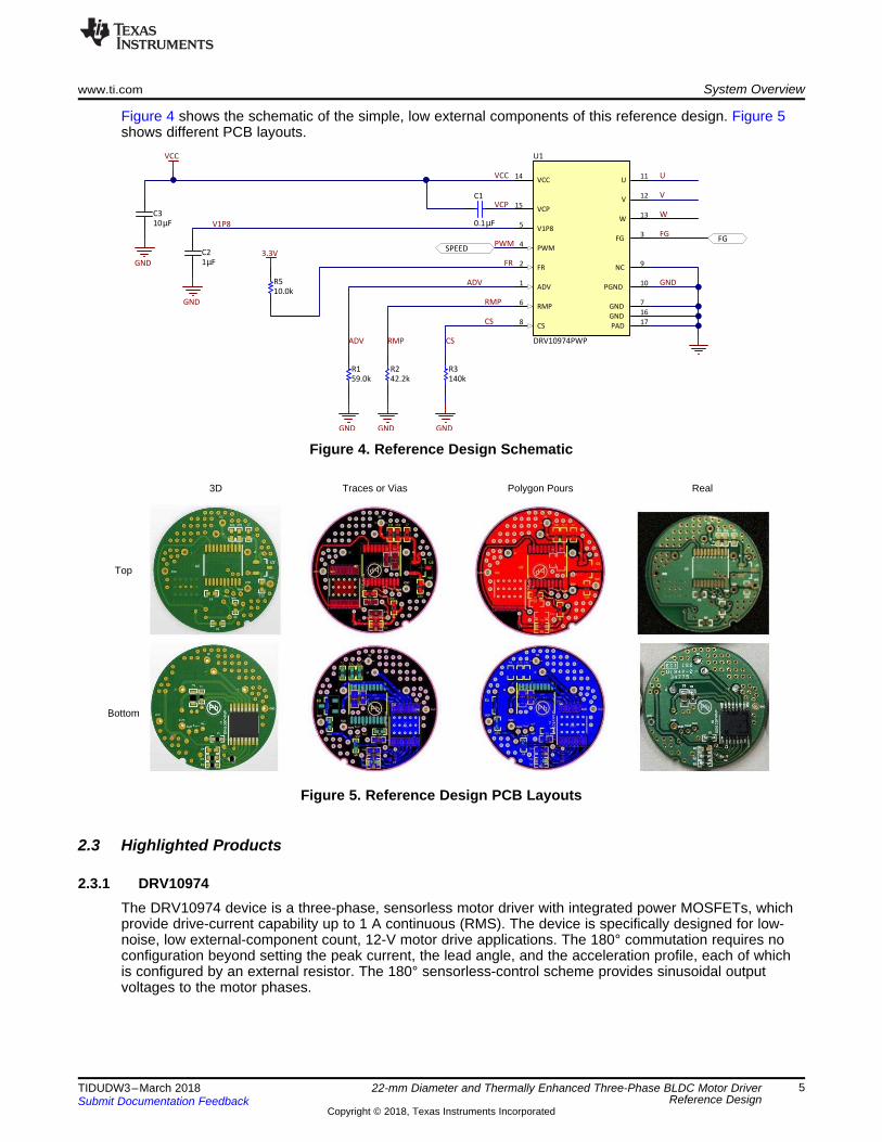
Figure 4 shows the schematic of the simple, low external components of this reference design. Figure 5shows different PCB layouts.
Figure 4. Reference Design Schematic
Figure 5. Reference Design PCB Layouts
2.3 Highlighted Products
2.3.1 DRV10974The DRV10974 device is a three-phase, sensorless motor driver with integrated power MOSFETs, whichprovide drive-current capability up to 1 A continuous (RMS). The device is specifically designed for low-noise, low external-component count, 12-V motor drive applications. The 180° commutation requires noconfiguration beyond setting the peak current, the lead angle, and the acceleration profile, each of whichis configured by an external resistor. The 180° sensorless-control scheme provides sinusoidal outputvoltages to the motor phases.
TJ
JCTC
VIA
Cu
Cu Cu
Cu
Cu
Cu
FR4
FR4
FR4
FR4
FR4
FR4
Cu
Cu
Cu
Cu
SA SA
SA SASASASA
Cu
Cu
Cu
Cu
Cu
Cu
Cu
FR4
FR4
FR4
FR4
FR4
FR4
SA
SA SA
Junction Temperature
Ambient Air Temperature(TA)
� �JA junction ambientT T Power DissipationT � u
System Overview www.ti.com
6 TIDUDW3–March 2018Submit Documentation Feedback
Copyright © 2018, Texas Instruments Incorporated
22-mm Diameter and Thermally Enhanced Three-Phase BLDC Motor DriverReference Design
Interfacing to the DRV10974 device is simple and intuitive. The DRV10974 device receives a PWM inputthat it uses to control the speed of the motor. The duty cycle of the PWM input is used to determine themagnitude of the voltage applied to the motor. The resulting motor speed can be monitored on the FG pin.The FR pin is used to control the direction of rotation for the motor. The acceleration ramp rate iscontrolled by the RMP pin. The current limit is controlled by a resistor on the CS pin. The lead angle iscontrolled by a resistor on the ADV pin. When the motor is not spinning, a low-power mode turns offunused circuits to conserve power.
The DRV10974 device features extensive protection and fault-detect mechanisms to ensure reliableoperation. The device provides overcurrent protection without the requirement for an external current-sense resistor. Rotorlock detect uses several methods to reliably determine when the rotor stops spinningunexpectedly. The device provides additional protection for undervoltage lockout (UVLO), for thermalshutdown, and for phase short circuit (phase to phase, phase to ground, phase to supply).
2.4 System Design Theory
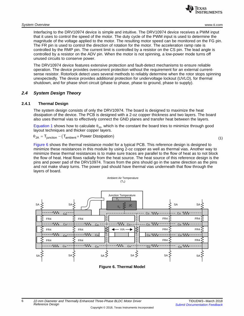
2.4.1 Thermal DesignThe system design consists of only the DRV10974. The board is designed to maximize the heatdissipation of the device. The PCB is designed with a 2-oz copper thickness and two layers. The boardalso uses thermal vias to effectively connect the GND planes and transfer heat between the layers.
Equation 1 shows how to calculate θJA, which is the constant the board tries to minimize through goodlayout techniques and thicker copper layers.
(1)
Figure 6 shows the thermal resistance model for a typical PCB. This reference design is designed tominimize these resistances in this module by using 2-oz copper as well as thermal vias. Another way tominimize these thermal resistances is to make sure traces are parallel to the flow of heat as to not blockthe flow of heat. Heat flows radially from the heat source. The heat source of this reference design is thepins and power pad of the DRV10974. Traces from the pins should go in the same direction as the pinsand not make sharp turns. The power pad should have thermal vias underneath that flow through thelayers of board.
Figure 6. Thermal Model
www.ti.com System Overview
7TIDUDW3–March 2018Submit Documentation Feedback
Copyright © 2018, Texas Instruments Incorporated
22-mm Diameter and Thermally Enhanced Three-Phase BLDC Motor DriverReference Design
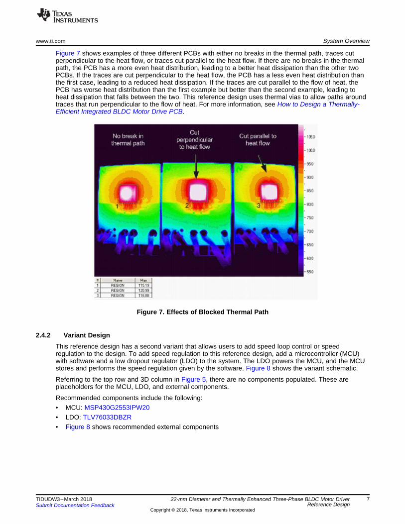
Figure 7 shows examples of three different PCBs with either no breaks in the thermal path, traces cutperpendicular to the heat flow, or traces cut parallel to the heat flow. If there are no breaks in the thermalpath, the PCB has a more even heat distribution, leading to a better heat dissipation than the other twoPCBs. If the traces are cut perpendicular to the heat flow, the PCB has a less even heat distribution thanthe first case, leading to a reduced heat dissipation. If the traces are cut parallel to the flow of heat, thePCB has worse heat distribution than the first example but better than the second example, leading toheat dissipation that falls between the two. This reference design uses thermal vias to allow paths aroundtraces that run perpendicular to the flow of heat. For more information, see How to Design a Thermally-Efficient Integrated BLDC Motor Drive PCB.
Figure 7. Effects of Blocked Thermal Path
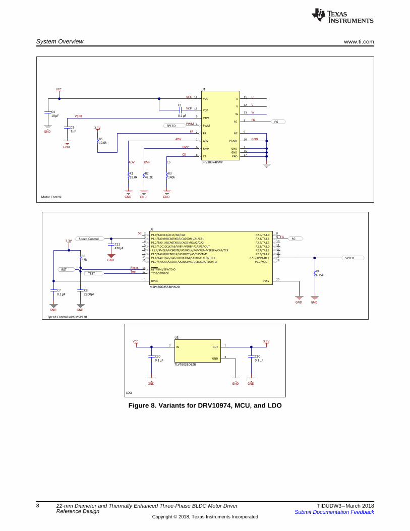
2.4.2 Variant DesignThis reference design has a second variant that allows users to add speed loop control or speedregulation to the design. To add speed regulation to this reference design, add a microcontroller (MCU)with software and a low dropout regulator (LDO) to the system. The LDO powers the MCU, and the MCUstores and performs the speed regulation given by the software. Figure 8 shows the variant schematic.
Referring to the top row and 3D column in Figure 5, there are no components populated. These areplaceholders for the MCU, LDO, and external components.
Recommended components include the following:• MCU: MSP430G2553IPW20• LDO: TLV76033DBZR• Figure 8 shows recommended external components
ADV1
FR2
FG3
PWM4
V1P85
RMP6
GND7
CS8
PGND10
W13
V12
U11
VCC14
VCP15
GND16
NC9
PAD17
U1
DRV10974PWP
ADV
CS
RMP
PWMFG
GND
VCC
GND
U
V
W
1µFC2
10µFC3
GND
V1P8
ADV RMP CS
GND GND GND
59.0kR1
FGSPEED
Motor Control
VCP
VCC
FR
0.1µF
C1
42.2kR2
140kR3
10.0kR5
3.3V
GND
FG
GND
Speed Control with MSP430
TESTRST
GND
3.3V
SPEED
470pFC11
GND
2200pFC8
4.75kR4
47kR6
DVCC1
P1.0/TA0CLK/ACLK/A0/CA02
P1.1/TA0.0/UCA0RXD/UCA0SOMI/A1/CA13
P1.2/TA0.1/UCA0TXD/UCA0SIMO/A2/CA24
P1.3/ADC10CLK/A3/VREF-/VEREF-/CA3/CAOUT5
P1.4/SMCLK/UCB0STE/UCA0CLK/A4/VREF+/VEREF+/CA4/TCK6
P1.5/TA0.0/UCB0CLK/UCA0STE/A5/CA5/TMS7
P2.0/TA1.08
P2.1/TA1.19
P2.2/TA1.110
P2.3/TA1.011
P2.4/TA1.212
P2.5/TA1.213
P1.6/TA0.1/A6/CA6/UCB0SOMI/UCB0SCL/TDI/TCLK14
P1.7/A7/CA7/CAOUT/UCB0SIMO/UCB0SDA/TDO/TDI15
RST/NMI/SBWTDIO16
TEST/SBWTCK17
P2.7/XOUT18
P2.6/XIN/TA0.119
DVSS20
U2
MSP430G2553IPW20
GND
ResetTest
FGSpeed Control
SC
0.1µFC7
IN2
OUT1
GND3
TLV76033DBZR
U3
0.1µFC20
GND GNDGND
VCC 3.3V
LDO
0.1µFC10
System Overview www.ti.com
8 TIDUDW3–March 2018Submit Documentation Feedback
Copyright © 2018, Texas Instruments Incorporated
22-mm Diameter and Thermally Enhanced Three-Phase BLDC Motor DriverReference Design
Figure 8. Variants for DRV10974, MCU, and LDO
WV
U
GND
FG
PWM
VCC
www.ti.com Hardware, Testing Requirements, and Test Results
9TIDUDW3–March 2018Submit Documentation Feedback
Copyright © 2018, Texas Instruments Incorporated
22-mm Diameter and Thermally Enhanced Three-Phase BLDC Motor DriverReference Design
3 Hardware, Testing Requirements, and Test Results
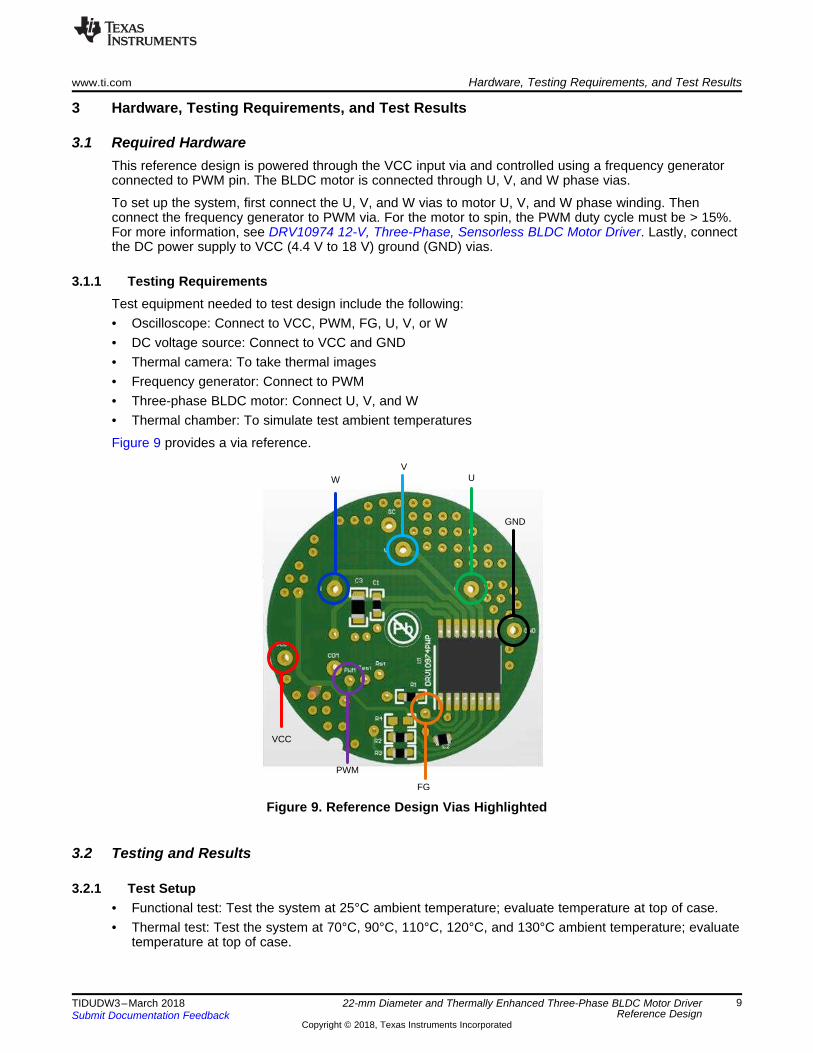
3.1 Required HardwareThis reference design is powered through the VCC input via and controlled using a frequency generatorconnected to PWM pin. The BLDC motor is connected through U, V, and W phase vias.
To set up the system, first connect the U, V, and W vias to motor U, V, and W phase winding. Thenconnect the frequency generator to PWM via. For the motor to spin, the PWM duty cycle must be > 15%.For more information, see DRV10974 12-V, Three-Phase, Sensorless BLDC Motor Driver. Lastly, connectthe DC power supply to VCC (4.4 V to 18 V) ground (GND) vias.
3.1.1 Testing RequirementsTest equipment needed to test design include the following:• Oscilloscope: Connect to VCC, PWM, FG, U, V, or W• DC voltage source: Connect to VCC and GND• Thermal camera: To take thermal images• Frequency generator: Connect to PWM• Three-phase BLDC motor: Connect U, V, and W• Thermal chamber: To simulate test ambient temperatures
Figure 9 provides a via reference.
Figure 9. Reference Design Vias Highlighted
3.2 Testing and Results
3.2.1 Test Setup• Functional test: Test the system at 25°C ambient temperature; evaluate temperature at top of case.• Thermal test: Test the system at 70°C, 90°C, 110°C, 120°C, and 130°C ambient temperature; evaluate
temperature at top of case.
Hardware, Testing Requirements, and Test Results www.ti.com
10 TIDUDW3–March 2018Submit Documentation Feedback
Copyright © 2018, Texas Instruments Incorporated
22-mm Diameter and Thermally Enhanced Three-Phase BLDC Motor DriverReference Design
3.2.2 Test Results
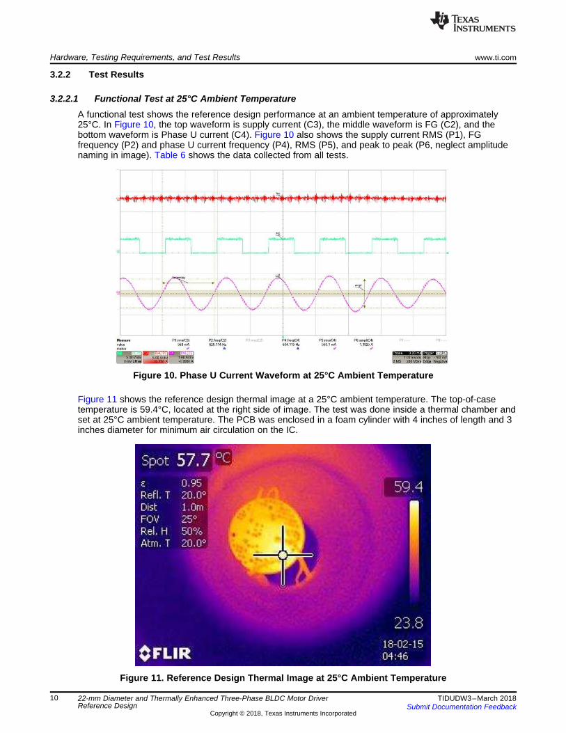
3.2.2.1 Functional Test at 25°C Ambient TemperatureA functional test shows the reference design performance at an ambient temperature of approximately25°C. In Figure 10, the top waveform is supply current (C3), the middle waveform is FG (C2), and thebottom waveform is Phase U current (C4). Figure 10 also shows the supply current RMS (P1), FGfrequency (P2) and phase U current frequency (P4), RMS (P5), and peak to peak (P6, neglect amplitudenaming in image). Table 6 shows the data collected from all tests.
Figure 10. Phase U Current Waveform at 25°C Ambient Temperature
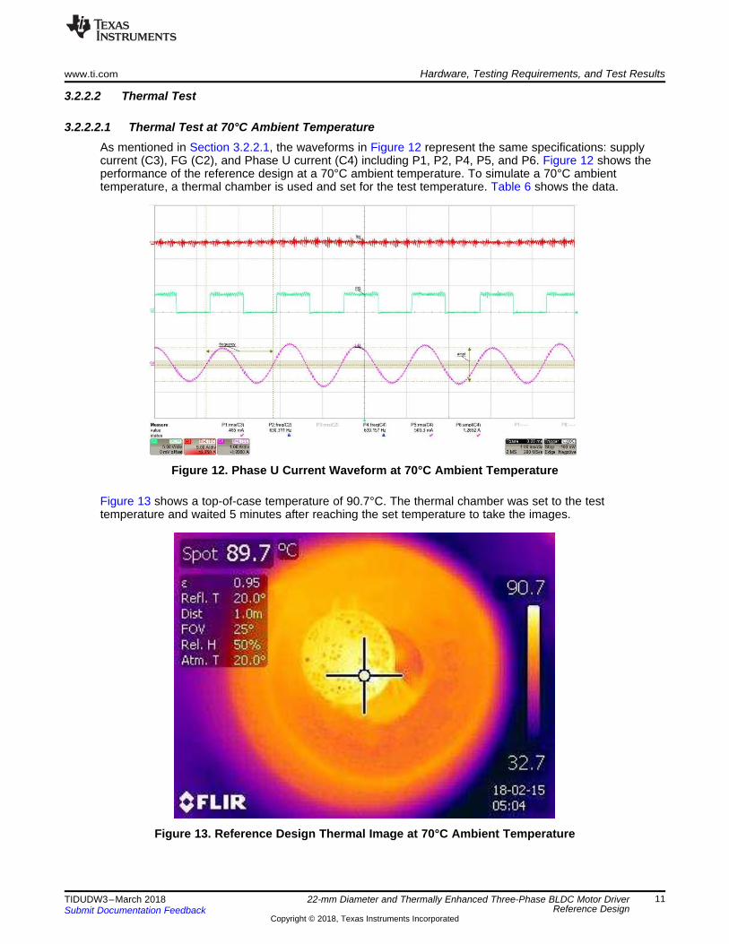
Figure 11 shows the reference design thermal image at a 25°C ambient temperature. The top-of-casetemperature is 59.4°C, located at the right side of image. The test was done inside a thermal chamber andset at 25°C ambient temperature. The PCB was enclosed in a foam cylinder with 4 inches of length and 3inches diameter for minimum air circulation on the IC.
Figure 11. Reference Design Thermal Image at 25°C Ambient Temperature
www.ti.com Hardware, Testing Requirements, and Test Results
11TIDUDW3–March 2018Submit Documentation Feedback
Copyright © 2018, Texas Instruments Incorporated
22-mm Diameter and Thermally Enhanced Three-Phase BLDC Motor DriverReference Design
3.2.2.2 Thermal Test
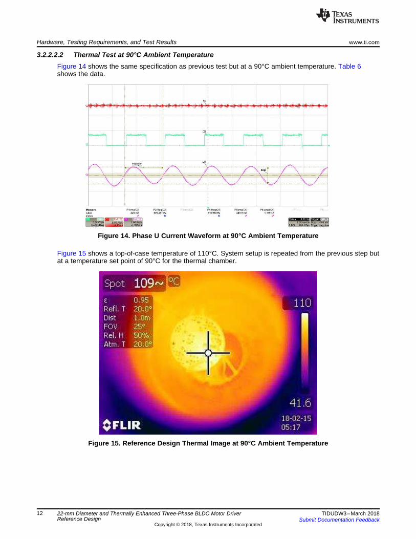
3.2.2.2.1 Thermal Test at 70°C Ambient TemperatureAs mentioned in Section 3.2.2.1, the waveforms in Figure 12 represent the same specifications: supplycurrent (C3), FG (C2), and Phase U current (C4) including P1, P2, P4, P5, and P6. Figure 12 shows theperformance of the reference design at a 70°C ambient temperature. To simulate a 70°C ambienttemperature, a thermal chamber is used and set for the test temperature. Table 6 shows the data.
Figure 12. Phase U Current Waveform at 70°C Ambient Temperature
Figure 13 shows a top-of-case temperature of 90.7°C. The thermal chamber was set to the testtemperature and waited 5 minutes after reaching the set temperature to take the images.
Figure 13. Reference Design Thermal Image at 70°C Ambient Temperature
Hardware, Testing Requirements, and Test Results www.ti.com
12 TIDUDW3–March 2018Submit Documentation Feedback
Copyright © 2018, Texas Instruments Incorporated
22-mm Diameter and Thermally Enhanced Three-Phase BLDC Motor DriverReference Design
3.2.2.2.2 Thermal Test at 90°C Ambient TemperatureFigure 14 shows the same specification as previous test but at a 90°C ambient temperature. Table 6shows the data.
Figure 14. Phase U Current Waveform at 90°C Ambient Temperature
Figure 15 shows a top-of-case temperature of 110°C. System setup is repeated from the previous step butat a temperature set point of 90°C for the thermal chamber.
Figure 15. Reference Design Thermal Image at 90°C Ambient Temperature
www.ti.com Hardware, Testing Requirements, and Test Results
13TIDUDW3–March 2018Submit Documentation Feedback
Copyright © 2018, Texas Instruments Incorporated
22-mm Diameter and Thermally Enhanced Three-Phase BLDC Motor DriverReference Design
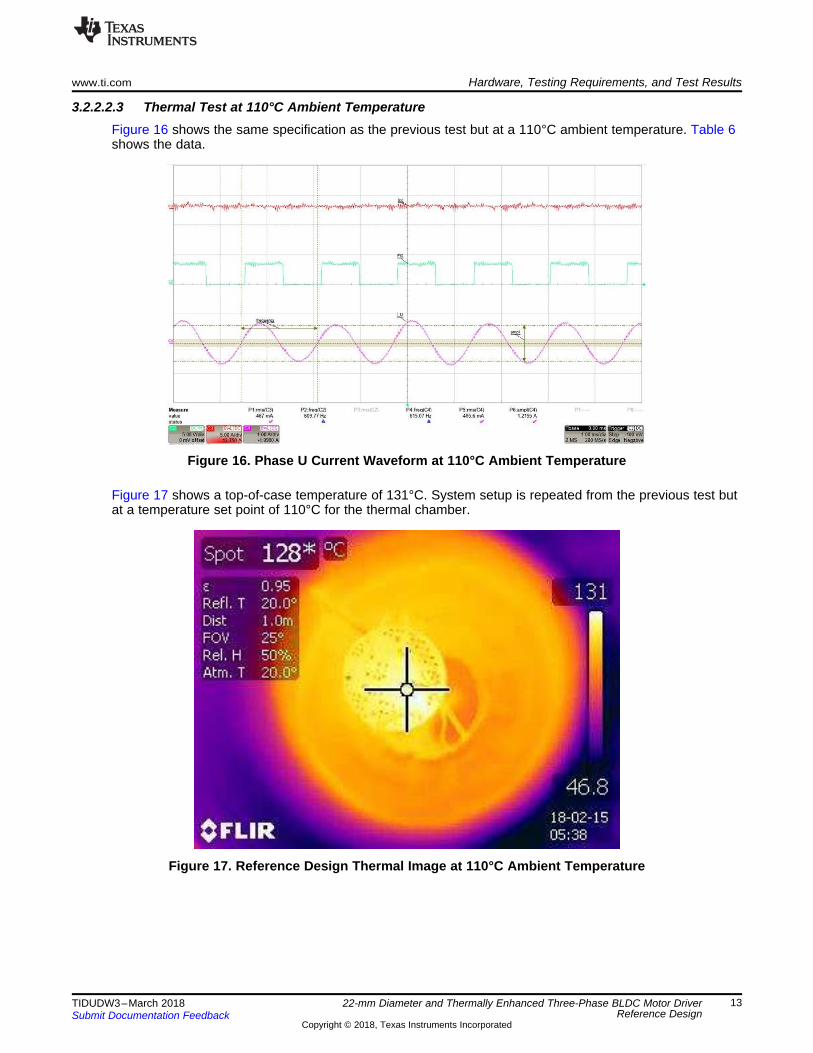
3.2.2.2.3 Thermal Test at 110°C Ambient TemperatureFigure 16 shows the same specification as the previous test but at a 110°C ambient temperature. Table 6shows the data.
Figure 16. Phase U Current Waveform at 110°C Ambient Temperature
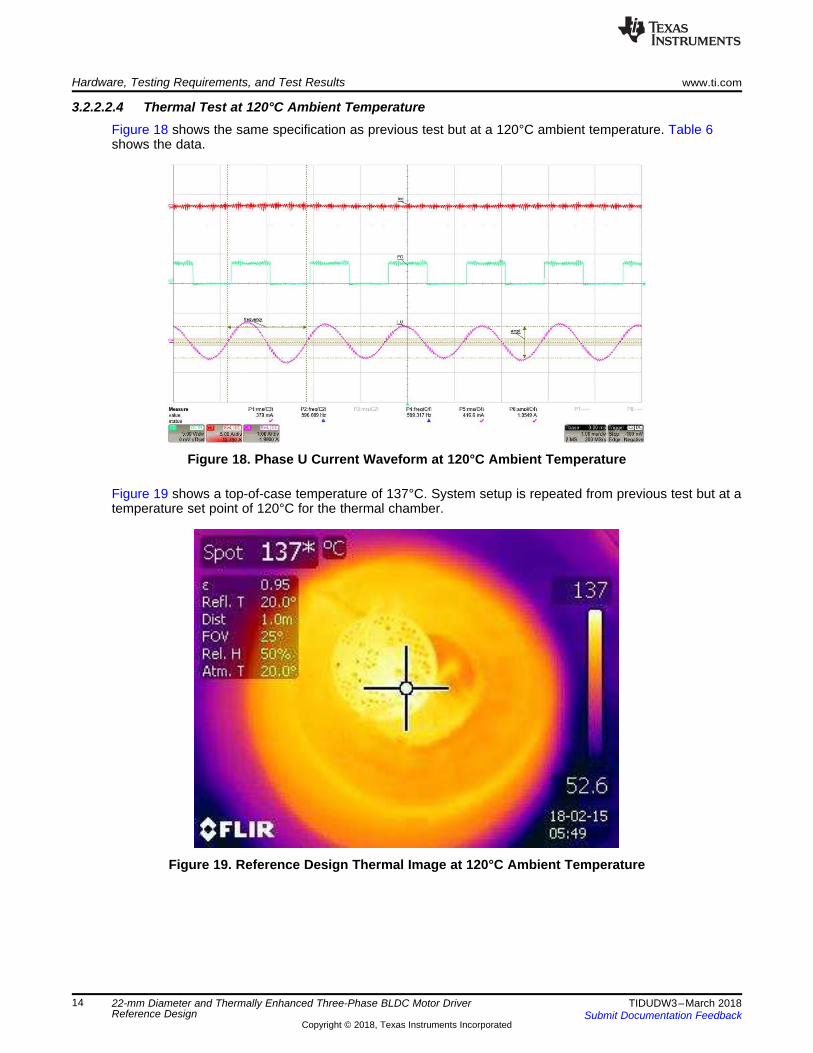
Figure 17 shows a top-of-case temperature of 131°C. System setup is repeated from the previous test butat a temperature set point of 110°C for the thermal chamber.
Figure 17. Reference Design Thermal Image at 110°C Ambient Temperature
Hardware, Testing Requirements, and Test Results www.ti.com
14 TIDUDW3–March 2018Submit Documentation Feedback
Copyright © 2018, Texas Instruments Incorporated
22-mm Diameter and Thermally Enhanced Three-Phase BLDC Motor DriverReference Design
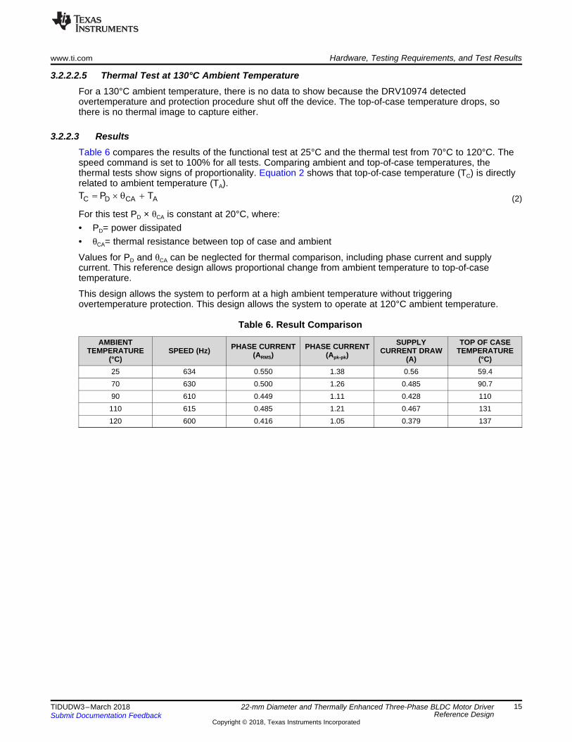
3.2.2.2.4 Thermal Test at 120°C Ambient TemperatureFigure 18 shows the same specification as previous test but at a 120°C ambient temperature. Table 6shows the data.
Figure 18. Phase U Current Waveform at 120°C Ambient Temperature
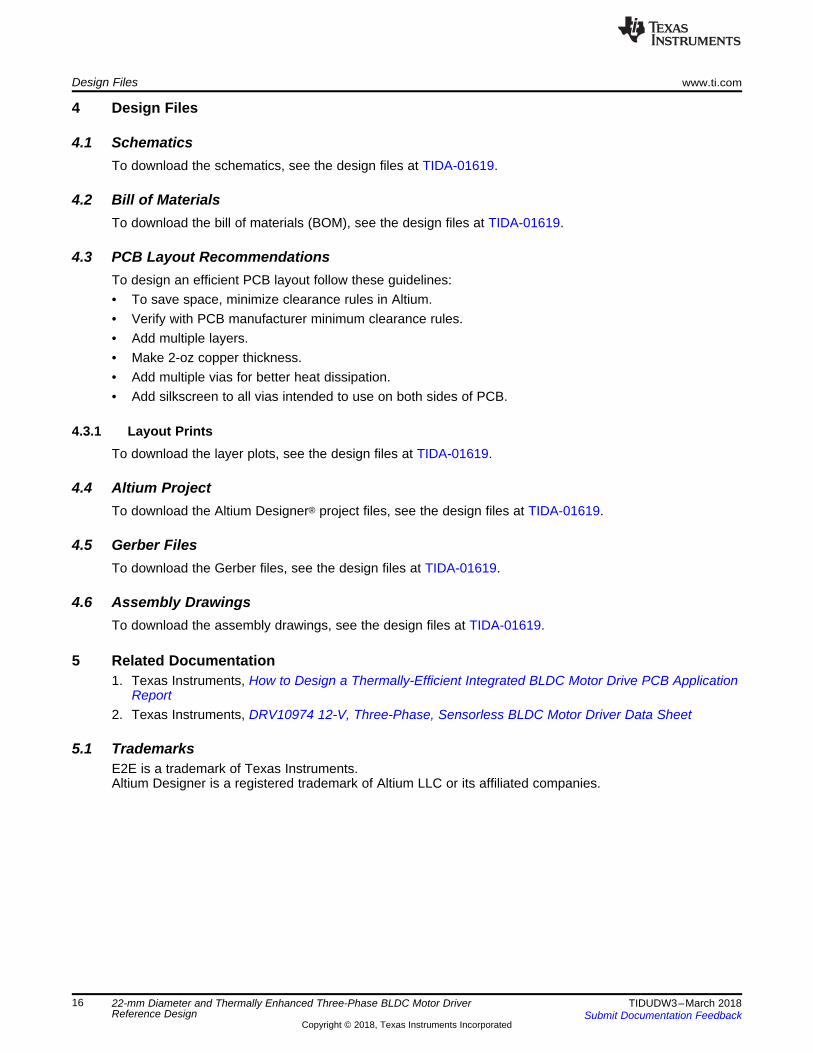
Figure 19 shows a top-of-case temperature of 137°C. System setup is repeated from previous test but at atemperature set point of 120°C for the thermal chamber.
Figure 19. Reference Design Thermal Image at 120°C Ambient Temperature
C D CA AT P T u T �
www.ti.com Hardware, Testing Requirements, and Test Results
15TIDUDW3–March 2018Submit Documentation Feedback
Copyright © 2018, Texas Instruments Incorporated
22-mm Diameter and Thermally Enhanced Three-Phase BLDC Motor DriverReference Design
3.2.2.2.5 Thermal Test at 130°C Ambient TemperatureFor a 130°C ambient temperature, there is no data to show because the DRV10974 detectedovertemperature and protection procedure shut off the device. The top-of-case temperature drops, sothere is no thermal image to capture either.
3.2.2.3 ResultsTable 6 compares the results of the functional test at 25°C and the thermal test from 70°C to 120°C. Thespeed command is set to 100% for all tests. Comparing ambient and top-of-case temperatures, thethermal tests show signs of proportionality. Equation 2 shows that top-of-case temperature (TC) is directlyrelated to ambient temperature (TA).
(2)
For this test PD × θCA is constant at 20°C, where:• PD= power dissipated• θCA= thermal resistance between top of case and ambient
Values for PD and θCA can be neglected for thermal comparison, including phase current and supplycurrent. This reference design allows proportional change from ambient temperature to top-of-casetemperature.
This design allows the system to perform at a high ambient temperature without triggeringovertemperature protection. This design allows the system to operate at 120°C ambient temperature.
Table 6. Result Comparison
AMBIENTTEMPERATURE
(°C)SPEED (Hz) PHASE CURRENT
(ARMS)PHASE CURRENT
(Apk-pk)SUPPLY
CURRENT DRAW(A)
TOP OF CASETEMPERATURE
(°C)25 634 0.550 1.38 0.56 59.470 630 0.500 1.26 0.485 90.790 610 0.449 1.11 0.428 110110 615 0.485 1.21 0.467 131120 600 0.416 1.05 0.379 137
Design Files www.ti.com
16 TIDUDW3–March 2018Submit Documentation Feedback
Copyright © 2018, Texas Instruments Incorporated
22-mm Diameter and Thermally Enhanced Three-Phase BLDC Motor DriverReference Design
4 Design Files
4.1 SchematicsTo download the schematics, see the design files at TIDA-01619.
4.2 Bill of MaterialsTo download the bill of materials (BOM), see the design files at TIDA-01619.
4.3 PCB Layout RecommendationsTo design an efficient PCB layout follow these guidelines:• To save space, minimize clearance rules in Altium.• Verify with PCB manufacturer minimum clearance rules.• Add multiple layers.• Make 2-oz copper thickness.• Add multiple vias for better heat dissipation.• Add silkscreen to all vias intended to use on both sides of PCB.
4.3.1 Layout PrintsTo download the layer plots, see the design files at TIDA-01619.
4.4 Altium ProjectTo download the Altium Designer® project files, see the design files at TIDA-01619.
4.5 Gerber FilesTo download the Gerber files, see the design files at TIDA-01619.
4.6 Assembly DrawingsTo download the assembly drawings, see the design files at TIDA-01619.
5 Related Documentation1. Texas Instruments, How to Design a Thermally-Efficient Integrated BLDC Motor Drive PCB Application
Report2. Texas Instruments, DRV10974 12-V, Three-Phase, Sensorless BLDC Motor Driver Data Sheet
5.1 TrademarksE2E is a trademark of Texas Instruments.Altium Designer is a registered trademark of Altium LLC or its affiliated companies.
www.ti.com Terminology
17TIDUDW3–March 2018Submit Documentation Feedback
Copyright © 2018, Texas Instruments Incorporated
22-mm Diameter and Thermally Enhanced Three-Phase BLDC Motor DriverReference Design
6 TerminologyBLDC— Brushless DC
OCP— Overcurrent protection
UVLO— Undervoltage lockout
OTP— Overtemperature protection
GND— Ground
FETs, MOSFETs—Metal-oxide-semiconductor field-effect transistor
PWM— Pulse width modulation
°C— Temperature in Celsius
oz— Ounce
MCU— Microcontroller
LDO— Low drop regulator
IMPORTANT NOTICE FOR TI DESIGN INFORMATION AND RESOURCES
Texas Instruments Incorporated (‘TI”) technical, application or other design advice, services or information, including, but not limited to,reference designs and materials relating to evaluation modules, (collectively, “TI Resources”) are intended to assist designers who aredeveloping applications that incorporate TI products; by downloading, accessing or using any particular TI Resource in any way, you(individually or, if you are acting on behalf of a company, your company) agree to use it solely for this purpose and subject to the terms ofthis Notice.TI’s provision of TI Resources does not expand or otherwise alter TI’s applicable published warranties or warranty disclaimers for TIproducts, and no additional obligations or liabilities arise from TI providing such TI Resources. TI reserves the right to make corrections,enhancements, improvements and other changes to its TI Resources.You understand and agree that you remain responsible for using your independent analysis, evaluation and judgment in designing yourapplications and that you have full and exclusive responsibility to assure the safety of your applications and compliance of your applications(and of all TI products used in or for your applications) with all applicable regulations, laws and other applicable requirements. Yourepresent that, with respect to your applications, you have all the necessary expertise to create and implement safeguards that (1)anticipate dangerous consequences of failures, (2) monitor failures and their consequences, and (3) lessen the likelihood of failures thatmight cause harm and take appropriate actions. You agree that prior to using or distributing any applications that include TI products, youwill thoroughly test such applications and the functionality of such TI products as used in such applications. TI has not conducted anytesting other than that specifically described in the published documentation for a particular TI Resource.You are authorized to use, copy and modify any individual TI Resource only in connection with the development of applications that includethe TI product(s) identified in such TI Resource. NO OTHER LICENSE, EXPRESS OR IMPLIED, BY ESTOPPEL OR OTHERWISE TOANY OTHER TI INTELLECTUAL PROPERTY RIGHT, AND NO LICENSE TO ANY TECHNOLOGY OR INTELLECTUAL PROPERTYRIGHT OF TI OR ANY THIRD PARTY IS GRANTED HEREIN, including but not limited to any patent right, copyright, mask work right, orother intellectual property right relating to any combination, machine, or process in which TI products or services are used. Informationregarding or referencing third-party products or services does not constitute a license to use such products or services, or a warranty orendorsement thereof. Use of TI Resources may require a license from a third party under the patents or other intellectual property of thethird party, or a license from TI under the patents or other intellectual property of TI.TI RESOURCES ARE PROVIDED “AS IS” AND WITH ALL FAULTS. TI DISCLAIMS ALL OTHER WARRANTIES ORREPRESENTATIONS, EXPRESS OR IMPLIED, REGARDING TI RESOURCES OR USE THEREOF, INCLUDING BUT NOT LIMITED TOACCURACY OR COMPLETENESS, TITLE, ANY EPIDEMIC FAILURE WARRANTY AND ANY IMPLIED WARRANTIES OFMERCHANTABILITY, FITNESS FOR A PARTICULAR PURPOSE, AND NON-INFRINGEMENT OF ANY THIRD PARTY INTELLECTUALPROPERTY RIGHTS.TI SHALL NOT BE LIABLE FOR AND SHALL NOT DEFEND OR INDEMNIFY YOU AGAINST ANY CLAIM, INCLUDING BUT NOTLIMITED TO ANY INFRINGEMENT CLAIM THAT RELATES TO OR IS BASED ON ANY COMBINATION OF PRODUCTS EVEN IFDESCRIBED IN TI RESOURCES OR OTHERWISE. IN NO EVENT SHALL TI BE LIABLE FOR ANY ACTUAL, DIRECT, SPECIAL,COLLATERAL, INDIRECT, PUNITIVE, INCIDENTAL, CONSEQUENTIAL OR EXEMPLARY DAMAGES IN CONNECTION WITH ORARISING OUT OF TI RESOURCES OR USE THEREOF, AND REGARDLESS OF WHETHER TI HAS BEEN ADVISED OF THEPOSSIBILITY OF SUCH DAMAGES.You agree to fully indemnify TI and its representatives against any damages, costs, losses, and/or liabilities arising out of your non-compliance with the terms and provisions of this Notice.This Notice applies to TI Resources. Additional terms apply to the use and purchase of certain types of materials, TI products and services.These include; without limitation, TI’s standard terms for semiconductor products http://www.ti.com/sc/docs/stdterms.htm), evaluationmodules, and samples (http://www.ti.com/sc/docs/sampterms.htm).
Mailing Address: Texas Instruments, Post Office Box 655303, Dallas, Texas 75265Copyright © 2018, Texas Instruments Incorporated