2/2-way and t valve bodies in stainless steel€¦ · b36.19m 10s code 63 ansi/ asme b36.19m 40s...
TRANSCRIPT

2/2-Way and T Valve Bodies in Stainless Steel

Leading the world in pharmaceutical and biotechnology industry sterilisation processes
GEMÜ is one of the leading manufacturers of valves, measurement and control systems and is the world market leader for sterile valve applications in the pharmaceutical and biotechnology industries. This position is based on GEMÜ's comprehensive investments in application-oriented research & development, amounting to more than 5% of the company's turnover.
Customized solutions for your project business
GEMÜ provides the optimal solution from a single source.
As a system supplier of isolation, actuator and control technology, we can respond very fl exibly to your individual project-specifi c needs.
Our worldwide sales network provides fast reaction times, customer oriented service and a committed project manage-ment team.

www.gemu-group.com 3
2/2-Way Valve BodiesDescription of use 4Material selection 5Grades of surface fi nish 6Butt weld connections 7Selection of operators 8 - 10Butt weld spigots for EN ISO 1127 pipes , code 60 11Butt weld spigots for DIN pipes, code 0 12Butt weld spigots for DIN 11850 pipes, series 1, code 16 13Butt weld spigots for DIN 11850 pipes, series 2, code 17; DIN 11866, series A, code 1A 14Butt weld spigots for DIN 11850 pipes, series 3, code 18 15Butt weld spigots for ASME BPE pipes, code 59 16Butt weld spigots for BS 4825 pipes, code 55 17Butt weld spigots for JIS-G 3447 pipes, code 35 18Butt weld spigots for JIS-G 3459 pipes, code 36 19Butt weld spigots for SMS 3008 pipes, code 37 20Clamp bodies 21Clamps ASME BPE for ASME BPE pipes, short design, code 80 22Clamps following ASME BPE for EN ISO 1127 pipes, code 82 23Clamps ASME BPE for ASME BPE pipes, code 88 24Clamps DIN 32676 for DIN 11850 pipes, code 8A 25Clamps SMS 3017 for SMS 3008 pipes, code 8E 26Clamps IDF/ISO for JIS-G 3447 pipes, code 8F 27Clamps IDF/ISO for JIS-G 3459 pipes, code 8H 28Clamp ASME BPE (short design), code 80 - butt weld spigot ASME BPE, code 59 29Clamp ASME BPE, length EN 558-1 series 7, code 82 - butt weld spigot EN ISO 1127, code 60 30Clamp ASME BPE, length EN 558-1 series 7, code 88 - butt weld spigot ASME BPE, code 59 31Clamp DIN 32676, code 8A - butt weld spigot DIN 11850 series 1, code 16 32
Clamp DIN 32676, code 8A - butt weld spigot DIN 11850 series 2, code 17 33Clamp DIN 32676, code 8A - butt weld spigot DIN 11850 series 3, code 18 34Clamp IDF/ISO for JIS-G 3447 pipes, code 8F - butt weld spigot JIS-G 3447, code 35 35Clamp IDF/ISO for JIS-G 34597 pipes, code 8H - butt weld spigot JIS-G 3459, code 36 36Clamp SMS 3017, length EN 558-1 series 7, code 8E - butt weld spigot SMS 3008, code 37 37Aseptic clamps 38Dairy pipe and aseptic unions 39Aseptic fl anges 40Kv value 41Order code 42Angle of rotation for optimum draining 43GEMÜ angle gauge 44
T valve bodiesDescription of use 45Material selection 46Grades of surface fi nish 47T valve bodies for sampling, body version "A" 48T valve bodies for EN ISO 1127 pipes, DN 6 - DN 150 49 - 51T valve bodies for DIN pipes, DN 6 - DN 150 52 - 55T valve bodies for ASME - BPE pipes, DN 8 - DN 150 56 - 57T valve bodies for JIS-G3447 pipes, DN 25 - DN 100 58T valve bodies for JIS-G3459 pipes, DN 6 - DN 100 59 - 61T valve bodies for SMS 3008 pipes, DN 25 - DN 100 62 - 63T valve bodies with clamp connections 64Order code 65Materials and certifi cates 66GEMÜ manufacturing sites and sales locations worldwide 67
Table of contents

4
Description of use2/2-way valve bodies
2/2-way straight through valve bodies are the body versions used most often in industrial applications. Butt weld spigots and clamp connections are the most common connections in sensitive sterile areas
whereas threaded connections, aseptic fl anges and threaded sockets only play a secondary role here.
Features• Standard valve body material 1.4435 in investment cast,
forged or block material design. 1.4539 and other materials on request
• Standard connections are butt weld spigots, clamps and sterile connections, other connections on request
• Internal surface contour mechanically polished and/orelectropolished down to Ra 0.25 μm
• Compact design, GMP-compliant design
• Available with manual, pneumatic or motorized operators (modular system)

www.gemu-group.com 5
Material selection2/2-way valve bodies
Other valve body materials Code
1.4539, block material 44
3.7035, titanium A1
2.4602, block material Hastelloy C 22 (NiCr21Mo14W) A3
Special materials on request
Forged body
Material code40 1.4435 (F316L)
42 1.4435 (BN2) Fe<0,5%
F4 1.4539 (F904L)
Block material
Material code41 1.4435 (316L/F316L)
43 1.4435 (BN2) Fe<0,5%
Investment casting
Material code32 1.4435 (BN2) Fe < 0.5%
34 1.4435 (ASTM A 351 CF3M)*
* Material equivalency 316 L

6
Grades of surface fi nish2/2-way valve bodies
Modern, ergonomically shaped workstations and trained polishing staff give us the ability to provide high quality surface fi nishes. Depending on the required application, surface fi nishes from Ra 0.8 μm down to 0.25 μm can be achieved by polishing, electro polishing or a special process, we call “elysieren“.
Mechanical hand polishing is carried out at our works to ensure our high quality standard.
GEMÜ DE GEMÜ US DIN 11866 ASME BPE (2014)Code Ra μm Ramax μinch Hygiene class Ra μm Designation Ramax μinch Ra μm -
converted1502 ≤ 0.8 30 H3 ≤ 0.8 SF3 30 0.76
1503 ≤ 0.8 30 HE3c ≤ 0.8 - - -
1508 ≤ 0.6 25 - - SF6 25 0.64
1507 ≤ 0.6 25 - - SF2 25 0.64
1537 ≤ 0.4 20 HE4c ≤ 0.4 SF5 20 0.51
1536 ≤ 0.4 20 H4 ≤ 0.4 SF1 20 0.51
1527 ≤ 0.25 15 H5 ≤ 0.25 - - -
1516 ≤ 0.25 15 HE5c ≤ 0.25 SF4 15 0.38
Valve body surface fi nish, internal contourForged body - Codes 40, 42, F4 Block material - Codes 41, 43
Investment castingCodes 32, 34 Code
Ra ≤ 0,8 μm (30 μinch) for media wetted surfaces, mechanically polished internal X X 1502
Ra ≤ 0,8 μm (30 μinch) for media wetted surfaces, electropolished internal/external X - 1503
Ra ≤ 0,6 μm (25 μinch) for media wetted surfaces, mechanically polished internal X 1 X 1 1507
Ra ≤ 0,6 μm (25 μinch) for media wetted surfaces, electropolished internal/external X 1 - 1508
Ra ≤ 0,25 μm (10 μinch) for media wetted surfaces, electropolished internal/external X 1 - 1516
Ra ≤ 0,25 μm (10 μinch) for media wetted surfaces, mechanically polished internal X 1 - 1527
Ra ≤ 0,4 μm (15 μinch) for media wetted surfaces, mechanically polished internal X 1 - 1536
Ra ≤ 0,4 μm (15 μinch) for media wetted surfaces, electropolished internal/external X 1 - 1537
Ra ≤ 0,5 μm (20 μinch) for media wetted surfaces, mechanically polished internal X 1 - 1927
Ra ≤ 0,5 μm (20 μinch) for media wetted surfaces, electropolished internal/external X 1 - 1928
Ra ≤ 0,4 μm (15 μinch) for media wetted surfaces, electropolished internal/external X 1 - 1929
Ra acc. to DIN 4768; at defi ned reference points. 1 For pipe inside diameter< 6 mm, the surface inside the spigot is Ra ≤ 0.8 μm.
www.gemu-group.com 7
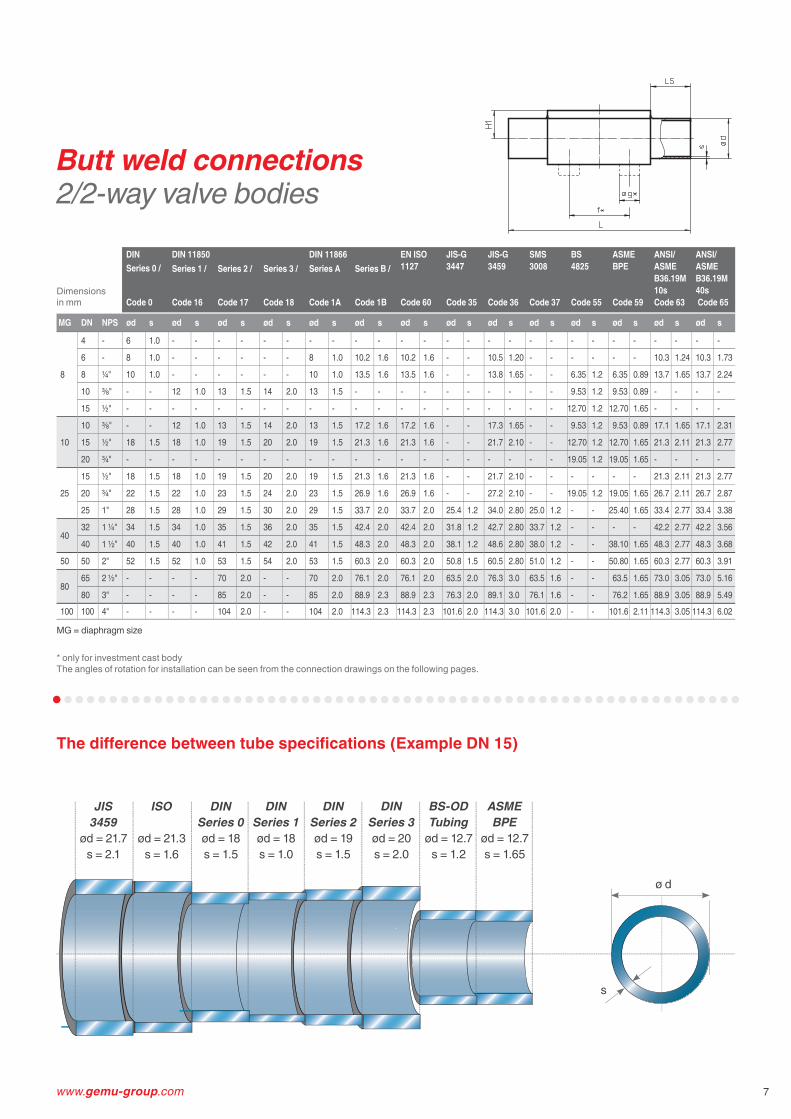
* only for investment cast bodyThe angles of rotation for installation can be seen from the connection drawings on the following pages.
Butt weld connections2/2-way valve bodies
The diff erence between tube specifi cations (Example DN 15)
ISO
ød = 21.3s = 1.6
JIS3459
ød = 21.7s = 2.1
DINSeries 0ød = 18s = 1.5
DINSeries 1ød = 18s = 1.0
DINSeries 2ød = 19s = 1.5
DINSeries 3ød = 20s = 2.0
BS-ODTubing
ød = 12.7s = 1.2
ASMEBPE
ød = 12.7s = 1.65
ø d
s
Dimensions in mm
DINSeries 0 /
DIN 11850 DIN 11866 EN ISO1127
Code 60
JIS-G3447
Code 35
JIS-G3459
Code 36
SMS3008
Code 37
BS 4825
Code 55
ASME BPE
Code 59
ANSI/ASME B36.19M 10s Code 63
ANSI/ASME B36.19M 40s Code 65
Series 1 / Series 2 / Series 3 / Series A Series B /
Code 0 Code 16 Code 17 Code 18 Code 1A Code 1B
MG DN NPS ød s ød s ød s ød s ød s ød s ød s ød s ød s ød s ød s ød s ød s ød s
8
4 - 6 1.0 - - - - - - - - - - - - - - - - - - - - - - - - - -
6 - 8 1.0 - - - - - - 8 1.0 10.2 1.6 10.2 1.6 - - 10.5 1.20 - - - - - - 10.3 1.24 10.3 1.73
8 ¼" 10 1.0 - - - - - - 10 1.0 13.5 1.6 13.5 1.6 - - 13.8 1.65 - - 6.35 1.2 6.35 0.89 13.7 1.65 13.7 2.24
10 ⅜" - - 12 1.0 13 1.5 14 2.0 13 1.5 - - - - - - - - - - 9.53 1.2 9.53 0.89 - - - -
15 ½" - - - - - - - - - - - - - - - - - - - - 12.70 1.2 12.70 1.65 - - - -
10
10 ⅜" - - 12 1.0 13 1.5 14 2.0 13 1.5 17.2 1.6 17.2 1.6 - - 17.3 1.65 - - 9.53 1.2 9.53 0.89 17.1 1.65 17.1 2.31
15 ½" 18 1.5 18 1.0 19 1.5 20 2.0 19 1.5 21.3 1.6 21.3 1.6 - - 21.7 2.10 - - 12.70 1.2 12.70 1.65 21.3 2.11 21.3 2.77
20 ¾" - - - - - - - - - - - - - - - - - - - - 19.05 1.2 19.05 1.65 - - - -
25
15 ½" 18 1.5 18 1.0 19 1.5 20 2.0 19 1.5 21.3 1.6 21.3 1.6 - - 21.7 2.10 - - - - - - 21.3 2.11 21.3 2.77
20 ¾" 22 1.5 22 1.0 23 1.5 24 2.0 23 1.5 26.9 1.6 26.9 1.6 - - 27.2 2.10 - - 19.05 1.2 19.05 1.65 26.7 2.11 26.7 2.87
25 1" 28 1.5 28 1.0 29 1.5 30 2.0 29 1.5 33.7 2.0 33.7 2.0 25.4 1.2 34.0 2.80 25.0 1.2 - - 25.40 1.65 33.4 2.77 33.4 3.38
4032 1 ¼" 34 1.5 34 1.0 35 1.5 36 2.0 35 1.5 42.4 2.0 42.4 2.0 31.8 1.2 42.7 2.80 33.7 1.2 - - - - 42.2 2.77 42.2 3.56
40 1 ½" 40 1.5 40 1.0 41 1.5 42 2.0 41 1.5 48.3 2.0 48.3 2.0 38.1 1.2 48.6 2.80 38.0 1.2 - - 38.10 1.65 48.3 2.77 48.3 3.68
50 50 2" 52 1.5 52 1.0 53 1.5 54 2.0 53 1.5 60.3 2.0 60.3 2.0 50.8 1.5 60.5 2.80 51.0 1.2 - - 50.80 1.65 60.3 2.77 60.3 3.91
8065 2 ½" - - - - 70 2.0 - - 70 2.0 76.1 2.0 76.1 2.0 63.5 2.0 76.3 3.0 63.5 1.6 - - 63.5 1.65 73.0 3.05 73.0 5.16
80 3" - - - - 85 2.0 - - 85 2.0 88.9 2.3 88.9 2.3 76.3 2.0 89.1 3.0 76.1 1.6 - - 76.2 1.65 88.9 3.05 88.9 5.49100 100 4" - - - - 104 2.0 - - 104 2.0 114.3 2.3 114.3 2.3 101.6 2.0 114.3 3.0 101.6 2.0 - - 101.6 2.11 114.3 3.05 114.3 6.02
MG = diaphragm size

8
Manually operated
Type GEMÜ 9601 GEMÜ 9602 GEMÜ 9612 GEMÜ 9673 GEMÜ 9653 GEMÜ 9654
Material
Stainless steel, plastic handwheel, with optical position indicator and seal adjuster
Stainless steel, with optical position indicator and seal adjuster
Stainless steel, plastic handwheel, with optical position indicator and seal adjuster
Stainless steel, plastic handwheel, with optical position indicator and seal adjuster
Stainless steel, plastic handwheel, with optical position indicator, stroke lim-iter and seal adjuster, lockable, optional: electrical position indicator
Stainless steel, with optical position indi-cator, stroke limiter and seal adjuster, lockable, optional: electrical position indicator
Autoclavable ● ● ● ● ● ●Operating temperature* -10 to 150 °C -10 to 150 °C -10 to 150 °C -10 to 150 °C -10 to 150 °C -10 to 150 °C
Operating pressure* 0 to 10 bar 0 to 10 bar 0 to 10 bar 0 to 10 bar 0 to 10 bar 0 to 10 bar
DN 4 - 15 4 - 15 10 - 20 15 - 50 10 - 100 4 - 100
Diaphragm size 8 ● ● - - - ●Diaphragm size 10 - - ● - ● ●Diaphragm size 25 - - - ● ● ●Diaphragm size 40 - - - ● ● ●Diaphragm size 50 - - - ● ● ●Diaphragm size 80 - - - - ● ●Diaphragm size 100 - - - - ● ●
* dependent on diaphragm material, see technical datasheet
Elastomer diaphragmsEPDM
PTFE diaphragmsPTFE/EPDM, PTFE/FPM
Selection of operators2/2-way valve bodies

www.gemu-group.com 9
Pneumatically operated
GEMÜ 9605 GEMÜ 9625 GEMÜ 9687 GEMÜ 9650 GEMÜ 9650TL GEMÜ 9651 GEMÜ 9658/9688 GEMÜ 9660Plastic, with stain-less steel distance piece, optical position indicator
Plastic, with stain-less steel distance piece, optical position indicator
Plastic, with stain-less steel distance piece, optical position indicator
Stainless steel, with optical position indicator, optionally autoclavable
Safety valve, stainless steel, mounting facility for proximity switches
Stainless steel, with integrated automation module
Two stage actuator, stainless steel
Filling valve, stainless steel with optical position indicator, stroke limiter and seal adjuster
- - - ● (DN 4-25) - - - -
-10 to 150 °C -10 to 150 °C -10 to 150 °C -10 to 150 °C -10 to 150 °C -10 to 150 °C -10 to 150 °C -10 to 150 °C
0 to 8 bar 0 to 6 bar 0 to 10 bar 0 to 10 bar 0 to 8 bar 0 to 10 bar 0 to 10 bar 0 to 5 bar
4 - 15 10 - 20 10 - 100 4 - 100 4 - 25 4 - 25 10 - 50 4 - 25
● - - ● ● ● ● ●- ● ● ● ● ● ● ●- - ● ● ● ● ● ●- - ● ● - - ● -
- - ● ● - - ● -
- - ● ● - - - -
- - ● ● - - - -
Valve body versions
Connections
2/2-way bodyinvestment casting2/2-way version to all international standard butt weld connections
2/2-way bodyforged version2/2-way version to all international standard butt weld connections
Other versions and accessories available. See "Stainless Steel Diaphragm Valves" brochure.
Aseptic unionsto all common standards
Aseptic clampsto all common standards
Aseptic fl angesto all common standards
Clampsto all common standards
tic clamps

10
Pneumatically operated Motorized
Type GEMÜ 9615 GEMÜ 9695 GEMÜ 9618 GEMÜ 9698
Material
Plastic, with optical position indicator,only for 2/2-way valve bodies
Plastic, with optical position indicator,only for 2/2-way valve bodies
Plastic, with/without stainless steel distance piece, with optical position indicator
Plastic, with stainless steel distance piece, with optical position indicator and manual override
Autoclavable - - - -
Operating temperature* -10 to 80 °C -10 to 80 °C0 to 130 °C(without distance piece 15 to 50 °C)
-10 to 150 °C
Operating pressure* 0 to 6 bar 0 to 10 bar 0 to 6 bar 0 to 6 bar
DN 10 to 20 15 to 50 4 - 15 15 - 50
Supply voltage - - 24 VAC, 120 VAC, 230 VAC, 50/60Hz
24 VAC, 120 VAC, 230 VAC, 50/60Hz
Diaphragm size 8 - . ● -
Diaphragm size 10 ● . ● -
Diaphragm size 25 - ● - ●Diaphragm size 40 - ● - ●Diaphragm size 50 - ● - ●Diaphragm size 80 - - - -
Diaphragm size 100 - - - -
* dependent on diaphragm material
Selection of operators2/2-way valve bodies

www.gemu-group.com 43
In the pharmaceutical and biotechnological industries and other sensitive industrial sectors the drainability and cleanability of plant plays an important role. Very often plants are cleaned and sterilised after every production process. The objective is to keepthe residue as low as possible in order to optimise the sterilisation and cleaning processes of plant and piping systems.In specialist literature and documents from plant constructors and valve manufacturers the term “self-draining“ is oftenused in this context. It is a fi cticious term for the independent emptying of a vessel and/or a pipe section through an opened valve. Depending on a variety of factors it is how-ever not normally possible to expect full drainage without leaving residue even with vertical piping. Therefore the term “self-draining“ is often used incorrectly. The term “free outlet“, “unhindered outlet“ or “optimum draining“ is more realistic. At GEMÜ we use the term optimum draining.
Optimum drainability of a valve depends on several factors:
• Design of the internal geometry of the valve body
• Diff erent pipe standards (ISO, DIN, SMS, ASME BPE, JIS etc.), as they have diff erent inside diameters at the same nominal size
• Installation position in the pipeline with regard to horizontal rotation and vertical inclination
• Viscosity and adhesive qualities of the medium/media
Diaphragm valves off er the best structural conditions for an unhindered outlet of the working medium when the valve is open. In an ideal case, the pipe and the valve are vertical. However, if the pipe is horizontal, the valve must be turned axially in the pipe until the outermost point of the sealing weir corresponds to the lowest point of the connecting pipe. Thus the working mediumcan optimally fl ow around the weir. The only way to gain the necessary viewing point to set the rotation angle is to remove the operator (manual bonnet or actuator) prior to installing the valve. Optical alignment is often suffi cient – it must be noted, however, that the eyes of the viewer must be in line with the transition of the weir and the lowest point of the pipe. Dependent on the viscosity of the working medium or the required outlet velocity, the pipe runs should have a corresponding gradient (pipe inclination).
GEMÜ has calculated draining angles for the various nominal sizes and pipe standards in order to facilitate installation of valves for optimised draining. The draining angles mentioned are valid for installation in horizontal pipe systems. The GEMÜ angle α is quoted from when the valve is lying on its side with a vertical weirplate and the rotation angle is UPWARDS. Please note the drawing. (Attention: Other manufacturers quote the angle using a horizontal weirplate from the vertical centreline downwards).The draining angles mentioned in this brochure are valid for valve bodies produced in the EU. Please contact your local supplier for further information. The values of the draining angles are only provided as a guide without tolerances. Drainability in a plant is the responsibility of the plant designer, plant constructor and end user due to factors described previously.
Angle of rotation for optimum draining

44
GEMÜ angle gauge
2 rigid location spigots
Base plate
Angle scalesetting range ± 65°
Angle indicatorlocking screw
Angle indicatorwith spirit level
Location spigot with eccentric cam
Indication of valve body fl ow directionDiaphragm size identifi cation
GEMÜ has developed a patented angle gauge to simplify mounting 2/2-way stainless steel diaphragm valve bodies. The angle gauge enables quick and simple determination of the correct mounting position of a diaphragm valve body. The angle gauge is placed on the valve body so that its location spigots engage in the holes intended for actuator fi xing. It is then locked by an eccentric cam at one of the location spigots. The fl ow direction is clearly identifi ed to prevent incorrect positioning. The correct installation angle, dependent on the valve body type, is indicated in this brochure. The given angle is set on the angle gauge. The valve body is rotated until the spirit is level. Then the body can be installed in the piping. The angle gauge is available for diaphragm sizes MG 8 - 100.
Please use the article numbers listed below when ordering:
Angle gauge for diaphragm size 8: 88278996
Angle gauge for diaphragm size 10: 88277372
Angle gauge for diaphragm size 25: 88277373
Angle gauge for diaphragm size 40: 88277374
Angle gauge for diaphragm size 50: 88277375
Angle gauge for diaphragm size 80: 88277376
Angle gauge for diaphragm size 100: 88379424

www.gemu-group.com
GEMÜ Gebr. Müller Apparatebau GmbH & Co. KGFritz-Müller-Straße 6-8 · D-74653 Ingelfi ngen-CriesbachPhone +49 (0)7940 123-0 · [email protected]
Subj
ect t
o al
tera
tion
· 04/
2016
· 88
4714
95