2/2-way angle seat control valve, threaded and weld end connections… · 2011-10-19 · 2/2-way...
TRANSCRIPT

2702
p. �/8
Type 1067
Positioner SideControl
Type 8635
Positioner SideControl
2/2-way Angle Seat Control Valve, threaded and weld end connections, 1/2” – 2”
The 2702 Control Valve consists of an 316L angle seat body with a rugged pneumatic piston actuator.
The parabolic trim results in a flow characteristic approximately 35% larger than conventional control valves. It is available in either stainless steel on stainless steel or with a durable PTFE seal for tight shut-off.
Type 2702 can be actuated by the Continuous TopControl Type 8630 or SideControl Type 1067 and 8635. TopControl/SideControl thus forms a mechanical and functional unit with the pneumatic actuator as a complete control valve system.
This system has been engineered for reliable accurate control in applications where high flow rate is an advantage.
Type 8630
Positioner TopControl continuous
Type 2702 can be combined with...
Type 8323
Pressure transmitter
Type 8030
Flow sensor
•Excellentcontrolcharacteristicandhighflowrates
•Durable,robustandcosteffective
•Compactdesign,lowweight
Technical dataMaterialsBodyActuator
Caststainlesssteel316L(conformto1.4409)PA(polyamide)(PPSonrequest)
Sealing SS/SS(stainlesssteel/stainlesssteel)PTFE/SS(PTFE/stainlesssteel)
Seat leakage IEC 534-4/EN 1349
Shut-offclassIVforSt.st./St.st.Shut-offclassVIforPTFE/St.st.
Process media gases and liquids (vacuum version on request)
Forneutralgases,water,alcohols,oils,fuels,hydraulicliquids,saltsolutions,lyes,organicsolvents,steam(150PSI/366°F)
Viscosity Max..94in2/s(600mm2/s)
Packing gland PTFEV-rings(siliconegrease)withspringloadingNominal pressure 362PSI(bodyrating);232PSI(actuatorshutoff)Temperatures Fluid
Ambient
14°Fto366°F(-10°Cto+185°C)1)(max.266°F(+130°C)forPTFE/St.st.sealingrecommended)14°Fto140°F(-10°Cto+60°C)1)
Control media CompressedairPilot pressure 80to100PSI(5.5to7bar)Pilot air ports G1/4stainlesssteel(SS)Flow direction BelowseatMounting position Any,preferablyuprightFlow characteristic ModifiedequalpercentageControl ratio (CVS/CVO) Morethan50:1Port connections Threaded NPT G
Rc
Weldend OD-Tube ISO DIN SMS
ANSI/ASMEB1.20.1 face-to-faceDIN3202-4M4DINISO228 face-to-faceDIN3202-4M4(onrequest) face-to-faceDIN3202-4M8ISO7 face-to-faceDIN3202-4M4ASMEBPEISO4200(onrequest)DIN11850series2(onrequest)SMS3008(onrequest)BS4821part1(onrequest)
1)hightemperatureversiononrequest
Proven Applications
• FoodandbeverageCIP/SIPandauxiliaryprocesseswithsteam,chilledwaterandglycol
• Textilemachinery(steam,water,air)anddyeing
• Heatexchangersandautoclaves• Sterilizersandwashers• Distillationapparatus• Packagingandfillingmachinery
Type 8400
Temperature transmitter
CompleteBurkertsystemusingType2702withSideControl1067
CompleteBurkertsystemusingType2702withTopControl8630

p. �/8
2702
A complete continuous angle seat valve system consists of an angle seat control valve Type 2702 and a valve actuation system SideControl Type 1067 or Type 8635 or TopControl Type 8630. The positioners are only delivered in combination with an actuator as a part of a complete control valve. The following information is necessary for the selection of a complete control valve:• Item no. of the seat control valve Type 2702 (see Ordering chart) • Item no. of the desired positioner Type 8630, 1067 or 8635 (see separate datasheets)
0/4-20mA0-5/10V
Valve actuation system:TopControl Type 8630, 3-wire
TheType8630isadigitalelectropneumaticpositionertobecombinedwithpneumaticallyactuatedprocessvalves.Itscompactdesignwithanintegratedpositionencoderanddigitaltextdisplaywasdesignedforthegrowingrequirementsofindustrialapplications.Signalprocessing,regulation,andcontroloftheinternalpositioningsystemaredoneusingmicroprocessor-controlledelectronics.Thankstoitseasy-to-useoperatingstructure,thepositionerissimpleandeasytooperatedespiteitswiderangeoffunctionality.
Importantfeatures:•Automaticcommissioningofthecontrolvalve systemandtheoptionalprocesscontroller usingthefunctionsX-TuneorP.Co-Tune•Automaticormanualdefinitionofcorrection characteristiccurves•Binaryinputsandoutputs•Analogoutput•FitseamlesslytoBükertprocessvalve systems•24VDC
Valve actuation system:SideControl Type 8635, 2-wire, intrinsically safe
4-20mA
TheType8635isadigitalelectropneumaticpositionertobecombinedwithpneumaticallyactuatedprocessvalves.Itsrobust,compactdesignwasdesignedforthegrowingrequirementsoftheprocesstechnologyindustry.Signalprocessing,regulation,andcontroloftheinternalpositioningsystemaredoneusingmicroprocessor-controlledelectronics.Thankstoitseasy-to-useoperatingstructure,thepositionerissimpleandeasytooperatedespiteitswiderangeoffunctionality.
Importantfeatures:•Automaticcommissioningofthecontrolvalve systemandtheoptionalprocesscontroller usingthefunctionsX-TuneorP.Co-Tune•Automaticormanualdefinitionofcorrection characteristiccurves•Binaryinputsandoutputs•Analogoutput•Mountingonvariableactingvalvesaccording toDINIEC534-6(NAMUR)andBürkert processcontrolvalves•2-wire,powersupplythroughsetpointor PROFIBUSPA•ATEXcertification II2GEExiaIICT6Zone1 II3G/DEExiaIICT6Zone2/22•Robusthousingofhardcoatedandplastic platedaluminum
TheType1067isadigitalelectropneumaticpositionertobecombinedwithpneumaticallyactuatedprocessvalves.Itsrobust,verycompactdesignwasdesignedforthegrowingrequirementsoftheprocesstechnologyindustry.Signalprocessing,regulation,andcontroloftheinternalorexternalpositioningsystemaredoneusingmicroprocessor-controlledelectronics.Thankstoitseasy-to-useoperatingstructure,thepositionissimpleandeasytooperatedespiteitswiderangeoffunctionality.
Importantfeatures:•Automaticcommissioningofthecontrol valvesystemusingtheX-Tunefunctions•Automaticormanualdefinitionofcorrection characteristiccurves.•Binaryinputsandoutputs•Analogoutput•Mountingonvariableactingvalvesaccording toDINIEC534-6(NAMUR)andBürkert processcontrolvalves•3-wire,24VDC•Keypad/displayunit•Remoteversionwithpositionerseparate fromcontrolvalve
Valve actuation system:SideControl Type 1067, 3-wire
0/4-20mA0-10V
Angle seat valve Type 2702 with required process connection
2702+8630 Angle seat valve TopControl system
2702+1067Angle seat valveSideControl system
Control valve with required body and port connectionPositioner
2702+8635Angle seat valveSideControl system
Examplesforvariationsofcontinuousangleseatvalvesystems
Angleseatvalvesystem

p. �/8
2702
A 2702 control valve with a 1067 local PID controller. The valve is controlling the exit temperature of a media flowing-through a heat ex-changer. The process input is a simple temperature transmitter.
CVvalues[gpm]*
Remarks on the flow characteristicModified equi-percentile flow characteristic, engineered for a quick response during peak flow demand (an advantage for many processes like heating/cooling with heat exchangers) and fine control at lower flow.
B¸rkertFluid Control Systems
D-74653 Ingelfingen
Ausg./Vers. Antrag ƒnderung Datum Gez. Gepr. Norm QS
Datum Name
Bearbeiter
Gepr¸ft
Norm
QS
Mafle ohne Toleranzangabe
L‰ngenmafle
Rundungshalbmesser
Winkelmafle
Klass-Nr.
Maflstab
Typ
Variantenst¸ckliste
Werkstoff
Benennung
Zeichnungs-Nr.
Ers.f.
SW
Blatt
2702 2702 BG01
Regelventil ANTG F; G
- / -
Antrieb ¯ 80, 100
11
x
27.05.2004 ma
von
Adapter: Stainlesssteel1.4305
Actuator: PApolyamide(PPSonrequest)
Pilotairports: Stainlesssteel1.4305
Spring: Stainlesssteel1.4568
V-seals: PTFE
Nipple: Stainlesssteel1.4401
Spindle: Stainlesssteel1.4401
Pin: Stainlesssteel1.4310
Valvebody: Caststainlesssteel316L
Plug: Stainlesssteel1.4571(+PTFEdiscforsoftseatsealing)
Wiper: PTFE
Applicationexample
Flowcharacteristic
Port size and Actuator Stroke [%]
orifice [mm] size [mm] 5 10 20 30 40 50 60 70 80 90 100
13/15 F-80 0.26 0.28 0.30 0.40 0.81 2.1 3.3 4.0 4.6 5.0 5.2
20 F-80 0.35 0.38 0.49 0.81 3.3 6.2 7.7 8.7 9.5 10.0 10.5
25 F-80 0.45 0.47 0.70 1.46 5.2 9.9 12.2 14.2 15.7 16.6 17.5
32 F-80 0.64 0.76 1.11 1.75 4.6 10.8 16.1 19.3 21.9 24.5 26.9
40 G-100 0.76 0.99 1.75 5.8 16.3 23.4 29.2 31.5 35.1 38.6 40.9
50 G-100 1.17 1.52 2.3 5.8 18.7 31.5 39.7 47.9 52.6 57.3 62.0
Materials*Basedonwaterat68°F,1PSIdifferential
CV/CVS [%]100
9080
6050403020100
0 10 20 30 40 50 60 70 80 90 100Stroke [%]
70

p. �/8
2702
Co
ntr
ol
fun
ctio
n
Port size and orifice
Act
uato
r si
ze Ø
[m
m]
CVs
valu
e
[g
pm
]1)
Op
. p
ress
ure
≤
366
°F
[PS
I]
Item
no
. se
al
sy
stem
2)
SS
/SS
Item
no
. se
al
sy
stem
2)
PTF
E/S
S
[mm
]
[in
ch]
Threaded ports acc. NPT, ANSI/ASME B1.20.1, face-to-face acc. DIN 3202-4 M4, flow below seat
A 13 1/2” F-80 5.2 232 462101 462095
20 3/4” F-80 10.5 232 462102 462096
25 1” F-80 17.5 232 462103 462097
32 11/4” F-80 26.9 217.5 462104 462098
40 11/2” G-100 40.9 181.25 462105 462099
50 2” G-100 62.0 104.4 462106 462100
B 13 1/2” F-80 5.2 232 462115 462107
20 3/4” F-80 10.5 232 462116 462108
25 1” F-80 17.5 232 462110 462111
32 11/4” F-80 26.9 217.5 462121 462112
40 11/2” G-100 40.9 181.25 462122 462113
50 2” G-100 62.0 104.4 462123 462114
Threadedport
2/2-way,NCbyspringreturn
A
P
B
P
2/2-way,NObyspringreturn
1)Basedonwaterat68°F,1PSIdifferential2)sealsystem:•St.st./St.st.:plugstainlesssteel/seatstainlesssteel•PTFE/St.st.:plugssw/PTFEinseat/seatstainlesssteel
Orderingchart:Angleseatvalve(withoutpositioner)
Co
ntr
ol
fun
ctio
n
Port size and orifice
Co
nn
ect
ion
D
S x
WS
[i
nch
]
Act
uato
r si
ze Ø
[m
m]
CVs
valu
e
[g
pm
]1)
Op
. p
ress
ure
≤
366
°F
[PS
I]
Item
no
. se
al
sy
stem
2)
SS
/SS
Item
no
. se
al
sy
stem
2)
PTF
E/S
S
[mm
]
[in
ch]
Weld end acc., U.S. tube ends
A 15 1/2” .50x.065 F-80 5.2 232 170392 170382
20 3/4” .75x.065 F-80 10.5 232 170440 170384
25 1” 1.00x.065 F-80 17.5 232 170441 170386
40 11/2” 1.50x.065 G-100 40.9 181 170442 170388
50 2” 2.00x.065 G-100 62.0 104 170443 170390
B 15 1/2” .50x.065 F-80 5.2 232 170464 170444
20 3/4” .75x.065 F-80 10.5 232 170465 170447
25 1” 1.00x.065 F-80 17.5 232 170466 170461
40 11/2” 1.50x.065 G-100 40.9 181 170467 170462
50 2” 2.00x.065 G-100 62.0 104 170468 170463
Weldend
2/2-way,NCbyspringreturn
A
P
B
P
2/2-way,NObyspringreturn
1)Basedonwaterat68°F,1PSIdifferential2)sealsystem:•St.st./St.st.:plugstainlesssteel/seatstainlesssteel•PTFE/St.st.:plugssw/PTFEinseat/seatstainlesssteel

p. �/8
2702
SparepartsforType2702-1/2”–2”(DN13-50)
Port size and orifice
Desc
rip
tio
n
Item
no
. [N
PT]
Item
no
. [T
ub
e]
[mm
]
[in
ch]
Type 8630 position only controller13 1/2” SYST–2702–462101–8630–459321 US11142 –20 3/4” SYST–2702–462102–8630–459321 US11143 –25 1” SYST–2702–462103–8630–459321 US11144 –32 11/4” SYST–2702–462104–8630–459321 US11145 –40 11/2” SYST–2702–462105–8630–459321 US11146 –50 2” SYST–2702–462106–8630–459321 US11147 –15 1/2” SYST–2702–170392–8630–459321 – US1113720 3/4” SYST–2702–170440–8630–459321 – US1113825 1” SYST–2702–170441–8630–459321 – US1113940 11/2” SYST–2702–170442–8630–459321 – US1114050 2” SYST–2702–170443–8630–459321 – US11141
Type 8630 PID controller13 1/2” SYST–2702–462101–8630–459290 US11153 –20 3/4” SYST–2702–462102–8630–459290 US11154 –25 1” SYST–2702–462103–8630–459290 US11155 –32 11/4” SYST–2702–462104–8630–459290 US11156 –40 11/2” SYST–2702–462105–8630–459290 US11157 –50 2” SYST–2702–462106–8630–459290 US11158 –15 1/2” SYST–2702–170392–8630–459290 – US1114820 3/4” SYST–2702–170440–8630–459290 – US1114925 1” SYST–2702–170441–8630–459290 – US1115040 11/2” SYST–2702–170442–8630–459290 – US1115150 2” SYST–2702–170443–8630–459290 – US11152
Type 1067 position/PID controller13 1/2” SYST–2702–462101–1067–US04333 US11164 –20 3/4” SYST–2702–462102–1067–US04333 US11165 –25 1” SYST–2702–462103–1067–US04333 US11166 –32 11/4” SYST–2702–462104–1067–US04333 US11167 –40 11/2” SYST–2702–462105–1067–US04334 US11168 –50 2” SYST–2702–462106–1067–US04334 US11169 –15 1/2” SYST–2702–170392–1067–US04333 – US1115920 3/4” SYST–2702–170440–1067–US04333 – US1116025 1” SYST–2702–170441–1067–US04333 – US1116140 11/2” SYST–2702–170442–1067–US04334 – US1116250 2” SYST–2702–170443–1067–US04334 – US11163
Stainlesssteel/stainlesssteelvalvemountedcontroller
Orderingchart:Angleseatvalve(withcontroller) ,PGglandelectricalconnection
Port size and orifice
Item
no
. se
al
sy
stem
* S
S/S
S
Item
no
. se
al
sy
stem
*
PTF
E/S
S
[mm
]
[in
ch]
13 1/2” 170322 170315
20 3/4” 170323 170316
25 1” 170324 170318
32 11/4” 170325 170319
40 11/2” 170326 170320
50 2” 170327 170321
Spareplugsets
*sealsystem:•St.st./St.st.:plugstainlesssteel/seatstainlesssteel•PTFE/St.st.:plugssw/PTFEinseat/seatstainlesssteel
Plug set

p. �/8
2702
Angleseatvalvewiththreadedandweldendconnection
Allactuators
Threadedends
Weldends
1)BS4825P12)ASMEBPE
B¸rkertFluid Control Systems
D-74653 Ingelfingen
issue appl revision date design d.ctl stand q.ctl
date name
design
c.ctl
stand
q.ctl
dimensions wihout tolerances
linear dimensions
radii
angles
classification
scale
model
???
material
title
drawing no.
replaces
SW
sheet
2702 2702 BM01-2
Angle seat control valve
- / -
11
02.09.2003 ma
of
G
TMAM
45°
HM
C
P
J
LMBM
Ø E
threadedbody
AS
WS
HS
TS
Ø D
S
LSBS
weldendsbody
Threaded body Weld end body
Orifice[mm]
Actuatorsize Ø E C P J
13/15 F-80 101 60 G1/4 24
20 F-80 101 60 G1/4 24
25 F-80 101 60 G1/4 24
32 F-80 101 60 G1/4 24
40 G-100 127 73 G1/4 30
50 G-100 127 73 G1/4 30
All threaded bodies
G, NPT and Rc thread with face-to-face acc. DIN 3202-4 M4 G thread with face-to-face acc. DIN 3202-4 M8
Orifice G thread NPT thread Rc thread
[mm] HM BM LM AM G TM G TM G TM BM LM AM G TM
13 193 224 85 31 G1/2 14 NPT1/2 13.7 Rc1/2 13.2 217 65 24 G1/2 14
20 193 228 95 35 G3/4 16 NPT3/4 14 Rc3/4 14.5 220 75 27 G3/4 16
25 198 234 105 35.5 G1 18 NPT1 16.8 Rc1 16.8 228 90 29.5 G1 18
32 205 246 120 41 G11/4 16 NPT11/4 17.3 Rc11/4 19.1 241 110 36 G11/4 16
40 260 300 130 40 G11/2 18 NPT11/2 17.3 Rc11/2 19.1 295 120 35 G11/2 18
50 272 317 150 45 G2 24 NPT2 17.6 Rc2 23.4 – – – – –
All weldend bodies
ISO 4200 and DIN 11850 series 2 BS 4825 P1, ASME BPE, SMS 3008
Orifice ISO 4200 DIN 11850 S2 Orifice BS 48251), ASME BPE2) SMS 3008
[mm] HS BS LS AS øDS TS WS øDS TS WS [inch] BS LS AS øDS TS WS1) WS2) øDS TS WS
15 198 232 100 34 21.3 20 1.6 19 20 1.5 1/2” 244 135 46 12.7 38 1.65 1.65 12 38 1
20 198 237 115 39 26.9 25 1.6 23 20 1.5 3/4” 250 145 52 19.05 38 1.65 1.65 18 38 1
25 199 242 130 43 33.7 30 2 29 26 1.5 1” 250 152 51 25.4 38 1.65 1.65 25 38 1.2
32 209 244 145 35 42.4 26 2 35 26 1.5 – – – – – – – – – – –
40 263 312 160 49 48.3 30 2 41 26 1.5 11/2” 323 182 60 38.1 38 1.65 1.65 38 38 1.2
50 277 327 175 50 60.3 30 2.6 53 26 1.5 2” 341 210 64 50.8 45 1.65 1.65 51 45 1.2
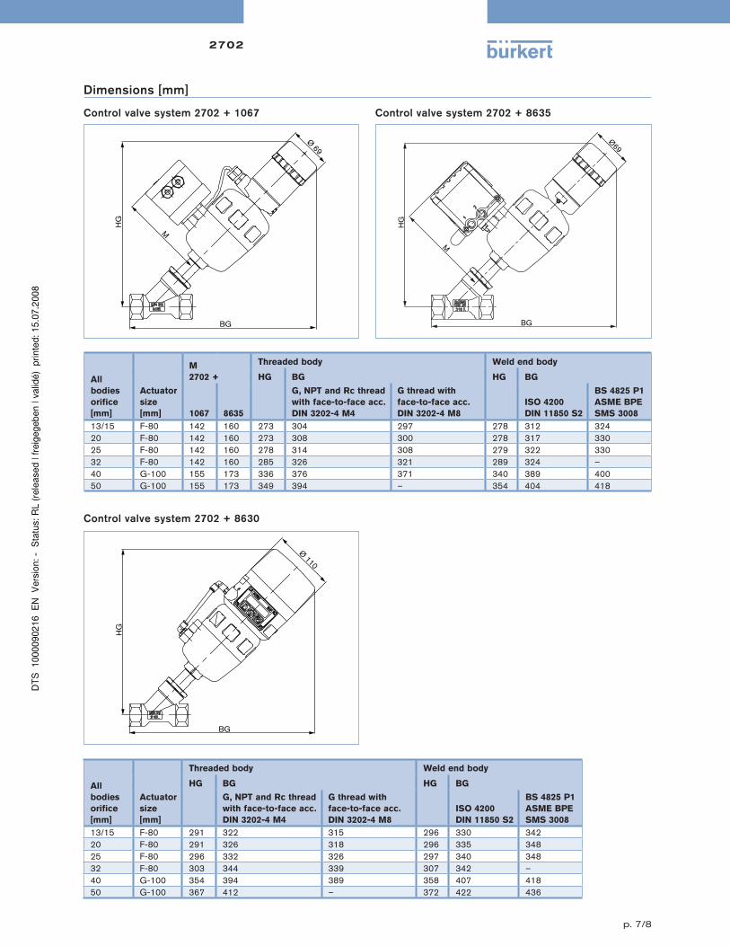
Dimensions[mm]
p. �/8
2702
Controlvalvesystem2702+1067
B¸rkertFluid Control Systems
D-74653 Ingelfingen
issue appl revision date design d.ctl stand q.ctl
date name
design
c.ctl
stand
q.ctl
dimensions wihout tolerances
linear dimensions
radii
angles
classification
scale
model
???
material
title
drawing no.
replaces
SW
sheet
2702 2702 BM03-2
Angle seat control valveSYST-2702-1067
- / -
with positioner Type 1067
11
04.09.2003
and position feedback
ma
of
HG
M
BG
Ø 69
Controlvalvesystem2702+8630
B¸rkertFluid Control Systems
D-74653 Ingelfingen
issue appl revision date design d.ctl stand q.ctl
date name
design
c.ctl
stand
q.ctl
dimensions wihout tolerances
linear dimensions
radii
angles
classification
scale
model
???
material
title
drawing no.
replaces
SW
sheet
2702 2702 BM02-2
Angle seat control valveSYST-2702-8630
- / -
with positioner Type 8630
11
09.09.200309.09.2003
ma
of
HG
Ø 110
BG
B¸rkertFluid Control Systems
D-74653 Ingelfingen
Ausg./Vers. Antrag ƒnderung Datum Gez. Gepr. Norm QS
Datum Name
Bearbeiter
Gepr¸ft
Norm
QS
Mafle ohne Toleranzangabe
L‰ngenmafle
Rundungshalbmesser
Winkelmafle
Klass-Nr.
Maflstab
Typ
Variantenst¸ckliste
Werkstoff
Benennung
Benennung
Ers.f.
SW
Blatt
2702 Z1-2702-003
Regelventil2702 und 8635
- / -
Darstellung ANTG F / DN25
11
17.06.2004 ma
von
HG
M
BG
Ø69
Dimensions[mm]
Allbodiesorifice [mm]
Actuatorsize [mm]
M 2702 +
Threaded body Weld end body
HG BG HG BG
1067 8635
G, NPT and Rc thread with face-to-face acc. DIN 3202-4 M4
G thread with face-to-face acc. DIN 3202-4 M8
ISO 4200 DIN 11850 S2
BS 4825 P1ASME BPE SMS 3008
13/15 F-80 142 160 273 304 297 278 312 32420 F-80 142 160 273 308 300 278 317 33025 F-80 142 160 278 314 308 279 322 33032 F-80 142 160 285 326 321 289 324 –40 G-100 155 173 336 376 371 340 389 40050 G-100 155 173 349 394 – 354 404 418
Allbodiesorifice [mm]
Actuatorsize [mm]
Threaded body Weld end body
HG BG HG BG
G, NPT and Rc thread with face-to-face acc. DIN 3202-4 M4
G thread with face-to-face acc. DIN 3202-4 M8
ISO 4200 DIN 11850 S2
BS 4825 P1ASME BPE SMS 3008
13/15 F-80 291 322 315 296 330 34220 F-80 291 326 318 296 335 34825 F-80 296 332 326 297 340 34832 F-80 303 344 339 307 342 –40 G-100 354 394 389 358 407 41850 G-100 367 412 – 372 422 436
Controlvalvesystem2702+8635

p. 8/8
2702
Incaseofspecialapplicationconditions,pleaseconsultforadvice.
Wereservetherighttomaketechnicalchangeswithoutnotice.
0701/0_US-en
Controlvalves–requestforquotation
PleasefilloutthisformandsendtoyourlocalBürkertfacility*withyourinquiryororder
Company Contactperson
Customerno. Department
Address Tel./Fax
Zipcode E-Mail
Type8635 - 2 wire
Standard EExia Powersupply24 VDC via setpoint or BUS Communication Setpoint/ output analog signal or via BUS Profibus PA Hart Positionerversion Input 4 - 20 mA Output 4 - 20mA or/and Binary PIDControllerversion3) Input measuring signal 4 - 20 mA Inductiveproximityswitch 1 2
Type1067
Valvemounted Remoteversion Powersupply24 VDC Communication Setpoint/ output analog signal
Positionerversion Input 0/4 - 20 mA / 0-10 V Output 4 - 20mA or Binary PIDControllerversion3) Input measuring signal 4 - 20 mA
Quantity Requireddeliverydate
Type8630- 3 wire
Powersupply24 VDC Communication Setpoint/ output analog signal or via BUS Profibus DP Device Net Positionerversion
Input 0/4 - 20 mA / 0 - 5/10 V Output 4 - 20mA or/and Binary
PIDControllerversion3) Input measuring signal
4 - 20 mA / Pt100 / FrequencyInductiveproximityswitch 1 2
3)samesetpointforInputandOutputsignalasforPositionerversion
2)Onlydiaphragmvalve
OperatingdataSiteofcontrol
Measuringandcontroltask
Pipeline DN PN
Pipematerial
Processmedium
Typeofmedia Liquid Steam Gas
Min Standard Max unit Flowrate(Q,QN,W)1)
TemperatureatvalveinletT1
AbsolutepressureatvalveinletP1
AbsolutepressureatvalveoutletP2
SteampressurePv
Kinematicviscosity(ν) mm2/s or cSt
Dynamicviscosity(η) mPa.s or cP
Standarddensity Kg/m3
Max.soundlevelaccepted dB (A)
ValvefeaturesControlvalvetype Globe Angle seat Diaphragm Ball valve Butterfly Other
Bodymaterial Stainless Steel PVC PP PVDF Other
Surfacefinish2) internal external
Seatsealingmaterial Metal PTFE EPDM2) FKM2)
Nominalpressure PN
Nominalsize DN
Typeofconnection Flange Socket union Welded Int. thread Ext. thread Tri-Clamp®
Standardconnection ISO DIN ANSI JIS Other
Function NC NO Double-acting
Pilotpressure min. max.
Positioner/Controller
=mandatoryfieldstofillout
1)standardunitLiquidQ=m3/h;SteamW=Kg/h;GasQN=Nm3/h
Note
You can fill out
the fields directly
in the PDF file
before printing
out the form.