222-s dmwsa improvement study library... · rpp-rpt-47179, rev. 0 3 executive summary ... 4.12...
TRANSCRIPT
RPP-RPT-47179, Rev. 0
222-S DMWSA Improvement Study
Larry McDanielARES Corporation for Washington River Protection Solutions, LLCRichland, WA 99352U.S. Department of Energy Contract DE-AC27-08RV1 4800
EDT/ECN: 607-623732- UC:Cost Center: Charge Code:B&R Code: Total Pages: 'IL
Key Words: 222-S, DMWSA Improvement Study, modifications, 222-S, Dangerous Mixed WasteStorage Area
Abstract: The 222-S Dangerous Mixed Storage Area Facility (DMWSA) is essential to supporting 222-SLaboratory analytical capabilities by temporarily storing low-level mixed waste. This study identifiespotential improvements and modifications necessary to ensure the DMWSA is capable of supporting futurestorage needs for the 222-S Laboratory. The facility and equipment improvements include budgetaryestimates adequate for a Baseline Change Request (BCR). The potential improvements include relocatingHVAC units, replacing the HVAC control system, modifyring container vents to eliminate moisterinfiltration, modifying a loading platform, performing corrosion prevention activities, adding additionalaccess to storage container HS-0083, increasing overall accessibility to the facility, upgrading the fireprotection system, improving waste segregation, replacing sump pump grates and providing additional wallshielding. The study also includes an assessment for facility replacement.
TRADEMARK DISCLAIMER. Reference herein to any specific commercial product, process, or service by trade name,trademark, manufacturer, or otherwise, does not necessarily constitute or imply its endorsement, recommendation, orfavoring by the United States Govemnment or any agency thereof or its contractors or subcontractors.
FEB 16 2011DATE: HANFORD
RELEASE I:
STA4( 17Releai Aproa Dfite Release Stamp
Approved For Public Release
A-6002-767 (REV 2)
RPP-RPT-47179, Rev. 0
2
222-S DMWSA IMPROVEMENT STUDY
September 2010
prepared by
ARES Corporation 1100 Jadwin Avenue, Suite 400 Richland, Washington 99352
(509) 946-3300
prepared for
Washington River Protection Solutions, LLC

RPP-RPT-47179, Rev. 0
3
EXECUTIVE SUMMARY
This study identifies potential improvements and modifications necessary to ensure the 222-S Dangerous and Mixed Waste Area (DMWSA) is capable of supporting future storage needs for the 222-S Laboratory. This Improvement Study is based on current requirements from the U.S. Department of Energy orders, Washington State regulations, applicable industry codes and standards, and feedback from facility personnel. This Improvement Study will serve as a technical basis for budget planning and budget submittal.
Constructed in the early 1950s, the 222-S Laboratory has provided analytical support for nearly 60 years to the Hanford mission and is planned to support the Waste Treatment Plant mission in future years. The DMWSA Facility, part of the 222-S Facility, temporarily stores radioactive, dangerous, mixed, and Polychlorinated biphenyl waste from the 222-S Laboratory. Waste is packaged into metal drums and stored inside one of two storage containers (HS-0082 and HS-0083) which make up the DMWSA Facility.
The approach in this Improvement Study is to identify and assess the improvements that should be implemented to support the 222-S Laboratory mission through fiscal year 2049. The potential improvements include relocating the heating, ventilation, and air conditioning units; replacing the heating, ventilation, and air conditioning control system; modifying container vents to eliminate moister infiltration; modifying a loading platform; performing corrosion prevention activities; adding additional access to storage container HS-0083; increasing overall accessibility to the facility; upgrading the fire protection system; improving waste segregation; and replacing sump pump grates and providing additional wall shielding. The study also includes an assessment for facility replacement.
This Improvement Study summarizes the description and assessment basis for each improvement. Many of the proposed improvements are necessary to maintain or improve the facility to operate safely and in compliance with current requirements, standards and practices for nuclear and hazardous waste storage. Some of the improvements will be required to meet anticipated future storage requirements.

RPP-RPT-47179, Rev. 0
4
TABLE OF CONTENTS
1.0 INTRODUCTION ...............................................................................................................7
2.0 PURPOSE AND SCOPE .....................................................................................................7 2.1 Project’s Charter ......................................................................................................7 2.2 Methodology ............................................................................................................8
3.0 BACKGROUND .................................................................................................................9 3.1 History and Description of the DMWSA.................................................................9
3.1.1 History.............................................................................................................9 3.1.2 Description ....................................................................................................11
4.0 POTENTIAL IMPROVEMENTS .....................................................................................12 4.1 Relocation of HVAC ..............................................................................................13 4.2 Upgrade HVAC Control System ...........................................................................13 4.3 Container Vents .....................................................................................................14 4.4 Loading Platform ...................................................................................................15 4.5 Corrosion................................................................................................................16 4.6 Door Opening.........................................................................................................16 4.7 Accessibility ...........................................................................................................17 4.8 Fire Protection ........................................................................................................17 4.9 Waste Segregation .................................................................................................18 4.10 Sump Pump Grates ................................................................................................18 4.11 Wall Shielding .......................................................................................................18 4.12 Permanent scaffolding and HVAC Cover ..............................................................19 4.13 Facility Replacement .............................................................................................19
5.0 IMPLEMENATION APPROACH ....................................................................................19 5.1 Upgrades Approach ...............................................................................................19 5.2 Cost Estimate .........................................................................................................19 5.3 Schedule .................................................................................................................20 5.4 Prioritization ..........................................................................................................20
6.0 RISK MANAGEMENT.....................................................................................................21 6.1 Risk Management/Uncertainty Analysis ...............................................................22 6.2 Uncertainty Analysis – Top 5 Upgrade/new facility Cost Estimates ....................23
7.0 OPEN ISSUES/PENDING DECISION ............................................................................23
8.0 FINAL UPGRADE PRIORITIZATION / NEW FACILITY EVALUATION / UNCERTAINTY ANALYSES .........................................................................................24
8.1 Final Prioritization Method, Inputs, and Results ...................................................24 8.2 New DMWSA Facility Evaluation ........................................................................28 8.3 Uncertainty Analysis Results .................................................................................29
9.0 REFERENCES ..................................................................................................................33
RPP-RPT-47179, Rev. 0
5
LIST OF APPENDICES
Appendix A
Appendix B
Appendix C
Appendix D
Appendix E
–
–
–
–
–
Estimates
Cost Estimate Basis
Risk Analysis
222-S DMWSA Improvement Sketches
Schedule
LIST OF FIGURES
Figure 3-1. 200 West Area. .............................................................................................................9
Figure 3-2. 222-S Site Plan. ..........................................................................................................10
Figure 3-3. DMWSA Layout. .......................................................................................................11
Figure 4-1. Roof Mounted HVAC Unit and Ducting. ..................................................................13
Figure 4-2. HVAC Controls. .........................................................................................................14
Figure 4-3. Container Vents. .........................................................................................................15
Figure 4-4. Loading Platform Covering........................................................................................16
Figure 4-5. Paint Chipping and Rust. ...........................................................................................16
Figure 4-6. DMWSA RFAR. ........................................................................................................17
Figure 4-7. Floor Sump and Grating. ............................................................................................18
Figure 6-1. Uncertainty Analysis Process. ....................................................................................23
Figure 8-1. Risk-Based Prioritization Method. .............................................................................25
Figure 8-2. CDF for Loading Platform, HVAC Control System, and Permanent Scaffolding and HVAC Cover. ..........................................................................................30
Figure 8-3. CDF for Sump Pump Grates. .....................................................................................31
Figure 8-4. CDF for Fire Protection. ............................................................................................32
Figure 8-5. CDF for New DMWSA Facility. ...............................................................................33
LIST OF TABLES
Table 5-1. Cost Estimate Summary. .............................................................................................20
Table 8-1. Upgrade Risk Reduction Summary Table. ..................................................................26
Table 8-2. New Facility Risk Reduction Summary Table. ...........................................................28
RPP-RPT-47179, Rev. 0
6
Abbreviations and Acronyms
AC Air conditioning CDF Cumulative Distribution Function CL Confidence Level DMWSA Dangerous Mixed Waste Storage Area DOE U.S. Department of Energy FY Fiscal Year PCB Polychlorinated biphenyl pdf Probability Density Function RFAR Radio Fire Alarm Reporter WRPS Washington River Protection Solutions, LLC
Units
ft feet gal gallon in. inch
RPP-RPT-47179, Rev. 0
7
1.0 INTRODUCTION
This study identifies and assesses potential improvements and modifications necessary to ensure the Dangerous and Mixed Waste Area (DMWSA) Facility is capable of supporting future temporary waste storage needs for the 222-S Laboratory. This Improvement Study is based on current requirements from the U.S. Department of Energy (DOE) orders, Washington State regulations, applicable industry codes and standards, and feedback from facility personnel. The Improvement Study will serve as a technical basis for budget planning and budget submittal.
This study includes the following appendices:
• Appendix A, “Estimates”;
• Appendix B, “Cost Estimate Basis”;
• Appendix C, “Risk Analysis”;
• Appendix D, “222-S DMWSA Improvement Sketches”; and
• Appendix E, “Schedule.”
2.0 PURPOSE AND SCOPE
The approach in this Improvement Study is to identify and assess the improvements that should be implemented to support the 222-S Laboratory mission through fiscal year 2049. This Improvement Study summarizes the description and assessment basis for each improvement, including facility replacement. Many of the proposed improvements are necessary to maintain or improve compliance with current requirements, standards and practices for nuclear and hazardous waste storage while other improvements will be required to meet anticipated future storage needs.
Detailed cost estimates of the improvements and renovations are provided in Appendix A. The Washington River Protection Solutions, LLC (WRPS) support costs by activity and the subcontracted costs for each activity are reflected in the estimates.
2.1 PROJECT’S CHARTER
The DMWSA Facility is located in the 200 West Area of Hanford within the 222-S Laboratory complex and consists of two storage modules identified as HS-0082 and HS-0083. The mission for the DWMSA Facility is to temporarily store radioactive, dangerous, mixed, and Polychlorinated biphenyl (PCB) waste from the 222-S Laboratory. Waste is packaged into metal drums and stored inside one of the two storage modules based on size, content, and available space. The waste stored in the DMWSA Facility is considered mixed (low level and hazardous) hazardous waste and is ultimately transferred to a treatment, storage, and/or disposal facility.

RPP-RPT-47179, Rev. 0
8
2.2 METHODOLOGY
The methodology used to prepare this document is listed below.
• A review of 222-S Laboratory documentation was performed to initiate a list of DMWSA improvements. A series of meetings were then held with facility personnel to review the list and identify any additional upgrades. The meetings were attended by 222-S Laboratory scientists, maintenance, operations, engineering, craft, and senior management. The potential improvements include relocating HVAC units, replacing the HVAC control system, modifying container vents, modifying a loading platform, performing corrosion prevention activities, adding additional access to the west ends of the facility, increasing overall accessibility to the facility, upgrading the fire protection system, improving waste segregation, replacing sump pump grates, providing additional wall shielding and facility replacement. See Section 4.0 for a detailed discussion of the DMWSA improvements.
• A risk analysis was performed which prioritized the necessary improvements according to its risk reduction potential/risk rank (see Appendix C). The risk analysis was performed to evaluate each potential upgrade to the existing DMWSA Facility as well as evaluate replacement of the entire facility.
• Rough-order-of-magnitude cost estimates and a high-level schedule were prepared for all the improvements identified. See Section 5.2 for cost summaries and Appendix E for the schedule. See Appendix A for the detailed cost estimates and Appendix B for the cost estimate basis.
• An evaluation and overall ranking of each upgrade was performed which resulted in a final prioritization based on the upgrade risk analysis, upgrade costs, schedule impacts, and other significant planning factors. The final prioritization is discussed in Section 8.1.
• An overall evaluation of the facility replacement improvement was performed based on risk reduction developed by comparing a new facility to an upgraded existing facility (i.e., assuming that all upgrades described in Section 4.0 are successfully completed), new facility costs, and other significant planning factors. The evaluation regarding facility replacement is documented in Section 8.2.

RPP-RPT-47179, Rev. 0
9
3.0 BACKGROUND
3.1 HISTORY AND DESCRIPTION OF THE DMWSA
3.1.1 History
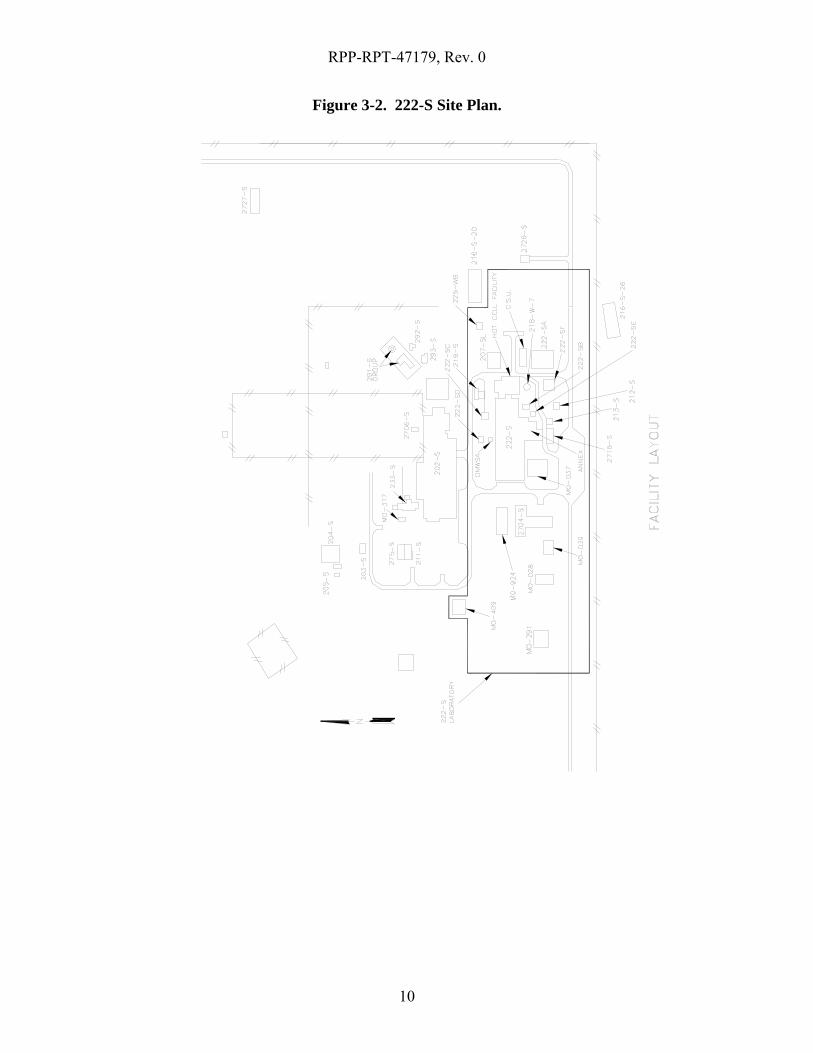
The 222-S Laboratory (Figures 3-1 and 3-2) has provided analytical support for nearly 60 years to the Hanford mission and is planned to support the Waste Treatment Plant mission in future years. It is anticipated that both 222-S and DMWSA will operate through the year 2049.
The DMWSA Facility, located north of the 222-S Laboratory, consists of two storage modules identified as HS-0082 and HS-0083. Waste that is generated from the 222-S Laboratory is considered low-level mixed waste and is packaged into metal drums. The drums remain in the DMWSA Facility temporarily until transferred to an onsite or offsite treatment, storage, and/or disposal facility.
Figure 3-1. 200 West Area.
RPP-RPT-47179, Rev. 0
10
Figure 3-2. 222-S Site Plan.
RPP-RPT-47179, Rev. 0
11
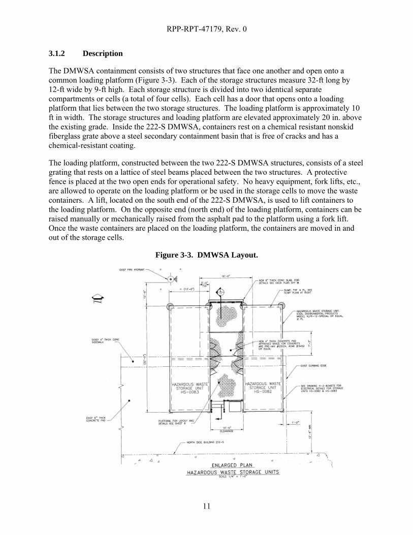
3.1.2 Description
The DMWSA containment consists of two structures that face one another and open onto a common loading platform (Figure 3-3). Each of the storage structures measure 32-ft long by 12-ft wide by 9-ft high. Each storage structure is divided into two identical separate compartments or cells (a total of four cells). Each cell has a door that opens onto a loading platform that lies between the two storage structures. The loading platform is approximately 10 ft in width. The storage structures and loading platform are elevated approximately 20 in. above the existing grade. Inside the 222-S DMWSA, containers rest on a chemical resistant nonskid fiberglass grate above a steel secondary containment basin that is free of cracks and has a chemical-resistant coating.
The loading platform, constructed between the two 222-S DMWSA structures, consists of a steel grating that rests on a lattice of steel beams placed between the two structures. A protective fence is placed at the two open ends for operational safety. No heavy equipment, fork lifts, etc., are allowed to operate on the loading platform or be used in the storage cells to move the waste containers. A lift, located on the south end of the 222-S DMWSA, is used to lift containers to the loading platform. On the opposite end (north end) of the loading platform, containers can be raised manually or mechanically raised from the asphalt pad to the platform using a fork lift. Once the waste containers are placed on the loading platform, the containers are moved in and out of the storage cells.
Figure 3-3. DMWSA Layout.

RPP-RPT-47179, Rev. 0
12
4.0 POTENTIAL IMPROVEMENTS
The upgrades will resolve the associated deficiencies identified to the DMWSA Facility listed below:
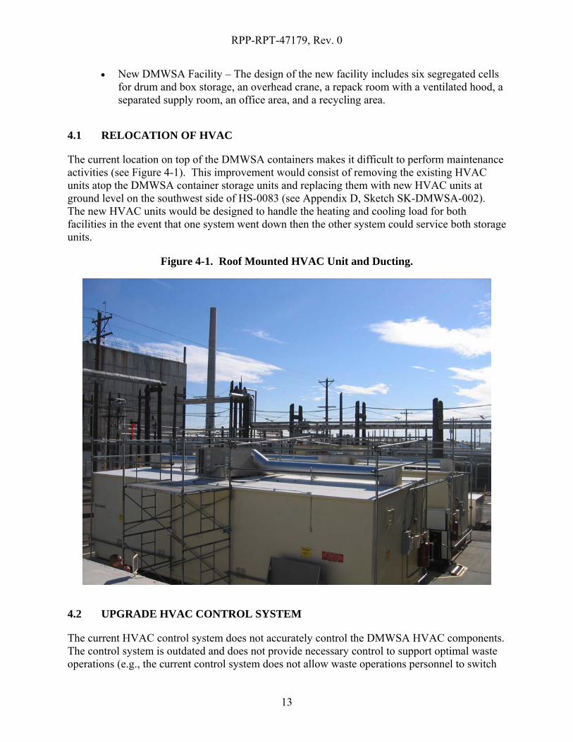
• Relocate HVAC units – The current location on top of the DMWSA containers makes it difficult to perform maintenance activities.
• Upgrade HVAC control system – The HVAC control system has problems switching between air conditioning (AC) and heat.
• Install fire damper covers – The fire damper vents are always open and lead to moisture intrusion.
• Improve loading platform – The loading platform between the units is a safety concern during inclement weather due to reduction in traction as there is insufficient drainage.
• Corrosion control – Rust is showing through the paint in spots.
• Door opening – Configuration does not allow a way to load in/out of a standard waste box (4’x4’x8’). Larger waste must be size reduced to fit in drums. Units are only intended for drums not larger than 85 gallons.
• Accessibility – Accessibility to the dock on the north side, intended for direct shipments, is hindered due to an old steam line pole.
• Fire Protection – The Radio Fire Alarm Repeater (RFAR) system is not linked to the main 222-S fire panel.
• Waste Segregation – Single sump for each cell requires portable containment for enhanced waste segregation.
• Sump pump grates – The current configuration of the main floor sump pump grates increases risk of injuries and reduces mobility with the drum cart feet.
• Shielding – Wall shielding/protection to the general workforce is limited to the configuration of metal drums inside HS-0082 and HS-0083 and the thin metal walls of the DMWSA Facility.
• Permanent scaffolding and HVAC cover – Prior to maintenance personnel performing maintenance on the HVAC units located on the roof of the DMWSA’s, the existing temporary scaffolding must be inspected. This adds additional craft personnel necessary to be scheduled before performing work. .
The other potential improvement includes complete DMWSA Facility replacement.
RPP-RPT-47179, Rev. 0
13
• New DMWSA Facility – The design of the new facility includes six segregated cells for drum and box storage, an overhead crane, a repack room with a ventilated hood, a separated supply room, an office area, and a recycling area.
4.1 RELOCATION OF HVAC
The current location on top of the DMWSA containers makes it difficult to perform maintenance activities (see Figure 4-1). This improvement would consist of removing the existing HVAC units atop the DMWSA container storage units and replacing them with new HVAC units at ground level on the southwest side of HS-0083 (see Appendix D, Sketch SK-DMWSA-002). The new HVAC units would be designed to handle the heating and cooling load for both facilities in the event that one system went down then the other system could service both storage units.
Figure 4-1. Roof Mounted HVAC Unit and Ducting.
4.2 UPGRADE HVAC CONTROL SYSTEM
The current HVAC control system does not accurately control the DMWSA HVAC components. The control system is outdated and does not provide necessary control to support optimal waste operations (e.g., the current control system does not allow waste operations personnel to switch
RPP-RPT-47179, Rev. 0
14
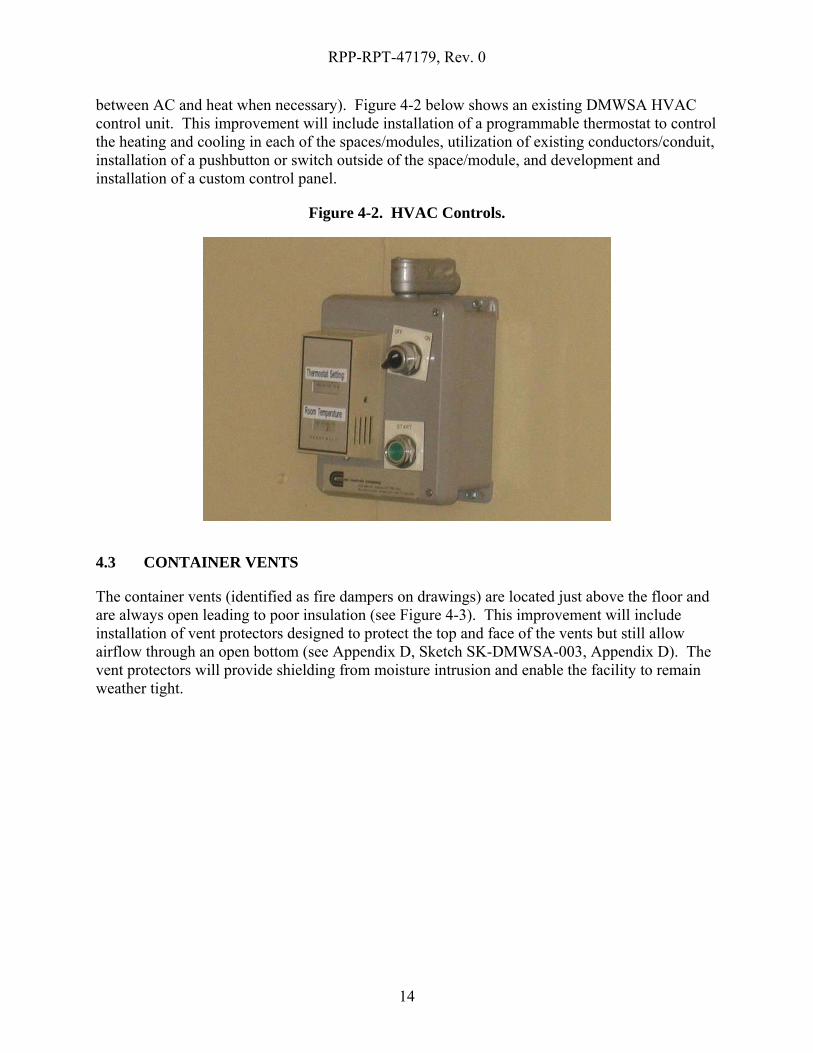
between AC and heat when necessary). Figure 4-2 below shows an existing DMWSA HVAC control unit. This improvement will include installation of a programmable thermostat to control the heating and cooling in each of the spaces/modules, utilization of existing conductors/conduit, installation of a pushbutton or switch outside of the space/module, and development and installation of a custom control panel.
Figure 4-2. HVAC Controls.
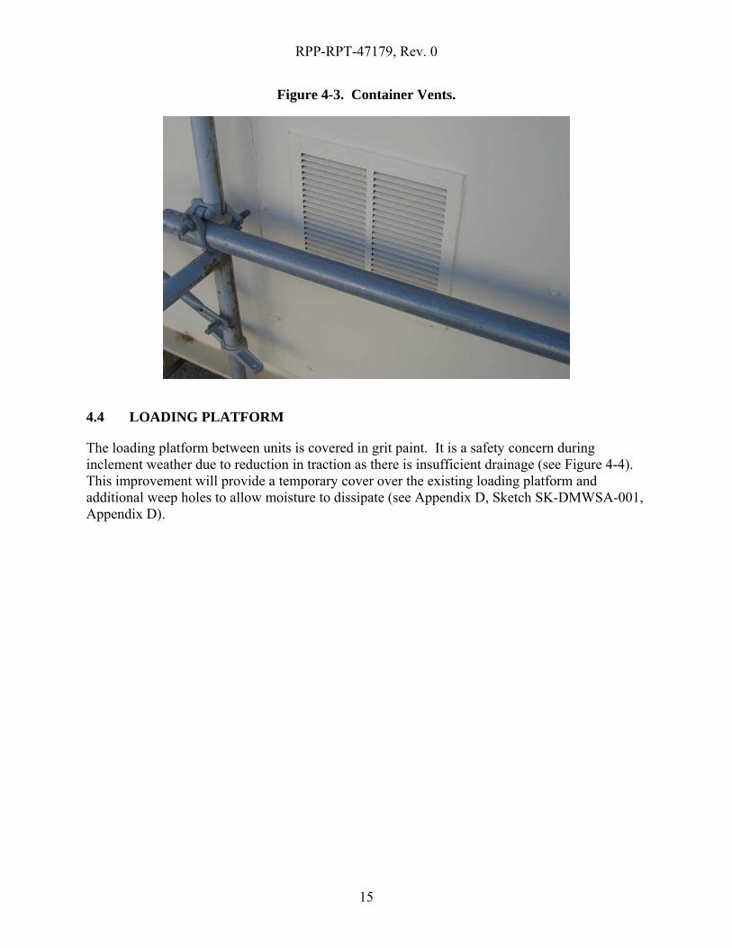
4.3 CONTAINER VENTS
The container vents (identified as fire dampers on drawings) are located just above the floor and are always open leading to poor insulation (see Figure 4-3). This improvement will include installation of vent protectors designed to protect the top and face of the vents but still allow airflow through an open bottom (see Appendix D, Sketch SK-DMWSA-003, Appendix D). The vent protectors will provide shielding from moisture intrusion and enable the facility to remain weather tight.
RPP-RPT-47179, Rev. 0
15
Figure 4-3. Container Vents.
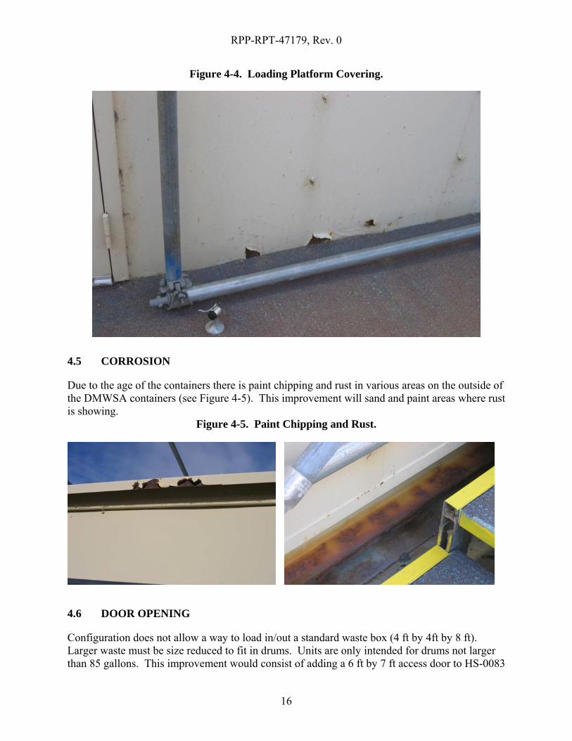
4.4 LOADING PLATFORM
The loading platform between units is covered in grit paint. It is a safety concern during inclement weather due to reduction in traction as there is insufficient drainage (see Figure 4-4). This improvement will provide a temporary cover over the existing loading platform and additional weep holes to allow moisture to dissipate (see Appendix D, Sketch SK-DMWSA-001, Appendix D).
RPP-RPT-47179, Rev. 0
16
Figure 4-4. Loading Platform Covering.
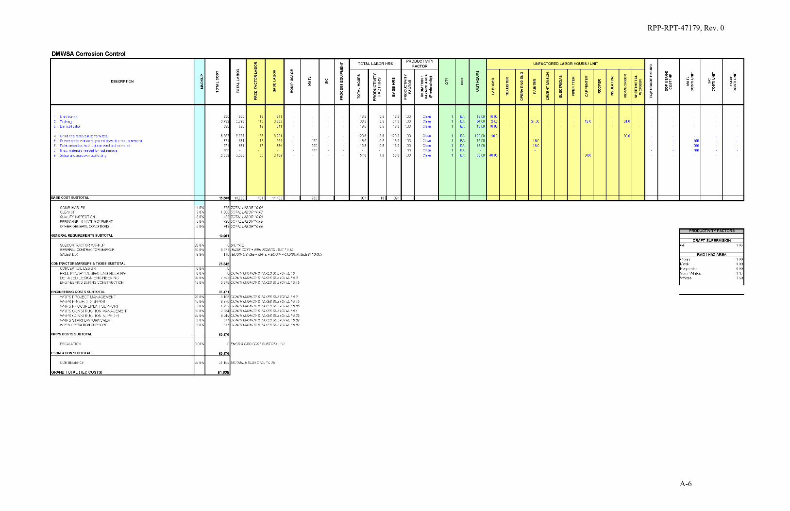
4.5 CORROSION
Due to the age of the containers there is paint chipping and rust in various areas on the outside of the DMWSA containers (see Figure 4-5). This improvement will sand and paint areas where rust is showing.
Figure 4-5. Paint Chipping and Rust.
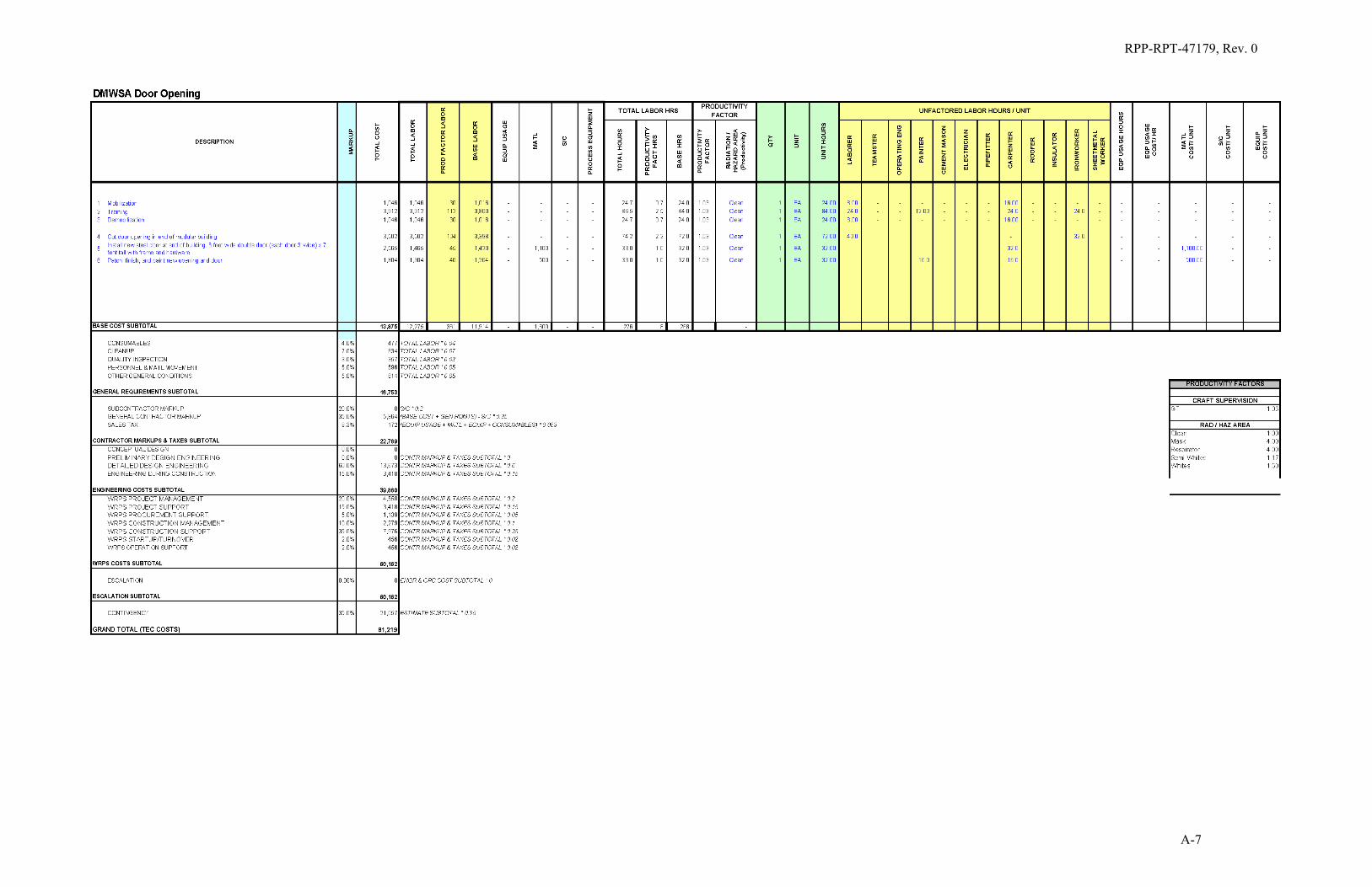
4.6 DOOR OPENING
Configuration does not allow a way to load in/out a standard waste box (4 ft by 4ft by 8 ft). Larger waste must be size reduced to fit in drums. Units are only intended for drums not larger than 85 gallons. This improvement would consist of adding a 6 ft by 7 ft access door to HS-0083
RPP-RPT-47179, Rev. 0
17
on the west end of the module. This improvement does not seem feasible given the current configuration of the existing facility and was not evaluated or ranked. However, the improvement was estimated and included in Table 5-1. The importance of the doors and the flexibility that larger doors would provide is considered in the risk reduction evaluation of a new facility, which would include a large door to accept standard waste boxes.
4.7 ACCESSIBILITY
Accessibility to the dock on the north side, intended for direct shipments, is hindered due to old steam line poles. Remove all of the obsolete steam line poles is due to be completed during the 222-S Facility Steam to Electric Heat Conversion Upgrade project during the FY 2011.
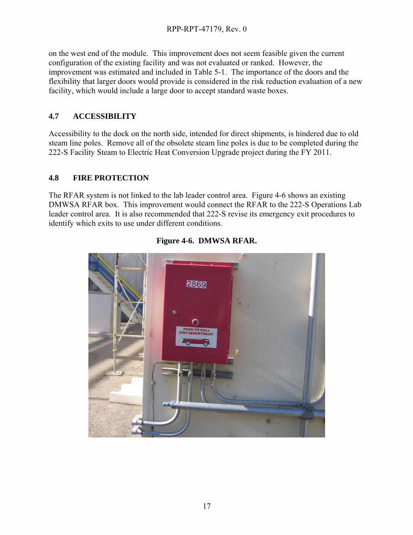
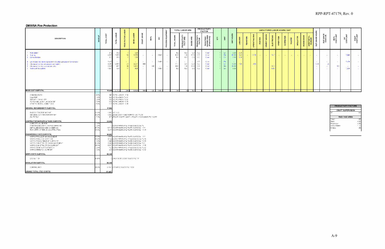
4.8 FIRE PROTECTION
The RFAR system is not linked to the lab leader control area. Figure 4-6 shows an existing DMWSA RFAR box. This improvement would connect the RFAR to the 222-S Operations Lab leader control area. It is also recommended that 222-S revise its emergency exit procedures to identify which exits to use under different conditions.
Figure 4-6. DMWSA RFAR.
RPP-RPT-47179, Rev. 0
18
4.9 WASTE SEGREGATION
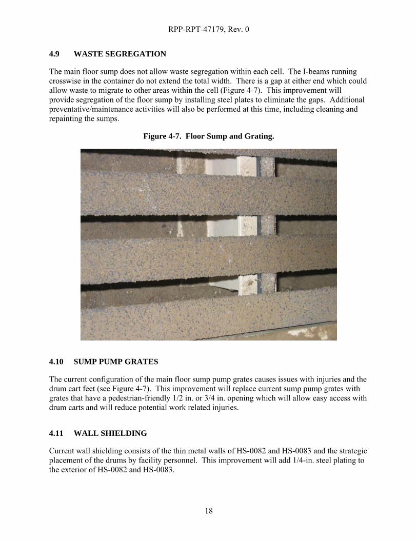
The main floor sump does not allow waste segregation within each cell. The I-beams running crosswise in the container do not extend the total width. There is a gap at either end which could allow waste to migrate to other areas within the cell (Figure 4-7). This improvement will provide segregation of the floor sump by installing steel plates to eliminate the gaps. Additional preventative/maintenance activities will also be performed at this time, including cleaning and repainting the sumps.
Figure 4-7. Floor Sump and Grating.
4.10 SUMP PUMP GRATES
The current configuration of the main floor sump pump grates causes issues with injuries and the drum cart feet (see Figure 4-7). This improvement will replace current sump pump grates with grates that have a pedestrian-friendly 1/2 in. or 3/4 in. opening which will allow easy access with drum carts and will reduce potential work related injuries.
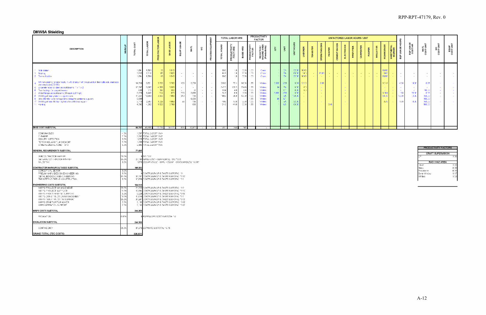
4.11 WALL SHIELDING
Current wall shielding consists of the thin metal walls of HS-0082 and HS-0083 and the strategic placement of the drums by facility personnel. This improvement will add 1/4-in. steel plating to the exterior of HS-0082 and HS-0083.

RPP-RPT-47179, Rev. 0
19
4.12 PERMANENT SCAFFOLDING AND HVAC COVER
Prior to maintenance personnel performing maintenance on the HVAC units located on the roof of the DMWSA’s, the existing temporary scaffolding must be inspected. This adds additional craft personnel necessary to be scheduled before performing work. This improvement will install permanent roof access structure with stairs along side the DMWSA’s. The structure will include a roof which covers the structure and the HVAC units. This will provide some measure of protection from the elements for maintenance personnel. See Figure 4.1 for existing scaffolding and DMWSA roof.
4.13 FACILITY REPLACEMENT
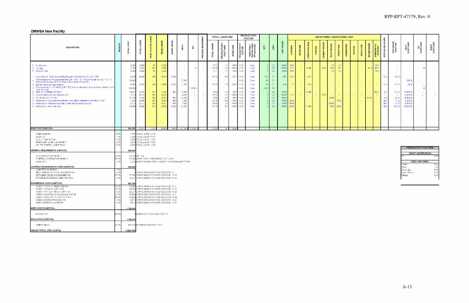
The study looked at the cost and risk reduction associated with replacing the DMWSA Facility with a new facility to meet long-term needs and requirements. A brainstorming session identified a new DMWSA layout and associated features. A sketch which shows the proposed layout and location is provided in Appendix D (Sketches SK-DMWSA-004 and SK-DMWSA-005). The design of the new DMWSA Facility includes six segregated cells for drum and box storage, an overhead crane, a repack room with a ventilated hood, a separated supply room, an office area, and a recycling area. The new DMWSA Facility will be 36 ft by 70 ft to 20-ft high to support the overhead crane. Facility access from 222-S will be through door 15. 222-SH activities will be relocated to accommodate the new facility.
5.0 IMPLEMENATION APPROACH
5.1 Upgrades Approach
All upgrades have been determined to be expense-funded projects. For planning purposes, it is expected that construction work will be performed by one of the on-site construction contractors.
5.2 Cost Estimate
The upgrade cost estimates were developed from the input and decisions made from meetings held with WRPS facility personnel. The Permanent Scaffolding and HVAC cover estimate was developed as an additional upgrade identified during final review of the study. See Table 5-1 for the cost estimate summary for each of the planned upgrades. See Appendix A for detailed cost estimate information.

RPP-RPT-47179, Rev. 0
20
Table 5-1. Cost Estimate Summary.
No. Upgrade Description Estimate (TPC)
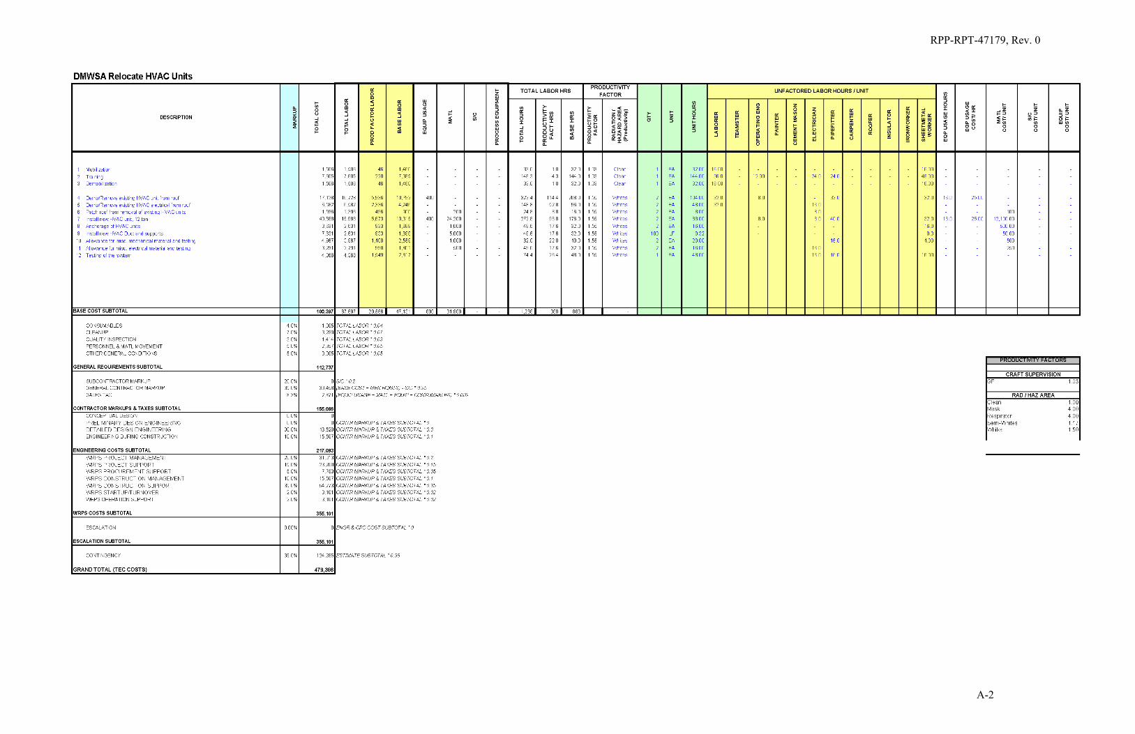
1 HVAC Units $479,386
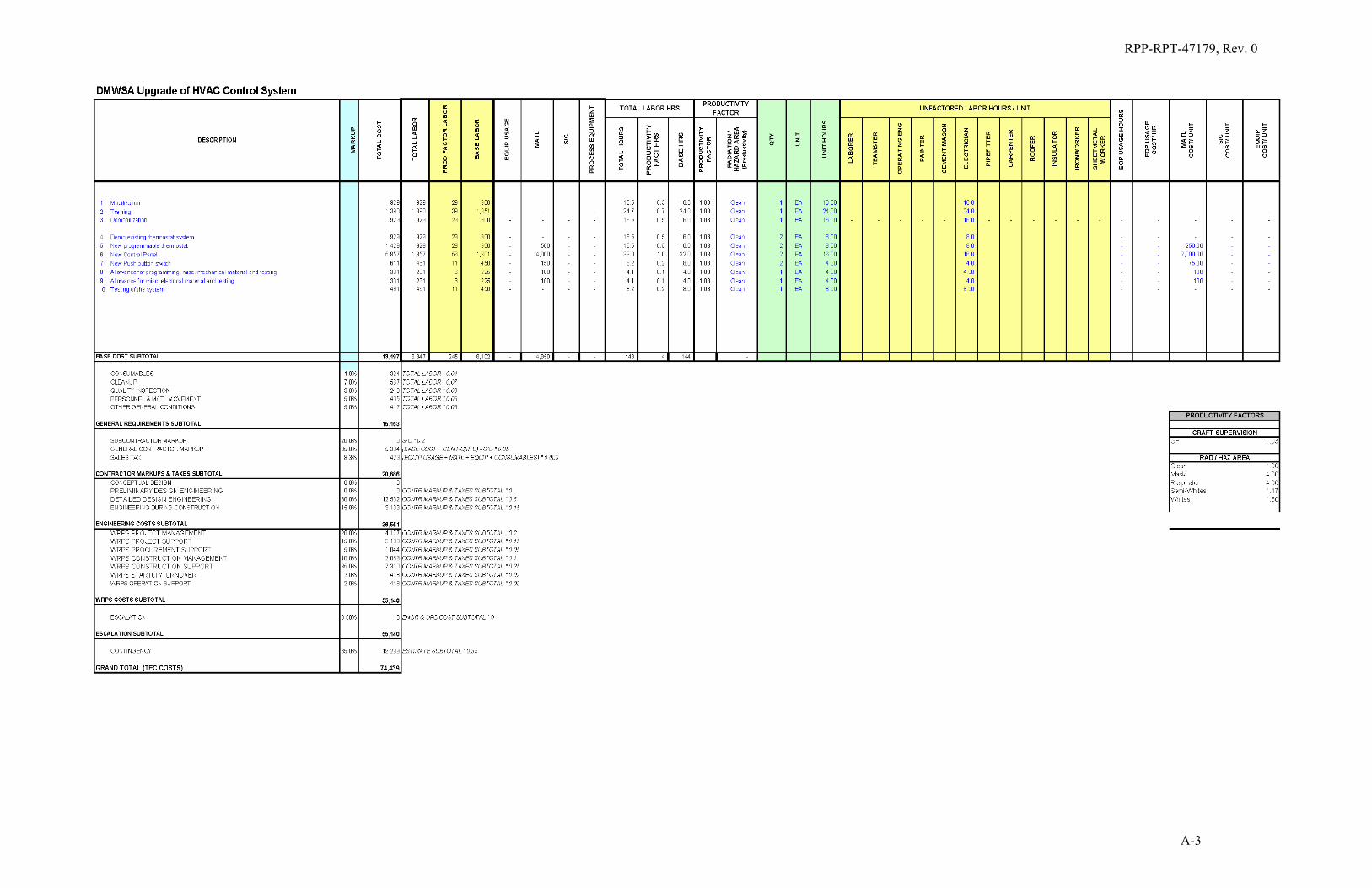
2 HVAC Control Units $74,439
3 Fire Damper Covers $48,978
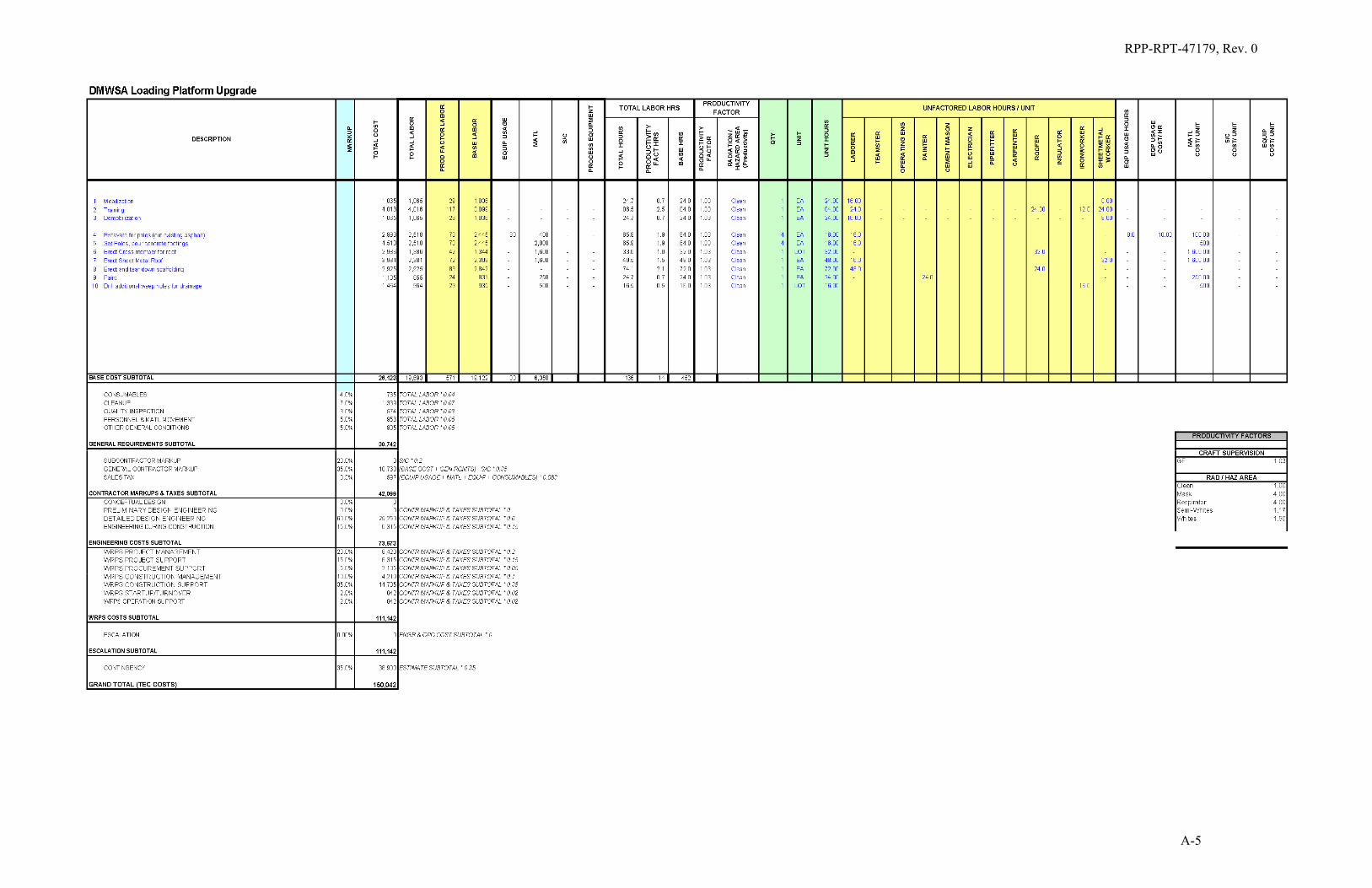
4 Loading Platform $150,042
5 Corrosion $81,635
6 Door Openings $81,219
7 Accessibility $0
8 Fire Protection $81,467
9 Waste Segregation $239,684
10 Sump Pump Grates $264,103
11 Shielding $336,631
12 Permanent Scaffolding & HVAC Cover $274,307
13 New Facility $1,553,734
TPC = Total Project Cost
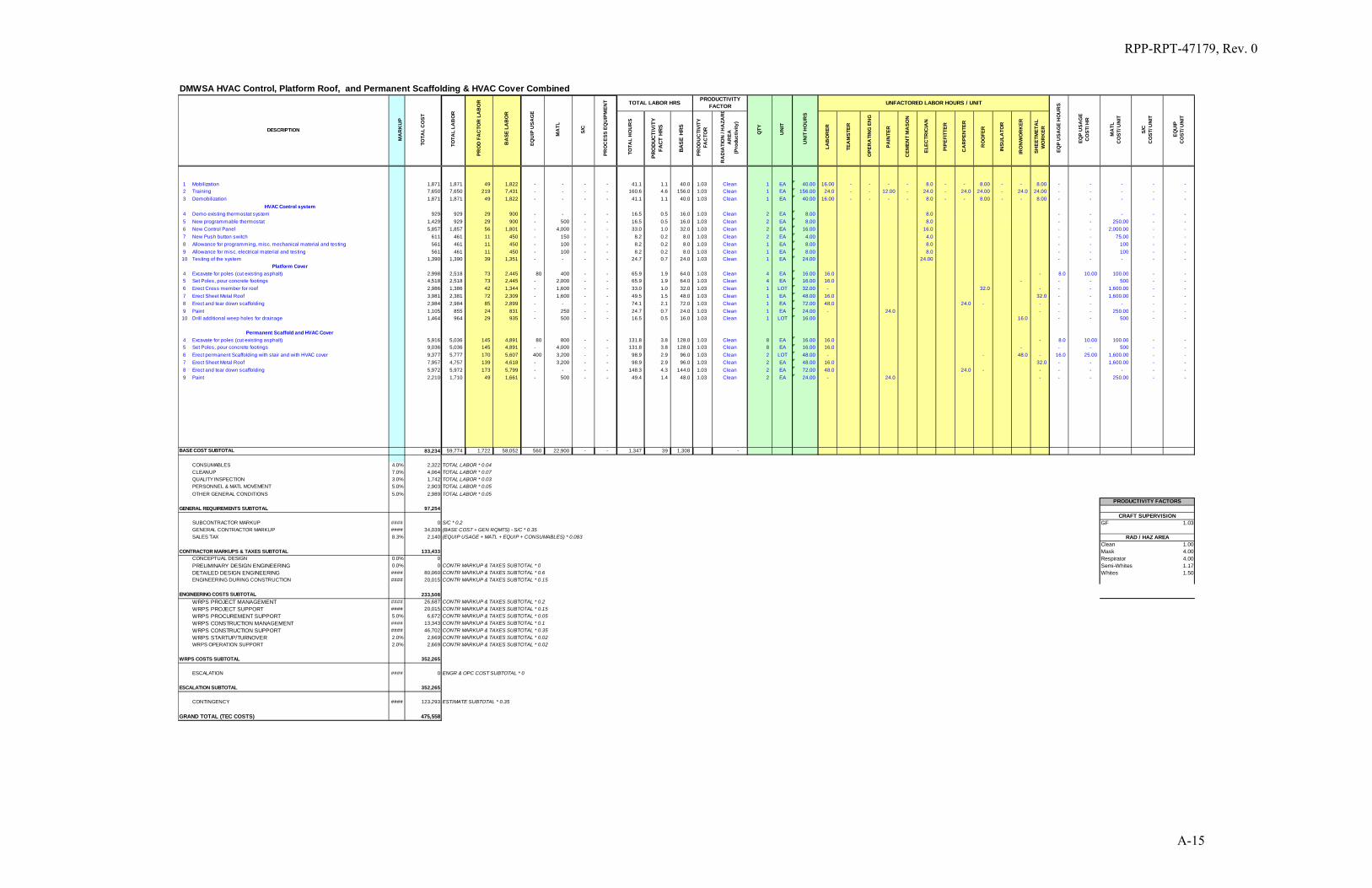
A combined estimate was developed for upgrades 2, 4, and 12. This was based on funding constraints in FY11. The estimate for the combined upgrades of 2, 4, and 12 is $475,558.
See Appendix B for the Cost Estimate Basis.
5.3 SCHEDULE
The schedule is provided in Appendix E. The logic in the schedule was developed using a cost profile of $450K per year available for the upgrades. The schedule reflects the combined upgrades selected for FY11 based on funding constraints.
5.4 PRIORITIZATION
A risk-based priority analysis was performed on the upgrades proposed for the DMWSA Facility and on the facility replacement improvement. The analysis method is consistent with DOE G 413.3-7, Risk Management Guide. The approach was to evaluate each improvement for the potential to reduce the 222-S Laboratory’s risk based on nine major risk categories. A facilitated session was conducted with 222-S Laboratory Subject Matter Experts and management staff to fully explore the potential for risk reduction that each improvement might offer. Numerical scores were developed to represent risk reduction potential. DMWSA Facility upgrades with higher potential for risk reduction received higher scores and higher rankings than those having less potential for risk reduction. The facility replacement improvement evaluation focused on risk reduction based on comparing a new facility to an upgraded existing facility (i.e.,

RPP-RPT-47179, Rev. 0
21
assuming that all upgrades described in Section 4.0 are successfully completed). This comparison was done to identify long-term risk reduction and flexibility associated with a new facility, even if the potential near-term upgrades (essentially maintenance activities) are completed. The risk analysis is contained in Appendix C. The permanent scaffolding and HVAC cover items were developed in response to the final review of this study and therefore were not included in the risk analysis.
Furthermore, the upgrades and facility replacement improvement were evaluated based on comparison of risk-reduction, total cost, schedule impacts, and on the inclusion of other significant planning factors. The results of the upgrade final prioritization are described in Section 8.1 and the new facility evaluation is documented in Section 8.2.
6.0 RISK MANAGEMENT
TFC-PLN-39, “Risk Management Plan,” describes the systematic process used to assess and manage project risks for WRPS within the River Protection Plan managed by the DOE Office of River Protection.
At the WRPS company level, the result of the risk planning process is the Tank Farms Operations Contract Risk Management Plan. At the work area or individual project level, the result of the risk planning process may be a project Risk Management Plan, a Risk and Opportunity Assessment Report, or an explanation of project risk management in a project-level project execution plan. The activities of each of the risk management components may be tailored during project planning for the specific needs of each Risk and Opportunity Assessment. Planning activities may include, but are not limited to the following:
• Identifying objectives, scope, assumptions, and constraints;
• Establishing an organizational structure (risk assessment Integrated Project Team); and
• Defining personnel responsibilities.
As the 222-S DMWSA Facility upgrades are planned and implemented, individual sub-project risks, constraints, and enabling assumptions will be identified, evaluated, and controlled in accordance with TFC-PRJ-PC-C-13, “Risk Management.” Work execution level risks will be identified as they manifest and any mitigation actions discussed at project status meetings, documented in project meeting minutes, tracked in the integrated schedule as needed, and managed by the project manager and Integrated Project Team. The 222-S Laboratory is an operating laboratory and planning will include methods to minimize impact to ongoing operations. There is a near-term window of approximately ten years before the workload significantly increases to support retrievals and transfers to the WTP and Supplemental Treatment Facilities. Opportunities for completion of 222-S DMWSA Facility upgrades should be maximized during this near-term window.
RPP-RPT-47179, Rev. 0
22
6.1 RISK MANAGEMENT/UNCERTAINTY ANALYSIS
Quantitative estimate analyses are used to identify specific cost risks throughout the life of a project. Uncertainty analyses are part of risk management implementation, as cost risks often require further evaluation beyond the qualitative risk management process. Specifically, TFC-PRJ-PC-C-13, describes requirements for Work Area Managers, Task Project Managers, and other responsible managers to conduct project level risk assessments and residual uncertainty analyses using Monte Carlo techniques (or equivalent) for developing a basis for management reserve/contingency values and significant project baseline changes. Additionally, quantitative focus on cost risks is appropriate because costs often define success relative to project management. Given that the risk assessment process is largely qualitative, the real potential benefit of an uncertainty analysis is to provide a quantitative measure of the potential impact of a particular risk item or project activity.
Although the current 222-S DMWSA improvement study phase does not necessarily warrant an uncertainty analysis as described in TFC-PRJ-PC-C-13, it was determined to apply the uncertainty analysis process to the five highest priority upgrades (i.e., the high-priority upgrades accompanying cost estimates) and the new facility improvement cost estimate. The uncertainty analyses regarding these improvements, although performed using subjective assumptions and uncertainty distributions, were performed to provide a better overall understanding of the impacts of project uncertainties related to a particular cost estimate. The general uncertainty analysis process used to evaluate the five highest priority upgrade estimates and the new facility estimate is described below.
Uncertainty, based on risk information, with respect to cost element estimates are defined in terms of probability density functions. The uncertainty probability density functions are then propagated through project media with respect to the cost estimate using Monte Carlo convolution techniques. Uncertainty-based analyses determine the impacts to the project from uncertainty associated with risk impacts and project planning data. Uncertainty analyses are performed using the methodology described above and shown in Figure 6-1.

RPP-RPT-47179, Rev. 0
23
Figure 6-1. Uncertainty Analysis Process.
6.2 UNCERTAINTY ANALYSIS – TOP 5 UPGRADE/NEW FACILITY COST ESTIMATES
An initial cost estimate uncertainty analysis was performed in conjunction with development of the five highest priority upgrades cost estimates and the new facility improvement cost estimate. These uncertainty analysis results are shown in Section 8.3.
7.0 OPEN ISSUES/PENDING DECISION
None.
RPP-RPT-47179, Rev. 0
24
8.0 FINAL UPGRADE PRIORITIZATION / NEW FACILITY EVALUATION / UNCERTAINTY ANALYSES
As discussed in early sections, the Facility upgrades were evaluated with respect to risk reduction, cost comparison, schedule logistics, and consideration of other significant planning factors in order to determine a final upgrade prioritization. The final upgrade prioritization differentiates the five highest priority upgrades as upgrades this study recommends be completed in a timely manner to maintain or improve the Facility. These five upgrades serve to ensure 222-S DMWSA Facility operates safely and in compliance with current requirements, standards, and practices for nuclear and hazardous waste storage. Section 8.1 describes the final prioritization method, inputs, and results. Although upgrades related to permanent scaffolding and HVAC cover were only identified during final review of this study, they were included in the final prioritization. These items were determined to be high in priority based on practical planning logistics/factors described in Section 8.1.
Also described in previous sections, an overall evaluation of the facility replacement improvement was performed based on risk reduction developed by comparing a new facility to an upgraded existing facility, new facility costs, and other significant planning factors. Section 8.2 documents this evaluation.
The uncertainty analysis results for the five highest priority upgrade cost estimates and the new facility cost estimate are illustrated in Section 8.3.
8.1 FINAL PRIORITIZATION METHOD, INPUTS, AND RESULTS
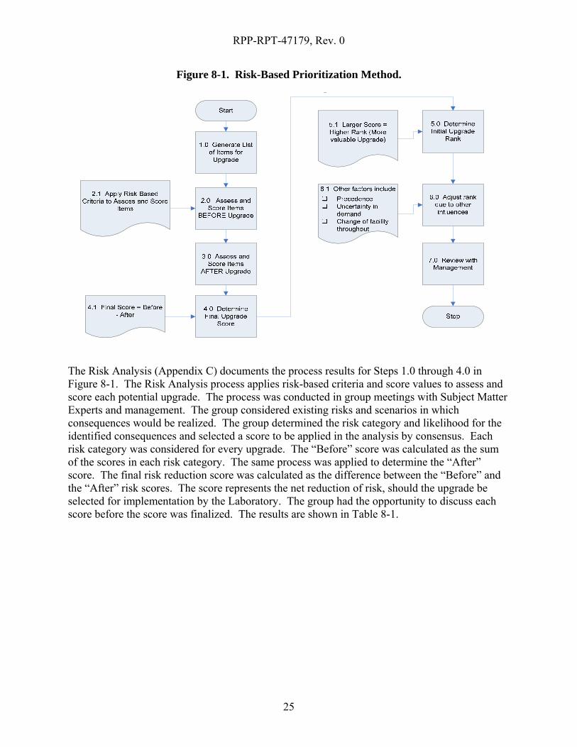
The prioritization method was developed to adjust risk rankings to account for cost, precedence, and other significant planning factors to ultimately rank upgrades. The method is shown in Figure 8-1.
RPP-RPT-47179, Rev. 0
25
Figure 8-1. Risk-Based Prioritization Method.
The Risk Analysis (Appendix C) documents the process results for Steps 1.0 through 4.0 in Figure 8-1. The Risk Analysis process applies risk-based criteria and score values to assess and score each potential upgrade. The process was conducted in group meetings with Subject Matter Experts and management. The group considered existing risks and scenarios in which consequences would be realized. The group determined the risk category and likelihood for the identified consequences and selected a score to be applied in the analysis by consensus. Each risk category was considered for every upgrade. The “Before” score was calculated as the sum of the scores in each risk category. The same process was applied to determine the “After” score. The final risk reduction score was calculated as the difference between the “Before” and the “After” risk scores. The score represents the net reduction of risk, should the upgrade be selected for implementation by the Laboratory. The group had the opportunity to discuss each score before the score was finalized. The results are shown in Table 8-1.

RPP-RPT-47179, Rev. 0
26
Table 8-1. Upgrade Risk Reduction Summary Table.
Risk Rank Priority Potential Improvement Description Risk Reduction
Score
1 Loading Platform Provide roof over loading platform and re-drill weep holes. 136
2 Sump Pump Grates Replace current grating configuration with new grating that will not cause injuries or interfere with drum cart feet.
129
3 Fire Protection Provide signal to main 222-S fire panel. 121
4 Accessibility
Remove Steam line. Steam line is being removed by the 222-S Steam to Electric Conversion Project. To be completed in FY 2011.
115
5 HVAC Control System Provide new ventilation control with manual switch located on outside of DMWSA. 90
6 HVAC Units Relocate HVAC units to ground level. 70
7 Wall Shielding Provide additional shielding by installing 1/4-in. steel plate on outside of DMWSAs. 56
8 Waste Segregation Seal ends of I-beams beneath grating to provide sump waste segregation within cell. 13
9 Fire Damper Covers Provide outside cover to prevent moisture intrusion. 11
10 Corrosion Sand and repaint. 1
Note: As described in Section 4.6, the Door Opening improvement was not evaluated from a risk-reduction perspective.
After the risk scores for each of the upgrades were determined, other factors such as cost and practical planning logistics were considered to support final prioritization. Practical planning factors may change the relative desirability or practicality of certain activities beyond the risk scoring provided by the Risk Analysis. Examples of planning factors that may merit adjustments in priority include:
• Changes in the expected life of a site or facility;
• Changes to site or facility mission;
• Management workloads and the ability to provide adequate management to the activity or upgrade;
• Staff workloads and the ability to obtain qualified staff;
• Uncertainties in requirements;
• Uncertainties in obtaining project benefits; and
• Perception of site or facility risks by the public or other external stakeholders.

RPP-RPT-47179, Rev. 0
27
Finally, the upgrades were evaluated against schedule impacts and/or schedule logistics to help prioritize the upgrades from a schedule feasibility perspective.
Many upgrades and potential upgrade scenarios were compared in terms of net risk reduction, cost, schedule impacts, and other significant planning factors. The assessment teams were afforded an interactive opportunity to interpret the scope of the upgrades and to perform more in-depth analysis on a few upgrades, where appropriate. The following final prioritization includes upgrades that are relevant to the most cost-effective and feasible efforts to reduce the impacts and/or likelihoods of significant Facility risks.
1. Loading Platform – Provide roof over loading platform and re-drill weep holes.
2. HVAC Control System – Provide new ventilation control with manual switch located on outside of DMWSA
3. Permanent Scaffolding and HVAC cover - Install permanent scaffolding with a cover to allow access to the HVAC units. In addition, install a cover over the HVAC units.
4. Sump Pump Grates – Replace current grating configuration with new grating that will not cause injuries or interfere with drum cart feet.
5. Fire Protection – Provide signal to main 222-S fire panel.
6. Wall Shielding – Provide additional shielding by installing 1/4-in steel plate on outside of the DMWSAs.
7. Waste Segregation – Seal ends of I-beams beneath grating to provide sump waste segregation within cell.
8. Fire Damper Covers – Provide outside cover to prevent moisture intrusion.
9. Corrosion – Sand and repaint.
10. HVAC Units – Relocate HVAC units to ground level.
11. Accessibility – Remove steam line. Steam line is being removed by the 222-S Steam to Electric Conversion Project - to be completed in FY 2011.
The Accessibility upgrade was considered lowest priority because the steam line is being removed by the 222-S Steam to Electric Conversion Project—to be completed in FY 2011.
Given all of the prioritization factors discussed above, upgrades 1 through 5 (bolded) were determined to be the highest priority. That is not to say that the lower prioritized upgrades should be excluded from consideration; these lower priority upgrades may be associated with changing future objectives or other factors that cannot be quantified at the time of this study.

RPP-RPT-47179, Rev. 0
28
8.2 NEW DMWSA FACILITY EVALUATION
The evaluation method was based on identifying possible risk reduction associated with a new facility relative to an upgraded existing facility. Once the risk reduction was determined, new facility costs and other significant planning factors were considered to better understand the possible benefits and impacts of a new facility. This evaluation method is similar to the method shown in Figure 8-1 only there was no need to rank the new facility against the upgrades to the existing facility. The value of this evaluation is to identify and understand the long-term risk reduction and flexibility associated with a new facility, even if the potential near-term upgrades are completed.
The Risk Analysis (Appendix C) documents large risk reduction associated with a new facility. The 222-S Evaluation team considered existing risks and scenarios in which consequences would be realized. As for the upgrades described in Section 8.1, the group determined the risk category and likelihood for the identified consequences and selected a score to be applied in the analysis by consensus. The “Before” score represented an upgraded existing facility (i.e., assuming that all upgrades described in Section 4.0 are successfully completed) then an “After” score reflected a new facility. The final risk reduction score was calculated as the difference between the “Before” and the “After” risk scores. The score represents the net reduction of risk, should a new facility replace an upgraded existing facility. The group had the opportunity to discuss each score before the score was finalized. The results are shown in Table 8.2.
Table 8-2. New Facility Risk Reduction Summary Table.
Risk Rank
Priority Potential Improvement Description
Risk Reduction
Score Not
Applicable
New Facility Consolidate DMWSA activities to a single building outside door 16. 321
After the risk scores for each of the upgrades were determined, other factors such as cost and practical planning logistics were considered. The following factors were particularly significant in evaluating a new facility:
• Changes in the expected life of a site or facility;
• Changes to site or facility mission; and
• Uncertainties in obtaining project benefits.
As a result of this evaluation it was determined that a new facility provides cost-effective risk reduction significant enough to continually consider facility replacement a logical and optimal 222-S DMWSA Facility improvement. A new facility would provide significantly more flexibility and capability regarding waste acceptance, segregation, control, and shipment. Furthermore, a new facility provides enough space to contain waste management equipment, containers, and work space associated with safely performing waste management activities
RPP-RPT-47179, Rev. 0
29
efficiently. The existing facility and waste management processes require workers to navigate (often with forklifts) completely around the north side of 222-S to move and collect waste. These movements would be eliminated by a new facility. Finally, the cost of the new facility is relatively low compared to the upgrades identified in this document and future upgrades and inefficiencies associated with continuing the DMWSA facility as currently configured.
8.3 UNCERTAINTY ANALYSIS RESULTS
The risk-based uncertainty analyses process that was described in Sections 6.1 and 6.2 starts by removing all contingency from the estimate. Next, the process progresses by identifying cost uncertainties associated with cost estimate line items and identified project risks.
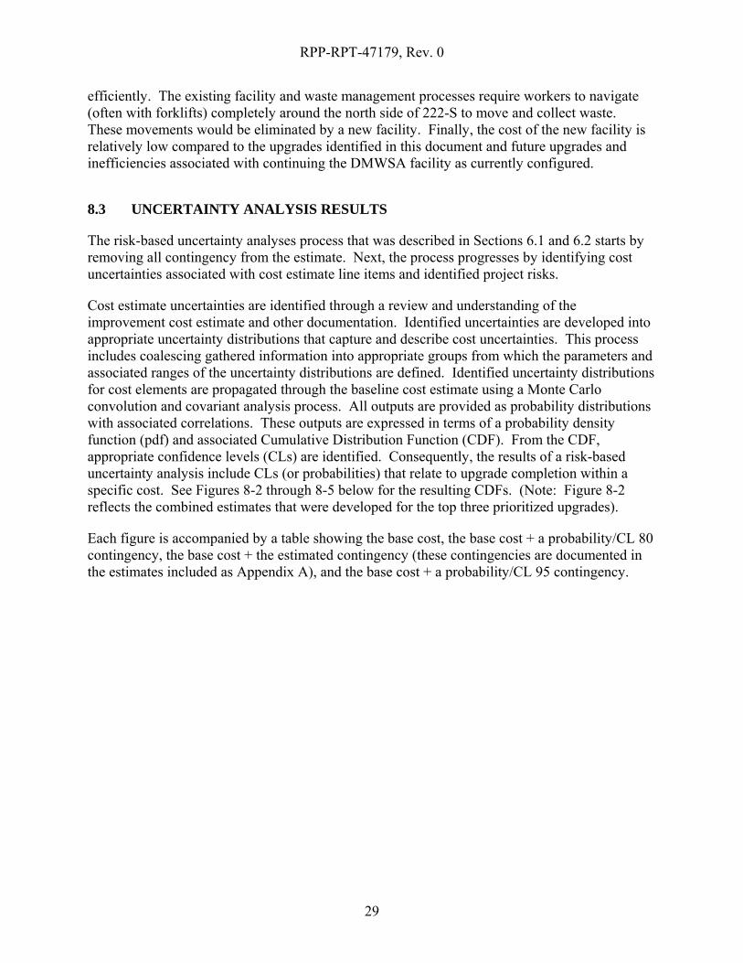
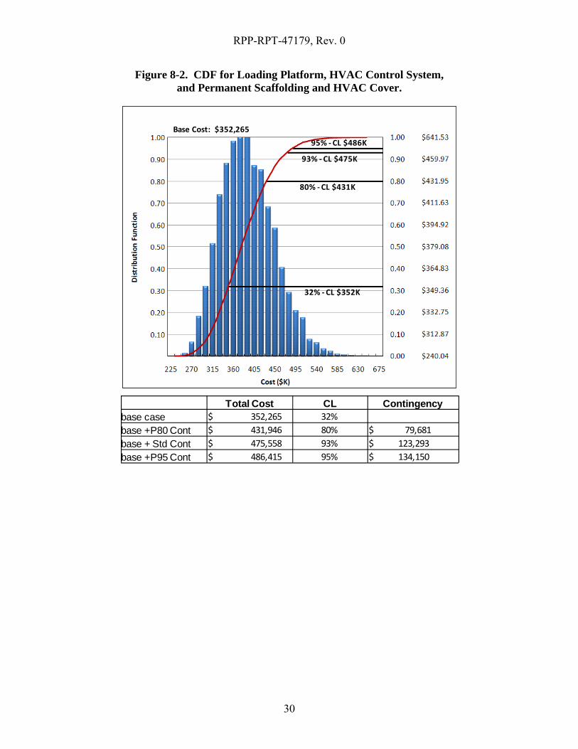
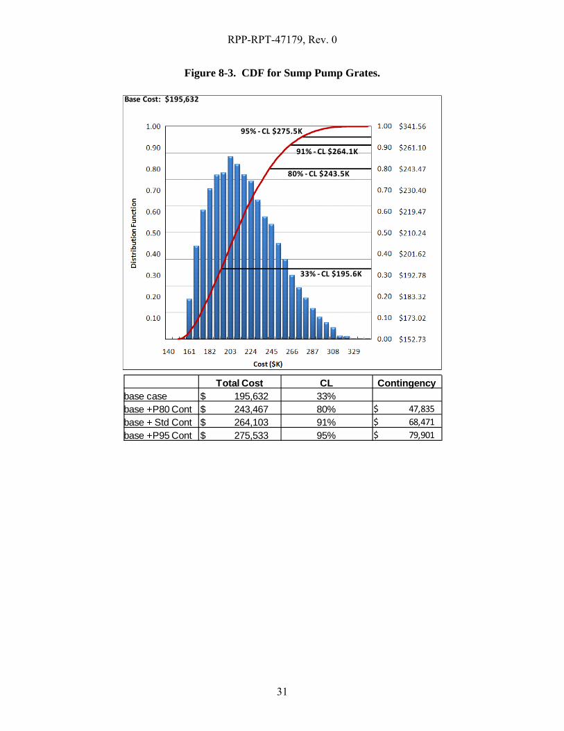
Cost estimate uncertainties are identified through a review and understanding of the improvement cost estimate and other documentation. Identified uncertainties are developed into appropriate uncertainty distributions that capture and describe cost uncertainties. This process includes coalescing gathered information into appropriate groups from which the parameters and associated ranges of the uncertainty distributions are defined. Identified uncertainty distributions for cost elements are propagated through the baseline cost estimate using a Monte Carlo convolution and covariant analysis process. All outputs are provided as probability distributions with associated correlations. These outputs are expressed in terms of a probability density function (pdf) and associated Cumulative Distribution Function (CDF). From the CDF, appropriate confidence levels (CLs) are identified. Consequently, the results of a risk-based uncertainty analysis include CLs (or probabilities) that relate to upgrade completion within a specific cost. See Figures 8-2 through 8-5 below for the resulting CDFs. (Note: Figure 8-2 reflects the combined estimates that were developed for the top three prioritized upgrades).
Each figure is accompanied by a table showing the base cost, the base cost + a probability/CL 80 contingency, the base cost + the estimated contingency (these contingencies are documented in the estimates included as Appendix A), and the base cost + a probability/CL 95 contingency.
RPP-RPT-47179, Rev. 0
30
Figure 8-2. CDF for Loading Platform, HVAC Control System, and Permanent Scaffolding and HVAC Cover.
Total Cost CL Contingencybase case $ 352,265 32%base +P80 Cont $ 431,946 80% $ 79,681 base + Std Cont $ 475,558 93% $ 123,293 base +P95 Cont $ 486,415 95% $ 134,150
80% ‐CL $431K
32% ‐CL $352K
95% ‐CL $486K
93% ‐CL $475K
Base Cost: $352,265
RPP-RPT-47179, Rev. 0
31
Figure 8-3. CDF for Sump Pump Grates.
80% ‐CL $243.5K
33% ‐CL $195.6K
95% ‐CL $275.5K
91% ‐CL $264.1K
Base Cost: $195,632
Total Cost CL Contingencybase case $ 195,632 33%base +P80 Cont $ 243,467 80% $ 47,835 base + Std Cont $ 264,103 91% $ 68,471 base +P95 Cont $ 275,533 95% $ 79,901
RPP-RPT-47179, Rev. 0
32
Figure 8-4. CDF for Fire Protection.
Total Cost CL Contingencybase case $ 60,346 37%base +P80 Cont $ 72,361 80% $ 12,015 base + Std Cont $ 81,467 95% $ 21,121 base +P95 Cont $ 81,853 95% $ 21,507
80% ‐CL $72.3K
37% ‐CL $60.3K
95% ‐CL $81.8K
Base Cost: $60,346

RPP-RPT-47179, Rev. 0
33
Figure 8-5. CDF for New DMWSA Facility.
80% ‐CL $1.415M
35% ‐CL $1.150M
95% ‐CL $1.597M92% ‐CL $1.553M
Base Cost: $1,150,914
Total Cost CL Contingencybase case $ 1,150,914 35%base +P80 Cont $ 1,415,188 80% $ 264,274 base + Std Cont $ 1,553,734 92% $ 402,820 base +P95 Cont $ 1,597,713 95% $ 446,799
Given the preliminary nature of the design and the uncertainty associated with the estimates, a reasonable risk-based contingency should be correlated to a 95 % CL or slightly higher. Therefore, it is recommended that the risk-based contingency for each upgrade be no less than the 95% CL value shown in the above figures.
9.0 REFERENCES
DOE G 413.3-7, 2008, Risk Management Guide, U.S. Department of Energy, Washington, D.C.
DOE/RL-91-27, 2000, Hanford Facility Dangerous Waste Permit Application, 222-S Laboratory Complex, Rev. 1, U.S. Department of Energy, Washington, D.C.
HNF-5000, 1999, 222-S Dangerous and Mixed Waste Area Storage Module Engineering Assessment, Rev. 0, Flour Daniel Northwest Waste Management Projects, Richland, Washington.
RPP-RPT-47179, Rev. 0
34
TFC-PLN-39, “Risk Management Plan,” Washington River Protection Solutions, LLC, Rev. F, Richland, Washington.
TFC-PRJ-PC-C-13, “Risk Management,” Rev. C-2, Washington River Protection Solutions, LLC, Richland, Washington.

RPP-RPT-47179, Rev. 0
A-1
APPENDIX A
ESTIMATES
RPP-RPT-47179, Rev. 0
A-2
RPP-RPT-47179, Rev. 0
A-3

RPP-RPT-47179, Rev. 0
A-4
RPP-RPT-47179, Rev. 0
A-5
RPP-RPT-47179, Rev. 0
A-6
RPP-RPT-47179, Rev. 0
A-7

RPP-RPT-47179, Rev. 0
A-8
RPP-RPT-47179, Rev. 0
A-9

RPP-RPT-47179, Rev. 0
A-10

RPP-RPT-47179, Rev. 0
A-11
RPP-RPT-47179, Rev. 0
A-12
RPP-RPT-47179, Rev. 0
A-13

RPP-RPT-47179, Rev. 0
A-14
1 Mobilization 1,065 1,065 29 1,036 - - - - 24.7 0.7 24.0 1.03 Clean 1 EA 24.00 16.00 - - - - - - - - - - 8.00 - - - - - 2 Training 5,222 5,222 149 5,073 - - - - 111.2 3.2 108.0 1.03 Clean 1 EA 108.00 24.0 - - 12.00 - - - 24.0 - - 24.0 24.00 - - - - - 3 Demobilization 1,065 1,065 29 1,036 - - - - 24.7 0.7 24.0 1.03 Clean 1 EA 24.00 16.00 - - - - - - - - - - 8.00 - - - - -
Permanent Scaffold and HVAC Cover4 Excavate for poles (cut existing asphalt) 5,916 5,036 145 4,891 80 800 - - 131.8 3.8 128.0 1.03 Clean 8 EA 16.00 16.0 - 8.0 10.00 100.00 - - 5 Set Poles, pour concrete footings 9,036 5,036 145 4,891 - 4,000 - - 131.8 3.8 128.0 1.03 Clean 8 EA 16.00 16.0 - - - 500 - - 6 Erect permanent Scaffolding with stair and with HVAC cover 9,377 5,777 170 5,607 400 3,200 - - 98.9 2.9 96.0 1.03 Clean 2 LOT 48.00 - - 48.0 - 16.0 25.00 1,600.00 - - 7 Erect Sheet Metal Roof 7,957 4,757 139 4,618 - 3,200 - - 98.9 2.9 96.0 1.03 Clean 2 EA 48.00 16.0 32.0 - - 1,600.00 - - 8 Erect and tear down scaffolding 5,972 5,972 173 5,799 - - - - 148.3 4.3 144.0 1.03 Clean 2 EA 72.00 48.0 24.0 - - - - - - - 9 Paint 2,210 1,710 49 1,661 - 500 - - 49.4 1.4 48.0 1.03 Clean 2 EA 24.00 - 24.0 - - - 250.00 - -
47,820 35,640 1,028 34,612 480 11,700 - - 820 24 796 -
CONSUMABLES 4.0% 1,384 TOTAL LABOR * 0.04 CLEANUP 7.0% 2,423 TOTAL LABOR * 0.07 QUALITY INSPECTION 3.0% 1,038 TOTAL LABOR * 0.03 PERSONNEL & MATL MOVEMENT 5.0% 1,731 TOTAL LABOR * 0.05 OTHER GENERAL CONDITIONS 5.0% 1,782 TOTAL LABOR * 0.05
56,178
SUBCONTRACTOR MARKUP #### 0 S/C * 0.2 GF 1.03GENERAL CONTRACTOR MARKUP #### 19,662 (BASE COST + GEN RQMTS) - S/C * 0.35 SALES TAX 8.3% 1,126 (EQUIP USAGE + MATL + EQUIP + CONSUMABLES) * 0.083
Clean 1.0076,966 Mask 4.00
CONCEPTUAL DESIGN 0.0% 0 Respirator 4.00PRELIMINARY DESIGN ENGINEERING 0.0% 0 CONTR MARKUP & TAXES SUBTOTAL * 0 Semi-Whites 1.17DETAILED DESIGN ENGINEERING #### 46,180 CONTR MARKUP & TAXES SUBTOTAL * 0.6 Whites 1.50ENGINEERING DURING CONSTRUCTION #### 11,545 CONTR MARKUP & TAXES SUBTOTAL * 0.15
134,691WRPS PROJECT MANAGEMENT #### 15,393 CONTR MARKUP & TAXES SUBTOTAL * 0.2WRPS PROJECT SUPPORT #### 11,545 CONTR MARKUP & TAXES SUBTOTAL * 0.15WRPS PROCUREMENT SUPPORT 5.0% 3,848 CONTR MARKUP & TAXES SUBTOTAL * 0.05WRPS CONSTRUCTION MANAGEMENT #### 7,697 CONTR MARKUP & TAXES SUBTOTAL * 0.1WRPS CONSTRUCTION SUPPORT #### 26,938 CONTR MARKUP & TAXES SUBTOTAL * 0.35WRPS STARTUP/TURNOVER 2.0% 1,539 CONTR MARKUP & TAXES SUBTOTAL * 0.02WRPS OPERATION SUPPORT 2.0% 1,539 CONTR MARKUP & TAXES SUBTOTAL * 0.02
203,190
ESCALATION #### 0 ENGR & OPC COST SUBTOTAL * 0
203,190
CONTINGENCY #### 71,117 ESTIMATE SUBTOTAL * 0.35
274,307GRAND TOTAL (TEC COSTS)
ENGINEERING COSTS SUBTOTAL
WRPS COSTS SUBTOTAL
ESCALATION SUBTOTAL
PRODUCTIVITY FACTORS
CRAFT SUPERVISION
RAD / HAZ AREA
TEA
MST
ER
RA
DIA
TIO
N /
HA
ZAR
DA
REA
(Pro
duct
ivity
)
EQ
UIP
CO
ST/ U
NIT
RO
OFE
R
S/C
TO
TAL
HO
UR
S
OPE
RA
TIN
G E
NG
LA
BO
RER
CEM
ENT
MA
SON
EQ
P U
SAG
EC
OST
/ HR
UNFACTORED LABOR HOURS / UNIT
INSU
LATO
R
GENERAL REQUIREMENTS SUBTOTAL
CONTRACTOR MARKUPS & TAXES SUBTOTAL
PRO
DU
CTI
VITY
FA
CTO
R
UN
IT H
OU
RS
BASE COST SUBTOTAL
PR
OC
ESS
EQU
IPM
ENT TOTAL LABOR HRS
PRO
DUC
TIVI
TY
FACT
HRS
BASE
HRS
EQ
UIP
USA
GE
MA
TL
DMWSA Permanent Scaffolding & HVAC Cover
DESCRIPTION
MA
RK
UP
TOTA
L C
OST
TO
TAL
LAB
OR
PR
OD
FA
CTO
R L
AB
OR
BA
SE L
AB
OR
PRODUCTIVITY FACTOR
QTY
UN
IT
SH
EETM
ETA
L W
OR
KER
CA
RPE
NTE
R
PA
INTE
R
EQ
P U
SAG
E H
OU
RS
ELE
CTR
ICIA
N
PIP
EFIT
TER
S/C
CO
ST/ U
NIT
IRO
NW
OR
KER
MA
TLC
OST
/ UN
IT
RPP-RPT-47179, Rev. 0
A-15
1 Mobilization 1,871 1,871 49 1,822 - - - - 41.1 1.1 40.0 1.03 Clean 1 EA 40.00 16.00 - - - - 8.0 - - 8.00 - - 8.00 - - - - - 2 Training 7,650 7,650 219 7,431 - - - - 160.6 4.6 156.0 1.03 Clean 1 EA 156.00 24.0 - - 12.00 - 24.0 - 24.0 24.00 - 24.0 24.00 - - - - - 3 Demobilization 1,871 1,871 49 1,822 - - - - 41.1 1.1 40.0 1.03 Clean 1 EA 40.00 16.00 - - - - 8.0 - - 8.00 - - 8.00 - - - - -
HVAC Control system4 Demo existing thermostat system 929 929 29 900 - - - - 16.5 0.5 16.0 1.03 Clean 2 EA 8.00 8.0 - - - - - 5 New programmable thermostat 1,429 929 29 900 - 500 - - 16.5 0.5 16.0 1.03 Clean 2 EA 8.00 8.0 - - 250.00 - - 6 New Control Panel 5,857 1,857 56 1,801 - 4,000 - - 33.0 1.0 32.0 1.03 Clean 2 EA 16.00 16.0 - - 2,000.00 - - 7 New Push button switch 611 461 11 450 - 150 - - 8.2 0.2 8.0 1.03 Clean 2 EA 4.00 4.0 - - 75.00 - - 8 Allowance for programming, misc. mechanical material and testing 561 461 11 450 - 100 - - 8.2 0.2 8.0 1.03 Clean 1 EA 8.00 8.0 - - 100 - - 9 Allowance for misc. electrical material and testing 561 461 11 450 - 100 - - 8.2 0.2 8.0 1.03 Clean 1 EA 8.00 8.0 - - 100 - - 10 Testing of the system 1,390 1,390 39 1,351 - - - - 24.7 0.7 24.0 1.03 Clean 1 EA 24.00 24.00 - - - - -
Platform Cover4 Excavate for poles (cut existing asphalt) 2,998 2,518 73 2,445 80 400 - - 65.9 1.9 64.0 1.03 Clean 4 EA 16.00 16.0 - 8.0 10.00 100.00 - - 5 Set Poles, pour concrete footings 4,518 2,518 73 2,445 - 2,000 - - 65.9 1.9 64.0 1.03 Clean 4 EA 16.00 16.0 - - - 500 - - 6 Erect Cross member for roof 2,986 1,386 42 1,344 - 1,600 - - 33.0 1.0 32.0 1.03 Clean 1 LOT 32.00 - 32.0 - - - 1,600.00 - - 7 Erect Sheet Metal Roof 3,981 2,381 72 2,309 - 1,600 - - 49.5 1.5 48.0 1.03 Clean 1 EA 48.00 16.0 32.0 - - 1,600.00 - - 8 Erect and tear down scaffolding 2,984 2,984 85 2,899 - - - - 74.1 2.1 72.0 1.03 Clean 1 EA 72.00 48.0 24.0 - - - - - - - 9 Paint 1,105 855 24 831 - 250 - - 24.7 0.7 24.0 1.03 Clean 1 EA 24.00 - 24.0 - - - 250.00 - - 10 Drill additional weep holes for drainage 1,464 964 29 935 - 500 - - 16.5 0.5 16.0 1.03 Clean 1 LOT 16.00 16.0 - - 500 - -
Permanent Scaffold and HVAC Cover4 Excavate for poles (cut existing asphalt) 5,916 5,036 145 4,891 80 800 - - 131.8 3.8 128.0 1.03 Clean 8 EA 16.00 16.0 - 8.0 10.00 100.00 - - 5 Set Poles, pour concrete footings 9,036 5,036 145 4,891 - 4,000 - - 131.8 3.8 128.0 1.03 Clean 8 EA 16.00 16.0 - - - 500 - - 6 Erect permanent Scaffolding with stair and with HVAC cover 9,377 5,777 170 5,607 400 3,200 - - 98.9 2.9 96.0 1.03 Clean 2 LOT 48.00 - - 48.0 - 16.0 25.00 1,600.00 - - 7 Erect Sheet Metal Roof 7,957 4,757 139 4,618 - 3,200 - - 98.9 2.9 96.0 1.03 Clean 2 EA 48.00 16.0 32.0 - - 1,600.00 - - 8 Erect and tear down scaffolding 5,972 5,972 173 5,799 - - - - 148.3 4.3 144.0 1.03 Clean 2 EA 72.00 48.0 24.0 - - - - - - - 9 Paint 2,210 1,710 49 1,661 - 500 - - 49.4 1.4 48.0 1.03 Clean 2 EA 24.00 - 24.0 - - - 250.00 - -
83,234 59,774 1,722 58,052 560 22,900 - - 1,347 39 1,308 -
CONSUMABLES 4.0% 2,322 TOTAL LABOR * 0.04 CLEANUP 7.0% 4,064 TOTAL LABOR * 0.07 QUALITY INSPECTION 3.0% 1,742 TOTAL LABOR * 0.03 PERSONNEL & MATL MOVEMENT 5.0% 2,903 TOTAL LABOR * 0.05 OTHER GENERAL CONDITIONS 5.0% 2,989 TOTAL LABOR * 0.05
97,254
SUBCONTRACTOR MARKUP #### 0 S/C * 0.2 GF 1.03GENERAL CONTRACTOR MARKUP #### 34,039 (BASE COST + GEN RQMTS) - S/C * 0.35 SALES TAX 8.3% 2,140 (EQUIP USAGE + MATL + EQUIP + CONSUMABLES) * 0.083
Clean 1.00133,433 Mask 4.00
CONCEPTUAL DESIGN 0.0% 0 Respirator 4.00PRELIMINARY DESIGN ENGINEERING 0.0% 0 CONTR MARKUP & TAXES SUBTOTAL * 0 Semi-Whites 1.17DETAILED DESIGN ENGINEERING #### 80,060 CONTR MARKUP & TAXES SUBTOTAL * 0.6 Whites 1.50ENGINEERING DURING CONSTRUCTION #### 20,015 CONTR MARKUP & TAXES SUBTOTAL * 0.15
233,508WRPS PROJECT MANAGEMENT #### 26,687 CONTR MARKUP & TAXES SUBTOTAL * 0.2WRPS PROJECT SUPPORT #### 20,015 CONTR MARKUP & TAXES SUBTOTAL * 0.15WRPS PROCUREMENT SUPPORT 5.0% 6,672 CONTR MARKUP & TAXES SUBTOTAL * 0.05WRPS CONSTRUCTION MANAGEMENT #### 13,343 CONTR MARKUP & TAXES SUBTOTAL * 0.1WRPS CONSTRUCTION SUPPORT #### 46,702 CONTR MARKUP & TAXES SUBTOTAL * 0.35WRPS STARTUP/TURNOVER 2.0% 2,669 CONTR MARKUP & TAXES SUBTOTAL * 0.02WRPS OPERATION SUPPORT 2.0% 2,669 CONTR MARKUP & TAXES SUBTOTAL * 0.02
352,265
ESCALATION #### 0 ENGR & OPC COST SUBTOTAL * 0
352,265
CONTINGENCY #### 123,293 ESTIMATE SUBTOTAL * 0.35
475,558
DMWSA HVAC Control, Platform Roof, and Permanent Scaffolding & HVAC Cover Combined
DESCRIPTION
MA
RK
UP
TOTA
L C
OST
TO
TAL
LAB
OR
PR
OD
FA
CTO
R L
AB
OR
UNFACTORED LABOR HOURS / UNIT
INSU
LATO
R
MA
TLC
OST
/ UN
IT
S/C
CO
ST/ U
NIT
UN
IT H
OU
RS
EQ
P U
SAG
E H
OU
RS
TO
TAL
HO
UR
S
PRO
DUC
TIVI
TY
FACT
HRS
PIP
EFIT
TER
BASE
HRS
BASE COST SUBTOTAL
PR
OC
ESS
EQU
IPM
ENT TOTAL LABOR HRS
EQ
UIP
USA
GE
MA
TL
PRODUCTIVITY FACTOR
QTY
UN
IT
SH
EETM
ETA
L W
OR
KER
ESCALATION SUBTOTAL
EQ
P U
SAG
EC
OST
/ HR
CA
RPE
NTE
R
GRAND TOTAL (TEC COSTS)
TEA
MST
ER
RA
DIA
TIO
N /
HA
ZAR
DA
REA
(Pro
duct
ivity
)
S/C
BA
SE L
AB
OR
GENERAL REQUIREMENTS SUBTOTAL
CONTRACTOR MARKUPS & TAXES SUBTOTAL
ENGINEERING COSTS SUBTOTAL
WRPS COSTS SUBTOTAL
PRO
DU
CTI
VITY
FA
CTO
R
LA
BO
RER
IRO
NW
OR
KER
RO
OFE
R
PRODUCTIVITY FACTORS
CRAFT SUPERVISION
RAD / HAZ AREA
OPE
RA
TIN
G E
NG
CEM
ENT
MA
SON
ELE
CTR
ICIA
N
EQ
UIP
CO
ST/ U
NIT
PA
INTE
R
RPP-RPT-47179, Rev. 0
B-1
APPENDIX B
COST ESTIMATE BASIS
Table of Contents
B1.0 PURPOSE ........................................................................................................................B-2
B2.0 TECHNICAL SCOPE/BASIS .........................................................................................B-2
B3.0 METHODOLOGY ..........................................................................................................B-3 B3.1. Base Costs ............................................................................................................B-3
B3.1.1 General Contractor Labor Costs .................................................................B-3 B3.2. Markups and Other Direct Costs..........................................................................B-3
B3.2.1 Consumables ...............................................................................................B-4 B3.2.2 Cleanup .......................................................................................................B-4 B3.2.3 Quality Assurance/Inspections....................................................................B-4 B3.2.4 Personnel/Material Movement ....................................................................B-4 B3.2.5 Other General Conditions ...........................................................................B-4 B3.2.6 General Contractor Markup ........................................................................B-4 B3.2.7 Subcontractor Markup ................................................................................B-5 B3.2.8 Sales Tax .....................................................................................................B-5 B3.2.9 Engineering (Conceptual, Preliminary, Detailed, Engineering
During Construction) ..................................................................................B-5 B3.2.10 WRPS Markups ..........................................................................................B-5
B3.3. Escalation .............................................................................................................B-6 B3.4. Contingency .........................................................................................................B-6
B4.0 ASSUMPTIONS ..............................................................................................................B-6 B4.1. General Assumptions ...........................................................................................B-7 B4.2. Relocate HVAC units ..........................................................................................B-7 B4.3. Upgrade HVAC control System ..........................................................................B-7 B4.4. Install Fire Damper cover ....................................................................................B-7 B4.5. Corrosion Control ................................................................................................B-7 B4.6. Door Opening.......................................................................................................B-7 B4.7. Accessibility .........................................................................................................B-8 B4.8. Fire Protection ......................................................................................................B-8 B4.9. Improve Loading Platform ...................................................................................B-8 B4.10. Waste segregation ................................................................................................B-8 B4.11. Sump Dump Grates ..............................................................................................B-8 B4.12. Shielding ..............................................................................................................B-8 B4.13. New Facility .........................................................................................................B-8
RPP-RPT-47179, Rev. 0
B-2
222-S DMWSA Improvement Study Cost Estimate Basis
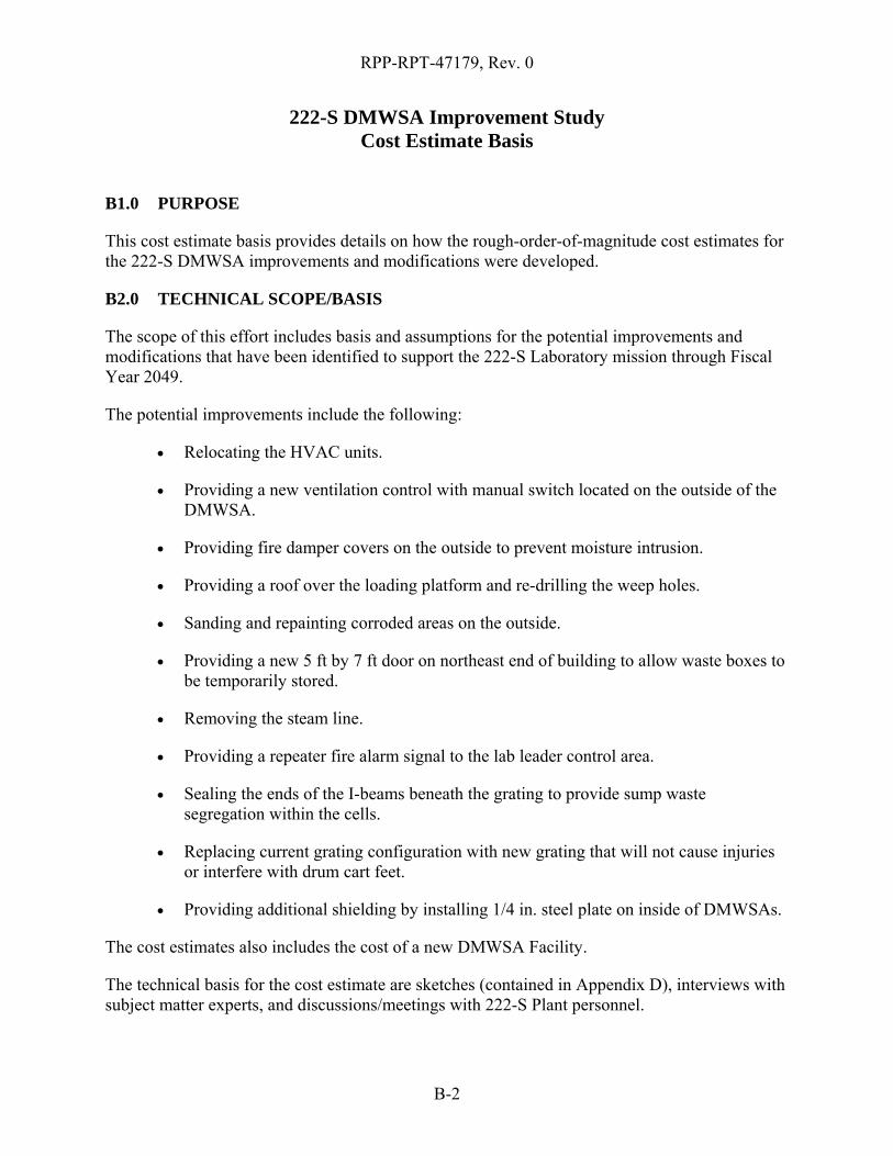
B1.0 PURPOSE
This cost estimate basis provides details on how the rough-order-of-magnitude cost estimates for the 222-S DMWSA improvements and modifications were developed.
B2.0 TECHNICAL SCOPE/BASIS
The scope of this effort includes basis and assumptions for the potential improvements and modifications that have been identified to support the 222-S Laboratory mission through Fiscal Year 2049.
The potential improvements include the following:
• Relocating the HVAC units.
• Providing a new ventilation control with manual switch located on the outside of the DMWSA.
• Providing fire damper covers on the outside to prevent moisture intrusion.
• Providing a roof over the loading platform and re-drilling the weep holes.
• Sanding and repainting corroded areas on the outside.
• Providing a new 5 ft by 7 ft door on northeast end of building to allow waste boxes to be temporarily stored.
• Removing the steam line.
• Providing a repeater fire alarm signal to the lab leader control area.
• Sealing the ends of the I-beams beneath the grating to provide sump waste segregation within the cells.
• Replacing current grating configuration with new grating that will not cause injuries or interfere with drum cart feet.
• Providing additional shielding by installing 1/4 in. steel plate on inside of DMWSAs.
The cost estimates also includes the cost of a new DMWSA Facility.
The technical basis for the cost estimate are sketches (contained in Appendix D), interviews with subject matter experts, and discussions/meetings with 222-S Plant personnel.

RPP-RPT-47179, Rev. 0
B-3
B3.0 METHODOLOGY
Estimates are generally considered “bottoms-up” estimates; utilizing quantities from sketches, information obtained from reference drawings, information acquired from narratives, input from the client, field walkdowns, and various technical assumptions. Estimating allowances were also used where the scope was inadequately defined. Material prices, labor unit hours, rental equipment usage costs, and subcontract costs were obtained from vendor budgetary quotes, RSMeans®1 2010 Cost Data (Facilities Construction database), customer provided information, and historical cost data (direct costs escalated to current year as applicable). The Estimator’s judgment was also used during the preparation of the cost estimates.
B3.1. BASE COSTS
Base costs are derived by developing costs for each estimate detail at the cost element level. These cost elements include labor, equipment usage, materials, subcontracts, and process equipment. Unit pricing is generated for each element from sources as described in the Technical Scope/Basis. Estimating judgment is applied to unit pricing based on data from published standards, vendor quotes, and other similar data, to account for site conditions and site safety requirements. Material costs are modified to account for any applicable quality assurance requirements.
B3.1.1 General Contractor Labor Costs
Construction will be performed by either a construction contractor or plant forces depending on a plant forces work review determination. For planning purposes, it is expected that the construction will be performed by a construction contractor.
Craft labor rates were derived from the Davis-Bacon Wage Rate Determinations for Hanford and are extended to workman’s compensation, FICA, state, and federal unemployment insurance and employer-specific union fees.
Non-craft labor rates utilized assume base labor wages based on typical general contracting construction companies. Base rates are extended similar to the craft labor rates in order to generate a direct rate which includes fringe benefits.
Note that overhead costs for both craft and non-craft labor are accounted for in the general contractor markups.
B3.2. MARKUPS AND OTHER DIRECT COSTS
Markups and other direct costs are incorporated to account for additional direct and indirect costs associated with performing the work. The markups and other direct costs are percentage multipliers applied to various base costs.
1 RSMeans is a registered trademark of R. S. Means Company, Inc., Kingston, Massachusetts.
RPP-RPT-47179, Rev. 0
B-4
B3.2.1 Consumables
The consumables calculation is 4% for this estimate. It is a percentage of total base labor and is based on general construction practices. This calculated amount accounts for miscellaneous materials used in the performance of construction activities, such as small tools, weld rod, tape, caulk, plastics, gloves, fasteners, construction personnel protective equipment, etc. These items are not otherwise included in the material take-off for this estimate.
B3.2.2 Cleanup
The cleanup calculation is 7% for this estimate. It is a percentage of total base labor and is based on general construction practices. This calculated amount accounts for cleanup of the construction site during and after the project is complete.
B3.2.3 Quality Assurance/Inspections
The quality assurance/inspection calculation is 3% for this estimate. It is a percentage of total base labor and is based on general construction practices. This calculated amount accounts for quality inspection and quality assurance personnel.
B3.2.4 Personnel/Material Movement
The personnel/material movement calculation is 5% for this estimate. It is a percentage of total base labor and is based on general construction practices. It accounts for the costs associated with moving craftsman and materials from the laydown yard to the job site, off loading trucks, etc.
B3.2.5 Other General Conditions
The other general conditions calculation is 5% for this estimate. It is a percentage of total base labor and is based on general construction practices. It accounts for the costs associated with security barriers, signage, temporary lighting, temporary ventilation, congested work areas, minor scaffolding, and other miscellaneous costs.
B3.2.6 General Contractor Markup
The general contractor markup is used to calculate indirect costs consisting of home office overhead, field office overhead, and profit. It is a percentage of the base cost/general requirements subtotal, less the subcontract subtotal. A 35% factor has been applied for general contractor markup, broken down as follows:

RPP-RPT-47179, Rev. 0
B-5
Home Office Overhead 6% • Payroll 1.5% • Contract Administration 1.5% • Clerical 1.0% • Bonds/Insurance 2.0%
Field Office Overhead 19% • Project Management 4.0% • Superintendent 5.0% • Field Engineer 4.0% • Material Coord/Procurement 2.0% • Warehousing 2.0% • Administration 2.0%
Profit 10% Total Markup 35%
B3.2.7 Subcontractor Markup
The cost estimate accounts for a 20% markup of all subcontract costs. This accounts for all indirect costs the general contractor incurs when managing subcontractors, which equates to 10%. The other 10% is for subcontractor field administration and overhead and profit. This markup is historically a typical percentage found in contracts of this nature and is applied only to subcontract base (direct) costs.
B3.2.8 Sales Tax
Washington State sales tax of 8.3% is based on the current established tax rate. The sales tax is applied to equipment usage, materials, process equipment, and consumables.
B3.2.9 Engineering (Conceptual, Preliminary, Detailed, Engineering During Construction)
The expected engineering costs for conceptual, preliminary and detailed design activities have been calculated based on total construction costs (direct costs plus general requirements plus contractor markups plus sales tax).
The engineering during construction includes costs for general engineering support, Engineering Change Notice preparation, submittal review, Review Comment Record disposition, as-builting, etc. It has been assumed that engineering costs during construction will be based on the total construction costs (direct costs plus general requirements plus contractor markups plus sales tax).
B3.2.10 WRPS Markups
WRPS support functions have been factored into the estimate to ensure total project costs are captured. Support functions have been factored by use of a percentage. The WRPS support activities and what they encompass are as follows:
• Project Management – includes project managers, project controls, scheduling, administration, etc.

RPP-RPT-47179, Rev. 0
B-6
• Project Support – includes discipline engineering to: 1) develop, review, and approval of design media; 2) prepare/issue work plans; 3) develop safety documentation; 4) provide engineering support during construction; and 5) provide other support as required.
• Procurement Support – includes activities such as preparing statements of work, awarding contracts, preparing quality assurance inspection plans, performing other quality assurance activities, and managing procurements as required.
• Construction Management – this includes a construction manager, construction field engineers, clerical/document control, and contract administration.
• Construction Support – this includes a variety of activities, such as: 1) Health Physics Technician support; 2) Industrial Health support; 3) WRPS crane usage, 4) planning and work package preparation; 5) Unreviewed safety question preparation; 6) Engineering Change Notice support; 7) Pre/Post Job Briefings; 8) Radiation Work Permit preparation; and, 9) lock/tag outs, leak check, etc.
• Startup Support – this includes startup activities in support of the project.
• Operations Support – this includes any other operational support required of the project. Operations Support costs are not included in this estimate.
B3.3. ESCALATION
Escalation has not been applied to this estimate since it is not known yet when these upgrades will occur. All costs are in FY 2010 dollars.
B3.4. CONTINGENCY
As assessment of work complexity, project uncertainty, and scope definition was performed. This is a project cost estimate based on a pre-conceptual design (study level). In most cases, scope has been minimally defined. Therefore, the contingency used in the estimates are typical for an estimate based on minimal, if any, design information. The percentage applied is 35%.
B4.0 ASSUMPTIONS
During the preparation of this estimate, assumptions were made that affect the cost estimate. These assumptions are a primary and integral element of the cost estimate basis, and are essential to understanding the organization, scope, and costs associated with this cost estimate. If any of the estimating assumptions ultimately proves to be invalid, the cost estimate should be re-evaluated for cost impacts.
RPP-RPT-47179, Rev. 0
B-7
B4.1. GENERAL ASSUMPTIONS
• Escalation is not applicable.
• Conceptual design activities are not required for any of the upgrades.
• Construction Forces will complete all non-specialized work.
• Construction will be accomplished through normal 8-hour shifts to accommodate on-going operations.
• Training consists of 4 manhours for badging, 4 manhours for HGET, 4 manhours for building orientation, and 40 manhours for Hazardous Material Training, if required.
• The exact locations and elevations for underground utilities were not available.
• No asbestos material removal will be required.
• No lead-based paint will be encountered during demolition.
• All generated waste will be considered low-level waste and disposed of at Environmental Restoration Disposal Facility.
B4.2. RELOCATE HVAC UNITS
• Replacement HVAC units will be a replacement in kind.
• The new HVAC unit will be supported by an existing concrete pad.
B4.3. UPGRADE HVAC CONTROL SYSTEM
• New control system will be mounted outside of the DMWSA.
• Demolition is not required.
B4.4. INSTALL FIRE DAMPER COVER
• Eight covers will be installed.
B4.5. CORROSION CONTROL
• Only visible corrosion areas will be fixed. The underside of the DMWSA will not be painted.
B4.6. DOOR OPENING
• Only one access door will be provided on DMWSA HS-0083.
RPP-RPT-47179, Rev. 0
B-8
B4.7. ACCESSIBILITY
• Removal of the steam line and poles will be performed by Steam to Electric Project. No estimate was developed for this study.
B4.8. FIRE PROTECTION
• Alarm signal is only needed in the lab leader control area and will not be connected to the 222-S main fire control system.
• Work will be subcontracted to fire control specialists.
B4.9. IMPROVE LOADING PLATFORM
B4.10. WASTE SEGREGATION
B4.11. SUMP DUMP GRATES
B4.12. SHIELDING
• Shielding will only be for the North, East, and West outer walls.
• Shielding material will require its own support system, and will be applied on the external walls.
B4.13. NEW FACILITY
• New facility will be a pre-engineered metal building with concrete blocks on the inside to be used as shielding.
• An overhead crane will be installed within the new facility (7.5 ton bridge crane).
RPP-RPT-47179, Rev. 0
C-1
APPENDIX C
RISK ANALYSIS
Table of Contents C1.0 PURPOSE AND SCOPE .................................................................................................C-2
C2.0 BACKGROUND .............................................................................................................C-2
C3.0 RISK ANALYSIS PROCESS .........................................................................................C-2 C3.1. GENERAL RISK CATEGORIES .......................................................................C-4 C3.2. LIKELIHOOD CATEGORIES ...........................................................................C-4
C4.0 RISK ANALYSIS RESULTS .........................................................................................C-5
C5.0 REFERENCES ................................................................................................................C-7 ATTACHMENTS Attachment A
Risk Analysis Matrix Table
Attachment B Template for Risk Analysis Evaluation Sheet
Attachment C Risk Evaluation Sheets
Attachment D List of Participants in Risk Evaluation Meetings
Tables Table C-2. Likelihood Levels. ................................................................................................... C-5
Table C-3. Upgrade Risk Reduction Summary. ........................................................................ C-6
Table C-4. New Facility Risk Reduction Summary. ................................................................. C-7
RPP-RPT-47179, Rev. 0
C-2
C1.0 PURPOSE AND SCOPE
This analysis describes the risk-based priority evaluation of DMWSA Facility improvements documented in the 222-S DMWSA Improvement Study. The purpose of the analysis was to prioritize each upgrade relative to other potential upgrades as well as evaluate a new facility by evaluating risk reduction of a new facility compared to an upgraded existing facility (i.e., assuming all upgrades described in the 222-S DMWSA Improvement Study are successfully completed).
The scope of the evaluation was the selected equipment and facility upgrades identified by 222-S Laboratory personnel and documented in the 222-S DMWSA Improvement Study. If new ideas for equipment or facility upgrades were generated during discussions with 222-S Laboratory personnel, they were added to the study with consensus and evaluated accordingly.
C2.0 BACKGROUND
This appendix supports the 222-S DMWSA Improvement Study, which identifies the facility and equipment upgrades necessary for safe and efficient operation of the 222-S DMWSA Facility. Upgrade planning is based on current requirements from the DOE orders, Washington State regulations, applicable industry codes and standards, and the results from numerous external audits and internal self-assessments. A risk-based prioritization of the upgrades was required to evaluate the relative merit of the proposed upgrades contained in the study.
It has been observed that life extension upgrades can be a challenge to properly rank, because of the inherent difficulty in comparing upgrades with diverse purpose, cost, and functionality. However, with incomplete information inherent in the process, risk guidelines used that elicit expert opinion to overcome this lack of information and to assess proposed upgrades in a uniform and consistent manner.
C3.0 RISK ANALYSIS PROCESS
The analysis process is based on the DOE Risk-Based Prioritization Model [Reference 1] and was adjusted to suit the evaluation requirements of the 222-S DMWSA improvements.
The Risk-Based Prioritization Model was developed by DOE as a consistent method of evaluating risks associated with its programs. DOE applied the Risk-Based Prioritization Model to rank many of its projects for the DOE Management Planning Process. Because of its flexibility, the model has been used to rank many different types of work, including occupational safety improvements, capital upgrade projects, infrastructure maintenance, improvements in conduct of operations, and others. Facilities having applied the process range from small solar energy laboratories and fossil energy facilities to large nuclear weapons facilities.
For this analysis, “risk” was defined as the product of consequence of an event to occur and likelihood of the occurrence of the event. Other definitions of “risk” were excluded as not applicable to this analysis. The process was designed to determine the relative effectiveness of the improvement to reduce risk, not to determine the magnitude of current problems or issues that the upgrades are intended to address.

RPP-RPT-47179, Rev. 0
C-3
The 222-S DMWSA Facility improvements were evaluated and ranked to support the Laboratory’s management and decision-making process. Group meetings were held with subject matter experts and Laboratory management in a round table fashion. Each improvement was discussed at length to determine risk scores. An example of a Risk Analysis Evaluation Sheet is shown as Attachment B. The list of 222-S DMWSA Improvement Study meeting participants is shown in Attachment D.
Improvements were ranked based on their expected ability to reduce the Laboratory’s risk in all nine of the general risk categories shown in Table C-1 [References 1 and 2]. With Regard to potential upgrades, risk was evaluated with the current situation to determine a “Before” upgrade-implementation score. Then, a similar evaluation was conducted to determine the future situation for an “After” upgrade-implementation score. In the new facility improvement case, the “Before” score represented an upgraded existing facility (i.e., assuming that all upgrades described in Section 4.0 are successfully completed) then an “After” score reflected a new facility. This comparison of a new facility to an upgraded existing facility supported identification of long term risk reduction and flexibility associated with a new facility, even if the potential near term upgrades (essentially maintenance activities) are completed. The factors discussed were conditions and consequences that might occur, if the improvements were not implemented and the likelihood of experiencing those consequences; against the “After” improvement conditions. The Risk Reduction score was calculated by taking the difference between the “Before” and “After” risk score.
General risk categories applied on other DOE projects [References 2 and 3] guided the evaluation of equipment and facility improvements for the 222-S DMWSA Facility. Each category was assessed for both consequences and likelihoods of occurrence for a risk score. The Risk Analysis Matrix Table is shown in Attachment A. The rows of the matrix define consequence levels in each risk category. The columns define likelihood levels. Each cell (row and column combination) defines a specific risk score. The cell values represent a numeric weight corresponding to a unique combination of consequence and likelihood.
In almost all cases, 222-S Laboratory personnel determined these cell values to be adequate to support prioritization of upgrades. In a very small number of cases, the values were adjusted after discussion among the subject matter experts and facility personnel. The adjusted values were retained and recorded in the evaluation sheet detailing the selected upgrade. The accepted adjustment was to select a discrete value that received group concurrence and retained the designations for impact weight (row) and likelihood (column).
For example, under E.0, Facility Impact, if a consequence was assessed as having a “high” likelihood of occurrence with Disruption of Operation of 90 days, then the event did not fit in either E.3, “Disruption of Operation – 1-week,” or E.4, “Disruption of Operation – 6-months.” The risk values were adjusted between E.3 with risk value of 275, and E.4 with risk value of 500. In this case, after group discussion, a value of 400 was chosen to represent a 90-day timeframe between 1 week and 6 months.
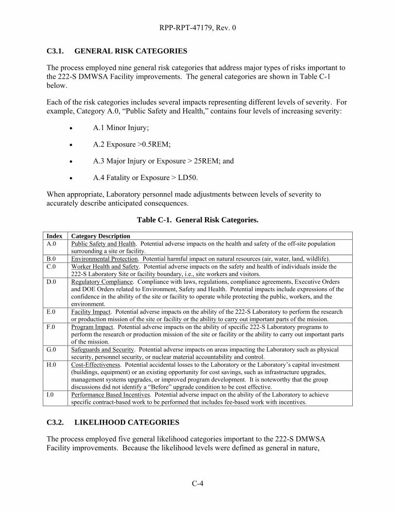
RPP-RPT-47179, Rev. 0
C-4
C3.1. GENERAL RISK CATEGORIES
The process employed nine general risk categories that address major types of risks important to the 222-S DMWSA Facility improvements. The general categories are shown in Table C-1 below.
Each of the risk categories includes several impacts representing different levels of severity. For example, Category A.0, “Public Safety and Health,” contains four levels of increasing severity:
• A.1 Minor Injury;
• A.2 Exposure >0.5REM;
• A.3 Major Injury or Exposure > 25REM; and
• A.4 Fatality or Exposure > LD50.
When appropriate, Laboratory personnel made adjustments between levels of severity to accurately describe anticipated consequences.
Table C-1. General Risk Categories.
Index Category Description A.0 Public Safety and Health. Potential adverse impacts on the health and safety of the off-site population
surrounding a site or facility. B.0 Environmental Protection. Potential harmful impact on natural resources (air, water, land, wildlife). C.0 Worker Health and Safety. Potential adverse impacts on the safety and health of individuals inside the
222-S Laboratory Site or facility boundary, i.e., site workers and visitors. D.0 Regulatory Compliance. Compliance with laws, regulations, compliance agreements, Executive Orders
and DOE Orders related to Environment, Safety and Health. Potential impacts include expressions of the confidence in the ability of the site or facility to operate while protecting the public, workers, and the environment.
E.0 Facility Impact. Potential adverse impacts on the ability of the 222-S Laboratory to perform the research or production mission of the site or facility or the ability to carry out important parts of the mission.
F.0 Program Impact. Potential adverse impacts on the ability of specific 222-S Laboratory programs to perform the research or production mission of the site or facility or the ability to carry out important parts of the mission.
G.0 Safeguards and Security. Potential adverse impacts on areas impacting the Laboratory such as physical security, personnel security, or nuclear material accountability and control.
H.0 Cost-Effectiveness. Potential accidental losses to the Laboratory or the Laboratory’s capital investment (buildings, equipment) or an existing opportunity for cost savings, such as infrastructure upgrades, management systems upgrades, or improved program development. It is noteworthy that the group discussions did not identify a “Before” upgrade condition to be cost effective.
I.0 Performance Based Incentives. Potential adverse impact on the ability of the Laboratory to achieve specific contract-based work to be performed that includes fee-based work with incentives.
C3.2. LIKELIHOOD CATEGORIES
The process employed five general likelihood categories important to the 222-S DMWSA Facility improvements. Because the likelihood levels were defined as general in nature,
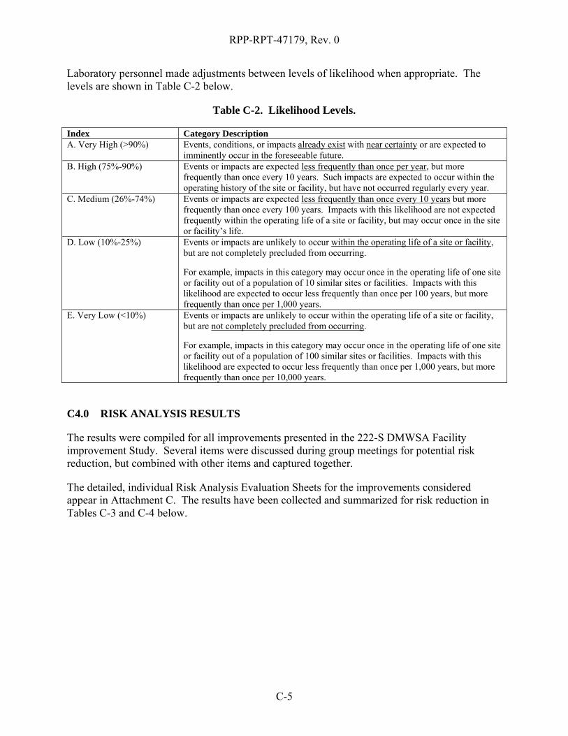
RPP-RPT-47179, Rev. 0
C-5
Laboratory personnel made adjustments between levels of likelihood when appropriate. The levels are shown in Table C-2 below.
Table C-2. Likelihood Levels.
Index Category Description A. Very High (>90%)
Events, conditions, or impacts already exist with near certainty or are expected to imminently occur in the foreseeable future.
B. High (75%-90%)
Events or impacts are expected less frequently than once per year, but more frequently than once every 10 years. Such impacts are expected to occur within the operating history of the site or facility, but have not occurred regularly every year.
C. Medium (26%-74%)
Events or impacts are expected less frequently than once every 10 years but more frequently than once every 100 years. Impacts with this likelihood are not expected frequently within the operating life of a site or facility, but may occur once in the site or facility’s life.
D. Low (10%-25%)
Events or impacts are unlikely to occur within the operating life of a site or facility, but are not completely precluded from occurring. For example, impacts in this category may occur once in the operating life of one site or facility out of a population of 10 similar sites or facilities. Impacts with this likelihood are expected to occur less frequently than once per 100 years, but more frequently than once per 1,000 years.
E. Very Low (<10%)
Events or impacts are unlikely to occur within the operating life of a site or facility, but are not completely precluded from occurring. For example, impacts in this category may occur once in the operating life of one site or facility out of a population of 100 similar sites or facilities. Impacts with this likelihood are expected to occur less frequently than once per 1,000 years, but more frequently than once per 10,000 years.
C4.0 RISK ANALYSIS RESULTS
The results were compiled for all improvements presented in the 222-S DMWSA Facility improvement Study. Several items were discussed during group meetings for potential risk reduction, but combined with other items and captured together.
The detailed, individual Risk Analysis Evaluation Sheets for the improvements considered appear in Attachment C. The results have been collected and summarized for risk reduction in Tables C-3 and C-4 below.
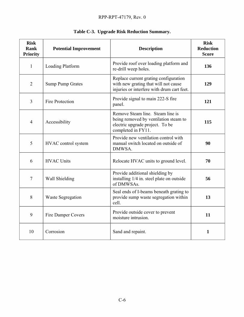
RPP-RPT-47179, Rev. 0
C-6
Table C-3. Upgrade Risk Reduction Summary.
Risk Rank
Priority Potential Improvement Description
Risk Reduction
Score
1 Loading Platform Provide roof over loading platform and re-drill weep holes. 136
2 Sump Pump Grates Replace current grating configuration with new grating that will not cause injuries or interfere with drum cart feet.
129
3 Fire Protection Provide signal to main 222-S fire panel. 121
4 Accessibility
Remove Steam line. Steam line is being removed by ventilation steam to electric upgrade project. To be completed in FY11.
115
5 HVAC control system Provide new ventilation control with manual switch located on outside of DMWSA.
90
6 HVAC Units Relocate HVAC units to ground level. 70
7 Wall Shielding Provide additional shielding by installing 1/4 in. steel plate on outside of DMWSAs.
56
8 Waste Segregation Seal ends of I-beams beneath grating to provide sump waste segregation within cell.
13
9 Fire Damper Covers Provide outside cover to prevent moisture intrusion. 11
10 Corrosion Sand and repaint. 1

RPP-RPT-47179, Rev. 0
C-7
Table C-4. New Facility Risk Reduction Summary.
Risk Rank Priority
Potential Improvement Description
Risk Reduction
Score
Not Applicable New Facility Consolidate DMWSA activities to a single building outside door 16. 321
C5.0 REFERENCES
[1] PMG-30, 1996, “Project Management Prioritization Guide,” U.S. Department of Energy, Office of Field Management, Washington, D.C.
[2] “Risk Prioritization Manual,” Office of Assurance, Stanford Linear Accelerator Center,
I-770-0A19Z-002-R000, US Department of Energy, DE-AC02-76-SFO0515, 3 Aug 2007.
[3] “Preparation and review of ES&H and Infrastructure Management Plan,” J. L. Monhart,
DOE Fermi Laboratory, FAO 2.5, 15 Aug 2001.

RPP-RPT-47179, Rev. 0
C-8
Attachment A
Risk Analysis Matrix Table
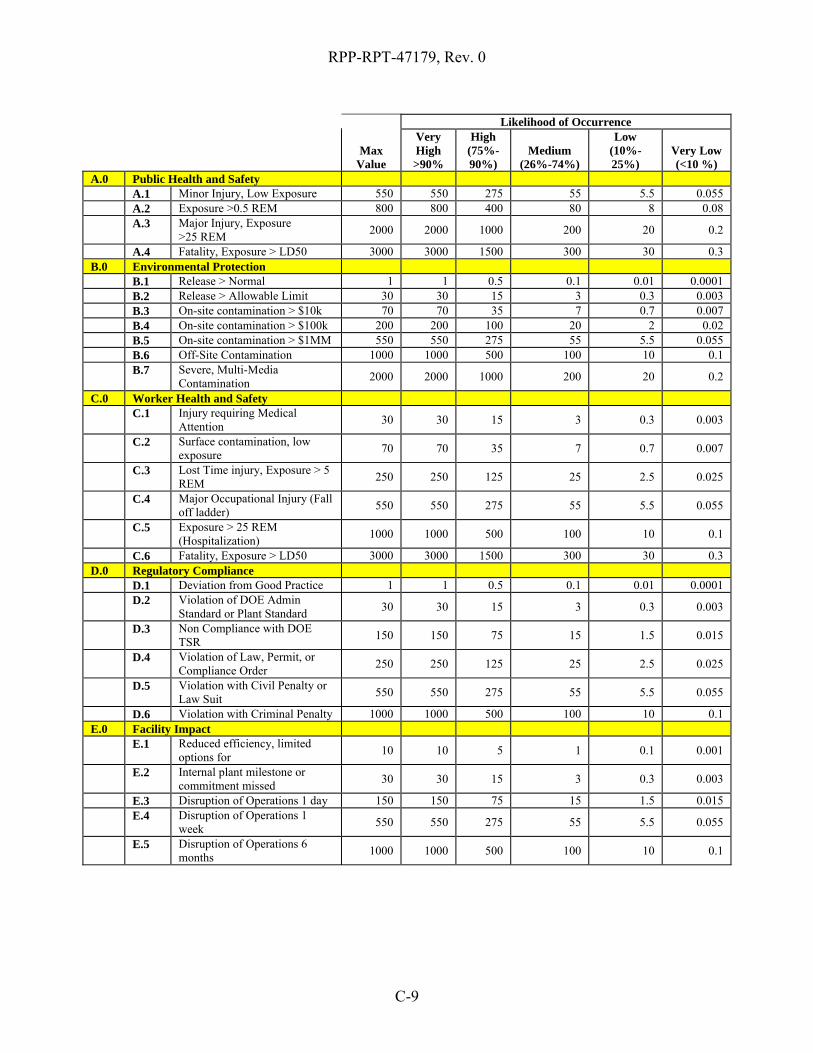
RPP-RPT-47179, Rev. 0
C-9
Max Value
Likelihood of Occurrence Very
High >90%
High (75%- 90%)
Medium (26%-74%)
Low (10%-25%)
Very Low(<10 %)
A.0 Public Health and Safety A.1 Minor Injury, Low Exposure 550 550 275 55 5.5 0.055 A.2 Exposure >0.5 REM 800 800 400 80 8 0.08
A.3 Major Injury, Exposure
>25 REM 2000 2000 1000 200 20 0.2
A.4 Fatality, Exposure > LD50 3000 3000 1500 300 30 0.3 B.0 Environmental Protection B.1 Release > Normal 1 1 0.5 0.1 0.01 0.0001 B.2 Release > Allowable Limit 30 30 15 3 0.3 0.003 B.3 On-site contamination > $10k 70 70 35 7 0.7 0.007 B.4 On-site contamination > $100k 200 200 100 20 2 0.02 B.5 On-site contamination > $1MM 550 550 275 55 5.5 0.055 B.6 Off-Site Contamination 1000 1000 500 100 10 0.1
B.7 Severe, Multi-Media
Contamination 2000 2000 1000 200 20 0.2
C.0 Worker Health and Safety
C.1 Injury requiring Medical
Attention 30 30 15 3 0.3 0.003
C.2 Surface contamination, low
exposure 70 70 35 7 0.7 0.007
C.3 Lost Time injury, Exposure > 5
REM 250 250 125 25 2.5 0.025
C.4 Major Occupational Injury (Fall
off ladder) 550 550 275 55 5.5 0.055
C.5 Exposure > 25 REM
(Hospitalization) 1000 1000 500 100 10 0.1
C.6 Fatality, Exposure > LD50 3000 3000 1500 300 30 0.3 D.0 Regulatory Compliance D.1 Deviation from Good Practice 1 1 0.5 0.1 0.01 0.0001
D.2 Violation of DOE Admin
Standard or Plant Standard 30 30 15 3 0.3 0.003
D.3 Non Compliance with DOE
TSR 150 150 75 15 1.5 0.015
D.4 Violation of Law, Permit, or
Compliance Order 250 250 125 25 2.5 0.025
D.5 Violation with Civil Penalty or
Law Suit 550 550 275 55 5.5 0.055
D.6 Violation with Criminal Penalty 1000 1000 500 100 10 0.1 E.0 Facility Impact
E.1 Reduced efficiency, limited
options for 10 10 5 1 0.1 0.001
E.2 Internal plant milestone or
commitment missed 30 30 15 3 0.3 0.003
E.3 Disruption of Operations 1 day 150 150 75 15 1.5 0.015
E.4 Disruption of Operations 1
week 550 550 275 55 5.5 0.055
E.5 Disruption of Operations 6
months 1000 1000 500 100 10 0.1

RPP-RPT-47179, Rev. 0
C-10
Max Value
Likelihood of Occurrence Very
High >90%
High (75%- 90%)
Medium (26%-74%)
Low (10%-25%)
Very Low(<10 %)
F.0 Program Impact
F.1 Productivity improvements not
achieved 10 10 5 1 0.1 0.001
F.2 Single point equipment failure 30 30 15 3 0.3 0.003
F.3 Gateway to Outyear Program
Milestone (TPA) 130 130 65 13 1.3 0.013
F.4 Time critical action to achieve
current Fiscal Year Milestone 750 750 375 75 7.5 0.075
G.0 Safeguards and Security
G.1 Theft of Government Property -
Non SNM, non-Classified 1 1 0.5 0.1 0.01 0.0001
G.2 Sabotage of a non-nuclear
process 30 30 15 3 0.3 0.003
G.3 Theft of classified material 70 70 35 7 0.7 0.007
G.4 SNM inventory imbalance; loss
of accountability 300 300 150 30 3 0.03
G.5 Sabotage of a nuclear process 550 550 275 55 5.5 0.055 G.6 Outsider penetration of MAA 1500 1500 750 150 15 0.15 G.7 Loss of weapon-grade SNM 3000 3000 1500 300 30 0.3 H.0 Cost Effectiveness
H.1 Minor savings / cost avoidance
< $100k; Payback > 5 years -10 -10 -5 -1 -0.1 -0.001
H.2 Moderate savings $100k-200k;
Payback 3-5 years -70 -70 -35 -7 -0.7 -0.007
H.3 High savings >$500k;
Payback 1-3 years -230 -230 -115 -23 -2.3 -0.023
H.4 Major savings > $500k;
Payback < 1 year -500 -500 -250 -50 -5 -0.05
I.0 Performance Based Incentives I.1 Missed PBI; <$250k 50 50 25 5 0.5 0.005 I.2 Missed PBI; >$250k and <$1M 150 150 75 15 1.5 0.015 I.3 Missed PBI; >$1M and <$2M 300 300 150 30 3 0.03 I.4 Missed PBI; >$2M 500 500 250 50 5 0.05

RPP-RPT-47179, Rev. 0
C-11
Attachment B
Template for Risk Analysis Evaluation Sheet

RPP-R
PT-47179, Rev. 0
C-12
123456
7891011121314151617
A B C D E F G H I J K LEvaluatorItem Number Upgrade ListEquipment/SystemDescription of Risk EventDescription of Upgrade
Before Upgrade After Upgrade
ImpactLikelihood(VH, M, L) Score Impact
Likelihood(VH, M, L) Score
Risk Reduction Score
A.0 Public Health and Safety n/a 0 n/a 0 0.0B.0 Environmental Protection n/a 0 n/a 0 0.0C.0 Worker Health and Safety n/a 0 n/a 0 0.0D.0 Regulatory Compliance n/a 0 n/a 0 0.0E.0 Facility Impact n/a 0 n/a 0 0.0F.0 Program Impact n/a 0 n/a 0 0.0G.0 Safeguards and Security n/a 0 n/a 0 0.0H.0 Cost Effectiveness n/a 0 n/a 0 0.0I.0 Performance Based Incentives n/a 0 n/a 0 0.0
Final Net Score 0.0

RPP-RPT-47179, Rev. 0
C-13
Attachment C
Risk Evaluation Sheets

C-14
RPP-R
PT-47179, Rev. 0
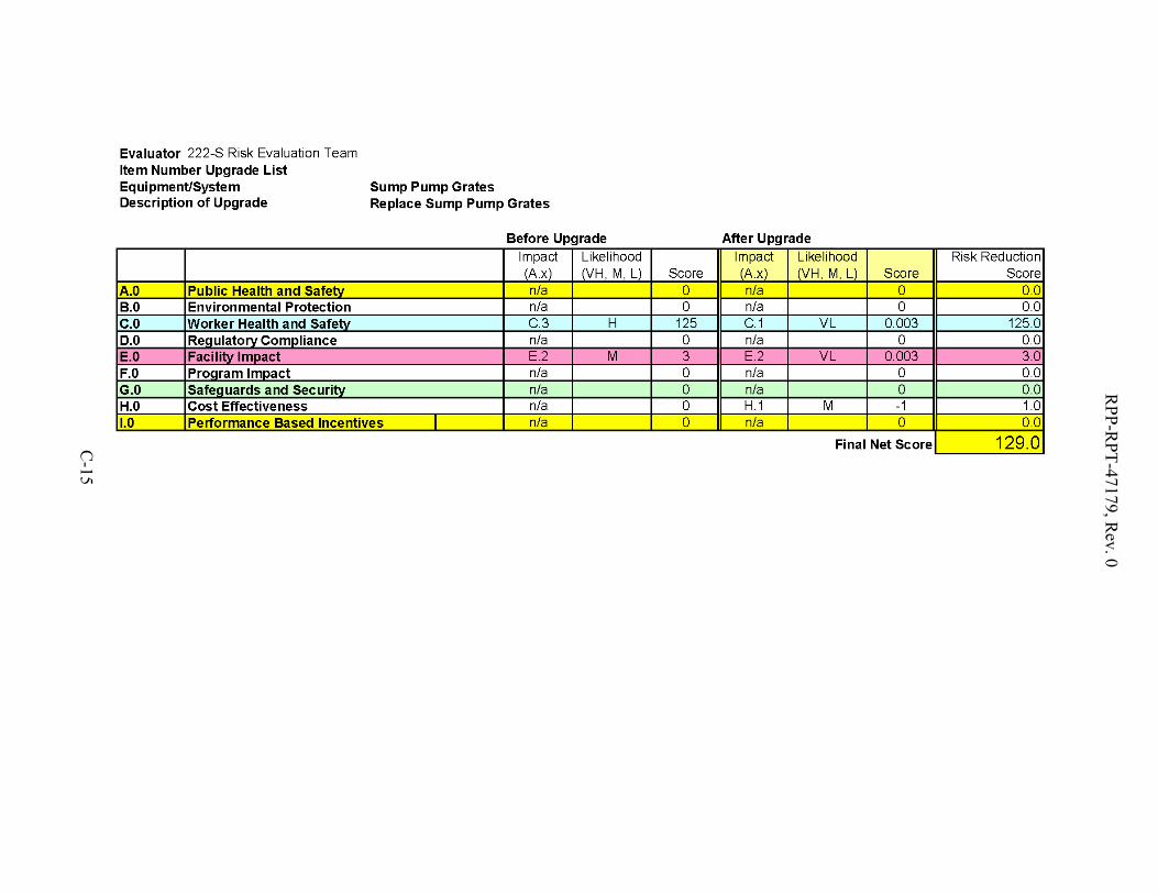
C-15
RPP-R
PT-47179, Rev. 0
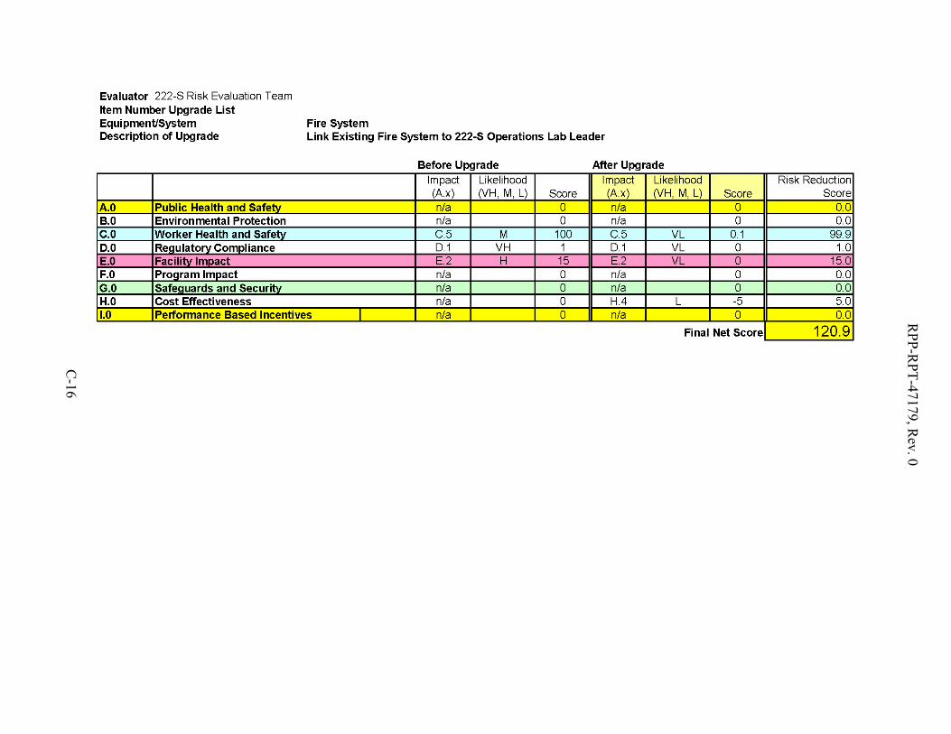
C-16
RPP-R
PT-47179, Rev. 0
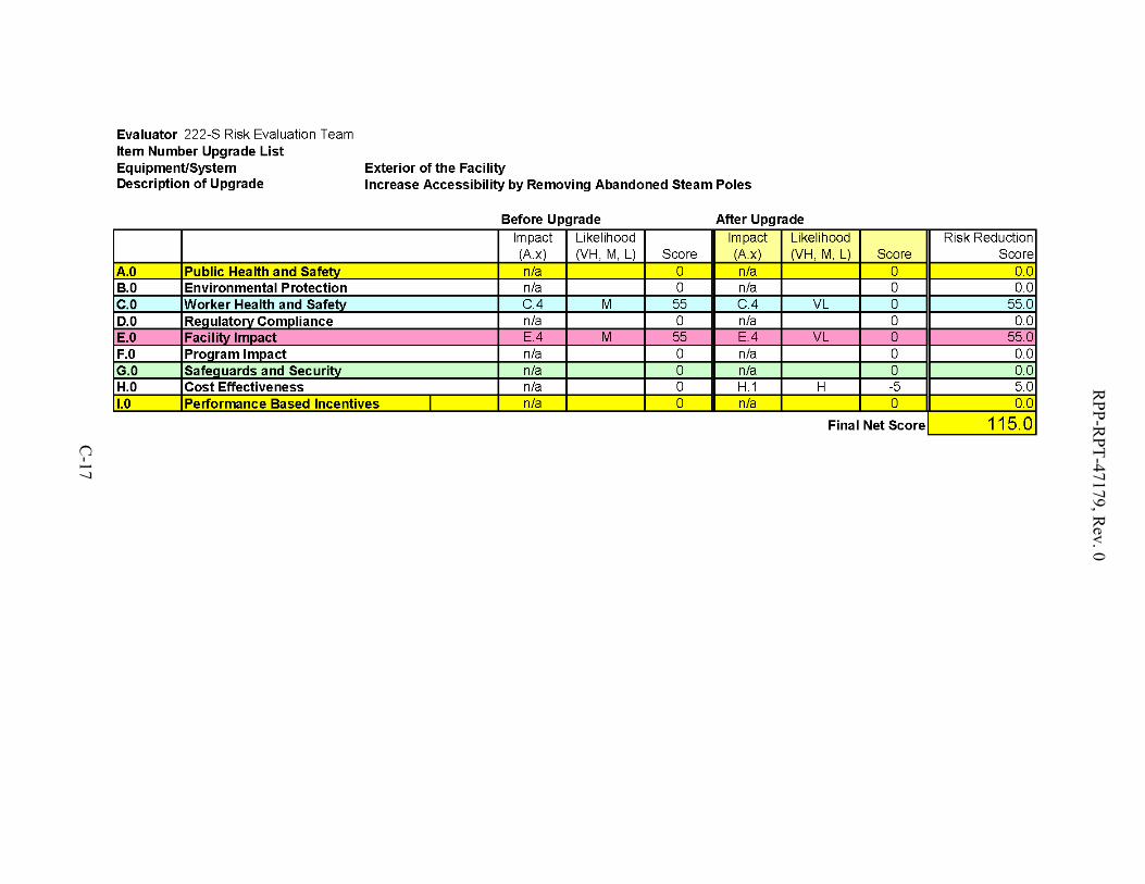
C-17
RPP-R
PT-47179, Rev. 0

C-18
RPP-R
PT-47179, Rev. 0

C-19
RPP-R
PT-47179, Rev. 0
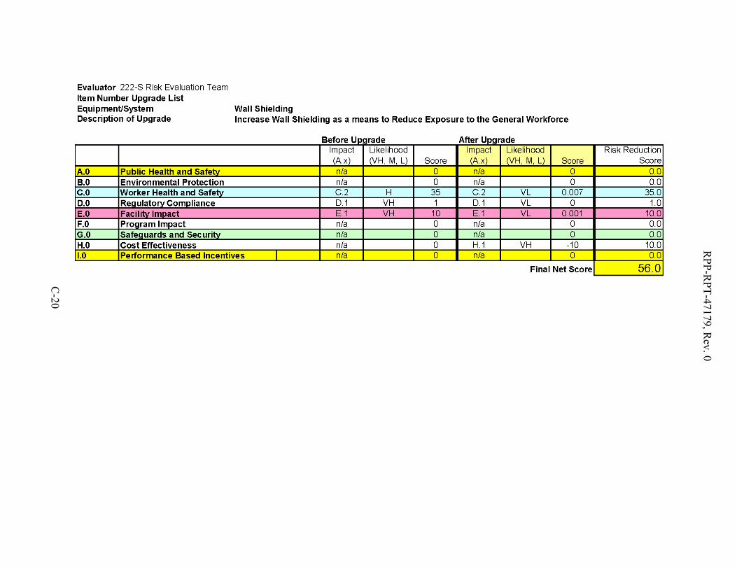
C-20
RPP-R
PT-47179, Rev. 0
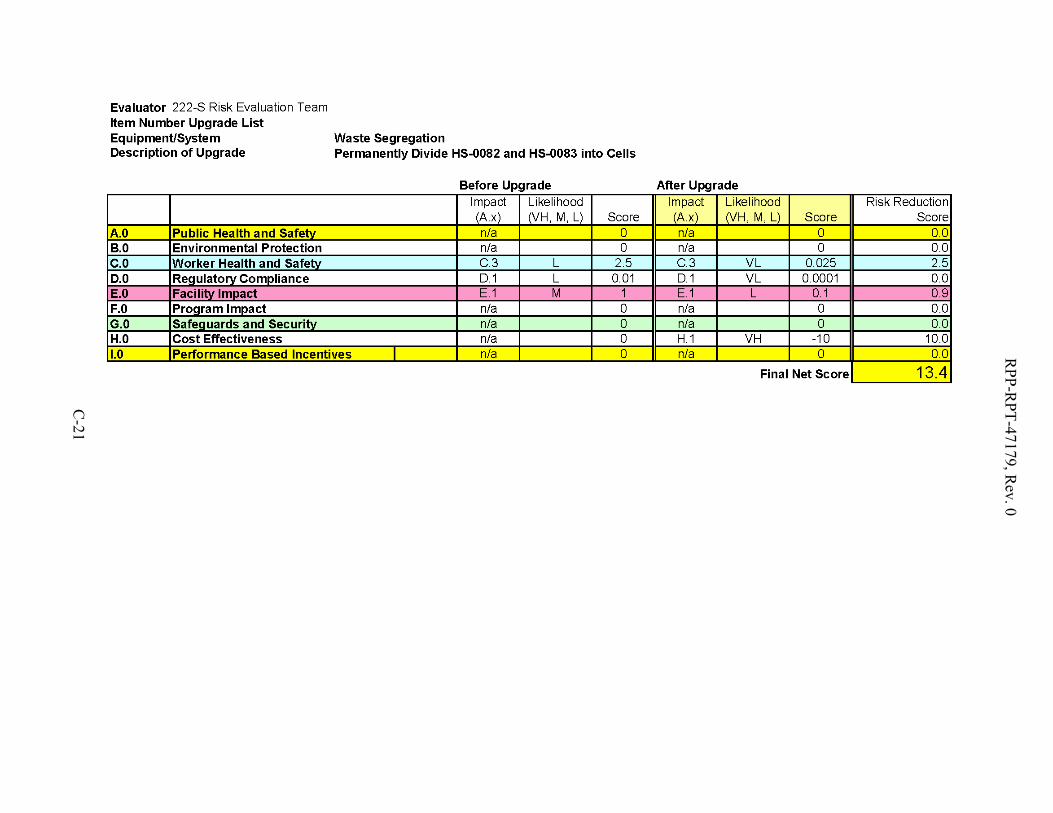
C-21
RPP-R
PT-47179, Rev. 0
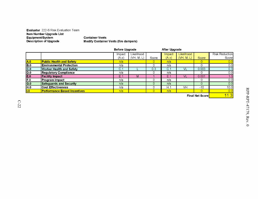
C-22
RPP-R
PT-47179, Rev. 0

C-23
RPP-R
PT-47179, Rev. 0

C-24
RPP-R
PT-47179, Rev. 0

RPP-RPT-47179, Rev. 0
C-25
Attachment D
List of Participants in Risk Evaluation Meetings

RPP-RPT-47179, Rev. 0
C-26
Name Organization Greg Parsons Project Management Dan Lucas Project Management Gary Hammitt Waste Operations Brian Simmons Waste Operations Heather Baune 219-S Facility Management Eric Tress Project Engineering Hiram Mendoza Waste Operations Larry McDaniel ARES Corporation Nathan Roe ARES Corporation Daniel Kovis ARES Corporation

RPP-RPT-47179, Rev. 0
D-1
APPENDIX D
222-S DMWSA IMPROVEMENT SKETCHES
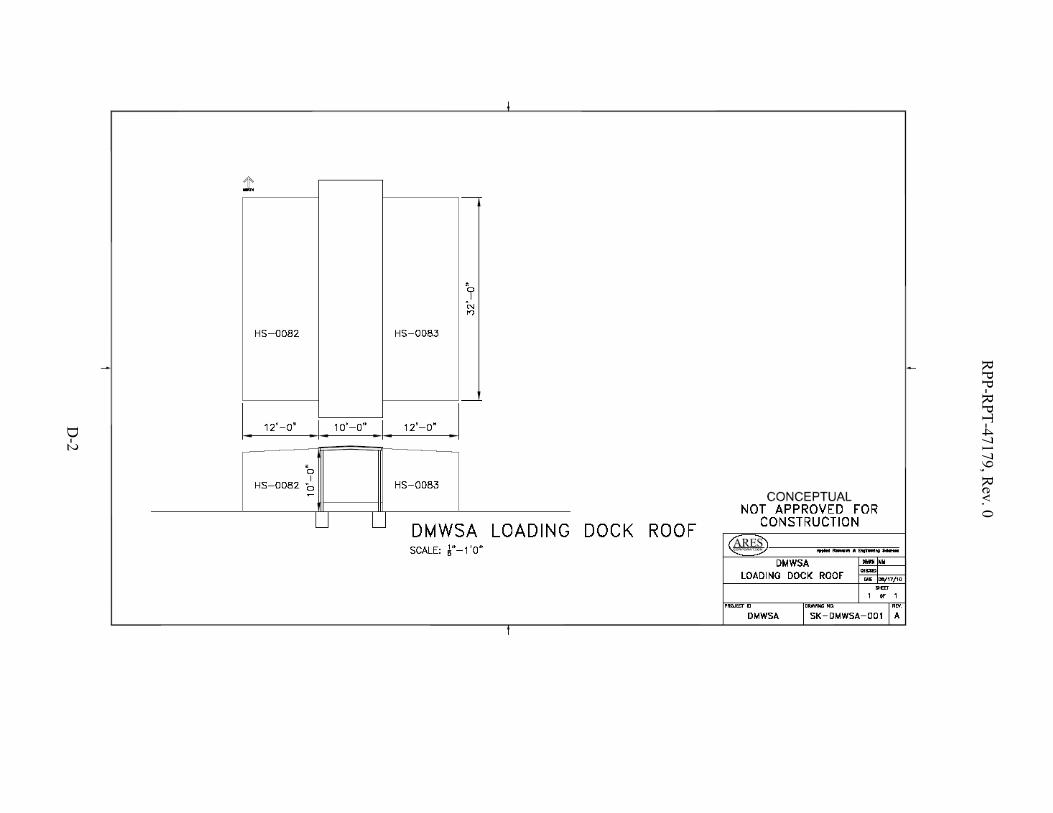
RPP-R
PT-47179, Rev. 0
D-2
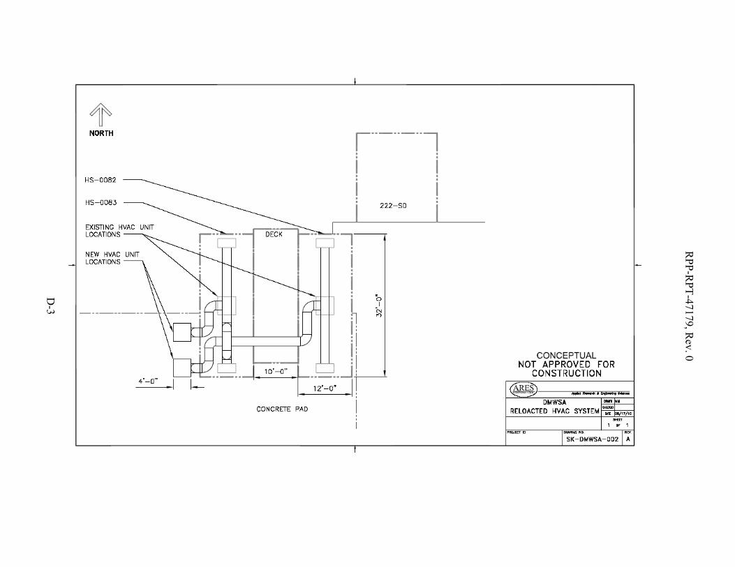
RPP-R
PT-47179, Rev. 0
D-3
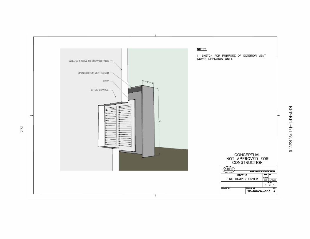
RPP-R
PT-47179, Rev. 0
D-4
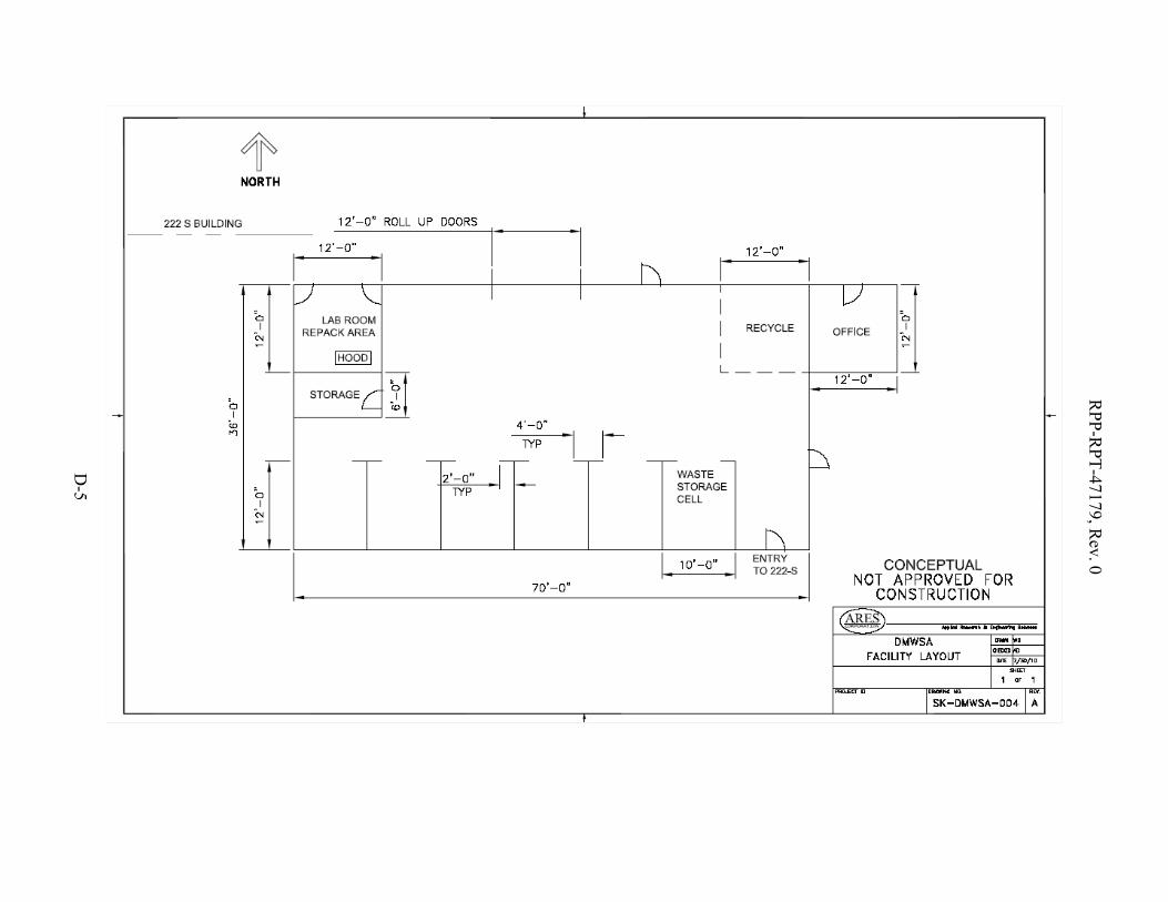
RPP-R
PT-47179, Rev. 0
D-5

RPP-R
PT-47179, Rev. 0
D-6

RPP-RPT-47179, Rev. 0
E-1
APPENDIX E
SCHEDULE
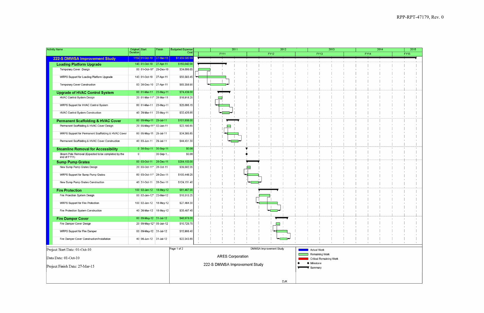
RPP-RPT-47179, Rev. 0
E-2

RPP-RPT-47179, Rev. 0
E-3