2/23/2010 r. m unden - f airfield u niversity 1 ee 350 / ece 490 a nalog c ommunication s ystems
TRANSCRIPT
2/23/2010R. MUNDEN - FAIRFIELD UNIVERSITY 1
Ch. 14 – Antennas
EE 350 / ECE 490ANALOG COMMUNICATION SYSTEMS
OBJECTIVES
Describe the development of the half-wave dipole antenna from transmission line theory
Define the properties of antenna reciprocity and polarization
Explain the antenna radiation and induction field, radiation pattern, gain, and radiation resistance
Calculate and define antenna efficiency
Describe the physical and electrical characteristics of common antenna types and arrays
Explain the ability to “electromagnetically steer” the radiation pattern of phased arrays
Differentiate between antenna beamwidth and bandwidth
Design a log-periodic antenna given the range of frequencies it is to be operated over and its design ratio
14-1 BASIC ANTENNA THEORY
Currents in an antenna produce EM waves that radiate into the atmosphere
EM waves induce AC currents in antennas for receivers to use
Antennas can transmit or receive
Antenna should be polarized the same as the EM wave
Signals strength is like field, 10 uV on a 2m antenna = 5 uV/m field strength
14-2 HALF-WAVE DIPOLE ANTENNA
Development of the Half-Wave Dipole Antenna
Half-Wave Dipole Antenna Impedance
Radiation and Induction Field
Radiation Pattern
Antenna Gain
HALF-WAVE DIPOLE ANTENNA
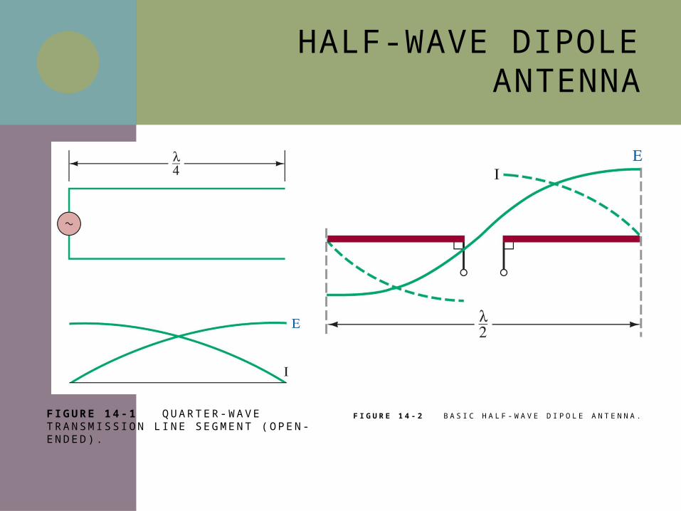
F IGURE 14 -1 Q U A RT E R-WAV E T RA N S M I S S I O N L I N E S E G M E N T ( O P E N - E N D E D ) .
F I G U R E 1 4 - 2 B A S I C H A L F - W A V E D I P O L E A N T E N N A .
HALF-WAVE DIPOLE IMPEDANCE
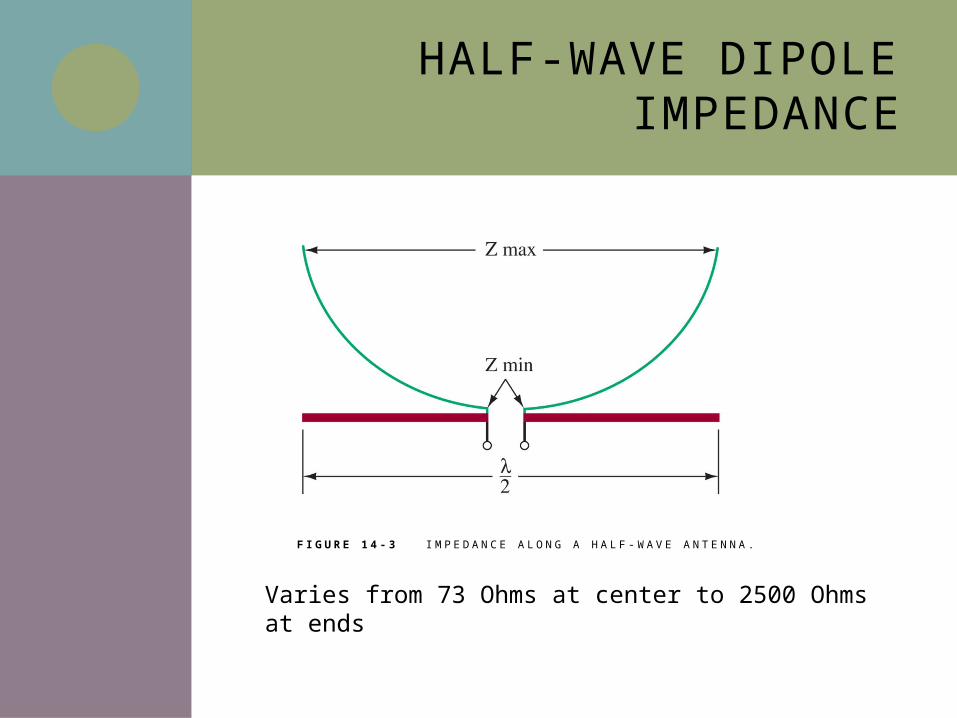
F I G U R E 1 4 - 3 I M P E D A N C E A L O N G A H A L F - W A V E A N T E N N A .
Varies from 73 Ohms at center to 2500 Ohms at ends
RADIATION AND INDUCTION FIELDS
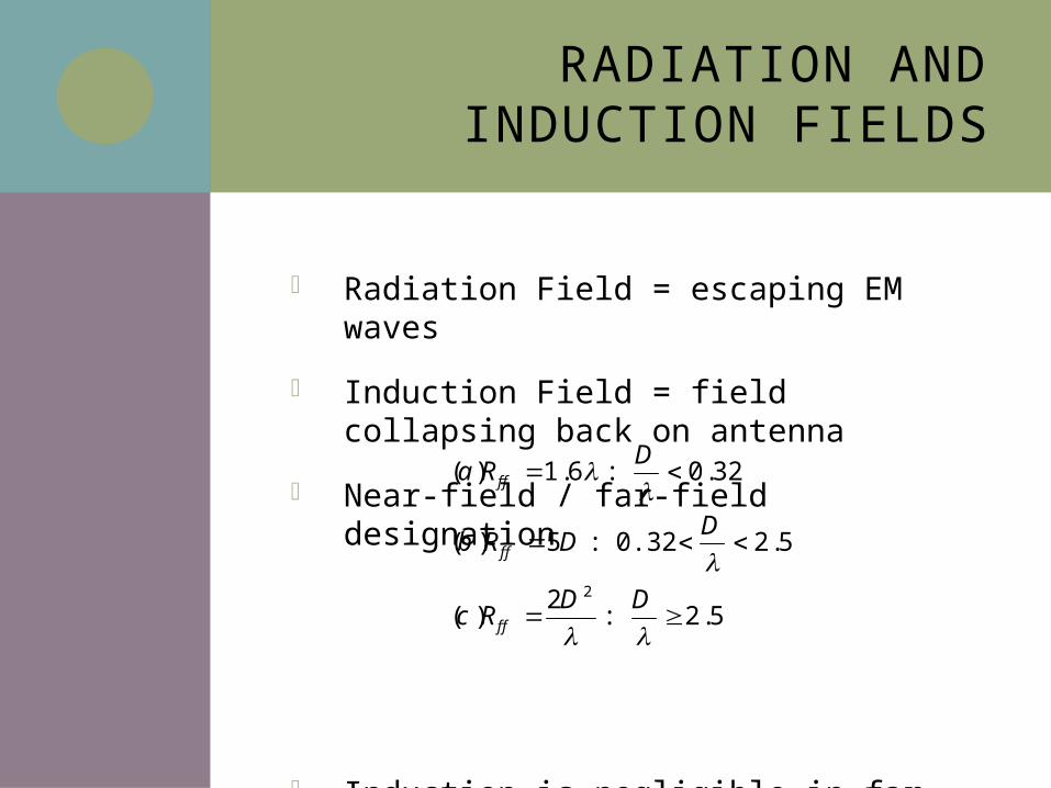
Radiation Field = escaping EM waves
Induction Field = field collapsing back on antenna
Near-field / far-field designation
Induction is negligible in far field
5.2 :2
)(
5.20.32 :5)(
32.0 :6.1)(
2
DDRc
DDRb
DRa
ff
ff
ff
RADIATION PATTERNS
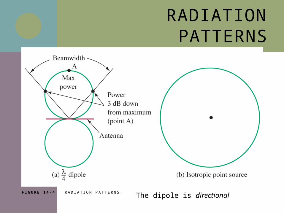
F I G U R E 1 4 - 4 R A D I AT I O N PAT T E R N S .The dipole is directional
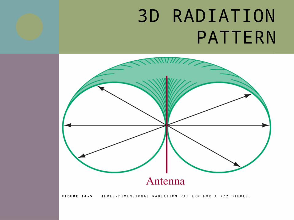
3D RADIATION PATTERN
F I G U R E 1 4 - 5 T H R E E - D I M E N S I O N A L R A D I AT I O N P AT T E R N F O R A / 2 D I P O L E .
ANTENNA GAIN
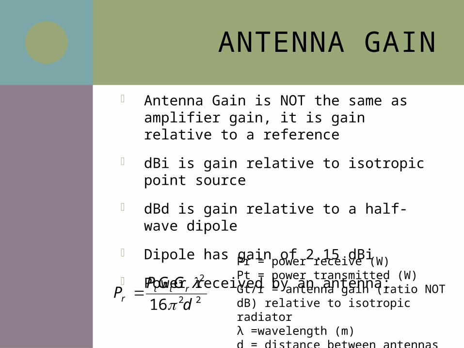
Antenna Gain is NOT the same as amplifier gain, it is gain relative to a reference
dBi is gain relative to isotropic point source
dBd is gain relative to a half-wave dipole
Dipole has gain of 2.15 dBi
Power received by an antenna:
22
2
16 dGGP
P rttr
Pr = power receive (W)Pt = power transmitted (W)Gt/r = antenna gain (ratio NOT dB) relative to isotropic radiatorλ =wavelength (m)d = distance between antennas (m)
14-3 RADIATION RESISTANCE
Effects of Antenna Length
Ground Effects
Electrical versus Physical Length
Effects of Nonideal Length
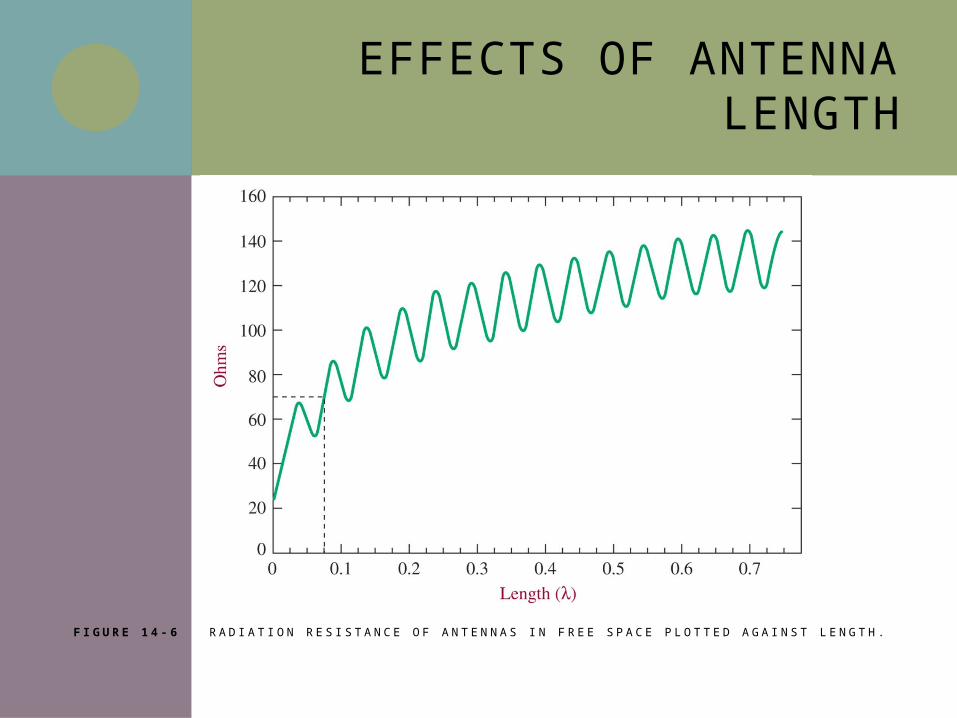
EFFECTS OF ANTENNA LENGTH
F I G U R E 1 4 - 6 R A D I AT I O N R E S I S TA N C E O F A N T E N N A S I N F R E E S PA C E P L O T T E D A G A I N S T L E N G T H .
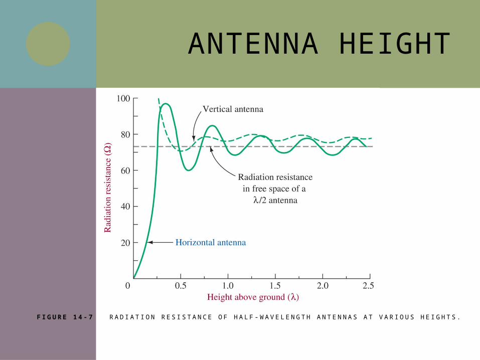
ANTENNA HEIGHT
F I G U R E 1 4 - 7 R A D I AT I O N R E S I S TA N C E O F H A L F - WAV E L E N G T H A N T E N N A S AT VA R I O U S H E I G H T S .
ELECTRICAL VS. PHYSICAL LENGTH
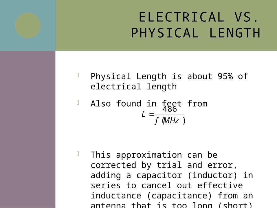
Physical Length is about 95% of electrical length
Also found in feet from
This approximation can be corrected by trial and error, adding a capacitor (inductor) in series to cancel out effective inductance (capacitance) from an antenna that is too long (short)
)(486MHzf
L
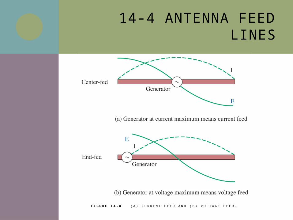
14-4 ANTENNA FEED LINES
F I G U R E 1 4 - 8 ( A ) C U R R E N T F E E D A N D ( B ) V O LTA G E F E E D .
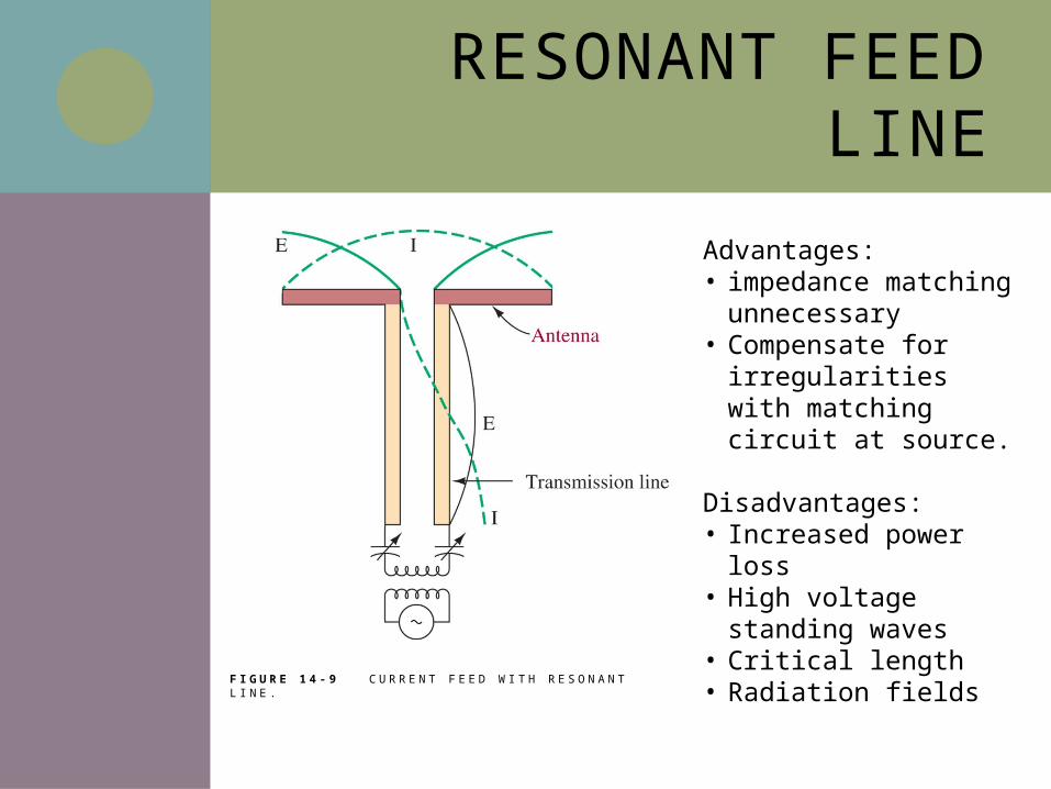
RESONANT FEED LINE
F I G U R E 1 4 - 9 C U R R E N T F E E D W I T H R E S O N A N T L I N E .
Advantages: • impedance matching
unnecessary• Compensate for
irregularities with matching circuit at source.
Disadvantages:• Increased power loss• High voltage standing
waves• Critical length• Radiation fields
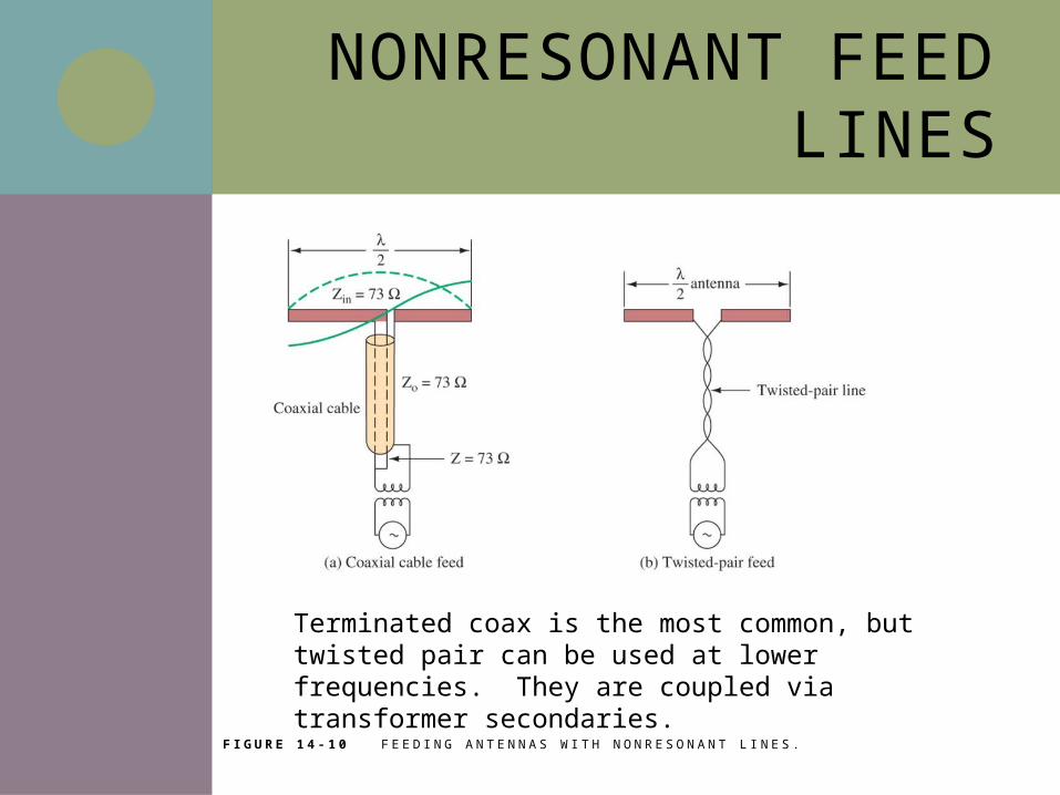
NONRESONANT FEED LINES
F I G U R E 1 4 - 1 0 F E E D I N G A N T E N N A S W I T H N O N R E S O N A N T L I N E S .
Terminated coax is the most common, but twisted pair can be used at lower frequencies. They are coupled via transformer secondaries.
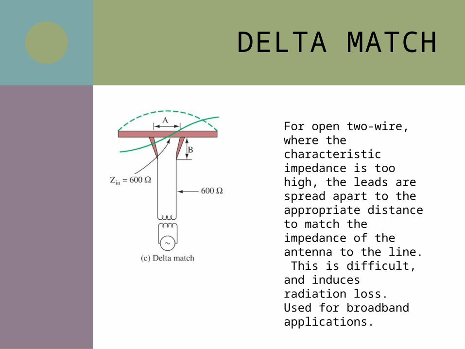
DELTA MATCH
For open two-wire, where the characteristic impedance is too high, the leads are spread apart to the appropriate distance to match the impedance of the antenna to the line. This is difficult, and induces radiation loss. Used for broadband applications.
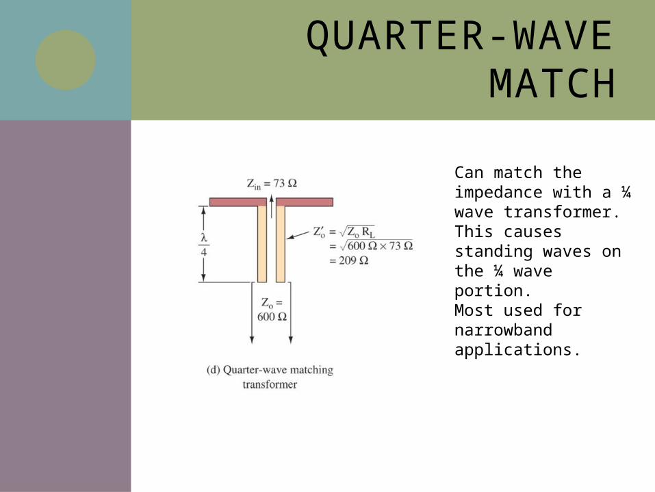
QUARTER-WAVE MATCH
Can match the impedance with a ¼ wave transformer. This causes standing waves on the ¼ wave portion. Most used for narrowband applications.
14-5 MONOPOLE ANTENNA
Effects of Ground Reflection
The Counterpoise
Radiation Pattern
Loaded Antennas
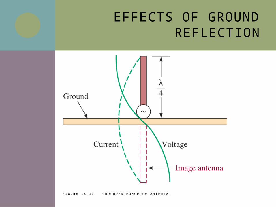
EFFECTS OF GROUND REFLECTION
F I G U R E 1 4 - 1 1 G R O U N D E D M O N O P O L E A N T E N N A .
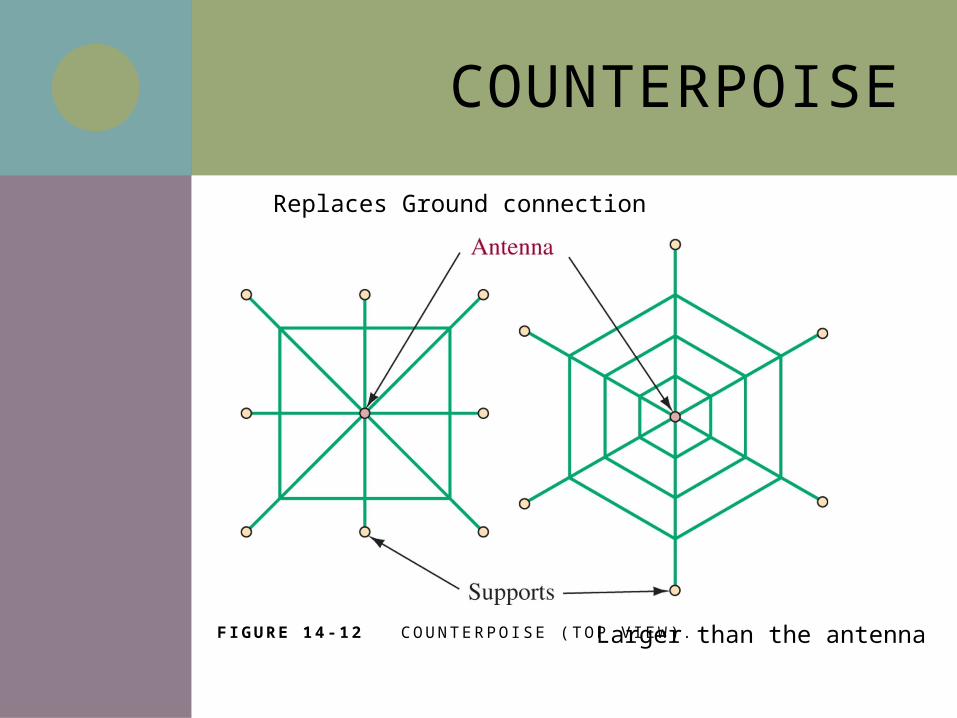
COUNTERPOISE
F IGURE 14 -12 C O U N T E R P O I S E ( T O P V I E W ) .Larger than the antenna
Replaces Ground connection
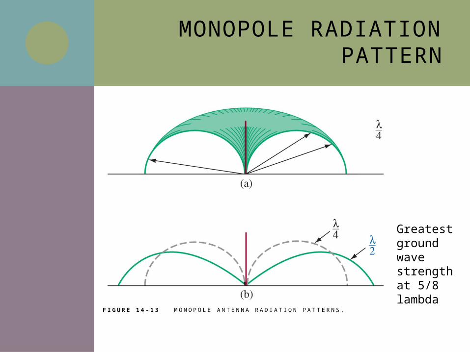
MONOPOLE RADIATION PATTERN
F I G U R E 1 4 - 1 3 M O N O P O L E A N T E N N A R A D I AT I O N PAT T E R N S .
Greatest ground wave strength at 5/8 lambda
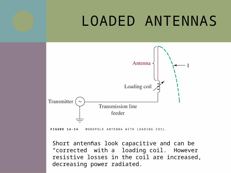
LOADED ANTENNAS
F I G U R E 1 4 - 1 4 M O N O P O L E A N T E N N A W I T H L O A D I N G C O I L .
Short antennas look capacitive and can be “corrected” with a loading coil. However resistive losses in the coil are increased, decreasing power radiated.
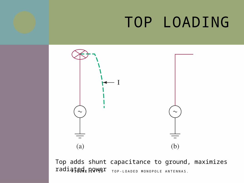
TOP LOADING
F I G U R E 1 4 - 1 5 T O P - L O A D E D M O N O P O L E A N T E N N A S .
Top adds shunt capacitance to ground, maximizes radiated power
14-6 ANTENNA ARRAYS
Half-Wave Dipole Antenna with Parasitic Element
Yagi-Uda Antenna
Driven Collinear Array
Broadside Array
Vertical Array
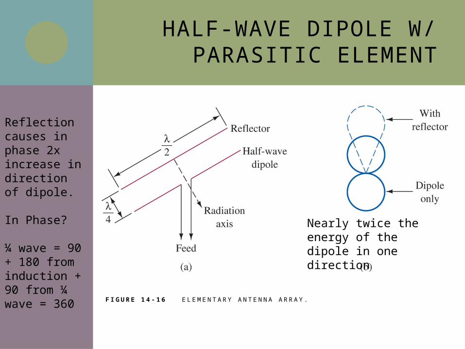
HALF-WAVE DIPOLE W/ PARASITIC ELEMENT
F I G U R E 1 4 - 1 6 E L E M E N TA RY A N T E N N A A R RAY.
Reflection causes in phase 2x increase in direction of dipole. In Phase?
¼ wave = 90 + 180 from induction + 90 from ¼ wave = 360
Nearly twice the energy of the dipole in one direction
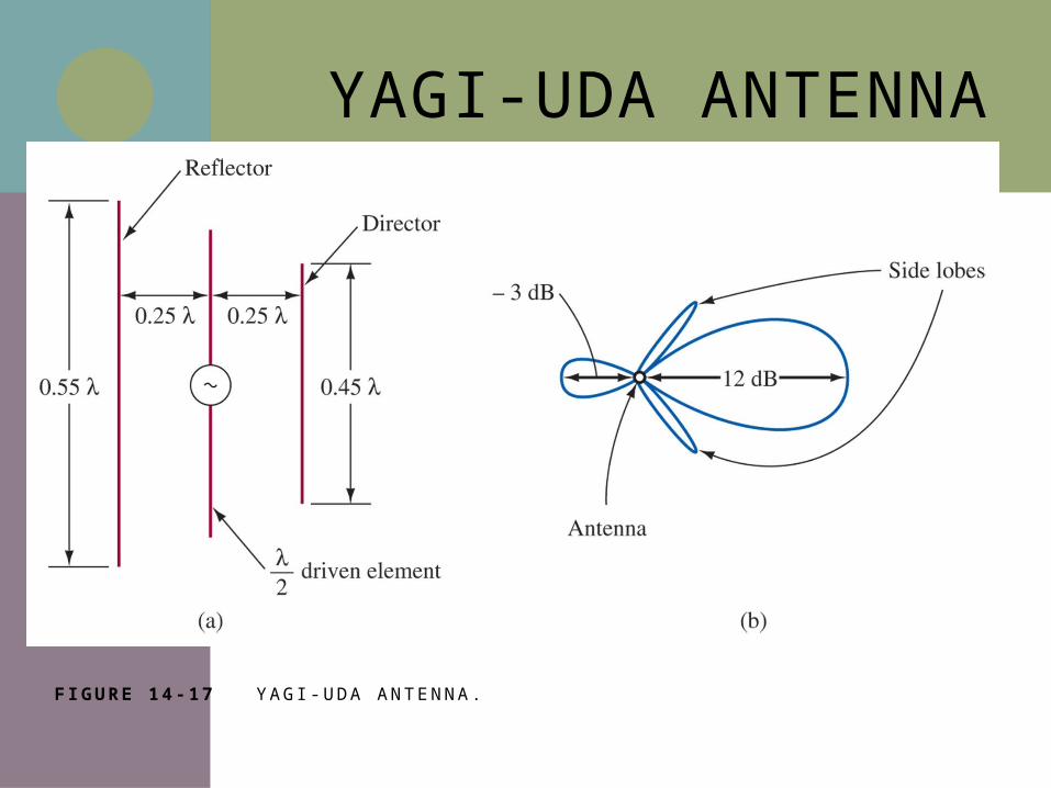
YAGI-UDA ANTENNA
F IGURE 14 -17 YAG I - U DA A N T E N N A.
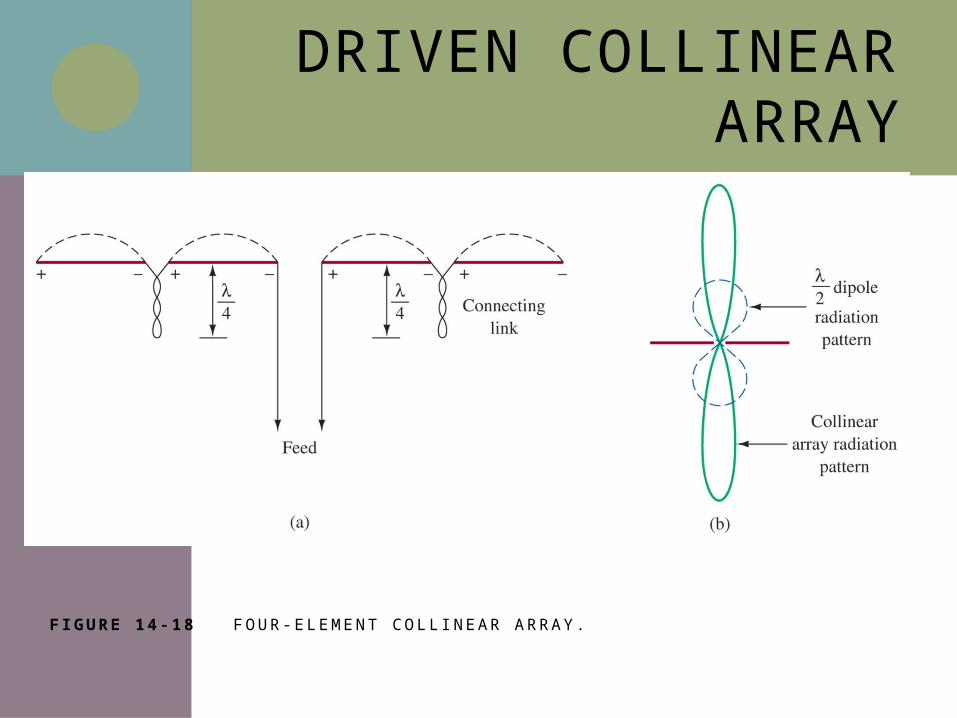
DRIVEN COLLINEAR ARRAY
F IGURE 14 -18 F O U R- E L E M E N T C O L L I N E A R A R RAY.
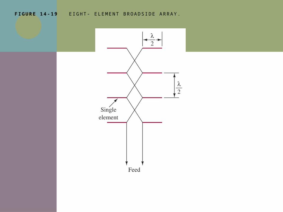
F IGURE 14 -19 E I G H T- E L E M E N T B R OA D S I D E A R RAY.
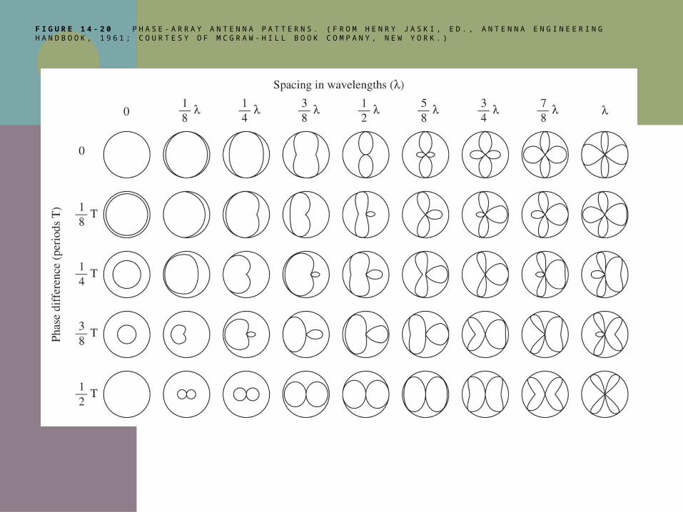
F I G U R E 1 4 - 2 0 P H A S E - A R R A Y A N T E N N A P A T T E R N S . ( F R O M H E N R Y J A S K I , E D . , A N T E N N A E N G I N E E R I N G H A N D B O O K , 1 9 6 1 ; C O U R T E S Y O F M C G R A W - H I L L B O O K C O M P A N Y , N E W Y O R K . )
14-7 SPECIAL-PURPOSE ANTENNAS
Log-Periodic Antenna
Small-Loop Antenna
Ferrite Loop Antenna
Folded Dipole Antenna
Slot Antenna
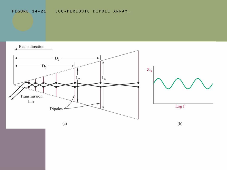
F IGURE 14 -21 LO G - P E R I O D I C D I P O L E A R RAY.
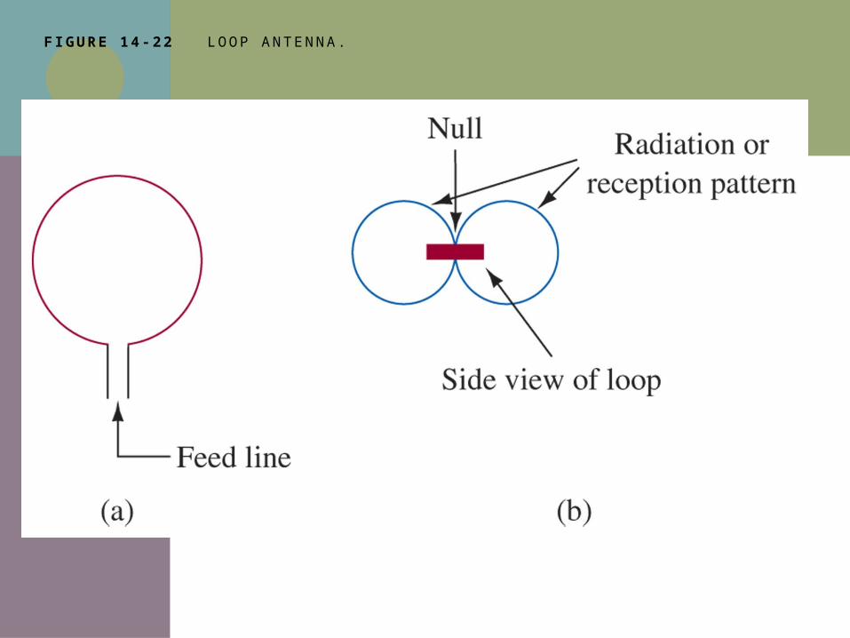
F IGURE 14 -22 LO O P A N T E N N A .
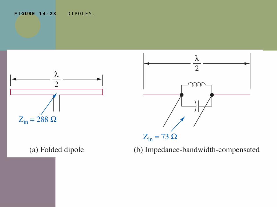
F IGURE 14 -23 D I P O L E S .
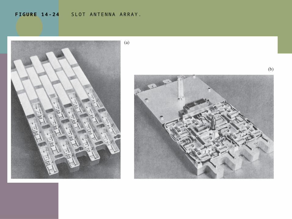
F IGURE 14 -24 S LO T A N T E N N A A R RAY.
ADVANCED ANTENNA DESIGN
Antennas can be very difficult in time and effort to design
They are often designed by trial-and-error methods
One of the newest and most unique methods being used is that of the “genetic algorithm”
YAGI-UDA GENETIC DESIGN
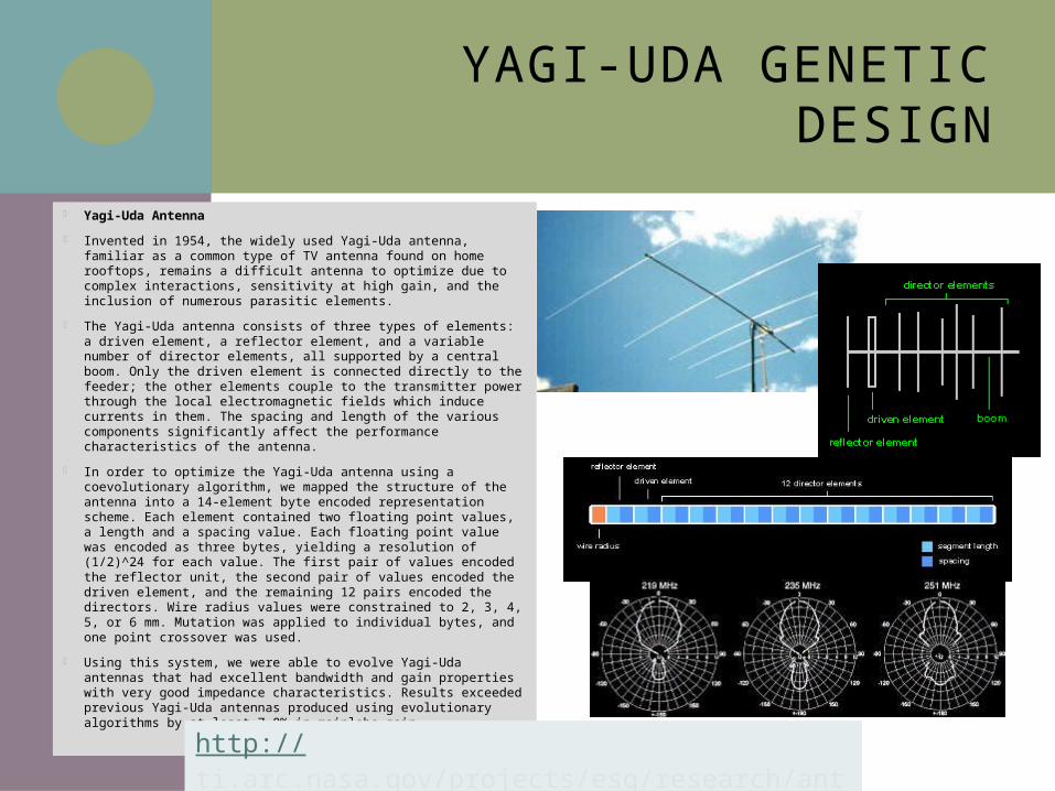
Yagi-Uda Antenna
Invented in 1954, the widely used Yagi-Uda antenna, familiar as a common type of TV antenna found on home rooftops, remains a difficult antenna to optimize due to complex interactions, sensitivity at high gain, and the inclusion of numerous parasitic elements.
The Yagi-Uda antenna consists of three types of elements: a driven element, a reflector element, and a variable number of director elements, all supported by a central boom. Only the driven element is connected directly to the feeder; the other elements couple to the transmitter power through the local electromagnetic fields which induce currents in them. The spacing and length of the various components significantly affect the performance characteristics of the antenna.
In order to optimize the Yagi-Uda antenna using a coevolutionary algorithm, we mapped the structure of the antenna into a 14-element byte encoded representation scheme. Each element contained two floating point values, a length and a spacing value. Each floating point value was encoded as three bytes, yielding a resolution of (1/2)^24 for each value. The first pair of values encoded the reflector unit, the second pair of values encoded the driven element, and the remaining 12 pairs encoded the directors. Wire radius values were constrained to 2, 3, 4, 5, or 6 mm. Mutation was applied to individual bytes, and one point crossover was used.
Using this system, we were able to evolve Yagi-Uda antennas that had excellent bandwidth and gain properties with very good impedance characteristics. Results exceeded previous Yagi-Uda antennas produced using evolutionary algorithms by at least 7.8% in mainlobe gain.http://ti.arc.nasa.gov/projects/esg/research/antenna.htm
GENETIC DESIGN OF MARS ODYSSEY UHF ANTENNA
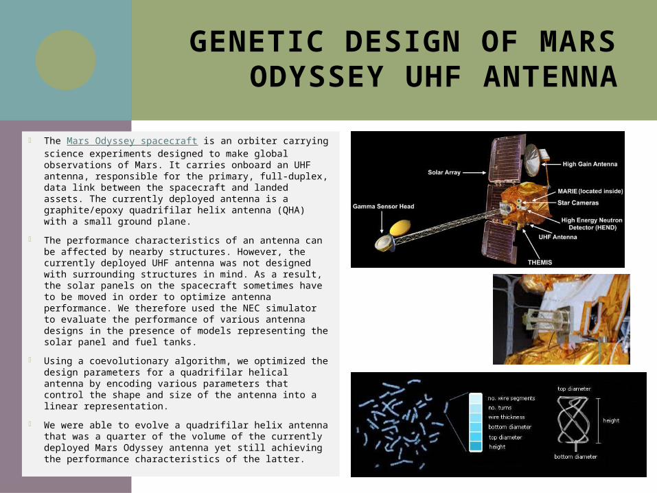
The Mars Odyssey spacecraft is an orbiter carrying science experiments designed to make global observations of Mars. It carries onboard an UHF antenna, responsible for the primary, full-duplex, data link between the spacecraft and landed assets. The currently deployed antenna is a graphite/epoxy quadrifilar helix antenna (QHA) with a small ground plane.
The performance characteristics of an antenna can be affected by nearby structures. However, the currently deployed UHF antenna was not designed with surrounding structures in mind. As a result, the solar panels on the spacecraft sometimes have to be moved in order to optimize antenna performance. We therefore used the NEC simulator to evaluate the performance of various antenna designs in the presence of models representing the solar panel and fuel tanks.
Using a coevolutionary algorithm, we optimized the design parameters for a quadrifilar helical antenna by encoding various parameters that control the shape and size of the antenna into a linear representation.
We were able to evolve a quadrifilar helix antenna that was a quarter of the volume of the currently deployed Mars Odyssey antenna yet still achieving the performance characteristics of the latter.
GENETIC DESIGN OF ST5 SATELLITE ANTENNA
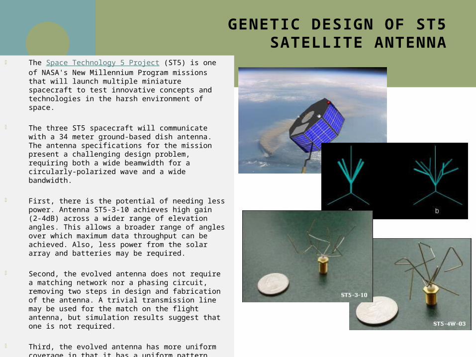
The Space Technology 5 Project (ST5) is one of NASA's New Millennium Program missions that will launch multiple miniature spacecraft to test innovative concepts and technologies in the harsh environment of space.
The three ST5 spacecraft will communicate with a 34 meter ground-based dish antenna. The antenna specifications for the mission present a challenging design problem, requiring both a wide beamwidth for a circularly-polarized wave and a wide bandwidth.
First, there is the potential of needing less power. Antenna ST5-3-10 achieves high gain (2-4dB) across a wider range of elevation angles. This allows a broader range of angles over which maximum data throughput can be achieved. Also, less power from the solar array and batteries may be required.
Second, the evolved antenna does not require a matching network nor a phasing circuit, removing two steps in design and fabrication of the antenna. A trivial transmission line may be used for the match on the flight antenna, but simulation results suggest that one is not required.
Third, the evolved antenna has more uniform coverage in that it has a uniform pattern with small ripples in the elevations of greatest interest (between 40 and 80 degrees). This allows for reliable performance as elevation angle relative to the ground changes.
Finally, the evolved antenna had a shorter design cycle. It was estimated that antenna ST5-3-10 took 3 person-months to design and fabricate the first prototype as compared to 5 person-months for the conventionally designed antenna.
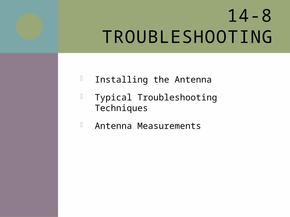
14-8 TROUBLESHOOTING
Installing the Antenna
Typical Troubleshooting Techniques
Antenna Measurements
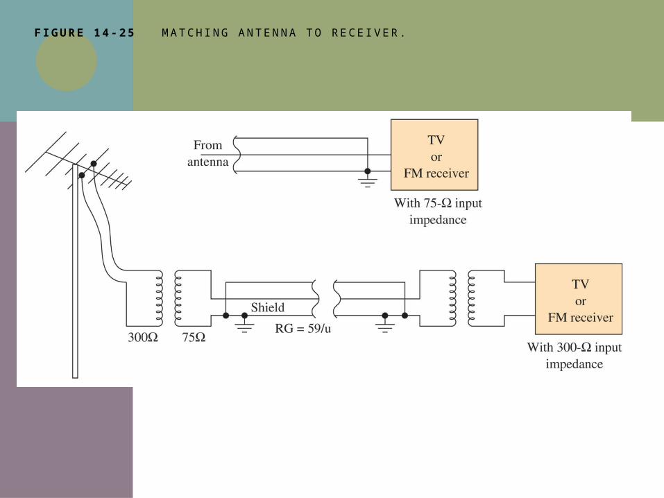
F IGURE 14 -25 M ATC H I N G A N T E N N A T O R E C E I V E R.
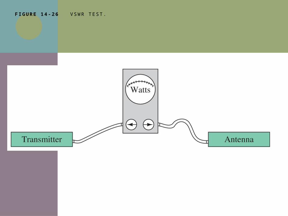
F IGURE 14 -26 V S W R T E S T.
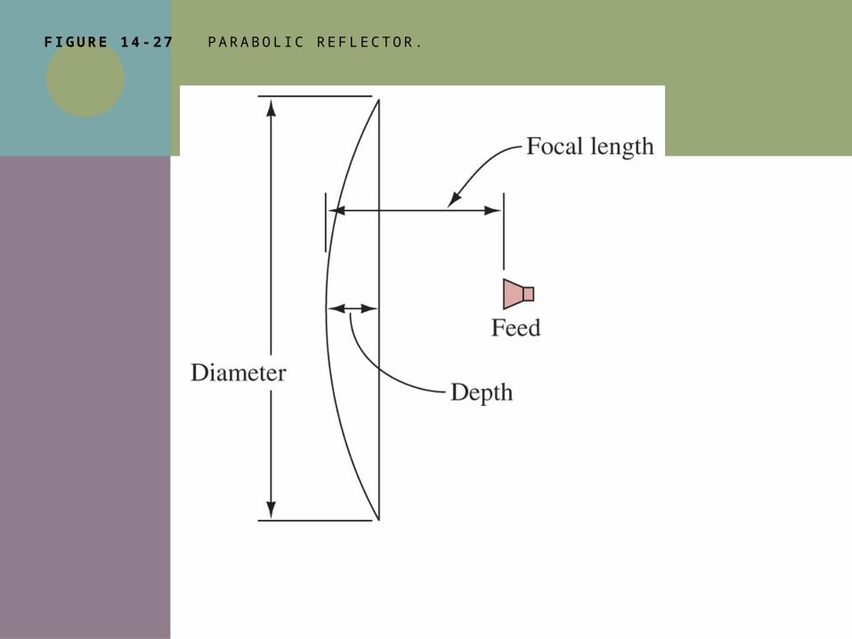
F IGURE 14 -27 PA RA BO L I C R E F L E C T O R.
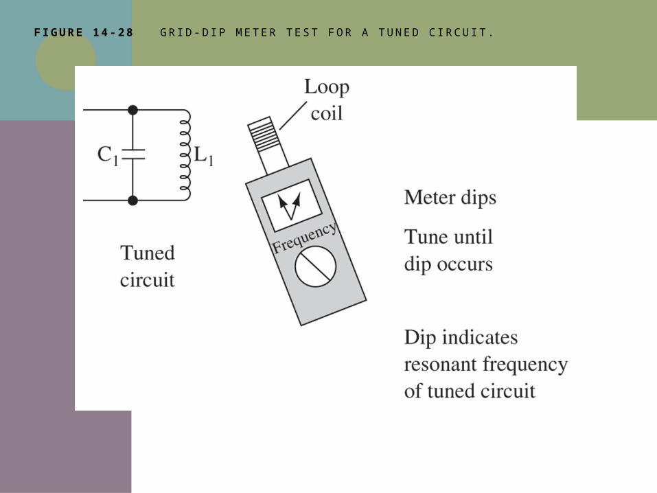
F IGURE 14 -28 G R I D - D I P M E T E R T E S T F O R A T U N E D C I RC U I T.
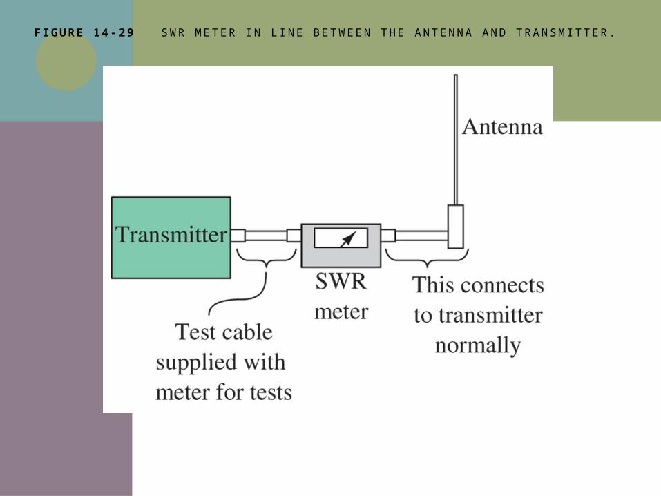
F IGURE 14 -29 S W R M E T E R I N L I N E B E T W E E N T H E A N T E N N A A N D T RA N S M I TT E R.
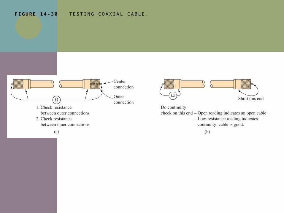
F IGURE 14 -30 T E S T I N G C OA X I A L C A B L E .
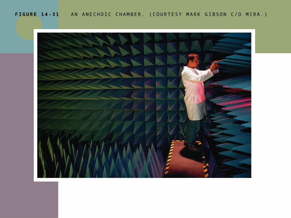
F IGURE 14 -31 A N A N E C H O I C C H A M B E R. ( C O U RT E S Y M A R K G I BS O N C / O M I RA . )

14-9 TROUBLESHOOTING W/ MULTISIM
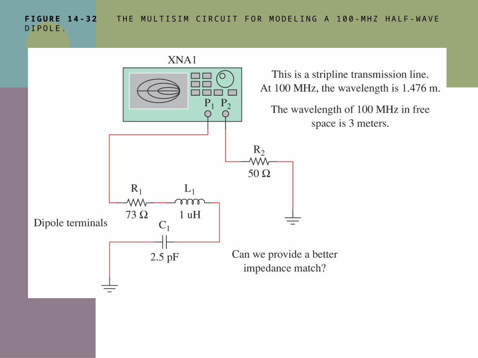
F IGURE 14 -32 T H E M U LT I S I M C I RC U I T F O R M O D E L I N G A 1 0 0 - M H Z H A L F -WAV E D I P O L E .
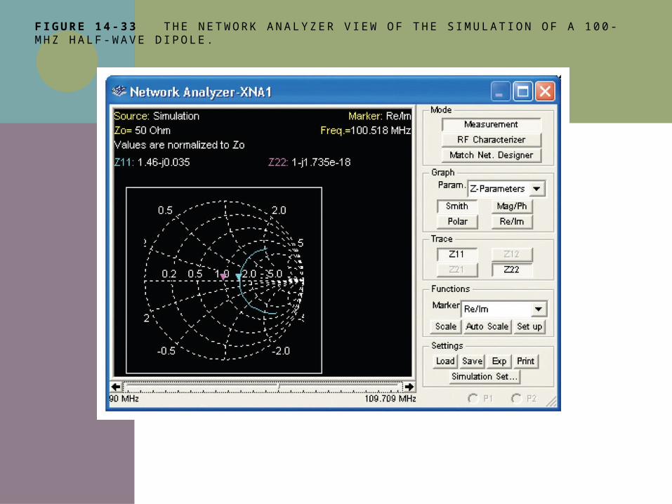
F IGURE 14 -33 T H E N E T W O R K A N A LY Z E R V I E W O F T H E S I M U L AT I O N O F A 1 0 0 -M H Z H A L F -WAV E D I P O L E .
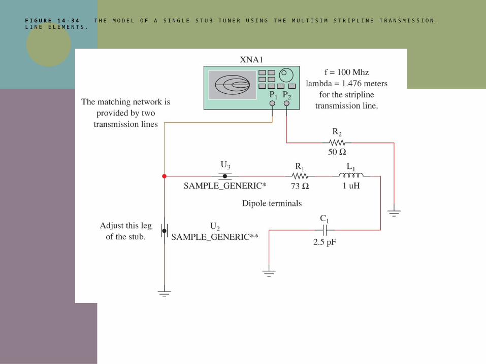
F I G U R E 1 4 - 3 4 T H E M O D E L O F A S I N G L E S T U B T U N E R U S I N G T H E M U LT I S I M S T R I P L I N E T R A N S M I S S I O N - L I N E E L E M E N T S .
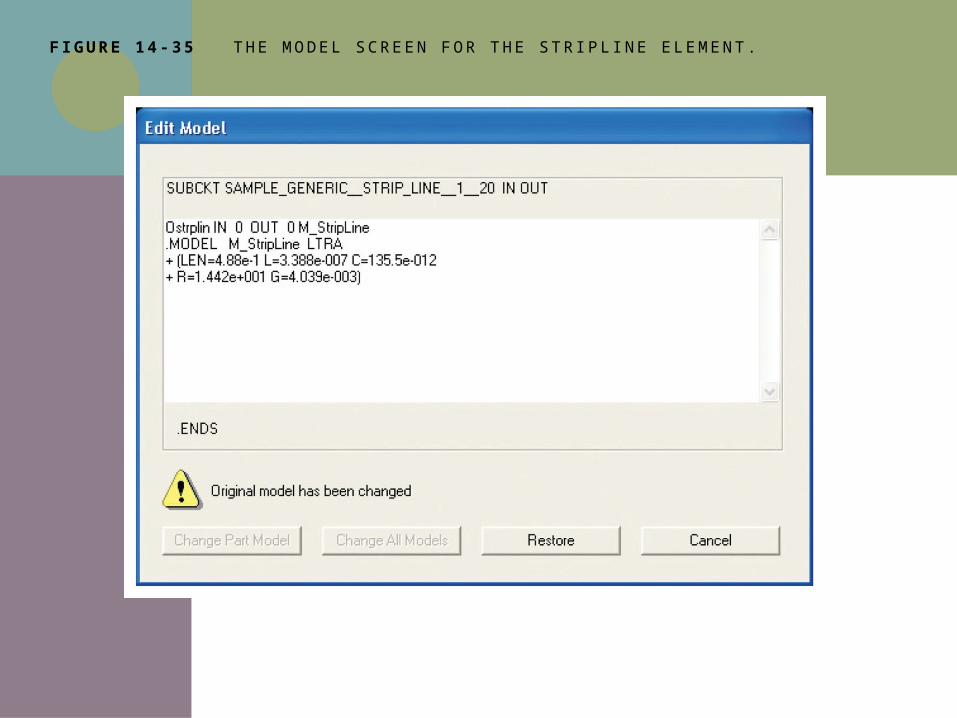
F IGURE 14 -35 T H E M O D E L S C R E E N F O R T H E S T R I P L I N E E L E M E N T.