2246 ieee transactions on wireless ...wcan.ee.psu.edu/papers/bg_twc_2014.pdfbetween the two networks...
TRANSCRIPT

2246 IEEE TRANSACTIONS ON WIRELESS COMMUNICATIONS, VOL. 13, NO. 4, APRIL 2014
Uplink Interference Management for CoexistingMIMO Femtocell and Macrocell Networks:
An Interference Alignment ApproachBasak Guler, Student Member, IEEE, and Aylin Yener, Senior Member, IEEE
Abstract—This paper considers uplink interference manage-ment for two-tier cellular systems by way of InterferenceAlignment (IA). In order to manage the uplink interferencecaused by macrocell users at the femtocell base stations (FBS),cooperation between macrocell users with the closest femtocellbase stations is proposed with the goal of aligning the receivedsignals of macrocell users in the same subspace at multiple FBSs.The precoder design for macrocell users is accomplished usingsuccessive semidefinite programming relaxations. The proposedsolution aims to minimize the cross-tier interference leaked to thefemtocells while providing the macrocell users with a minimumreceived signal to interference plus noise ratio (SINR) at themacrocell base station (MBS). Intra-tier femtocell interference isdealt with minimum mean squared error (MMSE) interferencesuppression. Numerical results demonstrate that the proposedtwo-tier interference management approach improves the perfor-mance of femtocell users, while maintaining the desired qualityof the communication channel of macrocell users.
Index Terms—Femtocells/small cells, two-tier networks, uplinkinterference management, interference alignment, MMSE inter-ference suppression.
I. INTRODUCTION
NEXT generation wireless networks are expected to pro-vide a diverse range of broadband services to meet
subscriber demands. Femtocells are a promising direction toimprove the performance for in-home users while reducingthe load on the cellular (macrocell) network [1]. Femtocellsrequire no infrastructure as they are plug-and-play devices thatare connected to the internet backhaul [2]. A main deploymentchallange is that femtocells operate in the licenced band, andconsequently have to share the radio resources and coexistwith the cellular network. Solutions proposed to guaranteecoexistence range from partitioning the frequency resourcesbetween the two networks with closed access, to allowingcellular (macrocell) users to be served by femtocell basestations with open access [1].
An alternative approach is to have users of a particular tierto be served by base stations of that tier, i.e., keeping theclosed access, while sharing all frequency resources across
Manuscript received August 1, 2013; revised November 27, 2013; acceptedJanuary 10, 2014. The associate editor coordinating the review of this paperand approving it for publication was T. J. Lim.
An earlier version of this work was presented in part at the IEEE GlobalCommunications Conference (GLOBECOM), December 2011.
The authors are with the Department of Electrical Engineering, ThePennsylvania State University, University Park, PA, 16802 USA (e-mail:[email protected]; [email protected]).
Digital Object Identifier 10.1109/TWC.2014.030314.131408
tiers. In such an architecture, in order to ensure peacefulcoexistence, effective management of cross-tier interference isof utmost importance. In the uplink, in particular, a macrocelluser operating in the same band as femtocell users maycause unacceptably high interference levels, if it is closeto the femtocell base station supporting the aforementionedfemtocell users, and far away from its own macrocell basestation. Additionally, the fact that femtocells can be deployedin an ad hoc fashion anywhere within a macrocell, and canbe removed as easily, adds to the critical importance ofinterference management. Notwithstanding the importance ofthis issue, the concerns listed above renders jointly optimaldesign of the two networks impractical due to the complex-ity and overhead associated with a large dynamic network.Consequently, a computationally manageable yet effectiveinterference management strategy is needed.
Interference management has been an important design ele-ment for multiuser systems in the past two decades. Judiciousreceiver design for interference limited systems, e.g., CDMA,and multiuser MIMO, proves useful for interference cancella-tion [3]. In addition to multiuser detection, transmit powercontrol [4], and joint design of transmitters and receivers[5], [6] offer interference mitigation needed in interferencelimited systems. Power control has also been an importantissue for co-existence of two-tier networks [7], [8]. While theaforementioned techniques have been designed primarily formulti-transmitter single receiver, i.e., multiple access systems,interference alignment has recently been proposed for multi-transmitter multi-receiver models, i.e., interference networks.
Interference Alignment (IA) has been shown to achievethe degrees of freedom for the K-user interference channel[9] by aligning the interfering signals in a lower dimensionalsubspace at multiple receivers simultaneously. Perfect IA formultiantenna systems has only been achieved for networkswith small number of users. Thus, for practical scenarios, i.e.,when K ≥ 4, distributed algorithms have been proposed toapproximately align the interference while allowing some in-terference leakage [10]–[12]. These algorithms are developedfor K-user interference channels, in which each transmitterhas a distinct intended receiver, and the remaining transmittersare considered as interferers for that receiver. As an example,the algorithms proposed in [10] use channel reciprocity, anditerate between the receivers and transmitters at each step, byreversing the communication direction as in [13], in order tominimize the leaked interference/maximize the SINR of the
1536-1276/14$31.00 c© 2014 IEEE

GULER and YENER: UPLINK INTERFERENCE MANAGEMENT FOR COEXISTING MIMO FEMTOCELL AND MACROCELL NETWORKS . . . 2247
intended signal, respectively. By contrast, our system modelis a two-tier system that consists of many interfering multipleaccess channels.
Interference alignment for femtocell networks has recentlybeen considered in settings different than ours, namely withorthogonal resource allocation. IA methods proposed for K-user interference channels have been used in [14] and [15] formitigating the intra-tier femtocell interference in the downlinkof a split-frequency femtocell-macrocell network, in whichmacrocell and femtocells are assigned separate frequencybands. The three user perfect interference alignment schemehas been utilized in [16] for managing the interference be-tween picocells and a macrocell. An adaptive subband parti-tioning method is proposed in [14] to mitigate the femtocell-to-femtocell interference, with each femtocell supporting asingle user. In this sense, the network model becomes sim-ilar to a K-user interference channel, to which interferencealignment techniques as proposed for the original single-tiernetwork can be applied. Reference [15] considers the intra-tier (femtocell-to-femtocell) interference management prob-lem in a downlink of a femtocell network, and studies thegame-theoretic strategies for femtocells. In this reference,orthogonal resource allocation is done which enables treatingthe femtocells forming a cluster as a K-user interferencechannel. By contrast, our scheme considers the inter-tier uplinkinterference management problem in a femtocell-macrocellnetwork, aligning the interfering signals of one tier at thereceivers of the other tiers, and multiple simultaneous users areallowed in each femtocell and the ensuing two-tier interferencealignment scheme. We note that while our approach does notinvolve explicit frequency partitioning between the tiers, i.e.,relies solely on the space dimensions, allowing for greaterflexibility, it is possible to have our scheme accompany afrequency partitioning scheme and increase the number ofuplink users sharing each subband as well. Our methodsassume cooperation amongst the femtocells within a clusterin a similar manner to cooperative multi-cell networks [17].For a detailed discussion on the impact of joint-cell decodingon the underlying backhaul we refer to [18], [19], and to[20] for an application of IA to multi-cell joint decoding. Thecoordination between the macrocell users and FBSs withineach cluster can be enabled by an access point that gathersthe channel state information of the dominant macrocell usersto design the macrocell user precoders and to notify each FBSin the cluster of its interference subspace. These access pointsmay be realized in a similar fashion to the femtocell accesspoints inherent in femtocell-macrocell networks.
In this paper, we take the viewpoint of managing theinterference caused by the macrocell users (transmitters) to theuplinks of femtocells in their vicinity by aligning their signalsat the right femtocell base stations (receivers). In order tomanage the uplink interference caused by the macrocell usersat the femtocell base stations (FBS), one can surmise usingjoint detection and interference cancellation. Given the poten-tial complexity and overhead, however, this global approachcan quickly become infeasible. We posit that a more viableapproach to this two-tier interference management problem isby leveraging the coordination between a group of FBS andthe macrocell users that are causing high interference to this
group of FBSs. Specifically, using the principle of interferencealignment (IA), we can align the received signals from thesemacrocell users in a lower dimensional subspace at multipleFBSs simultaneously, and use the remaining degrees of free-dom to improve the detection performance of the femtocellusers. While interference alignment helps the femtocell usersto eliminate macrocell interference, this should not come atthe expense of communication quality for the macrocell users.Our approach is to design the interference aligning precodersof macrocell users subject to individual SINR constraints attheir MBS, thus making sure they can communicate reliablywhile minimizing their interference to the femtocells.
Toward accomplishing our goal, we propose to align thereceived macrocell interference as much as possible subjectto minimum SIR constraints for each macrocell user (MU) atthe FBSs, by employing successive semidefinite programming(SDP) relaxations. After interference alignment, a precoding-decoding scheme is used at the FBSs to minimize the sumMSE of the femtocell users (FU), which we call the coor-dinated MMSE approach. For comparison purposes, we alsopropose employing a zero-forcing constraint in the minimumsum MSE problem in order to eliminate the leftover alignedmacrocell interference separately at each FBS, which we callthe coordinated zero-forcing approach.
Numerical results demonstrate the benefits of the proposedIA algorithm, and that these benefits increase as the number ofinterfering macrocell users increase. The number of macrocellusers that can be aligned simultaneously depends on theminimum SINR requirements at the MBS, more users can bealigned when the minimum SINR requirements are decreased.It is also observed that separately zero-forcing the leakedmacrocell interference can over-constrain the system, and thecoordinated MMSE approach where the leaked macrocellinterference and femtocell interference is jointly suppressedperforms better.
The remainder of the paper is organized as follows: InSection II, we introduce the system model. Interference align-ment for macrocell users using successive SDP relaxations ispresented in Section III. Section IV describes the precodingand decoding schemes for femtocell users. Numerical resultsare given in Section V. We conclude the paper in Section VI.
The notation used in the paper is as follows: We use lower(upper) bold case letters for vectors (matrices). XH is used todenote the Hermitian transpose, X† as the pseudo-inverse ofmatrix X, and ⊗ for the Kronecker product. ‖ � ‖ is the normof a complex scalar or vector. Finally, tr(X) represents thetrace of matrix X, and |S| is the cardinality of the set S.
II. SYSTEM MODEL
The cellular network considered in this paper is the uplinkof a co-existing macrocell-femtocell network with a singleMBS at the center with No receive antennas. Multiple FBSsare distributed over the macrocell coverage area1. The macro-cell coverage area is partitioned into smaller areas of fixedradius in which the mobile users and FBSs are assumed to beable and willing to cooperate with each other. These clusters
1We treat inter-macrocell interference as noise and concentrate on onemacrocell.
2248 IEEE TRANSACTIONS ON WIRELESS COMMUNICATIONS, VOL. 13, NO. 4, APRIL 2014
Macrocell Base Station
Femtocell Base Station
Macrocell User
Femtocell User
Fig. 1. System model with a single MBS and 4 femtocell clusters.
may represent a building or a neighborhood. We focus on aclosed access model in the sense that the macrocell users’communication is facilitated by the MBS. An instance of thenetwork model with 4 femtocell clusters is shown in Fig. 1.
We consider such a cluster with F FBSs, Uf FUs in thef th femtocell and M MUs. We assume Nt transmit antennasat each mobile device, MU or FU, and Nf receive antennas atthe f th FBS. The discrete time representation of the receivedsignal at the kth FBS is then given as:
yk=
Uk∑i=1
Hkkiw
ki s
ki︸ ︷︷ ︸
signals from kth
femtocell users
+
M∑m=1
Hokmwo
msom︸ ︷︷ ︸macrocell interference
+
F∑f=1f �=k
Uf∑u=1
Hfkuw
fus
fu
︸ ︷︷ ︸other femtocell interference
+nk
(1)where Ho
km represents the channel from the mth MU to thekth FBS, and Hf
ku is the channel from the uth user of the f th
femtocell to the kth FBS. wfu denotes the precoding vector of
the uth user of the f th femtocell, whereas wom represents the
precoding vector of the mth MU. The number of femtocells inthe macrocell coverage area is denoted by F . sfu is the messageof the uth user of the f th femtocell, and som representsthe message of the mth MU. We assume the messages sfuand som = ±1 with equal probability for u = 1, . . . , Uf ,f = 1, . . . , F , and m = 1, . . . ,M . The noise at the kth FBSis denoted by nk, which consists of independent zero-meanGaussian random variables with E{nknk
H} = σ2I. Similarly,the signal received at the MBS can be represented as:
yo =
M∑m=1
Hoomwo
msom︸ ︷︷ ︸signals from
macrocell users
+
F∑f=1
Uf∑u=1
Hfouw
fus
fu
︸ ︷︷ ︸femtocell interference
+no (2)
where Hoom is used to denote the channel from the mth
MU to the MBS, and Hfou is the channel from the the uth
user of the f th femtocell to the MBS. The noise at theMBS is no, consisting of independent zero-mean Gaussianrandom variables with E{nono
H} = σ2I. The channel state
FU 1
FU 2
MU 1
MU 2
FU 2
FBS 1
FBS 2
MBS
FU 1
H112
H111
H1o2
H121
H122
Ho11
Ho21
Ho12
Ho22
H211
H212
H2o1
H221
H222
Hoo1
Hoo2
H1o1
H2o2
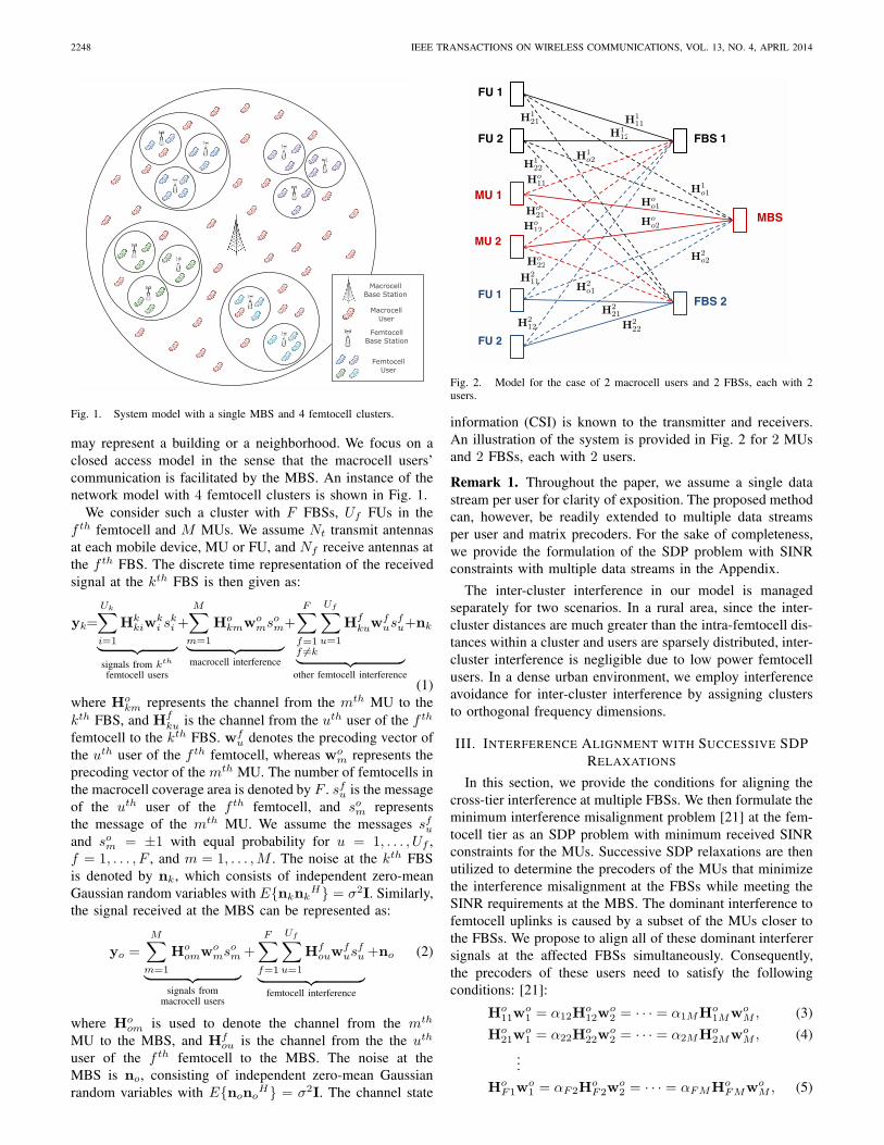
Fig. 2. Model for the case of 2 macrocell users and 2 FBSs, each with 2users.
information (CSI) is known to the transmitter and receivers.An illustration of the system is provided in Fig. 2 for 2 MUsand 2 FBSs, each with 2 users.
Remark 1. Throughout the paper, we assume a single datastream per user for clarity of exposition. The proposed methodcan, however, be readily extended to multiple data streamsper user and matrix precoders. For the sake of completeness,we provide the formulation of the SDP problem with SINRconstraints with multiple data streams in the Appendix.
The inter-cluster interference in our model is managedseparately for two scenarios. In a rural area, since the inter-cluster distances are much greater than the intra-femtocell dis-tances within a cluster and users are sparsely distributed, inter-cluster interference is negligible due to low power femtocellusers. In a dense urban environment, we employ interferenceavoidance for inter-cluster interference by assigning clustersto orthogonal frequency dimensions.
III. INTERFERENCE ALIGNMENT WITH SUCCESSIVE SDPRELAXATIONS
In this section, we provide the conditions for aligning thecross-tier interference at multiple FBSs. We then formulate theminimum interference misalignment problem [21] at the fem-tocell tier as an SDP problem with minimum received SINRconstraints for the MUs. Successive SDP relaxations are thenutilized to determine the precoders of the MUs that minimizethe interference misalignment at the FBSs while meeting theSINR requirements at the MBS. The dominant interference tofemtocell uplinks is caused by a subset of the MUs closer tothe FBSs. We propose to align all of these dominant interferersignals at the affected FBSs simultaneously. Consequently,the precoders of these users need to satisfy the followingconditions: [21]:
Ho11w
o1 = α12H
o12w
o2 = · · · = α1MHo
1MwoM , (3)
Ho21w
o1 = α22H
o22w
o2 = · · · = α2MHo
2MwoM , (4)
...
HoF1w
o1 = αF2H
oF2w
o2 = · · · = αFMHo
FMwoM , (5)

GULER and YENER: UPLINK INTERFERENCE MANAGEMENT FOR COEXISTING MIMO FEMTOCELL AND MACROCELL NETWORKS . . . 2249
where αfm is a constant, and the equations dictate thatall interfering users span the same column space at eachFBS for which they are a dominant interferer. That is, eachinterfering signal is represented by a linear combination ofother interfering signals. Conditions (3)-(5) can be combinedin a single matrix equation [21] by using the precoders andscaling coefficients:
Hw = 0 (6)
where H is an(M
∑Ff=1 Nf
)×(MNt) matrix with two non-zero matrix-elements in each row:
H =
⎡⎢⎢⎢⎢⎢⎢⎢⎢⎢⎢⎢⎣
Ho11 −α12H
o12 . . . 0
......
. . ....
Ho11 0 . . . −α1MHo
1M...
.... . .
...Ho
F1 −αF2HoF2 . . . 0
......
. . ....
HoF1 0 . . . −αFMHo
FM
⎤⎥⎥⎥⎥⎥⎥⎥⎥⎥⎥⎥⎦,
and
w =[wo
1T wo
2T wo
3T . . . wo
M−1T wo
MT]T
.
One approach for finding the interference aligning precodingmatrices is to drive the norm of this expression as close to zeroas possible as in (7), from which follows the notion of leastsquares approach for IA, proposed in [21]. We will follow thisapproach with a twist. Specifically, in addition to solving theleast squares problem for IA, we also wish to ensure that theMUs do not fall below their SINR requirements as measured atthe MBS. As a result, a new constrained optimization problemarises which we tackle by using semidefinite programmingrelaxations. That is to say, the norm minimization problemwith individual minimum SINR constraints for each MU willincorporate successive SDP relaxations [22] and rank-oneapproximations.
We propose the following optimization problem to find theuplink MU precoders:
minwo
1 ,...,woM
‖Hw‖s.t. SINRi ≥ γi
(woi )
Hwo
i ≤ Poi i = 1, . . . ,M
(7)
where Poi and γi denote the maximum transmit power and
minimum SINR threshold of MU i, respectively. We definethe received SINR of MU i at the MBS as:
SINRi =(wo
i )H(Ho
oi)HHo
oiwoi∑M
n=1n�=i
(won)
H(Hoon)
HHoonw
on + β + σ2
(8)
with
β =
F∑f=1
Uf∑u=1
(wfu)
H(Hf
ou)HHf
ouwfu (9)
where Hoon denotes the channel from the nth MU to the
MBS, and σ2 is the noise power. Observe that β denotes theinterference power from the FUs at the MBS.
Remark 2. Although β depends on the choice of FU pre-
coders, due to originating from a group of low power FUs, weshall assume that this dependence is not significant enough towarrant a joint optimization approach with the FU precoders2.We will verify this assumption numerically in Section Vby comparing different initializations. We will thus use βas an added noise term with variance equal to the averageaccumulated interference power from the FUs. �
Using the conditions in (7), the problem can be re-writtenas:
minwo
1,...,woM
tr(RW)
s.t. tr
((Roi − γi
∑n�=i
Ron)W
)≥ γi(σ
2 + β)
tr((diag(ei)⊗ I(Nt×Nt)
)W
) ≤ Poi
rank(W) = 1
W � 0, i = 1, . . . ,M
(10)
where R = HHH, W = wwH , Ron = (Hoon)
HHoon, Ron =
diag(en)⊗Ron. The vector en = [0 . . . 010 . . .0]T is an (M×1) unit vector with 1 as the nth element and zeros elsewhere.I(Nt×Nt) denotes the (Nt ×Nt) identity matrix. By relaxingthe rank-1 constraint, we obtain the semidefinite relaxation ofthe problem [23]:
minimizewo
1,...,woM
tr(RW)
subject to tr
((Roi − γi
∑n�=i
Ron)W
)≥ γi(σ
2 + β)
tr((diag(ei)⊗ I(Nt×Nt)
)W
) ≤ Poi
W � 0, i = 1, . . . ,M
(11)
The SDP in (11) can be solved effectively, for instance byusing SeDuMi [24]. In case the resulting solution has a higherrank than one, we can use the eigenvector approximation in[25], in which the vector w is approximated as the eigenvectorq1 corresponding to the largest eigenvalue of W, scaled bythe square root of the largest eigenvalue of W, λ1, i.e.,
W = wwH =∑i
λiqiqHi (12)
w ∼=√λ1q1. (13)
Following this step, the coefficients are determined fromconditions (3)-(5) [21], as given by:
αkm = (Hokmwo
m)†(Hok1w
o1) (14)
(Hokmwo
m)† = ((Hokmwo
m)H(Hokmwo
m))−1(Hokmwo
m)H (15)
Remark 3. (Feasibility of SDP) The objective function ofthe SDP problem in (11) is always bounded below by 0. Asa result, a solution exists for the successive SDP relaxationsas long as the feasible set is not empty, that is, the SINRconstraints are achievable for the given channel configurationsand the maximum transmit power constraints; see also SectionIV.C. �
2The design of these precoders does have a significant impact on theperformance of the FU themselves and will be addressed in Section IV.

2250 IEEE TRANSACTIONS ON WIRELESS COMMUNICATIONS, VOL. 13, NO. 4, APRIL 2014
Remark 4. (Feasibility of Perfect Interference Alignment)Feasibility of perfect IA has recently been considered in thecontext of K-user interference channels [26], [27], for whichthe IA conditions form a multivariate polynomial system. Inour formulation, the IA condition is equivalent to solving thelinear matrix equation in (6). The number of rows of H in (6)is:
Nrow = M
F∑f=1
Nf (16)
which corresponds to the number of equations to be solved.The number of columns Ncol is given as:
Ncol = MNt (17)
which is equal to the number of variables. Then the linearsystem is overdetermined when
Nrow > Ncol ⇒ MF∑
f=1
Nf > MNt. (18)
It is known that an exact solution does not exist for suchsystems, and that perfect IA is not feasible. That is why weapply the least squares approach to minimize the unalignedinterference. �
IV. PRECODER AND DECODER DESIGN FOR FEMTOCELL
USERS
In the previous sections, we have designed the MU pre-coders so that their interfering signals are aligned at the FBS,while keeping their SINR levels. In this section, we will designthe FU precoders and decoders.
A. Coordinated MMSE Approach
Femtocell users can either cooperate and contribute to inter-ference alignment, which increases the system complexity andthe load on the backhaul or they can try to improve their ownperformance by interference cancellation. We opt for the latter(see also Remark 2), and apply MMSE precoding/decoding forthe FUs, while considering the aligned interference receivedfrom the MUs. The decision statistic for the estimated bit ofthe jth user of the kth femtocell is:
skj =
Uk∑i=1
(gkj )
HHkkiw
ki s
ki +
M∑m=1
(gkj )
HHokmwo
msom
+
F∑f=1f �=k
Uf∑u=1
(gkj )
HHfkuw
fus
fu + (gk
j )Hnk (19)
where gkj is the decoding vector for the jth user of the
kth femtocell. Using the conditions in (3)-(5) and (19), theminimum sum MSE at the kth FBS can be formulated as:
minimizewk
1 ,...,wkUk
gk1 ,...,g
kUk
Uk∑j=1
E{‖skj − skj ‖2}
subject to (wkj )
Hwkj ≤ Pk
j j = 1, . . . , Uk
(20)
Algorithm 1 SDP-IA Algorithm with Coordinated MMSE1. Initialize the coefficients in (3)-(5) and construct H in (6).2. Initialize the MU and FU precoders with each element drawn
i.i.d. from the standard Gaussian distribution N (0, 1).3. Calculate β in (9).4. Set i = 0 and ε0 = ‖Hw‖.5. while εi > εtol do6. Set i = i+ 1.7. Solve the SDP in (11) to find W.8. Determine the MU precoders wo
1, . . . ,woM by using (13).
9. Update the coefficients using the conditions (14)-(15).10. Calculate ‖Hw‖ with the new precoders and coefficients.11. Set εi = εi−1 − ‖Hw‖.12. end while13. for k = 1, . . . , F do14. Initialize the FU decoders gk
1 , . . . , gkUk
by using N (0, 1).
15. Calculate the sum MSE, ξ =∑Uk
j=1 E{‖skj − skj ‖2},defined in (20), (21).
16. Set n = 0 and δ0 = ξ.17. while δn > δtol do18. Set n = n+ 1.19. Update the vectors gk
1 , . . . ,gkUk
:
gkj (n) =
( F∑f=1
Uf∑u=1
(Hfkuw
fu(n− 1))(Hf
kuwfu(n− 1))H
+M∑
m=1
(Hokmwo
m(n−1))(Hokmwo
m(n−1))H+σ2I
)−1
Hkkjw
kj (n−1)
20. Determine the FU precoders wk1 , . . . ,w
kUk
by fixinggk1 , . . . ,g
kUk
:
wkj (n)=
( Uk∑i=1
(Hkkj)
Hgki (n)(g
ki (n))
HHkkj+μk
j I
)−1
(Hkkj)
Hgkj (n)
21. Calculate ξ with the new precoder and decoders.22. Set δn = δn−1 − ξ.23. end while24. end for
We can also express (20) as:
minimizewk
1 ,...,wkUk
gk1 ,...,g
kUk
Uk∑j=1
[‖(gk
j )HHk
kjwkj − 1‖2
+
Uk∑i=1i�=j
‖(gkj )
HHkkiw
ki ‖2+
M∑m=1
‖(gkj )
HHokmwo
m‖2
+F∑
f=1f �=k
Uf∑u=1
‖(gkj )
HHfkuw
fu‖2 + ‖gk
j ‖2σ2
]
subject to (wkj )
Hwkj ≤ Pk
j j = 1, . . . , Uk
(21)where Pk
j is the maximum transmit power of the jth user ofthe kth femtocell.
The problem in (21) is jointly convex in wkj , j = 1, . . . , Uk,
if all gkj are fixed, and jointly convex in gk
j , j = 1, . . . , Uk, ifall wk
j are fixed. Thus, we can design an iterative algorithmby first fixing the decoding vectors and obtaining the precod-ing vectors, then fixing the precoding vectors to obtain thedecoding vectors. Such an iterative procedure for obtainingthe precoders and decoders is used in [28] for a multipleaccess MIMO channel. The resulting precoders-decoders are

GULER and YENER: UPLINK INTERFERENCE MANAGEMENT FOR COEXISTING MIMO FEMTOCELL AND MACROCELL NETWORKS . . . 2251
guaranteed to converge to a local optimum which applies inthe present setting as well. When the vectors gk
j are fixed,the resulting optimization problem is over the precoders wk
j ,j = 1, . . . , Uk, can be written as follows:
minimizewk
1 ,...,wkUk
Uk∑j=1
[‖(gk
j )HHk
kjwkj − 1‖2+
Uk∑i=1i�=j
‖(gkj )
HHkkiw
ki ‖2
+
M∑m=1
‖(gkj )
HHokmwo
m‖2+F∑
f=1f �=k
Uf∑u=1
‖(gkj )
HHfkuw
fu‖2
+‖gkj ‖2σ2
]subject to (wk
j )Hwk
j ≤ Pkj j = 1, . . . , Uk
(22)The KKT conditions for (22) are:
Stationarity:Uk∑i=1
(Hkkj)
Hgki (g
ki )
HHkkjw
kj
∗+μk
jwkj
∗−(Hkkj)
Hgkj =0
Complementary Slackness: μkj ((w
kj
∗)Hwk
j
∗ − P kj ) = 0
Dual feasibility: μkj ≥ 0 (23)
Primary feasibility: (wkj
∗)Hwk
j
∗ ≤ P kj
where j = 1, ..., Uk, and wkj∗
denotes the optimal value forwk
j . Using the KKT conditions in (23), we can obtain theoptimal precoding vectors for (22) as:
wkj
∗=
( Uk∑i=1
(Hkkj)
Hgki (g
ki )
HHkkj + μk
j I
)−1
(Hkkj)
Hgkj
(24)where μk
j is determined to satisfy the transmit power con-straint, i.e., (wk
j )Hwk
j = Pkj . Similarly, we fix the vectors
wkj for j = 1, . . . , Uk and obtain the KKT conditions for the
resulting problem, from which the optimal decoding vector forfixed precoders follows:
gkj
∗=
( F∑f=1
Uf∑u=1
(Hfkuw
fu)(H
fkuw
fu)
H
+
M∑m=1
(Hokmwo
m)(Hokmwo
m)H + σ2I
)−1
Hkkjw
kj
(25)
for j = 1, . . . , Uk. Equations (24) and (25) together yield oneiteration of alternating optimization. The SDP-IA algorithmwith coordinated MMSE, putting together our findings in thissection with that of Section III, is presented in Algorithm1. In the implementation of the algorithm, SDP-IA iterationsterminate when the improvements in the objective functionHw is less than the tolerance level εtol. Similarly, MMSEstage stops whenever the improvement in the sum MSE isless than δtol.
B. Coordinated Zero-Forcing Approach
In this section, we consider the scheme in which each FBSzero-forces the aligned macrocell interference in addition tominimizing the sum MSE of its own users3. A coordinatedzero-forcing beamforming was used for SINR maximizationin [30], with ideas from [31].
Using (3)-(5) and (19), we can formulate the problem atFBS k as:
minwk
1 ,...,wkUk
gk1 ,...,g
kUk
Uk∑j=1
[‖(gk
j )HHk
kjwkj − 1‖2+
Uk∑i=1i�=j
‖(gkj )
HHkkiw
ki ‖2
+F∑
f=1f �=k
Uf∑u=1
‖(gkj )
HHfkuw
fu‖2 + ‖gk
j ‖2σ2
]
subject to (gkj )
HHok1w
o1 = 0
(wkj )
Hwkj ≤ Pk
j j = 1, . . . , Uk
(26)where Pk
j denotes the maximum transmit power of the jth userof femtocell k. The zero-forcing constraint in (26) implies thatgkj should be in the null space of (Ho
k1wo1) [32], from which
we can define a decoding vector as:
gkj = U0
kvkj (27)
where [U0k U
1k]Λk Vk is obtained from the SVD of Ho
k1wo1
and the columns of U0k is a nullspace basis of Ho
k1wo1. Letting
(U0k)
HHkkj = Hk
kj , the problem in (26) is equivalent to:
minwk
1 ,...,wkUk
vk1 ,...,v
kUk
Uk∑j=1
[‖(vk
j )HHk
kjwkj − 1‖2 +
Uk∑i=1i�=j
‖(vkj )
HHkkiw
ki ‖2
+F∑
f=1f �=k
Uf∑u=1
‖(vkj )
HHfkuw
fu‖2 + ‖vk
j ‖2σ2
]
subject to (wkj )
Hwkj ≤ Pk
j j = 1, . . . , Uk
(28)Equation (28) is convex in wk
j when all vkj are fixed, and
convex in vkj when all wk
j are fixed. Thus, once again, we canutilize alternating minimization to obtain an iterative algorithmby first fixing the decoding matrices and determining theprecoding matrices, then fixing the precoding matrices toobtain the decoding matrices. When decoding matrices in (28)are fixed, the vectors vk
j are fixed as a consequence, and theresulting problem can be written as follows:
minwk
1 ,...,wkUk
Uk∑j=1
[‖(vk
j )HHk
kjwkj − 1‖2+
Uk∑i=1i�=j
‖(vkj )
HHkkiw
ki ‖2
+F∑
f=1f �=k
Uf∑u=1
‖(vkj )
HHfkuw
fu‖2+‖vk
j ‖2σ2
]
subject to (wkj )
Hwkj ≤ Pk
j j = 1, . . . , Uk
(29)
3This approach represents the part presented at Globecom 2011 [29].

2252 IEEE TRANSACTIONS ON WIRELESS COMMUNICATIONS, VOL. 13, NO. 4, APRIL 2014
The KKT conditions for (29) can be determined as:
Stationarity:Uk∑i=1
(Hkkj)
Hvki (v
ki )
HHkkjw
kj
∗+ μk
jwkj
∗ − (Hkkj)
Hvkj = 0
Complementary Slackness: μkj ((w
kj
∗)Hwk
j
∗ − P kj ) = 0
Dual feasibility: μkj ≥ 0 (30)
Primary feasibility: (wkj
∗)Hwk
j
∗ ≤ P kj
where j = 1, ..., Uk, and wkj∗
denotes the optimal value forwk
j . Using the KKT conditions in (30), we can obtain theoptimal precoding vectors for fixed decoders as:
wkj
∗=
( Uk∑i=1
(Hkkj)
Hvki (v
ki )
HHkkj + μk
j I
)−1
(Hkkj)
Hvkj
(31)with μk
j determined such that (wkj )
Hwkj = Pk
j . Similarly, wefix the precoders in (28) to obtain:
vkj
∗=
( F∑f=1
Uf∑u=1
(Hfkuw
fu)(H
fkuw
fu)
H + σ2I
)−1
Hkkjw
kj
(32)Thus, (31) and (32) together constitute one iteration of theminimum sum MSE with coordinated zero-forcing method.This method is employed with MU precoder design fromSection III to construct the SDP-IA with coordinated zero-forcing algorithm presented in Algorithm 2.
C. Convergence of the Two-Tier Interference ManagementScheme
In this section, we discuss the convergence of the proposedtwo-tier iterative interference management schemes. We startby considering the first stage, which aligns the macrocellinterference at the FBSs by designing the MU precoders.Convergence of successive semidefinite relaxations has beenshown in [22] from which we know that the objective functionwhich represents the amount of interference misalignmentreduces at each iteration. Since the term ‖Hw‖ is alsobounded below by zero, we can conclude that whenever theconstraints are feasible due to the channel configurations andthe minimum SINR constraints, the IA part of the algorithmconverges. We note that although the SDP relaxation is anapproximation to the original IA problem, the simulationresults suggest that the remnant interference after convergenceis negligible. After the precoders of the MUs are determined,the precoders-decoders of the FUs are obtained iteratively bysolving a problem of minimizing the sum MSE at each FBS.We know that the objective function, sum MSE, is againbounded below by zero and is decreasing at each iteration,thus we conclude that the second stage of the problem, i.e.,coordinated MMSE part, also converges. The coordinatedzero-forcing algorithm, which also minimizes the sum MSE,converges following a similar argument. Thus we concludethat the SDP-IA algorithm, either with coordinated MMSE orzero-forcing, is convergent whenever the individual problemsare feasible with the given channels, SINR requirements andmaximum power constraints.
Algorithm 2 SDP-IA Algorithm with Coordinated Zero-Forcing
1. Initialize the coefficients in (3)-(5), construct H from (6).2. Initialize the MU and FU precoders with each element drawn
i.i.d. from the standard Gaussian distribution N (0, 1).3. Calculate β in (9).4. Set i = 0 and ε0 = ‖Hw‖.5. while εi > εtol do6. Set i = i+ 1.7. Solve the SDP in (11) to find W.8. Determine the MU precoders wo
1, . . . ,woM by using (13).
9. Update the coefficients using the conditions (14)-(15).10. Calculate ‖Hw‖ with the new precoders and coefficients.11. Set εi = εi−1 − ‖Hw‖.12. end while13. for k = 1, . . . , F do14. Initialize the FU decoders gk
1 , . . . , gkUk
by using N (0, 1).
15. Calculate the sum MSE, ξ =∑Uk
j=1 E{‖skj − skj ‖2},as defined in (28).
16. Determine the null space U0k of Ho
k1wo1 at FBS k to form
(U0k)
HHkkj = Hk
kj .17. Set n = 0 and δ0 = ξ.18. while δn > δtol do19. Set n = n+ 1.20. Update the vectors vk
1 , . . . ,vkUk
:
vkj (n) =
( F∑f=1
Uf∑u=1
(Hfkuw
fu(n−1))(Hf
kuwfu(n−1))H
+ σ2I
)−1
Hkkjw
kj (n−1)
21. Fix vk1 , . . . ,v
kUk
and determine the FU precoderswk
1 , . . . ,wkUk
:
wkj (n)=
( Uk∑i=1
(Hkkj)
Hvki (n)(v
ki (n))
HHkkj+μk
j I
)−1
(Hkkj)
Hvkj (n)
22. Calculate ξ with the new precoder and decoders.23. Set δn = δn−1 − ξ.24. end while25. Determine the FU decoders gk
1 , . . . ,gkUk
by using (25),gkj = U0
kvkj .
26. end for
V. NUMERICAL RESULTS
Simulations are performed to compare the performance ofthe proposed SDP-IA macrocell IA algorithms (Algorithm1 and Algorithm 2) with a baseline setting in which MUsminimize their sum MSE at the MBS, without regard tothe FUs. Simulations use Rayleigh fading channels with thepath loss modeled according to the ITU-R channel model[33] specifications for femtocell and macrocell users. Noisepower is at −110dB. Power control at both MBS and FBSsis employed to compensate for the path loss. The maximumtransmit power is 1W and 1mW for the MUs and FUs,respectively.
We discuss two scenarios. First one is a suburban two-tiercellular network with a MBS that has a coverage radius of2km. A circular area with a radius of 150m, denoting thegroup of FBSs close to each other, is placed according to auniform distribution within the macrocell coverage area. MUsresiding in this area are to be aligned at every FBS within thegroup. 3 FBSs, each having 3 users and a coverage radius of30m, are placed using a uniform random distribution over the

GULER and YENER: UPLINK INTERFERENCE MANAGEMENT FOR COEXISTING MIMO FEMTOCELL AND MACROCELL NETWORKS . . . 2253
1 2 3 4 5 6 7 8 9 100
0.5
1
1.5
2
2.5
3
3.5
4
4.5
5x 10
5
iteration
leak
ed in
terf
eren
ce
succesive SDPrank1 approximation
Fig. 3. Convergence results of the SDP-IA algorithm.
3 4 5 6 7 8 9 100.1
0
0.1
0.2
0.3
0.4
0.5
0.6
Number of interfering macrocell users
Ave
rage
BE
R
SDPIA with coordinated ZFSDPIA with coordinated MMSEwithout IA
Fig. 4. Average BER of the femtocell users with and without SDP-IAalgorithm.
circular area. FBSs have 4 receive antennas, and each mobileuser, MU or FU, has 4 transmit antennas.
The convergence of the SDP-IA algorithm for 10 MUs anda minimum SINR requirement of 0.1 at the MBS is presentedin Fig. 3, both with and without the rank-1 approximation.The comparison of SDP-IA with coordinated MMSE, SDP-IA with coordinated zero forcing, and the case when no IA isapplied and MUs aim to maximize their own performance atthe MBS, is given in Fig. 4 in terms of average BER versus thenumber of MUs interfering to the femtocell cluster. The figuredemonstrates that IA improves the average BER compared tothe no-IA scheme, and that the performance of the coordinatedMMSE approach is better than the coordinated zero-forcingscheme. In effect, the additional zero-forcing ends up over-constraining the transceivers of FUs. By contrast, coordinatedMMSE manages the leaked interference from MUs jointlywith the femtocell interference. The number of MUs that canbe aligned via the SDP-IA algorithm for different minimumSINR requirements at the MBS is depicted in Fig. 5.
The average BER of the FUs with respect to the numberof interfering MUs for the SDP-IA with coordinated MMSE
2 3 4 5 6 7 8 9 100.1
0.2
0.3
0.4
0.5
0.6
0.7
0.8
0.9
1
Number of aligned macrocell users
Min
SIN
R r
equi
red
at th
e M
BS
Fig. 5. Number of macrocell users that can be aligned subject to min SINRrequirement at the MBS.
3 4 5 6 7 8 9 100
0.5
1
1.5
2
2.5
3
3.5
4
4.5x 10
4
Number of interfering macrocell users
Ave
rage
BE
R
Fig. 6. Average BER of the femtocell users with SDP-IA algorithm withMMSE precoding/decoding for femtocell users.
algorithm is given in Fig. 6, for a single femtocell cluster.From Fig. 6 it can be seen that the average BER of theFUs have decreased, correspondingly their performances haveimproved.
We present the impact of aggregate femtocell interferenceon the received SINR of each MU for various SINR constraintsin Fig. 7, by varying the number of MUs in each clusterto achieve different ratios of MU and FUs as the rationalefor Remark 2. In this figure, FU precoders are either chosenrandomly (which will not necessarily perform well for FUs),or optimized iteratively in a joint fashion with the MBSprecoders. Fig. 7 suggests that the aggregate interferencepower from FUs on the MUs is small, no matter how theFU tranceivers are chosen. This affirms our view on theasymmetry of the two-tier interference and allows us to utilizethe two stage interference management scheme for the designof FU and MU precoders instead of tackling jointly whichwould have necessitated a fully centralized implementation ofthe two tiers.
The second scenario we study is a dense urban cellular

2254 IEEE TRANSACTIONS ON WIRELESS COMMUNICATIONS, VOL. 13, NO. 4, APRIL 2014
2 4 6 8 10 12 14 16 18 200.02
0.03
0.04
0.05
0.06
0.07
0.08
0.09
0.1
0.11
iteration
rece
ived
SIN
R a
t the
MB
S
random FU tranceivers, r=10/9optimized FU tranceivers, r=10/9random FU tranceivers, r=8/9optimized FU tranceivers, r=8/9random FU tranceivers, r=6/9optimized FU tranceivers, r=6/9
γi=0.06, ∀ i
γi=0.08, ∀ i
γi=0.1, ∀ i
Fig. 7. The effect of aggregate femtocell user power to the received SINR atthe MBS vs. different channel realizations, r denotes the ratio of the macrocellinterferers to femtocell users.
system. In this model, the macrocell coverage area, a circlewith a 300m radius, is partitioned into 7 hexagonal cells usingdisjoint sets of orthogonal dimensions. Macrocell and femto-cell users that reside within a cell, i.e., orthogonal dimensiongroup, share a set of orthogonal dimensions separate fromother cells. These orthogonal dimensions can be in terms offrequency and time dimensions and do not interfere with eachother. The hexagonal cells are approximated by a circular areawith a radius of 100m. The system involves the outdoor MUswhich are denoted as pedestrians as well as indoor MUs. In-door macrocell interferers are denoted as dominant macrocellinterferers due to the fact that the interference caused by theseusers at the FBSs will be higher then the outdoor macrocellinterference, which may cause a significant degrade in the FUperformance. Within the macrocell area, we assume that thereare buildings with multiple apartment/offices and multiplefemtocells, which consists of the indoor macrocell and femto-cell users. Each of these buildings denotes a femtocell cluster.The scenario is depicted in Fig. 8. Each femtocell cluster, i.e.,indoor block is approximated by a circular area with a radiusof 80m. The yellow circles represent the femtocell coverageareas. As can be seen from Fig. 8, a single femtocell cluster ispresent in each orthogonal dimension group. In this second setof simulations, we consider the coordinated MMSE approachonly given its superior performance to the coordinated zero-forcing approach.
Fig. 9 represents such a system with 70 MUs, with 10macrocell interferers in each femtocell cluster consisting of3 FBSs with 3 FUs in each femtocell. An indoor MU,which causes very high interference to the FUs, is called adominant macrocell interferer. The outdoor macrocell interfer-ers/pedestrians are called the weak macrocell interferers. Thefigure shows the average BER of the FUs in the system versusthe number of dominant macrocell interferers per group, for afixed total of 70 MUs. For Figs. 10-12, all MUs are considereddominant interferers. In Fig. 10, we plot the BER of the FUsversus the number of MUs per cluster. In Fig. 11, the averageBER of the FUs versus FU transmit power is plotted forvarious number of MUs per cluster and is compared to thebaseline scheme without IA. The maximum received SINR
Fig. 8. Hexagonal model demonstrating the femtocell cluster formation andindoor/outdoor areas.
1 2 3 4 5 6 7 8 90
0.005
0.01
0.015
0.02
0.025
0.03A
vera
ge B
ER
Number of dominant macrocell interferers
Fig. 9. Average BER for femtocell users for a fixed number of macrocellusers.
3 4 5 6 7 8 90.015
0.02
0.025
0.03
Number of dominant macrocell interferers
Ave
rage
BE
R
Fig. 10. Average BER for femtocell users for a variable number of macrocellusers.

GULER and YENER: UPLINK INTERFERENCE MANAGEMENT FOR COEXISTING MIMO FEMTOCELL AND MACROCELL NETWORKS . . . 2255
0 0.01 0.02 0.03 0.04 0.05 0.06 0.07 0.08 0.09 0.10
0.05
0.1
0.15
0.2
0.25
0.3
0.35
0.4
0.45
0.5A
vera
ge B
ER
FU power (W)
IAMMSESDP, M=9without IA, M=9IAMMSESDP, M=8without IA, M=8IAMMSESDP, M=7without IA, M=7IAMMSESDP, M=6without IA, M=6
Fig. 11. Average BER of the femtocell users with and without SDP-IA-MMSE algorithm.
that can be achieved as the number of interfering MUs percluster increases is shown in Fig. 12. The average BER ofthe FUs for the coordinated MMSE approach is comparedto zero-forcing interference cancellation in Fig. 13 subjectto the number of receive antennas at the FBS, from whichwe observe the greater advantage of using IA in resourcelimited scenarios with smaller antenna numbers. Overall, thenumerical results demonstrate that the performance of the FUsin terms of average BER is significantly better when comparedto the case when the interfering MUs only consider theirown performance and minimize the sum MSE at the MBS.The feasibility of the minimum SINR constraints is a mainlimitation in this system: as the minimum SINR constraintsof MUs are increased, the maximum number of MUs that canbe aligned decreases.
VI. CONCLUSION
We have studied interference management for a two-tiernetwork with femtocells deployed within a macrocell. In par-ticular, we have opted for a design that mitigates interferencecaused by the MUs at multiple femtocell uplinks by using IA.Since, in this coexisting two-tiered network, interfering MUsneed to have their continued connectivity as well, we haveproposed an IA approach with individual SINR constraints,for which end we utilize successive SDP approximations toa quadratically constraint quadratic problem (QCQP). Thealgorithm is applied to mitigate uplink macrocell interferencein femtocell networks and numerical results are provided todemonstrate the effectiveness of the proposed design. Futuredirections include system level applications of the proposedalgorithms for analyzing their performance under standard-compliant scenarios, IA applications in tiered networks withreduced complexity, the impact of limited/noisy CSI, as wellas including the resource constraints of the backhaul in theinterference management problem.
APPENDIX: EXTENSION TO MULTIPLE DATA STREAMS
Assume that the precoder of MU j is given as Woj =
[woj1 . . . ,wo
jd] where d is the number of bit streams trans-mitted. Then conditions for IA at F FBSs can be given as:
2 3 4 5 6 7 8 9 100.1
0.2
0.3
0.4
0.5
0.6
0.7
0.8
0.9
1
Number of dominant macrocell interferers
Min
SIN
R r
equi
red
at th
e M
BS
Fig. 12. Number of MUs that can be aligned subject to minimum SINRrequirement at the MBS with the SDP-IA-MMSE algorithm.
0 5 10 15 20 25 300
0.02
0.04
0.06
0.08
0.1
0.12
0.14
0.16
0.18
0.2
Femtocell User Power (dBm)
Ave
rage
BE
R
ZF, Nr=4IAMMSE, Nr=4ZF, Nr=5IAMMSE, Nr=5ZF, Nr=6IAMMSE, Nr=6
Fig. 13. Average BER of the FUs for zero-forcing interference cancellationvs. SDP-IA-MMSE.
Hok1W
o1 ≺ Ho
k2Wo2 ≺ · · · ≺ Ho
kMWoM , k = 1, . . . , F (33)
where X ≺ Y shows that the column space of Y spans thatof X. Equivalently, the conditions in (33) can be expressedfor the FBSs k = 1, . . . , F as a system of linear equalities as:
Hok1w
o1i =
d∑j=1
αijkmHo
kmwomj , ∀m ∈ {2, . . . ,M} (34)
where αijkm is a scalar coefficient as in the one-dimensional
case. The linear system of equations can be represented fork = 1, . . . , F in vector form as follows:
(I(d×d) ⊗Hok1)w
o1 = (Akm ⊗Ho
km)wom, m = 2, . . . ,M
(35)where wo
m denotes the vectorized form of the precoder matrixWo
m, in other words, wom = [(wo
j1)T . . . , (wo
jd)T ]T . Akm
denotes the (d × d) coefficient matrix formed by assigningαijkm as the element at row i and column j. Then (6) can be
redefined for the multi-dimensional case as:
Hw = 0 (36)

2256 IEEE TRANSACTIONS ON WIRELESS COMMUNICATIONS, VOL. 13, NO. 4, APRIL 2014
where
w =[wo
1T wo
2T wo
3T . . . wo
M−1T wo
MT]T
(37)
H=
⎡⎢⎢⎢⎢⎢⎢⎢⎢⎢⎢⎢⎢⎢⎣
I(d×d) ⊗Ho11 −A12 ⊗Ho
12 . . . 0...
.... . .
...I(d×d) ⊗Ho
11 0 . . . −A1M ⊗Ho1M
......
. . ....
I(d×d) ⊗HoF1 −AF2 ⊗Ho
F2 . . . 0...
.... . .
...I(d×d) ⊗Ho
F1 0 . . . −AFM ⊗HoFM
⎤⎥⎥⎥⎥⎥⎥⎥⎥⎥⎥⎥⎥⎥⎦
Thus, the objective function of the SDP problem for multipledata streams is formulated. We now turn to the derivation ofthe new SINR constraints with matrix precoders. The SINRconstraint for MU i with precoder Wo
i is given as:
SINRi =tr((Wo
i )H(Ho
oi)HHo
oiWoi )∑M
n=1n�=i
tr((Won)
H(Hoon)
HHoonW
on) + β + σ2
(38)where Wo
n is the precoder of MU n and
β =
F∑f=1
Uf∑u=1
tr((Wfu)
H(Hf
ou)HHf
ouWfu) (39)
where Wfu denotes the precoder for FU u and β represents
the femtocell interference at the MBS. We start by re-writingthe term representing the received signal strength for MU u:
tr((Wo
n)H(Ho
on)HHo
onWon
)=
d∑j=1
tr((wo
nj)H(Ho
on)HHo
onwonj
)(40)
= (won)
H
(I(d×d) ⊗
((Ho
on)HHo
on
))wo
n (41)
= wH
(en ⊗ I(d×d) ⊗
((Ho
on)HHo
on
))w (42)
The SDP problem for users with multiple data streams cannow be formulated as:
minimizewo
1 ,...,woM
tr(RW)
subject to tr
((Roi − γi
∑n�=i
Ron)W
)≥ γi(σ
2 + β)
tr((diag(ei)⊗ I(Ntd×Ntd)
)W
) ≤ Poi
W � 0, i = 1, . . . ,M
(43)
where R = HHH, W = wwH and Ron = diag(en) ⊗I(d×d) ⊗ (
(Hoon)
HHoon
), ∀n. Interference alignment with
SINR constraints for multiple bit streams can therefore beformulated as an SDP problem with the appropriate modifica-tions. A detailed discussion on the properties of IA with leastsquares for multiple bit streams is available in [34].
REFERENCES
[1] V. Chandrasekhar, J. Andrews, and A. Gatherer, “Femtocell networks:a survey,” IEEE Commun. Mag., vol. 46, no. 9, pp. 59–67, Sept. 2008.
[2] Picochip, “The case for home base stations,” White Paper, Apr. 2007.[3] S. Verdu, Multiuser Detection. Cambridge University Press, 1998.
[4] R. Yates, “A framework for uplink power control in cellular radiosystems,” IEEE J. Sel. Areas Commun., vol. 13, no. 7, pp. 1341–1348,Sept. 1995.
[5] C. Rose, S. Ulukus, and R. Yates, “Wireless systems and interferenceavoidance,” IEEE Trans. Wireless Commun., vol. 1, no. 3, pp. 415–428,July 2002.
[6] W. M. Jang, B. R. Vojcic, and R. L. Pickholtz, “Joint transmitter-receiveroptimization in synchronous multiuser communications over multipathchannels,” IEEE Trans. Commun., vol. 46, pp. 269-278, Feb. 1998.
[7] H. Jo, C. Mun, J. Moon, and J. Yook, “Interference mitigation usinguplink power control for two-tier femtocell networks,” IEEE Trans.Wireless Commun., vol. 8, no. 10, pp. 4906–4910, Oct. 2009.
[8] V. Chandrasekhar and J. G. Andrews, “Uplink capacity and interfer-ence avoidance for two-tier femtocell networks,” IEEE Trans. WirelessCommun., vol. 8, no. 7, pp. 3498–3509, July 2009.
[9] V. R. Cadambe and S. A. Jafar, “Interference alignment and degrees offreedom region for the K user interference channel,” IEEE Trans. Inf.Theory, vol. 54, no. 8, Aug. 2008.
[10] K. S. Gomadam, V. R. Cadambe, and S. A. Jafar, “A distributed nu-merical approach to interference alignment and applications to wirelessinterference networks,” IEEE Trans. Inf. Theory, vol. 57, no. 6, pp.3309–3322, June 2011.
[11] D. A. Schmidt, C. Shi, R. A. Berry, M. L. Honig, and W. Utschick,“Minimum mean squared error interference alignment,” in Proc. 2009Asilomar Conf. Signals, Syst., Comput., pp. 1106–1110.
[12] S. W. Peters and R. W Heath, Jr., “Cooperative algorithms for MIMOinterference channels,” IEEE Trans. Veh. Technol., vol. 60, no. 1, pp.206–218, Jan. 2011.
[13] S. Ulukus and A. Yener, “Iterative transmitter and receiver optimizationfor CDMA networks,” IEEE Trans. Wireless Commun., vol. 3, no. 6,pp. 1974–1979, Nov. 2004.
[14] H. Lv, T. Liu, X. Hou, and C. Yang, “Adaptive interference alignmentfor femtocell networks,” in Proc. 2010 IEEE Int. Conf. Signal Process.
[15] F. Pantisano, M. Bennis, W. Saad, and M. Debbah, “Cooperativeinterference alignment in femtocell networks,” in Proc. 2011 IEEEGlobal Telecommun. Conf.
[16] W. Shin, W. Noh, K. Jang, and H. Choi, “Hierarchical interferencealignment for downlink heterogeneous networks,” IEEE Trans. WirelessCommun., vol. 11, no. 12, pp. 4549–4559, Dec. 2012.
[17] T. Weber, I. Maniatis, A. Sklavos, and Y. Liu, “Joint transmission anddetection integrated network (JOINT), a generic proposal for beyond 3Gsystems,” in Proc. 2002 Int. Conf. Telecommun., vol. 3, pp. 479–483.
[18] S. Shamai, O. Somekh, O. Simeone, A. Sanderovich, B. M. Zaidel, andH. V. Poor, “Cooperative multi-cell networks: impact of limited-capacitybackhaul and inter-users links,” in Proc. 2007 Int. Symp. Inf. Theory.
[19] O. Somekh, O. Simeone, A. Sanderovich, B. M. Zaidel, and S. Shamai,“On the impact of limited-capacity backhaul and inter-users links incooperative multicell networks,” in Proc. 2008 Conf. Inf. Sciences Syst.,pp. 776–780.
[20] S. Chatzinotas and B. Ottersten, “Interference alignment for clusteredmulticell joint decoding,” in Proc. 2011 IEEE Wireless Commun. Netw.Conf., pp. 1966–1971.
[21] H. Yu and Y. Sung, “Least squares approach to joint beam design forinterference alignment in multiuser multi-input multi-output interferencechannels,” IEEE Trans. Signal Process., vol. 58, no. 9, Sept. 2010.
[22] M. Kojima and L. Tuncel, “On the finite convergence of successive SDPrelaxation methods,” European J. Operations Research, 1999.
[23] S. Boyd and L. Vandenberghe, Convex Optimization. Cambridge Uni-versity Press, 2004.
[24] D. Peaucelle, D. Henrion, Y. Labit, and K. Taitz, Users Guide forSeDuMi Interface 1.04. LAAS-CNRS, 2002.
[25] Z. Luo, W. Ma, A. M. So, Y. Ye, and S. Zhang, “Semidefinite relaxationof quadratic optimization problems,” IEEE Signal Process. Mag., vol.27, no. 3, pp. 20–34, May 2010.
[26] C. M. Yetis, T. Gou, S. A. Jafar, and A. H. Kayran, “On feasibility ofinterference alignment in MIMO interference networks,” IEEE Trans.Signal Process., vol. 58, no. 9, pp. 4771–4782, Sept. 2010.
[27] G. Bresler, D. Cartwright, and D. Tse, “Settling the feasibility of inter-ference alignment for the MIMO interference channel: the symmetricsquare case,” ITW, Brazil, 2011.
[28] S. Serbetli and A. Yener, “Transceiver optimization for multiuser MIMOsystems,” IEEE Trans. Signal Process., vol. 52, no. 1, pp. 214–226, Jan.2004.
[29] B. Guler and A. Yener, “Interference alignment for cooperative MIMOfemtocell networks,” in Proc. 2011 IEEE Global Telecommun. Conf.,pp. 1–5.

GULER and YENER: UPLINK INTERFERENCE MANAGEMENT FOR COEXISTING MIMO FEMTOCELL AND MACROCELL NETWORKS . . . 2257
[30] X. Sun, L. J. Cimini, L. J. Greenstein, D. S. Chant, and J. Kruys,“Coordinated zero-forcing beamforming in multipoint MIMO networksfor backhaul applications,” in Proc. 2009 IEEE Military Commun. Conf.
[31] Z. Pan, K.-K. Wong, and T.-S. Ng, “Generalized multiuser orthogonalspace-division multiplexing,” IEEE Trans. Wireless Commun., vol. 3,no. 6, pp. 1969–1973, Nov. 2004.
[32] Q. H. Spencer, A. L. Swindlehurst, and M. Haardt, “Zero-forcing meth-ods for downlink spatial multiplexing in multiuser MIMO channels,”IEEE Trans. Signal Process., vol. 52, no. 2, pp. 461–471, Feb. 2004.
[33] ITU-R Recommendation M.1225: “Guidelines for evaluation of radiotransmission technologies for IMT-2000,” Feb. 1997.
[34] H. Yu, Y. Sung, H. Kim, and Y. H. Lee, “Beam tracking for interferencealignment in slowly-fading MIMO interference channels: a perturbationsapproach under a linear framework,” IEEE Trans. Signal Process., vol.60, no. 4, pp. 1910–1926, Apr. 2012.
Basak Guler (S’13) received her B.Sc. degree inelectrical and electronics engineering from MiddleEast Technical University (METU), Ankara, Turkeyin 2009 and her M.Sc. degree in electrical engineer-ing from Wireless Communications and NetworkingLaboratory, Pennsylvania State University, Univer-sity Park, PA, in 2012. She is currently pursuingthe Ph.D. degree with the Wireless Communicationsand Networking Laboratory, Pennsylvania State Uni-versity. Her research interests include interferencemanagement in heterogeneous wireless networks,
femtocell-macrocell communication systems, semantic source coding, datacompression and semantic information theory.
Aylin Yener (S’91-M’00-SM’13) received the B.Sc.degree in electrical and electronics engineering, andthe B.Sc. degree in physics, from Bogazici Uni-versity, Istanbul, Turkey; and the M.S. and Ph.D.degrees in electrical and computer engineering fromWireless Information Network Laboratory (WIN-LAB), Rutgers University, New Brunswick, NJ.Commencing fall 2000, for three semesters, she wasa P.C. Rossin Assistant Professor at the Electri-cal Engineering and Computer Science Department,Lehigh University, PA. In 2002, she joined the
faculty of The Pennsylvania State University, University Park, PA, whereshe was an Assistant Professor, then Associate Professor, and is currentlyProfessor of Electrical Engineering since 2010. During the academic year2008-2009, she was a Visiting Associate Professor with the Department ofElectrical Engineering, Stanford University, CA. Her research interests are ininformation theory, communication theory and network science, with recentemphasis on green communications and information security. She receivedthe NSF CAREER award in 2003.
Dr. Yener previously served as a technical program chair or co-chair forvarious conferences for the IEEE Communications Society, as an associateeditor for the IEEE TRANSACTIONS ON COMMUNICATIONS, as an associateeditor and an editorial advisory board member for the IEEE TRANSACTIONS
ON WIRELESS COMMUNICATIONS. She served as the student committee chairfor the IEEE Information Theory Society 2007-2011, and was the co-founderof the Annual School of Information Theory in North America co-organizingthe school in 2008, 2009 and 2010. Dr. Yener currently serves on the boardof governors of the IEEE Information Theory Society as its treasurer.