2.3 molded case circuit breakers - grainger industrial …€™s molded case circuit breakers are...
TRANSCRIPT
V4-T2-116 Volume 4—Circuit Protection CA08100005E—October 2015 www.eaton.com
2
2
2
2
2
2
2
2
2
2
2
2
2
2
2
2
2
2
2
2
2
2
2
2
2
2
2
2
2
2
2.3 Molded Case Circuit Breakers
Series C
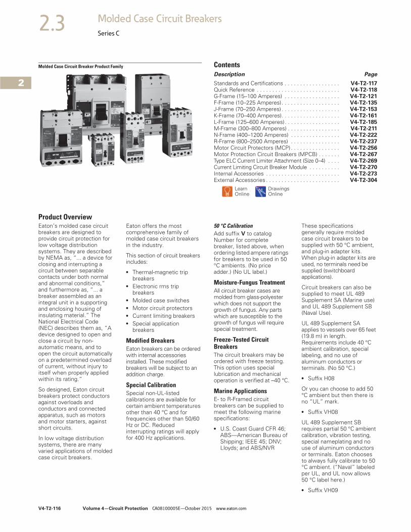
Molded Case Circuit Breaker Product Family ContentsDescription Page
Standards and Certifications . . . . . . . . . . . . . . . . . . V4-T2-117Quick Reference . . . . . . . . . . . . . . . . . . . . . . . . . . . V4-T2-118G-Frame (15–100 Amperes) . . . . . . . . . . . . . . . . . . V4-T2-121F-Frame (10–225 Amperes). . . . . . . . . . . . . . . . . . . V4-T2-135J-Frame (70–250 Amperes) . . . . . . . . . . . . . . . . . . . V4-T2-153K-Frame (70–400 Amperes). . . . . . . . . . . . . . . . . . . V4-T2-161L-Frame (125–600 Amperes). . . . . . . . . . . . . . . . . . V4-T2-185M-Frame (300–800 Amperes) . . . . . . . . . . . . . . . . . V4-T2-211N-Frame (400–1200 Amperes) . . . . . . . . . . . . . . . . V4-T2-222R-Frame (800–2500 Amperes) . . . . . . . . . . . . . . . . V4-T2-237Motor Circuit Protectors (MCP) . . . . . . . . . . . . . . . . V4-T2-256Motor Protection Circuit Breakers (MPCB) . . . . . . . V4-T2-267Type ELC Current Limiter Attachment (Size 0–4) . . . . V4-T2-269Current Limiting Circuit Breaker Module . . . . . . . . . . V4-T2-270Internal Accessories . . . . . . . . . . . . . . . . . . . . . . . . V4-T2-273External Accessories . . . . . . . . . . . . . . . . . . . . . . . . V4-T2-304
LearnOnline
DrawingsOnline
Product OverviewEaton’s molded case circuit breakers are designed to provide circuit protection for low voltage distribution systems. They are described by NEMA as, “... a device for closing and interrupting a circuit between separable contacts under both normal and abnormal conditions,” and furthermore as, “... a breaker assembled as an integral unit in a supporting and enclosing housing of insulating material.” The National Electrical Code (NEC) describes them as, “A device designed to open and close a circuit by non-automatic means, and to open the circuit automatically on a predetermined overload of current, without injury to itself when properly applied within its rating.”
So designed, Eaton circuit breakers protect conductors against overloads and conductors and connected apparatus, such as motors and motor starters, against short circuits.
In low voltage distribution systems, there are many varied applications of molded case circuit breakers.
Eaton offers the most comprehensive family of molded case circuit breakers in the industry.
This section of circuit breakers includes:
● Thermal-magnetic trip breakers
● Electronic rms trip breakers
● Molded case switches● Motor circuit protectors● Current limiting breakers● Special application
breakers
Modified BreakersEaton breakers can be ordered with internal accessories installed. These modified breakers will be subject to an addition charge.
Special CalibrationSpecial non-UL-listed calibrations are available for certain ambient temperatures other than 40 °C and for frequencies other than 50/60 Hz or DC. Reduced interrupting ratings will apply for 400 Hz applications.
50 °C CalibrationAdd suffix V to catalog Number for complete breaker, listed above, when ordering listed ampere ratings for breakers to be used in 50 °C ambients. (No price adder.) (No UL label.)
Moisture-Fungus TreatmentAll circuit breaker cases are molded from glass-polyester which does not support the growth of fungus. Any parts which are susceptible to the growth of fungus will require special treatment.
Freeze-Tested Circuit BreakersThe circuit breakers may be ordered with freeze testing. This option uses special lubrication and mechanical operation is verified at –40 °C.
Marine ApplicationsE- to R-Framed circuit breakers can be supplied to meet the following marine specifications:
● U.S. Coast Guard CFR 46; ABS—American Bureau of Shipping; IEEE 45; DNV; Lloyds; and ABS/NVR
These specifications generally require molded case circuit breakers to be supplied with 50 °C ambient, and plug-in adapter kits. When plug-in adapter kits are used, no terminals need be supplied (switchboard applications).
Circuit breakers can also be supplied to meet UL 489 Supplement SA (Marine use) and UL 489 Supplement SB (Naval Use).
UL 489 Supplement SA applies to vessels over 65 feet (19.8 m) in length. Requirements include 40 °C ambient calibration, special labeling, and no use of aluminum conductors or terminals. (No 50 °C.)
● Suffix H08
Or you can choose to add 50 °C ambient but then there is no “UL” mark.
● Suffix VH08
UL 489 Supplement SB requires partial 50 °C ambient calibration, vibration testing, special nameplating and no use of aluminum conductors or terminals. Eaton chooses to always fully calibrate to 50 °C ambient. (“Naval” labeled per UL, and UL now allows 50 °C label here.)
● Suffix VH09
Volume 4—Circuit Protection CA08100005E—October 2015 www.eaton.com V4-T2-117
2
2
2
2
2
2
2
2
2
2
2
2
2
2
2
2
2
2
2
2
2
2
2
2
2
2
2
2
2
2
2.3Molded Case Circuit Breakers
Series C
Certified Test ReportsEaton breakers can be ordered with certified test reports at the time of order entry. Test report documents the thermal and magnetic or electronic tripping characteristics of the individual breaker. Breaker and test report must be ordered together. Add suffix 12 to breaker catalog number and enter separate line item on order for certified test report.
Standards and CertificationsMolded case circuit breakers are designed to conform with the following standards:
● Underwriters Laboratories Inc., Standard UL 489, molded case circuit breakers and circuit breaker enclosures
● National Electrical Manufacturers Association (NEMA) Standards Publication No. AB1-1993, molded case circuit breakers
● Australian Standard AS 2184, molded case circuit breakers
● British Standards Institution Standard BS 4752: Part 1, switchgear and control gear Part 1: circuit breakers
● Canadian Standards Association (CSA) Standard C22.2 No. 5, service entrance and branch circuit breakers
● International Electrotechnical Commission Recommendations IEC 60947-2, circuit breakers
● Japanese T-Mark Standard molded case circuit breakers
● South African Bureau of Standards, Standard SABS 156, Standard Specification for molded case circuit breakers
● Swiss Electro-Technical Association Standard SEV 157-1, safety regulations for circuit breakers
● Union Technique de l’Electricite Standard NF C 63-120, low voltage switchgear and control gear circuit breaker requirements
● Verband Deutscher Elektrotechniker (Association of German Electrical Engineers) Standard VDE 0660, low voltage switchgear and control gear, circuit breakers
Conformance with these standards satisfies most local and international codes, assuming user acceptability and simplified application.
Molded case circuit breakers equal or exceed Federal Specification Classification W-C-375b requirements for the particular class associated with the circuit breaker frame being considered.
Open breakers do not have service entrance ratings. Service entrance rating is part of the enclosure.
V4-T2-118 Volume 4—Circuit Protection CA08100005E—October 2015 www.eaton.com
2
2
2
2
2
2
2
2
2
2
2
2
2
2
2
2
2
2
2
2
2
2
2
2
2
2
2
2
2
2
2.3 Molded Case Circuit Breakers
Series C
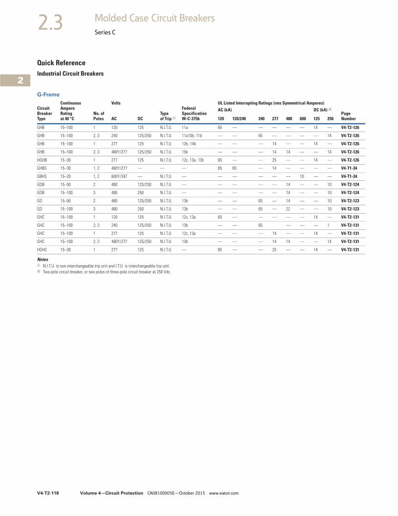
Quick ReferenceIndustrial Circuit Breakers
G-Frame
Notes1 N.I.T.U. is non-interchangeable trip unit and I.T.U. is interchangeable trip unit.2 Two-pole circuit breaker, or two poles of three-pole circuit breaker at 250 Vdc.
CircuitBreakerType
ContinuousAmpereRatingat 40 °C
No. ofPoles
Volts
Type of Trip 1
Federal Specification W-C-375b
UL Listed Interrupting Ratings (rms Symmetrical Amperes)
PageNumberAC DC
AC (kA) DC (kA) 2
120 120/240 240 277 480 600 125 250
GHB 15–100 1 120 125 N.I.T.U. 11a 65 — — — — — 14 — V4-T2-126
GHB 15–100 2, 3 240 125/250 N.I.T.U. 11a10b, 11b — — 65 — — — — 14 V4-T2-126
GHB 15–100 1 277 125 N.I.T.U. 12b, 14b — — — 14 — — 14 — V4-T2-126
GHB 15–100 2, 3 480Y/277 125/250 N.I.T.U. 15b — — — 14 14 — — 14 V4-T2-126
HGHB 15–30 1 277 125 N.I.T.U. 12c, 13a, 13b 65 — — 25 — — 14 — V4-T2-126
GHBS 15–30 1, 2 480Y/277 — — — 65 65 — 14 — — — — V4-T1-34
GBHS 15–20 1, 2 600Y/347 — N.I.T.U. — — — — — — 10 — — V4-T1-34
GDB 15–50 2 480 125/250 N.I.T.U. — — — — — 14 — — 10 V4-T2-124
GDB 15–100 3 480 250 N.I.T.U. — — — — — 14 — — 10 V4-T2-124
GD 15–50 2 480 125/250 N.I.T.U. 13b — — 65 — 14 — — 10 V4-T2-123
GD 15–100 3 480 250 N.I.T.U. 13b — — 65 — 22 — — 10 V4-T2-123
GHC 15–100 1 120 125 N.I.T.U. 12c, 13a 65 — — — — — 14 — V4-T2-131
GHC 15–100 2, 3 240 125/250 N.I.T.U. 13b — — 65 — — — 1 V4-T2-131
GHC 15–100 1 277 125 N.I.T.U. 12c, 13a — — — 14 — — 14 — V4-T2-131
GHC 15–100 2, 3 480Y/277 125/250 N.I.T.U. 13b — — — 14 14 — — 14 V4-T2-131
HGHC 15–30 1 277 125 N.I.T.U. — 65 — — 25 — — 14 — V4-T2-131
Volume 4—Circuit Protection CA08100005E—October 2015 www.eaton.com V4-T2-119
2
2
2
2
2
2
2
2
2
2
2
2
2
2
2
2
2
2
2
2
2
2
2
2
2
2
2
2
2
2
2.3Molded Case Circuit Breakers
Series C
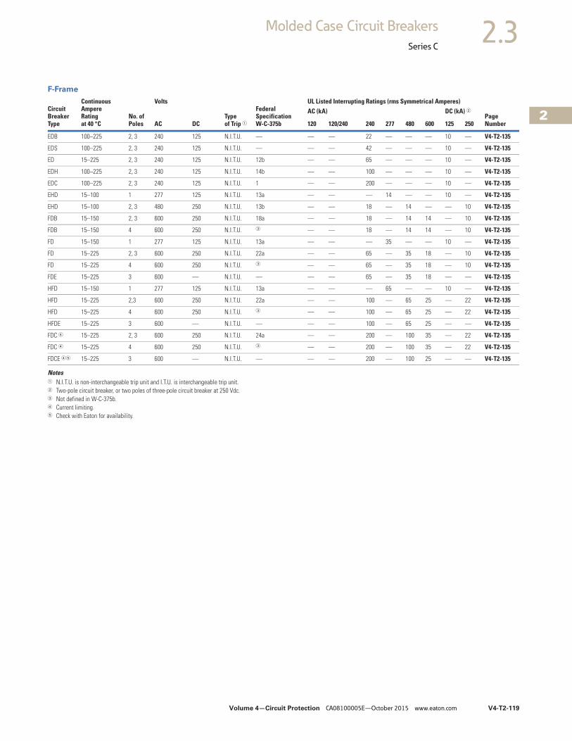
F-Frame
Notes1 N.I.T.U. is non-interchangeable trip unit and I.T.U. is interchangeable trip unit.2 Two-pole circuit breaker, or two poles of three-pole circuit breaker at 250 Vdc.3 Not defined in W-C-375b.4 Current limiting.5 Check with Eaton for availability.
CircuitBreakerType
ContinuousAmpereRatingat 40 °C
No. ofPoles
Volts
Type of Trip 1
Federal Specification W-C-375b
UL Listed Interrupting Ratings (rms Symmetrical Amperes)
PageNumberAC DC
AC (kA) DC (kA) 2
120 120/240 240 277 480 600 125 250
EDB 100–225 2, 3 240 125 N.I.T.U. — — — 22 — — — 10 — V4-T2-135
EDS 100–225 2, 3 240 125 N.I.T.U. — — — 42 — — — 10 — V4-T2-135
ED 15–225 2, 3 240 125 N.I.T.U. 12b — — 65 — — — 10 — V4-T2-135
EDH 100–225 2, 3 240 125 N.I.T.U. 14b — — 100 — — — 10 — V4-T2-135
EDC 100–225 2, 3 240 125 N.I.T.U. 1 — — 200 — — — 10 — V4-T2-135
EHD 15–100 1 277 125 N.I.T.U. 13a — — — 14 — — 10 — V4-T2-135
EHD 15–100 2, 3 480 250 N.I.T.U. 13b — — 18 — 14 — — 10 V4-T2-135
FDB 15–150 2, 3 600 250 N.I.T.U. 18a — — 18 — 14 14 — 10 V4-T2-135
FDB 15–150 4 600 250 N.I.T.U. 3 — — 18 — 14 14 — 10 V4-T2-135
FD 15–150 1 277 125 N.I.T.U. 13a — — — 35 — — 10 — V4-T2-135
FD 15–225 2, 3 600 250 N.I.T.U. 22a — — 65 — 35 18 — 10 V4-T2-135
FD 15–225 4 600 250 N.I.T.U. 3 — — 65 — 35 18 — 10 V4-T2-135
FDE 15–225 3 600 — N.I.T.U. — — — 65 — 35 18 — — V4-T2-135
HFD 15–150 1 277 125 N.I.T.U. 13a — — — 65 — — 10 — V4-T2-135
HFD 15–225 2,3 600 250 N.I.T.U. 22a — — 100 — 65 25 — 22 V4-T2-135
HFD 15–225 4 600 250 N.I.T.U. 3 — — 100 — 65 25 — 22 V4-T2-135
HFDE 15–225 3 600 — N.I.T.U. — — — 100 — 65 25 — — V4-T2-135
FDC 4 15–225 2, 3 600 250 N.I.T.U. 24a — — 200 — 100 35 — 22 V4-T2-135
FDC 4 15–225 4 600 250 N.I.T.U. 3 — — 200 — 100 35 — 22 V4-T2-135
FDCE 45 15–225 3 600 — N.I.T.U. — — — 200 — 100 25 — — V4-T2-135
V4-T2-120 Volume 4—Circuit Protection CA08100005E—October 2015 www.eaton.com
2
2
2
2
2
2
2
2
2
2
2
2
2
2
2
2
2
2
2
2
2
2
2
2
2
2
2
2
2
2
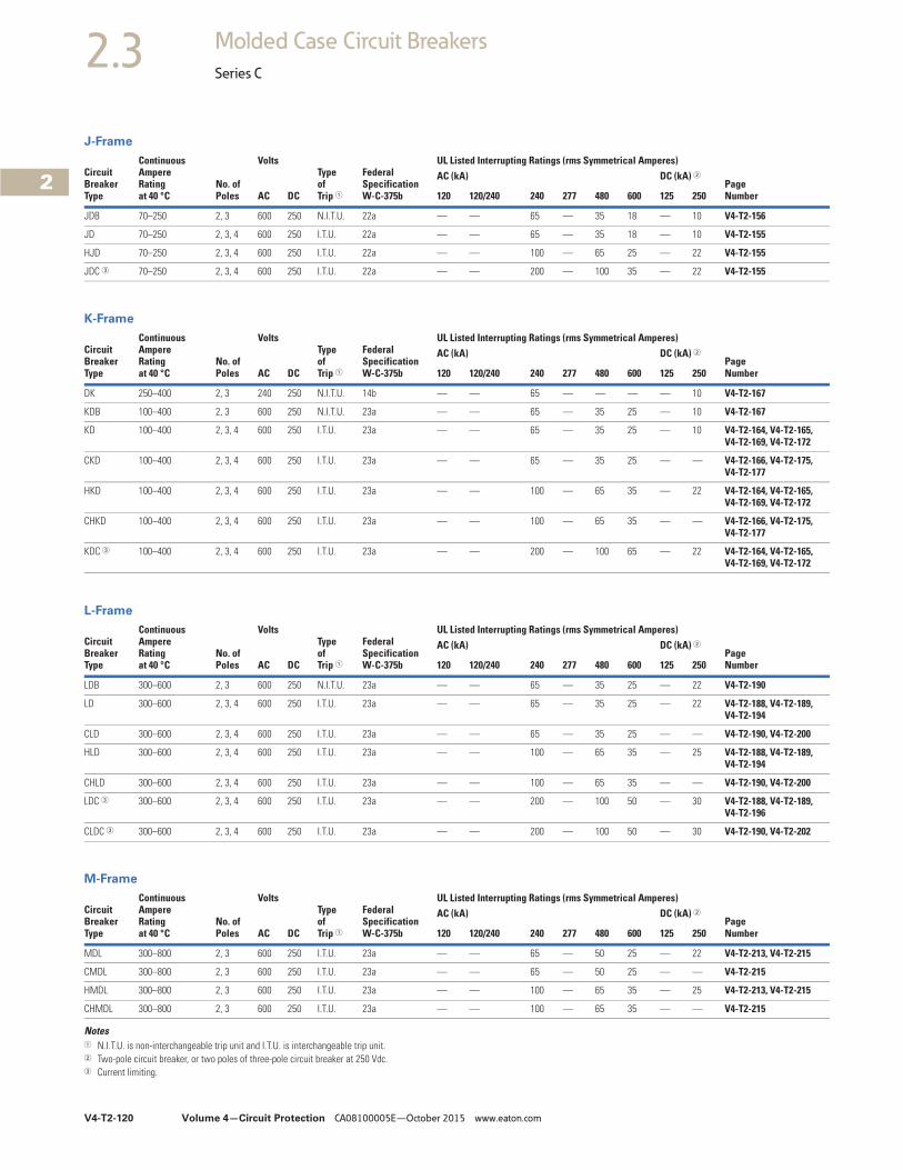
2.3 Molded Case Circuit Breakers
Series C
J-Frame
K-Frame
L-Frame
M-Frame
Notes1 N.I.T.U. is non-interchangeable trip unit and I.T.U. is interchangeable trip unit.2 Two-pole circuit breaker, or two poles of three-pole circuit breaker at 250 Vdc.3 Current limiting.
CircuitBreakerType
ContinuousAmpereRatingat 40 °C
No. ofPoles
VoltsType of Trip 1
Federal SpecificationW-C-375b
UL Listed Interrupting Ratings (rms Symmetrical Amperes)
PageNumberAC DC
AC (kA) DC (kA) 2
120 120/240 240 277 480 600 125 250
JDB 70–250 2, 3 600 250 N.I.T.U. 22a — — 65 — 35 18 — 10 V4-T2-156
JD 70–250 2, 3, 4 600 250 I.T.U. 22a — — 65 — 35 18 — 10 V4-T2-155
HJD 70–250 2, 3, 4 600 250 I.T.U. 22a — — 100 — 65 25 — 22 V4-T2-155
JDC 3 70–250 2, 3, 4 600 250 I.T.U. 22a — — 200 — 100 35 — 22 V4-T2-155
CircuitBreakerType
ContinuousAmpereRatingat 40 °C
No. ofPoles
VoltsType of Trip 1
Federal SpecificationW-C-375b
UL Listed Interrupting Ratings (rms Symmetrical Amperes)
PageNumberAC DC
AC (kA) DC (kA) 2
120 120/240 240 277 480 600 125 250
DK 250–400 2, 3 240 250 N.I.T.U. 14b — — 65 — — — — 10 V4-T2-167
KDB 100–400 2, 3 600 250 N.I.T.U. 23a — — 65 — 35 25 — 10 V4-T2-167
KD 100–400 2, 3, 4 600 250 I.T.U. 23a — — 65 — 35 25 — 10 V4-T2-164, V4-T2-165, V4-T2-169, V4-T2-172
CKD 100–400 2, 3, 4 600 250 I.T.U. 23a — — 65 — 35 25 — — V4-T2-166, V4-T2-175, V4-T2-177
HKD 100–400 2, 3, 4 600 250 I.T.U. 23a — — 100 — 65 35 — 22 V4-T2-164, V4-T2-165, V4-T2-169, V4-T2-172
CHKD 100–400 2, 3, 4 600 250 I.T.U. 23a — — 100 — 65 35 — — V4-T2-166, V4-T2-175, V4-T2-177
KDC 3 100–400 2, 3, 4 600 250 I.T.U. 23a — — 200 — 100 65 — 22 V4-T2-164, V4-T2-165, V4-T2-169, V4-T2-172
CircuitBreakerType
ContinuousAmpereRatingat 40 °C
No. ofPoles
VoltsType of Trip 1
Federal SpecificationW-C-375b
UL Listed Interrupting Ratings (rms Symmetrical Amperes)
PageNumberAC DC
AC (kA) DC (kA) 2
120 120/240 240 277 480 600 125 250
LDB 300–600 2, 3 600 250 N.I.T.U. 23a — — 65 — 35 25 — 22 V4-T2-190
LD 300–600 2, 3, 4 600 250 I.T.U. 23a — — 65 — 35 25 — 22 V4-T2-188, V4-T2-189, V4-T2-194
CLD 300–600 2, 3, 4 600 250 I.T.U. 23a — — 65 — 35 25 — — V4-T2-190, V4-T2-200
HLD 300–600 2, 3, 4 600 250 I.T.U. 23a — — 100 — 65 35 — 25 V4-T2-188, V4-T2-189, V4-T2-194
CHLD 300–600 2, 3, 4 600 250 I.T.U. 23a — — 100 — 65 35 — — V4-T2-190, V4-T2-200
LDC 3 300–600 2, 3, 4 600 250 I.T.U. 23a — — 200 — 100 50 — 30 V4-T2-188, V4-T2-189, V4-T2-196
CLDC 3 300–600 2, 3, 4 600 250 I.T.U. 23a — — 200 — 100 50 — 30 V4-T2-190, V4-T2-202
CircuitBreakerType
ContinuousAmpereRatingat 40 °C
No. ofPoles
VoltsType of Trip 1
Federal SpecificationW-C-375b
UL Listed Interrupting Ratings (rms Symmetrical Amperes)
PageNumberAC DC
AC (kA) DC (kA) 2
120 120/240 240 277 480 600 125 250
MDL 300–800 2, 3 600 250 I.T.U. 23a — — 65 — 50 25 — 22 V4-T2-213, V4-T2-215
CMDL 300–800 2, 3 600 250 I.T.U. 23a — — 65 — 50 25 — — V4-T2-215
HMDL 300–800 2, 3 600 250 I.T.U. 23a — — 100 — 65 35 — 25 V4-T2-213, V4-T2-215
CHMDL 300–800 2, 3 600 250 I.T.U. 23a — — 100 — 65 35 — — V4-T2-215

Volume 4—Circuit Protection CA08100005E—October 2015 www.eaton.com V4-T2-121
2
2
2
2
2
2
2
2
2
2
2
2
2
2
2
2
2
2
2
2
2
2
2
2
2
2
2
2
2
2
2.3Molded Case Circuit Breakers
Series C
Molded Case Circuit Breaker Product Family ContentsDescription Page
Product Overview . . . . . . . . . . . . . . . . . . . . . . . . . . V4-T2-116Standards and Certifications . . . . . . . . . . . . . . . . . . V4-T2-117Quick Reference . . . . . . . . . . . . . . . . . . . . . . . . . . . V4-T2-118G-Frame (15–100 Amperes)
Catalog Number Selection . . . . . . . . . . . . . . . . . V4-T2-122Technical Data and Specifications. . . . . . . . . . . . V4-T2-122
F-Frame (10–225 Amperes) . . . . . . . . . . . . . . . . . . . V4-T2-135J-Frame (70–250 Amperes) . . . . . . . . . . . . . . . . . . . V4-T2-153K-Frame (70–400 Amperes) . . . . . . . . . . . . . . . . . . . V4-T2-161L-Frame (125–600 Amperes) . . . . . . . . . . . . . . . . . . V4-T2-185M-Frame (300–800 Amperes) . . . . . . . . . . . . . . . . . V4-T2-211N-Frame (400–1200 Amperes). . . . . . . . . . . . . . . . . V4-T2-222R-Frame (800–2500 Amperes) . . . . . . . . . . . . . . . . . V4-T2-237Motor Circuit Protectors (MCP) . . . . . . . . . . . . . . . . V4-T2-256Motor Protection Circuit Breakers (MPCB) . . . . . . . V4-T2-267Type ELC Current Limiter Attachment (Size 0–4) . . . . . V4-T2-269Current Limiting Circuit Breaker Module. . . . . . . . . . . V4-T2-270Internal Accessories. . . . . . . . . . . . . . . . . . . . . . . . . V4-T2-273External Accessories . . . . . . . . . . . . . . . . . . . . . . . . V4-T2-304
G-Frame (15–100 Amperes)Product Description● All two- and three-pole
circuit breakers are of the common trip type. On all three-phase delta (240 V) Grounded B phase applications, refer to Eaton
● Single-pole circuit breakers, 15 and 20 amperes. Switching duty rated (SWD) for fluorescent lighting applications
● All G-Frame circuit breakers are suitable for reverse feed use
● HACR rated
V4-T2-122 Volume 4—Circuit Protection CA08100005E—October 2015 www.eaton.com
2
2
2
2
2
2
2
2
2
2
2
2
2
2
2
2
2
2
2
2
2
2
2
2
2
2
2
2
2
2
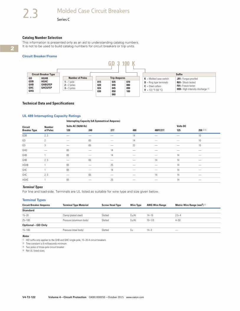
2.3 Molded Case Circuit Breakers
Series C
Catalog Number SelectionThis information is presented only as an aid to understanding catalog numbers. It is not to be used to build catalog numbers for circuit breakers or trip units.
Circuit Breaker/Frame
Technical Data and Specifications
UL 489 Interrupting Capacity Ratings
Terminal TypesFor line and load-side. Terminals are UL listed as suitable for wire type and size given below.
Terminal Types
Notes1 HID suffix only applies to the GHB and GHC single-pole, 15–20 A circuit breakers.2 Time constant is 8 milliseconds minimum.3 Two poles of three-pole circuit breaker.4 Not UL listed sizes.
Circuit Breaker Type
Number of Poles
Interrupting Capacity (kA Symmetrical Amperes)
Volts AC (50/60 Hz) Volts DC120 240 277 480 480Y/277 125 250 23
GDB 2, 3 — — — 14 — — 10
GD 2 — 65 — 14 — — 10
GD 3 — 65 — 22 — — 10
GHQ — 65 — 14 — — — —
GHB 1 65 — 14 — — 14 —
GHB 2, 3 — 65 — — 14 14 —
HGHB 1 65 — 25 — — 14 —
GHC 1 65 — 14 — — 14 —
GHC 2, 3 — 65 — — 14 14 —
HGHC 1 65 — 25 — — 14 —
Number of Poles1 = 1 pole2 = 2 poles3 = 3 poles
Circuit Breaker TypeGDGDBGHBGHCGHQ
HGHBHGHCGHBGFEPGHCGFEP
Suffix
K = Molded case switchD = Ring type terminalsC = Steel collarsV = 122 °F (50 °C)
J01= Fungus proofedR01= Shock testedF01= Freeze testerHID= High intensity discharge 1
Trip Amperes015020024030
035040045050060
070080090100
GD 3 100 K
Circuit Breaker Amperes Terminal Type Material Screw Head Type Wire Type AWG Wire Range Metric Wire Range (mm2) 4
Standard
15–20 Clamp (plated steel) Slotted Cu/Al 14–10 2.5–4
25–100 Pressure (aluminum body) Slotted Cu/Al 10–1/0 4–50
Optional—GD Only
15–100 Pressure (steel body) Slotted Cu 14–3 —

Volume 4—Circuit Protection CA08100005E—October 2015 www.eaton.com V4-T2-123
2
2
2
2
2
2
2
2
2
2
2
2
2
2
2
2
2
2
2
2
2
2
2
2
2
2
2
2
2
2
2.3Molded Case Circuit Breakers
Series C
Typical G-Frame Circuit Breaker ContentsDescription Page
Product Overview . . . . . . . . . . . . . . . . . . . . . . . . . . V4-T2-116Standards and Certifications . . . . . . . . . . . . . . . . . . V4-T2-117Quick Reference. . . . . . . . . . . . . . . . . . . . . . . . . . . . V4-T2-118G-Frame (15–100 Amperes) . . . . . . . . . . . . . . . . . . . V4-T2-121F-Frame (10–225 Amperes) . . . . . . . . . . . . . . . . . . . V4-T2-135J-Frame (70–250 Amperes) . . . . . . . . . . . . . . . . . . . V4-T2-153K-Frame (70–400 Amperes) . . . . . . . . . . . . . . . . . . . V4-T2-161L-Frame (125–600 Amperes) . . . . . . . . . . . . . . . . . . V4-T2-185M-Frame (300–800 Amperes) . . . . . . . . . . . . . . . . . V4-T2-211N-Frame (400–1200 Amperes). . . . . . . . . . . . . . . . . V4-T2-222R-Frame (800–2500 Amperes) . . . . . . . . . . . . . . . . . V4-T2-237Motor Circuit Protectors (MCP) . . . . . . . . . . . . . . . . V4-T2-256Motor Protection Circuit Breakers (MPCB) . . . . . . . V4-T2-267Type ELC Current Limiter Attachment (Size 0–4) . . . . . V4-T2-269Current Limiting Circuit Breaker Module. . . . . . . . . . . V4-T2-270Internal Accessories. . . . . . . . . . . . . . . . . . . . . . . . . V4-T2-273External Accessories . . . . . . . . . . . . . . . . . . . . . . . . V4-T2-304
Type GD Thermal-Magnetic Circuit Breakers with Non-Interchangeable Trip Units (15–100 Amperes)Product Description● Cable in, cable out● Includes mounting
hardware and BMHE
Standards and Certifications● UL/CSA
Product Selection
Type GD Thermal-Magnetic Circuit Breakers with Non-Interchangeable Trip Units
MaximumContinuousAmpere Ratingat 40 °C
480 Vac Maximum, 250 VdcIncludes BindingHead Screws and Clamps10–32 x 0.312
14 kAIC at 480 Vac 22 kAIC at 480 VacIncludes Line and Load TerminalsTwo-Pole Three-Pole Three-PoleCatalogNumber
CatalogNumber
CatalogNumber
15 GD2015 GD3015 GD3015D
20 GD2020 GD3020 GD3020D
25 GD2025 GD3025 GD3025D
30 GD2030 GD3030 GD3030D
35 GD2035 GD3035 GD3035D
40 GD2040 GD3040 GD3040D
45 GD2045 GD3045 GD3045D
50 GD2050 GD3050 GD3050D
60 — GD3060 GD3060D
70 — GD3070 GD3070D
80 — GD3080 GD3080D
90 — GD3090 GD3090D
100 — GD3100 GD3100D

V4-T2-124 Volume 4—Circuit Protection CA08100005E—October 2015 www.eaton.com
2
2
2
2
2
2
2
2
2
2
2
2
2
2
2
2
2
2
2
2
2
2
2
2
2
2
2
2
2
2
2.3 Molded Case Circuit Breakers
Series C
Type GDB Thermal-Magnetic Circuit Breakers with Non-Interchangeable Trip Units
Type GD Molded Case Switches
Type GD Molded Case Switches—Three-Pole
Notes1 Includes line and load steel terminals.2 Includes binding head screws and clamps 10–32 x 0.312.
Molded case switches may open above 1300 amperes.
MaximumContinuousAmpere Ratingat 40 °C
480 Vac Maximum, 250 Vdc14 kAIC at 480 VacIncludes Line and Load TerminalsTwo-Pole Three-PoleCatalogNumber
CatalogNumber
15 GDB2015 GDB3015
20 GDB2020 GDB3020
25 GDB2025 GDB3025
30 GDB2030 GDB3030
35 GDB2035 GDB3035
40 GDB2040 GDB3040
45 GDB2045 GDB3045
50 GDB2050 GDB3050
60 — GDB3060
70 — GDB3070
80 — GDB3080
90 — GDB3090
100 — GDB3100
Maximum Continuous Ampere Rating at 40 °C
480 Vac Maximum, 250 VdcCatalog Number (Includes Line and Load Terminals)
60 GD3060K
60 GD3060KC 1
100 GD3100K
100 GD3100KD 2

Volume 4—Circuit Protection CA08100005E—October 2015 www.eaton.com V4-T2-125
2
2
2
2
2
2
2
2
2
2
2
2
2
2
2
2
2
2
2
2
2
2
2
2
2
2
2
2
2
2
2.3Molded Case Circuit Breakers
Series C
DimensionsApproximate Dimensions in Inches (mm)
GD-Frame, Three-Pole
Off
3.00
(76.2)
4.88
(123.8)
2.63
(66.7)
Front View Side View
V4-T2-126 Volume 4—Circuit Protection CA08100005E—October 2015 www.eaton.com
2
2
2
2
2
2
2
2
2
2
2
2
2
2
2
2
2
2
2
2
2
2
2
2
2
2
2
2
2
2
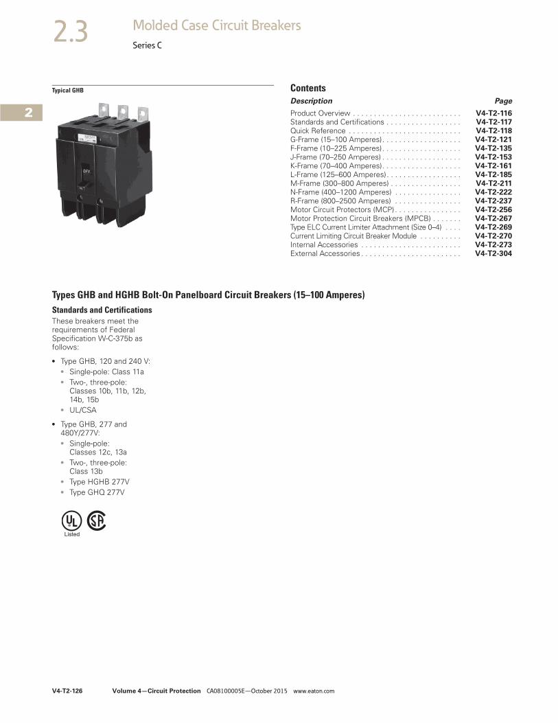
2.3 Molded Case Circuit Breakers
Series C
Typical GHB ContentsDescription Page
Product Overview . . . . . . . . . . . . . . . . . . . . . . . . . . V4-T2-116Standards and Certifications . . . . . . . . . . . . . . . . . . V4-T2-117Quick Reference . . . . . . . . . . . . . . . . . . . . . . . . . . . V4-T2-118G-Frame (15–100 Amperes). . . . . . . . . . . . . . . . . . . V4-T2-121F-Frame (10–225 Amperes). . . . . . . . . . . . . . . . . . . V4-T2-135J-Frame (70–250 Amperes) . . . . . . . . . . . . . . . . . . . V4-T2-153K-Frame (70–400 Amperes). . . . . . . . . . . . . . . . . . . V4-T2-161L-Frame (125–600 Amperes). . . . . . . . . . . . . . . . . . V4-T2-185M-Frame (300–800 Amperes) . . . . . . . . . . . . . . . . . V4-T2-211N-Frame (400–1200 Amperes) . . . . . . . . . . . . . . . . V4-T2-222R-Frame (800–2500 Amperes) . . . . . . . . . . . . . . . . V4-T2-237Motor Circuit Protectors (MCP) . . . . . . . . . . . . . . . . V4-T2-256Motor Protection Circuit Breakers (MPCB) . . . . . . . V4-T2-267Type ELC Current Limiter Attachment (Size 0–4) . . . . V4-T2-269Current Limiting Circuit Breaker Module . . . . . . . . . . V4-T2-270Internal Accessories . . . . . . . . . . . . . . . . . . . . . . . . V4-T2-273External Accessories . . . . . . . . . . . . . . . . . . . . . . . . V4-T2-304
Types GHB and HGHB Bolt-On Panelboard Circuit Breakers (15–100 Amperes)Standards and CertificationsThese breakers meet the requirements of Federal Specification W-C-375b as follows:
● Type GHB, 120 and 240 V:● Single-pole: Class 11a● Two-, three-pole:
Classes 10b, 11b, 12b, 14b, 15b
● UL/CSA
● Type GHB, 277 and 480Y/277V:● Single-pole:
Classes 12c, 13a● Two-, three-pole:
Class 13b● Type HGHB 277V● Type GHQ 277V
Volume 4—Circuit Protection CA08100005E—October 2015 www.eaton.com V4-T2-127
2
2
2
2
2
2
2
2
2
2
2
2
2
2
2
2
2
2
2
2
2
2
2
2
2
2
2
2
2
2
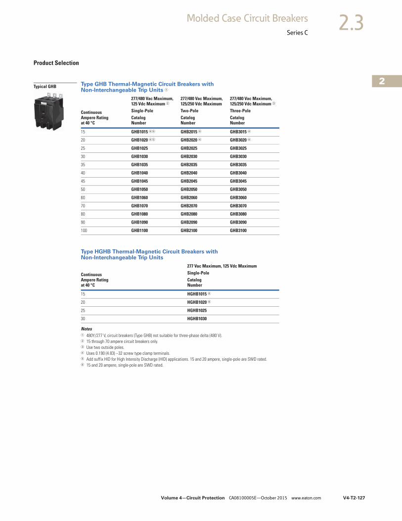
2.3Molded Case Circuit Breakers
Series C
Product Selection
Type GHB Thermal-Magnetic Circuit Breakers with Non-Interchangeable Trip Units 1
Type HGHB Thermal-Magnetic Circuit Breakers with Non-Interchangeable Trip Units
Notes1 480Y/277 V, circuit breakers (Type GHB) not suitable for three-phase delta (480 V).2 15 through 70 ampere circuit breakers only.3 Use two outside poles.4 Uses 0.190 (4.83) –32 screw type clamp terminals.5 Add suffix HID for High Intensity Discharge (HID) applications. 15 and 20 ampere, single-pole are SWD rated.6 15 and 20 ampere, single-pole are SWD rated.
Continuous Ampere Ratingat 40 °C
277/480 Vac Maximum, 125 Vdc Maximum 2
277/480 Vac Maximum, 125/250 Vdc Maximum
277/480 Vac Maximum, 125/250 Vdc Maximum 3
Single-Pole Two-Pole Three-PoleCatalogNumber
CatalogNumber
CatalogNumber
15 GHB1015 45 GHB2015 4 GHB3015 4
20 GHB1020 45 GHB2020 4 GHB3020 4
25 GHB1025 GHB2025 GHB3025
30 GHB1030 GHB2030 GHB3030
35 GHB1035 GHB2035 GHB3035
40 GHB1040 GHB2040 GHB3040
45 GHB1045 GHB2045 GHB3045
50 GHB1050 GHB2050 GHB3050
60 GHB1060 GHB2060 GHB3060
70 GHB1070 GHB2070 GHB3070
80 GHB1080 GHB2080 GHB3080
90 GHB1090 GHB2090 GHB3090
100 GHB1100 GHB2100 GHB3100
Continuous Ampere Rating at 40 °C
277 Vac Maximum, 125 Vdc MaximumSingle-PoleCatalog Number
15 HGHB1015 6
20 HGHB1020 6
25 HGHB1025
30 HGHB1030
Typical GHB
V4-T2-128 Volume 4—Circuit Protection CA08100005E—October 2015 www.eaton.com
2
2
2
2
2
2
2
2
2
2
2
2
2
2
2
2
2
2
2
2
2
2
2
2
2
2
2
2
2
2
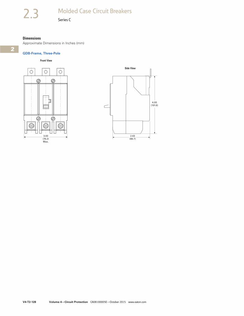
2.3 Molded Case Circuit Breakers
Series C
DimensionsApproximate Dimensions in Inches (mm)
GDB-Frame, Three-Pole
3.00
(76.2)
Max.
2.63
(66.7)
4.00
(101.6)
Front View
Side View
Volume 4—Circuit Protection CA08100005E—October 2015 www.eaton.com V4-T2-129
2
2
2
2
2
2
2
2
2
2
2
2
2
2
2
2
2
2
2
2
2
2
2
2
2
2
2
2
2
2
2.3Molded Case Circuit Breakers
Series C
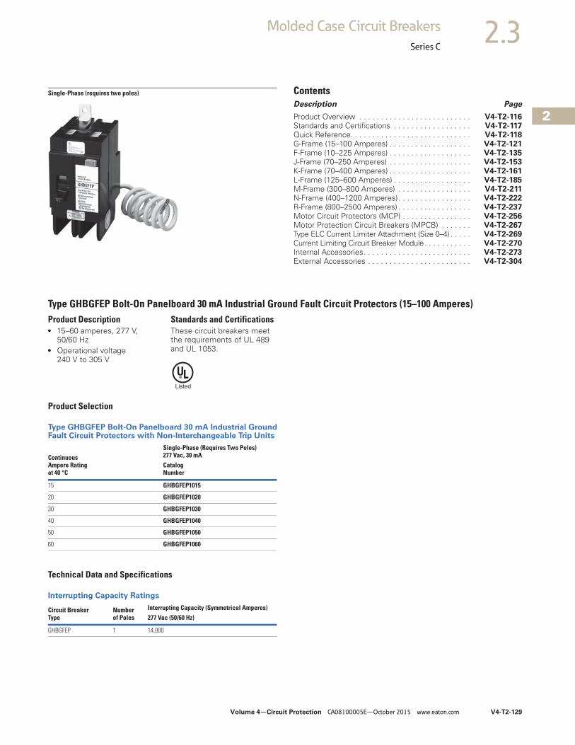
Single-Phase (requires two poles) ContentsDescription Page
Product Overview . . . . . . . . . . . . . . . . . . . . . . . . . . V4-T2-116Standards and Certifications . . . . . . . . . . . . . . . . . . V4-T2-117Quick Reference. . . . . . . . . . . . . . . . . . . . . . . . . . . . V4-T2-118G-Frame (15–100 Amperes) . . . . . . . . . . . . . . . . . . . V4-T2-121F-Frame (10–225 Amperes) . . . . . . . . . . . . . . . . . . . V4-T2-135J-Frame (70–250 Amperes) . . . . . . . . . . . . . . . . . . . V4-T2-153K-Frame (70–400 Amperes) . . . . . . . . . . . . . . . . . . . V4-T2-161L-Frame (125–600 Amperes) . . . . . . . . . . . . . . . . . . V4-T2-185M-Frame (300–800 Amperes) . . . . . . . . . . . . . . . . . V4-T2-211N-Frame (400–1200 Amperes). . . . . . . . . . . . . . . . . V4-T2-222R-Frame (800–2500 Amperes) . . . . . . . . . . . . . . . . . V4-T2-237Motor Circuit Protectors (MCP) . . . . . . . . . . . . . . . . V4-T2-256Motor Protection Circuit Breakers (MPCB) . . . . . . . V4-T2-267Type ELC Current Limiter Attachment (Size 0–4) . . . . . V4-T2-269Current Limiting Circuit Breaker Module. . . . . . . . . . . V4-T2-270Internal Accessories. . . . . . . . . . . . . . . . . . . . . . . . . V4-T2-273External Accessories . . . . . . . . . . . . . . . . . . . . . . . . V4-T2-304
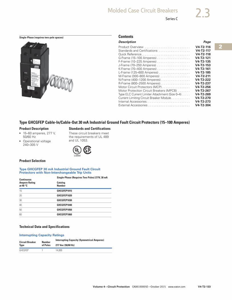
Type GHBGFEP Bolt-On Panelboard 30 mA Industrial Ground Fault Circuit Protectors (15–100 Amperes)Product Description● 15–60 amperes, 277 V,
50/60 Hz● Operational voltage
240 V to 305 V
Standards and CertificationsThese circuit breakers meet the requirements of UL 489 and UL 1053.
Product Selection
Type GHBGFEP Bolt-On Panelboard 30 mA Industrial Ground Fault Circuit Protectors with Non-Interchangeable Trip Units
Technical Data and Specifications
Interrupting Capacity Ratings
Continuous Ampere Ratingat 40 °C
Single-Phase (Requires Two Poles)277 Vac, 30 mACatalogNumber
15 GHBGFEP1015
20 GHBGFEP1020
30 GHBGFEP1030
40 GHBGFEP1040
50 GHBGFEP1050
60 GHBGFEP1060
Circuit Breaker Type
Number of Poles
Interrupting Capacity (Symmetrical Amperes)277 Vac (50/60 Hz)
GHBGFEP 1 14,000
V4-T2-130 Volume 4—Circuit Protection CA08100005E—October 2015 www.eaton.com
2
2
2
2
2
2
2
2
2
2
2
2
2
2
2
2
2
2
2
2
2
2
2
2
2
2
2
2
2
2
2.3 Molded Case Circuit Breakers
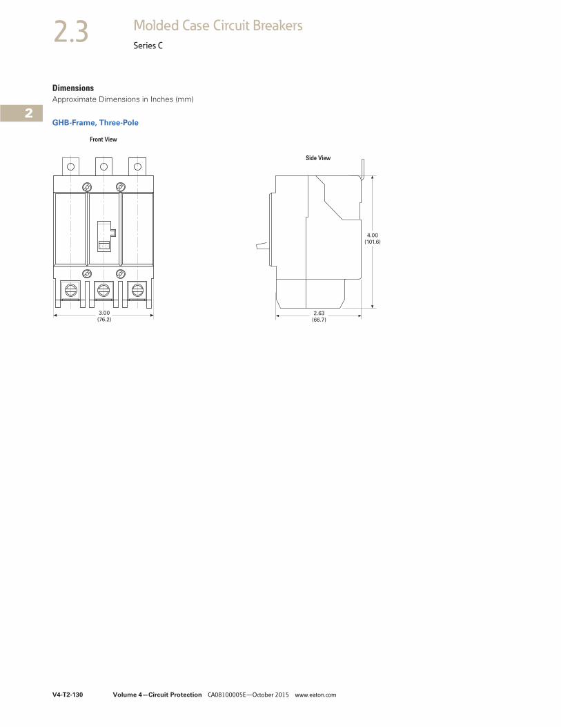
Series C
DimensionsApproximate Dimensions in Inches (mm)
GHB-Frame, Three-Pole
3.00
(76.2)2.63
(66.7)
4.00
(101.6)
Front View
Side View
Volume 4—Circuit Protection CA08100005E—October 2015 www.eaton.com V4-T2-131
2
2
2
2
2
2
2
2
2
2
2
2
2
2
2
2
2
2
2
2
2
2
2
2
2
2
2
2
2
2
2.3Molded Case Circuit Breakers
Series C
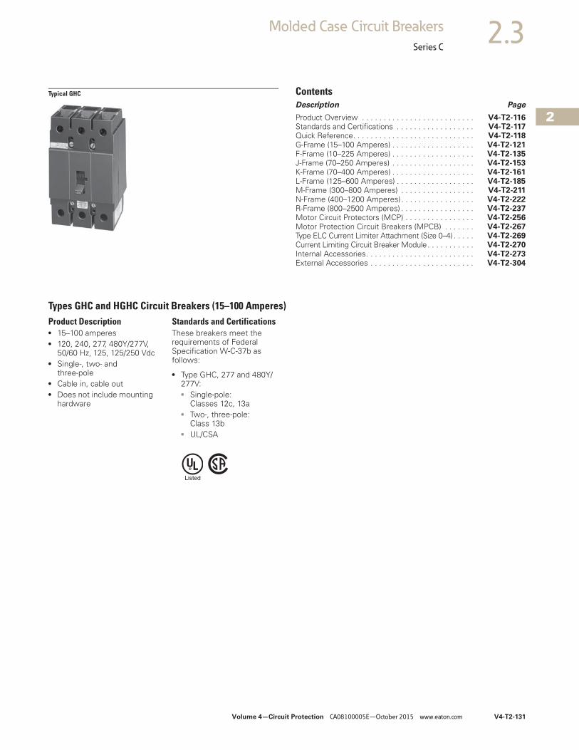
Typical GHC ContentsDescription Page
Product Overview . . . . . . . . . . . . . . . . . . . . . . . . . . V4-T2-116Standards and Certifications . . . . . . . . . . . . . . . . . . V4-T2-117Quick Reference. . . . . . . . . . . . . . . . . . . . . . . . . . . . V4-T2-118G-Frame (15–100 Amperes) . . . . . . . . . . . . . . . . . . . V4-T2-121F-Frame (10–225 Amperes) . . . . . . . . . . . . . . . . . . . V4-T2-135J-Frame (70–250 Amperes) . . . . . . . . . . . . . . . . . . . V4-T2-153K-Frame (70–400 Amperes) . . . . . . . . . . . . . . . . . . . V4-T2-161L-Frame (125–600 Amperes) . . . . . . . . . . . . . . . . . . V4-T2-185M-Frame (300–800 Amperes) . . . . . . . . . . . . . . . . . V4-T2-211N-Frame (400–1200 Amperes). . . . . . . . . . . . . . . . . V4-T2-222R-Frame (800–2500 Amperes) . . . . . . . . . . . . . . . . . V4-T2-237Motor Circuit Protectors (MCP) . . . . . . . . . . . . . . . . V4-T2-256Motor Protection Circuit Breakers (MPCB) . . . . . . . V4-T2-267Type ELC Current Limiter Attachment (Size 0–4) . . . . . V4-T2-269Current Limiting Circuit Breaker Module. . . . . . . . . . . V4-T2-270Internal Accessories. . . . . . . . . . . . . . . . . . . . . . . . . V4-T2-273External Accessories . . . . . . . . . . . . . . . . . . . . . . . . V4-T2-304
Types GHC and HGHC Circuit Breakers (15–100 Amperes)Product Description● 15–100 amperes● 120, 240, 277, 480Y/277V,
50/60 Hz, 125, 125/250 Vdc● Single-, two- and
three-pole● Cable in, cable out● Does not include mounting
hardware
Standards and CertificationsThese breakers meet the requirements of Federal Specification W-C-37b as follows:
● Type GHC, 277 and 480Y/277V:● Single-pole:
Classes 12c, 13a● Two-, three-pole:
Class 13b● UL/CSA
V4-T2-132 Volume 4—Circuit Protection CA08100005E—October 2015 www.eaton.com
2
2
2
2
2
2
2
2
2
2
2
2
2
2
2
2
2
2
2
2
2
2
2
2
2
2
2
2
2
2
2.3 Molded Case Circuit Breakers
Series C
Product Selection
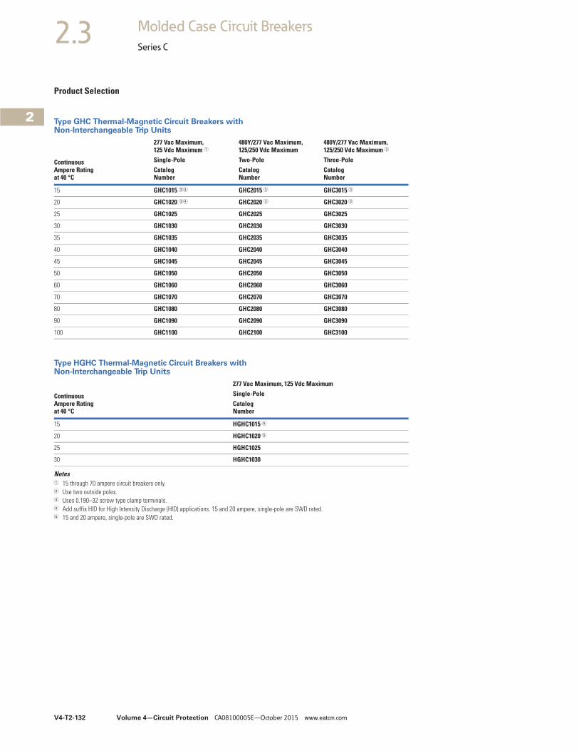
Type GHC Thermal-Magnetic Circuit Breakers with Non-Interchangeable Trip Units
Type HGHC Thermal-Magnetic Circuit Breakers with Non-Interchangeable Trip Units
Notes1 15 through 70 ampere circuit breakers only.2 Use two outside poles.3 Uses 0.190–32 screw type clamp terminals.4 Add suffix HID for High Intensity Discharge (HID) applications. 15 and 20 ampere, single-pole are SWD rated.5 15 and 20 ampere, single-pole are SWD rated.
Continuous Ampere Ratingat 40 °C
277 Vac Maximum, 125 Vdc Maximum 1
480Y/277 Vac Maximum, 125/250 Vdc Maximum
480Y/277 Vac Maximum, 125/250 Vdc Maximum 2
Single-Pole Two-Pole Three-PoleCatalogNumber
CatalogNumber
CatalogNumber
15 GHC1015 34 GHC2015 3 GHC3015 3
20 GHC1020 34 GHC2020 3 GHC3020 3
25 GHC1025 GHC2025 GHC3025
30 GHC1030 GHC2030 GHC3030
35 GHC1035 GHC2035 GHC3035
40 GHC1040 GHC2040 GHC3040
45 GHC1045 GHC2045 GHC3045
50 GHC1050 GHC2050 GHC3050
60 GHC1060 GHC2060 GHC3060
70 GHC1070 GHC2070 GHC3070
80 GHC1080 GHC2080 GHC3080
90 GHC1090 GHC2090 GHC3090
100 GHC1100 GHC2100 GHC3100
Continuous Ampere Rating at 40 °C
277 Vac Maximum, 125 Vdc MaximumSingle-PoleCatalog Number
15 HGHC1015 5
20 HGHC1020 5
25 HGHC1025
30 HGHC1030
Volume 4—Circuit Protection CA08100005E—October 2015 www.eaton.com V4-T2-133
2
2
2
2
2
2
2
2
2
2
2
2
2
2
2
2
2
2
2
2
2
2
2
2
2
2
2
2
2
2
2.3Molded Case Circuit Breakers
Series C
Single-Phase (requires two-pole spaces) ContentsDescription Page
Product Overview . . . . . . . . . . . . . . . . . . . . . . . . . . V4-T2-116Standards and Certifications . . . . . . . . . . . . . . . . . . V4-T2-117Quick Reference. . . . . . . . . . . . . . . . . . . . . . . . . . . . V4-T2-118G-Frame (15–100 Amperes) . . . . . . . . . . . . . . . . . . . V4-T2-121F-Frame (10–225 Amperes) . . . . . . . . . . . . . . . . . . . V4-T2-135J-Frame (70–250 Amperes) . . . . . . . . . . . . . . . . . . . V4-T2-153K-Frame (70–400 Amperes) . . . . . . . . . . . . . . . . . . . V4-T2-161L-Frame (125–600 Amperes) . . . . . . . . . . . . . . . . . . V4-T2-185M-Frame (300–800 Amperes) . . . . . . . . . . . . . . . . . V4-T2-211N-Frame (400–1200 Amperes). . . . . . . . . . . . . . . . . V4-T2-222R-Frame (800–2500 Amperes) . . . . . . . . . . . . . . . . . V4-T2-237Motor Circuit Protectors (MCP) . . . . . . . . . . . . . . . . V4-T2-256Motor Protection Circuit Breakers (MPCB) . . . . . . . V4-T2-267Type ELC Current Limiter Attachment (Size 0–4) . . . . . V4-T2-269Current Limiting Circuit Breaker Module. . . . . . . . . . . V4-T2-270Internal Accessories. . . . . . . . . . . . . . . . . . . . . . . . . V4-T2-273External Accessories . . . . . . . . . . . . . . . . . . . . . . . . V4-T2-304
Type GHCGFEP Cable-In/Cable-Out 30 mA Industrial Ground Fault Circuit Protectors (15–100 Amperes) Product Description● 15–60 amperes, 277 V,
50/60 Hz● Operational voltage
240–305 V
Standards and CertificationsThese circuit breakers meet the requirements of UL 489 and UL 1053.
Product Selection
Type GHCGFEP 30 mA Industrial Ground Fault Circuit Protectors with Non-Interchangeable Trip Units
Technical Data and Specifications
Interrupting Capacity Ratings
Continuous Ampere Rating at 40 °C
Single-Phase (Requires Two Poles) 277V, 30 mA
Catalog Number
15 GHCGFEP1015
20 GHCGFEP1020
30 GHCGFEP1030
40 GHCGFEP1040
50 GHCGFEP1050
60 GHCGFEP1060
Circuit Breaker Type
Number of Poles
Interrupting Capacity (Symmetrical Amperes)
277 Vac (50/60 Hz)
GHCGFEP 1 14,000
V4-T2-134 Volume 4—Circuit Protection CA08100005E—October 2015 www.eaton.com
2
2
2
2
2
2
2
2
2
2
2
2
2
2
2
2
2
2
2
2
2
2
2
2
2
2
2
2
2
2
2.3 Molded Case Circuit Breakers
Series C
Special Purpose Circuit Breakers ContentsDescription Page
Product Overview . . . . . . . . . . . . . . . . . . . . . . . . . . . V4-T2-116
Standards and Certifications. . . . . . . . . . . . . . . . . . . V4-T2-117
Quick Reference . . . . . . . . . . . . . . . . . . . . . . . . . . . . V4-T2-118
G-Frame (15–100 Amperes) . . . . . . . . . . . . . . . . . . . V4-T2-121
F-Frame (10–225 Amperes) . . . . . . . . . . . . . . . . . . . V4-T2-135
J-Frame (70–250 Amperes). . . . . . . . . . . . . . . . . . . . V4-T2-153
K-Frame (70–400 Amperes) . . . . . . . . . . . . . . . . . . . V4-T2-161
L-Frame (125–600 Amperes) . . . . . . . . . . . . . . . . . . V4-T2-185
M-Frame (300–800 Amperes). . . . . . . . . . . . . . . . . . V4-T2-211
N-Frame (400–1200 Amperes) . . . . . . . . . . . . . . . . . V4-T2-222R-Frame (800–2500 Amperes) . . . . . . . . . . . . . . . . . V4-T2-237
Motor Circuit Protectors (MCP) . . . . . . . . . . . . . . . . V4-T2-256
Motor Protection Circuit Breakers (MPCB) . . . . . . . . V4-T2-267
Type ELC Current Limiter Attachment (Size 0–4) . . . . . V4-T2-269
Current Limiting Circuit Breaker Module . . . . . . . . . . . V4-T2-270Internal Accessories . . . . . . . . . . . . . . . . . . . . . . . . . V4-T2-273External Accessories . . . . . . . . . . . . . . . . . . . . . . . . V4-T2-304
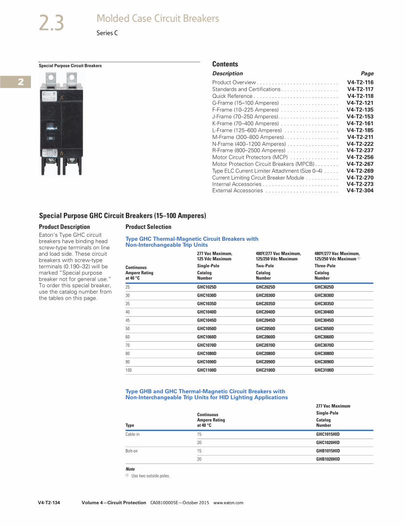
Product DescriptionEaton’s Type GHC circuit breakers have binding head screw-type terminals on line and load side. These circuit breakers with screw-type terminals (0.190–32) will be marked “Special purpose breaker not for general use.” To order this special breaker, use the catalog number from the tables on this page.
Special Purpose GHC Circuit Breakers (15–100 Amperes) Product Selection
Type GHC Thermal-Magnetic Circuit Breakers with Non-Interchangeable Trip Units
Type GHB and GHC Thermal-Magnetic Circuit Breakers with Non-Interchangeable Trip Units for HID Lighting Applications
Note1 Use two outside poles.
Continuous Ampere Ratingat 40 °C
277 Vac Maximum, 125 Vdc Maximum
480Y/277 Vac Maximum, 125/250 Vdc Maximum
480Y/277 Vac Maximum, 125/250 Vdc Maximum 1
Single-Pole Two-Pole Three-PoleCatalogNumber
CatalogNumber
CatalogNumber
25 GHC1025D GHC2025D GHC3025D
30 GHC1030D GHC2030D GHC3030D
35 GHC1035D GHC2035D GHC3035D
40 GHC1040D GHC2040D GHC3040D
45 GHC1045D GHC2045D GHC3045D
50 GHC1050D GHC2050D GHC3050D
60 GHC1060D GHC2060D GHC3060D
70 GHC1070D GHC2070D GHC3070D
80 GHC1080D GHC2080D GHC3080D
90 GHC1090D GHC2090D GHC3090D
100 GHC1100D GHC2100D GHC3100D
Type
Continuous Ampere Rating at 40 °C
277 Vac MaximumSingle-PoleCatalogNumber
Cable-in 15 GHC1015HID
20 GHC1020HID
Bolt-on 15 GHB1015HID
20 GHB1020HID
Volume 4—Circuit Protection CA08100005E—October 2015 www.eaton.com V4-T2-135
2
2
2
2
2
2
2
2
2
2
2
2
2
2
2
2
2
2
2
2
2
2
2
2
2
2
2
2
2
2
2.3Molded Case Circuit Breakers
Series C
Typical F-Frame Breaker F-Frame Breaker with Electronic Trip Unit
ContentsDescription Page
Product Overview . . . . . . . . . . . . . . . . . . . . . . . . . . V4-T2-116
Standards and Certifications . . . . . . . . . . . . . . . . . . V4-T2-117
Quick Reference . . . . . . . . . . . . . . . . . . . . . . . . . . . V4-T2-118
G-Frame (15–100 Amperes) . . . . . . . . . . . . . . . . . . . V4-T2-121
F-Frame (10–225 Amperes)Catalog Number Selection . . . . . . . . . . . . . . . . . V4-T2-136
Product Selection . . . . . . . . . . . . . . . . . . . . . . . . V4-T2-138
Accessories . . . . . . . . . . . . . . . . . . . . . . . . . . . . V4-T2-149
Technical Data and Specifications. . . . . . . . . . . . V4-T2-150
Dimensions and Weights . . . . . . . . . . . . . . . . . . V4-T2-152
J-Frame (70–250 Amperes) . . . . . . . . . . . . . . . . . . . V4-T2-153
K-Frame (70–400 Amperes) . . . . . . . . . . . . . . . . . . . V4-T2-161
L-Frame (125–600 Amperes) . . . . . . . . . . . . . . . . . . V4-T2-185
M-Frame (300–800 Amperes) . . . . . . . . . . . . . . . . . V4-T2-211
N-Frame (400–1200 Amperes). . . . . . . . . . . . . . . . . V4-T2-222R-Frame (800–2500 Amperes) . . . . . . . . . . . . . . . . . V4-T2-237
Motor Circuit Protectors (MCP) . . . . . . . . . . . . . . . . V4-T2-256
Motor Protection Circuit Breakers (MPCB) . . . . . . . V4-T2-267
Type ELC Current Limiter Attachment (Size 0–4) . . . . . V4-T2-269
Current Limiting Circuit Breaker Module. . . . . . . . . . . V4-T2-270Internal Accessories. . . . . . . . . . . . . . . . . . . . . . . . . V4-T2-273External Accessories . . . . . . . . . . . . . . . . . . . . . . . . V4-T2-304
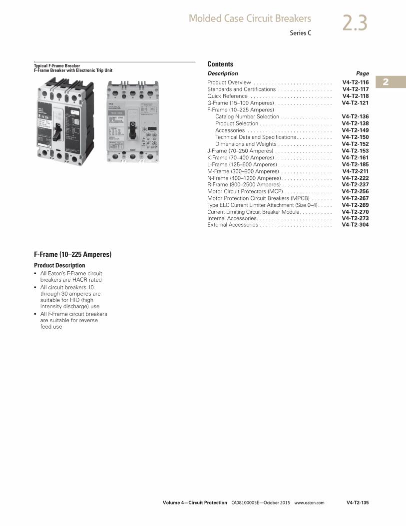
F-Frame (10–225 Amperes)Product Description● All Eaton’s F-Frame circuit
breakers are HACR rated● All circuit breakers 10
through 30 amperes are suitable for HID (high intensity discharge) use
● All F-Frame circuit breakers are suitable for reverse feed use
V4-T2-136 Volume 4—Circuit Protection CA08100005E—October 2015 www.eaton.com
2
2
2
2
2
2
2
2
2
2
2
2
2
2
2
2
2
2
2
2
2
2
2
2
2
2
2
2
2
2
2.3 Molded Case Circuit Breakers
Series C
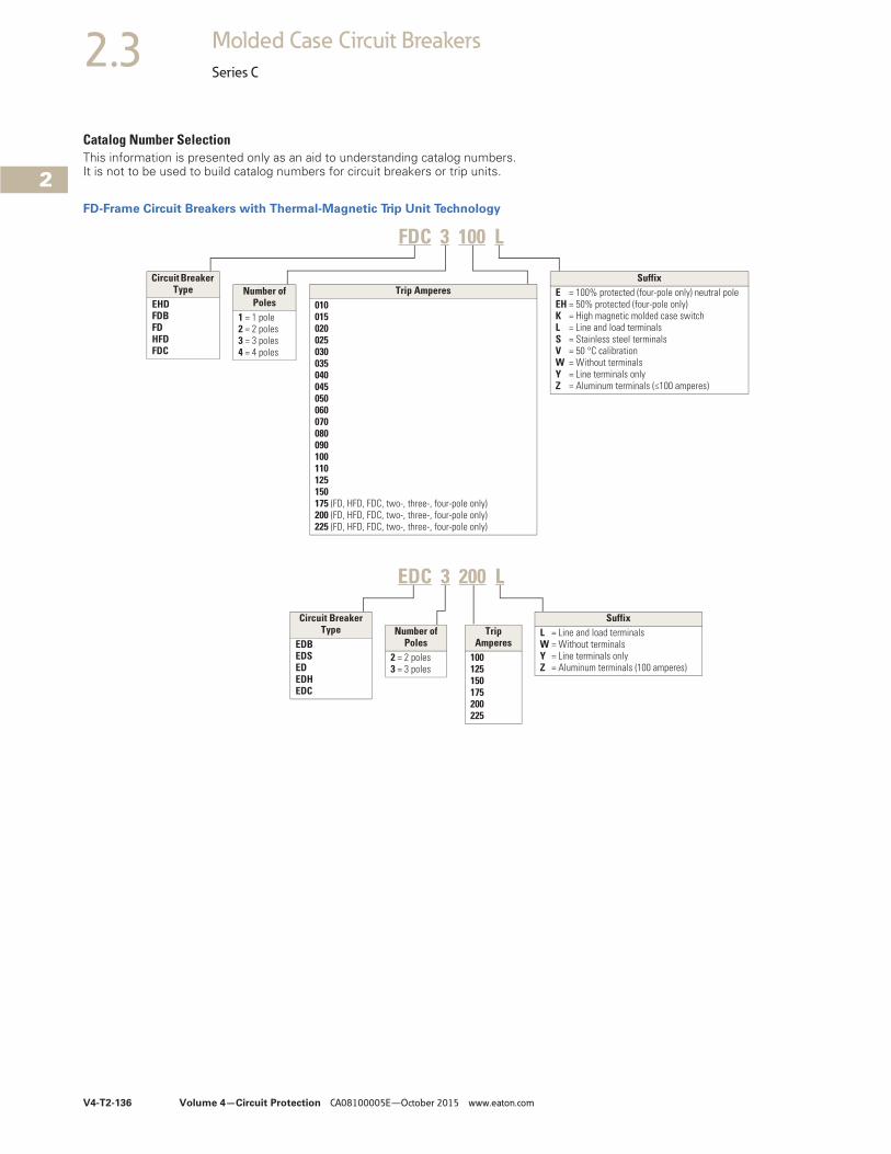
Catalog Number SelectionThis information is presented only as an aid to understanding catalog numbers. It is not to be used to build catalog numbers for circuit breakers or trip units.
FD-Frame Circuit Breakers with Thermal-Magnetic Trip Unit Technology
Trip Amperes010015020025030035040045050060070080090100110125150175 (FD, HFD, FDC, two-, three-, four-pole only)200 (FD, HFD, FDC, two-, three-, four-pole only)225 (FD, HFD, FDC, two-, three-, four-pole only)
Circuit Breaker Type
EHDFDBFDHFDFDC
Number of Poles
1 = 1 pole2 = 2 poles3 = 3 poles4 = 4 poles
SuffixE = 100% protected (four-pole only) neutral poleEH = 50% protected (four-pole only)K = High magnetic molded case switchL = Line and load terminalsS = Stainless steel terminalsV = 50 °C calibrationW = Without terminalsY = Line terminals onlyZ = Aluminum terminals (≤100 amperes)
Circuit Breaker Type
EDBEDSEDEDHEDC
Number of Poles
2 = 2 poles3 = 3 poles
Trip Amperes
100125150175200225
SuffixL = Line and load terminalsW = Without terminalsY = Line terminals onlyZ = Aluminum terminals (100 amperes)
FDC 3 100 L
EDC 3 200 L
Volume 4—Circuit Protection CA08100005E—October 2015 www.eaton.com V4-T2-137
2
2
2
2
2
2
2
2
2
2
2
2
2
2
2
2
2
2
2
2
2
2
2
2
2
2
2
2
2
2
2.3Molded Case Circuit Breakers
Series C
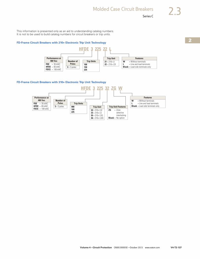
This information is presented only as an aid to understanding catalog numbers. It is not to be used to build catalog numbers for circuit breakers or trip units.
FD-Frame Circuit Breakers with 210+ Electronic Trip Unit Technology
FD-Frame Circuit Breakers with 310+ Electronic Trip Unit Technology
Performance at 480 Vac
FDE = 35 kAICHFDE = 65 kAICFDCE = 100 kAIC
Number of Poles
3 = 3 poles
Trip Unit21 = 210+ LI22 = 210+ LSI
FeaturesW = Without terminalsL = Line and load terminalsBlank = Load side terminals only
HFDE 3 225 22 L
Trip Units100 150225
Number of Poles
3 = 3 poles Trip Unit FeaturesZG = Zone
selectiveinterlocking
Blank = No option
Trip Unit32 = 310+ LSI33 = 310+ LS35 = 310+ LSG36 = 310+ LSIG
FeaturesW = Without terminalsL = Line and load terminalsBlank = Load side terminals only
HFDE 3 225 32 ZG W
Performance at 480 Vac
FDE = 35 kAICHFDE = 65 kAICFDCE = 100 kAIC
Trip Units080 160 225
V4-T2-138 Volume 4—Circuit Protection CA08100005E—October 2015 www.eaton.com
2
2
2
2
2
2
2
2
2
2
2
2
2
2
2
2
2
2
2
2
2
2
2
2
2
2
2
2
2
2
2.3 Molded Case Circuit Breakers
Series C
Product Selection
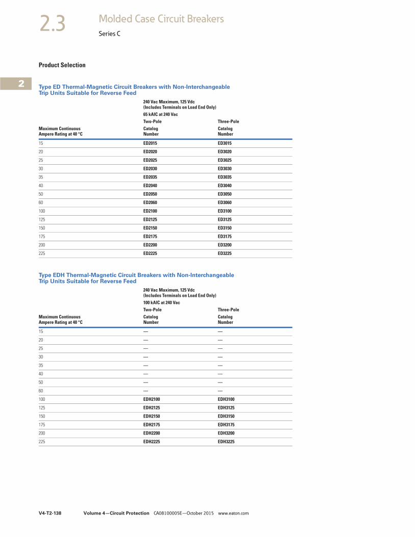
Type ED Thermal-Magnetic Circuit Breakers with Non-Interchangeable Trip Units Suitable for Reverse Feed
Type EDH Thermal-Magnetic Circuit Breakers with Non-Interchangeable Trip Units Suitable for Reverse Feed
Maximum ContinuousAmpere Rating at 40 °C
240 Vac Maximum, 125 Vdc (Includes Terminals on Load End Only)65 kAIC at 240 VacTwo-Pole Three-PoleCatalog Number
Catalog Number
15 ED2015 ED3015
20 ED2020 ED3020
25 ED2025 ED3025
30 ED2030 ED3030
35 ED2035 ED3035
40 ED2040 ED3040
50 ED2050 ED3050
60 ED2060 ED3060
100 ED2100 ED3100
125 ED2125 ED3125
150 ED2150 ED3150
175 ED2175 ED3175
200 ED2200 ED3200
225 ED2225 ED3225
Maximum ContinuousAmpere Rating at 40 °C
240 Vac Maximum, 125 Vdc (Includes Terminals on Load End Only)100 kAIC at 240 VacTwo-Pole Three-PoleCatalog Number
Catalog Number
15 — —
20 — —
25 — —
30 — —
35 — —
40 — —
50 — —
60 — —
100 EDH2100 EDH3100
125 EDH2125 EDH3125
150 EDH2150 EDH3150
175 EDH2175 EDH3175
200 EDH2200 EDH3200
225 EDH2225 EDH3225
Volume 4—Circuit Protection CA08100005E—October 2015 www.eaton.com V4-T2-139
2
2
2
2
2
2
2
2
2
2
2
2
2
2
2
2
2
2
2
2
2
2
2
2
2
2
2
2
2
2
2.3Molded Case Circuit Breakers
Series C
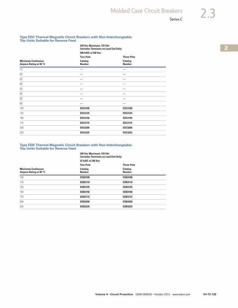
Type EDC Thermal-Magnetic Circuit Breakers with Non-Interchangeable Trip Units Suitable for Reverse Feed
Type EDB Thermal-Magnetic Circuit Breakers with Non-Interchangeable Trip Units Suitable for Reverse Feed
Maximum ContinuousAmpere Rating at 40 °C
240 Vac Maximum, 125 Vdc (Includes Terminals on Load End Only)200 kAIC at 240 VacTwo-Pole Three-PoleCatalog Number
Catalog Number
15 — —
20 — —
25 — —
30 — —
35 — —
40 — —
50 — —
60 — —
100 EDC2100 EDC3100
125 EDC2125 EDC3125
150 EDC2150 EDC3150
175 EDC2175 EDC3175
200 EDC2200 EDC3200
225 EDC2225 EDC3225
Maximum ContinuousAmpere Rating at 40 °C
240 Vac Maximum, 125 Vdc (Includes Terminals on Load End Only)22 kAIC at 240 VacTwo-Pole Three-PoleCatalog Number
Catalog Number
100 EDB2100 EDB3100
110 EDB2110 EDB3110
125 EDB2125 EDB3125
150 EDB2150 EDB3150
175 EDB2175 EDB3175
200 EDB2200 EDB3200
225 EDB2225 EDB3225
V4-T2-140 Volume 4—Circuit Protection CA08100005E—October 2015 www.eaton.com
2
2
2
2
2
2
2
2
2
2
2
2
2
2
2
2
2
2
2
2
2
2
2
2
2
2
2
2
2
2
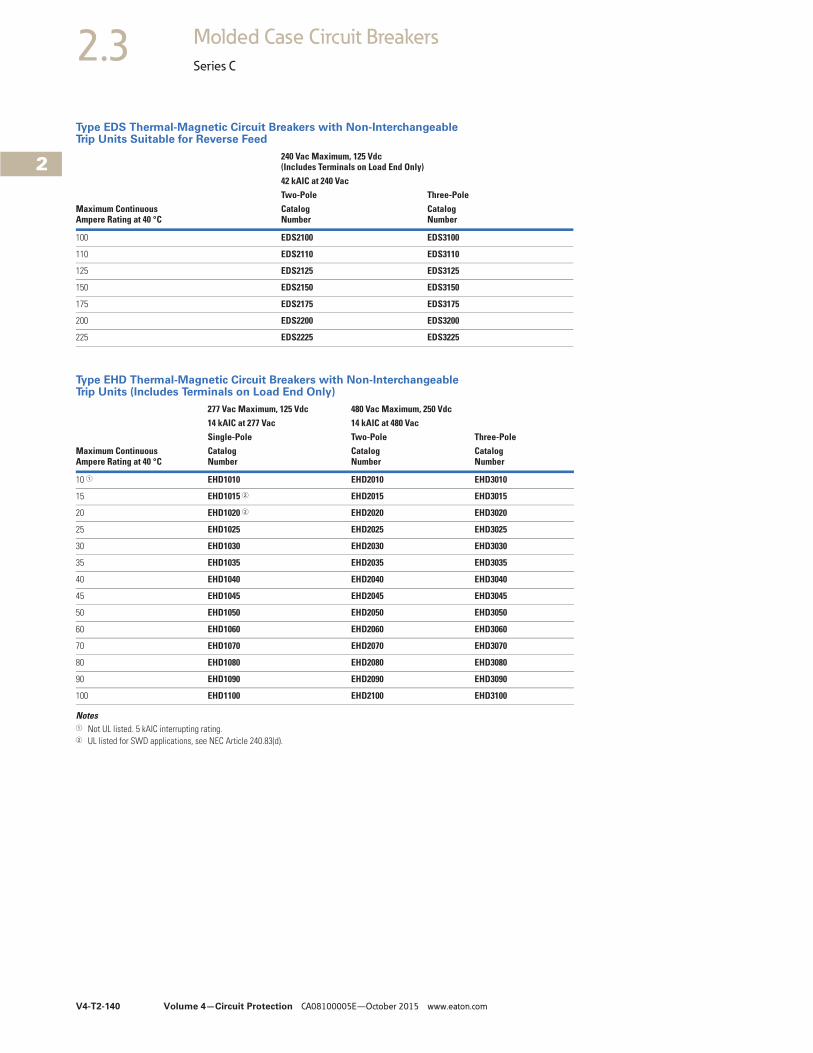
2.3 Molded Case Circuit Breakers
Series C
Type EDS Thermal-Magnetic Circuit Breakers with Non-Interchangeable Trip Units Suitable for Reverse Feed
Type EHD Thermal-Magnetic Circuit Breakers with Non-Interchangeable Trip Units (Includes Terminals on Load End Only)
Notes1 Not UL listed. 5 kAIC interrupting rating.2 UL listed for SWD applications, see NEC Article 240.83(d).
Maximum ContinuousAmpere Rating at 40 °C
240 Vac Maximum, 125 Vdc (Includes Terminals on Load End Only)42 kAIC at 240 VacTwo-Pole Three-PoleCatalog Number
Catalog Number
100 EDS2100 EDS3100
110 EDS2110 EDS3110
125 EDS2125 EDS3125
150 EDS2150 EDS3150
175 EDS2175 EDS3175
200 EDS2200 EDS3200
225 EDS2225 EDS3225
Maximum ContinuousAmpere Rating at 40 °C
277 Vac Maximum, 125 Vdc 480 Vac Maximum, 250 Vdc14 kAIC at 277 Vac 14 kAIC at 480 VacSingle-Pole Two-Pole Three-PoleCatalog Number
Catalog Number
Catalog Number
10 1 EHD1010 EHD2010 EHD3010
15 EHD1015 2 EHD2015 EHD3015
20 EHD1020 2 EHD2020 EHD3020
25 EHD1025 EHD2025 EHD3025
30 EHD1030 EHD2030 EHD3030
35 EHD1035 EHD2035 EHD3035
40 EHD1040 EHD2040 EHD3040
45 EHD1045 EHD2045 EHD3045
50 EHD1050 EHD2050 EHD3050
60 EHD1060 EHD2060 EHD3060
70 EHD1070 EHD2070 EHD3070
80 EHD1080 EHD2080 EHD3080
90 EHD1090 EHD2090 EHD3090
100 EHD1100 EHD2100 EHD3100

Volume 4—Circuit Protection CA08100005E—October 2015 www.eaton.com V4-T2-141
2
2
2
2
2
2
2
2
2
2
2
2
2
2
2
2
2
2
2
2
2
2
2
2
2
2
2
2
2
2
2.3Molded Case Circuit Breakers
Series C
Type FDB Thermal-Magnetic Circuit Breakers with Non-Interchangeable Trip Units(Includes Terminals on Load End Only)
Notes1 Not UL listed. 5 kAIC interrupting rating.2 UL listed for SWD applications, see NEC Article 240.83(d).
Maximum ContinuousAmpere Rating at 40 °C
600 Vac Maximum, 250 Vdc14 kAIC at 600 VacTwo-Pole Three-Pole Four-PoleCatalogNumber
CatalogNumber
CatalogNumber
10 1 FDB2010 FDB3010 FDB4010
15 FDB2015 FDB3015 FDB4015
20 FDB2020 FDB3020 FDB4020
25 FDB2025 FDB3025 FDB4025
30 FDB2030 FDB3030 FDB4030
35 FDB2035 FDB3035 FDB4035
40 FDB2040 FDB3040 FDB4040
45 FDB2045 FDB3045 FDB4045
50 FDB2050 FDB3050 FDB4050
60 FDB2060 FDB3060 FDB4060
70 FDB2070 FDB3070 FDB4070
80 FDB2080 FDB3080 FDB4080
90 FDB2090 FDB3090 FDB4090
100 FDB2100 FDB3100 FDB4100
110 FDB2110 FDB3110 FDB4110
125 FDB2125 FDB3125 FDB4125
150 FDB2150 FDB3150 FDB4150
V4-T2-142 Volume 4—Circuit Protection CA08100005E—October 2015 www.eaton.com
2
2
2
2
2
2
2
2
2
2
2
2
2
2
2
2
2
2
2
2
2
2
2
2
2
2
2
2
2
2
2.3 Molded Case Circuit Breakers
Series C
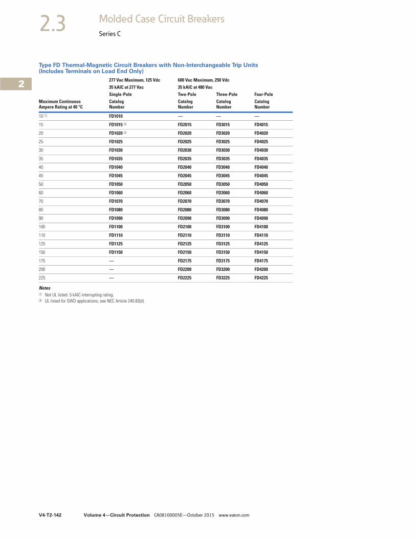
Type FD Thermal-Magnetic Circuit Breakers with Non-Interchangeable Trip Units(Includes Terminals on Load End Only)
Notes1 Not UL listed. 5 kAIC interrupting rating.2 UL listed for SWD applications, see NEC Article 240.83(d).
Maximum ContinuousAmpere Rating at 40 °C
277 Vac Maximum, 125 Vdc 600 Vac Maximum, 250 Vdc35 kAIC at 277 Vac 35 kAIC at 480 VacSingle-Pole Two-Pole Three-Pole Four-PoleCatalogNumber
CatalogNumber
CatalogNumber
CatalogNumber
10 1 FD1010 — — —
15 FD1015 2 FD2015 FD3015 FD4015
20 FD1020 2 FD2020 FD3020 FD4020
25 FD1025 FD2025 FD3025 FD4025
30 FD1030 FD2030 FD3030 FD4030
35 FD1035 FD2035 FD3035 FD4035
40 FD1040 FD2040 FD3040 FD4040
45 FD1045 FD2045 FD3045 FD4045
50 FD1050 FD2050 FD3050 FD4050
60 FD1060 FD2060 FD3060 FD4060
70 FD1070 FD2070 FD3070 FD4070
80 FD1080 FD2080 FD3080 FD4080
90 FD1090 FD2090 FD3090 FD4090
100 FD1100 FD2100 FD3100 FD4100
110 FD1110 FD2110 FD3110 FD4110
125 FD1125 FD2125 FD3125 FD4125
150 FD1150 FD2150 FD3150 FD4150
175 — FD2175 FD3175 FD4175
200 — FD2200 FD3200 FD4200
225 — FD2225 FD3225 FD4225
Volume 4—Circuit Protection CA08100005E—October 2015 www.eaton.com V4-T2-143
2
2
2
2
2
2
2
2
2
2
2
2
2
2
2
2
2
2
2
2
2
2
2
2
2
2
2
2
2
2
2.3Molded Case Circuit Breakers
Series C
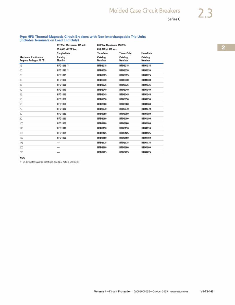
Type HFD Thermal-Magnetic Circuit Breakers with Non-Interchangeable Trip Units (Includes Terminals on Load End Only)
Note1 UL listed for SWD applications, see NEC Article 240.83(d).
Maximum ContinuousAmpere Rating at 40 °C
277 Vac Maximum, 125 Vdc 600 Vac Maximum, 250 Vdc65 kAIC at 277 Vac 65 kAIC at 480 VacSingle-Pole Two-Pole Three-Pole Four-PoleCatalogNumber
CatalogNumber
CatalogNumber
CatalogNumber
15 HFD1015 1 HFD2015 HFD3015 HFD4015
20 HFD1020 1 HFD2020 HFD3020 HFD4020
25 HFD1025 HFD2025 HFD3025 HFD4025
30 HFD1030 HFD2030 HFD3030 HFD4030
35 HFD1035 HFD2035 HFD3035 HFD4035
40 HFD1040 HFD2040 HFD3040 HFD4040
45 HFD1045 HFD2045 HFD3045 HFD4045
50 HFD1050 HFD2050 HFD3050 HFD4050
60 HFD1060 HFD2060 HFD3060 HFD4060
70 HFD1070 HFD2070 HFD3070 HFD4070
80 HFD1080 HFD2080 HFD3080 HFD4080
90 HFD1090 HFD2090 HFD3090 HFD4090
100 HFD1100 HFD2100 HFD3100 HFD4100
110 HFD1110 HFD2110 HFD3110 HFD4110
125 HFD1125 HFD2125 HFD3125 HFD4125
150 HFD1150 HFD2150 HFD3150 HFD4150
175 — HFD2175 HFD3175 HFD4175
200 — HFD2200 HFD3200 HFD4200
225 — HFD2225 HFD3225 HFD4225
V4-T2-144 Volume 4—Circuit Protection CA08100005E—October 2015 www.eaton.com
2
2
2
2
2
2
2
2
2
2
2
2
2
2
2
2
2
2
2
2
2
2
2
2
2
2
2
2
2
2
2.3 Molded Case Circuit Breakers
Series C
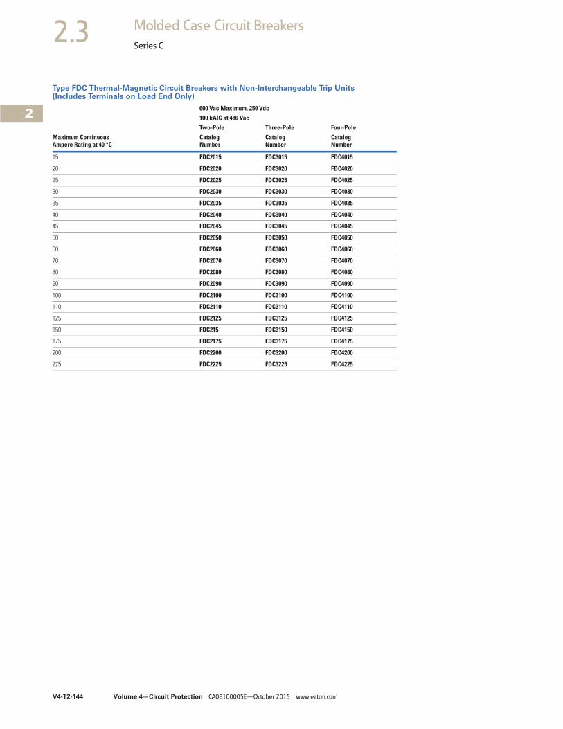
Type FDC Thermal-Magnetic Circuit Breakers with Non-Interchangeable Trip Units (Includes Terminals on Load End Only)
Maximum ContinuousAmpere Rating at 40 °C
600 Vac Maximum, 250 Vdc100 kAIC at 480 VacTwo-Pole Three-Pole Four-PoleCatalogNumber
CatalogNumber
CatalogNumber
15 FDC2015 FDC3015 FDC4015
20 FDC2020 FDC3020 FDC4020
25 FDC2025 FDC3025 FDC4025
30 FDC2030 FDC3030 FDC4030
35 FDC2035 FDC3035 FDC4035
40 FDC2040 FDC3040 FDC4040
45 FDC2045 FDC3045 FDC4045
50 FDC2050 FDC3050 FDC4050
60 FDC2060 FDC3060 FDC4060
70 FDC2070 FDC3070 FDC4070
80 FDC2080 FDC3080 FDC4080
90 FDC2090 FDC3090 FDC4090
100 FDC2100 FDC3100 FDC4100
110 FDC2110 FDC3110 FDC4110
125 FDC2125 FDC3125 FDC4125
150 FDC215 FDC3150 FDC4150
175 FDC2175 FDC3175 FDC4175
200 FDC2200 FDC3200 FDC4200
225 FDC2225 FDC3225 FDC4225
Volume 4—Circuit Protection CA08100005E—October 2015 www.eaton.com V4-T2-145
2
2
2
2
2
2
2
2
2
2
2
2
2
2
2
2
2
2
2
2
2
2
2
2
2
2
2
2
2
2
2.3Molded Case Circuit Breakers
Series C
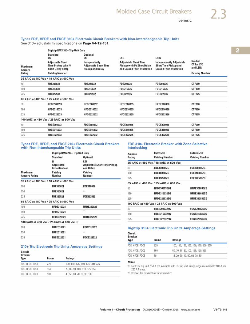
Types FDE, HFDE and FDCE 310+ Electronic Circuit Breakers with Non-Interchangeable Trip Units
See 310+ adjustability specifications on Page V4-T2-151.
Types FDE, HFDE, and FDCE 210+ Electronic Circuit Breakers with Non-Interchangeable Trip Units
210+ Trip Electronic Trip Units Amperage Settings
FDE 310+ Electronic Breaker with Zone Selective Interlocking
Digitrip 310+ Electronic Trip Units Amperage Settings
Notes1 For 210+ trip unit, 150 A not available with LSI trip unit; entire range is covered by 100 A and
225 A frames.2 Contact the product line for availability.
MaximumAmpere Rating
Digitrip RMS 310+ Trip Unit Only
Neutral CT for LSGand LSIG
StandardLS
OptionalLSI LSG LSIG
Adjustable Short Time Pickup with I2t Short Delay Ramp
Independently Adjustable Short Time Pickup and Delay
Adjustable Short Time Pickup with I2t Short Delay and Ground Fault Protection
Independently Adjustable Short Time Pickup and Ground Fault Protection
Catalog Number Catalog Number
35 kAIC at 480 Vac / 18 kAIC at 600 Vac
80 FDE308033 FDE308032 FDE308035 FDE308036 CTF080
160 FDE316033 FDE316032 FDE316035 FDE316036 CTF160
225 FDE322533 FDE322532 FDE322535 FDE322536 CTF225
65 kAIC at 480 Vac / 25 kAIC at 600 Vac
80 HFDE308033 HFDE308032 HFDE308035 HFDE308036 CTF080
160 HFDE316033 HFDE316032 HFDE316035 HFDE316036 CTF160
225 HFDE322533 HFDE322532 HFDE322535 HFDE322536 CTF225
100 kAIC at 480 Vac / 25 kAIC at 600 Vac
80 FDCE308033 FDCE308032 FDCE308035 FDCE308036 CTF080
160 FDCE316033 FDCE316032 FDCE316035 FDCE316036 CTF160
225 FDCE322533 FDCE322532 FDCE322535 FDCE322536 CTF225
Digitrip RMS 210+ Trip Unit OnlyStandard OptionalLIAdjustable Instantaneous
LSIAdjustable Short Time Pickup and Delay
Maximum Ampere Rating
Catalog Number
Catalog Number
35 kAIC at 480 Vac / 18 kAIC at 600 Vac
100 FDE310021 FDE310022
150 FDE315021 1
225 FDE322521 FDE322522
65 kAIC at 480 Vac / 25 kAIC at 600 Vac
100 HFDE310021 HFDE310022
150 HFDE315021 1
225 HFDE322521 HFDE322522
100 kAIC at 480 Vac / 25 kAIC at 600 Vac 2
100 FDCE310021 FDCE310022
150 FDCE315021 1
225 FDCE322521 FDCE322522
Circuit Breaker Type Frame Ratings
FDE, HFDE, FDCE 225 100, 110, 125, 150, 175, 200, 225
FDE, HFDE, FDCE 150 70, 80, 90, 100, 110, 125, 150
FDE, HFDE, FDCE 100 40, 50, 60, 70, 80, 90, 100
AmpereRating
LSI w/ZSI LSIG w/ZSICatalog Number Catalog Number
35 kAIC at 480 Vac / 18 kAIC at 600 Vac
80 FDE308032ZG FDE308036ZG
160 FDE316032ZG FDE316036ZG
225 FDE322532ZG FDE322536ZG
65 kAIC at 480 Vac / 25 kAIC at 600 Vac
80 HFDE308032ZG HFDE308036ZG
160 HFDE316032ZG HFDE316036ZG
225 HFDE322532ZG HFDE322536ZG
100 kAIC at 480 Vac / 25 kAIC at 600 Vac
80 FDCE308032ZG FDCE308036ZG
160 FDCE316032ZG FDCE316036ZG
225 FDCE322532ZG FDCE322536ZG
CircuitBreakerType Frame Ratings
FDE, HFDE, FDCE 225 100, 110, 125, 150, 160, 175, 200, 225
FDE, HFDE, FDCE 160 60, 70, 80, 90, 100, 125, 150, 160
FDE, HFDE, FDCE 80 15, 20, 30, 40, 50, 60, 70, 80
V4-T2-146 Volume 4—Circuit Protection CA08100005E—October 2015 www.eaton.com
2
2
2
2
2
2
2
2
2
2
2
2
2
2
2
2
2
2
2
2
2
2
2
2
2
2
2
2
2
2
2.3 Molded Case Circuit Breakers
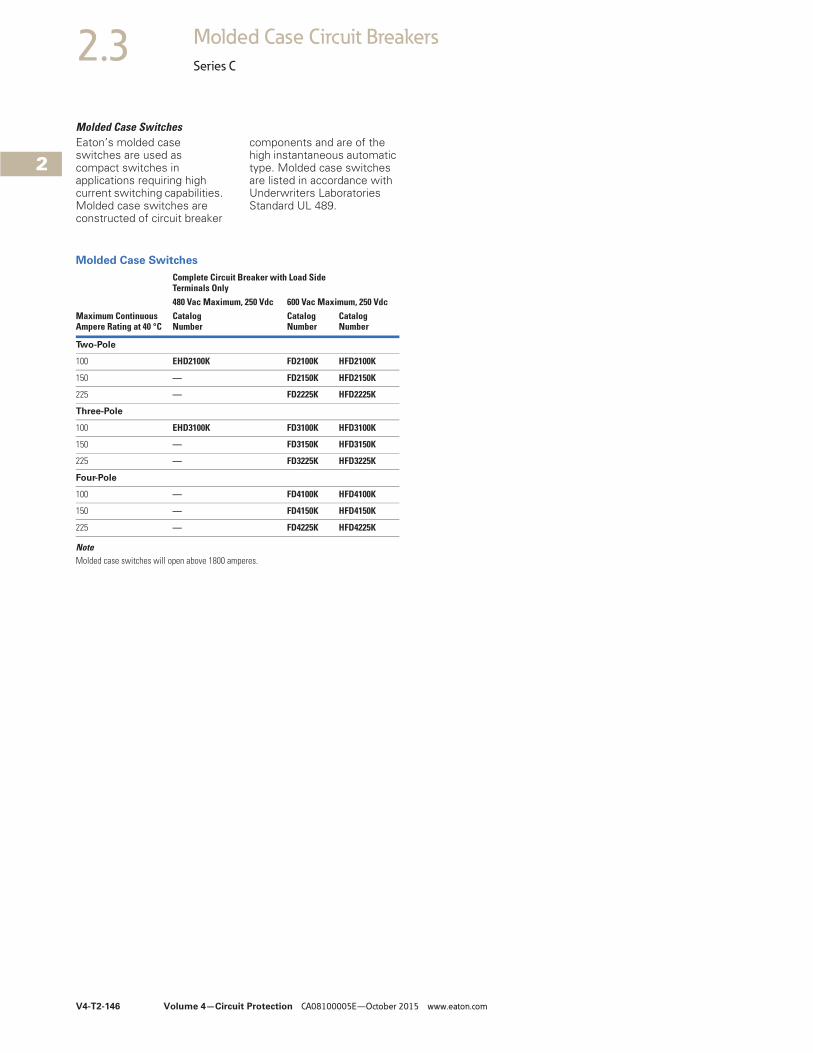
Series C
Molded Case SwitchesEaton’s molded case switches are used as compact switches in applications requiring high current switching capabilities. Molded case switches are constructed of circuit breaker
components and are of the high instantaneous automatic type. Molded case switches are listed in accordance with Underwriters Laboratories Standard UL 489.
Molded Case Switches
NoteMolded case switches will open above 1800 amperes.
Maximum Continuous Ampere Rating at 40 °C
Complete Circuit Breaker with Load Side Terminals Only480 Vac Maximum, 250 Vdc 600 Vac Maximum, 250 VdcCatalogNumber
CatalogNumber
CatalogNumber
Two-Pole
100 EHD2100K FD2100K HFD2100K
150 — FD2150K HFD2150K
225 — FD2225K HFD2225K
Three-Pole
100 EHD3100K FD3100K HFD3100K
150 — FD3150K HFD3150K
225 — FD3225K HFD3225K
Four-Pole
100 — FD4100K HFD4100K
150 — FD4150K HFD4150K
225 — FD4225K HFD4225K

Volume 4—Circuit Protection CA08100005E—October 2015 www.eaton.com V4-T2-147
2
2
2
2
2
2
2
2
2
2
2
2
2
2
2
2
2
2
2
2
2
2
2
2
2
2
2
2
2
2
2.3Molded Case Circuit Breakers
Series C
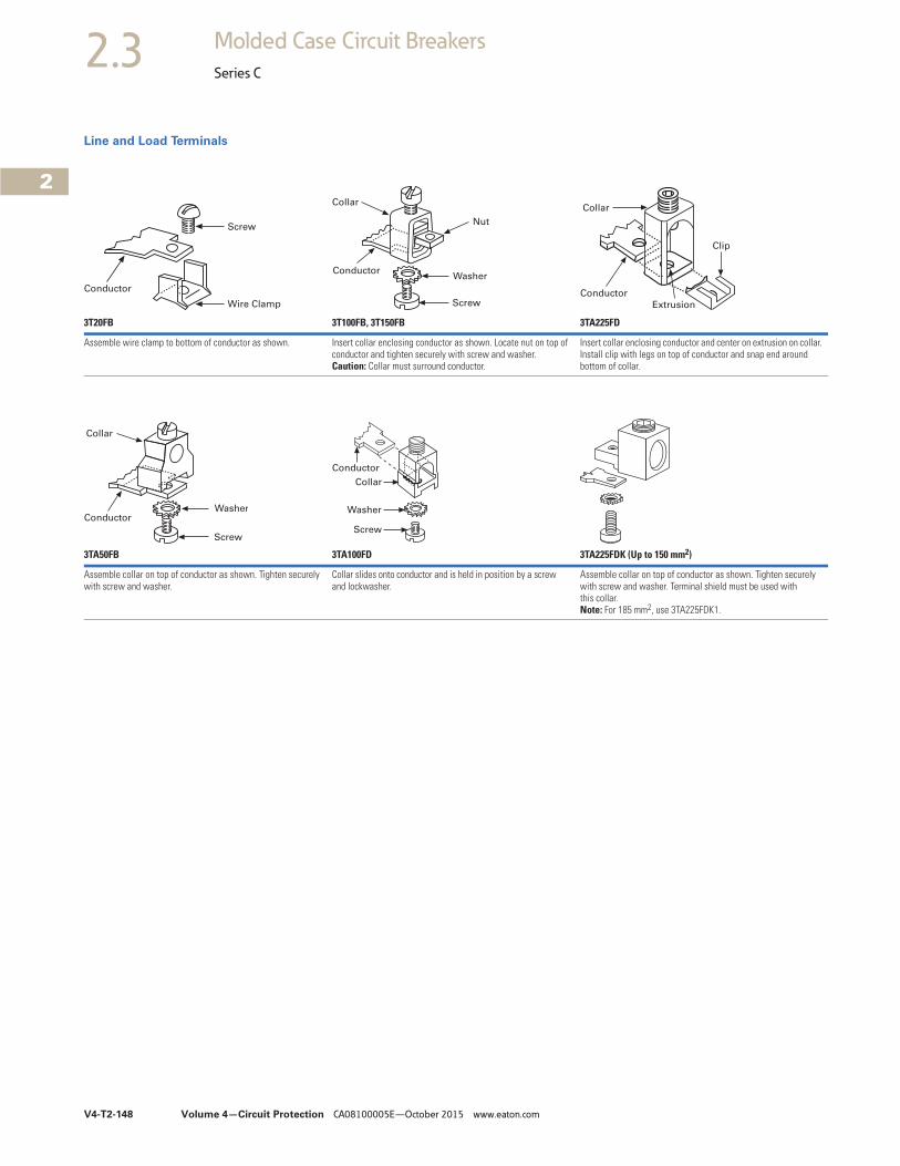
Accessories Selection Guide and Ordering Information
Line and Load TerminalsLine and load terminals provide wire connecting capabilities for specific ranges of continuous current ratings and wire types. Except as noted, terminals comply with Underwriters Laboratories Standards UL 486A and UL 486B. Unless otherwise specified, F-Frame circuit breakers are factory equipped with load terminals only.
Ordering InformationF-Frame circuit breakers and molded case switches have load terminals only as standard equipment. When standard line-end terminals (same as standard load-end terminals) are required, add Suffix L to the circuit breaker catalog number. When non-standard or optional line and/or load terminals are required, order by style number. Specify if factory installation is required.
Line and Load Terminals
Notes1 Use on FDE, HFDE and FDCE electronic trip only.2 Not for use with ED, EDH, EDC breakers.3 Includes terminal shield kit. Adds approximately 3 inches (76.2) to breaker height. Available for use on three-pole breaker only.
MaximumBreakerAmperes
Terminal BodyMaterial Wire Type
AWG WireRange
Metric WireRange mm2
Package of Three TerminalsCatalog Number
Standard Pressure Type Terminals
20 (EHD) Steel Cu/AI 14–10 2.5–4 3T20FB 2
100 Steel Cu/AI 14–1/0 2.5–50 3T100FB
225 Aluminum Cu/AI 4–4/0 25–95 3TA225FD
Optional Pressure Terminals
50 Aluminum Cu/AI 14–4 2.5–25 3TA50FB 2
100 Aluminum Cu/AI 14–1/0 2.5–50 3TA100FD
200 Stainless steel Cu 4–4/0 25–95 3T150FB
225 Copper Cu 4–4/0 25–95 3T225FD
225 Aluminum Cu/AI 6–300 kcmil 16–150 3TA225FDK 3
V4-T2-148 Volume 4—Circuit Protection CA08100005E—October 2015 www.eaton.com
2
2
2
2
2
2
2
2
2
2
2
2
2
2
2
2
2
2
2
2
2
2
2
2
2
2
2
2
2
2
2.3 Molded Case Circuit Breakers
Series C
Line and Load Terminals
3T20FB 3T100FB, 3T150FB 3TA225FD
Assemble wire clamp to bottom of conductor as shown. Insert collar enclosing conductor as shown. Locate nut on top of conductor and tighten securely with screw and washer. Caution: Collar must surround conductor.
Insert collar enclosing conductor and center on extrusion on collar. Install clip with legs on top of conductor and snap end around bottom of collar.
3TA50FB 3TA100FD 3TA225FDK (Up to 150 mm2)
Assemble collar on top of conductor as shown. Tighten securely with screw and washer.
Collar slides onto conductor and is held in position by a screw and lockwasher.
Assemble collar on top of conductor as shown. Tighten securely with screw and washer. Terminal shield must be used with this collar.Note: For 185 mm2, use 3TA225FDK1.
Screw
Wire Clamp
Conductor
Screw
Washer
Collar
Conductor
Nut
Conductor
Extrusion
Clip
Collar
Collar
Screw
WasherConductor
Conductor
Collar
Washer
Screw
Volume 4—Circuit Protection CA08100005E—October 2015 www.eaton.com V4-T2-149
2
2
2
2
2
2
2
2
2
2
2
2
2
2
2
2
2
2
2
2
2
2
2
2
2
2
2
2
2
2
2.3Molded Case Circuit Breakers
Series C
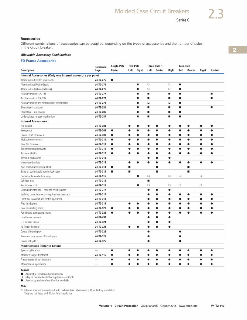
AccessoriesDifferent combinations of accessories can be supplied, depending on the types of accessories and the number of poles in the circuit breaker.
Allowable Accessory Combinations
FD Frame Accessories
Legend■ Applicable in indicated pole position❏ May be mounted on left or right pole—not both● Accessory available/modification available
Note1 Internal accessories are listed with Underwriters Laboratories (UL) for factory installation.
They are not listed with UL for field installation.
DescriptionReference Page
Single-Pole Two-Pole Three-Pole 1 Four-PoleCenter Left Right Left Center Right Left Center Right Neutral
Internal Accessories (Only one internal accessory per pole)
Alarm lockout switch (make only) V4-T2-275 ■
Alarm lockout (Make/Break) V4-T2-275 ■ ❏ ❏ ■
Alarm lockout (2Make/2Break) V4-T2-275 ■ ❏ ❏ ■
Auxiliary switch (1A, 1B) V4-T2-277 ■ ■ ■ ■ ■
Auxiliary switch (2A, 2B) V4-T2-277 ■ ■ ■ ■ ■
Auxiliary switch and alarm switch combination V4-T2-279 ■ ❏ ❏ ■
Shunt trip—standard V4-T2-281 ■ ■ ■ ■ ■
Shunt trip—low energy V4-T2-285 ■ ■ ■ ■
Undervoltage release mechanism V4-T2-287 ■ ■ ■ ■
External Accessories
End cap kit V4-T2-308 ● ● ● ● ● ● ● ● ●
Keeper nut V4-T2-308 ● ● ● ● ● ● ● ● ● ●
Control wire terminal kit V4-T2-309 ● ● ● ● ● ● ● ● ● ●
Multiwire connectors V4-T2-310 ● ● ● ● ● ● ● ● ● ●
Rear fed terminals V4-T2-310 ● ● ● ● ● ● ● ● ● ●
Base mounting hardware V4-T2-310 ● ● ● ● ● ● ● ● ● ●
Terminal shields V4-T2-312 ● ● ● ● ● ● ● ● ● ●
Terminal end covers V4-T2-313 ● ● ●
Interphase barriers V4-T2-313 ● ● ● ● ● ● ● ● ●
Non-padlockable handle block V4-T2-314 ■ ■ ■ ■
Snap-on padlockable handle lock hasp V4-T2-314 ■ ■ ■ ■
Padlockable handle lock hasp V4-T2-315 ■ ❏ ❏ ❏ ❏
Cylinder lock V4-T2-315 ■
Key interlock kit V4-T2-316 ■ ❏ ❏ ❏ ❏
Sliding bar interlock—requires two breakers V4-T2-317 ● ● ●
Walking beam interlock—requires two breakers V4-T2-317 ● ● ● ● ● ● ●
Electrical (solenoid and motor) operators V4-T2-318 ● ● ● ● ● ● ●
Plug-in adapters V4-T2-319 ● ● ● ● ● ● ● ● ●
Rear connecting studs V4-T2-321 ● ● ● ● ● ● ● ● ● ●
Panelboard connecting straps V4-T2-322 ● ● ● ● ● ● ● ● ● ●
Handle mechanisms V4-T2-430 ● ● ●
LFD current limiter V4-T2-324 ● ● ●
IQ Energy Sentinel V4-T2-324 ● ● ● ● ●
Cause of trip display V4-T2-325 ● ●
Remote mount cause of trip display V4-T2-325 ● ●
Cause of trip LED V4-T2-325 ● ●
Modifications (Refer to Eaton)
Special calibration — ● ● ● ● ● ● ● ● ● ●
Moisture fungus treatment V4-T2-116 ● ● ● ● ● ● ● ● ● ●
Freeze-tested circuit breakers — ● ● ● ● ● ● ● ● ● ●
Marine/naval application — ● ● ● ● ● ● ● ● ● ●
V4-T2-150 Volume 4—Circuit Protection CA08100005E—October 2015 www.eaton.com
2
2
2
2
2
2
2
2
2
2
2
2
2
2
2
2
2
2
2
2
2
2
2
2
2
2
2
2
2
2
2.3 Molded Case Circuit Breakers
Series C
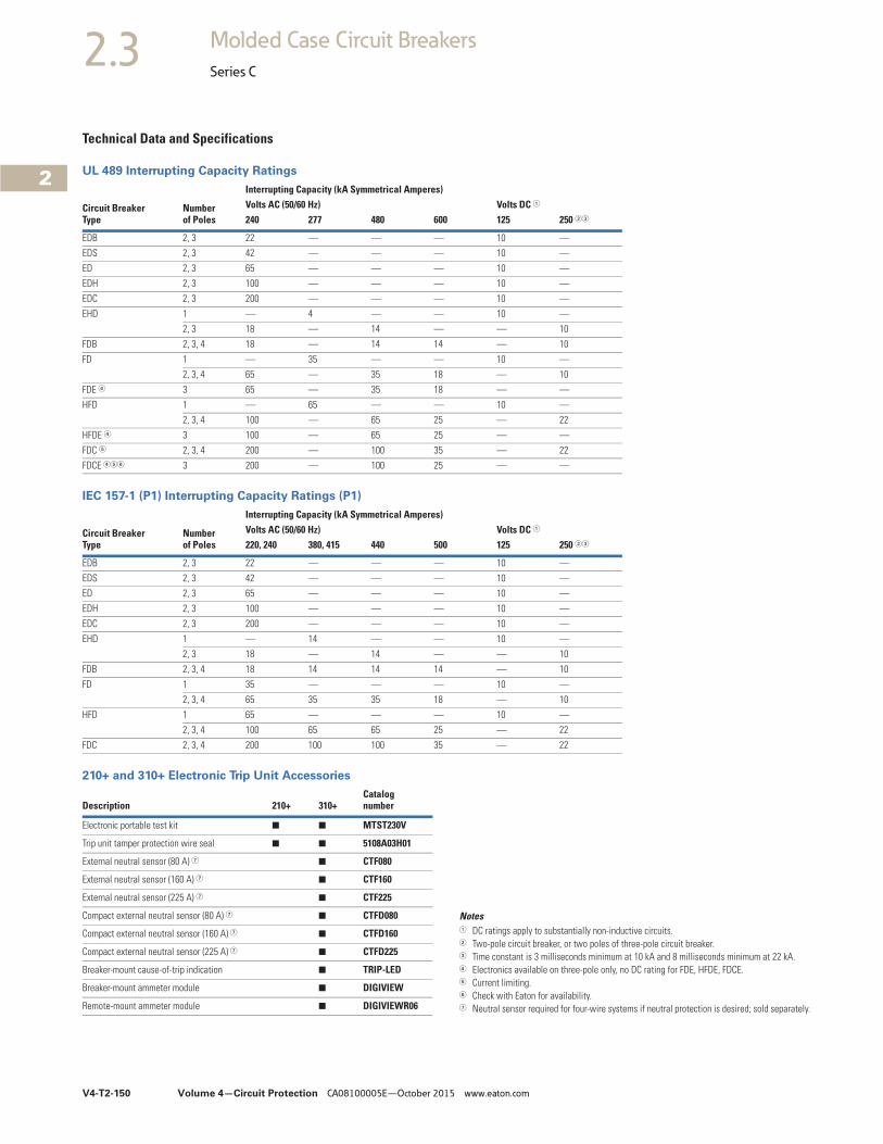
Technical Data and Specifications
UL 489 Interrupting Capacity Ratings
IEC 157-1 (P1) Interrupting Capacity Ratings (P1)
210+ and 310+ Electronic Trip Unit Accessories
Notes1 DC ratings apply to substantially non-inductive circuits.2 Two-pole circuit breaker, or two poles of three-pole circuit breaker.3 Time constant is 3 milliseconds minimum at 10 kA and 8 milliseconds minimum at 22 kA.4 Electronics available on three-pole only, no DC rating for FDE, HFDE, FDCE.5 Current limiting.6 Check with Eaton for availability.7 Neutral sensor required for four-wire systems if neutral protection is desired; sold separately.
Circuit BreakerType
Number of Poles
Interrupting Capacity (kA Symmetrical Amperes)Volts AC (50/60 Hz) Volts DC 1
240 277 480 600 125 250 23
EDB 2, 3 22 — — — 10 —
EDS 2, 3 42 — — — 10 —
ED 2, 3 65 — — — 10 —
EDH 2, 3 100 — — — 10 —
EDC 2, 3 200 — — — 10 —
EHD 1 — 4 — — 10 —
2, 3 18 — 14 — — 10
FDB 2, 3, 4 18 — 14 14 — 10
FD 1 — 35 — — 10 —
2, 3, 4 65 — 35 18 — 10
FDE 4 3 65 — 35 18 — —
HFD 1 — 65 — — 10 —
2, 3, 4 100 — 65 25 — 22
HFDE 4 3 100 — 65 25 — —
FDC 5 2, 3, 4 200 — 100 35 — 22
FDCE 456 3 200 — 100 25 — —
Circuit BreakerType
Numberof Poles
Interrupting Capacity (kA Symmetrical Amperes)Volts AC (50/60 Hz) Volts DC 1
220, 240 380, 415 440 500 125 250 23
EDB 2, 3 22 — — — 10 —
EDS 2, 3 42 — — — 10 —
ED 2, 3 65 — — — 10 —
EDH 2, 3 100 — — — 10 —
EDC 2, 3 200 — — — 10 —
EHD 1 — 14 — — 10 —
2, 3 18 — 14 — — 10
FDB 2, 3, 4 18 14 14 14 — 10
FD 1 35 — — — 10 —
2, 3, 4 65 35 35 18 — 10
HFD 1 65 — — — 10 —
2, 3, 4 100 65 65 25 — 22
FDC 2, 3, 4 200 100 100 35 — 22
Description 210+ 310+Catalog number
Electronic portable test kit ■ ■ MTST230V
Trip unit tamper protection wire seal ■ ■ 5108A03H01
External neutral sensor (80 A) 7 ■ CTF080
External neutral sensor (160 A) 7 ■ CTF160
External neutral sensor (225 A) 7 ■ CTF225
Compact external neutral sensor (80 A) 7 ■ CTFD080
Compact external neutral sensor (160 A) 7 ■ CTFD160
Compact external neutral sensor (225 A) 7 ■ CTFD225
Breaker-mount cause-of-trip indication ■ TRIP-LED
Breaker-mount ammeter module ■ DIGIVIEW
Remote-mount ammeter module ■ DIGIVIEWR06
Volume 4—Circuit Protection CA08100005E—October 2015 www.eaton.com V4-T2-151
2
2
2
2
2
2
2
2
2
2
2
2
2
2
2
2
2
2
2
2
2
2
2
2
2
2
2
2
2
2
2.3Molded Case Circuit Breakers
Series C
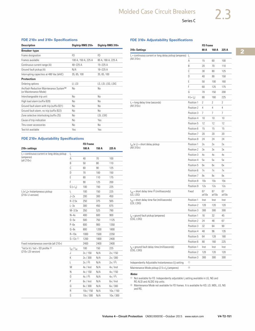
FDE 210+ and 310+ Specifications
FDE 210+ Adjustability Specifications
Description Digitrip RMS 210+ Digitrip RMS 310+
Breaker type
Frame designation FD FD
Frames available 100 A, 150 A, 225 A 80 A, 160 A, 225 A
Continuous current range (A) 40–225 A 15–225 A
Ground fault pickup (A) N/A 16–225 A
Interrupting capacities at 480 Vac (kAIC) 35, 65, 100 35, 65, 100
Protection
Ordering options LI, LSI LS, LSI, LSG, LSIG
Arcflash Reduction Maintenance System™ (or Maintenance Mode)
No No
Interchangeable trip unit No No
High load alarm (suffix B20) No No
Ground fault alarm with trip (suffix B21) No No
Ground fault alarm, no trip (suffix B22) No No
Zone selective interlocking (suffix ZG) No LSI, LSIG
Cause of trip indication No Yes
Thru-cover accessories No No
Test kit available Yes Yes
FD Frame210+ settings 100 A 150 A 225 A
Ir = continuous current or long delay pickup (amperes)(all 210+)
IrA 40 70 100
B 50 80 110
C 60 90 125
D 70 100 150
E 80 110 175
F 90 125 200
G (= In) 100 150 225
Ii (x In)= Instantaneous pickup(210+ LI version)
Ii 100 150 225
J–2x 200 300 450
K–2.5x 250 375 565
L–3x 300 450 675
M–3.5x 350 525 790
N–4x 400 600 900
O–5x 500 750 1125
P–6x 600 900 1350
Q–8x 800 1200 1800
R–10x 1000 1500 2250
S–12x 1 1200 1800 2400
Fixed instantaneous override (all 210+) 2400 2400 2400
“Isd (x Ir) / tsd = SD profile 2(210+ LSI version)
Isd / tsd 100 150 225
J 2x / 150 N/A 2x / 150
K 2x / 300 N/A 2x / 300
L 2x / I2t N/A 2x / I2t
M 4x / Inst N/A 4x / Inst
N 4x / 150 N/A 4x / 150
O 4x / I2t N/A 4x / I2t
P 6x / Inst N/A 6x / Inst
Q 6x / 300 N/A 6x / 300
R 10x / 150 N/A 10x / 150
S 10x / 300 N/A 10x / 300
FDE 310+ Adjustability Specifications
Notes1 Not available for FD. Independently adjustable Ii setting available in LG, NG and
RG ALSI and ALSIG trip units.2 Maintenance Mode not available for FD frames. It is available for KD, LD, MDL, LG, NG
and RG.
FD Frame310+ Settings 80 A 160 A 225 A
Ir = continuous current or long delay pickup (amperes)(All 310+)
Ir
A 15 60 100
B 20 70 110
C 30 80 125
D 40 90 150
E 50 100 160
F 60 125 175
G 70 150 200
H (= In) 80 160 225
tr = long delay time (seconds) (All 310+)
Position 1 2 2 2
Position 2 4 4 4
Position 3 7 7 7
Position 4 10 10 10
Position 5 12 12 12
Position 6 15 15 15
Position 7 20 20 20
Position 8 24 24 24
Isd (x Ir) = short delay pickup(All 310+)
Position 1 2x 2x 2x
Position 2 3x 3x 3x
Position 3 4x 4x 4x
Position 4 5x 5x 5x
Position 5 6x 6x 6x
Position 6 7x 7x 7x
Position 7 8x 8x 8x
Position 8 10x 10x 10x
Position 9 12x 12x 12x
tsd = short delay time I2t (milliseconds)(LS, LSG)
Fixed 67 at10x
67 at10x
67 at10x
tsd = short delay time flat (milliseconds)(LSI, LSIG)
Position 1 Inst Inst Inst
Position 2 120 120 120
Position 3 300 300 300
Ig = gound fault pickup (amperes)(LSG, LSIG)
Position 1 16 32 45
Position 2 24 48 67
Position 3 32 64 90
Position 4 48 96 135
Position 5 64 128 180
Position 6 80 160 225
tg = ground fault delay time (milliseconds)(LSG, LSIG)
Position 1 Inst Inst Inst
Position 2 120 120 120
Position 3 300 300 300
Independently Adjustable Instantaneous (Ii) setting 1
Maintenance Mode pickup (2.5 x In) (amperes) 2
V4-T2-152 Volume 4—Circuit Protection CA08100005E—October 2015 www.eaton.com
2
2
2
2
2
2
2
2
2
2
2
2
2
2
2
2
2
2
2
2
2
2
2
2
2
2
2
2
2
2
2.3 Molded Case Circuit Breakers
Series C
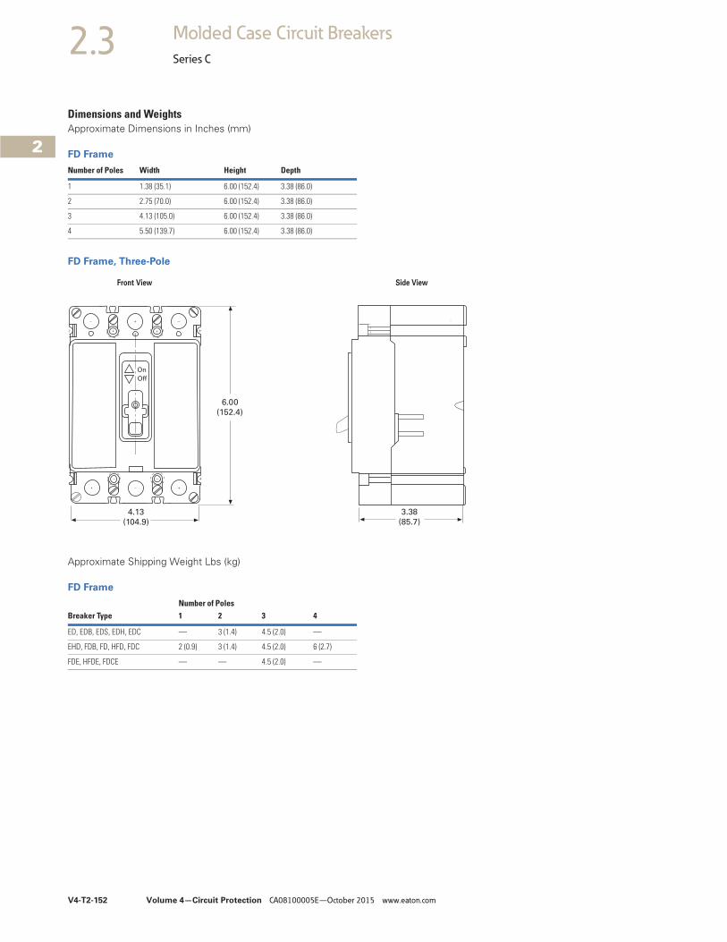
Dimensions and WeightsApproximate Dimensions in Inches (mm)
FD Frame
FD Frame, Three-Pole
Approximate Shipping Weight Lbs (kg)
FD Frame
Number of Poles Width Height Depth
1 1.38 (35.1) 6.00 (152.4) 3.38 (86.0)
2 2.75 (70.0) 6.00 (152.4) 3.38 (86.0)
3 4.13 (105.0) 6.00 (152.4) 3.38 (86.0)
4 5.50 (139.7) 6.00 (152.4) 3.38 (86.0)
3.38
(85.7)
6.00
(152.4)
4.13
(104.9)
On
Off
Front View Side View
Breaker TypeNumber of Poles1 2 3 4
ED, EDB, EDS, EDH, EDC — 3 (1.4) 4.5 (2.0) —
EHD, FDB, FD, HFD, FDC 2 (0.9) 3 (1.4) 4.5 (2.0) 6 (2.7)
FDE, HFDE, FDCE — — 4.5 (2.0) —

Volume 4—Circuit Protection CA08100005E—October 2015 www.eaton.com V4-T2-153
2
2
2
2
2
2
2
2
2
2
2
2
2
2
2
2
2
2
2
2
2
2
2
2
2
2
2
2
2
2
2.3Molded Case Circuit Breakers
Series C
Typical J-Frame Breaker ContentsDescription Page
Product Overview . . . . . . . . . . . . . . . . . . . . . . . . . . V4-T2-116
Standards and Certifications . . . . . . . . . . . . . . . . . . V4-T2-117
Quick Reference . . . . . . . . . . . . . . . . . . . . . . . . . . . V4-T2-118
G-Frame (15–100 Amperes) . . . . . . . . . . . . . . . . . . . V4-T2-121
F-Frame (10–225 Amperes) . . . . . . . . . . . . . . . . . . . V4-T2-135
J-Frame (70–250 Amperes)Catalog Number Selection . . . . . . . . . . . . . . . . . V4-T2-154
Product Selection . . . . . . . . . . . . . . . . . . . . . . . . V4-T2-155
Accessories . . . . . . . . . . . . . . . . . . . . . . . . . . . . V4-T2-158
Technical Data and Specifications. . . . . . . . . . . . V4-T2-159
Dimensions and Weights . . . . . . . . . . . . . . . . . . V4-T2-160
K-Frame (70–400 Amperes) . . . . . . . . . . . . . . . . . . . V4-T2-161
L-Frame (125–600 Amperes) . . . . . . . . . . . . . . . . . . V4-T2-185
M-Frame (300–800 Amperes) . . . . . . . . . . . . . . . . . V4-T2-211
N-Frame (400–1200 Amperes). . . . . . . . . . . . . . . . . V4-T2-222R-Frame (800–2500 Amperes) . . . . . . . . . . . . . . . . . V4-T2-237
Motor Circuit Protectors (MCP) . . . . . . . . . . . . . . . . V4-T2-256
Motor Protection Circuit Breakers (MPCB) . . . . . . . V4-T2-267
Type ELC Current Limiter Attachment (Size 0–4) . . . . . V4-T2-269
Current Limiting Circuit Breaker Module. . . . . . . . . . . V4-T2-270Internal Accessories. . . . . . . . . . . . . . . . . . . . . . . . . V4-T2-273External Accessories . . . . . . . . . . . . . . . . . . . . . . . . V4-T2-304
J-Frame (70–250 Amperes)Product Description● All Eaton’s J-Frame circuit
breakers are HACR rated● J-Frame circuit breakers are
available as individual components (frame, trip unit, terminals), or factory assembled complete breakers
● J-Frame circuit breakers with non-interchangeable trip units are suitable for reverse feed use
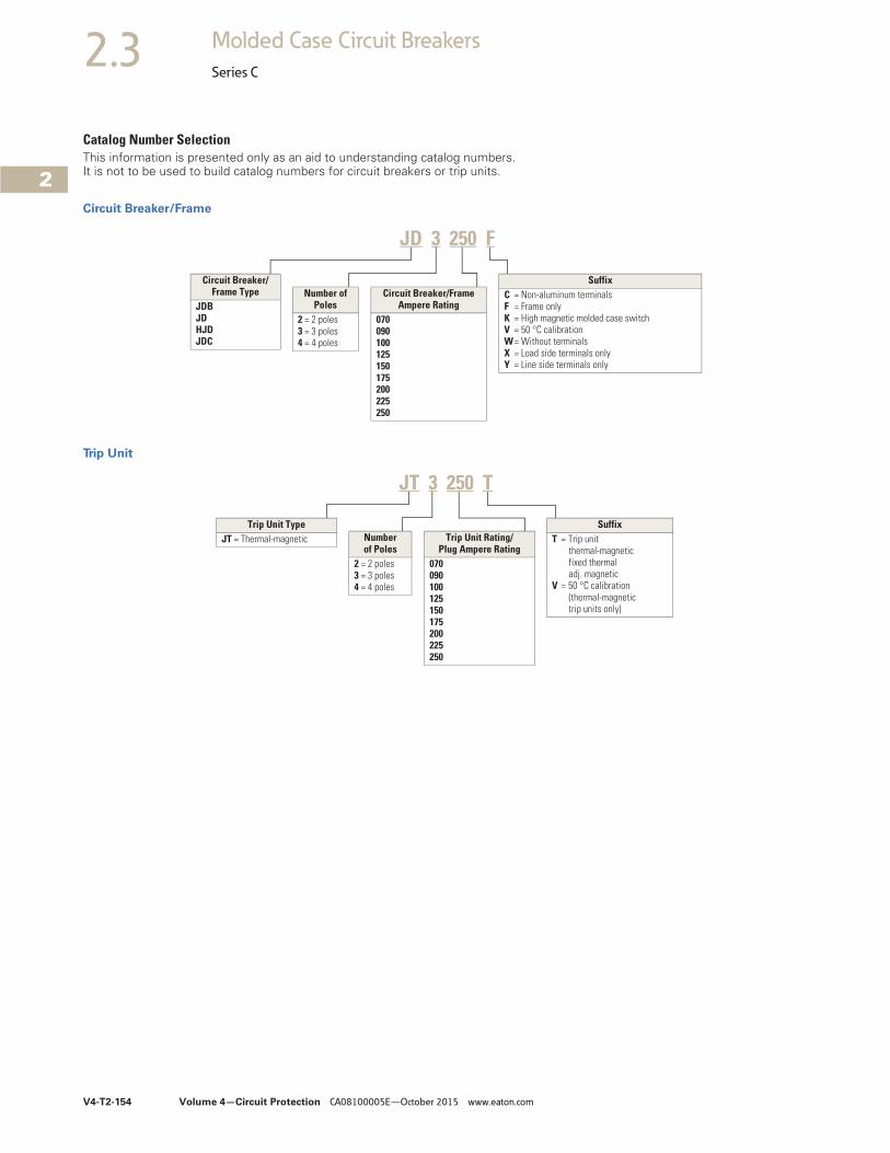
V4-T2-154 Volume 4—Circuit Protection CA08100005E—October 2015 www.eaton.com
2
2
2
2
2
2
2
2
2
2
2
2
2
2
2
2
2
2
2
2
2
2
2
2
2
2
2
2
2
2
2.3 Molded Case Circuit Breakers
Series C
Catalog Number SelectionThis information is presented only as an aid to understanding catalog numbers. It is not to be used to build catalog numbers for circuit breakers or trip units.
Circuit Breaker/Frame
Trip Unit
JD 3 250 F
Circuit Breaker/Frame Type
JDBJDHJDJDC
Number of Poles
2 = 2 poles3 = 3 poles4 = 4 poles
Circuit Breaker/Frame Ampere Rating
070090100125150175200225250
SuffixC = Non-aluminum terminalsF = Frame onlyK = High magnetic molded case switchV = 50 °C calibrationW= Without terminalsX = Load side terminals onlyY = Line side terminals only
Trip Unit TypeJT = Thermal-magnetic Number
of Poles2 = 2 poles3 = 3 poles4 = 4 poles
SuffixT = Trip unit
thermal-magneticfixed thermaladj. magnetic
V = 50 °C calibration (thermal-magnetictrip units only)
Trip Unit Rating/Plug Ampere Rating
070090100125150175200225250
JT 3 250 T
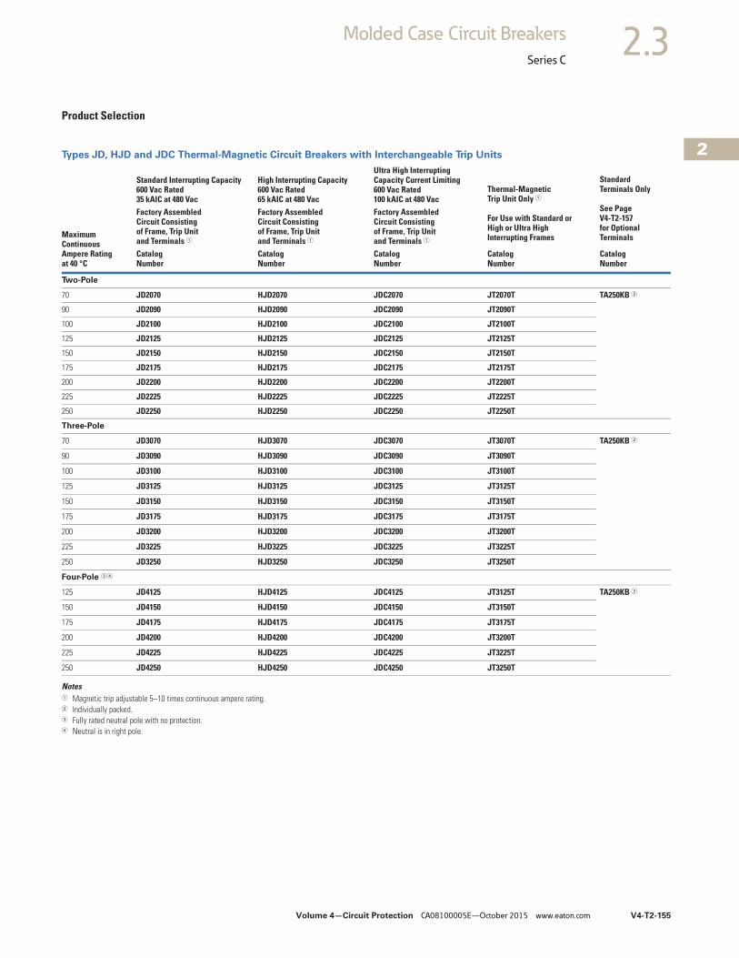
Volume 4—Circuit Protection CA08100005E—October 2015 www.eaton.com V4-T2-155
2
2
2
2
2
2
2
2
2
2
2
2
2
2
2
2
2
2
2
2
2
2
2
2
2
2
2
2
2
2
2.3Molded Case Circuit Breakers
Series C
Product Selection
Types JD, HJD and JDC Thermal-Magnetic Circuit Breakers with Interchangeable Trip Units
Notes1 Magnetic trip adjustable 5–10 times continuous ampere rating.2 Individually packed.3 Fully rated neutral pole with no protection.4 Neutral is in right pole.
Maximum Continuous Ampere Rating at 40 °C
Standard Interrupting Capacity600 Vac Rated35 kAIC at 480 Vac
High Interrupting Capacity 600 Vac Rated65 kAIC at 480 Vac
Ultra High InterruptingCapacity Current Limiting600 Vac Rated100 kAIC at 480 Vac
Thermal-MagneticTrip Unit Only 1
For Use with Standard orHigh or Ultra HighInterrupting Frames
StandardTerminals Only
See PageV4-T2-157for OptionalTerminals
Factory AssembledCircuit Consistingof Frame, Trip Unit and Terminals 1
Factory AssembledCircuit Consistingof Frame, Trip Unit and Terminals 1
Factory AssembledCircuit Consistingof Frame, Trip Unit and Terminals 1
CatalogNumber
CatalogNumber
CatalogNumber
CatalogNumber
CatalogNumber
Two-Pole
70 JD2070 HJD2070 JDC2070 JT2070T TA250KB 2
90 JD2090 HJD2090 JDC2090 JT2090T
100 JD2100 HJD2100 JDC2100 JT2100T
125 JD2125 HJD2125 JDC2125 JT2125T
150 JD2150 HJD2150 JDC2150 JT2150T
175 JD2175 HJD2175 JDC2175 JT2175T
200 JD2200 HJD2200 JDC2200 JT2200T
225 JD2225 HJD2225 JDC2225 JT2225T
250 JD2250 HJD2250 JDC2250 JT2250T
Three-Pole
70 JD3070 HJD3070 JDC3070 JT3070T TA250KB 2
90 JD3090 HJD3090 JDC3090 JT3090T
100 JD3100 HJD3100 JDC3100 JT3100T
125 JD3125 HJD3125 JDC3125 JT3125T
150 JD3150 HJD3150 JDC3150 JT3150T
175 JD3175 HJD3175 JDC3175 JT3175T
200 JD3200 HJD3200 JDC3200 JT3200T
225 JD3225 HJD3225 JDC3225 JT3225T
250 JD3250 HJD3250 JDC3250 JT3250T
Four-Pole 34
125 JD4125 HJD4125 JDC4125 JT3125T TA250KB 2
150 JD4150 HJD4150 JDC4150 JT3150T
175 JD4175 HJD4175 JDC4175 JT3175T
200 JD4200 HJD4200 JDC4200 JT3200T
225 JD4225 HJD4225 JDC4225 JT3225T
250 JD4250 HJD4250 JDC4250 JT3250T
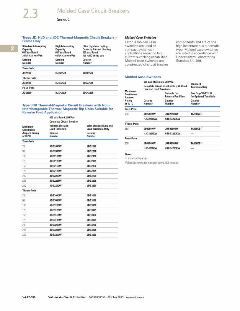
V4-T2-156 Volume 4—Circuit Protection CA08100005E—October 2015 www.eaton.com
2
2
2
2
2
2
2
2
2
2
2
2
2
2
2
2
2
2
2
2
2
2
2
2
2
2
2
2
2
2
2.3 Molded Case Circuit Breakers
Series C
Types JD, HJD and JDC Thermal-Magnetic Circuit Breakers—Frame Only
Type JDB Thermal-Magnetic Circuit Breakers with Non-Interchangeable Thermal-Magnetic Trip Units Suitable for Reverse Feed Application
Standard Interrupting Capacity600 Vac Rated35 kAIC at 480 Vac
High Interrupting Capacity 600 Vac Rated65 kAIC at 480 Vac
Ultra High Interrupting Capacity Current Limiting600 Vac Rated100 kAIC at 480 Vac
CatalogNumber
CatalogNumber
CatalogNumber
Two-Pole
JD2250F HJD2250F JDC2250F
Three-Pole
JD3250F HJD3250F JDC3250F
Four-Pole
JD4250F HJD4250F JDC4250F
MaximumContinuous Ampere Ratingat 40 °C
600 Vac Rated, 250 VdcComplete Circuit BreakerWithout Line andLoad Terminals
With Standard Line and Load Terminals Only
CatalogNumber
CatalogNumber
Two-Pole
70 JDB2070W JDB2070
90 JDB2090W JDB2090
100 JDB2100W JDB2100
125 JDB2125W JDB2125
150 JDB2150W JDB2150
175 JDB2175W JDB2175
200 JDB2200W JDB2200
225 JDB2225W JDB2225
250 JDB2250W JDB2250
Three-Pole
70 JDB3070W JDB3070
90 JDB3090W JDB3090
100 JDB3100W JDB3100
125 JDB3125W JDB3125
150 JDB3150W JDB3150
175 JDB3175W JDB3175
200 JDB3200W JDB3200
225 JDB3225W JDB3225
250 JDB3250W JDB3250
Molded Case SwitchesEaton’s molded case switches are used as compact switches in applications requiring high current switching capabilities. Molded case switches are constructed of circuit breaker
components and are of the high instantaneous automatic type. Molded case switches are listed in accordance with Underwriters Laboratories Standard UL 489.
Molded Case Switches
Notes1 Individually packed.
Molded case switches may open above 2500 amperes.
MaximumContinuous Ampere Ratingat 40 °C
600 Vac Maximum, 250 VdcStandard Terminals Only
See PageV4-T2-157for Optional Terminals
Complete Circuit Breaker Only Without Line and Load Terminals
Suitable for Reverse Feed Use
CatalogNumber
CatalogNumber
CatalogNumber
Two-Pole
250 JD2250KW JDB2250KW TA250KB 1
HJD2250KW HJDB2250KW —
Three-Pole
250 JD3250KW JDB3250KW TA250KB 1
HJD3250KW HJDB3250KW —
Four-Pole
250 JD4250KW JDB4250KW TA250KB 1
HJD4250KW HJDB4250KW —
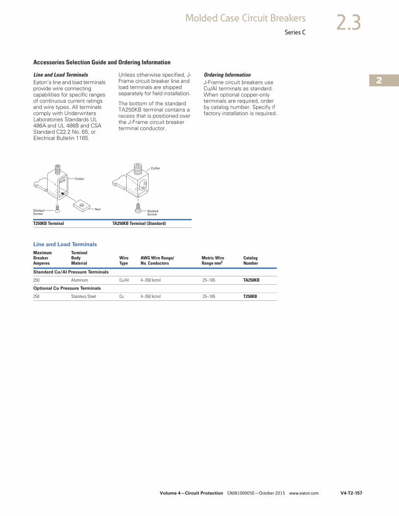
Volume 4—Circuit Protection CA08100005E—October 2015 www.eaton.com V4-T2-157
2
2
2
2
2
2
2
2
2
2
2
2
2
2
2
2
2
2
2
2
2
2
2
2
2
2
2
2
2
2
2.3Molded Case Circuit Breakers
Series C
Accessories Selection Guide and Ordering Information
Line and Load TerminalsEaton’s line and load terminals provide wire connecting capabilities for specific ranges of continuous current ratings and wire types. All terminals comply with Underwriters Laboratories Standards UL 486A and UL 486B and CSA Standard C22.2 No. 65, or Electrical Bulletin 1165.
Unless otherwise specified, J-Frame circuit breaker line and load terminals are shipped separately for field installation.
The bottom of the standard TA250KB terminal contains a recess that is positioned over the J-Frame circuit breaker terminal conductor.
Ordering InformationJ-Frame circuit breakers use Cu/AI terminals as standard. When optional copper-only terminals are required, order by catalog number. Specify if factory installation is required.
Line and Load Terminals
T250KB Terminal TA250KB Terminal (Standard)
MaximumBreakerAmperes
TerminalBodyMaterial
Wire Type
AWG Wire Range/No. Conductors
Metric WireRange mm2
CatalogNumber
Standard Cu/AI Pressure Terminals
250 Aluminum Cu/AI 4–350 kcmil 25–185 TA250KB
Optional Cu Pressure Terminals
250 Stainless Steel Cu 4–350 kcmil 25–185 T250KB
NutSlottedScrew
Collar
Collar
SlottedScrew
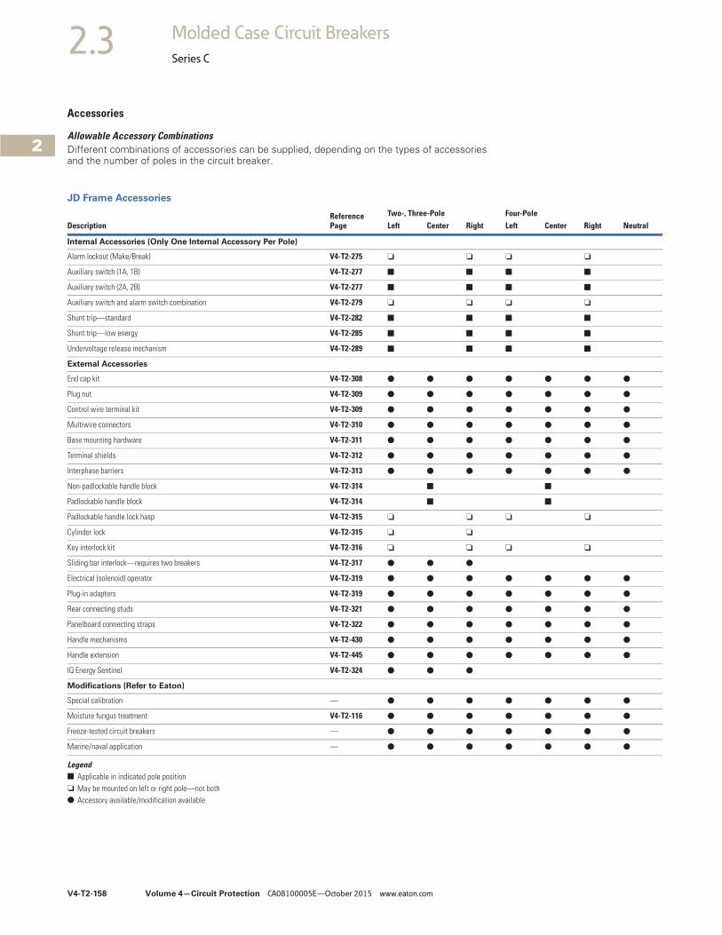
V4-T2-158 Volume 4—Circuit Protection CA08100005E—October 2015 www.eaton.com
2
2
2
2
2
2
2
2
2
2
2
2
2
2
2
2
2
2
2
2
2
2
2
2
2
2
2
2
2
2
2.3 Molded Case Circuit Breakers
Series C
Accessories
Allowable Accessory CombinationsDifferent combinations of accessories can be supplied, depending on the types of accessories and the number of poles in the circuit breaker.
JD Frame Accessories
Legend■ Applicable in indicated pole position❏ May be mounted on left or right pole—not both● Accessory available/modification available
DescriptionReference Page
Two-, Three-Pole Four-PoleLeft Center Right Left Center Right Neutral
Internal Accessories (Only One Internal Accessory Per Pole)
Alarm lockout (Make/Break) V4-T2-275 ❏ ❏ ❏ ❏
Auxiliary switch (1A, 1B) V4-T2-277 ■ ■ ■ ■
Auxiliary switch (2A, 2B) V4-T2-277 ■ ■ ■ ■
Auxiliary switch and alarm switch combination V4-T2-279 ❏ ❏ ❏ ❏
Shunt trip—standard V4-T2-282 ■ ■ ■ ■
Shunt trip—low energy V4-T2-285 ■ ■ ■ ■
Undervoltage release mechanism V4-T2-289 ■ ■ ■ ■
External Accessories
End cap kit V4-T2-308 ● ● ● ● ● ● ●
Plug nut V4-T2-309 ● ● ● ● ● ● ●
Control wire terminal kit V4-T2-309 ● ● ● ● ● ● ●
Multiwire connectors V4-T2-310 ● ● ● ● ● ● ●
Base mounting hardware V4-T2-311 ● ● ● ● ● ● ●
Terminal shields V4-T2-312 ● ● ● ● ● ● ●
Interphase barriers V4-T2-313 ● ● ● ● ● ● ●
Non-padlockable handle block V4-T2-314 ■ ■
Padlockable handle block V4-T2-314 ■ ■
Padlockable handle lock hasp V4-T2-315 ❏ ❏ ❏ ❏
Cylinder lock V4-T2-315 ❏ ❏
Key interlock kit V4-T2-316 ❏ ❏ ❏ ❏
Sliding bar interlock—requires two breakers V4-T2-317 ● ● ●
Electrical (solenoid) operator V4-T2-319 ● ● ● ● ● ● ●
Plug-in adapters V4-T2-319 ● ● ● ● ● ● ●
Rear connecting studs V4-T2-321 ● ● ● ● ● ● ●
Panelboard connecting straps V4-T2-322 ● ● ● ● ● ● ●
Handle mechanisms V4-T2-430 ● ● ● ● ● ● ●
Handle extension V4-T2-445 ● ● ● ● ● ● ●
IQ Energy Sentinel V4-T2-324 ● ● ●
Modifications (Refer to Eaton)
Special calibration — ● ● ● ● ● ● ●
Moisture fungus treatment V4-T2-116 ● ● ● ● ● ● ●
Freeze-tested circuit breakers — ● ● ● ● ● ● ●
Marine/naval application — ● ● ● ● ● ● ●
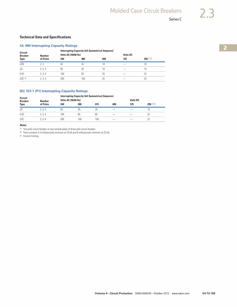
Volume 4—Circuit Protection CA08100005E—October 2015 www.eaton.com V4-T2-159
2
2
2
2
2
2
2
2
2
2
2
2
2
2
2
2
2
2
2
2
2
2
2
2
2
2
2
2
2
2
2.3Molded Case Circuit Breakers
Series C
Technical Data and Specifications
UL 489 Interrupting Capacity Ratings
IEC 157-1 (P1) Interrupting Capacity Ratings
Notes1 Two-pole circuit breaker or two outside poles of three-pole circuit breaker.2 Time constant is 3 milliseconds minimum at 10 kA and 8 milliseconds minimum at 22 kA.3 Current limiting.
CircuitBreakerType
Number of Poles
Interrupting Capacity (kA Symmetrical Amperes)Volts AC (50/60 Hz) Volts DC240 480 600 125 250 12
JDB 2, 3 65 35 18 — 10
JD 2, 3, 4 65 35 18 — 10
HJD 2, 3, 4 100 65 25 — 22
JDC 3 2, 3, 4 200 100 35 — 22
CircuitBreakerType
Number of Poles
Interrupting Capacity (kA Symmetrical Amperes)Volts AC (50/60 Hz) Volts DC240 380 415 600 125 250 12
JD 2, 3, 4 65 35 35 — — 10
HJD 2, 3, 4 100 65 65 — — 22
JDC 2, 3, 4 200 100 100 — — 22
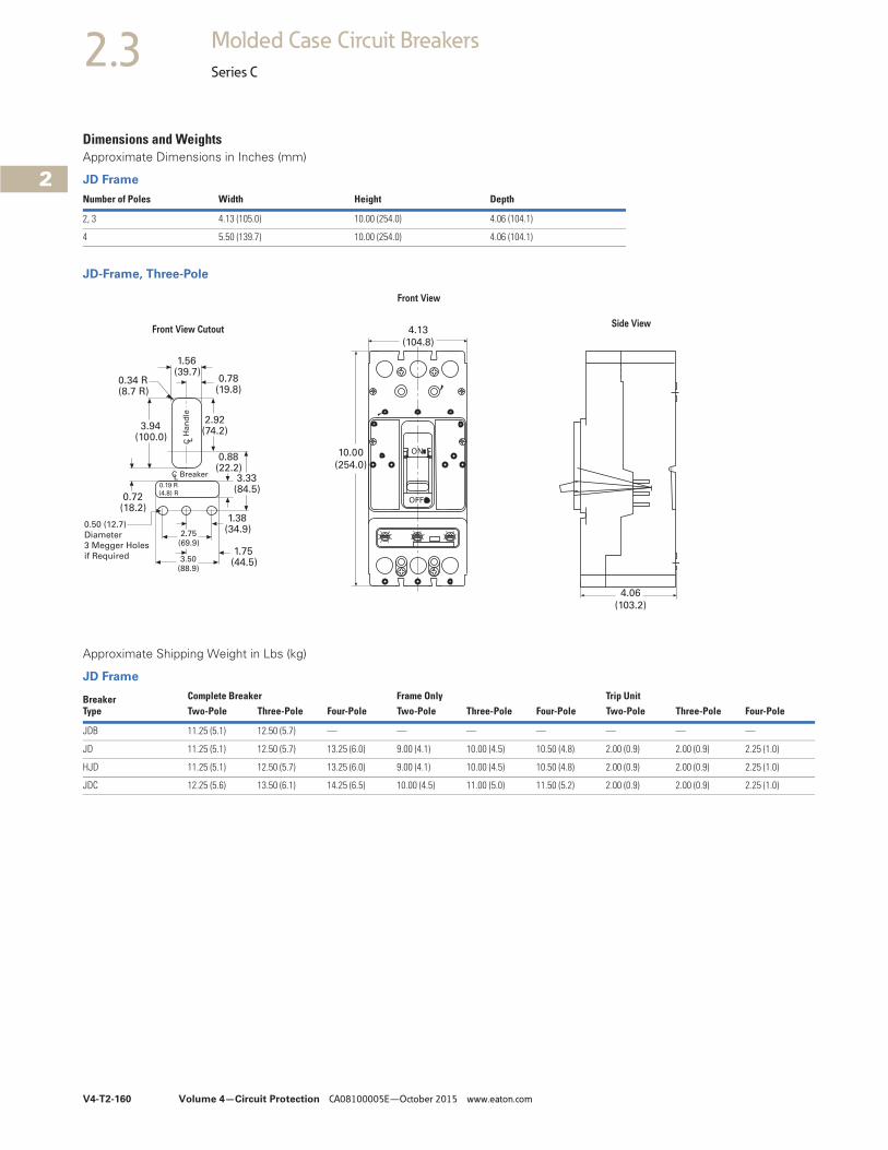
V4-T2-160 Volume 4—Circuit Protection CA08100005E—October 2015 www.eaton.com
2
2
2
2
2
2
2
2
2
2
2
2
2
2
2
2
2
2
2
2
2
2
2
2
2
2
2
2
2
2
2.3 Molded Case Circuit Breakers
Series C
Dimensions and WeightsApproximate Dimensions in Inches (mm)
JD Frame
JD-Frame, Three-Pole
Approximate Shipping Weight in Lbs (kg)
JD Frame
Number of Poles Width Height Depth
2, 3 4.13 (105.0) 10.00 (254.0) 4.06 (104.1)
4 5.50 (139.7) 10.00 (254.0) 4.06 (104.1)
4.13
(104.8)
10.00
(254.0)
ON
OFF
4.06
(103.2)
0.34 R(8.7 R)
1.56(39.7)
0.78(19.8)
3.94(100.0)
2.92(74.2)
0.88(22.2)
3.33(84.5)
0.72(18.2)
1.38(34.9)
1.75(44.5)
2.75(69.9)
3.50(88.9)
C LH
an
dle
BreakerCL
Front View
Side View
0.19 R
(4.8) R
0.50 (12.7)
Diameter
3 Megger Holes
if Required
Front View Cutout
Breaker Type
Complete Breaker Frame Only Trip Unit Two-Pole Three-Pole Four-Pole Two-Pole Three-Pole Four-Pole Two-Pole Three-Pole Four-Pole
JDB 11.25 (5.1) 12.50 (5.7) — — — — — — —
JD 11.25 (5.1) 12.50 (5.7) 13.25 (6.0) 9.00 (4.1) 10.00 (4.5) 10.50 (4.8) 2.00 (0.9) 2.00 (0.9) 2.25 (1.0)
HJD 11.25 (5.1) 12.50 (5.7) 13.25 (6.0) 9.00 (4.1) 10.00 (4.5) 10.50 (4.8) 2.00 (0.9) 2.00 (0.9) 2.25 (1.0)
JDC 12.25 (5.6) 13.50 (6.1) 14.25 (6.5) 10.00 (4.5) 11.00 (5.0) 11.50 (5.2) 2.00 (0.9) 2.00 (0.9) 2.25 (1.0)

Volume 4—Circuit Protection CA08100005E—October 2015 www.eaton.com V4-T2-161
2
2
2
2
2
2
2
2
2
2
2
2
2
2
2
2
2
2
2
2
2
2
2
2
2
2
2
2
2
2
2.3Molded Case Circuit Breakers
Series C
Typical K-Frame Circuit Breaker ContentsDescription Page
Product Overview . . . . . . . . . . . . . . . . . . . . . . . . . . V4-T2-116
Standards and Certifications . . . . . . . . . . . . . . . . . . V4-T2-117
Quick Reference . . . . . . . . . . . . . . . . . . . . . . . . . . . V4-T2-118
G-Frame (15–100 Amperes) . . . . . . . . . . . . . . . . . . . V4-T2-121
F-Frame (10–225 Amperes) . . . . . . . . . . . . . . . . . . . V4-T2-135
J-Frame (70–250 Amperes) . . . . . . . . . . . . . . . . . . . V4-T2-153
K-Frame (70–400 Amperes)Catalog Number Selection . . . . . . . . . . . . . . . . . V4-T2-162
Product Selection . . . . . . . . . . . . . . . . . . . . . . . . V4-T2-164
Accessories . . . . . . . . . . . . . . . . . . . . . . . . . . . . V4-T2-180
Technical Data and Specifications. . . . . . . . . . . . V4-T2-181
Dimensions and Weights . . . . . . . . . . . . . . . . . . V4-T2-184
L-Frame (125–600 Amperes) . . . . . . . . . . . . . . . . . . V4-T2-185
M-Frame (300–800 Amperes) . . . . . . . . . . . . . . . . . V4-T2-211
N-Frame (400–1200 Amperes). . . . . . . . . . . . . . . . . V4-T2-222R-Frame (800–2500 Amperes) . . . . . . . . . . . . . . . . . V4-T2-237
Motor Circuit Protectors (MCP) . . . . . . . . . . . . . . . . V4-T2-256
Motor Protection Circuit Breakers (MPCB) . . . . . . . V4-T2-267
Type ELC Current Limiter Attachment (Size 0–4) . . . . . V4-T2-269
Current Limiting Circuit Breaker Module. . . . . . . . . . . V4-T2-270Internal Accessories. . . . . . . . . . . . . . . . . . . . . . . . . V4-T2-273External Accessories . . . . . . . . . . . . . . . . . . . . . . . . V4-T2-304
K-Frame (70–400 Amperes) Product Description● All Eaton K-Frame circuit
breakers are HACR rated● K-Frame circuit breakers are
available as individual components (frame, trip unit, terminals), or factory assembled complete breakers
● K-Frame circuit breakers with non-interchangeable trip units are suitable for reverse feed use

V4-T2-162 Volume 4—Circuit Protection CA08100005E—October 2015 www.eaton.com
2
2
2
2
2
2
2
2
2
2
2
2
2
2
2
2
2
2
2
2
2
2
2
2
2
2
2
2
2
2
2.3 Molded Case Circuit Breakers
Series C
Catalog Number SelectionThis information is presented only as an aid to understanding catalog numbers. It is not to be used to build catalog numbers for circuit breakers or trip units.
K-Frame with Thermal-Magnetic Trip Unit Technology
Thermal-Magnetic Breakers and Frames 1
Thermal-Magnetic Trip Unit 1
Notes1 Frames are the same for thermal-magnetic or 310+ electronic trip units, e.g., KD3400F or HKD3400F.
Ampere rating available with electronic trip unit only.
Numberof Poles
2 = Two-pole3 = Three-pole4 = Four-pole
Circuit Breaker/Frame Ampere
Rating100125150175200225250300350400
KD 3 400 F
Circuit Breaker/Frame Type
DKKDKDBHKDKDC
SuffixC = Copper terminalsE = 50% protected neutral pole (four-pole electronic
trip unit circuit breaker only)F = Frame only (400 A only)K = High-magnetic molded-case switchV = 50 ° calibration (thermal-magnetic trip units only)W = Without terminalsX = Load terminals onlyY = Line side terminals onlyBlank = Standard load and line side terminals
Numberof Poles
2 = Two-pole3 = Three-pole4 = Four-pole
Circuit Breaker/Frame Ampere
Rating100125150175200225250300350400
KT 3 400 F
Trip Unit TypeKT = Thermal-magnetic
SuffixT = Trip unit only
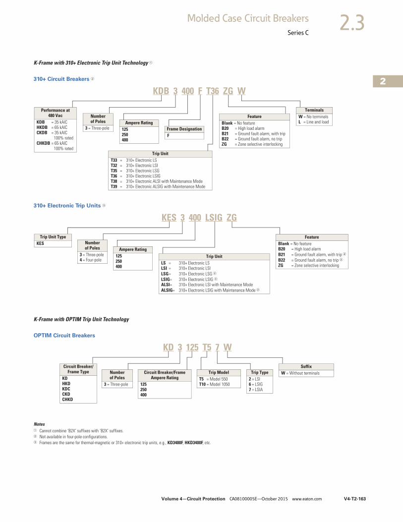
Volume 4—Circuit Protection CA08100005E—October 2015 www.eaton.com V4-T2-163
2
2
2
2
2
2
2
2
2
2
2
2
2
2
2
2
2
2
2
2
2
2
2
2
2
2
2
2
2
2
2.3Molded Case Circuit Breakers
Series C
K-Frame with 310+ Electronic Trip Unit Technology 1
310+ Circuit Breakers 2
310+ Electronic Trip Units 3
K-Frame with OPTIM Trip Unit Technology
OPTIM Circuit Breakers
Notes1 Cannot combine ‘B2X’ suffixes with ‘B2X’ suffixes.2 Not available in four-pole configurations.3 Frames are the same for thermal-magnetic or 310+ electronic trip units, e.g., KD3400F, HKD3400F, etc.
Performance at 480 Vac
KDB = 35 kAICHKDB = 65 kAICCKDB = 35 kAIC
100% ratedCHKDB = 65 kAIC
100% rated
Number of Poles
3 = Three-poleAmpere Rating
125250400
Trip UnitT33 = 310+ Electronic LST32 = 310+ Electronic LSIT35 = 310+ Electronic LSGT36 = 310+ Electronic LSIGT38 = 310+ Electronic ALSI with Maintenance ModeT39 = 310+ Electronic ALSIG with Maintenance Mode
FeatureBlank = No featureB20 = High load alarmB21 = Ground fault alarm, with tripB22 = Ground fault alarm, no tripZG = Zone selective interlocking
TerminalsW = No terminalsL = Line and load
Frame DesignationF
KDB 3 400 F T36 ZG W
Trip Unit TypeKES Number
of Poles3 = Three-pole4 = Four-pole
Ampere Rating125250400
Trip UnitLS = 310+ Electronic LSLSI = 310+ Electronic LSILSG= 310+ Electronic LSG 2LSIG= 310+ Electronic LSIG 2ALSI= 310+ Electronic LSI with Maintenance ModeALSIG= 310+ Electronic LSIG with Maintenance Mode 2
FeatureBlank = No featureB20 = High load alarmB21 = Ground fault alarm, with trip 2B22 = Ground fault alarm, no trip 2ZG = Zone selective interlocking
KES 3 400 LSIG ZG
Circuit Breaker/Frame Ampere Rating
125250400
Trip ModelT5 = Model 550T10 = Model 1050
KD 3 125 T5 7 W
Trip Type2 = LSI6 = LSIG7 = LSIA
SuffixW = Without terminals
Circuit Breaker/Frame Type
KDHKDKDCCKDCHKD
Numberof Poles
3 = Three-pole

V4-T2-164 Volume 4—Circuit Protection CA08100005E—October 2015 www.eaton.com
2
2
2
2
2
2
2
2
2
2
2
2
2
2
2
2
2
2
2
2
2
2
2
2
2
2
2
2
2
2
2.3 Molded Case Circuit Breakers
Series C
Product Selection
Types KD, HKD and KDC Thermal-Magnetic Circuit Breakers with Interchangeable Trip Units
Notes1 Magnetic trip adjustable 5–10 times continuous ampere rating.2 Individually packed.3 2TA400K, 3TA400K and 4TA400K terminal kits contain one terminal for each pole and one terminal cover.
MaximumContinuousAmpere Ratingat 40 °C
Standard InterruptingCapacity600 Vac Rated35 kAIC at 480 Vac
High Interrupting Capacity600 Vac Rated65 kAIC at 480 Vac
Ultra High InterruptingCapacity Current Limiting600 Vac Rated100 kAIC at 480 Vac
Thermal-MagneticTrip Unit Only 1
For Use with Standardor High or Ultra HighInterrupting Frames
Standard Terminals Only
See Page V4-T2-179 forOptional Terminals
Factory AssembledCircuit Consistingof Frame, Trip Unitand Terminals 1
Factory AssembledCircuit Consistingof Frame, Trip Unitand Terminals 1
Factory AssembledCircuit Consistingof Frame, Trip Unitand Terminals 1
CatalogNumber
CatalogNumber
CatalogNumber
CatalogNumber
CatalogNumber
Two-Pole
100 KD2100 HKD2100 KDC2100 KT2100T TA300K 2
125 KD2125 HKD2125 KDC2125 KT2125T TA300K 2
150 KD2150 HKD2150 KDC2150 KT2150T TA300K 2
175 KD2175 HKD2175 KDC2175 KT2175T TA300K 2
200 KD2200 HKD2200 KDC2200 KT2200T TA300K 2
225 KD2225 HKD2225 KDC2225 KT2225T TA300K 2
250 KD2250 HKD2250 KDC2250 KT2250T TA350K 2
300 KD2300 HKD2300 KDC2300 KT2300T TA350K 2
350 KD2350 HKD2350 KDC2350 KT2350T TA350K 2
400 KD2400 HKD2400 KDC2400 KT2400T 2TA400K 3
Three-Pole
100 KD3100 HKD3100 KDC3100 KT3100T TA300K 2
125 KD3125 HKD3125 KDC3125 KT3125T TA300K 2
150 KD3150 HKD3150 KDC3150 KT3150T TA300K 2
175 KD3175 HKD3175 KDC3175 KT3175T TA300K 2
200 KD3200 HKD3200 KDC3200 KT3200T TA300K 2
225 KD3225 HKD3225 KDC3225 KT3225T TA300K 2
250 KD3250 HKD3250 KDC3250 KT3250T TA350K 2
300 KD3300 HKD3300 KDC3300 KT3300T TA350K 2
350 KD3350 HKD3350 KDC3350 KT3350T TA350K 2
400 KD3400 HKD3400 KDC3400 KT3400T 3TA400K 3
Four-Pole
100 KD4100 HKD4100 KDC4100 KT3100T TA300K 2
125 KD4125 HKD4125 KDC4125 KT3125T TA300K 2
175 KD4175 HKD4175 KDC4175 KT3175T TA300K 2
200 KD4200 HKD4200 KDC4200 KT3200T TA300K 2
225 KD4225 HKD4225 KDC4225 KT3225T TA300K 2
250 KD4250 HKD4250 KDC4250 KT3250T TA350K 2
300 KD4300 HKD4300 KDC4300 KT3300T TA350K 2
350 KD4350 HKD4350 KDC4350 KT3350T TA350K 2
400 KD4400 HKD4400 KDC4400 KT3400T 4TA400K 3
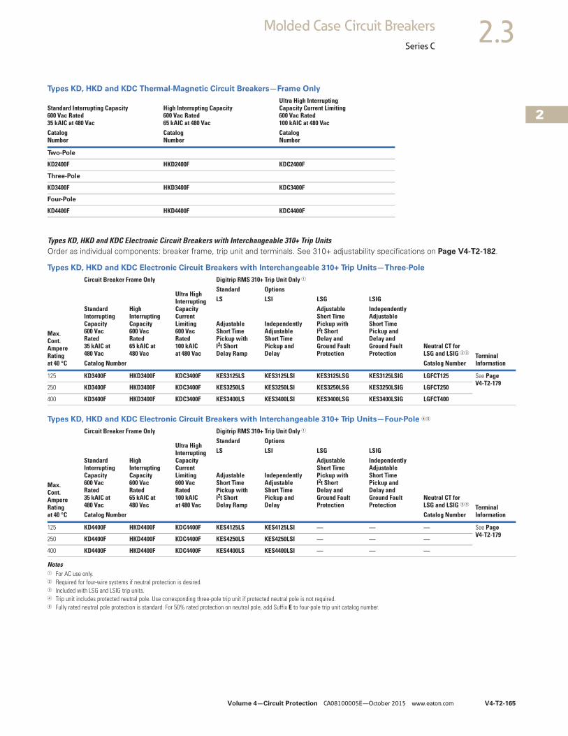
Volume 4—Circuit Protection CA08100005E—October 2015 www.eaton.com V4-T2-165
2
2
2
2
2
2
2
2
2
2
2
2
2
2
2
2
2
2
2
2
2
2
2
2
2
2
2
2
2
2
2.3Molded Case Circuit Breakers
Series C
Types KD, HKD and KDC Thermal-Magnetic Circuit Breakers—Frame Only
Types KD, HKD and KDC Electronic Circuit Breakers with Interchangeable 310+ Trip UnitsOrder as individual components: breaker frame, trip unit and terminals. See 310+ adjustability specifications on Page V4-T2-182.
Types KD, HKD and KDC Electronic Circuit Breakers with Interchangeable 310+ Trip Units—Three-Pole
Types KD, HKD and KDC Electronic Circuit Breakers with Interchangeable 310+ Trip Units—Four-Pole 45
Notes1 For AC use only.2 Required for four-wire systems if neutral protection is desired.3 Included with LSG and LSIG trip units.4 Trip unit includes protected neutral pole. Use corresponding three-pole trip unit if protected neutral pole is not required.5 Fully rated neutral pole protection is standard. For 50% rated protection on neutral pole, add Suffix E to four-pole trip unit catalog number.
Standard Interrupting Capacity600 Vac Rated35 kAIC at 480 Vac
High Interrupting Capacity600 Vac Rated65 kAIC at 480 Vac
Ultra High InterruptingCapacity Current Limiting600 Vac Rated100 kAIC at 480 Vac
CatalogNumber
CatalogNumber
CatalogNumber
Two-Pole
KD2400F HKD2400F KDC2400F
Three-Pole
KD3400F HKD3400F KDC3400F
Four-Pole
KD4400F HKD4400F KDC4400F
Max.Cont.AmpereRatingat 40 °C
Circuit Breaker Frame Only Digitrip RMS 310+ Trip Unit Only 1
Neutral CT forLSG and LSIG 23
Terminal Information
StandardInterruptingCapacity600 VacRated35 kAIC at480 Vac
HighInterruptingCapacity600 VacRated65 kAIC at480 Vac
Ultra HighInterruptingCapacityCurrentLimiting600 Vac Rated100 kAIC at 480 Vac
Standard OptionsLS LSI LSG LSIG
AdjustableShort TimePickup with I2t Short Delay Ramp
IndependentlyAdjustableShort TimePickup andDelay
AdjustableShort TimePickup withI2t ShortDelay andGround FaultProtection
IndependentlyAdjustableShort TimePickup andDelay andGround FaultProtection
Catalog Number Catalog Number
125 KD3400F HKD3400F KDC3400F KES3125LS KES3125LSI KES3125LSG KES3125LSIG LGFCT125 See Page V4-T2-179
250 KD3400F HKD3400F KDC3400F KES3250LS KES3250LSI KES3250LSG KES3250LSIG LGFCT250
400 KD3400F HKD3400F KDC3400F KES3400LS KES3400LSI KES3400LSG KES3400LSIG LGFCT400
Max.Cont.AmpereRatingat 40 °C
Circuit Breaker Frame Only Digitrip RMS 310+ Trip Unit Only 1
Neutral CT forLSG and LSIG 23
Terminal Information
StandardInterruptingCapacity600 VacRated35 kAIC at480 Vac
HighInterruptingCapacity600 VacRated65 kAIC at480 Vac
Ultra HighInterruptingCapacityCurrentLimiting600 Vac Rated100 kAIC at 480 Vac
Standard OptionsLS LSI LSG LSIG
AdjustableShort TimePickup with I2t Short Delay Ramp
IndependentlyAdjustableShort TimePickup andDelay
AdjustableShort TimePickup withI2t ShortDelay andGround FaultProtection
IndependentlyAdjustableShort TimePickup andDelay andGround FaultProtection
Catalog Number Catalog Number
125 KD4400F HKD4400F KDC4400F KES4125LS KES4125LSI — — — See Page V4-T2-179
250 KD4400F HKD4400F KDC4400F KES4250LS KES4250LSI — — —
400 KD4400F HKD4400F KDC4400F KES4400LS KES4400LSI — — —
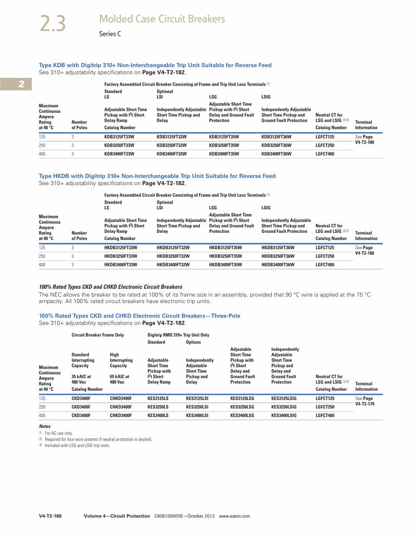
V4-T2-166 Volume 4—Circuit Protection CA08100005E—October 2015 www.eaton.com
2
2
2
2
2
2
2
2
2
2
2
2
2
2
2
2
2
2
2
2
2
2
2
2
2
2
2
2
2
2
2.3 Molded Case Circuit Breakers
Series C
Type KDB with Digitrip 310+ Non-Interchangeable Trip Unit Suitable for Reverse Feed
See 310+ adjustability specifications on Page V4-T2-182.
Type HKDB with Digitrip 310+ Non-Interchangeable Trip Unit Suitable for Reverse Feed
See 310+ adjustability specifications on Page V4-T2-182.
100% Rated Types CKD and CHKD Electronic Circuit BreakersThe NEC allows the breaker to be rated at 100% of its frame size in an assembly, provided that 90 °C wire is applied at the 75 °C ampacity. All 100% rated circuit breakers have electronic trip units.
100% Rated Types CKD and CHKD Electronic Circuit Breakers—Three-Pole
See 310+ adjustability specifications on Page V4-T2-182.
Notes1 For AC use only.2 Required for four-wire systems if neutral protection is desired.3 Included with LSG and LSIG trip units.
MaximumContinuousAmpereRatingat 40 °C
Numberof Poles
Factory Assembled Circuit Breaker Consisting of Frame and Trip Unit Less Terminals 1
Neutral CT forLSG and LSIG 23
Terminal Information
StandardLS
OptionalLSI LSG LSIG
Adjustable Short Time Pickup with I2t Short Delay Ramp
Independently Adjustable Short Time Pickup and Delay
Adjustable Short Time Pickup with I2t Short Delay and Ground Fault Protection
Independently Adjustable Short Time Pickup and Ground Fault Protection
Catalog Number Catalog Number
125 3 KDB3125FT33W KDB3125FT32W KDB3125FT35W KDB3125FT36W LGFCT125 See PageV4-T2-180
250 3 KDB3250FT33W KDB3250FT32W KDB3250FT35W KDB3250FT36W LGFCT250
400 3 KDB3400FT33W KDB3400FT32W KDB3400FT35W KDB3400FT36W LGFCT400
MaximumContinuousAmpereRatingat 40 °C
Numberof Poles
Factory Assembled Circuit Breaker Consisting of Frame and Trip Unit Less Terminals 1
Neutral CT forLSG and LSIG 23
Terminal Information
StandardLS
OptionalLSI LSG LSIG
Adjustable Short Time Pickup with I2t Short Delay Ramp
Independently Adjustable Short Time Pickup and Delay
Adjustable Short Time Pickup with I2t Short Delay and Ground Fault Protection
Independently Adjustable Short Time Pickup and Ground Fault Protection
Catalog Number Catalog Number
125 3 HKDB3125FT33W HKDB3125FT32W HKDB3125FT35W HKDB3125FT36W LGFCT125 See PageV4-T2-180
250 3 HKDB3250FT33W HKDB3250FT32W HKDB3250FT35W HKDB3250FT36W LGFCT250
400 3 HKDB3400FT33W HKDB3400FT32W HKDB3400FT35W HKDB3400FT36W LGFCT400
MaximumContinuousAmpereRatingat 40 °C
Circuit Breaker Frame Only Digitrip RMS 310+ Trip Unit Only
Neutral CT forLSG and LSIG 23
Terminal Information
Standard InterruptingCapacity
35 kAIC at480 Vac
High InterruptingCapacity
65 kAIC at480 Vac
Standard Options
Adjustable Short Time Pickup withI2t Short Delay Ramp
IndependentlyAdjustableShort TimePickup andDelay
AdjustableShort TimePickup withI2t ShortDelay andGround FaultProtection
IndependentlyAdjustableShort TimePickup andDelay andGround FaultProtection
Catalog Number Catalog Number
125 CKD3400F CHKD3400F KES3125LS KES3125LSI KES3125LSG KES3125LSIG LGFCT125 See Page V4-T2-179
250 CKD3400F CHKD3400F KES3250LS KES3250LSI KES3250LSG KES3250LSIG LGFCT250
400 CKD3400F CHKD3400F KES3400LS KES3400LSI KES3400LSG KES3400LSIG LGFCT400
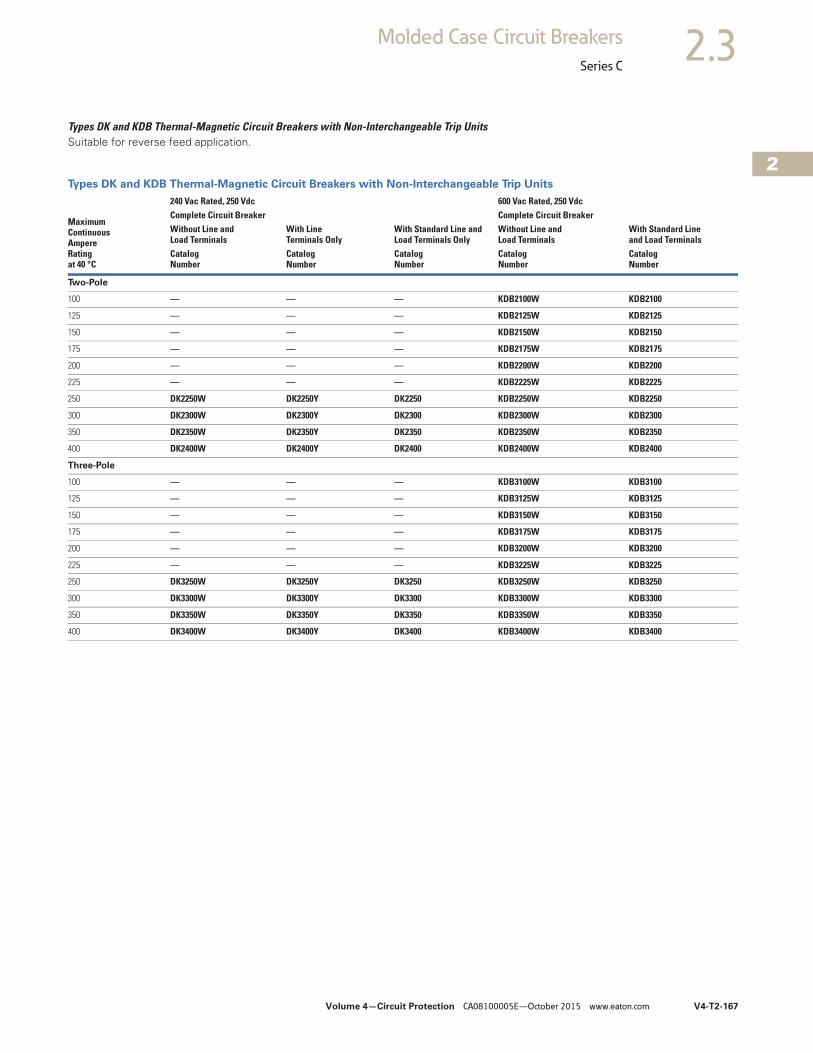
Volume 4—Circuit Protection CA08100005E—October 2015 www.eaton.com V4-T2-167
2
2
2
2
2
2
2
2
2
2
2
2
2
2
2
2
2
2
2
2
2
2
2
2
2
2
2
2
2
2
2.3Molded Case Circuit Breakers
Series C
Types DK and KDB Thermal-Magnetic Circuit Breakers with Non-Interchangeable Trip UnitsSuitable for reverse feed application.
Types DK and KDB Thermal-Magnetic Circuit Breakers with Non-Interchangeable Trip Units
MaximumContinuousAmpereRatingat 40 °C
240 Vac Rated, 250 Vdc 600 Vac Rated, 250 VdcComplete Circuit Breaker Complete Circuit BreakerWithout Line and Load Terminals
With Line Terminals Only
With Standard Line andLoad Terminals Only
Without Line andLoad Terminals
With Standard Lineand Load Terminals
CatalogNumber
CatalogNumber
CatalogNumber
CatalogNumber
CatalogNumber
Two-Pole
100 — — — KDB2100W KDB2100
125 — — — KDB2125W KDB2125
150 — — — KDB2150W KDB2150
175 — — — KDB2175W KDB2175
200 — — — KDB2200W KDB2200
225 — — — KDB2225W KDB2225
250 DK2250W DK2250Y DK2250 KDB2250W KDB2250
300 DK2300W DK2300Y DK2300 KDB2300W KDB2300
350 DK2350W DK2350Y DK2350 KDB2350W KDB2350
400 DK2400W DK2400Y DK2400 KDB2400W KDB2400
Three-Pole
100 — — — KDB3100W KDB3100
125 — — — KDB3125W KDB3125
150 — — — KDB3150W KDB3150
175 — — — KDB3175W KDB3175
200 — — — KDB3200W KDB3200
225 — — — KDB3225W KDB3225
250 DK3250W DK3250Y DK3250 KDB3250W KDB3250
300 DK3300W DK3300Y DK3300 KDB3300W KDB3300
350 DK3350W DK3350Y DK3350 KDB3350W KDB3350
400 DK3400W DK3400Y DK3400 KDB3400W KDB3400
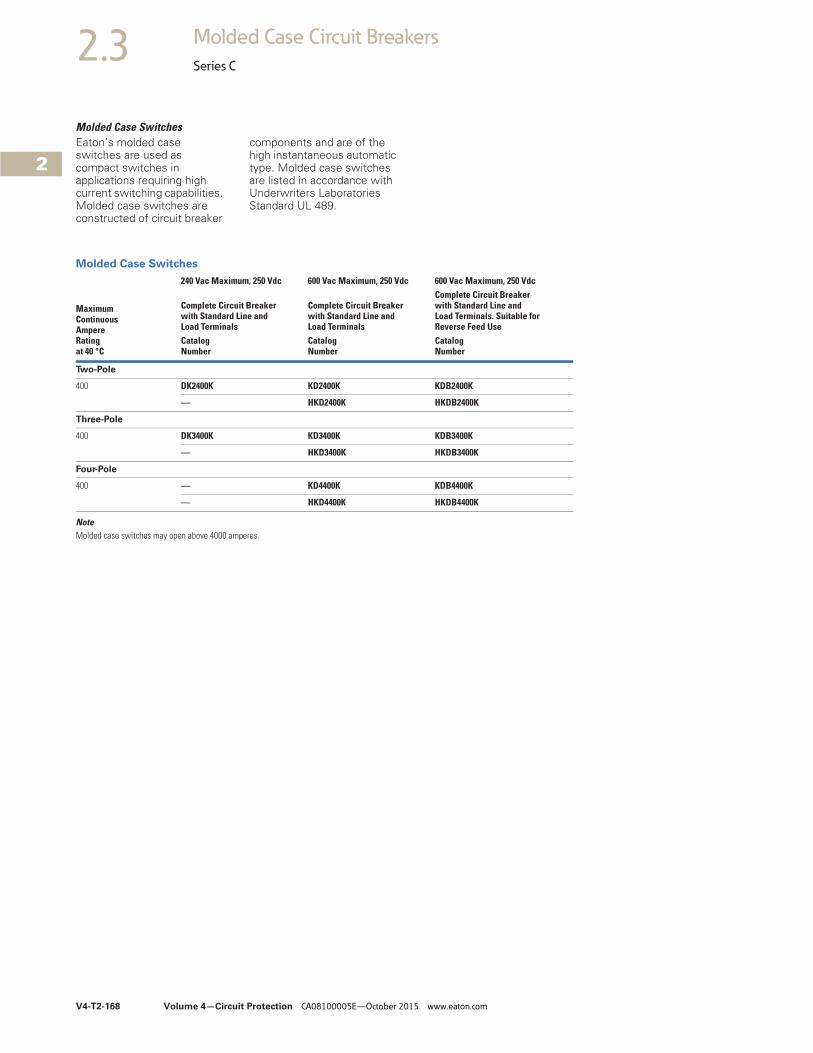
V4-T2-168 Volume 4—Circuit Protection CA08100005E—October 2015 www.eaton.com
2
2
2
2
2
2
2
2
2
2
2
2
2
2
2
2
2
2
2
2
2
2
2
2
2
2
2
2
2
2
2.3 Molded Case Circuit Breakers
Series C
Molded Case SwitchesEaton’s molded case switches are used as compact switches in applications requiring high current switching capabilities. Molded case switches are constructed of circuit breaker
components and are of the high instantaneous automatic type. Molded case switches are listed in accordance with Underwriters Laboratories Standard UL 489.
Molded Case Switches
NoteMolded case switches may open above 4000 amperes.
MaximumContinuous AmpereRatingat 40 °C
240 Vac Maximum, 250 Vdc 600 Vac Maximum, 250 Vdc 600 Vac Maximum, 250 Vdc
Complete Circuit Breakerwith Standard Line andLoad Terminals
Complete Circuit Breakerwith Standard Line andLoad Terminals
Complete Circuit Breakerwith Standard Line andLoad Terminals. Suitable forReverse Feed Use
CatalogNumber
CatalogNumber
CatalogNumber
Two-Pole
400 DK2400K KD2400K KDB2400K
— HKD2400K HKDB2400K
Three-Pole
400 DK3400K KD3400K KDB3400K
— HKD3400K HKDB3400K
Four-Pole
400 — KD4400K KDB4400K
— HKD4400K HKDB4400K
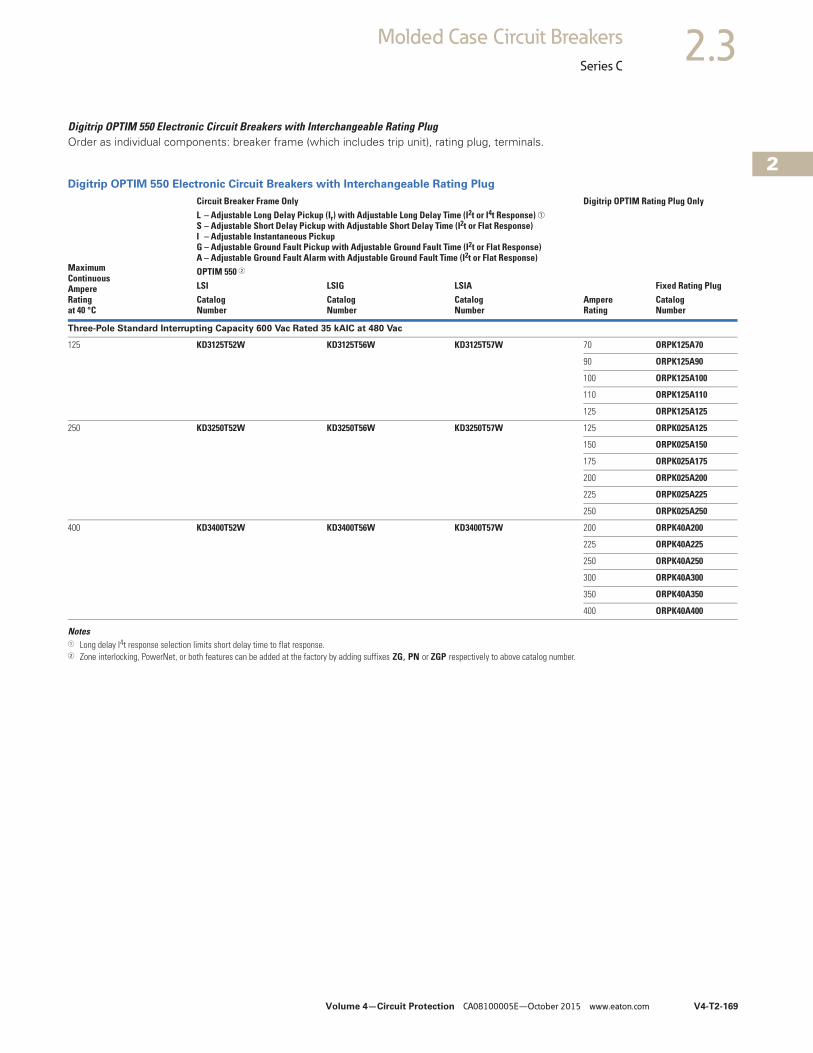
Volume 4—Circuit Protection CA08100005E—October 2015 www.eaton.com V4-T2-169
2
2
2
2
2
2
2
2
2
2
2
2
2
2
2
2
2
2
2
2
2
2
2
2
2
2
2
2
2
2
2.3Molded Case Circuit Breakers
Series C
Digitrip OPTIM 550 Electronic Circuit Breakers with Interchangeable Rating PlugOrder as individual components: breaker frame (which includes trip unit), rating plug, terminals.
Digitrip OPTIM 550 Electronic Circuit Breakers with Interchangeable Rating Plug
Notes1 Long delay I4t response selection limits short delay time to flat response.2 Zone interlocking, PowerNet, or both features can be added at the factory by adding suffixes ZG, PN or ZGP respectively to above catalog number.
MaximumContinuousAmpere Ratingat 40 °C
Circuit Breaker Frame Only Digitrip OPTIM Rating Plug OnlyL – Adjustable Long Delay Pickup (Ir) with Adjustable Long Delay Time (I2t or I4t Response) ➀S – Adjustable Short Delay Pickup with Adjustable Short Delay Time (I2t or Flat Response)I – Adjustable Instantaneous Pickup G – Adjustable Ground Fault Pickup with Adjustable Ground Fault Time (I2t or Flat Response)A – Adjustable Ground Fault Alarm with Adjustable Ground Fault Time (I2t or Flat Response)
AmpereRating
Fixed Rating PlugOPTIM 550 2
LSI LSIG LSIACatalogNumber
CatalogNumber
CatalogNumber
CatalogNumber
Three-Pole Standard Interrupting Capacity 600 Vac Rated 35 kAIC at 480 Vac
125 KD3125T52W KD3125T56W KD3125T57W 70 ORPK125A70
90 ORPK125A90
100 ORPK125A100
110 ORPK125A110
125 ORPK125A125
250 KD3250T52W KD3250T56W KD3250T57W 125 ORPK025A125
150 ORPK025A150
175 ORPK025A175
200 ORPK025A200
225 ORPK025A225
250 ORPK025A250
400 KD3400T52W KD3400T56W KD3400T57W 200 ORPK40A200
225 ORPK40A225
250 ORPK40A250
300 ORPK40A300
350 ORPK40A350
400 ORPK40A400
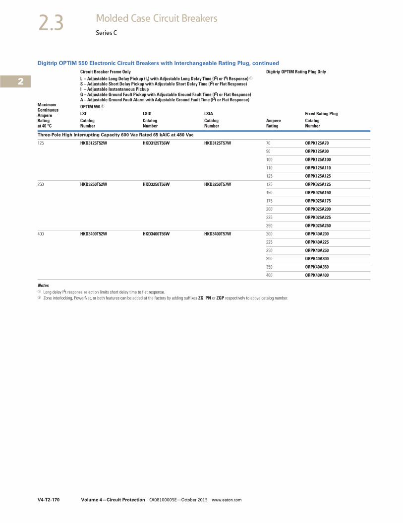
V4-T2-170 Volume 4—Circuit Protection CA08100005E—October 2015 www.eaton.com
2
2
2
2
2
2
2
2
2
2
2
2
2
2
2
2
2
2
2
2
2
2
2
2
2
2
2
2
2
2
2.3 Molded Case Circuit Breakers
Series C
Digitrip OPTIM 550 Electronic Circuit Breakers with Interchangeable Rating Plug, continued
Notes1 Long delay I4t response selection limits short delay time to flat response.2 Zone interlocking, PowerNet, or both features can be added at the factory by adding suffixes ZG, PN or ZGP respectively to above catalog number.
MaximumContinuousAmpere Ratingat 40 °C
Circuit Breaker Frame Only Digitrip OPTIM Rating Plug OnlyL – Adjustable Long Delay Pickup (Ir) with Adjustable Long Delay Time (I2t or I4t Response) 1S – Adjustable Short Delay Pickup with Adjustable Short Delay Time (I2t or Flat Response)I – Adjustable Instantaneous Pickup G – Adjustable Ground Fault Pickup with Adjustable Ground Fault Time (I2t or Flat Response)A – Adjustable Ground Fault Alarm with Adjustable Ground Fault Time (I2t or Flat Response)
AmpereRating
Fixed Rating PlugOPTIM 550 2
LSI LSIG LSIACatalogNumber
CatalogNumber
CatalogNumber
CatalogNumber
Three-Pole High Interrupting Capacity 600 Vac Rated 65 kAIC at 480 Vac
125 HKD3125T52W HKD3125T56W HKD3125T57W 70 ORPK125A70
90 ORPK125A90
100 ORPK125A100
110 ORPK125A110
125 ORPK125A125
250 HKD3250T52W HKD3250T56W HKD3250T57W 125 ORPK025A125
150 ORPK025A150
175 ORPK025A175
200 ORPK025A200
225 ORPK025A225
250 ORPK025A250
400 HKD3400T52W HKD3400T56W HKD3400T57W 200 ORPK40A200
225 ORPK40A225
250 ORPK40A250
300 ORPK40A300
350 ORPK40A350
400 ORPK40A400
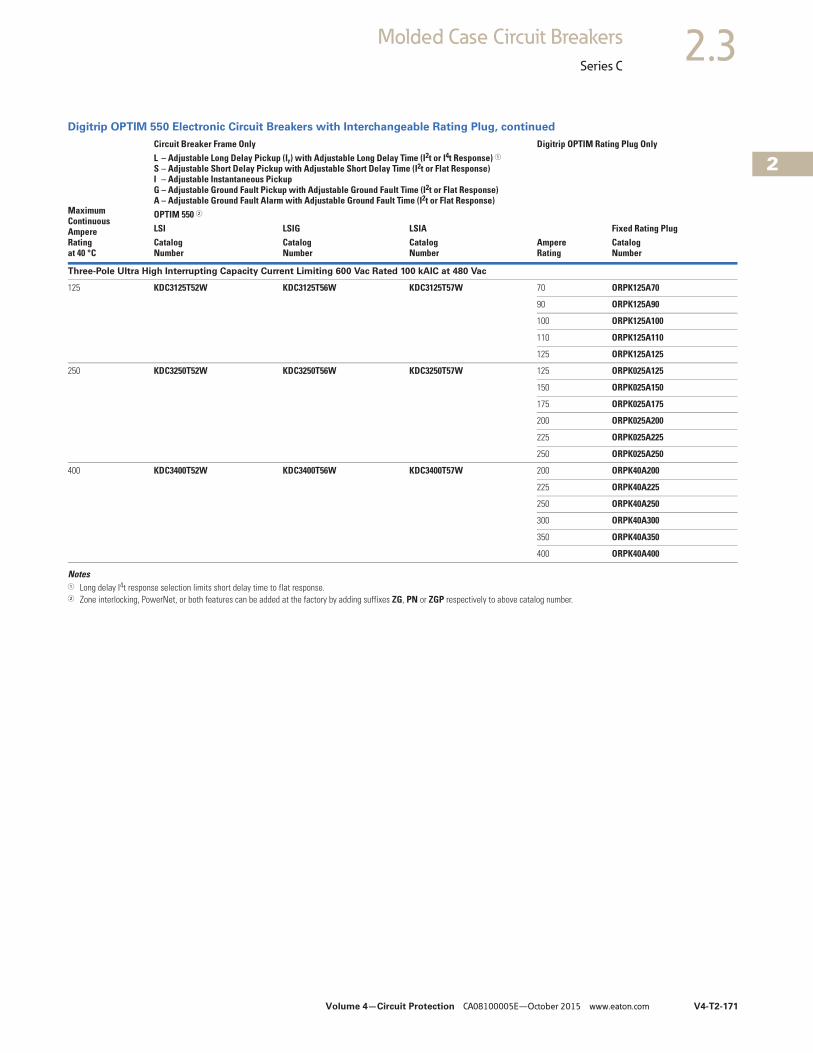
Volume 4—Circuit Protection CA08100005E—October 2015 www.eaton.com V4-T2-171
2
2
2
2
2
2
2
2
2
2
2
2
2
2
2
2
2
2
2
2
2
2
2
2
2
2
2
2
2
2
2.3Molded Case Circuit Breakers
Series C
Digitrip OPTIM 550 Electronic Circuit Breakers with Interchangeable Rating Plug, continued
Notes1 Long delay I4t response selection limits short delay time to flat response.2 Zone interlocking, PowerNet, or both features can be added at the factory by adding suffixes ZG, PN or ZGP respectively to above catalog number.
MaximumContinuousAmpere Ratingat 40 °C
Circuit Breaker Frame Only Digitrip OPTIM Rating Plug OnlyL – Adjustable Long Delay Pickup (Ir) with Adjustable Long Delay Time (I2t or I4t Response) 1S – Adjustable Short Delay Pickup with Adjustable Short Delay Time (I2t or Flat Response)I – Adjustable Instantaneous Pickup G – Adjustable Ground Fault Pickup with Adjustable Ground Fault Time (I2t or Flat Response)A – Adjustable Ground Fault Alarm with Adjustable Ground Fault Time (I2t or Flat Response)
AmpereRating
Fixed Rating PlugOPTIM 550 2
LSI LSIG LSIACatalogNumber
CatalogNumber
CatalogNumber
CatalogNumber
Three-Pole Ultra High Interrupting Capacity Current Limiting 600 Vac Rated 100 kAIC at 480 Vac
125 KDC3125T52W KDC3125T56W KDC3125T57W 70 ORPK125A70
90 ORPK125A90
100 ORPK125A100
110 ORPK125A110
125 ORPK125A125
250 KDC3250T52W KDC3250T56W KDC3250T57W 125 ORPK025A125
150 ORPK025A150
175 ORPK025A175
200 ORPK025A200
225 ORPK025A225
250 ORPK025A250
400 KDC3400T52W KDC3400T56W KDC3400T57W 200 ORPK40A200
225 ORPK40A225
250 ORPK40A250
300 ORPK40A300
350 ORPK40A350
400 ORPK40A400
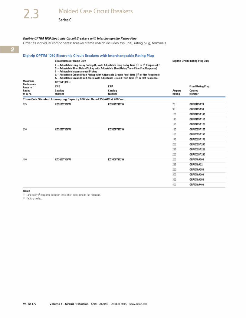
V4-T2-172 Volume 4—Circuit Protection CA08100005E—October 2015 www.eaton.com
2
2
2
2
2
2
2
2
2
2
2
2
2
2
2
2
2
2
2
2
2
2
2
2
2
2
2
2
2
2
2.3 Molded Case Circuit Breakers
Series C
Digitrip OPTIM 1050 Electronic Circuit Breakers with Interchangeable Rating PlugOrder as individual components: breaker frame (which includes trip unit), rating plug, terminals.
Digitrip OPTIM 1050 Electronic Circuit Breakers with Interchangeable Rating Plug
Notes1 Long delay I4t response selection limits short delay time to flat response.2 Factory sealed.
MaximumContinuousAmpereRatingat 40 °C
Circuit Breaker Frame Only Digitrip OPTIM Rating Plug OnlyL – Adjustable Long Delay Pickup (Ir) with Adjustable Long Delay Time (I2t or I4t Response) 1S – Adjustable Short Delay Pickup with Adjustable Short Delay Time (I2t or Flat Response)I – Adjustable Instantaneous Pickup G – Adjustable Ground Fault Pickup with Adjustable Ground Fault Time (I2t or Flat Response)A – Adjustable Ground Fault Alarm with Adjustable Ground Fault Time (I2t or Flat Response)
AmpereRating
Fixed Rating PlugOPTIM 1050 2
LSIG LSIACatalogNumber
CatalogNumber
CatalogNumber
Three-Pole Standard Interrupting Capacity 600 Vac Rated 35 kAIC at 480 Vac
125 KD3125T106W KD3125T107W 70 ORPK125A70
90 ORPK125A90
100 ORPK125A100
110 ORPK125A110
125 ORPK125A125
250 KD3250T106W KD3250T107W 125 ORPK025A125
150 ORPK025A150
175 ORPK025A175
200 ORPK025A200
225 ORPK025A225
250 ORPK025A250
400 KD3400T106W KD3400T107W 200 ORPK40A200
225 ORPK40A22
250 ORPK40A250
300 ORPK40A300
350 ORPK40A350
400 ORPK40A400
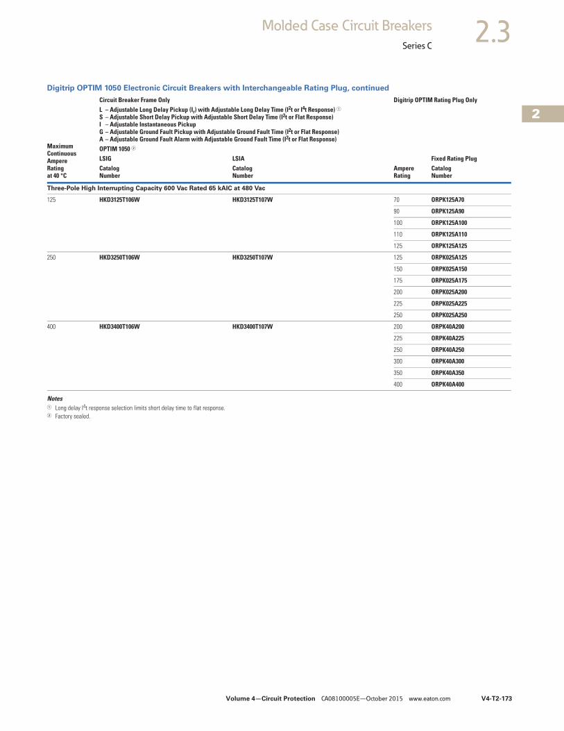
Volume 4—Circuit Protection CA08100005E—October 2015 www.eaton.com V4-T2-173
2
2
2
2
2
2
2
2
2
2
2
2
2
2
2
2
2
2
2
2
2
2
2
2
2
2
2
2
2
2
2.3Molded Case Circuit Breakers
Series C
Digitrip OPTIM 1050 Electronic Circuit Breakers with Interchangeable Rating Plug, continued
Notes1 Long delay I4t response selection limits short delay time to flat response.2 Factory sealed.
MaximumContinuousAmpereRatingat 40 °C
Circuit Breaker Frame Only Digitrip OPTIM Rating Plug OnlyL – Adjustable Long Delay Pickup (Ir) with Adjustable Long Delay Time (I2t or I4t Response) 1S – Adjustable Short Delay Pickup with Adjustable Short Delay Time (I2t or Flat Response)I – Adjustable Instantaneous Pickup G – Adjustable Ground Fault Pickup with Adjustable Ground Fault Time (I2t or Flat Response)A – Adjustable Ground Fault Alarm with Adjustable Ground Fault Time (I2t or Flat Response)
AmpereRating
Fixed Rating PlugOPTIM 1050 2
LSIG LSIACatalogNumber
CatalogNumber
CatalogNumber
Three-Pole High Interrupting Capacity 600 Vac Rated 65 kAIC at 480 Vac
125 HKD3125T106W HKD3125T107W 70 ORPK125A70
90 ORPK125A90
100 ORPK125A100
110 ORPK125A110
125 ORPK125A125
250 HKD3250T106W HKD3250T107W 125 ORPK025A125
150 ORPK025A150
175 ORPK025A175
200 ORPK025A200
225 ORPK025A225
250 ORPK025A250
400 HKD3400T106W HKD3400T107W 200 ORPK40A200
225 ORPK40A225
250 ORPK40A250
300 ORPK40A300
350 ORPK40A350
400 ORPK40A400
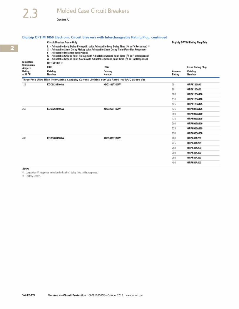
V4-T2-174 Volume 4—Circuit Protection CA08100005E—October 2015 www.eaton.com
2
2
2
2
2
2
2
2
2
2
2
2
2
2
2
2
2
2
2
2
2
2
2
2
2
2
2
2
2
2
2.3 Molded Case Circuit Breakers
Series C
Digitrip OPTIM 1050 Electronic Circuit Breakers with Interchangeable Rating Plug, continued
Notes1 Long delay I4t response selection limits short delay time to flat response.2 Factory sealed.
MaximumContinuousAmpereRatingat 40 °C
Circuit Breaker Frame Only Digitrip OPTIM Rating Plug OnlyL – Adjustable Long Delay Pickup (Ir) with Adjustable Long Delay Time (I2t or I4t Response) 1S – Adjustable Short Delay Pickup with Adjustable Short Delay Time (I2t or Flat Response)I – Adjustable Instantaneous Pickup G – Adjustable Ground Fault Pickup with Adjustable Ground Fault Time (I2t or Flat Response)A – Adjustable Ground Fault Alarm with Adjustable Ground Fault Time (I2t or Flat Response)
AmpereRating
Fixed Rating PlugOPTIM 1050 2
LSIG LSIACatalogNumber
CatalogNumber
CatalogNumber
Three-Pole Ultra High Interrupting Capacity Current Limiting 600 Vac Rated 100 kAIC at 480 Vac
125 KDC3125T106W KDC3125T107W 70 ORPK125A70
90 ORPK125A90
100 ORPK125A100
110 ORPK125A110
125 ORPK125A125
250 KDC3250T106W KDC3250T107W 125 ORPK025A125
150 ORPK025A150
175 ORPK025A175
200 ORPK025A200
225 ORPK025A225
250 ORPK025A250
400 KDC3400T106W KDC3400T107W 200 ORPK40A200
225 ORPK40A225
250 ORPK40A250
300 ORPK40A300
350 ORPK40A350
400 ORPK40A400

Volume 4—Circuit Protection CA08100005E—October 2015 www.eaton.com V4-T2-175
2
2
2
2
2
2
2
2
2
2
2
2
2
2
2
2
2
2
2
2
2
2
2
2
2
2
2
2
2
2
2.3Molded Case Circuit Breakers
Series C
100% Rated Digitrip OPTIM 550 Electronic Circuit Breakers with Interchangeable Rating PlugOrder as individual components: breaker frame (which includes trip unit), rating plug, terminals.
100% Rated Digitrip OPTIM 550 Electronic Circuit Breakers with Interchangeable Rating Plug
Notes1 Long delay I4t response selection limits short delay time to flat response.2 Zone interlocking, PowerNet, or both features can be added at the factory by adding suffixes ZG, PN or ZGP respectively to above catalog number
(refer to Page V4-T2-293).
MaximumContinuousAmpereRatingat 40 °C
Circuit Breaker Frame Only Digitrip OPTIM Rating Plug OnlyL – Adjustable Long Delay Pickup (Ir) with Adjustable Long Delay Time (I2t or I4t Response) 1S – Adjustable Short Delay Pickup with Adjustable Short Delay Time (I2t or Flat Response)I – Adjustable Instantaneous Pickup G – Adjustable Ground Fault Pickup with Adjustable Ground Fault Time (I2t or Flat Response)A – Adjustable Ground Fault Alarm with Adjustable Ground Fault Time (I2t or Flat Response)
AmpereRating
Fixed Rating PlugOPTIM 550 2
LSI LSIG LSIACatalogNumber
CatalogNumber
CatalogNumber
CatalogNumber
Three-Pole Standard Interrupting Capacity 600 Vac Rated 35 kAIC at 480 Vac
125 CKD3125T52W CKD3125T56W CKD3125T57W 70 ORPK125A70
90 ORPK125A90
100 ORPK125A100
110 ORPK125A110
125 ORPK125A125
250 CKD3250T52W CKD3250T56W CKD3250T57W 125 ORPK025A125
150 ORPK025A150
175 ORPK025A175
200 ORPK025A200
225 ORPK025A225
250 ORPK025A250
400 CKD3400T52W CKD3400T56W CKD3400T57W 200 ORPK40A200
225 ORPK40A225
250 ORPK40A250
300 ORPK40A300
350 ORPK40A350
400 ORPK40A400
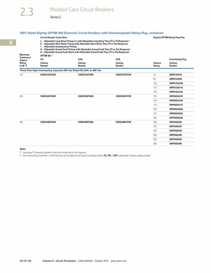
V4-T2-176 Volume 4—Circuit Protection CA08100005E—October 2015 www.eaton.com
2
2
2
2
2
2
2
2
2
2
2
2
2
2
2
2
2
2
2
2
2
2
2
2
2
2
2
2
2
2
2.3 Molded Case Circuit Breakers
Series C
100% Rated Digitrip OPTIM 550 Electronic Circuit Breakers with Interchangeable Rating Plug, continued
Notes1 Long delay I4t response selection limits short delay time to flat response.2 Zone interlocking, PowerNet, or both features can be added at the factory by adding suffixes ZG, PN or ZGP respectively to above catalog number.
MaximumContinuousAmpereRatingat 40 °C
Circuit Breaker Frame Only Digitrip OPTIM Rating Plug OnlyL – Adjustable Long Delay Pickup (Ir) with Adjustable Long Delay Time (I2t or I4t Response) 1S – Adjustable Short Delay Pickup with Adjustable Short Delay Time (I2t or Flat Response)I – Adjustable Instantaneous Pickup G – Adjustable Ground Fault Pickup with Adjustable Ground Fault Time (I2t or Flat Response)A – Adjustable Ground Fault Alarm with Adjustable Ground Fault Time (I2t or Flat Response)
AmpereRating
Fixed Rating PlugOPTIM 550 2
LSI LSIG LSIACatalogNumber
CatalogNumber
CatalogNumber
CatalogNumber
Three-Pole High Interrupting Capacity 600 Vac Rated 65 kAIC at 480 Vac
125 CHKD3125T52W CHKD3125T56W CHKD3125T57W 70 ORPK125A70
90 ORPK125A90
100 ORPK125A100
110 ORPK125A110
125 ORPK125A125
250 CHKD3250T52W CHKD3250T56W CHKD3250T57W 125 ORPK025A125
150 ORPK025A150
175 ORPK025A175
200 ORPK025A200
225 ORPK025A225
250 ORPK025A250
400 CHKD3400T52W CHKD3400T56W CHKD3400T57W 200 ORPK40A200
225 ORPK40A225
250 ORPK40A250
300 ORPK40A300
350 ORPK40A350
400 ORPK40A400
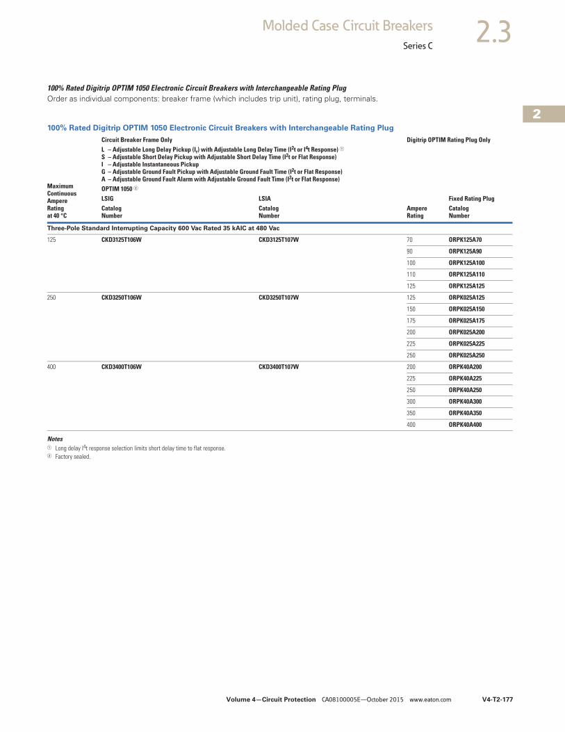
Volume 4—Circuit Protection CA08100005E—October 2015 www.eaton.com V4-T2-177
2
2
2
2
2
2
2
2
2
2
2
2
2
2
2
2
2
2
2
2
2
2
2
2
2
2
2
2
2
2
2.3Molded Case Circuit Breakers
Series C
100% Rated Digitrip OPTIM 1050 Electronic Circuit Breakers with Interchangeable Rating PlugOrder as individual components: breaker frame (which includes trip unit), rating plug, terminals.
100% Rated Digitrip OPTIM 1050 Electronic Circuit Breakers with Interchangeable Rating Plug
Notes1 Long delay I4t response selection limits short delay time to flat response.2 Factory sealed.
MaximumContinuousAmpereRatingat 40 °C
Circuit Breaker Frame Only Digitrip OPTIM Rating Plug OnlyL – Adjustable Long Delay Pickup (Ir) with Adjustable Long Delay Time (I2t or I4t Response) 1S – Adjustable Short Delay Pickup with Adjustable Short Delay Time (I2t or Flat Response)I – Adjustable Instantaneous Pickup G – Adjustable Ground Fault Pickup with Adjustable Ground Fault Time (I2t or Flat Response)A – Adjustable Ground Fault Alarm with Adjustable Ground Fault Time (I2t or Flat Response)
AmpereRating
Fixed Rating PlugOPTIM 1050 2
LSIG LSIACatalogNumber
CatalogNumber
CatalogNumber
Three-Pole Standard Interrupting Capacity 600 Vac Rated 35 kAIC at 480 Vac
125 CKD3125T106W CKD3125T107W 70 ORPK125A70
90 ORPK125A90
100 ORPK125A100
110 ORPK125A110
125 ORPK125A125
250 CKD3250T106W CKD3250T107W 125 ORPK025A125
150 ORPK025A150
175 ORPK025A175
200 ORPK025A200
225 ORPK025A225
250 ORPK025A250
400 CKD3400T106W CKD3400T107W 200 ORPK40A200
225 ORPK40A225
250 ORPK40A250
300 ORPK40A300
350 ORPK40A350
400 ORPK40A400
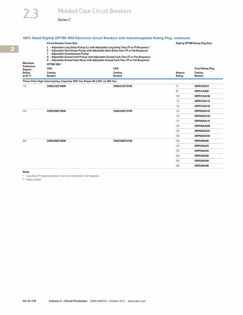
V4-T2-178 Volume 4—Circuit Protection CA08100005E—October 2015 www.eaton.com
2
2
2
2
2
2
2
2
2
2
2
2
2
2
2
2
2
2
2
2
2
2
2
2
2
2
2
2
2
2
2.3 Molded Case Circuit Breakers
Series C
100% Rated Digitrip OPTIM 1050 Electronic Circuit Breakers with Interchangeable Rating Plug, continued
Notes1 Long delay I4t response selection limits short delay time to flat response.2 Factory sealed.
MaximumContinuousAmpereRatingat 40 °C
Circuit Breaker Frame Only Digitrip OPTIM Rating Plug OnlyL – Adjustable Long Delay Pickup (Ir) with Adjustable Long Delay Time (I2t or I4t Response) 1S – Adjustable Short Delay Pickup with Adjustable Short Delay Time (I2t or Flat Response)I – Adjustable Instantaneous Pickup G – Adjustable Ground Fault Pickup with Adjustable Ground Fault Time (I2t or Flat Response)A – Adjustable Ground Fault Alarm with Adjustable Ground Fault Time (I2t or Flat Response)
AmpereRating
Fixed Rating PlugOPTIM 1050 2
LSIG LSIACatalogNumber
CatalogNumber
CatalogNumber
Three-Pole High Interrupting Capacity 600 Vac Rated 65 kAIC at 480 Vac
125 CHKD3125T106W CHKD3125T107W 70 ORPK125A70
90 ORPK125A90
100 ORPK125A100
110 ORPK125A110
125 ORPK125A125
250 CHKD3250T106W CHKD3250T107W 125 ORPK025A125
150 ORPK025A150
175 ORPK025A175
200 ORPK025A200
225 ORPK025A225
250 ORPK025A250
400 CHKD3400T106W CHKD3400T107W 200 ORPK40A200
225 ORPK40A225
250 ORPK40A250
300 ORPK40A300
350 ORPK40A350
400 ORPK40A400
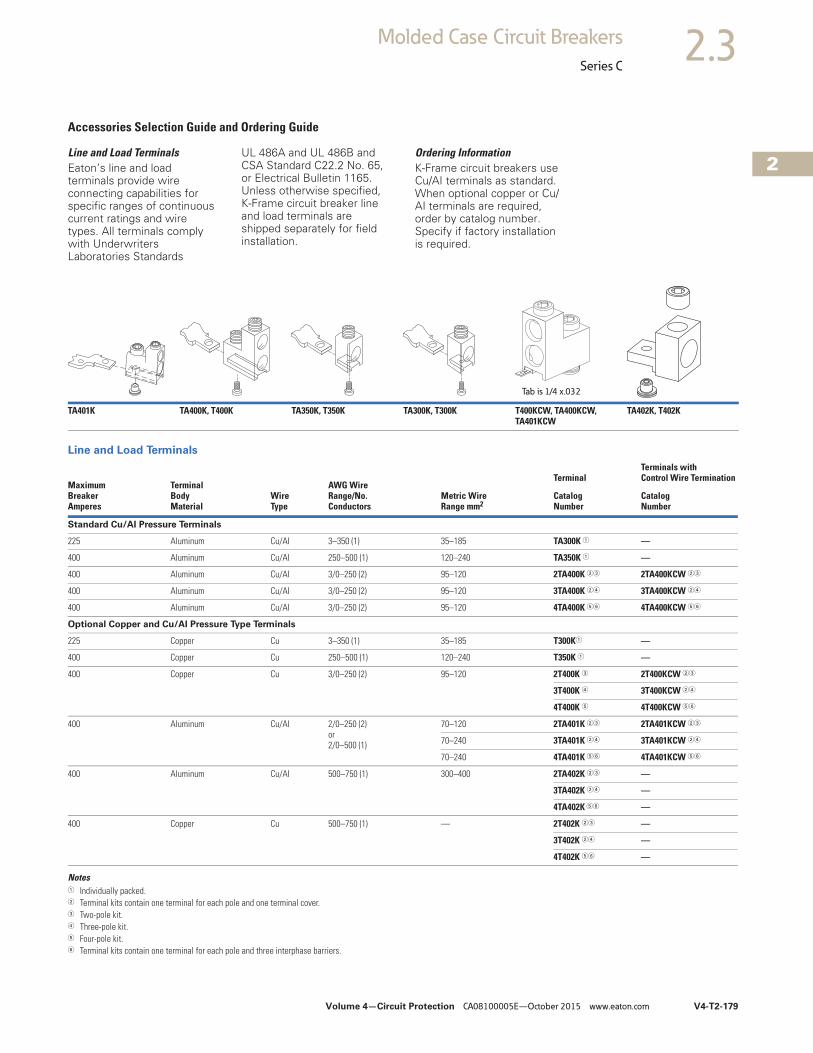
Volume 4—Circuit Protection CA08100005E—October 2015 www.eaton.com V4-T2-179
2
2
2
2
2
2
2
2
2
2
2
2
2
2
2
2
2
2
2
2
2
2
2
2
2
2
2
2
2
2
2.3Molded Case Circuit Breakers
Series C
Accessories Selection Guide and Ordering Guide
Line and Load TerminalsEaton’s line and load terminals provide wire connecting capabilities for specific ranges of continuous current ratings and wire types. All terminals comply with Underwriters Laboratories Standards
UL 486A and UL 486B and CSA Standard C22.2 No. 65, or Electrical Bulletin 1165. Unless otherwise specified, K-Frame circuit breaker line and load terminals are shipped separately for field installation.
Ordering InformationK-Frame circuit breakers use Cu/AI terminals as standard. When optional copper or Cu/AI terminals are required, order by catalog number. Specify if factory installation is required.
Line and Load Terminals
Notes1 Individually packed.2 Terminal kits contain one terminal for each pole and one terminal cover.3 Two-pole kit.4 Three-pole kit.5 Four-pole kit.6 Terminal kits contain one terminal for each pole and three interphase barriers.
TA401K TA400K, T400K TA350K, T350K TA300K, T300K T400KCW, TA400KCW, TA401KCW
TA402K, T402K
MaximumBreaker Amperes
TerminalBodyMaterial
Wire Type
AWG WireRange/No. Conductors
Metric WireRange mm2
TerminalTerminals with Control Wire Termination
CatalogNumber
CatalogNumber
Standard Cu/AI Pressure Terminals
225 Aluminum Cu/AI 3–350 (1) 35–185 TA300K 1 —
400 Aluminum Cu/AI 250–500 (1) 120–240 TA350K 1 —
400 Aluminum Cu/AI 3/0–250 (2) 95–120 2TA400K 23 2TA400KCW 23
400 Aluminum Cu/AI 3/0–250 (2) 95–120 3TA400K 24 3TA400KCW 24
400 Aluminum Cu/AI 3/0–250 (2) 95–120 4TA400K 56 4TA400KCW 56
Optional Copper and Cu/AI Pressure Type Terminals
225 Copper Cu 3–350 (1) 35–185 T300K1 —
400 Copper Cu 250–500 (1) 120–240 T350K 1 —
400 Copper Cu 3/0–250 (2) 95–120 2T400K 3 2T400KCW 23
3T400K 4 3T400KCW 24
4T400K 5 4T400KCW 56
400 Aluminum Cu/AI 2/0–250 (2)or2/0–500 (1)
70–120 2TA401K 23 2TA401KCW 23
70–240 3TA401K 24 3TA401KCW 24
70–240 4TA401K 56 4TA401KCW 56
400 Aluminum Cu/AI 500–750 (1) 300–400 2TA402K 23 —
3TA402K 24 —
4TA402K 56 —
400 Copper Cu 500–750 (1) — 2T402K 23 —
3T402K 24 —
4T402K 56 —
Tab is 1/4 x.032
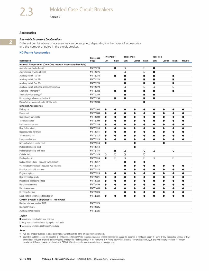
V4-T2-180 Volume 4—Circuit Protection CA08100005E—October 2015 www.eaton.com
2
2
2
2
2
2
2
2
2
2
2
2
2
2
2
2
2
2
2
2
2
2
2
2
2
2
2
2
2
2
2.3 Molded Case Circuit Breakers
Series C
Accessories
Allowable Accessory CombinationsDifferent combinations of accessories can be supplied, depending on the types of accessories and the number of poles in the circuit breaker.
KD Frame Accessories
Legend■ Applicable in indicated pole position❏ May be mounted on left or right pole—not both● Accessory available/modification available
Notes1 Two-pole breaker supplied in three-pole frame. Current carrying parts omitted from center pole.2 Shunt trip and UVR cannot be mounted in right poles on KES or OPTIM trip units. Standard internal accessories cannot be mounted in right pole on any K-Frame OPTIM trip unites. Special OPTIM
ground fault and zone interlock accessories are available for field installation in the right pole of K-Frame 550 OPTIM trip units. Factory installed 2a/2b and bell/aux are available for factory installation. K-Frame breakers equipped with OPTIM 1050 trip units include aux-bell alarm in the right pole.
DescriptionReference Page
Two-Pole 1 Three-Pole Four-Pole
Left Right Left Center Right Left Center Right Neutral
Internal Accessories (Only One Internal Accessory Per Pole)
Alarm lockout (Make/Break) V4-T2-276 ■ ❏ ❏ ■
Alarm lockout (2Make/2Break) V4-T2-276 ❏ ❏ ■
Auxiliary switch (1A, 1B) V4-T2-278 ■ ■ ■ ■ ■
Auxiliary switch (2A, 2B) V4-T2-278 ■ ■ ■ ■
Auxiliary switch (3A, 3B) V4-T2-278 ■ ■ ■ ■
Auxiliary switch and alarm switch combination V4-T2-279 ❏ ❏ ❏ ❏
Shunt trip—standard 2 V4-T2-282 ■ ■ ■ ■ ■
Shunt trip—low energy 2 V4-T2-285 ■ ■ ■
Undervoltage release mechanism 2 V4-T2-290 ■ ■ ■ ■
PowerNet or zone interlock kit (OPTIM 550) V4-T2-293 ■
External Accessories
End cap kit V4-T2-308 ● ● ● ● ● ● ● ● ●
Keeper nut V4-T2-308 ● ● ● ● ● ● ● ● ●
Control wire terminal kit V4-T2-309 ● ● ● ● ● ● ● ● ●
Terminal adapter V4-T2-309 ● ● ● ● ● ● ● ● ●
Multiwire connectors V4-T2-310 ● ● ● ● ● ● ● ● ●
Rear fed terminals V4-T2-310 ● ● ● ● ● ● ● ● ●
Base mounting hardware V4-T2-311 ● ● ● ● ● ● ● ● ●
Terminal shields V4-T2-313 ● ● ● ● ● ● ● ● ●
Interphase barriers V4-T2-313 ● ● ● ● ● ● ● ● ●
Non-padlockable handle block V4-T2-314 ■ ■ ■
Padlockable handle block V4-T2-314 ■
Padlockable handle lock hasp V4-T2-315 ■ ❏ ❏ ❏ ❏
Cylinder lock V4-T2-315 ❏ ❏ ❏ ❏
Key Interlock kit V4-T2-316 ■ ❏ ❏ ❏ ❏ ❏
Sliding bar interlock—requires two breakers V4-T2-317 ● ● ●
Walking beam interlock—requires two breakers V4-T2-317 ● ● ● ● ● ● ●
Electrical (solenoid) operator V4-T2-318 ● ● ● ● ● ● ●
Plug-in adapters V4-T2-319 ● ● ● ● ● ● ● ● ●
Rear connecting studs V4-T2-321 ● ● ● ● ● ● ● ● ●
Panelboard connecting straps V4-T2-322 ● ● ● ● ● ● ● ● ●
Handle mechanisms V4-T2-430 ● ● ● ● ● ● ● ● ●
Handle extension V4-T2-445 ● ● ● ● ● ● ● ● ●
IQ Energy Sentinel V4-T2-324 ● ● ● ● ● ● ●
Solid-state (electronic) portable test kit V4-T2-324 ● ● ● ● ● ● ● ● ●
OPTIM System Components Three Poles
Breaker interface module (BIM) V4-T2-325
Digitrip OPTIMizer V4-T2-325
Auxiliary power module V4-T2-325

Volume 4—Circuit Protection CA08100005E—October 2015 www.eaton.com V4-T2-181
2
2
2
2
2
2
2
2
2
2
2
2
2
2
2
2
2
2
2
2
2
2
2
2
2
2
2
2
2
2
2.3Molded Case Circuit Breakers
Series C
KD Frame Accessories, continued
Legend■ Applicable in indicated pole position❏ May be mounted on left or right pole—not both
● Accessory available/modification available
310+ Electronic Trip Unit Accessories
Technical Data and Specifications
NEMA/UL 489/CSA Interrupting Capacity Ratings
IEC 157-1 (P1) Interrupting Capacity Ratings
Notes1 Two-pole breaker supplied in three-pole frame. Current carrying parts omitted from center pole.2 MTST230V applies to 100–230 Vac.3 Included with all LD LSG and LSIG trip units and breakers.4 Includes 6 ft cable for remote mounting; NEMA 3R rated.5 Two-pole circuit breaker or two outside poles of three-pole circuit breaker.6 Time constant is 3 milliseconds minimum at 10 kA and 8 milliseconds minimum at 22 kA.7 Current limiting.
DescriptionReference Page
Two-Pole 1 Three-Pole Four-Pole
Left Right Left Center Right Left Center Right Neutral
Modifications (Refer to Eaton)
Special calibration — ● ● ● ● ● ● ● ● ●
Moisture fungus treatment V4-T2-116 ● ● ● ● ● ● ● ● ●
Freeze-tested circuit breakers — ● ● ● ● ● ● ● ● ●
Marine/naval application — ● ● ● ● ● ● ● ● ●
Description Catalog Number
Electronic portable test kit MTST230V 2
Trip unit tamper protection wire seal 5108A03H01
External neutral sensor, 400 A LGFCT400 3
External neutral sensor, 250 A LGFCT250 3
External neutral sensor, 125 A LGFCT125 3
Breaker-mount cause-of-trip indication TRIP-LED
Breaker-mount ammeter module DIGIVIEW
Remote-mount ammeter module DIGIVIEWR06 4
CircuitBreakerType
Numberof Poles
Interrupting Capacity (kA Symmetrical Amperes)
Volts AC (50/60 Hz) Volts DC
240 277 480 600 250 56
DK 2, 3 65 — — — 10
KDB 2, 3, 4 65 — 35 25 10
KD 2, 3, 4 65 — 35 25 10
HKD, HKDB 2, 3, 4 100 — 65 35 22
KDC 7 2, 3, 4 200 — 100 65 22
CKD 3 65 — 35 25 —
CHKD 3 100 — 65 35 —
CircuitBreakerType
Numberof Poles
Interrupting Capacity (kA Symmetrical Amperes)
Volts AC (50/60 Hz) Volts DC
240 380 415 440 500 600 250 56
DK 2, 3 65 — — — — — 10
KDB 2, 3, 4 65 40 40 — — — 10
KD 2, 3, 4 65 40 40 — — — 10
HKD, HKDB 2, 3, 4 100 65 65 — — — 22
KDC 2, 3, 4 200 100 100 — — — 22
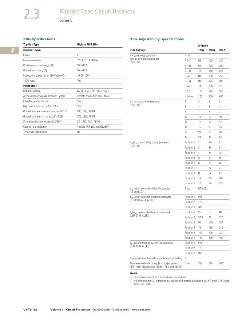
V4-T2-182 Volume 4—Circuit Protection CA08100005E—October 2015 www.eaton.com
2
2
2
2
2
2
2
2
2
2
2
2
2
2
2
2
2
2
2
2
2
2
2
2
2
2
2
2
2
2
2.3 Molded Case Circuit Breakers
Series C
310+ Specifications
Trip Unit Type Digitrip RMS 310+
Breaker Type
Frame K
Frames available 125 A, 250 A, 400 A
Continuous current range (A) 55–400 A
Ground fault pickup (A) 50–400 A
Interrupting capacities at 480 Vac (kAIC) 35, 65, 100
100% rated Yes
Protection
Ordering options LS, LSI, LSG, LSIG, ALSI, ALSIG
Arcflash Reduction Maintenance System Remote enabled on ALSI, ALSIG
Interchangeable trip unit Yes
High load alarm, trip (suffix B20) 1 Yes
Ground fault alarm with trip (suffix B21) 1 LSG, LSIG, ALSIG
Ground fault alarm, no trip (suffix B22) LSG, LSIG, ALSIG
Zone selective interlock (suffix ZG) 1 LSI, LSIG, ALSI, ALSIG
Cause of trip indication Yes (via TRIP-LED or DIGIVIEW)
Thru-cover accessories No
310+ Adjustability Specifications
Notes1 B2x suffixes cannot be combined with B2x suffixes.2 Not available for KD. Independently adjustable Ii setting available in LG, NG and RG ALSI and
ALSIG trip units.
K-Frame310+ Settings 125A 250 A 400 A
Ir = continuous current or long delay pickup (amperes) (All 310+)
Ir \ In
A (=Ir) 55 100 160
B (=Ir) 60 125 200
C (=Ir) 70 150 225
D (=Ir) 80 160 250
E (=Ir) 90 175 300
F (=Ir) 100 200 315
G (=Ir) 110 225 350
H (=Ir=In) 125 250 400
tr = long delay time (seconds)(All 310+)
2 2 2 2
4 4 4 4
7 7 7 7
10 10 10 10
12 12 12 12
15 15 15 15
20 20 20 20
24 24 24 24
Isd (x Ir) = short delay pickup (amperes)(All 310+)
Position 1 2 2x 2x
Position 2 3 3x 3x
Position 3 4 4x 4x
Position 4 5 5x 5x
Position 5 6 6x 6x
Position 6 7 7x 7x
Position 7 8 8x 8x
Position 8 10 10x 10x
Position 9 12 12x 12x
tsd = short delay time I2t (milliseconds)(LS and LSG)
Fixed 67 @10x
tsd = short delay time flat (milliseconds)(LSI, LSIG, ALSI, ALSIG)
Position 1 Inst
Position 2 120
Position 3 300
Ig (x In) = ground fault pickup (amperes)(LSG, LSIG, ALSIG)
Position 1 25 50 80
Position 2 37.5 75 120
Position 3 50 100 160
Position 4 75 150 240
Position 5 100 200 320
Position 6 125 250 400
tg = ground fault delay time (milliseconds)(LSG, LSIG, ALSIG)
Position 1 Inst
Position 2 120
Position 3 300
Independently adjustable Instantaneous (Ii) setting 2
Maintenance Mode pickup (2.5 x In) (amperes)(310+ with Maintenance Mode—ALSI and ALSIG)
Fixed 312 625 1000
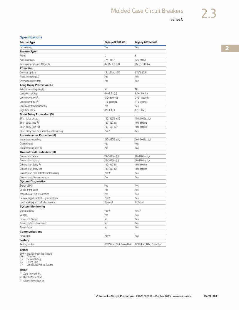
Volume 4—Circuit Protection CA08100005E—October 2015 www.eaton.com V4-T2-183
2
2
2
2
2
2
2
2
2
2
2
2
2
2
2
2
2
2
2
2
2
2
2
2
2
2
2
2
2
2
2.3Molded Case Circuit Breakers
Series C
Specifications
LegendBIM = Breaker Interface Module(A) = GF AlarmIs = Sensor RatingIn = Rating PlugIr = Long Delay Pickup Setting
Notes1 Zone interlock kit.2 By OPTIMizer/BIM.3 Eaton’s PowerNet kit.
Trip Unit Type Digitrip OPTIM 550 Digitrip OPTIM 1050
rms sensing Yes Yes
Breaker Type
Frame K K
Ampere range 125–400 A 125–400 A
Interrupting rating at 480 volts 35, 65, 100 (kA) 35, 65, 100 (kA)
Protection
Ordering options LSI, LSI(A), LSIG LSI(A), LSIG
Fixed rated plug (In) Yes Yes
Overtemperature trip Yes Yes
Long Delay Protection (L)
Adjustable rating plug (In) No No
Long delay pickup 0.4–1.0 x (In) 0.4–1.0 x (In)
Long delay time I2t 2–24 seconds 2–24 seconds
Long delay time I4t 1–5 seconds 1–5 seconds
Long delay thermal memory Yes Yes
High load alarm 0.5–1.0 x Ir 0.5–1.0 x IrShort Delay Protection (S)
Short delay pickup 150–800% x (Ir) 150–800% x (Ir)
Short delay time I2t 100–500 ms 100–500 ms
Short delay time flat 100–500 ms 100–500 ms
Short delay time zone selective interlocking Yes 1 Yes
Instantaneous Protection (I)
Instantaneous pickup 200–800% x (In) 200–800% x (In)
Discriminator Yes Yes
Instantaneous override Yes Yes
Ground Fault Protection (G)
Ground fault alarm 20–100% x (Is) 20–100% x (Is)
Ground fault pickup 20–100% x (Is) 20–100% x (Is)
Ground fault delay I2t 100–500 ms 100–500 ms
Ground fault delay flat 100–500 ms 100–500 ms
Ground fault zone selective interlocking Yes 1 Yes
Ground fault thermal memory Yes Yes
System Diagnostics
Status LEDs Yes Yes
Cause of trip LEDs Yes Yes
Magnitude of trip information Yes Yes
Remote signal contact—ground alarm Yes 1 Yes
Local auxiliary and bell alarm contact Optional Included
System Monitoring
Digital display Yes 2 Yes 2
Current Yes Yes
Power and energy No Yes
Power quality—harmonics No Yes
Power factor No Yes
Communications
PowerNet Yes 3 Yes
Testing
Testing method OPTIMizer, BIM, PowerNet OPTIMizer, BIM, PowerNet
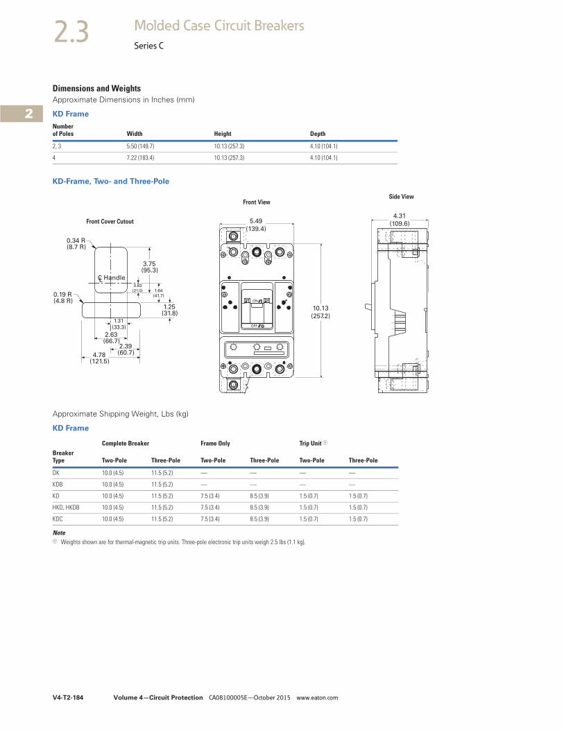
V4-T2-184 Volume 4—Circuit Protection CA08100005E—October 2015 www.eaton.com
2
2
2
2
2
2
2
2
2
2
2
2
2
2
2
2
2
2
2
2
2
2
2
2
2
2
2
2
2
2
2.3 Molded Case Circuit Breakers
Series C
Dimensions and WeightsApproximate Dimensions in Inches (mm)
KD Frame
KD-Frame, Two- and Three-Pole
Approximate Shipping Weight, Lbs (kg)
KD Frame
Note1 Weights shown are for thermal-magnetic trip units. Three-pole electronic trip units weigh 2.5 lbs (1.1 kg).
Numberof Poles Width Height Depth
2, 3 5.50 (149.7) 10.13 (257.3) 4.10 (104.1)
4 7.22 (183.4) 10.13 (257.3) 4.10 (104.1)
5.49
(139.4)
ON
OFF
10.13
(257.2)
4.31
(109.6)
0.34 R(8.7 R)
0.19 R(4.8 R)
3.75(95.3)
0.83
(21.0) 1.64(41.7)
1.25(31.8)
1.31
(33.3)
2.63(66.7)
2.39(60.7)4.78
(121.5)
CL Handle
Front ViewSide View
Front Cover Cutout
Complete Breaker Frame Only Trip Unit 1
BreakerType Two-Pole Three-Pole Two-Pole Three-Pole Two-Pole Three-Pole
DK 10.0 (4.5) 11.5 (5.2) — — — —
KDB 10.0 (4.5) 11.5 (5.2) — — — —
KD 10.0 (4.5) 11.5 (5.2) 7.5 (3.4) 8.5 (3.9) 1.5 (0.7) 1.5 (0.7)
HKD, HKDB 10.0 (4.5) 11.5 (5.2) 7.5 (3.4) 8.5 (3.9) 1.5 (0.7) 1.5 (0.7)
KDC 10.0 (4.5) 11.5 (5.2) 7.5 (3.4) 8.5 (3.9) 1.5 (0.7) 1.5 (0.7)
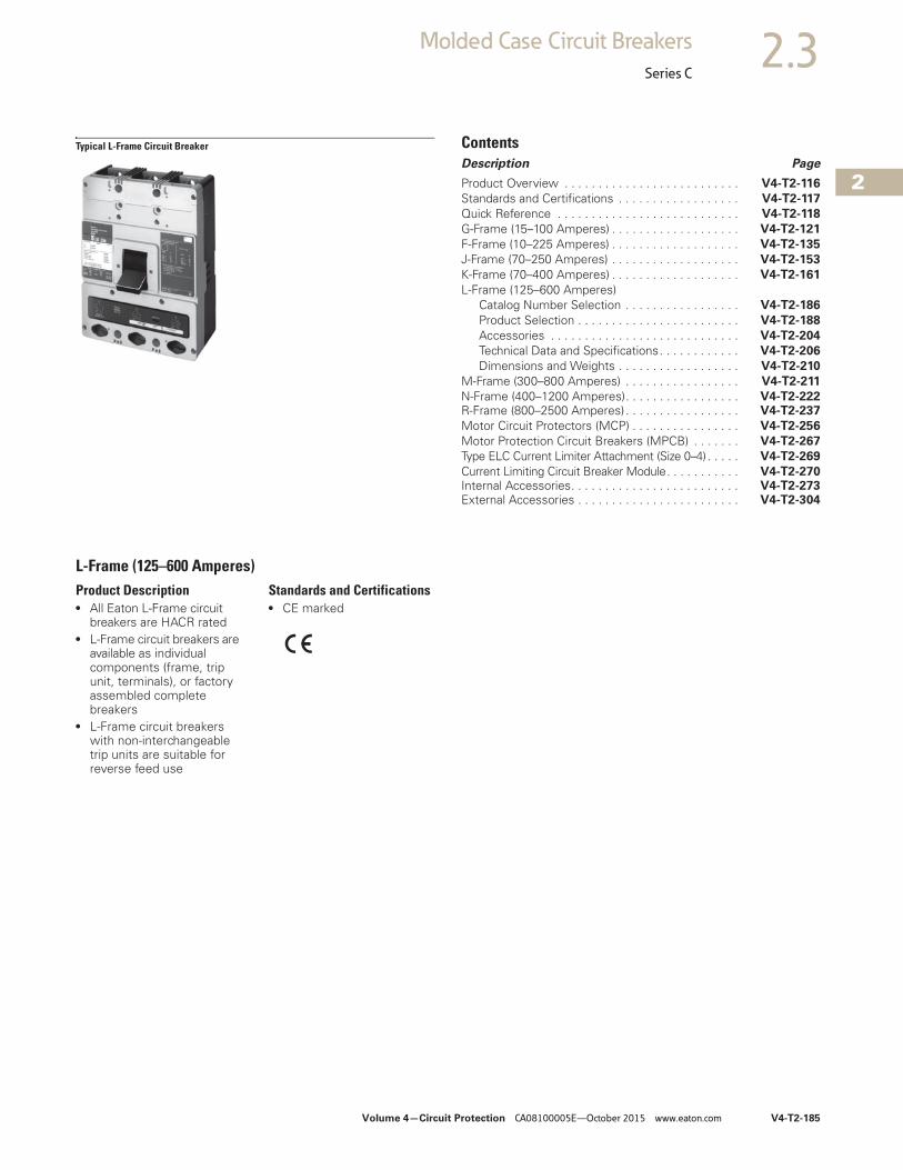
Volume 4—Circuit Protection CA08100005E—October 2015 www.eaton.com V4-T2-185
2
2
2
2
2
2
2
2
2
2
2
2
2
2
2
2
2
2
2
2
2
2
2
2
2
2
2
2
2
2
2.3Molded Case Circuit Breakers
Series C
Typical L-Frame Circuit Breaker ContentsDescription Page
Product Overview . . . . . . . . . . . . . . . . . . . . . . . . . . V4-T2-116
Standards and Certifications . . . . . . . . . . . . . . . . . . V4-T2-117
Quick Reference . . . . . . . . . . . . . . . . . . . . . . . . . . . V4-T2-118
G-Frame (15–100 Amperes) . . . . . . . . . . . . . . . . . . . V4-T2-121
F-Frame (10–225 Amperes) . . . . . . . . . . . . . . . . . . . V4-T2-135
J-Frame (70–250 Amperes) . . . . . . . . . . . . . . . . . . . V4-T2-153
K-Frame (70–400 Amperes) . . . . . . . . . . . . . . . . . . . V4-T2-161
L-Frame (125–600 Amperes)Catalog Number Selection . . . . . . . . . . . . . . . . . V4-T2-186
Product Selection . . . . . . . . . . . . . . . . . . . . . . . . V4-T2-188
Accessories . . . . . . . . . . . . . . . . . . . . . . . . . . . . V4-T2-204
Technical Data and Specifications. . . . . . . . . . . . V4-T2-206
Dimensions and Weights . . . . . . . . . . . . . . . . . . V4-T2-210
M-Frame (300–800 Amperes) . . . . . . . . . . . . . . . . . V4-T2-211
N-Frame (400–1200 Amperes). . . . . . . . . . . . . . . . . V4-T2-222R-Frame (800–2500 Amperes) . . . . . . . . . . . . . . . . . V4-T2-237
Motor Circuit Protectors (MCP) . . . . . . . . . . . . . . . . V4-T2-256
Motor Protection Circuit Breakers (MPCB) . . . . . . . V4-T2-267
Type ELC Current Limiter Attachment (Size 0–4) . . . . . V4-T2-269
Current Limiting Circuit Breaker Module. . . . . . . . . . . V4-T2-270Internal Accessories. . . . . . . . . . . . . . . . . . . . . . . . . V4-T2-273External Accessories . . . . . . . . . . . . . . . . . . . . . . . . V4-T2-304
L-Frame (125–600 Amperes)Product Description● All Eaton L-Frame circuit
breakers are HACR rated● L-Frame circuit breakers are
available as individual components (frame, trip unit, terminals), or factory assembled complete breakers
● L-Frame circuit breakers with non-interchangeable trip units are suitable for reverse feed use
Standards and Certifications● CE marked
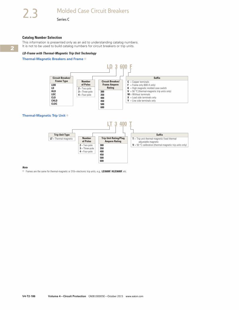
V4-T2-186 Volume 4—Circuit Protection CA08100005E—October 2015 www.eaton.com
2
2
2
2
2
2
2
2
2
2
2
2
2
2
2
2
2
2
2
2
2
2
2
2
2
2
2
2
2
2
2.3 Molded Case Circuit Breakers
Series C
Catalog Number SelectionThis information is presented only as an aid to understanding catalog numbers. It is not to be used to build catalog numbers for circuit breakers or trip units.
LD-Frame with Thermal-Magnetic Trip Unit Technology
Thermal-Magnetic Breakers and Frame 1
Thermal-Magnetic Trip Unit 1
Note1 Frames are the same for thermal-magnetic or 310+ electronic trip units, e.g., LD3600F, HLD3600F, etc.
LD 3 600 F
Circuit Breaker/Frame Type
LDBLDHLDLDCCLDCHLDCLDC
Number of Poles
2 = Two-pole3 = Three-pole4 = Four-pole
Circuit Breaker/Frame Ampere
Rating 300 350 400 450 500 600
SuffixC = Copper terminalsF = Frame only (600 A only)K = High magnetic molded case switchV = 50 °C (thermal-magnetic trip units only)W = Without terminalsX = Load side terminals onlyY = Line side terminals only
Number of Poles
2 = Two-pole3 = Three-pole4 = Four-pole
Trip Unit Rating/Plug Ampere Rating
300350400450500600
Trip Unit TypeLT = Thermal-magnetic
SuffixT = Trip unit thermal-magnetic fixed thermal
adjustable magneticV = 50 °C calibration (thermal-magnetic trip units only)
LT 3 400 T
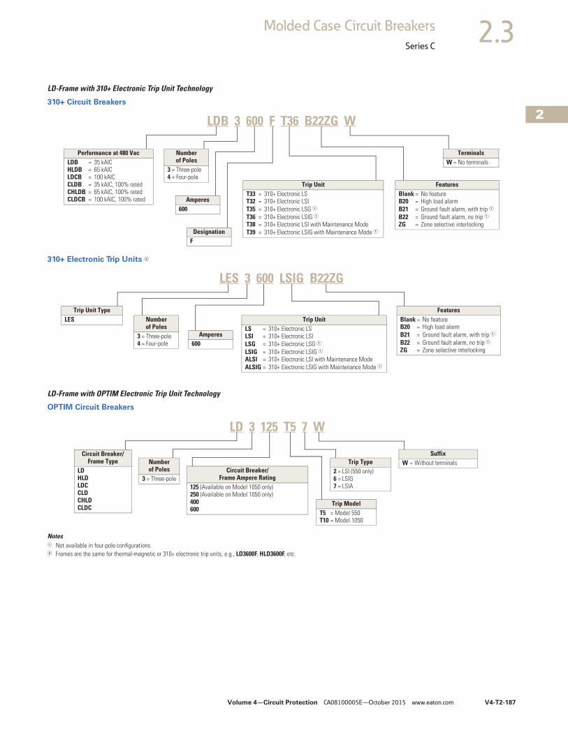
Volume 4—Circuit Protection CA08100005E—October 2015 www.eaton.com V4-T2-187
2
2
2
2
2
2
2
2
2
2
2
2
2
2
2
2
2
2
2
2
2
2
2
2
2
2
2
2
2
2
2.3Molded Case Circuit Breakers
Series C
LD-Frame with 310+ Electronic Trip Unit Technology
310+ Circuit Breakers
310+ Electronic Trip Units 2
LD-Frame with OPTIM Electronic Trip Unit Technology
OPTIM Circuit Breakers
Notes1 Not available in four-pole configurations.2 Frames are the same for thermal-magnetic or 310+ electronic trip units, e.g., LD3600F, HLD3600F, etc.
LDB 3 600 F T36 B22ZG W
Performance at 480 VacLDB = 35 kAICHLDB = 65 kAICLDCB = 100 kAICCLDB = 35 kAIC, 100% ratedCHLDB = 65 kAIC, 100% ratedCLDCB = 100 kAIC, 100% rated
Number of Poles
3 = Three-pole4 = Four-pole
TerminalsW = No terminals
Amperes600
DesignationF
FeaturesBlank = No featureB20 = High load alarmB21 = Ground fault alarm, with trip 1B22 = Ground fault alarm, no trip 1ZG = Zone selective interlocking
Trip UnitT33 = 310+ Electronic LST32 = 310+ Electronic LSIT35 = 310+ Electronic LSG 1T36 = 310+ Electronic LSIG 1T38 = 310+ Electronic LSI with Maintenance ModeT39 = 310+ Electronic LSIG with Maintenance Mode 1
LES 3 600 LSIG B22ZG
Trip Unit TypeLES Number
of Poles3 = Three-pole4 = Four-pole
Amperes600
FeaturesBlank = No featureB20 = High load alarmB21 = Ground fault alarm, with trip 1B22 = Ground fault alarm, no trip 1ZG = Zone selective interlocking
Trip UnitLS = 310+ Electronic LSLSI = 310+ Electronic LSILSG = 310+ Electronic LSG 1LSIG = 310+ Electronic LSIG 1ALSI = 310+ Electronic LSI with Maintenance ModeALSIG = 310+ Electronic LSIG with Maintenance Mode 1
Circuit Breaker/Frame Type
LDHLDLDCCLDCHLDCLDC
Trip Type2 = LSI (550 only)6 = LSIG 7 = LSIA
SuffixW = Without terminals
Circuit Breaker/Frame Ampere Rating
125 (Available on Model 1050 only)250 (Available on Model 1050 only)400600
Number of Poles
3 = Three-pole
Trip ModelT5 = Model 550T10 = Model 1050
LD 3 125 T5 7 W
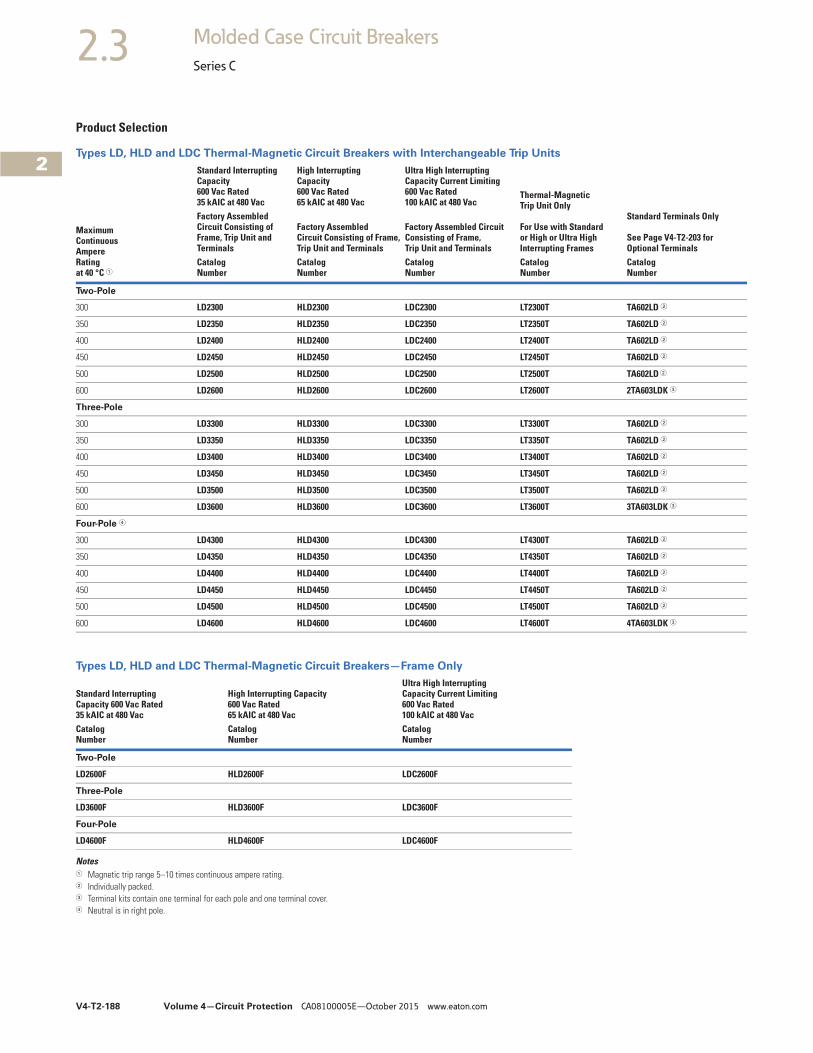
V4-T2-188 Volume 4—Circuit Protection CA08100005E—October 2015 www.eaton.com
2
2
2
2
2
2
2
2
2
2
2
2
2
2
2
2
2
2
2
2
2
2
2
2
2
2
2
2
2
2
2.3 Molded Case Circuit Breakers
Series C
Product Selection
Types LD, HLD and LDC Thermal-Magnetic Circuit Breakers with Interchangeable Trip Units
Types LD, HLD and LDC Thermal-Magnetic Circuit Breakers—Frame Only
Notes1 Magnetic trip range 5–10 times continuous ampere rating.2 Individually packed.3 Terminal kits contain one terminal for each pole and one terminal cover.4 Neutral is in right pole.
MaximumContinuousAmpereRatingat 40 °C 1
Standard InterruptingCapacity600 Vac Rated35 kAIC at 480 Vac
High InterruptingCapacity600 Vac Rated65 kAIC at 480 Vac
Ultra High Interrupting Capacity Current Limiting600 Vac Rated100 kAIC at 480 Vac
Thermal-MagneticTrip Unit Only
For Use with Standardor High or Ultra HighInterrupting Frames
Standard Terminals Only
See Page V4-T2-203 for Optional Terminals
Factory AssembledCircuit Consisting of Frame, Trip Unit and Terminals
Factory AssembledCircuit Consisting of Frame, Trip Unit and Terminals
Factory Assembled Circuit Consisting of Frame, Trip Unit and Terminals
CatalogNumber
CatalogNumber
CatalogNumber
CatalogNumber
CatalogNumber
Two-Pole
300 LD2300 HLD2300 LDC2300 LT2300T TA602LD 2
350 LD2350 HLD2350 LDC2350 LT2350T TA602LD 2
400 LD2400 HLD2400 LDC2400 LT2400T TA602LD 2
450 LD2450 HLD2450 LDC2450 LT2450T TA602LD 2
500 LD2500 HLD2500 LDC2500 LT2500T TA602LD 2
600 LD2600 HLD2600 LDC2600 LT2600T 2TA603LDK 3
Three-Pole
300 LD3300 HLD3300 LDC3300 LT3300T TA602LD 2
350 LD3350 HLD3350 LDC3350 LT3350T TA602LD 2
400 LD3400 HLD3400 LDC3400 LT3400T TA602LD 2
450 LD3450 HLD3450 LDC3450 LT3450T TA602LD 2
500 LD3500 HLD3500 LDC3500 LT3500T TA602LD 2
600 LD3600 HLD3600 LDC3600 LT3600T 3TA603LDK 3
Four-Pole 4
300 LD4300 HLD4300 LDC4300 LT4300T TA602LD 2
350 LD4350 HLD4350 LDC4350 LT4350T TA602LD 2
400 LD4400 HLD4400 LDC4400 LT4400T TA602LD 2
450 LD4450 HLD4450 LDC4450 LT4450T TA602LD 2
500 LD4500 HLD4500 LDC4500 LT4500T TA602LD 2
600 LD4600 HLD4600 LDC4600 LT4600T 4TA603LDK 3
Standard InterruptingCapacity 600 Vac Rated35 kAIC at 480 Vac
High Interrupting Capacity600 Vac Rated65 kAIC at 480 Vac
Ultra High InterruptingCapacity Current Limiting600 Vac Rated100 kAIC at 480 Vac
CatalogNumber
CatalogNumber
CatalogNumber
Two-Pole
LD2600F HLD2600F LDC2600F
Three-Pole
LD3600F HLD3600F LDC3600F
Four-Pole
LD4600F HLD4600F LDC4600F
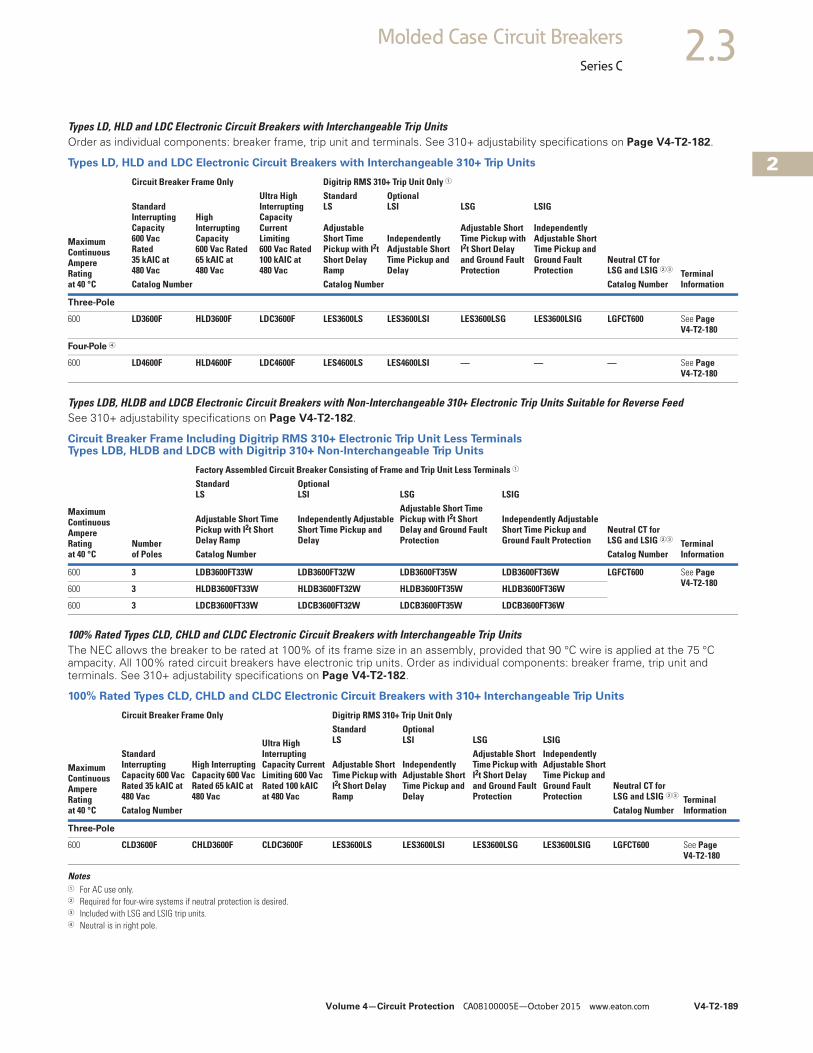
Volume 4—Circuit Protection CA08100005E—October 2015 www.eaton.com V4-T2-189
2
2
2
2
2
2
2
2
2
2
2
2
2
2
2
2
2
2
2
2
2
2
2
2
2
2
2
2
2
2
2.3Molded Case Circuit Breakers
Series C
Types LD, HLD and LDC Electronic Circuit Breakers with Interchangeable Trip UnitsOrder as individual components: breaker frame, trip unit and terminals. See 310+ adjustability specifications on Page V4-T2-182.
Types LD, HLD and LDC Electronic Circuit Breakers with Interchangeable 310+ Trip Units
Types LDB, HLDB and LDCB Electronic Circuit Breakers with Non-Interchangeable 310+ Electronic Trip Units Suitable for Reverse FeedSee 310+ adjustability specifications on Page V4-T2-182.
Circuit Breaker Frame Including Digitrip RMS 310+ Electronic Trip Unit Less TerminalsTypes LDB, HLDB and LDCB with Digitrip 310+ Non-Interchangeable Trip Units
100% Rated Types CLD, CHLD and CLDC Electronic Circuit Breakers with Interchangeable Trip UnitsThe NEC allows the breaker to be rated at 100% of its frame size in an assembly, provided that 90 °C wire is applied at the 75 °C ampacity. All 100% rated circuit breakers have electronic trip units. Order as individual components: breaker frame, trip unit and terminals. See 310+ adjustability specifications on Page V4-T2-182.
100% Rated Types CLD, CHLD and CLDC Electronic Circuit Breakers with 310+ Interchangeable Trip Units
Notes1 For AC use only.2 Required for four-wire systems if neutral protection is desired.3 Included with LSG and LSIG trip units.4 Neutral is in right pole.
MaximumContinuousAmpereRatingat 40 °C
Circuit Breaker Frame Only Digitrip RMS 310+ Trip Unit Only 1
Terminal Information
Standard Interrupting Capacity600 VacRated35 kAIC at480 Vac
High Interrupting Capacity 600 Vac Rated 65 kAIC at 480 Vac
Ultra High Interrupting Capacity Current Limiting 600 Vac Rated 100 kAIC at 480 Vac
StandardLS
OptionalLSI LSG LSIG
Adjustable Short Time Pickup with I2t Short Delay Ramp
Independently Adjustable Short Time Pickup and Delay
Adjustable Short Time Pickup with I2t Short Delay and Ground Fault Protection
Independently Adjustable Short Time Pickup and Ground Fault Protection
Neutral CT forLSG and LSIG 23
Catalog Number Catalog Number Catalog Number
Three-Pole
600 LD3600F HLD3600F LDC3600F LES3600LS LES3600LSI LES3600LSG LES3600LSIG LGFCT600 See PageV4-T2-180
Four-Pole 4
600 LD4600F HLD4600F LDC4600F LES4600LS LES4600LSI — — — See PageV4-T2-180
MaximumContinuousAmpereRatingat 40 °C
Numberof Poles
Factory Assembled Circuit Breaker Consisting of Frame and Trip Unit Less Terminals 1
Terminal Information
StandardLS
OptionalLSI LSG LSIG
Adjustable Short Time Pickup with I2t Short Delay Ramp
Independently Adjustable Short Time Pickup and Delay
Adjustable Short Time Pickup with I2t Short Delay and Ground Fault Protection
Independently Adjustable Short Time Pickup and Ground Fault Protection
Neutral CT forLSG and LSIG 23
Catalog Number Catalog Number
600 3 LDB3600FT33W LDB3600FT32W LDB3600FT35W LDB3600FT36W LGFCT600 See PageV4-T2-180
600 3 HLDB3600FT33W HLDB3600FT32W HLDB3600FT35W HLDB3600FT36W
600 3 LDCB3600FT33W LDCB3600FT32W LDCB3600FT35W LDCB3600FT36W
MaximumContinuousAmpereRatingat 40 °C
Circuit Breaker Frame Only Digitrip RMS 310+ Trip Unit Only
TerminalInformation
Standard Interrupting Capacity 600 Vac Rated 35 kAIC at 480 Vac
High Interrupting Capacity 600 Vac Rated 65 kAIC at 480 Vac
Ultra High Interrupting Capacity Current Limiting 600 Vac Rated 100 kAIC at 480 Vac
StandardLS
OptionalLSI LSG LSIG
Adjustable Short Time Pickup with I2t Short Delay Ramp
Independently Adjustable Short Time Pickup and Delay
Adjustable Short Time Pickup with I2t Short Delay and Ground Fault Protection
Independently Adjustable Short Time Pickup and Ground Fault Protection
Neutral CT forLSG and LSIG 23
Catalog Number Catalog Number
Three-Pole
600 CLD3600F CHLD3600F CLDC3600F LES3600LS LES3600LSI LES3600LSG LES3600LSIG LGFCT600 See PageV4-T2-180
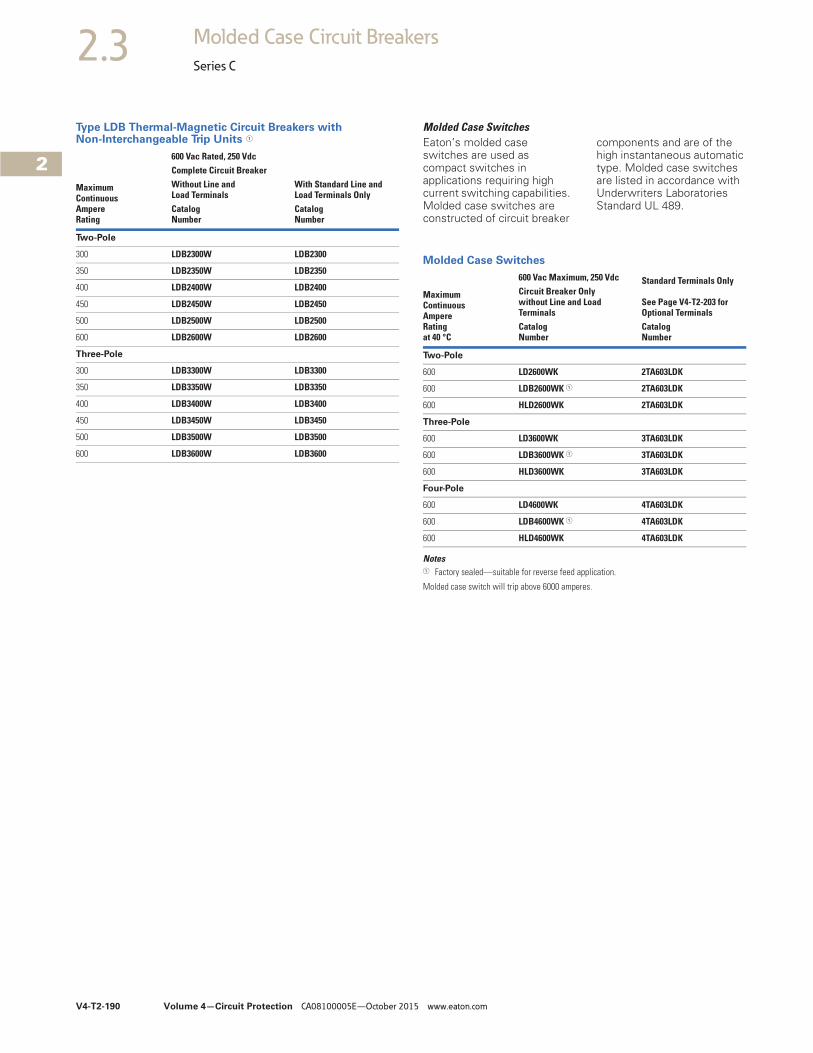
V4-T2-190 Volume 4—Circuit Protection CA08100005E—October 2015 www.eaton.com
2
2
2
2
2
2
2
2
2
2
2
2
2
2
2
2
2
2
2
2
2
2
2
2
2
2
2
2
2
2
2.3 Molded Case Circuit Breakers
Series C
Type LDB Thermal-Magnetic Circuit Breakers with Non-Interchangeable Trip Units 1
MaximumContinuousAmpereRating
600 Vac Rated, 250 VdcComplete Circuit BreakerWithout Line andLoad Terminals
With Standard Line andLoad Terminals Only
CatalogNumber
CatalogNumber
Two-Pole
300 LDB2300W LDB2300
350 LDB2350W LDB2350
400 LDB2400W LDB2400
450 LDB2450W LDB2450
500 LDB2500W LDB2500
600 LDB2600W LDB2600
Three-Pole
300 LDB3300W LDB3300
350 LDB3350W LDB3350
400 LDB3400W LDB3400
450 LDB3450W LDB3450
500 LDB3500W LDB3500
600 LDB3600W LDB3600
Molded Case SwitchesEaton’s molded case switches are used as compact switches in applications requiring high current switching capabilities. Molded case switches are constructed of circuit breaker
components and are of the high instantaneous automatic type. Molded case switches are listed in accordance with Underwriters Laboratories Standard UL 489.
Molded Case Switches
Notes1 Factory sealed—suitable for reverse feed application.
Molded case switch will trip above 6000 amperes.
MaximumContinuousAmpereRatingat 40 °C
600 Vac Maximum, 250 Vdc Standard Terminals Only
See Page V4-T2-203 forOptional Terminals
Circuit Breaker Onlywithout Line and LoadTerminalsCatalogNumber
CatalogNumber
Two-Pole
600 LD2600WK 2TA603LDK
600 LDB2600WK 1 2TA603LDK
600 HLD2600WK 2TA603LDK
Three-Pole
600 LD3600WK 3TA603LDK
600 LDB3600WK 1 3TA603LDK
600 HLD3600WK 3TA603LDK
Four-Pole
600 LD4600WK 4TA603LDK
600 LDB4600WK 1 4TA603LDK
600 HLD4600WK 4TA603LDK
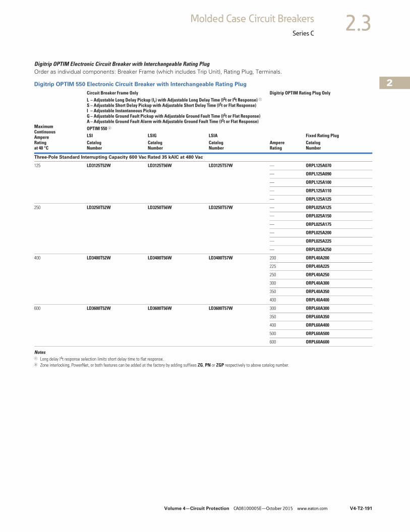
Volume 4—Circuit Protection CA08100005E—October 2015 www.eaton.com V4-T2-191
2
2
2
2
2
2
2
2
2
2
2
2
2
2
2
2
2
2
2
2
2
2
2
2
2
2
2
2
2
2
2.3Molded Case Circuit Breakers
Series C
Digitrip OPTIM Electronic Circuit Breaker with Interchangeable Rating PlugOrder as individual components: Breaker Frame (which includes Trip Unit), Rating Plug, Terminals.
Digitrip OPTIM 550 Electronic Circuit Breaker with Interchangeable Rating Plug
Notes1 Long delay I4t response selection limits short delay time to flat response.2 Zone interlocking, PowerNet, or both features can be added at the factory by adding suffixes ZG, PN or ZGP respectively to above catalog number.
MaximumContinuousAmpereRatingat 40 °C
Circuit Breaker Frame Only Digitrip OPTIM Rating Plug OnlyL – Adjustable Long Delay Pickup (Ir) with Adjustable Long Delay Time (I2t or I4t Response) 1S – Adjustable Short Delay Pickup with Adjustable Short Delay Time (I2t or Flat Response)I – Adjustable Instantaneous Pickup G – Adjustable Ground Fault Pickup with Adjustable Ground Fault Time (I2t or Flat Response)A – Adjustable Ground Fault Alarm with Adjustable Ground Fault Time (I2t or Flat Response)
AmpereRating
Fixed Rating PlugOPTIM 550 2
LSI LSIG LSIACatalogNumber
CatalogNumber
CatalogNumber
CatalogNumber
Three-Pole Standard Interrupting Capacity 600 Vac Rated 35 kAIC at 480 Vac
125 LD3125T52W LD3125T56W LD3125T57W — ORPL125A070
— ORPL125A090
— ORPL125A100
— ORPL125A110
— ORPL125A125
250 LD3250T52W LD3250T56W LD3250T57W — ORPL025A125
— ORPL025A150
— ORPL025A175
— ORPL025A200
— ORPL025A225
— ORPL025A250
400 LD3400T52W LD3400T56W LD3400T57W 200 ORPL40A200
225 ORPL40A225
250 ORPL40A250
300 ORPL40A300
350 ORPL40A350
400 ORPL40A400
600 LD3600T52W LD3600T56W LD3600T57W 300 ORPL60A300
350 ORPL60A350
400 ORPL60A400
500 ORPL60A500
600 ORPL60A600
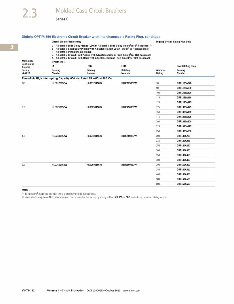
V4-T2-192 Volume 4—Circuit Protection CA08100005E—October 2015 www.eaton.com
2
2
2
2
2
2
2
2
2
2
2
2
2
2
2
2
2
2
2
2
2
2
2
2
2
2
2
2
2
2
2.3 Molded Case Circuit Breakers
Series C
Digitrip OPTIM 550 Electronic Circuit Breaker with Interchangeable Rating Plug, continued
Notes1 Long delay I4t response selection limits short delay time to flat response.2 Zone interlocking, PowerNet, or both features can be added at the factory by adding suffixes ZG, PN or ZGP respectively to above catalog number.
MaximumContinuousAmpereRatingat 40 °C
Circuit Breaker Frame Only Digitrip OPTIM Rating Plug OnlyL – Adjustable Long Delay Pickup (Ir) with Adjustable Long Delay Time (I2t or I4t Response) 1S – Adjustable Short Delay Pickup with Adjustable Short Delay Time (I2t or Flat Response)I – Adjustable Instantaneous Pickup G – Adjustable Ground Fault Pickup with Adjustable Ground Fault Time (I2t or Flat Response)A – Adjustable Ground Fault Alarm with Adjustable Ground Fault Time (I2t or Flat Response)
AmpereRating
Fixed Rating PlugOPTIM 550 2
LSI LSIG LSIACatalogNumber
CatalogNumber
CatalogNumber
CatalogNumber
Three-Pole High Interrupting Capacity 600 Vac Rated 65 kAIC at 480 Vac
125 HLD3125T52W HLD3125T56W HLD3125T57W 70 ORPL125A070
90 ORPL125A090
100 ORPL125A100
110 ORPL125A110
125 ORPL125A125
250 HLD3250T52W HLD3250T56W HLD3250T57W 125 ORPL025A125
150 ORPL025A150
175 ORPL025A175
200 ORPL025A200
225 ORPL025A225
250 ORPL025A250
400 HLD3400T52W HLD3400T56W HLD3400T57W 200 ORPL40A200
225 ORPL40A225
250 ORPL40A250
300 ORPL40A300
350 ORPL40A350
400 ORPL40A400
600 HLD3600T52W HLD3600T56W HLD3600T57W 300 ORPL60A300
350 ORPL60A350
400 ORPL60A400
500 ORPL60A500
600 ORPL60A600
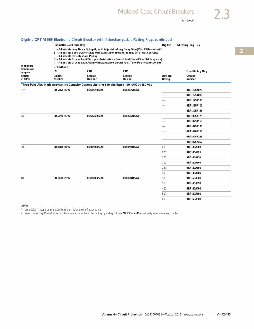
Volume 4—Circuit Protection CA08100005E—October 2015 www.eaton.com V4-T2-193
2
2
2
2
2
2
2
2
2
2
2
2
2
2
2
2
2
2
2
2
2
2
2
2
2
2
2
2
2
2
2.3Molded Case Circuit Breakers
Series C
Digitrip OPTIM 550 Electronic Circuit Breaker with Interchangeable Rating Plug, continued
Notes1 Long delay I4t response selection limits short delay time to flat response.2 Zone interlocking, PowerNet, or both features can be added at the factory by adding suffixes ZG, PN or ZGP respectively to above catalog number.
MaximumContinuousAmpereRatingat 40 °C
Circuit Breaker Frame Only Digitrip OPTIM Rating Plug OnlyL – Adjustable Long Delay Pickup (Ir) with Adjustable Long Delay Time (I2t or I4t Response) 1S – Adjustable Short Delay Pickup with Adjustable Short Delay Time (I2t or Flat Response)I – Adjustable Instantaneous Pickup G – Adjustable Ground Fault Pickup with Adjustable Ground Fault Time (I2t or Flat Response)A – Adjustable Ground Fault Alarm with Adjustable Ground Fault Time (I2t or Flat Response)
AmpereRating
Fixed Rating PlugOPTIM 550 2
LSI LSIG LSIACatalogNumber
CatalogNumber
CatalogNumber
CatalogNumber
Three-Pole Ultra High Interrupting Capacity Current Limiting 600 Vac Rated 100 kAIC at 480 Vac
125 LDC3125T52W LDC3125T56W LDC3125T57W — ORPL125A070
— ORPL125A090
— ORPL125A100
— ORPL125A110
— ORPL125A125
250 LDC3250T52W LDC3250T56W LDC3250T57W — ORPL025A125
— ORPL025A150
— ORPL025A175
— ORPL025A200
— ORPL025A225
— ORPL025A250
400 LDC3400T52W LDC3400T56W LDC3400T57W 200 ORPL40A200
225 ORPL40A225
250 ORPL40A250
300 ORPL40A300
350 ORPL40A350
400 ORPL40A400
600 LDC3600T52W LDC3600T56W LDC3600T57W 300 ORPL60A300
350 ORPL60A350
400 ORPL60A400
500 ORPL60A500
600 ORPL60A600
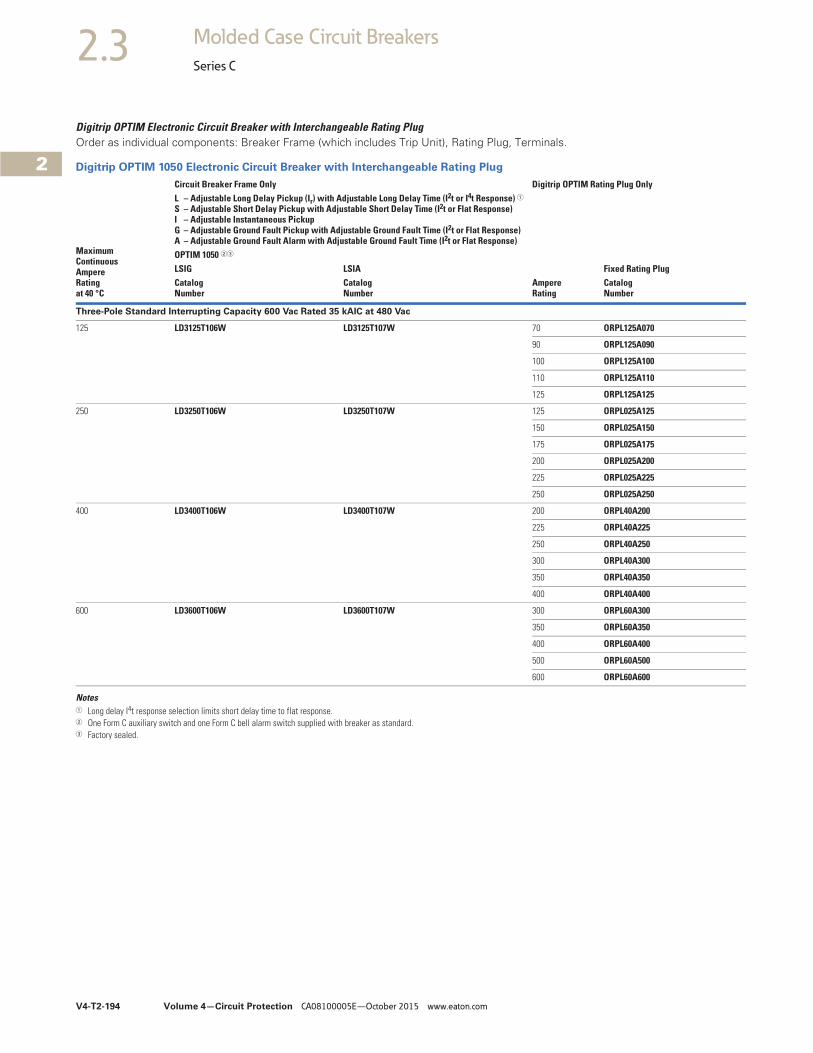
V4-T2-194 Volume 4—Circuit Protection CA08100005E—October 2015 www.eaton.com
2
2
2
2
2
2
2
2
2
2
2
2
2
2
2
2
2
2
2
2
2
2
2
2
2
2
2
2
2
2
2.3 Molded Case Circuit Breakers
Series C
Digitrip OPTIM Electronic Circuit Breaker with Interchangeable Rating PlugOrder as individual components: Breaker Frame (which includes Trip Unit), Rating Plug, Terminals.
Digitrip OPTIM 1050 Electronic Circuit Breaker with Interchangeable Rating Plug
Notes1 Long delay I4t response selection limits short delay time to flat response.2 One Form C auxiliary switch and one Form C bell alarm switch supplied with breaker as standard.3 Factory sealed.
MaximumContinuousAmpereRatingat 40 °C
Circuit Breaker Frame Only Digitrip OPTIM Rating Plug OnlyL – Adjustable Long Delay Pickup (Ir) with Adjustable Long Delay Time (I2t or I4t Response) 1S – Adjustable Short Delay Pickup with Adjustable Short Delay Time (I2t or Flat Response)I – Adjustable Instantaneous Pickup G – Adjustable Ground Fault Pickup with Adjustable Ground Fault Time (I2t or Flat Response)A – Adjustable Ground Fault Alarm with Adjustable Ground Fault Time (I2t or Flat Response)
Ampere Rating
Fixed Rating PlugOPTIM 1050 23
LSIG LSIACatalogNumber
CatalogNumber
CatalogNumber
Three-Pole Standard Interrupting Capacity 600 Vac Rated 35 kAIC at 480 Vac
125 LD3125T106W LD3125T107W 70 ORPL125A070
90 ORPL125A090
100 ORPL125A100
110 ORPL125A110
125 ORPL125A125
250 LD3250T106W LD3250T107W 125 ORPL025A125
150 ORPL025A150
175 ORPL025A175
200 ORPL025A200
225 ORPL025A225
250 ORPL025A250
400 LD3400T106W LD3400T107W 200 ORPL40A200
225 ORPL40A225
250 ORPL40A250
300 ORPL40A300
350 ORPL40A350
400 ORPL40A400
600 LD3600T106W LD3600T107W 300 ORPL60A300
350 ORPL60A350
400 ORPL60A400
500 ORPL60A500
600 ORPL60A600
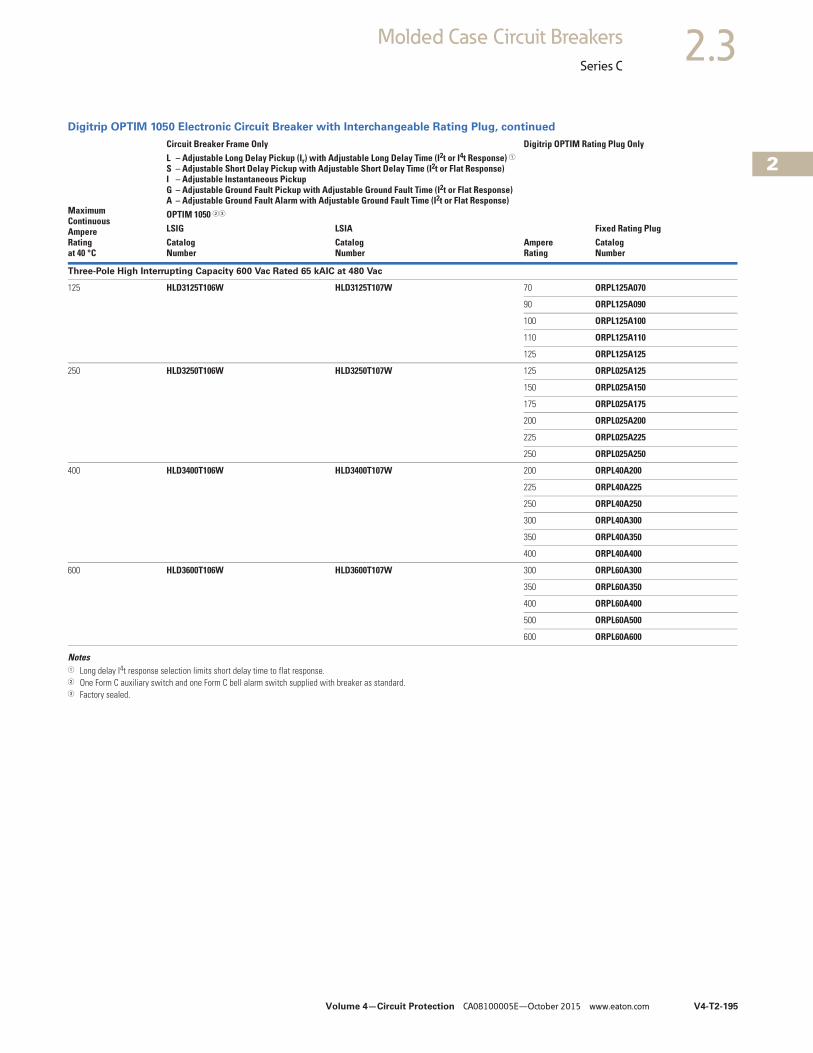
Volume 4—Circuit Protection CA08100005E—October 2015 www.eaton.com V4-T2-195
2
2
2
2
2
2
2
2
2
2
2
2
2
2
2
2
2
2
2
2
2
2
2
2
2
2
2
2
2
2
2.3Molded Case Circuit Breakers
Series C
Digitrip OPTIM 1050 Electronic Circuit Breaker with Interchangeable Rating Plug, continued
Notes1 Long delay I4t response selection limits short delay time to flat response.2 One Form C auxiliary switch and one Form C bell alarm switch supplied with breaker as standard.3 Factory sealed.
MaximumContinuousAmpereRatingat 40 °C
Circuit Breaker Frame Only Digitrip OPTIM Rating Plug OnlyL – Adjustable Long Delay Pickup (Ir) with Adjustable Long Delay Time (I2t or I4t Response) 1S – Adjustable Short Delay Pickup with Adjustable Short Delay Time (I2t or Flat Response)I – Adjustable Instantaneous Pickup G – Adjustable Ground Fault Pickup with Adjustable Ground Fault Time (I2t or Flat Response)A – Adjustable Ground Fault Alarm with Adjustable Ground Fault Time (I2t or Flat Response)
Ampere Rating
Fixed Rating PlugOPTIM 1050 23
LSIG LSIACatalogNumber
CatalogNumber
CatalogNumber
Three-Pole High Interrupting Capacity 600 Vac Rated 65 kAIC at 480 Vac
125 HLD3125T106W HLD3125T107W 70 ORPL125A070
90 ORPL125A090
100 ORPL125A100
110 ORPL125A110
125 ORPL125A125
250 HLD3250T106W HLD3250T107W 125 ORPL025A125
150 ORPL025A150
175 ORPL025A175
200 ORPL025A200
225 ORPL025A225
250 ORPL025A250
400 HLD3400T106W HLD3400T107W 200 ORPL40A200
225 ORPL40A225
250 ORPL40A250
300 ORPL40A300
350 ORPL40A350
400 ORPL40A400
600 HLD3600T106W HLD3600T107W 300 ORPL60A300
350 ORPL60A350
400 ORPL60A400
500 ORPL60A500
600 ORPL60A600
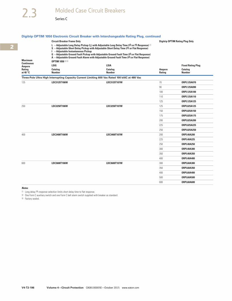
V4-T2-196 Volume 4—Circuit Protection CA08100005E—October 2015 www.eaton.com
2
2
2
2
2
2
2
2
2
2
2
2
2
2
2
2
2
2
2
2
2
2
2
2
2
2
2
2
2
2
2.3 Molded Case Circuit Breakers
Series C
Digitrip OPTIM 1050 Electronic Circuit Breaker with Interchangeable Rating Plug, continued
Notes1 Long delay I4t response selection limits short delay time to flat response.2 One Form C auxiliary switch and one Form C bell alarm switch supplied with breaker as standard.3 Factory sealed.
MaximumContinuousAmpereRatingat 40 °C
Circuit Breaker Frame Only Digitrip OPTIM Rating Plug OnlyL – Adjustable Long Delay Pickup (Ir) with Adjustable Long Delay Time (I2t or I4t Response) 1S – Adjustable Short Delay Pickup with Adjustable Short Delay Time (I2t or Flat Response)I – Adjustable Instantaneous Pickup G – Adjustable Ground Fault Pickup with Adjustable Ground Fault Time (I2t or Flat Response)A – Adjustable Ground Fault Alarm with Adjustable Ground Fault Time (I2t or Flat Response)
AmpereRating
Fixed Rating PlugOPTIM 1050 23
LSIG LSIACatalogNumber
CatalogNumber
CatalogNumber
Three-Pole Ultra High Interrupting Capacity Current Limiting 600 Vac Rated 100 kAIC at 480 Vac
125 LDC3125T106W LDC3125T107W 70 ORPL125A070
90 ORPL125A090
100 ORPL125A100
110 ORPL125A110
125 ORPL125A125
250 LDC3250T106W LDC3250T107W 125 ORPL025A125
150 ORPL025A150
175 ORPL025A175
200 ORPL025A200
225 ORPL025A225
250 ORPL025A250
400 LDC3400T106W LDC3400T107W 200 ORPL40A200
225 ORPL40A225
250 ORPL40A250
300 ORPL40A300
350 ORPL40A350
400 ORPL40A400
600 LDC3600T106W LDC3600T107W 300 ORPL60A300
350 ORPL60A350
400 ORPL60A400
500 ORPL60A500
600 ORPL60A600
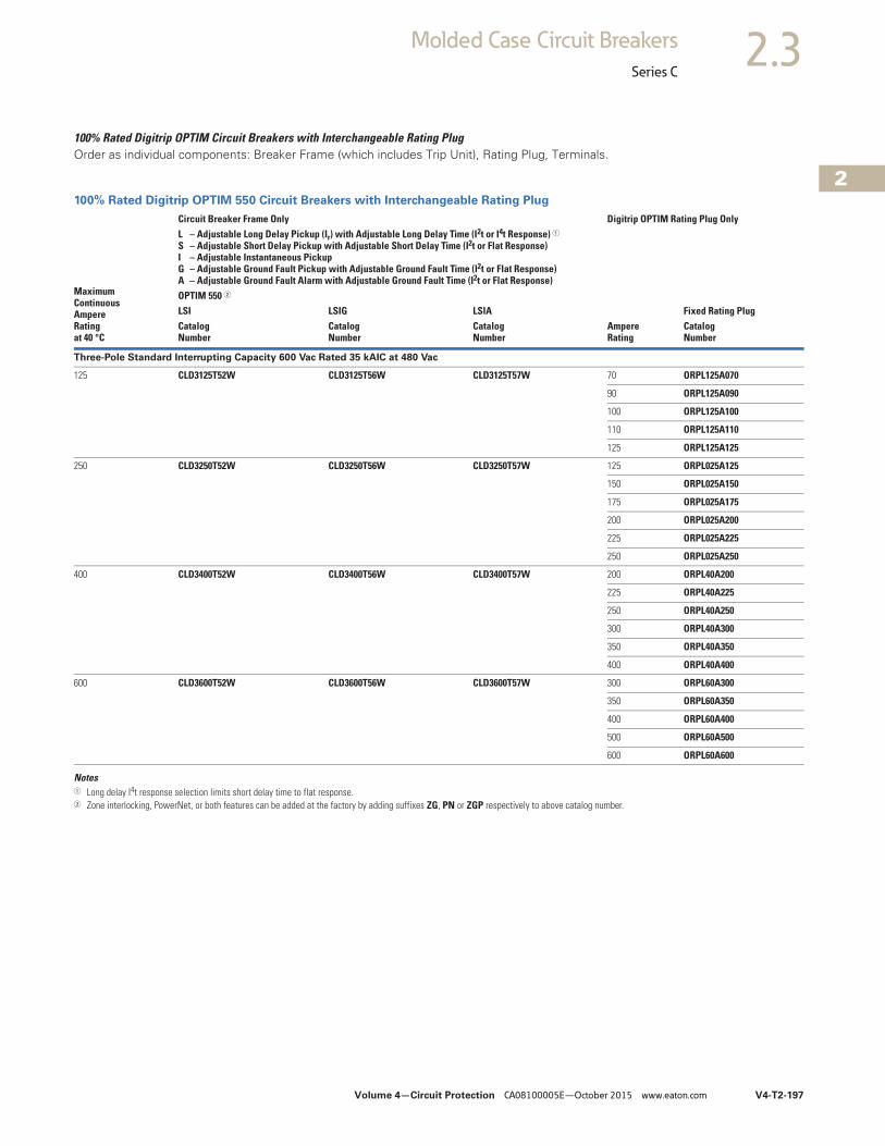
Volume 4—Circuit Protection CA08100005E—October 2015 www.eaton.com V4-T2-197
2
2
2
2
2
2
2
2
2
2
2
2
2
2
2
2
2
2
2
2
2
2
2
2
2
2
2
2
2
2
2.3Molded Case Circuit Breakers
Series C
100% Rated Digitrip OPTIM Circuit Breakers with Interchangeable Rating PlugOrder as individual components: Breaker Frame (which includes Trip Unit), Rating Plug, Terminals.
100% Rated Digitrip OPTIM 550 Circuit Breakers with Interchangeable Rating Plug
Notes1 Long delay I4t response selection limits short delay time to flat response.2 Zone interlocking, PowerNet, or both features can be added at the factory by adding suffixes ZG, PN or ZGP respectively to above catalog number.
MaximumContinuousAmpereRatingat 40 °C
Circuit Breaker Frame Only Digitrip OPTIM Rating Plug OnlyL – Adjustable Long Delay Pickup (Ir) with Adjustable Long Delay Time (I2t or I4t Response) 1S – Adjustable Short Delay Pickup with Adjustable Short Delay Time (I2t or Flat Response)I – Adjustable Instantaneous Pickup G – Adjustable Ground Fault Pickup with Adjustable Ground Fault Time (I2t or Flat Response)A – Adjustable Ground Fault Alarm with Adjustable Ground Fault Time (I2t or Flat Response)
AmpereRating
Fixed Rating PlugOPTIM 550 2
LSI LSIG LSIACatalogNumber
CatalogNumber
CatalogNumber
CatalogNumber
Three-Pole Standard Interrupting Capacity 600 Vac Rated 35 kAIC at 480 Vac
125 CLD3125T52W CLD3125T56W CLD3125T57W 70 ORPL125A070
90 ORPL125A090
100 ORPL125A100
110 ORPL125A110
125 ORPL125A125
250 CLD3250T52W CLD3250T56W CLD3250T57W 125 ORPL025A125
150 ORPL025A150
175 ORPL025A175
200 ORPL025A200
225 ORPL025A225
250 ORPL025A250
400 CLD3400T52W CLD3400T56W CLD3400T57W 200 ORPL40A200
225 ORPL40A225
250 ORPL40A250
300 ORPL40A300
350 ORPL40A350
400 ORPL40A400
600 CLD3600T52W CLD3600T56W CLD3600T57W 300 ORPL60A300
350 ORPL60A350
400 ORPL60A400
500 ORPL60A500
600 ORPL60A600
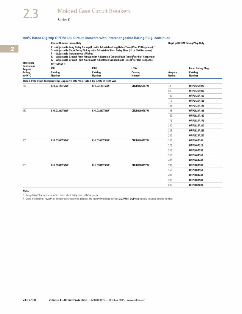
V4-T2-198 Volume 4—Circuit Protection CA08100005E—October 2015 www.eaton.com
2
2
2
2
2
2
2
2
2
2
2
2
2
2
2
2
2
2
2
2
2
2
2
2
2
2
2
2
2
2
2.3 Molded Case Circuit Breakers
Series C
100% Rated Digitrip OPTIM 550 Circuit Breakers with Interchangeable Rating Plug, continued
Notes1 Long delay I4t response selection limits short delay time to flat response.2 Zone interlocking, PowerNet, or both features can be added at the factory by adding suffixes ZG, PN or ZGP respectively to above catalog number.
MaximumContinuousAmpereRatingat 40 °C
Circuit Breaker Frame Only Digitrip OPTIM Rating Plug OnlyL – Adjustable Long Delay Pickup (Ir) with Adjustable Long Delay Time (I2t or I4t Response) 1S – Adjustable Short Delay Pickup with Adjustable Short Delay Time (I2t or Flat Response)I – Adjustable Instantaneous Pickup G – Adjustable Ground Fault Pickup with Adjustable Ground Fault Time (I2t or Flat Response)A – Adjustable Ground Fault Alarm with Adjustable Ground Fault Time (I2t or Flat Response)
AmpereRating
Fixed Rating PlugOPTIM 550 2
LSI LSIG LSIACatalogNumber
CatalogNumber
CatalogNumber
CatalogNumber
Three-Pole High Interrupting Capacity 600 Vac Rated 65 kAIC at 480 Vac
125 CHLD3125T52W CHLD3125T56W CHLD3125T57W 70 ORPL125A070
90 ORPL125A090
100 ORPL125A100
110 ORPL125A125
125 ORPL125A125
250 CHLD3250T52W CHLD3250T56W CHLD3250T57W 125 ORPL025A125
150 ORPL025A150
175 ORPL025A175
200 ORPL025A200
225 ORPL025A225
250 ORPL025A250
400 CHLD3400T52W CHLD3400T56W CHLD3400T57W 200 ORPL40A200
225 ORPL40A225
250 ORPL40A250
350 ORPL40A350
400 ORPL40A400
600 CHLD3600T52W CHLD3600T56W CHLD3600T57W 300 ORPL60A300
350 ORPL60A350
400 ORPL60A400
500 ORPL60A500
600 ORPL60A600
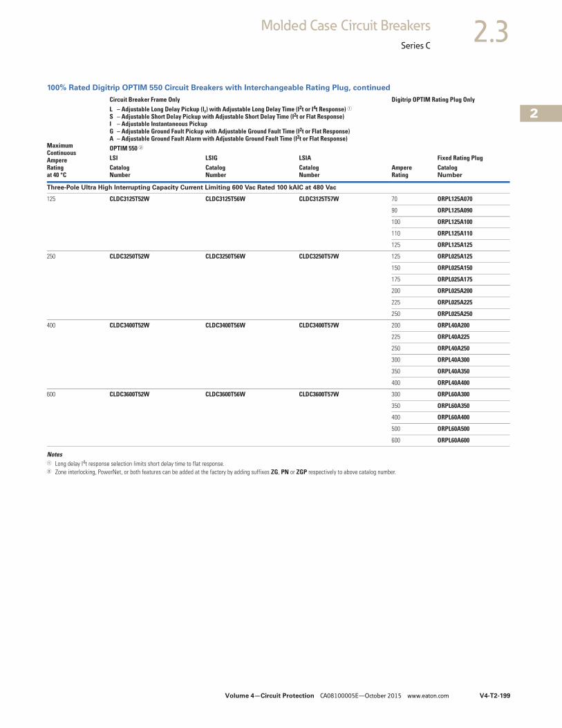
Volume 4—Circuit Protection CA08100005E—October 2015 www.eaton.com V4-T2-199
2
2
2
2
2
2
2
2
2
2
2
2
2
2
2
2
2
2
2
2
2
2
2
2
2
2
2
2
2
2
2.3Molded Case Circuit Breakers
Series C
100% Rated Digitrip OPTIM 550 Circuit Breakers with Interchangeable Rating Plug, continued
Notes1 Long delay I4t response selection limits short delay time to flat response.2 Zone interlocking, PowerNet, or both features can be added at the factory by adding suffixes ZG, PN or ZGP respectively to above catalog number.
MaximumContinuousAmpereRatingat 40 °C
Circuit Breaker Frame Only Digitrip OPTIM Rating Plug OnlyL – Adjustable Long Delay Pickup (Ir) with Adjustable Long Delay Time (I2t or I4t Response) 1S – Adjustable Short Delay Pickup with Adjustable Short Delay Time (I2t or Flat Response)I – Adjustable Instantaneous Pickup G – Adjustable Ground Fault Pickup with Adjustable Ground Fault Time (I2t or Flat Response)A – Adjustable Ground Fault Alarm with Adjustable Ground Fault Time (I2t or Flat Response)
AmpereRating
Fixed Rating PlugOPTIM 550 2
LSI LSIG LSIACatalogNumber
CatalogNumber
CatalogNumber
CatalogNumber
Three-Pole Ultra High Interrupting Capacity Current Limiting 600 Vac Rated 100 kAIC at 480 Vac
125 CLDC3125T52W CLDC3125T56W CLDC3125T57W 70 ORPL125A070
90 ORPL125A090
100 ORPL125A100
110 ORPL125A110
125 ORPL125A125
250 CLDC3250T52W CLDC3250T56W CLDC3250T57W 125 ORPL025A125
150 ORPL025A150
175 ORPL025A175
200 ORPL025A200
225 ORPL025A225
250 ORPL025A250
400 CLDC3400T52W CLDC3400T56W CLDC3400T57W 200 ORPL40A200
225 ORPL40A225
250 ORPL40A250
300 ORPL40A300
350 ORPL40A350
400 ORPL40A400
600 CLDC3600T52W CLDC3600T56W CLDC3600T57W 300 ORPL60A300
350 ORPL60A350
400 ORPL60A400
500 ORPL60A500
600 ORPL60A600
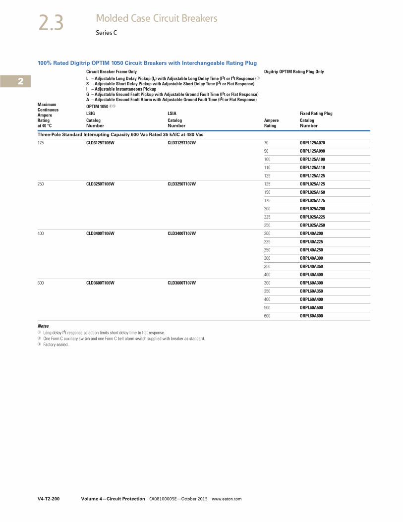
V4-T2-200 Volume 4—Circuit Protection CA08100005E—October 2015 www.eaton.com
2
2
2
2
2
2
2
2
2
2
2
2
2
2
2
2
2
2
2
2
2
2
2
2
2
2
2
2
2
2
2.3 Molded Case Circuit Breakers
Series C
100% Rated Digitrip OPTIM 1050 Circuit Breakers with Interchangeable Rating Plug
Notes1 Long delay I4t response selection limits short delay time to flat response.2 One Form C auxiliary switch and one Form C bell alarm switch supplied with breaker as standard.3 Factory sealed.
MaximumContinuousAmpereRatingat 40 °C
Circuit Breaker Frame Only Digitrip OPTIM Rating Plug OnlyL – Adjustable Long Delay Pickup (Ir) with Adjustable Long Delay Time (I2t or I4t Response) 1S – Adjustable Short Delay Pickup with Adjustable Short Delay Time (I2t or Flat Response)I – Adjustable Instantaneous Pickup G – Adjustable Ground Fault Pickup with Adjustable Ground Fault Time (I2t or Flat Response)A – Adjustable Ground Fault Alarm with Adjustable Ground Fault Time (I2t or Flat Response)
AmpereRating
Fixed Rating PlugOPTIM 1050 23
LSIG LSIACatalogNumber
CatalogNumber
CatalogNumber
Three-Pole Standard Interrupting Capacity 600 Vac Rated 35 kAIC at 480 Vac
125 CLD3125T106W CLD3125T107W 70 ORPL125A070
90 ORPL125A090
100 ORPL125A100
110 ORPL125A110
125 ORPL125A125
250 CLD3250T106W CLD3250T107W 125 ORPL025A125
150 ORPL025A150
175 ORPL025A175
200 ORPL025A200
225 ORPL025A225
250 ORPL025A250
400 CLD3400T106W CLD3400T107W 200 ORPL40A200
225 ORPL40A225
250 ORPL40A250
300 ORPL40A300
350 ORPL40A350
400 ORPL40A400
600 CLD3600T106W CLD3600T107W 300 ORPL60A300
350 ORPL60A350
400 ORPL60A400
500 ORPL60A500
600 ORPL60A600
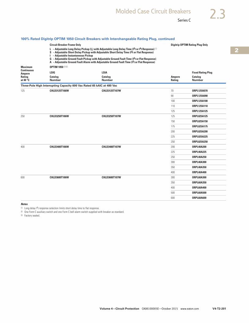
Volume 4—Circuit Protection CA08100005E—October 2015 www.eaton.com V4-T2-201
2
2
2
2
2
2
2
2
2
2
2
2
2
2
2
2
2
2
2
2
2
2
2
2
2
2
2
2
2
2
2.3Molded Case Circuit Breakers
Series C
100% Rated Digitrip OPTIM 1050 Circuit Breakers with Interchangeable Rating Plug, continued
Notes1 Long delay I4t response selection limits short delay time to flat response.2 One Form C auxiliary switch and one Form C bell alarm switch supplied with breaker as standard.3 Factory sealed.
MaximumContinuousAmpereRatingat 40 °C
Circuit Breaker Frame Only Digitrip OPTIM Rating Plug OnlyL – Adjustable Long Delay Pickup (Ir) with Adjustable Long Delay Time (I2t or I4t Response) 1S – Adjustable Short Delay Pickup with Adjustable Short Delay Time (I2t or Flat Response)I – Adjustable Instantaneous Pickup G – Adjustable Ground Fault Pickup with Adjustable Ground Fault Time (I2t or Flat Response)A – Adjustable Ground Fault Alarm with Adjustable Ground Fault Time (I2t or Flat Response)
AmpereRating
Fixed Rating Plug
OPTIM 1050 23
LSIG LSIACatalogNumber
CatalogNumber
CatalogNumber
Three-Pole High Interrupting Capacity 600 Vac Rated 65 kAIC at 480 Vac
125 CHLD3125T106W CHLD3125T107W 70 ORPL125A070
90 ORPL125A090
100 ORPL125A100
110 ORPL125A110
125 ORPL125A125
250 CHLD3250T106W CHLD3250T107W 125 ORPL025A125
150 ORPL025A150
175 ORPL025A175
200 ORPL025A200
225 ORPL025A225
250 ORPL025A250
400 CHLD3400T106W CHLD3400T107W 200 ORPL40A200
225 ORPL40A225
250 ORPL40A250
300 ORPL40A300
350 ORPL40A350
400 ORPL40A400
600 CHLD3600T106W CHLD3600T107W 300 ORPL60A300
350 ORPL60A350
400 ORPL60A400
500 ORPL60A500
600 ORPL60A600
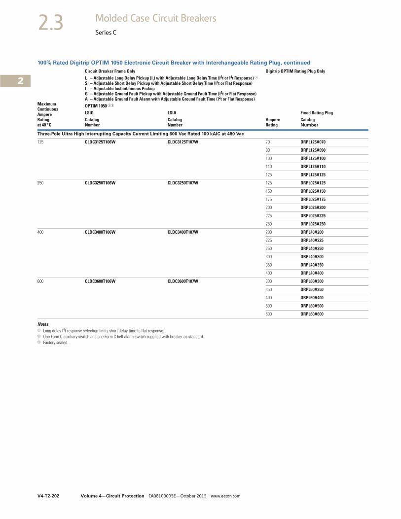
V4-T2-202 Volume 4—Circuit Protection CA08100005E—October 2015 www.eaton.com
2
2
2
2
2
2
2
2
2
2
2
2
2
2
2
2
2
2
2
2
2
2
2
2
2
2
2
2
2
2
2.3 Molded Case Circuit Breakers
Series C
100% Rated Digitrip OPTIM 1050 Electronic Circuit Breaker with Interchangeable Rating Plug, continued
Notes1 Long delay I4t response selection limits short delay time to flat response.2 One Form C auxiliary switch and one Form C bell alarm switch supplied with breaker as standard.3 Factory sealed.
MaximumContinuousAmpereRatingat 40 °C
Circuit Breaker Frame Only Digitrip OPTIM Rating Plug OnlyL – Adjustable Long Delay Pickup (Ir) with Adjustable Long Delay Time (I2t or I4t Response) 1S – Adjustable Short Delay Pickup with Adjustable Short Delay Time (I2t or Flat Response)I – Adjustable Instantaneous Pickup G – Adjustable Ground Fault Pickup with Adjustable Ground Fault Time (I2t or Flat Response)A – Adjustable Ground Fault Alarm with Adjustable Ground Fault Time (I2t or Flat Response)
AmpereRating
Fixed Rating PlugOPTIM 1050 23
LSIG LSIACatalogNumber
CatalogNumber
CatalogNumber
Three-Pole Ultra High Interrupting Capacity Current Limiting 600 Vac Rated 100 kAIC at 480 Vac
125 CLDC3125T106W CLDC3125T107W 70 ORPL125A070
90 ORPL125A090
100 ORPL125A100
110 ORPL125A110
125 ORPL125A125
250 CLDC3250T106W CLDC3250T107W 125 ORPL025A125
150 ORPL025A150
175 ORPL025A175
200 ORPL025A200
225 ORPL025A225
250 ORPL025A250
400 CLDC3400T106W CLDC3400T107W 200 ORPL40A200
225 ORPL40A225
250 ORPL40A250
300 ORPL40A300
350 ORPL40A350
400 ORPL40A400
600 CLDC3600T106W CLDC3600T107W 300 ORPL60A300
350 ORPL60A350
400 ORPL60A400
500 ORPL60A500
600 ORPL60A600
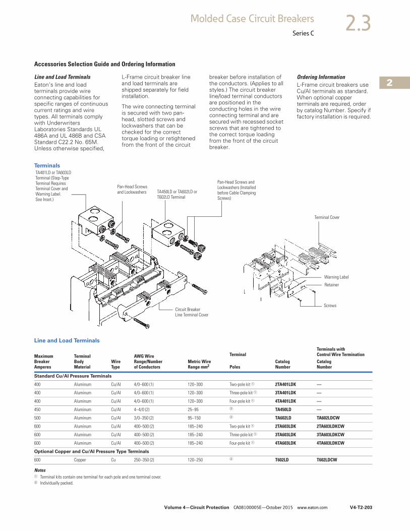
Volume 4—Circuit Protection CA08100005E—October 2015 www.eaton.com V4-T2-203
2
2
2
2
2
2
2
2
2
2
2
2
2
2
2
2
2
2
2
2
2
2
2
2
2
2
2
2
2
2
2.3Molded Case Circuit Breakers
Series C
Accessories Selection Guide and Ordering Information
Line and Load TerminalsEaton’s line and load terminals provide wire connecting capabilities for specific ranges of continuous current ratings and wire types. All terminals comply with Underwriters Laboratories Standards UL 486A and UL 486B and CSA Standard C22.2 No. 65M. Unless otherwise specified,
L-Frame circuit breaker line and load terminals are shipped separately for field installation.
The wire connecting terminal is secured with two pan-head, slotted screws and lockwashers that can be checked for the correct torque loading or retightened from the front of the circuit
breaker before installation of the conductors. (Applies to all styles.) The circuit breaker line/load terminal conductors are positioned in the conducting holes in the wire connecting terminal and are secured with recessed socket screws that are tightened to the correct torque loading from the front of the circuit breaker.
Ordering InformationL-Frame circuit breakers use Cu/AI terminals as standard. When optional copper terminals are required, order by catalog Number. Specify if factory installation is required.
Terminals
Line and Load Terminals
Notes1 Terminal kits contain one terminal for each pole and one terminal cover.2 Individually packed.
MaximumBreakerAmperes
TerminalBodyMaterial
WireType
AWG WireRange/Numberof Conductors
Metric WireRange mm2
TerminalTerminals withControl Wire Termination
PolesCatalogNumber
CatalogNumber
Standard Cu/AI Pressure Terminals
400 Aluminum Cu/AI 4/0–600 (1) 120–300 Two-pole kit 1 2TA401LDK —
400 Aluminum Cu/AI 4/0–600 (1) 120–300 Three-pole kit 1 3TA401LDK —
400 Aluminum Cu/AI 4/0–600 (1) 120–300 Four-pole kit 1 4TA401LDK —
450 Aluminum Cu/AI 4–4/0 (2) 25–95 2 TA450LD —
500 Aluminum Cu/AI 3/0–350 (2) 95–150 2 TA602LD TA602LDCW
600 Aluminum Cu/AI 400–500 (2) 185–240 Two-pole kit 1 2TA603LDK 2TA603LDKCW
600 Aluminum Cu/AI 400–500 (2) 185–240 Three-pole kit 1 3TA603LDK 3TA603LDKCW
600 Aluminum Cu/AI 400–500 (2) 185–240 Four-pole kit 1 4TA603LDK 4TA603LDKCW
Optional Copper and Cu/AI Pressure Type Terminals
600 Copper Cu 250–350 (2) 120–250 2 T602LD T602LDCW
TA450LD or TA602LD or T602LD Terminal
Pan-Head Screws and Lockwashers (Installed before Cable Clamping Screws)
Terminal Cover
Screws
Retainer
TA401LD or TA603LD Terminal (Step-Type Terminal Requires Terminal Cover and Warning Label. See Inset.)
Pan-Head Screws and Lockwashers
Warning Label
Circuit Breaker Line Terminal Cover
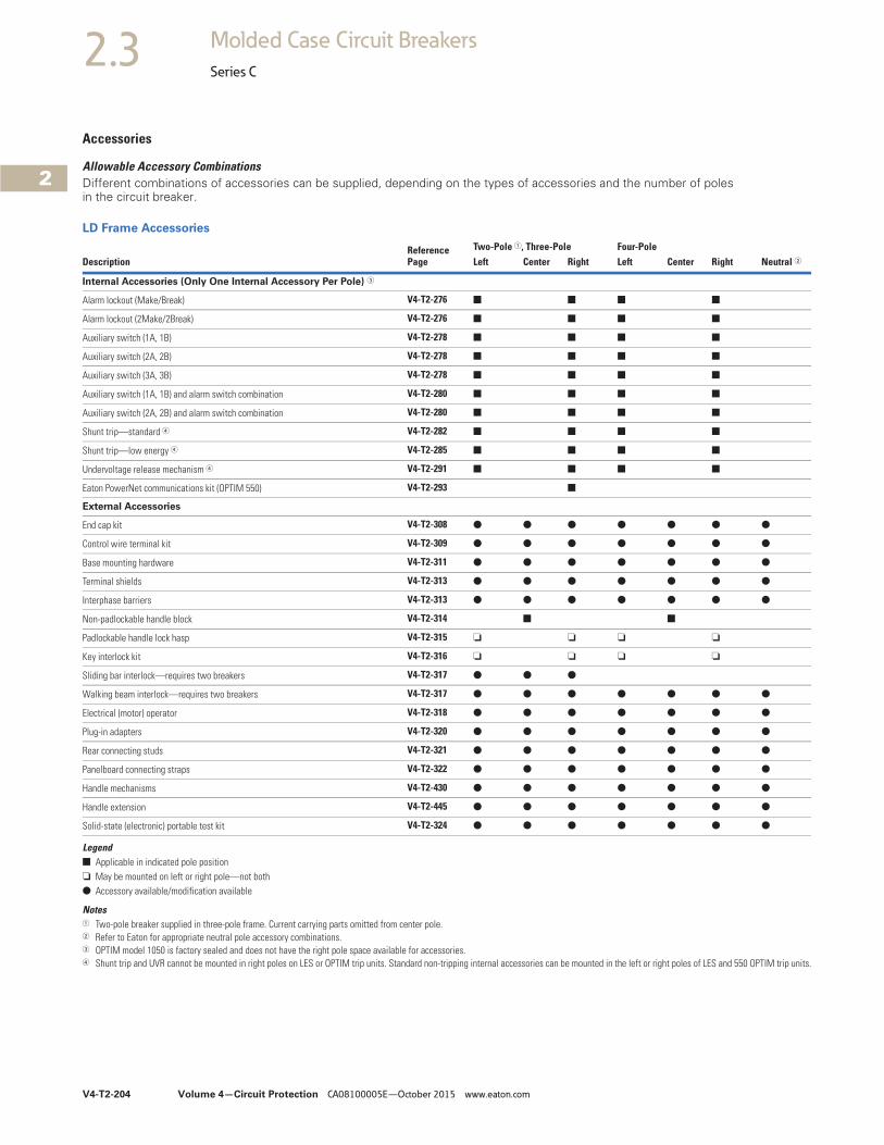
V4-T2-204 Volume 4—Circuit Protection CA08100005E—October 2015 www.eaton.com
2
2
2
2
2
2
2
2
2
2
2
2
2
2
2
2
2
2
2
2
2
2
2
2
2
2
2
2
2
2
2.3 Molded Case Circuit Breakers
Series C
Accessories
Allowable Accessory CombinationsDifferent combinations of accessories can be supplied, depending on the types of accessories and the number of poles in the circuit breaker.
LD Frame Accessories
Legend■ Applicable in indicated pole position❏ May be mounted on left or right pole—not both● Accessory available/modification available
Notes1 Two-pole breaker supplied in three-pole frame. Current carrying parts omitted from center pole.2 Refer to Eaton for appropriate neutral pole accessory combinations.3 OPTIM model 1050 is factory sealed and does not have the right pole space available for accessories.4 Shunt trip and UVR cannot be mounted in right poles on LES or OPTIM trip units. Standard non-tripping internal accessories can be mounted in the left or right poles of LES and 550 OPTIM trip units.
DescriptionReference Page
Two-Pole 1, Three-Pole Four-PoleLeft Center Right Left Center Right Neutral 2
Internal Accessories (Only One Internal Accessory Per Pole) 3
Alarm lockout (Make/Break) V4-T2-276 ■ ■ ■ ■
Alarm lockout (2Make/2Break) V4-T2-276 ■ ■ ■ ■
Auxiliary switch (1A, 1B) V4-T2-278 ■ ■ ■ ■
Auxiliary switch (2A, 2B) V4-T2-278 ■ ■ ■ ■
Auxiliary switch (3A, 3B) V4-T2-278 ■ ■ ■ ■
Auxiliary switch (1A, 1B) and alarm switch combination V4-T2-280 ■ ■ ■ ■
Auxiliary switch (2A, 2B) and alarm switch combination V4-T2-280 ■ ■ ■ ■
Shunt trip—standard 4 V4-T2-282 ■ ■ ■ ■
Shunt trip—low energy 4 V4-T2-285 ■ ■ ■ ■
Undervoltage release mechanism 4 V4-T2-291 ■ ■ ■ ■
Eaton PowerNet communications kit (OPTIM 550) V4-T2-293 ■
External Accessories
End cap kit V4-T2-308 ● ● ● ● ● ● ●
Control wire terminal kit V4-T2-309 ● ● ● ● ● ● ●
Base mounting hardware V4-T2-311 ● ● ● ● ● ● ●
Terminal shields V4-T2-313 ● ● ● ● ● ● ●
Interphase barriers V4-T2-313 ● ● ● ● ● ● ●
Non-padlockable handle block V4-T2-314 ■ ■
Padlockable handle lock hasp V4-T2-315 ❏ ❏ ❏ ❏
Key interlock kit V4-T2-316 ❏ ❏ ❏ ❏
Sliding bar interlock—requires two breakers V4-T2-317 ● ● ●
Walking beam interlock—requires two breakers V4-T2-317 ● ● ● ● ● ● ●
Electrical (motor) operator V4-T2-318 ● ● ● ● ● ● ●
Plug-in adapters V4-T2-320 ● ● ● ● ● ● ●
Rear connecting studs V4-T2-321 ● ● ● ● ● ● ●
Panelboard connecting straps V4-T2-322 ● ● ● ● ● ● ●
Handle mechanisms V4-T2-430 ● ● ● ● ● ● ●
Handle extension V4-T2-445 ● ● ● ● ● ● ●
Solid-state (electronic) portable test kit V4-T2-324 ● ● ● ● ● ● ●
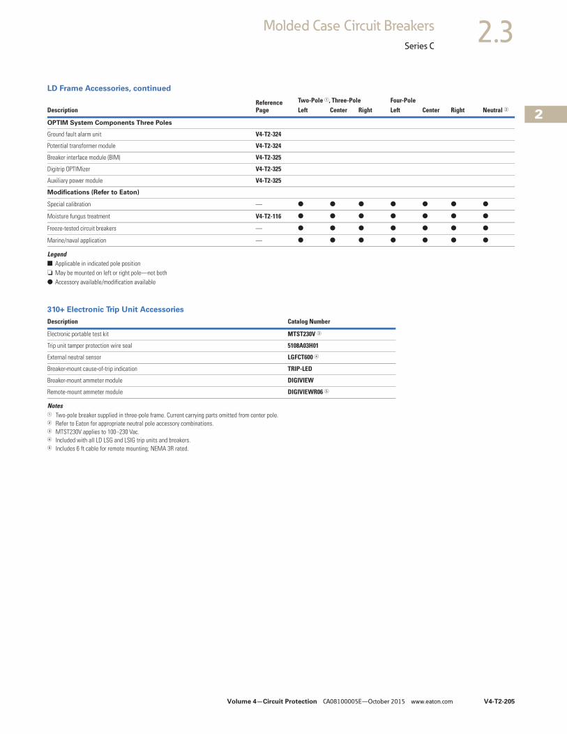
Volume 4—Circuit Protection CA08100005E—October 2015 www.eaton.com V4-T2-205
2
2
2
2
2
2
2
2
2
2
2
2
2
2
2
2
2
2
2
2
2
2
2
2
2
2
2
2
2
2
2.3Molded Case Circuit Breakers
Series C
LD Frame Accessories, continued
Legend■ Applicable in indicated pole position❏ May be mounted on left or right pole—not both● Accessory available/modification available
310+ Electronic Trip Unit Accessories
Notes1 Two-pole breaker supplied in three-pole frame. Current carrying parts omitted from center pole.2 Refer to Eaton for appropriate neutral pole accessory combinations.3 MTST230V applies to 100–230 Vac.4 Included with all LD LSG and LSIG trip units and breakers.5 Includes 6 ft cable for remote mounting; NEMA 3R rated.
DescriptionReference Page
Two-Pole 1, Three-Pole Four-PoleLeft Center Right Left Center Right Neutral 2
OPTIM System Components Three Poles
Ground fault alarm unit V4-T2-324
Potential transformer module V4-T2-324
Breaker interface module (BIM) V4-T2-325
Digitrip OPTIMizer V4-T2-325
Auxiliary power module V4-T2-325
Modifications (Refer to Eaton)
Special calibration — ● ● ● ● ● ● ●
Moisture fungus treatment V4-T2-116 ● ● ● ● ● ● ●
Freeze-tested circuit breakers — ● ● ● ● ● ● ●
Marine/naval application — ● ● ● ● ● ● ●
Description Catalog Number
Electronic portable test kit MTST230V 3
Trip unit tamper protection wire seal 5108A03H01
External neutral sensor LGFCT600 4
Breaker-mount cause-of-trip indication TRIP-LED
Breaker-mount ammeter module DIGIVIEW
Remote-mount ammeter module DIGIVIEWR06 5
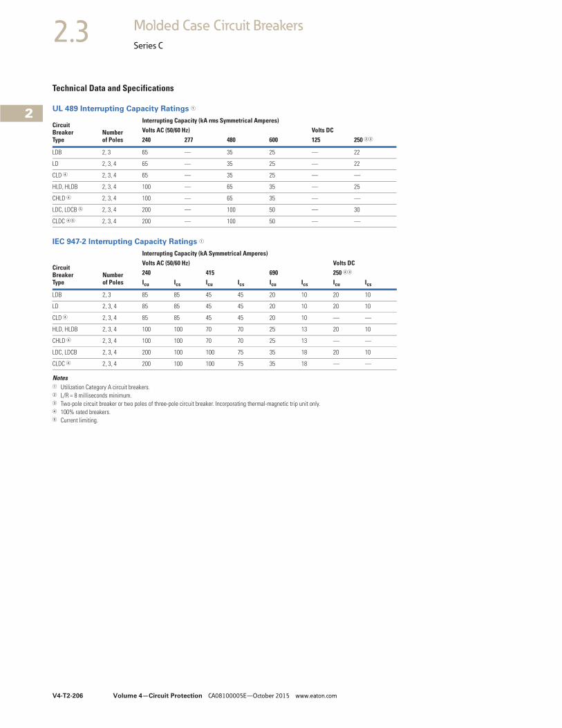
V4-T2-206 Volume 4—Circuit Protection CA08100005E—October 2015 www.eaton.com
2
2
2
2
2
2
2
2
2
2
2
2
2
2
2
2
2
2
2
2
2
2
2
2
2
2
2
2
2
2
2.3 Molded Case Circuit Breakers
Series C
Technical Data and Specifications
UL 489 Interrupting Capacity Ratings 1
IEC 947-2 Interrupting Capacity Ratings 1
Notes1 Utilization Category A circuit breakers.2 L/R = 8 milliseconds minimum.3 Two-pole circuit breaker or two poles of three-pole circuit breaker. Incorporating thermal-magnetic trip unit only.4 100% rated breakers.5 Current limiting.
CircuitBreakerType
Numberof Poles
Interrupting Capacity (kA rms Symmetrical Amperes)Volts AC (50/60 Hz) Volts DC240 277 480 600 125 250 23
LDB 2, 3 65 — 35 25 — 22
LD 2, 3, 4 65 — 35 25 — 22
CLD 4 2, 3, 4 65 — 35 25 — —
HLD, HLDB 2, 3, 4 100 — 65 35 — 25
CHLD 4 2, 3, 4 100 — 65 35 — —
LDC, LDCB 5 2, 3, 4 200 — 100 50 — 30
CLDC 45 2, 3, 4 200 — 100 50 — —
CircuitBreakerType
Numberof Poles
Interrupting Capacity (kA Symmetrical Amperes)Volts AC (50/60 Hz) Volts DC240 415 690 250 23
Icu Ics Icu Ics Icu Ics Icu Ics
LDB 2, 3 85 85 45 45 20 10 20 10
LD 2, 3, 4 85 85 45 45 20 10 20 10
CLD 4 2, 3, 4 85 85 45 45 20 10 — —
HLD, HLDB 2, 3, 4 100 100 70 70 25 13 20 10
CHLD 4 2, 3, 4 100 100 70 70 25 13 — —
LDC, LDCB 2, 3, 4 200 100 100 75 35 18 20 10
CLDC 4 2, 3, 4 200 100 100 75 35 18 — —
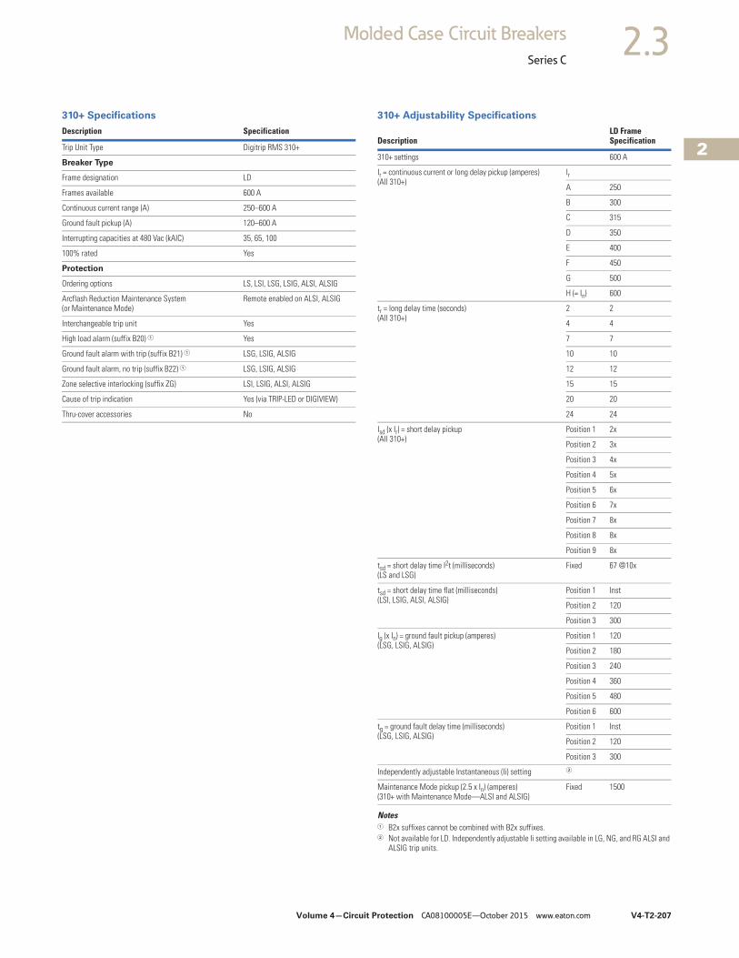
Volume 4—Circuit Protection CA08100005E—October 2015 www.eaton.com V4-T2-207
2
2
2
2
2
2
2
2
2
2
2
2
2
2
2
2
2
2
2
2
2
2
2
2
2
2
2
2
2
2
2.3Molded Case Circuit Breakers
Series C
310+ Specifications 310+ Adjustability Specifications
Notes1 B2x suffixes cannot be combined with B2x suffixes.2 Not available for LD. Independently adjustable Ii setting available in LG, NG, and RG ALSI and
ALSIG trip units.
Description Specification
Trip Unit Type Digitrip RMS 310+
Breaker Type
Frame designation LD
Frames available 600 A
Continuous current range (A) 250–600 A
Ground fault pickup (A) 120–600 A
Interrupting capacities at 480 Vac (kAIC) 35, 65, 100
100% rated Yes
Protection
Ordering options LS, LSI, LSG, LSIG, ALSI, ALSIG
Arcflash Reduction Maintenance System (or Maintenance Mode)
Remote enabled on ALSI, ALSIG
Interchangeable trip unit Yes
High load alarm (suffix B20) 1 Yes
Ground fault alarm with trip (suffix B21) 1 LSG, LSIG, ALSIG
Ground fault alarm, no trip (suffix B22) 1 LSG, LSIG, ALSIG
Zone selective interlocking (suffix ZG) LSI, LSIG, ALSI, ALSIG
Cause of trip indication Yes (via TRIP-LED or DIGIVIEW)
Thru-cover accessories No
DescriptionLD FrameSpecification
310+ settings 600 A
Ir = continuous current or long delay pickup (amperes) (All 310+)
Ir
A 250
B 300
C 315
D 350
E 400
F 450
G 500
H (= In) 600
tr = long delay time (seconds)(All 310+)
2 2
4 4
7 7
10 10
12 12
15 15
20 20
24 24
Isd (x Ir) = short delay pickup(All 310+)
Position 1 2x
Position 2 3x
Position 3 4x
Position 4 5x
Position 5 6x
Position 6 7x
Position 7 8x
Position 8 8x
Position 9 8x
tsd = short delay time I2t (milliseconds)(LS and LSG)
Fixed 67 @10x
tsd = short delay time flat (milliseconds)(LSI, LSIG, ALSI, ALSIG)
Position 1 Inst
Position 2 120
Position 3 300
Ig (x In) = ground fault pickup (amperes)(LSG, LSIG, ALSIG)
Position 1 120
Position 2 180
Position 3 240
Position 4 360
Position 5 480
Position 6 600
tg = ground fault delay time (milliseconds)(LSG, LSIG, ALSIG)
Position 1 Inst
Position 2 120
Position 3 300
Independently adjustable Instantaneous (Ii) setting 2
Maintenance Mode pickup (2.5 x In) (amperes)(310+ with Maintenance Mode—ALSI and ALSIG)
Fixed 1500
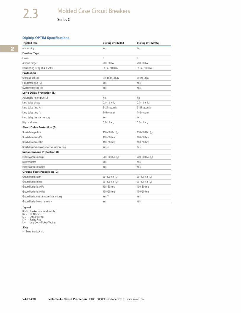
V4-T2-208 Volume 4—Circuit Protection CA08100005E—October 2015 www.eaton.com
2
2
2
2
2
2
2
2
2
2
2
2
2
2
2
2
2
2
2
2
2
2
2
2
2
2
2
2
2
2
2.3 Molded Case Circuit Breakers
Series C
Digitrip OPTIM Specifications
LegendBIM = Breaker Interface Module(A) = GF AlarmIs = Sensor RatingIn = Rating PlugIr = Long Delay Pickup Setting
Note1 Zone interlock kit.
Trip Unit Type Digitrip OPTIM 550 Digitrip OPTIM 1050
rms sensing Yes Yes
Breaker Type
Frame L L
Ampere range 200–600 A 200–600 A
Interrupting rating at 480 volts 35, 65, 100 (kA) 35, 65, 100 (kA)
Protection
Ordering options LSI, LSI(A), LSIG LSI(A), LSIG
Fixed rated plug (In) Yes Yes
Overtemperature trip Yes Yes
Long Delay Protection (L)
Adjustable rating plug (In) No No
Long delay pickup 0.4–1.0 x (In) 0.4–1.0 x (In)
Long delay time I2t 2–24 seconds 2–24 seconds
Long delay time I4t 1–5 seconds 1–5 seconds
Long delay thermal memory Yes Yes
High load alarm 0.5–1.0 x Ir 0.5–1.0 x Ir
Short Delay Protection (S)
Short delay pickup 150–800% x (Ir) 150–800% x (Ir)
Short delay time I2t 100–500 ms 100–500 ms
Short delay time flat 100–500 ms 100–500 ms
Short delay time zone selective interlocking Yes 1 Yes
Instantaneous Protection (I)
Instantaneous pickup 200–800% x (In) 200–800% x (In)
Discriminator Yes Yes
Instantaneous override Yes Yes
Ground Fault Protection (G)
Ground fault alarm 20–100% x (Is) 20–100% x (Is)
Ground fault pickup 20–100% x (Is) 20–100% x (Is)
Ground fault delay I2t 100–500 ms 100–500 ms
Ground fault delay flat 100–500 ms 100–500 ms
Ground fault zone selective interlocking Yes 1 Yes
Ground fault thermal memory Yes Yes
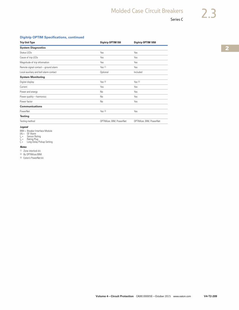
Volume 4—Circuit Protection CA08100005E—October 2015 www.eaton.com V4-T2-209
2
2
2
2
2
2
2
2
2
2
2
2
2
2
2
2
2
2
2
2
2
2
2
2
2
2
2
2
2
2
2.3Molded Case Circuit Breakers
Series C
Digitrip OPTIM Specifications, continued
LegendBIM = Breaker Interface Module(A) = GF AlarmIs = Sensor RatingIn = Rating PlugIr = Long Delay Pickup Setting
Notes1 Zone interlock kit.2 By OPTIMizer/BIM.3 Eaton’s PowerNet kit.
Trip Unit Type Digitrip OPTIM 550 Digitrip OPTIM 1050
System Diagnostics
Status LEDs Yes Yes
Cause of trip LEDs Yes Yes
Magnitude of trip information Yes Yes
Remote signal contact—ground alarm Yes 1 Yes
Local auxiliary and bell alarm contact Optional Included
System Monitoring
Digital display Yes 2 Yes 2
Current Yes Yes
Power and energy No Yes
Power quality—harmonics No Yes
Power factor No Yes
Communications
PowerNet Yes 3 Yes
Testing
Testing method OPTIMizer, BIM, PowerNet OPTIMizer, BIM, PowerNet
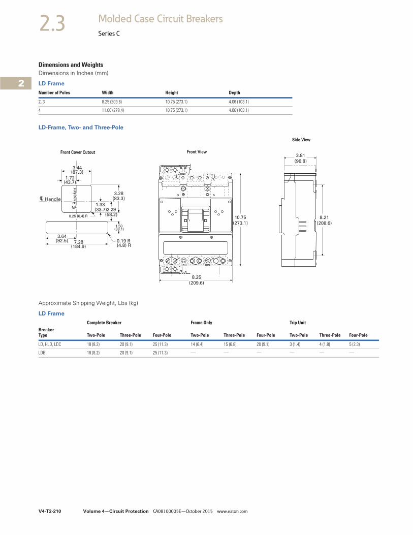
V4-T2-210 Volume 4—Circuit Protection CA08100005E—October 2015 www.eaton.com
2
2
2
2
2
2
2
2
2
2
2
2
2
2
2
2
2
2
2
2
2
2
2
2
2
2
2
2
2
2
2.3 Molded Case Circuit Breakers
Series C
Dimensions and WeightsDimensions in Inches (mm)
LD Frame
LD-Frame, Two- and Three-Pole
Approximate Shipping Weight, Lbs (kg)
LD Frame
Number of Poles Width Height Depth
2, 3 8.25 (209.6) 10.75 (273.1) 4.06 (103.1)
4 11.00 (279.4) 10.75 (273.1) 4.06 (103.1)
10.75
(273.1)
8.25
(209.6)
3.81
(96.8)
8.21
(208.6)
Handle
7.28(184.9)
0.19 R(4.8) R
3.64(92.5)
1.50(38.1)
2.29(58.2)
1.33(33.7)
1.72(43.7)
3.44(87.3)
3.28(83.3)
0.25 (6.4) R
Bre
ake
r
CL
C L
Front View
Side View
Front Cover Cutout
Complete Breaker Frame Only Trip UnitBreaker Type Two-Pole Three-Pole Four-Pole Two-Pole Three-Pole Four-Pole Two-Pole Three-Pole Four-Pole
LD, HLD, LDC 18 (8.2) 20 (9.1) 25 (11.3) 14 (6.4) 15 (6.8) 20 (9.1) 3 (1.4) 4 (1.8) 5 (2.3)
LDB 18 (8.2) 20 (9.1) 25 (11.3) — — — — — —
Volume 4—Circuit Protection CA08100005E—October 2015 www.eaton.com V4-T2-211
2
2
2
2
2
2
2
2
2
2
2
2
2
2
2
2
2
2
2
2
2
2
2
2
2
2
2
2
2
2
2.3Molded Case Circuit Breakers
Series C
Typical M-Frame Circuit Breaker ContentsDescription Page
Product Overview . . . . . . . . . . . . . . . . . . . . . . . . . . V4-T2-116
Standards and Certifications . . . . . . . . . . . . . . . . . . V4-T2-117
Quick Reference . . . . . . . . . . . . . . . . . . . . . . . . . . . V4-T2-118
G-Frame (15–100 Amperes) . . . . . . . . . . . . . . . . . . . V4-T2-121
F-Frame (10–225 Amperes) . . . . . . . . . . . . . . . . . . . V4-T2-135
J-Frame (70–250 Amperes) . . . . . . . . . . . . . . . . . . . V4-T2-153
K-Frame (70–400 Amperes) . . . . . . . . . . . . . . . . . . . V4-T2-161
L-Frame (125–600 Amperes) . . . . . . . . . . . . . . . . . . V4-T2-185
M-Frame (300–800 Amperes)Catalog Number Selection . . . . . . . . . . . . . . . . . V4-T2-212
Product Selection . . . . . . . . . . . . . . . . . . . . . . . . V4-T2-213
Accessories . . . . . . . . . . . . . . . . . . . . . . . . . . . . V4-T2-218
Technical Data and Specifications. . . . . . . . . . . . V4-T2-219
Dimensions and Weights . . . . . . . . . . . . . . . . . . V4-T2-221
Motor Circuit Protectors (MCP) . . . . . . . . . . . . . . . . V4-T2-256
N-Frame (400–1200 Amperes). . . . . . . . . . . . . . . . . V4-T2-222R-Frame (800–2500 Amperes) . . . . . . . . . . . . . . . . . V4-T2-237
Motor Protection Circuit Breakers (MPCB) . . . . . . . V4-T2-267
Type ELC Current Limiter Attachment (Size 0–4) . . . . . V4-T2-269
Current Limiting Circuit Breaker Module. . . . . . . . . . . V4-T2-270Internal Accessories. . . . . . . . . . . . . . . . . . . . . . . . . V4-T2-273External Accessories . . . . . . . . . . . . . . . . . . . . . . . . V4-T2-304
M-Frame (300–800 Amperes)Product Description● All Eaton M-Frame circuit
breakers are HACR rated● MDL-Frame circuit
breakers are available as individual components (frame, trip unit, terminals), or factory assembled complete breakers
● MDLB, HMDLB-Frame circuit breakers with non-interchangeable trip units are suitable for reverse feed use
Standards and Certifications● CE marked

V4-T2-212 Volume 4—Circuit Protection CA08100005E—October 2015 www.eaton.com
2
2
2
2
2
2
2
2
2
2
2
2
2
2
2
2
2
2
2
2
2
2
2
2
2
2
2
2
2
2
2.3 Molded Case Circuit Breakers
Series C
Catalog Number SelectionThis information is presented only as an aid to understanding catalog numbers. It is not to be used to build catalog numbers for circuit breakers or trip units.
MDL Frame with Thermal-Magnetic Trip Unit Technology
Thermal-Magnetic Breakers and Frame 1
Thermal-Magnetic Trip Unit 1
MDL Frame with 310+ Electronic Trip Unit Technology
310+ Circuit Breaker
310+ Electronic Trip Unit 1
Note1 Frames are the same for thermal-magnetic or 310+ electronic trip units, e.g., MDL3800F, HMDL3800F, etc.
Number of Poles
2 = Two-pole3 = Three-pole
Circuit Breaker/Frame Ampere Rating
300 1350 1400450
500600700800
Circuit Breaker/Frame Type
MDL, MDLBHMDL, HMDLB
SuffixF = Frame only (800 A only)K = High magnetic molded case switchV = 50 °C (thermal-magnetic trip units only)W = Without terminalsX = Load side terminals onlyY = Line side terminals only
MDL 3 800 F
Trip Unit TypeMT Number
of Poles2 = Two-pole3 = Three-pole
Trip Unit Rating/Plug Ampere Rating
300 1350 1400450
500600700800
SuffixT = Thermal-magneticV = 50 °C (thermal-magnetic trip units only)
MT 3 800 T
MDLB 3 800 F T36 B21 W
Performance at 480 VacMDLB = 50 kAICHMDLB = 65 kAICCMDLB = 50 kAIC, 100% ratedCHMDLB = 65 kAIC, 100% rated
Number of Poles
3 = Three-pole
TerminalsW = No terminals
Amperes800
DesignationF
FeaturesBlank = No featureB20 = High load alarmB21 = Ground fault alarm, with tripB22 = Ground fault alarm, no tripZG = Zone selective interlocking
Trip UnitT33 = 310+ Electronic LST32 = 310+ Electronic LSIT35 = 310+ Electronic LSGT36 = 310+ Electronic LSIGT38 = 310+ Electronic LSI with Maintenance ModeT39 = 310+ Electronic LSIG with Maintenance Mode
MES 3 800 ALSIG B21
Trip Unit TypeMES Number
of Poles3 = Three-pole Amperes
800
FeaturesBlank = No featureB20 = High load alarmB21 = Ground fault alarm, with tripB22 = Ground fault alarm, no tripZG = Zone selective interlocking
Trip UnitLS = 310+ Electronic LSLSI = 310+ Electronic LSILSG = 310+ Electronic LSGLSIG = 310+ Electronic LSIGALSI = 310+ Electronic LSI with Maintenance ModeALSIG = 310+ Electronic LSIG with Maintenance Mode
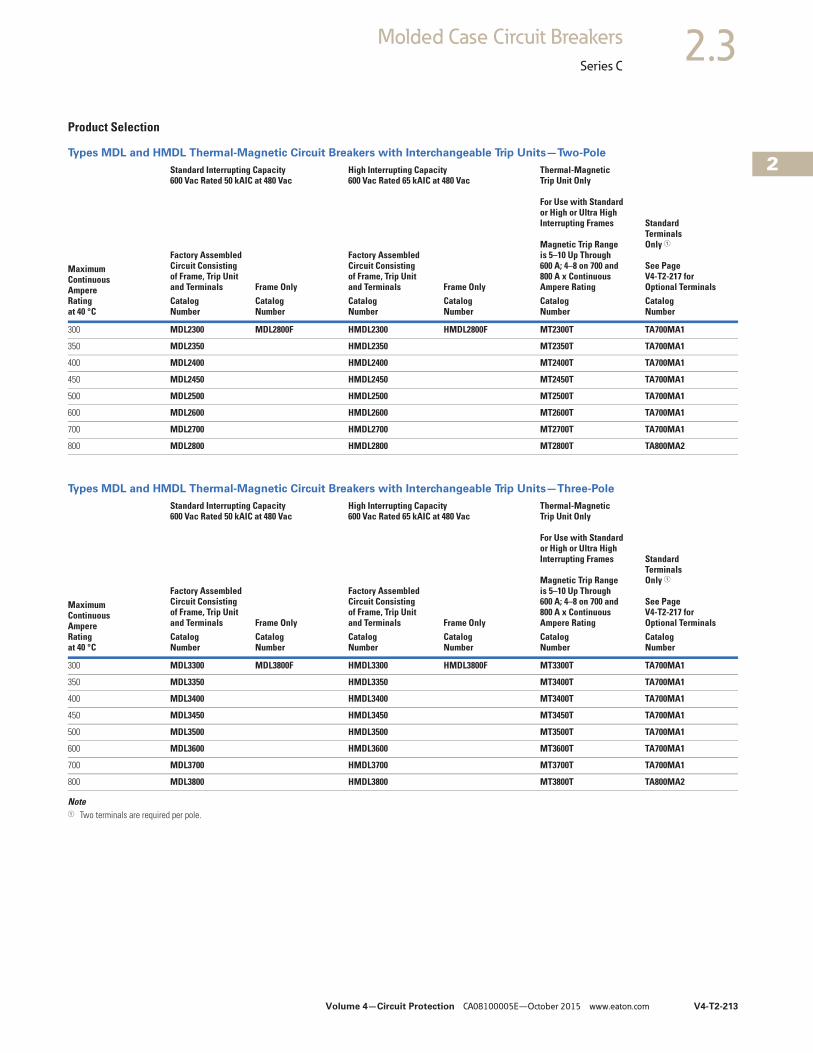
Volume 4—Circuit Protection CA08100005E—October 2015 www.eaton.com V4-T2-213
2
2
2
2
2
2
2
2
2
2
2
2
2
2
2
2
2
2
2
2
2
2
2
2
2
2
2
2
2
2
2.3Molded Case Circuit Breakers
Series C
Product Selection
Types MDL and HMDL Thermal-Magnetic Circuit Breakers with Interchangeable Trip Units—Two-Pole
Types MDL and HMDL Thermal-Magnetic Circuit Breakers with Interchangeable Trip Units—Three-Pole
Note1 Two terminals are required per pole.
MaximumContinuousAmpereRatingat 40 °C
Standard Interrupting Capacity600 Vac Rated 50 kAIC at 480 Vac
High Interrupting Capacity 600 Vac Rated 65 kAIC at 480 Vac
Thermal-MagneticTrip Unit Only
For Use with Standardor High or Ultra High Interrupting Frames
Magnetic Trip Rangeis 5–10 Up Through600 A; 4–8 on 700 and 800 A x ContinuousAmpere Rating
Standard TerminalsOnly 1
See PageV4-T2-217 forOptional Terminals
Factory AssembledCircuit Consistingof Frame, Trip Unitand Terminals Frame Only
Factory AssembledCircuit Consistingof Frame, Trip Unitand Terminals Frame Only
CatalogNumber
CatalogNumber
CatalogNumber
CatalogNumber
CatalogNumber
CatalogNumber
300 MDL2300 MDL2800F HMDL2300 HMDL2800F MT2300T TA700MA1
350 MDL2350 HMDL2350 MT2350T TA700MA1
400 MDL2400 HMDL2400 MT2400T TA700MA1
450 MDL2450 HMDL2450 MT2450T TA700MA1
500 MDL2500 HMDL2500 MT2500T TA700MA1
600 MDL2600 HMDL2600 MT2600T TA700MA1
700 MDL2700 HMDL2700 MT2700T TA700MA1
800 MDL2800 HMDL2800 MT2800T TA800MA2
MaximumContinuousAmpereRatingat 40 °C
Standard Interrupting Capacity600 Vac Rated 50 kAIC at 480 Vac
High Interrupting Capacity 600 Vac Rated 65 kAIC at 480 Vac
Thermal-MagneticTrip Unit Only
For Use with Standardor High or Ultra High Interrupting Frames
Magnetic Trip Rangeis 5–10 Up Through600 A; 4–8 on 700 and 800 A x ContinuousAmpere Rating
Standard TerminalsOnly 1
See Page V4-T2-217 forOptional Terminals
Factory AssembledCircuit Consistingof Frame, Trip Unitand Terminals Frame Only
Factory AssembledCircuit Consistingof Frame, Trip Unitand Terminals Frame Only
CatalogNumber
CatalogNumber
CatalogNumber
CatalogNumber
CatalogNumber
CatalogNumber
300 MDL3300 MDL3800F HMDL3300 HMDL3800F MT3300T TA700MA1
350 MDL3350 HMDL3350 MT3400T TA700MA1
400 MDL3400 HMDL3400 MT3400T TA700MA1
450 MDL3450 HMDL3450 MT3450T TA700MA1
500 MDL3500 HMDL3500 MT3500T TA700MA1
600 MDL3600 HMDL3600 MT3600T TA700MA1
700 MDL3700 HMDL3700 MT3700T TA700MA1
800 MDL3800 HMDL3800 MT3800T TA800MA2
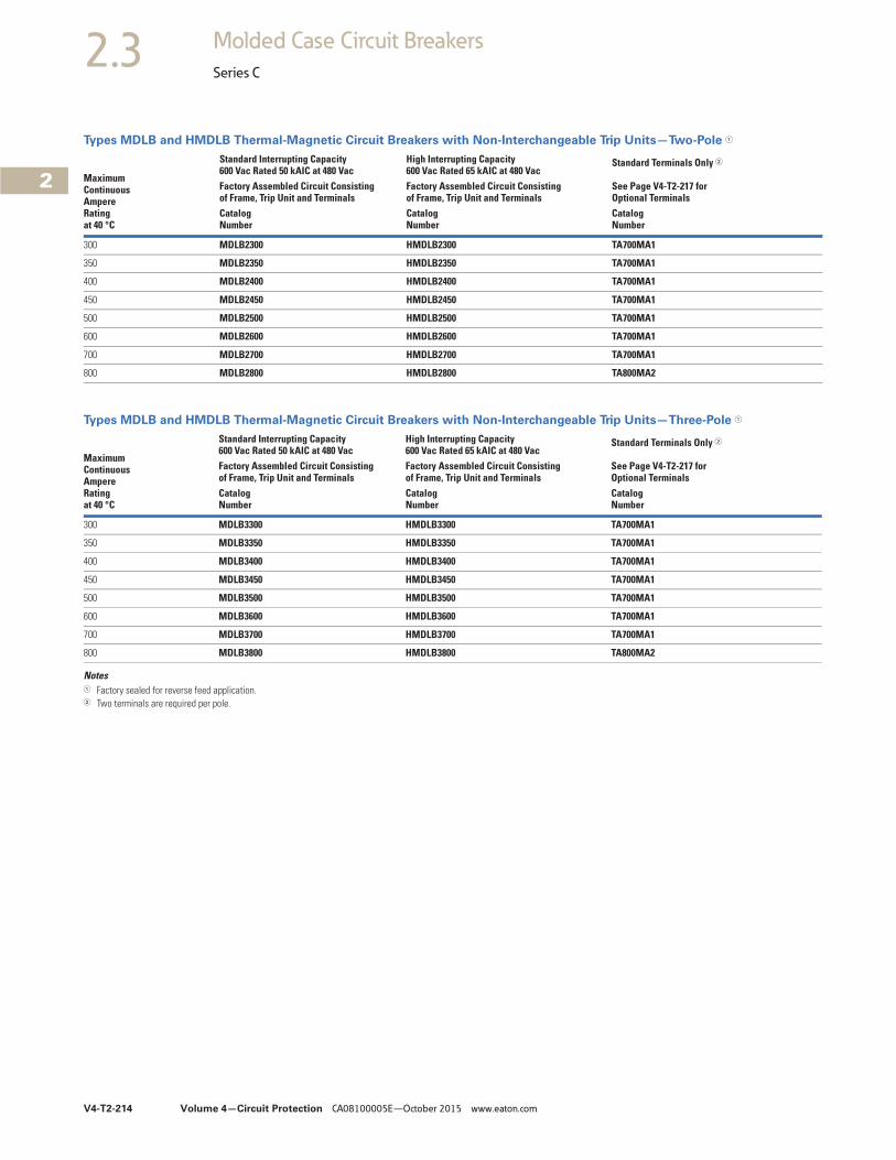
V4-T2-214 Volume 4—Circuit Protection CA08100005E—October 2015 www.eaton.com
2
2
2
2
2
2
2
2
2
2
2
2
2
2
2
2
2
2
2
2
2
2
2
2
2
2
2
2
2
2
2.3 Molded Case Circuit Breakers
Series C
Types MDLB and HMDLB Thermal-Magnetic Circuit Breakers with Non-Interchangeable Trip Units—Two-Pole 1
Types MDLB and HMDLB Thermal-Magnetic Circuit Breakers with Non-Interchangeable Trip Units—Three-Pole 1
Notes1 Factory sealed for reverse feed application.2 Two terminals are required per pole.
Maximum ContinuousAmpereRatingat 40 °C
Standard Interrupting Capacity600 Vac Rated 50 kAIC at 480 Vac
High Interrupting Capacity 600 Vac Rated 65 kAIC at 480 Vac
Standard Terminals Only 2
See Page V4-T2-217 for Optional Terminals
Factory Assembled Circuit Consistingof Frame, Trip Unit and Terminals
Factory Assembled Circuit Consisting of Frame, Trip Unit and Terminals
CatalogNumber
CatalogNumber
CatalogNumber
300 MDLB2300 HMDLB2300 TA700MA1
350 MDLB2350 HMDLB2350 TA700MA1
400 MDLB2400 HMDLB2400 TA700MA1
450 MDLB2450 HMDLB2450 TA700MA1
500 MDLB2500 HMDLB2500 TA700MA1
600 MDLB2600 HMDLB2600 TA700MA1
700 MDLB2700 HMDLB2700 TA700MA1
800 MDLB2800 HMDLB2800 TA800MA2
Maximum ContinuousAmpereRatingat 40 °C
Standard Interrupting Capacity600 Vac Rated 50 kAIC at 480 Vac
High Interrupting Capacity 600 Vac Rated 65 kAIC at 480 Vac
Standard Terminals Only 2
See Page V4-T2-217 for Optional Terminals
Factory Assembled Circuit Consistingof Frame, Trip Unit and Terminals
Factory Assembled Circuit Consisting of Frame, Trip Unit and Terminals
CatalogNumber
CatalogNumber
CatalogNumber
300 MDLB3300 HMDLB3300 TA700MA1
350 MDLB3350 HMDLB3350 TA700MA1
400 MDLB3400 HMDLB3400 TA700MA1
450 MDLB3450 HMDLB3450 TA700MA1
500 MDLB3500 HMDLB3500 TA700MA1
600 MDLB3600 HMDLB3600 TA700MA1
700 MDLB3700 HMDLB3700 TA700MA1
800 MDLB3800 HMDLB3800 TA800MA2
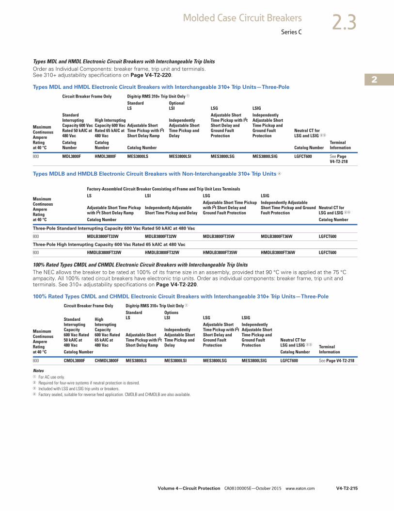
Volume 4—Circuit Protection CA08100005E—October 2015 www.eaton.com V4-T2-215
2
2
2
2
2
2
2
2
2
2
2
2
2
2
2
2
2
2
2
2
2
2
2
2
2
2
2
2
2
2
2.3Molded Case Circuit Breakers
Series C
Types MDL and HMDL Electronic Circuit Breakers with Interchangeable Trip UnitsOrder as Individual Components: breaker frame, trip unit and terminals. See 310+ adjustability specifications on Page V4-T2-220.
Types MDL and HMDL Electronic Circuit Breakers with Interchangeable 310+ Trip Units—Three-Pole
Types MDLB and HMDLB Electronic Circuit Breakers with Non-Interchangeable 310+ Trip Units 4
100% Rated Types CMDL and CHMDL Electronic Circuit Breakers with Interchangeable Trip UnitsThe NEC allows the breaker to be rated at 100% of its frame size in an assembly, provided that 90 °C wire is applied at the 75 °C ampacity. All 100% rated circuit breakers have electronic trip units. Order as individual components: breaker frame, trip unit and terminals. See 310+ adjustability specifications on Page V4-T2-220.
100% Rated Types CMDL and CHMDL Electronic Circuit Breakers with Interchangeable 310+ Trip Units—Three-Pole
Notes1 For AC use only.2 Required for four-wire systems if neutral protection is desired.3 Included with LSG and LSIG trip units or breakers.4 Factory sealed, suitable for reverse feed application. CMDLB and CHMDLB are also available.
MaximumContinuousAmpereRatingat 40 °C
Circuit Breaker Frame Only Digitrip RMS 310+ Trip Unit Only 1
Terminal Information
Standard Interrupting Capacity 600 Vac Rated 50 kAIC at 480 Vac
High Interrupting Capacity 600 Vac Rated 65 kAIC at 480 Vac
StandardLS
OptionalLSI LSG LSIG
Adjustable Short Time Pickup with I2t Short Delay Ramp
Independently Adjustable Short Time Pickup and Delay
Adjustable Short Time Pickup with I2t Short Delay and Ground Fault Protection
Independently Adjustable Short Time Pickup and Ground Fault Protection
Neutral CT forLSG and LSIG 23
CatalogNumber
CatalogNumber Catalog Number Catalog Number
800 MDL3800F HMDL3800F MES3800LS MES3800LSI MES3800LSG MES3800LSIG LGFCT600 See PageV4-T2-218
Maximum Continuous Ampere Rating at 40 °C
Neutral CT forLSG and LSIG 23
Factory-Assembled Circuit Breaker Consisting of Frame and Trip Unit Less TerminalsLS LSI LSG LSIG
Adjustable Short Time Pickup with I2t Short Delay Ramp
Independently Adjustable Short Time Pickup and Delay
Adjustable Short Time Pickup with I2t Short Delay and Ground Fault Protection
Independently Adjustable Short Time Pickup and Ground Fault Protection
Catalog Number Catalog Number
Three-Pole Standard Interrupting Capacity 600 Vac Rated 50 kAIC at 480 Vac
800 MDLB3800FT33W MDLB3800FT32W MDLB3800FT35W MDLB3800FT36W LGFCT600
Three-Pole High Interrupting Capacity 600 Vac Rated 65 kAIC at 480 Vac
800 HMDLB3800FT33W HMDLB3800FT32W HMDLB3800FT35W HMDLB3800FT36W LGFCT600
MaximumContinuousAmpereRatingat 40 °C
Circuit Breaker Frame Only Digitrip RMS 310+ Trip Unit Only 1
TerminalInformation
Standard Interrupting Capacity 600 Vac Rated 50 kAIC at 480 Vac
High Interrupting Capacity 600 Vac Rated 65 kAIC at 480 Vac
StandardLS
OptionsLSI LSG LSIG
Adjustable Short Time Pickup with I2t Short Delay Ramp
Independently Adjustable Short Time Pickup and Delay
Adjustable Short Time Pickup with I2t Short Delay and Ground Fault Protection
Independently Adjustable Short Time Pickup and Ground Fault Protection
Neutral CT forLSG and LSIG 23
Catalog Number Catalog Number
800 CMDL3800F CHMDL3800F MES3800LS MES3800LSI MES3800LSG MES3800LSIG LGFCT600 See Page V4-T2-218
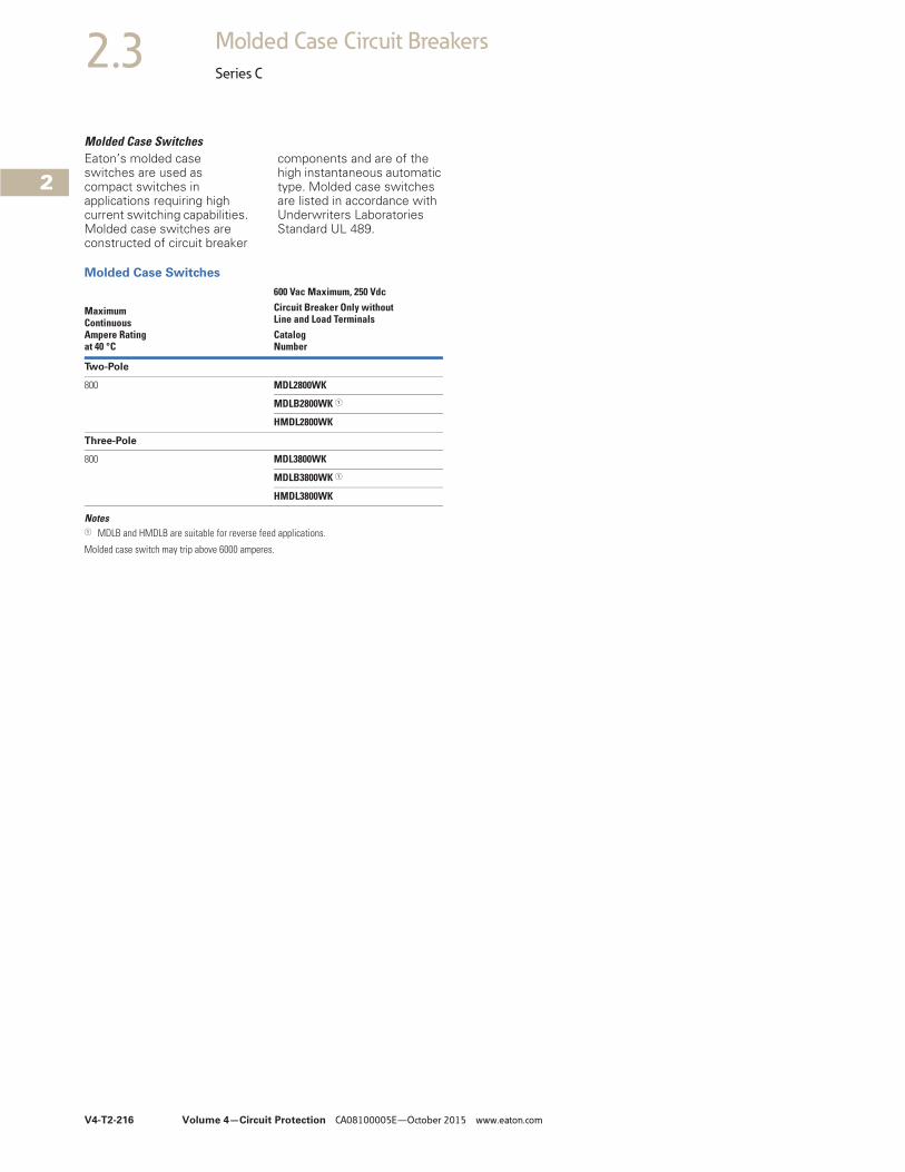
V4-T2-216 Volume 4—Circuit Protection CA08100005E—October 2015 www.eaton.com
2
2
2
2
2
2
2
2
2
2
2
2
2
2
2
2
2
2
2
2
2
2
2
2
2
2
2
2
2
2
2.3 Molded Case Circuit Breakers
Series C
Molded Case SwitchesEaton’s molded case switches are used as compact switches in applications requiring high current switching capabilities. Molded case switches are constructed of circuit breaker
components and are of the high instantaneous automatic type. Molded case switches are listed in accordance with Underwriters Laboratories Standard UL 489.
Molded Case Switches
Notes1 MDLB and HMDLB are suitable for reverse feed applications.
Molded case switch may trip above 6000 amperes.
Maximum ContinuousAmpere Ratingat 40 °C
600 Vac Maximum, 250 VdcCircuit Breaker Only without Line and Load TerminalsCatalog Number
Two-Pole
800 MDL2800WK
MDLB2800WK 1
HMDL2800WK
Three-Pole
800 MDL3800WK
MDLB3800WK 1
HMDL3800WK
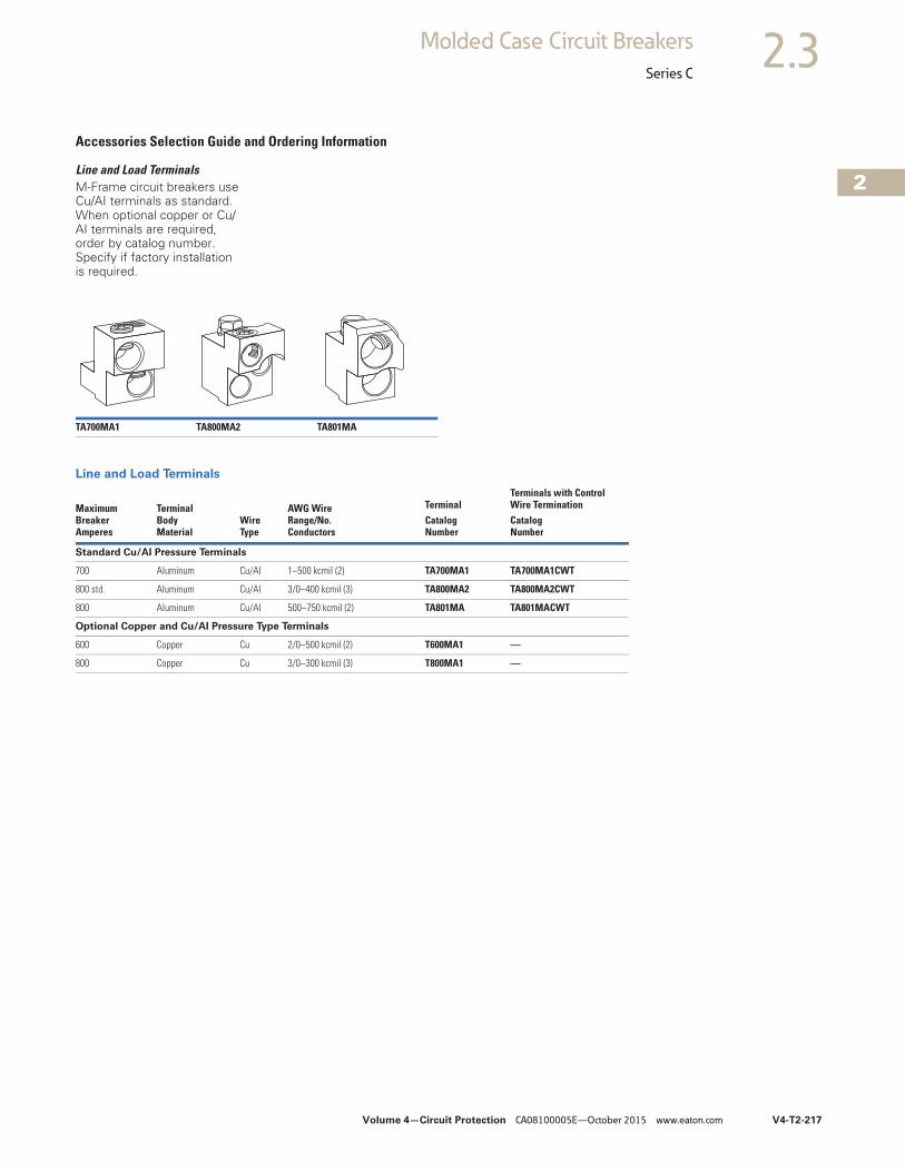
Volume 4—Circuit Protection CA08100005E—October 2015 www.eaton.com V4-T2-217
2
2
2
2
2
2
2
2
2
2
2
2
2
2
2
2
2
2
2
2
2
2
2
2
2
2
2
2
2
2
2.3Molded Case Circuit Breakers
Series C
Accessories Selection Guide and Ordering Information
Line and Load TerminalsM-Frame circuit breakers use Cu/AI terminals as standard. When optional copper or Cu/AI terminals are required, order by catalog number. Specify if factory installation is required.
Line and Load Terminals
TA700MA1 TA800MA2 TA801MA
MaximumBreakerAmperes
TerminalBodyMaterial
Wire Type
AWG WireRange/No.Conductors
TerminalTerminals with ControlWire Termination
CatalogNumber
CatalogNumber
Standard Cu/AI Pressure Terminals
700 Aluminum Cu/AI 1–500 kcmil (2) TA700MA1 TA700MA1CWT
800 std. Aluminum Cu/AI 3/0–400 kcmil (3) TA800MA2 TA800MA2CWT
800 Aluminum Cu/AI 500–750 kcmil (2) TA801MA TA801MACWT
Optional Copper and Cu/AI Pressure Type Terminals
600 Copper Cu 2/0–500 kcmil (2) T600MA1 —
800 Copper Cu 3/0–300 kcmil (3) T800MA1 —
V4-T2-218 Volume 4—Circuit Protection CA08100005E—October 2015 www.eaton.com
2
2
2
2
2
2
2
2
2
2
2
2
2
2
2
2
2
2
2
2
2
2
2
2
2
2
2
2
2
2
2.3 Molded Case Circuit Breakers
Series C
Accessories
Allowable Accessory CombinationsDifferent combinations of accessories can be supplied, depending on the types of accessories and the number of poles in the circuit breaker.
MD Frame Accessories
Legend■ Applicable in indicated pole position❏ May be mounted on left or right pole—not both
● Accessory available/modification available
Notes1 Two-pole breaker supplied in three-pole frame. Current carrying parts omitted from center pole.2 Shunt trip and UVR cannot be mounted in right poles on MES trip units.
DescriptionReference Page
Two-Pole 1 Three-PoleLeft Right Left Center Right
Internal Accessories (Only One Internal Accessory Per Pole)
Alarm lockout (Make/Break) V4-T2-276 ■ ■ ■ ■
Alarm lockout (2Make/2Break) V4-T2-276 ■ ■ ■ ■
Auxiliary switch (1A, 1B) V4-T2-278 ■ ■ ■ ■
Auxiliary switch (2A, 2B) V4-T2-278 ■ ■ ■ ■
Auxiliary switch (3A, 3B) V4-T2-278 ■ ■ ■ ■
Auxiliary switch (1A, 1B) and alarm switch combination V4-T2-280 ■ ■ ■ ■
Auxiliary switch (2A, 2B) and alarm switch combination V4-T2-280 ■ ■ ■ ■
Shunt trip—standard 2 V4-T2-283 ■ ■ ■ ■
Shunt trip—low energy 2 V4-T2-285 ■ ■ ■ ■
Undervoltage release mechanism 2 V4-T2-291 ■ ■ ■ ■
External Accessories
Rear fed terminals V4-T2-310 ● ● ● ● ●
Base mounting hardware V4-T2-311 ●
Terminal shields V4-T2-313 ●
Interphase barriers V4-T2-313 ●
Non-padlockable handle block V4-T2-314 ■
Padlockable handle lock hasp V4-T2-315 ❏ ❏ ❏
Key interlock kit V4-T2-316 ❏ ❏ ❏
Sliding bar interlock—requires two breakers V4-T2-317 ● ● ● ● ●
Walking beam interlock—requires two breakers V4-T2-317 ● ● ● ● ●
Electrical (motor) operator V4-T2-318 ● ● ● ● ●
Plug-in adapters V4-T2-320 ● ● ● ● ●
Rear connecting studs V4-T2-321 ● ● ● ● ●
Panelboard connecting straps V4-T2-322 ● ● ● ● ●
Handle mechanisms V4-T2-430 ● ● ● ● ●
Handle extension V4-T2-445 ● ● ● ● ●
Solid-state (electronic) portable test kit V4-T2-324 ● ● ● ● ●
Modifications (Refer to Eaton)
Special calibration — ● ● ● ● ●
Moisture fungus treatment V4-T2-116 ● ● ● ● ●
Freeze-tested circuit breakers — ● ● ● ● ●
Marine/naval application — ● ● ● ● ●
Volume 4—Circuit Protection CA08100005E—October 2015 www.eaton.com V4-T2-219
2
2
2
2
2
2
2
2
2
2
2
2
2
2
2
2
2
2
2
2
2
2
2
2
2
2
2
2
2
2
2.3Molded Case Circuit Breakers
Series C
310+ Electronic Trip Unit Accessories
Technical Data and Specifications
UL 489/CSA Interrupting Capacity Ratings 4
IEC 947-2 Interrupting Capacity Ratings 4
Notes1 MTST230V applies to 100–230 Vac.2 Included with all LD LSG and LSIG trip units and breakers.3 Includes 6 ft cable for remote mounting; NEMA 3R rated.4 Utilization Category A circuit breakers.5 Two-pole or two poles of three-pole circuit breaker. Thermal-magnetic trip units only, MDL, HMDL breakers with electronic trip unit are not DC rated.6 Time constant is 3 milliseconds minimum at 10 kA and 8 milliseconds at 22 kA.
Description Catalog Number
Electronic portable test kit MTST230V 1
Trip unit tamper protection wire seal 5108A03H01
External neutral sensor LGFCT600 2
Breaker-mount cause-of-trip indication TRIP-LED
Breaker-mount ammeter module DIGIVIEW
Remote-mount ammeter module DIGIVIEWR06 3
CircuitBreakerType
Numberof Poles
Interrupting Capacity (kA Symmetrical Amperes)Volts AC (50/60 Hz) Volts DC 56
240 480 600 250
MDL, MDLB 2, 3 65 50 25 22
CMDL 2, 3 65 50 25 —
HMDL, HMDLB 2, 3 100 65 35 25
CHMDL 2, 3 100 65 35 —
CircuitBreakerType
Numberof Poles
Interrupting Capacity rms (kA Symmetrical Amperes) ICU ≠ ICS
Volts AC (50/60 Hz) Volts DC 56
240 415 690 250
MDL, MDLB 2, 3 65/65 50/50 20/10 20/10
CMDL 2, 3 65/65 50/50 20/10 —
HMDL, HMDLB 2, 3 100/100 70/50 25/13 20/10
CHMDL 2, 3 100/100 70/50 25/13 —
V4-T2-220 Volume 4—Circuit Protection CA08100005E—October 2015 www.eaton.com
2
2
2
2
2
2
2
2
2
2
2
2
2
2
2
2
2
2
2
2
2
2
2
2
2
2
2
2
2
2
2.3 Molded Case Circuit Breakers
Series C
310+ Specifications 310+ Adjustability Specifications
Notes1 B2x suffixes cannot be combined with B2x suffixes.2 Not available for MDL. Independently adjustable Ii setting available in LG, NG, and RG ALSI
and ALSIG trip units.
Description Specification
Trip Unit Type Digitrip RMS 310+
Breaker Type
Frame designation MDL
Frames available 800 A
Continuous current range (A) 320–800 A
Ground fault pickup (A) 160–800 A
Interrupting capacities at 480 Vac (kAIC) 50, 65
100% rated Yes
Protection
Ordering options LS, LSI, LSG, LSIG, ALSI, ALSIG
Arcflash Reduction Maintenance System (or Maintenance Mode)
Remote enabled on ALSI, ALSIG
Interchangeable trip unit Yes
High load alarm (suffix B20) 1 Yes
Ground fault alarm with trip (suffix B21) 1 LSG, LSIG, ALSIG
Ground fault alarm, no trip (suffix B22) 1 LSG, LSIG, ALSIG
Zone selective interlocking (suffix ZG) LSI, LSIG, ALSI, ALSIG
Cause of trip indication Yes (via TRIP-LED or DIGIVIEW)
Thru-cover accessories No
DescriptionMDL FrameSpecification
310+ settings 800 A
Ir = continuous current or long delay pickup (amperes)(All 310+)
Ir
A 320
B 400
C 450
D 500
E 600
F 630
G 700
H (= In) 800
tr = long delay time (seconds)(All 310+)
2 2
4 4
7 7
10 10
12 12
15 15
20 20
24 24
Isd (x Ir) = short delay pickup(All 310+)
Position 1 2x
Position 2 3x
Position 3 4x
Position 4 5x
Position 5 6x
Position 6 7x
Position 7 8x
Position 8 8x
Position 9 8x
tsd = short delay time I2t (milliseconds)(LS and LSG)
Fixed 67 @10x
tsd = short delay time flat (milliseconds)(LSI, LSIG, ALSI, ALSIG)
Position 1 Inst
Position 2 120
Position 3 300
Ig (x In) = ground fault pickup (amperes)(310+ w/ ground fault)
Position 1 160
Position 2 240
Position 3 320
Position 4 480
Position 5 640
Position 6 800
tg = ground fault delay time (milliseconds)(LSG, LSIG, ALSIG)
Position 1 Inst
Position 2 120
Position 3 300
Independently adjustable Instantaneous (Ii) setting 2
Maintenance Mode pickup (2.5 x In) (amperes)(310+ with Maintenance Mode—ALSI and ALSIG)
Fixed 2000
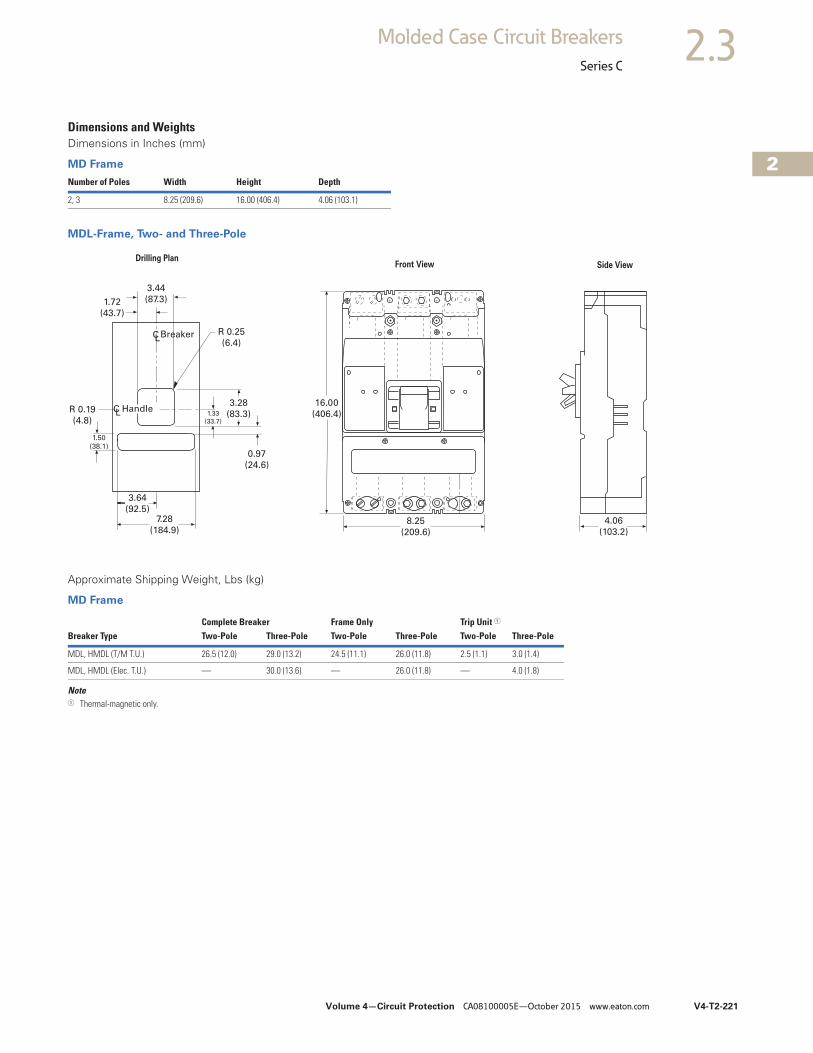
Volume 4—Circuit Protection CA08100005E—October 2015 www.eaton.com V4-T2-221
2
2
2
2
2
2
2
2
2
2
2
2
2
2
2
2
2
2
2
2
2
2
2
2
2
2
2
2
2
2
2.3Molded Case Circuit Breakers
Series C
Dimensions and WeightsDimensions in Inches (mm)
MD Frame
MDL-Frame, Two- and Three-Pole
Approximate Shipping Weight, Lbs (kg)
MD Frame
Note1 Thermal-magnetic only.
Number of Poles Width Height Depth
2, 3 8.25 (209.6) 16.00 (406.4) 4.06 (103.1)
16.00
(406.4)
8.25
(209.6)
4.06
(103.2)
3.44
(87.3)1.72
(43.7)
CLBreaker R 0.25
(6.4)
R 0.19
(4.8)
1.50
(38.1)
3.64
(92.5)7.28
(184.9)
0.97
(24.6)
3.28
(83.3)1.33
(33.7)
HandleCL
Front View Side ViewDrilling Plan
Complete Breaker Frame Only Trip Unit 1
Breaker Type Two-Pole Three-Pole Two-Pole Three-Pole Two-Pole Three-Pole
MDL, HMDL (T/M T.U.) 26.5 (12.0) 29.0 (13.2) 24.5 (11.1) 26.0 (11.8) 2.5 (1.1) 3.0 (1.4)
MDL, HMDL (Elec. T.U.) — 30.0 (13.6) — 26.0 (11.8) — 4.0 (1.8)
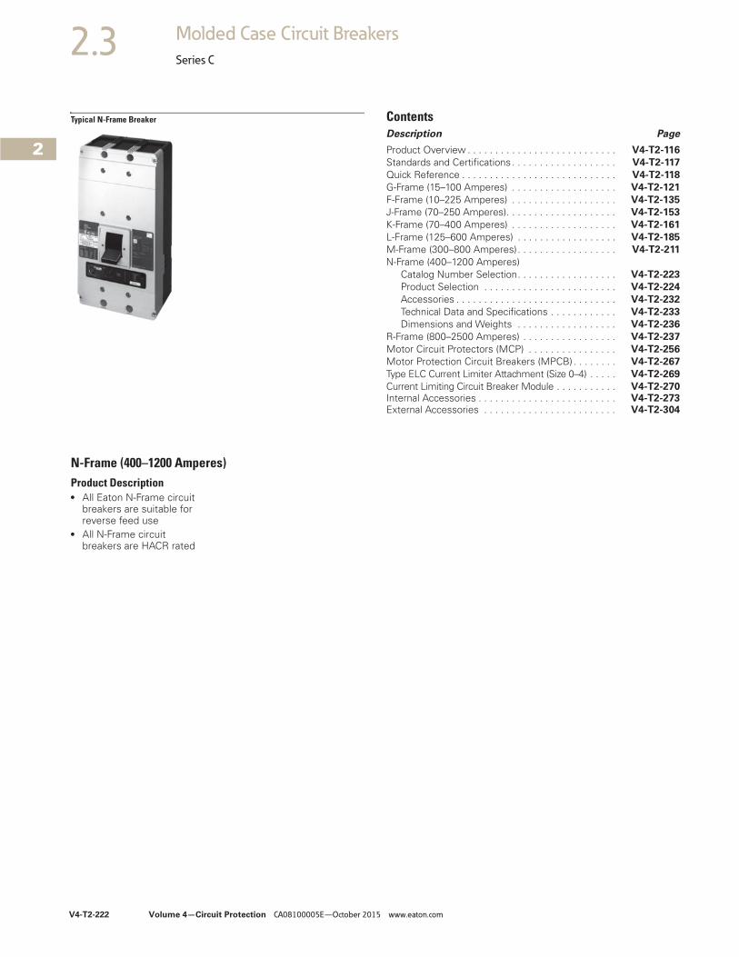
V4-T2-222 Volume 4—Circuit Protection CA08100005E—October 2015 www.eaton.com
2
2
2
2
2
2
2
2
2
2
2
2
2
2
2
2
2
2
2
2
2
2
2
2
2
2
2
2
2
2
2.3 Molded Case Circuit Breakers
Series C
Typical N-Frame Breaker ContentsDescription Page
Product Overview . . . . . . . . . . . . . . . . . . . . . . . . . . . V4-T2-116
Standards and Certifications. . . . . . . . . . . . . . . . . . . V4-T2-117
Quick Reference . . . . . . . . . . . . . . . . . . . . . . . . . . . . V4-T2-118
G-Frame (15–100 Amperes) . . . . . . . . . . . . . . . . . . . V4-T2-121
F-Frame (10–225 Amperes) . . . . . . . . . . . . . . . . . . . V4-T2-135
J-Frame (70–250 Amperes). . . . . . . . . . . . . . . . . . . . V4-T2-153
K-Frame (70–400 Amperes) . . . . . . . . . . . . . . . . . . . V4-T2-161
L-Frame (125–600 Amperes) . . . . . . . . . . . . . . . . . . V4-T2-185
M-Frame (300–800 Amperes). . . . . . . . . . . . . . . . . . V4-T2-211
N-Frame (400–1200 Amperes)Catalog Number Selection. . . . . . . . . . . . . . . . . . V4-T2-223
Product Selection . . . . . . . . . . . . . . . . . . . . . . . . V4-T2-224
Accessories . . . . . . . . . . . . . . . . . . . . . . . . . . . . . V4-T2-232
Technical Data and Specifications . . . . . . . . . . . . V4-T2-233
Dimensions and Weights . . . . . . . . . . . . . . . . . . V4-T2-236
R-Frame (800–2500 Amperes) . . . . . . . . . . . . . . . . . V4-T2-237
Motor Circuit Protectors (MCP) . . . . . . . . . . . . . . . . V4-T2-256
Motor Protection Circuit Breakers (MPCB) . . . . . . . . V4-T2-267
Type ELC Current Limiter Attachment (Size 0–4) . . . . . V4-T2-269
Current Limiting Circuit Breaker Module . . . . . . . . . . . V4-T2-270Internal Accessories . . . . . . . . . . . . . . . . . . . . . . . . . V4-T2-273External Accessories . . . . . . . . . . . . . . . . . . . . . . . . V4-T2-304
N-Frame (400–1200 Amperes)Product Description● All Eaton N-Frame circuit
breakers are suitable for reverse feed use
● All N-Frame circuit breakers are HACR rated
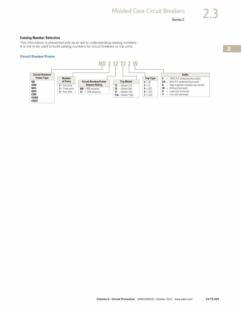
Volume 4—Circuit Protection CA08100005E—October 2015 www.eaton.com V4-T2-223
2
2
2
2
2
2
2
2
2
2
2
2
2
2
2
2
2
2
2
2
2
2
2
2
2
2
2
2
2
2
2.3Molded Case Circuit Breakers
Series C
Catalog Number SelectionThis information is presented only as an aid to understanding catalog numbers. It is not to be used to build catalog numbers for circuit breakers or trip units.
Circuit Breaker/Frame
Circuit Breaker/Frame Type
NDHNDNDCNDUCNDCHNDCNDC
Number of Poles
2 = Two-pole3 = Three-pole4 = Four-pole
Circuit Breaker/Frame Ampere Rating
800 = 800 amperes12 = 1200 amperes
Trip ModelT3 = Model 310T5 = Model 550T7 = Model 750T10 = Model 1050
Trip Type2 = LSI3 = LS5 = LSG6 = LSIG7 = LSIA
SuffixE = 100% R.P. protected (four-pole)EH = 50% R.P. protected (four-pole)K = High magnetic molded case switchW = Without terminalsX = Load only terminalsY = Line only terminals
ND 3 12 T3 2 W
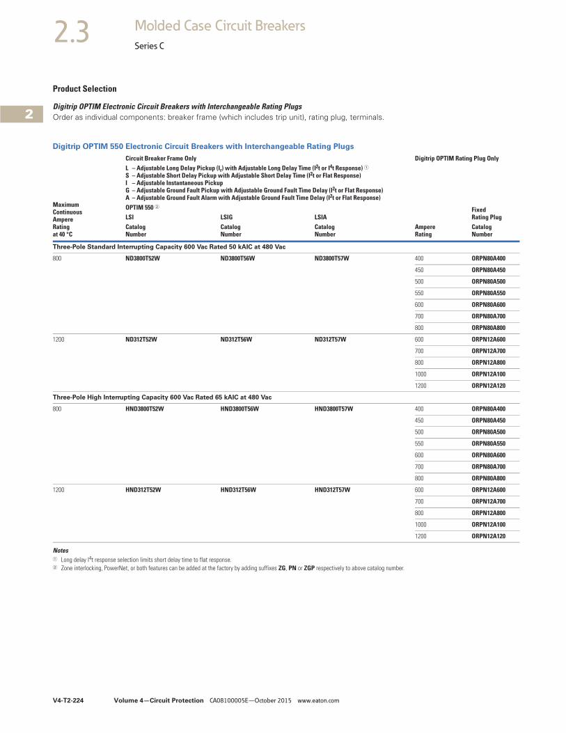
V4-T2-224 Volume 4—Circuit Protection CA08100005E—October 2015 www.eaton.com
2
2
2
2
2
2
2
2
2
2
2
2
2
2
2
2
2
2
2
2
2
2
2
2
2
2
2
2
2
2
2.3 Molded Case Circuit Breakers
Series C
Product Selection
Digitrip OPTIM Electronic Circuit Breakers with Interchangeable Rating PlugsOrder as individual components: breaker frame (which includes trip unit), rating plug, terminals.
Digitrip OPTIM 550 Electronic Circuit Breakers with Interchangeable Rating Plugs
Notes1 Long delay I4t response selection limits short delay time to flat response.2 Zone interlocking, PowerNet, or both features can be added at the factory by adding suffixes ZG, PN or ZGP respectively to above catalog number.
MaximumContinuousAmpereRatingat 40 °C
Circuit Breaker Frame Only Digitrip OPTIM Rating Plug OnlyL – Adjustable Long Delay Pickup (Ir) with Adjustable Long Delay Time (I2t or I4t Response) 1S – Adjustable Short Delay Pickup with Adjustable Short Delay Time (I2t or Flat Response)I – Adjustable Instantaneous Pickup G – Adjustable Ground Fault Pickup with Adjustable Ground Fault Time Delay (I2t or Flat Response)A – Adjustable Ground Fault Alarm with Adjustable Ground Fault Time Delay (I2t or Flat Response)
Ampere Rating
Fixed Rating Plug
OPTIM 550 2
LSI LSIG LSIACatalogNumber
CatalogNumber
CatalogNumber
CatalogNumber
Three-Pole Standard Interrupting Capacity 600 Vac Rated 50 kAIC at 480 Vac
800 ND3800T52W ND3800T56W ND3800T57W 400 ORPN80A400
450 ORPN80A450
500 ORPN80A500
550 ORPN80A550
600 ORPN80A600
700 ORPN80A700
800 ORPN80A800
1200 ND312T52W ND312T56W ND312T57W 600 ORPN12A600
700 ORPN12A700
800 ORPN12A800
1000 ORPN12A100
1200 ORPN12A120
Three-Pole High Interrupting Capacity 600 Vac Rated 65 kAIC at 480 Vac
800 HND3800T52W HND3800T56W HND3800T57W 400 ORPN80A400
450 ORPN80A450
500 ORPN80A500
550 ORPN80A550
600 ORPN80A600
700 ORPN80A700
800 ORPN80A800
1200 HND312T52W HND312T56W HND312T57W 600 ORPN12A600
700 ORPN12A700
800 ORPN12A800
1000 ORPN12A100
1200 ORPN12A120
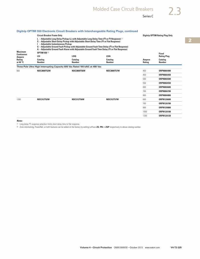
Volume 4—Circuit Protection CA08100005E—October 2015 www.eaton.com V4-T2-225
2
2
2
2
2
2
2
2
2
2
2
2
2
2
2
2
2
2
2
2
2
2
2
2
2
2
2
2
2
2
2.3Molded Case Circuit Breakers
Series C
Digitrip OPTIM 550 Electronic Circuit Breakers with Interchangeable Rating Plugs, continued
Notes1 Long delay I4t response selection limits short delay time to flat response.2 Zone interlocking, PowerNet, or both features can be added at the factory by adding suffixes ZG, PN or ZGP respectively to above catalog number.
MaximumContinuousAmpereRatingat 40 °C
Circuit Breaker Frame Only Digitrip OPTIM Rating Plug OnlyL – Adjustable Long Delay Pickup (Ir) with Adjustable Long Delay Time (I2t or I4t Response) 1S – Adjustable Short Delay Pickup with Adjustable Short Delay Time (I2t or Flat Response)I – Adjustable Instantaneous Pickup G – Adjustable Ground Fault Pickup with Adjustable Ground Fault Time Delay (I2t or Flat Response)A – Adjustable Ground Fault Alarm with Adjustable Ground Fault Time Delay (I2t or Flat Response)
Ampere Rating
Fixed Rating Plug
OPTIM 550 2
LSI LSIG LSIACatalogNumber
CatalogNumber
CatalogNumber
CatalogNumber
Three-Pole Ultra High Interrupting Capacity 600 Vac Rated 100 kAIC at 480 Vac
800 NDC3800T52W NDC3800T56W NDC3800T57W 400 ORPN80A400
450 ORPN80A450
500 ORPN80A500
550 ORPN80A550
600 ORPN80A600
700 ORPN80A700
800 ORPN80A800
1200 NDC312T52W NDC312T56W NDC312T57W 600 ORPN12A600
700 ORPN12A700
800 ORPN12A800
1000 ORPN12A100
1200 ORPN12A120
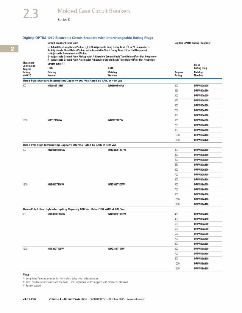
V4-T2-226 Volume 4—Circuit Protection CA08100005E—October 2015 www.eaton.com
2
2
2
2
2
2
2
2
2
2
2
2
2
2
2
2
2
2
2
2
2
2
2
2
2
2
2
2
2
2
2.3 Molded Case Circuit Breakers
Series C
Digitrip OPTIM 1050 Electronic Circuit Breakers with Interchangeable Rating Plugs
Notes1 Long delay I4t response selection limits short delay time to flat response.2 One Form C auxiliary switch and one Form C bell (trip) alarm switch supplied with breaker as standard.3 Factory sealed.
MaximumContinuousAmpereRatingat 40 °C
Circuit Breaker Frame Only Digitrip OPTIM Rating Plug OnlyL– Adjustable Long Delay Pickup (Ir) with Adjustable Long Delay Time (I2t or I4t Response) 1S– Adjustable Short Delay Pickup with Adjustable Short Delay Time (I2t or Flat Response)I– Adjustable Instantaneous Pickup G– Adjustable Ground Fault Pickup with Adjustable Ground Fault Time Delay (I2t or Flat Response)A– Adjustable Ground Fault Alarm with Adjustable Ground Fault Time Delay (I2t or Flat Response)
Ampere Rating
Fixed Rating Plug
OPTIM 1050 23
LSIG LSIACatalogNumber
CatalogNumber
CatalogNumber
Three-Pole Standard Interrupting Capacity 600 Vac Rated 50 kAIC at 480 Vac
800 ND3800T106W ND3800T107W 400 ORPN80A400
450 ORPN80A450
500 ORPN80A500
550 ORPN80A550
600 ORPN80A600
700 ORPN80A700
800 ORPN80A800
1200 ND312T106W ND312T107W 600 ORPN12A600
700 ORPN12A700
800 ORPN12A800
1000 ORPN12A100
1200 ORPN12A120
Three-Pole High Interrupting Capacity 600 Vac Rated 65 kAIC at 480 Vac
800 HND3800T106W HND3800T107W 400 ORPN80A400
450 ORPN80A450
500 ORPN80A500
550 ORPN80A550
600 ORPN80A600
700 ORPN80A700
800 ORPN80A800
1200 HND312T106W HND312T107W 600 ORPN12A600
700 ORPN12A700
800 ORPN12A800
1000 ORPN12A100
1200 ORPN12A120
Three-Pole Ultra High Interrupting Capacity 600 Vac Rated 100 kAIC at 480 Vac
800 NDC3800T106W NDC3800T107W 400 ORPN80A400
450 ORPN80A450
500 ORPN80A500
550 ORPN80A550
600 ORPN80A600
700 ORPN80A700
800 ORPN80A800
1200 NDC312T106W NDC312T107W 600 ORPN12A600
700 ORPN12A700
800 ORPN12A800
1000 ORPN12A100
1200 ORPN12A120
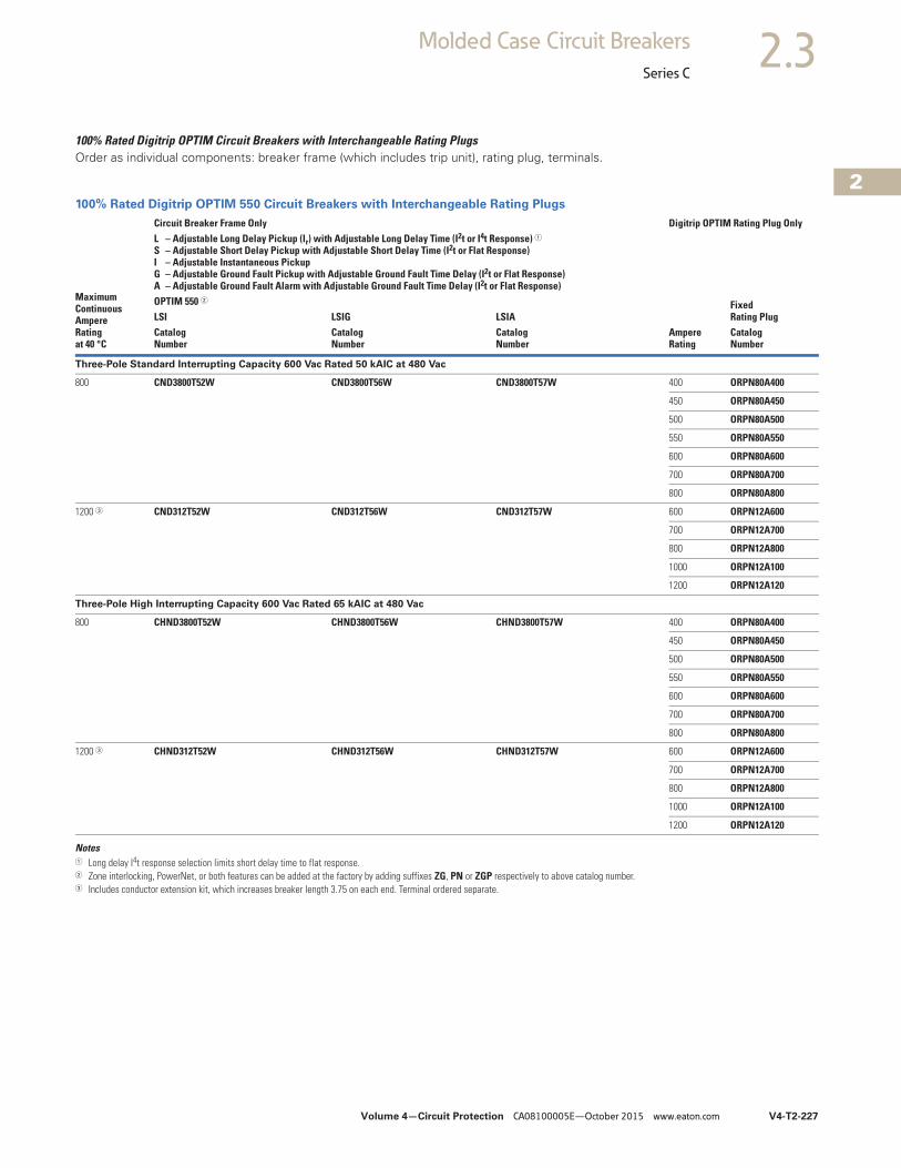
Volume 4—Circuit Protection CA08100005E—October 2015 www.eaton.com V4-T2-227
2
2
2
2
2
2
2
2
2
2
2
2
2
2
2
2
2
2
2
2
2
2
2
2
2
2
2
2
2
2
2.3Molded Case Circuit Breakers
Series C
100% Rated Digitrip OPTIM Circuit Breakers with Interchangeable Rating PlugsOrder as individual components: breaker frame (which includes trip unit), rating plug, terminals.
100% Rated Digitrip OPTIM 550 Circuit Breakers with Interchangeable Rating Plugs
Notes1 Long delay I4t response selection limits short delay time to flat response.2 Zone interlocking, PowerNet, or both features can be added at the factory by adding suffixes ZG, PN or ZGP respectively to above catalog number.3 Includes conductor extension kit, which increases breaker length 3.75 on each end. Terminal ordered separate.
MaximumContinuousAmpereRatingat 40 °C
Circuit Breaker Frame Only Digitrip OPTIM Rating Plug OnlyL – Adjustable Long Delay Pickup (Ir) with Adjustable Long Delay Time (I2t or I4t Response) 1S – Adjustable Short Delay Pickup with Adjustable Short Delay Time (I2t or Flat Response)I – Adjustable Instantaneous Pickup G – Adjustable Ground Fault Pickup with Adjustable Ground Fault Time Delay (I2t or Flat Response)A – Adjustable Ground Fault Alarm with Adjustable Ground Fault Time Delay (I2t or Flat Response)
Ampere Rating
Fixed Rating Plug
OPTIM 550 2
LSI LSIG LSIACatalog Number
Catalog Number
Catalog Number
Catalog Number
Three-Pole Standard Interrupting Capacity 600 Vac Rated 50 kAIC at 480 Vac
800 CND3800T52W CND3800T56W CND3800T57W 400 ORPN80A400
450 ORPN80A450
500 ORPN80A500
550 ORPN80A550
600 ORPN80A600
700 ORPN80A700
800 ORPN80A800
1200 3 CND312T52W CND312T56W CND312T57W 600 ORPN12A600
700 ORPN12A700
800 ORPN12A800
1000 ORPN12A100
1200 ORPN12A120
Three-Pole High Interrupting Capacity 600 Vac Rated 65 kAIC at 480 Vac
800 CHND3800T52W CHND3800T56W CHND3800T57W 400 ORPN80A400
450 ORPN80A450
500 ORPN80A500
550 ORPN80A550
600 ORPN80A600
700 ORPN80A700
800 ORPN80A800
1200 3 CHND312T52W CHND312T56W CHND312T57W 600 ORPN12A600
700 ORPN12A700
800 ORPN12A800
1000 ORPN12A100
1200 ORPN12A120
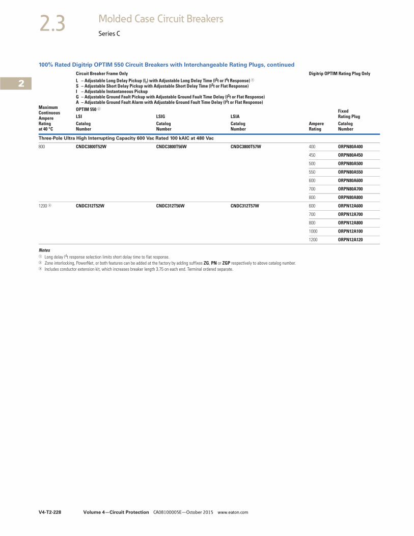
V4-T2-228 Volume 4—Circuit Protection CA08100005E—October 2015 www.eaton.com
2
2
2
2
2
2
2
2
2
2
2
2
2
2
2
2
2
2
2
2
2
2
2
2
2
2
2
2
2
2
2.3 Molded Case Circuit Breakers
Series C
100% Rated Digitrip OPTIM 550 Circuit Breakers with Interchangeable Rating Plugs, continued
Notes1 Long delay I4t response selection limits short delay time to flat response.2 Zone interlocking, PowerNet, or both features can be added at the factory by adding suffixes ZG, PN or ZGP respectively to above catalog number.3 Includes conductor extension kit, which increases breaker length 3.75 on each end. Terminal ordered separate.
MaximumContinuousAmpereRatingat 40 °C
Circuit Breaker Frame Only Digitrip OPTIM Rating Plug OnlyL – Adjustable Long Delay Pickup (Ir) with Adjustable Long Delay Time (I2t or I4t Response) 1S – Adjustable Short Delay Pickup with Adjustable Short Delay Time (I2t or Flat Response)I – Adjustable Instantaneous Pickup G – Adjustable Ground Fault Pickup with Adjustable Ground Fault Time Delay (I2t or Flat Response)A – Adjustable Ground Fault Alarm with Adjustable Ground Fault Time Delay (I2t or Flat Response)
Ampere Rating
Fixed Rating Plug
OPTIM 550 2
LSI LSIG LSIACatalog Number
Catalog Number
Catalog Number
Catalog Number
Three-Pole Ultra High Interrupting Capacity 600 Vac Rated 100 kAIC at 480 Vac
800 CNDC3800T52W CNDC3800T56W CNDC3800T57W 400 ORPN80A400
450 ORPN80A450
500 ORPN80A500
550 ORPN80A550
600 ORPN80A600
700 ORPN80A700
800 ORPN80A800
1200 3 CNDC312T52W CNDC312T56W CNDC312T57W 600 ORPN12A600
700 ORPN12A700
800 ORPN12A800
1000 ORPN12A100
1200 ORPN12A120
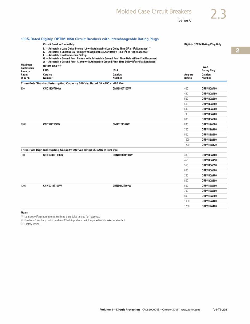
Volume 4—Circuit Protection CA08100005E—October 2015 www.eaton.com V4-T2-229
2
2
2
2
2
2
2
2
2
2
2
2
2
2
2
2
2
2
2
2
2
2
2
2
2
2
2
2
2
2
2.3Molded Case Circuit Breakers
Series C
100% Rated Digitrip OPTIM 1050 Circuit Breakers with Interchangeable Rating Plugs
Notes1 Long delay I4t response selection limits short delay time to flat response.2 One Form C auxiliary switch one Form C bell (trip) alarm switch supplied with breaker as standard.3 Factory sealed.
MaximumContinuousAmpereRatingat 40 °C
Circuit Breaker Frame Only Digitrip OPTIM Rating Plug OnlyL – Adjustable Long Delay Pickup (Ir) with Adjustable Long Delay Time (I2t or I4t Response) 1S – Adjustable Short Delay Pickup with Adjustable Short Delay Time (I2t or Flat Response)I – Adjustable Instantaneous Pickup G – Adjustable Ground Fault Pickup with Adjustable Ground Fault Time Delay (I2t or Flat Response)A – Adjustable Ground Fault Alarm with Adjustable Ground Fault Time Delay (I2t or Flat Response)
Ampere Rating
Fixed Rating Plug
OPTIM 1050 23
LSIG LSIACatalog Number
Catalog Number
Catalog Number
Three-Pole Standard Interrupting Capacity 600 Vac Rated 50 kAIC at 480 Vac
800 CND3800T106W CND3800T107W 400 ORPN80A400
450 ORPN80A450
500 ORPN80A500
550 ORPN80A550
600 ORPN80A600
700 ORPN80A700
800 ORPN80A800
1200 CND312T106W CND312T107W 600 ORPN12A600
700 ORPN12A700
800 ORPN12A800
1000 ORPN12A100
1200 ORPN12A120
Three-Pole High Interrupting Capacity 600 Vac Rated 65 kAIC at 480 Vac
800 CHND3800T106W CHND3800T107W 400 ORPN80A400
450 ORPN80A450
550 ORPN80A550
600 ORPN80A600
700 ORPN80A700
800 ORPN80A800
1200 CHND312T106W CHND312T107W 600 ORPN12A600
700 ORPN12A700
800 ORPN12A800
1000 ORPN12A100
1200 ORPN12A120
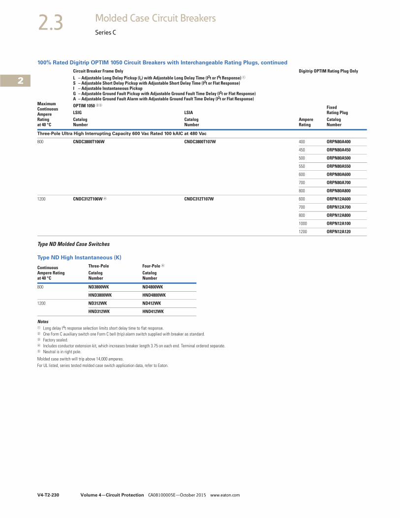
V4-T2-230 Volume 4—Circuit Protection CA08100005E—October 2015 www.eaton.com
2
2
2
2
2
2
2
2
2
2
2
2
2
2
2
2
2
2
2
2
2
2
2
2
2
2
2
2
2
2
2.3 Molded Case Circuit Breakers
Series C
100% Rated Digitrip OPTIM 1050 Circuit Breakers with Interchangeable Rating Plugs, continued
Type ND Molded Case Switches
Type ND High Instantaneous (K)
Notes1 Long delay I4t response selection limits short delay time to flat response.2 One Form C auxiliary switch one Form C bell (trip) alarm switch supplied with breaker as standard.3 Factory sealed.4 Includes conductor extension kit, which increases breaker length 3.75 on each end. Terminal ordered separate.5 Neutral is in right pole.
Molded case switch will trip above 14,000 amperes.For UL listed, series tested molded case switch application data, refer to Eaton.
MaximumContinuousAmpereRatingat 40 °C
Circuit Breaker Frame Only Digitrip OPTIM Rating Plug OnlyL – Adjustable Long Delay Pickup (Ir) with Adjustable Long Delay Time (I2t or I4t Response) 1S – Adjustable Short Delay Pickup with Adjustable Short Delay Time (I2t or Flat Response)I – Adjustable Instantaneous Pickup G – Adjustable Ground Fault Pickup with Adjustable Ground Fault Time Delay (I2t or Flat Response)A – Adjustable Ground Fault Alarm with Adjustable Ground Fault Time Delay (I2t or Flat Response)
Ampere Rating
Fixed Rating Plug
OPTIM 1050 23
LSIG LSIACatalog Number
Catalog Number
Catalog Number
Three-Pole Ultra High Interrupting Capacity 600 Vac Rated 100 kAIC at 480 Vac
800 CNDC3800T106W CNDC3800T107W 400 ORPN80A400
450 ORPN80A450
500 ORPN80A500
550 ORPN80A550
600 ORPN80A600
700 ORPN80A700
800 ORPN80A800
1200 CNDC312T106W 4 CNDC312T107W 600 ORPN12A600
700 ORPN12A700
800 ORPN12A800
1000 ORPN12A100
1200 ORPN12A120
Continuous Ampere Rating at 40 °C
Three-Pole Four-Pole 5
CatalogNumber
CatalogNumber
800 ND3800WK ND4800WK
HND3800WK HND4800WK
1200 ND312WK ND412WK
HND312WK HND412WK
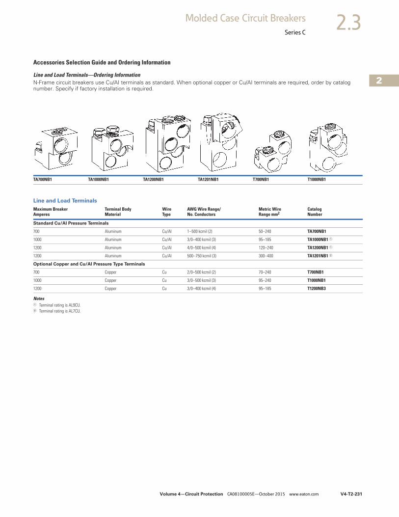
Volume 4—Circuit Protection CA08100005E—October 2015 www.eaton.com V4-T2-231
2
2
2
2
2
2
2
2
2
2
2
2
2
2
2
2
2
2
2
2
2
2
2
2
2
2
2
2
2
2
2.3Molded Case Circuit Breakers
Series C
Accessories Selection Guide and Ordering Information
Line and Load Terminals—Ordering Information N-Frame circuit breakers use Cu/AI terminals as standard. When optional copper or Cu/AI terminals are required, order by catalog number. Specify if factory installation is required.
Line and Load Terminals
Notes1 Terminal rating is AL9CU.2 Terminal rating is AL7CU.
TA700NB1 TA1000NB1 TA1200NB1 TA1201NB1 T700NB1 T1000NB1
Maximum BreakerAmperes
Terminal BodyMaterial
Wire Type
AWG Wire Range/No. Conductors
Metric WireRange mm2
CatalogNumber
Standard Cu/AI Pressure Terminals
700 Aluminum Cu/AI 1–500 kcmil (2) 50–240 TA700NB1
1000 Aluminum Cu/AI 3/0–400 kcmil (3) 95–185 TA1000NB1 1
1200 Aluminum Cu/AI 4/0–500 kcmil (4) 120–240 TA1200NB1 1
1200 Aluminum Cu/AI 500–750 kcmil (3) 300–400 TA1201NB1 2
Optional Copper and Cu/AI Pressure Type Terminals
700 Copper Cu 2/0–500 kcmil (2) 70–240 T700NB1
1000 Copper Cu 3/0–500 kcmil (3) 95–240 T1000NB1
1200 Copper Cu 3/0–400 kcmil (4) 95–185 T1200NB3
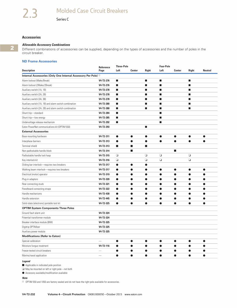
V4-T2-232 Volume 4—Circuit Protection CA08100005E—October 2015 www.eaton.com
2
2
2
2
2
2
2
2
2
2
2
2
2
2
2
2
2
2
2
2
2
2
2
2
2
2
2
2
2
2
2.3 Molded Case Circuit Breakers
Series C
Accessories
Allowable Accessory CombinationsDifferent combinations of accessories can be supplied, depending on the types of accessories and the number of poles in the circuit breaker.
ND Frame Accessories
Legend■ Applicable in indicated pole position❏ May be mounted on left or right pole—not both● Accessory available/modification available
Note1 OPTIM 550 and 1050 are factory sealed and do not have the right pole available for accessories.
DescriptionReference Page
Three-Pole Four-PoleLeft Center Right Left Center Right Neutral
Internal Accessories (Only One Internal Accessory Per Pole) 1
Alarm lockout (Make/Break) V4-T2-276 ■ ■ ■ ■
Alarm lockout (2Make/2Break) V4-T2-276 ■ ■ ■ ■
Auxiliary switch (1A, 1B) V4-T2-278 ■ ■ ■ ■
Auxiliary switch (2A, 2B) V4-T2-278 ■ ■ ■ ■
Auxiliary switch (3A, 3B) V4-T2-278 ■ ■ ■ ■
Auxiliary switch (1A, 1B) and alarm switch combination V4-T2-280 ■ ■ ■ ■
Auxiliary switch (2A, 2B) and alarm switch combination V4-T2-280 ■ ■ ■ ■
Shunt trip—standard V4-T2-284 ■ ■
Shunt trip—low energy V4-T2-285 ■ ■
Undervoltage release mechanism V4-T2-292 ■ ■
Eaton PowerNet communications kit (OPTIM 550) V4-T2-293 ■
External Accessories
Base mounting hardware V4-T2-311 ● ● ● ● ● ● ●
Interphase barriers V4-T2-313 ● ● ● ● ● ● ●
Terminal shield V4-T2-313 ■ ■ ■
Non-padlockable handle block V4-T2-314 ■ ■
Padlockable handle lock hasp V4-T2-315 ❏ ❏ ❏ ❏
Key interlock kit V4-T2-316 ❏ ❏ ❏ ❏
Sliding bar interlock—requires two breakers V4-T2-317 ● ● ●
Walking beam interlock—requires two breakers V4-T2-317 ● ● ● ● ● ● ●
Electrical (motor) operator V4-T2-319 ● ● ● ● ● ● ●
Plug-in adapters V4-T2-320 ● ● ● ● ● ● ●
Rear connecting studs V4-T2-321 ● ● ● ● ● ● ●
Panelboard connecting straps V4-T2-322 ● ● ● ● ● ● ●
Handle mechanisms V4-T2-430 ● ● ● ● ● ● ●
Handle extension V4-T2-445 ● ● ● ● ● ● ●
Solid-state (electronic) portable test kit V4-T2-325 ● ● ● ● ● ● ●
OPTIM System Components Three Poles
Ground fault alarm unit V4-T2-324
Potential transformer module V4-T2-324
Breaker interface module (BIM) V4-T2-325
Digitrip OPTIMizer V4-T2-325
Auxiliary power module V4-T2-325
Modifications (Refer to Eaton)
Special calibration — ● ● ● ● ● ● ●
Moisture fungus treatment V4-T2-116 ● ● ● ● ● ● ●
Freeze-tested circuit breakers — ● ● ● ● ● ● ●
Marine/naval application — ● ● ● ● ● ● ●
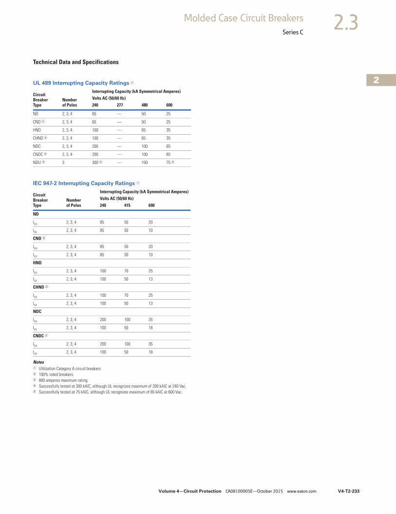
Volume 4—Circuit Protection CA08100005E—October 2015 www.eaton.com V4-T2-233
2
2
2
2
2
2
2
2
2
2
2
2
2
2
2
2
2
2
2
2
2
2
2
2
2
2
2
2
2
2
2.3Molded Case Circuit Breakers
Series C
Technical Data and Specifications
UL 489 Interrupting Capacity Ratings 1
IEC 947-2 Interrupting Capacity Ratings 1
Notes1 Utilization Category A circuit breakers.2 100% rated breakers.3 800 amperes maximum rating.4 Successfully tested at 300 kAIC, although UL recognizes maximum of 200 kAIC at 240 Vac.5 Successfully tested at 75 kAIC, although UL recognizes maximum of 65 kAIC at 600 Vac.
CircuitBreakerType
Numberof Poles
Interrupting Capacity (kA Symmetrical Amperes)Volts AC (50/60 Hz) 240 277 480 600
ND 2, 3, 4 65 — 50 25
CND 2 2, 3, 4 65 — 50 25
HND 2, 3, 4 100 — 65 35
CHND 2 2, 3, 4 100 — 65 35
NDC 2, 3, 4 200 — 100 65
CNDC 2 2, 3, 4 200 — 100 65
NDU 3 3 300 4 — 150 75 5
CircuitBreakerType
Numberof Poles
Interrupting Capacity (kA Symmetrical Amperes)Volts AC (50/60 Hz)240 415 690
ND
Icu 2, 3, 4 85 50 20
Ics 2, 3, 4 85 50 10
CND 2
Icu 2, 3, 4 85 50 20
Ics 2, 3, 4 85 50 10
HND
Icu 2, 3, 4 100 70 25
Ics 2, 3, 4 100 50 13
CHND 2
Icu 2, 3, 4 100 70 25
Ics 2, 3, 4 100 50 13
NDC
Icu 2, 3, 4 200 100 35
Ics 2, 3, 4 100 50 18
CNDC 2
Icu 2, 3, 4 200 100 35
Ics 2, 3, 4 100 50 18
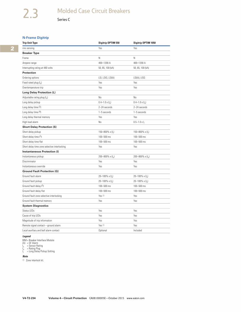
V4-T2-234 Volume 4—Circuit Protection CA08100005E—October 2015 www.eaton.com
2
2
2
2
2
2
2
2
2
2
2
2
2
2
2
2
2
2
2
2
2
2
2
2
2
2
2
2
2
2
2.3 Molded Case Circuit Breakers
Series C
N-Frame Digitrip
LegendBIM = Breaker Interface Module(A) = GF AlarmIs = Sensor RatingIn = Rating PlugIr = Long Delay Pickup Setting
Note1 Zone interlock kit.
Trip Unit Type Digitrip OPTIM 550 Digitrip OPTIM 1050
rms sensing Yes Yes
Breaker Type
Frame N N
Ampere range 400–1200 A 400–1200 A
Interrupting rating at 480 volts 50, 65, 100 (kA) 50, 65, 100 (kA)
Protection
Ordering options LSI, LSIG, LSI(A) LSI(A), LISG
Fixed rated plug (In) Yes Yes
Overtemperature trip Yes Yes
Long Delay Protection (L)
Adjustable rating plug (In) No No
Long delay pickup 0.4–1.0 x (In) 0.4–1.0 x (In)
Long delay time I2t 2–24 seconds 2–24 seconds
Long delay time I4t 1–5 seconds 1–5 seconds
Long delay thermal memory Yes Yes
High load alarm No 0.5–1.0 x Ir
Short Delay Protection (S)
Short delay pickup 150–800% x (Ir) 150–800% x (Ir)
Short delay time I2t 100–500 ms 100–500 ms
Short delay time flat 100–500 ms 100–500 ms
Short delay time zone selective interlocking Yes Yes
Instantaneous Protection (I)
Instantaneous pickup 200–800% x (In) 200–800% x (In)
Discriminator Yes Yes
Instantaneous override Yes Yes
Ground Fault Protection (G)
Ground fault alarm 20–100% x (Is) 20–100% x (Is)
Ground fault pickup 20–100% x (Is) 20–100% x (Is)
Ground fault delay I2t 100–500 ms 100–500 ms
Ground fault delay flat 100–500 ms 100–500 ms
Ground fault zone selective interlocking Yes 1 Yes
Ground fault thermal memory Yes Yes
System Diagnostics
Status LEDs Yes Yes
Cause of trip LEDs Yes Yes
Magnitude of trip information Yes Yes
Remote signal contact—ground alarm Yes 1 Yes
Local auxiliary and bell alarm contact Optional Included
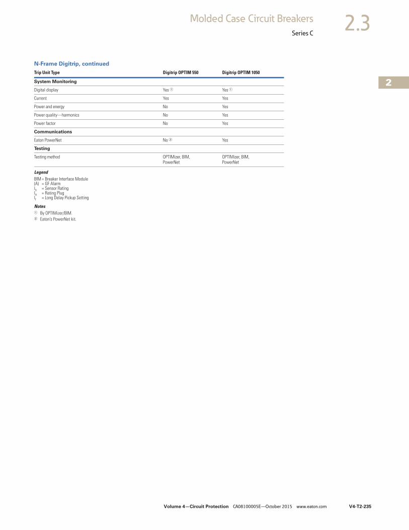
Volume 4—Circuit Protection CA08100005E—October 2015 www.eaton.com V4-T2-235
2
2
2
2
2
2
2
2
2
2
2
2
2
2
2
2
2
2
2
2
2
2
2
2
2
2
2
2
2
2
2.3Molded Case Circuit Breakers
Series C
N-Frame Digitrip, continued
LegendBIM = Breaker Interface Module(A) = GF AlarmIs = Sensor RatingIn = Rating PlugIr = Long Delay Pickup Setting
Notes1 By OPTIMizer/BIM.2 Eaton’s PowerNet kit.
Trip Unit Type Digitrip OPTIM 550 Digitrip OPTIM 1050
System Monitoring
Digital display Yes 1 Yes 1
Current Yes Yes
Power and energy No Yes
Power quality—harmonics No Yes
Power factor No Yes
Communications
Eaton PowerNet No 2 Yes
Testing
Testing method OPTIMizer, BIM, PowerNet
OPTIMizer, BIM, PowerNet
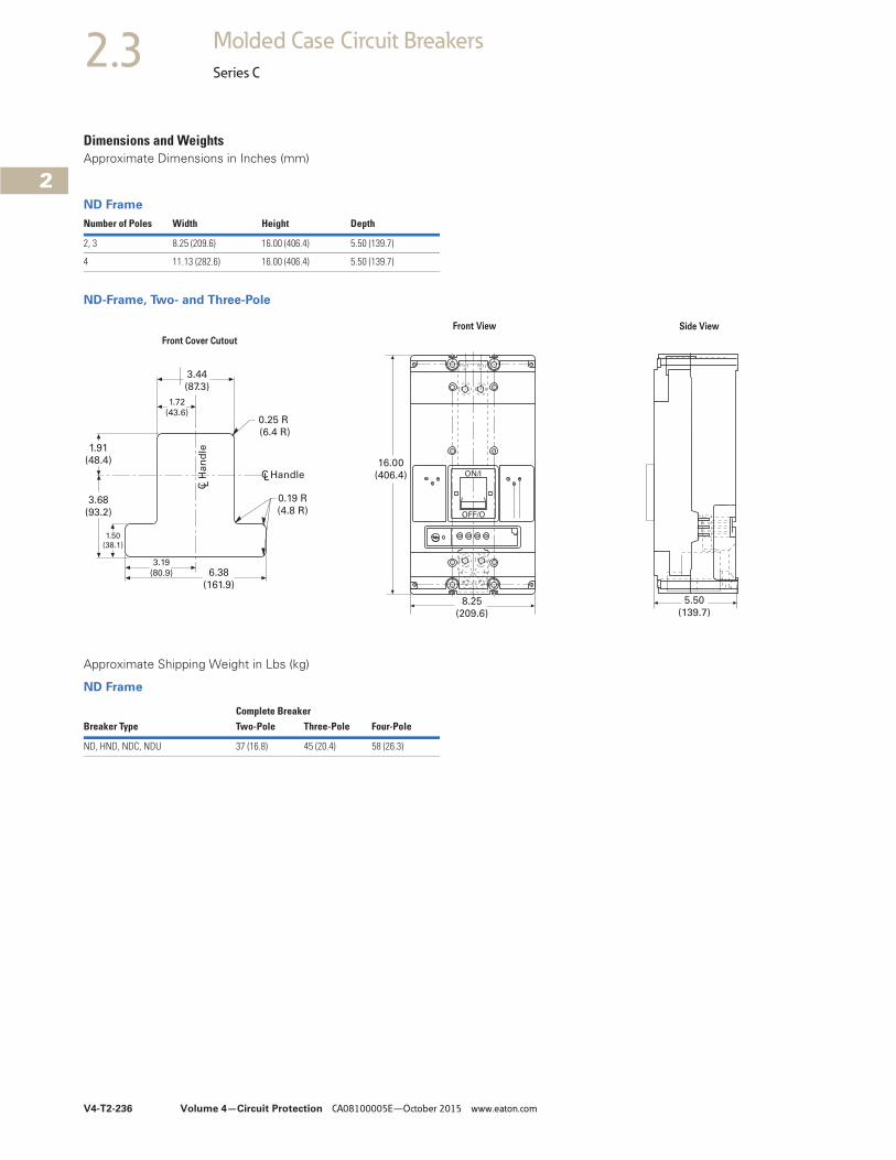
V4-T2-236 Volume 4—Circuit Protection CA08100005E—October 2015 www.eaton.com
2
2
2
2
2
2
2
2
2
2
2
2
2
2
2
2
2
2
2
2
2
2
2
2
2
2
2
2
2
2
2.3 Molded Case Circuit Breakers
Series C
Dimensions and WeightsApproximate Dimensions in Inches (mm)
ND Frame
ND-Frame, Two- and Three-Pole
Approximate Shipping Weight in Lbs (kg)
ND Frame
Number of Poles Width Height Depth
2, 3 8.25 (209.6) 16.00 (406.4) 5.50 (139.7)
4 11.13 (282.6) 16.00 (406.4) 5.50 (139.7)
16.00
(406.4) ON/I
OFF/O
8.25
(209.6)
5.50
(139.7)
3.44
(87.3)
1.72
(43.6)
1.91
(48.4)
3.68
(93.2)
1.50
(38.1)
3.19
(80.9) 6.38
(161.9)
0.19 R
(4.8 R)
0.25 R
(6.4 R)
C LH
an
dle
CLHandle
Front View Side View
Front Cover Cutout
Complete BreakerBreaker Type Two-Pole Three-Pole Four-Pole
ND, HND, NDC, NDU 37 (16.8) 45 (20.4) 58 (26.3)
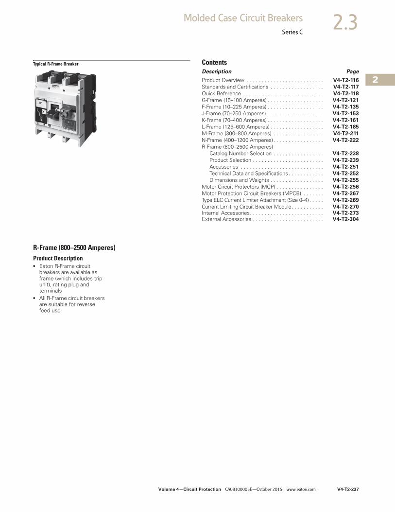
Volume 4—Circuit Protection CA08100005E—October 2015 www.eaton.com V4-T2-237
2
2
2
2
2
2
2
2
2
2
2
2
2
2
2
2
2
2
2
2
2
2
2
2
2
2
2
2
2
2
2.3Molded Case Circuit Breakers
Series C
Typical R-Frame Breaker ContentsDescription Page
Product Overview . . . . . . . . . . . . . . . . . . . . . . . . . . V4-T2-116
Standards and Certifications . . . . . . . . . . . . . . . . . . V4-T2-117
Quick Reference . . . . . . . . . . . . . . . . . . . . . . . . . . . V4-T2-118
G-Frame (15–100 Amperes) . . . . . . . . . . . . . . . . . . . V4-T2-121
F-Frame (10–225 Amperes) . . . . . . . . . . . . . . . . . . . V4-T2-135
J-Frame (70–250 Amperes) . . . . . . . . . . . . . . . . . . . V4-T2-153
K-Frame (70–400 Amperes) . . . . . . . . . . . . . . . . . . . V4-T2-161
L-Frame (125–600 Amperes) . . . . . . . . . . . . . . . . . . V4-T2-185
M-Frame (300–800 Amperes) . . . . . . . . . . . . . . . . . V4-T2-211
N-Frame (400–1200 Amperes) . . . . . . . . . . . . . . . . . V4-T2-222
R-Frame (800–2500 Amperes)Catalog Number Selection . . . . . . . . . . . . . . . . . V4-T2-238
Product Selection . . . . . . . . . . . . . . . . . . . . . . . . V4-T2-239
Accessories . . . . . . . . . . . . . . . . . . . . . . . . . . . . V4-T2-251
Technical Data and Specifications. . . . . . . . . . . . V4-T2-252
Dimensions and Weights . . . . . . . . . . . . . . . . . . V4-T2-255
Motor Circuit Protectors (MCP) . . . . . . . . . . . . . . . . V4-T2-256
Motor Protection Circuit Breakers (MPCB) . . . . . . . V4-T2-267
Type ELC Current Limiter Attachment (Size 0–4) . . . . . V4-T2-269
Current Limiting Circuit Breaker Module. . . . . . . . . . . V4-T2-270Internal Accessories. . . . . . . . . . . . . . . . . . . . . . . . . V4-T2-273External Accessories . . . . . . . . . . . . . . . . . . . . . . . . V4-T2-304
R-Frame (800–2500 Amperes)Product Description● Eaton R-Frame circuit
breakers are available as frame (which includes trip unit), rating plug and terminals
● All R-Frame circuit breakers are suitable for reverse feed use
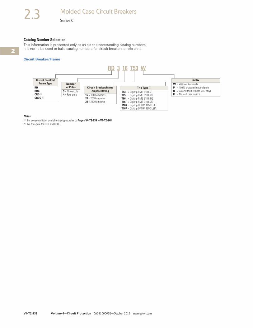
V4-T2-238 Volume 4—Circuit Protection CA08100005E—October 2015 www.eaton.com
2
2
2
2
2
2
2
2
2
2
2
2
2
2
2
2
2
2
2
2
2
2
2
2
2
2
2
2
2
2
2.3 Molded Case Circuit Breakers
Series C
Catalog Number SelectionThis information is presented only as an aid to understanding catalog numbers. It is not to be used to build catalog numbers for circuit breakers or trip units.
Circuit Breaker/Frame
Notes1 For complete list of available trip types, refer to Pages V4-T2-239 to V4-T2-248.2 No four-pole for CRD and CRDC.
Circuit Breaker/Frame Type
RDRDCCRD 2CRDC 2
Number of Poles
3 = Three-pole4 = Four-pole
Circuit Breaker/Frame Ampere Rating
16 = 1600 amperes20 = 2000 amperes25 = 2500 amperes
Trip Type 1
T53 = Digitrip RMS 510 LST65 = Digitrip RMS 610 LSGT86 = Digitrip RMS 810 LSIGT96 = Digitrip RMS 910 LSIGT106 = Digitrip OPTIM 1050 LSIGT107 = Digitrip OPTIM 1050 LSIA
SuffixW = Without terminalsP = 100% protected neutral poleR = Ground fault remote (310 only)K = Molded case switch
RD 3 16 T53 W

Volume 4—Circuit Protection CA08100005E—October 2015 www.eaton.com V4-T2-239
2
2
2
2
2
2
2
2
2
2
2
2
2
2
2
2
2
2
2
2
2
2
2
2
2
2
2
2
2
2
2.3Molded Case Circuit Breakers
Series C
Product Selection
Digitrip RMS 510 Electronic Circuit Breakers with Interchangeable Rating PlugsOrder as individual components: breaker frame (which includes trip unit) and rating plug.
Digitrip RMS 510 Electronic Circuit Breakers with Interchangeable Rating Plugs
MaximumContinuousAmpereRatingat 40 °C
Circuit Breaker Frame Only Digitrip Rating Plug OnlyL – Adjustable Long Delay Pickup (Ir) with Adjustable Long Delay TimeS – Adjustable Short Delay Pickup with Adjustable Short Delay Time (I2t or Flat Response)I – Adjustable Instantaneous Pickup G – Adjustable Ground Fault Pickup with Adjustable Ground Fault Time Delay (I2t or Flat Response)
Rated Current (In)
Fixed Rating PlugLI LS LSI LIG LSG LSIG
Catalog Number Catalog Number
Three-Pole Standard Interrupting Capacity 600 Vac Rated 65 kAIC at 480 Vac
1600 RD316T51W RD316T53W RD316T52W RD316T54W RD316T55W RD316T56W 800 RP6R16A080
1000 RP6R16A100
1200 RP6R16A120
1600 RP6R16A160
2000 RD320T51W RD320T53W RD320T52W RD320T54W RD320T55W RD320T56W 1000 RP6R20A100
1200 RP6R20A120
1600 RP6R20A160
2000 RP6R20A200
2500 RD325T51W RD325T53W RD325T52W RD325T54W RD325T55W RD325T56W 1600 RP6R25A160
2000 RP6R25A200
2500 RP6R25A250
Three-Pole High Interrupting Capacity 600 Vac Rated 100 kAIC at 480 Vac
1600 RDC316T51W RDC316T53W RDC316T52W RDC316T54W RDC316T55W RDC316T56W 800 RP6R16A080
1000 RP6R16A100
1200 RP6R16A120
1600 RP6R16A160
2000 RDC320T51W RDC320T53W RDC320T52W RDC320T54W RDC320T55W RDC320T56W 1000 RP6R20A100
1200 RP6R20A120
1600 RP6R20A160
2000 RP6R20A200
2500 RDC325T51W RDC325T53W RDC325T52W RDC325T54W RDC325T55W RDC325T56W 1600 RP6R25A160
2000 RP6R25A200
2500 RP6R25A250
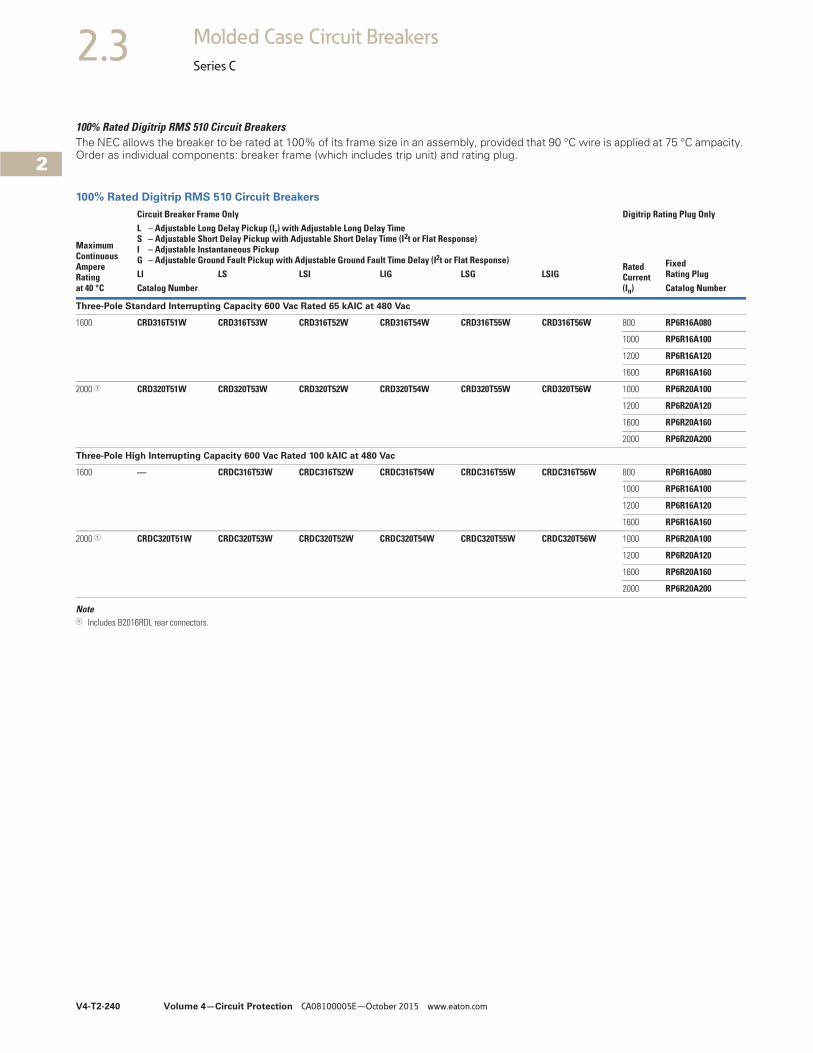
V4-T2-240 Volume 4—Circuit Protection CA08100005E—October 2015 www.eaton.com
2
2
2
2
2
2
2
2
2
2
2
2
2
2
2
2
2
2
2
2
2
2
2
2
2
2
2
2
2
2
2.3 Molded Case Circuit Breakers
Series C
100% Rated Digitrip RMS 510 Circuit BreakersThe NEC allows the breaker to be rated at 100% of its frame size in an assembly, provided that 90 °C wire is applied at 75 °C ampacity. Order as individual components: breaker frame (which includes trip unit) and rating plug.
100% Rated Digitrip RMS 510 Circuit Breakers
Note1 Includes B2016RDL rear connectors.
MaximumContinuousAmpereRatingat 40 °C
Circuit Breaker Frame Only Digitrip Rating Plug OnlyL – Adjustable Long Delay Pickup (Ir) with Adjustable Long Delay TimeS – Adjustable Short Delay Pickup with Adjustable Short Delay Time (I2t or Flat Response)I – Adjustable Instantaneous Pickup G – Adjustable Ground Fault Pickup with Adjustable Ground Fault Time Delay (I2t or Flat Response)
Rated Current (In)
Fixed Rating PlugLI LS LSI LIG LSG LSIG
Catalog Number Catalog Number
Three-Pole Standard Interrupting Capacity 600 Vac Rated 65 kAIC at 480 Vac
1600 CRD316T51W CRD316T53W CRD316T52W CRD316T54W CRD316T55W CRD316T56W 800 RP6R16A080
1000 RP6R16A100
1200 RP6R16A120
1600 RP6R16A160
2000 1 CRD320T51W CRD320T53W CRD320T52W CRD320T54W CRD320T55W CRD320T56W 1000 RP6R20A100
1200 RP6R20A120
1600 RP6R20A160
2000 RP6R20A200
Three-Pole High Interrupting Capacity 600 Vac Rated 100 kAIC at 480 Vac
1600 — CRDC316T53W CRDC316T52W CRDC316T54W CRDC316T55W CRDC316T56W 800 RP6R16A080
1000 RP6R16A100
1200 RP6R16A120
1600 RP6R16A160
2000 1 CRDC320T51W CRDC320T53W CRDC320T52W CRDC320T54W CRDC320T55W CRDC320T56W 1000 RP6R20A100
1200 RP6R20A120
1600 RP6R20A160
2000 RP6R20A200
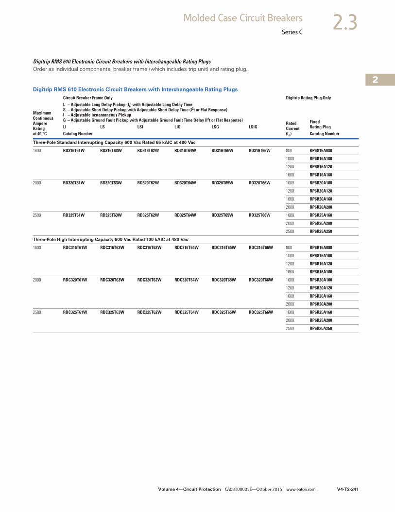
Volume 4—Circuit Protection CA08100005E—October 2015 www.eaton.com V4-T2-241
2
2
2
2
2
2
2
2
2
2
2
2
2
2
2
2
2
2
2
2
2
2
2
2
2
2
2
2
2
2
2.3Molded Case Circuit Breakers
Series C
Digitrip RMS 610 Electronic Circuit Breakers with Interchangeable Rating PlugsOrder as individual components: breaker frame (which includes trip unit) and rating plug.
Digitrip RMS 610 Electronic Circuit Breakers with Interchangeable Rating Plugs
MaximumContinuousAmpereRatingat 40 °C
Circuit Breaker Frame Only Digitrip Rating Plug OnlyL – Adjustable Long Delay Pickup (Ir) with Adjustable Long Delay TimeS – Adjustable Short Delay Pickup with Adjustable Short Delay Time (I2t or Flat Response)I – Adjustable Instantaneous Pickup G – Adjustable Ground Fault Pickup with Adjustable Ground Fault Time Delay (I2t or Flat Response)
Rated Current (In)
Fixed Rating PlugLI LS LSI LIG LSG LSIG
Catalog Number Catalog Number
Three-Pole Standard Interrupting Capacity 600 Vac Rated 65 kAIC at 480 Vac
1600 RD316T61W RD316T63W RD316T62W RD316T64W RD316T65W RD316T66W 800 RP6R16A080
1000 RP6R16A100
1200 RP6R16A120
1600 RP6R16A160
2000 RD320T61W RD320T63W RD320T62W RD320T64W RD320T65W RD320T66W 1000 RP6R20A100
1200 RP6R20A120
1600 RP6R20A160
2000 RP6R20A200
2500 RD325T61W RD325T63W RD325T62W RD325T64W RD325T65W RD325T66W 1600 RP6R25A160
2000 RP6R25A200
2500 RP6R25A250
Three-Pole High Interrupting Capacity 600 Vac Rated 100 kAIC at 480 Vac
1600 RDC316T61W RDC316T63W RDC316T62W RDC316T64W RDC316T65W RDC316T66W 800 RP6R16A080
1000 RP6R16A100
1200 RP6R16A120
1600 RP6R16A160
2000 RDC320T61W RDC320T63W RDC320T62W RDC320T64W RDC320T65W RDC320T66W 1000 RP6R20A100
1200 RP6R20A120
1600 RP6R20A160
2000 RP6R20A200
2500 RDC325T61W RDC325T63W RDC325T62W RDC325T64W RDC325T65W RDC325T66W 1600 RP6R25A160
2000 RP6R25A200
2500 RP6R25A250

V4-T2-242 Volume 4—Circuit Protection CA08100005E—October 2015 www.eaton.com
2
2
2
2
2
2
2
2
2
2
2
2
2
2
2
2
2
2
2
2
2
2
2
2
2
2
2
2
2
2
2.3 Molded Case Circuit Breakers
Series C
100% Rated Digitrip RMS 610 Circuit BreakersThe NEC allows the breaker to be rated at 100% of its frame size in an assembly, provided that 90 °C wire is applied at 75 °C ampacity. Order as individual components: breaker frame (which includes trip unit) and rating plug.
100% Rated Digitrip RMS 610 Circuit Breakers
Note1 Includes B2016RDL rear connectors.
MaximumContinuousAmpereRatingat 40 °C
Circuit Breaker Frame Only Digitrip Rating Plug OnlyL – Adjustable Long Delay Pickup (Ir) with Adjustable Long Delay TimeS – Adjustable Short Delay Pickup with Adjustable Short Delay Time (I2t or Flat Response)I – Adjustable Instantaneous Pickup G – Adjustable Ground Fault Pickup with Adjustable Ground Fault Time Delay (I2t or Flat Response)
Rated Current (In)
Fixed Rating PlugLI LS LSI LIG LSG LSIG
Catalog Number Catalog Number
Three-Pole Standard Interrupting Capacity 600 Vac Rated 65 kAIC at 480 Vac
1600 CRD316T61W CRD316T63W CRD316T62W CRD316T64W CRD316T65W CRD316T66W 800 RP6R16A080
1000 RP6R16A100
1200 RP6R16A120
1600 RP6R16A160
2000 1 CRD320T61W CRD320T63W CRD320T62W CRD320T64W CRD320T65W CRD320T66W 1000 RP6R20A100
1200 RP6R20A120
1600 RP6R20A160
2000 RP6R20A200
Three-Pole High Interrupting Capacity 600 Vac Rated 100 kAIC at 480 Vac
1600 CRDC316T61W CRDC316T63W CRDC316T62W CRDC316T64W CRDC316T65W CRDC316T66W 800 RP6R16A080
1000 RP6R16A100
1200 RP6R16A120
1600 RP6R16A160
2000 1 CRDC320T61W CRDC320T63W CRDC320T62W CRDC320T64W CRDC320T65W CRDC320T66W 1000 RP6R20A100
1200 RP6R20A120
1600 RP6R20A160
2000 RP6R20A200

Volume 4—Circuit Protection CA08100005E—October 2015 www.eaton.com V4-T2-243
2
2
2
2
2
2
2
2
2
2
2
2
2
2
2
2
2
2
2
2
2
2
2
2
2
2
2
2
2
2
2.3Molded Case Circuit Breakers
Series C
Digitrip RMS 810 Electronic Circuit Breakers with Interchangeable Rating PlugsOrder as individual components: breaker frame (which includes trip unit) and rating plug.
Digitrip RMS 810 Electronic Circuit Breakers with Interchangeable Rating Plugs
MaximumContinuousAmpereRatingat 40 °C
Circuit Breaker Frame Only Digitrip Rating Plug OnlyL – Adjustable Long Delay Pickup (Ir) with Adjustable Long Delay TimeS – Adjustable Short Delay Pickup with Adjustable Short Delay Time (I2t or Flat Response)I – Adjustable Instantaneous Pickup G – Adjustable Ground Fault Pickup with Adjustable Ground Fault Time Delay (I2t or Flat Response)
Rated Current(In)
Fixed Rating PlugLI LS LSI LIG LSG LSIG
Catalog Number Catalog Number
Three-Pole Standard Interrupting Capacity 600 Vac Rated 65 kAIC at 480 Vac
1600 RD316T81W RD316T83W RD316T82W RD316T84W RD316T85W RD316T86W 800 RP6R16A080
1000 RP6R16A100
1200 RP6R16A120
1600 RP6R16A160
2000 RD320T81W RD320T83W RD320T82W RD320T84W RD320T85W RD320T86W 1000 RP6R20A100
1200 RP6R20A120
1600 RP6R20A160
2000 RP6R20A200
2500 RD325T81W RD325T83W RD325T82W RD325T84W RD325T85W RD325T86W 1600 RP6R25A160
2000 RP6R25A200
2500 RP6R25A250
Three-Pole High Interrupting Capacity 600 Vac Rated 100 kAIC at 480 Vac
1600 RDC316T81W RDC316T83W RDC316T82W RDC316T84W RDC316T85W RDC316T86W 800 RP6R16A080
1000 RP6R16A100
1200 RP6R16A120
1600 RP6R16A160
2000 RDC320T81W RDC320T83W RDC320T82W RDC320T84W RDC320T85W RDC320T86W 1000 RP6R20A100
1200 RP6R20A120
1600 RP6R20A160
2000 RP6R20A200
2500 RDC325T81W RDC325T83W RDC325T82W RDC325T84W RDC325T85W RDC325T86W 1600 RP6R25A160
2000 RP6R25A200
2500 RP6R25A250
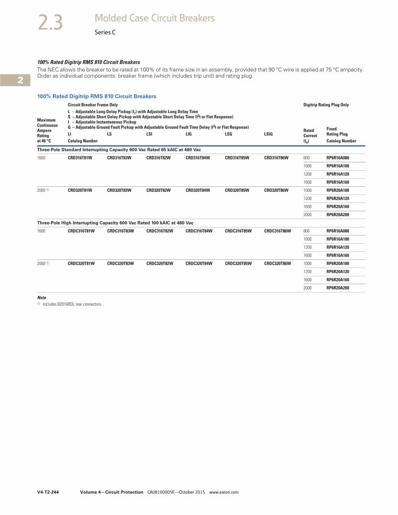
V4-T2-244 Volume 4—Circuit Protection CA08100005E—October 2015 www.eaton.com
2
2
2
2
2
2
2
2
2
2
2
2
2
2
2
2
2
2
2
2
2
2
2
2
2
2
2
2
2
2
2.3 Molded Case Circuit Breakers
Series C
100% Rated Digitrip RMS 810 Circuit BreakersThe NEC allows the breaker to be rated at 100% of its frame size in an assembly, provided that 90 °C wire is applied at 75 °C ampacity. Order as individual components: breaker frame (which includes trip unit) and rating plug.
100% Rated Digitrip RMS 810 Circuit Breakers
Note1 Includes B2016RDL rear connectors.
MaximumContinuousAmpereRatingat 40 °C
Circuit Breaker Frame Only Digitrip Rating Plug OnlyL – Adjustable Long Delay Pickup (Ir) with Adjustable Long Delay TimeS – Adjustable Short Delay Pickup with Adjustable Short Delay Time (I2t or Flat Response)I – Adjustable Instantaneous Pickup G – Adjustable Ground Fault Pickup with Adjustable Ground Fault Time Delay (I2t or Flat Response)
Rated Current(In)
Fixed Rating PlugLI LS LSI LIG LSG LSIG
Catalog Number Catalog Number
Three-Pole Standard Interrupting Capacity 600 Vac Rated 65 kAIC at 480 Vac
1600 CRD316T81W CRD316T83W CRD316T82W CRD316T84W CRD316T85W CRD316T86W 800 RP6R16A080
1000 RP6R16A100
1200 RP6R16A120
1600 RP6R16A160
2000 1 CRD320T81W CRD320T83W CRD320T82W CRD320T84W CRD320T85W CRD320T86W 1000 RP6R20A100
1200 RP6R20A120
1600 RP6R20A160
2000 RP6R20A200
Three-Pole High Interrupting Capacity 600 Vac Rated 100 kAIC at 480 Vac
1600 CRDC316T81W CRDC316T83W CRDC316T82W CRDC316T84W CRDC316T85W CRDC316T86W 800 RP6R16A080
1000 RP6R16A100
1200 RP6R16A120
1600 RP6R16A160
2000 1 CRDC320T81W CRDC320T83W CRDC320T82W CRDC320T84W CRDC320T85W CRDC320T86W 1000 RP6R20A100
1200 RP6R20A120
1600 RP6R20A160
2000 RP6R20A200
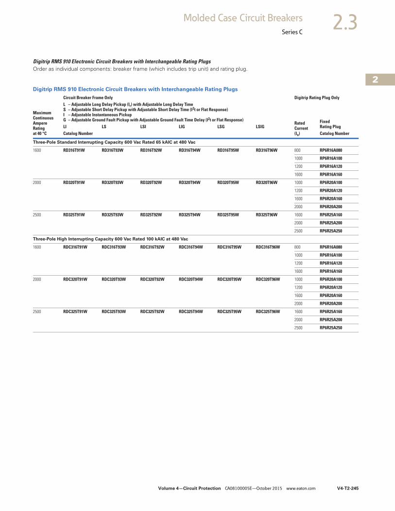
Volume 4—Circuit Protection CA08100005E—October 2015 www.eaton.com V4-T2-245
2
2
2
2
2
2
2
2
2
2
2
2
2
2
2
2
2
2
2
2
2
2
2
2
2
2
2
2
2
2
2.3Molded Case Circuit Breakers
Series C
Digitrip RMS 910 Electronic Circuit Breakers with Interchangeable Rating PlugsOrder as individual components: breaker frame (which includes trip unit) and rating plug.
Digitrip RMS 910 Electronic Circuit Breakers with Interchangeable Rating Plugs
MaximumContinuousAmpereRatingat 40 °C
Circuit Breaker Frame Only Digitrip Rating Plug OnlyL – Adjustable Long Delay Pickup (Ir) with Adjustable Long Delay TimeS – Adjustable Short Delay Pickup with Adjustable Short Delay Time (I2t or Flat Response)I – Adjustable Instantaneous Pickup G – Adjustable Ground Fault Pickup with Adjustable Ground Fault Time Delay (I2t or Flat Response)
Rated Current(In)
Fixed Rating PlugLI LS LSI LIG LSG LSIG
Catalog Number Catalog Number
Three-Pole Standard Interrupting Capacity 600 Vac Rated 65 kAIC at 480 Vac
1600 RD316T91W RD316T93W RD316T92W RD316T94W RD316T95W RD316T96W 800 RP6R16A080
1000 RP6R16A100
1200 RP6R16A120
1600 RP6R16A160
2000 RD320T91W RD320T93W RD320T92W RD320T94W RD320T95W RD320T96W 1000 RP6R20A100
1200 RP6R20A120
1600 RP6R20A160
2000 RP6R20A200
2500 RD325T91W RD325T93W RD325T92W RD325T94W RD325T95W RD325T96W 1600 RP6R25A160
2000 RP6R25A200
2500 RP6R25A250
Three-Pole High Interrupting Capacity 600 Vac Rated 100 kAIC at 480 Vac
1600 RDC316T91W RDC316T93W RDC316T92W RDC316T94W RDC316T95W RDC316T96W 800 RP6R16A080
1000 RP6R16A100
1200 RP6R16A120
1600 RP6R16A160
2000 RDC320T91W RDC320T93W RDC320T92W RDC320T94W RDC320T95W RDC320T96W 1000 RP6R20A100
1200 RP6R20A120
1600 RP6R20A160
2000 RP6R20A200
2500 RDC325T91W RDC325T93W RDC325T92W RDC325T94W RDC325T95W RDC325T96W 1600 RP6R25A160
2000 RP6R25A200
2500 RP6R25A250

V4-T2-246 Volume 4—Circuit Protection CA08100005E—October 2015 www.eaton.com
2
2
2
2
2
2
2
2
2
2
2
2
2
2
2
2
2
2
2
2
2
2
2
2
2
2
2
2
2
2
2.3 Molded Case Circuit Breakers
Series C
100% Rated Digitrip RMS 910 Circuit BreakersThe NEC allows the breaker to be rated at 100% of its frame size in an assembly, provided that 90 °C wire is applied at 75 °C ampacity. Order as individual components: breaker frame (which includes trip unit) and rating plug.
100% Rated Digitrip RMS 910 Circuit Breakers
Note1 Includes B2016RDL rear connectors.
MaximumContinuousAmpereRatingat 40 °C
Circuit Breaker Frame Only Digitrip Rating Plug OnlyL – Adjustable Long Delay Pickup (Ir) with Adjustable Long Delay TimeS – Adjustable Short Delay Pickup with Adjustable Short Delay Time (I2t or Flat Response)I – Adjustable Instantaneous Pickup G – Adjustable Ground Fault Pickup with Adjustable Ground Fault Time Delay (I2t or Flat Response)
Rated Current(In)
Fixed Rating PlugLI LS LSI LIG LSG LSIG
Catalog Number Catalog Number
Three-Pole Standard Interrupting Capacity 600 Vac Rated 65 kAIC at 480 Vac
1600 CRD316T91W CRD316T93W CRD316T92W CRD316T94W CRD316T95W CRD316T96W 800 RP6R16A080
1000 RP6R16A100
1200 RP6R16A120
1600 RP6R16A160
2000 1 CRD320T91W CRD320T93W CRD320T92W CRD320T94W CRD320T95W CRD320T96W 1000 RP6R20A100
1200 RP6R20A120
1600 RP6R20A160
2000 RP6R20A200
Three-Pole High Interrupting Capacity 600 Vac Rated 100 kAIC at 480 Vac
1600 CRDC316T91W CRDC316T93W CRDC316T92W CRDC316T94W CRDC316T95W CRDC316T96W 800 RP6R16A080
1000 RP6R16A100
1000 RP6R16A100
1200 RP6R16A120
2000 1 CRDC320T91W CRDC320T93W CRDC320T92W CRDC320T94W CRDC320T95W CRDC320T96W 1000 RP6R20A100
1200 RP6R20A120
1600 RP6R20A160
2000 RP6R20A200
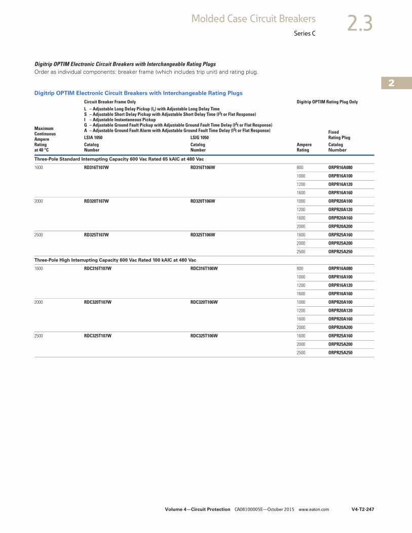
Volume 4—Circuit Protection CA08100005E—October 2015 www.eaton.com V4-T2-247
2
2
2
2
2
2
2
2
2
2
2
2
2
2
2
2
2
2
2
2
2
2
2
2
2
2
2
2
2
2
2.3Molded Case Circuit Breakers
Series C
Digitrip OPTIM Electronic Circuit Breakers with Interchangeable Rating PlugsOrder as individual components: breaker frame (which includes trip unit) and rating plug.
Digitrip OPTIM Electronic Circuit Breakers with Interchangeable Rating Plugs
MaximumContinuousAmpereRatingat 40 °C
Circuit Breaker Frame Only Digitrip OPTIM Rating Plug OnlyL – Adjustable Long Delay Pickup (Ir) with Adjustable Long Delay TimeS – Adjustable Short Delay Pickup with Adjustable Short Delay Time (I2t or Flat Response)I – Adjustable Instantaneous Pickup G – Adjustable Ground Fault Pickup with Adjustable Ground Fault Time Delay (I2t or Flat Response)A – Adjustable Ground Fault Alarm with Adjustable Ground Fault Time Delay (I2t or Flat Response)
Ampere Rating
Fixed Rating PlugLSIA 1050 LSIG 1050
CatalogNumber
CatalogNumber
Catalog Number
Three-Pole Standard Interrupting Capacity 600 Vac Rated 65 kAIC at 480 Vac
1600 RD316T107W RD316T106W 800 ORPR16A080
1000 ORPR16A100
1200 ORPR16A120
1600 ORPR16A160
2000 RD320T107W RD320T106W 1000 ORPR20A100
1200 ORPR20A120
1600 ORPR20A160
2000 ORPR20A200
2500 RD325T107W RD325T106W 1600 ORPR25A160
2000 ORPR25A200
2500 ORPR25A250
Three-Pole High Interrupting Capacity 600 Vac Rated 100 kAIC at 480 Vac
1600 RDC316T107W RDC316T106W 800 ORPR16A080
1000 ORPR16A100
1200 ORPR16A120
1600 ORPR16A160
2000 RDC320T107W RDC320T106W 1000 ORPR20A100
1200 ORPR20A120
1600 ORPR20A160
2000 ORPR20A200
2500 RDC325T107W RDC325T106W 1600 ORPR25A160
2000 ORPR25A200
2500 ORPR25A250
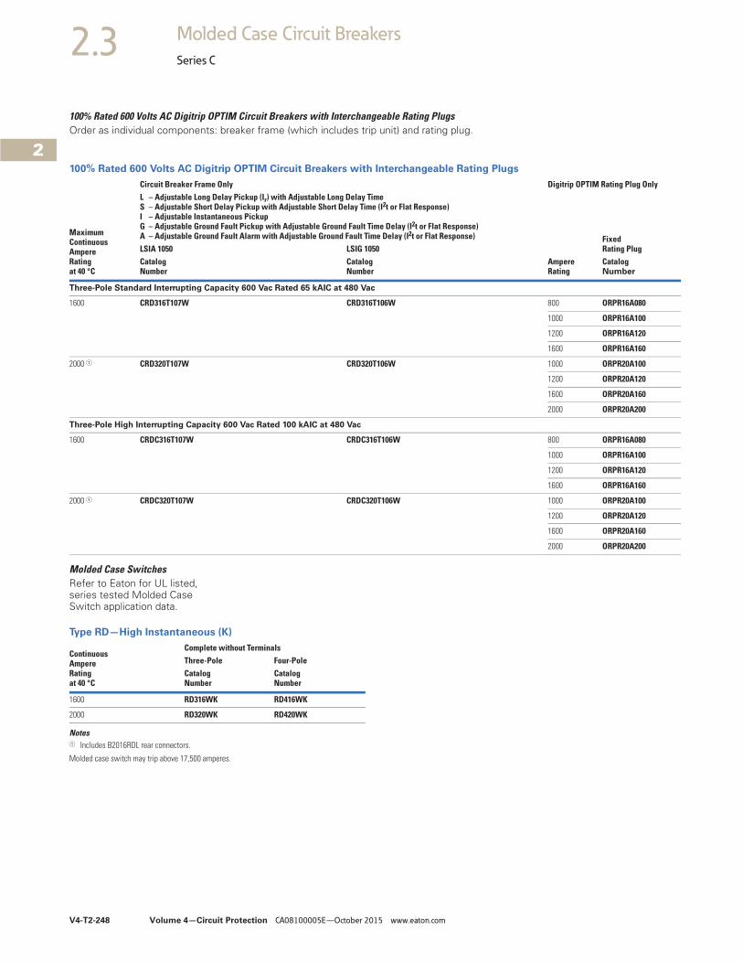
V4-T2-248 Volume 4—Circuit Protection CA08100005E—October 2015 www.eaton.com
2
2
2
2
2
2
2
2
2
2
2
2
2
2
2
2
2
2
2
2
2
2
2
2
2
2
2
2
2
2
2.3 Molded Case Circuit Breakers
Series C
100% Rated 600 Volts AC Digitrip OPTIM Circuit Breakers with Interchangeable Rating PlugsOrder as individual components: breaker frame (which includes trip unit) and rating plug.
100% Rated 600 Volts AC Digitrip OPTIM Circuit Breakers with Interchangeable Rating Plugs
Molded Case SwitchesRefer to Eaton for UL listed, series tested Molded Case Switch application data.
Type RD—High Instantaneous (K)
Notes1 Includes B2016RDL rear connectors.
Molded case switch may trip above 17,500 amperes.
MaximumContinuousAmpereRatingat 40 °C
Circuit Breaker Frame Only Digitrip OPTIM Rating Plug OnlyL – Adjustable Long Delay Pickup (Ir) with Adjustable Long Delay TimeS – Adjustable Short Delay Pickup with Adjustable Short Delay Time (I2t or Flat Response)I – Adjustable Instantaneous Pickup G – Adjustable Ground Fault Pickup with Adjustable Ground Fault Time Delay (I2t or Flat Response)A – Adjustable Ground Fault Alarm with Adjustable Ground Fault Time Delay (I2t or Flat Response)
Ampere Rating
Fixed Rating PlugLSIA 1050 LSIG 1050
CatalogNumber
CatalogNumber
Catalog Number
Three-Pole Standard Interrupting Capacity 600 Vac Rated 65 kAIC at 480 Vac
1600 CRD316T107W CRD316T106W 800 ORPR16A080
1000 ORPR16A100
1200 ORPR16A120
1600 ORPR16A160
2000 1 CRD320T107W CRD320T106W 1000 ORPR20A100
1200 ORPR20A120
1600 ORPR20A160
2000 ORPR20A200
Three-Pole High Interrupting Capacity 600 Vac Rated 100 kAIC at 480 Vac
1600 CRDC316T107W CRDC316T106W 800 ORPR16A080
1000 ORPR16A100
1200 ORPR16A120
1600 ORPR16A160
2000 1 CRDC320T107W CRDC320T106W 1000 ORPR20A100
1200 ORPR20A120
1600 ORPR20A160
2000 ORPR20A200
ContinuousAmpereRating at 40 °C
Complete without TerminalsThree-Pole Four-PoleCatalogNumber
CatalogNumber
1600 RD316WK RD416WK
2000 RD320WK RD420WK
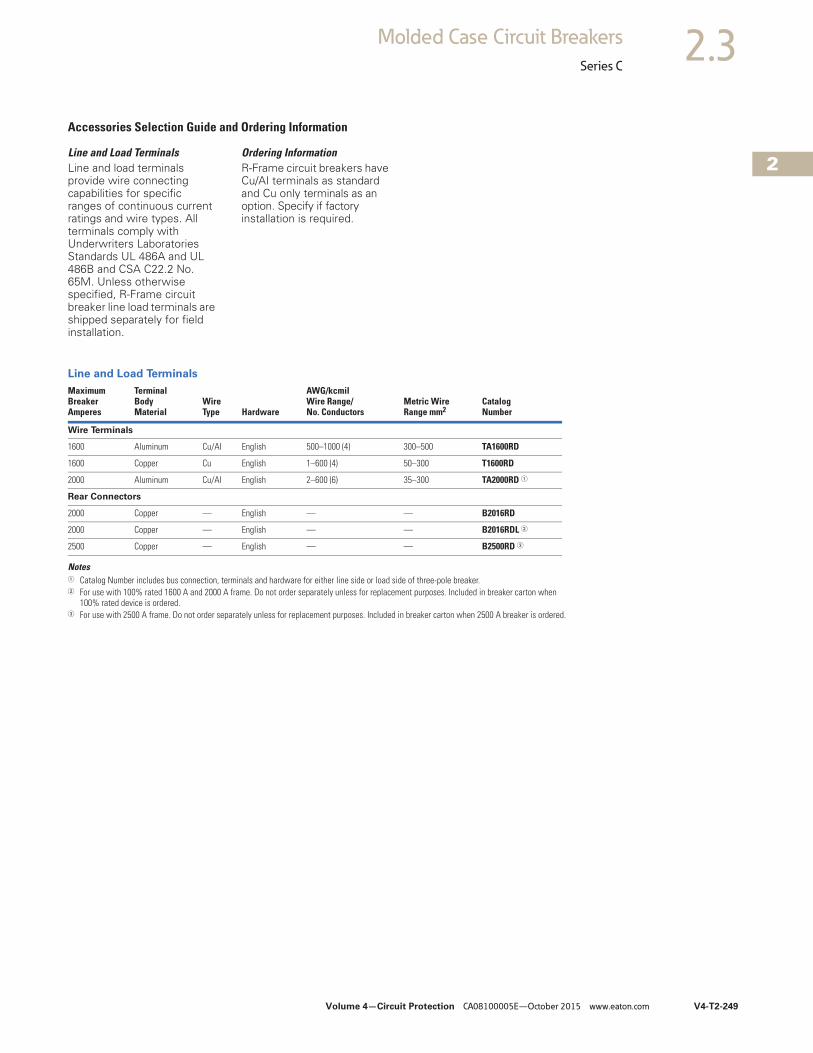
Volume 4—Circuit Protection CA08100005E—October 2015 www.eaton.com V4-T2-249
2
2
2
2
2
2
2
2
2
2
2
2
2
2
2
2
2
2
2
2
2
2
2
2
2
2
2
2
2
2
2.3Molded Case Circuit Breakers
Series C
Accessories Selection Guide and Ordering Information
Line and Load TerminalsLine and load terminals provide wire connecting capabilities for specific ranges of continuous current ratings and wire types. All terminals comply with Underwriters Laboratories Standards UL 486A and UL 486B and CSA C22.2 No. 65M. Unless otherwise specified, R-Frame circuit breaker line load terminals are shipped separately for field installation.
Ordering InformationR-Frame circuit breakers have Cu/AI terminals as standard and Cu only terminals as an option. Specify if factory installation is required.
Line and Load Terminals
Notes1 Catalog Number includes bus connection, terminals and hardware for either line side or load side of three-pole breaker.2 For use with 100% rated 1600 A and 2000 A frame. Do not order separately unless for replacement purposes. Included in breaker carton when
100% rated device is ordered.3 For use with 2500 A frame. Do not order separately unless for replacement purposes. Included in breaker carton when 2500 A breaker is ordered.
MaximumBreakerAmperes
TerminalBodyMaterial
WireType Hardware
AWG/kcmilWire Range/No. Conductors
Metric WireRange mm2
CatalogNumber
Wire Terminals
1600 Aluminum Cu/AI English 500–1000 (4) 300–500 TA1600RD
1600 Copper Cu English 1–600 (4) 50–300 T1600RD
2000 Aluminum Cu/AI English 2–600 (6) 35–300 TA2000RD 1
Rear Connectors
2000 Copper — English — — B2016RD
2000 Copper — English — — B2016RDL 2
2500 Copper — English — — B2500RD 3
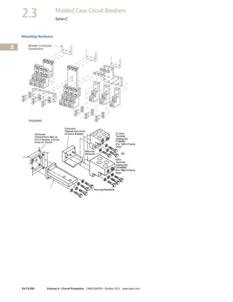
V4-T2-250 Volume 4—Circuit Protection CA08100005E—October 2015 www.eaton.com
2
2
2
2
2
2
2
2
2
2
2
2
2
2
2
2
2
2
2
2
2
2
2
2
2
2
2
2
2
2
2.3 Molded Case Circuit Breakers
Series C
Mounting Hardware
Breaker Line/LoadConductors
TA2000RD
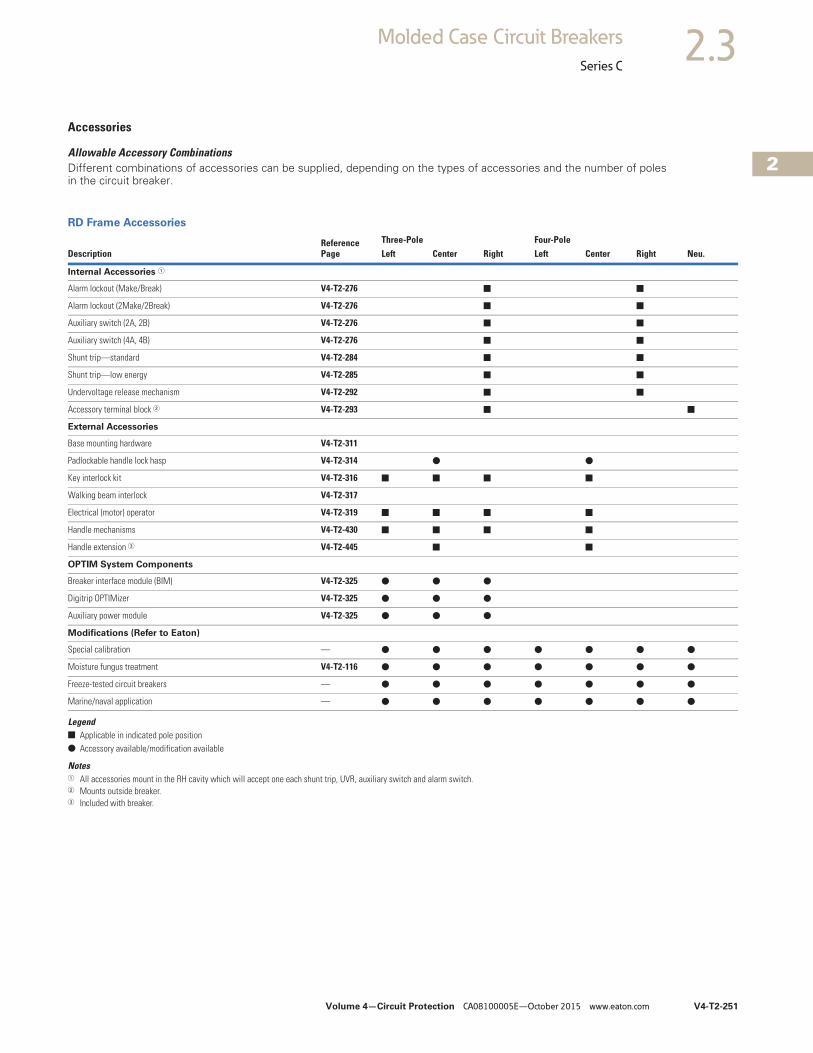
Volume 4—Circuit Protection CA08100005E—October 2015 www.eaton.com V4-T2-251
2
2
2
2
2
2
2
2
2
2
2
2
2
2
2
2
2
2
2
2
2
2
2
2
2
2
2
2
2
2
2.3Molded Case Circuit Breakers
Series C
Accessories
Allowable Accessory CombinationsDifferent combinations of accessories can be supplied, depending on the types of accessories and the number of poles in the circuit breaker.
RD Frame Accessories
Legend■ Applicable in indicated pole position● Accessory available/modification available
Notes1 All accessories mount in the RH cavity which will accept one each shunt trip, UVR, auxiliary switch and alarm switch.2 Mounts outside breaker.3 Included with breaker.
DescriptionReference Page
Three-Pole Four-PoleLeft Center Right Left Center Right Neu.
Internal Accessories 1
Alarm lockout (Make/Break) V4-T2-276 ■ ■
Alarm lockout (2Make/2Break) V4-T2-276 ■ ■
Auxiliary switch (2A, 2B) V4-T2-276 ■ ■
Auxiliary switch (4A, 4B) V4-T2-276 ■ ■
Shunt trip—standard V4-T2-284 ■ ■
Shunt trip—low energy V4-T2-285 ■ ■
Undervoltage release mechanism V4-T2-292 ■ ■
Accessory terminal block 2 V4-T2-293 ■ ■
External Accessories
Base mounting hardware V4-T2-311
Padlockable handle lock hasp V4-T2-314 ● ●
Key interlock kit V4-T2-316 ■ ■ ■ ■
Walking beam interlock V4-T2-317
Electrical (motor) operator V4-T2-319 ■ ■ ■ ■
Handle mechanisms V4-T2-430 ■ ■ ■ ■
Handle extension 3 V4-T2-445 ■ ■
OPTIM System Components
Breaker interface module (BIM) V4-T2-325 ● ● ●
Digitrip OPTIMizer V4-T2-325 ● ● ●
Auxiliary power module V4-T2-325 ● ● ●
Modifications (Refer to Eaton)
Special calibration — ● ● ● ● ● ● ●
Moisture fungus treatment V4-T2-116 ● ● ● ● ● ● ●
Freeze-tested circuit breakers — ● ● ● ● ● ● ●
Marine/naval application — ● ● ● ● ● ● ●
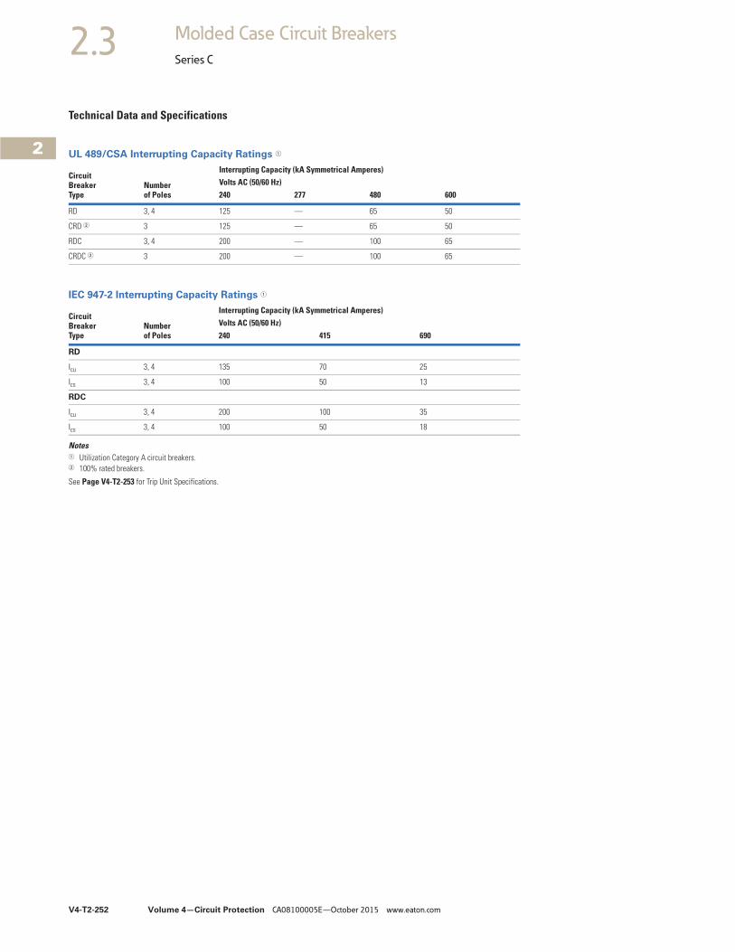
V4-T2-252 Volume 4—Circuit Protection CA08100005E—October 2015 www.eaton.com
2
2
2
2
2
2
2
2
2
2
2
2
2
2
2
2
2
2
2
2
2
2
2
2
2
2
2
2
2
2
2.3 Molded Case Circuit Breakers
Series C
Technical Data and Specifications
UL 489/CSA Interrupting Capacity Ratings 1
IEC 947-2 Interrupting Capacity Ratings 1
Notes1 Utilization Category A circuit breakers.2 100% rated breakers.
See Page V4-T2-253 for Trip Unit Specifications.
CircuitBreakerType
Numberof Poles
Interrupting Capacity (kA Symmetrical Amperes)Volts AC (50/60 Hz) 240 277 480 600
RD 3, 4 125 — 65 50
CRD 2 3 125 — 65 50
RDC 3, 4 200 — 100 65
CRDC 2 3 200 — 100 65
CircuitBreakerType
Numberof Poles
Interrupting Capacity (kA Symmetrical Amperes)Volts AC (50/60 Hz) 240 415 690
RD
Icu 3, 4 135 70 25
Ics 3, 4 100 50 13
RDC
Icu 3, 4 200 100 35
Ics 3, 4 100 50 18
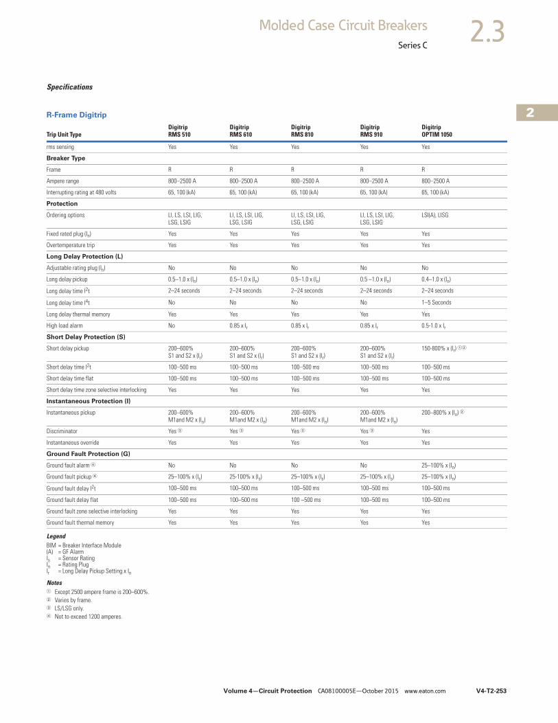
Volume 4—Circuit Protection CA08100005E—October 2015 www.eaton.com V4-T2-253
2
2
2
2
2
2
2
2
2
2
2
2
2
2
2
2
2
2
2
2
2
2
2
2
2
2
2
2
2
2
2.3Molded Case Circuit Breakers
Series C
Specifications
R-Frame Digitrip
LegendBIM = Breaker Interface Module(A) = GF AlarmIs = Sensor RatingIn = Rating PlugIr = Long Delay Pickup Setting x In
Notes1 Except 2500 ampere frame is 200–600%.2 Varies by frame.3 LS/LSG only.4 Not to exceed 1200 amperes.
Trip Unit TypeDigitrip RMS 510
Digitrip RMS 610
Digitrip RMS 810
Digitrip RMS 910
Digitrip OPTIM 1050
rms sensing Yes Yes Yes Yes Yes
Breaker Type
Frame R R R R R
Ampere range 800–2500 A 800–2500 A 800–2500 A 800–2500 A 800–2500 A
Interrupting rating at 480 volts 65, 100 (kA) 65, 100 (kA) 65, 100 (kA) 65, 100 (kA) 65, 100 (kA)
Protection
Ordering options LI, LS, LSI, LIG,LSG, LSIG
LI, LS, LSI, LIG,LSG, LSIG
LI, LS, LSI, LIG,LSG, LSIG
LI, LS, LSI, LIG,LSG, LSIG
LSI(A), LISG
Fixed rated plug (In) Yes Yes Yes Yes Yes
Overtemperature trip Yes Yes Yes Yes Yes
Long Delay Protection (L)
Adjustable rating plug (In) No No No No No
Long delay pickup 0.5–1.0 x (In) 0.5–1.0 x (In) 0.5–1.0 x (In) 0.5 –1.0 x (In) 0.4–1.0 x (In)
Long delay time I2t 2–24 seconds 2–24 seconds 2–24 seconds 2–24 seconds 2–24 seconds
Long delay time I4t No No No No 1–5 Seconds
Long delay thermal memory Yes Yes Yes Yes Yes
High load alarm No 0.85 x Ir 0.85 x Ir 0.85 x Ir 0.5-1.0 x Ir
Short Delay Protection (S)
Short delay pickup 200–600% S1 and S2 x (Ir)
200–600% S1 and S2 x (Ir)
200–600% S1 and S2 x (Ir)
200–600% S1 and S2 x (Ir)
150-800% x (Ir) 12
Short delay time I2t 100–500 ms 100–500 ms 100–500 ms 100–500 ms 100–500 ms
Short delay time flat 100–500 ms 100–500 ms 100–500 ms 100–500 ms 100–500 ms
Short delay time zone selective interlocking Yes Yes Yes Yes Yes
Instantaneous Protection (I)
Instantaneous pickup 200–600%M1and M2 x (In)
200–600%M1and M2 x (In)
200–600%M1and M2 x (In)
200–600%M1and M2 x (In)
200–800% x (In) 2
Discriminator Yes 3 Yes 3 Yes 3 Yes 3 Yes
Instantaneous override Yes Yes Yes Yes Yes
Ground Fault Protection (G)
Ground fault alarm 4 No No No No 25–100% x (In)
Ground fault pickup 4 25–100% x (Is) 25-100% x (Is) 25–100% x (Is) 25–100% x (Is) 25–100% x (In)
Ground fault delay I2t 100–500 ms 100–500 ms 100–500 ms 100–500 ms 100–500 ms
Ground fault delay flat 100–500 ms 100–500 ms 100 –500 ms 100–500 ms 100–500 ms
Ground fault zone selective interlocking Yes Yes Yes Yes Yes
Ground fault thermal memory Yes Yes Yes Yes Yes
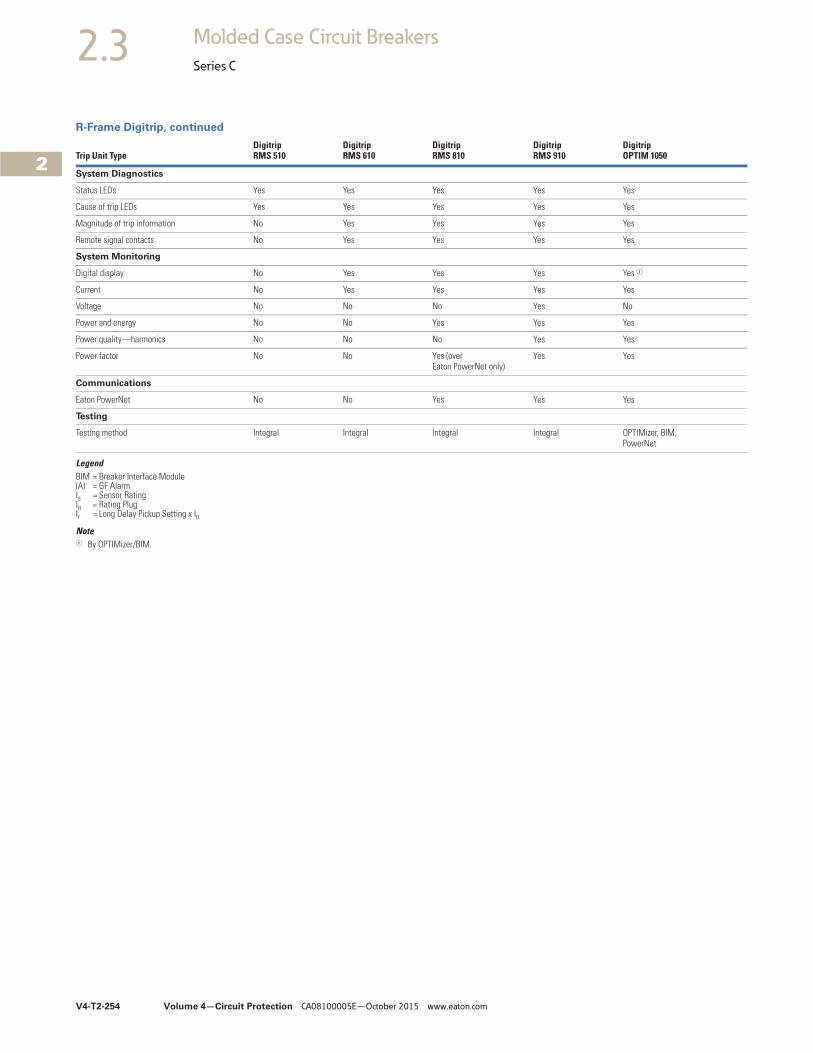
V4-T2-254 Volume 4—Circuit Protection CA08100005E—October 2015 www.eaton.com
2
2
2
2
2
2
2
2
2
2
2
2
2
2
2
2
2
2
2
2
2
2
2
2
2
2
2
2
2
2
2.3 Molded Case Circuit Breakers
Series C
R-Frame Digitrip, continued
LegendBIM = Breaker Interface Module(A) = GF AlarmIs = Sensor RatingIn = Rating PlugIr = Long Delay Pickup Setting x In
Note1 By OPTIMizer/BIM.
Trip Unit TypeDigitrip RMS 510
Digitrip RMS 610
Digitrip RMS 810
Digitrip RMS 910
Digitrip OPTIM 1050
System Diagnostics
Status LEDs Yes Yes Yes Yes Yes
Cause of trip LEDs Yes Yes Yes Yes Yes
Magnitude of trip information No Yes Yes Yes Yes
Remote signal contacts No Yes Yes Yes Yes
System Monitoring
Digital display No Yes Yes Yes Yes 1
Current No Yes Yes Yes Yes
Voltage No No No Yes No
Power and energy No No Yes Yes Yes
Power quality—harmonics No No No Yes Yes
Power factor No No Yes (over Eaton PowerNet only)
Yes Yes
Communications
Eaton PowerNet No No Yes Yes Yes
Testing
Testing method Integral Integral Integral Integral OPTIMizer, BIM, PowerNet
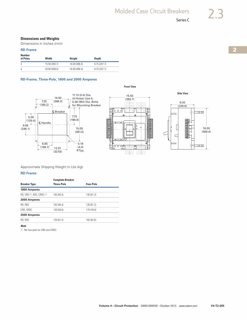
Volume 4—Circuit Protection CA08100005E—October 2015 www.eaton.com V4-T2-255
2
2
2
2
2
2
2
2
2
2
2
2
2
2
2
2
2
2
2
2
2
2
2
2
2
2
2
2
2
2
2.3Molded Case Circuit Breakers
Series C
Dimensions and WeightsDimensions in Inches (mm)
RD Frame
RD-Frame, Three-Pole, 1600 and 2000 Amperes
Approximate Shipping Weight in Lbs (kg)
RD Frame
Note1 No four-pole for CRD and CRDC.
Numberof Poles Width Height Depth
3 15.50 (393.7) 16.00 (406.4) 9.75 (247.7)
4 20.00 (508.0) 16.00 (406.4) 9.75 (247.7)
PushToTrip
9.69
(246.1)
5.09
(129.4)
7.25
(184.2)
14.50
(368.3)
CL Breaker
HandleCL
11.13 (0.4) Dia.
(4 Holes) Use 4,
0.38 (Mil) Dia. Bolts
for Mounting Breaker
7.75
(196.9)
15.00
(381.0)
0.16
(4.0)
R Typ.
6.65
(166.7) 12.91
(327.8)
Front View
Side View15.50
(393.7)
9.00
(228.6)
16.00
(406.4)
Complete BreakerBreaker Type Three-Pole Four-Pole
1600 Amperes
RD, CRD 1, RDC, CRDC 1 102 (46.3) 135 (61.2)
2000 Amperes
RD, RDC 102 (46.3) 135 (61.2)
CRD, CRDC 130 (59.0) 175 (79.4)
2500 Amperes
RD, RDC 135 (61.2) 182 (82.6)
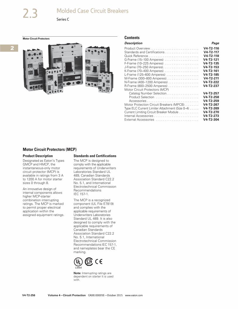
V4-T2-256 Volume 4—Circuit Protection CA08100005E—October 2015 www.eaton.com
2
2
2
2
2
2
2
2
2
2
2
2
2
2
2
2
2
2
2
2
2
2
2
2
2
2
2
2
2
2
2.3 Molded Case Circuit Breakers
Series C
Motor Circuit Protectors ContentsDescription Page
Product Overview . . . . . . . . . . . . . . . . . . . . . . . . . . . V4-T2-116Standards and Certifications. . . . . . . . . . . . . . . . . . . V4-T2-117Quick Reference . . . . . . . . . . . . . . . . . . . . . . . . . . . . V4-T2-118G-Frame (15–100 Amperes) . . . . . . . . . . . . . . . . . . . V4-T2-121F-Frame (10–225 Amperes) . . . . . . . . . . . . . . . . . . . V4-T2-135J-Frame (70–250 Amperes). . . . . . . . . . . . . . . . . . . . V4-T2-153K-Frame (70–400 Amperes) . . . . . . . . . . . . . . . . . . . V4-T2-161L-Frame (125–600 Amperes) . . . . . . . . . . . . . . . . . . V4-T2-185M-Frame (300–800 Amperes). . . . . . . . . . . . . . . . . . V4-T2-211N-Frame (400–1200 Amperes) . . . . . . . . . . . . . . . . . V4-T2-222R-Frame (800–2500 Amperes) . . . . . . . . . . . . . . . . . V4-T2-237Motor Circuit Protectors (MCP)
Catalog Number Selection. . . . . . . . . . . . . . . . . . V4-T2-257Product Selection . . . . . . . . . . . . . . . . . . . . . . . . V4-T2-258Accessories . . . . . . . . . . . . . . . . . . . . . . . . . . . . . V4-T2-259
Motor Protection Circuit Breakers (MPCB) . . . . . . . . V4-T2-267Type ELC Current Limiter Attachment (Size 0–4) . . . . . V4-T2-269Current Limiting Circuit Breaker Module . . . . . . . . . . . V4-T2-270Internal Accessories . . . . . . . . . . . . . . . . . . . . . . . . . V4-T2-273External Accessories . . . . . . . . . . . . . . . . . . . . . . . . V4-T2-304
Motor Circuit Protectors (MCP)Product DescriptionDesignated as Eaton’s Types GMCP and HMCP, the instantaneous-only motor circuit protector (MCP) is available in ratings from 3 A to 1200 A for motor starter sizes 0 through 8.
An innovative design of internal components allows higher MCP-starter combination interrupting ratings. The MCP is marked to permit proper electrical application within the assigned equipment ratings.
Standards and CertificationsThe MCP is designed to comply with the applicable requirements of Underwriters Laboratories Standard UL 489, Canadian Standards Association Standard C22.2 No. 5.1, and International Electrotechnical Commission Recommendations IEC 157-1.
The MCP is a recognized component (UL File E7819) and complies with the applicable requirements of Underwriters Laboratories Standard UL 489. It is also designed to comply with the applicable requirements of Canadian Standards Association Standard C22.2 No. 5.1, International Electrotechnical Commission Recommendations IEC 157-1, and nameplates bear the CE marking.
Note: Interrupting ratings are dependent on starter it is used with.
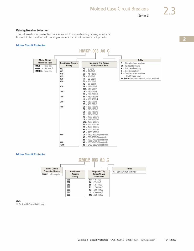
Volume 4—Circuit Protection CA08100005E—October 2015 www.eaton.com V4-T2-257
2
2
2
2
2
2
2
2
2
2
2
2
2
2
2
2
2
2
2
2
2
2
2
2
2
2
2
2
2
2
2.3Molded Case Circuit Breakers
Series C
Catalog Number SelectionThis information is presented only as an aid to understanding catalog numbers. It is not to be used to build catalog numbers for circuit breakers or trip units.
Motor Circuit Protector
Motor Circuit Protector
Note1 On J- and K-Frame HMCPs only.
HMCP 003 A0 C
Motor Circuit Protective Type
HMCP = Three-poleHM2P = Two-pole 1HMCPS = Three-pole
SuffixC = Non-aluminum terminalsW = Without terminalsX = Load terminals onlyY = Line terminals onlyS = Stainless steel terminals
(150A frame only)No Suffix: Standard terminals on line and load
Magnetic Trip Range/NEMA Starter Size
A0 = 9–30/0C0 = 21–70/0E0 = 45–150/0D0 = 40–60/0H1 = 90–300/1G2 = 80–120/2K2 = 50–500/2J2 = 115–170/2M2 = 210–700/2L3 = 160–240/3R3 = 300–1000/3T4 = 450–1500/4U4 = 750–2500/4A5 = 350–700/5C5 = 450–900/5D5 = 500–1000/5F5 = 625–1250/5G5 = 750–1500/5J5 = 875–1750/5K5 = 1000–2000/5L5 = 1125–2250/5W5 = 1250–2500/5N5 = 1500–3000/5R5 = 1750–3500/5X5 = 2000–4000/5Y5 = 2250–4500/5L6 = 1800–6000/6 (electronic)X6 = 500–2500/6 (electronic)Y6 = 1000–4000/6 (electronic)X7 = 1600–6400/7 (electronic)Y8 = 2400–9600/8 (electronic)
Continuous Ampere Rating
003007015025030050
070
100
150
250
400
600
8001200
Motor Circuit Protective Device
GMCP = Three-pole
SuffixC = Non-aluminum terminalsContinuous
Ampere Rating
003007015030050060063
Magnetic Trip Range/NEMA Starter Size
A0 = 15–30/0C0 = 35–70/0E0 = 75–150/0H1 = 150–300/1K2 = 250–500/2J2 = 300–600/2M2 = 320–630/2
GMCP 003 A0 C
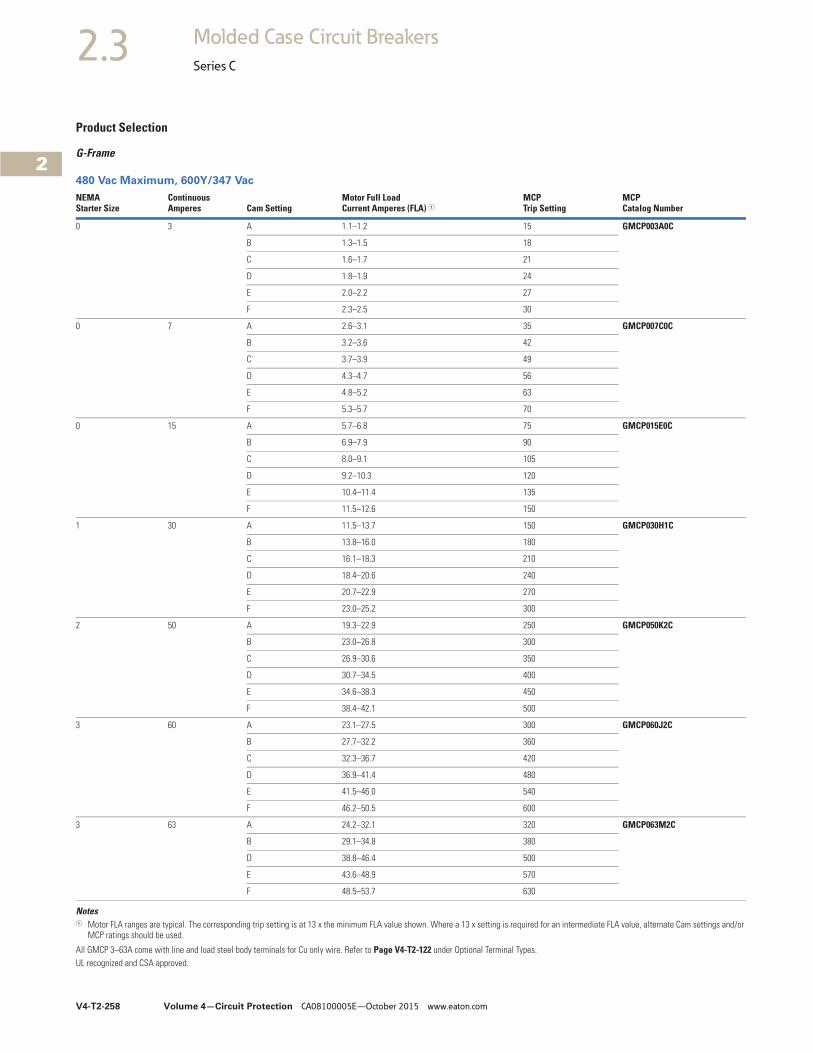
V4-T2-258 Volume 4—Circuit Protection CA08100005E—October 2015 www.eaton.com
2
2
2
2
2
2
2
2
2
2
2
2
2
2
2
2
2
2
2
2
2
2
2
2
2
2
2
2
2
2
2.3 Molded Case Circuit Breakers
Series C
Product Selection
G-Frame
480 Vac Maximum, 600Y/347 Vac
Notes1 Motor FLA ranges are typical. The corresponding trip setting is at 13 x the minimum FLA value shown. Where a 13 x setting is required for an intermediate FLA value, alternate Cam settings and/or
MCP ratings should be used.
All GMCP 3–63A come with line and load steel body terminals for Cu only wire. Refer to Page V4-T2-122 under Optional Terminal Types.UL recognized and CSA approved.
NEMAStarter Size
ContinuousAmperes Cam Setting
Motor Full LoadCurrent Amperes (FLA) 1
MCPTrip Setting
MCPCatalog Number
0 3 A 1.1–1.2 15 GMCP003A0C
B 1.3–1.5 18
C 1.6–1.7 21
D 1.8–1.9 24
E 2.0–2.2 27
F 2.3–2.5 30
0 7 A 2.6–3.1 35 GMCP007C0C
B 3.2–3.6 42
C 3.7–3.9 49
D 4.3–4.7 56
E 4.8–5.2 63
F 5.3–5.7 70
0 15 A 5.7–6.8 75 GMCP015E0C
B 6.9–7.9 90
C 8.0–9.1 105
D 9.2–10.3 120
E 10.4–11.4 135
F 11.5–12.6 150
1 30 A 11.5–13.7 150 GMCP030H1C
B 13.8–16.0 180
C 16.1–18.3 210
D 18.4–20.6 240
E 20.7–22.9 270
F 23.0–25.2 300
2 50 A 19.3–22.9 250 GMCP050K2C
B 23.0–26.8 300
C 26.9–30.6 350
D 30.7–34.5 400
E 34.6–38.3 450
F 38.4–42.1 500
3 60 A 23.1–27.5 300 GMCP060J2C
B 27.7–32.2 360
C 32.3–36.7 420
D 36.9–41.4 480
E 41.5–46.0 540
F 46.2–50.5 600
3 63 A 24.2–32.1 320 GMCP063M2C
B 29.1–34.8 380
D 38.8–46.4 500
E 43.6–48.9 570
F 48.5–53.7 630

Volume 4—Circuit Protection CA08100005E—October 2015 www.eaton.com V4-T2-259
2
2
2
2
2
2
2
2
2
2
2
2
2
2
2
2
2
2
2
2
2
2
2
2
2
2
2
2
2
2
2.3Molded Case Circuit Breakers
Series C
Accessories
Modifications for GMCPInternal accessories must be factory installed.
Internal Accessories 1
External Mounted Accessories
Modifications for HMCPSee Internal Accessories starting on Page V4-T2-273.
Handle Mechanisms for Series C Frames
Kits Only (Kit Includes Shaft, Mechanism and Handle)—GMCP-Frame
Direct (Close-Coupled) Handle Mechanisms
G Direct 5
Notes1 Only one accessory may be installed in GMCP.2 LH only.3 RH only.4 For use with standard 35 mm DIN rail such as, 35 x 7.5 or 15 mm per DIN EN50022.5 Suitable for use on two- or three-pole G-Frame.
No UVR available on GMCP.
Type AccessoryElectrical Ratings Contact
ArrangementFactory Suffix
Style NumberVolts Frequency Amperes
Shunt trip 2 120 50/60 Hz 1.1 — S5 1373D62G18
Shunt trip 2 240 50/60 Hz 2.1 — S6 1373D62G19
Auxiliary switch 3 240 50/60 Hz 6.0 1A/1B A3 1288C74G03
Auxiliary switch 3 240 50/60 Hz 6.0 2A/2B A6 1288C73G03
Alarm switch 3 240 50/60 Hz 6.0 Make/Break B3 1288C75G03
Auxiliary switch/alarm switch combination 3 240 50/60 Hz 6.0 1A/1B Make/Break B13 1288C76G09
DescriptionNumber Units in Package
Style Number
Lock dog (non-padlockable) 1 1294C01H01
Mounting hardware 1 624B375G23
DIN rail adapter 4 10 1225C79G02
Rating Type GMCP-Frame
Description NEMA IPCatalog Number
S01 blue handle,12-inch shaft
1/3R/12 54 GMHMVD12B / 68C6039G05
4/4X 65 GMHMVD12BX / 68C6039G07
S01 red handle,12-inch shaft
1/3R/12 54 GMHMVD12R / 68C6039G06
4/4X 65 GMHMVD12RX / 68C6039G08
Frame
Black Handle Yellow HandleWith Shroud Without Shroud With Shroud Without ShroudCatalogNumber
CatalogNumber
CatalogNumber
CatalogNumber
GMCP HRGMC1S HRGMC10 HRGMC3S HRGMC30
S01 Blue Handle
S01 Red Handle
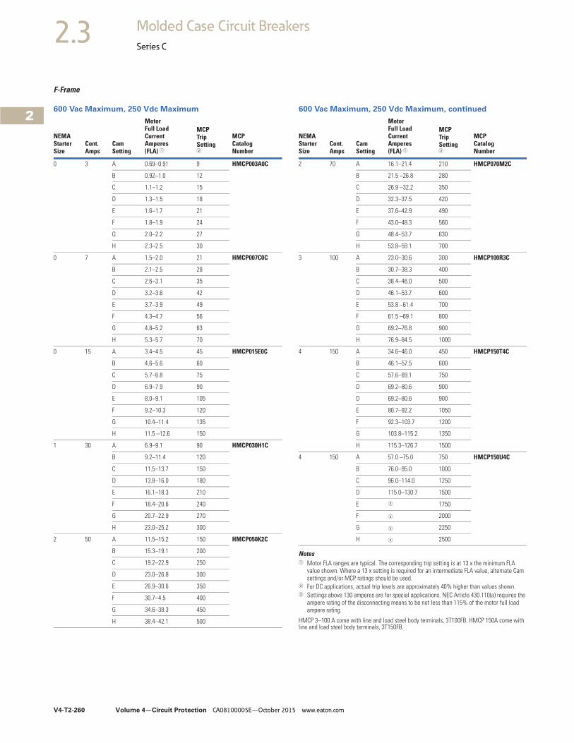
V4-T2-260 Volume 4—Circuit Protection CA08100005E—October 2015 www.eaton.com
2
2
2
2
2
2
2
2
2
2
2
2
2
2
2
2
2
2
2
2
2
2
2
2
2
2
2
2
2
2
2.3 Molded Case Circuit Breakers
Series C
F-Frame
600 Vac Maximum, 250 Vdc Maximum 600 Vac Maximum, 250 Vdc Maximum, continued
Notes1 Motor FLA ranges are typical. The corresponding trip setting is at 13 x the minimum FLA
value shown. Where a 13 x setting is required for an intermediate FLA value, alternate Cam settings and/or MCP ratings should be used.
2 For DC applications, actual trip levels are approximately 40% higher than values shown.3 Settings above 130 amperes are for special applications. NEC Article 430.110(a) requires the
ampere rating of the disconnecting means to be not less than 115% of the motor full load ampere rating.
HMCP 3–100 A come with line and load steel body terminals, 3T100FB. HMCP 150A come with line and load steel body terminals, 3T150FB.
NEMAStarterSize
Cont.Amps
CamSetting
MotorFull LoadCurrentAmperes(FLA) 1
MCPTripSetting2
MCPCatalogNumber
0 3 A 0.69–0.91 9 HMCP003A0C
B 0.92–1.0 12
C 1.1–1.2 15
D 1.3–1.5 18
E 1.6–1.7 21
F 1.8–1.9 24
G 2.0–2.2 27
H 2.3–2.5 30
0 7 A 1.5–2.0 21 HMCP007C0C
B 2.1–2.5 28
C 2.6–3.1 35
D 3.2–3.6 42
E 3.7–3.9 49
F 4.3–4.7 56
G 4.8–5.2 63
H 5.3–5.7 70
0 15 A 3.4–4.5 45 HMCP015E0C
B 4.6–5.6 60
C 5.7–6.8 75
D 6.9–7.9 90
E 8.0–9.1 105
F 9.2–10.3 120
G 10.4–11.4 135
H 11.5 –12.6 150
1 30 A 6.9–9.1 90 HMCP030H1C
B 9.2–11.4 120
C 11.5–13.7 150
D 13.8–16.0 180
E 16.1–18.3 210
F 18.4–20.6 240
G 20.7–22.9 270
H 23.0–25.2 300
2 50 A 11.5–15.2 150 HMCP050K2C
B 15.3–19.1 200
C 19.2–22.9 250
D 23.0–26.8 300
E 26.9–30.6 350
F 30.7–4.5 400
G 34.6–38.3 450
H 38.4–42.1 500
NEMAStarterSize
Cont.Amps
CamSetting
MotorFull LoadCurrentAmperes(FLA) 1
MCPTripSetting2
MCPCatalogNumber
2 70 A 16.1–21.4 210 HMCP070M2C
B 21.5 –26.8 280
C 26.9 –32.2 350
D 32.3–37.5 420
E 37.6–42.9 490
F 43.0–48.3 560
G 48.4–53.7 630
H 53.8–59.1 700
3 100 A 23.0–30.6 300 HMCP100R3C
B 30.7–38.3 400
C 38.4–46.0 500
D 46.1–53.7 600
E 53.8 –61.4 700
F 61.5 –69.1 800
G 69.2–76.8 900
H 76.9–84.5 1000
4 150 A 34.6–46.0 450 HMCP150T4C
B 46.1–57.5 600
C 57.6–69.1 750
D 69.2–80.6 900
D 69.2–80.6 900
E 80.7–92.2 1050
F 92.3–103.7 1200
G 103.8–115.2 1350
H 115.3–126.7 1500
4 150 A 57.0 –75.0 750 HMCP150U4C
B 76.0–95.0 1000
C 96.0–114.0 1250
D 115.0–130.7 1500
E 3 1750
F 3 2000
G 3 2250
H 3 2500
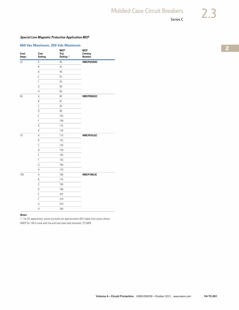
Volume 4—Circuit Protection CA08100005E—October 2015 www.eaton.com V4-T2-261
2
2
2
2
2
2
2
2
2
2
2
2
2
2
2
2
2
2
2
2
2
2
2
2
2
2
2
2
2
2
2.3Molded Case Circuit Breakers
Series C
Special Low Magnetic Protection Application MCP
600 Vac Maximum, 250 Vdc Maximum
Notes1 For DC applications, actual trip levels are approximately 40% higher than values shown.
HMCP 25–100 A come with line and load steel body terminals, 3T100FB.
Cont.Amps
CamSetting
MCPTripSetting 1
MCPCatalogNumber
25 A 40 HMCP025D0C
B 43
D 49
E 52
F 55
G 58
H 60
50 A 80 HMCP050G2C
B 87
C 93
D 98
E 103
F 109
G 115
H 120
70 A 115 HMCP070J2C
B 122
C 130
D 139
E 145
F 153
G 160
H 170
100 A 160 HMCP100L3C
B 174
C 185
D 196
E 207
F 218
G 229
H 240
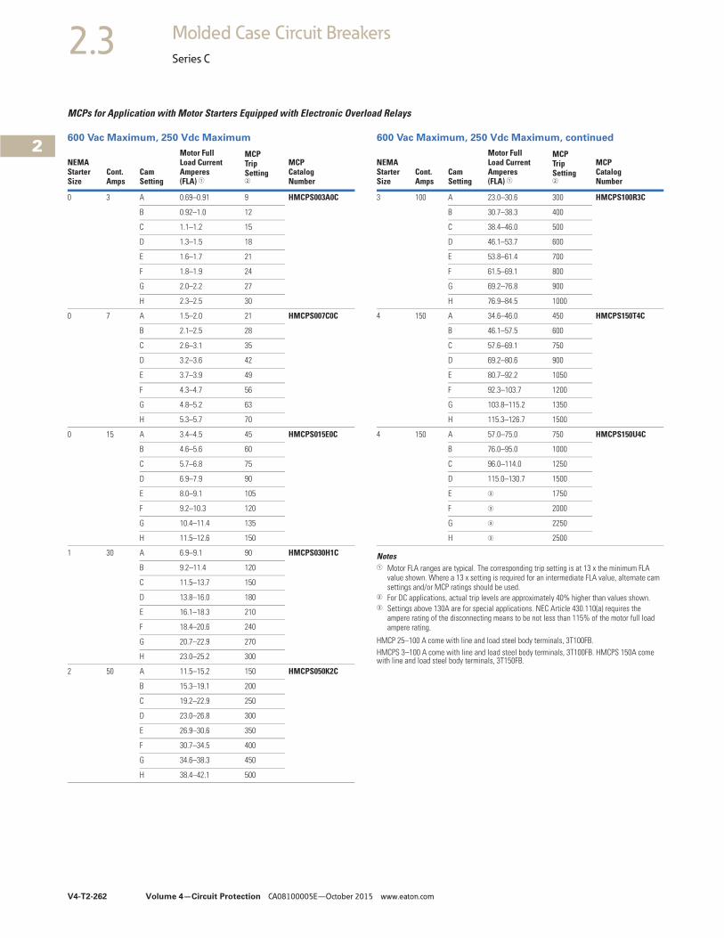
V4-T2-262 Volume 4—Circuit Protection CA08100005E—October 2015 www.eaton.com
2
2
2
2
2
2
2
2
2
2
2
2
2
2
2
2
2
2
2
2
2
2
2
2
2
2
2
2
2
2
2.3 Molded Case Circuit Breakers
Series C
MCPs for Application with Motor Starters Equipped with Electronic Overload Relays
600 Vac Maximum, 250 Vdc Maximum 600 Vac Maximum, 250 Vdc Maximum, continued
Notes1 Motor FLA ranges are typical. The corresponding trip setting is at 13 x the minimum FLA
value shown. Where a 13 x setting is required for an intermediate FLA value, alternate cam settings and/or MCP ratings should be used.
2 For DC applications, actual trip levels are approximately 40% higher than values shown.3 Settings above 130A are for special applications. NEC Article 430.110(a) requires the
ampere rating of the disconnecting means to be not less than 115% of the motor full load ampere rating.
HMCP 25–100 A come with line and load steel body terminals, 3T100FB.HMCPS 3–100 A come with line and load steel body terminals, 3T100FB. HMCPS 150A come with line and load steel body terminals, 3T150FB.
NEMAStarterSize
Cont.Amps
CamSetting
Motor FullLoad CurrentAmperes(FLA) 1
MCPTripSetting2
MCPCatalogNumber
0 3 A 0.69–0.91 9 HMCPS003A0C
B 0.92–1.0 12
C 1.1–1.2 15
D 1.3–1.5 18
E 1.6–1.7 21
F 1.8–1.9 24
G 2.0–2.2 27
H 2.3–2.5 30
0 7 A 1.5–2.0 21 HMCPS007C0C
B 2.1–2.5 28
C 2.6–3.1 35
D 3.2–3.6 42
E 3.7–3.9 49
F 4.3–4.7 56
G 4.8–5.2 63
H 5.3–5.7 70
0 15 A 3.4–4.5 45 HMCPS015E0C
B 4.6–5.6 60
C 5.7–6.8 75
D 6.9–7.9 90
E 8.0–9.1 105
F 9.2–10.3 120
G 10.4–11.4 135
H 11.5–12.6 150
1 30 A 6.9–9.1 90 HMCPS030H1C
B 9.2–11.4 120
C 11.5–13.7 150
D 13.8–16.0 180
E 16.1–18.3 210
F 18.4–20.6 240
G 20.7–22.9 270
H 23.0–25.2 300
2 50 A 11.5–15.2 150 HMCPS050K2C
B 15.3–19.1 200
C 19.2–22.9 250
D 23.0–26.8 300
E 26.9–30.6 350
F 30.7–34.5 400
G 34.6–38.3 450
H 38.4–42.1 500
NEMAStarterSize
Cont.Amps
CamSetting
Motor FullLoad CurrentAmperes(FLA) 1
MCPTripSetting2
MCPCatalogNumber
3 100 A 23.0–30.6 300 HMCPS100R3C
B 30.7–38.3 400
C 38.4–46.0 500
D 46.1–53.7 600
E 53.8–61.4 700
F 61.5–69.1 800
G 69.2–76.8 900
H 76.9–84.5 1000
4 150 A 34.6–46.0 450 HMCPS150T4C
B 46.1–57.5 600
C 57.6–69.1 750
D 69.2–80.6 900
E 80.7–92.2 1050
F 92.3–103.7 1200
G 103.8–115.2 1350
H 115.3–126.7 1500
4 150 A 57.0–75.0 750 HMCPS150U4C
B 76.0–95.0 1000
C 96.0–114.0 1250
D 115.0–130.7 1500
E 3 1750
F 3 2000
G 3 2250
H 3 2500
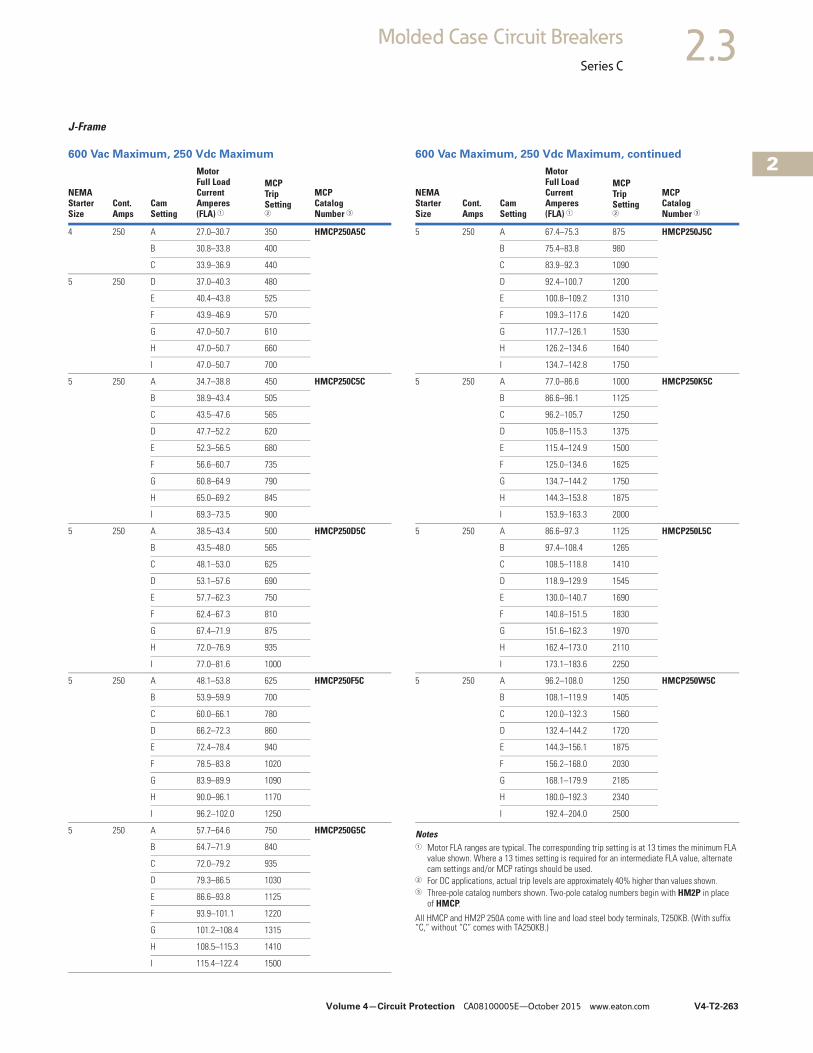
Volume 4—Circuit Protection CA08100005E—October 2015 www.eaton.com V4-T2-263
2
2
2
2
2
2
2
2
2
2
2
2
2
2
2
2
2
2
2
2
2
2
2
2
2
2
2
2
2
2
2.3Molded Case Circuit Breakers
Series C
J-Frame
600 Vac Maximum, 250 Vdc Maximum 600 Vac Maximum, 250 Vdc Maximum, continued
Notes1 Motor FLA ranges are typical. The corresponding trip setting is at 13 times the minimum FLA
value shown. Where a 13 times setting is required for an intermediate FLA value, alternate cam settings and/or MCP ratings should be used.
2 For DC applications, actual trip levels are approximately 40% higher than values shown.3 Three-pole catalog numbers shown. Two-pole catalog numbers begin with HM2P in place
of HMCP.
All HMCP and HM2P 250A come with line and load steel body terminals, T250KB. (With suffix “C,” without “C” comes with TA250KB.)
NEMAStarterSize
Cont.Amps
CamSetting
MotorFull LoadCurrentAmperes(FLA) 1
MCPTripSetting2
MCPCatalogNumber 3
4 250 A 27.0–30.7 350 HMCP250A5C
B 30.8–33.8 400
C 33.9–36.9 440
5 250 D 37.0–40.3 480
E 40.4–43.8 525
F 43.9–46.9 570
G 47.0–50.7 610
H 47.0–50.7 660
I 47.0–50.7 700
5 250 A 34.7–38.8 450 HMCP250C5C
B 38.9–43.4 505
C 43.5–47.6 565
D 47.7–52.2 620
E 52.3–56.5 680
F 56.6–60.7 735
G 60.8–64.9 790
H 65.0–69.2 845
I 69.3–73.5 900
5 250 A 38.5–43.4 500 HMCP250D5C
B 43.5–48.0 565
C 48.1–53.0 625
D 53.1–57.6 690
E 57.7–62.3 750
F 62.4–67.3 810
G 67.4–71.9 875
H 72.0–76.9 935
I 77.0–81.6 1000
5 250 A 48.1–53.8 625 HMCP250F5C
B 53.9–59.9 700
C 60.0–66.1 780
D 66.2–72.3 860
E 72.4–78.4 940
F 78.5–83.8 1020
G 83.9–89.9 1090
H 90.0–96.1 1170
I 96.2–102.0 1250
5 250 A 57.7–64.6 750 HMCP250G5C
B 64.7–71.9 840
C 72.0–79.2 935
D 79.3–86.5 1030
E 86.6–93.8 1125
F 93.9–101.1 1220
G 101.2–108.4 1315
H 108.5–115.3 1410
I 115.4–122.4 1500
NEMAStarterSize
Cont.Amps
CamSetting
MotorFull LoadCurrentAmperes(FLA) 1
MCPTripSetting2
MCPCatalogNumber 3
5 250 A 67.4–75.3 875 HMCP250J5C
B 75.4–83.8 980
C 83.9–92.3 1090
D 92.4–100.7 1200
E 100.8–109.2 1310
F 109.3–117.6 1420
G 117.7–126.1 1530
H 126.2–134.6 1640
I 134.7–142.8 1750
5 250 A 77.0–86.6 1000 HMCP250K5C
B 86.6–96.1 1125
C 96.2–105.7 1250
D 105.8–115.3 1375
E 115.4–124.9 1500
F 125.0–134.6 1625
G 134.7–144.2 1750
H 144.3–153.8 1875
I 153.9–163.3 2000
5 250 A 86.6–97.3 1125 HMCP250L5C
B 97.4–108.4 1265
C 108.5–118.8 1410
D 118.9–129.9 1545
E 130.0–140.7 1690
F 140.8–151.5 1830
G 151.6–162.3 1970
H 162.4–173.0 2110
I 173.1–183.6 2250
5 250 A 96.2–108.0 1250 HMCP250W5C
B 108.1–119.9 1405
C 120.0–132.3 1560
D 132.4–144.2 1720
E 144.3–156.1 1875
F 156.2–168.0 2030
G 168.1–179.9 2185
H 180.0–192.3 2340
I 192.4–204.0 2500
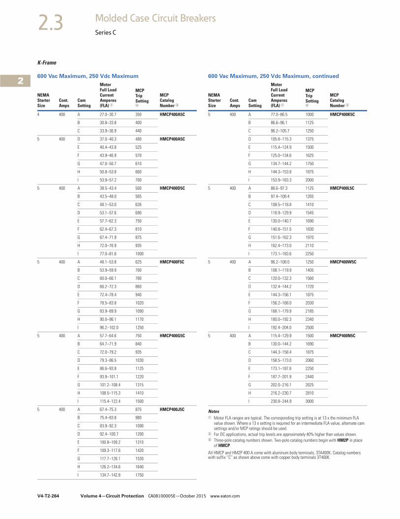
V4-T2-264 Volume 4—Circuit Protection CA08100005E—October 2015 www.eaton.com
2
2
2
2
2
2
2
2
2
2
2
2
2
2
2
2
2
2
2
2
2
2
2
2
2
2
2
2
2
2
2.3 Molded Case Circuit Breakers
Series C
K-Frame
600 Vac Maximum, 250 Vdc Maximum 600 Vac Maximum, 250 Vdc Maximum, continued
Notes1 Motor FLA ranges are typical. The corresponding trip setting is at 13 x the minimum FLA
value shown. Where a 13 x setting is required for an intermediate FLA value, alternate cam settings and/or MCP ratings should be used.
2 For DC applications, actual trip levels are approximately 40% higher than values shown.3 Three-pole catalog numbers shown. Two-pole catalog numbers begin with HM2P in place
of HMCP.
All HMCP and HM2P 400 A come with aluminum body terminals, 3TA400K. Catalog numbers with suffix “C” as shown above come with copper body terminals 3T400K.
NEMAStarterSize
Cont.Amps
CamSetting
MotorFull LoadCurrentAmperes(FLA) 1
MCPTripSetting2
MCPCatalogNumber 3
4 400 A 27.0–30.7 350 HMCP400A5C
B 30.8–33.8 400
C 33.9–36.9 440
5 400 D 37.0–40.3 480 HMCP400A5C
E 40.4–43.8 525
F 43.9–46.9 570
G 47.0–50.7 610
H 50.8–53.8 660
I 53.9–57.2 700
5 400 A 38.5–43.4 500 HMCP400D5C
B 43.5–48.0 565
C 48.1–53.0 626
D 53.1–57.6 690
E 57.7–62.3 750
F 62.4–67.3 810
G 67.4–71.9 875
H 72.0–76.9 935
I 77.0–81.6 1000
5 400 A 48.1–53.8 625 HMCP400F5C
B 53.9–59.9 700
C 60.0–66.1 780
D 66.2–72.3 860
E 72.4–78.4 940
F 78.5–83.8 1020
G 83.9–89.9 1090
H 90.0–96.1 1170
I 96.2–102.0 1250
5 400 A 57.7–64.6 750 HMCP400G5C
B 64.7–71.9 840
C 72.0–79.2 935
D 79.3–86.5 1030
E 86.6–93.8 1125
F 93.9–101.1 1220
G 101.2–108.4 1315
H 108.5–115.3 1410
I 115.4–122.4 1500
5 400 A 67.4–75.3 875 HMCP400J5C
B 75.4–83.8 980
C 83.9–92.3 1090
D 92.4–100.7 1200
E 100.8–109.2 1310
F 109.3–117.6 1420
G 117.7–126.1 1530
H 126.2–134.6 1640
I 134.7–142.8 1750
NEMAStarterSize
Cont.Amps
CamSetting
MotorFull LoadCurrentAmperes(FLA) 1
MCPTripSetting2
MCPCatalogNumber 3
5 400 A 77.0–86.5 1000 HMCP400K5C
B 86.6–96.1 1125
C 96.2–105.7 1250
D 105.8–115.3 1375
E 115.4–124.9 1500
F 125.0–134.6 1625
G 134.7–144.2 1750
H 144.3–153.8 1875
I 153.9–163.3 2000
5 400 A 86.6–97.3 1125 HMCP400L5C
B 97.4–108.4 1265
C 108.5–118.8 1410
D 118.9–129.9 1545
E 130.0–140.7 1690
F 140.8–151.5 1830
G 151.6–162.3 1970
H 162.4–173.0 2110
I 173.1–183.6 2250
5 400 A 96.2–108.0 1250 HMCP400W5C
B 108.1–119.9 1405
C 120.0–132.3 1560
D 132.4–144.2 1720
E 144.3–156.1 1875
F 156.2–168.0 2030
G 168.1–179.9 2185
H 180.0–192.3 2340
I 192.4–204.0 2500
5 400 A 115.4–129.9 1500 HMCP400N5C
B 130.0–144.2 1690
C 144.3–158.4 1875
D 158.5–173.0 2060
E 173.1–187.6 2250
F 187.7–201.9 2440
G 202.0–216.1 2625
H 216.2–230.7 2810
I 230.8–244.9 3000
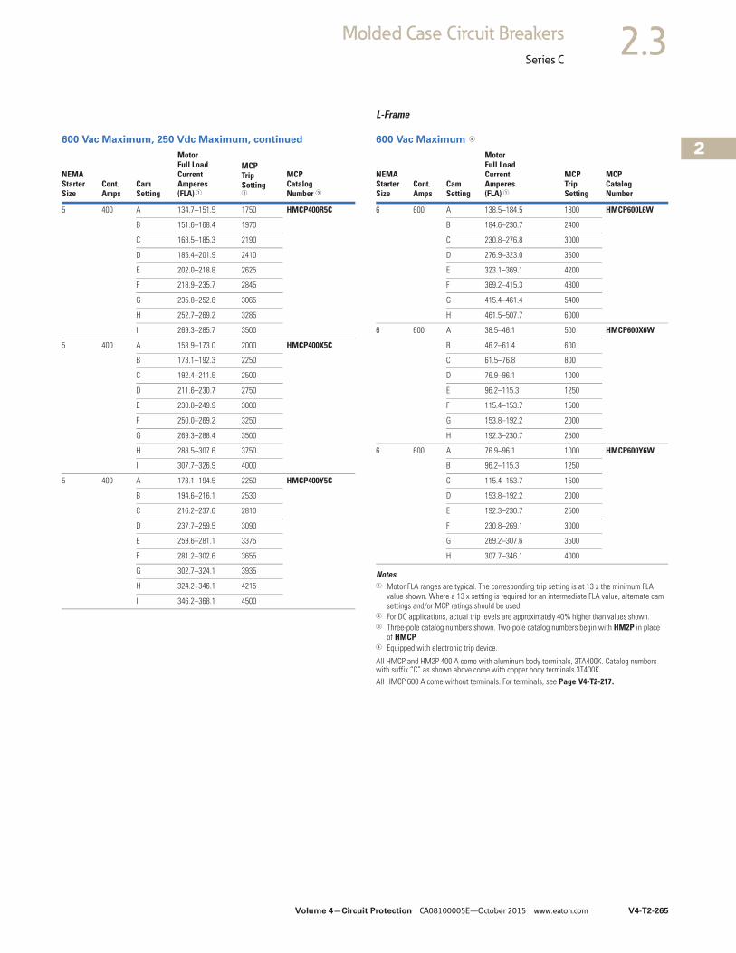
Volume 4—Circuit Protection CA08100005E—October 2015 www.eaton.com V4-T2-265
2
2
2
2
2
2
2
2
2
2
2
2
2
2
2
2
2
2
2
2
2
2
2
2
2
2
2
2
2
2
2.3Molded Case Circuit Breakers
Series C
600 Vac Maximum, 250 Vdc Maximum, continued
L-Frame
600 Vac Maximum 4
Notes1 Motor FLA ranges are typical. The corresponding trip setting is at 13 x the minimum FLA
value shown. Where a 13 x setting is required for an intermediate FLA value, alternate cam settings and/or MCP ratings should be used.
2 For DC applications, actual trip levels are approximately 40% higher than values shown.3 Three-pole catalog numbers shown. Two-pole catalog numbers begin with HM2P in place
of HMCP.4 Equipped with electronic trip device.
All HMCP and HM2P 400 A come with aluminum body terminals, 3TA400K. Catalog numbers with suffix “C” as shown above come with copper body terminals 3T400K.All HMCP 600 A come without terminals. For terminals, see Page V4-T2-217.
NEMAStarterSize
Cont.Amps
CamSetting
MotorFull LoadCurrentAmperes(FLA) 1
MCPTripSetting2
MCPCatalogNumber 3
5 400 A 134.7–151.5 1750 HMCP400R5C
B 151.6–168.4 1970
C 168.5–185.3 2190
D 185.4–201.9 2410
E 202.0–218.8 2625
F 218.9–235.7 2845
G 235.8–252.6 3065
H 252.7–269.2 3285
I 269.3–285.7 3500
5 400 A 153.9–173.0 2000 HMCP400X5C
B 173.1–192.3 2250
C 192.4–211.5 2500
D 211.6–230.7 2750
E 230.8–249.9 3000
F 250.0–269.2 3250
G 269.3–288.4 3500
H 288.5–307.6 3750
I 307.7–326.9 4000
5 400 A 173.1–194.5 2250 HMCP400Y5C
B 194.6–216.1 2530
C 216.2–237.6 2810
D 237.7–259.5 3090
E 259.6–281.1 3375
F 281.2–302.6 3655
G 302.7–324.1 3935
H 324.2–346.1 4215
I 346.2–368.1 4500
NEMAStarterSize
Cont.Amps
CamSetting
MotorFull LoadCurrentAmperes(FLA) 1
MCPTripSetting
MCPCatalogNumber
6 600 A 138.5–184.5 1800 HMCP600L6W
B 184.6–230.7 2400
C 230.8–276.8 3000
D 276.9–323.0 3600
E 323.1–369.1 4200
F 369.2–415.3 4800
G 415.4–461.4 5400
H 461.5–507.7 6000
6 600 A 38.5–46.1 500 HMCP600X6W
B 46.2–61.4 600
C 61.5–76.8 800
D 76.9–96.1 1000
E 96.2–115.3 1250
F 115.4–153.7 1500
G 153.8–192.2 2000
H 192.3–230.7 2500
6 600 A 76.9–96.1 1000 HMCP600Y6W
B 96.2–115.3 1250
C 115.4–153.7 1500
D 153.8–192.2 2000
E 192.3–230.7 2500
F 230.8–269.1 3000
G 269.2–307.6 3500
H 307.7–346.1 4000
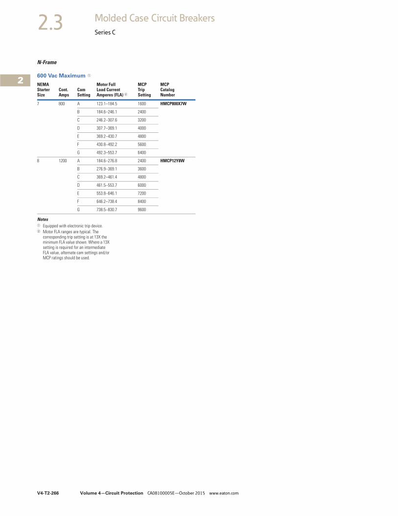
V4-T2-266 Volume 4—Circuit Protection CA08100005E—October 2015 www.eaton.com
2
2
2
2
2
2
2
2
2
2
2
2
2
2
2
2
2
2
2
2
2
2
2
2
2
2
2
2
2
2
2.3 Molded Case Circuit Breakers
Series C
N-Frame
600 Vac Maximum 1
Notes1 Equipped with electronic trip device.2 Motor FLA ranges are typical. The
corresponding trip setting is at 13X the minimum FLA value shown. Where a 13X setting is required for an intermediate FLA value, alternate cam settings and/or MCP ratings should be used.
NEMAStarterSize
Cont.Amps
CamSetting
Motor Full Load CurrentAmperes (FLA) 2
MCPTripSetting
MCPCatalogNumber
7 800 A 123.1–184.5 1600 HMCP800X7W
B 184.6–246.1 2400
C 246.2–307.6 3200
D 307.7–369.1 4000
E 369.2–430.7 4800
F 430.8–492.2 5600
G 492.3–553.7 6400
8 1200 A 184.6–276.8 2400 HMCP12Y8W
B 276.9–369.1 3600
C 369.2–461.4 4800
D 461.5–553.7 6000
E 553.8–646.1 7200
F 646.2–738.4 8400
G 738.5–830.7 9600
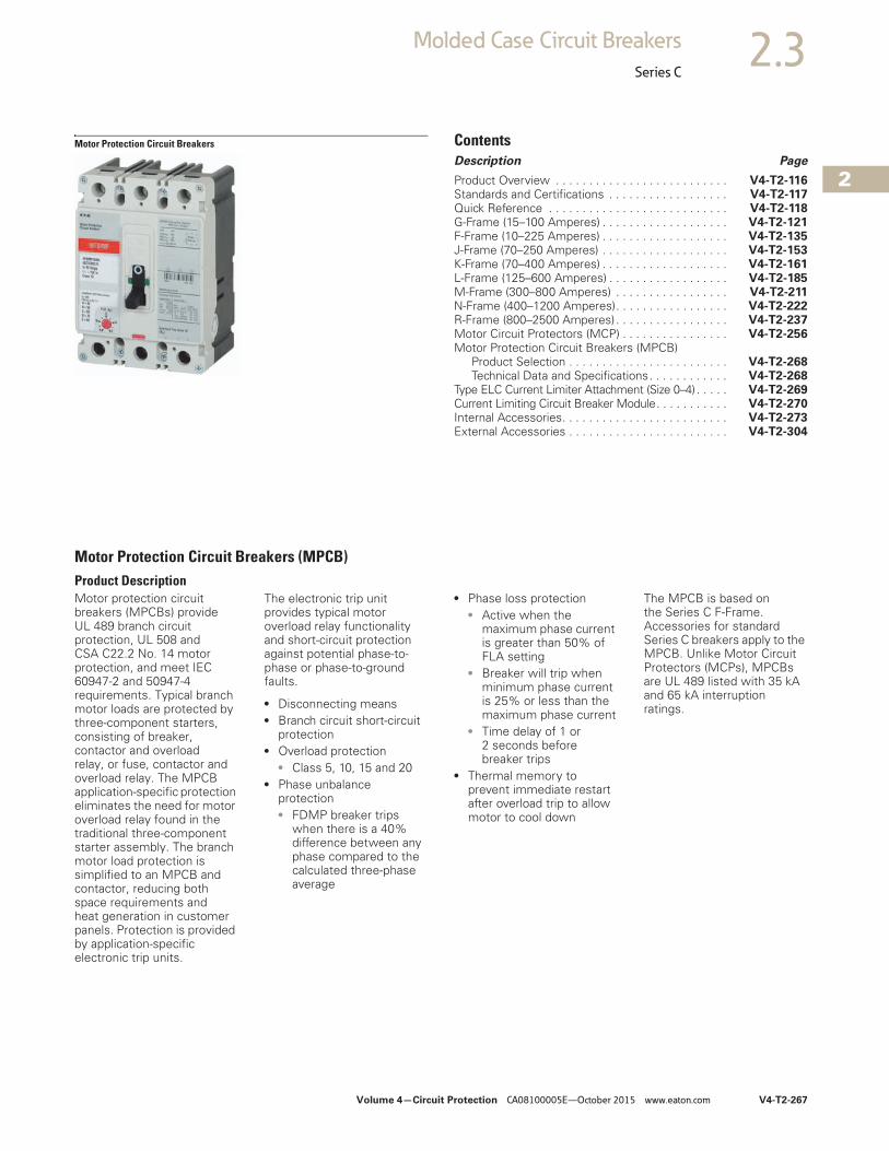
Volume 4—Circuit Protection CA08100005E—October 2015 www.eaton.com V4-T2-267
2
2
2
2
2
2
2
2
2
2
2
2
2
2
2
2
2
2
2
2
2
2
2
2
2
2
2
2
2
2
2.3Molded Case Circuit Breakers
Series C
Motor Protection Circuit Breakers ContentsDescription Page
Product Overview . . . . . . . . . . . . . . . . . . . . . . . . . . V4-T2-116Standards and Certifications . . . . . . . . . . . . . . . . . . V4-T2-117Quick Reference . . . . . . . . . . . . . . . . . . . . . . . . . . . V4-T2-118G-Frame (15–100 Amperes) . . . . . . . . . . . . . . . . . . . V4-T2-121F-Frame (10–225 Amperes) . . . . . . . . . . . . . . . . . . . V4-T2-135J-Frame (70–250 Amperes) . . . . . . . . . . . . . . . . . . . V4-T2-153K-Frame (70–400 Amperes) . . . . . . . . . . . . . . . . . . . V4-T2-161L-Frame (125–600 Amperes) . . . . . . . . . . . . . . . . . . V4-T2-185M-Frame (300–800 Amperes) . . . . . . . . . . . . . . . . . V4-T2-211N-Frame (400–1200 Amperes). . . . . . . . . . . . . . . . . V4-T2-222R-Frame (800–2500 Amperes) . . . . . . . . . . . . . . . . . V4-T2-237Motor Circuit Protectors (MCP) . . . . . . . . . . . . . . . . V4-T2-256Motor Protection Circuit Breakers (MPCB)
Product Selection . . . . . . . . . . . . . . . . . . . . . . . . V4-T2-268Technical Data and Specifications. . . . . . . . . . . . V4-T2-268
Type ELC Current Limiter Attachment (Size 0–4) . . . . . V4-T2-269Current Limiting Circuit Breaker Module. . . . . . . . . . . V4-T2-270Internal Accessories. . . . . . . . . . . . . . . . . . . . . . . . . V4-T2-273External Accessories . . . . . . . . . . . . . . . . . . . . . . . . V4-T2-304
Motor Protection Circuit Breakers (MPCB)Product DescriptionMotor protection circuit breakers (MPCBs) provide UL 489 branch circuit protection, UL 508 and CSA C22.2 No. 14 motor protection, and meet IEC 60947-2 and 50947-4 requirements. Typical branch motor loads are protected by three-component starters, consisting of breaker, contactor and overload relay, or fuse, contactor and overload relay. The MPCB application-specific protection eliminates the need for motor overload relay found in the traditional three-component starter assembly. The branch motor load protection is simplified to an MPCB and contactor, reducing both space requirements and heat generation in customer panels. Protection is provided by application-specific electronic trip units.
The electronic trip unit provides typical motor overload relay functionality and short-circuit protection against potential phase-to-phase or phase-to-ground faults.
● Disconnecting means● Branch circuit short-circuit
protection● Overload protection
● Class 5, 10, 15 and 20● Phase unbalance
protection● FDMP breaker trips
when there is a 40% difference between any phase compared to the calculated three-phase average
● Phase loss protection● Active when the
maximum phase current is greater than 50% of FLA setting
● Breaker will trip when minimum phase current is 25% or less than the maximum phase current
● Time delay of 1 or 2 seconds before breaker trips
● Thermal memory to prevent immediate restart after overload trip to allow motor to cool down
The MPCB is based on the Series C F-Frame. Accessories for standard Series C breakers apply to the MPCB. Unlike Motor Circuit Protectors (MCPs), MPCBs are UL 489 listed with 35 kA and 65 kA interruption ratings.
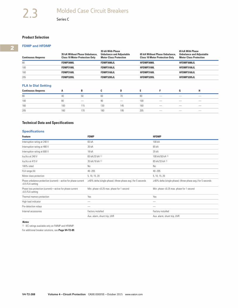
V4-T2-268 Volume 4—Circuit Protection CA08100005E—October 2015 www.eaton.com
2
2
2
2
2
2
2
2
2
2
2
2
2
2
2
2
2
2
2
2
2
2
2
2
2
2
2
2
2
2
2.3 Molded Case Circuit Breakers
Series C
Product Selection
FDMP and HFDMP
FLA le Dial Setting
Technical Data and Specifications
Specifications
Notes1 IEC ratings available only on FWMP and HFWMP.
For additional breaker solutions, see Page V4-T2-89.
Continuous Amperes35 kA Without Phase Unbalance, Class 10 Motor Protection Only
35 kA With Phase Unbalance and AdjustableMotor Class Protection
65 kA Without Phase Unbalance, Class 10 Motor Protection Only
65 kA With Phase Unbalance and Adjustable Motor Class Protection
80 FDMP3080L FDMP3080JL HFDMP3080L HFDMP3080JL
100 FDMP3100L FDMP3100JL HFDMP3100L HFDMP3100JL
160 FDMP3160L FDMP3160JL HFDMP3160L HFDMP3160JL
205 FDMP3205L FDMP3205JL HFDMP3205L HFDMP3205JL
Continuous Amperes A B C D E F G H
80 40 50 60 70 80 — — —
100 80 — 90 — 100 — — —
160 100 115 130 145 160 — — —
205 160 170 180 195 205 — — —
Feature FDMP HFDMP
Interruption rating at 240 V 65 kA 100 kA
Interruption rating at 480 V 35 kA 65 kA
Interruption rating at 600 V 18 kA 25 kA
Icu/Ics at 240 V 65 kA/33 kA 1 100 kA/50 kA 1
Icu/Ics at 415 V 35 kA/18 kA 1 65 kA/33 kA 1
100% rated No No
FLA range (A) 40–205 40–205
Motor class protection 5, 10, 15, 20 5, 10, 15, 20
Phase unbalance protection (current)—active for phase current >0.5 FLA setting
40% delta (single-phase): (three-phase avg.) for 5 seconds 40% delta (single-phase): (three-phase avg.) for 5 seconds
Phase loss protection (current)—active for phase current >0.5 FLA setting
Min. phase 0.25 max. phase for 1 second Min. phase 0.25 max. phase for 1 second
Thermal memory protection Yes Yes
High load indicator — —
Pre-detection relays — —
Internal accessories Factory installed Factory installed
Aux. alarm, shunt trip, UVR Aux. alarm, shunt trip, UVR
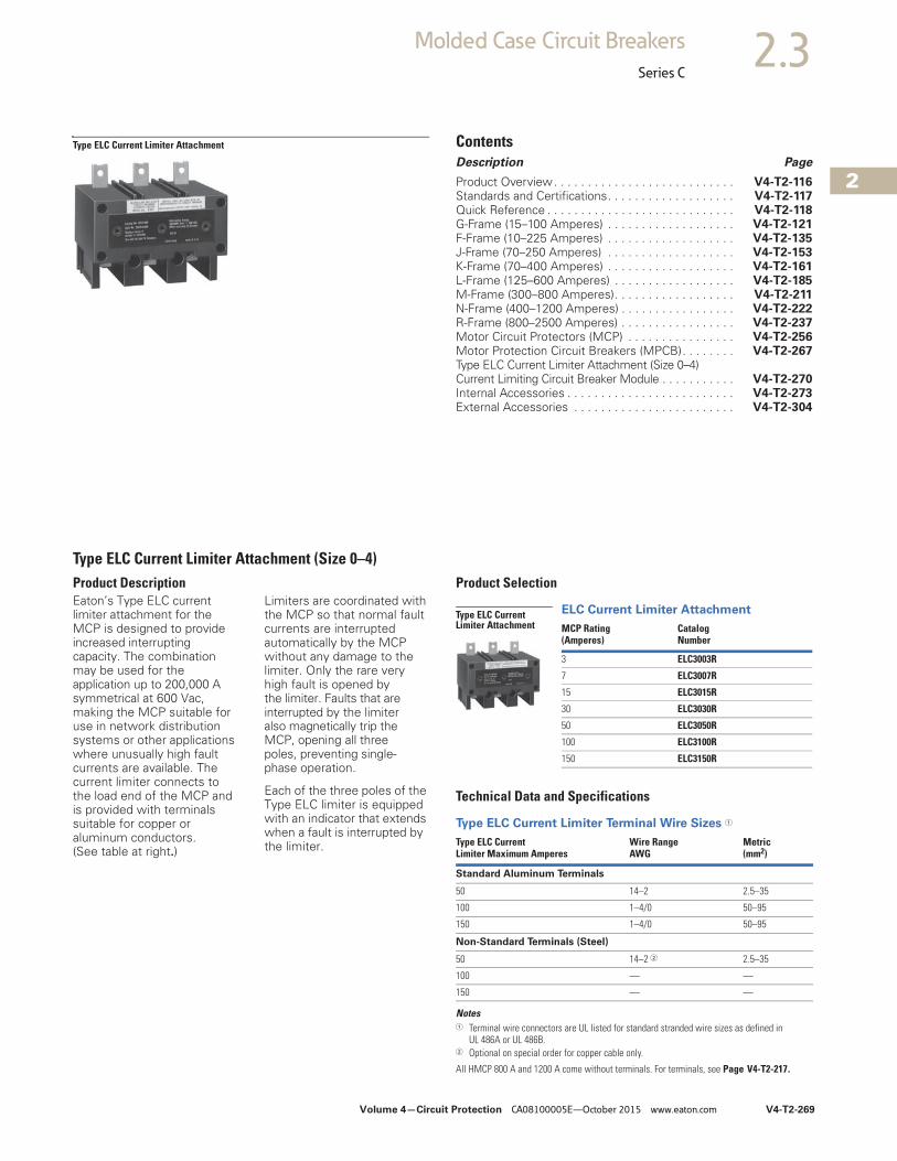
2
2
2
2
2
2
2
2
2
2
2
2
2
2
2
2
2
2
2
2
2
2
2
2
2
2
2
2
2
2
Volume 4—Circuit Protection CA08100005E—October 2015 www.eaton.com V4-T2-269
2.3Molded Case Circuit Breakers
Series C
Type ELC Current Limiter Attachment ContentsDescription Page
Product Overview. . . . . . . . . . . . . . . . . . . . . . . . . . . V4-T2-116Standards and Certifications. . . . . . . . . . . . . . . . . . . V4-T2-117Quick Reference . . . . . . . . . . . . . . . . . . . . . . . . . . . . V4-T2-118G-Frame (15–100 Amperes) . . . . . . . . . . . . . . . . . . . V4-T2-121F-Frame (10–225 Amperes) . . . . . . . . . . . . . . . . . . . V4-T2-135J-Frame (70–250 Amperes) . . . . . . . . . . . . . . . . . . . V4-T2-153K-Frame (70–400 Amperes) . . . . . . . . . . . . . . . . . . . V4-T2-161L-Frame (125–600 Amperes) . . . . . . . . . . . . . . . . . . V4-T2-185M-Frame (300–800 Amperes). . . . . . . . . . . . . . . . . . V4-T2-211N-Frame (400–1200 Amperes) . . . . . . . . . . . . . . . . . V4-T2-222R-Frame (800–2500 Amperes) . . . . . . . . . . . . . . . . . V4-T2-237Motor Circuit Protectors (MCP) . . . . . . . . . . . . . . . . V4-T2-256Motor Protection Circuit Breakers (MPCB). . . . . . . . V4-T2-267Type ELC Current Limiter Attachment (Size 0–4)Current Limiting Circuit Breaker Module . . . . . . . . . . . V4-T2-270Internal Accessories . . . . . . . . . . . . . . . . . . . . . . . . . V4-T2-273External Accessories . . . . . . . . . . . . . . . . . . . . . . . . V4-T2-304
Type ELC Current Limiter Attachment (Size 0–4)Product DescriptionEaton’s Type ELC current limiter attachment for the MCP is designed to provide increased interrupting capacity. The combination may be used for the application up to 200,000 A symmetrical at 600 Vac, making the MCP suitable for use in network distribution systems or other applications where unusually high fault currents are available. The current limiter connects to the load end of the MCP and is provided with terminals suitable for copper or aluminum conductors. (See table at right.)
Limiters are coordinated with the MCP so that normal fault currents are interrupted automatically by the MCP without any damage to the limiter. Only the rare very high fault is opened by the limiter. Faults that are interrupted by the limiter also magnetically trip the MCP, opening all three poles, preventing single-phase operation.
Each of the three poles of the Type ELC limiter is equipped with an indicator that extends when a fault is interrupted by the limiter.
Product Selection
ELC Current Limiter Attachment
Technical Data and Specifications
Type ELC Current Limiter Terminal Wire Sizes 1
Notes1 Terminal wire connectors are UL listed for standard stranded wire sizes as defined in
UL 486A or UL 486B.2 Optional on special order for copper cable only.
All HMCP 800 A and 1200 A come without terminals. For terminals, see Page V4-T2-217.
MCP Rating(Amperes)
Catalog Number
3 ELC3003R
7 ELC3007R
15 ELC3015R
30 ELC3030R
50 ELC3050R
100 ELC3100R
150 ELC3150R
Type ELC Current Limiter Maximum Amperes
Wire RangeAWG
Metric (mm2)
Standard Aluminum Terminals
50 14–2 2.5–35
100 1–4/0 50–95
150 1–4/0 50–95
Non-Standard Terminals (Steel)
50 14–2 2 2.5–35
100 — —
150 — —
Type ELC Current Limiter Attachment
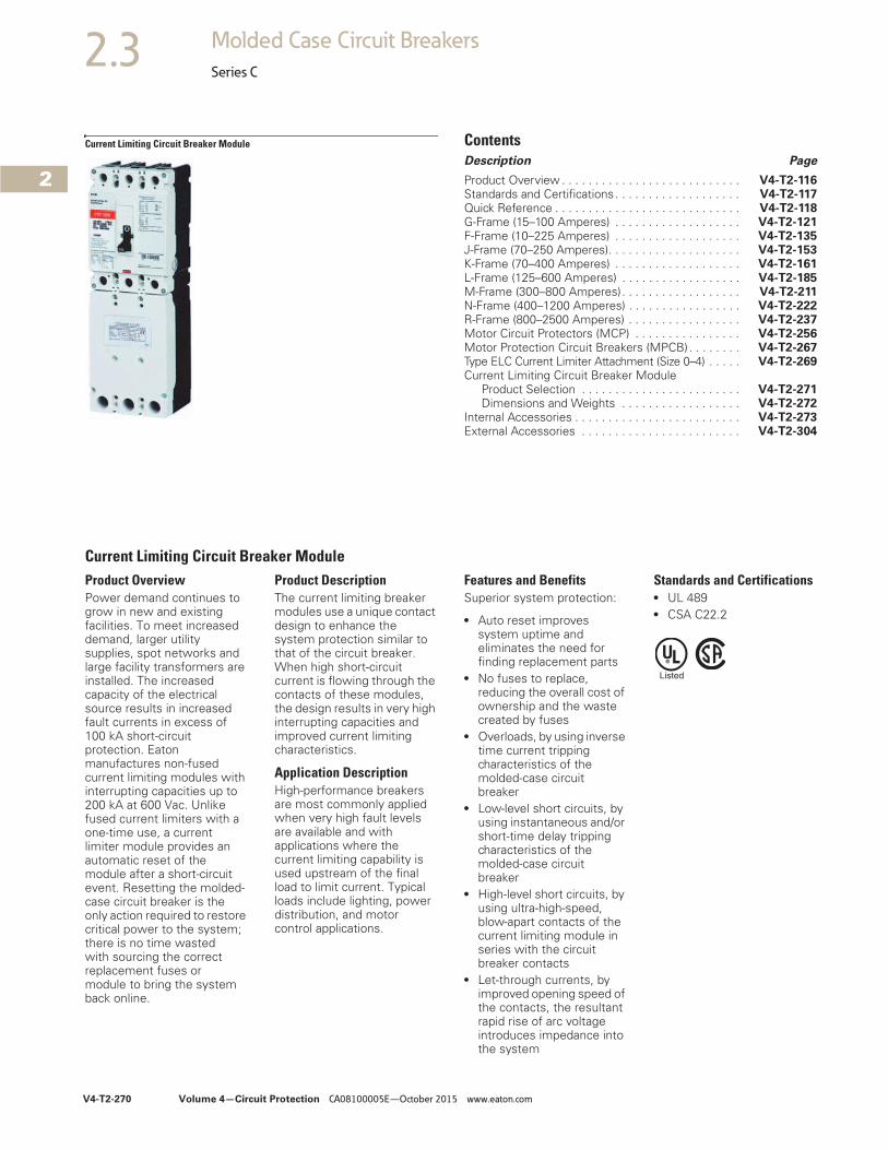
V4-T2-270 Volume 4—Circuit Protection CA08100005E—October 2015 www.eaton.com
2
2
2
2
2
2
2
2
2
2
2
2
2
2
2
2
2
2
2
2
2
2
2
2
2
2
2
2
2
2
2.3 Molded Case Circuit Breakers
Series C
Current Limiting Circuit Breaker Module ContentsDescription Page
Product Overview . . . . . . . . . . . . . . . . . . . . . . . . . . . V4-T2-116Standards and Certifications. . . . . . . . . . . . . . . . . . . V4-T2-117Quick Reference . . . . . . . . . . . . . . . . . . . . . . . . . . . . V4-T2-118G-Frame (15–100 Amperes) . . . . . . . . . . . . . . . . . . . V4-T2-121F-Frame (10–225 Amperes) . . . . . . . . . . . . . . . . . . . V4-T2-135J-Frame (70–250 Amperes). . . . . . . . . . . . . . . . . . . . V4-T2-153K-Frame (70–400 Amperes) . . . . . . . . . . . . . . . . . . . V4-T2-161L-Frame (125–600 Amperes) . . . . . . . . . . . . . . . . . . V4-T2-185M-Frame (300–800 Amperes). . . . . . . . . . . . . . . . . . V4-T2-211N-Frame (400–1200 Amperes) . . . . . . . . . . . . . . . . . V4-T2-222R-Frame (800–2500 Amperes) . . . . . . . . . . . . . . . . . V4-T2-237Motor Circuit Protectors (MCP) . . . . . . . . . . . . . . . . V4-T2-256Motor Protection Circuit Breakers (MPCB) . . . . . . . . V4-T2-267Type ELC Current Limiter Attachment (Size 0–4) . . . . . V4-T2-269Current Limiting Circuit Breaker Module
Product Selection . . . . . . . . . . . . . . . . . . . . . . . . V4-T2-271Dimensions and Weights . . . . . . . . . . . . . . . . . . V4-T2-272
Internal Accessories . . . . . . . . . . . . . . . . . . . . . . . . . V4-T2-273External Accessories . . . . . . . . . . . . . . . . . . . . . . . . V4-T2-304
Current Limiting Circuit Breaker ModuleProduct OverviewPower demand continues to grow in new and existing facilities. To meet increased demand, larger utility supplies, spot networks and large facility transformers are installed. The increased capacity of the electrical source results in increased fault currents in excess of 100 kA short-circuit protection. Eaton manufactures non-fused current limiting modules with interrupting capacities up to 200 kA at 600 Vac. Unlike fused current limiters with a one-time use, a current limiter module provides an automatic reset of the module after a short-circuit event. Resetting the molded-case circuit breaker is the only action required to restore critical power to the system; there is no time wasted with sourcing the correct replacement fuses or module to bring the system back online.
Product DescriptionThe current limiting breaker modules use a unique contact design to enhance the system protection similar to that of the circuit breaker. When high short-circuit current is flowing through the contacts of these modules, the design results in very high interrupting capacities and improved current limiting characteristics.
Application DescriptionHigh-performance breakers are most commonly applied when very high fault levels are available and with applications where the current limiting capability is used upstream of the final load to limit current. Typical loads include lighting, power distribution, and motor control applications.
Features and BenefitsSuperior system protection:
● Auto reset improves system uptime and eliminates the need for finding replacement parts
● No fuses to replace, reducing the overall cost of ownership and the waste created by fuses
● Overloads, by using inverse time current tripping characteristics of the molded-case circuit breaker
● Low-level short circuits, by using instantaneous and/or short-time delay tripping characteristics of the molded-case circuit breaker
● High-level short circuits, by using ultra-high-speed, blow-apart contacts of the current limiting module in series with the circuit breaker contacts
● Let-through currents, by improved opening speed of the contacts, the resultant rapid rise of arc voltage introduces impedance into the system
Standards and Certifications● UL 489 ● CSA C22.2
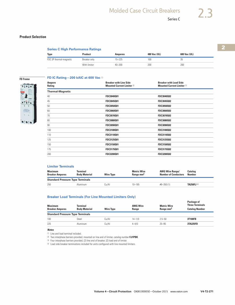
Volume 4—Circuit Protection CA08100005E—October 2015 www.eaton.com V4-T2-271
2
2
2
2
2
2
2
2
2
2
2
2
2
2
2
2
2
2
2
2
2
2
2
2
2
2
2
2
2
2
2.3Molded Case Circuit Breakers
Series C
Product Selection
Series C High Performance Ratings
FD IC Rating—200 kAIC at 600 Vac 1
Limiter Terminals
Breaker Load Terminals (For Line Mounted Limiters Only)
Notes1 Line and load terminal included.2 Two interphase barriers provided, mounted on line end of limiter, catalog number FJ1PBK.3 Four interphase barriers provided, (2) line end of breaker, (2) load end of limiter.4 Load side breaker terminations included for units configured with line mounted limiters.
Type Product Amperes 480 Vac (UL) 600 Vac (UL)
FDC 3P thermal-magnetic Breaker only 15–225 100 35
With limiter 40–200 200 200
Ampere Rating
Breaker with Line Side Mounted Current Limiter 2
Breaker with Load Side Mounted Current Limiter 3
Thermal-Magnetic
40 FDC3040Q01 FDC3040Q02
45 FDC3045Q01 FDC3045Q02
50 FDC3050Q01 FDC3050Q02
60 FDC3060Q01 FDC3060Q02
70 FDC3070Q01 FDC3070Q02
80 FDC3080Q01 FDC3080Q02
90 FDC3090Q01 FDC3090Q02
100 FDC3100Q01 FDC3100Q02
110 FDC3110Q01 FDC3110Q02
125 FDC3125Q01 FDC3125Q02
150 FDC3150Q01 FDC3150Q02
175 FDC3175Q01 FDC3175Q02
200 FDC3200Q01 FDC3200Q02
Maximum Breaker Amperes
Terminal Body Material Wire Type
Metric Wire Range mm2
AWG Wire Range/ Number of Conductors
CatalogNumber
Standard Pressure Type Terminals
250 Aluminum Cu/Al 10–185 #8–350 (1) TA250FJ 4
MaximumBreaker Amperes
Terminal Body Material Wire Type
AWG WireRange
Metric WireRange mm2
Package of Three TerminalsCatalog Number
Standard Pressure Type Terminals
100 Steel Cu/AI 14–1/0 2.5–50 3T100FB
225 Aluminum Cu/AI 4–4/0 25–95 3TA225FD
FD Frame
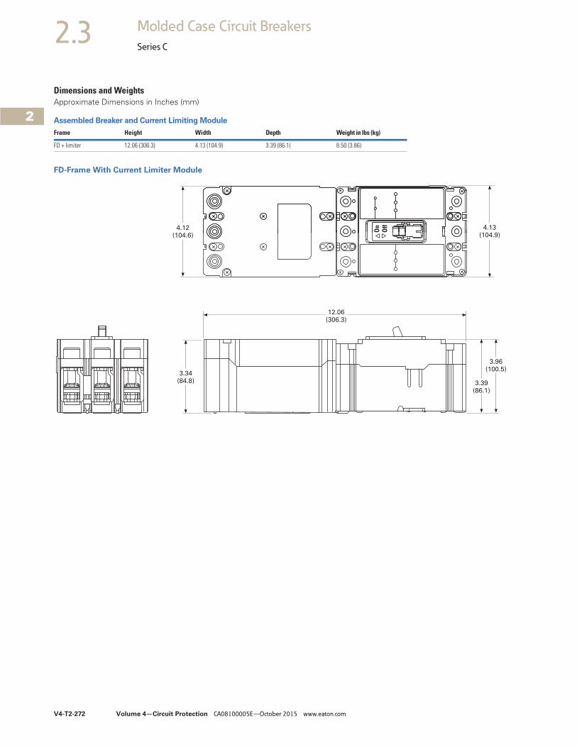
V4-T2-272 Volume 4—Circuit Protection CA08100005E—October 2015 www.eaton.com
2
2
2
2
2
2
2
2
2
2
2
2
2
2
2
2
2
2
2
2
2
2
2
2
2
2
2
2
2
2
2.3 Molded Case Circuit Breakers
Series C
Dimensions and WeightsApproximate Dimensions in Inches (mm)
Assembled Breaker and Current Limiting Module
FD-Frame With Current Limiter Module
Frame Height Width Depth Weight in lbs (kg)
FD + limiter 12.06 (306.3) 4.13 (104.9) 3.39 (86.1) 8.50 (3.86)
12.06(306.3)
3.34(84.8) 3.39
(86.1)
3.96(100.5)
4.12(104.6)
4.13(104.9)
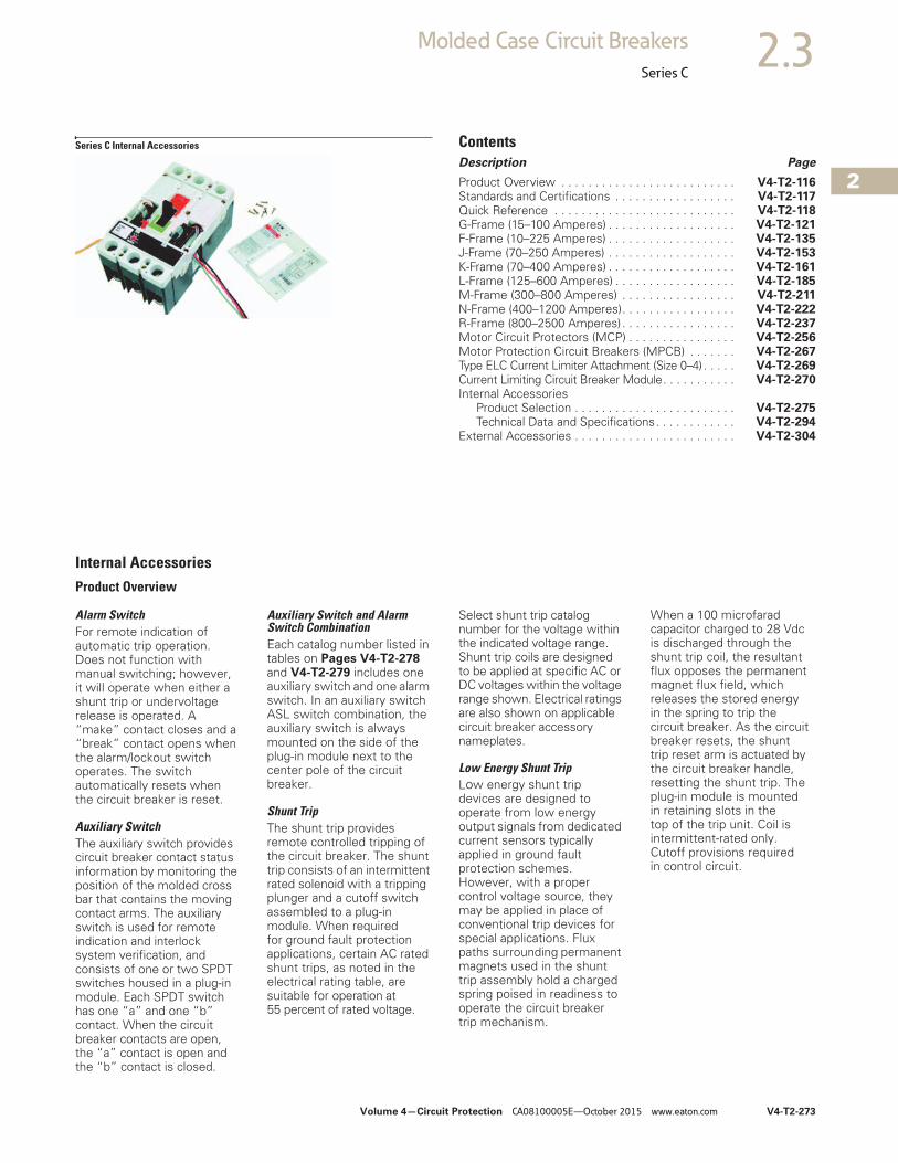
Volume 4—Circuit Protection CA08100005E—October 2015 www.eaton.com V4-T2-273
2
2
2
2
2
2
2
2
2
2
2
2
2
2
2
2
2
2
2
2
2
2
2
2
2
2
2
2
2
2
2.3Molded Case Circuit Breakers
Series C
Series C Internal Accessories ContentsDescription Page
Product Overview . . . . . . . . . . . . . . . . . . . . . . . . . . V4-T2-116Standards and Certifications . . . . . . . . . . . . . . . . . . V4-T2-117Quick Reference . . . . . . . . . . . . . . . . . . . . . . . . . . . V4-T2-118G-Frame (15–100 Amperes) . . . . . . . . . . . . . . . . . . . V4-T2-121F-Frame (10–225 Amperes) . . . . . . . . . . . . . . . . . . . V4-T2-135J-Frame (70–250 Amperes) . . . . . . . . . . . . . . . . . . . V4-T2-153K-Frame (70–400 Amperes) . . . . . . . . . . . . . . . . . . . V4-T2-161L-Frame (125–600 Amperes) . . . . . . . . . . . . . . . . . . V4-T2-185M-Frame (300–800 Amperes) . . . . . . . . . . . . . . . . . V4-T2-211N-Frame (400–1200 Amperes). . . . . . . . . . . . . . . . . V4-T2-222R-Frame (800–2500 Amperes) . . . . . . . . . . . . . . . . . V4-T2-237Motor Circuit Protectors (MCP) . . . . . . . . . . . . . . . . V4-T2-256Motor Protection Circuit Breakers (MPCB) . . . . . . . V4-T2-267Type ELC Current Limiter Attachment (Size 0–4) . . . . . V4-T2-269Current Limiting Circuit Breaker Module. . . . . . . . . . . V4-T2-270Internal Accessories
Product Selection . . . . . . . . . . . . . . . . . . . . . . . . V4-T2-275Technical Data and Specifications. . . . . . . . . . . . V4-T2-294
External Accessories . . . . . . . . . . . . . . . . . . . . . . . . V4-T2-304
Internal AccessoriesProduct Overview
Alarm SwitchFor remote indication of automatic trip operation. Does not function with manual switching; however, it will operate when either a shunt trip or undervoltage release is operated. A “make” contact closes and a “break” contact opens when the alarm/lockout switch operates. The switch automatically resets when the circuit breaker is reset.
Auxiliary SwitchThe auxiliary switch provides circuit breaker contact status information by monitoring the position of the molded cross bar that contains the moving contact arms. The auxiliary switch is used for remote indication and interlock system verification, and consists of one or two SPDT switches housed in a plug-in module. Each SPDT switch has one “a” and one “b” contact. When the circuit breaker contacts are open, the “a” contact is open and the “b” contact is closed.
Auxiliary Switch and Alarm Switch CombinationEach catalog number listed in tables on Pages V4-T2-278 and V4-T2-279 includes one auxiliary switch and one alarm switch. In an auxiliary switch ASL switch combination, the auxiliary switch is always mounted on the side of the plug-in module next to the center pole of the circuit breaker.
Shunt TripThe shunt trip provides remote controlled tripping of the circuit breaker. The shunt trip consists of an intermittent rated solenoid with a tripping plunger and a cutoff switch assembled to a plug-in module. When requiredfor ground fault protection applications, certain AC rated shunt trips, as noted in the electrical rating table, are suitable for operation at 55 percent of rated voltage.
Select shunt trip catalog number for the voltage within the indicated voltage range. Shunt trip coils are designed to be applied at specific AC or DC voltages within the voltage range shown. Electrical ratings are also shown on applicable circuit breaker accessory nameplates.
Low Energy Shunt TripLow energy shunt trip devices are designed to operate from low energy output signals from dedicated current sensors typically applied in ground fault protection schemes. However, with a proper control voltage source, they may be applied in place of conventional trip devices for special applications. Flux paths surrounding permanent magnets used in the shunt trip assembly hold a charged spring poised in readiness to operate the circuit breaker trip mechanism.
When a 100 microfarad capacitor charged to 28 Vdc is discharged through the shunt trip coil, the resultant flux opposes the permanent magnet flux field, which releases the stored energy in the spring to trip the circuit breaker. As the circuit breaker resets, the shunt trip reset arm is actuated by the circuit breaker handle, resetting the shunt trip. The plug-in module is mounted in retaining slots in the top of the trip unit. Coil is intermittent-rated only. Cutoff provisions required in control circuit.
V4-T2-274 Volume 4—Circuit Protection CA08100005E—October 2015 www.eaton.com
2
2
2
2
2
2
2
2
2
2
2
2
2
2
2
2
2
2
2
2
2
2
2
2
2
2
2
2
2
2
2.3 Molded Case Circuit Breakers
Series C
Undervoltage Release MechanismThe undervoltage release mechanism monitors a voltage (typically a line voltage) and trips the circuit breaker when the voltage falls to between 70 and 35 percent of the solenoid coil rating.
The undervoltage release mechanism consists of a continuous rated solenoid with a plunger and tripping lever mounted in a plug-in module. The tab on the tripping lever resets the undervoltage release mechanism when normal voltage has been restored and the circuit breaker handle is moved to the reset (or OFF) position. With less than pickup voltage applied to the undervoltage release mechanism, the circuit breaker contacts will not touch when a closing operation is attempted.
Note: Undervoltage release mechanism accessories are not designed for, and should not be used as, circuit interlocks.
Accessory Terminal Block (R-Frame)(For fixed-mounted configuration.)Internal accessory wiring leads are normally supplied with pigtail leads (18 AWG) that exit from the right side of the circuit breaker. Where specified, fixed-mounted accessory terminal blocks are available. A maximum of one 24-point terminal block can be installed on the right side of the circuit breaker for the internal accessories.
For convenience in determining the appropriate number of terminal block points required, refer to Page V4-T2-274.
PowerNet and Zone Interlock Kits (OPTIM 550 only) K-, L- and N-FramesEaton’s PowerNet Communications Kit can be ordered to add PowerNet communications to an existing OPTIM 550 breaker in the field. An 18-inch (457.2 mm) wiring pigtail is routed to the rear of the breaker: two wires for PowerNet and two wires for 24 Vdc (45 mA load). It is recommended that the power supply be an “isolated high quality” unit.
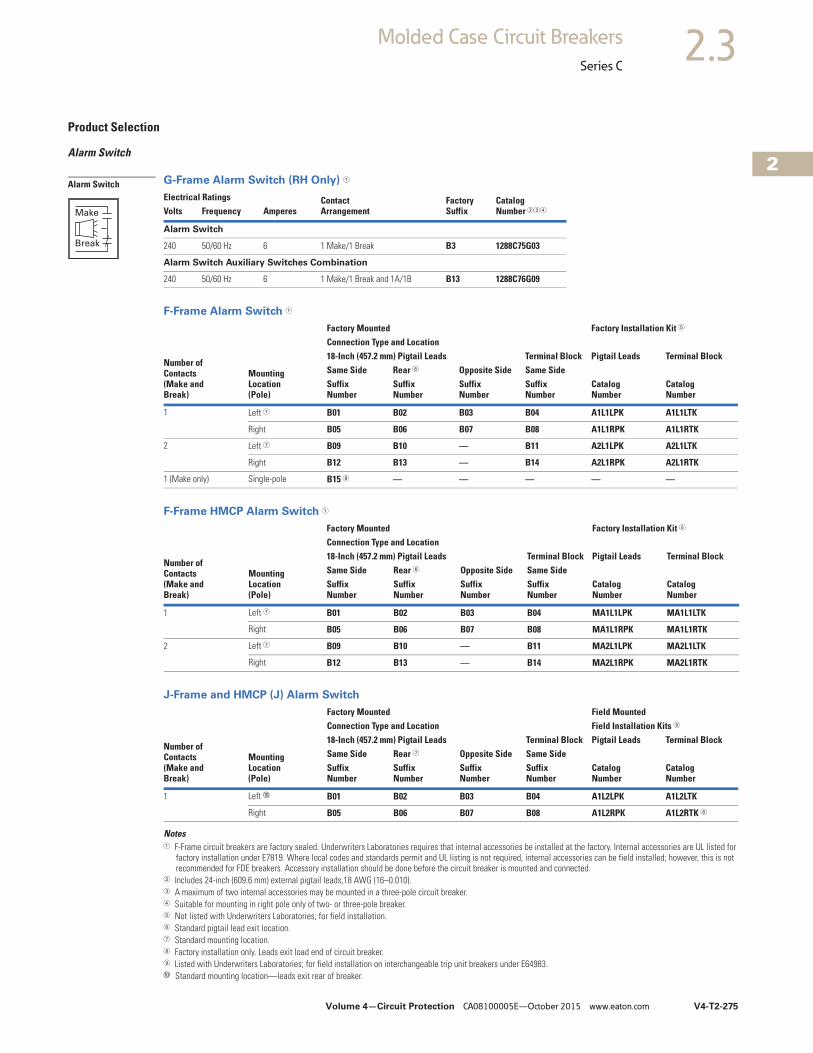
Volume 4—Circuit Protection CA08100005E—October 2015 www.eaton.com V4-T2-275
2
2
2
2
2
2
2
2
2
2
2
2
2
2
2
2
2
2
2
2
2
2
2
2
2
2
2
2
2
2
2.3Molded Case Circuit Breakers
Series C
Product Selection
Alarm Switch
G-Frame Alarm Switch (RH Only) 1
F-Frame Alarm Switch 1
F-Frame HMCP Alarm Switch 1
J-Frame and HMCP (J) Alarm Switch
Notes1 F-Frame circuit breakers are factory sealed. Underwriters Laboratories requires that internal accessories be installed at the factory. Internal accessories are UL listed for
factory installation under E7819. Where local codes and standards permit and UL listing is not required, internal accessories can be field installed; however, this is not recommended for FDE breakers. Accessory installation should be done before the circuit breaker is mounted and connected.
2 Includes 24-inch (609.6 mm) external pigtail leads,18 AWG (16–0.010).3 A maximum of two internal accessories may be mounted in a three-pole circuit breaker.4 Suitable for mounting in right pole only of two- or three-pole breaker.5 Not listed with Underwriters Laboratories; for field installation.6 Standard pigtail lead exit location.7 Standard mounting location.8 Factory installation only. Leads exit load end of circuit breaker.9 Listed with Underwriters Laboratories; for field installation on interchangeable trip unit breakers under E64983.j Standard mounting location—leads exit rear of breaker.
Electrical Ratings Contact Arrangement
FactorySuffix
CatalogNumber 234Volts Frequency Amperes
Alarm Switch
240 50/60 Hz 6 1 Make/1 Break B3 1288C75G03
Alarm Switch Auxiliary Switches Combination
240 50/60 Hz 6 1 Make/1 Break and 1A/1B B13 1288C76G09
Number ofContacts(Make andBreak)
MountingLocation(Pole)
Factory Mounted Factory Installation Kit 5
Connection Type and Location18-Inch (457.2 mm) Pigtail Leads Terminal Block Pigtail Leads Terminal BlockSame Side Rear 6 Opposite Side Same SideSuffixNumber
SuffixNumber
SuffixNumber
SuffixNumber
CatalogNumber
CatalogNumber
1 Left 7 B01 B02 B03 B04 A1L1LPK A1L1LTK
Right B05 B06 B07 B08 A1L1RPK A1L1RTK
2 Left 7 B09 B10 — B11 A2L1LPK A2L1LTK
Right B12 B13 — B14 A2L1RPK A2L1RTK
1 (Make only) Single-pole B15 8 — — — — —
Number ofContacts(Make andBreak)
MountingLocation(Pole)
Factory Mounted Factory Installation Kit 5
Connection Type and Location18-Inch (457.2 mm) Pigtail Leads Terminal Block Pigtail Leads Terminal BlockSame Side Rear 6 Opposite Side Same SideSuffixNumber
SuffixNumber
SuffixNumber
SuffixNumber
CatalogNumber
CatalogNumber
1 Left 7 B01 B02 B03 B04 MA1L1LPK MA1L1LTK
Right B05 B06 B07 B08 MA1L1RPK MA1L1RTK
2 Left 7 B09 B10 — B11 MA2L1LPK MA2L1LTK
Right B12 B13 — B14 MA2L1RPK MA2L1RTK
Number ofContacts(Make andBreak)
MountingLocation(Pole)
Factory Mounted Field MountedConnection Type and Location Field Installation Kits 9
18-Inch (457.2 mm) Pigtail Leads Terminal Block Pigtail Leads Terminal BlockSame Side Rear 7 Opposite Side Same SideSuffixNumber
SuffixNumber
SuffixNumber
SuffixNumber
CatalogNumber
CatalogNumber
1 Left j B01 B02 B03 B04 A1L2LPK A1L2LTK
Right B05 B06 B07 B08 A1L2RPK A1L2RTK 6
Alarm Switch
Make
Break
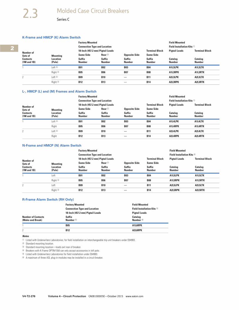
V4-T2-276 Volume 4—Circuit Protection CA08100005E—October 2015 www.eaton.com
2
2
2
2
2
2
2
2
2
2
2
2
2
2
2
2
2
2
2
2
2
2
2
2
2
2
2
2
2
2
2.3 Molded Case Circuit Breakers
Series C
K-Frame and HMCP (K) Alarm Switch
L-, HMCP (L) and (M) Frames and Alarm Switch
N-Frame and HMCP (N) Alarm Switch
R-Frame Alarm Switch (RH Only)
Notes1 Listed with Underwriters Laboratories; for field installation on interchangeable trip unit breakers under E64983.2 Standard mounting location.3 Standard mounting location—leads exit rear of breaker.4 Breakers with K-Frame OPTIM 550 can only accept accessories in left pole.5 Listed with Underwriters Laboratories for field installation under E64983.6 A maximum of three ASL plug-in modules may be installed in a circuit breaker.
Number ofSets ofContacts(1M and 1B)
MountingLocation(Pole)
Factory Mounted Field MountedConnection Type and Location Field Installation Kits 1
18-Inch (457.2 mm) Pigtail Leads Terminal Block Pigtail Leads Terminal BlockSame Side Rear 2 Opposite Side Same SideSuffixNumber
SuffixNumber
SuffixNumber
SuffixNumber
CatalogNumber
CatalogNumber
1 Left 3 B01 B02 B03 B04 A1L3LPK A1L3LTK
Right 4 B05 B06 B07 B08 A1L3RPK A1L3RTK
2 Left 3 B09 B10 — B11 A2L3LPK A2L3LTK
Right 4 B12 B13 — B14 A2L3RPK A2L3RTK
Number ofSets ofContacts(1M and 1B)
MountingLocation(Pole)
Factory Mounted Field MountedConnection Type and Location Field Installation Kits 1
18-Inch (457.2 mm) Pigtail Leads Terminal Block Pigtail Leads Terminal BlockSame Side Rear 2 Opposite Side Same SideSuffixNumber
SuffixNumber
SuffixNumber
SuffixNumber
CatalogNumber
CatalogNumber
1 Left 3 B01 B02 B03 B04 A1L4LPK A1L4LTK
Right B05 B06 B07 B08 A1L4RPK A1L4RTK
2 Left 3 B09 B10 — B11 A2L4LPK A2L4LTK
Right B12 B13 — B14 A2L4RPK A2L4RTK
Number ofSets ofContacts(1M and 1B)
MountingLocation(Pole)
Factory Mounted Field MountedConnection Type and Location Field Installation Kits 5
18-Inch (457.2 mm) Pigtail Leads Terminal Block Pigtail Leads Terminal BlockSame Side Rear 2 Opposite Side Same SideSuffixNumber
SuffixNumber
SuffixNumber
SuffixNumber
CatalogNumber
CatalogNumber
1 Left B01 B02 B03 B04 A1L5LPK A1L5LTK
Right 3 B05 B06 B07 B08 A1L5RPK A1L5RTK
2 Left B09 B10 — B11 A2L5LPK A2L5LTK
Right 3 B12 B13 — B14 A2L5RPK A2L5RTK
Factory Mounted Field MountedConnection Type and Location Field Installation Kits 5
18-Inch (457.2 mm) Pigtail Leads Pigtail LeadsNumber of Contacts(Make and Break)
SuffixNumber 6
CatalogNumber 6
1 B05 A1L6RPK
2 B12 A2L6RPK
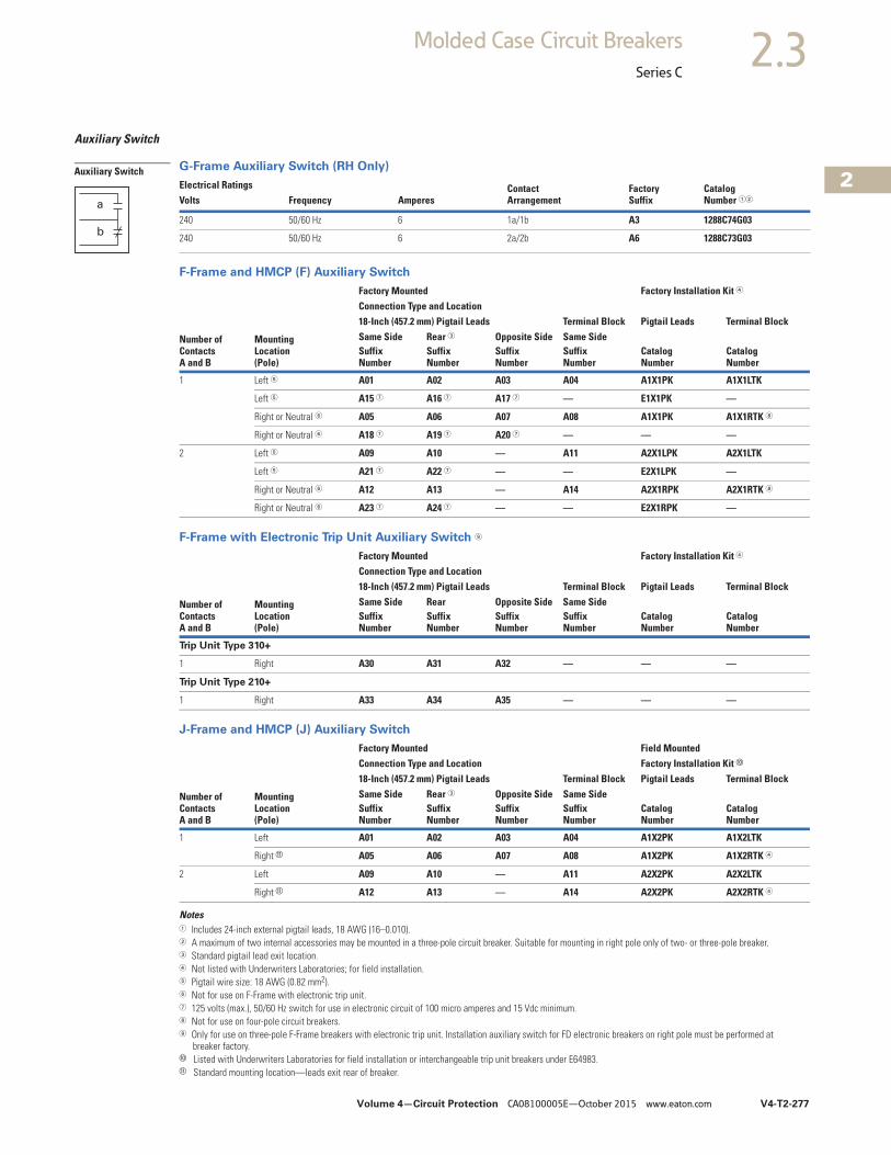
Volume 4—Circuit Protection CA08100005E—October 2015 www.eaton.com V4-T2-277
2
2
2
2
2
2
2
2
2
2
2
2
2
2
2
2
2
2
2
2
2
2
2
2
2
2
2
2
2
2
2.3Molded Case Circuit Breakers
Series C
Auxiliary Switch
G-Frame Auxiliary Switch (RH Only)
F-Frame and HMCP (F) Auxiliary Switch
F-Frame with Electronic Trip Unit Auxiliary Switch 9
J-Frame and HMCP (J) Auxiliary Switch
Notes1 Includes 24-inch external pigtail leads, 18 AWG (16–0.010).2 A maximum of two internal accessories may be mounted in a three-pole circuit breaker. Suitable for mounting in right pole only of two- or three-pole breaker.3 Standard pigtail lead exit location.4 Not listed with Underwriters Laboratories; for field installation.5 Pigtail wire size: 18 AWG (0.82 mm2).6 Not for use on F-Frame with electronic trip unit.7 125 volts (max.), 50/60 Hz switch for use in electronic circuit of 100 micro amperes and 15 Vdc minimum.8 Not for use on four-pole circuit breakers.9 Only for use on three-pole F-Frame breakers with electronic trip unit. Installation auxiliary switch for FD electronic breakers on right pole must be performed at
breaker factory.j Listed with Underwriters Laboratories for field installation or interchangeable trip unit breakers under E64983.k Standard mounting location—leads exit rear of breaker.
Electrical Ratings Contact Arrangement
FactorySuffix
CatalogNumber 12Volts Frequency Amperes
240 50/60 Hz 6 1a/1b A3 1288C74G03
240 50/60 Hz 6 2a/2b A6 1288C73G03
Number ofContactsA and B
MountingLocation(Pole)
Factory Mounted Factory Installation Kit 4
Connection Type and Location18-Inch (457.2 mm) Pigtail Leads Terminal Block Pigtail Leads Terminal BlockSame Side Rear 3 Opposite Side Same SideSuffixNumber
SuffixNumber
SuffixNumber
SuffixNumber
CatalogNumber
CatalogNumber
1 Left 5 A01 A02 A03 A04 A1X1PK A1X1LTK
Left 5 A15 7 A16 7 A17 7 — E1X1PK —
Right or Neutral 6 A05 A06 A07 A08 A1X1PK A1X1RTK 8
Right or Neutral 6 A18 7 A19 7 A20 7 — — —
2 Left 5 A09 A10 — A11 A2X1LPK A2X1LTK
Left 5 A21 7 A22 7 — — E2X1LPK —
Right or Neutral 6 A12 A13 — A14 A2X1RPK A2X1RTK 8
Right or Neutral 6 A23 7 A24 7 — — E2X1RPK —
Number ofContactsA and B
MountingLocation(Pole)
Factory Mounted Factory Installation Kit 4
Connection Type and Location18-Inch (457.2 mm) Pigtail Leads Terminal Block Pigtail Leads Terminal BlockSame Side Rear Opposite Side Same SideSuffixNumber
SuffixNumber
SuffixNumber
SuffixNumber
CatalogNumber
CatalogNumber
Trip Unit Type 310+
1 Right A30 A31 A32 — — —
Trip Unit Type 210+
1 Right A33 A34 A35 — — —
Number ofContactsA and B
MountingLocation(Pole)
Factory Mounted Field MountedConnection Type and Location Factory Installation Kit j
18-Inch (457.2 mm) Pigtail Leads Terminal Block Pigtail Leads Terminal BlockSame Side Rear 3 Opposite Side Same SideSuffixNumber
SuffixNumber
SuffixNumber
SuffixNumber
CatalogNumber
CatalogNumber
1 Left A01 A02 A03 A04 A1X2PK A1X2LTK
Right k A05 A06 A07 A08 A1X2PK A1X2RTK 4
2 Left A09 A10 — A11 A2X2PK A2X2LTK
Right k A12 A13 — A14 A2X2PK A2X2RTK 4
Auxiliary Switch
a
b
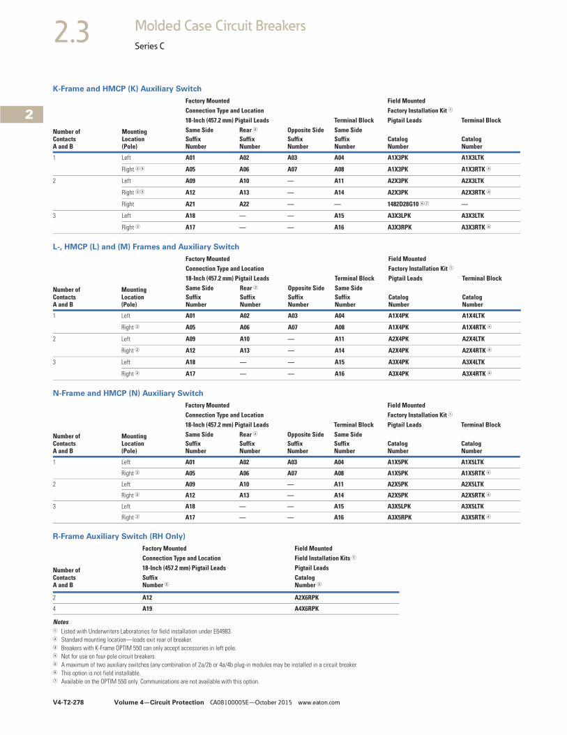
V4-T2-278 Volume 4—Circuit Protection CA08100005E—October 2015 www.eaton.com
2
2
2
2
2
2
2
2
2
2
2
2
2
2
2
2
2
2
2
2
2
2
2
2
2
2
2
2
2
2
2.3 Molded Case Circuit Breakers
Series C
K-Frame and HMCP (K) Auxiliary Switch
L-, HMCP (L) and (M) Frames and Auxiliary Switch
N-Frame and HMCP (N) Auxiliary Switch
R-Frame Auxiliary Switch (RH Only)
Notes1 Listed with Underwriters Laboratories for field installation under E64983.2 Standard mounting location—leads exit rear of breaker.3 Breakers with K-Frame OPTIM 550 can only accept accessories in left pole.4 Not for use on four-pole circuit breakers.5 A maximum of two auxiliary switches (any combination of 2a/2b or 4a/4b plug-in modules may be installed in a circuit breaker.6 This option is not field installable.7 Available on the OPTIM 550 only. Communications are not available with this option.
Number ofContactsA and B
MountingLocation(Pole)
Factory Mounted Field MountedConnection Type and Location Factory Installation Kit 1
18-Inch (457.2 mm) Pigtail Leads Terminal Block Pigtail Leads Terminal BlockSame Side Rear 2 Opposite Side Same SideSuffixNumber
SuffixNumber
SuffixNumber
SuffixNumber
CatalogNumber
CatalogNumber
1 Left A01 A02 A03 A04 A1X3PK A1X3LTK
Right 23 A05 A06 A07 A08 A1X3PK A1X3RTK 4
2 Left A09 A10 — A11 A2X3PK A2X3LTK
Right 23 A12 A13 — A14 A2X3PK A2X3RTK 4
Right A21 A22 — — 1482D28G10 67 —
3 Left A18 — — A15 A3X3LPK A3X3LTK
Right 3 A17 — — A16 A3X3RPK A3X3RTK 4
Number ofContactsA and B
MountingLocation(Pole)
Factory Mounted Field MountedConnection Type and Location Factory Installation Kit 1
18-Inch (457.2 mm) Pigtail Leads Terminal Block Pigtail Leads Terminal BlockSame Side Rear 2 Opposite Side Same SideSuffixNumber
SuffixNumber
SuffixNumber
SuffixNumber
CatalogNumber
CatalogNumber
1 Left A01 A02 A03 A04 A1X4PK A1X4LTK
Right 2 A05 A06 A07 A08 A1X4PK A1X4RTK 4
2 Left A09 A10 — A11 A2X4PK A2X4LTK
Right 2 A12 A13 — A14 A2X4PK A2X4RTK 4
3 Left A18 — — A15 A3X4PK A3X4LTK
Right 2 A17 — — A16 A3X4PK A3X4RTK 4
Number ofContactsA and B
MountingLocation(Pole)
Factory Mounted Field MountedConnection Type and Location Factory Installation Kit 1
18-Inch (457.2 mm) Pigtail Leads Terminal Block Pigtail Leads Terminal BlockSame Side Rear 2 Opposite Side Same SideSuffixNumber
SuffixNumber
SuffixNumber
SuffixNumber
CatalogNumber
CatalogNumber
1 Left A01 A02 A03 A04 A1X5PK A1X5LTK
Right 2 A05 A06 A07 A08 A1X5PK A1X5RTK 4
2 Left A09 A10 — A11 A2X5PK A2X5LTK
Right 2 A12 A13 — A14 A2X5PK A2X5RTK 4
3 Left A18 — — A15 A3X5LPK A3X5LTK
Right 2 A17 — — A16 A3X5RPK A3X5RTK 4
Number of ContactsA and B
Factory Mounted Field MountedConnection Type and Location Field Installation Kits 1
18-Inch (457.2 mm) Pigtail Leads Pigtail LeadsSuffixNumber 5
CatalogNumber 5
2 A12 A2X6RPK
4 A19 A4X6RPK
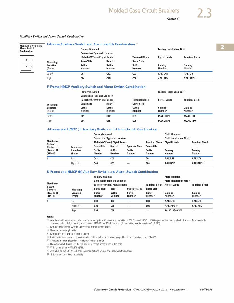
Volume 4—Circuit Protection CA08100005E—October 2015 www.eaton.com V4-T2-279
2
2
2
2
2
2
2
2
2
2
2
2
2
2
2
2
2
2
2
2
2
2
2
2
2
2
2
2
2
2
2.3Molded Case Circuit Breakers
Series C
Auxiliary Switch and Alarm Switch Combination
F-Frame Auxiliary Switch and Alarm Switch Combination 1
F-Frame HMCP Auxiliary Switch and Alarm Switch Combination
J-Frame and HMCP (J) Auxiliary Switch and Alarm Switch Combination
K-Frame and HMCP (K) Auxiliary Switch and Alarm Switch Combination
Notes1 Auxiliary switch and alarm switch combination options (Cxx) are not available on FDE 310+ with LSG or LSIG trip units due to exit wire limitations. To obtain both
features, order a left mounting alarm switch (B01-B04 or B09-B11), and right mounting auxiliary switch (A30-A32).2 Not listed with Underwriters Laboratories for field installation.3 Standard mounting location.4 Not for use on four-pole circuit breakers5 Listed with Underwriters Laboratories for field installation of interchangeable trip unit breakers under E64983.6 Standard mounting location—leads exit rear of breaker.7 Breakers with K-Frame OPTIM 550 can only accept accessories in left pole.8 Will not install on OPTIM Trip (RH).9 Available on the OPTIM 550 only. Communications are not available with this option.j This option is not field installable.
MountingLocation(Pole)
Factory Mounted Factory Installation Kit 2
Connection Type and Location18-Inch (457 mm) Pigtail Leads Terminal Block Pigtail Leads Terminal BlockSame Side Rear 3 Same SideSuffixNumber
SuffixNumber
SuffixNumber
CatalogNumber
CatalogNumber
Left 3 C01 C02 C03 AAL1LPK AAL1LTK
Right C04 C05 C06 AAL1RPK AAL1RTK 4
MountingLocation(Pole)
Factory Mounted Factory Installation Kit 2
Connection Type and Location18-Inch (457 mm) Pigtail Leads Terminal Block Pigtail Leads Terminal BlockSame Side Rear 3 Same SideSuffixNumber
SuffixNumber
SuffixNumber
CatalogNumber
CatalogNumber
Left 4 C01 C02 C03 MAAL1LPK MAAL1LTK
Right C04 C05 C06 MAAL1RPK MAAL1RPK
Number ofSets ofContacts(1A and 1B)(1M–1B)
MountingLocation(Pole)
Factory Mounted Field MountedConnection Type and Location Field Installation Kits 5
18-Inch (457 mm) Pigtail Leads Terminal Block Pigtail Leads Terminal BlockSame Side Rear 6 Opposite Side Same SideSuffixNumber
SuffixNumber
SuffixNumber
SuffixNumber
CatalogNumber
CatalogNumber
1 Left C01 C02 — C03 AAL2LPK AAL2LTK
Right 4 C04 C05 — C06 AAL2RPK AAL2RTK 4
Number ofSets ofContacts(1A and 1B)(1M–1B)
MountingLocation(Pole)
Factory Mounted Field MountedConnection Type and Location Field Installation Kits 5
18-Inch (457 mm) Pigtail Leads Terminal Block Pigtail Leads Terminal BlockSame Side Rear 6 Opposite Side Same SideSuffixNumber
SuffixNumber
SuffixNumber
SuffixNumber
CatalogNumber
CatalogNumber
1 Left C01 C02 — C03 AAL3LPK AAL3LTK
Right 67 C04 C05 — C06 AAL3RPK 8 AAL3RTK
Right C07 C08 — — 1482D28G09 9j —
Auxiliary Switch and Alarm Switch Combination
a
b
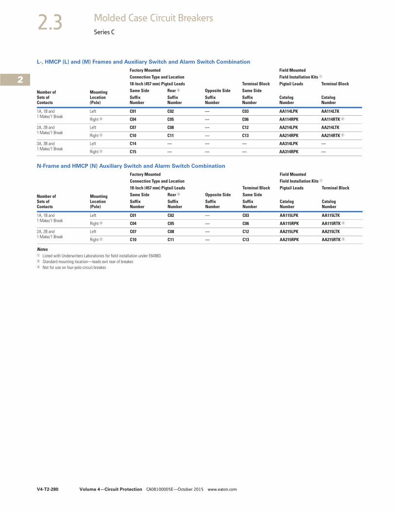
V4-T2-280 Volume 4—Circuit Protection CA08100005E—October 2015 www.eaton.com
2
2
2
2
2
2
2
2
2
2
2
2
2
2
2
2
2
2
2
2
2
2
2
2
2
2
2
2
2
2
2.3 Molded Case Circuit Breakers
Series C
L-, HMCP (L) and (M) Frames and Auxiliary Switch and Alarm Switch Combination
N-Frame and HMCP (N) Auxiliary Switch and Alarm Switch Combination
Notes1 Listed with Underwriters Laboratories for field installation under E64983.2 Standard mounting location—leads exit rear of breaker.3 Not for use on four-pole circuit breaker.
Number ofSets ofContacts
MountingLocation(Pole)
Factory Mounted Field MountedConnection Type and Location Field Installation Kits 1
18-Inch (457 mm) Pigtail Leads Terminal Block Pigtail Leads Terminal BlockSame Side Rear 2 Opposite Side Same SideSuffixNumber
SuffixNumber
SuffixNumber
SuffixNumber
CatalogNumber
CatalogNumber
1A, 1B and1 Make/1 Break
Left C01 C02 — C03 AA114LPK AA114LTK
Right 2 C04 C05 — C06 AA114RPK AA114RTK 3
2A, 2B and1 Make/1 Break
Left C07 C08 — C12 AA214LPK AA214LTK
Right 2 C10 C11 — C13 AA214RPK AA214RTK 3
3A, 3B and1 Make/1 Break
Left C14 — — — AA314LPK —
Right 2 C15 — — — AA314RPK —
Number ofSets ofContacts
MountingLocation(Pole)
Factory Mounted Field MountedConnection Type and Location Field Installation Kits 1
18-Inch (457 mm) Pigtail Leads Terminal Block Pigtail Leads Terminal BlockSame Side Rear 2 Opposite Side Same SideSuffixNumber
SuffixNumber
SuffixNumber
SuffixNumber
CatalogNumber
CatalogNumber
1A, 1B and1 Make/1 Break
Left C01 C02 — C03 AA115LPK AA115LTK
Right 2 C04 C05 — C06 AA115RPK AA115RTK 3
2A, 2B and1 Make/1 Break
Left C07 C08 — C12 AA215LPK AA215LTK
Right 2 C10 C11 — C13 AA215RPK AA215RTK 3
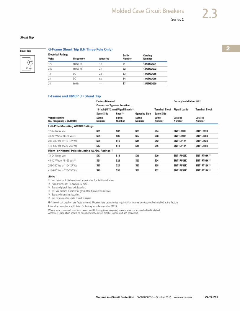
Volume 4—Circuit Protection CA08100005E—October 2015 www.eaton.com V4-T2-281
2
2
2
2
2
2
2
2
2
2
2
2
2
2
2
2
2
2
2
2
2
2
2
2
2
2
2
2
2
2
2.3Molded Case Circuit Breakers
Series C
Shunt Trip
G-Frame Shunt Trip (LH Three-Pole Only)
F-Frame and HMCP (F) Shunt Trip
Notes1 Not listed with Underwriters Laboratories, for field installation.2 Pigtail wire size: 18 AWG (0.82 mm2).3 Standard pigtail lead exit location.4 120 Vac marked suitable for ground fault protection devices.5 Standard mounting location.6 Not for use on four-pole circuit breakers.
G-Frame circuit breakers are factory sealed. Underwriters Laboratories requires that internal accessories be installed at the factory.Internal accessories are UL listed for factory installation under E7819.Where local codes and standards permit and UL listing is not required, internal accessories can be field installed. Accessory installation should be done before the circuit breaker is mounted and connected.
Electrical Ratings SuffixNumber
CatalogNumberVolts Frequency Amperes
120 50/60 Hz 1.1 S1 1373D62G01
240 50/60 Hz 2.1 S2 1373D62G02
12 DC 2.8 S3 1373D62G15
24 DC 5.7 S4 1373D62G16
24 60 Hz — S7 1373D62G20
Factory Mounted Factory Installation Kit 1
Connection Type and Location18-Inch (457.2 mm) Pigtail Leads 2 Terminal Block Pigtail Leads Terminal BlockSame Side Rear 3 Opposite Side Same Side
Voltage Rating (AC Frequency = 50/60 Hz)
SuffixNumber
SuffixNumber
SuffixNumber
SuffixNumber
CatalogNumber
CatalogNumber
Left-Pole Mounting AC/DC Ratings
12–24 Vac or Vdc S01 S02 S03 S04 SNT1LP03K SNT1LT03K
48–127 Vac or 48–60 Vdc 4 S05 S06 S07 S08 SNT1LP08K SNT1LT08K
208–380 Vac or 110–127 Vdc S09 S10 S11 S12 SNT1LP12K SNT1LT12K
415–600 Vac or 220–250 Vdc S13 S14 S15 S16 SNT1LP18K SNT1LT18K
Right- or Neutral-Pole Mounting AC/DC Ratings 5
12–24 Vac or Vdc S17 S18 S19 S20 SNT1RP03K SNT1RT03K 6
48–127 Vac or 48–60 Vdc 4 S21 S22 S23 S24 SNT1RP08K SNT1RT08K 6
208–380 Vac or 110–127 Vdc S25 S26 S27 S28 SNT1RP12K SNT1RT12K 6
415–600 Vac or 220–250 Vdc S29 S30 S31 S32 SNT1RP18K SNT1RT18K 6
Shunt Trip
ST
a
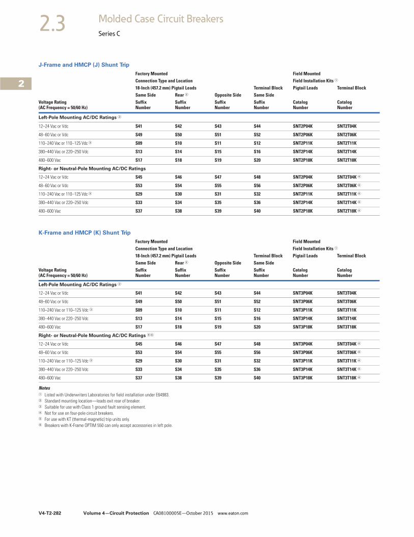
V4-T2-282 Volume 4—Circuit Protection CA08100005E—October 2015 www.eaton.com
2
2
2
2
2
2
2
2
2
2
2
2
2
2
2
2
2
2
2
2
2
2
2
2
2
2
2
2
2
2
2.3 Molded Case Circuit Breakers
Series C
J-Frame and HMCP (J) Shunt Trip
K-Frame and HMCP (K) Shunt Trip
Notes1 Listed with Underwriters Laboratories for field installation under E64983.2 Standard mounting location—leads exit rear of breaker.3 Suitable for use with Class 1 ground fault sensing element.4 Not for use on four-pole circuit breakers.5 For use with KT (thermal-magnetic) trip units only.6 Breakers with K-Frame OPTIM 550 can only accept accessories in left pole.
Factory Mounted Field MountedConnection Type and Location Field Installation Kits 1
18-Inch (457.2 mm) Pigtail Leads Terminal Block Pigtail Leads Terminal BlockSame Side Rear 2 Opposite Side Same Side
Voltage Rating(AC Frequency = 50/60 Hz)
SuffixNumber
SuffixNumber
SuffixNumber
SuffixNumber
CatalogNumber
CatalogNumber
Left-Pole Mounting AC/DC Ratings 2
12–24 Vac or Vdc S41 S42 S43 S44 SNT2P04K SNT2T04K
48–60 Vac or Vdc S49 S50 S51 S52 SNT2P06K SNT2T06K
110–240 Vac or 110–125 Vdc 3 S09 S10 S11 S12 SNT2P11K SNT2T11K
380–440 Vac or 220–250 Vdc S13 S14 S15 S16 SNT2P14K SNT2T14K
480–600 Vac S17 S18 S19 S20 SNT2P18K SNT2T18K
Right- or Neutral-Pole Mounting AC/DC Ratings
12–24 Vac or Vdc S45 S46 S47 S48 SNT2P04K SNT2T04K 4
48–60 Vac or Vdc S53 S54 S55 S56 SNT2P06K SNT2T06K 4
110–240 Vac or 110–125 Vdc 3 S29 S30 S31 S32 SNT2P11K SNT2T11K 4
380–440 Vac or 220–250 Vdc S33 S34 S35 S36 SNT2P14K SNT2T14K 4
480–600 Vac S37 S38 S39 S40 SNT2P18K SNT2T18K 4
Factory Mounted Field MountedConnection Type and Location Field Installation Kits 1
18-Inch (457.2 mm) Pigtail Leads Terminal Block Pigtail Leads Terminal BlockSame Side Rear 2 Opposite Side Same Side
Voltage Rating(AC Frequency = 50/60 Hz)
SuffixNumber
SuffixNumber
SuffixNumber
SuffixNumber
CatalogNumber
CatalogNumber
Left-Pole Mounting AC/DC Ratings 2
12–24 Vac or Vdc S41 S42 S43 S44 SNT3P04K SNT3T04K
48–60 Vac or Vdc S49 S50 S51 S52 SNT3P06K SNT3T06K
110–240 Vac or 110–125 Vdc 3 S09 S10 S11 S12 SNT3P11K SNT3T11K
380–440 Vac or 220–250 Vdc S13 S14 S15 S16 SNT3P14K SNT3T14K
480–600 Vac S17 S18 S19 S20 SNT3P18K SNT3T18K
Right- or Neutral-Pole Mounting AC/DC Ratings 56
12–24 Vac or Vdc S45 S46 S47 S48 SNT3P04K SNT3T04K 4
48–60 Vac or Vdc S53 S54 S55 S56 SNT3P06K SNT3T06K 4
110–240 Vac or 110–125 Vdc 3 S29 S30 S31 S32 SNT3P11K SNT3T11K 4
380–440 Vac or 220–250 Vdc S33 S34 S35 S36 SNT3P14K SNT3T14K 4
480–600 Vac S37 S38 S39 S40 SNT3P18K SNT3T18K 4
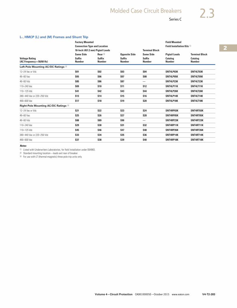
Volume 4—Circuit Protection CA08100005E—October 2015 www.eaton.com V4-T2-283
2
2
2
2
2
2
2
2
2
2
2
2
2
2
2
2
2
2
2
2
2
2
2
2
2
2
2
2
2
2
2.3Molded Case Circuit Breakers
Series C
L-, HMCP (L) and (M) Frames and Shunt Trip
Notes1 Listed with Underwriters Laboratories, for field installation under E64983.2 Standard mounting location—leads exit rear of breaker.3 For use with LT (thermal-magnetic) three-pole trip units only.
Voltage Rating(AC Frequency = 50/60 Hz)
Factory Mounted Field MountedConnection Type and Location Field Installation Kits 1
18-Inch (457.2 mm) Pigtail Leads Terminal BlockPigtail Leads Terminal BlockSame Side Rear 2 Opposite Side Same Side
SuffixNumber
SuffixNumber
SuffixNumber
SuffixNumber
CatalogNumber
CatalogNumber
Left-Pole Mounting AC/DC Ratings 2
12–24 Vac or Vdc S01 S02 S03 S04 SNT4LP03K SNT4LT03K
48–60 Vac S05 S06 S07 S08 SNT4LP05K SNT4LT05K
48–60 Vdc S85 S86 S87 — SNT4LP23K SNT4LT23K
110–240 Vac S09 S10 S11 S12 SNT4LP11K SNT4LT11K
110–125 Vdc S41 S42 S43 S44 SNT4LP26K SNT4LT26K
380–440 Vac or 220–250 Vdc S13 S14 S15 S16 SNT4LP14K SNT4LT14K
480–600 Vac S17 S18 S19 S20 SNT4LP18K SNT4LT18K
Right-Pole Mounting AC/DC Ratings 3
12–24 Vac or Vdc S21 S22 S23 S24 SNT4RP03K SNT4RT03K
48–60 Vac S25 S26 S27 S28 SNT4RP05K SNT4RT05K
48–60 Vdc S88 S89 S90 — SNT4RP23K SNT4RT23K
110–240 Vac S29 S30 S31 S32 SNT4RP11K SNT4RT11K
110–125 Vdc S45 S46 S47 S48 SNT4RP26K SNT4RT26K
380–440 Vac or 220–250 Vdc S33 S34 S35 S36 SNT4RP14K SNT4RT14K
480–600 Vac S37 S38 S39 S40 SNT4RP18K SNT4RT18K
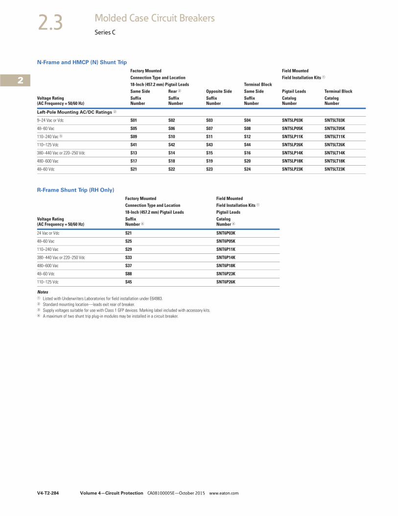
V4-T2-284 Volume 4—Circuit Protection CA08100005E—October 2015 www.eaton.com
2
2
2
2
2
2
2
2
2
2
2
2
2
2
2
2
2
2
2
2
2
2
2
2
2
2
2
2
2
2
2.3 Molded Case Circuit Breakers
Series C
N-Frame and HMCP (N) Shunt Trip
R-Frame Shunt Trip (RH Only)
Notes1 Listed with Underwriters Laboratories for field installation under E64983.2 Standard mounting location—leads exit rear of breaker.3 Supply voltages suitable for use with Class 1 GFP devices. Marking label included with accessory kits.4 A maximum of two shunt trip plug-in modules may be installed in a circuit breaker.
Voltage Rating (AC Frequency = 50/60 Hz)
Factory Mounted Field MountedConnection Type and Location Field Installation Kits 1
18-Inch (457.2 mm) Pigtail Leads Terminal BlockPigtail Leads Terminal BlockSame Side Rear 2 Opposite Side Same Side
SuffixNumber
SuffixNumber
SuffixNumber
SuffixNumber
CatalogNumber
CatalogNumber
Left-Pole Mounting AC/DC Ratings 2
9–24 Vac or Vdc S01 S02 S03 S04 SNT5LP03K SNT5LT03K
48–60 Vac S05 S06 S07 S08 SNT5LP05K SNT5LT05K
110–240 Vac 3 S09 S10 S11 S12 SNT5LP11K SNT5LT11K
110–125 Vdc S41 S42 S43 S44 SNT5LP26K SNT5LT26K
380–440 Vac or 220–250 Vdc S13 S14 S15 S16 SNT5LP14K SNT5LT14K
480–600 Vac S17 S18 S19 S20 SNT5LP18K SNT5LT18K
48–60 Vdc S21 S22 S23 S24 SNT5LP23K SNT5LT23K
Voltage Rating (AC Frequency = 50/60 Hz)
Factory Mounted Field MountedConnection Type and Location Field Installation Kits 1
18-Inch (457.2 mm) Pigtail Leads Pigtail LeadsSuffixNumber 4
CatalogNumber 4
24 Vac or Vdc S21 SNT6P03K
48–60 Vac S25 SNT6P05K
110–240 Vac S29 SNT6P11K
380–440 Vac or 220–250 Vdc S33 SNT6P14K
480–600 Vac S37 SNT6P18K
48–60 Vdc S88 SNT6P23K
110–125 Vdc S45 SNT6P26K

Volume 4—Circuit Protection CA08100005E—October 2015 www.eaton.com V4-T2-285
2
2
2
2
2
2
2
2
2
2
2
2
2
2
2
2
2
2
2
2
2
2
2
2
2
2
2
2
2
2
2.3Molded Case Circuit Breakers
Series C
Low Energy Shunt TripOrdering Information
Select shunt trip catalog number for the voltage within the indicated voltage range. Shunt trip coils are designed to be applied at specific AC or DC voltages within the voltage range shown. Electrical ratings are also shown on applicable circuit breaker accessory nameplates.
F-, J-, K-, L-, M-, N- and R-Frames and HMCPs Low Energy Shunt Trip 1
Notes1 Cutoff provisions required in control circuit.2 Listed with Underwriters Laboratories for field installation under E64983.3 Standard mounting location—leads exit rear of breaker.4 For F-Frame HMCP, add an “M” to beginning of catalog number. Field Installation Kit referenced for factory use only,
not UL listed for field installation.5 For use with thermal-magnetic trip units only.6 Breakers with K-Frame OPTIM 550 can only accept accessories in left pole.
MountingPositions(Pole)
Factory Mounted Field MountedConnection Type and Location Field Installation Kits 2
18-Inch (457.2 mm) Pigtail Leads Terminal Block
Same Side Rear 3Opposite Side Same Side Pigtail Leads Terminal Block
SuffixNumber
SuffixNumber
SuffixNumber
SuffixNumber
CatalogNumber
CatalogNumber
F-Frame
Left NO1 NO2 NO3 NO4 LST1LPK 4 LST1LTK 4
Right 3 NO5 NO6 NO7 NO8 LST1RPK 4 LST1RTK 4
J-Frame
Left NO1 NO2 NO3 — LST2LPK —
Right 3 NO5 NO6 NO7 — LST2RPK —
K-Frame
Left 3 NO1 NO2 NO3 — LST3LPK —
Right 56 NO5 NO6 NO7 — LST3RPK —
L- and M-Frames
Left NO1 NO2 NO3 — LST4LPK —
Right NO5 NO6 NO7 — LST4RPK —
N-Frame
Left 3 NO1 NO2 NO3 — LST5LPK —
R-Frame
Right NO1 — — — LST6RPK —
Low Energy Shunt Trip
UV
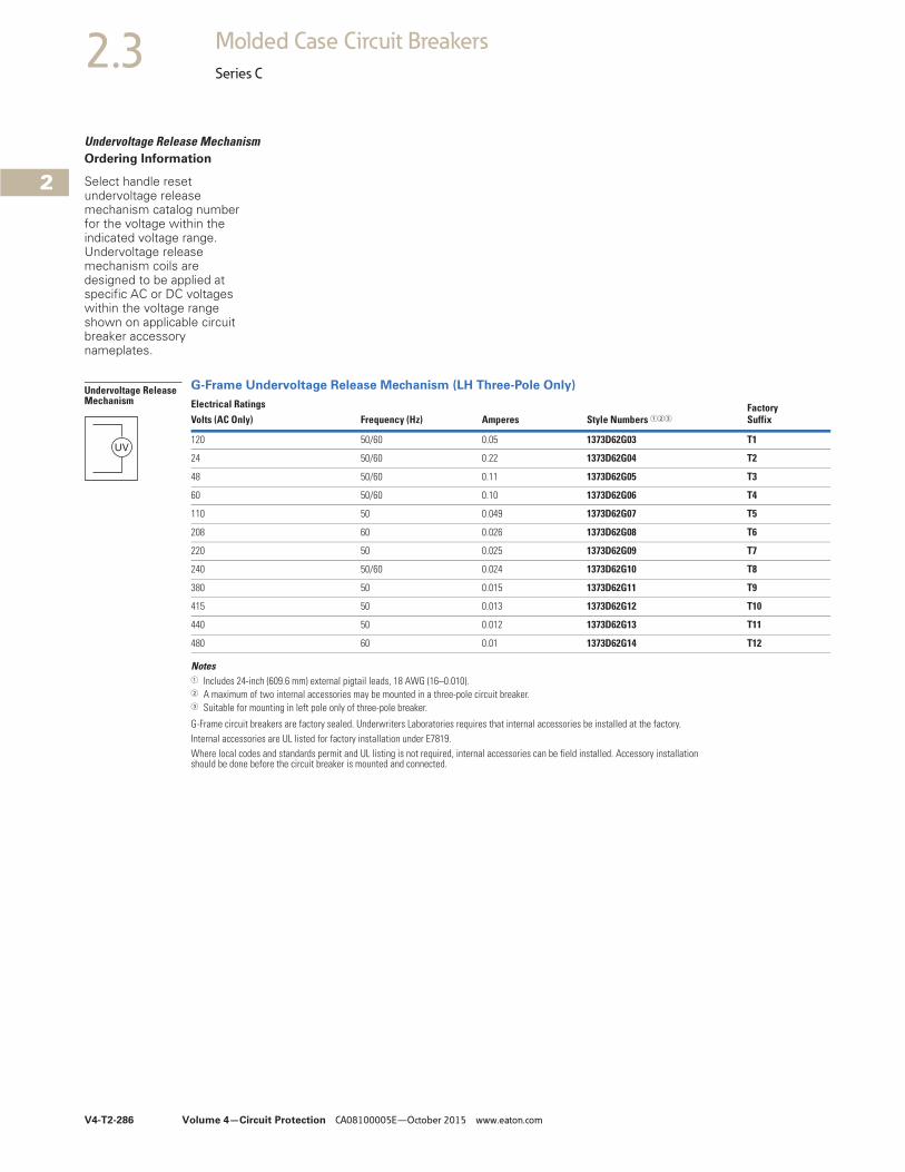
V4-T2-286 Volume 4—Circuit Protection CA08100005E—October 2015 www.eaton.com
2
2
2
2
2
2
2
2
2
2
2
2
2
2
2
2
2
2
2
2
2
2
2
2
2
2
2
2
2
2
2.3 Molded Case Circuit Breakers
Series C
Undervoltage Release MechanismOrdering Information
Select handle reset undervoltage release mechanism catalog number for the voltage within the indicated voltage range. Undervoltage release mechanism coils are designed to be applied at specific AC or DC voltages within the voltage range shown on applicable circuit breaker accessory nameplates.
G-Frame Undervoltage Release Mechanism (LH Three-Pole Only)
Notes1 Includes 24-inch (609.6 mm) external pigtail leads, 18 AWG (16–0.010).2 A maximum of two internal accessories may be mounted in a three-pole circuit breaker.3 Suitable for mounting in left pole only of three-pole breaker.
G-Frame circuit breakers are factory sealed. Underwriters Laboratories requires that internal accessories be installed at the factory.Internal accessories are UL listed for factory installation under E7819.Where local codes and standards permit and UL listing is not required, internal accessories can be field installed. Accessory installation should be done before the circuit breaker is mounted and connected.
Electrical RatingsStyle Numbers 123
FactorySuffixVolts (AC Only) Frequency (Hz) Amperes
120 50/60 0.05 1373D62G03 T1
24 50/60 0.22 1373D62G04 T2
48 50/60 0.11 1373D62G05 T3
60 50/60 0.10 1373D62G06 T4
110 50 0.049 1373D62G07 T5
208 60 0.026 1373D62G08 T6
220 50 0.025 1373D62G09 T7
240 50/60 0.024 1373D62G10 T8
380 50 0.015 1373D62G11 T9
415 50 0.013 1373D62G12 T10
440 50 0.012 1373D62G13 T11
480 60 0.01 1373D62G14 T12
Undervoltage Release Mechanism
UV
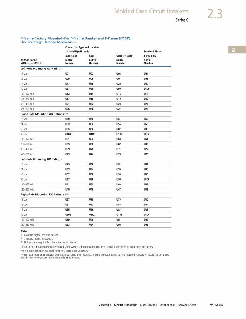
Volume 4—Circuit Protection CA08100005E—October 2015 www.eaton.com V4-T2-287
2
2
2
2
2
2
2
2
2
2
2
2
2
2
2
2
2
2
2
2
2
2
2
2
2
2
2
2
2
2
2.3Molded Case Circuit Breakers
Series C
F-Frame Factory Mounted (For F-Frame Breaker and F-Frame HMCP) Undervoltage Release Mechanism
Notes1 Standard pigtail lead exit location.2 Standard mounting location.3 Not for use on right pole of four-pole circuit breaker.
F-Frame circuit breakers are factory sealed. Underwriters Laboratories requires that internal accessories be installed at the factory.Internal accessories are UL listed for factory installation under E7819.Where local codes and standards permit and UL listing is not required, internal accessories can be field installed. Accessory installation should be done before the circuit breaker is mounted and connected.
Voltage Rating(AC Freq. = 50/60 Hz)
Connection Type and Location18-Inch Pigtail Leads Terminal BlockSame Side Rear 1 Opposite Side Same SideSuffixNumber
SuffixNumber
SuffixNumber
SuffixNumber
Left-Pole Mounting AC Ratings
12 Vac U01 U02 U03 U04
24 Vac U05 U06 U07 U08
48 Vac U37 U38 U39 U40
60 Vac U97 U98 U99 U100
110–127 Vac U13 U14 U15 U16
208–240 Vac U17 U18 U19 U20
380–480 Vac U21 U22 U23 U24
525–600 Vac U25 U26 U27 U28
Right-Pole Mounting AC Ratings 23
12 Vac U49 U50 U51 U52
24 Vac U53 U54 U55 U56
48 Vac U85 U86 U87 U88
60 Vac U101 U102 U103 U104
110–127 Vac U61 U62 U63 U64
208–240 Vac U65 U66 U67 U68
380–480 Vac U69 U70 U71 U72
525–600 Vac U73 U74 U75 U76
Left-Pole Mounting DC Ratings
12 Vdc U29 U30 U31 U32
24 Vdc U33 U34 U35 U36
48 Vdc U37 U38 U39 U40
60 Vdc U97 U98 U99 U100
110–127 Vdc U41 U42 U43 U44
220–250 Vdc U45 U46 U47 U48
Right-Pole Mounting DC Ratings 23
12 Vdc U77 U78 U79 U80
24 Vdc U81 U82 U83 U84
48 Vdc U85 U86 U87 U88
60 Vdc U101 U102 U103 U104
110–127 Vdc U89 U90 U91 U92
220–250 Vdc U93 U94 U95 U96
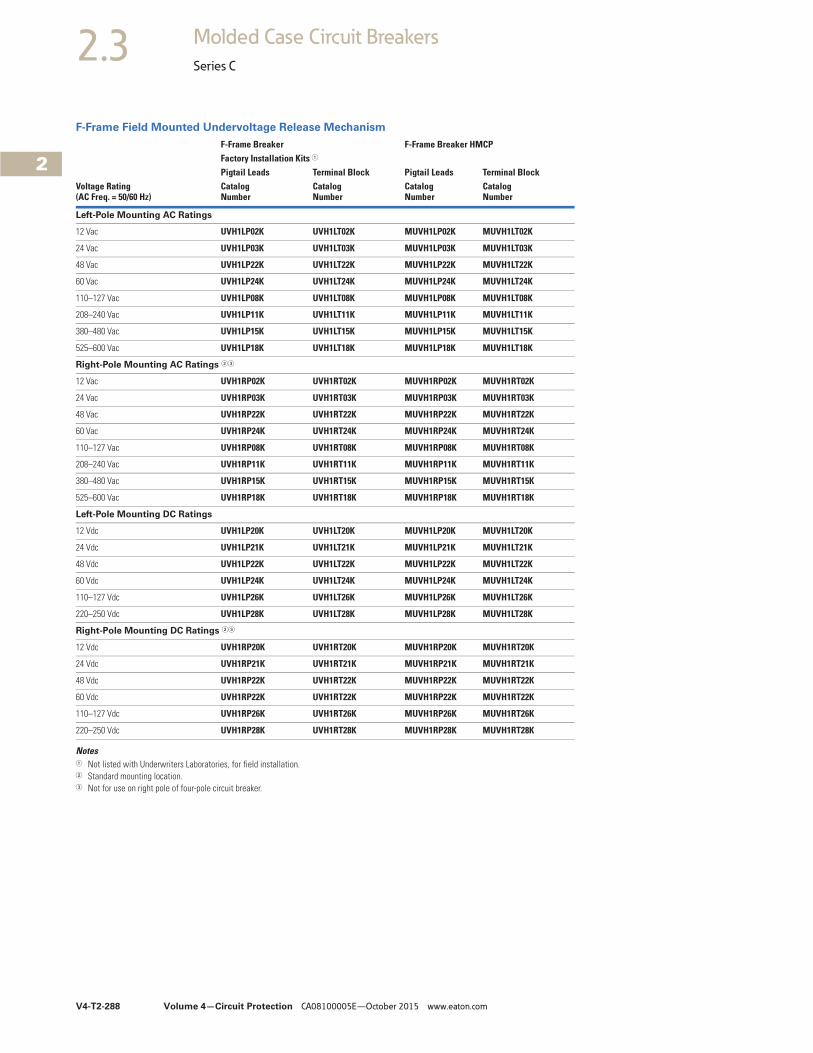
V4-T2-288 Volume 4—Circuit Protection CA08100005E—October 2015 www.eaton.com
2
2
2
2
2
2
2
2
2
2
2
2
2
2
2
2
2
2
2
2
2
2
2
2
2
2
2
2
2
2
2.3 Molded Case Circuit Breakers
Series C
F-Frame Field Mounted Undervoltage Release Mechanism
Notes1 Not listed with Underwriters Laboratories, for field installation.2 Standard mounting location.3 Not for use on right pole of four-pole circuit breaker.
Voltage Rating(AC Freq. = 50/60 Hz)
F-Frame Breaker F-Frame Breaker HMCPFactory Installation Kits 1
Pigtail Leads Terminal Block Pigtail Leads Terminal BlockCatalogNumber
CatalogNumber
CatalogNumber
CatalogNumber
Left-Pole Mounting AC Ratings
12 Vac UVH1LP02K UVH1LT02K MUVH1LP02K MUVH1LT02K
24 Vac UVH1LP03K UVH1LT03K MUVH1LP03K MUVH1LT03K
48 Vac UVH1LP22K UVH1LT22K MUVH1LP22K MUVH1LT22K
60 Vac UVH1LP24K UVH1LT24K MUVH1LP24K MUVH1LT24K
110–127 Vac UVH1LP08K UVH1LT08K MUVH1LP08K MUVH1LT08K
208–240 Vac UVH1LP11K UVH1LT11K MUVH1LP11K MUVH1LT11K
380–480 Vac UVH1LP15K UVH1LT15K MUVH1LP15K MUVH1LT15K
525–600 Vac UVH1LP18K UVH1LT18K MUVH1LP18K MUVH1LT18K
Right-Pole Mounting AC Ratings 23
12 Vac UVH1RP02K UVH1RT02K MUVH1RP02K MUVH1RT02K
24 Vac UVH1RP03K UVH1RT03K MUVH1RP03K MUVH1RT03K
48 Vac UVH1RP22K UVH1RT22K MUVH1RP22K MUVH1RT22K
60 Vac UVH1RP24K UVH1RT24K MUVH1RP24K MUVH1RT24K
110–127 Vac UVH1RP08K UVH1RT08K MUVH1RP08K MUVH1RT08K
208–240 Vac UVH1RP11K UVH1RT11K MUVH1RP11K MUVH1RT11K
380–480 Vac UVH1RP15K UVH1RT15K MUVH1RP15K MUVH1RT15K
525–600 Vac UVH1RP18K UVH1RT18K MUVH1RP18K MUVH1RT18K
Left-Pole Mounting DC Ratings
12 Vdc UVH1LP20K UVH1LT20K MUVH1LP20K MUVH1LT20K
24 Vdc UVH1LP21K UVH1LT21K MUVH1LP21K MUVH1LT21K
48 Vdc UVH1LP22K UVH1LT22K MUVH1LP22K MUVH1LT22K
60 Vdc UVH1LP24K UVH1LT24K MUVH1LP24K MUVH1LT24K
110–127 Vdc UVH1LP26K UVH1LT26K MUVH1LP26K MUVH1LT26K
220–250 Vdc UVH1LP28K UVH1LT28K MUVH1LP28K MUVH1LT28K
Right-Pole Mounting DC Ratings 23
12 Vdc UVH1RP20K UVH1RT20K MUVH1RP20K MUVH1RT20K
24 Vdc UVH1RP21K UVH1RT21K MUVH1RP21K MUVH1RT21K
48 Vdc UVH1RP22K UVH1RT22K MUVH1RP22K MUVH1RT22K
60 Vdc UVH1RP22K UVH1RT22K MUVH1RP22K MUVH1RT22K
110–127 Vdc UVH1RP26K UVH1RT26K MUVH1RP26K MUVH1RT26K
220–250 Vdc UVH1RP28K UVH1RT28K MUVH1RP28K MUVH1RT28K
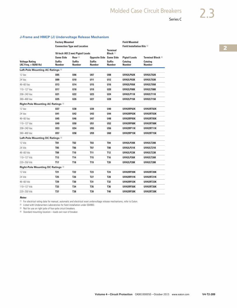
Volume 4—Circuit Protection CA08100005E—October 2015 www.eaton.com V4-T2-289
2
2
2
2
2
2
2
2
2
2
2
2
2
2
2
2
2
2
2
2
2
2
2
2
2
2
2
2
2
2
2.3Molded Case Circuit Breakers
Series C
J-Frame and HMCP (J) Undervoltage Release Mechanism
Notes1 For electrical rating data for manual, automatic and electrical reset undervoltage release mechanisms, refer to Eaton.2 Listed with Underwriters Laboratories for field installation under E64983.3 Not for use on right pole of four-pole circuit breakers.4 Standard mounting location—leads exit rear of breaker.
Voltage Rating(AC Freq. = 50/60 Hz)
Factory Mounted Field MountedConnection Type and Location Field Installation Kits 2
18-Inch (457.2 mm) Pigtail LeadsTerminal Block 1
Pigtail Leads Terminal Block 3Same Side Rear 2 Opposite Side Same SideSuffixNumber
SuffixNumber
SuffixNumber
SuffixNumber
CatalogNumber
CatalogNumber
Left-Pole Mounting AC Ratings 4
12 Vac U05 U06 U07 U08 UVH2LP02K UVH2LT02K
24 Vac U09 U10 U11 U12 UVH2LP03K UVH2LT03K
48–60 Vac U13 U14 U15 U16 UVH2LP05K UVH2LT05K
110–127 Vac U17 U18 U19 U20 UVH2LP08K UVH2LT08K
208–240 Vac U21 U22 U23 U24 UVH2LP11K UVH2LT11K
380–480 Vac U25 U26 U27 U28 UVH2LP15K UVH2LT15K
Right-Pole Mounting AC Ratings 3
12 Vac U37 U38 U39 U40 UVH2RP02K UVH2RT02K
24 Vac U41 U42 U43 U44 UVH2RP03K UVH2RT03K
48–60 Vac U45 U46 U47 U48 UVH2RP05K UVH2RT05K
110–127 Vac U49 U50 U51 U52 UVH2RP08K UVH2RT08K
208–240 Vac U53 U54 U55 U56 UVH2RP11K UVH2RT11K
380–480 Vac U57 U58 U59 U60 UVH2RP15K UVH2RT15K
Left-Pole Mounting DC Ratings 4
12 Vdc T01 T02 T03 T04 UVH2LP20K UVH2LT20K
24 Vdc T05 T06 T07 T08 UVH2LP21K UVH2LT21K
48–60 Vdc T09 T10 T11 T12 UVH2LP23K UVH2LT23K
110–127 Vdc T13 T14 T15 T16 UVH2LP26K UVH2LT26K
220–250 Vdc T17 T18 T19 T20 UVH2LP28K UVH2LT28K
Right-Pole Mounting DC Ratings 3
12 Vdc T21 T22 T23 T24 UVH2RP20K UVH2RT20K
24 Vdc T25 T26 T27 T28 UVH2RP21K UVH2RT21K
48–60 Vdc T29 T30 T31 T32 UVH2RP23K UVH2RT23K
110–127 Vdc T33 T34 T35 T36 UVH2RP26K UVH2RT26K
220–250 Vdc T37 T38 T39 T40 UVH2RP28K UVH2RT28K
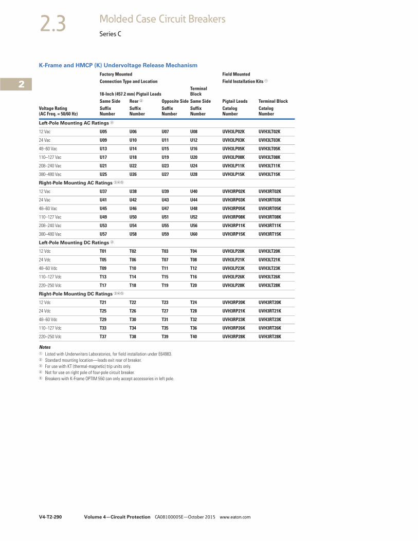
V4-T2-290 Volume 4—Circuit Protection CA08100005E—October 2015 www.eaton.com
2
2
2
2
2
2
2
2
2
2
2
2
2
2
2
2
2
2
2
2
2
2
2
2
2
2
2
2
2
2
2.3 Molded Case Circuit Breakers
Series C
K-Frame and HMCP (K) Undervoltage Release Mechanism
Notes1 Listed with Underwriters Laboratories, for field installation under E64983.2 Standard mounting location—leads exit rear of breaker.3 For use with KT (thermal-magnetic) trip units only.4 Not for use on right pole of four-pole circuit breaker.5 Breakers with K-Frame OPTIM 550 can only accept accessories in left pole.
Voltage Rating(AC Freq. = 50/60 Hz)
Factory Mounted Field MountedConnection Type and Location Field Installation Kits 1
18-Inch (457.2 mm) Pigtail LeadsTerminal Block
Pigtail Leads Terminal BlockSame Side Rear 2 Opposite Side Same SideSuffixNumber
SuffixNumber
SuffixNumber
SuffixNumber
CatalogNumber
CatalogNumber
Left-Pole Mounting AC Ratings 2
12 Vac U05 U06 U07 U08 UVH3LP02K UVH3LT02K
24 Vac U09 U10 U11 U12 UVH3LP03K UVH3LT03K
48–60 Vac U13 U14 U15 U16 UVH3LP05K UVH3LT05K
110–127 Vac U17 U18 U19 U20 UVH3LP08K UVH3LT08K
208–240 Vac U21 U22 U23 U24 UVH3LP11K UVH3LT11K
380–480 Vac U25 U26 U27 U28 UVH3LP15K UVH3LT15K
Right-Pole Mounting AC Ratings 345
12 Vac U37 U38 U39 U40 UVH3RP02K UVH3RT02K
24 Vac U41 U42 U43 U44 UVH3RP03K UVH3RT03K
48–60 Vac U45 U46 U47 U48 UVH3RP05K UVH3RT05K
110–127 Vac U49 U50 U51 U52 UVH3RP08K UVH3RT08K
208–240 Vac U53 U54 U55 U56 UVH3RP11K UVH3RT11K
380–480 Vac U57 U58 U59 U60 UVH3RP15K UVH3RT15K
Left-Pole Mounting DC Ratings 2
12 Vdc T01 T02 T03 T04 UVH3LP20K UVH3LT20K
24 Vdc T05 T06 T07 T08 UVH3LP21K UVH3LT21K
48–60 Vdc T09 T10 T11 T12 UVH3LP23K UVH3LT23K
110–127 Vdc T13 T14 T15 T16 UVH3LP26K UVH3LT26K
220–250 Vdc T17 T18 T19 T20 UVH3LP28K UVH3LT28K
Right-Pole Mounting DC Ratings 345
12 Vdc T21 T22 T23 T24 UVH3RP20K UVH3RT20K
24 Vdc T25 T26 T27 T28 UVH3RP21K UVH3RT21K
48–60 Vdc T29 T30 T31 T32 UVH3RP23K UVH3RT23K
110–127 Vdc T33 T34 T35 T36 UVH3RP26K UVH3RT26K
220–250 Vdc T37 T38 T39 T40 UVH3RP28K UVH3RT28K
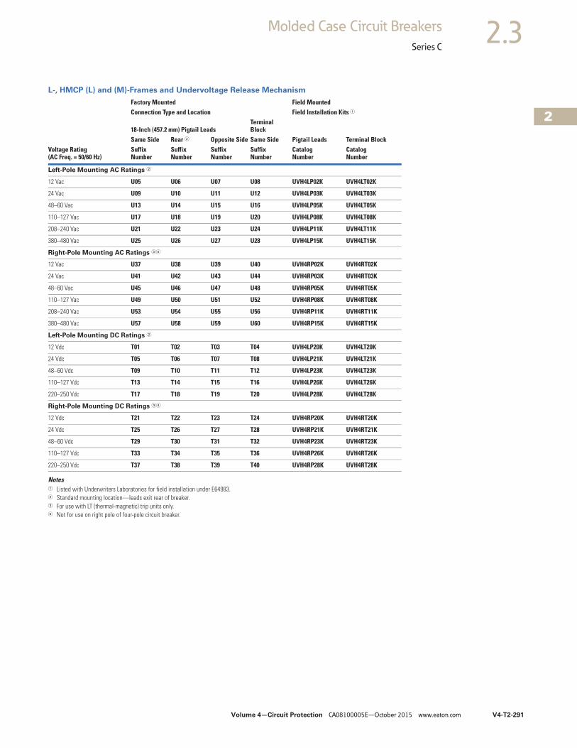
Volume 4—Circuit Protection CA08100005E—October 2015 www.eaton.com V4-T2-291
2
2
2
2
2
2
2
2
2
2
2
2
2
2
2
2
2
2
2
2
2
2
2
2
2
2
2
2
2
2
2.3Molded Case Circuit Breakers
Series C
L-, HMCP (L) and (M)-Frames and Undervoltage Release Mechanism
Notes1 Listed with Underwriters Laboratories for field installation under E64983.2 Standard mounting location—leads exit rear of breaker.3 For use with LT (thermal-magnetic) trip units only.4 Not for use on right pole of four-pole circuit breaker.
Voltage Rating(AC Freq. = 50/60 Hz)
Factory Mounted Field MountedConnection Type and Location Field Installation Kits 1
18-Inch (457.2 mm) Pigtail LeadsTerminal Block
Pigtail Leads Terminal BlockSame Side Rear 2 Opposite Side Same SideSuffixNumber
SuffixNumber
SuffixNumber
SuffixNumber
CatalogNumber
CatalogNumber
Left-Pole Mounting AC Ratings 2
12 Vac U05 U06 U07 U08 UVH4LP02K UVH4LT02K
24 Vac U09 U10 U11 U12 UVH4LP03K UVH4LT03K
48–60 Vac U13 U14 U15 U16 UVH4LP05K UVH4LT05K
110–127 Vac U17 U18 U19 U20 UVH4LP08K UVH4LT08K
208–240 Vac U21 U22 U23 U24 UVH4LP11K UVH4LT11K
380–480 Vac U25 U26 U27 U28 UVH4LP15K UVH4LT15K
Right-Pole Mounting AC Ratings 34
12 Vac U37 U38 U39 U40 UVH4RP02K UVH4RT02K
24 Vac U41 U42 U43 U44 UVH4RP03K UVH4RT03K
48–60 Vac U45 U46 U47 U48 UVH4RP05K UVH4RT05K
110–127 Vac U49 U50 U51 U52 UVH4RP08K UVH4RT08K
208–240 Vac U53 U54 U55 U56 UVH4RP11K UVH4RT11K
380–480 Vac U57 U58 U59 U60 UVH4RP15K UVH4RT15K
Left-Pole Mounting DC Ratings 2
12 Vdc T01 T02 T03 T04 UVH4LP20K UVH4LT20K
24 Vdc T05 T06 T07 T08 UVH4LP21K UVH4LT21K
48–60 Vdc T09 T10 T11 T12 UVH4LP23K UVH4LT23K
110–127 Vdc T13 T14 T15 T16 UVH4LP26K UVH4LT26K
220–250 Vdc T17 T18 T19 T20 UVH4LP28K UVH4LT28K
Right-Pole Mounting DC Ratings 34
12 Vdc T21 T22 T23 T24 UVH4RP20K UVH4RT20K
24 Vdc T25 T26 T27 T28 UVH4RP21K UVH4RT21K
48–60 Vdc T29 T30 T31 T32 UVH4RP23K UVH4RT23K
110–127 Vdc T33 T34 T35 T36 UVH4RP26K UVH4RT26K
220–250 Vdc T37 T38 T39 T40 UVH4RP28K UVH4RT28K
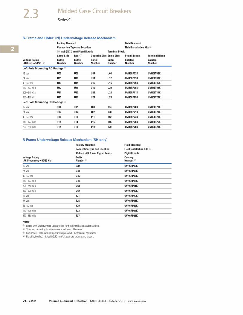
V4-T2-292 Volume 4—Circuit Protection CA08100005E—October 2015 www.eaton.com
2
2
2
2
2
2
2
2
2
2
2
2
2
2
2
2
2
2
2
2
2
2
2
2
2
2
2
2
2
2
2.3 Molded Case Circuit Breakers
Series C
N-Frame and HMCP (N) Undervoltage Release Mechanism
R-Frame Undervoltage Release Mechanism (RH only)
Notes1 Listed with Underwriters Laboratories for field installation under E64983.2 Standard mounting location—leads exit rear of breaker.3 Endurance: 500 electrical operations plus 2500 mechanical operations.4 Pigtail wire size: 18 AWG (0.82 mm2). Leads are orange and brown.
Voltage Rating(AC Freq. = 50/60 Hz)
Factory Mounted Field MountedConnection Type and Location Field Installation Kits 1
18-Inch (457.2 mm) Pigtail Leads Terminal BlockPigtail Leads Terminal BlockSame Side Rear 2 Opposite Side Same Side
SuffixNumber
SuffixNumber
SuffixNumber
SuffixNumber
CatalogNumber
CatalogNumber
Left-Pole Mounting AC Ratings 2
12 Vac U05 U06 U07 U08 UVH5LP02K UVH5LT02K
24 Vac U09 U10 U11 U12 UVH5LP03K UVH5LT03K
48–60 Vac U13 U14 U15 U16 UVH5LP05K UVH5LT05K
110–127 Vac U17 U18 U19 U20 UVH5LP08K UVH5LT08K
208–240 Vac U21 U22 U23 U24 UVH5LP11K UVH5LT11K
380–480 Vac U25 U26 U27 U28 UVH5LP29K UVH5LT29K
Left-Pole Mounting DC Ratings 2
12 Vdc T01 T02 T03 T04 UVH5LP20K UVH5LT20K
24 Vdc T05 T06 T07 T08 UVH5LP21K UVH5LT21K
48–60 Vdc T09 T10 T11 T12 UVH5LP23K UVH5LT23K
110–127 Vdc T13 T14 T15 T16 UVH5LP26K UVH5LT26K
220–250 Vdc T17 T18 T19 T20 UVH5LP28K UVH5LT28K
Voltage Rating (AC Frequency = 50/60 Hz)
Factory Mounted Field MountedConnection Type and Location Field Installation Kits 3
18-Inch (457.2 mm) Pigtail Leads Pigtail LeadsSuffixNumber 4
CatalogNumber 4
12 Vac U37 UVH6RP02K
24 Vac U41 UVH6RP03K
48–60 Vac U45 UVH6RP05K
110–127 Vac U49 UVH6RP08K
208–240 Vac U53 UVH6RP11K
380–500 Vac U57 UVH6RP29K
12 Vdc T21 UVH6RP20K
24 Vdc T25 UVH6RP21K
48–60 Vdc T29 UVH6RP23K
110–125 Vdc T33 UVH6RP26K
220–250 Vdc T37 UVH6RP28K
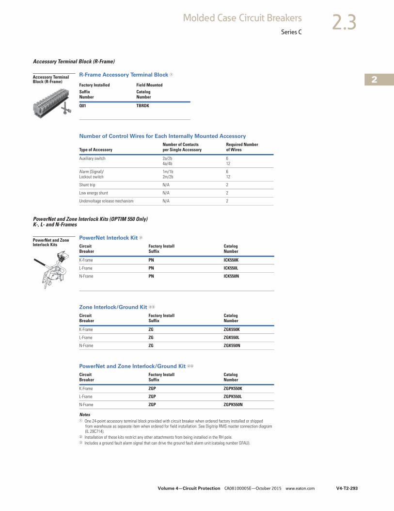
Volume 4—Circuit Protection CA08100005E—October 2015 www.eaton.com V4-T2-293
2
2
2
2
2
2
2
2
2
2
2
2
2
2
2
2
2
2
2
2
2
2
2
2
2
2
2
2
2
2
2.3Molded Case Circuit Breakers
Series C
Accessory Terminal Block (R-Frame)
R-Frame Accessory Terminal Block 1
Number of Control Wires for Each Internally Mounted Accessory
PowerNet and Zone Interlock Kits (OPTIM 550 Only) K-, L- and N-Frames
PowerNet Interlock Kit 2
Zone Interlock/Ground Kit 23
PowerNet and Zone Interlock/Ground Kit 23
Notes1 One 24-point accessory terminal block provided with circuit breaker when ordered factory installed or shipped
from warehouse as separate item when ordered for field installation. See Digitrip RMS master connection diagram (IL 29C714).
2 Installation of these kits restrict any other attachments from being installed in the RH pole.3 Includes a ground fault alarm signal that can drive the ground fault alarm unit (catalog number GFAU).
Factory Installed Field MountedSuffix Number
CatalogNumber
Q01 TBRDK
Type of AccessoryNumber of Contacts per Single Accessory
Required Numberof Wires
Auxiliary switch 2a/2b4a/4b
612
Alarm (Signal)/Lockout switch
1m/1b2m/2b
612
Shunt trip N/A 2
Low energy shunt N/A 2
Undervoltage release mechanism N/A 2
Circuit Breaker
Factory InstallSuffix
CatalogNumber
K-Frame PN ICK550K
L-Frame PN ICK550L
N-Frame PN ICK550N
Circuit Breaker
Factory InstallSuffix
CatalogNumber
K-Frame ZG ZGK550K
L-Frame ZG ZGK550L
N-Frame ZG ZGK550N
Circuit Breaker
Factory InstallSuffix
CatalogNumber
K-Frame ZGP ZGPK550K
L-Frame ZGP ZGPK550L
N-Frame ZGP ZGPK550N
Accessory Terminal Block (R-Frame)
PowerNet and Zone Interlock Kits
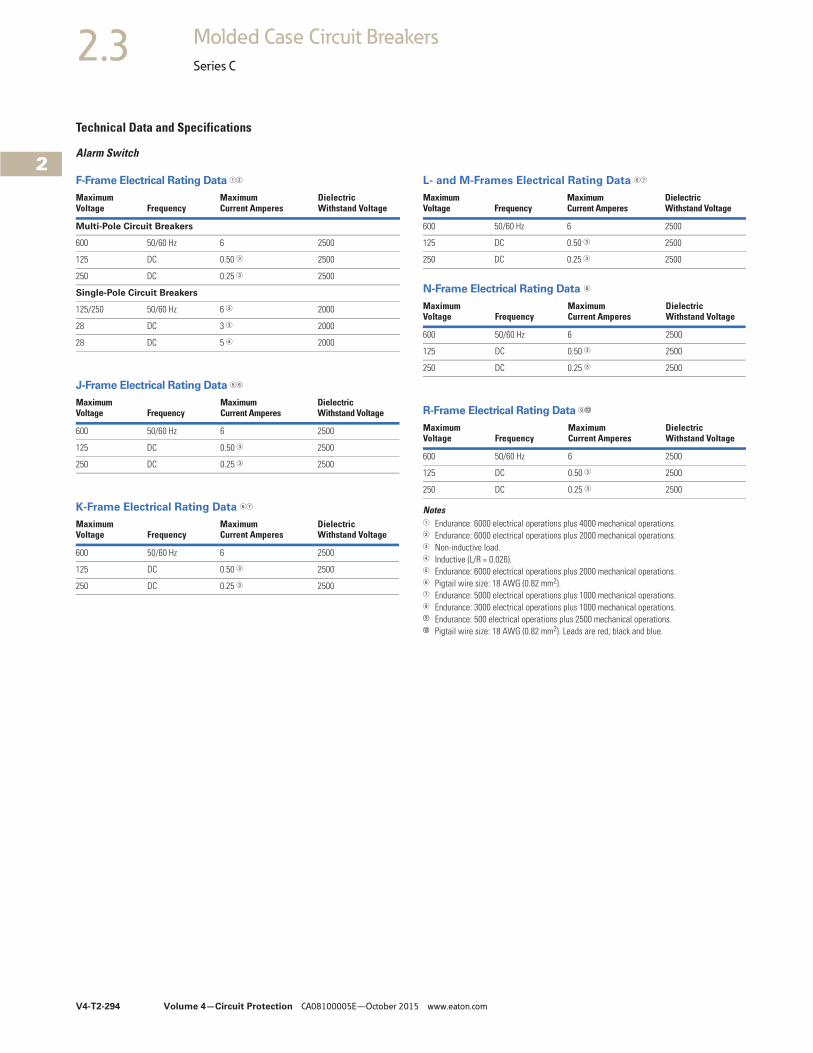
V4-T2-294 Volume 4—Circuit Protection CA08100005E—October 2015 www.eaton.com
2
2
2
2
2
2
2
2
2
2
2
2
2
2
2
2
2
2
2
2
2
2
2
2
2
2
2
2
2
2
2.3 Molded Case Circuit Breakers
Series C
Technical Data and Specifications
Alarm Switch
F-Frame Electrical Rating Data 12
J-Frame Electrical Rating Data 56
K-Frame Electrical Rating Data 67
L- and M-Frames Electrical Rating Data 67
N-Frame Electrical Rating Data 8
R-Frame Electrical Rating Data 9j
Notes1 Endurance: 6000 electrical operations plus 4000 mechanical operations.2 Endurance: 6000 electrical operations plus 2000 mechanical operations.3 Non-inductive load.4 Inductive (L/R = 0.026).5 Endurance: 6000 electrical operations plus 2000 mechanical operations.6 Pigtail wire size: 18 AWG (0.82 mm2).7 Endurance: 5000 electrical operations plus 1000 mechanical operations.8 Endurance: 3000 electrical operations plus 1000 mechanical operations.i Endurance: 500 electrical operations plus 2500 mechanical operations.j Pigtail wire size: 18 AWG (0.82 mm2). Leads are red, black and blue.
MaximumVoltage Frequency
Maximum Current Amperes
Dielectric Withstand Voltage
Multi-Pole Circuit Breakers
600 50/60 Hz 6 2500
125 DC 0.50 3 2500
250 DC 0.25 3 2500
Single-Pole Circuit Breakers
125/250 50/60 Hz 6 3 2000
28 DC 3 3 2000
28 DC 5 4 2000
MaximumVoltage Frequency
Maximum Current Amperes
Dielectric Withstand Voltage
600 50/60 Hz 6 2500
125 DC 0.50 3 2500
250 DC 0.25 3 2500
MaximumVoltage Frequency
Maximum Current Amperes
Dielectric Withstand Voltage
600 50/60 Hz 6 2500
125 DC 0.50 3 2500
250 DC 0.25 3 2500
MaximumVoltage Frequency
Maximum Current Amperes
Dielectric Withstand Voltage
600 50/60 Hz 6 2500
125 DC 0.50 3 2500
250 DC 0.25 3 2500
MaximumVoltage Frequency
Maximum Current Amperes
Dielectric Withstand Voltage
600 50/60 Hz 6 2500
125 DC 0.50 3 2500
250 DC 0.25 3 2500
MaximumVoltage Frequency
MaximumCurrent Amperes
DielectricWithstand Voltage
600 50/60 Hz 6 2500
125 DC 0.50 3 2500
250 DC 0.25 3 2500
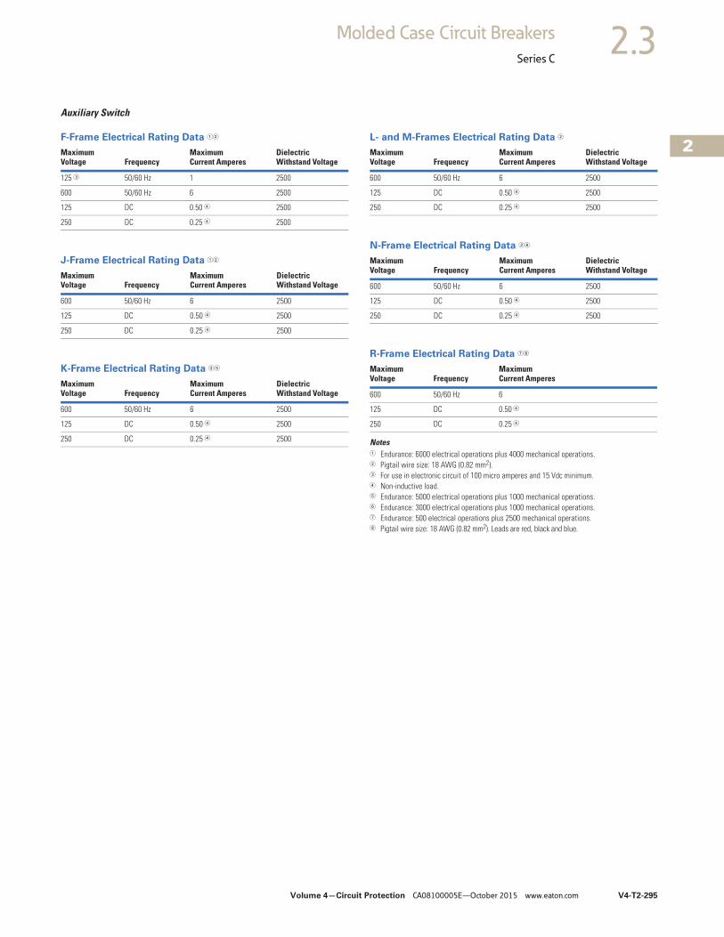
Volume 4—Circuit Protection CA08100005E—October 2015 www.eaton.com V4-T2-295
2
2
2
2
2
2
2
2
2
2
2
2
2
2
2
2
2
2
2
2
2
2
2
2
2
2
2
2
2
2
2.3Molded Case Circuit Breakers
Series C
Auxiliary Switch
F-Frame Electrical Rating Data 12
J-Frame Electrical Rating Data 12
K-Frame Electrical Rating Data 25
L- and M-Frames Electrical Rating Data 2
N-Frame Electrical Rating Data 26
R-Frame Electrical Rating Data 78
Notes1 Endurance: 6000 electrical operations plus 4000 mechanical operations.2 Pigtail wire size: 18 AWG (0.82 mm2).3 For use in electronic circuit of 100 micro amperes and 15 Vdc minimum.4 Non-inductive load.5 Endurance: 5000 electrical operations plus 1000 mechanical operations.6 Endurance: 3000 electrical operations plus 1000 mechanical operations.7 Endurance: 500 electrical operations plus 2500 mechanical operations.8 Pigtail wire size: 18 AWG (0.82 mm2). Leads are red, black and blue.
MaximumVoltage Frequency
Maximum Current Amperes
DielectricWithstand Voltage
125 3 50/60 Hz 1 2500
600 50/60 Hz 6 2500
125 DC 0.50 4 2500
250 DC 0.25 4 2500
MaximumVoltage Frequency
Maximum Current Amperes
Dielectric Withstand Voltage
600 50/60 Hz 6 2500
125 DC 0.50 4 2500
250 DC 0.25 4 2500
MaximumVoltage Frequency
MaximumCurrent Amperes
DielectricWithstand Voltage
600 50/60 Hz 6 2500
125 DC 0.50 4 2500
250 DC 0.25 4 2500
MaximumVoltage Frequency
Maximum Current Amperes
Dielectric Withstand Voltage
600 50/60 Hz 6 2500
125 DC 0.50 4 2500
250 DC 0.25 4 2500
MaximumVoltage Frequency
Maximum Current Amperes
DielectricWithstand Voltage
600 50/60 Hz 6 2500
125 DC 0.50 4 2500
250 DC 0.25 4 2500
MaximumVoltage Frequency
MaximumCurrent Amperes
600 50/60 Hz 6
125 DC 0.50 4
250 DC 0.25 4
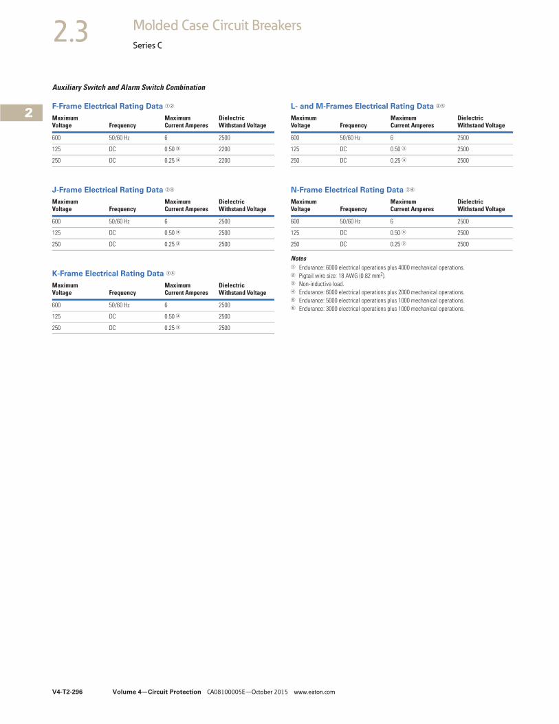
V4-T2-296 Volume 4—Circuit Protection CA08100005E—October 2015 www.eaton.com
2
2
2
2
2
2
2
2
2
2
2
2
2
2
2
2
2
2
2
2
2
2
2
2
2
2
2
2
2
2
2.3 Molded Case Circuit Breakers
Series C
Auxiliary Switch and Alarm Switch Combination
F-Frame Electrical Rating Data 12
J-Frame Electrical Rating Data 24
K-Frame Electrical Rating Data 25
L- and M-Frames Electrical Rating Data 25
N-Frame Electrical Rating Data 26
Notes1 Endurance: 6000 electrical operations plus 4000 mechanical operations.2 Pigtail wire size: 18 AWG (0.82 mm2).3 Non-inductive load.4 Endurance: 6000 electrical operations plus 2000 mechanical operations.5 Endurance: 5000 electrical operations plus 1000 mechanical operations.6 Endurance: 3000 electrical operations plus 1000 mechanical operations.
MaximumVoltage Frequency
Maximum Current Amperes
DielectricWithstand Voltage
600 50/60 Hz 6 2500
125 DC 0.50 3 2200
250 DC 0.25 3 2200
MaximumVoltage Frequency
MaximumCurrent Amperes
DielectricWithstand Voltage
600 50/60 Hz 6 2500
125 DC 0.50 3 2500
250 DC 0.25 3 2500
MaximumVoltage Frequency
MaximumCurrent Amperes
DielectricWithstand Voltage
600 50/60 Hz 6 2500
125 DC 0.50 3 2500
250 DC 0.25 3 2500
MaximumVoltage Frequency
MaximumCurrent Amperes
DielectricWithstand Voltage
600 50/60 Hz 6 2500
125 DC 0.50 3 2500
250 DC 0.25 3 2500
MaximumVoltage Frequency
MaximumCurrent Amperes
DielectricWithstand Voltage
600 50/60 Hz 6 2500
125 DC 0.50 3 2500
250 DC 0.25 3 2500
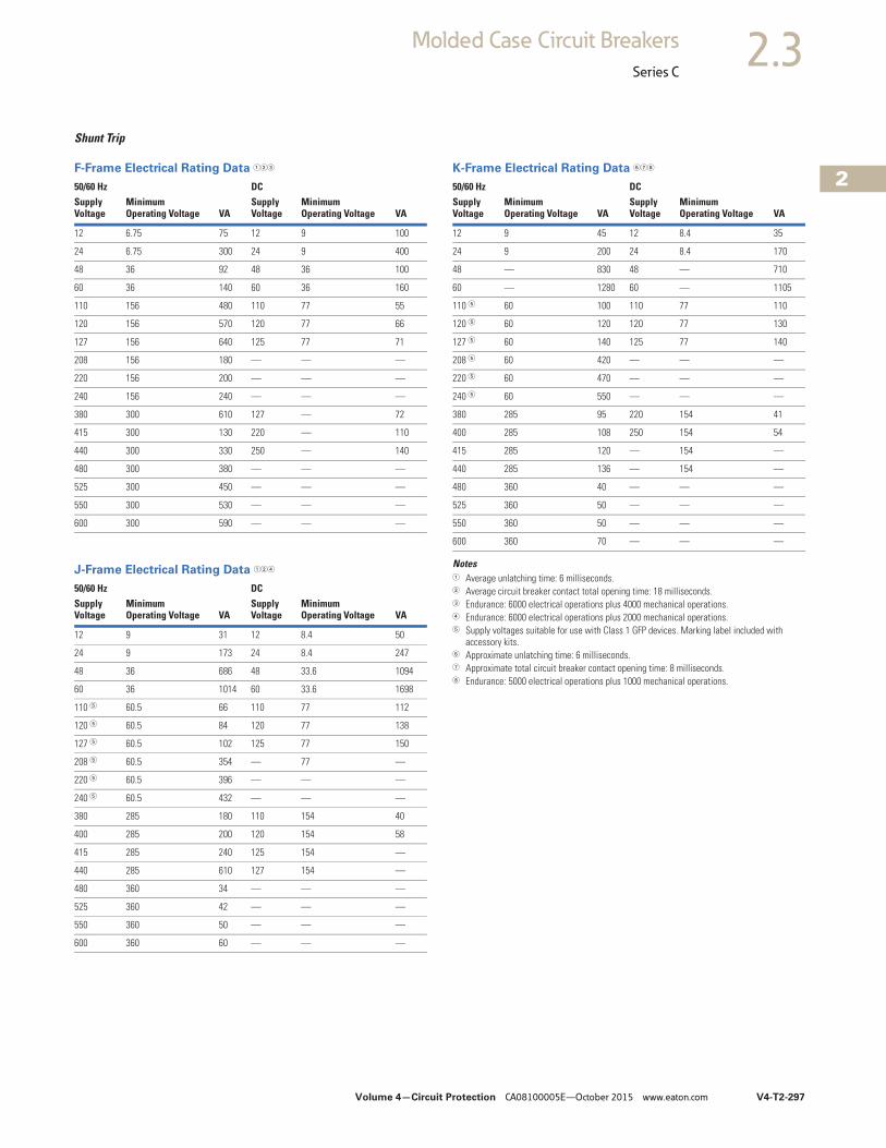
Volume 4—Circuit Protection CA08100005E—October 2015 www.eaton.com V4-T2-297
2
2
2
2
2
2
2
2
2
2
2
2
2
2
2
2
2
2
2
2
2
2
2
2
2
2
2
2
2
2
2.3Molded Case Circuit Breakers
Series C
Shunt Trip
F-Frame Electrical Rating Data 123
J-Frame Electrical Rating Data 124
K-Frame Electrical Rating Data 678
Notes1 Average unlatching time: 6 milliseconds.2 Average circuit breaker contact total opening time: 18 milliseconds.3 Endurance: 6000 electrical operations plus 4000 mechanical operations.4 Endurance: 6000 electrical operations plus 2000 mechanical operations.5 Supply voltages suitable for use with Class 1 GFP devices. Marking label included with
accessory kits.6 Approximate unlatching time: 6 milliseconds.7 Approximate total circuit breaker contact opening time: 8 milliseconds.8 Endurance: 5000 electrical operations plus 1000 mechanical operations.
50/60 Hz DCSupplyVoltage
MinimumOperating Voltage VA
SupplyVoltage
MinimumOperating Voltage VA
12 6.75 75 12 9 100
24 6.75 300 24 9 400
48 36 92 48 36 100
60 36 140 60 36 160
110 156 480 110 77 55
120 156 570 120 77 66
127 156 640 125 77 71
208 156 180 — — —
220 156 200 — — —
240 156 240 — — —
380 300 610 127 — 72
415 300 130 220 — 110
440 300 330 250 — 140
480 300 380 — — —
525 300 450 — — —
550 300 530 — — —
600 300 590 — — —
50/60 Hz DCSupplyVoltage
MinimumOperating Voltage VA
SupplyVoltage
MinimumOperating Voltage VA
12 9 31 12 8.4 50
24 9 173 24 8.4 247
48 36 686 48 33.6 1094
60 36 1014 60 33.6 1698
110 5 60.5 66 110 77 112
120 5 60.5 84 120 77 138
127 5 60.5 102 125 77 150
208 5 60.5 354 — 77 —
220 5 60.5 396 — — —
240 5 60.5 432 — — —
380 285 180 110 154 40
400 285 200 120 154 58
415 285 240 125 154 —
440 285 610 127 154 —
480 360 34 — — —
525 360 42 — — —
550 360 50 — — —
600 360 60 — — —
50/60 Hz DCSupplyVoltage
MinimumOperating Voltage VA
SupplyVoltage
MinimumOperating Voltage VA
12 9 45 12 8.4 35
24 9 200 24 8.4 170
48 — 830 48 — 710
60 — 1280 60 — 1105
110 5 60 100 110 77 110
120 5 60 120 120 77 130
127 5 60 140 125 77 140
208 5 60 420 — — —
220 5 60 470 — — —
240 5 60 550 — — —
380 285 95 220 154 41
400 285 108 250 154 54
415 285 120 — 154 —
440 285 136 — 154 —
480 360 40 — — —
525 360 50 — — —
550 360 50 — — —
600 360 70 — — —
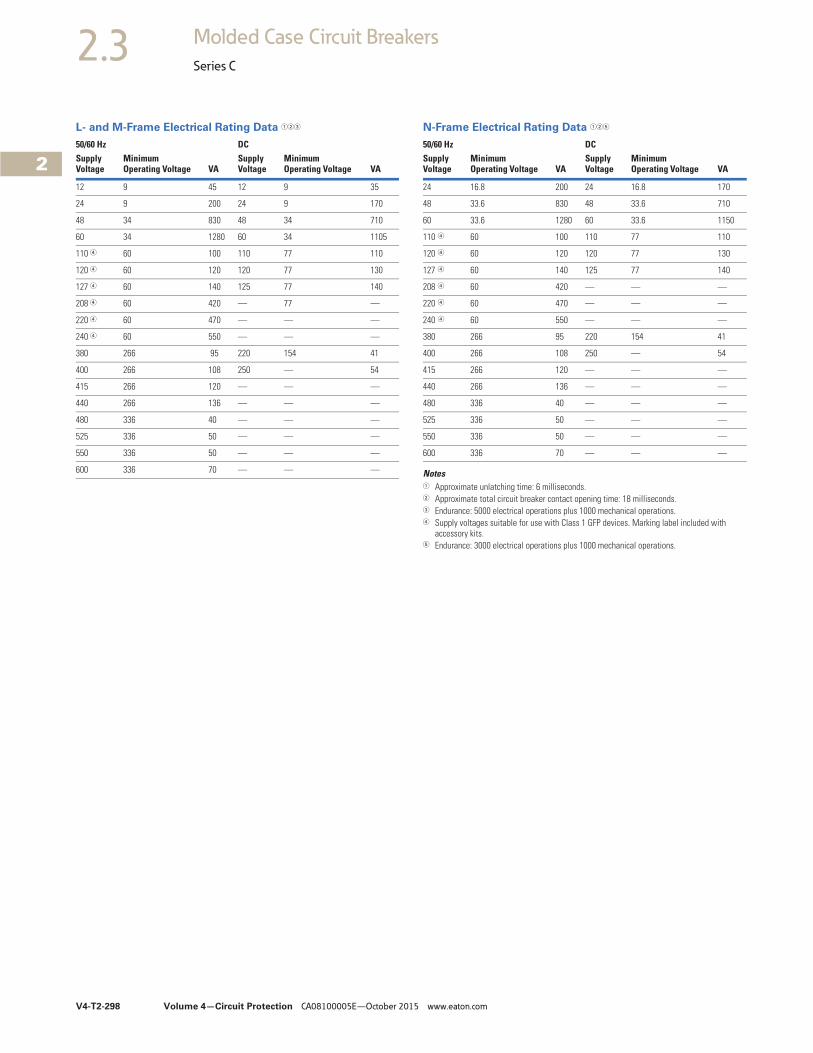
V4-T2-298 Volume 4—Circuit Protection CA08100005E—October 2015 www.eaton.com
2
2
2
2
2
2
2
2
2
2
2
2
2
2
2
2
2
2
2
2
2
2
2
2
2
2
2
2
2
2
2.3 Molded Case Circuit Breakers
Series C
L- and M-Frame Electrical Rating Data 123 N-Frame Electrical Rating Data 125
Notes1 Approximate unlatching time: 6 milliseconds.2 Approximate total circuit breaker contact opening time: 18 milliseconds.3 Endurance: 5000 electrical operations plus 1000 mechanical operations.4 Supply voltages suitable for use with Class 1 GFP devices. Marking label included with
accessory kits.5 Endurance: 3000 electrical operations plus 1000 mechanical operations.
50/60 Hz DCSupplyVoltage
MinimumOperating Voltage VA
SupplyVoltage
MinimumOperating Voltage VA
12 9 45 12 9 35
24 9 200 24 9 170
48 34 830 48 34 710
60 34 1280 60 34 1105
110 4 60 100 110 77 110
120 4 60 120 120 77 130
127 4 60 140 125 77 140
208 4 60 420 — 77 —
220 4 60 470 — — —
240 4 60 550 — — —
380 266 95 220 154 41
400 266 108 250 — 54
415 266 120 — — —
440 266 136 — — —
480 336 40 — — —
525 336 50 — — —
550 336 50 — — —
600 336 70 — — —
50/60 Hz DCSupplyVoltage
MinimumOperating Voltage VA
SupplyVoltage
MinimumOperating Voltage VA
24 16.8 200 24 16.8 170
48 33.6 830 48 33.6 710
60 33.6 1280 60 33.6 1150
110 4 60 100 110 77 110
120 4 60 120 120 77 130
127 4 60 140 125 77 140
208 4 60 420 — — —
220 4 60 470 — — —
240 4 60 550 — — —
380 266 95 220 154 41
400 266 108 250 — 54
415 266 120 — — —
440 266 136 — — —
480 336 40 — — —
525 336 50 — — —
550 336 50 — — —
600 336 70 — — —
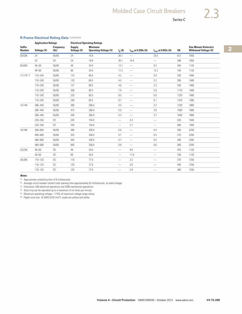
Volume 4—Circuit Protection CA08100005E—October 2015 www.eaton.com V4-T2-299
2
2
2
2
2
2
2
2
2
2
2
2
2
2
2
2
2
2
2
2
2
2
2
2
2
2
2
2
2
2
2.3Molded Case Circuit Breakers
Series C
R-Frame Electrical Rating Data 123456
Notes1 Approximate unlatching time of 6 milliseconds.2 Average circuit breaker contact total opening time approximately 62 milliseconds, at rated voltage.3 Endurance: 500 electrical operations and 2500 mechanical operations.4 Shunt trip can be operated up to a maximum of six times per minute.5 Maximum operating voltage—110% of maximum voltage range rating.6 Pigtail wire size: 18 AWG (0.82 mm2). Leads are yellow and white.
Application Ratings Electrical Operating RatingsSuffixNumber Voltage (V)
Frequency(Hz)
SupplyVoltage (V)
MinimumOperating Voltage (V) Ip (A) Irms at 0.250s (A) Irms at 0.033s (A) VA
One Minute DielectricWithstand Voltage (V)
03/03K 24 50/60 24 16.8 36.1 — 25.5 612 1050
24 DC 24 16.8 36.1 16.5 — 396 1050
05/05K 48–60 50/60 48 34.0 13.1 — 9.2 450 1120
48–60 50/60 60 34.0 17.2 — 12.2 740 1120
11/11K 3 110–240 50/60 110 60.5 4.2 — 3.0 330 1480
110–240 50/60 120 60.5 4.5 — 3.2 390 1480
110–240 50/60 127 60.5 4.6 — 3.3 430 1480
110–240 50/60 208 60.5 7.9 — 5.6 1170 1480
110–240 50/60 220 60.5 8.5 — 6.0 1370 1480
110–240 50/60 240 60.5 8.7 — 6.1 1470 1480
14/14K 380–440 50/60 380 266.0 4.5 — 3.2 1220 1880
380–440 50/60 415 266.0 5.0 — 3.6 1500 1880
380–440 50/60 440 266.0 5.3 — 3.7 1640 1880
220–250 DC 220 154.0 — 2.4 — 530 1500
220–250 DC 250 154.0 — 2.7 — 680 1500
18/18K 480–600 50/60 480 336.0 0.6 — 0.4 200 2200
480–600 50/60 525 336.0 0.7 — 0.5 270 2200
480–600 50/60 550 336.0 0.7 — 0.5 280 2200
480–600 50/60 600 336.0 0.8 — 0.6 360 2200
23/23K 48–60 DC 48 34.0 — 9.8 — 470 1120
48–60 DC 60 34.0 — 11.6 — 700 1120
26/26K 110–125 DC 110 77.0 — 3.3 — 370 1250
110–125 DC 120 77.0 — 3.6 — 440 1250
110–125 DC 125 77.0 — 3.8 — 480 1250

V4-T2-300 Volume 4—Circuit Protection CA08100005E—October 2015 www.eaton.com
2
2
2
2
2
2
2
2
2
2
2
2
2
2
2
2
2
2
2
2
2
2
2
2
2
2
2
2
2
2
2.3 Molded Case Circuit Breakers
Series C
Undervoltage Release Mechanism
F-Frame Electrical Rating Data 1
J-Frame Electrical Rating Data 23
Notes1 Endurance: 6000 electrical operations plus 4000 mechanical operations.2 Endurance: 6000 electrical operations plus 2000 mechanical operations.3 For electrical rating data for manual, automatic and electrical reset undervoltage release mechanisms, refer to Eaton.
50/60 Hz DC
SupplyVoltage
Dropout Voltage Pickup Voltage
VASupplyVoltage
Dropout Voltage Pickup Voltage
VAMinimum Maximum Maximum Minimum Maximum Maximum
12 4.2 6.3 7.6 1.3 12 4.2 8.4 10.2 2.8
12 4.2 6.3 7.6 2.5 12 4.2 8.4 10.2 2.8
24 8.4 16.8 20.4 1.4 24 8.4 16.8 20.4 1.6
48 21.0 33.6 40.8 1.2 48 21.0 33.6 40.8 1.3
60 21.0 33.6 40.8 1.9 60 21.0 33.6 40.8 2.0
110 44.5 77.0 93.5 1.3 110 44.5 77.0 93.5 1.5
120 44.5 77.0 93.5 1.5 120 44.5 77.0 93.5 1.7
127 44.5 77.0 93.5 1.7 125 44.5 77.0 93.5 1.9
208 84.0 145.6 176.8 2.2 220 87.5 154.0 187.0 2.6
220 84.0 145.6 176.8 2.4 250 87.5 154.0 187.0 3.4
240 84.0 145.6 176.8 2.9 — — — — —
380 168.0 266.0 323.0 2.9 — — — — —
415 168.0 266.0 323.0 3.5 — — — — —
440 168.0 266.0 323.0 3.9 — — — — —
480 168.0 266.0 323.0 4.6 — — — — —
525 210.0 367.0 446.0 4.3 — — — — —
550 210.0 367.0 446.0 4.8 — — — — —
600 210.0 367.0 446.0 5.8 — — — — —
50/60 Hz DC
SupplyVoltage
Dropout Voltage Pickup Voltage
VASupplyVoltage
Dropout Voltage Pickup Voltage
VAMinimum Maximum Maximum Minimum Maximum Maximum
12 4.2 8.4 10.2 1.9 12 4.2 8.4 10.2 1.6
24 8.4 16.8 20.4 3.9 24 8.4 16.8 20.4 3.1
48 21.0 33.6 40.8 2.5 48 21.0 33.6 40.8 2.0
60 21.0 33.6 40.8 3.8 60 21.0 33.6 40.8 3.1
110 44.5 77.0 93.5 1.8 110 44.5 77.0 93.5 1.6
120 44.5 77.0 93.5 2.1 120 44.5 77.0 93.5 1.9
127 44.5 77.0 93.5 2.4 125 44.5 77.0 93.5 2.2
208 84.0 145.6 176.8 2.7 220 87.5 154.0 187.0 3.1
220 84.0 145.6 176.8 3.1 250 87.5 154.0 187.0 4.0
240 84.0 145.6 176.8 3.8 — — — — —
380 168.0 266.0 323.0 3.4 — — — — —
415 168.0 266.0 323.0 4.0 — — — — —
440 168.0 266.0 323.0 4.6 — — — — —
480 168.0 266.0 323.0 5.4 — — — — —
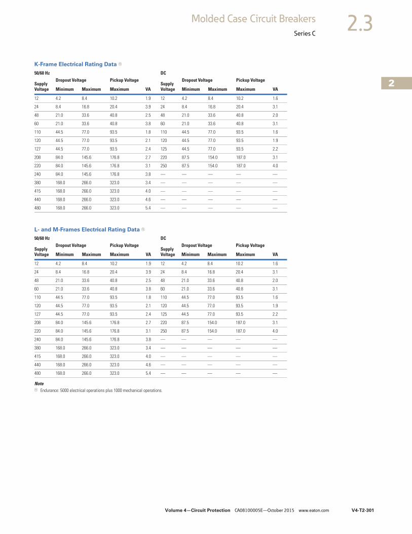
Volume 4—Circuit Protection CA08100005E—October 2015 www.eaton.com V4-T2-301
2
2
2
2
2
2
2
2
2
2
2
2
2
2
2
2
2
2
2
2
2
2
2
2
2
2
2
2
2
2
2.3Molded Case Circuit Breakers
Series C
K-Frame Electrical Rating Data 1
L- and M-Frames Electrical Rating Data 1
Note1 Endurance: 5000 electrical operations plus 1000 mechanical operations.
50/60 Hz DC
SupplyVoltage
Dropout Voltage Pickup Voltage
VASupplyVoltage
Dropout Voltage Pickup Voltage
VAMinimum Maximum Maximum Minimum Maximum Maximum
12 4.2 8.4 10.2 1.9 12 4.2 8.4 10.2 1.6
24 8.4 16.8 20.4 3.9 24 8.4 16.8 20.4 3.1
48 21.0 33.6 40.8 2.5 48 21.0 33.6 40.8 2.0
60 21.0 33.6 40.8 3.8 60 21.0 33.6 40.8 3.1
110 44.5 77.0 93.5 1.8 110 44.5 77.0 93.5 1.6
120 44.5 77.0 93.5 2.1 120 44.5 77.0 93.5 1.9
127 44.5 77.0 93.5 2.4 125 44.5 77.0 93.5 2.2
208 84.0 145.6 176.8 2.7 220 87.5 154.0 187.0 3.1
220 84.0 145.6 176.8 3.1 250 87.5 154.0 187.0 4.0
240 84.0 145.6 176.8 3.8 — — — — —
380 168.0 266.0 323.0 3.4 — — — — —
415 168.0 266.0 323.0 4.0 — — — — —
440 168.0 266.0 323.0 4.6 — — — — —
480 168.0 266.0 323.0 5.4 — — — — —
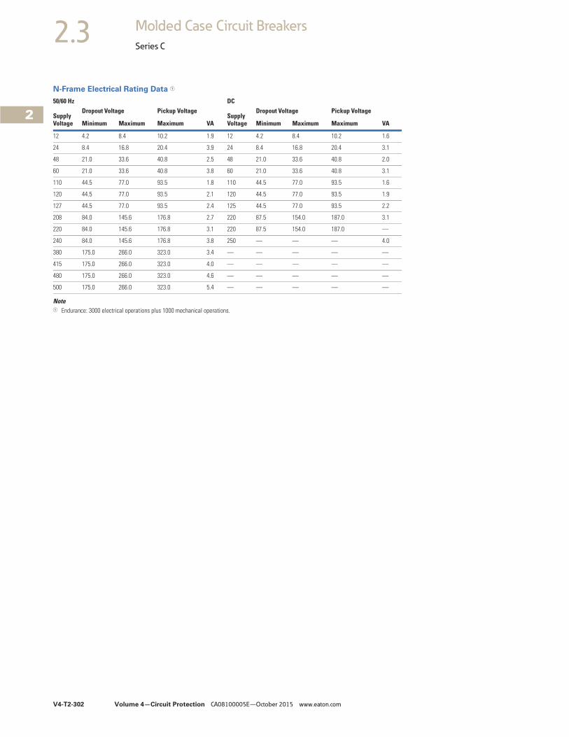
V4-T2-302 Volume 4—Circuit Protection CA08100005E—October 2015 www.eaton.com
2
2
2
2
2
2
2
2
2
2
2
2
2
2
2
2
2
2
2
2
2
2
2
2
2
2
2
2
2
2
2.3 Molded Case Circuit Breakers
Series C
N-Frame Electrical Rating Data 1
Note1 Endurance: 3000 electrical operations plus 1000 mechanical operations.
50/60 Hz DC
SupplyVoltage
Dropout Voltage Pickup Voltage
VASupplyVoltage
Dropout Voltage Pickup Voltage
VAMinimum Maximum Maximum Minimum Maximum Maximum
12 4.2 8.4 10.2 1.9 12 4.2 8.4 10.2 1.6
24 8.4 16.8 20.4 3.9 24 8.4 16.8 20.4 3.1
48 21.0 33.6 40.8 2.5 48 21.0 33.6 40.8 2.0
60 21.0 33.6 40.8 3.8 60 21.0 33.6 40.8 3.1
110 44.5 77.0 93.5 1.8 110 44.5 77.0 93.5 1.6
120 44.5 77.0 93.5 2.1 120 44.5 77.0 93.5 1.9
127 44.5 77.0 93.5 2.4 125 44.5 77.0 93.5 2.2
208 84.0 145.6 176.8 2.7 220 87.5 154.0 187.0 3.1
220 84.0 145.6 176.8 3.1 220 87.5 154.0 187.0 —
240 84.0 145.6 176.8 3.8 250 — — — 4.0
380 175.0 266.0 323.0 3.4 — — — — —
415 175.0 266.0 323.0 4.0 — — — — —
480 175.0 266.0 323.0 4.6 — — — — —
500 175.0 266.0 323.0 5.4 — — — — —
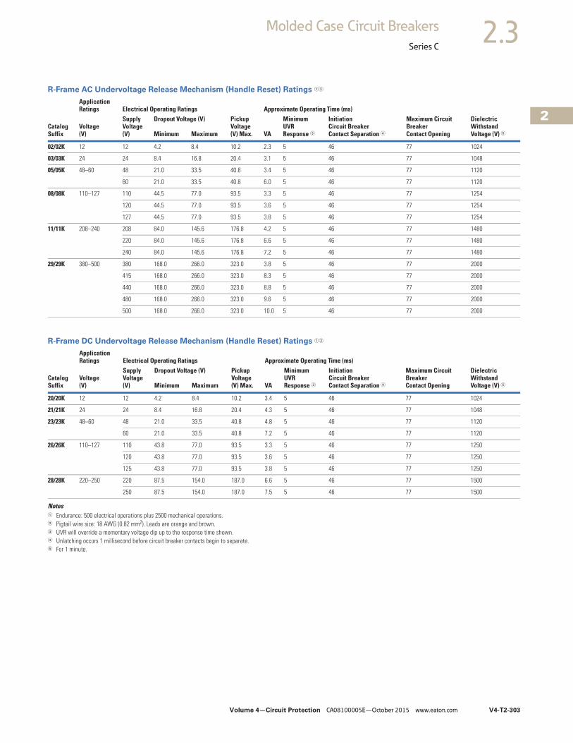
Volume 4—Circuit Protection CA08100005E—October 2015 www.eaton.com V4-T2-303
2
2
2
2
2
2
2
2
2
2
2
2
2
2
2
2
2
2
2
2
2
2
2
2
2
2
2
2
2
2
2.3Molded Case Circuit Breakers
Series C
R-Frame AC Undervoltage Release Mechanism (Handle Reset) Ratings 12
R-Frame DC Undervoltage Release Mechanism (Handle Reset) Ratings 12
Notes1 Endurance: 500 electrical operations plus 2500 mechanical operations.2 Pigtail wire size: 18 AWG (0.82 mm2). Leads are orange and brown.3 UVR will override a momentary voltage dip up to the response time shown.4 Unlatching occurs 1 millisecond before circuit breaker contacts begin to separate.5 For 1 minute.
CatalogSuffix
ApplicationRatings Electrical Operating Ratings Approximate Operating Time (ms)
Voltage(V)
SupplyVoltage(V)
Dropout Voltage (V) PickupVoltage(V) Max. VA
MinimumUVRResponse 3
InitiationCircuit BreakerContact Separation 4
Maximum CircuitBreakerContact Opening
DielectricWithstandVoltage (V) 5Minimum Maximum
02/02K 12 12 4.2 8.4 10.2 2.3 5 46 77 1024
03/03K 24 24 8.4 16.8 20.4 3.1 5 46 77 1048
05/05K 48–60 48 21.0 33.5 40.8 3.4 5 46 77 1120
60 21.0 33.5 40.8 6.0 5 46 77 1120
08/08K 110–127 110 44.5 77.0 93.5 3.3 5 46 77 1254
120 44.5 77.0 93.5 3.6 5 46 77 1254
127 44.5 77.0 93.5 3.8 5 46 77 1254
11/11K 208–240 208 84.0 145.6 176.8 4.2 5 46 77 1480
220 84.0 145.6 176.8 6.6 5 46 77 1480
240 84.0 145.6 176.8 7.2 5 46 77 1480
29/29K 380–500 380 168.0 266.0 323.0 3.8 5 46 77 2000
415 168.0 266.0 323.0 8.3 5 46 77 2000
440 168.0 266.0 323.0 8.8 5 46 77 2000
480 168.0 266.0 323.0 9.6 5 46 77 2000
500 168.0 266.0 323.0 10.0 5 46 77 2000
CatalogSuffix
ApplicationRatings Electrical Operating Ratings Approximate Operating Time (ms)
Voltage(V)
SupplyVoltage(V)
Dropout Voltage (V) PickupVoltage(V) Max. VA
MinimumUVRResponse 3
InitiationCircuit BreakerContact Separation 4
Maximum CircuitBreakerContact Opening
DielectricWithstandVoltage (V) 5Minimum Maximum
20/20K 12 12 4.2 8.4 10.2 3.4 5 46 77 1024
21/21K 24 24 8.4 16.8 20.4 4.3 5 46 77 1048
23/23K 48–60 48 21.0 33.5 40.8 4.8 5 46 77 1120
60 21.0 33.5 40.8 7.2 5 46 77 1120
26/26K 110–127 110 43.8 77.0 93.5 3.3 5 46 77 1250
120 43.8 77.0 93.5 3.6 5 46 77 1250
125 43.8 77.0 93.5 3.8 5 46 77 1250
28/28K 220–250 220 87.5 154.0 187.0 6.6 5 46 77 1500
250 87.5 154.0 187.0 7.5 5 46 77 1500
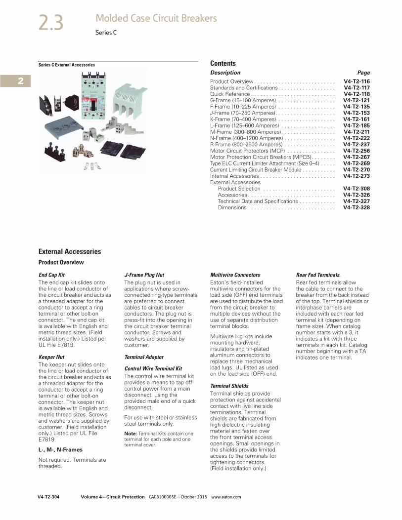
V4-T2-304 Volume 4—Circuit Protection CA08100005E—October 2015 www.eaton.com
2
2
2
2
2
2
2
2
2
2
2
2
2
2
2
2
2
2
2
2
2
2
2
2
2
2
2
2
2
2
2.3 Molded Case Circuit Breakers
Series C
Series C External Accessories ContentsDescription Page
Product Overview . . . . . . . . . . . . . . . . . . . . . . . . . . . V4-T2-116Standards and Certifications. . . . . . . . . . . . . . . . . . . V4-T2-117Quick Reference . . . . . . . . . . . . . . . . . . . . . . . . . . . . V4-T2-118G-Frame (15–100 Amperes) . . . . . . . . . . . . . . . . . . . V4-T2-121F-Frame (10–225 Amperes) . . . . . . . . . . . . . . . . . . . V4-T2-135J-Frame (70–250 Amperes). . . . . . . . . . . . . . . . . . . . V4-T2-153K-Frame (70–400 Amperes) . . . . . . . . . . . . . . . . . . . V4-T2-161L-Frame (125–600 Amperes) . . . . . . . . . . . . . . . . . . V4-T2-185M-Frame (300–800 Amperes). . . . . . . . . . . . . . . . . . V4-T2-211N-Frame (400–1200 Amperes) . . . . . . . . . . . . . . . . . V4-T2-222R-Frame (800–2500 Amperes) . . . . . . . . . . . . . . . . . V4-T2-237Motor Circuit Protectors (MCP) . . . . . . . . . . . . . . . . V4-T2-256Motor Protection Circuit Breakers (MPCB) . . . . . . . . V4-T2-267Type ELC Current Limiter Attachment (Size 0–4) . . . . . V4-T2-269Current Limiting Circuit Breaker Module . . . . . . . . . . . V4-T2-270Internal Accessories . . . . . . . . . . . . . . . . . . . . . . . . . V4-T2-273External Accessories
Product Selection . . . . . . . . . . . . . . . . . . . . . . . . V4-T2-308Accessories . . . . . . . . . . . . . . . . . . . . . . . . . . . . . V4-T2-326Technical Data and Specifications . . . . . . . . . . . . V4-T2-327Dimensions . . . . . . . . . . . . . . . . . . . . . . . . . . . . . V4-T2-328
External AccessoriesProduct Overview
End Cap KitThe end cap kit slides onto the line or load conductor of the circuit breaker and acts as a threaded adapter for the conductor to accept a ring terminal or other bolt-on connector. The end cap kit is available with English and metric thread sizes. (Field installation only.) Listed per UL File E7819.
Keeper NutThe keeper nut slides onto the line or load conductor of the circuit breaker and acts as a threaded adapter for the conductor to accept a ring terminal or other bolt-on connector. The keeper nut is available with English and metric thread sizes. Screws and washers are supplied by customer. (Field installation only.) Listed per UL File E7819.
L-, M-, N-Frames
Not required. Terminals are threaded.
J-Frame Plug NutThe plug nut is used in applications where screw-connected ring-type terminals are preferred to connect cables to circuit breaker conductors. The plug nut is press-fit into the opening in the circuit breaker terminal conductor. Screws and washers are supplied by customer.
Terminal Adapter
Control Wire Terminal KitThe control wire terminal kit provides a means to tap off control power from a main disconnect, using the provided male end of a quick disconnect.
For use with steel or stainless steel terminals only.
Note: Terminal Kits contain one terminal for each pole and one terminal cover.
Multiwire ConnectorsEaton’s field-installed multiwire connectors for the load side (OFF) end terminals are used to distribute the load from the circuit breaker to multiple devices without the use of separate distribution terminal blocks.
Multiwire lug kits include mounting hardware, insulators and tin-plated aluminum connectors to replace three mechanical load lugs. UL listed as used on the load side (OFF) end.
Terminal ShieldsTerminal shields provide protection against accidental contact with live line side terminations. Terminal shields are fabricated from high dielectric insulating material and fasten over the front terminal access openings. Small openings in the shields provide limited access to the terminals for tightening connectors. (Field installation only.)
Rear Fed Terminals.Rear fed terminals allow the cable to connect to the breaker from the back instead of the top. Terminal shields or interphase barriers are included with each rear fed terminal kit (depending on frame size). When catalog number starts with a 3, it indicates a kit with three terminals in each kit. Catalog number beginning with a TA indicates one terminal.
Volume 4—Circuit Protection CA08100005E—October 2015 www.eaton.com V4-T2-305
2
2
2
2
2
2
2
2
2
2
2
2
2
2
2
2
2
2
2
2
2
2
2
2
2
2
2
2
2
2
2.3Molded Case Circuit Breakers
Series C
Terminal End CoversThe terminal end covers are designed for use in motor control center applications where, because of confined spaces, line side conductors are normally custom fitted. The molded end covers are made of high dielectric glass-polyester and slide over the line ends of the circuit breaker. Close fitting conductor openings are molded into the end covers. The end cover and circuit breaker case fit together to form terminal compartments that isolate discharged ionizing gases during circuit breaker tripping. Terminal end covers are available with two conductor opening diameters, 0.25-inch (6.4 mm) and 0.41-inch (10.4 mm), and are listed per UL File E7819. (Field installation only.)
Interphase BarriersThe interphase barriers provide additional electrical clearance between circuit breaker poles for special termination applications. The barriers are high dielectric insulating plates that are installed in the molded slots between the terminals. (Field installation only.) Two per package.
Base Mounting PlateSuitable for mounting six single-pole circuit breakers.
DIN Rail AdapterFor use with standard 35 mm DIN rail such as, 35 x 7.5 or 35 x 15 mm per DIN EN50022.
Adapter mounting screws included are for use with two- and three-pole circuit breakers. Adapters for single-pole circuit breakers clip into the base molding.
Key Operated Attachment
Lock Dog (Non-Padlockable)
Non-Padlockable Handle BlockThe non-padlockable handle block secures the circuit breaker handle in either the ON or OFF position. (Trip-free operation allows the circuit breaker to trip when the
handle block holds the circuit breaker handle in the ON position.) The device is positioned over the circuit breaker handle and secured by a setscrew to deter accidental operation of the circuit breaker handle. Listed per UL File E7819. (Field installation only.)
Padlockable Handle
Padlockable Handle LockThe device is positioned in the cover opening to prevent handle movement. Will accommodate one 5/16-inch (8 mm) padlock.
Snap-on Padlockable Handle Lock HaspThe snap-on padlockable handle lock allows the handle to be locked in the OFF or ON position. (Trip-free operation allows the circuit breaker to trip when the handle lock holds the circuit breaker handle in the ON position.) This device was designed for use on the single-pole circuit breaker, but may be used on one-, two-, three- and four-pole styles. The handle lock snaps onto the escutcheon area of the handle with an optional retaining screw for added secureness. The handle lock will accommodate one padlock with a 1/4-inch (6.4 mm) shackle. Listed per UL File E7819. (Field installation only.)
Padlockable Handle Lock Hasp The padlockable handle lock hasp allows the handle to be locked in the ON or OFF position. (Trip-free operation allows the circuit breaker to trip when the handle lock holds the circuit breaker handle in the ON position.) The hasp mounts on the circuit breaker cover within the trimline. The cover is predrilled on both sides of the operating handle so that the hasp can be mounted on either side of the handle. The hasp will accommodate up to three padlocks with 1/4-inch (6.4 mm) shackles, one per circuit breaker. Listed per UL File E7819. (Field installation only.)
Cylinder LockThe cylinder lock internally blocks the trip bar in the tripped position to prevent the circuit breaker from being switched to ON. The cylinder lock is factory installed in the left pole only of the circuit breaker cover. Other internally mounted accessories cannot be installed in the same pole as the cylinder lock. (Factory installation only.)
Key Interlock Kit (Lock Not Included) The key interlock is used to externally lock the circuit breaker handle in the OFF position. When the key interlock is locked, an extended deadbolt blocks movement of the circuit breaker handle. Uniquely coded keys are removable only with the deadbolt extended. Each coded key controls a group of circuit breakers for a given specific customer installation.
The key interlock assembly is Underwriters Laboratories listed for field installation under UL File E7819 and consists of a mounting kit and a purchaser supplied deadbolt lock. The mounting kit comprises a mounting plate, which is secured to the circuit breaker cover in either the left- or right-pole position, key interlock mounting screws, and a wire seal. Specific mounting kits are required for individual key interlock types.
Sliding Bar Interlock The sliding bar interlock provides mechanical interlocking between two adjacent three-pole circuit breakers. It is installed on the enclosure cover between the circuit breakers. When the sliding bar interlock handle is moved from one side to the other, a bar extends to alternately block movement of the circuit breaker handles and prevents both circuit breakers from being switched to ON at the same time. Sliding bar interlocks are not UL listed. (Field installation only.)
Walking Beam Interlock The walking beam Interlock provides mechanical interlocking between two adjacent circuit breakers of the same pole configuration. The walking beam interlock mounts on a bracket behind and between the circuit breakers. A plunger on each end of the beam is inserted through an access hole in the back plate and base of each circuit breaker. The walking beam interlock prevents both circuit breakers from being switched ON at the same time. If a walking beam interlock is installed, the wiring troughs in the back of the circuit breaker case are blocked by the plungers and cannot be used for cross wiring. Factory modified circuit breakers are required for this application. UL File E38116.
Electrical Operator The electrical (solenoid) operator is a single solenoid mechanism that enables local and remote circuit breaker ON, OFF, and reset switching. The electrical operator is mounted on the circuit breaker cover within the trimline of the circuit breaker. The electrical operator uses a unique bi-stable latch that allows the device to operate using one solenoid. The accessory provides high-speed switching with a maximum operating time of 5 cycles(80 mS), making it suitable for generator synchronizing applications.
Means are provided for remote electrical operation and for local manual operation. A special slide includes provisions for padlocking the circuit breaker handle in the OFF position. The slide will accept three padlock shackles with a maximum diameter of 1/4-inch (6.4 mm) each.An interlock electrically disconnects the solenoid when the electrical operator cover is removed. The rating data tables provide electrical rating data for the electrical (solenoid) operator.
V4-T2-306 Volume 4—Circuit Protection CA08100005E—October 2015 www.eaton.com
2
2
2
2
2
2
2
2
2
2
2
2
2
2
2
2
2
2
2
2
2
2
2
2
2
2
2
2
2
2
2.3 Molded Case Circuit Breakers
Series C
The electrical (motor) operator allows the circuit’s breaker to be opened, closed or reset remotely. It also has a lock-off capability and provisions for manual operation.
The electrical (motor) operator contains a reversible motor connected to a ball screw. The ball screw drives the circuit breaker handle. Limit switches and relays are used to control the motor.
Plug-In Adapters Plug-in adapters simplify installation and front removal of circuit breakers. Individual line and load plug-in adapters are available for rear connection applications on two-, three-, and four-pole circuit breakers. Common mounting plates for line- and load-end adapters are available.
One plug-in adapter kit is required for line-end and one for load-end.
Plug-in adapters are UL approved unless otherwise noted.
Rear Connecting Studs Rear connecting studs are available in several sizes to accommodate specific fixed-mounted circuit breaker applications.
Each rear connecting stud assembly consists of one stud and one tube. To maintain proper clearances between poles, select alternate long and short stud assemblies for circuit breakers with more than one pole. One assembly is required for line-end and one for load-end of each pole. Tubes must be ordered separately. Connecting studs are available only with English thread sizes.
Note: Not UL listed.
Panelboard Connecting Straps Panelboard connecting straps are used to connect the circuit breaker terminals to the panelboard bus. The panelboard connecting straps are available with various ratings for outside and center poles. (Field installation only.)
Panelboard connecting straps are available to meet the needs of most standard panelboard applications. Style numbers for mounting brackets for CDP panelboard installations are also included.
Note: Not UL listed. Refer to panelboard manufacturer for compatibility.
Type LFD Current LimiterThe LFD current limiter is an accessory that bolts to the load end of a standard FDB or FD thermal-magnetic circuit breaker, providing 200,000 A interrupting capacity at up to 600 Vac. LFD current limiters for thermal-magnetic and electronic circuit breakers are listed with Underwriters Laboratories under File E47239.
Ground Fault Alarm UnitThe ground fault alarm unit is a remotely mounted device with a combination indicating light/test button that will light when the breaker trips or alarms on ground fault. The ground fault alarm unit requires a separate 120 Vac power source to power the light and the internal relay, which has 1NO and 1NC contacts for remote indication. The ground fault alarm unit can be panel mounted for ordering with an optional face mounting bracket. For use on Digitrip 310 only, K- through N-Frame.
IQ Energy SentinelThe IQ Energy Sentinel is a highly accurate, microprocessor-based, breaker-mounted device designed to monitor power and energy readings. It represents an alternative to watt meters, watt-hour meters, and watt demand meters. Key advantages include savings in space, lower installation costs, and remote monitoring capability.
The IQ Energy Sentinel mounts on the load side of a Series C F-Frame (150 ampere) circuit breaker. It can be applied on three-phase, four-wire systems, or single-phase, three-wire systems with voltage connected through Phases A and C.
For more information, see Descriptive Bulletin 8178.
Potential Transformer ModuleThe potential transformer module is required for the Digitrip OPTIM 1050 to provide a voltage input to allow the trip unit to monitor power and energy as well as power factor. The potential transformer module is a 6 VA transformer with a primary voltage input of up to 600 volt line to line. Three 0.1 ampere fuses are provided on the primary of the transformer and can be used for isolation purposes during dielectric testing. The device is normally panel mounted and can feed up to 16 OPTIM trip units.
Solid-State (Electronic) Portable Test KitThe solid-state (electronic) portable test kit provides verification of performance of all ratings of Digitrip 310 electronic trip units installed in circuit breakers while in service under varying load and/or phase imbalance. The test kit operates on 120-volt, 50/60 Hz power; it includes complete instructions and test times for testing long time, short time/instantaneous operation and optional ground fault operation of the circuit breaker.
Volume 4—Circuit Protection CA08100005E—October 2015 www.eaton.com V4-T2-307
2
2
2
2
2
2
2
2
2
2
2
2
2
2
2
2
2
2
2
2
2
2
2
2
2
2
2
2
2
2
2.3Molded Case Circuit Breakers
Series C
Breaker Interface Module (BIM) The Breaker Interface Module (BIM) is a panel mounted user interface device that is mounted on the front of an electrical assembly or at a remote location. The BIM is used to access, configure, test and display information for OPTIM trip units and other devices. The BIM consists of four display windows, eight function buttons, 18 LEDs, and a graphical time/current curve to provide breaker status, operational information, protection status and energy monitoring. A 24 Vdc power supply is required to provide powerto the BIM. This is supplied by the switchboard builder to Eaton’s specifications. The BIM is a member of Eaton’s PowerNet family of communicating devices that connects OPTIM trip units, Digitrip RMS 810/910 trip units and energy sentinels as a subnetwork system. The BIM can also be connected to a main network via a PONI module to PowerNet software.
Digitrip OPTIMizer The Digitrip OPTIMizer is a hand-held programmer that is used to access, configure, test and display information from OPTIM trip units. The OPTIMizer plugs into the front of an OPTIM trip unit via an eight-pin telephone jack and is powered by a nine-volt battery or the auxiliary power module. One highlighted feature is the “Copy” and “Download” commands.
Setting up multiple OPTIM trips can be finished in minutes and with no errors. An Auxiliary Power Module connection provides a trip test when control power is not present at the breaker. The OPTIMizer is supplied as a standard package to include the programmer, the eight-pin connection cord, battery and carrying case. The auxiliary power module is optional.
Auxiliary Power Module The auxiliary power module is a power supply requiring 120 Vac input at 50 or 60 Hz that provides a 32 Vdc output. The auxiliary power module provides control power for testing an OPTIM trip unit when other means of control power is not available or for continuous OPTIMizer operation versus temporary with a battery. The auxiliary power module connects into the top of the Digitrip OPTIMizer via a keyed receptacle. The main application for the auxiliary power module would be for the testing of a standalone non-communicating OPTIM breaker that ordinarily would not have control power.
Cause of Trip Display/Remote Mount Cause of Trip DisplayThe Cause of Trip Display can be field-installed on any Digitrip RMS 310+ trip unit. The device provides breaker information through an LCD screen, such as cause of trip, phrase current, ground current and low loads. The display is ideal for troubleshooting common trips such as ground fault, long delay, and instantaneous/short delay. The DIGIVIEW version will provide a local display at the breaker without additional wiring by connecting directly onto the trip unit. The DIGIVIEWR06 version has a 6 foot cable that allows users to mount the display on the outside of an enclosure door and connect to the trip unit that is contained inside the enclosure.
Cause of Trip LED ModuleThe Cause of Trip LED Module can be field-installed on any Digitrip RMS 310+ trip unit. The device provides a cause of trip indication via LED. The Cause of Trip LED Module connects directly onto the trip unit. When the breaker trips, the module indicates the cause of trip (long delay, short delay, instantaneous and ground) via LED indication. The module is reset after the breaker is reset.
Note: The OPTIMizer can work off of 32 Vdc control power, although 24 Vdc is the standard on OPTIM breakers.
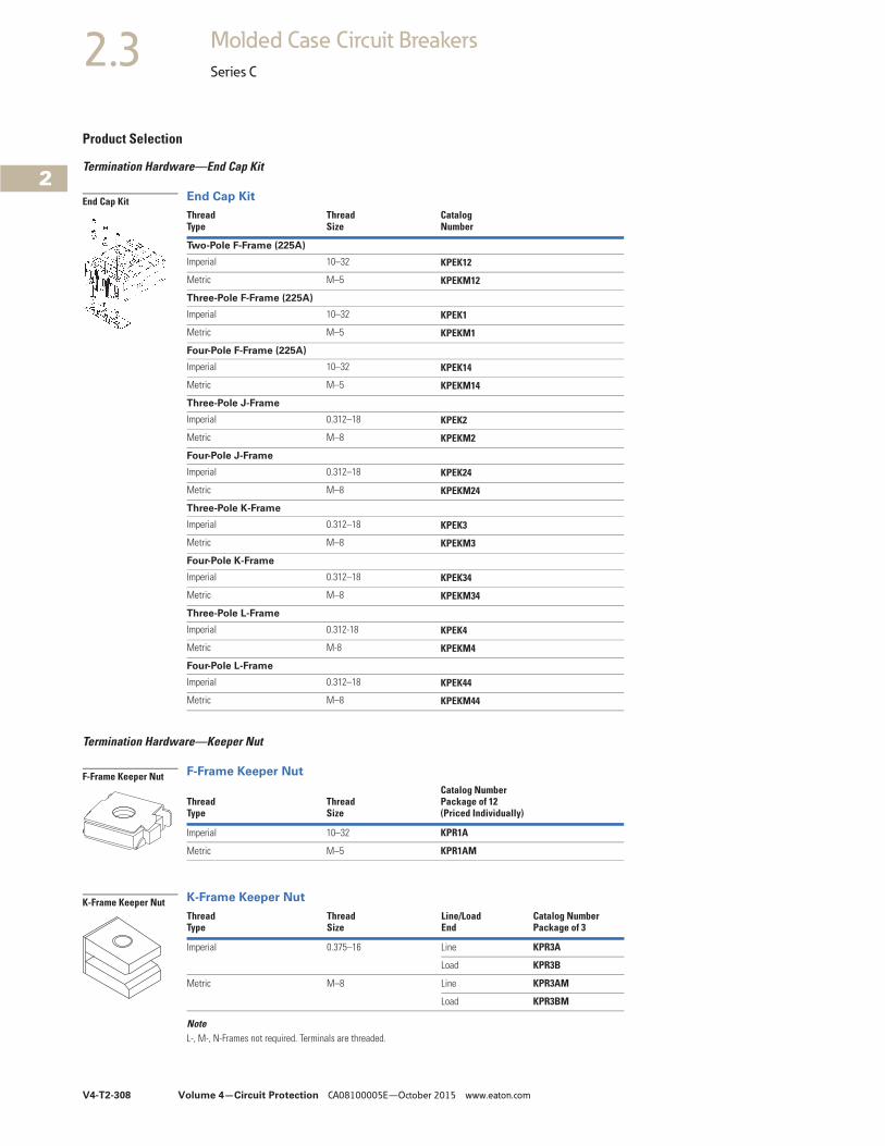
V4-T2-308 Volume 4—Circuit Protection CA08100005E—October 2015 www.eaton.com
2
2
2
2
2
2
2
2
2
2
2
2
2
2
2
2
2
2
2
2
2
2
2
2
2
2
2
2
2
2
2.3 Molded Case Circuit Breakers
Series C
Product Selection
Termination Hardware—End Cap Kit
End Cap Kit
Termination Hardware—Keeper Nut
F-Frame Keeper Nut
K-Frame Keeper Nut
NoteL-, M-, N-Frames not required. Terminals are threaded.
Thread Type
Thread Size
CatalogNumber
Two-Pole F-Frame (225A)
Imperial 10–32 KPEK12
Metric M–5 KPEKM12
Three-Pole F-Frame (225A)
Imperial 10–32 KPEK1
Metric M–5 KPEKM1
Four-Pole F-Frame (225A)
Imperial 10–32 KPEK14
Metric M–5 KPEKM14
Three-Pole J-Frame
Imperial 0.312–18 KPEK2
Metric M–8 KPEKM2
Four-Pole J-Frame
Imperial 0.312–18 KPEK24
Metric M–8 KPEKM24
Three-Pole K-Frame
Imperial 0.312–18 KPEK3
Metric M–8 KPEKM3
Four-Pole K-Frame
Imperial 0.312–18 KPEK34
Metric M–8 KPEKM34
Three-Pole L-Frame
Imperial 0.312-18 KPEK4
Metric M-8 KPEKM4
Four-Pole L-Frame
Imperial 0.312–18 KPEK44
Metric M–8 KPEKM44
ThreadType
ThreadSize
Catalog NumberPackage of 12(Priced Individually)
Imperial 10–32 KPR1A
Metric M–5 KPR1AM
ThreadType
ThreadSize
Line/LoadEnd
Catalog NumberPackage of 3
Imperial 0.375–16 Line KPR3A
Load KPR3B
Metric M–8 Line KPR3AM
Load KPR3BM
End Cap Kit
F-Frame Keeper Nut
K-Frame Keeper Nut

Volume 4—Circuit Protection CA08100005E—October 2015 www.eaton.com V4-T2-309
2
2
2
2
2
2
2
2
2
2
2
2
2
2
2
2
2
2
2
2
2
2
2
2
2
2
2
2
2
2
2.3Molded Case Circuit Breakers
Series C
Termination Hardware
J-Frame Plug Nut
K-Frame Terminal Adapter 1
F-Frame Ordering InformationTerminals must be ordered separately. Priced individually.
F-Frame Control Wire Terminal Kit 2
J- and K-Frame Ordering InformationTerminals must be ordered separately. Priced individually.
J- and K-Frame Control Wire Terminal Kit
L-Frame Control Wire Terminal Kit
Notes1 K-Frame terminal adapter for use in replacing LB/DA breakers.2 Not for use with T250KB terminals.3 Individually packed.4 Terminal kits contain one terminal for each pole and one terminal cover.5 Two-pole kit.6 Three-pole kit.7 Four-pole kit.
ThreadType
ThreadSize
Catalog NumberPackage of 6
Imperial 0.250–20 PLN2
Metric M–6 PLN2M
Line/Load EndCatalogNumber
Line and load TAD3
DescriptionMaximumAmperes
CatalogNumber
Package of 12 control wire terminal tangs. 150 FCWTK
225 FCWTK225
DescriptionCatalogNumber
Package of 12 control wire terminal tangs. KCWTK
AWG WireRange/Number Conductors
Metric WireRange mm2
CatalogNumber
Al/Cu 3/0–350 kcmil (2)
95–150 TA602LDCW 3
Cu 250–350 kcmil (2)
120–250 T602LDCW 3
Al/Cu 400–500 kcmil (2)
185–240 2TA603LDKCW 45
Al/Cu 400–500 kcmil (2)
185–240 3TA603LDKCW 46
Al/Cu 400–500 kcmil (2)
185–240 4TA603LDKCW 47
J-Frame Plug Nut
K-Frame Terminal Adapter
F-Frame Kit
J- and K-Frame Kit
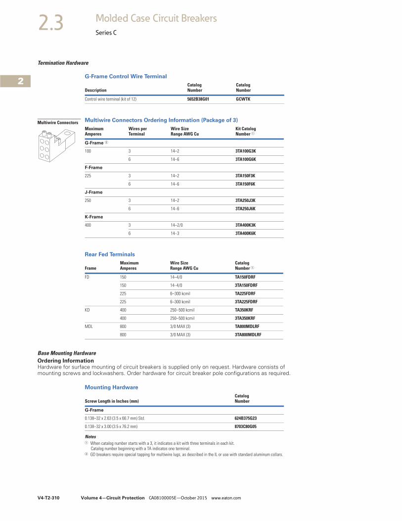
V4-T2-310 Volume 4—Circuit Protection CA08100005E—October 2015 www.eaton.com
2
2
2
2
2
2
2
2
2
2
2
2
2
2
2
2
2
2
2
2
2
2
2
2
2
2
2
2
2
2
2.3 Molded Case Circuit Breakers
Series C
Termination Hardware
G-Frame Control Wire Terminal
Multiwire Connectors Ordering Information (Package of 3)
Rear Fed Terminals
Base Mounting Hardware Ordering InformationHardware for surface mounting of circuit breakers is supplied only on request. Hardware consists of mounting screws and lockwashers. Order hardware for circuit breaker pole configurations as required.
Mounting Hardware
Notes1 When catalog number starts with a 3, it indicates a kit with three terminals in each kit.
Catalog number beginning with a TA indicates one terminal.2 GD breakers require special tapping for multiwire lugs, as described in the IL or use with standard aluminum collars.
DescriptionCatalogNumber
CatalogNumber
Control wire terminal (kit of 12) 5652B38G01 GCWTK
MaximumAmperes
Wires perTerminal
Wire SizeRange AWG Cu
Kit CatalogNumber 1
G-Frame 2
100 3 14–2 3TA100G3K
6 14–6 3TA100G6K
F-Frame
225 3 14–2 3TA150F3K
6 14–6 3TA150F6K
J-Frame
250 3 14–2 3TA250J3K
6 14–6 3TA250J6K
K-Frame
400 3 14–2/0 3TA400K3K
6 14–3 3TA400K6K
FrameMaximumAmperes
Wire SizeRange AWG Cu
CatalogNumber 1
FD 150 14–4/0 TA150FDRF
150 14–4/0 3TA150FDRF
225 6–300 kcmil TA225FDRF
225 6–300 kcmil 3TA225FDRF
KD 400 250–500 kcmil TA350KRF
400 250–500 kcmil 3TA350KRF
MDL 800 3/0 MAX (3) TA800MDLRF
800 3/0 MAX (3) 3TA800MDLRF
Screw Length in Inches (mm)CatalogNumber
G-Frame
0.138–32 x 2.63 (3.5 x 66.7 mm) Std. 624B375G23
0.138–32 x 3.00 (3.5 x 76.2 mm) 8703C80G05
Multiwire Connectors
Volume 4—Circuit Protection CA08100005E—October 2015 www.eaton.com V4-T2-311
2
2
2
2
2
2
2
2
2
2
2
2
2
2
2
2
2
2
2
2
2
2
2
2
2
2
2
2
2
2
2.3Molded Case Circuit Breakers
Series C
Imperial Thread Mounting Hardware
Metric Thread Mounting Hardware
Note1 One set of hardware for two circuit breakers.
Number of Poles Description
Type of Mounting
CatalogNumber
F-Frame
1 0.164-32 x 3.188-inch pan-head steel screws, lockwashers and clamps Individual 624B375G01
Group 1 624B375G02
2 0.164-32 x 1.5-inch pan-head steel screws and lockwashers Individual 4218B80G01
3, 4 0.164-32 x 1.5-inch pan-head steel screws and lockwashers Individual BMH1
J-Frame
2, 3, 4 0.250-20 x 2.75 inch pan-head steel screws and lockwashers Individual BMH2
K-Frame
2, 3, 4 0.250-20 x 1.5 inch pan-head steel screws and lockwashers Individual BMH3
L-Frame
2, 3, 4 0.250-20 x 1.5 inch filister-head steel screws and lockwashers and flat washers Individual BMH4
M-Frame
2, 3 0.3125-18 x 1.25 inch filister-head steel screws and lockwashers and flat washers Individual BMH5
N-Frame
2, 3, 4 0.3125-18 x 1.25 inch pan-head steel screws and lockwashers Individual BMH5
R-Frame
Supplied by customer
Numberof Poles Description
Type ofMounting
CatalogNumber
F-Frame
1 M4–0.7 x 80 mm pan-head steel screws, lockwashers, and clamps Individual 4218B80G09
Group 1 4218B80G10
2 M4–0.7 x 38 mm pan-head steel screws and lockwashers Individual 4218B80G11
3, 4 M4–0.7 x 38 mm pan-head steel screws and lockwashers Individual BMH1M
J-Frame
2, 3, 4 M6–0.7 x 70 mm pan-head steel screws and lockwashers Individual BMH2M
K-Frame
2, 3, 4 M6–0.7 x 38 mm pan-head steel screws and lockwashers Individual BMH3M
L-Frame
2, 3 — Individual BMH4M
M-Frame
2, 3 — Individual BMH5M
N-Frame
2, 3 — Individual BMH5M
R-Frame
Supplied by customer
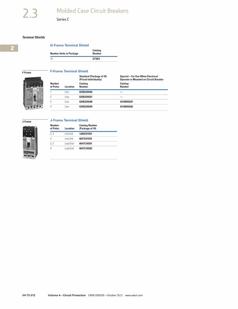
V4-T2-312 Volume 4—Circuit Protection CA08100005E—October 2015 www.eaton.com
2
2
2
2
2
2
2
2
2
2
2
2
2
2
2
2
2
2
2
2
2
2
2
2
2
2
2
2
2
2
2.3 Molded Case Circuit Breakers
Series C
Terminal Shields
G-Frame Terminal Shield
F-Frame Terminal Shield
J-Frame Terminal Shield
Number Units in PackageCatalogNumber
10 GTSK3
Numberof Poles Location
Standard (Package of 10)(Priced Individually)
Special—For Use When ElectricalOperator is Mounted on Circuit Breaker
CatalogNumber
CatalogNumber
1 Line 625B229G06 —
2 Line 625B229G07 —
3 Line 625B229G08 4210B95G01
4 Line 625B229G09 4210B95G02
Number of Poles Location
Catalog Number(Package of 10)
2, 3 Line End 1266C07G01
4 Line End 6631C01G01
2, 3 Load End 6641C16G01
4 Load End 6641C16G02
F-Frame
J-Frame

Volume 4—Circuit Protection CA08100005E—October 2015 www.eaton.com V4-T2-313
2
2
2
2
2
2
2
2
2
2
2
2
2
2
2
2
2
2
2
2
2
2
2
2
2
2
2
2
2
2
2.3Molded Case Circuit Breakers
Series C
K-Frame Terminal Shield
L-Frame Terminal Shield
M-Frame Terminal Shield
N-Frame Terminal Shield
Terminal End Covers Ordering InformationThe terminal end cover is available for three-pole circuit breakers only. Two conductor opening sizes are available. Specify quantity (one per circuit breaker) when ordering.
F-Frame Terminal End Covers
Interphase BarriersOrdering InformationTwo per package.
Interphase Barriers
Base Mounting Plate
Base Mounting Plate G-Frame GD/GHC
DIN Rail Adapter
DIN Rail Adapter G-Frame GD/GHC
All Metal DIN Rail Adapter G-Frame GD/GHC
Key Operated Attachment
Key Operated Attachment G-Frame GD/GHC
Note1 For use on three-pole breakers only.
Numberof Poles Location
Catalog Number(Package of 10)
2, 3 Line TS33LN
4 Line TS34LN
3 Load TS33LD
Catalog Number(Package of 1)
314C420G05
Catalog Number(Package of 1)
208B966G01
Catalog Number(Package of 1)
NTS3K
Conductor OpeningDiameter in Inches (mm)
CatalogNumber
0.25 (6.35 mm) TEC1
0.41 (10.41 mm) TEC2
K-Frame
F-Frame
FrameCatalogNumber
F IPB1
J, K IPB3
L IPB4
M IPB4
N IPB5
Number of Unitsin Package
CatalogNumber
1 207B513G01
Number of Poles
Number of Units in Package
CatalogNumber
1, 2 10 1225C79G01
3 10 1225C79G02 1
Number of Poles
Number of Units in Package
CatalogNumber
3 1 EGGDDIN
Number of Unitsin Package
CatalogNumber
10 GKOA
Interphase Barrier
Base Mounting Plate
DIN Rail Adapter
Key Operated Attachment
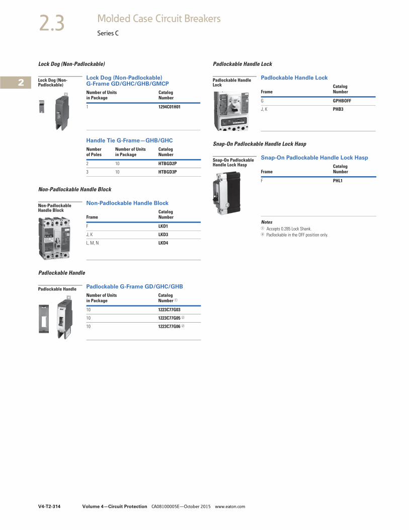
V4-T2-314 Volume 4—Circuit Protection CA08100005E—October 2015 www.eaton.com
2
2
2
2
2
2
2
2
2
2
2
2
2
2
2
2
2
2
2
2
2
2
2
2
2
2
2
2
2
2
2.3 Molded Case Circuit Breakers
Series C
Lock Dog (Non-Padlockable)
Lock Dog (Non-Padlockable) G-Frame GD/GHC/GHB/GMCP
Handle Tie G-Frame—GHB/GHC
Non-Padlockable Handle Block
Non-Padlockable Handle Block
Padlockable Handle
Padlockable G-Frame GD/GHC/GHB
Padlockable Handle Lock
Padlockable Handle Lock
Snap-On Padlockable Handle Lock Hasp
Snap-On Padlockable Handle Lock Hasp
Notes1 Accepts 0.285 Lock Shank.2 Padlockable in the OFF position only.
Number of Unitsin Package
CatalogNumber
1 1294C01H01
Number of Poles
Number of Units in Package
CatalogNumber
2 10 HTBGD2P
3 10 HTBGD3P
FrameCatalogNumber
F LKD1
J, K LKD3
L, M, N LKD4
Number of Unitsin Package
CatalogNumber 1
10 1223C77G03
10 1223C77G05 2
10 1223C77G06 2
Lock Dog (Non-Padlockable)
Non-Padlockable Handle Block
Padlockable Handle
FrameCatalogNumber
G GPHBOFF
J, K PHB3
FrameCatalogNumber
F PHL1
Padlockable Handle Lock
Snap-On Padlockable Handle Lock Hasp
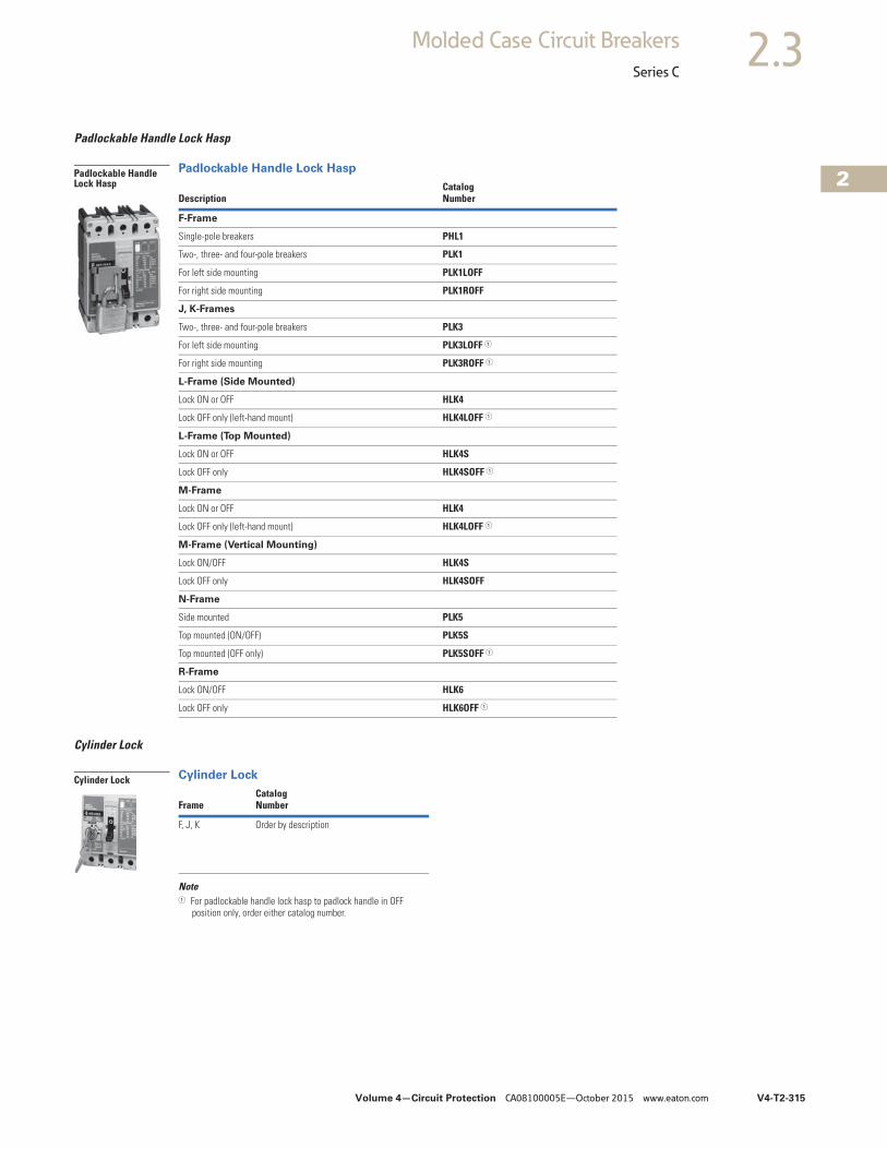
Volume 4—Circuit Protection CA08100005E—October 2015 www.eaton.com V4-T2-315
2
2
2
2
2
2
2
2
2
2
2
2
2
2
2
2
2
2
2
2
2
2
2
2
2
2
2
2
2
2
2.3Molded Case Circuit Breakers
Series C
Padlockable Handle Lock Hasp
Padlockable Handle Lock Hasp
Cylinder Lock
Cylinder Lock
Note1 For padlockable handle lock hasp to padlock handle in OFF
position only, order either catalog number.
DescriptionCatalogNumber
F-Frame
Single-pole breakers PHL1
Two-, three- and four-pole breakers PLK1
For left side mounting PLK1LOFF
For right side mounting PLK1ROFF
J, K-Frames
Two-, three- and four-pole breakers PLK3
For left side mounting PLK3LOFF 1
For right side mounting PLK3ROFF 1
L-Frame (Side Mounted)
Lock ON or OFF HLK4
Lock OFF only (left-hand mount) HLK4LOFF 1
L-Frame (Top Mounted)
Lock ON or OFF HLK4S
Lock OFF only HLK4SOFF 1
M-Frame
Lock ON or OFF HLK4
Lock OFF only (left-hand mount) HLK4LOFF 1
M-Frame (Vertical Mounting)
Lock ON/OFF HLK4S
Lock OFF only HLK4SOFF
N-Frame
Side mounted PLK5
Top mounted (ON/OFF) PLK5S
Top mounted (OFF only) PLK5SOFF 1
R-Frame
Lock ON/OFF HLK6
Lock OFF only HLK6OFF 1
Padlockable Handle Lock Hasp
FrameCatalogNumber
F, J, K Order by description
Cylinder Lock
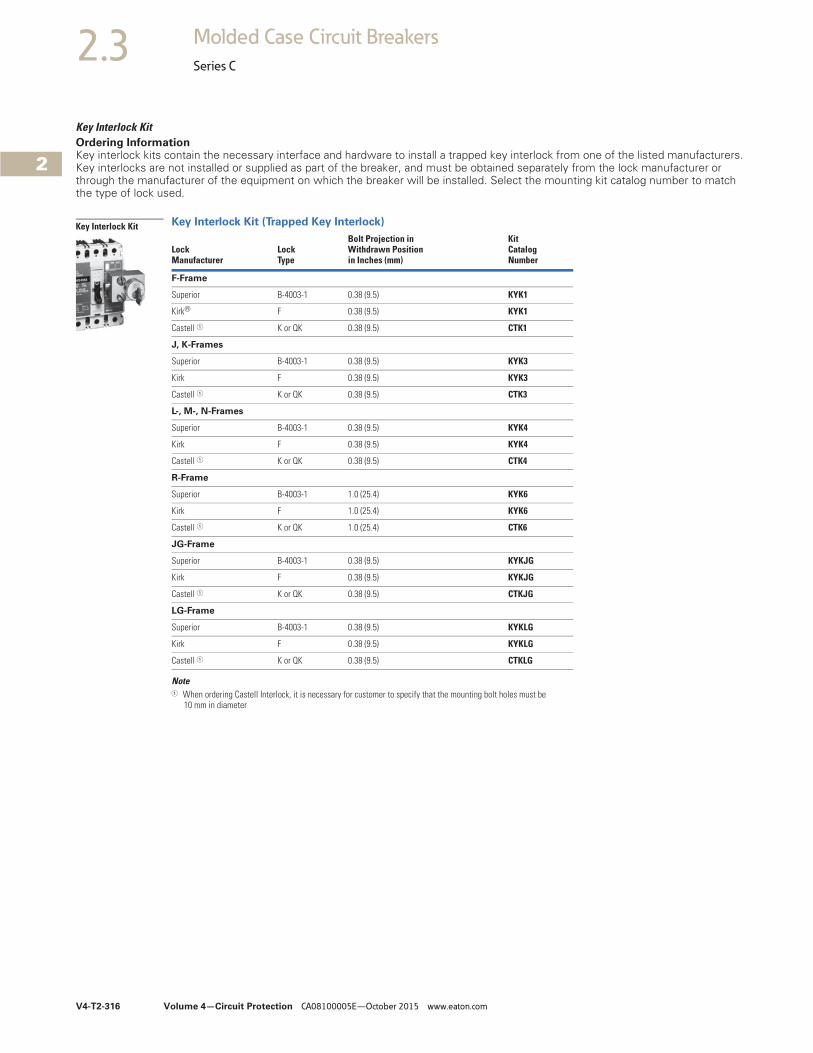
V4-T2-316 Volume 4—Circuit Protection CA08100005E—October 2015 www.eaton.com
2
2
2
2
2
2
2
2
2
2
2
2
2
2
2
2
2
2
2
2
2
2
2
2
2
2
2
2
2
2
2.3 Molded Case Circuit Breakers
Series C
Key Interlock Kit Ordering InformationKey interlock kits contain the necessary interface and hardware to install a trapped key interlock from one of the listed manufacturers. Key interlocks are not installed or supplied as part of the breaker, and must be obtained separately from the lock manufacturer or through the manufacturer of the equipment on which the breaker will be installed. Select the mounting kit catalog number to match the type of lock used.
Key Interlock Kit (Trapped Key Interlock)
Note1 When ordering Castell Interlock, it is necessary for customer to specify that the mounting bolt holes must be
10 mm in diameter
Lock Manufacturer
Lock Type
Bolt Projection in Withdrawn Position in Inches (mm)
KitCatalog Number
F-Frame
Superior B-4003-1 0.38 (9.5) KYK1
Kirk® F 0.38 (9.5) KYK1
Castell 1 K or QK 0.38 (9.5) CTK1
J, K-Frames
Superior B-4003-1 0.38 (9.5) KYK3
Kirk F 0.38 (9.5) KYK3
Castell 1 K or QK 0.38 (9.5) CTK3
L-, M-, N-Frames
Superior B-4003-1 0.38 (9.5) KYK4
Kirk F 0.38 (9.5) KYK4
Castell 1 K or QK 0.38 (9.5) CTK4
R-Frame
Superior B-4003-1 1.0 (25.4) KYK6
Kirk F 1.0 (25.4) KYK6
Castell 1 K or QK 1.0 (25.4) CTK6
JG-Frame
Superior B-4003-1 0.38 (9.5) KYKJG
Kirk F 0.38 (9.5) KYKJG
Castell 1 K or QK 0.38 (9.5) CTKJG
LG-Frame
Superior B-4003-1 0.38 (9.5) KYKLG
Kirk F 0.38 (9.5) KYKLG
Castell 1 K or QK 0.38 (9.5) CTKLG
photo
position
Key Interlock Kit
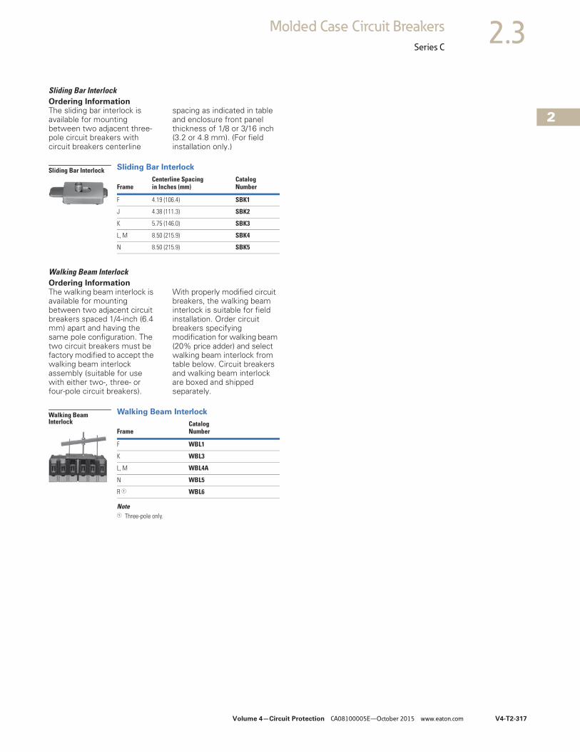
Volume 4—Circuit Protection CA08100005E—October 2015 www.eaton.com V4-T2-317
2
2
2
2
2
2
2
2
2
2
2
2
2
2
2
2
2
2
2
2
2
2
2
2
2
2
2
2
2
2
2.3Molded Case Circuit Breakers
Series C
Sliding Bar Interlock Ordering InformationThe sliding bar interlock is available for mounting between two adjacent three-pole circuit breakers with circuit breakers centerline
spacing as indicated in table and enclosure front panel thickness of 1/8 or 3/16 inch (3.2 or 4.8 mm). (For field installation only.)
Sliding Bar Interlock
Walking Beam Interlock Ordering InformationThe walking beam interlock is available for mounting between two adjacent circuit breakers spaced 1/4-inch (6.4 mm) apart and having the same pole configuration. The two circuit breakers must be factory modified to accept the walking beam interlock assembly (suitable for use with either two-, three- or four-pole circuit breakers).
With properly modified circuit breakers, the walking beam interlock is suitable for field installation. Order circuit breakers specifying modification for walking beam (20% price adder) and select walking beam interlock from table below. Circuit breakers and walking beam interlock are boxed and shipped separately.
Walking Beam Interlock
Note1 Three-pole only.
FrameCenterline Spacingin Inches (mm)
CatalogNumber
F 4.19 (106.4) SBK1
J 4.38 (111.3) SBK2
K 5.75 (146.0) SBK3
L, M 8.50 (215.9) SBK4
N 8.50 (215.9) SBK5
Sliding Bar Interlock
FrameCatalogNumber
F WBL1
K WBL3
L, M WBL4A
N WBL5
R 1 WBL6
Walking Beam Interlock
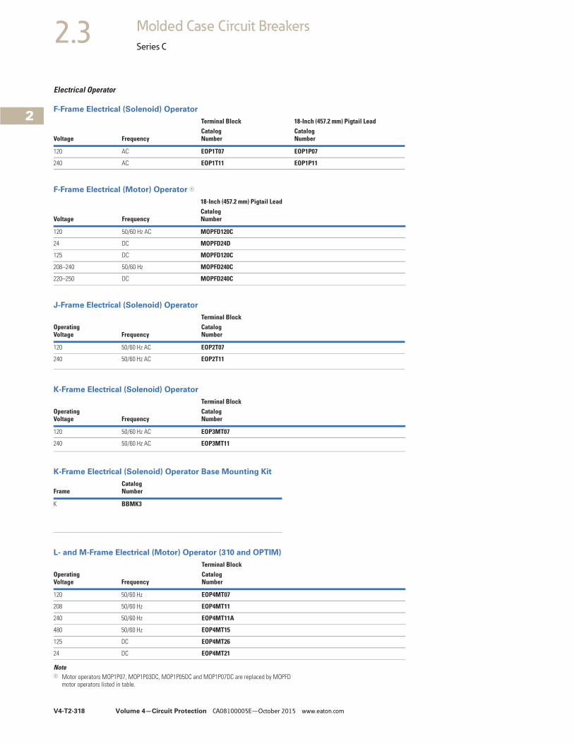
V4-T2-318 Volume 4—Circuit Protection CA08100005E—October 2015 www.eaton.com
2
2
2
2
2
2
2
2
2
2
2
2
2
2
2
2
2
2
2
2
2
2
2
2
2
2
2
2
2
2
2.3 Molded Case Circuit Breakers
Series C
Electrical Operator
F-Frame Electrical (Solenoid) Operator
F-Frame Electrical (Motor) Operator 1
J-Frame Electrical (Solenoid) Operator
K-Frame Electrical (Solenoid) Operator
K-Frame Electrical (Solenoid) Operator Base Mounting Kit
L- and M-Frame Electrical (Motor) Operator (310 and OPTIM)
Note1 Motor operators MOP1P07, MOP1P03DC, MOP1P05DC and MOP1P07DC are replaced by MOPFD
motor operators listed in table.
Voltage Frequency
Terminal Block 18-Inch (457.2 mm) Pigtail LeadCatalogNumber
CatalogNumber
120 AC EOP1T07 EOP1P07
240 AC EOP1T11 EOP1P11
Voltage Frequency
18-Inch (457.2 mm) Pigtail LeadCatalogNumber
120 50/60 Hz AC MOPFD120C
24 DC MOPFD24D
125 DC MOPFD120C
208–240 50/60 Hz MOPFD240C
220–250 DC MOPFD240C
OperatingVoltage Frequency
Terminal BlockCatalogNumber
120 50/60 Hz AC EOP2T07
240 50/60 Hz AC EOP2T11
OperatingVoltage Frequency
Terminal BlockCatalogNumber
120 50/60 Hz AC EOP3MT07
240 50/60 Hz AC EOP3MT11
FrameCatalog Number
K BBMK3
OperatingVoltage Frequency
Terminal BlockCatalogNumber
120 50/60 Hz EOP4MT07
208 50/60 Hz EOP4MT11
240 50/60 Hz EOP4MT11A
480 50/60 Hz EOP4MT15
125 DC EOP4MT26
24 DC EOP4MT21
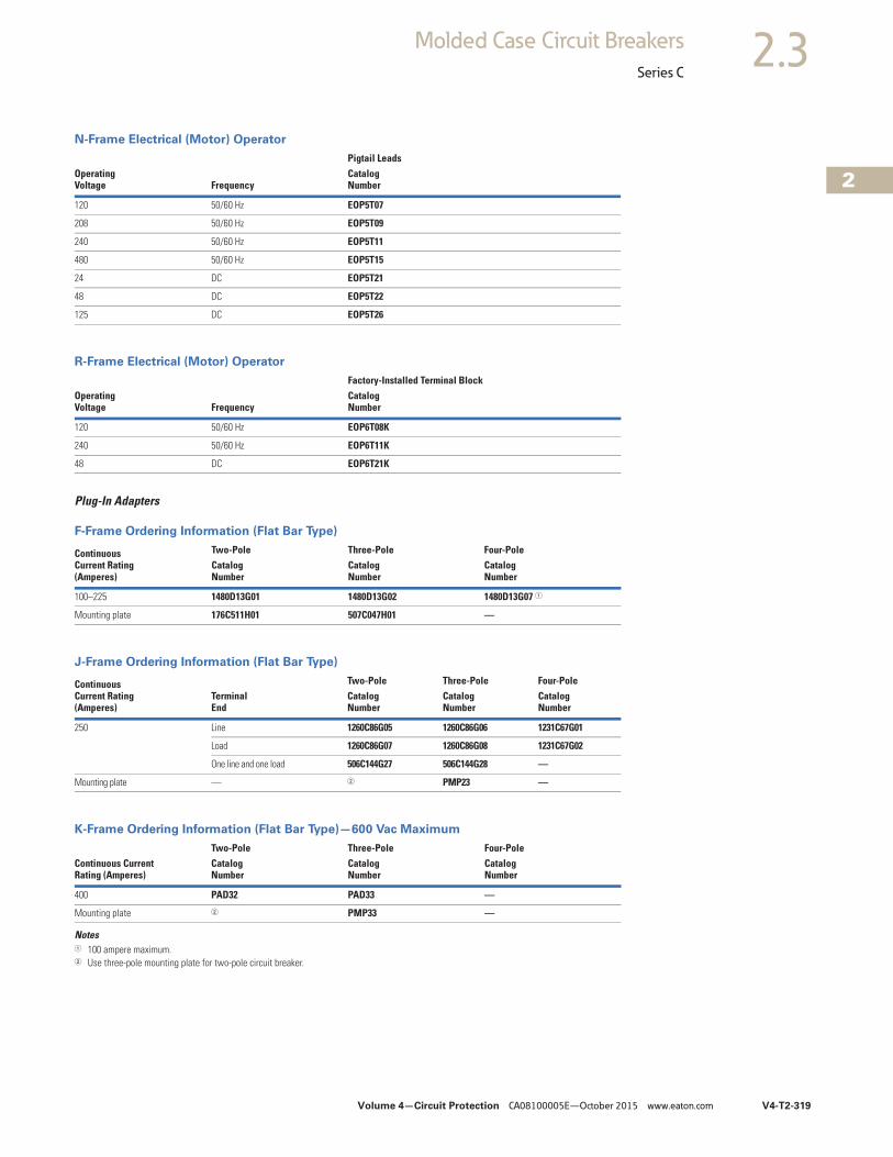
Volume 4—Circuit Protection CA08100005E—October 2015 www.eaton.com V4-T2-319
2
2
2
2
2
2
2
2
2
2
2
2
2
2
2
2
2
2
2
2
2
2
2
2
2
2
2
2
2
2
2.3Molded Case Circuit Breakers
Series C
N-Frame Electrical (Motor) Operator
R-Frame Electrical (Motor) Operator
Plug-In Adapters
F-Frame Ordering Information (Flat Bar Type)
J-Frame Ordering Information (Flat Bar Type)
K-Frame Ordering Information (Flat Bar Type)—600 Vac Maximum
Notes1 100 ampere maximum.2 Use three-pole mounting plate for two-pole circuit breaker.
Operating Voltage Frequency
Pigtail LeadsCatalogNumber
120 50/60 Hz EOP5T07
208 50/60 Hz EOP5T09
240 50/60 Hz EOP5T11
480 50/60 Hz EOP5T15
24 DC EOP5T21
48 DC EOP5T22
125 DC EOP5T26
OperatingVoltage Frequency
Factory-Installed Terminal BlockCatalogNumber
120 50/60 Hz EOP6T08K
240 50/60 Hz EOP6T11K
48 DC EOP6T21K
ContinuousCurrent Rating (Amperes)
Two-Pole Three-Pole Four-PoleCatalogNumber
CatalogNumber
CatalogNumber
100–225 1480D13G01 1480D13G02 1480D13G07 1
Mounting plate 176C511H01 507C047H01 —
ContinuousCurrent Rating(Amperes)
TerminalEnd
Two-Pole Three-Pole Four-PoleCatalogNumber
CatalogNumber
Catalog Number
250 Line 1260C86G05 1260C86G06 1231C67G01
Load 1260C86G07 1260C86G08 1231C67G02
One line and one load 506C144G27 506C144G28 —
Mounting plate — 2 PMP23 —
Continuous CurrentRating (Amperes)
Two-Pole Three-Pole Four-PoleCatalogNumber
CatalogNumber
CatalogNumber
400 PAD32 PAD33 —
Mounting plate 2 PMP33 —
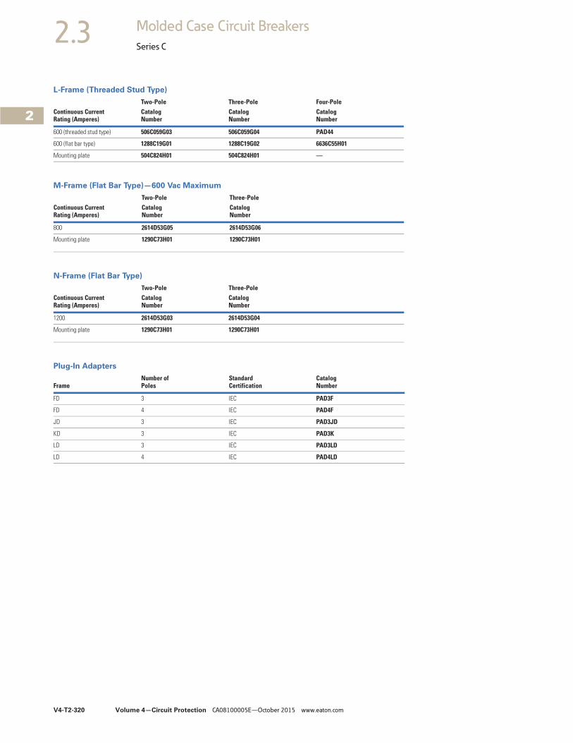
V4-T2-320 Volume 4—Circuit Protection CA08100005E—October 2015 www.eaton.com
2
2
2
2
2
2
2
2
2
2
2
2
2
2
2
2
2
2
2
2
2
2
2
2
2
2
2
2
2
2
2.3 Molded Case Circuit Breakers
Series C
L-Frame (Threaded Stud Type)
M-Frame (Flat Bar Type)—600 Vac Maximum
N-Frame (Flat Bar Type)
Plug-In Adapters
Continuous CurrentRating (Amperes)
Two-Pole Three-Pole Four-PoleCatalogNumber
CatalogNumber
CatalogNumber
600 (threaded stud type) 506C059G03 506C059G04 PAD44
600 (flat bar type) 1288C19G01 1288C19G02 6636C55H01
Mounting plate 504C824H01 504C824H01 —
Continuous CurrentRating (Amperes)
Two-Pole Three-PoleCatalog Number
Catalog Number
800 2614D53G05 2614D53G06
Mounting plate 1290C73H01 1290C73H01
Continuous CurrentRating (Amperes)
Two-Pole Three-PoleCatalog Number
Catalog Number
1200 2614D53G03 2614D53G04
Mounting plate 1290C73H01 1290C73H01
FrameNumber of Poles
Standard Certification
Catalog Number
FD 3 IEC PAD3F
FD 4 IEC PAD4F
JD 3 IEC PAD3JD
KD 3 IEC PAD3K
LD 3 IEC PAD3LD
LD 4 IEC PAD4LD
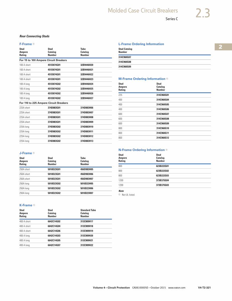
Volume 4—Circuit Protection CA08100005E—October 2015 www.eaton.com V4-T2-321
2
2
2
2
2
2
2
2
2
2
2
2
2
2
2
2
2
2
2
2
2
2
2
2
2
2
2
2
2
2
2.3Molded Case Circuit Breakers
Series C
Rear Connecting Studs
F-Frame 1
J-Frame 1
K-Frame 1
L-Frame Ordering Information
M-Frame Ordering Information 1
N-Frame Ordering Information 1
Note1 Not UL listed.
Stud AmpereRating
Stud CatalogNumber
Tube CatalogNumber
For 15 to 100 Ampere Circuit Breakers
100 A short 451D874G01 32B9446H20
100 A short 451D874G01 32B9446H21
100 A short 451D874G01 32B9446H22
100 A short 451D874G01 32B9446H23
100 A long 451D874G02 32B9446H24
100 A long 451D874G02 32B9446H25
100 A long 451D874G02 32B9446H26
100 A long 451D874G02 32B9446H27
For 110 to 225 Ampere Circuit Breakers
225A short 374D883G01 374D883H06
225A short 374D883G01 374D883H07
225A short 374D883G01 374D883H08
225A short 374D883G01 374D883H09
225A long 374D883G02 374D883H10
225A long 374D883G02 374D883H11
225A long 374D883G02 374D883H12
225A long 374D883G02 374D883H13
StudAmpereRating
StudCatalogNumber
TubeCatalogNumber
250A short 5010D23G01 456D983H05
250A short 5010D23G01 456D983H06
250A short 5010D23G01 456D983H07
250A long 5010D23G02 5010D23H05
250A long 5010D23G02 5010D23H06
250A long 5010D23G02 5010D23H07
StudAmpereRating
StudCatalogNumber
Standard TubeCatalogNumber
400 A short 6642C14G02 313C909H17
400 A short 6642C14G04 313C909H18
400 A short 6642C14G06 313C909H19
400 A long 6642C14G03 313C909H20
400 A long 6642C14G05 313C909H21
400 A long 6642C14G07 313C909H22
Stud CatalogNumber
314C960G07
314C960G08
314C960G09
StudAmpereRating
StudCatalogNumber
225 314C960G01
400 314C960G04
400 314C960G05
400 314C960G06
600 314C960G07
600 314C960G08
600 314C960G09
800 314C960G10
800 314C960G11
800 314C960G12
StudAmpereRating
StudCatalogNumber
800 623B222G01
800 623B222G02
800 623B222G03
1200 373B375G04
1200 373B375G03
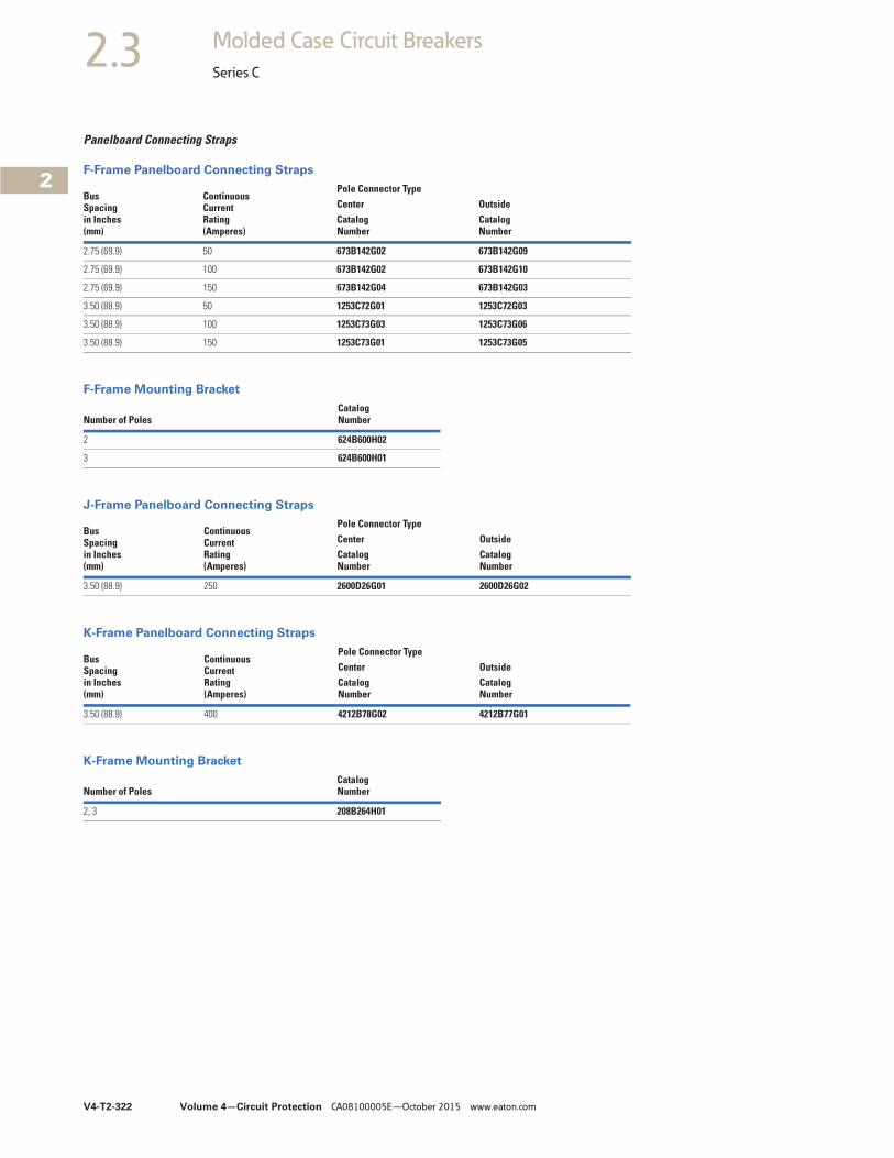
V4-T2-322 Volume 4—Circuit Protection CA08100005E—October 2015 www.eaton.com
2
2
2
2
2
2
2
2
2
2
2
2
2
2
2
2
2
2
2
2
2
2
2
2
2
2
2
2
2
2
2.3 Molded Case Circuit Breakers
Series C
Panelboard Connecting Straps
F-Frame Panelboard Connecting Straps
F-Frame Mounting Bracket
J-Frame Panelboard Connecting Straps
K-Frame Panelboard Connecting Straps
K-Frame Mounting Bracket
BusSpacingin Inches(mm)
ContinuousCurrentRating(Amperes)
Pole Connector TypeCenter OutsideCatalogNumber
CatalogNumber
2.75 (69.9) 50 673B142G02 673B142G09
2.75 (69.9) 100 673B142G02 673B142G10
2.75 (69.9) 150 673B142G04 673B142G03
3.50 (88.9) 50 1253C72G01 1253C72G03
3.50 (88.9) 100 1253C73G03 1253C73G06
3.50 (88.9) 150 1253C73G01 1253C73G05
Number of PolesCatalogNumber
2 624B600H02
3 624B600H01
BusSpacingin Inches(mm)
ContinuousCurrentRating(Amperes)
Pole Connector TypeCenter OutsideCatalogNumber
CatalogNumber
3.50 (88.9) 250 2600D26G01 2600D26G02
BusSpacingin Inches(mm)
ContinuousCurrentRating(Amperes)
Pole Connector TypeCenter OutsideCatalogNumber
CatalogNumber
3.50 (88.9) 400 4212B78G02 4212B77G01
Number of PolesCatalogNumber
2, 3 208B264H01
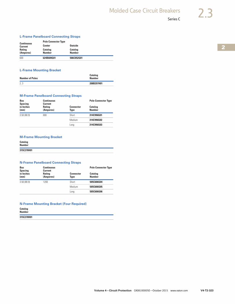
Volume 4—Circuit Protection CA08100005E—October 2015 www.eaton.com V4-T2-323
2
2
2
2
2
2
2
2
2
2
2
2
2
2
2
2
2
2
2
2
2
2
2
2
2
2
2
2
2
2
2.3Molded Case Circuit Breakers
Series C
L-Frame Panelboard Connecting Straps
L-Frame Mounting Bracket
M-Frame Panelboard Connecting Straps
M-Frame Mounting Bracket
N-Frame Panelboard Connecting Straps
N-Frame Mounting Bracket (Four Required)
ContinuousCurrentRating(Amperes)
Pole Connector TypeCenter OutsideCatalogNumber
CatalogNumber
600 624B609G01 506C052G01
Number of PolesCatalogNumber
2, 3 208B297H01
BusSpacingin Inches(mm)
ContinuousCurrentRating(Amperes)
ConnectorType
Pole Connector Type
CatalogNumber
3.50 (88.9) 800 Short 314C996G01
Medium 314C996G02
Long 314C996G03
CatalogNumber
315C270H01
BusSpacingin Inches(mm)
ContinuousCurrentRating(Amperes)
ConnectorType
Pole Connector Type
CatalogNumber
3.50 (88.9) 1200 Short 505C606G04
Medium 505C606G05
Long 505C606G06
CatalogNumber
315C270H01
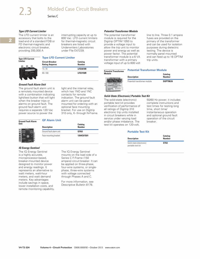
V4-T2-324 Volume 4—Circuit Protection CA08100005E—October 2015 www.eaton.com
2
2
2
2
2
2
2
2
2
2
2
2
2
2
2
2
2
2
2
2
2
2
2
2
2
2
2
2
2
2
2.3 Molded Case Circuit Breakers
Series C
Type LFD Current LimiterThe LFD current limiter is an accessory that bolts to the load end of a standard FDB or FD thermal-magnetic and electronic circuit breaker, providing 200,000 A
interrupting capacity at up to 600 Vac. LFD current limiters for thermal-magnetic circuit breakers are listed with Underwriters Laboratories under File E47239.
Type LFD Current Limiter
Ground Fault Alarm UnitThe ground fault alarm unit is a remotely mounted device with a combination indicating light/test button that will light when the breaker trips or alarms on ground fault. The ground fault alarm unit requires a separate 120 Vac power source to power the
light and the internal relay, which has 1NO and 1NC contacts for remote indication. The ground fault alarm unit can be panel mounted for ordering with an optional face mounting bracket. For use on Digitrip 310 only, K- through N-Frame.
GF Alarm Unit
IQ Energy SentinelThe IQ Energy Sentinel is a highly accurate, microprocessor-based, breaker-mounted device designed to monitor power and energy readings. It represents an alternative to watt meters, watt-hour meters, and watt demand meters. Key advantages include savings in space, lower installation costs, and remote monitoring capability.
The IQ Energy Sentinel mounts on the load side of a Series C F-Frame (150 ampere) circuit breaker. It can be applied on three-phase, four-wire systems, or single-phase, three-wire systems with voltage connected through Phases A and C.
For more information, see Descriptive Bulletin 8178.
Circuit BreakerRating Amperes
CatalogNumber
15–70 LFD3070R
80–160 LFD3150R
Type LFD Current Limiter
DescriptionCatalogNumber
Ground fault alarm unit GFAU
Face mounting bracket 1264C67G01
Ground Fault Alarm Unit
Potential Transformer ModuleThe potential transformer module is required for the Digitrip OPTIM 1050 to provide a voltage input to allow the trip unit to monitor power and energy as well as power factor. The potential transformer module is a 6 VA transformer with a primary voltage input of up to 600 volt
line to line. Three 0.1 ampere fuses are provided on the primary of the transformer and can be used for isolation purposes during dielectric testing. The device is normally panel mounted and can feed up to 16 OPTIM trip units.
Potential Transformer Module
Solid-State (Electronic) Portable Test KitThe solid-state (electronic) portable test kit provides verification of performance of all ratings of Digitrip 310 electronic trip units installed in circuit breakers while in service under varying load and/or phase imbalance. The test kit operates on 120-volt,
50/60 Hz power; it includes complete instructions and test times for testing long time, short time/instantaneous operation and optional ground fault operation of the circuit breaker.
Portable Test Kit
DescriptionCatalogNumber
Potential transformer module DOPTMLN
Potential Transformer Module
DescriptionCatalogNumber
Solid-state (electronic) portable test kit
STK2
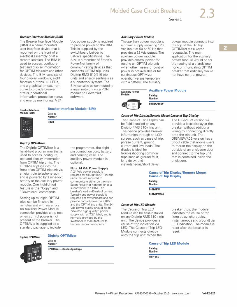
Volume 4—Circuit Protection CA08100005E—October 2015 www.eaton.com V4-T2-325
2
2
2
2
2
2
2
2
2
2
2
2
2
2
2
2
2
2
2
2
2
2
2
2
2
2
2
2
2
2
2.3Molded Case Circuit Breakers
Series C
Breaker Interface Module (BIM) The Breaker Interface Module (BIM) is a panel mounted user interface device that is mounted on the front of an electrical assembly or at a remote location. The BIM is used to access, configure, test and display information for OPTIM trip units and other devices. The BIM consists of four display windows, eight function buttons, 18 LEDs, and a graphical time/current curve to provide breaker status, operational information, protection status and energy monitoring. A 24
Vdc power supply is required to provide power to the BIM. This is supplied by the switchboard builder to Eaton’s specifications. The BIM is a member of Eaton’s PowerNet family of communicating devices that connects OPTIM trip units, Digitrip RMS 810/910 trip units and energy sentinels as a subnetwork system. The BIM can also be connected to a main network via a PONI module to PowerNet software.
Breaker Interface Module (BIM)
Digitrip OPTIMizer The Digitrip OPTIMizer is a hand-held programmer that is used to access, configure, test and display information from OPTIM trip units. The OPTIMizer plugs into the front of an OPTIM trip unit via an eight-pin telephone jack and is powered by a nine-volt battery or the auxiliary power module. One highlighted feature is the “Copy” and “Download” commands.
Setting up multiple OPTIM trips can be finished in minutes and with no errors. An Auxiliary Power Module connection provides a trip test when control power is not present at the breaker. The OPTIMizer is supplied as a standard package to include
the programmer, the eight-pin connection cord, battery and carrying case. The auxiliary power module is optional.
Note: 24 Vdc Power Supply A 24 Vdc power supply is required for all Digitrip OPTIM trip units that are required to communicate either on the main Eaton PowerNet network or as a subnetwork to a BIM. The breaker’s load is 45 mA of current. Typically one power supply is required per switchboard and can provide control power to a BIM and the OPTIM trip units. The 24 Vdc power supply should be an “isolated high quality” power supply with a “CE” label, and is normally provided by the switchboard manufacturer to Eaton’s recommendations.
Digitrip OPTIMizer
CatalogNumber
BIMII
Breaker Interface Module (BIM)
CatalogNumber
OPTIMizer—standard package
Digitrip OPTIMizer
Auxiliary Power Module The auxiliary power module is a power supply requiring 120 Vac input at 50 or 60 Hz that provides a 32 Vdc output. The auxiliary power module provides control power for testing an OPTIM trip unit when other means of control power is not available or for continuous OPTIMizer operation versus temporary with a battery. The auxiliary
power module connects into the top of the Digitrip OPTIMizer via a keyed receptacle. The main application for the auxiliary power module would be for the testing of a standalone non-communicating OPTIM breaker that ordinarily would not have control power.
Auxiliary Power Module
Cause of Trip Display/Remote Mount Cause of Trip DisplayThe Cause of Trip Display can be field-installed on any Digitrip RMS 310+ trip unit. The device provides breaker information through an LCD screen, such as cause of trip, phrase current, ground current and low loads. The display is ideal for troubleshooting common trips such as ground fault, long delay, and instantaneous/short delay.
The DIGIVIEW version will provide a local display at the breaker without additional wiring by connecting directly onto the trip unit. The DIGIVIEWR06 version has a 6 foot cable that allows users to mount the display on the outside of an enclosure door and connect to the trip unit that is contained inside the enclosure.
Cause of Trip Display/Remote Mount Cause of Trip Display
Cause of Trip LED ModuleThe Cause of Trip LED Module can be field-installed on any Digitrip RMS 310+ trip unit. The device provides a cause of trip indication via LED. The Cause of Trip LED Module connects directly onto the trip unit. When the
breaker trips, the module indicates the cause of trip (long delay, short delay, instantaneous and ground) via LED indication. The module is reset after the breaker is reset.
Cause of Trip LED Module
CatalogNumber
PRTBAPMDV
Auxiliary Power Module
CatalogNumber
DIGIVIEW
DIGIVIEWR06
CatalogNumber
TRIP-LED
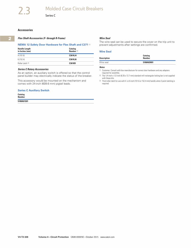
V4-T2-326 Volume 4—Circuit Protection CA08100005E—October 2015 www.eaton.com
2
2
2
2
2
2
2
2
2
2
2
2
2
2
2
2
2
2
2
2
2
2
2
2
2
2
2
2
2
2
2.3 Molded Case Circuit Breakers
Series C
Accessories
Flex Shaft Accessories (F- through R-Frame)
NEMA 12 Safety Door Hardware for Flex Shaft and C371 1
Series C Rotary AccessoriesAs an option, an auxiliary switch is offered so that the control panel builder may electrically indicate the status of the breaker.
This accessory would be mounted on the mechanism and comes with 24-inch (609.6 mm) pigtail leads.
Series C Auxiliary Switch
Handle Lengthin Inches (mm)
CatalogNumber 2
4 (101.6) C361KJ4
6 (152.4) C361KJ6
Roller Latch 3 C361KR
CatalogNumber
5108A61G01
Wire SealThe wire seal can be used to secure the cover on the trip unit to prevent adjustments after settings are confirmed.
Wire Seal
Notes1 Customer: Consult with box manufacturer for correct door hardware and any adapters
required for assembly.2 The 1/4-inch x 1/2-inch (6.35 x 12.7 mm) standard mill rectangular locking bar is not supplied
with these kits.3 Third roller latch for use with 4- or 6-inch (101.6 or 152.4 mm) handle when 3 point latching is
required.
DescriptionCatalog Number
Wire seal 5108A03H01
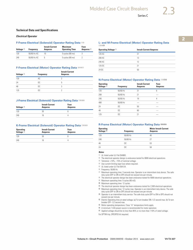
Volume 4—Circuit Protection CA08100005E—October 2015 www.eaton.com V4-T2-327
2
2
2
2
2
2
2
2
2
2
2
2
2
2
2
2
2
2
2
2
2
2
2
2
2
2
2
2
2
2
2.3Molded Case Circuit Breakers
Series C
Technical Data and Specifications
Electrical Operator
F-Frame Electrical (Solenoid) Operator Rating Data 12
F-Frame Electrical (Motor) Operator Rating Data 2567
J-Frame Electrical (Solenoid) Operator Rating Data 1689
K-Frame Electrical (Solenoid) Operator Rating Data 1689
L- and M-Frame Electrical (Motor) Operator Rating Data 168j
N-Frame Electrical (Motor) Operator Rating Data 16kl
R-Frame Electrical (Motor) Operator Rating Data mnop
Notes1 UL listed under UL File E64983.2 The electrical operator design is endurance tested for 8000 electrical operations.3 Tolerance: +10%, –15% of nominal voltage.4 Use current-limiting type fuse where required.5 UL listed under UL File E64124.6 Frequency: 50/60 Hz.7 Maximum operating time: 3 seconds max. Operator is an intermittent duty device. The safe
duty cycle (OFF to ON to OFF) should not exceed one per minute.8 The electrical operator design has been endurance tested for 6000 electrical operations.9 Maximum operating time: 5 cycles (80 mS).j Maximum operating time: 12 cycles.k The electrical operator design has been endurance tested for 2,500 electrical operations.l Maximum operating time: 12 cycles max. Operator is an intermittent duty device. The safe
duty cycle (OFF to ON to OFF) should not exceed one per minute.m Operator is an intermittent duty service. The safe duty cycle (OFF to ON to OFF) should not
exceed one per minute.n Electric Operating time at rated voltage; (a) To turn breaker ON–1/2 second max. (b) To turn
breaker OFF–1/2 second max.o Motor operating temperature; Class “A” temperature limits apply.p A minimum 1 kVA power source is recommended for motor operation.q Applied voltage should be no less than 85% or no more than 110% of rated voltage.
For OPTIM trip, OPEOPCK kit required.
Voltage 3 FrequencyInrush CurrentAmperes
Maximum Operating Time
Fuse Amperes 4
120 50/60 Hz AC 10 5 cycles (80 ms) 3
240 50/60 Hz AC 5 5 cycles (80 ms) 2
Voltage 3 FrequencyInrush CurrentAmperes
120 AC 2
24 DC 5
48 DC 3
125 DC 2
Voltage 3Inrush CurrentAmperes
FuseAmperes
120 30 6
240 16 4
OperatingVoltage 3
Inrush CurrentAmperes
FuseAmperes
120 30 6
240 16 4
Operating Voltage 3 Inrush Current Amperes
120 AC 31
208 AC 13
240 AC 12
125 DC 21
24 DC 50
OperatingVoltage 3 Frequency
Inrush CurrentAmperes
FuseAmperes
120 50/60 Hz 31 6
208 50/60 Hz 21 —
240 50/60 Hz 19 4
480 50/60 Hz — —
24 DC 50 —
48 DC 80 —
125 DC 21 —
OperatingVoltage q Frequency
Motor Inrush CurrentAmperes
120 50/60 Hz 40
240 50/60 Hz 27
48 DC 53
24 DC 58

V4-T2-328 Volume 4—Circuit Protection CA08100005E—October 2015 www.eaton.com
2
2
2
2
2
2
2
2
2
2
2
2
2
2
2
2
2
2
2
2
2
2
2
2
2
2
2
2
2
2
2.3 Molded Case Circuit Breakers
Series C
DimensionsApproximate Dimensions in Inches (mm)
Rear Connecting Studs
F-Frame 1
F-Frame
Note1 Not UL listed.
Stud AmpereRating
Stud CatalogNumber
Panel Thickness Tube Length Tube CatalogNumber
Dimensions
A B C D E F
For 15 to 100 Ampere Circuit Breakers
100 A short 451D874G01 1.00 (25.4) 1.06 (26.9) — 32B9446H20 — 3.63 (92.1) 0.31 (7.9)–18
100 A short 451D874G01 0.69–0.94 (17.5 to 23.8) 1.38 (34.9) — 32B9446H21 — 3.63 (92.1) 0.31 (7.9)–18
100 A short 451D874G01 0.38–0.63 (9.5 to 15.9) 1.69 (42.9) — 32B9446H22 — 3.63 (92.1) 0.31 (7.9)–18
100 A short 451D874G01 0.25–0.31 (6.4 to 7.9) 2.00 (50.8) — 32B9446H23 — 3.63 (92.1) 0.31 (7.9)–18
100 A long 451D874G02 1.00 (25.4) — 3.44 (87.3) 32B9446H24 6.13 (155.6) — 0.31 (7.9)–18
100 A long 451D874G02 0.69–0.94 (17.5 to 23.8) — 3.75 (95.2) 32B9446H25 6.13 (155.6) — 0.31 (7.9)–18
100 A long 451D874G02 0.38–0.63 (9.5 to 15.9) — 4.06 (103.1) 32B9446H26 6.13 (155.6) — 0.31 (7.9)–18
100 A long 451D874G02 0.25–0.31 (6.4 to 7.9) — 4.38 (111.3) 32B9446H27 6.13 (155.6) — 0.31 (7.9)–18
For 110 to 225 Ampere Circuit Breakers
225A short 374D883G01 1.00 (25.4) 1.06 (26.9) — 374D883H06 — 4.25 (108.0) 0.44 (11.1)–14
225A short 374D883G01 0.69–0.94 (17.5 to 23.8) 1.38 (34.9) — 374D883H07 — 4.25 (108.0) 0.44 (11.1)–14
225A short 374D883G01 0.38–0.63 (9.5 to 15.9) 1.69 (42.9) — 374D883H08 — 4.25 (108.0) 0.44 (11.1)–14
225A short 374D883G01 0.25–0.31 (6.4 to 7.9) 2.00 (50.8) — 374D883H09 — 4.25 (108.0) 0.44 (11.1)–14
225A long 374D883G02 1.00 (25.4) — 3.44 (87.3) 374D883H10 7.50 (190.5) — 0.44 (11.1)–14
225A long 374D883G02 0.69–0.94 (17.5 to 23.8) — 3.75 (95.2) 374D883H11 7.50 (190.5) — 0.44 (11.1)–14
225A long 374D883G02 0.38–0.63 (9.5 to 15.9) — 4.06 (103.1) 374D883H12 7.50 (190.5) — 0.44 (11.1)–14
225A long 374D883G02 0.25–0.31 (6.4 to 7.9) — 4.38 (111.3) 374D883H13 7.50 (190.5) — 0.44 (11.1)–14
E
B
A CD
Mounting Panel
Breaker MountingSurface
“F” Thread
.75(19.1)
.06(1.5)
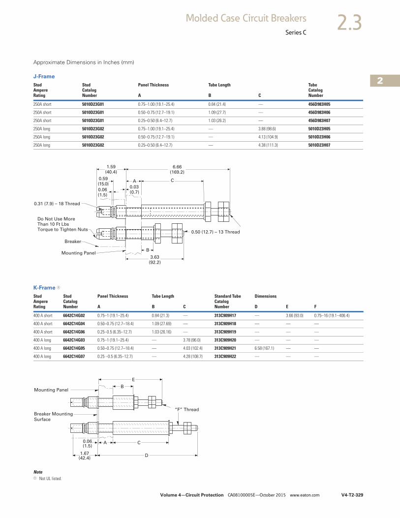
Volume 4—Circuit Protection CA08100005E—October 2015 www.eaton.com V4-T2-329
2
2
2
2
2
2
2
2
2
2
2
2
2
2
2
2
2
2
2
2
2
2
2
2
2
2
2
2
2
2
2.3Molded Case Circuit Breakers
Series C
Approximate Dimensions in Inches (mm)
J-Frame
K-Frame 1
Note1 Not UL listed.
StudAmpereRating
StudCatalogNumber
Panel Thickness Tube Length TubeCatalogNumberA B C
250A short 5010D23G01 0.75–1.00 (19.1–25.4) 0.84 (21.4) — 456D983H05
250A short 5010D23G01 0.50–0.75 (12.7–19.1) 1.09 (27.7) — 456D983H06
250A short 5010D23G01 0.25–0.50 (6.4–12.7) 1.03 (26.2) — 456D983H07
250A long 5010D23G02 0.75–1.00 (19.1–25.4) — 3.88 (98.6) 5010D23H05
250A long 5010D23G02 0.50–0.75 (12.7–19.1) — 4.13 (104.9) 5010D23H06
250A long 5010D23G02 0.25–0.50 (6.4–12.7) — 4.38 (111.3) 5010D23H07
StudAmpereRating
StudCatalogNumber
Panel Thickness Tube Length Standard TubeCatalogNumber
Dimensions
A B C D E F
400 A short 6642C14G02 0.75–1 (19.1–25.4) 0.84 (21.3) — 313C909H17 — 3.66 (93.0) 0.75–16 (19.1–406.4)
400 A short 6642C14G04 0.50–0.75 (12.7–18.4) 1.09 (27.69) — 313C909H18 — — —
400 A short 6642C14G06 0.25–0.5 (6.35–12.7) 1.03 (26.16) — 313C909H19 — — —
400 A long 6642C14G03 0.75–1 (19.1–25.4) — 3.78 (96.0) 313C909H20 — — —
400 A long 6642C14G05 0.50–0.75 (12.7–18.4) — 4.03 (102.4) 313C909H21 6.58 (167.1) — —
400 A long 6642C14G07 0.25 –0.5 (6.35–12.7) — 4.28 (108.7) 313C909H22 — — —
Mounting Panel
Do Not Use MoreThan 10 Ft LbsTorque to Tighten Nuts
CA
0.31 (7.9) – 18 Thread
Breaker
B
6.66(169.2)
0.06(1.5)
0.59(15.0)
1.59(40.4)
0.03(0.7)
0.50 (12.7) – 13 Thread
3.63(92.2)
Mounting Panel
Breaker Mounting
Surface
“F” Thread
CA
D
B
E
0.06(1.5)
1.67(42.4)
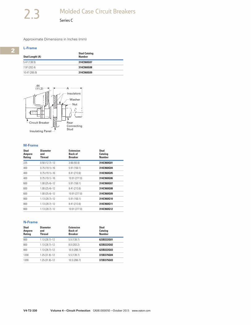
V4-T2-330 Volume 4—Circuit Protection CA08100005E—October 2015 www.eaton.com
2
2
2
2
2
2
2
2
2
2
2
2
2
2
2
2
2
2
2
2
2
2
2
2
2
2
2
2
2
2
2.3 Molded Case Circuit Breakers
Series C
Approximate Dimensions in Inches (mm)
L-Frame
M-Frame
N-Frame
Stud Length (A)Stud CatalogNumber
5.47 (138.9) 314C960G07
7.97 (202.4) 314C960G08
10.47 (265.9) 314C960G09
StudAmpereRating
Diameterand Thread
ExtensionBack of Breaker
StudCatalogNumber
225 0.50 (12.7)–13 3.66 (93.0) 314C960G01
400 0.75 (19.1)–16 5.91 (150.1) 314C960G04
400 0.75 (19.1)–16 8.41 (213.6) 314C960G05
400 0.75 (19.1)–16 10.91 (277.0) 314C960G06
600 1.00 (25.4)–12 5.91 (150.1) 314C960G07
600 1.00 (25.4)–12 8.41 (213.6) 314C960G08
600 1.00 (25.4)–12 10.91 (277.0) 314C960G09
800 1.13 (28.7)–12 5.91 (150.1) 314C960G10
800 1.13 (28.7)–12 8.41 (213.6) 314C960G11
800 1.13 (28.7)–12 10.91 (277.0) 314C960G12
StudAmpereRating
Diameterand Thread
ExtensionBack of Breaker
StudCatalogNumber
800 1.13 (28.7)–12 5.5 (139.7) 623B222G01
800 1.13 (28.7)–12 8.0 (203.2) 623B222G02
800 1.13 (28.7)–12 10.5 (266.7) 623B222G03
1200 1.25 (31.8)–12 5.5 (139.7) 373B375G04
1200 1.25 (31.8)–12 10.5 (266.7) 373B375G03
A
Insulators
Nut
RearConnectingStud
Washer
Insulating Panel
Circuit Breaker
.44(11.2)