230056413 beer-mechanics-of-materials-6th-solutions-chapter-1-pdf
TRANSCRIPT

CCHHAAPPTTEERR 11


PROPRIETARY MATERIAL. © 2012 The McGraw-Hill Companies, Inc. All rights reserved. No part of this Manual may be displayed,
reproduced, or distributed in any form or by any means, without the prior written permission of the publisher, or used beyond the limited
distribution to teachers and educators permitted by McGraw-Hill for their individual course preparation. A student using this manual is using it
without permission.
PROBLEM 1.1
Two solid cylindrical rods AB and BC are welded together at B and loaded as shown. Knowing that the average normal stress must not exceed 175 MPa in rod AB and 150 MPa in rod BC, determine the smallest allowable values of d1 and d2.
SOLUTION
(a) Rod AB
3
2 21 14
33
1 6
40 30 70 kN 70 10 N
4
4 (4)(70 10 )22.6 10 m
(175 10 )
πσπ
πσ π−
= + = = ×
= = =
×= = = ××
ABAB
AB
P
P P P
A d d
Pd 1 22.6 mm=d
(b) Rod BC
3
2 22 24
33
2 6
30 kN 30 10 N
4
4 (4)(30 10 )15.96 10 m
(150 10 )
πσπ
πσ π−
= = ×
= = =
×= = = ××
BCBC
BC
P
P P P
A d d
Pd 2 15.96 mm=d

PROPRIETARY MATERIAL. © 2012 The McGraw-Hill Companies, Inc. All rights reserved. No part of this Manual may be displayed,
reproduced, or distributed in any form or by any means, without the prior written permission of the publisher, or used beyond the limited
distribution to teachers and educators permitted by McGraw-Hill for their individual course preparation. A student using this manual is using it
without permission.
PROBLEM 1.2
Two solid cylindrical rods AB and BC are welded together at B and loaded as shown. Knowing that 1 50=d mm and 2 30=d mm, find the average normal stress at the midsection of (a) rod AB, (b) rod BC.
SOLUTION
(a) Rod AB
3
2 2 3 2 3 21
36
3
40 30 70 kN 70 10 N
(50) 1.9635 10 mm 1.9635 10 m4 4
70 1035.7 10 Pa
1.9635 10
π π
σ
−
−
= + = = ×
= = = × = ×
×= = = ××AB
P
A d
P
A 35.7 MPaσ =AB
(b) Rod BC
3
2 2 2 6 22
36
6
30 kN 30 10 N
(30) 706.86 mm 706.86 10 m4 4
30 1042.4 10 Pa
706.86 10
π π
σ
−
−
= = ×
= = = = ×
×= = = ××BC
P
A d
P
A 42.4 MPaσ =BC

PROPRIETARY MATERIAL. © 2012 The McGraw-Hill Companies, Inc. All rights reserved. No part of this Manual may be displayed,
reproduced, or distributed in any form or by any means, without the prior written permission of the publisher, or used beyond the limited
distribution to teachers and educators permitted by McGraw-Hill for their individual course preparation. A student using this manual is using it
without permission.
PROBLEM 1.3
Two solid cylindrical rods AB and BC are welded together at B and loaded as shown. Determine the magnitude of the force P for which the tensile stress in rod AB is twice the magnitude of the compressive stress in rod BC.
SOLUTION
2 2
2 2
(2) 3.1416 in4
3.1416
0.31831
(3) 7.0686 in4(2)(30)
608.4883 0.14147
7.0686
π
σ
π
σ
= =
= =
=
= =
−=
−= = −
AB
ABAB
BC
BCAB
A
P P
A
P
A
P
A
PP
Equating σ AB to 2σ BC
0.31831 2(8.4883 0.14147 )= −P P 28.2 kips=P

PROPRIETARY MATERIAL. © 2012 The McGraw-Hill Companies, Inc. All rights reserved. No part of this Manual may be displayed,
reproduced, or distributed in any form or by any means, without the prior written permission of the publisher, or used beyond the limited
distribution to teachers and educators permitted by McGraw-Hill for their individual course preparation. A student using this manual is using it
without permission.
PROBLEM 1.4
In Prob. 1.3, knowing that 40=P kips, determine the average normal stress at the midsection of (a) rod AB, (b) rod BC.
PROBLEM 1.3 Two solid cylindrical rods AB and BC are welded together at B and loaded as shown. Determine the magnitude of the force P for which the tensile stress in rod AB is twice the magnitude of the compressive stress in rod BC.
SOLUTION
(a) Rod AB
40 kips (tension)=P
2 22(2)
3.1416 in4 4
40
3.1416
π π
σ
= = =
= =
ABAB
ABAB
dA
P
A 12.73 ksiσ =AB
(b) Rod BC
40 (2)(30) 20 kips, i.e., 20 kips compression.= − = −F
2 22(3)
7.0686 in4 4
20
7.0686
π π
σ
= = =
−= =
BCBC
BCBC
dA
F
A 2.83 ksiσ = −BC

PROPRIETARY MATERIAL. © 2012 The McGraw-Hill Companies, Inc. All rights reserved. No part of this Manual may be displayed,
reproduced, or distributed in any form or by any means, without the prior written permission of the publisher, or used beyond the limited
distribution to teachers and educators permitted by McGraw-Hill for their individual course preparation. A student using this manual is using it
without permission.
PROBLEM 1.5
Two steel plates are to be held together by means of 16-mm-diameter high-strength steel bolts fitting snugly inside cylindrical brass spacers. Knowing that the average normal stress must not exceed 200 MPa in the bolts and 130 MPa in the spacers, determine the outer diameter of the spacers that yields the most economical and safe design.
SOLUTION
At each bolt location the upper plate is pulled down by the tensile force Pb of the bolt. At the same time, the spacer pushes that plate upward with a compressive force Ps in order to maintain equilibrium.
=b sP P
For the bolt, 2
4σπ
= =b bb
b b
F P
A d or 2
4
π σ=b b bP d
For the spacer, 2 2
4
( )σ
π= =
−s s
ss s b
P P
A d d or 2 2( )
4
π σ= −s s s bP d d
Equating bP and ,sP
2 2 2( )4 4
2001 1 (16)
130
b b s s b
bs b
s
d d d
d d
π πσ σ
σσ
= −
= + = +
25.2 mm=sd

PROPRIETARY MATERIAL. © 2012 The McGraw-Hill Companies, Inc. All rights reserved. No part of this Manual may be displayed,
reproduced, or distributed in any form or by any means, without the prior written permission of the publisher, or used beyond the limited
distribution to teachers and educators permitted by McGraw-Hill for their individual course preparation. A student using this manual is using it
without permission.
PROBLEM 1.6
Two brass rods AB and BC, each of uniform diameter, will be brazed together at B to form a nonuniform rod of total length 100 m, which will be suspended from a support at A as shown. Knowing that the density of brass is 8470 kg/m3, determine (a) the length of rod AB for which the maximum normal stress in ABC is minimum, (b) the corresponding value of the maximum normal stress.
SOLUTION
Areas: 2 2 6 2
2 2 6 2
(15 mm) 176.71 mm 176.71 10 m4
(10 mm) 78.54 mm 78.54 10 m4
π
π
−
−
= = = ×
= = = ×
AB
BC
A
A
From geometry, b = 100 − a
Weights: 6
6
(8470)(9.81)(176.71 10 ) 14.683
(8470)(9.81)(78.54 10 )(100 ) 652.59 6.526
ρ
ρ
−
−
= = × =
= = × − = −
AB AB AB
BC BC BC
W g A a a
W g A a a
Normal stresses:
At A,
6 3
652.59 8.157
3.6930 10 46.160 10σ
= + = +
= = × + ×
A AB BC
AA
AB
P W W a
Pa
A
(1)
At B,
6 3
652.59 6.526
8.3090 10 83.090 10σ
= = −
= = × − ×
B BC
BB
BC
P W a
Pa
A
(2)
(a) Length of rod AB. The maximum stress in ABC is minimum when σ σ=A B or
6 34.6160 10 129.25 10 0× − × =a
35.71 m=a 35.7 m= = AB a
(b) Maximum normal stress.
6 3
6 3
6
3.6930 10 (46.160 10 )(35.71)
8.3090 10 (83.090 10 )(35.71)
5.34 10 Pa
σ
σ
σ σ
= × + ×
= × − ×
= = ×
A
B
A B 5.34 MPaσ =

PROPRIETARY MATERIAL. © 2012 The McGraw-Hill Companies, Inc. All rights reserved. No part of this Manual may be displayed,
reproduced, or distributed in any form or by any means, without the prior written permission of the publisher, or used beyond the limited
distribution to teachers and educators permitted by McGraw-Hill for their individual course preparation. A student using this manual is using it
without permission.
PROBLEM 1.7
Each of the four vertical links has an 8 36-mm× uniform rectangular cross section and each of the four pins has a 16-mm diameter. Determine the maximum value of the average normal stress in the links connecting (a) points B and D, (b) points C and E.
SOLUTION
Use bar ABC as a free body.
3
3
3
3
0 : (0.040) (0.025 0.040)(20 10 ) 0
32.5 10 N Link is in tension.
0 : (0.040) (0.025)(20 10 ) 0
12.5 10 N Link is in compression.
C BD
BD
B CE
CE
M F
F BD
M F
F CE
Σ = − + × =
= ×
Σ = − − × =
= − ×
Net area of one link for tension (0.008)(0.036 0.016)= − 6 2160 10 m .−= ×
For two parallel links, 6 2net 320 10 mA −= ×
(a) 3
66
net
32.5 10101.56 10
320 10σ −
×= = = ××
BDBD
F
A 101.6 MPaσ =BD
Area for one link in compression (0.008)(0.036)= 6 2288 10 m .−= ×
For two parallel links, 6 2576 10 m−= ×A
(b) 3
66
12.5 1021.70 10
576 10σ −
−− ×= = = − ×
×CE
CEF
A 21.7 MPaσ = −CE

PROPRIETARY MATERIAL. © 2012 The McGraw-Hill Companies, Inc. All rights reserved. No part of this Manual may be displayed,
reproduced, or distributed in any form or by any means, without the prior written permission of the publisher, or used beyond the limited
distribution to teachers and educators permitted by McGraw-Hill for their individual course preparation. A student using this manual is using it
without permission.
PROBLEM 1.8
Knowing that the link DE is 18
in. thick and 1 in. wide, determine the normal stress in the central portion of that link when (a) 0 ,θ = ° (b) 90 .θ = °
SOLUTION
Use member CEF as a free body.
0 : 12 (8)(60 sin ) (16)(60 cos ) 0
40 sin 80 cos lb.
θ θθ θ
Σ = − − − == − −
C DE
DE
M F
F
21(1) 0.125 in.
8
σ
= =
=
DE
DEDE
DE
A
F
A
(a) 0: 80 lb.DEFθ = = −
80
0.125σ −=DE 640 psiσ = −DE
(b) 90 : 40 lb.DEFθ = ° = −
40
0.125σ −=DE 320 psiσ = −DE

PROPRIETARY MATERIAL. © 2012 The McGraw-Hill Companies, Inc. All rights reserved. No part of this Manual may be displayed,
reproduced, or distributed in any form or by any means, without the prior written permission of the publisher, or used beyond the limited
distribution to teachers and educators permitted by McGraw-Hill for their individual course preparation. A student using this manual is using it
without permission.
PROBLEM 1.9
Link AC has a uniform rectangular cross section 116
in. thick and 1
4 in. wide. Determine the normal stress in the
central portion of the link.
SOLUTION
Free Body Diagram of Plate
Note that the two 240-lb forces form a couple of moment
(240 lb)(6 in.) 1440 lb in.= ⋅
0 : 1440 lb in ( cos 30 )(10 in.) 0
166.277 lb.
Σ = ⋅ − ° ==
B AC
AC
M F
F
Area of link: 21 1 in. in. 0.015625 in.
16 4 = =
ACA
Stress: 166.277
10640 psi0.015625
σ = = =ACAC
AC
F
A 10.64 ksiσ =AC

PROPRIETARY MATERIAL. © 2012 The McGraw-Hill Companies, Inc. All rights reserved. No part of this Manual may be displayed,
reproduced, or distributed in any form or by any means, without the prior written permission of the publisher, or used beyond the limited
distribution to teachers and educators permitted by McGraw-Hill for their individual course preparation. A student using this manual is using it
without permission.
PROBLEM 1.10
Three forces, each of magnitude P = 4 kN, are applied to the mechanism shown. Determine the cross-sectional area of the uniform portion of rod BE for which the normal stress in that portion is +100 MPa.
SOLUTION
Draw free body diagrams of AC and CD.
Free Body CD: 0: 0.150 0.250 0
0.6
Σ = − ==
DM P C
C P
Free Body AC: 0: 0.150 0.350 0.450 0.450 0
1.077.1333 (7.133)(4 kN) 28.533 kN
0.150
= − − − =
= = = =
A BE
BE
M F P P C
F P P
Required area of BE:
36 2
6
28.533 10285.33 10 m
100 10
σ
σ−
=
×= = = ××
BEBE
BE
BEBE
BE
F
A
FA
2285 mm=BEA

PROPRIETARY MATERIAL. © 2012 The McGraw-Hill Companies, Inc. All rights reserved. No part of this Manual may be displayed,
reproduced, or distributed in any form or by any means, without the prior written permission of the publisher, or used beyond the limited
distribution to teachers and educators permitted by McGraw-Hill for their individual course preparation. A student using this manual is using it
without permission.
PROBLEM 1.11
The frame shown consists of four wooden members, ABC, DEF, BE, and CF. Knowing that each member has a 2 × 4-in. rectangular cross section and that each pin has a 1/2-in. diameter, determine the maximum value of the average normal stress (a) in member BE, (b) in member CF.
SOLUTION
Stress in tension member CF
Add support reactions to figure as shown.
Using entire frame as free body,
0: 40 (45 30)(480) 0
900 lb.A x
x
M D
D
Σ = − + ==
Use member DEF as free body.
Reaction at D must be parallel to BEF and .CFF
4
1200 lb.3y xD D= =
40: (30) (30 15) 0
5
2250 lb.
40: (30) (15) 0
5
750 lb.
Σ = − − + =
= −
Σ = − =
=
F BE Y
BE
E CE Y
CE
M F D
F
M F D
F
Stress in compression member BE
Area: 22 in 4 in 8 in= × =A
(a) 2250
8σ −= =BE
BEF
A 281 psiσ = −BE
Minimum section area occurs at pin.
2min (2)(4.0 0.5) 7.0 in= − =A
(b) min
750
7.0σ = =CF
CFF
A 107.1 psiσ =CF

PROPRIETARY MATERIAL. © 2012 The McGraw-Hill Companies, Inc. All rights reserved. No part of this Manual may be displayed,
reproduced, or distributed in any form or by any means, without the prior written permission of the publisher, or used beyond the limited
distribution to teachers and educators permitted by McGraw-Hill for their individual course preparation. A student using this manual is using it
without permission.
PROBLEM 1.12
For the Pratt bridge truss and loading shown, determine the average normal stress in member BE, knowing that the cross-sectional area of that member is 5.87 in2.
SOLUTION
Use entire truss as free body.
0: (9)(80) (18)(80) (27)(80) 36 0
120 kips
H y
y
M A
A
Σ = + + − =
=
Use portion of truss to the left of a section cutting members BD, BE, and CE.
120: 120 80 0 50 kips
15y BE BEF F F+ Σ = − − = ∴ =↑
2
50 kips
5.87 inσ = =BE
BEF
A
8.52 ksiσ =BE

PROPRIETARY MATERIAL. © 2012 The McGraw-Hill Companies, Inc. All rights reserved. No part of this Manual may be displayed,
reproduced, or distributed in any form or by any means, without the prior written permission of the publisher, or used beyond the limited
distribution to teachers and educators permitted by McGraw-Hill for their individual course preparation. A student using this manual is using it
without permission.
PROBLEM 1.13
An aircraft tow bar is positioned by means of a single hydraulic cylinder connected by a 25-mm-diameter steel rod to two identical arm-and-wheel units DEF. The mass of the entire tow bar is 200 kg, and its center of gravity is located at G. For the position shown, determine the normal stress in the rod.
SOLUTION
FREE BODY – ENTIRE TOW BAR:
2(200 kg)(9.81 m/s ) 1962.00 N
0 : 850 1150(1962.00 N) 0
2654.5 N
= =Σ = − =
=A
W
M R
R
FREE BODY – BOTH ARM & WHEEL UNITS:
100
tan 8.4270675
α α= = °
2
0 : ( cos )(550) (500) 0
500(2654.5 N)
550 cos 8.4270
2439.5 N (comp.)
2439.5 N
(0.0125 m)
α
σπ
Σ = − =
=°
=
= − = −
E CD
CD
CDCD
CD
M F R
F
F
A
64.9697 10 Pa= − × 4.97 MPaσ = −CD

PROPRIETARY MATERIAL. © 2012 The McGraw-Hill Companies, Inc. All rights reserved. No part of this Manual may be displayed,
reproduced, or distributed in any form or by any means, without the prior written permission of the publisher, or used beyond the limited
distribution to teachers and educators permitted by McGraw-Hill for their individual course preparation. A student using this manual is using it
without permission.
PROBLEM 1.14
A couple M of magnitude 1500 N ⋅ m is applied to the crank of an engine. For the position shown, determine (a) the force P required to hold the engine system in equilibrium, (b) the average normal stress in the connecting rod BC, which has a 450-mm2 uniform cross section.
SOLUTION
Use piston, rod, and crank together as free body. Add wall reaction H and bearing reactions Ax and Ay.
3
0 : (0.280 m) 1500 N m 0
5.3571 10 N
Σ = − ⋅ =
= ×AM H
H
Use piston alone as free body. Note that rod is a two-force member; hence the direction of force FBC is known. Draw the force triangle and solve for P and FBE by proportions.
2 2
3
200 60 208.81 mm
20017.86 10 N
60
= + =
= ∴ = ×
l
PP
H
(a) 17.86 kN=P
3208.8118.643 10 N
60= ∴ = ×BC
BCF
FH
Rod BC is a compression member. Its area is
2 6 2450 mm 450 10 m−= ×
Stress,
3
66
18.643 1041.4 10 Pa
450 10σ −
− − ×= = = − ××
BCBC
F
A
(b) 41.4 MPaσ = −BC

PROPRIETARY MATERIAL. © 2012 The McGraw-Hill Companies, Inc. All rights reserved. No part of this Manual may be displayed,
reproduced, or distributed in any form or by any means, without the prior written permission of the publisher, or used beyond the limited
distribution to teachers and educators permitted by McGraw-Hill for their individual course preparation. A student using this manual is using it
without permission.
PROBLEM 1.15
When the force P reached 8 kN, the wooden specimen shown failed in shear along the surface indicated by the dashed line. Determine the average shearing stress along that surface at the time of failure.
SOLUTION
Area being sheared: 2 6 290 mm 15 mm 1350 mm 1350 10 m−= × = = ×A
Force: 38 10 N= ×P
Shearing stress: 3
66
8 105.93 10 Pa
1350 10τ −
×= − = ××
P
A 5.93 MPaτ =

PROPRIETARY MATERIAL. © 2012 The McGraw-Hill Companies, Inc. All rights reserved. No part of this Manual may be displayed,
reproduced, or distributed in any form or by any means, without the prior written permission of the publisher, or used beyond the limited
distribution to teachers and educators permitted by McGraw-Hill for their individual course preparation. A student using this manual is using it
without permission.
PROBLEM 1.16
The wooden members A and B are to be joined by plywood splice plates, that will be fully glued on the surfaces in contact. As part of the design of the joint, and knowing that the clearance between the ends of the members is to be 1
4 in., determine the smallest allowable
length L if the average shearing stress in the glue is not to exceed 120 psi.
SOLUTION
There are four separate areas that are glued. Each of these areas transmits one half the 5.8 kip force. Thus
1 1(5.8) 2.9 kips 2900 lb.
2 2= = = =F P
Let l = length of one glued area and w = 4 in. be its width.
For each glued area, =A lw
Average shearing stress: τ = =F F
A lw
The allowable shearing stress is 120 psiτ =
Solving for l, 2900
6.0417 in.(120)(4)τ
= = =Fl
w
Total length L: 1
(gap) 6.0417 6.04174
= + + = + +L l l 12.33 in.=L

PROPRIETARY MATERIAL. © 2012 The McGraw-Hill Companies, Inc. All rights reserved. No part of this Manual may be displayed,
reproduced, or distributed in any form or by any means, without the prior written permission of the publisher, or used beyond the limited
distribution to teachers and educators permitted by McGraw-Hill for their individual course preparation. A student using this manual is using it
without permission.
PROBLEM 1.17
A load P is applied to a steel rod supported as shown by an aluminum plate into which a 0.6-in.-diameter hole has been drilled. Knowing that the shearing stress must not exceed 18 ksi in the steel rod and 10 ksi in the aluminum plate, determine the largest load P that can be applied to the rod.
SOLUTION
For steel: 1
2
(0.6)(0.4)
0.7540 in
π π= =
=
A dt
1 1 1 (0.7540)(18)
13.57 kips
τ τ= ∴ = =
=
PP A
A
For aluminum: 22 (1.6)(0.25) 1.2566 inπ π= = =A dt
2 2 22
(1.2566)(10) 12.57 kipsτ τ= ∴ = = =PP A
A
Limiting value of P is the smaller value, so 12.57 kips=P

PROPRIETARY MATERIAL. © 2012 The McGraw-Hill Companies, Inc. All rights reserved. No part of this Manual may be displayed,
reproduced, or distributed in any form or by any means, without the prior written permission of the publisher, or used beyond the limited
distribution to teachers and educators permitted by McGraw-Hill for their individual course preparation. A student using this manual is using it
without permission.
PROBLEM 1.18
Two wooden planks, each 22 mm thick and 160 mm wide, are joined by the glued mortise joint shown. Knowing that the joint will fail when the average shearing stress in the glue reaches 820 kPa, determine the smallest allowable length d of the cuts if the joint is to withstand an axial load of magnitude P = 7.6 kN.
SOLUTION
Seven surfaces carry the total load 37.6 kN 7.6 10 .= = ×P
Let 22 mm.=t
Each glue area is =A dt
33 2
3
3 2
3
7.6 101.32404 10 m
7 7 (7)(820 10 )
1.32404 10 mm
1.32404 1060.2
22
P PA
A
Ad
t
ττ
−×= = = = ××
= ×
×= = = 60.2 mm=d

PROPRIETARY MATERIAL. © 2012 The McGraw-Hill Companies, Inc. All rights reserved. No part of this Manual may be displayed,
reproduced, or distributed in any form or by any means, without the prior written permission of the publisher, or used beyond the limited
distribution to teachers and educators permitted by McGraw-Hill for their individual course preparation. A student using this manual is using it
without permission.
PROBLEM 1.19
The load P applied to a steel rod is distributed to a timber support by an annular washer. The diameter of the rod is 22 mm and the inner diameter of the washer is 25 mm, which is slightly larger than the diameter of the hole. Determine the smallest allowable outer diameter d of the washer, knowing that the axial normal stress in the steel rod is 35 MPa and that the average bearing stress between the washer and the timber must not exceed 5 MPa.
SOLUTION
Steel rod: 2 6 2(0.022) 380.13 10 m4
π −= = ×A
6
6 6
3
35 10 Pa
(35 10 )(380.13 10 )
13.305 10 N
σ
σ −
= ×
= = × ×
= ×
P A
Washer: 65 10 Paσ = ×b
Required bearing area:
3
3 26
13.305 102.6609 10 m
5 10σ−×= = = ×
×bb
PA
But, 2 2( )4
π= −b iA d d
2 2
32
3 2
4
(4)(2.6609 10 )(0.025)
4.013 10 m
π
π
−
−
= +
×= +
= ×
bi
Ad d
363.3 10 m−= ×d 63.3 mm=d

PROPRIETARY MATERIAL. © 2012 The McGraw-Hill Companies, Inc. All rights reserved. No part of this Manual may be displayed,
reproduced, or distributed in any form or by any means, without the prior written permission of the publisher, or used beyond the limited
distribution to teachers and educators permitted by McGraw-Hill for their individual course preparation. A student using this manual is using it
without permission.
PROBLEM 1.20
The axial force in the column supporting the timber beam shown is P 20= kips. Determine the smallest allowable length L of the bearing plate if the bearing stress in the timber is not to exceed 400 psi.
SOLUTION
Bearing area: =bA Lw
320 10
8.33 in.(400)(6)
σ
σ
= =
×= = =
bb
b
P P
A Lw
PL
w 8.33 in.=L
PROPRIETARY MATERIAL. © 2012 The McGraw-Hill Companies, Inc. All rights reserved. No part of this Manual may be displayed,
reproduced, or distributed in any form or by any means, without the prior written permission of the publisher, or used beyond the limited
distribution to teachers and educators permitted by McGraw-Hill for their individual course preparation. A student using this manual is using it
without permission.
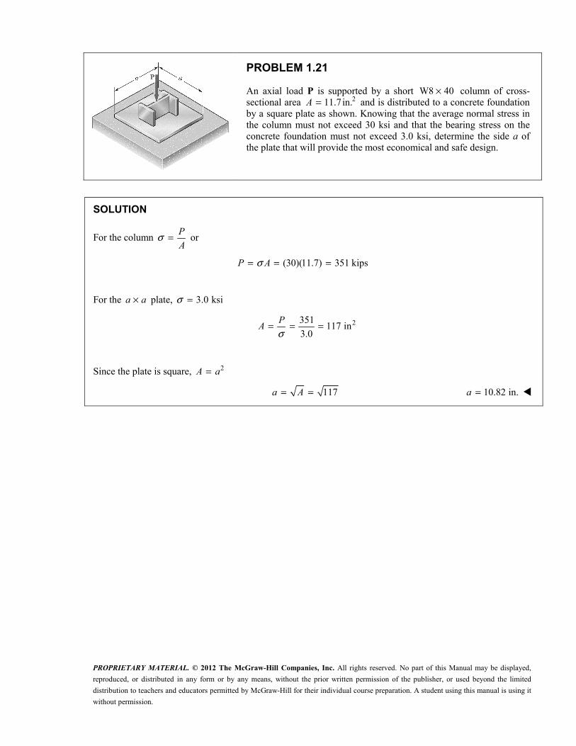
PROBLEM 1.21
An axial load P is supported by a short W8 40× column of cross-sectional area 211.7in.=A and is distributed to a concrete foundation by a square plate as shown. Knowing that the average normal stress in the column must not exceed 30 ksi and that the bearing stress on the concrete foundation must not exceed 3.0 ksi, determine the side a of the plate that will provide the most economical and safe design.
SOLUTION
For the column σ = P
A or
(30)(11.7) 351 kipsσ= = =P A
For the ×a a plate, 3.0 ksiσ =
2351117 in
3.0σ= = =P
A
Since the plate is square, 2=A a
117= =a A 10.82 in.=a

PROPRIETARY MATERIAL. © 2012 The McGraw-Hill Companies, Inc. All rights reserved. No part of this Manual may be displayed,
reproduced, or distributed in any form or by any means, without the prior written permission of the publisher, or used beyond the limited
distribution to teachers and educators permitted by McGraw-Hill for their individual course preparation. A student using this manual is using it
without permission.
PROBLEM 1.22
A 40-kN axial load is applied to a short wooden post that is supported by a concrete footing resting on undisturbed soil. Determine (a) the maximum bearing stress on the concrete footing, (b) the size of the footing for which the average bearing stress in the soil is 145 kPa.
SOLUTION
(a) Bearing stress on concrete footing.
3
3 2 3 2
36
3
40kN 40 10 N
(100)(120) 12 10 mm 12 10 m
40 103.333 10 Pa
12 10σ
−
−
= = ×
= = × = ×
×= = = ××
P
A
P
A 3.33 MPa
(b) Footing area. 3 340 10 N 145 kPa 45 10 Paσ= × = = ×P
3
23
40 100.27586 m
145 10
P PA
Aσ
σ×= = = =×
Since the area is square, 2=A b
0.27586 0.525 m= = =b A 525 mm=b

PROPRIETARY MATERIAL. © 2012 The McGraw-Hill Companies, Inc. All rights reserved. No part of this Manual may be displayed,
reproduced, or distributed in any form or by any means, without the prior written permission of the publisher, or used beyond the limited
distribution to teachers and educators permitted by McGraw-Hill for their individual course preparation. A student using this manual is using it
without permission.
PROBLEM 1.23
A 58
-in.-diameter steel rod AB is fitted to a round hole near end C of the wooden member CD. For the loading shown, determine (a) the maximum average normal stress in the wood, (b) the distance b for which the average shearing stress is 100 psi on the surfaces indicated by the dashed lines, (c) the average bearing stress on the wood.
SOLUTION
(a) Maximum normal stress in the wood
2net
net
5(1) 4 3.375 in.
8
1500444 psi
3.375σ
= − =
= = =
A
P
A 444 psiσ =
(b) Distance b for τ = 100 psi
For sheared area see dotted lines.
21500
7.50 in.2 (2)(1)(100)
τ
τ
= =
= = =
P P
A btP
bt
7.50 in.=b
(c) Average bearing stress on the wood
1500
2400 psi5
(1)8
σ = = = =
bb
P P
A dt 2400 psiσ =b

PROPRIETARY MATERIAL. © 2012 The McGraw-Hill Companies, Inc. All rights reserved. No part of this Manual may be displayed,
reproduced, or distributed in any form or by any means, without the prior written permission of the publisher, or used beyond the limited
distribution to teachers and educators permitted by McGraw-Hill for their individual course preparation. A student using this manual is using it
without permission.
PROBLEM 1.24
Knowing that θ = 40° and P = 9 kN, determine (a) the smallest allowable diameter of the pin at B if the average shearing stress in the pin is not to exceed 120 MPa, (b) the corresponding average bearing stress in member AB at B, (c) the corresponding average bearing stress in each of the support brackets at B.
SOLUTION
Geometry: Triangle ABC is an isoseles triangle with angles shown here.
Use joint A as a free body.
Law of sines applied to force triangle
sin 20 sin110 sin 50sin110
sin 20(9)sin110
24.73 kNsin 20
= =° ° °
°=°
°= =°
AB AC
AB
P F F
PF

PROPRIETARY MATERIAL. © 2012 The McGraw-Hill Companies, Inc. All rights reserved. No part of this Manual may be displayed,
reproduced, or distributed in any form or by any means, without the prior written permission of the publisher, or used beyond the limited
distribution to teachers and educators permitted by McGraw-Hill for their individual course preparation. A student using this manual is using it
without permission.
PROBLEM 1.24 (Continued)
(a) Allowable pin diameter.
2 2
4
2
2 2 πτπ
= = =AB AB AB
P
F F F
A d d where 324.73 10 N= ×ABF
3
2 6 26
2 (2)(24.73 10 )131.18 10 m
(120 10 )πτ π−×= = = ×
×ABF
d
311.45 10 m−= ×d 11.45 mm
(b) Bearing stress in AB at A.
3 6 2
36
6
(0.016)(11.45 10 ) 183.26 10 m
24.73 10134.9 10
183.26 10σ
− −
−
= = × = ×
×= = = ××
b
ABb
b
A td
F
A 134.9 MPa
(c) Bearing stress in support brackets at B.
3 6 2
1 362
6
(0.012)(11.45 10 ) 137.4 10 m
(0.5)(24.73 10 )90.0 10
137.4 10σ
− −
−
= = × = ×
×= = = ××
ABb
A td
F
A 90.0 MPa

PROPRIETARY MATERIAL. © 2012 The McGraw-Hill Companies, Inc. All rights reserved. No part of this Manual may be displayed,
reproduced, or distributed in any form or by any means, without the prior written permission of the publisher, or used beyond the limited
distribution to teachers and educators permitted by McGraw-Hill for their individual course preparation. A student using this manual is using it
without permission.
PROBLEM 1.25
Determine the largest load P which may be applied at A when θ = 60°, knowing that the average shearing stress in the 10-mm-diameter pin at B must not exceed 120 MPa and that the average bearing stress in member AB and in the bracket at B must not exceed 90 MPa.
SOLUTION
Geometry: Triangle ABC is an isoseles triangle with angles shown here.
Use joint A as a free body.
Law of sines applied to force triangle
sin 30 sin 120 sin 30
sin 300.57735
sin 120
sin 30
sin 30
= =° ° °
°= =°
°= =°
AB AC
ABAB
ACAC
P F F
FP F
FP F

PROPRIETARY MATERIAL. © 2012 The McGraw-Hill Companies, Inc. All rights reserved. No part of this Manual may be displayed,
reproduced, or distributed in any form or by any means, without the prior written permission of the publisher, or used beyond the limited
distribution to teachers and educators permitted by McGraw-Hill for their individual course preparation. A student using this manual is using it
without permission.
PROBLEM 1.25 (Continued)
If shearing stress in pin at B is critical,
2 2 6 2
6 6 3
(0.010) 78.54 10 m4 4
2 (2)(78.54 10 )(120 10 ) 18.850 10 NAB
A d
F A
π π
τ
−
−
= = = ×
= = × × = ×
If bearing stress in member AB at bracket at A is critical,
6 2
6 6 3
(0.016)(0.010) 160 10 m
(160 10 )(90 10 ) 14.40 10 Nσ
−
−
= = = ×
= = × × = ×b
AB b b
A td
F A
If bearing stress in the bracket at B is critical,
6 2
6 6 3
2 (2)(0.012)(0.010) 240 10 m
(240 10 )(90 10 ) 21.6 10 Nσ
−
−
= = = ×
= = × × = ×b
AB b b
A td
F A
Allowable FAB is the smallest, i.e., 14.40 × 10³N
Then from Statics 3allow (0.57735)(14.40 10 )= ×P
38.31 10 N= × 8.31 kN

PROPRIETARY MATERIAL. © 2012 The McGraw-Hill Companies, Inc. All rights reserved. No part of this Manual may be displayed,
reproduced, or distributed in any form or by any means, without the prior written permission of the publisher, or used beyond the limited
distribution to teachers and educators permitted by McGraw-Hill for their individual course preparation. A student using this manual is using it
without permission.
PROBLEM 1.26
Link AB, of width b = 50 mm and thickness t = 6 mm, is used to support the end of a horizontal beam. Knowing that the average normal stress in the link is − 140 MPa, and that the average shearing stress in each of the two pins is 80 MPa, determine (a) the diameter d of the pins, (b) the average bearing stress in the link.
SOLUTION
Rod AB is in compression.
=A bt where 50 mm=b and 6 mm=t
6 2
6 6
3
(0.050)(0.006) 300 10 m
( 140 10 )(300 10 )
42 10 N
σ
−
−
= = ×
= − = − − × ×
= ×
A
P A
For the pin,
2
4pA dπ= and τ =
p
P
A
3
6 26
42 10525 10 m
80 10τ−×= = = ×
×pP
A
(a) Diameter d
6
34 (4)(525 10 )2.585 10 mpA
dπ π
−−×= = = × 25.9 mm=d
(b) Bearing stress 3
63
42 10271 10 Pa
(25.85 10 )(0.006)σ −
×= = = ××b
P
dt 271 MPaσ =b

PROPRIETARY MATERIAL. © 2012 The McGraw-Hill Companies, Inc. All rights reserved. No part of this Manual may be displayed,
reproduced, or distributed in any form or by any means, without the prior written permission of the publisher, or used beyond the limited
distribution to teachers and educators permitted by McGraw-Hill for their individual course preparation. A student using this manual is using it
without permission.
PROBLEM 1.27
For the assembly and loading of Prob. 1.7, determine (a) the average shearing stress in the pin at B, (b) the average bearing stress at B in member BD, (c) the average bearing stress at B in member ABC, knowing that this member has a 10 × 50-mm uniform rectangular cross section.
PROBLEM 1.7 Each of the four vertical links has an 8 × 36-mm uniform rectangular cross section and each of the four pins has a 16-mm diameter. Determine the maximum value of the average normal stress in the links connecting (a) points B and D, (b) points C and E.
SOLUTION
Use bar ABC as a free body.
3
3
0 : (0.040) (0.025 0.040)(20 10 ) 0
32.5 10 N
Σ = − + × =
= ×C BD
BD
M F
F
(a) Shear pin at B 2
τ = BDF
A for double shear,
where 2 2 6 2(0.016) 201.06 10 m4 4
π π −= = = ×A d
3
66
32.5 1080.8 10
(2)(201.06 10 )τ −
×= = ××
80.8 MPaτ =
(b) Bearing: link BD 6 2(0.016)(0.008) 128 10 m−= = = ×A dt
1 3
626
(0.5)(32.5 10 )126.95 10
128 10σ −
×= = = ××
BDb
F
A 127.0 MPaσ =b
(c) Bearing in ABC at B 6 2(0.016)(0.010) 160 10 m−= = = ×A dt
3
66
32.5 10203 10
160 10σ −
×= = = ××
BDb
F
A 203 MPaσ =b

PROPRIETARY MATERIAL. © 2012 The McGraw-Hill Companies, Inc. All rights reserved. No part of this Manual may be displayed,
reproduced, or distributed in any form or by any means, without the prior written permission of the publisher, or used beyond the limited
distribution to teachers and educators permitted by McGraw-Hill for their individual course preparation. A student using this manual is using it
without permission.
PROBLEM 1.28
The hydraulic cylinder CF, which partially controls the position of rod DE, has been locked in the position shown. Member BD is 5
8 in. thick and is connected to the vertical rod by a 3
8 -in.-diameter bolt. Determine (a) the average shearing stress in the bolt, (b) the bearing stress at C in member BD.
SOLUTION
Use member BCD as a free body, and note that AB is a two force member.
2 28 1.8 8.2 in.= + =ABl
8 1.8
0: (4cos 20 ) (4sin 20 )8.2 8.2
(7cos 20 )(400sin 75 ) (7sin 20 )(400cos75 ) 0
3.36678 2789.35 0 828.49 lb
Σ = ° − °
− ° ° − ° ° =− = ∴ =
C AB AB
AB AB
M F F
F F
1.8
0: 400cos75 08.2
(1.8)(828.49)400cos75 78.34 lb
8.2
Σ = − + + ° =
= − ° =
x AB x
x
F F C
C
2 2
80: 400sin 75 0
8.2(8)(828.49)
400sin 75 1194.65 lb8.2
1197.2 lb
Σ = − + − ° =
= + ° =
= + =
y AB y
y
x y
F F C
C
C C C

PROPRIETARY MATERIAL. © 2012 The McGraw-Hill Companies, Inc. All rights reserved. No part of this Manual may be displayed,
reproduced, or distributed in any form or by any means, without the prior written permission of the publisher, or used beyond the limited
distribution to teachers and educators permitted by McGraw-Hill for their individual course preparation. A student using this manual is using it
without permission.
PROBLEM 1.28 (Continued)
(a) Shearing stress in the bolt: 1197.2 lb=P 2
2 230.11045 in
4 4 8
π π = = =
A d
31197.210.84 10 psi
0.11045τ = = = × =P
A 10.84 ksi
(b) Bearing stress at C in member BCD: 1197.2 lb=P 23 50.234375 in
8 8 = = =
bA dt
31197.25.11 10 psi
0.234375σ = = = × =b
b
P
A 5.11 ksi

PROPRIETARY MATERIAL. © 2012 The McGraw-Hill Companies, Inc. All rights reserved. No part of this Manual may be displayed,
reproduced, or distributed in any form or by any means, without the prior written permission of the publisher, or used beyond the limited
distribution to teachers and educators permitted by McGraw-Hill for their individual course preparation. A student using this manual is using it
without permission.
PROBLEM 1.29
The 1.4-kip load P is supported by two wooden members of uniform cross section that are joined by the simple glued scarf splice shown. Determine the normal and shearing stresses in the glued splice.
SOLUTION
20
2 2
0
1400 lb 90 60 30
(5.0)(3.0) 15 in
cos (1400)(cos30 )
15
P
A
P
A
θ
θσ
= = ° − ° = °
= =
°= = 70.0 psiσ =
0
sin 2 (1400)sin 60
2 (2)(15)
θτ °= =P
A 40.4 psiτ =
PROPRIETARY MATERIAL. © 2012 The McGraw-Hill Companies, Inc. All rights reserved. No part of this Manual may be displayed,
reproduced, or distributed in any form or by any means, without the prior written permission of the publisher, or used beyond the limited
distribution to teachers and educators permitted by McGraw-Hill for their individual course preparation. A student using this manual is using it
without permission.
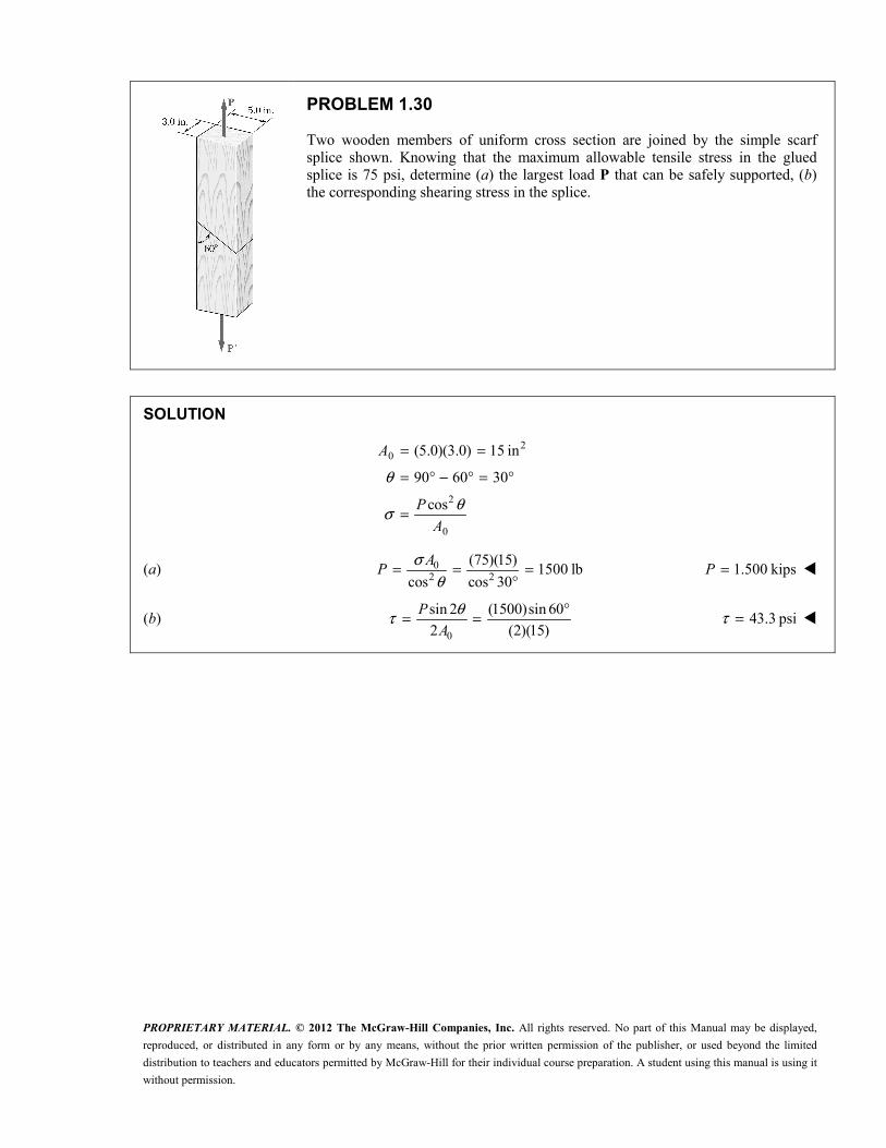
PROBLEM 1.30
Two wooden members of uniform cross section are joined by the simple scarf splice shown. Knowing that the maximum allowable tensile stress in the glued splice is 75 psi, determine (a) the largest load P that can be safely supported, (b) the corresponding shearing stress in the splice.
SOLUTION
20
2
0
(5.0)(3.0) 15 in
90 60 30
cos
θ
θσ
= =
= ° − ° = °
=
A
P
A
(a) 02 2
(75)(15)1500 lb
cos cos 30
σθ
= = =°
AP 1.500 kips=P
(b) 0
sin 2 (1500)sin 60
2 (2)(15)
θτ °= =P
A 43.3 psiτ =

PROPRIETARY MATERIAL. © 2012 The McGraw-Hill Companies, Inc. All rights reserved. No part of this Manual may be displayed,
reproduced, or distributed in any form or by any means, without the prior written permission of the publisher, or used beyond the limited
distribution to teachers and educators permitted by McGraw-Hill for their individual course preparation. A student using this manual is using it
without permission.
PROBLEM 1.31
Two wooden members of uniform rectangular cross section are joined by the simple glued scarf splice shown. Knowing that P = 11 kN, determine the normal and shearing stresses in the glued splice.
SOLUTION
3
3 2 3 20
2 3 23
30
90 45 45
11 kN 11 10 N
(150)(75) 11.25 10 mm 11.25 10 m
cos (11 10 )cos 45489 10 Pa
11.25 10
θ
θσ
−
−
= ° − ° = °
= = ×
= = × = ×
× °= = = ××
P
A
P
A 489 kPaσ =
3
33
0
sin 2 (11 10 )(sin 90 )489 10 Pa
2 (2)(11.25 10 )
P
A
θτ −× °= = = ×
× 489 kPaτ =

PROPRIETARY MATERIAL. © 2012 The McGraw-Hill Companies, Inc. All rights reserved. No part of this Manual may be displayed,
reproduced, or distributed in any form or by any means, without the prior written permission of the publisher, or used beyond the limited
distribution to teachers and educators permitted by McGraw-Hill for their individual course preparation. A student using this manual is using it
without permission.
PROBLEM 1.32
Two wooden members of uniform rectangular cross section are joined by the simple glued scarf splice shown. Knowing that the maximum allowable shearing stress in the glued splice is 620 kPa, determine (a) the largest load P that can be safely applied, (b) the corresponding tensile stress in the splice.
SOLUTION
3 2 3 20
3
0
90 45 45
(150)(75) 11.25 10 mm 11.25 10 m
620 kPa 620 10 Pa
sin 2
2
A
P
A
θ
τθτ
−
= ° − ° = °
= = × = ×
= = ×
=
(a) 3 3
02 (2)(11.25 10 )(620 10 )
sin2 sin 90
τθ
−× ×= =°
AP
313.95 10 N= × 13.95 kN=P
(b) 2 3 2
30
cos (13.95 10 )(cos 45 )
11.25 10
θσ −× °= =
×P
A
3620 10 Pa= × 620 kPaσ =

PROPRIETARY MATERIAL. © 2012 The McGraw-Hill Companies, Inc. All rights reserved. No part of this Manual may be displayed,
reproduced, or distributed in any form or by any means, without the prior written permission of the publisher, or used beyond the limited
distribution to teachers and educators permitted by McGraw-Hill for their individual course preparation. A student using this manual is using it
without permission.
PROBLEM 1.33
A steel pipe of 12-in. outer diameter is fabricated from 14
-in.-thick plate by welding along a helix that forms an angle of 25° with a plane perpendicular to the axis of the pipe. Knowing that the maximum allowable normal and shearing stresses in the directions respectively normal and tangential to the weld are 12σ = ksi and 7.2τ = ksi, determine the magnitude P of the largest axial force that can be applied to the pipe.
SOLUTION
2 2 2 2 2
0
112 in. 6 in.
26 0.25 5.75 in.
( ) (6 5.75 ) 9.228 in
25
π πθ
= = =
= − = − =
= − = − == °
o o o
i o
o i
d r d
r r t
A r r
Based on 2
0
12 ksi: cosσ σ θ= = P
A
3
302 2
(9.228)(12 10 )134.8 10 lb
cos cos 25
σθ
×= = = ×°
AP
Based on 0
7.2 ksi: sin 22
τ τ θ= = P
A
3
302 (2)(9.288)(7.2 10 )174.5 10 lb
sin 2 sin 50
τθ
×= = = ×°
AP
The smaller calculated value of P is the allowable value.
3134.8 10 lb= ×P 134.8 kips=P

PROPRIETARY MATERIAL. © 2012 The McGraw-Hill Companies, Inc. All rights reserved. No part of this Manual may be displayed,
reproduced, or distributed in any form or by any means, without the prior written permission of the publisher, or used beyond the limited
distribution to teachers and educators permitted by McGraw-Hill for their individual course preparation. A student using this manual is using it
without permission.
PROBLEM 1.34
A steel pipe of 12-in. outer diameter is fabricated from 14
-in.-thick plate by welding along a helix that forms an angle of 25° with a plane perpendicular to the axis of the pipe. Knowing that a 66 kip axial force P is applied to the pipe, determine the normal and shearing stresses in directions respectively normal and tangential to the weld.
SOLUTION
2 2 2 2 2
0
112 in. 6 in.
26 0.25 5.75 in.
( ) (6 5.75 ) 9.228 in
25
π πθ
= = =
= − = − =
= − = − == °
o o o
i o
o i
d r d
r r t
A r r
Normal stress: 2 3 2
0
cos (66 10 )cos 255875 psi
9.228
θσ × °= = =P
A 5.87 ksiσ =
Shearing stress: 3
0
sin 2 (66 10 )sin 502739 psi
2 (2)(9.228)
θτ × °= = =P
A 2.74 ksiτ =

PROPRIETARY MATERIAL. © 2012 The McGraw-Hill Companies, Inc. All rights reserved. No part of this Manual may be displayed,
reproduced, or distributed in any form or by any means, without the prior written permission of the publisher, or used beyond the limited
distribution to teachers and educators permitted by McGraw-Hill for their individual course preparation. A student using this manual is using it
without permission.
PROBLEM 1.35
A 1060-kN load P is applied to the granite block shown. Determine the resulting maximum value of (a) the normal stress, (b) the shearing stress. Specify the orientation of the plane on which each of these maximum values occurs.
SOLUTION
3 2 3 20
3
32 2 6 2
30
(140 mm)(140 mm) 19.6 10 mm 19.6 10 m
1060 10 N
1060 10cos cos 54.082 10 cos
19.6 10σ θ θ θ
−
−
= = × = ×
= ×
×= = = ××
A
P
P
A
(a) Maximum tensile stress = 0 at θ = 90°.
Maximum compressive stress = 54.1 × 10⁶ at θ = 0°. max| | 54.1 MPaσ =
(b) Maximum shearing stress:
3
6max 3
0
1060 1027.0 10 Pa at 45 .
2 (2)(19.6 10 )τ θ−
×= = = × = °×
P
A max 27.0 MPaτ =

PROPRIETARY MATERIAL. © 2012 The McGraw-Hill Companies, Inc. All rights reserved. No part of this Manual may be displayed,
reproduced, or distributed in any form or by any means, without the prior written permission of the publisher, or used beyond the limited
distribution to teachers and educators permitted by McGraw-Hill for their individual course preparation. A student using this manual is using it
without permission.
PROBLEM 1.36
A centric load P is applied to the granite block shown. Knowing that the resulting maximum value of the shearing stress in the block is 18 MPa, determine (a) the magnitude of P, (b) the orientation of the surface on which the maximum shearing stress occurs, (c) the normal stress exerted on that surface, (d) the maximum value of the normal stress in the block.
SOLUTION
3 2 3 20
6max
max
(140 mm)(140 mm) 19.6 10 mm 19.6 10 m
18 MPa 18 10 Pa
45 for plane of
τθ τ
−= = × = ×
= = ×= °
A
(a) Magnitude of P. max 0 max0
| |so 2
2τ τ= =P
P AA
3 6 3(2)(19.6 10 )(18 10 ) 705.6 10 N−= × × = ×P 706 kN=P
(b) Orientation. sin 2θ is maximum when 2 90θ = ° 45θ = °
(c) Normal stress at θ = 45°.
2 3 2
63
0
cos (705.8 10 )cos 4518.00 10 Pa
19.6 10
θσ −× °= = = ×
×P
A 18.00 MPaσ =
(d) Maximum normal stress: max0
σ = P
A
3
6max 3
705.8 1036.0 10 Pa
19.6 10σ −
×= = ××
max 36.0 MPaσ = (compression)

PROPRIETARY MATERIAL. © 2012 The McGraw-Hill Companies, Inc. All rights reserved. No part of this Manual may be displayed,
reproduced, or distributed in any form or by any means, without the prior written permission of the publisher, or used beyond the limited
distribution to teachers and educators permitted by McGraw-Hill for their individual course preparation. A student using this manual is using it
without permission.
PROBLEM 1.37
Link BC is 6 mm thick, has a width w = 25 mm, and is made of a steel with a 480-MPa ultimate strength in tension. What was the safety factor used if the structure shown was designed to support a 16-kN load P?
SOLUTION
Use bar ACD as a free body and note that member BC is a two-force member.
3
3
0:
(480) (600) 0
600 (600)(16 10 )20 10 N
480 480
Σ =− =
×= = = ×
A
BC
BC
M
F P
F P
Ultimate load for member BC: U UF Aσ=
6 3(480 10 )(0.006)(0.025) 72 10 N= × = ×UF
Factor of safety: 3
3
72 10F.S.
20 10
×= =×
U
BC
F
F F.S. 3.60=
PROPRIETARY MATERIAL. © 2012 The McGraw-Hill Companies, Inc. All rights reserved. No part of this Manual may be displayed,
reproduced, or distributed in any form or by any means, without the prior written permission of the publisher, or used beyond the limited
distribution to teachers and educators permitted by McGraw-Hill for their individual course preparation. A student using this manual is using it
without permission.
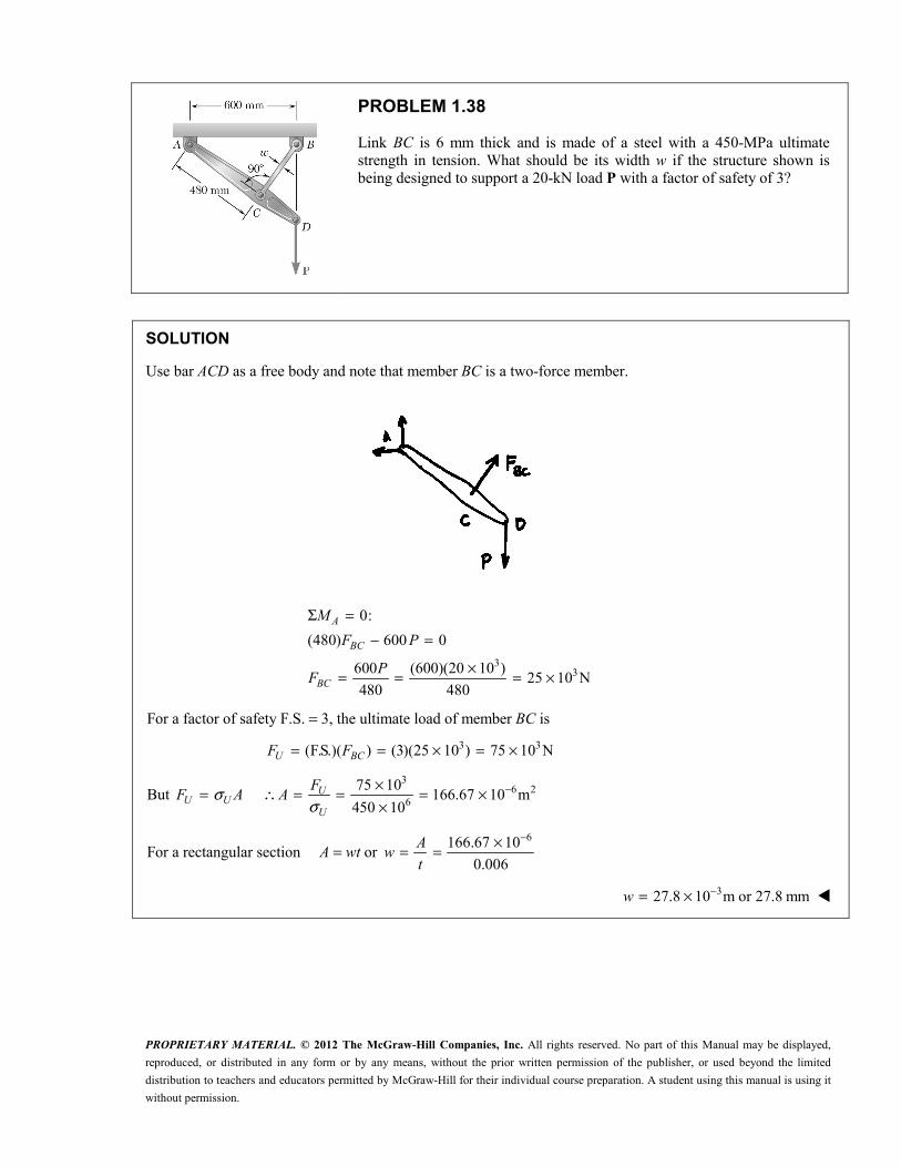
PROBLEM 1.38
Link BC is 6 mm thick and is made of a steel with a 450-MPa ultimate strength in tension. What should be its width w if the structure shown is being designed to support a 20-kN load P with a factor of safety of 3?
SOLUTION
Use bar ACD as a free body and note that member BC is a two-force member.
3
3
0:
(480) 600 0
600 (600)(20 10 )25 10 N
480 480
Σ =− =
×= = = ×
A
BC
BC
M
F P
PF
For a factor of safety F.S. = 3, the ultimate load of member BC is
3 3(F.S.)( ) (3)(25 10 ) 75 10 N= = × = ×U BCF F
But σ=U UF A 3
6 26
75 10166.67 10 m
450 10σ−×∴ = = = ×
×U
U
FA
For a rectangular section A = wt or 6166.67 10
0.006
−×= =Aw
t
327.8 10 m or 27.8 mm−= ×w

PROPRIETARY MATERIAL. © 2012 The McGraw-Hill Companies, Inc. All rights reserved. No part of this Manual may be displayed,
reproduced, or distributed in any form or by any means, without the prior written permission of the publisher, or used beyond the limited
distribution to teachers and educators permitted by McGraw-Hill for their individual course preparation. A student using this manual is using it
without permission.
PROBLEM 1.39
A 34
-in.-diameter rod made of the same material as rods AC and AD in the truss shown was tested to failure and an ultimate load of 29 kips was recorded. Using a factor of safety of 3.0, determine the required diameter (a) of rod AC, (b) of rod AD.
SOLUTION
Forces in AC and AD.
Joint C:
10: 10 kips 0
5
22.36 kips
Σ = − =
=
y AC
AC
F F
F T
Joint D:
10: 10 kips 0
17
41.23 kips
Σ = − =
=
y AD
AD
F F
F T
Ultimate stress. From test on 34
-in. rod: 231
4 4
29 kips65.64 ksi
( )σ
π= = =U
UP
A
Allowable stress: 65.64 ksi
21.88 ksi. . 3.0
σσ = = =Uall F S
(a) Diameter of rod AC. 2all 21
all4
4 4(22.36)1.301
(21.88)AC ACF F
dd
σπσ ππ
= = = = 1.141 in.=d
(b) Diameter of rod AD. 2
all
4 4(41.23)2.399
(21.88)πσ π= = =ADF
d 1.549 in.=d

PROPRIETARY MATERIAL. © 2012 The McGraw-Hill Companies, Inc. All rights reserved. No part of this Manual may be displayed,
reproduced, or distributed in any form or by any means, without the prior written permission of the publisher, or used beyond the limited
distribution to teachers and educators permitted by McGraw-Hill for their individual course preparation. A student using this manual is using it
without permission.
PROBLEM 1.40
In the truss shown, members AC and AD consist of rods made of the same metal alloy. Knowing that AC is of 1-in. diameter and that the ultimate load for that rod is 75 kips, determine (a) the factor of safety for AC, (b) the required diameter of AD if it is desired that both rods have the same factor of safety.
SOLUTION
Forces in AC and AD.
Joint C:
10: 10 kips 0
5
22.36 kips
y AC
AC
F F
F T
Σ = − =
=
Joint D:
10: 10 kips 0
17
41.23 kips
y AD
AD
F F
F T
Σ = − =
=
(a) Factor of safety for AC. F.S. = U
AC
P
F
75 kipsF.S.
22.36 kips= F.S. 3.35=
(b) For the same factor of safety in AC and AD, .σ σ=AD AC
2 241.23
(1) 1.4482 in22.36 4
π
=
= = =
AD AC
AD AC
ADAD AC
AC
F F
A A
FA A
F
Required diameter: 4 (4)(1.4482)
π π= =AD
ADA
d 1.358 in.=ADd

PROPRIETARY MATERIAL. © 2012 The McGraw-Hill Companies, Inc. All rights reserved. No part of this Manual may be displayed,
reproduced, or distributed in any form or by any means, without the prior written permission of the publisher, or used beyond the limited
distribution to teachers and educators permitted by McGraw-Hill for their individual course preparation. A student using this manual is using it
without permission.
PROBLEM 1.41
Link AB is to be made of a steel for which the ultimate normal stress is 450 MPa. Determine the cross-sectional area for AB for which the factor of safety will be 3.50. Assume that the link will be adequately reinforced around the pins at A and B.
SOLUTION
(1.2)(8) 9.6 kN= =P
0 : (0.8)( sin 35 )
(0.2)(9.6) (0.4)(20) 0D ABM FΣ = − °
+ + =
3
ult
3
6ult
6 2
21.619 kN 21.619 10 N
. .
( . .) (3.50)(21.619 10 )
450 10
168.1 10 m
AB
ABAB
AB
ABAB
F
F
A F S
F S FA
σσ
σ−
= = ×
= =
×= =×
= × 2168.1 mm=ABA

PROPRIETARY MATERIAL. © 2012 The McGraw-Hill Companies, Inc. All rights reserved. No part of this Manual may be displayed,
reproduced, or distributed in any form or by any means, without the prior written permission of the publisher, or used beyond the limited
distribution to teachers and educators permitted by McGraw-Hill for their individual course preparation. A student using this manual is using it
without permission.
PROBLEM 1.42
A steel loop ABCD of length 1.2 m and of 10-mm diameter is placed as shown around a 24-mm-diameter aluminum rod AC. Cables BE and DF, each of 12-mm diameter, are used to apply the load Q. Knowing that the ultimate strength of the steel used for the loop and the cables is 480 MPa and that the ultimate strength of the aluminum used for the rod is 260 MPa, determine the largest load Q that can be applied if an overall factor of safety of 3 is desired.
SOLUTION
Using joint B as a free body and considering symmetry,
3 6
2 05 5
⋅ − = =AB ABF Q Q F
Using joint A as a free body and considering symmetry,
42 0
58 5 3
05 6 4
⋅ − =
⋅ − = ∴ =
AB AC
AC AC
F F
Q F Q F
Based on strength of cable BF:
2 6 2 3(480 10 ) (0.012) 54.29 10 N4 4
π πσ σ= = = × = ×U U UQ A d
Based on strength of steel loop:
2,
6 2 3
6 6 6
5 5 5 46
(480 10 ) (0.010) 45.24 10 N5 4
πσ σ
π
= = =
= × = ×
U AB U U UQ F A d
Based on strength of rod AC:
2 6 2 3,
3 3 3 3(260 10 ) (0.024) 88.22 10 N
4 4 4 4 4 4
π πσ σ= = = = × = ×U AC U U UQ F A d
Actual ultimate load QU is the smallest, 345.24 10 NUQ∴ = ×
Allowable load: 3
345.24 1015.08 10 N
. . 3
×= = = ×UQQ
F S 15.08 kNQ =

PROPRIETARY MATERIAL. © 2012 The McGraw-Hill Companies, Inc. All rights reserved. No part of this Manual may be displayed,
reproduced, or distributed in any form or by any means, without the prior written permission of the publisher, or used beyond the limited
distribution to teachers and educators permitted by McGraw-Hill for their individual course preparation. A student using this manual is using it
without permission.
PROBLEM 1.43
Two wooden members shown, which support a 3.6 kip load, are joined by plywood splices fully glued on the surfaces in contact. The ultimate shearing stress in the glue is 360 psi and the clearance between the members is 1
4 in. Determine the required length L of each splice if a
factor of safety of 2.75 is to be achieved.
SOLUTION
There are 4 separate areas of glue. Let l be the length of each area and 5 in.w = its width. Then the area
is .A lw=
Each glue area transmits one half of the total load.
1
(3.6 kips) 1.8 kips2
= =
F
Required ultimate load for each glue area:
( . .) (2.75)(1.8) 4.95 kips= = =UF F S F
Required length of each glue area:
34.95 102.75 in.
(360)(5)
τ τ
τ
= =
×= = =
U U U
U
U
F A lw
Fl
w
Total length of splice: 1
in.4
L l= + + l
2.75 0.25 2.75L = + + 5.75 in.L =

PROPRIETARY MATERIAL. © 2012 The McGraw-Hill Companies, Inc. All rights reserved. No part of this Manual may be displayed,
reproduced, or distributed in any form or by any means, without the prior written permission of the publisher, or used beyond the limited
distribution to teachers and educators permitted by McGraw-Hill for their individual course preparation. A student using this manual is using it
without permission.
PROBLEM 1.44
Two plates, each 18
in. thick, are used to splice a plastic strip as shown. Knowing that the ultimate shearing stress of the bonding between the surface is 130 psi, determine the factor of safety with respect to shear when 325 lb.P =
SOLUTION
Bond area: (See figure)
21(2.25)(0.75) (2.25)(0.625) 2.25 in
2A = + =
2 (2)(2.25)(130) 585 lb.U UP Aτ= = =
585
. . 1.800325
UPF S
P= = =
PROPRIETARY MATERIAL. © 2012 The McGraw-Hill Companies, Inc. All rights reserved. No part of this Manual may be displayed,
reproduced, or distributed in any form or by any means, without the prior written permission of the publisher, or used beyond the limited
distribution to teachers and educators permitted by McGraw-Hill for their individual course preparation. A student using this manual is using it
without permission.
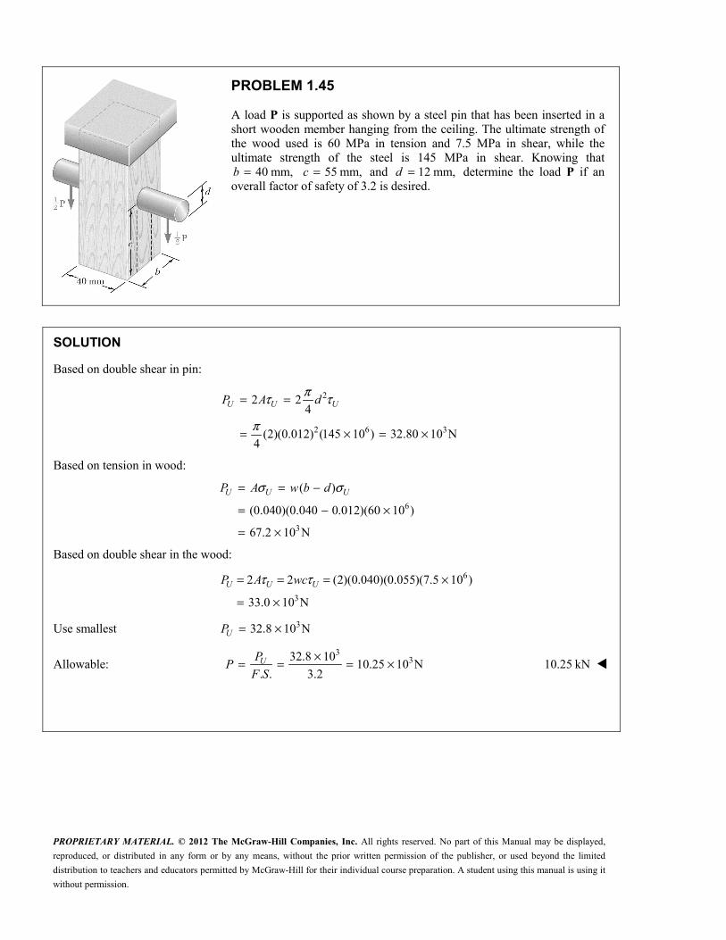
PROBLEM 1.45
A load P is supported as shown by a steel pin that has been inserted in a short wooden member hanging from the ceiling. The ultimate strength of the wood used is 60 MPa in tension and 7.5 MPa in shear, while the ultimate strength of the steel is 145 MPa in shear. Knowing that
40 mm,b = 55 mm,c = and 12 mm,d = determine the load P if an overall factor of safety of 3.2 is desired.
SOLUTION
Based on double shear in pin:
2
2 6 3
2 24
(2)(0.012) (145 10 ) 32.80 10 N4
U U UP A dπτ τ
π
= =
= × = ×
Based on tension in wood:
6
3
( )
(0.040)(0.040 0.012)(60 10 )
67.2 10 N
σ σ= = −
= − ×
= ×
U U UP A w b d
Based on double shear in the wood:
6
3
2 2 (2)(0.040)(0.055)(7.5 10 )
33.0 10 N
τ τ= = = ×
= ×U U UP A wc
Use smallest 332.8 10 NUP = ×
Allowable: 3
332.8 1010.25 10 N
. . 3.2UP
PF S
×= = = × 10.25 kN

PROPRIETARY MATERIAL. © 2012 The McGraw-Hill Companies, Inc. All rights reserved. No part of this Manual may be displayed,
reproduced, or distributed in any form or by any means, without the prior written permission of the publisher, or used beyond the limited
distribution to teachers and educators permitted by McGraw-Hill for their individual course preparation. A student using this manual is using it
without permission.
PROBLEM 1.46
For the support of Prob. 1.45, knowing that the diameter of the pin is 16 mm=d and that the magnitude of the load is 20 kN,=P determine
(a) the factor of safety for the pin, (b) the required values of b and c if the factor of safety for the wooden members is the same as that found in part a for the pin.
PROBLEM 1.45 A load P is supported as shown by a steel pin that has been inserted in a short wooden member hanging from the ceiling. The ultimate strength of the wood used is 60 MPa in tension and 7.5 MPa in shear, while the ultimate strength of the steel is 145 MPa in shear. Knowing that 40 mm,=b 55 mm,c = and 12 mm,d = determine the load P if an overall factor of safety of 3.2 is desired.
SOLUTION
320 kN 20 10 NP = = ×
(a) Pin: 2 2 6 2(0.016) 2.01.06 10 m4 4
A dπ π −= = = ×
Double shear: 2 2
UU
P P
A Aτ τ= =
6 6 32 (2)(201.16 10 )(145 10 ) 58.336 10 Nτ −= = × × = ×U UP A
3
3
58.336 10. .
20 10
×= =×
UPF S
P . . 2.92=F S
(b) Tension in wood: 358.336 10 N for same F.S.UP = ×
where 40 mm 0.040 m( )
U UU
P Pw
A w b dσ = = = =
−
3
36
58.336 100.016 40.3 10 m
(0.040)(60 10 )U
U
Pb d
wσ−×= + = + = ×
× 40.3 mmb =
Shear in wood: 358.336 10 N for same F.S.UP = ×
Double shear; each area is A wc= 2 2
τ = =U UU
P P
A wc
3
36
58.336 1097.2 10 m
2 (2)(0.040)(7.5 10 )τ−×= = = ×
×U
U
Pc
w 97.2 mmc =

PROPRIETARY MATERIAL. © 2012 The McGraw-Hill Companies, Inc. All rights reserved. No part of this Manual may be displayed,
reproduced, or distributed in any form or by any means, without the prior written permission of the publisher, or used beyond the limited
distribution to teachers and educators permitted by McGraw-Hill for their individual course preparation. A student using this manual is using it
without permission.
PROBLEM 1.47
Three steel bolts are to be used to attach the steel plate shown to a wooden beam. Knowing that the plate will support a 110-kN load, that the ultimate shearing stress for the steel used is 360 MPa, and that a factor of safety of 3.35 is desired, determine the required diameter of the bolts.
SOLUTION
For each bolt, 110
36.667 kN3
= =P
Required: ( . .) (3.35)(36.667) 122.83 kN= = =UP F S P
2 24
33
6
4
4 (4)(122.83 10 )20.8 10 m
(360 10 )
πτπ
πτ π−
= = =
×= = = ××
U U UU
U
U
P P P
A d d
Pd 20.8 mm=d

PROPRIETARY MATERIAL. © 2012 The McGraw-Hill Companies, Inc. All rights reserved. No part of this Manual may be displayed,
reproduced, or distributed in any form or by any means, without the prior written permission of the publisher, or used beyond the limited
distribution to teachers and educators permitted by McGraw-Hill for their individual course preparation. A student using this manual is using it
without permission.
PROBLEM 1.48
Three 18-mm-diameter steel bolts are to be used to attach the steel plate shown to a wooden beam. Knowing that the plate will support a 110-kN load and that the ultimate shearing stress for the steel used is 360 MPa, determine the factor of safety for this design.
SOLUTION
For each bolt, 2 2 2 6 2(18) 254.47 mm 254.47 10 m4 4
π π −= = = = ×A d
6 6
3
(254.47 10 )(360 10 )
91.609 10 N
τ −= = × ×
= ×U UP A
For the three bolts, 3 3(3)(91.609 10 ) 274.83 10 N= × = ×UP
Factor of safety:
3
3
274.83 10. .
110 10UP
F SP
×= =×
. . 2.50F S =

PROPRIETARY MATERIAL. © 2012 The McGraw-Hill Companies, Inc. All rights reserved. No part of this Manual may be displayed,
reproduced, or distributed in any form or by any means, without the prior written permission of the publisher, or used beyond the limited
distribution to teachers and educators permitted by McGraw-Hill for their individual course preparation. A student using this manual is using it
without permission.
PROBLEM 1.49
A steel plate 516
in. thick is embedded in a horizontal concrete slab and is used to anchor a high-strength vertical cable as shown. The diameter of the hole in the plate is 3
4in., the ultimate strength of the steel used is 36 ksi,
and the ultimate bonding stress between plate and concrete is 300 psi. Knowing that a factor of safety of 3.60 is desired when P = 2.5 kips, determine (a) the required width a of the plate, (b) the minimum depth b to which a plate of that width should be embedded in the concrete slab. (Neglect the normal stresses between the concrete and the lower end of the plate.)
SOLUTION
Based on tension in plate:
( )
( ). .
σσ
= −=
−= =
U U
U U
A a d t
P A
P a d tF S
P P
Solving for a,
( )516
( . .) 3 (3.60)(2.5)
4 (36)U
F S Pa d
tσ= + = +
(a) 1.550 in.=a
Based on shear between plate and concrete slab,
perimeter depth 2( ) 0.300 ksiUA a t b τ= × = + =
2 ( ) . . UU U U
PP A a t b F S
Pτ τ= = + =
Solving for b, ( )516
( . .) (3.6)(2.5)
2( ) (2) 1.550 (0.300)U
F S Pb
a t τ= =
+ +
(b) 8.05 in.=b
PROPRIETARY MATERIAL. © 2012 The McGraw-Hill Companies, Inc. All rights reserved. No part of this Manual may be displayed,
reproduced, or distributed in any form or by any means, without the prior written permission of the publisher, or used beyond the limited
distribution to teachers and educators permitted by McGraw-Hill for their individual course preparation. A student using this manual is using it
without permission.
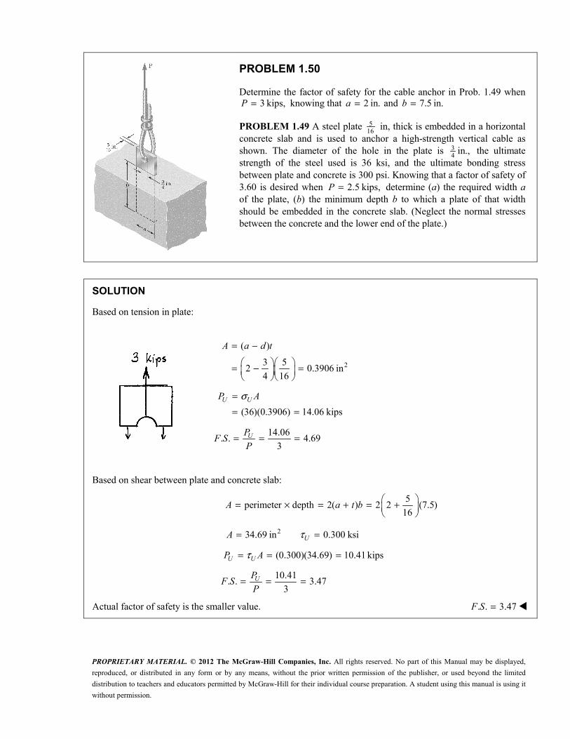
PROBLEM 1.50
Determine the factor of safety for the cable anchor in Prob. 1.49 when 3 kips,P = knowing that 2 in.a = and 7.5 in.b =
PROBLEM 1.49 A steel plate 516
in, thick is embedded in a horizontal concrete slab and is used to anchor a high-strength vertical cable as shown. The diameter of the hole in the plate is 3
4in., the ultimate
strength of the steel used is 36 ksi, and the ultimate bonding stress between plate and concrete is 300 psi. Knowing that a factor of safety of 3.60 is desired when 2.5 kips,P = determine (a) the required width a of the plate, (b) the minimum depth b to which a plate of that width should be embedded in the concrete slab. (Neglect the normal stresses between the concrete and the lower end of the plate.)
SOLUTION
Based on tension in plate:
2
( )
3 52 0.3906 in
4 16
A a d t= −
= − =
(36)(0.3906) 14.06 kipsU UP Aσ=
= =
14.06. . 4.69
3= = =UP
F SP
Based on shear between plate and concrete slab:
5
perimeter depth 2( ) 2 2 (7.5)16
= × = + = +
A a t b
234.69 in 0.300 ksiUA τ= =
(0.300)(34.69) 10.41 kipsU UP Aτ= = =
10.41
. . 3.473
UPF S
P= = =
Actual factor of safety is the smaller value. . . 3.47F S =

PROPRIETARY MATERIAL. © 2012 The McGraw-Hill Companies, Inc. All rights reserved. No part of this Manual may be displayed,
reproduced, or distributed in any form or by any means, without the prior written permission of the publisher, or used beyond the limited
distribution to teachers and educators permitted by McGraw-Hill for their individual course preparation. A student using this manual is using it
without permission.
PROBLEM 1.51
In the steel structure shown, a 6-mm-diameter pin is used at C and 10-mm-diameter pins are used at B and D. The ultimate shearing stress is 150 MPa at all connections, and the ultimate normal stress is 400 MPa in link BD. Knowing that a factor of safety of 3.0 is desired, determine the largest load P that can be applied at A. Note that link BD is not reinforced around the pin holes.
SOLUTION
Use free body ABC.
0 : 0.280 0.120 0C BDM P FΣ = − =
3
7 BDP F= (1)
0 : 0.160 0.120 0BM P CΣ = − =
3
4P C= (2)
Tension on net section of link BD.
6
3 3 3net net
400 10(6 10 )(18 10)(10 ) 6.40 10 N
. . 3
σσ − − ×= = = × − = ×
UBDF A A
F S
Shear in pins at B and D.
6
2 3 2 3pin
150 10(10 10 ) 3.9270 10 N
. . 4 3 4
τ π πτ − × = = = × = × U
BDF A dF S
Smaller value of FBD is 33.9270 10 N.×
From (1) 3 33(3.9270 10 ) 1.683 10 N
7 = × = ×
P
Shear in pin at C. 6
2 3 2 3pin
150 102 2 (2) (6 10 ) 2.8274 10 N
. . 4 3 4
τ π πτ − × = = = × = × UC A d
F S
From (2) 3 33(2.8274 10 ) 2.12 10 N
4 = × = ×
P
Smaller value of P is allowable value. 31.683 10 N= ×P 1.683 kN=P

PROPRIETARY MATERIAL. © 2012 The McGraw-Hill Companies, Inc. All rights reserved. No part of this Manual may be displayed,
reproduced, or distributed in any form or by any means, without the prior written permission of the publisher, or used beyond the limited
distribution to teachers and educators permitted by McGraw-Hill for their individual course preparation. A student using this manual is using it
without permission.
PROBLEM 1.52
Solve Prob. 1.51, assuming that the structure has been redesigned to use 12-mm-diameter pins at B and D and no other change has been made.
PROBLEM 1.51 In the steel structure shown, a 6-mm-diameter pin is used at C and 10-mm-diameter pins are used at B and D. The ultimate shearing stress is 150 MPa at all connections, and the ultimate normal stress is 400 MPa in link BD. Knowing that a factor of safety of 3.0 is desired, determine the largest load P that can be applied at A. Note that link BD is not reinforced around the pin holes.
SOLUTION
Use free body ABC.
0 : 0.280 0.120 0C BDM P FΣ = − =
3
7 BDP F= (1)
0 : 0.160 0.120 0BM P CΣ = − =
3
4P C= (2)
Tension on net section of link BD.
6
3 3 3net net
400 10(6 10 )(18 12)(10 ) 4.80 10 N
. . 3U
BDF A AF S
σσ − − ×= = = × − = ×
Shear in pins at B and D.
6
2 3 2 3pin
150 10(12 10 ) 5.6549 10 N
. . 4 3 4U
BDF A dF S
τ π πτ − × = = = × = ×
Smaller value of FBD is 34.80 10 N.×
From (1), 3 33(4.80 10 ) 2.06 10 N
7 = × = ×
P
Shear in pin at C. 6
2 3 2 3pin
150 102 2 (2) (6 10 ) 2.8274 10 N
. . 4 3 4UC A d
F S
τ π πτ − × = = = × = ×
From (2), 3 33(2.8274 10 ) 2.12 10 N
4 = × = ×
P
Smaller value of P is the allowable value. 32.06 10 N= ×P 2.06 kN=P
PROPRIETARY MATERIAL. © 2012 The McGraw-Hill Companies, Inc. All rights reserved. No part of this Manual may be displayed,
reproduced, or distributed in any form or by any means, without the prior written permission of the publisher, or used beyond the limited
distribution to teachers and educators permitted by McGraw-Hill for their individual course preparation. A student using this manual is using it
without permission.
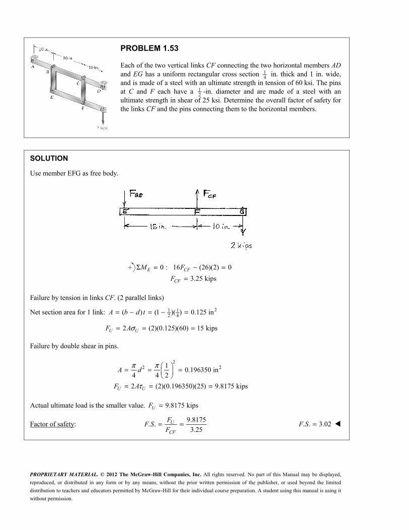
PROBLEM 1.53
Each of the two vertical links CF connecting the two horizontal members AD and EG has a uniform rectangular cross section 1
4 in. thick and 1 in. wide,
and is made of a steel with an ultimate strength in tension of 60 ksi. The pins at C and F each have a 1
2-in. diameter and are made of a steel with an
ultimate strength in shear of 25 ksi. Determine the overall factor of safety for the links CF and the pins connecting them to the horizontal members.
SOLUTION
Use member EFG as free body.
0 : 16 (26)(2) 0
3.25 kips
Σ = − ==
E CF
CF
M F
F
Failure by tension in links CF. (2 parallel links)
Net section area for 1 link: 21 12 4
( ) (1 )( ) 0.125 in= − = − =A b d t
2 (2)(0.125)(60) 15 kipsσ= = =U UF A Failure by double shear in pins.
22 21
0.196350 in4 4 2
2 (2)(0.196350)(25) 9.8175 kips
π π
τ
= = =
= = =U U
A d
F A
Actual ultimate load is the smaller value. 9.8175 kips=UF
Factor of safety: 9.8175
. .3.25
= =U
CF
FF S
F . . 3.02=F S

PROPRIETARY MATERIAL. © 2012 The McGraw-Hill Companies, Inc. All rights reserved. No part of this Manual may be displayed,
reproduced, or distributed in any form or by any means, without the prior written permission of the publisher, or used beyond the limited
distribution to teachers and educators permitted by McGraw-Hill for their individual course preparation. A student using this manual is using it
without permission.
PROBLEM 1.54
Solve Prob. 1.53, assuming that the pins at C and F have been replaced by pins with a 3
4-in diameter.
PROBLEM 1.53 Each of the two vertical links CF connecting the two horizontal members AD and EG has a uniform rectangular cross section 1
4 in.
thick and 1 in. wide, and is made of a steel with an ultimate strength in tension of 60 ksi. The pins at C and F each have a 1
2-in. diameter and are made of a
steel with an ultimate strength in shear of 25 ksi. Determine the overall factor of safety for the links CF and the pins connecting them to the horizontal members.
SOLUTION
Use member EFG as free body.
0 : 16 (26)(2) 0
3.25 kipsE CF
CF
M F
F
Σ = − ==
Failure by tension in links CF. (2 parallel links)
Net section area for 1 link: 23 14 4
( ) (1 )( ) 0.0625 inA b d t= − = − =
2 (2)(0.0625)(60) 7.5 kipsσ= = =U UF A
Failure by double shear in pins.
22 23
0.44179 in4 4 4
2 (2)(0.44179)(25) 22.09 kipsU U
A d
F A
π π
τ
= = =
= = =
Actual ultimate load is the smaller value. 7.5 kips=UF
Factor of safety: 7.5
. .3.25
= =U
CF
FF S
F . . 2.31F S =

PROPRIETARY MATERIAL. © 2012 The McGraw-Hill Companies, Inc. All rights reserved. No part of this Manual may be displayed,
reproduced, or distributed in any form or by any means, without the prior written permission of the publisher, or used beyond the limited
distribution to teachers and educators permitted by McGraw-Hill for their individual course preparation. A student using this manual is using it
without permission.
PROBLEM 1.55
In the structure shown, an 8-mm-diameter pin is used at A, and 12-mm-diameter pins are used at B and D. Knowing that the ultimate shearing stress is 100 MPa at all connections and that the ultimate normal stress is 250 MPa in each of the two links joining B and D, determine the allowable load P if an overall factor of safety of 3.0 is desired.
SOLUTION
Statics: Use ABC as free body.
10
0 : 0.20 0.18 09B A AM F P P FΣ = − = =
10
0 : 0.20 0.38 019A BD BDM F P P FΣ = − = =
Based on double shear in pin A: 2 2 6 2(0.008) 50.266 10 m4 4
π π −= = = ×A d
6 63
3
2 (2)(100 10 )(50.266 10 )3.351 10 N
. . 3.010
3.72 10 N9
τ −× ×= = = ×
= = ×
UA
A
AF
F S
P F
Based on double shear in pins at B and D: 2 2 6 2(0.012) 113.10 10 m4 4
π π −= = = ×A d
6 63
3
2 (2)(100 10 )(113.10 10 )7.54 10 N
. . 3.010
3.97 10 N19
τ −× ×= = = ×
= = ×
UBD
BD
AF
F S
P F
Based on compression in links BD: For one link, 6 2(0.020)(0.008) 160 10 m−= = ×A
6 6
3
3
2 (2)(250 10 )(160 10 )26.7 10 N
. . 3.010
14.04 10 N19
σ −× ×= = = ×
= = ×
UBD
BD
AF
F S
P F
Allowable value of P is smallest, ∴ 33.72 10 N= ×P 3.72 kN=P

PROPRIETARY MATERIAL. © 2012 The McGraw-Hill Companies, Inc. All rights reserved. No part of this Manual may be displayed,
reproduced, or distributed in any form or by any means, without the prior written permission of the publisher, or used beyond the limited
distribution to teachers and educators permitted by McGraw-Hill for their individual course preparation. A student using this manual is using it
without permission.
PROBLEM 1.56
In an alternative design for the structure of Prob. 1.55, a pin of 10-mm-diameter is to be used at A. Assuming that all other specifications remain unchanged, determine the allowable load P if an overall factor of safety of 3.0 is desired.
PROBLEM 1.55 In the structure shown, an 8-mm-diameter pin is used at A, and 12-mm-diameter pins are used at B and D. Knowing that the ultimate shearing stress is 100 MPa at all connections and that the ultimate normal stress is 250 MPa in each of the two links joining B and D, determine the allowable load P if an overall factor of safety of 3.0 is desired.
SOLUTION
Statics: Use ABC as free body.
100: 0.20 0.18 0
9B A AM F P P FΣ = − = =
100: 0.20 0.38 0
19A BD BDM F P P FΣ = − = =
Based on double shear in pin A: 2 2 6 2(0.010) 78.54 10 m4 4
π π −= = = ×A d
6 63
3
2 (2)(100 10 )(78.54 10 )5.236 10 N
. . 3.010
5.82 10 N9
τ −× ×= = = ×
= = ×
UA
A
AF
F S
P F
Based on double shear in pins at B and D: 2 2 6 2(0.012) 113.10 10 m4 4
π π −= = = ×A d
6 63
3
2 (2)(100 10 )(113.10 10 )7.54 10 N
. . 3.010
3.97 10 N19
τ −× ×= = = ×
= = ×
UBD
BD
AF
F S
P F
Based on compression in links BD: For one link, 6 2(0.020)(0.008) 160 10 m−= = ×A
6 6
3
3
2 (2)(250 10 )(160 10 )26.7 10 N
. . 3.010
14.04 10 N19
σ −× ×= = = ×
= = ×
UBD
BD
AF
F S
P F
Allowable value of P is smallest, ∴ 33.97 10 N= ×P 3.97 kN=P

PROPRIETARY MATERIAL. © 2012 The McGraw-Hill Companies, Inc. All rights reserved. No part of this Manual may be displayed,
reproduced, or distributed in any form or by any means, without the prior written permission of the publisher, or used beyond the limited
distribution to teachers and educators permitted by McGraw-Hill for their individual course preparation. A student using this manual is using it
without permission.
PROBLEM 1.57
The Load and Resistance Factor Design method is to be used to select the two cables that will raise and lower a platform supporting two window washers. The platform weighs 160 lb and each of the window washers is assumed to weigh 195 lb with equipment. Since these workers are free to move on the platform, 75% of their total weight and the weight of their equipment will be used as the design live load of each cable. (a) Assuming a resistance factor 0.85φ = and load factors Dγ = 1.2 and 1.5,Lγ = determine the required minimum ultimate load of one cable. (b) What is the conventional factor of safety for the selected cables?
SOLUTION
γ γ φ+ =D D L L UP P P
(a) γ γ
φ+= D D L L
UP P
P
1 3(1.2) 160 (1.5) 2 195
2 40.85
× + × × = 629 lb=UP
Conventional factor of safety.
1
160 0.75 2 195 372.5 lb2
= + = × + × × =D LP P P
(b) 629
. .372.5
= =UPF S
P . . 1.689F S =

PROPRIETARY MATERIAL. © 2012 The McGraw-Hill Companies, Inc. All rights reserved. No part of this Manual may be displayed,
reproduced, or distributed in any form or by any means, without the prior written permission of the publisher, or used beyond the limited
distribution to teachers and educators permitted by McGraw-Hill for their individual course preparation. A student using this manual is using it
without permission.
PROBLEM 1.58
A 40-kg platform is attached to the end B of a 50-kg wooden beam AB, which is supported as shown by a pin at A and by a slender steel rod BC with a 12-kN ultimate load. (a) Using the Load and Resistance Factor Design method with a resistance factor 0.90φ = and load factors 1.25γ =D and Lγ = 1.6, determine the largest load that can be safely placed on the platform. (b) What is the corresponding conventional factor of safety for rod BC?
SOLUTION
1 2
1 2
30 : (2.4) 2.4 1.2
55 5
3 6
Σ = − −
∴ = +
AM P W W
P W W
For dead loading, 1 2
3
(40)(9.81) 392.4 N, (50)(9.81) 490.5 N
5 5(392.4) (490.5) 1.0628 10 N
3 6
= = = =
= + = ×
D
W W
P
For live loading, 1 2 0W mg W= = 5
3=LP mg
From which 3
5= LP
mg
Design criterion. γ γ φ+ =D D L L UP P P
3 3
3
(0.90)(12 10 ) (1.25)(1.0628 10 )
1.6
5.920 10 N
φ γγ
−− × − ×= =
= ×
U D DL
L
P PP
(a) Allowable load. 33 5.92 10
5 9.81
×=m 362 kg=m
Conventional factor of safety.
3 3 31.0628 10 5.920 10 6.983 10 N= + = × + × = ×D LP P P
(b) 3
3
12 10. .
6.983 10
×= =×
UPF S
P . . 1.718F S =

PROPRIETARY MATERIAL. © 2012 The McGraw-Hill Companies, Inc. All rights reserved. No part of this Manual may be displayed,
reproduced, or distributed in any form or by any means, without the prior written permission of the publisher, or used beyond the limited
distribution to teachers and educators permitted by McGraw-Hill for their individual course preparation. A student using this manual is using it
without permission.
PROBLEM 1.59
A strain gage located at C on the surface of bone AB indicates that the average normal stress in the bone is 3.80 MPa when the bone is subjected to two 1200-N forces as shown. Assuming the cross section of the bone at C to be annular and knowing that its outer diameter is 25 mm, determine the inner diameter of the bone’s cross section at C.
SOLUTION
σσ
= ∴ =P PA
A
Geometry: 2 21 2( )
4
π= −A d d
2 2 22 1 1
2 3 22 6
6 2
32
4 4
(4)(1200)(25 10 )
(3.80 10 )
222.9 10 m
14.93 10 m
π πσ
π−
−
−
= − = −
= × −×
= ×
= ×
A Pd d d
d
d 2 14.93 mm=d

PROPRIETARY MATERIAL. © 2012 The McGraw-Hill Companies, Inc. All rights reserved. No part of this Manual may be displayed,
reproduced, or distributed in any form or by any means, without the prior written permission of the publisher, or used beyond the limited
distribution to teachers and educators permitted by McGraw-Hill for their individual course preparation. A student using this manual is using it
without permission.
PROBLEM 1.60
Two horizontal 5-kip forces are applied to pin B of the assembly shown. Knowing that a pin of 0.8-in. diameter is used at each connection, determine the maximum value of the average normal stress (a) in link AB, (b) in link BC.
SOLUTION
Use joint B as free body.
Law of Sines
10
sin 45 sin 60 sin 95= =
° ° °AB BCF F
7.3205 kips=ABF
8.9658 kips=BCF
Link AB is a tension member.
Minimum section at pin. 2net (1.8 0.8)(0.5) 0.5 inA = − =
(a) Stress in net
7.3205:
0.5AB
ABF
ABA
σ = = 14.64 ksiσ =AB
Link BC is a compression member.
Cross sectional area is 2(1.8)(0.5) 0.9 inA = =
(b) Stress in BC: 8.9658
0.9σ − −= =BC
BCF
A 9.96 ksiσ = −BC

PROPRIETARY MATERIAL. © 2012 The McGraw-Hill Companies, Inc. All rights reserved. No part of this Manual may be displayed,
reproduced, or distributed in any form or by any means, without the prior written permission of the publisher, or used beyond the limited
distribution to teachers and educators permitted by McGraw-Hill for their individual course preparation. A student using this manual is using it
without permission.
PROBLEM 1.61
For the assembly and loading of Prob. 1.60, determine (a) the average shearing stress in the pin at C, (b) the average bearing stress at C in member BC, (c) the average bearing stress at B in member BC.
PROBLEM 1.60 Two horizontal 5-kip forces are applied to pin B of the assembly shown. Knowing that a pin of 0.8-in. diameter is used at each connection, determine the maximum value of the average normal stress (a) in link AB, (b) in link BC.
SOLUTION
Use joint B as free body.
Law of Sines
10
8.9658 kipssin 45 sin 60 sin 95
= = =° ° °
AB BCBC
F FF
(a) Shearing stress in pin at C. 2
τ = BC
P
F
A
2 2 2(0.8) 0.5026 in4 4
8.96588.92
(2)(0.5026)
PA dπ π
τ
= = =
= = 8.92 ksiτ =

PROPRIETARY MATERIAL. © 2012 The McGraw-Hill Companies, Inc. All rights reserved. No part of this Manual may be displayed,
reproduced, or distributed in any form or by any means, without the prior written permission of the publisher, or used beyond the limited
distribution to teachers and educators permitted by McGraw-Hill for their individual course preparation. A student using this manual is using it
without permission.
PROBLEM 1.61 (Continued)
(b) Bearing stress at C in member BC. σ = BCb
F
A
2(0.5)(0.8) 0.4 in
8.965822.4
0.4σ
= = =
= =b
A td
22.4 ksiσ =b
(c) Bearing stress at B in member BC. σ = BCb
F
A
22 2(0.5)(0.8) 0.8 in
8.965811.21
0.8σ
= = =
= =b
A td
11.21 ksiσ =b

PROPRIETARY MATERIAL. © 2012 The McGraw-Hill Companies, Inc. All rights reserved. No part of this Manual may be displayed,
reproduced, or distributed in any form or by any means, without the prior written permission of the publisher, or used beyond the limited
distribution to teachers and educators permitted by McGraw-Hill for their individual course preparation. A student using this manual is using it
without permission.
PROBLEM 1.62
In the marine crane shown, link CD is known to have a uniform cross section of 50 × 150 mm. For the loading shown, determine the normal stress in the central portion of that link.
SOLUTION
Weight of loading: 2(80 Mg)(9.81 m/s ) 784.8 kN= =W
Free Body: Portion ABC
0: (15 m) (28 m) 0
28 28(784.8 kN)
15 151465 kN
= − =
= =
= +
A CD
CD
CD
M F W
F W
F
3
61465 10 N195.3 10 Pa
(0.050 m)(0.150 m)σ + ×= = = + ×CD
CDF
A 195.3 MPaCDσ = +

PROPRIETARY MATERIAL. © 2012 The McGraw-Hill Companies, Inc. All rights reserved. No part of this Manual may be displayed,
reproduced, or distributed in any form or by any means, without the prior written permission of the publisher, or used beyond the limited
distribution to teachers and educators permitted by McGraw-Hill for their individual course preparation. A student using this manual is using it
without permission.
PROBLEM 1.63
Two wooden planks, each 12
in. thick and 9 in. wide, are joined by the dry mortise joint shown. Knowing that the wood used shears off along its grain when the average shearing stress reaches 1.20 ksi, determine the magnitude P of the axial load that will cause the joint to fail.
SOLUTION
Six areas must be sheared off when the joint fails. Each of these areas has dimensions 5 18 2
in. in.,× its area being
2 25 1 5in 0.3125 in
8 2 16= × = =A
At failure, the force carried by each area is
2(1.20 ksi)(0.3125 in ) 0.375 kipsτ= = =F A
Since there are six failure areas,
6 (6)(0.375)= =P F 2.25 kips=P
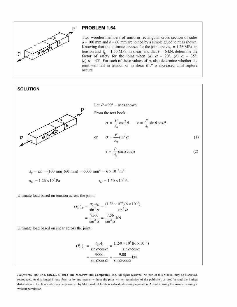
PROPRIETARY MATERIAL. © 2012 The McGraw-Hill Companies, Inc. All rights reserved. No part of this Manual may be displayed,
reproduced, or distributed in any form or by any means, without the prior written permission of the publisher, or used beyond the limited
distribution to teachers and educators permitted by McGraw-Hill for their individual course preparation. A student using this manual is using it
without permission.
PROBLEM 1.64
Two wooden members of uniform rectangular cross section of sides a = 100 mm and b = 60 mm are joined by a simple glued joint as shown. Knowing that the ultimate stresses for the joint are 1.26 MPaUσ = in tension and 1.50 MPaτ =U in shear, and that P = 6 kN, determine the factor of safety for the joint when (a) α = 20°, (b) α = 35°, (c) α = 45°. For each of these values of α, also determine whether the joint will fail in tension or in shear if P is increased until rupture occurs.
SOLUTION
Let 90θ α= ° − as shown.
From the text book:
2
0 0
cos sin cosσ θ τ θ θ= =P P
A A
or 2
0
sinσ α= P
A (1)
0
sin cosP
Aτ α α= (2)
2 3 20 (100 mm)(60 mm) 6000 mm 6 10 m−= = = = ×A ab
61.26 10 Paσ = ×U 61.50 10 Paτ = ×U
Ultimate load based on tension across the joint:
6 30
2 2
2 2
(1.26 10 )(6 10 )( )
sin sin7560 7.56
kNsin sin
UU
AP σ
σα α
α α
−× ×= =
= =
Ultimate load based on shear across the joint:
6 30 (1.50 10 )(6 10 )
( )sin cos sin cos
9000 9.00kN
sin cos sin cos
UU
AP τ
τα α α α
α α α α
−× ×= =
= =

PROPRIETARY MATERIAL. © 2012 The McGraw-Hill Companies, Inc. All rights reserved. No part of this Manual may be displayed,
reproduced, or distributed in any form or by any means, without the prior written permission of the publisher, or used beyond the limited
distribution to teachers and educators permitted by McGraw-Hill for their individual course preparation. A student using this manual is using it
without permission.
PROBLEM 1.64 (Continued)
(a) 2
7.5620 : ( ) 64.63 kN
sin 209.00
( ) 28.00 kNsin 20 cos 20
U
U
P
P
σ
τ
α = ° = =°
= = =° °
The smaller value governs. The joint will fail in shear and 28.00 kN.UP =
28.00
. .6
= =UPF S
P . . 4.67F S =
(b) 2
7.5635 : ( ) 22.98 kN
sin 359.00
( ) 19.155 kNsin 35 cos35
U
U
P
P
σ
τ
α = ° = =°
= =° °
The joint will fail in shear and 19.155 kN.UP =
19.155
. .6
UPF S
P= = . . 3.19F S =
(c) 2
7.5645 : ( ) 15.12 kN
sin 459.00
( ) 18.00 kNsin 45 cos 45
U
U
P
P
σ
τ
α = ° = =°
= =° °
The joint will fail in tension and 15.12 kN.UP =
15.12
. .6
UPF S
P= = . . 2.52F S =

PROPRIETARY MATERIAL. © 2012 The McGraw-Hill Companies, Inc. All rights reserved. No part of this Manual may be displayed,
reproduced, or distributed in any form or by any means, without the prior written permission of the publisher, or used beyond the limited
distribution to teachers and educators permitted by McGraw-Hill for their individual course preparation. A student using this manual is using it
without permission.
PROBLEM 1.65
Member ABC, which is supported by a pin and bracket at C and a cable BD, was designed to support the 16-kN load P as shown. Knowing that the ultimate load for cable BD is 100 kN, determine the factor of safety with respect to cable failure.
SOLUTION
Use member ABC as a free body, and note that member BD is a two-force member.
0 : ( cos 40 )(1.2) ( sin 40 )(0.6)
( cos30 )(0.6)
( sin 30 )(0.4) 0
1.30493 0.71962 0
c
BD
BD
BD
M P P
F
F
P F
Σ = ° + °− °− ° =
− =
3 3
3
3
3
1.81335 (1.81335)(16 10 ) 29.014 10 N
100 10 N
100 10. .
29.014 10
BD
U
U
BD
F P
F
FF S
F
= = × = ×
= ×
×= =×
. . 3.45=F S

PROPRIETARY MATERIAL. © 2012 The McGraw-Hill Companies, Inc. All rights reserved. No part of this Manual may be displayed,
reproduced, or distributed in any form or by any means, without the prior written permission of the publisher, or used beyond the limited
distribution to teachers and educators permitted by McGraw-Hill for their individual course preparation. A student using this manual is using it
without permission.
PROBLEM 1.66
The 2000-lb load can be moved along the beam BD to any position between stops at E and F. Knowing that all 6σ = ksi for the steel used in rods AB and CD, determine where the stops should be placed if the permitted motion of the load is to be as large as possible.
SOLUTION
Permitted member forces:
2
max all
2
max all
1: ( ) (6)
4 2
1.17810 kips
5: ( ) (6)
4 8
1.84078 kips
AB AB
CD CD
AB F A
CD F A
πσ
πσ
= =
=
= =
=
Use member BEFD as a free body.
2000 lb 2.000 kips= =P
0 : (60) (60 x ) 0
60 (60)(1.17810)60 x
2.000
Σ = − + − =
− = =
D AB E
ABE
M F P
F
P
35.343= x 24.7 in.=E
0 : 60 x 0Σ = − =B CD FM F P
60 (60)(1.84078)
x2.000
= =CDF
F
P x 55.2 in.=F

PROPRIETARY MATERIAL. © 2012 The McGraw-Hill Companies, Inc. All rights reserved. No part of this Manual may be displayed,
reproduced, or distributed in any form or by any means, without the prior written permission of the publisher, or used beyond the limited
distribution to teachers and educators permitted by McGraw-Hill for their individual course preparation. A student using this manual is using it
without permission.
PROBLEM 1.67
Knowing that a force P of magnitude 750 N is applied to the pedal shown, determine (a) the diameter of the pin at C for which the average shearing stress in the pin is 40 MPa, (b) the corresponding bearing stress in the pedal at C, (c) the corresponding bearing stress in each support bracket at C.
SOLUTION
Draw free body diagram of BCD. Since BCD is a 3-force member, the reaction at C is directed toward Point E, the intersection of the lines of action of the other two forces.
From geometry, 2 2300 125 325 mm= + =CE
125
0 : 0 2.6 (2.6)(750) 1950 N325
+ Σ = − = = = =↑ yF C P C P
(a) 1 1
32 2pin 2 6
pin pin4
2 (2)(1950)5.57 10 m
(40 10 )πτπτ π
−= = = = = ××
C C Cd
A d 5.57 mm=d
(b) 63 3
195038.9 10 Pa
(5.57 10 )(9 10 )σ − −= = = = ×
× ×bb
C C
A dt 38.9 MPaσ =b
(c) 1
623 3
195035.0 10 Pa
2 (2)(5.57 10 )(5 10 )σ − −= = = = ×
× ×bb
C C
A dt 35.0 MPaσ =b

PROPRIETARY MATERIAL. © 2012 The McGraw-Hill Companies, Inc. All rights reserved. No part of this Manual may be displayed,
reproduced, or distributed in any form or by any means, without the prior written permission of the publisher, or used beyond the limited
distribution to teachers and educators permitted by McGraw-Hill for their individual course preparation. A student using this manual is using it
without permission.
PROBLEM 1.68
A force P is applied as shown to a steel reinforcing bar that has been embedded in a block of concrete. Determine the smallest length L for which the full allowable normal stress in the bar can be developed. Express the result in terms of the diameter d of the bar, the allowable normal stress allσ in the steel, and the average allowable bond stress allτ between the concrete and the cylindrical surface of the bar. (Neglect the normal stresses between the concrete and the end of the bar.)
SOLUTION
For shear,
all all
πτ τ π
== =
A dL
P A dL
For tension, 2
2all all
4
4
π
πσ σ
=
= =
A d
P A d
Equating, 2all all 4
πτ π σ=dL d
Solving for L, min all all/4σ τ=L d

PROPRIETARY MATERIAL. © 2012 The McGraw-Hill Companies, Inc. All rights reserved. No part of this Manual may be displayed,
reproduced, or distributed in any form or by any means, without the prior written permission of the publisher, or used beyond the limited
distribution to teachers and educators permitted by McGraw-Hill for their individual course preparation. A student using this manual is using it
without permission.
PROBLEM 1.69
The two portions of member AB are glued together along a plane forming an angle θ with the horizontal. Knowing that the ultimate stress for the glued joint is 2.5 ksi in tension and 1.3 ksi in shear, determine the range of values of θ for which the factor of safety of the members is at least 3.0.
SOLUTION
20 (2.0)(1.25) 2.50 in.
2.4 kips
( . .) 7.2 kipsU
A
P
P F S P
= =
== =
Based on tensile stress:
2
0
02
cos
(2.5)(2.50)cos 0.86806
7.2
σ θ
σθ
=
= = =
UU
U
U
P
A
A
P
cos 0.93169θ = 21.3θ = ° 21.3θ > °
Based on shearing stress: 0 0
sin cos sin 22
τ θ θ θ= =U UU
P P
A A
02 (2)(2.50)(1.3)sin 2 0.90278
7.2
τθ = = =U
U
A
P
2 64.52θ = ° 32.3θ = ° 32.3θ < °
Hence, 21.3 32.3θ° < < °

PROPRIETARY MATERIAL. © 2012 The McGraw-Hill Companies, Inc. All rights reserved. No part of this Manual may be displayed,
reproduced, or distributed in any form or by any means, without the prior written permission of the publisher, or used beyond the limited
distribution to teachers and educators permitted by McGraw-Hill for their individual course preparation. A student using this manual is using it
without permission.
PROBLEM 1.70
The two portions of member AB are glued together along a plane forming an angle θ with the horizontal. Knowing that the ultimate stress for the glued joint is 2.5 ksi in tension and 1.3 ksi in shear, determine (a) the value of θ for which the factor of safety of the member is maximum, (b) the corresponding value of the factor of safety. (Hint: Equate the expressions obtained for the factors of safety with respect to normal stress and shear.)
SOLUTION
20 (2.0)(1.25) 2.50 inA = =
At the optimum angle, ( . .) ( . .)σ τ=F S F S
Normal stress: 02, 2
0
coscos
σσ
σ θθ
= ∴ = UU
APP
A
0,2
( . .)cos
σσ
σθ
= = UU APF S
P P
Shearing stress: 0,
0
0,
sin cossin cos
( . .)sin cos
UU
UU
APP
A
APF S
P P
τ
ττ
ττ θ θ
θ θ
τθ θ
= ∴ =
= =
Equating: 0 02 sin coscos
σ τθ θθ
=U UA A
PP
Solving: sin 1.3
tan 0.520cos 2.5
θ τθθ σ
= = = =U
U
(a) opt 27.5θ = °
(b) 02 2
(12.5)(2.50)7.94 kips
cos cos 27.5U
UA
Pσ
θ= = =
°
7.94
. .2.4
= =UPF S
P . . 3.31=F S