2301a speed control with ma speed setting input · manual 02302 2301a speed control with ma speed...
TRANSCRIPT

Installation and Operation Manual
2301A Speed Control with mA Speed Setting Input
Manual 02302 (Revision B)
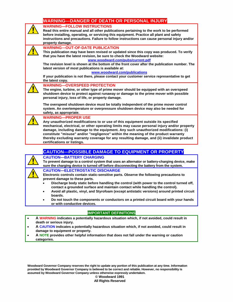
WARNING—DANGER OF DEATH OR PERSONAL INJURY
WARNING—FOLLOW INSTRUCTIONS Read this entire manual and all other publications pertaining to the work to be performed before installing, operating, or servicing this equipment. Practice all plant and safety instructions and precautions. Failure to follow instructions can cause personal injury and/or property damage.
WARNING—OUT-OF-DATE PUBLICATION This publication may have been revised or updated since this copy was produced. To verify that you have the latest revision, be sure to check the Woodward website:
www.woodward.com/pubs/current.pdf The revision level is shown at the bottom of the front cover after the publication number. The latest version of most publications is available at:
www.woodward.com/publications If your publication is not there, please contact your customer service representative to get the latest copy.
WARNING—OVERSPEED PROTECTION The engine, turbine, or other type of prime mover should be equipped with an overspeed shutdown device to protect against runaway or damage to the prime mover with possible personal injury, loss of life, or property damage. The overspeed shutdown device must be totally independent of the prime mover control system. An overtemperature or overpressure shutdown device may also be needed for safety, as appropriate.
WARNING—PROPER USE Any unauthorized modifications to or use of this equipment outside its specified mechanical, electrical, or other operating limits may cause personal injury and/or property damage, including damage to the equipment. Any such unauthorized modifications: (i) constitute "misuse" and/or "negligence" within the meaning of the product warranty thereby excluding warranty coverage for any resulting damage, and (ii) invalidate product certifications or listings.
CAUTION—POSSIBLE DAMAGE TO EQUIPMENT OR PROPERTY
CAUTION—BATTERY CHARGING To prevent damage to a control system that uses an alternator or battery-charging device, make sure the charging device is turned off before disconnecting the battery from the system.
CAUTION—ELECTROSTATIC DISCHARGE Electronic controls contain static-sensitive parts. Observe the following precautions to prevent damage to these parts. • Discharge body static before handling the control (with power to the control turned off,
contact a grounded surface and maintain contact while handling the control). • Avoid all plastic, vinyl, and Styrofoam (except antistatic versions) around printed circuit
boards. • Do not touch the components or conductors on a printed circuit board with your hands
or with conductive devices.
IMPORTANT DEFINITIONS • A WARNING indicates a potentially hazardous situation which, if not avoided, could result in
death or serious injury. • A CAUTION indicates a potentially hazardous situation which, if not avoided, could result in
damage to equipment or property. • A NOTE provides other helpful information that does not fall under the warning or caution
categories. Woodward Governor Company reserves the right to update any portion of this publication at any time. Information provided by Woodward Governor Company is believed to be correct and reliable. However, no responsibility is assumed by Woodward Governor Company unless otherwise expressly undertaken.
© Woodward 1991 All Rights Reserved
Manual 02302 2301A Speed Control with mA Speed Setting Input
Woodward i
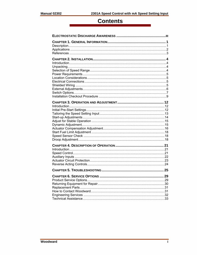
Contents
ELECTROSTATIC DISCHARGE AWARENESS ..................................................III CHAPTER 1. GENERAL INFORMATION........................................................... 1 Description..............................................................................................................1 Applications ............................................................................................................2 References .............................................................................................................3 CHAPTER 2. INSTALLATION.......................................................................... 4 Introduction.............................................................................................................4 Unpacking...............................................................................................................4 Selection of Speed Range......................................................................................4 Power Requirements..............................................................................................5 Location Considerations.........................................................................................5 Electrical Connections............................................................................................5 Shielded Wiring ......................................................................................................5 External Adjustments..............................................................................................6 Switch Options........................................................................................................7 Installation Checkout Procedure ............................................................................9 CHAPTER 3. OPERATION AND ADJUSTMENT............................................... 12 Introduction...........................................................................................................12 Initial Pre-Start Settings........................................................................................12 Tailoring the Speed Setting Input .........................................................................13 Start-up Adjustments ............................................................................................14 Adjust for Stable Operation ..................................................................................15 Dynamic Adjustment.............................................................................................15 Actuator Compensation Adjustment.....................................................................16 Start Fuel Limit Adjustment ..................................................................................18 Speed Sensor Check ...........................................................................................18 Droop Adjustment.................................................................................................18 CHAPTER 4. DESCRIPTION OF OPERATION................................................. 21 Introduction...........................................................................................................21 Speed Control.......................................................................................................21 Auxiliary Inputs .....................................................................................................22 Actuator Circuit Protection....................................................................................23 Reverse Acting Controls.......................................................................................24 CHAPTER 5. TROUBLESHOOTING............................................................... 25 CHAPTER 6. SERVICE OPTIONS ................................................................. 29 Product Service Options.......................................................................................29 Returning Equipment for Repair...........................................................................30 Replacement Parts ...............................................................................................31 How to Contact Woodward...................................................................................31 Engineering Services ...........................................................................................32 Technical Assistance............................................................................................33
2301A Speed Control with mA Speed Setting Input Manual 02302
ii Woodward
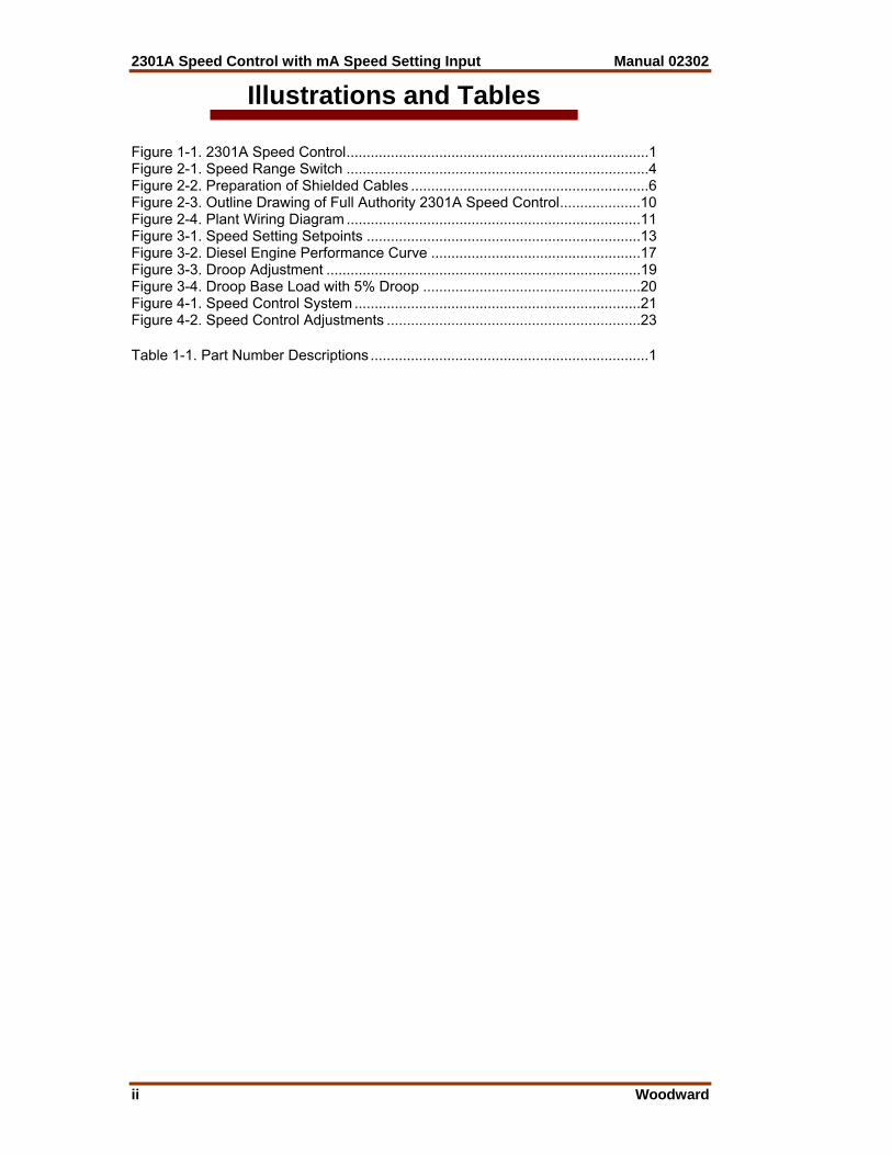
Illustrations and Tables Figure 1-1. 2301A Speed Control...........................................................................1 Figure 2-1. Speed Range Switch ...........................................................................4 Figure 2-2. Preparation of Shielded Cables ...........................................................6 Figure 2-3. Outline Drawing of Full Authority 2301A Speed Control....................10 Figure 2-4. Plant Wiring Diagram .........................................................................11 Figure 3-1. Speed Setting Setpoints ....................................................................13 Figure 3-2. Diesel Engine Performance Curve ....................................................17 Figure 3-3. Droop Adjustment ..............................................................................19 Figure 3-4. Droop Base Load with 5% Droop ......................................................20 Figure 4-1. Speed Control System .......................................................................21 Figure 4-2. Speed Control Adjustments ...............................................................23 Table 1-1. Part Number Descriptions .....................................................................1

Manual 02302 2301A Speed Control with mA Speed Setting Input
Woodward iii
Electrostatic Discharge Awareness All electronic equipment is static-sensitive, some components more than others. To protect these components from static damage, you must take special precautions to minimize or eliminate electrostatic discharges. Follow these precautions when working with or near the control. 1. Before doing maintenance on the electronic control, discharge the static
electricity on your body to ground by touching and holding a grounded metal object (pipes, cabinets, equipment, etc.).
2. Avoid the build-up of static electricity on your body by not wearing clothing
made of synthetic materials. Wear cotton or cotton-blend materials as much as possible because these do not store static electric charges as much as synthetics.
3. Keep plastic, vinyl, and Styrofoam materials (such as plastic or Styrofoam
cups, cup holders, cigarette packages, cellophane wrappers, vinyl books or folders, plastic bottles, and plastic ash trays) away from the control, the modules, and the work area as much as possible.
4. Do not remove the printed circuit board (PCB) from the control cabinet
unless absolutely necessary. If you must remove the PCB from the control cabinet, follow these precautions:
• Do not touch any part of the PCB except the edges. • Do not touch the electrical conductors, the connectors, or the
components with conductive devices or with your hands. • When replacing a PCB, keep the new PCB in the plastic antistatic
protective bag it comes in until you are ready to install it. Immediately after removing the old PCB from the control cabinet, place it in the antistatic protective bag.
CAUTION—ELECTROSTATIC DISCHARGE To prevent damage to electronic components caused by improper handling, read and observe the precautions in Woodward manual 82715, Guide for Handling and Protection of Electronic Controls, Printed Circuit Boards, and Modules.

2301A Speed Control with mA Speed Setting Input Manual 02302
iv Woodward
Manual 02302 2301A Speed Control with mA Speed Setting Input
Woodward 1
Chapter 1. General Information
Description The 2301A Full Authority Speed Control controls the speed or load of diesel or gas engines, or steam or gas turbines according to the demand of a process or a computer control signal of 4–20 mA or 1–5 Vdc. The control is housed in a sheet-metal chassis and consists of a single printed circuit board. All potentiometers are accessible from the front of the chassis. The 2301A Full Authority Speed Control provides control in the isochronous mode with droop available through an externally-wired potentiometer. The isochronous mode is used for constant speed of the controlled prime mover as long as it is able to satisfy the load. Isochronous is also used when load sharing with a Woodward load sensor.
Table 1-1. Part Number Descriptions
Supply Voltage Actuator Current
Speed Set Input Forward Reverse
10 to 40 dc 0–200 mA 4–20 mA 9905-144 9905-146 88-131 ac or
90-150 dc 0–200 mA 4–20 mA 9905-145 9905-147
10 to 40 dc 0–20 mA 4–20 mA 9905-194 88-131 ac or
90-150 dc 0–20 mA 4–20 mA 9905-195
10 to 40 dc 0–200 mA 1–5 Vdc 9905-148 9905-150 88-131 ac or
90-150 dc 0–200 mA 1–5 Vdc 9905-149 9905-151
10 to 40 dc 0–20 mA 1–5 Vdc 9905-794
Figure 1-1. 2301A Speed Control

2301A Speed Control with mA Speed Setting Input Manual 02302
2 Woodward
External droop is used for speed control as a function of load when a prime mover is operating on an infinite bus or when two or more prime movers are in parallel operation. Programmable Logic Control (PLC) is easily adapted to engine control with the use of the 4–20 mA speed-setting input. The low-limit setting can prevent engine shutdown, even with loss of the PLC signal. Reverse-acting controls allow the teaming of the electronic control with the ballhead backup/actuator feature found in the EGB or PG-EG governor/actuator. The 2301A system for a prime-mover requires: • A 2301A full authority electronic speed control • An external power source • A speed-sensing device (MPU) • A proportional actuator to position the fuel- or steam-metering device
Applications 2301A Full Authority Speed Controls are available for forward- or reverse-acting actuators. High voltage models accept 88 to 132 Vac or 90 to 150 Vdc. Low voltage models accept a 10 to 40 Vdc supply. A listing of applications and controls is provided in Table 1-1. Speed range is set on an internal dip switch, available inside the steel cover of the control. Speeds are set according to the sensor output frequency. The relationship between prime-mover speed and sensor-output frequency is expressed in the formula: Sensor Frequency in Hz equals the number of teeth on the speed-sensing gear times the revolutions per minute of the sensing gear, times the ratio of the engine speed to the sensing gear speed, divided by 60.
⎟⎟⎠
⎞⎜⎜⎝
⎛⎟⎠⎞
⎜⎝⎛
SpeedGear Sensing SpeedEngine x
60RPM x teeth of No. =Hz
Full Authority The Full Authority control is designed for use with a process sensor which provides a 4–20 mA or a 1–5 Vdc signal indicating the demand of the process, or with a computer circuit which indicates the amount of power or speed needed according to the program logic. The unit offers the features of a 2301A speed control operating with a signal converter. Combining the features of a signal converter with the speed control improves the efficiency and convenience of the control system. High and low limits may be used with the speed-setting signal to achieve special control conditions such as minimum output, load limiting, and control in the absence of the 1–5 Vdc or 4–20 mA signal usually used to set the speed reference.
Manual 02302 2301A Speed Control with mA Speed Setting Input
Woodward 3
Reverse Acting Reverse acting 2301A Full Authority Speed Controls will operate Woodward EGB governor/actuators. In reverse-acting systems, the actuator calls for more fuel when the actuator current decreases. Complete loss of signal to the actuator will drive the actuator to full fuel. This allows a backup mechanical-ballhead governor to take control rather than shut down the prime mover as would a direct-acting system. External wiring connections for reverse-acting controls are identical to those for direct-acting controls. However, changes must be made to the printed circuit board should a control need to operate the opposite type of actuator. Contact Woodward should it be necessary to change the type of control. Changing the supply voltage rating requires exchanging the unit for the properly rated control.
References The following Woodward publications contain additional product or installation information on speed controls and related components. Publication ordering information is provided on the back cover of this manual. Manuals 25070 Electronic Control Installation Guide 82510 Magnetic Pickups & Proximity Switches for Electronic Controls Product Specifications 82516 EG-3P/6P/10P Actuator 82575 EGB-1P/2P Governor/Actuator 02301 2301A Speed Control with 4-20 mA input Woodward Application Engineers will assist you in the selection of the correct control and answer questions.
2301A Speed Control with mA Speed Setting Input Manual 02302
4 Woodward
Chapter 2. Installation
Introduction This chapter contains general installation instructions for the 2301A Full Authority Speed Control. Power requirements, environmental precautions, and location considerations are included to determine the best location for the control. Additional information includes unpacking instructions, electrical connections, and an installation check-out procedure.
Unpacking Before handling the control, read the Electrostatic Discharge Awareness section. Be careful when unpacking the electronic control. Check the control for signs of damage such as bent or dented panels, scratches, and loose or broken parts. Notify the shipper of any damage.
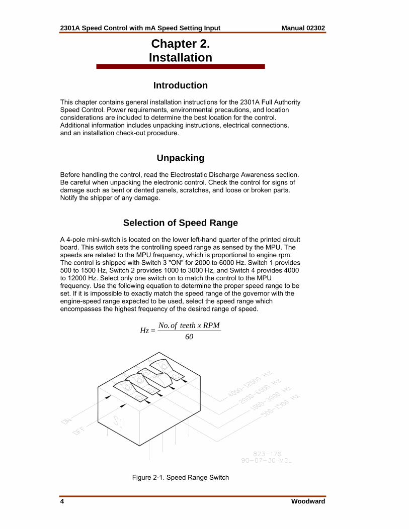
Selection of Speed Range A 4-pole mini-switch is located on the lower left-hand quarter of the printed circuit board. This switch sets the controlling speed range as sensed by the MPU. The speeds are related to the MPU frequency, which is proportional to engine rpm. The control is shipped with Switch 3 "ON" for 2000 to 6000 Hz. Switch 1 provides 500 to 1500 Hz, Switch 2 provides 1000 to 3000 Hz, and Switch 4 provides 4000 to 12000 Hz. Select only one switch on to match the control to the MPU frequency. Use the following equation to determine the proper speed range to be set. If it is impossible to exactly match the speed range of the governor with the engine-speed range expected to be used, select the speed range which encompasses the highest frequency of the desired range of speed.
60RPM x teeth of No.=Hz
Figure 2-1. Speed Range Switch
Manual 02302 2301A Speed Control with mA Speed Setting Input
Woodward 5
Power Requirements High and low voltage models of 2301A Full Authority Speed Controls are available. Low voltage models require a supply of 10 to 40 Vdc, 12 W. High Voltage models require a supply of 88 to 120 Vac or 90 to 150 Vdc., 12 W. AC supply may be 50 to 400 Hz. If a battery is used for operating power, an alternator or other battery charging device is necessary to maintain a stable supply voltage.
CAUTION—BATTERY To prevent damage to the control, make sure that the alternator or other battery-charging device is not connected to the control when the battery is disconnected from the control.
Location Considerations Consider these requirements when selecting the mounting location: • Adequate ventilation for cooling • Space for servicing and repair • Protection from direct exposure to water or to a condensation-prone
environment. • Protection from high-voltage or high-current devices, or devices which
produce electromagnetic interference. • Protection from excessive vibration. • An ambient operating temperature range of –40 to +85 °C (–40 to +185 °F). Do not mount the control on the engine.
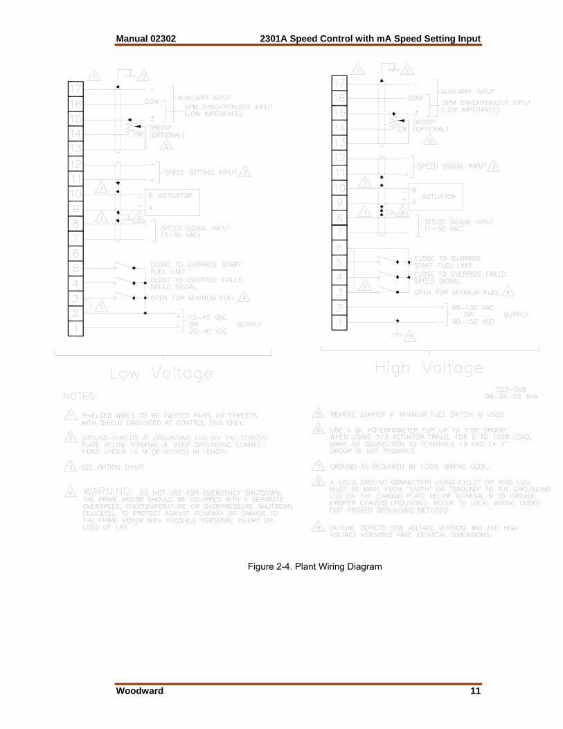
Electrical Connections External wiring connections and shielding requirements for a typical control installation are shown in the plant wiring diagram, Figure 2-4. These wiring connections and shielding requirements are explained in the balance of this section.
Shielded Wiring All shielded cable must be twisted conductor pairs. Do not attempt to tin (solder) the braided shield. All signal lines should be shielded to prevent picking up stray signals from adjacent equipment. Connect the shields to the grounding lug on the chassis plate below Terminal 9. Keep grounding connections under 150 mm (6 inches) length. A solid ground connection must be made from "earth" or ground to the grounding lug to provide proper chassis grounding. Refer to local wiring codes for proper grounding methods. Wire exposed beyond the shield should be as short as possible, not exceeding 150 mm (6 inches). The other end of the shields must be left open and insulated from any other conductor. Do not run shielded signal wires with other wires carrying large currents. See Application Note 50532, EMI Control for Electronic Governing Systems, for more information.
2301A Speed Control with mA Speed Setting Input Manual 02302
6 Woodward
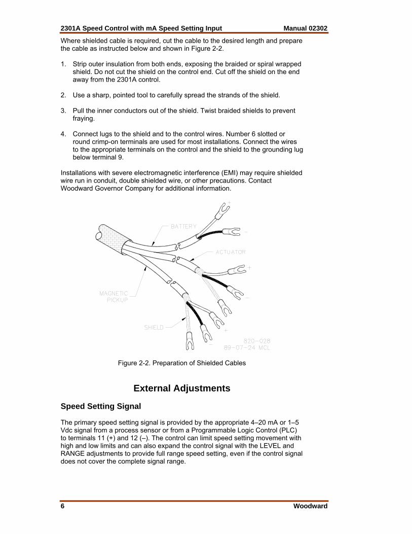
Where shielded cable is required, cut the cable to the desired length and prepare the cable as instructed below and shown in Figure 2-2. 1. Strip outer insulation from both ends, exposing the braided or spiral wrapped
shield. Do not cut the shield on the control end. Cut off the shield on the end away from the 2301A control.
2. Use a sharp, pointed tool to carefully spread the strands of the shield. 3. Pull the inner conductors out of the shield. Twist braided shields to prevent
fraying. 4. Connect lugs to the shield and to the control wires. Number 6 slotted or
round crimp-on terminals are used for most installations. Connect the wires to the appropriate terminals on the control and the shield to the grounding lug below terminal 9.
Installations with severe electromagnetic interference (EMI) may require shielded wire run in conduit, double shielded wire, or other precautions. Contact Woodward Governor Company for additional information.
Figure 2-2. Preparation of Shielded Cables
External Adjustments Speed Setting Signal The primary speed setting signal is provided by the appropriate 4–20 mA or 1–5 Vdc signal from a process sensor or from a Programmable Logic Control (PLC) to terminals 11 (+) and 12 (–). The control can limit speed setting movement with high and low limits and can also expand the control signal with the LEVEL and RANGE adjustments to provide full range speed setting, even if the control signal does not cover the complete signal range.
Manual 02302 2301A Speed Control with mA Speed Setting Input
Woodward 7
Droop Potentiometer A 2K potentiometer may be connected to provide a maximum of about 8% droop. Connect the potentiometer (ccw) to terminal 15, (cw) to terminal 14, and wiper to terminal 13. If droop is not desired, make no connections to terminals 13 and 14.
Switch Options Minimum Fuel Contact The minimum-fuel contact between terminals 2 and 3 on the low-power models and 3 and 6 on the high-power models is intended as an optional means for a normal shutdown of the prime mover. The contact is connected as shown on the plant wiring diagram for the particular control. If a minimum fuel contact is not used, the terminals must be permanently jumpered.
WARNING—EMERGENCY STOP Do NOT use the minimum-fuel contact as a part of any emergency stop sequence. The emergency may be caused by a governor or actuator malfunction which would also cause a malfunction of the minimum-fuel feature. Use of the minimum-fuel contact for an emergency stop sequence could cause overspeed of the prime mover and mechanical damage and personal injury, including death. Failed Speed Signal Override Circuits in the 2301A Speed Control constantly monitor the signal from the MPU. Should this signal be below a minimum threshold the control sends a minimum fuel signal to the actuator. Before start-up of the prime mover, the speed signal is nonexistent, activating the failed-speed-signal circuit. On units with cranking motors, the cranking speed is usually sufficient to provide a speed signal, so an override contact is not needed for starting. On some steam turbine systems, the Close for Override of Failed Speed Signal contact must be closed to allow the actuator to open and provide steam for starting. The failed-speed-signal override switch should be a momentary switch so the failed-speed-sensor circuit will be enabled after start up. Start Fuel Limit Override Connect a single-pole, single-throw switch to terminal 5 as shown on the appropriate plant-wiring diagram. Close the contact to override the Start Fuel Limit. When closed, 10 to 40 Vdc is applied to terminal 5, and the Start Fuel Limit will not effect actuator position.
2301A Speed Control with mA Speed Setting Input Manual 02302
8 Woodward
Actuator Output The actuator wires connect to terminals 9 (+) and 10 (–). Use shielded wires with the shield connected to the grounded post on the panel. Do not connect the shield to the actuator or to any other point. The shield must have continuity the entire distance to the actuator and must be insulated from all other conductors.
NOTE Electromagnetic Interference (EMI) can be an intermittent condition. Improperly shielded installations can provide good control for a while and then cause problems. For this reason it is important to be sure all shields are properly installed. Speed Setting Signal The speed setting signal received at terminals 11 and 12 is capable of providing full speed setting of the engine from idle to high limit. The Rated Speed/Low Limit setting can set the minimum speed which can be attained by the speed setting signal. This can be as high as rated or the setting can be turned completely out of the way allowing full authority to the speed setting signal. Speed and Phase Matching with an SPM-A Synchronizer Connect the SPM-A (optional equipment) wires to terminals 15 (±) and 16 (com). Use shielded wire and connect the shield to the ground. Auxiliary Input Terminals 17 (–) and 15 (+) are used for auxiliary input from a load sensor. Use of the load sensor and parallel lines allow the 2301A Speed Control to be used in isochronous load-sharing circuits. If the load sensor is not used, droop must be used to share load. (An exception is a multiple engine installation in which one engine is operated isochronously and all other engines are operated in droop.) Speed Sensor Connect a speed-sensing device (a magnetic pickup/MPU is normally used) to terminals 8 and 7. No polarity is observed. Use shielded wire and connect the shield only at the 2301A control. The shield must have continuity the entire distance to the MPU. The shield is to be insulated from all other conductors and from the MPU.
Manual 02302 2301A Speed Control with mA Speed Setting Input
Woodward 9
Installation Checkout Procedure When the installation is completed perform the following check-out procedure before beginning the start-up adjustments in Chapter 3. 1. Visual Inspection: a. Check the linkage between the actuator and the prime mover for
looseness or binding. Refer to the appropriate actuator manual, and Manual 25070, Electronic Control Installation Guide, for additional information on linkage.
WARNING—MINIMUM FUEL POSITION The actuator lever should be near, but not at, the minimum position when the fuel or steam rack is at the minimum position. This could avoid a dangerous condition caused by an engine which will not shut down. b. Check for correct wiring according the plant wiring diagram. c. Check for broken terminals and loose terminal screws. Make sure all
terminal lugs are carefully and correctly installed. (Incorrectly installed crimp-on terminals can cause governor failure.)
d. Check the speed sensor (MPU) for visible damage. Check the
clearance between the gear and the sensor, and adjust if necessary. See Manual 82510, Magnetic Pickups & Proximity Switches for Electronic Controls.
2. Check for Grounds. With the power off, check for grounds by measuring the resistance between
each terminal and the grounding bolt located below terminal 9. Terminals 1 and 2 are power-input terminals. Either of these terminals may be grounded in accordance with local codes or through other equipment powered from the same supply. If either is grounded, a high resistance to ground will be evident at terminals 1 through 5 on low voltage models and terminals 1 through 4 on high voltage models. grounds present on these terminals will not normally affect operation, unless they interfere with the input power or switching logic. Grounds on terminals 7 through 17, detected by readings other than infinity, should be located and removed.

2301A Speed Control with mA Speed Setting Input Manual 02302
10 Woodward
LOW VOLTAGE MODEL
HIGH VOLTAGE MODEL
Figure 2-3. Outline Drawing of Full Authority 2301A Speed Control
Manual 02302 2301A Speed Control with mA Speed Setting Input
Woodward 11
Figure 2-4. Plant Wiring Diagram
2301A Speed Control with mA Speed Setting Input Manual 02302
12 Woodward
Chapter 3. Operation and Adjustment
Introduction This chapter contains information on control calibration. It includes initial pre-start up and start up settings and adjustments.
WARNING—OVERSPEED Overspeed with resultant equipment damage, personal injury, or death is possible when setting up a control system. Read this entire procedure before starting the prime mover for the first time.
Initial Pre-Start Settings 1. RESET—Set at mid-position (1-turn pot). 2. GAIN—Set at mid-position (1-turn pot). 3. RATED SPEED/LOW LIMIT—Set at minimum (fully counterclockwise)
(10-turn pot). 4. HIGH LIMIT—Set at maximum (fully clockwise) (1-turn pot). 5. DROOP—Set optional external droop (if used) at minimum (fully
counterclockwise) (1-turn pot). 6. ACTUATOR COMPENSATION—(1-turn pot). a. DIESEL, GAS TURBINE, FUEL-INJECTED GASOLINE PRIME
MOVERS: Set the ACTUATOR COMPENSATION potentiometer at 2 on the 0 to 10 scale.
b. CARBURETED GAS OR GASOLINE or STEAM TURBINE PRIME
MOVERS: Set the ACTUATOR COMPENSATION potentiometer at 6 on the 0 to 10 scale.
7. LEVEL—Set potentiometer at minimum, (fully counterclockwise) (25-turn
pot). 8. RANGE—Set potentiometer fully clockwise (25-turn pot). 9. START FUEL LIMIT—Set at maximum (fully clockwise) (1-turn pot). 10. Be sure the actuator is connected to terminals 9 (+) and 10 (–). (For bench
test purposes, a 35–40 Ω, 3 W minimum resistor may be used instead of an actuator.)
NOTE Range and Level adjustment potentiometers are 25-turn with slip clutches. Rate speed/low limit adjustment is 10-turn with mechanical positive stops.
Manual 02302 2301A Speed Control with mA Speed Setting Input
Woodward 13
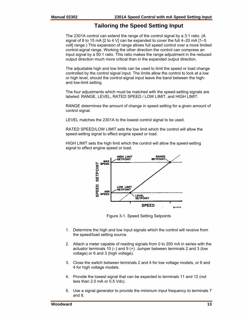
Tailoring the Speed Setting Input The 2301A control can extend the range of the control signal by a 3:1 ratio. (A signal of 8 to 15 mA [2 to 4 V] can be expanded to cover the full 4–20 mA [1–5 volt] range.) This expansion of range allows full speed control over a more limited control-signal range. Working the other direction the control can compress an input signal by a 50:1 ratio. This ratio makes the range adjustment in the reduced output direction much more critical than in the expanded output direction. The adjustable high and low limits can be used to limit the speed or load change controlled by the control signal input. The limits allow the control to lock at a low or high level, should the control-signal input leave the band between the high- and low-limit setting. The four adjustments which must be matched with the speed-setting signals are labeled: RANGE, LEVEL, RATED SPEED / LOW LIMIT, and HIGH LIMIT. RANGE determines the amount of change in speed setting for a given amount of control signal. LEVEL matches the 2301A to the lowest control signal to be used. RATED SPEED/LOW LIMIT sets the low limit which the control will allow the speed-setting signal to effect engine speed or load. HIGH LIMIT sets the high limit which the control will allow the speed-setting signal to effect engine speed or load.
Figure 3-1. Speed Setting Setpoints 1. Determine the high and low input signals which the control will receive from
the speed/load setting source. 2. Attach a meter capable of reading signals from 0 to 200 mA in series with the
actuator terminals 10 (–) and 9 (+). Jumper between terminals 2 and 3 (low voltage) or 6 and 3 (high voltage).
3. Close the switch between terminals 2 and 4 for low voltage models, or 6 and
4 for high voltage models. 4. Provide the lowest signal that can be expected to terminals 11 and 12 (not
less than 2.0 mA or 0.5 Vdc). 5. Use a signal generator to provide the minimum input frequency to terminals 7
and 8.
2301A Speed Control with mA Speed Setting Input Manual 02302
14 Woodward
6. Adjust the Level pot until the signal at terminals 9 and 10 just starts to drop. 7. Increase the control signal to the maximum signal that can be expected (no
more than 20 mA or 5 Vdc). 8. Use a signal generator to provide the maximum input frequency. 9. Adjust the Range pot until the signal at terminals 9 and 10 just starts to
change. 10. Repeat steps 4 through 9 until additional adjustment is not needed. 11. Open the switch between terminals 2 and 4 for low voltage models, or 6 and
4 for high voltage models. 12. Set the speed signal at the lowest limit. 13. Use a signal generator to provide a signal at the low-limit frequency. Adjust
the Low Limit potentiometer until the signal at terminals 9 and 10 just starts to change.
14. Set the speed signal at the highest limit. 15. Use a signal generator to provide a signal at the high-limit frequency. Adjust
the High Limit potentiometer until the signal at terminals 9 and 10 just starts to drop. Then turn the adjustment clockwise until the signal increases.
Start-up Adjustments 1. Complete the installation checkout procedure in Section 3, and the initial
prestart settings above. Do not move the Level, Range, or High and Low limit settings.
2. If the external droop feature is being used it should already be set at
isochronous, fully counterclockwise. 3. Apply input power to the control. 4. Set the signal generator for the frequency of the speed sensor at rated
speed, and connect it to terminals 7 and 8. (The rated speed frequency in Hz equals the rated engine speed in rpm times the number of teeth on the speed sensing gear, times the ratio of engine speed to speed-sensing-gear speed, divided by 60.) Connect a dc analog voltmeter to terminals 9 (+) and 10 (–) to read actuator voltage. Actuator must be connected.
5. Close the override Start Fuel Limit, Override Failed Speed Signal, and the
Open for Minimum Fuel switches. 6. Attach an appropriate 4 to 20 mA or 1 to 5 Vdc source to the speed-setting
input terminals 11 and 12. Apply the minimum current or voltage to the terminals and measure the actuator output signal from terminals 9 and 10. The output should be at less than 10 mV.
7. Remove the signal generator from terminals 7 and 8 and attach the magnetic
pickup leads to these terminals. Install a frequency sensor across terminals 7 and 8 before proceeding.
Manual 02302 2301A Speed Control with mA Speed Setting Input
Woodward 15
8. Open the "Close to Override Start Fuel Limit" contacts. Open the "Close to Override Failed Speed Signal" contacts. Open the "Open for Minimum Fuel" contacts.
9. Check the speed sensor. Minimum voltage required from the speed sensor to operate the electronic
control is 1.0 Vrms, measured at cranking speed or the lowest controlling speed. For this test, measure the voltage while cranking, with the speed sensor connected to the control. Before cranking, be sure to prevent the prime mover from starting. At 5% of the lower value of the control's speed range, the failed speed-sensing circuit is cleared. For example 100 Hz is required on the 2000 to 6000 Hz speed range (2000 Hz x .05 = 100 Hz).
10. When the above test is completed, close the "Open for Minimum Fuel"
contacts. This will put the 2301A in the "run" mode. The "Override Failed Speed Signal" and "Override Start Fuel Limit" contacts should be open during normal operation.
WARNING—START-UP Be prepared to make an emergency shutdown when starting the engine, turbine, or other type of prime mover, to protect against runaway or overspeed with possible personal injury, loss of life, or property damage.
Adjust for Stable Operation Start the engine with the minimum speed setting input (4 mA or 1 Vdc). Speed setting must be acceptable before proceeding to adjust for stable operation. If prime-mover operation is stable disturb the setting or the actuator position and allow the governor to return the engine to stable condition. (Gain and Reset Adjustments are explained in more detail on the following pages.) If the prime mover is hunting at a rapid rate, slowly decrease the gain (turn the potentiometer counterclockwise) until performance is stable. Adjusting the gain may cause a momentary speed change which can be minimized by turning the gain potentiometer slowly. If the prime mover is hunting at a slow rate, increase the RESET setting (turn the potentiometer clockwise) until the prime mover stabilizes. If increasing the RESET potentiometer setting does not stabilize the prime mover, it also may be necessary to either: • Slowly decrease the GAIN (turn the potentiometer counterclockwise) or • Slowly decrease the GAIN and increase the ACTUATOR
COMPENSATION.
Dynamic Adjustment The object of the GAIN AND RESET potentiometer adjustments is to obtain the optimum, or desired, stable prime-mover-speed response.
NOTE Adjusting the GAIN may cause momentary changes in speed which can be minimized by turning the GAIN potentiometer slowly.
2301A Speed Control with mA Speed Setting Input Manual 02302
16 Woodward
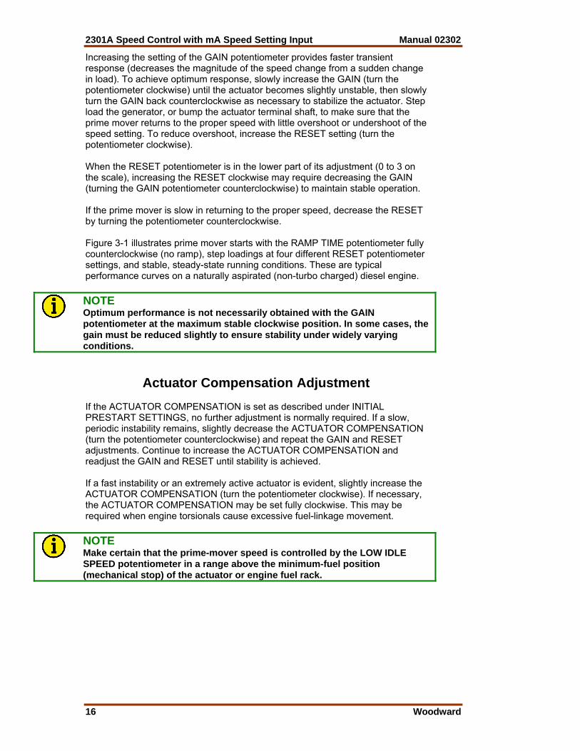
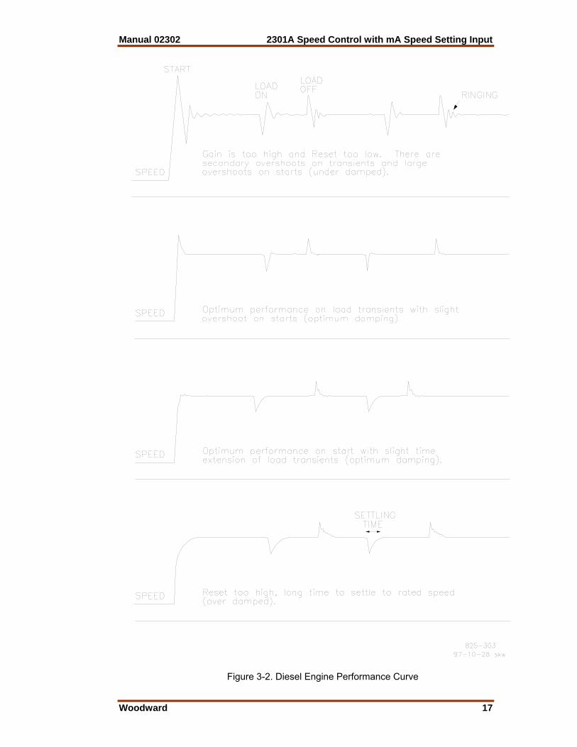
Increasing the setting of the GAIN potentiometer provides faster transient response (decreases the magnitude of the speed change from a sudden change in load). To achieve optimum response, slowly increase the GAIN (turn the potentiometer clockwise) until the actuator becomes slightly unstable, then slowly turn the GAIN back counterclockwise as necessary to stabilize the actuator. Step load the generator, or bump the actuator terminal shaft, to make sure that the prime mover returns to the proper speed with little overshoot or undershoot of the speed setting. To reduce overshoot, increase the RESET setting (turn the potentiometer clockwise). When the RESET potentiometer is in the lower part of its adjustment (0 to 3 on the scale), increasing the RESET clockwise may require decreasing the GAIN (turning the GAIN potentiometer counterclockwise) to maintain stable operation. If the prime mover is slow in returning to the proper speed, decrease the RESET by turning the potentiometer counterclockwise. Figure 3-1 illustrates prime mover starts with the RAMP TIME potentiometer fully counterclockwise (no ramp), step loadings at four different RESET potentiometer settings, and stable, steady-state running conditions. These are typical performance curves on a naturally aspirated (non-turbo charged) diesel engine.
NOTE Optimum performance is not necessarily obtained with the GAIN potentiometer at the maximum stable clockwise position. In some cases, the gain must be reduced slightly to ensure stability under widely varying conditions.
Actuator Compensation Adjustment If the ACTUATOR COMPENSATION is set as described under INITIAL PRESTART SETTINGS, no further adjustment is normally required. If a slow, periodic instability remains, slightly decrease the ACTUATOR COMPENSATION (turn the potentiometer counterclockwise) and repeat the GAIN and RESET adjustments. Continue to increase the ACTUATOR COMPENSATION and readjust the GAIN and RESET until stability is achieved. If a fast instability or an extremely active actuator is evident, slightly increase the ACTUATOR COMPENSATION (turn the potentiometer clockwise). If necessary, the ACTUATOR COMPENSATION may be set fully clockwise. This may be required when engine torsionals cause excessive fuel-linkage movement.
NOTE Make certain that the prime-mover speed is controlled by the LOW IDLE SPEED potentiometer in a range above the minimum-fuel position (mechanical stop) of the actuator or engine fuel rack.
Manual 02302 2301A Speed Control with mA Speed Setting Input
Woodward 17
Figure 3-2. Diesel Engine Performance Curve

2301A Speed Control with mA Speed Setting Input Manual 02302
18 Woodward
Start Fuel Limit Adjustment
NOTE Start-fuel limit is not recommended for use with reverse-acting controls. With loss of speed signal, the reverse acting control will position the actuator at the start-fuel level if the failed-speed-signal override is activated. Reverse-acting systems normally require the control to demand full fuel on loss of speed signal to allow the mechanical backup governor to control the system. The Start Fuel Limit can be deactivated by turning the potentiometer fully clockwise. With the prime mover operating at desired speed and no load, record the voltage across the actuator terminals 9 (+) and 10 (–). Shut down the prime mover and activate the Failed Speed Signal Override by closing the override contact. The voltage to the actuator should now be adjustable by the START FUEL LIMIT potentiometer. Set the actuator voltage about 30 percent higher than the voltage obtained at rated speed for forward-acting controls and 30 percent lower than rated speed voltage for reverse-acting controls. Remove the Failed Speed Signal Override contact if not required to start the prime mover. Start the prime mover and observe the start time, overshoot of speed setting, and exhaust smoke obtained. If the prime mover does not start, turn the START FUEL LIMIT potentiometer slightly clockwise until the prime mover starts. The START FUEL LIMIT may be adjusted as required to optimize the prime-mover starting characteristics. The fuel-limiting function is turned off automatically when the speed control takes over.
NOTE For prime movers not requiring start-fuel limiting, the START FUEL LIMIT function can be deactivated by turning the potentiometer fully clockwise.
Speed Sensor Check If the sensor is a magnetic pickup, measure the voltage across terminals 7 and 8 to be sure there is a minimum of 1.0 volts at cranking speed, and a maximum of 30 Vrms at rated speed. If the voltage exceeds 30 V, increase the gap of the speed sensor, and be sure that there is still a minimum of 1.0 V at cranking speed.
Droop Adjustment The amount of droop is not critical in many installations. If the engine needs to run in droop but the amount is not critical set the droop potentiometer in mid-position, then adjust load with the Rated Speed/Low Limit potentiometer or the speed setting signal.. When paralleled with an infinite bus, the generator frequency cannot change, and unless a load- sensing module is being used, the control must be in droop to maintain stable operation. With the droop potentiometer at mid-position, parallel the generator, then increase the Rated Speed/Low Limit potentiometer until the desired amount of load on the engine is achieved. Too much droop will cause the engine to overspeed should the load be suddenly lost. Excessive droop will also cause the engine to be sluggish in response to load changes.
Manual 02302 2301A Speed Control with mA Speed Setting Input
Woodward 19
Too little droop will cause instability, similar to that experienced with improperly adjusted GAIN and RESET. Units running against an isolated bus often need droop set to a particular level, to prevent excessive off speed when load changes. Droop is usually expressed as a percentage and calculated by the following formula:
% Droop= No Load Speed-Full Load SpeedNo Load Speed X 100
To set a specified amount of droop using an isolated bus for the load: 1. Set the droop potentiometer to mid-position. (Use a 2K potentiometer,
connected to terminal 14 (cw), 13 (wiper) and 15 (ccw). 2. Start the prime mover and adjust the SPEED SETTING INPUT SIGNAL for
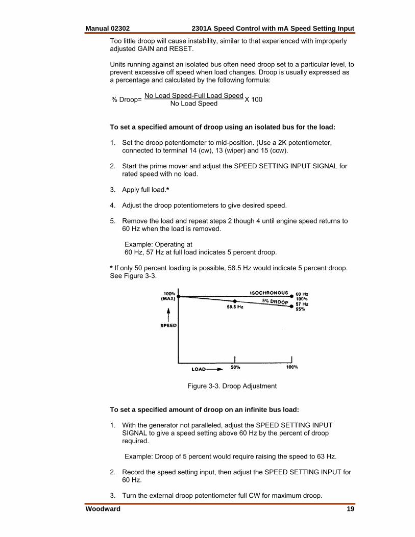
rated speed with no load. 3. Apply full load.* 4. Adjust the droop potentiometers to give desired speed. 5. Remove the load and repeat steps 2 though 4 until engine speed returns to
60 Hz when the load is removed. Example: Operating at 60 Hz, 57 Hz at full load indicates 5 percent droop. * If only 50 percent loading is possible, 58.5 Hz would indicate 5 percent droop. See Figure 3-3.
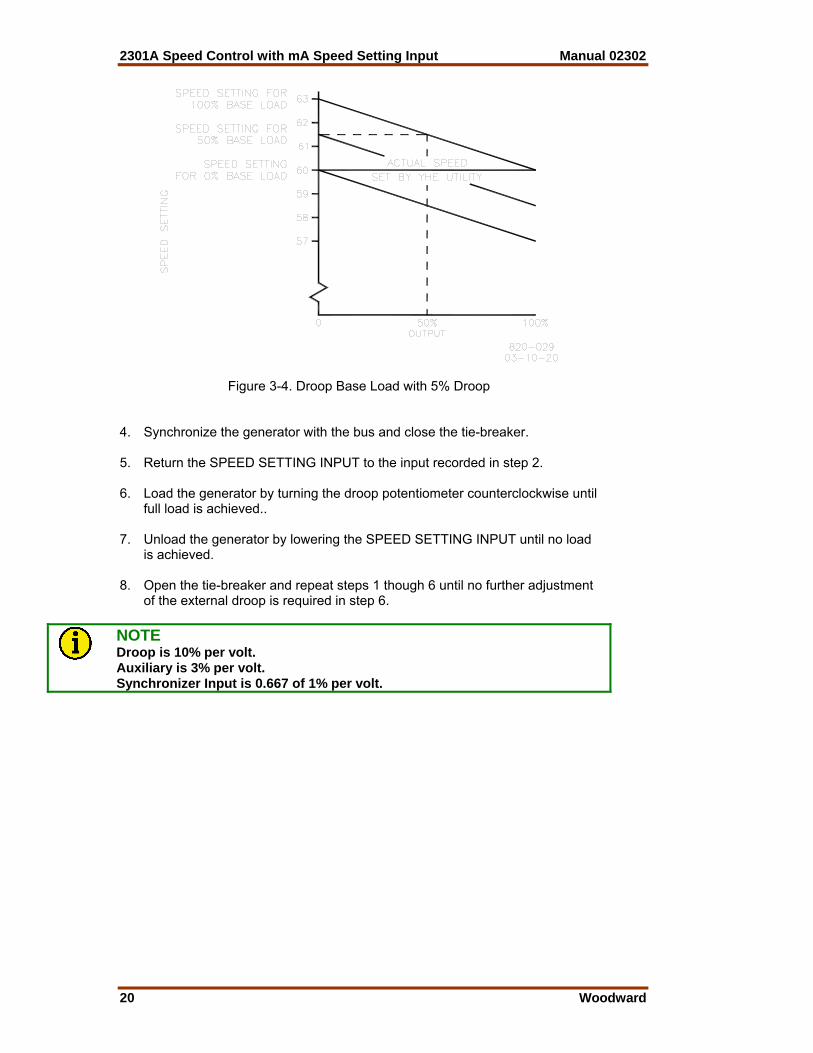
Figure 3-3. Droop Adjustment To set a specified amount of droop on an infinite bus load: 1. With the generator not paralleled, adjust the SPEED SETTING INPUT
SIGNAL to give a speed setting above 60 Hz by the percent of droop required.
Example: Droop of 5 percent would require raising the speed to 63 Hz. 2. Record the speed setting input, then adjust the SPEED SETTING INPUT for
60 Hz. 3. Turn the external droop potentiometer full CW for maximum droop.
2301A Speed Control with mA Speed Setting Input Manual 02302
20 Woodward
Figure 3-4. Droop Base Load with 5% Droop 4. Synchronize the generator with the bus and close the tie-breaker. 5. Return the SPEED SETTING INPUT to the input recorded in step 2. 6. Load the generator by turning the droop potentiometer counterclockwise until
full load is achieved.. 7. Unload the generator by lowering the SPEED SETTING INPUT until no load
is achieved. 8. Open the tie-breaker and repeat steps 1 though 6 until no further adjustment
of the external droop is required in step 6.
NOTE Droop is 10% per volt. Auxiliary is 3% per volt. Synchronizer Input is 0.667 of 1% per volt.
Manual 02302 2301A Speed Control with mA Speed Setting Input
Woodward 21
Chapter 4. Description of Operation
Introduction The 2301A Speed Control monitors prime-mover speed and maintains it at the operating level determined by the speed setting input or by the low or high limit setting. With the addition of a load sensor the system will share the load with other generators when two or more systems are running in parallel.
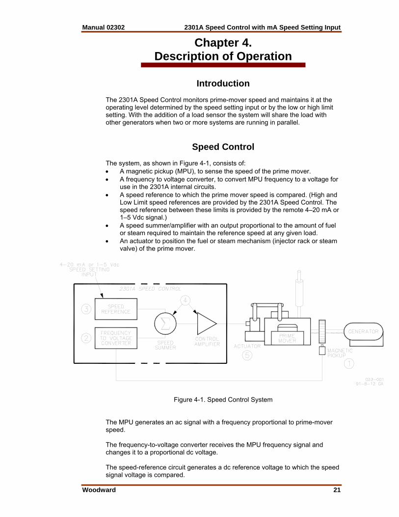
Speed Control The system, as shown in Figure 4-1, consists of: • A magnetic pickup (MPU), to sense the speed of the prime mover. • A frequency to voltage converter, to convert MPU frequency to a voltage for
use in the 2301A internal circuits. • A speed reference to which the prime mover speed is compared. (High and
Low Limit speed references are provided by the 2301A Speed Control. The speed reference between these limits is provided by the remote 4–20 mA or 1–5 Vdc signal.)
• A speed summer/amplifier with an output proportional to the amount of fuel or steam required to maintain the reference speed at any given load.
• An actuator to position the fuel or steam mechanism (injector rack or steam valve) of the prime mover.
Figure 4-1. Speed Control System
The MPU generates an ac signal with a frequency proportional to prime-mover speed. The frequency-to-voltage converter receives the MPU frequency signal and changes it to a proportional dc voltage. The speed-reference circuit generates a dc reference voltage to which the speed signal voltage is compared.

2301A Speed Control with mA Speed Setting Input Manual 02302
22 Woodward
The speed-signal voltage is compared to the reference voltage at the summing point. If the speed-signal voltage is lower or higher than the reference voltage, a signal is sent by the control amplifier calling for an increase or decrease in speed. The actuator is controlled by this signal, repositioning the fuel valve or rack until the speed-signal voltage and the reference voltage are equal.
Auxiliary Inputs Terminals 11 through 17 are used for auxiliary inputs which change the reference voltage and thus the output of the speed control. These inputs include the speed- setting signal, droop, SPM synchronizer, and the auxiliary input, (usually from a load sensor and parallel lines). Failed Speed Signal Circuit A failed-speed-signal circuit monitors the speed-signal input from the MPU. When no signal is detected, it calls for minimum fuel. The minimum-fuel signal is sufficient to cause the actuator to go to the minimum position. Incorrect linkage adjustments or other restrictions in the external system may prevent prime-mover shutdown. For controls with actuator current of 20 to 160 mA, minimum fuel is defined as: • Actuator current of less than 10 mA for forward-acting controls. • Actuator current greater than 180 mA for reverse-acting controls. For controls with actuator current of 4 to 20 mA, minimum fuel is defined as: • Actuator current of less than 2 mA for forward acting controls. • Actuator current of more than 36 mA for reverse-acting controls. A contact to override the failed-speed-signal circuit can be connected in series with terminal 4 and low voltage dc power. (This power is available on terminal 2 for units supplied with 10 to 40 Vdc power and from terminal 6 on those units supplied with about 120 Vac or dc power.) Closing the contact overrides the failed-speed-signal circuit as required for start-up. The control must be tuned to each system for optimum performance. The potentiometers for setting and adjusting these circuits are located in the upper right corner of the control as shown in Figure 4-2. They include: • The RATED SPEED/LOW LIMIT potentiometer, adjusted so the converter-
speed voltage and the reference-speed voltage are equal at the desired minimum operating speed. This may be set as high as rated speed, if desired, limiting the ability of the process or computer speed setting to reduce speed. If needed, the low-limit setting can be used to control engine operation on loss of the speed-reference signal.
• The HIGH LIMIT potentiometer, sets the maximum speed reference that can
be demanded by the control signal. This prevents control signals in excess of normal from causing overspeed.
Manual 02302 2301A Speed Control with mA Speed Setting Input
Woodward 23
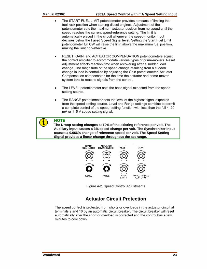
• The START FUEL LIMIT potentiometer provides a means of limiting the fuel-rack position when starting diesel engines. Adjustment of the potentiometer sets the maximum actuator position from no speed until the speed reaches the current speed-reference setting. The limit is automatically placed in the circuit whenever the speed-monitor input declines below the Failed Speed Signal level. Setting the Start Fuel Limit potentiometer full CW will raise the limit above the maximum fuel position, making the limit non-effective.
• RESET, GAIN, and ACTUATOR COMPENSATION potentiometers adjust
the control amplifier to accommodate various types of prime-movers. Reset adjustment affects reaction time when recovering after a sudden load change. The magnitude of the speed change resulting from a sudden change in load is controlled by adjusting the Gain potentiometer. Actuator Compensation compensates for the time the actuator and prime-mover system take to react to signals from the control.
• The LEVEL potentiometer sets the base signal expected from the speed
setting source. • The RANGE potentiometer sets the level of the highest signal expected
from the speed setting source. Level and Range settings combine to permit a complete control of the speed-setting function with less than the full 4–20 mA or 1–5 V speed setting signal.
NOTE The Droop setting changes at 10% of the existing reference per volt. The Auxiliary input causes a 3% speed change per volt. The Synchronizer input causes a 0.666% change of reference speed per volt. The Speed Setting Signal provides a linear change throughout the set range.
Figure 4-2. Speed Control Adjustments
Actuator Circuit Protection The speed control is protected from shorts or overloads in the actuator circuit at terminals 9 and 10 by an automatic circuit breaker. The circuit breaker will reset automatically after the short or overload is corrected and the control has a few minutes to cool down.
2301A Speed Control with mA Speed Setting Input Manual 02302
24 Woodward
Reverse Acting Controls The reverse-acting 2301A Full Authority Speed Control and its actuator are designed so that zero voltage to the actuator corresponds to maximum fuel to the prime mover. The actuator usually used with a reverse-acting control has a mechanical governing mechanism included. The speed setting of this mechanical governor is slightly higher than the speed setting of the 2301A. Should the electronics fail, the actuator will try to go to maximum fuel but will be stopped when it gets to the speed setting of the mechanical governor, providing continued operation of the prime mover, although at a speed which is slightly higher than the electronic control speed reference.
Manual 02302 2301A Speed Control with mA Speed Setting Input
Woodward 25
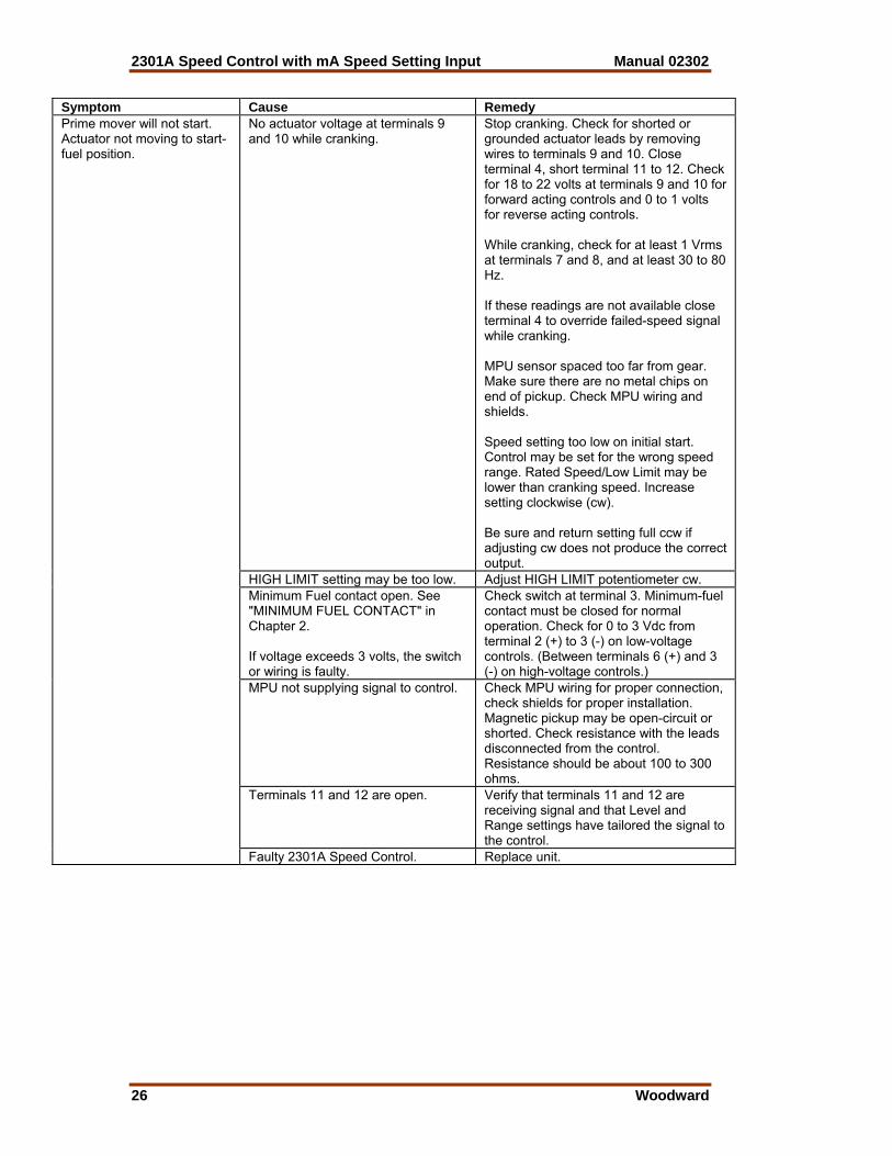
Chapter 5. Troubleshooting
The following troubleshooting guide is an aid in isolating trouble to the control box, actuator, plant wiring, or elsewhere. The guide assumes that the system wiring, soldering connections, switch and relay contacts, and input and output connections are correct and in good working order. Make the checks in the order indicated.
NOTE The wrong voltage can damage the control. When replacing a control, check the power supply, battery, etc., for the correct voltage as indicated on the name tag on the control. Both high-voltage and low-voltage models of 2301A speed controls are available. The low-voltage model will be damaged if connected to a high-voltage supply. The high-voltage model will not operate with a low-voltage supply.
Symptom Cause Remedy DC supply voltage polarity reversed, no supply voltage, or supply voltage is low.
Check for supply voltage within limits indicated on control name tag. Reverse leads if dc polarity is incorrect.
Actuator not responding to input signal from control. NOTE: Hydraulic actuators must have oil pressure and either gear rotation or oil motor rotation to operate.
If there is a voltage output at terminals 9 and 10, but the actuator does not move, the wiring to the actuator should be checked for opens or shorts. With the EG3P actuator, remember that terminals C and D of the mating plug must be jumpered. Coil resistance in a Woodward actuator with terminals 9 and 10 disconnected, is about 35 ohms. Turn start fuel limit cw until prime mover starts.
Prime mover will not start. Actuator not moving to start-fuel position.
Start fuel limit set too low.
Check actuator and linkage for proper installation and operation. Problems may be oil supply, direction of rotation, insufficient drainage, linkage, worn actuator components, or improper adjustment.
2301A Speed Control with mA Speed Setting Input Manual 02302
26 Woodward
Symptom Cause Remedy
No actuator voltage at terminals 9 and 10 while cranking.
Stop cranking. Check for shorted or grounded actuator leads by removing wires to terminals 9 and 10. Close terminal 4, short terminal 11 to 12. Check for 18 to 22 volts at terminals 9 and 10 for forward acting controls and 0 to 1 volts for reverse acting controls. While cranking, check for at least 1 Vrms at terminals 7 and 8, and at least 30 to 80 Hz. If these readings are not available close terminal 4 to override failed-speed signal while cranking. MPU sensor spaced too far from gear. Make sure there are no metal chips on end of pickup. Check MPU wiring and shields. Speed setting too low on initial start. Control may be set for the wrong speed range. Rated Speed/Low Limit may be lower than cranking speed. Increase setting clockwise (cw). Be sure and return setting full ccw if adjusting cw does not produce the correct output.
HIGH LIMIT setting may be too low. Adjust HIGH LIMIT potentiometer cw. Minimum Fuel contact open. See "MINIMUM FUEL CONTACT" in Chapter 2. If voltage exceeds 3 volts, the switch or wiring is faulty.
Check switch at terminal 3. Minimum-fuel contact must be closed for normal operation. Check for 0 to 3 Vdc from terminal 2 (+) to 3 (-) on low-voltage controls. (Between terminals 6 (+) and 3 (-) on high-voltage controls.)
MPU not supplying signal to control. Check MPU wiring for proper connection, check shields for proper installation. Magnetic pickup may be open-circuit or shorted. Check resistance with the leads disconnected from the control. Resistance should be about 100 to 300 ohms.
Terminals 11 and 12 are open. Verify that terminals 11 and 12 are receiving signal and that Level and Range settings have tailored the signal to the control.
Prime mover will not start. Actuator not moving to start-fuel position.
Faulty 2301A Speed Control. Replace unit.
Manual 02302 2301A Speed Control with mA Speed Setting Input
Woodward 27
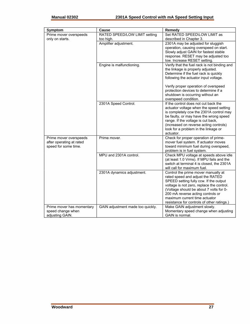
Symptom Cause Remedy
RATED SPEED/LOW LIMIT setting too high.
Set RATED SPEED\LOW LIMIT as described in Chapter 3.
Amplifier adjustment. 2301A may be adjusted for sluggish operation, causing overspeed on start. Slowly adjust GAIN for fastest stable response. RESET may be adjusted too low. Increase RESET setting.
Engine is malfunctioning. Verify that the fuel rack is not binding and the linkage is properly adjusted. Determine if the fuel rack is quickly following the actuator input voltage. Verify proper operation of overspeed protection devices to determine if a shutdown is occurring without an overspeed condition.
Prime mover overspeeds only on starts.
2301A Speed Control. If the control does not cut back the actuator voltage when the speed setting is completely ccw the 2301A control may be faulty, or may have the wrong speed range. If the voltage is cut back, (increased on reverse acting controls) look for a problem in the linkage or actuator.
Prime mover. Check for proper operation of prime-mover fuel system. If actuator moves toward minimum fuel during overspeed, problem is in fuel system.
MPU and 2301A control. Check MPU voltage at speeds above idle (at least 1.0 Vrms). If MPU fails and the switch at terminal 4 is closed, the 2301A will call for maximum fuel.
Prime mover overspeeds after operating at rated speed for some time.
2301A dynamics adjustment. Control the prime mover manually at rated speed and adjust the RATED SPEED setting fully ccw. If the output voltage is not zero, replace the control. (Voltage should be about 7 volts for 0-200 mA reverse acting controls or maximum current time actuator resistance for controls of other ratings.)
Prime mover has momentary speed change when adjusting GAIN.
GAIN adjustment made too quickly. Make GAIN adjustment slowly. Momentary speed change when adjusting GAIN is normal.
2301A Speed Control with mA Speed Setting Input Manual 02302
28 Woodward
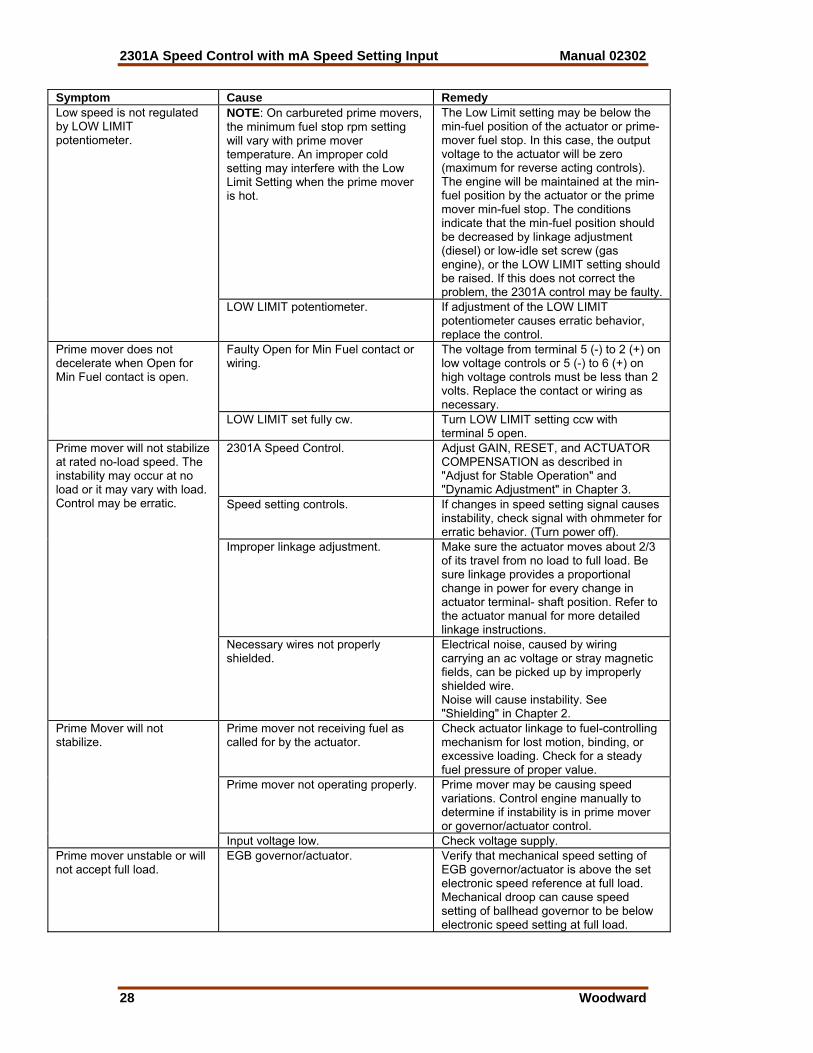
Symptom Cause Remedy
NOTE: On carbureted prime movers, the minimum fuel stop rpm setting will vary with prime mover temperature. An improper cold setting may interfere with the Low Limit Setting when the prime mover is hot.
The Low Limit setting may be below the min-fuel position of the actuator or prime-mover fuel stop. In this case, the output voltage to the actuator will be zero (maximum for reverse acting controls). The engine will be maintained at the min-fuel position by the actuator or the prime mover min-fuel stop. The conditions indicate that the min-fuel position should be decreased by linkage adjustment (diesel) or low-idle set screw (gas engine), or the LOW LIMIT setting should be raised. If this does not correct the problem, the 2301A control may be faulty.
Low speed is not regulated by LOW LIMIT potentiometer.
LOW LIMIT potentiometer. If adjustment of the LOW LIMIT potentiometer causes erratic behavior, replace the control.
Faulty Open for Min Fuel contact or wiring.
The voltage from terminal 5 (-) to 2 (+) on low voltage controls or 5 (-) to 6 (+) on high voltage controls must be less than 2 volts. Replace the contact or wiring as necessary.
Prime mover does not decelerate when Open for Min Fuel contact is open.
LOW LIMIT set fully cw. Turn LOW LIMIT setting ccw with terminal 5 open.
2301A Speed Control. Adjust GAIN, RESET, and ACTUATOR COMPENSATION as described in "Adjust for Stable Operation" and "Dynamic Adjustment" in Chapter 3.
Speed setting controls. If changes in speed setting signal causes instability, check signal with ohmmeter for erratic behavior. (Turn power off).
Improper linkage adjustment. Make sure the actuator moves about 2/3 of its travel from no load to full load. Be sure linkage provides a proportional change in power for every change in actuator terminal- shaft position. Refer to the actuator manual for more detailed linkage instructions.
Prime mover will not stabilize at rated no-load speed. The instability may occur at no load or it may vary with load. Control may be erratic.
Necessary wires not properly shielded.
Electrical noise, caused by wiring carrying an ac voltage or stray magnetic fields, can be picked up by improperly shielded wire. Noise will cause instability. See "Shielding" in Chapter 2.
Prime mover not receiving fuel as called for by the actuator.
Check actuator linkage to fuel-controlling mechanism for lost motion, binding, or excessive loading. Check for a steady fuel pressure of proper value.
Prime mover not operating properly. Prime mover may be causing speed variations. Control engine manually to determine if instability is in prime mover or governor/actuator control.
Prime Mover will not stabilize.
Input voltage low. Check voltage supply. Prime mover unstable or will not accept full load.
EGB governor/actuator. Verify that mechanical speed setting of EGB governor/actuator is above the set electronic speed reference at full load. Mechanical droop can cause speed setting of ballhead governor to be below electronic speed setting at full load.

Manual 02302 2301A Speed Control with mA Speed Setting Input
Woodward 29
Chapter 6. Service Options
Product Service Options The following factory options are available for servicing Woodward equipment, based on the standard Woodward Product and Service Warranty (5-01-1205) that is in effect at the time the product is purchased from Woodward or the service is performed: • Replacement/Exchange (24-hour service) • Flat Rate Repair • Flat Rate Remanufacture If you are experiencing problems with installation or unsatisfactory performance of an installed system, the following options are available: • Consult the troubleshooting guide in the manual. • Contact Woodward technical assistance (see “How to Contact Woodward”
later in this chapter) and discuss your problem. In most cases, your problem can be resolved over the phone. If not, you can select which course of action you wish to pursue based on the available services listed in this section.
Replacement/Exchange Replacement/Exchange is a premium program designed for the user who is in need of immediate service. It allows you to request and receive a like-new replacement unit in minimum time (usually within 24 hours of the request), providing a suitable unit is available at the time of the request, thereby minimizing costly downtime. This is also a flat rate structured program and includes the full standard Woodward product warranty (Woodward Product and Service Warranty 5-01-1205). This option allows you to call in the event of an unexpected outage, or in advance of a scheduled outage, to request a replacement control unit. If the unit is available at the time of the call, it can usually be shipped out within 24 hours. You replace your field control unit with the like-new replacement and return the field unit to the Woodward facility as explained below (see “Returning Equipment for Repair” later in this chapter). Charges for the Replacement/Exchange service are based on a flat rate plus shipping expenses. You are invoiced the flat rate replacement/exchange charge plus a core charge at the time the replacement unit is shipped. If the core (field unit) is returned to Woodward within 60 days, Woodward will issue a credit for the core charge. [The core charge is the average difference between the flat rate replacement/exchange charge and the current list price of a new unit.] Return Shipment Authorization Label. To ensure prompt receipt of the core, and avoid additional charges, the package must be properly marked. A return authorization label is included with every Replacement/Exchange unit that leaves Woodward. The core should be repackaged and the return authorization label affixed to the outside of the package. Without the authorization label, receipt of the returned core could be delayed and cause additional charges to be applied.
2301A Speed Control with mA Speed Setting Input Manual 02302
30 Woodward
Flat Rate Repair Flat Rate Repair is available for the majority of standard products in the field. This program offers you repair service for your products with the advantage of knowing in advance what the cost will be. All repair work carries the standard Woodward service warranty (Woodward Product and Service Warranty 5-01-1205) on replaced parts and labor. Flat Rate Remanufacture Flat Rate Remanufacture is very similar to the Flat Rate Repair option with the exception that the unit will be returned to you in “like-new” condition and carry with it the full standard Woodward product warranty (Woodward Product and Service Warranty 5-01-1205). This option is applicable to mechanical products only.
Returning Equipment for Repair If a control (or any part of an electronic control) is to be returned to Woodward for repair, please contact Woodward in advance to obtain a Return Authorization Number. When shipping the item(s), attach a tag with the following information: • name and location where the control is installed; • name and phone number of contact person; • complete Woodward part number(s) and serial number(s); • description of the problem; • instructions describing the desired type of repair.
CAUTION—ELECTROSTATIC DISCHARGE To prevent damage to electronic components caused by improper handling, read and observe the precautions in Woodward manual 82715, Guide for Handling and Protection of Electronic Controls, Printed Circuit Boards, and Modules. Packing a Control Use the following materials when returning a complete control: • protective caps on any connectors; • antistatic protective bags on all electronic modules; • packing materials that will not damage the surface of the unit; • at least 100 mm (4 inches) of tightly packed, industry-approved packing
material; • a packing carton with double walls; • a strong tape around the outside of the carton for increased strength.
Manual 02302 2301A Speed Control with mA Speed Setting Input
Woodward 31
Return Authorization Number When returning equipment to Woodward, please telephone and ask for the Customer Service Department [1 (800) 523-2831 in North America or +1 (970) 482-5811]. They will help expedite the processing of your order through our distributors or local service facility. To expedite the repair process, contact Woodward in advance to obtain a Return Authorization Number, and arrange for issue of a purchase order for the item(s) to be repaired. No work can be started until a purchase order is received.
NOTE We highly recommend that you make arrangement in advance for return shipments. Contact a Woodward customer service representative at 1 (800) 523-2831 in North America or +1 (970) 482-5811 for instructions and for a Return Authorization Number.
Replacement Parts When ordering replacement parts for controls, include the following information: • the part number(s) (XXXX-XXXX) that is on the enclosure nameplate; • the unit serial number, which is also on the nameplate.
How to Contact Woodward In North America use the following address when shipping or corresponding: Woodward Governor Company PO Box 1519 1000 East Drake Rd Fort Collins CO 80522-1519, USA Telephone—+1 (970) 482-5811 (24 hours a day) Toll-free Phone (in North America)—1 (800) 523-2831 Fax—+1 (970) 498-3058 For assistance outside North America, call one of the following international Woodward facilities to obtain the address and phone number of the facility nearest your location where you will be able to get information and service. Facility Phone Number Brazil +55 (19) 3708 4800 India +91 (129) 230 7111 Japan +81 (476) 93-4661 The Netherlands +31 (23) 5661111 You can also contact the Woodward Customer Service Department or consult our worldwide directory on Woodward’s website (www.woodward.com) for the name of your nearest Woodward distributor or service facility.

2301A Speed Control with mA Speed Setting Input Manual 02302
32 Woodward
Engineering Services Woodward Industrial Controls Engineering Services offers the following after-sales support for Woodward products. For these services, you can contact us by telephone, by email, or through the Woodward website. • Technical Support • Product Training • Field Service Contact information: Telephone—+1 (970) 482-5811 Toll-free Phone (in North America)—1 (800) 523-2831 Email—[email protected] Website—www.woodward.com Technical Support is available through our many worldwide locations or our authorized distributors, depending upon the product. This service can assist you with technical questions or problem solving during normal business hours. Emergency assistance is also available during non-business hours by phoning our toll-free number and stating the urgency of your problem. For technical support, please contact us via telephone, email us, or use our website and reference Customer Services and then Technical Support. Product Training is available at many of our worldwide locations (standard classes). We also offer customized classes, which can be tailored to your needs and can be held at one of our locations or at your site. This training, conducted by experienced personnel, will assure that you will be able to maintain system reliability and availability. For information concerning training, please contact us via telephone, email us, or use our website and reference Customer Services and then Product Training. Field Service engineering on-site support is available, depending on the product and location, from one of our many worldwide locations or from one of our authorized distributors. The field engineers are experienced both on Woodward products as well as on much of the non-Woodward equipment with which our products interface. For field service engineering assistance, please contact us via telephone, email us, or use our website and reference Customer Services and then Technical Support.

Manual 02302 2301A Speed Control with mA Speed Setting Input
Woodward 33
Technical Assistance If you need to telephone for technical assistance, you will need to provide the following information. Please write it down here before phoning: General Your Name Site Location Phone Number Fax Number Prime Mover Information Engine/Turbine Model Number Manufacturer Number of Cylinders (if applicable) Type of Fuel (gas, gaseous, steam, etc) Rating Application Control/Governor Information Please list all Woodward governors, actuators, and electronic controls in your system: Woodward Part Number and Revision Letter Control Description or Governor Type Serial Number Woodward Part Number and Revision Letter Control Description or Governor Type Serial Number Woodward Part Number and Revision Letter Control Description or Governor Type Serial Number If you have an electronic or programmable control, please have the adjustment setting positions or the menu settings written down and with you at the time of the call.

We appreciate your comments about the content of our publications.
Send comments to: [email protected]
Please include the manual number from the front cover of this publication.
PO Box 1519, Fort Collins CO 80522-1519, USA 1000 East Drake Road, Fort Collins CO 80525, USA Phone +1 (970) 482-5811 • Fax +1 (970) 498-3058
Email and Website—www.woodward.com
Woodward has company-owned plants, subsidiaries, and branches, as well as authorized distributors and other authorized service and sales facilities throughout the world.
Complete address / phone / fax / email information for all locations is available on our website.
06/5/F