2.4 and 2.5 meter nomadic antennas - cpi i · 2.4 and 2.5 meter nomadic antennas ... • 2.4m with...
TRANSCRIPT
NO
MA
DIC
MIL
SAT
PBESA24_25MNMD.E1
All designs, specifications, and availabilities of products and services presented in this bulletin are subject to change without notice. (0118A)
© 2018 CPI Antenna Systems Division
2.4 and 2.5 Meter Nomadic Antennas
• MultipleVersionsavailable• 2.4mwithone-,three-,andnine-piecereflectorpanels• 2.5mwithone-piecereflectorpanel• Motorizedandnon-motorizedaxes• Pedestal,TacticalandMobileMounts• Eight-caseISOshippableversion• Lightweightreflector,highaccuracytrackingmount• Interchangeablefeedsystemsforquickfieldswaps• MeetsallapplicableFCC,ITUandMil-Specstandards• DesignedtocomplywithMIL-STD-810F• Varioustrailerconfigurationsareavailable• LowPIMX-bandavailable
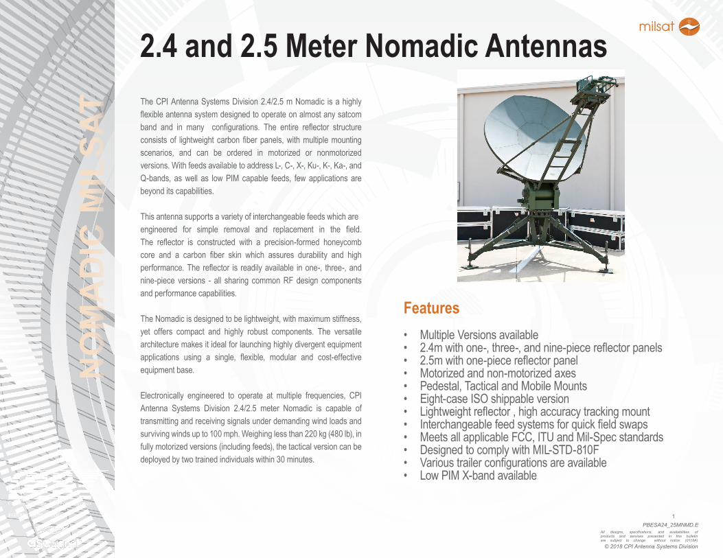
TheCPIAntennaSystemsDivision2.4/2.5mNomadic isahighlyflexibleantennasystemdesignedtooperateonalmostanysatcomband and in many configurations. The entire reflector structureconsistsof lightweight carbonfiberpanels,withmultiplemountingscenarios, and can be ordered in motorized or nonmotorizedversions.WithfeedsavailabletoaddressL-,C-,X-,Ku-,K-,Ka-,andQ-bands, aswell as lowPIM capable feeds, few applications arebeyonditscapabilities.
Thisantennasupportsavarietyofinterchangeablefeedswhichareengineered for simple removal and replacement in the field.The reflector is constructed with a precision-formed honeycombcore and a carbon fiber skin which assures durability and highperformance.The reflector is readilyavailable inone-, three-,andnine-piece versions - all sharing commonRFdesign componentsandperformancecapabilities.
TheNomadicisdesignedtobelightweight,withmaximumstiffness,yet offers compact and highly robust components. The versatilearchitecturemakesitidealforlaunchinghighlydivergentequipmentapplications using a single, flexible, modular and cost-effectiveequipmentbase.
Electronically engineered to operate at multiple frequencies, CPIAntenna Systems Division 2.4/2.5 meter Nomadic is capable oftransmittingandreceivingsignalsunderdemandingwindloadsandsurvivingwindsupto100mph.Weighinglessthan220kg(480lb),infullymotorizedversions(includingfeeds),thetacticalversioncanbedeployedbytwotrainedindividualswithin30minutes.
Features
NO
MA
DIC
MIL
SAT
PBESA24_25MNMD.E2
All designs, specifications, and availabilities of products and services presented in this bulletin are subject to change without notice. (0118A)
© 2018 CPI Antenna Systems Division
2.4 and 2.5 Meter Nomadic Antennas
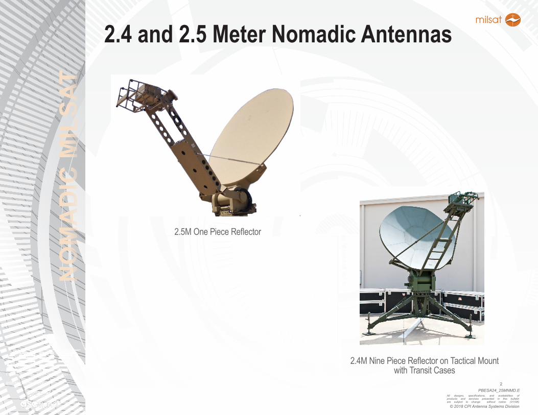
2.5MOnePieceReflector
2.4MNinePieceReflectoronTacticalMountwithTransitCases
NO
MA
DIC
MIL
SAT
PBESA24_25MNMD.E3
All designs, specifications, and availabilities of products and services presented in this bulletin are subject to change without notice. (0118A)
© 2018 CPI Antenna Systems Division
2.4 and 2.5 Meter Nomadic Antennas
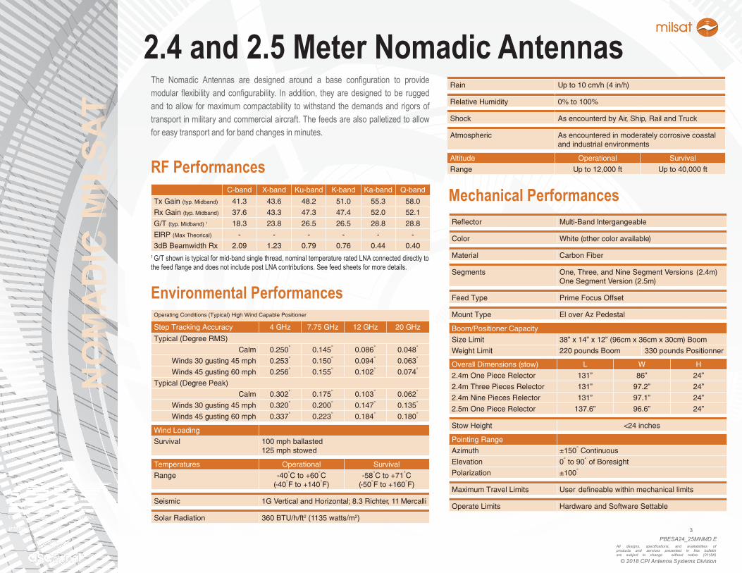
RF PerformancesC-band X-band Ku-band K-band Ka-band Q-band
Tx Gain (typ. Midband) 41.3 43.6 48.2 51.0 55.3 58.0
Rx Gain (typ. Midband) 37.6 43.3 47.3 47.4 52.0 52.1
G/T (typ. Midband) 1 18.3 23.8 26.5 26.5 28.8 28.8
EIRP (Max Theorical) - - - - - -
3dB Beamwidth Rx 2.09 1.23 0.79 0.76 0.44 0.40
The Nomadic Antennas are designed around a base configuration to providemodularflexibilityandconfigurability. Inaddition, theyaredesigned tobe ruggedand toallow formaximumcompactability towithstand thedemandsandrigorsoftransportinmilitaryandcommercialaircraft.Thefeedsarealsopalletizedtoallowforeasytransportandforbandchangesinminutes.
1G/Tshownistypicalformid-bandsinglethread,nominaltemperatureratedLNAconnecteddirectlytothefeedflangeanddoesnotincludepostLNAcontributions.Seefeedsheetsformoredetails.
Environmental PerformancesOperating Conditions (Typical) High Wind Capable Positioner
Step Tracking Accuracy 4 GHz 7.75 GHz 12 GHz 20 GHz
Typical (Degree RMS)
Calm 0.250° 0.145° 0.086° 0.048°
Winds 30 gusting 45 mph 0.253° 0.150° 0.094° 0.063°
Winds 45 gusting 60 mph 0.256° 0.155° 0.102° 0.074°
Typical (Degree Peak)
Calm 0.302° 0.175° 0.103° 0.062°
Winds 30 gusting 45 mph 0.320° 0.200° 0.147° 0.135°
Winds 45 gusting 60 mph 0.337° 0.223° 0.184° 0.180°
Wind Loading
Survival 100 mph ballasted125 mph stowed
Temperatures Operational Survival
Range -40°C to +60°C(-40°F to +140°F)
-58°C to +71°C(-50°F to +160°F)
Seismic 1G Vertical and Horizontal; 8.3 Richter, 11 Mercalli
Solar Radiation 360 BTU/h/ft2 (1135 watts/m2)
Rain Up to 10 cm/h (4 in/h)
Relative Humidity 0% to 100%
Shock As encounterd by Air, Ship, Rail and Truck
Atmospheric As encountered in moderately corrosive coastal and industrial environments
Altitude Operational Survival
Range Up to 12,000 ft Up to 40,000 ft
Mechanical PerformancesReflector Multi-Band Intergangeable
Color White (other color available)
Material Carbon Fiber
Segments One, Three, and Nine Segment Versions (2.4m)One Segment Version (2.5m)
Feed Type Prime Focus Offset
Mount Type El over Az Pedestal
Boom/Positioner Capacity
Size Limit 38” x 14” x 12” (96cm x 36cm x 30cm) Boom
Weight Limit 220 pounds Boom 330 pounds Positionner
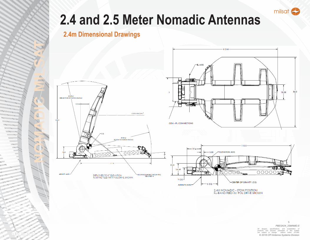
Overall Dimensions (stow) L W H
2.4m One Piece Relector 131” 86” 24”
2.4m Three Pieces Relector 131” 97.2” 24”
2.4m Nine Pieces Relector 131” 97.1” 24”
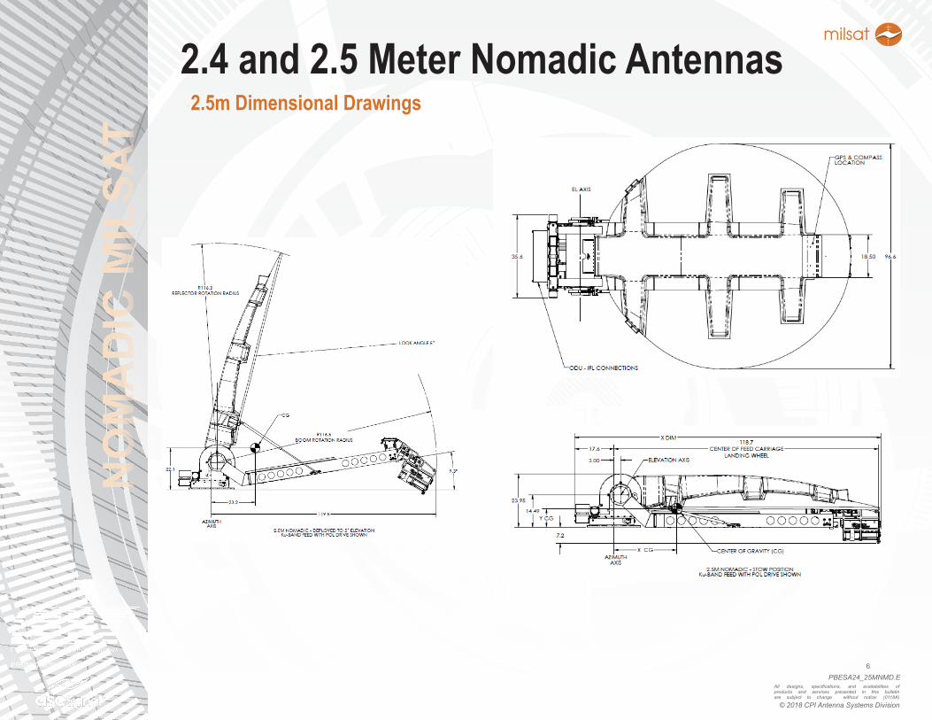
2.5m One Piece Relector 137.6” 96.6” 24”
Stow Height <24 inches
Pointing Range
Azimuth ±150° Continuous
Elevation 0° to 90° of Boresight
Polarization ±100°
Maximum Travel Limits User defineable within mechanical limits
Operate Limits Hardware and Software Settable
NO
MA
DIC
MIL
SAT
PBESA24_25MNMD.E4
All designs, specifications, and availabilities of products and services presented in this bulletin are subject to change without notice. (0118A)
© 2018 CPI Antenna Systems Division
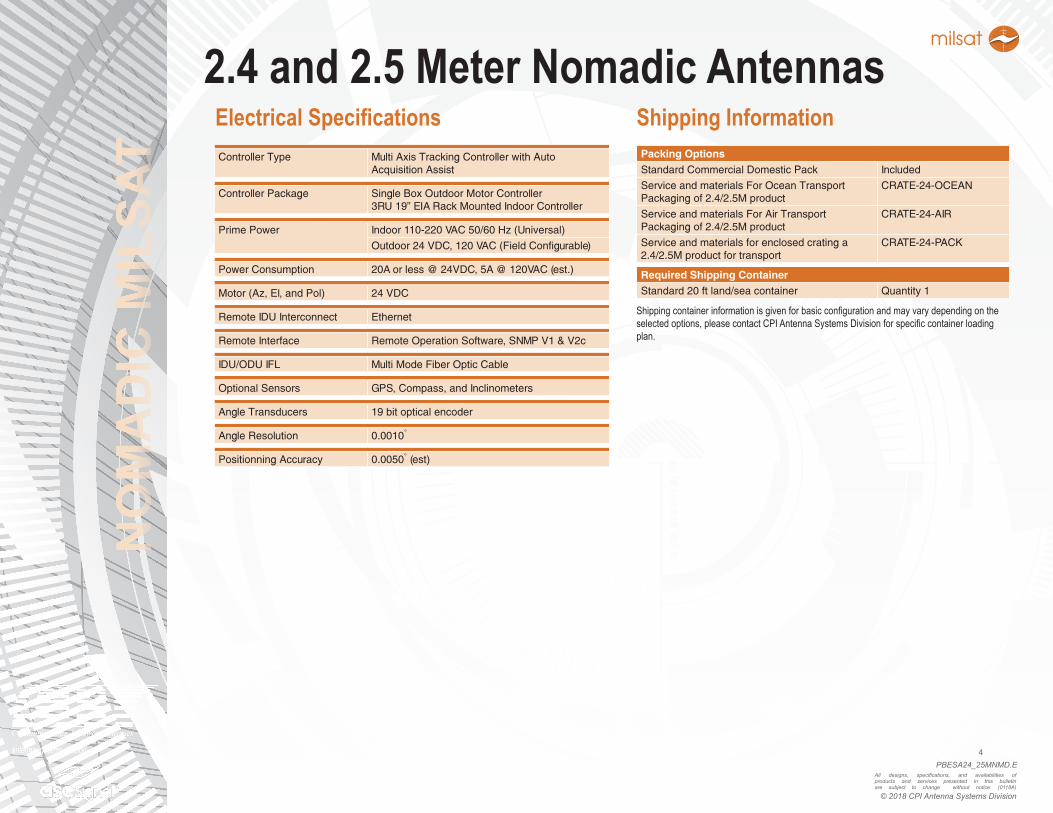
2.4 and 2.5 Meter Nomadic AntennasElectrical SpecificationsController Type Multi Axis Tracking Controller with Auto
Acquisition Assist
Controller Package Single Box Outdoor Motor Controller3RU 19” EIA Rack Mounted Indoor Controller
Prime Power Indoor 110-220 VAC 50/60 Hz (Universal)
Outdoor 24 VDC, 120 VAC (Field Configurable)
Power Consumption 20A or less @ 24VDC, 5A @ 120VAC (est.)
Motor (Az, El, and Pol) 24 VDC
Remote IDU Interconnect Ethernet
Remote Interface Remote Operation Software, SNMP V1 & V2c
IDU/ODU IFL Multi Mode Fiber Optic Cable
Optional Sensors GPS, Compass, and Inclinometers
Angle Transducers 19 bit optical encoder
Angle Resolution 0.0010°
Positionning Accuracy 0.0050° (est)
Packing OptionsStandard Commercial Domestic Pack Included
Service and materials For Ocean Transport Packaging of 2.4/2.5M product
CRATE-24-OCEAN
Service and materials For Air Transport Packaging of 2.4/2.5M product
CRATE-24-AIR
Service and materials for enclosed crating a 2.4/2.5M product for transport
CRATE-24-PACK
Required Shipping ContainerStandard 20 ft land/sea container Quantity 1
Shipping Information
Shippingcontainerinformationisgivenforbasicconfigurationandmayvarydependingontheselectedoptions,pleasecontactCPIAntennaSystemsDivisionforspecificcontainerloadingplan.
NO
MA
DIC
MIL
SAT
PBESA24_25MNMD.E5
All designs, specifications, and availabilities of products and services presented in this bulletin are subject to change without notice. (0118A)
© 2018 CPI Antenna Systems Division
2.4 and 2.5 Meter Nomadic Antennas2.4m Dimensional Drawings
NO
MA
DIC
MIL
SAT
PBESA24_25MNMD.E6
All designs, specifications, and availabilities of products and services presented in this bulletin are subject to change without notice. (0118A)
© 2018 CPI Antenna Systems Division
2.4 and 2.5 Meter Nomadic Antennas2.5m Dimensional Drawings
NO
MA
DIC
MIL
SAT
PBESA24_25MNMD.E7
All designs, specifications, and availabilities of products and services presented in this bulletin are subject to change without notice. (0118A)
© 2018 CPI Antenna Systems Division
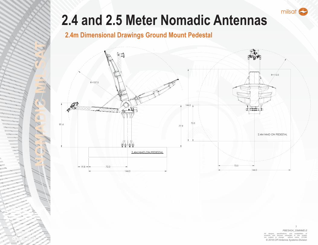
2.4 and 2.5 Meter Nomadic Antennas2.4m Dimensional Drawings Ground Mount Pedestal
72.019.8
144.0
2.4M NMD ON PEDESTAL
77.981.6
R=107.5
72.0
72.0
144.0
144.0
2.4M NMD ON PEDESTAL
R=112.0
NO
MA
DIC
MIL
SAT
PBESA24_25MNMD.E8
All designs, specifications, and availabilities of products and services presented in this bulletin are subject to change without notice. (0118A)
© 2018 CPI Antenna Systems Division
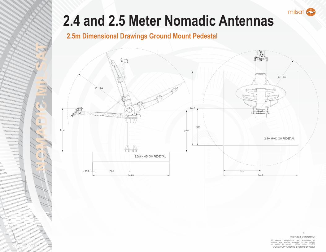
2.4 and 2.5 Meter Nomadic Antennas2.5m Dimensional Drawings Ground Mount Pedestal
72.0
81.6
19.8
144.0
77.9
R=116.5
2.5M NMD ON PEDESTAL
72.0
72.0
144.0
144.0
R=112.0
2.5M NMD ON PEDESTAL
NO
MA
DIC
MIL
SAT
PBESA24_25MNMD.E9
All designs, specifications, and availabilities of products and services presented in this bulletin are subject to change without notice. (0118A)
© 2018 CPI Antenna Systems Division
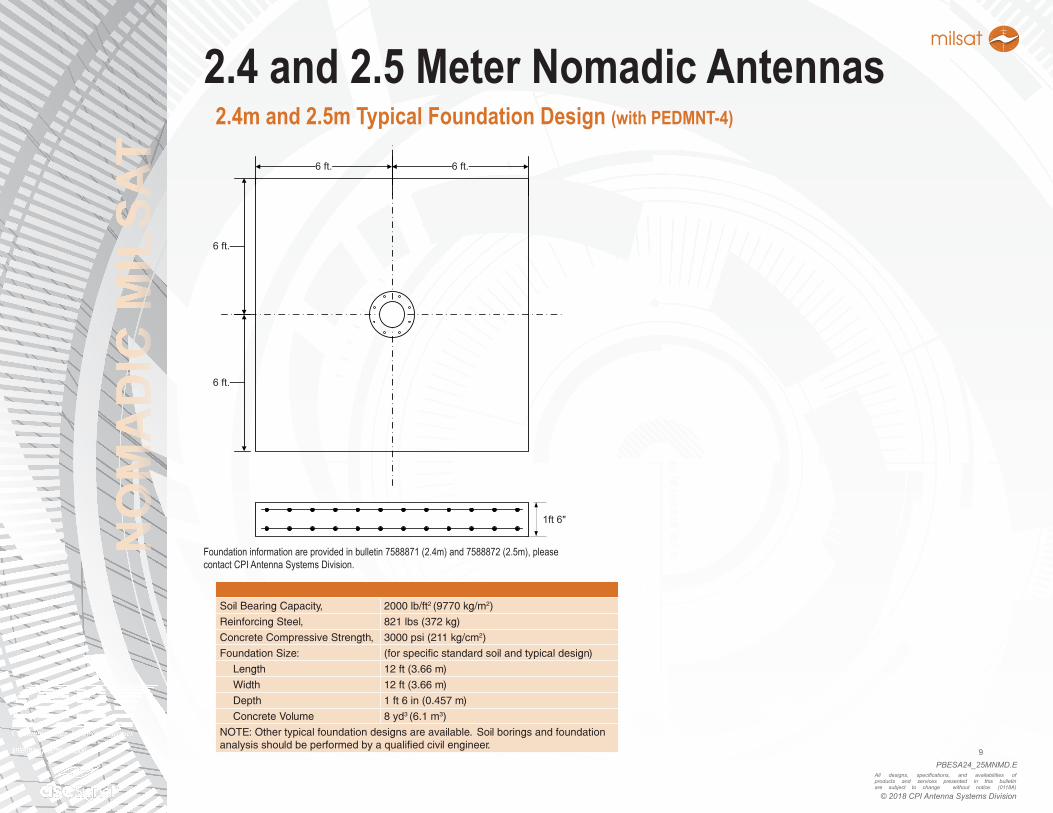
2.4 and 2.5 Meter Nomadic Antennas2.4m and 2.5m Typical Foundation Design (with PEDMNT-4)
Soil Bearing Capacity, 2000 lb/ft2 (9770 kg/m2)
Reinforcing Steel, 821 lbs (372 kg)
Concrete Compressive Strength, 3000 psi (211 kg/cm2)
Foundation Size: (for specific standard soil and typical design)
Length 12 ft (3.66 m)
Width 12 ft (3.66 m)
Depth 1 ft 6 in (0.457 m)
Concrete Volume 8 yd3 (6.1 m3)
NOTE: Other typical foundation designs are available. Soil borings and foundation analysis should be performed by a qualified civil engineer.
Foundationinformationareprovidedinbulletin7588871(2.4m)and7588872(2.5m),pleasecontactCPIAntennaSystemsDivision.
6 ft. 6 ft.
6 ft.
6 ft.
1ft 6"
NO
MA
DIC
MIL
SAT
PBESA24_25MNMD.E10
All designs, specifications, and availabilities of products and services presented in this bulletin are subject to change without notice. (0118A)
© 2018 CPI Antenna Systems Division
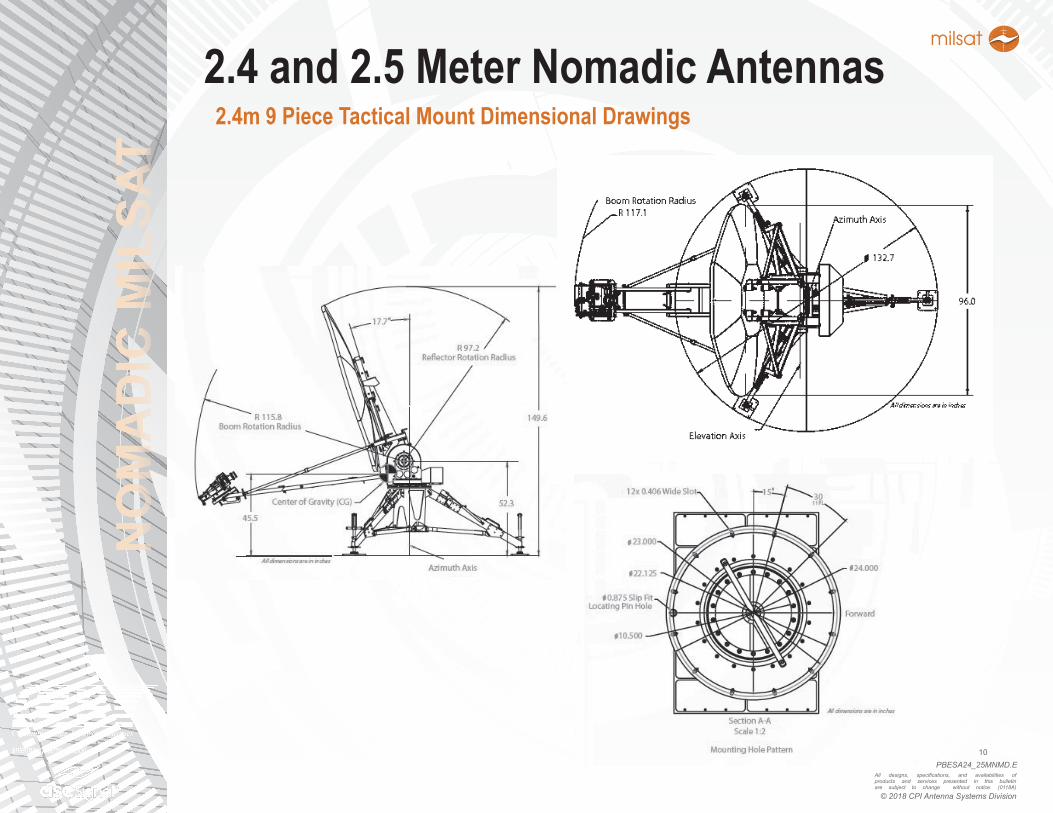
2.4 and 2.5 Meter Nomadic Antennas2.4m 9 Piece Tactical Mount Dimensional Drawings
NO
MA
DIC
MIL
SAT
PBESA24_25MNMD.E11
All designs, specifications, and availabilities of products and services presented in this bulletin are subject to change without notice. (0118A)
© 2018 CPI Antenna Systems Division
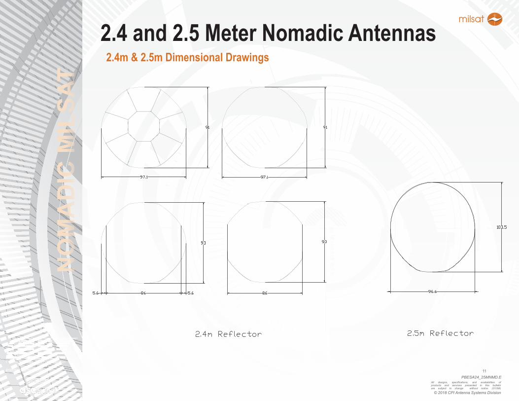
2.4 and 2.5 Meter Nomadic Antennas2.4m & 2.5m Dimensional Drawings
NO
MA
DIC
MIL
SAT
PBESA24_25MNMD.E12
All designs, specifications, and availabilities of products and services presented in this bulletin are subject to change without notice. (0118A)
© 2018 CPI Antenna Systems Division
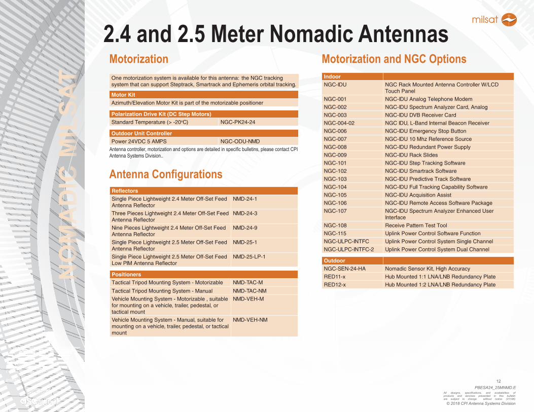
2.4 and 2.5 Meter Nomadic AntennasOne motorization system is available for this antenna: the NGC tracking system that can support Steptrack, Smartrack and Ephemeris orbital tracking.
Motor KitAzimuth/Elevation Motor Kit is part of the motorizable positioner
Polarization Drive Kit (DC Step Motors)Standard Temperature (> -20oC) NGC-PK24-24
Outdoor Unit ControllerPower 24VDC 5 AMPS NGC-ODU-NMD
Motorization
ReflectorsSingle Piece Lightweight 2.4 Meter Off-Set Feed Antenna Reflector
NMD-24-1
Three Pieces Lightweight 2.4 Meter Off-Set Feed Antenna Reflector
NMD-24-3
Nine Pieces Lightweight 2.4 Meter Off-Set Feed Antenna Reflector
NMD-24-9
Single Piece Lightweight 2.5 Meter Off-Set Feed Antenna Reflector
NMD-25-1
Single Piece Lightweight 2.5 Meter Off-Set Feed Low PIM Antenna Reflector
NMD-25-LP-1
PositionersTactical Tripod Mounting System - Motorizable NMD-TAC-M
Tactical Tripod Mounting System - Manual NMD-TAC-NM
Vehicle Mounting System - Motorizable , suitable for mounting on a vehicle, trailer, pedestal, or tactical mount
NMD-VEH-M
Vehicle Mounting System - Manual, suitable for mounting on a vehicle, trailer, pedestal, or tactical mount
NMD-VEH-NM
Antenna Configurations
Antennacontroller,motorizationandoptionsaredetailedinspecificbulletins,pleasecontactCPIAntennaSystemsDivision..
Motorization and NGC OptionsIndoorNGC-IDU NGC Rack Mounted Antenna Controller W/LCD
Touch Panel
NGC-001 NGC-IDU Analog Telephone Modem
NGC-002 NGC-IDU Spectrum Analyzer Card, Analog
NGC-003 NGC-IDU DVB Receiver Card
NGC-004-02 NGC IDU, L-Band Internal Beacon Receiver
NGC-006 NGC-IDU Emergency Stop Button
NGC-007 NGC-IDU 10 Mhz Reference Source
NGC-008 NGC-IDU Redundant Power Supply
NGC-009 NGC-IDU Rack Slides
NGC-101 NGC-IDU Step Tracking Software
NGC-102 NGC-IDU Smartrack Software
NGC-103 NGC-IDU Predictive Track Software
NGC-104 NGC-IDU Full Tracking Capability Software
NGC-105 NGC-IDU Acquisition Assist
NGC-106 NGC-IDU Remote Access Software Package
NGC-107 NGC-IDU Spectrum Analyzer Enhanced User Interface
NGC-108 Receive Pattern Test Tool
NGC-115 Uplink Power Control Software Function
NGC-ULPC-INTFC Uplink Power Control System Single Channel
NGC-ULPC-INTFC-2 Uplink Power Control System Dual Channel
OutdoorNGC-SEN-24-HA Nomadic Sensor Kit, High Accuracy
RED11-x Hub Mounted 1:1 LNA/LNB Redundancy Plate
RED12-x Hub Mounted 1:2 LNA/LNB Redundancy Plate
NO
MA
DIC
MIL
SAT
PBESA24_25MNMD.E13
All designs, specifications, and availabilities of products and services presented in this bulletin are subject to change without notice. (0118A)
© 2018 CPI Antenna Systems Division
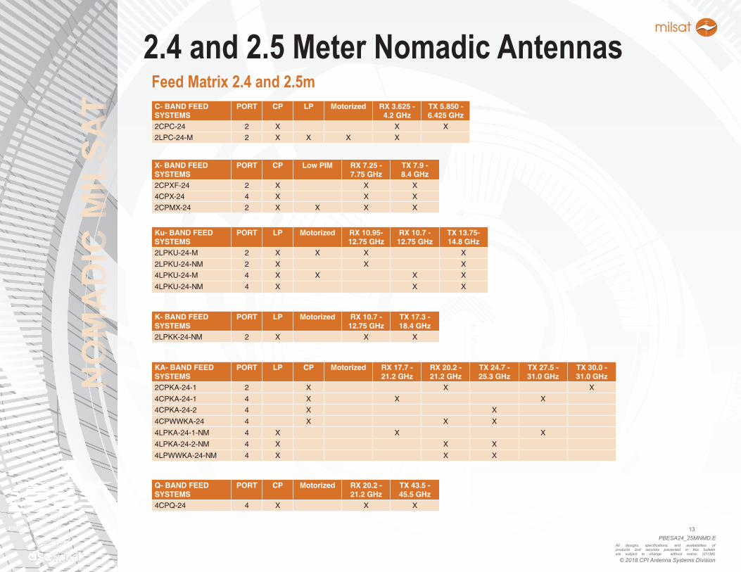
2.4 and 2.5 Meter Nomadic AntennasC- BAND FEED SYSTEMS
PORT CP LP Motorized RX 3.625 - 4.2 GHz
TX 5.850 - 6.425 GHz
2CPC-24 2 X X X
2LPC-24-M 2 X X X X
X- BAND FEED SYSTEMS
PORT CP Low PIM RX 7.25 - 7.75 GHz
TX 7.9 - 8.4 GHz
2CPXF-24 2 X X X
4CPX-24 4 X X X
2CPMX-24 2 X X X X
Feed Matrix 2.4 and 2.5m
K- BAND FEED SYSTEMS
PORT LP Motorized RX 10.7 - 12.75 GHz
TX 17.3 - 18.4 GHz
2LPKK-24-NM 2 X X X
Ku- BAND FEED SYSTEMS
PORT LP Motorized RX 10.95- 12.75 GHz
RX 10.7 - 12.75 GHz
TX 13.75-14.8 GHz
2LPKU-24-M 2 X X X X
2LPKU-24-NM 2 X X X
4LPKU-24-M 4 X X X X
4LPKU-24-NM 4 X X X
KA- BAND FEED SYSTEMS
PORT LP CP Motorized RX 17.7 - 21.2 GHz
RX 20.2 - 21.2 GHz
TX 24.7 - 25.3 GHz
TX 27.5 - 31.0 GHz
TX 30.0 - 31.0 GHz
2CPKA-24-1 2 X X X
4CPKA-24-1 4 X X X
4CPKA-24-2 4 X X
4CPWWKA-24 4 X X X
4LPKA-24-1-NM 4 X X X
4LPKA-24-2-NM 4 X X X
4LPWWKA-24-NM 4 X X X
Q- BAND FEED SYSTEMS
PORT CP Motorized RX 20.2 - 21.2 GHz
TX 43.5 - 45.5 GHz
4CPQ-24 4 X X X
NO
MA
DIC
MIL
SAT
PBESA24_25MNMD.E14
All designs, specifications, and availabilities of products and services presented in this bulletin are subject to change without notice. (0118A)
© 2018 CPI Antenna Systems Division
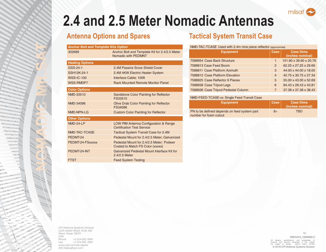
2.4 and 2.5 Meter Nomadic AntennasAnchor Bolt and Template Kits Option
302689 Anchor Bolt and Template Kit for 2.4/2.5 Meter Nomadic with PEDMNT
Heating Options
GSS-24-1 2.4M Passive Snow Shield Cover
SSH12K-24-1 2.4M 4KW Electric Heater System
WSS-IC-100 Interface Cable; 100ft
WSS-RMDP7 Rack Mounted Remote Monitor Panel
Color Options
NMD-33510 Sandstone Color Painting for Reflector FS33510
NMD-34096 Olive Drab Color Painting for Reflector FS34096
NMD-NPN-LG Custom Color Painting for Reflector
Other Options
NMD-24-LP LOW PIM Antenna Configuration & Range Certification Test Service
NMD-TAC-TCASE Tactical System Transit Case for 2.4M
PEDMT-24 Pedestal Mount for 2.4/2.5 Meter; Galvanized
PEDMT-24-FSxxxxx Pedestal Mount for 2.4/2.5 Meter; Podwer Coated to Match FS Color (xxxxx)
PEDMT-24-INT Galvanized Pedestal Mount Interface Kit for 2.4/2.5 Meter
FTST Feed System Testing
Antenna Options and Spares
CPI Antenna Systems Division1120 Jupiter Road, Suite 102Plano Texas 75074USAPhone: +1-214-291-7654Fax: +1-214-291-7655www.cpii.com/[email protected]
NMD-TAC-TCASE Used with 2.4m nine piece reflector (approximate)
Equipment Case Case Dims(inches nominal)
7588954 Case Back Structure 1 101.80 x 39.90 x 20.79
7588813 Case Feed Boom 2 62.25 x 27.25 x 29.69
7588811 Case Platform Azimuth 3 44.00 x 44.00 x 18.00
7588812 Case Platform Elevation 4 42.75 x 30.75 x 27.34
7588925 Case Reflector 9 Pieces 5 55.00 x 43.00 x 52.69
7588938 Case Tripod Legs 6 84.43 x 28.43 x 43.81
7588936 Case Tripod Pedestal Column 7 37.38 x 37.38 x 38.43
Tactical System Transit Case
NMD-FEED-TCASE-xx Single Feed Transit Case
Equipment Case Case Dims(inches nominal)
PN to be defined depends on feed system part number for foam cutout
8+ TBD