2.4 ghz photonic antenna for wireless local area …
TRANSCRIPT

56 Recent Developments in Small Size Antenna
5
2.4 GHz PHOTONIC ANTENNA FOR WIRELESS LOCAL AREA NETWORK
Razali Ngah Teguh Prakoso
Tharek Abd Rahman Goh Kean Chuan
5.1 INTRODUCTION Photonic antenna can be defined as intimate integration of optoelectronics with planar antenna to produce a highly multifunction module. Some works have been done to integrate optoelectronics with antenna. Among them, some focus on downlink side (photodiode integration with antenna) and some concentrate on uplink side (integration of laser diode with antenna). There are also some publications on bidirectional photonic antenna, which cover uplink and downlink. The bidirectional photonic antenna can be categorized into two groups, i.e. which use optoelectronics transceiver such as asymmetric Fabry-Perot modulator (AFPM) and separate photodetector and laser. AFPM is very specialized device, rarely available in the market, and its transceiver nature limit the flexibility of performance optimization for uplink and downlink. On other side, vertical cavity surface emitting laser (VCSEL) and photodiode can be easily found in the market, lower cost, allowing independent optimization for uplink and downlink, and reliable. To the best of author’s knowledge, all publications on photonic antenna are measurement-based. This chapter uses simulation software to evaluate photonic antenna performance, to

2.4 GHz Photonic Antenna for Wireless Local Area Network 57
allow flexibility in design optimization, cost and time effective design process, and more complete evaluation parameter due to the use of optical communication system simulation. This chapter presents a 2.4 GHz photonic antenna design, simulation, and performance evaluation of photonic antenna using optical communication system software.
5.2 2.4 GHz PHOTONIC ANTENNA DESIGN FOR WLAN Design of the photonic antenna is described in Figure 5.1. Optoelectronics (VCSEL and photodiode) is integrated with microstrip patch antenna. The rectangular microstrip antenna is designed to operate at 2.4 GHz, allowing to be used for IEEE 802.11 b/g communication. The method of optoelectronics integration with antenna is as follows. Firstly, the optoelectronics is characterized to ensure it can function properly in the optical link. The important parameters are port impedance (S11) and bandwidth (S21) of the optoelectronics. With the knowledge of S11, impedance matching with antenna can be designed. The S11 of optoelectronics can be measured using network analyzer. The second requirement is the optoelectronics bandwidth, which is measured using network analyzer and wideband optical fiber and laser (for photodiode being characterized) or wideband optical fiber and photodiode (for laser being characterized). After S11 and S21 are obtained, link budget can be calculated and suitability of the optoelectronics can be evaluated. The result of optoelectronics characterization is depicted in Figure 5.2 (VCSEL) and Figure 5.3 (photodiode).

58 Recent Developments in Small Size Antenna
Figure 5.1 Photonic antenna showing a VCSEL bonded to a
microstrip carrier and mounted on a rectangular microstrip antenna: (a) side view, (b) top view
(a)
(b)
Figure 5.2 Characteristic of VCSEL as result of measurement: (a) return loss, (b) normalized modulation bandwidth

2.4 GHz Photonic Antenna for Wireless Local Area Network 59
(a)
(b) Figure 5.3 Characteristic of photodiode as result of measurement: (a) smith chart of input impedance, (b) bandwidth
Secondly, the suitable optoelectronics are then mounted in the antenna and measured as photonic antenna. The mounting arrangement is shown in Figure 5.1. Uplink and downlink photonic antenna can be measured separately to determine its total link gain or loss. The measurement can take place in anechoic chamber. From these measurements, bidirectional link budget can be calculated, and any potential problem (such as unbalanced link budget between uplink and downlink) can be identified and necessary improvement can be determined and implemented. Measurement result for downlink and uplink photonic antenna is depicted in Figure 5.4.

60 Recent Developments in
Small Size Antenna
(a) (b) Figure 5.1 Measured normalized frequency response of the photonic antennas: (a) downlink, (b) uplink
Figure 5.2 Diagram showing bidirectional communication using photonic antenna

2.4 GHz Photonic Antenna for Wireless Local Area Network 61
Finally, the uplink and downlink photonic antennas are used as part of bidirectional communication link. Peer-to-peer communication between two WLAN enabled laptop, as shown in Figure 5.5, can be used as simple test to the system. The system in the figure is successful to transfer data across the link at data rate 370 kbps, fiber length from 50-500 m, and wireless distance of 5-10 cm.
5.3 DESIGN AND SIMULATION This section presents design and simulation of photonic antenna for WLAN at 2.4 GHz. The 2.4 GHz microstrip antenna is designed using procedure in Balanis and then simulated using Agilent Advanced Design System (ADS) to evaluate its return loss and gain. Then, the antenna is included in the optical communication system simulation using Optisystem, with 64QAM modulation.
5.3.1 Antenna Design
The geometry of a square patch antenna is shown in Figure 5.6. The Patch has a dimension of L x W and is printed on a substrate that has a thickness of 1.6 mm with a loss tangent of 0.019. The L and W are 26 mm and 41.5 mm, respectively. The antenna is fed by 50 Ohm transmission line-feed to the radiating patch. The transmission line geometry is also calculated as L*W which are 2.882 mm and 14.37 mm, respectively. After calculating all required parameters needed for designing an antenna, ADS is used for simulation. The first step is to draw the antenna geometry and dimension, as shown in Figure 5.6. ADS uses grid in drawing, making the dimension of the antenna to be simulated must be adjusted to the grid. The dimension of the

62 Recent Developments in Small Size Antenna
transmission line used in the simulation is 2.88 mm by 15 mm, the value of W is 41.91 mm and the L is 25.9 mm, slightly different from the values calculated previously. The feed line e is extended to 23.5mm. Theoretically, the longer the feed line e the higher loss on antenna, because of the higher impedances.
Figure 5.3 The designed patch antenna
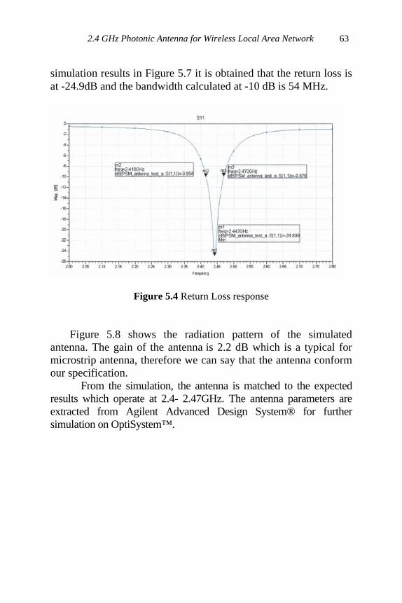
5.3.2 Antenna Simulation Results The antenna is designed to have the highest return loss at 2.442 GHz. The patch antenna dimension of 41.45 mm (W) and 26 mm (L) as shown in Figure 5.6 is first try out with the transmission feed line in the middle. However, the return loss is not meet the specification value (< - 10 dB). By moving the feed line towards the center of the patch, it gradually increases the return loss up to -24.9 dB which is much better than in the middle. From the
2.4 GHz Photonic Antenna for Wireless Local Area Network 63
simulation results in Figure 5.7 it is obtained that the return loss is at -24.9dB and the bandwidth calculated at -10 dB is 54 MHz.
Figure 5.4 Return Loss response
Figure 5.8 shows the radiation pattern of the simulated antenna. The gain of the antenna is 2.2 dB which is a typical for microstrip antenna, therefore we can say that the antenna conform our specification. From the simulation, the antenna is matched to the expected results which operate at 2.4- 2.47GHz. The antenna parameters are extracted from Agilent Advanced Design System® for further simulation on OptiSystem™.

64 Recent Developments in Small Size Antenna
Figure 5.5 Radiation Patterns
5.3.3 Optical System Design
The photonic antenna is considered to be used to transmit wireless local area network (WLAN) signal. The center frequency of the antenna is 2.44 GHz (WLAN channel number 6). The bit rate is up to 54 Mbps and the modulation scheme is 64QAM. This is to be able for the testing process on the designed antenna.
2.4 GHz Photonic Antenna for Wireless Local Area Network 65
5.3.3.1 64 QAM Radio Signal Generation
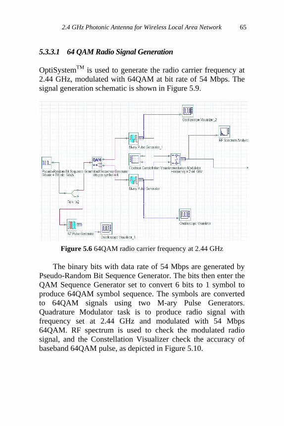
OptiSystemTM is used to generate the radio carrier frequency at 2.44 GHz, modulated with 64QAM at bit rate of 54 Mbps. The signal generation schematic is shown in Figure 5.9.
Figure 5.6 64QAM radio carrier frequency at 2.44 GHz
The binary bits with data rate of 54 Mbps are generated by Pseudo-Random Bit Sequence Generator. The bits then enter the QAM Sequence Generator set to convert 6 bits to 1 symbol to produce 64QAM symbol sequence. The symbols are converted to 64QAM signals using two M-ary Pulse Generators. Quadrature Modulator task is to produce radio signal with frequency set at 2.44 GHz and modulated with 54 Mbps 64QAM. RF spectrum is used to check the modulated radio signal, and the Constellation Visualizer check the accuracy of baseband 64QAM pulse, as depicted in Figure 5.10.

66 Recent Developments in Small Size Antenna
(a) (b)
Figure 5.7 (a) Constellation of signals I symbol carried 6 bits. (b) The output signals of the 64QAM modulator
5.3.3.2 Simulation of Radio over Fiber System The radio signal modulates optical signal using intensity modulation – direct detection (IMDD) technique. This scheme is chosen due to its simplicity and practicality. To provide better link gain and to avoid laser chirp, external optical modulation using Mach-Zehnder Modulator (MZM) is implemented. The modulator needs CW Laser as light source. Modulated optical signal is then launched to single mode optical fiber (SMF). This optical signal generation is described in left part of Figure 5.11. Photonic Antenna consists of a photodetector PIN, an electrical band pass filter, and a micro-strip patch antenna. The photodetector PIN convert back the RF signal from modulated light and pass to the band pass filter (BPF) to filter out the unwanted signals. Then the microstrip antenna radiates the RF signal to the receiver. The photonic antenna is depicted in the right hand side of Figure 5.11.

2.4 GHz Photonic Antenna for Wireless Local Area Network 67
Figure 5.8 Radio over fiber schematic, including the photonic antenna (downlink)
The simulation results are shown at Figure 5.12. Part (a) shows RF modulated optical signal at MZM output, centered at 1550 nm (the same as CW Laser wavelength). Part (b) is RF signal converted from received modulated optical signal by PIN photodetector. The signal is centered at 2.44 GHz, and contains many additional sidebands due to optical link nonlinearity. BPF can filter out the sidebands, as described by part (c) in the figure. Finally, part (d) is reflected signal by the microstrip antenna that has around 10 dB below the incoming signal, showing that the antenna radiates 90% of incoming power. This value is common specification for antenna, i.e. maximum reflected signal is 10%. In this simulation, the microstrip antenna is represented by S1P Block, which contains S11 parameter of the antenna. By referring the results, the antenna works well on 2.44 GHz radio frequency.

68 Recent Developments in Small Size Antenna
(a) (b)
(c) (d)
Figure 5.9 Radio over fiber signal: (a) modulated optical output, (b) received RF signal at photodetector PIN, (c) received signal after filter, (d) reflected signal from the antenna 5.3.4 Bidirectional Photonic Antenna
Reflected signal from the microstrip antenna can be used to

2.4 GHz Photonic Antenna for Wireless Local Area Network 69
the uplink are the same with downlink, as described in the previous section.
Figure 5.10 Design of photonic antenna with downlink and uplink signal
Photonic antenna has been simulated with the signals transmit from base center to end user (downlink) and end user to base center (uplink). The photonic antenna application in WLAN gives several advantages such as simple circuits design, small size and low cost.

70 Recent Developments in Small Size Antenna
5.3.5 Design of Photonic Antenna with APD Photodiode
The photonic antenna now replaces the PIN photodetector with APD photodiode, since the APD has higher responsivity than PIN photodiode. As expected, power generated at APS output is higher compared to PIN photodiode as described in previous section. The received spectrums are depicted in Figure 5.14. The results show that APD photodiode can be used to increase the power radiated by the photonic antenna in downlink.
(a) (b)
Figure 5.11 Received signals (APD) (a) before and (b) after filtered 5.3.6 Final Design of Photonic Antenna
The photonic antenna which includes photo-detector, optical modulator, micro-strip patch antenna and BPF. The design of photonic antenna is depend on the requirement on performance and cost budget. Figure 5.15 shows the, final design of the photonic antenna.

2.4 GHz Photonic Antenna for Wireless Local Area Network 71
Figure 5.12 Photonic Antenna
PIN photodiode is cheaper than APD photodiode, although the APD photodiode has higher responsivity. Optical modulation can be done by MZM or direct-modulation laser (DML). Mach-Zehnder modulator gives higher performance on modulating RF signals to optical, but it requires higher cost in fabrication.
5.4 CONCLUSION The design and simulation of 2.4 GHz photonic antenna have been presented. The performance of the proposed system such as loss of optical link, modulation accuracy, noise and distortion introduced by the optical link and RF components, filtering effect, and signal reflection by the microstrip antenna are evaluated. The photonic design presented in this chapter is predicted to function well in the implementation. This chapter also shows that improvement to data rate of communication using photonic antenna is possible. The simulation uses bit rate of 54 Mbps, much higher than 370 kbps achieved by

72 Recent Developments in Small Size Antenna
previous research. REFERENCES Balanis, C. A. (2005) Antenna theory analysis and design, (3 edn)
(Hoboken, New Jersey, Wiley Interscience). Cryan, M. J., Dragas, M., Houle, T., Varazza, R., Hill, M., Yu, S.
& Rorison, J. (2004a) A 2.4 ghz wireless-over-fibre transmitter using a photonic active integrated antenna (phaia). Conference on Lasers and Electro-Optics, 2004. (CLEO).
Cryan, M. J., Dragas, M., Kung, J., Jain, V., Fornetti, F., Houle, T., Varrazza, R. & Hill, M. (2006) A 2.4-ghz wireless-over-fiber transceiver using photonic active integrated antennas (phaias). Microwave and Optical Technology Letters, 48(2), 233-237.
Cryan, W., Dragas, M., Kung, J., Jain, V., Houle, T., Varrazza, R. & Hill, M. (2004b) A 2.4ghz wireless-over-fibre transmitter using a vcsel-based photonic active integrated antenna (phaia). 34th European Microwave Conference, 2004.
Khodier, M. M., Christodoulou, C. G., Liao, T. S. & Yu, P. K. L. (2002) Antenna integration with a waveguide photodetector for high capacity wireless communications. Microwave and Optical Technology Letters, 35(3), 179-184.
Li, K. & Izutsu, M. (2004) Photonic antennas for wireless communication system. IEEJ Transactions on Electronics,Information,and Systems, 124(2), 250-256.
Liu, C., Seeds, A., Chadha, J., Stavrinou, P., Parry, G., Whitehead, M., Krysa, A. & Roberts, J. (2003) Bi-directional transmission of broadband 5.2 ghz wireless signals over fibre using a multiple-quantum-well asymmetric fabry-perot modulator/photodetector. Optical Fiber Communications Conference, 2003. OFC 2003.
Liu, C. P., Seeds, A. J., Chadha, J. S., Stavrinou, P. N., Parry, G., Whitehead, M., Krysa, A. & Roberts, J. S. (2002) Design,

2.4 GHz Photonic Antenna for Wireless Local Area Network 73
fabrication and characterisation of normal-incidence 1.56-µm multiple-quantum-well asymmetric fabry-perot modulators for passive picocells. IEICE Transactions on Electronics, E86-C(7), 1281-1289.
Tzeremes, G., Tanner, H., Liao, T. & Christodoulou, C. (2004) Wireless communication with smart photonic antennas using transmission power control. IEEE Antennas and Wireless Propagation Letters, 3(232-235.
Waterhouse, R. B. (2003) Microstrip patch antennas: A designer's guide, (Boston, Kluwer Academic Publishers).
Yu, P. K. L., Liao, T. S., Tzeremes, G. & Christodoulou, C. G. (2005) High power photodiode for antenna applications. 2005 IEEE Workshop on Microelectronics and Electron Devices, 2005. WMED '05.