*24167314* home keypad lock - lowe's install instructions_lever.pdf · yes. lock is installed...

1
If door dimensions do not match, go to www.nexiahome.com for drilling instructions. 2a. Check dimensions. Pin Wrench AA Batteries (4) not included Alternate Faceplate Keypad Interior Baseplate Interior Cover Strike Lever HOME KEYPAD LOCK INSTALLATION INSTRUCTIONS MODEL FE599 2b. Install strike onto door jamb. Actual Size (2) Check edge of door to determine the type of faceplate required. 2c. If Necessary, change latch faceplate. No change necessary. Install latch and strike. 2 Important Information 1 3a. Remove sticker from hands-free post. Install exterior keypad assembly. 3 Feed the cable through the hole as shown below. DO NOT connect the cable at this point. 4a. Feed cable through interior baseplate Install interior baseplate assembly. 4 Tuck wires into open space on baseplate. Be careful not to pinch any wires between cover and baseplate. 5a. Install interior cover. Install interior cover and lever. 5 1. Find User Code A on the yellow sticker. 2. Enter User Code A (four digits) into the keypad. 3. Rotate and then release lever. 6b. Test outside entry. Test locking function: TEST WITH DOOR OPEN! 6 Latch must be flipped so that bevel faces toward door jamb. 2d. Install Latch. FCC STATEMENT This device complies with part 15 of the FCC rules. Operation is subject to the following two conditions: (1) This device may not cause harmful interference, and (2) this device must accept any interference received, including interference that may cause undesired operation. Changes or modifications to this equipment not expressly approved by Schlage could void the user’s authority to operate the equipment. FCC ID: P2GFE599 IC: 7654A-FE599 Jamb Hands-free Post 3b. Install exterior keypad. Bar should slide smoothly through hole in latch. If not, check door dimensions. Exterior IMPORTANT Cable must slide under latch. Bar 3c. Adjust hands-free post. The hands-free post is the threaded stud on back of lock. It’s purpose (in step 4) is to attach the lock and baseplate together so that the lock will hold itself on the door. Hands- free post may need to be adjusted with a screwdriver to the dimensions shown. Latch Latch/Strike Screws (4) Contents © 2012 Ingersoll Rand Printed in U.S.A. 24167314 05/12 a Key Cover Screws (2) Tools Needed • Phillips screwdriver • Tape Measure • Pencil Optional • Flathead Screwdriver • Wood Block • Hammer Do not use a power drill for installation Hands-free post should lock plate against door surface. 4b. Slide baseplate onto door over hands-free post. Snap the connectors together. Route wires so they will not be pinched. 4c. Connect the cable. 4d. Install batteries and battery cover. If the lever does not snap into place easily, you may have to tap the lever with a hammer using a piece of wood to cushion it. Be careful not to damage the finish of the lever. 5b. Install interior lever. No change necessary 5c. If needed, switch levers. *24167314* 24167314 CAUTION If Lock Removal is Required Hands free post must be disengaged to prevent damage to lock. To Unlock (from inside): Press the Unlock button. Green = Unlocked 6a. Test locking and unlocking from the Interior. 2C\,” (60 mm) OR 2C\v” (70 mm) 2Z\,” (53 mm) Hole Bevel Z\," - Z\v" (3mm - 6mm) Adjust with screwdriver so screw extends beyond door edge. Hands-free post Hold keypad against door Interior If hands-free post does not lock plate onto door, see step 3c for adjustment. Hands-free post See step 5c to verify that the lever is handed correctly to match your door. To Change Lever Handing Correct Incorrect 1 2 3 4 Actual Size (2) OR Did latch retract and then extend? Yes. Lock is installed correctly. No. Latch retracted but did not extend (latch bound). Check step 3b. No. Nothing happened. Check steps 4c and 4d. To lock (from Inside): Press the Lock button. Red = Locked Press Press 6c. Connecting your lock to the Iris™ system Adding your lock to an existing Iris™ system: 1. Log into your Iris dashboard and click the ‘devices’ link. 2. Select ‘add devices’ 3. Follow the on screen instructions Adding your lock to a new Iris™ system: 1. Follow the installation guide that was supplied with your Iris™ smart hub. 2. The onscreen installation process will ask which devices you have. Make sure that the doorlock is selected. 3. The onscreen instructions will describe the steps to add your doorlock. Place Label Here Poner la etiqueta aquí Placer l’autocollant ici Default Programming Code Código de programación predeterminado Code du défaut programmation Default User Codes Códigos de usuario predeterminado Codes du défaut utilisateur • Lock comes preset with a default Programming Code. • Lock comes preset with two default User Codes (877) 288-7707 (U.S.A./Canada) nexiahome.com Need Help? OR lowes.com/Iris 1-866-555-IRIS For Iris™ support:

Upload: others

Post on 15-Feb-2020

10 views

Category:

Documents


0 download

TRANSCRIPT

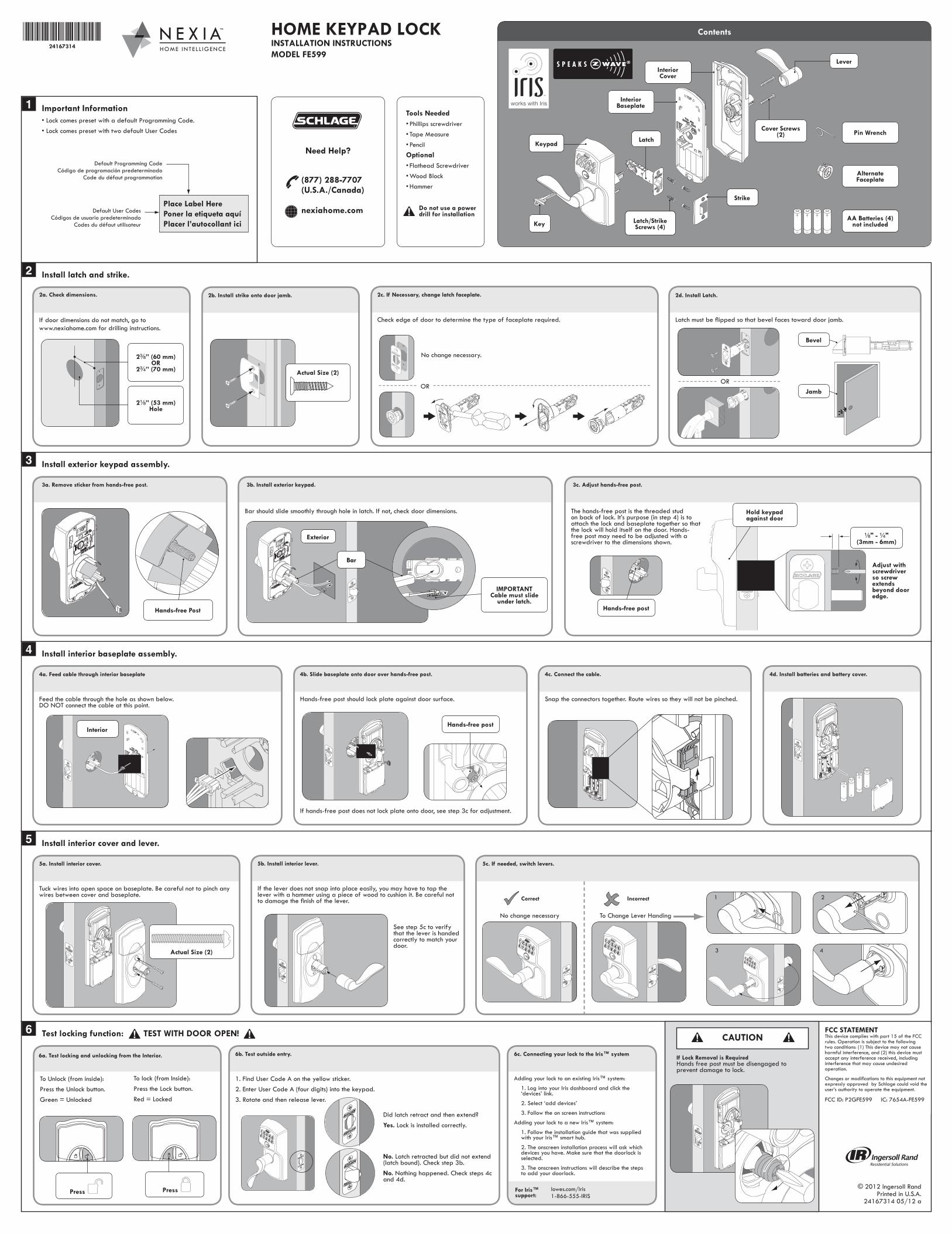
If door dimensions do not match, go towww.nexiahome.com for drilling instructions.

2a. Check dimensions.

Pin Wrench

AA Batteries (4) not included

Alternate Faceplate

Keypad

Interior Baseplate

Interior Cover

Strike

Lever

HOME KEYPAD LOCKINSTALLATION INSTRUCTIONSMODEL FE599

2b. Install strike onto door jamb.

Actual Size (2)

Check edge of door to determine the type of faceplate required.

2c. If Necessary, change latch faceplate.

No change necessary.

Install latch and strike.2

Important Information1

3a. Remove sticker from hands-free post.

Install exterior keypad assembly.3

Feed the cable through the hole as shown below. DO NOT connect the cable at this point.

4a. Feed cable through interior baseplate

Install interior baseplate assembly.4

Tuck wires into open space on baseplate. Be careful not to pinch any wires between cover and baseplate.

5a. Install interior cover.

Install interior cover and lever.5

1. Find User Code A on the yellow sticker.2. Enter User Code A (four digits) into the keypad.3. Rotate and then release lever.

6b. Test outside entry.

Test locking function: TEST WITH DOOR OPEN!6

Latch must be flipped so that bevel faces toward door jamb.

2d. Install Latch.

FCC STATEMENTThis device complies with part 15 of the FCC rules. Operation is subject to the following two conditions: (1) This device may not cause harmful interference, and (2) this device must accept any interference received, including interference that may cause undesired operation.

Changes or modifications to this equipment not expressly approved by Schlage could void the user’s authority to operate the equipment.

FCC ID: P2GFE599 IC: 7654A-FE599

Jamb

Hands-free Post

3b. Install exterior keypad.

Bar should slide smoothly through hole in latch. If not, check door dimensions.

Exterior

IMPORTANTCable must slide

under latch.

Bar

3c. Adjust hands-free post.

The hands-free post is the threaded stud on back of lock. It’s purpose (in step 4) is to attach the lock and baseplate together so that the lock will hold itself on the door. Hands-free post may need to be adjusted with a screwdriver to the dimensions shown.

Latch

Latch/Strike Screws (4)

Contents

© 2012 Ingersoll RandPrinted in U.S.A.

24167314 05/12 a

Key

Cover Screws (2)

Tools Needed• Phillips screwdriver• Tape Measure• PencilOptional• Flathead Screwdriver• Wood Block• Hammer

Do not use a power drill for installation

Hands-free post should lock plate against door surface.

4b. Slide baseplate onto door over hands-free post.

Snap the connectors together. Route wires so they will not be pinched.

4c. Connect the cable. 4d. Install batteries and battery cover.

If the lever does not snap into place easily, you may have to tap the lever with a hammer using a piece of wood to cushion it. Be careful not to damage the finish of the lever.

5b. Install interior lever.

No change necessary

5c. If needed, switch levers.

*24167314*24167314

CAUTION

If Lock Removal is RequiredHands free post must be disengaged to prevent damage to lock.

To Unlock (from inside):Press the Unlock button.Green = Unlocked

6a. Test locking and unlocking from the Interior.

2C\,” (60 mm)OR

2C\v” (70 mm)

2Z\,” (53 mm)Hole

Bevel

Z\," - Z\v"(3mm - 6mm)

Adjust with screwdriver so screw extends beyond door edge.

Hands-free post

Hold keypad against door

Interior

If hands-free post does not lock plate onto door, see step 3c for adjustment.

Hands-free post

See step 5c to verify that the lever is handed correctly to match your door.

To Change Lever Handing

Correct Incorrect 1 2

3 4Actual Size (2)

OR

Did latch retract and then extend?Yes. Lock is installed correctly.

No. Latch retracted but did not extend (latch bound). Check step 3b.No. Nothing happened. Check steps 4c and 4d.

To lock (from Inside):Press the Lock button.Red = Locked

Press Press

6c. Connecting your lock to the Iris™ system

Adding your lock to an existing Iris™ system:

1. Log into your Iris dashboard and click the ‘devices’ link.

2. Select ‘add devices’

3. Follow the on screen instructions

Adding your lock to a new Iris™ system:

1. Follow the installation guide that was supplied with your Iris™ smart hub.

2. The onscreen installation process will ask which devices you have. Make sure that the doorlock is selected.

3. The onscreen instructions will describe the steps to add your doorlock.

Place Label HerePoner la etiqueta aquíPlacer l’autocollant ici

Default Programming CodeCódigo de programación predeterminado

Code du défaut programmation

Default User CodesCódigos de usuario predeterminado

Codes du défaut utilisateur

• Lock comes preset with a default Programming Code.• Lock comes preset with two default User Codes

(877) 288-7707(U.S.A./Canada)

nexiahome.com

Need Help?

OR

lowes.com/Iris 1-866-555-IRIS

For Iris™ support: