26-th ecmi modelling week final report - tu dresden study the heat distribution while neglecting the...
TRANSCRIPT

26-th ECMI Modelling Week
Final Report
19.08.2012—25.08.2012Dresden, Germany
Group 3
Modeling of a storage waterheater
Stefan EberhardDresden University of Technology, Germany
Marina FerreiraUniversity of Coimbra, Portugal
Nicolai S. JohnsenTechnical University of Denmark, Kongens Lyngby, Denmark
Laura S. MendozaUniversity of Strasbourg, France
Igor ZarvanskyNational Technical University of Ukraine, Kiev, Ukraine
Instructor: Joachim KrenciszekKaiserslautern University of Technology, Germany
2

Abstract
Nowadays, hot water is needed on a daily basis. In many households thehot water is provided by a storage water heater. As the water is heated at arelatively slow rate, the question arises how long it takes to heat fresh waterup to a desired temperature when the supply of hot water is running low inthe tank.
The present work documents our attempts to find a model for the heatingprocess as well as an optimal shape for the heating element, such that thetime required to heat up the water is minimized.

2 Modeling of a storage water heater
3.1 Introduction
Hot water has long become indispensable for domestic use, such as cooking,cleaning or personal hygiene. Storage water heaters are appliances providinga sufficiently constant supply of hot water. They consist of a water tankwhich is used for storing the hot water. It is equipped with a heating elementthat often is a closed water circuit, e.g. a pipe. That is due to the highheat capacity of water and the fact that it is also non-toxic and low incost. However, the water is heated at a relatively slow rate, necessitating anoptimization of the shape of the heating element, such that time requiredfor the heating process is minimized.
Because of various assumptions that we have to make, we optimize theheating element in terms of the radius of the pipes versus the number ofloops in the coil. We investigate a case in which the starting temperature ofthe water in the tank is 15C while the desired average temperature at theend of the heating process is 45C. The water inside the heating element isassumed to be 80C constant.
We initially consider the general heat equation describing the diffusion ofthe temperature inside the tank. We solve this equation by discretizing thedomain in order to implement a finite element method in Matlab. We modifythat model by then mimicking the advection, which is the bulk motion ofthe fluid, in accordance with our expectations.
Finally, we draw conclusions on our results and propose possible waysto improve our model.
3.2 The model
Description of the industrial problem we are considering
The water tank in question is of cylindric shape. The heating element isa regularly-shaped coil revolving around a straight tube in its center (cf.Figure 3.1).
Figure 3.1: dimensions of the water tank

26th ECMI modelling week 3
The diameter of the heating pipes is the same for both the coil and itsstraight center piece. We further specify our problem as follows:
• volume of the tank: 200l
• surface area of the heating element : 1m2
• temperature of the heating pipes : 80C
• starting temperature of the water : 15C
• desired average temperature of the water : 45C
Assumptions
For reasons of simplicity we assume that the tank is perfectly insulated whichmeans that the heat can neither leak from the tank nor be absorbed from theoutside. Likewise, we assume that the temperature of the heating elementis not affected by the surrounding water in the tank. As we also neglect thefact that the heating pipes would realistically need time to heat up, we canstate that the temperature of the heating element is 80C constant.
Since computing three-dimensional models is very costly we decided tolimit our model to two dimensions.
We study three different 2D cross sections. In order to keep the resultsas comparable as possible, we assume that the heating system - that is, thecoil and the central straight pipe - goes all the way through the tank. Thiscan be modeled in any of the considered cross sections.
Mathematical setup
To begin with, we only consider the diffusion of heat which means thatwe study the heat distribution while neglecting the bulk motion of the fluid,from now on referred to as advection. This is described by the heat equation
∂u
∂t=
κ
ρc∆u
where :
ρ = 1000kg
m3density
κ = 0.58W
m ·Kthermal conductivity
c = 1000J
kg ·Kspecific heat capacity
One might expect a source term in the heat equation. We neglected that aswe chose to define the heat sources as boundaries. The sources are therefore

4 Modeling of a storage water heater
inner boundaries on which a Dirichlet boundary condition is imposed. Onthe outer boundary we impose a Neumann boundary condition which relatesto the aforementioned perfect insulation of the tank which enables us todisregard potential flux. Additionally, we set the initial condition for allnon-boundary points of the domain Ω ⊆ R2.
• outer boundary Γ1 : Neumann boundary condition
∂u
∂n= 0, x ∈ Γ1
• inner boundary Γ2 : Dirichlet boundary condition
u(x, t) = 80, ∀t ≥ 0, x ∈ Γ2
• initial condition :
u(x, 0) = 15, x ∈ Ω
The different cross sections
The diffusion - and optionally the advection - of heat is considered in threedifferent sections of the tank in order to obtain different viewpoints, hope-fully yielding information on the approximate behaviour of the actual three-dimensional tank. These three sections are (a) the circular cross section,(b) the horizontal rectangular cross section and (c) the vertical rectangularcross section of the tank. See figures 3.2a, 3.2b and 3.2c, respectively.
(a) circular(b) horizontalrectangular (c) vertical rectangular
Figure 3.2: the three sections to be considered
In the circular cross section, the coil is represented by nine circular innerboundaries Γ2 with radius r. (cf. Figure 3.3.) The central circle correspondsto the straight tube in the coil. Although the coil only intersects twice withthe cross section plane, the additional heat from the nearby parts of the coilshould be taken into account. This fact is represented by the 8 surroundingcircles which all impact the heat distribution equally. This only provides acrude estimate and more realistic setups may be derived by accounting for

26th ECMI modelling week 5
a smooth descent of the magnitude of heat from the two circles at whichthe coil in fact intersects to the remaining heat sources. Due to lack oftime, however, we stuck with the initial setup which was also more easilyimplemented in MatLab.
In the rectangular cross sections, the heating element is represented byan inner rectangular boundary and circular boundaries on each side, cor-responding to the straight central tube and the intersections of the coil,respectively. The approach is of a simplified nature yet again as we did notaddress the lack of a bond between the heat sources.
The diffusion in the cross sections 3.2a and 3.2b is modeled in MatLaband solved by applying a finite element method.
In addition to the diffusion of heat, it was suggested by the instructor tomodify the heat flow in order to imitate the behaviour of advection. Thatis, to create an artificial flow of heat allowing hot water to circulate to thetop of the tank and cold water to the bottom of the tank. We realized thisby implementing a MatLab function which rotates the water on predefinedelliptic paths, cf. Figure 3.3b.
In the vertical rectangular cross section (cf. Figure 3.2c) a completelydifferent approach was used. We modeled the problem in Python by solving aconservation equation with a dedicated advection term using a finite volumemethod.
3.3 Numerical analysis and implementation
FEM - a description of the general procedure
In the cross sections 3.2a and 3.2b, we solve the heat equation using theFinite Element Method. Before explaining the procedure, we will statesome important concepts, namely the space L2 and the Hilbert space H1
0 .
Definition 1 Let Ω ⊆ Rn be measurable. We define:
L2(Ω) = f : Ω→ R| f is measurable and
∫Ω
|f(x)|2dx <∞
andH1
0 = u ∈ L2(Ω)|∂xiu ∈ L2(Ω), i = 1, ..., n,where ∂xiu denotes the i-th weak derivative of u.
From the heat equation∂u
∂t=
κ
ρc∆u
we obtain the weak formulation by multiplying by the test functions v ∈H1
0 (Ω) and by integrating by parts∫Ω
∂u
∂tv = − κ
ρc
∫Ω∇u∇v, ∀v ∈ H1
0 (Ω). (3.1)
6 Modeling of a storage water heater
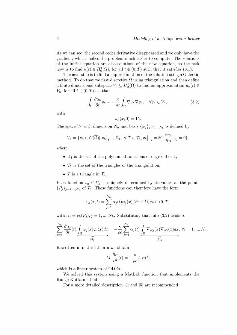
As we can see, the second order derivative disappeared and we only have thegradient, which makes the problem much easier to compute. The solutionsof the initial equation are also solutions of the new equation, so the tasknow is to find u(t) ∈ H1
0 (Ω), for all t ∈ (0, T ) such that it satisfies (3.1).The next step is to find an approximation of the solution using a Galerkin
method. To do that we first discretize Ω using triangulation and then definea finite dimensional subspace Vh ⊆ H1
0 (Ω) to find an approximation uh(t) ∈Vh, for all t ∈ (0, T ), so that∫
Ω
∂uh∂t
vh = − κ
ρc
∫Ω∇uh∇vh, ∀vh ∈ Vh, (3.2)
withuh(x, 0) = 15.
The space Vh with dimension Nh and basis ϕjj=1,...,Nhis defined by
Vh = vh ∈ C(Ω)| vh∣∣T∈ Π1, ∀ T ∈ Th, vh
∣∣Γ2
= 80,∂vh∂n
∣∣Γ1
= 0.
where
• Π1 is the set of the polynomial functions of degree 0 or 1,
• Th is the set of the triangles of the triangulation,
• T is a triangle in Th.
Each function vh ∈ Vh is uniquely determined by its values at the pointsPjj=1,...,Nh
of Th. These functions can therefore have the form
vh(x, t) =
Nh∑j=1
αj(t)ϕj(x),∀x ∈ Ω,∀t ∈ (0, T )
with αj = vh(Pj), j = 1, ..., Nh. Substituting that into (3.2) leads to
Nh∑j=1
∂αj
∂t(t)
∫Ωϕj(x)ϕi(x)dx︸ ︷︷ ︸
Mij
= − κ
ρc
Nh∑j=1
αj(t)
∫Ω∇ϕj(x)∇ϕi(x)dx︸ ︷︷ ︸
Aij
, ∀i = 1, ..., Nh.
Rewritten in matricial form we obtain
M∂α
∂t(t) = − κ
ρcA α(t)
which is a linear system of ODEs.We solved this system using a MatLab function that implements the
Runge-Kutta method.For a more detailed description [3] and [5] are recommended.
26th ECMI modelling week 7
A short description of the programming tools
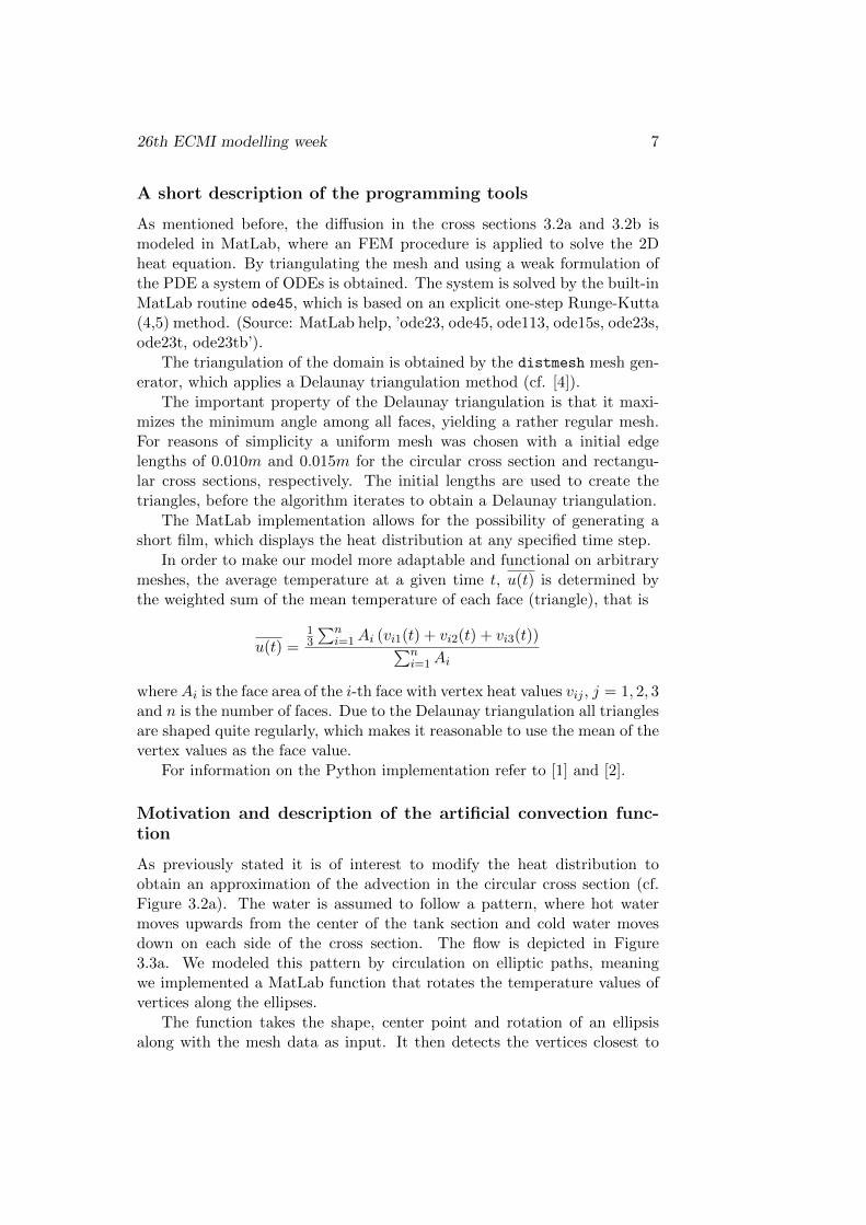
As mentioned before, the diffusion in the cross sections 3.2a and 3.2b ismodeled in MatLab, where an FEM procedure is applied to solve the 2Dheat equation. By triangulating the mesh and using a weak formulation ofthe PDE a system of ODEs is obtained. The system is solved by the built-inMatLab routine ode45, which is based on an explicit one-step Runge-Kutta(4,5) method. (Source: MatLab help, ’ode23, ode45, ode113, ode15s, ode23s,ode23t, ode23tb’).
The triangulation of the domain is obtained by the distmesh mesh gen-erator, which applies a Delaunay triangulation method (cf. [4]).
The important property of the Delaunay triangulation is that it maxi-mizes the minimum angle among all faces, yielding a rather regular mesh.For reasons of simplicity a uniform mesh was chosen with a initial edgelengths of 0.010m and 0.015m for the circular cross section and rectangu-lar cross sections, respectively. The initial lengths are used to create thetriangles, before the algorithm iterates to obtain a Delaunay triangulation.
The MatLab implementation allows for the possibility of generating ashort film, which displays the heat distribution at any specified time step.
In order to make our model more adaptable and functional on arbitrarymeshes, the average temperature at a given time t, u(t) is determined bythe weighted sum of the mean temperature of each face (triangle), that is
u(t) =13
∑ni=1Ai (vi1(t) + vi2(t) + vi3(t))∑n
i=1Ai
whereAi is the face area of the i-th face with vertex heat values vij , j = 1, 2, 3and n is the number of faces. Due to the Delaunay triangulation all trianglesare shaped quite regularly, which makes it reasonable to use the mean of thevertex values as the face value.
For information on the Python implementation refer to [1] and [2].
Motivation and description of the artificial convection func-tion
As previously stated it is of interest to modify the heat distribution toobtain an approximation of the advection in the circular cross section (cf.Figure 3.2a). The water is assumed to follow a pattern, where hot watermoves upwards from the center of the tank section and cold water movesdown on each side of the cross section. The flow is depicted in Figure3.3a. We modeled this pattern by circulation on elliptic paths, meaningwe implemented a MatLab function that rotates the temperature values ofvertices along the ellipses.
The function takes the shape, center point and rotation of an ellipsisalong with the mesh data as input. It then detects the vertices closest to

8 Modeling of a storage water heater
(a) sketch of heat flow
−0.25 −0.2 −0.15 −0.1 −0.05 0 0.05 0.1 0.15 0.2 0.25−0.25
−0.2
−0.15
−0.1
−0.05
0
0.05
0.1
0.15
0.2
0.25
(b) implementation to mimic heat flowby rotation of heat along ellipses
Figure 3.3: implementing the advection
the specified ellipse and rotates the respective temperature values withoutmodifying the position of the vertices. We did use a rotation by 180 degrees,although, naturally, any value could be set. In total, twelve elliptic rotationsof heat were applied in order to obtain a subjectively satisfying imitation ofthe advection, cf. Figure 3.3b.
Since the rotation of heat is performed independently of the FEM proce-dure, a merging of the two procedures was required. For every 100 seconds(with 200 time steps in each interval) the advection procedure is called torotate the heat as depicted in Figure 3.3b, corresponding to an ’advectionpulse’.
Optimization
Using the notations in Figure 3.4 we can fix Hcoil = Htank = 1m while weremember that the surface area of the heating element is 1m2. Within the
Figure 3.4: Model notations

26th ECMI modelling week 9
system of assumptions we work under, there are three parameters we couldpotentially modify : N , the number of loops, Wcoil, the width of the coiland r, the radius of the heating pipes. As Wcoil is dependent on the twoother parameters, we will only study two cases. First of all, let us state afew reminders of the relationships between the different parameters:
ATotal = LTotal · 2 · π · r = 1
LTotal = Hcoil + Lcoil
Where Lcoil the length of the coil and LTotal the length of the entire heatingsystem. We notice that the formula for the area of the coil is the formulafor the area of a cylinder.
If we want to study the influence of the radius (r) with a fixed number ofloops (N) over the width of the coil Wcoil we can use the following formula :
Wcoil =1
π
√(Lcoil
N
)2
−(Hcoil
N
)2
Lcoil can be calculated in function of r as we can see in the formula of thearea of the coil. That is :
Lcoil =1
2 · π · r−Hcoil
If we wanted to study the influence of the number of loops of the coil (N)with a fixed radius of the pipe (r) over the width of the coil (Wcoil) we couldnaturally use the same formula.
3.4 Results
As far as the artificial convection function is concerned, we can see that theheat distribution is no longer symmetrical as before (cf. Figure 3.5a), butdoes instead lean towards the top of the tank (cf. Figure 3.5b), which is whatwe expected. The time required to reach the 45C termination conditionwas reduced from 197 minutes to 130 minutes, accordingly (cf. Figure 3.6a).Both of these times were obtained with the optimal radius r = 0.0225m (cf.Figure 3.6b).
We can therefore conclude that the advection plays a major role. Wewould, however, have surmised that the difference would even be larger.That is a strong indication that the artificial convection function is notreally an adequate substitute for more precise mathematical descriptions,although it might have seemed so at first glance. When we optimize thecoil parameters for the horizontal rectangular cross section, we find that forN = 7 loops the optimal radius is r = 0.255. The heating process takes 139minutes in this case (cf. figures 3.7a and 3.8). We have found, however, that

10 Modeling of a storage water heater
(a) final state - diffusion only (b) final state - artificial advection
Figure 3.5: comparison: diffusion only vs. artificial advection
0 100 200 300 400 500 600 70010
20
30
40
50
60
70
80
Time [min]
Mea
n te
mpe
ratu
re [C
]
Mean temperature as a function of time
ConvectionDiffusion only
(a) comparison - with and withoutartificial advection
0.015 0.02 0.025 0.03120
140
160
180
200
220
240
260
Radius of coil [m]
Tim
e [m
in]
Time required to reach 45 degrees as a function of coil radius
(b) optimizing the radius of the pipefor N = 7
Figure 3.6: circular cross section
for N = 8 loops we get an even better setting with a radius of r = 0.25m.For these parameters, it takes 134 minutes for the tank to heat up to thedesired average temperature of 45C. (cf. Figure 3.7b) These findings raisethe question why the results for the circular cross section and the horizontalrectangular cross section, respectively, differ so distinctly when only diffusionis taken into account. We suspected this to be down to different ratios ofsource boundary length versus domain area.
For the circular cross section, the inner boundaries have a combinedlength of Lc = 1.2723m. The area of the domain is Ac = 0.1856m2 whichleads to a ratio of Lc
Ac= 6.8551. For the rectangular cross sections we get
Lr = 4.3450m and Ar = 0.4400m2 leading to a ratio of LrAr
= 9.8750. Wetherefore find our suspicions confirmed, as the sources - or, more precisely,

26th ECMI modelling week 11
0.015 0.02 0.025 0.03 0.035120
140
160
180
200
220
240
260
280
Radius of the coil [m]
Tim
e [m
in]
Time required to reach 45 degrees as a function of coil width
(a) optimizing the radius of the pipefor N = 7
4 5 6 7 8 9 10120
140
160
180
200
220
240
260
280
Number of loops in the coil
Tim
e [m
in]
Time required to reach 45 degrees as a function of the number of loops
(b) optimizing the number of loopsfor r = 0.025m
Figure 3.7: horizontal rectangular cross section
Figure 3.8: final state - horizontal rectangular cross section
the inner boundaries - indeed have a greater impact in the rectangular crosssections.
Finally, we also found an optimal setting for the Python implementationin the vertical rectangular cross section. For N = 7 loops, we found a radiusr = 0.0192m to be optimal. This setup leads to a heating time of 71 minutes(cf. Figure 3.9).

12 Modeling of a storage water heater
Figure 3.9: optimizing the radius of the pipe for N = 7in the vertical rectangular cross section

26th ECMI modelling week 13
3.5 Conclusion and perspective
We proposed two models for which we could also optimize the geometry ofthe heating element. We did, however, have to make a lot of concessions.The assumption that the heating element has to be of equal height to thetank was only made to facilitate working on the different cross sectionswith more or less the same setup. We do now see that there is no realcomparability of the results we obtain for the different cross sections. Theresults support similar statements, e.g. that the time required to heat up thewater drops significantly when considering a form of advection in additionto the general diffusion of heat. That was to be expected, though, and onreflection we have to accept that the actual values obtained for the differentcross sections do not relate greatly. Therefore, the circular cross sectioncould be abandoned for future work which would lead to a lessened need forassumptions on the coil. Additionally to that, the circular cross section isparticularly inaccurate near the circular end pieces of the tank, as strongturbulence is to be expected in these areas.
Another aspect that could be improved is the termination condition. Itis not awfully realistic to aspire to an average temperature if only a smallpart of the water in the tank might be demanded at any given time. Onecould assume that the tank is filled with water at the bottom while thehot water is removed at the top which would speed up the heating processas the warm water naturally moves upwards, anyway. This would clearlynecessitate a different type of termination condition, however.
One should also aspire to solve more accurate mathematical equations,e.g. the incompressible Navier Stokes equations. However, there alreadyexists a multitude of tailor-made software for both 2D and 3D simulations,respectively, as it is a rather well-researched field - thus raising the question,whether or not future work is expedient.
Bibliography
[1] General conservation equation 2012.URL http://www.ctcms.nist.gov/fipy/documentation/numerical/
equation.html
[2] et al., JEG. Fipy manual, release 3.0 30–34, 2012.URL http://www.ctcms.nist.gov/fipy/download/fipy-3.0.pdf
[3] Larsson, S. Partial Differential Equations with Numerical Methods.Texts in Applied Mathematics, Vol. 45. Springer, Berlin, Corrected 2ndprinting 2005. ISBN 978-3-540-01772-1.
[4] Per-Olof Persson, UB, Department of Mathematics. Distmesh- a simple mesh generator in matlab 2012.URL http://persson.berkeley.edu/distmesh/
[5] Stoffel, A. Finite Elemente und Warmeleitung: Eine Einfuhrung.VCH, 1992. ISBN 9783527282364.URL http://books.google.de/books?id=15MWywAACAAJ
14