260101(safety of electrical devices)
TRANSCRIPT
UL 2601-1
ISBN 0-7629-0227-2
Medical Electrical Equipment,Part 1: General Requirementsfor Safety

May 10, 1999 – UL 2601-1 tr1
Underwriters Laboratories Inc. (UL)333 Pfingsten RoadNorthbrook, IL 60062-2096
UL Standard for Safety forMedical Electrical Equipment,Part 1: General Requirements for Safety, UL 2601-1
Second Edition, Dated October 24, 1997
Announcement Bulletins: This Standard contains the announcement bulletins dated July 16, 1997 and May10, 1999. The announcement bulletins are located at the end of the Standard.
The new and revised requirements are substantially in accordance with UL's Bulletin on this subject dated May6, 1996 and February 6, 1997. These bulletins are now obsolete and may be discarded.
UL is adding IEC 601-1 Amendment 2 requirements to UL 2601-1 with an effective date for complianceof February 6, 1999 (see page 277). The effective date for compliance with use of SI units per subclause6.3.9 g) in Amendment 2 is February 6, 2004. The revisions to the US Deviations, including the revisionof the Deviation for subclause 6.6 a) regarding color coding of compressed gas cylinders, becomeseffective on the date of printing of this Standard.
The master for this Standard at UL's Northbrook Office is the official document insofar as it relates to a ULservice and the compliance of a product with respect to the requirements for that product and service, or if thereare questions regarding the accuracy of this Standard.
UL's Standards for Safety are copyrighted by UL. Neither a printed copy of a Standard, nor the distributiondiskette for a Standard-on-Diskette and the file for the Standard on the distribution diskette should be alteredin any way. All of UL's Standards and all copyrights, ownerships, and rights regarding those Standards shallremain the sole and exclusive property of UL.
All rights reserved. No part of this publication may be reproduced, stored in a retrieval system, or transmittedin any form by any means, electronic, mechanical photocopying, recording, or otherwise without priorpermission of UL.
Revisions of UL Standards for Safety are issued from time to time. A UL Standard for Safety is current only ifit incorporates the most recently adopted revisions.
UL provides this Standard "as is" without warranty of any kind, either expressed or implied, including but notlimited to, the implied warranties of merchantability or fitness for any purpose.
In no event will UL be liable for any special, incidental, consequential, indirect or similar damages, includingloss of profits, lost savings, loss of data, or any other damages arising out of the use of or the inability to usethis Standard, even if UL or an authorized UL representative has been advised of the possibility of suchdamage. In no event shall UL's liability for any damage ever exceed the price paid for this Standard, regardlessof the form of the claim.
UL will attempt to answer support requests concerning WordPerfect, Envoy, and Standards-on-Diskette.However, this support service is offered on a reasonable efforts basis only, and UL may not be able to resolveevery support request. UL supports a Standards-on-Diskette only if it is used under the conditions and operatingsystems for which it is intended. UL’s support policies may change from time-to-time without notification.
tr2 May 10, 1999 – UL 2601-1
UL reserves the right to change the format, presentation, file types and formats, delivery methods and formats,and the like of both its printed and electronic Standards without prior notice.
Standards-on-Diskette purchasers agree to defend, indemnify, and hold UL harmless from and against anyloss, expense, liability, damage, claim, or judgement (including reasonable attorney's fees) resulting from anyerror or deviation introduced while purchaser is storing a Standard-on-Diskette on the purchaser's computersystem.
If a single-user version Standards-on-Diskette was purchased, one copy of this Standard may be stored on thehard disk of a single personal computer, or on a single LAN file-server or the permanent storage device of amultiple-user computer in such a manner that this Standard may only be accessed by one user at a time andfor which there is no possibility of multiple concurrent access. The original distribution diskette should be storedin a safe place.
If a multiple-user version Standards-on-Diskette was purchased, one copy of the Standard may be stored ona single LAN file-server, or on the permanent storage device of a multiple-user computer. The number ofconcurrent users shall not exceed the number of users authorized for the Standards-on-Diskette version. Theoriginal distribution diskette should be stored in a safe place.
Standards-on-Diskette are intended for on-line use, such as for viewing the requirements of a Standard,conducting a word search, and the like. Only one copy of the Standard may be printed from each single-userversion of a Standards-on-Diskette. Only one copy of the Standard may be printed for each authorized userof a multiple-user version of a Standards-on-Diskette. An employee of an organization purchasing a Standard-on-Diskette can make a copy of the page or pages being viewed for their own fair and/or practical internal use.Because of differences in the computer/software/printer setup used by UL and those of Standards-on-Diskettepurchasers, the printed copy obtained by a purchaser may not look exactly like the on-line screen view or theprinted Standard.
The requirements in this Standard are now in effect, except for those paragraphs, sections, tables, figures,and/or other elements of the Standard having future effective dates as indicated in the note following theaffected item. The prior text for requirements that have been revised and that have a future effective date arelocated after the Standard, and are preceded by a "SUPERSEDED REQUIREMENTS" notice.
New product submittals made prior to a specified future effective date will be judged under all of therequirements in this Standard including those requirements with a specified future effective date, unless theapplicant specifically requests that the product be judged under the current requirements. However, if theapplicant elects this option, it should be noted that compliance with all the requirements in this Standard willbe required as a condition of continued Listing, Recognition, Classified and Follow-Up Services after theeffective date, and understanding of this should be signified in writing.
Copyright 1998 Underwriters Laboratories Inc.
This Standard consists of pages dated as shown in the following checklist:
Page Date
tr1, tr2 . . . . . . . . . . . . . . . . . . . . . . . . . . . . . . . . . . . . . . . . . . . . . . . . . . . . . . . . . . . . . . . . . . . . . . . . April 8, 19981 . . . . . . . . . . . . . . . . . . . . . . . . . . . . . . . . . . . . . . . . . . . . . . . . . . . . . . . . . . . . . . . . . . . . . . . . October 24, 19972 – 326 . . . . . . . . . . . . . . . . . . . . . . . . . . . . . . . . . . . . . . . . . . . . . . . . . . . . . . . . . . . . . . . . . . . October 24, 1997
OCTOBER 24, 1997
1
UL 2601-1
Standard for
Medical Electrical Equipment,Part 1: General Requirements for Safety
First Edition – August, 1994
Second Edition
October 24, 1997
An effective date included as a note immediately following certain requirements is oneestablished by Underwriters Laboratories Inc.
Revisions of this standard will be made by issuing revised or additional pages bearingtheir date of issue. A UL Standard is current only if it incorporates the most recentlyadopted revisions, all of which are itemized on the transmittal notice thataccompanies the latest set of revised requirements.
ISBN 0-7629-0227-2
COPYRIGHT © 1994, 1998 UNDERWRITERS LABORATORIES INC.
2 MEDICAL ELECTRICAL EQUIPMENT – UL 2601-1 OCTOBER 24, 1997
No Text On This Page

OCTOBER 24, 1997 MEDICAL ELECTRICAL EQUIPMENT – UL 2601-1 3
CONTENTS
UL Introduction . . . . . . . . . . . . . . . . . . . . . . . . . . . . . . . . . . . . . . . . . . . . . . . . . . . . . . . . . . . . . . . . . . . . . . . . . 4
UL Preface . . . . . . . . . . . . . . . . . . . . . . . . . . . . . . . . . . . . . . . . . . . . . . . . . . . . . . . . . . . . . . . . . . . . . . . . . . . . . 5
UL Foreward . . . . . . . . . . . . . . . . . . . . . . . . . . . . . . . . . . . . . . . . . . . . . . . . . . . . . . . . . . . . . . . . . . . . . . . . . . . 6
UL Deviations . . . . . . . . . . . . . . . . . . . . . . . . . . . . . . . . . . . . . . . . . . . . . . . . . . . . . . . . . . . . . . . . . . . . . . . . . . . 8
IEC Standard 601.1 (1988) . . . . . . . . . . . . . . . . . . . . . . . . . . . . . . . . . . . . . . . . . . . . . . . . . . . . . . . . . . . . . . . 45
Amendment No. 1 to IEC Standard 601.1 . . . . . . . . . . . . . . . . . . . . . . . . . . . . . . . . . . . . . . . . . . . . . . . . . . 251
Amendment No. 2 to IEC Standard 601.1 . . . . . . . . . . . . . . . . . . . . . . . . . . . . . . . . . . . . . . . . . . . . . . . . . . 277
4 MEDICAL ELECTRICAL EQUIPMENT – UL 2601-1 OCTOBER 24, 1997
UL INTRODUCTION
This is an explanation of the intended implementation of Particular and Collateral Requirements associated withproduct evaluation using this standard. For continuity some of the introductory information from IEC 601-1 isrepeated here.
PARTICULAR STANDARDS:
UL 2601-1 contains requirements for safety which are generally applicable to all medical electrical equipment.For certain types of equipment, these requirements are to be supplemented or modified by the specialrequirements of a Particular Standard. Where Particular Requirements exist, the General Standard should notbe used alone. Special care is required in applying the General Standard to equipment for which no ParticularStandard exists.
COLLATERAL STANDARDS:
When the equipment falls within the scope of one or more Collateral Standards, such standard(s) may,optionally, also be used.
Note: Where any of these (Collateral and Particular) standards are not yet published by UL, then thecorresponding IEC Publications are used.
OCTOBER 24, 1997 MEDICAL ELECTRICAL EQUIPMENT – UL 2601-1 5
UL PREFACE
In this Standard:
– requirements are printed in roman type.
– explanatory material regarding the requirements is printed in smaller roman type.
– test specifications are printed in italic type.
Deviations from the text of the International Electrotechnical Commission Publication 601-1, Medical ElectricalEquipment, Part 1: General Requirements for Safety, 2nd edition, 1988, and Amendment No. 1 andAmendment No.2 to IEC 601-1, are indicated in the following section named US DEVIATIONS.
The text, Figures and Tables of IEC 601-1, 2nd edition, 1988, are used in the Standard with the consent of theInternational Electrotechnical Commission. Copies of IEC 601-1 (soon to be renumbered 6060-1) may bepurchased from the International Electrotechnical Commission, 3 rue de Varembe, CH-1211 Geneva 20,Switzerland, or the American National Standards Institute (ANSI), 11 West 42nd Street, New York, New York10036.
With the exception of the last four paragraphs of the Introduction, the International Electrotechnical CommissionForeword, Preface, and Introduction are not part of the requirements of this Standard but are included forinformation purposes only.
6 MEDICAL ELECTRICAL EQUIPMENT – UL 2601-1 OCTOBER 24, 1997
UL FOREWORD
A. This Standard contains basic requirements for products covered by UnderwritersLaboratories Inc. (UL) under its Follow-Up Service for this category within thelimitations given below and in the Scope section of this Standard. These requirementsare based upon sound engineering principles, research, records of tests and fieldexperience, and an appreciation of the problems of manufacture, installation, and usederived from consultation with and information obtained from manufacturers, users,inspection authorities, and others having specialized experience. They are subject torevision as further experience and investigation may show is necessary or desirable.
B. The observance of the requirements of this Standard by a manufacturer is one ofthe conditions of the continued coverage of the manufacturer's product.
C. A product which complies with the text of this Standard will not necessarily bejudged to comply with the Standard if, when examined and tested, it is found to haveother features which impair the level of safety contemplated by these requirements.
D. A product employing materials or having forms of construction differing from thosedetailed in the requirements of this Standard may be examined and tested accordingto the intent of the requirements and, if found to be substantially equivalent, may bejudged to comply with the Standard.
E. UL, in performing its functions in accordance with its objectives, does not assumeor undertake to discharge any responsibility of the manufacturer or any other party.The opinions and findings of UL represent its professional judgment given with dueconsideration to the necessary limitations of practical operation and state of the artat the time the Standard is processed. UL shall not be responsible to anyone for theuse of or reliance upon this Standard by anyone. UL shall not incur any obligation orliability for damages, including consequential damages, arising out of or in connectionwith the use, interpretation of or reliance upon this Standard.
F. Many tests required by the Standards of UL are inherently hazardous andadequate safeguards for personnel and property shall be employed in conductingsuch tests.
OCTOBER 24, 1997 MEDICAL ELECTRICAL EQUIPMENT – UL 2601-1 7
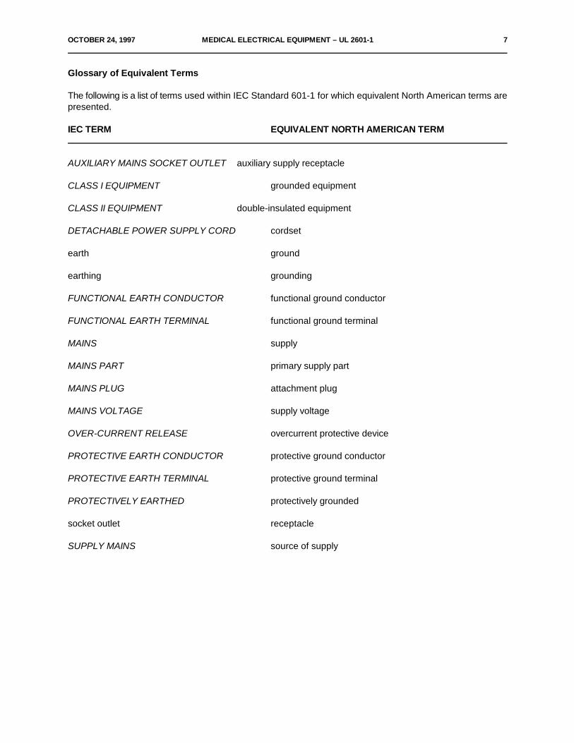
Glossary of Equivalent Terms
The following is a list of terms used within IEC Standard 601-1 for which equivalent North American terms arepresented.
IEC TERM EQUIVALENT NORTH AMERICAN TERM
AUXILIARY MAINS SOCKET OUTLET auxiliary supply receptacle
CLASS I EQUIPMENT grounded equipment
CLASS II EQUIPMENT double-insulated equipment
DETACHABLE POWER SUPPLY CORD cordset
earth ground
earthing grounding
FUNCTIONAL EARTH CONDUCTOR functional ground conductor
FUNCTIONAL EARTH TERMINAL functional ground terminal
MAINS supply
MAINS PART primary supply part
MAINS PLUG attachment plug
MAINS VOLTAGE supply voltage
OVER-CURRENT RELEASE overcurrent protective device
PROTECTIVE EARTH CONDUCTOR protective ground conductor
PROTECTIVE EARTH TERMINAL protective ground terminal
PROTECTIVELY EARTHED protectively grounded
socket outlet receptacle
SUPPLY MAINS source of supply

8 MEDICAL ELECTRICAL EQUIPMENT – UL 2601-1 OCTOBER 24, 1997
US DEVIATIONS
MEDICAL ELECTRICAL EQUIPMENT
Part 1: General requirements for safety
SECTION ONE – GENERAL
1 Scope and object
1.1 Scope
Add the following text in place of the sentence "SAFETY HAZARDS resulting from ... ":
SAFETY HAZARDS resulting from intended physiological function of EQUIPMENT covered by this Standardare not considered. These requirements do not contemplate the investigation of protection against ionizingradiation or radioactive isotopes. Such EQUIPMENT is subject to Federal radiation Standards (21CFR Part1020) promulgated under the Radiation Control for Health and Safety Act of 1968.
New 2.10.100 and 2.10.101
To reflect definitions in the NEC add the following to this sub-clause:
2.10.100 X-RAY INSTALLATIONS (LONG-TIME RATING)
A rating based on an operating interval of 5 minutes or longer.
2.10.101 X-RAY INSTALLATIONS (MOMENTARY RATING)
A rating based on an operating interval that does not exceed 5 seconds.
2.12 Miscellaneous
Add the following definitions:
2.12.100 PATIENT CARE EQUIPMENT
EQUIPMENT intended for use in or likely to be used in the PATIENT VICINITY.
OCTOBER 24, 1997 MEDICAL ELECTRICAL EQUIPMENT – UL 2601-1 9
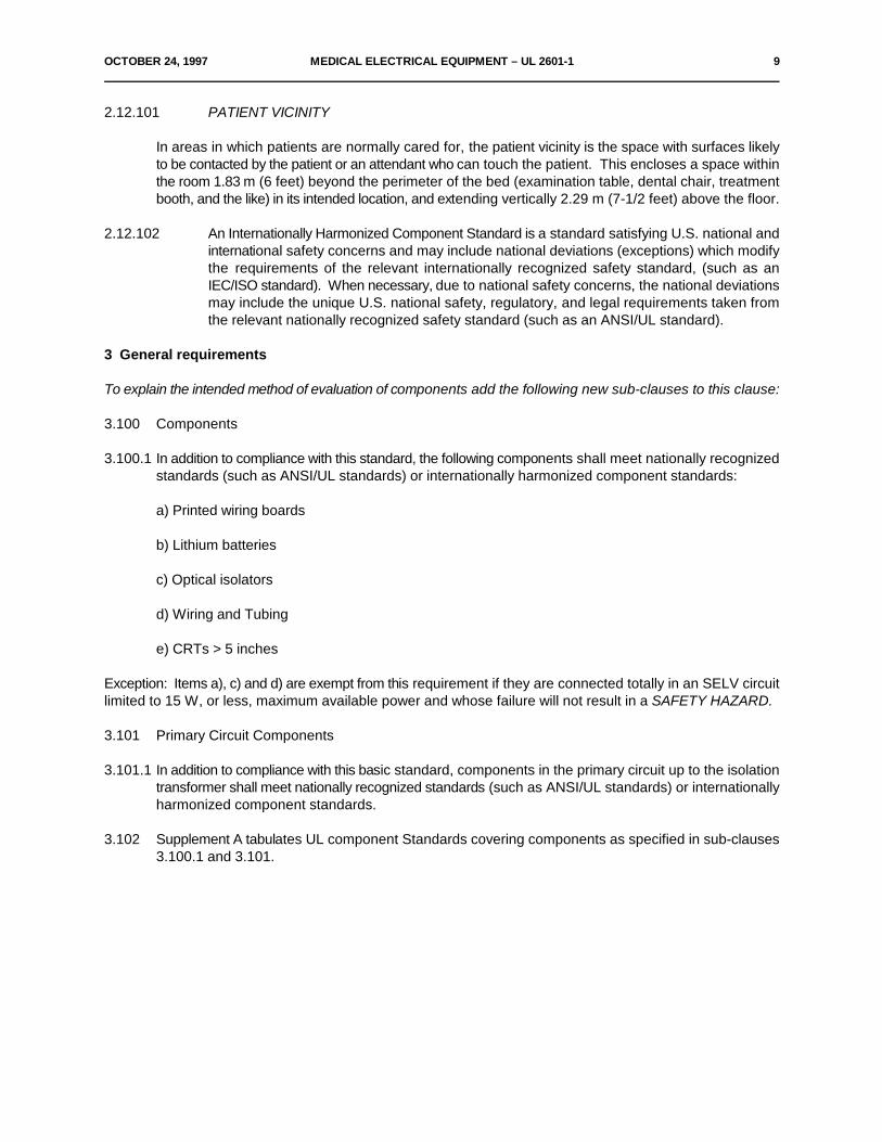
2.12.101 PATIENT VICINITY
In areas in which patients are normally cared for, the patient vicinity is the space with surfaces likelyto be contacted by the patient or an attendant who can touch the patient. This encloses a space withinthe room 1.83 m (6 feet) beyond the perimeter of the bed (examination table, dental chair, treatmentbooth, and the like) in its intended location, and extending vertically 2.29 m (7-1/2 feet) above the floor.
2.12.102 An Internationally Harmonized Component Standard is a standard satisfying U.S. national andinternational safety concerns and may include national deviations (exceptions) which modifythe requirements of the relevant internationally recognized safety standard, (such as anIEC/ISO standard). When necessary, due to national safety concerns, the national deviationsmay include the unique U.S. national safety, regulatory, and legal requirements taken fromthe relevant nationally recognized safety standard (such as an ANSI/UL standard).
3 General requirements
To explain the intended method of evaluation of components add the following new sub-clauses to this clause:
3.100 Components
3.100.1 In addition to compliance with this standard, the following components shall meet nationally recognizedstandards (such as ANSI/UL standards) or internationally harmonized component standards:
a) Printed wiring boards
b) Lithium batteries
c) Optical isolators
d) Wiring and Tubing
e) CRTs > 5 inches
Exception: Items a), c) and d) are exempt from this requirement if they are connected totally in an SELV circuitlimited to 15 W, or less, maximum available power and whose failure will not result in a SAFETY HAZARD.
3.101 Primary Circuit Components
3.101.1 In addition to compliance with this basic standard, components in the primary circuit up to the isolationtransformer shall meet nationally recognized standards (such as ANSI/UL standards) or internationallyharmonized component standards.
3.102 Supplement A tabulates UL component Standards covering components as specified in sub-clauses3.100.1 and 3.101.
10 MEDICAL ELECTRICAL EQUIPMENT – UL 2601-1 OCTOBER 24, 1997
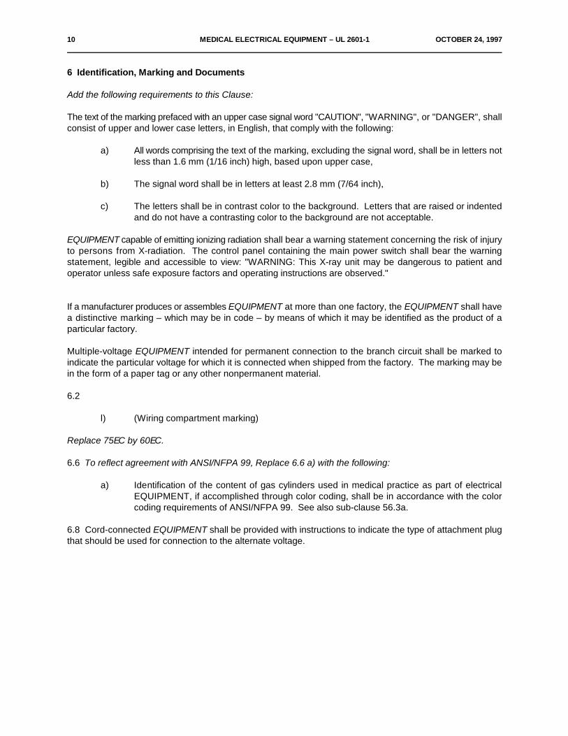
6 Identification, Marking and Documents
Add the following requirements to this Clause:
The text of the marking prefaced with an upper case signal word "CAUTION", "WARNING", or "DANGER", shallconsist of upper and lower case letters, in English, that comply with the following:
a) All words comprising the text of the marking, excluding the signal word, shall be in letters notless than 1.6 mm (1/16 inch) high, based upon upper case,
b) The signal word shall be in letters at least 2.8 mm (7/64 inch),
c) The letters shall be in contrast color to the background. Letters that are raised or indentedand do not have a contrasting color to the background are not acceptable.
EQUIPMENT capable of emitting ionizing radiation shall bear a warning statement concerning the risk of injuryto persons from X-radiation. The control panel containing the main power switch shall bear the warningstatement, legible and accessible to view: "WARNING: This X-ray unit may be dangerous to patient andoperator unless safe exposure factors and operating instructions are observed."
If a manufacturer produces or assembles EQUIPMENT at more than one factory, the EQUIPMENT shall havea distinctive marking – which may be in code – by means of which it may be identified as the product of aparticular factory.
Multiple-voltage EQUIPMENT intended for permanent connection to the branch circuit shall be marked toindicate the particular voltage for which it is connected when shipped from the factory. The marking may bein the form of a paper tag or any other nonpermanent material.
6.2
l) (Wiring compartment marking)
Replace 75EC by 60EC.
6.6 To reflect agreement with ANSI/NFPA 99, Replace 6.6 a) with the following:
a) Identification of the content of gas cylinders used in medical practice as part of electricalEQUIPMENT, if accomplished through color coding, shall be in accordance with the colorcoding requirements of ANSI/NFPA 99. See also sub-clause 56.3a.
6.8 Cord-connected EQUIPMENT shall be provided with instructions to indicate the type of attachment plugthat should be used for connection to the alternate voltage.

OCTOBER 24, 1997 MEDICAL ELECTRICAL EQUIPMENT – UL 2601-1 11
10.2.2 Power supply
a)
To reflect agreement with the NEC, replace the reference to "500 V" with "600 V" in both locations in the textassociated with the first dash, and in the text of the last dash of this sub-clause, add "and the NEC" after thereference to "IEC Publication 364".
14 Requirements related to classification
To reflect agreement with the NEC add the following requirement to this Clause:
– All FIXED EQUIPMENT and PERMANENTLY INSTALLED EQUIPMENT shall be CLASS I EQUIPMENT.
18 Protective earthing, functional earthing and potential equalization
Add the following to this Clause:
m) All parts of X-ray EQUIPMENT operating at over 600 V ac, 850 V dc, or 850 V peak shall beenclosed within protectively earthed (grounded) enclosures. The connections from the high-voltage EQUIPMENT to X-ray tubes and other high-voltage components shall be made withhigh-voltage shielded cables intended for operation at over 600 V ac, 850 V dc, or 850 V peak.
n) All accessible non-current carrying conductive parts, likely to become energized, of X-ray andassociated EQUIPMENT (controls, tables, transformer tanks, shields of shielded cables, tubeheads and supports, etc.) shall be protectively earthed (grounded) in accordance with Clause18.
19 Continuous LEAKAGE CURRENTS and PATIENT AUXILIARY CURRENTS
In addition to the Clause 19 requirements, the following requirements apply, except that X-ray EQUIPMENTand EQUIPMENT covered by note 3) on Table IV of the base standard need only comply with Clause 19requirements.
The leakage currents specified in Tables 19.100 and 19.101 are not to be exceeded when the EQUIPMENTis tested in accordance with Clause 19 except:
– The EQUIPMENT is to be connected to the highest RATED MAINS VOLTAGE 1)
– The footnotes in Tables 19.100 and 19.101 apply.
1) Minimum 120 VAC and 240 VAC for EQUIPMENT with marked voltage ranges of 105-120 VAC and 210-240VAC respectively.
12 MEDICAL ELECTRICAL EQUIPMENT – UL 2601-1 OCTOBER 24, 1997
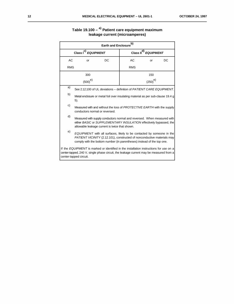
Table 19.100 – Patient care equipment maximuma)
leakage current (microamperes)
Earth and Enclosureb)
Class I EQUIPMENT Class II EQUIPMENTc) d)
AC or DC AC or DC
RMS RMS
300 150
(500) (250)e) e)
See 2.12.100 of UL deviations – definition of PATIENT CARE EQUIPMENT.a)
Metal enclosure or metal foil over insulating material as per sub-clause 19.4 gb)
5).
Measured with and without the loss of PROTECTIVE EARTH with the supplyc)
conductors normal or reversed.
Measured with supply conductors normal and reversed. When measured withd)
either BASIC or SUPPLEMENTARY INSULATION effectively bypassed, theallowable leakage current is twice that shown.
EQUIPMENT with all surfaces, likely to be contacted by someone in thee)
PATIENT VICINITY (2.12.101), constructed of nonconductive materials maycomply with the bottom number (in parentheses) instead of the top one.
If the EQUIPMENT is marked or identified in the installation instructions for use on acenter-tapped, 240 V, single phase circuit, the leakage current may be measured from acenter-tapped circuit.
OCTOBER 24, 1997 MEDICAL ELECTRICAL EQUIPMENT – UL 2601-1 13
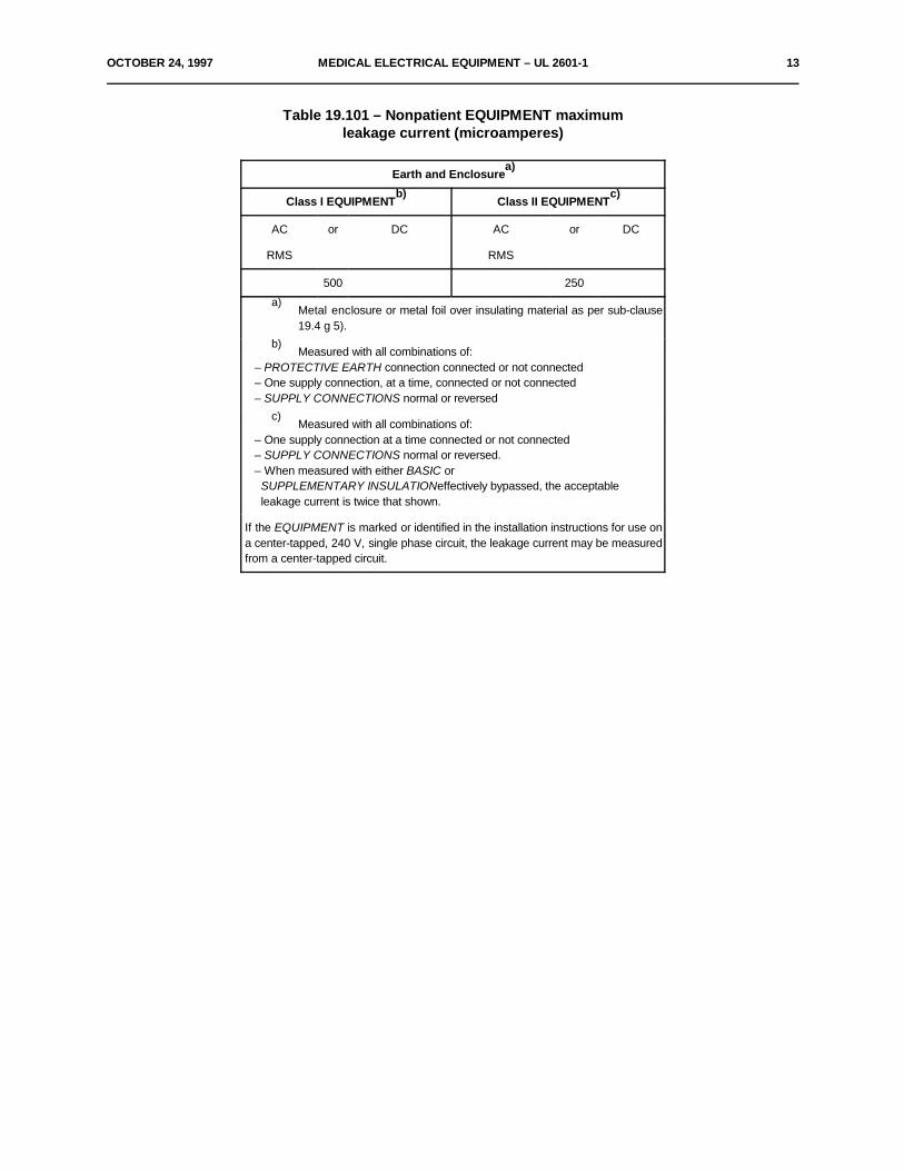
Table 19.101 – Nonpatient EQUIPMENT maximumleakage current (microamperes)
Earth and Enclosurea)
Class I EQUIPMENT Class II EQUIPMENTb) c)
AC or DC AC or DC
RMS RMS
500 250
Metal enclosure or metal foil over insulating material as per sub-clausea)
19.4 g 5).
Measured with all combinations of:b)
– PROTECTIVE EARTH connection connected or not connected – One supply connection, at a time, connected or not connected – SUPPLY CONNECTIONS normal or reversed
Measured with all combinations of:c)
– One supply connection at a time connected or not connected – SUPPLY CONNECTIONS normal or reversed. – When measured with either BASIC or SUPPLEMENTARY INSULATIONeffectively bypassed, the acceptable leakage current is twice that shown.
If the EQUIPMENT is marked or identified in the installation instructions for use ona center-tapped, 240 V, single phase circuit, the leakage current may be measuredfrom a center-tapped circuit.

14 MEDICAL ELECTRICAL EQUIPMENT – UL 2601-1 OCTOBER 24, 1997
22 Moving parts
Add the following requirement to this Clause:
– Where a risk of injury to the patient or operator can occur as a result of a moving part, in addition tothe other requirements in this clause, there shall be end stops or other mechanical means to act asthe ultimate travel limiting means (example: the end points of a movable ceiling suspension).
End stops or other mechanical means shall have the mechanical strength to withstand the conditionsof maximum intended loading and reasonably foreseeable abusive operation.
Compliance with these requirements shall be determined by the following tests.
The EQUIPMENT shall be loaded with (1) the maximum intended load, (2) unloaded, or (3) loaded toany intermediate level that is likely to provide the most severe test result. The moving part is to bedriven against each end stop or other mechanical means for the number of cycles and conditionsshown in the following Table. The end stops or other mechanical means required shall be capable ofperforming their intended function upon completion of the following tests.

OCTOBER 24, 1997 MEDICAL ELECTRICAL EQUIPMENT – UL 2601-1 15
Table 22.100 – Number of Test Cycles
Construction No. Cycles Test Conditions
Motor driven
1. No limit system
provided 6000 Run at maximum speeda
2. Non-independent limit
system or systems Defeat all switches
provided 50 simultaneously, and run ata,b
maximum speed
3. Two or more independent
limit systems No Testa,b
Manually driven or Run at any speed, including
manually driven power assisted 50 reasonable overspeed considered
to be abusive
A limit system consists of all components required to stop motion, for example, ita
may consist of (1) a limit switch, (2) sensing circuits, and (3) related mechanicalactuating mechanism.
To qualify as an independent limit system, each system shall, in addition to theb
criteria in note , comply with both of the following:a
1. The system is capable of de-energizing the motor(s) directly; that is, theswitch or motor controller circuit interrupts the motor's rotor or statorcurrent, or both, and
2. The system provides a means by which a malfunction of one limit systemis made obvious to the operator. This may be an audible, visual orotherwise discernible indicator.
22.4
In addition to "PATIENT" add "or OPERATOR" to the requirement in this sub-clause.
22.7
Add the following requirements to this sub-clause:
– A device intended to be designated as an emergency off, emergency switching or stopping deviceshall comply with each of the following:
a) The device shall be constructed in accordance with all of the following:
16 MEDICAL ELECTRICAL EQUIPMENT – UL 2601-1 OCTOBER 24, 1997
1) The device shall have an actuator, colored red as per 6.7, designed to be distinctiveand easily identifiable from that of other controls, and that will open the circuit(s) whenactuated,
2) The device, once actuated, shall maintain the EQUIPMENT in the off (open) conditionuntil a deliberate action, different from that used to actuate it, is performed, and,
3) Actuators shall be readily accessible to the OPERATOR and positioned at eachoperating station.
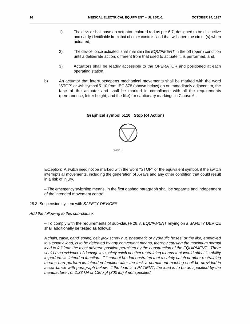
b) An actuator that interrupts/opens mechanical movements shall be marked with the word"STOP" or with symbol 5110 from IEC 878 (shown below) on or immediately adjacent to, theface of the actuator and shall be marked in compliance with all the requirements(permanence, letter height, and the like) for cautionary markings in Clause 6.
Graphical symbol 5110: Stop (of Action)
Exception: A switch need not be marked with the word "STOP" or the equivalent symbol, if the switchinterrupts all movements, including the generation of X-rays and any other condition that could resultin a risk of injury.
– The emergency switching means, in the first dashed paragraph shall be separate and independentof the intended movement control.
28.3 Suspension system with SAFETY DEVICES
Add the following to this sub-clause:
– To comply with the requirements of sub-clause 28.3, EQUIPMENT relying on a SAFETY DEVICEshall additionally be tested as follows:
A chain, cable, band, spring, belt, jack screw nut, pneumatic or hydraulic hoses, or the like, employedto support a load, is to be defeated by any convenient means, thereby causing the maximum normalload to fall from the most adverse position permitted by the construction of the EQUIPMENT. Thereshall be no evidence of damage to a safety catch or other restraining means that would affect its abilityto perform its intended function. If it cannot be demonstrated that a safety catch or other restrainingmeans can perform its intended function after the test, a permanent marking shall be provided inaccordance with paragraph below. If the load is a PATIENT, the load is to be as specified by themanufacturer, or 1.33 kN or 136 kgf (300 lbf) if not specified.
OCTOBER 24, 1997 MEDICAL ELECTRICAL EQUIPMENT – UL 2601-1 17
The EQUIPMENT shall be marked with signal word "WARNING" and the following text or theequivalent - "For Continued Protection Against Injury to Persons, Repair or Replace Safety Catch (orspecific restraining means, as appropriate) After It Has Been Activated. Refer to Instructions in theService Manual Provided With the Equipment." The marking shall be readily visible during anyapproach to servicing or resetting of the safety catch. More than one such marking may be required.
28.4 Suspension systems of metal without SAFETY DEVICES
Add the following to this sub-clause:
– To comply with the required SAFETY FACTORS, the suspensions shall be subjected to a loadingtest.
The suspension shall be loaded as in normal use with its SAFE WORKING LOAD multiplied by theapplicable SAFETY FACTORS. There shall be no damage to structural parts that would create a riskof injury to a PATIENT or OPERATOR. The support system shall be in equilibrium one minute afterapplication of the test load. The test may be conducted on previously untested samples.
28 Suspended masses
Replace the last paragraph (after 28.4) with the following:
Compliance with the requirements of sub-clause 28.3 and 28.4 is checked by test performance, design dataand inspection of any maintenance instructions.
Exception: Where the complexity of the system is such that the design data can be reasonably evaluated soas to determine that compliance is met, demonstration of test performance may not be necessary.
SECTION FIVE – PROTECTION AGAINST HAZARDS FROM UNWANTEDOR EXCESSIVE RADIATION
Add the following explanation to this Section:
The requirements of sub-clause 29.2 shall be considered when evaluating EQUIPMENT. The remainingSECTION FIVE items are considered the responsibility of the proper authorities. See sub-clause 1.1 of the ULDeviations.

18 MEDICAL ELECTRICAL EQUIPMENT – UL 2601-1 OCTOBER 24, 1997
SECTION SEVEN – PROTECTION AGAINST EXCESSIVE TEMPERATURES ANDOTHER SAFETY HAZARDS
Add the following to this section:
400 Oxygen
400.0 General – These requirements only apply to EQUIPMENT that is normally used or recommended foruse with oxygen or oxygen enriched atmospheres and for which no Particular requirements exist thataddress the EQUIPMENT'S use with oxygen or oxygen enriched atmospheres. Sub-clauses 400.8.1– 400.8.5 are relevant to installation and the product's end use and can be addressed by their inclusionin the product's operation and installation manual. The manual's reference should cover those detailsneeded to reduce the risk of oxygen related hazards.
400.1 In order to reduce the risk of fire caused by electrical components which might be a source of ignitionin oxygen- enriched atmospheres, at least one of the following requirements shall be satisfied inenclosed compartments of EQUIPMENT containing such atmospheres:
– Electrical components shall be separated from compartments in which accumulation of oxygen canoccur, by a barrier complying with the requirements of sub-clause 400.2.
– Compartments containing electrical components shall be ventilated according to the requirementsof Sub-clause 400.3.
– Electrical components which, in NORMAL USE or SINGLE FAULT CONDITIONS can be a sourceof ignition, shall comply with the requirements of Sub-clause 400.4.
Exception: EQUIPMENT that is marked as specified in sub-clauses 400.6 and 400.7 or does not containan oxygen enriched environment within the EQUIPMENT need not comply with sub-clauses400.1 – 400.5 and 400.8.1 – 400.8.5.
400.2 Any barrier required under the provision of Sub-clause 400.1 shall be sealed at all joints and at anyholes for cables, shafts or for other purposes.
Compliance is checked by inspection and, if applicable, by the compliance test described in theGeneral Standard, Sub-clause 40.5, for enclosures with restricted breathing.
The internal overpressure of 4 hPa specified in Sub-clause 40.5 of the General Standard is notapplicable when, in NORMAL CONDITION, a pressure difference exists between the spaces separatedby the barrier. In such cases the compliance test of Sub-clause 400.3 of this Particular Standardapplies.
400.3 The ventilation required under the provisions of Sub-clause 400.1 shall be such that the oxygen contentin the compartment containing electrical components shall not exceed 4 per cent volume above theambient level. If this requirement is met by forced ventilation a ventilation failure alarm shall beprovided.
Compliance is checked by the following test:
The oxygen concentration is measured under the following conditions and for such a period that thehighest possible concentration of oxygen occurs:
OCTOBER 24, 1997 MEDICAL ELECTRICAL EQUIPMENT – UL 2601-1 19
– SINGLE FAULT CONDITION.
– The oxygen flow shall be equal to the maximum set-point value in NORMAL USE.
– Selection of the least favorable control settings.
– Mains supply voltage deviations of ±10 percent.
– The measurements shall be repeated after 18 h during which the time the supply voltage shall havebeen switched off and the gas supply shall have remained on.
– The rate of air exchange in the test room shall be between 3 and 10 times per hour.
400.4 Electrical circuits which can produce sparks or generate increased surface temperatures or whichmight otherwise be a source of ignition shall be so designed that no ignition occurs. At least thefollowing requirements shall be satisfied in NORMAL CONDITIONS and SINGLE FAULTCONDITIONS:
– The product of the value of the rms no load voltage and the rms value of the short circuit currentshall not exceed 10 VA.
– The surface temperature of components shall not exceed 300EC.
Compliance is checked by the following test:
Voltages and currents in steady-state condition are measured or calculated and surface temperaturesshall be measured in NORMAL CONDITIONS and SINGLE FAULT CONDITIONS.
Note – Short- and open-circuiting of resistors, capacitors and inductances complying with the requirements of IEC Publication 65,fourth edition, Clause 14, shall not be considered as SINGLE FAULT CONDITIONS.
400.5 External exhaust gas outlets shall be located at least 20 cm from any electrical component mountedon the outside of the EQUIPMENT which can spark in NORMAL CONDITION or SINGLE FAULTCONDITION.
Compliance is checked by inspection and/or measurement.
400.6 Hospital beds intended for use with oxygen administering EQUIPMENT shall be marked with thefollowing notice or equivalent wording: "CAUTION – Possible fire hazard when used with oxygenadministering EQUIPMENT of other than the nasal, mask or 1/2 bed length tent type. Oxygen tentshould not extend below mattress support level". An additional statement "Lock hand control at footof bed when using oxygen administrating equipment," or similar wording shall be included whereapplicable (see sub-clause 400.4). The letter height shall not be less than 2.8 mm (7/64 inch) for theword "CAUTION" and not less than 2.4 mm (3/32 inch) for the remainder of the notice. The markingshall be located on the outside vertical surface of the foot panel of the bed where readily visible.
20 MEDICAL ELECTRICAL EQUIPMENT – UL 2601-1 OCTOBER 24, 1997
400.7 When provided on beds intended for use with oxygen administering EQUIPMENT, pendant controlsfor patient use which have not been found suitable for use in oxygen atmosphere shall be marked"CAUTION – Possible fire hazard if hand control is not locked at foot of bed when using oxygenadministering equipment", or with an equivalent wording. The letter height shall not be less than2.8 mm (7/64 inch) for the word "CAUTION" and not less than 2.4 mm (3/32 inch) for the remainderof the notice.
400.8 Installation Related Items
400.8.1 The use of oxygen in therapy requires that special care be taken to prevent fire. Any materials whichwill burn in air and some that will not are easily ignited and burn rapidly in high concentrations ofoxygen. Accordingly, for safety it is necessary that all sources of ignition be kept away fromEQUIPMENT, such as an incubator, and preferably out of the room in which it is being used. "NOSMOKING" signs should be prominently displayed.
400.8.2 A spontaneous and violent ignition may occur if oil, grease or greasy substances come in contact withoxygen under pressure. These substances must be kept away from oxygen regulators, cylinder valves,tubing and connections, and all other oxygen EQUIPMENT.
400.8.3 On high pressure oxygen cylinders, use only approved reducing or regulating valves marked for oxygenservice. Do not use these valves for air or gases other than oxygen, since they may be hazardouswhen returned to oxygen service. Such EQUIPMENT must be operated strictly in accordance withmanufacturer's directions.
400.8.4 In view of these considerations, and to avoid the necessity for handling heavy cylinders in the nursery,it is recommended that wherever possible, the high pressure oxygen EQUIPMENT be located outsidethe nursery. In any event, cylinders in use should be fixed in place so they will not be knocked over,and should be located as far as practicable from the incubator.
400.8.5 Mixtures of oxygen and flammable vapors, such as alcohol, ether, ethylene and cyclopropane mayexplode if ignited. Such mixtures may be ignited by electrical static spark discharges, or hightemperature surfaces, in addition to all other more common sources of ignition. Only EQUIPMENTdesigned for use in hazardous locations should be used in operating and delivery rooms. Refer toArticle 517 of the ANSI/NFPA 70, National Electrical Code, for the use of flammable anesthetics.
42 Excessive temperatures
Add the following requirements to this Clause:
Insulating systems (such as on transformers, motors, solenoids, inductors and the like) where the measuredtemperatures exceed Class A (105EC) limits during normal use and normal condition shall comply with therequirements in the Standard for Systems of Insulating Materials - General (UL 1446).
OCTOBER 24, 1997 MEDICAL ELECTRICAL EQUIPMENT – UL 2601-1 21
52.4.1
Editorial: Replace the reference to "Table XII" in the text adjacent to the third dash with "Table XI".
Replace the second paragraph of this sub-clause with the following text:
The requirements of sub-clause 52.1 and the corresponding tests shall not be applied to components whentheir construction or the supply circuit limits the power dissipation in SINGLE FAULT CONDITION to 15W orless.
Editorial: Replace the information in the first column, lower box, adjacent to the first dash (-) with the followingtext:
– if impedance-protected, maximum value.
54 General
Editorial: Replace the second sentence of the third paragraph with the following text:
The requirements of this Section are not to be considered the only means of achieving the required degree ofsafety and the term "shall", where used, should be understood accordingly.
22 MEDICAL ELECTRICAL EQUIPMENT – UL 2601-1 OCTOBER 24, 1997
55 ENCLOSURES and covers
Add the following requirement to this Clause:
The following requirements are additionally used to evaluate polymeric enclosures and covers:
Conductive coatings applied to nonmetallic surfaces shall comply with the applicable requirements in theStandard for Polymeric Materials – Use in Electrical Equipment Evaluations, UL 746C, unless it can bedetermined by investigation that flaking or peeling of the coating does not result in the reduction of spacingsor the bridging of live parts that may present a risk of injury.
– Flame Spread – An external surface of combustible material having an area of more than 9.47 sqM (100 sq-ft) or a single dimension of 3.7 M (12 feet) – including a diagonal – shall have a flame spread rating of 75 orless when subjected to the Steiner Tunnel Test in ASTM E 84, Test Method for Surface Burning Characteristicsof Building Materials).
An external surface of combustible material having an area of more than 4.74 sqM (50 sq-ft) but not exceeding9.47 sqM (100 sq-ft) shall have a flame spread rating of 75 or less when subjected to the radiant panel test(ASTM E 162, Test Method for Surface Flammability of Materials Using a Radiant Heat Energy Source), or thesteiner tunnel test (ASTM E 84, Test Method for Surface Burning Characteristics of Building Materials).
– Flammability, Mechanical Abuse and Mold Stress Relief - In addition to the other requirements in thisStandard, flammability, mechanical abuse and mold stress tests shall be conducted. Polymeric enclosuresand covers shall comply with the requirements for resistance to impact and drop as indicated below, and therequirements for mold stress release distortion, in the Standard for Polymeric Materials – Use in ElectricalEquipment Evaluations, UL 746C. The minimum flammability rating for TRANSPORTABLE EQUIPMENT shallbe V-2, and V-0 for FIXED EQUIPMENT or STATIONARY EQUIPMENT.
Exception for Flammability. Enclosures housing only circuits supplied from a source which is separated fromthe SUPPLY MAINS by one of the methods described in Subclause 17g, and where the available power doesnot exceed 15 W.
The top, sides, and front of the enclosure shall withstand a single impact of 6.78 N@m (5 ft-lb) without exposinglive electrical components or connections or developing a risk of electric shock, fire, or injury to persons. Theimpact applied is to be obtained from a solid, smooth, steel sphere 50.8 mm (2 inch) in diameter and weighingapproximately 0.535 kg (1.18 lb). The sphere is allowed to fall freely from rest through the distance requiredto cause it to strike the top of the enclosure with an impact of 6.78 N@m (5 ft-lb). For surfaces other than thetop of the enclosure the sphere is to be suspended by a cord and allowed to fall as a pendulum through thedistance required to strike the surface with the specified impact. The enclosure is placed so that the surfacetested is vertical and in the same vertical plane as the point of support of the pendulum. Parts of the enclosurethat may interfere with the cord of the pendulum are to be removed.
An appliance intended to be hand-held or hand-guided shall withstand a drop test without exposing liveelectrical components or connections or developing a risk of electric shock, fire, or injury to persons. Each ofthree samples of the appliance is to be dropped three times from a height of 1.22 m (4 ft) onto an tile coveredconcrete surface, in such manner as to test the component whose failure would create a risk of fire or electricshock in the most severe manner.
– See also Clause 16, Clause 21 and sub-clause 59.2
OCTOBER 24, 1997 MEDICAL ELECTRICAL EQUIPMENT – UL 2601-1 23
56.3 Connections – General
a) Construction of connectors
Add the following requirement to this sub-clause:
A connector, plug, pin, or the like that is attached to a patient-connected lead or contact shall be constructedso that it cannot engage any part on the EQUIPMENT – including a separable cord set – that can introduce arisk of electric shock, fire, or injury to persons.
In addition to the above requirement, a connector, plug, pin or the like that is attached to a patient-connectedlead or contact, and that is used with a product that may be used without professional supervision, shall beconstructed so that it cannot be inserted or otherwise manipulated to make contact with the live parts of a powerreceptacle outlet or separable cord set.
57 MAINS PARTS, components and layout
Add the following requirement to this Clause:
– General – Permanently connected EQUIPMENT shall have provision for the connection of one ofthe wiring systems that is in accordance with the National Electrical Code, ANSI/NFPA 70.
Exception: Fixed and stationary X-ray EQUIPMENT supplied from a branch circuit rated at 30 A orless, and EQUIPMENT that is not strictly portable but obviously is intended to be stationary, may beacceptable if provided with a length of attached hard service flexible cord - such as Type S, or theequivalent, for supply connection.
57.2 MAINS CONNECTORS, APPLIANCE INLETS and the like
Add the following new requirements to this Sub-clause:
For patient care equipment, where a "Hospital Grade" or "Hospital Only" MAINS PLUG exists for the particularelectrical rating in question, the MAINS PLUG of non-PERMANENTLY INSTALLED EQUIPMENT with aprotective earth connection shall comply with the requirements for a hospital grade attachment plug (mainsplug) or the non-hazardous location locking type designated "Hospital Only" as specified in the Standard forAttachment Plugs and Receptacles UL 498 and the product shall comply with the following:
Cord connected EQUIPMENT employing "Hospital Only" or "Hospital Grade" attachment plugs shall beprovided with instructions to indicate that grounding reliability can only be achieved when the EQUIPMENT isconnected to an equivalent receptacle marked "Hospital Only" or "Hospital Grade". The necessary instructionsshall be included on the EQUIPMENT itself or on a tag attached to the supply cord of the EQUIPMENT.
– For EQUIPMENT intended for radiography and in which the plug constitutes the control-disconnecting means,the attachment plug shall be acceptable for a current not less than 50 percent of the maximum current inputto the EQUIPMENT for radiographic settings.
24 MEDICAL ELECTRICAL EQUIPMENT – UL 2601-1 OCTOBER 24, 1997
– Except for X-ray EQUIPMENT, the attachment plug shall be acceptable for use with a current not less than125 percent of the rated current, when measured at a voltage equal to the rated voltage of the EQUIPMENT(corresponding to the plug cap configuration). If the EQUIPMENT is intended for being adapted for use on twoor more different values of voltage by field alteration of internal connections, the attachment plug provided withthe EQUIPMENT shall be acceptable for the voltage for which the EQUIPMENT is configured to be connectedwhen shipped from the factory.
– If a polarized attachment plug is used, the circuit conductors in the flexible cord shall be connected to the plugand to the wiring in the EQUIPMENT so that any of the following devices used in the primary circuit shall beconnected in an ungrounded side of the line: the center contact of an edison-base lampholder, a single poleswitch, an automatic control with a marked off position, a solitary fuseholder, and any other single-poleovercurrent protective device.
Exception: If a second fuseholder or other overcurrent protective device is provided in the application, it maybe placed in the grounded side of the line.
57.3 POWER SUPPLY CORDS
Replace the text of b) and c) of this sub-clause with the following requirements:
b) Types
A DETACHABLE POWER SUPPLY CORD for non-PERMANENTLY INSTALLEDEQUIPMENT (cord-connected EQUIPMENT) shall be of a type that can be shown to beunlikely to become detached accidentally, unless it can be shown that detachment will notconstitute a SAFETY HAZARD to a PATIENT or OPERATOR.
A POWER SUPPLY CORD shall comply with the following requirements:
1) The flexible cord shall be of a type that is acceptable for the particular application.It shall be acceptable for use at a voltage not less than the rated voltage of theappliance and shall have an ampacity, as given in the National Electrical Code,ANSI/NFPA No. 70, not less than the current rating of the appliance. It shall beconstructed in accordance with the Standard for Flexible Cords and Fixture Wire (UL62) or the equivalent Appliance Wiring Material (AWM).
2) The flexible cord shall be not smaller than No. 18 AWG, and the mechanicalserviceability shall be
i) not less than that of Type SJE, SJT, SJO, or equivalent cord, forTRANSPORTABLE EQUIPMENT such as hospital beds and instrumentcarts; and
ii) not less than that of Type SV for light-duty EQUIPMENT where extremeflexibility or weight is a factor. EQUIPMENT weighing 567 g (1-1/4 lb) or lesswould qualify for consideration.
iii) An oil-resistant cord is required if the EQUIPMENT is likely to be subjectedto grease or oil.
OCTOBER 24, 1997 MEDICAL ELECTRICAL EQUIPMENT – UL 2601-1 25
57.5 MAINS TERMINAL DEVICES and wiring of MAINS PARTS
b) Arrangement of MAINS TERMINAL DEVICES
Add the following requirements to this Sub-clause:
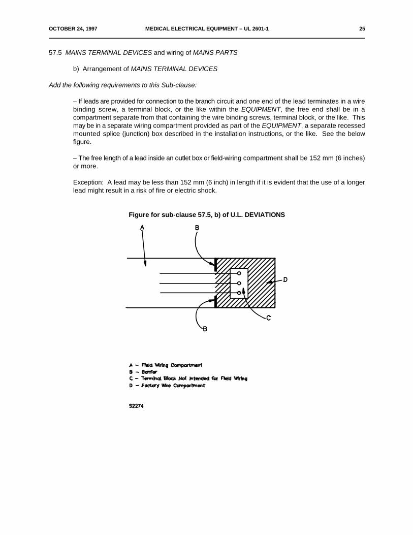
– If leads are provided for connection to the branch circuit and one end of the lead terminates in a wirebinding screw, a terminal block, or the like within the EQUIPMENT, the free end shall be in acompartment separate from that containing the wire binding screws, terminal block, or the like. Thismay be in a separate wiring compartment provided as part of the EQUIPMENT, a separate recessedmounted splice (junction) box described in the installation instructions, or the like. See the belowfigure.
– The free length of a lead inside an outlet box or field-wiring compartment shall be 152 mm (6 inches)or more.
Exception: A lead may be less than 152 mm (6 inch) in length if it is evident that the use of a longerlead might result in a risk of fire or electric shock.
Figure for sub-clause 57.5, b) of U.L. DEVIATIONS
26 MEDICAL ELECTRICAL EQUIPMENT – UL 2601-1 OCTOBER 24, 1997
57.9.1 Overheating
(Transformer Short Circuit and Overload): Add the following explanation to this sub-clause:
For an electronic circuit used to comply with the requirements of this sub-clause a fuse or manual resetprotector may be left in the circuit. If such components have not been investigated (such as those notinvestigated for calibration of opening for time vs. current or temperature) and functions to terminate the test,the test shall be repeated two additional times. For the overload test the maximum loading not resulting in thecircuit switching to its limiting mode is to be used until the ultimate results. This requirement is not an alternativeto enable the use of fuses, breakers, and the like that do not comply with the U. S. Deviation to Clause 3.
A positive temperature coefficient resistive device (PTC) is to be left in the circuit for the short circuit test untilultimate results. For the overload test the maximum loading not resulting in the PTC switching to its highresistance mode is to be used until ultimate results are known.
58.2
Add the following requirements to this sub-clause:
Soldering alone shall not be used. Connections shall be made mechanically secure as well as beingsoldered.
59.1 Internal wiring
f) Applicable requirements
Replace the requirement contained in sub-section f) with the following:
The installation of connecting cords between EQUIPMENT parts shall meet the requirementsof the NEC, as applicable.
In addition to the requirements in this standard, a cable used as external interconnectionbetween units shall be as follows:
1) If exposed to abuse, the cable shall be Type SJT, SJTO, SJO, ST, SO, STO, orequivalent flexible cord or similar multiple-conductor appliance-wiring material suchas computer cable.
2) If not exposed to abuse, the cable shall be as indicated in item 1) above or shall be:
i) Type SPT-2, SP-2, or SPE-2, or equivalent,
ii) Type SVT, SVTO, SVE, or equivalent flexible cord or similar multiple-conductor appliance-wiring material, or
OCTOBER 24, 1997 MEDICAL ELECTRICAL EQUIPMENT – UL 2601-1 27
iii) An assembly of insulated wires each with a nominal insulation thickness of0.8 mm (1/32 inch) or more, enclosed in acceptable insulating tubing havinga nominal wall thickness of 0.8 mm (1/32 inch) or more.
Exception: Interconnecting cables operating at a voltage not exceeding 25 Vac (RMS) or 60 Vdc or peaksupplied from a source which is seperated from the SUPPLY MAINS by one of the methods described inSubclause 17g.
If exposed to abuse, flexible cord or cable is considered protected from abuse from a rollingtable or similar EQUIPMENT at a time when such EQUIPMENT is likely to be used in thevicinity of the EQUIPMENT if one or more of the following conditions are met:
a) The entire cord or cable is 914 mm (3 ft) or more above the floor.
b) The cord or cable is guarded from contact by such EQUIPMENT. A cord or cablethat may touch the floor under any condition of intended use is to be consideredexposed to abuse, or
c) The entire cord or cable, which may be a retractable helically coiled type constructedso as to retain its retractability, supplies a hand-held device. The cord length is limitedso that the unstretched cord does not contact the floor while the control device is inthe stored position or while the control device is positioned 610 mm (2 ft) above thefloor.
28 MEDICAL ELECTRICAL EQUIPMENT – UL 2601-1 OCTOBER 24, 1997
Add the following Clause:
600 Separate Power Units
600.1 General
A separate power unit (adapter, power supply, battery charger, or the like) employing a separable connectorfor supplying the EQUIPMENT shall be, (a) packaged with the EQUIPMENT, or , (b) be referenced by thefollowing or equivalent marking on the EQUIPMENT:
"_______ (equipment descriptive name) ______ Model _______." "Use only with (manufacturer's name orequivalent) Model ____ Adapter (power supply, battery charger, or the like)", or "Use only with adapters (or thelike) noted in the instruction manual." If a reference is made to a manual, the manual shall be provided withthe EQUIPMENT and shall clearly tabulate the adapters (or the like) with which the EQUIPMENT is intendedto be used by manufacturer's name and model number. Also, the EQUIPMENT shall be marked with Symbol14 of Table DI in Appendix D, if a reference is made to a manual.
600.2 Direct Plug-In Units
These requirements supplement the requirements in this Standard.
600.2.1 Construction
A direct plug-in unit shall comply with the mechanical assembly, enclosure, input connections, accessibility oflive parts, and grounding requirements specified in UL 1310, the Standard for Class 2 Power Units.
600.2.2 Performance
A direct plug-in unit shall comply with the direct plug-in requirements for blade secureness, security of inputcontacts, and abuse tests specified in UL 1310, the Standard for Class 2 Power Units.
During the tests specified in Sub-clause 57.9.1 a) and 57.9.1 b), the external enclosure temperature rise of adirect plug-in unit shall not exceed 65EC, except a temperature rise of 125EC is acceptable if the unitpermanently opens within one hour after initiation of the test.
OCTOBER 24, 1997 MEDICAL ELECTRICAL EQUIPMENT – UL 2601-1 29
600.2.3 Markings
A direct plug-in unit provided with a mounting tab shall be marked in accordance with the requirements forsemipermanent mounted units specified in UL 1310, the Standard for Class 2 Power Units.
FIG. 18 – Measuring Circuit for the ENCLOSURE LEAKAGE CURRENT of EQUIPMENT
Editorial: In order to be consistent with Figure 19, replace the script "S5" at the top of the Figure with "S9".
Legends of Symbols for FIGS. 10 to 27
Editorial: Add to the list of legends the following text.
R Impedance for protection of user of test apparatus.
MANUFACTURING AND PRODUCTION TESTS
Note – Clauses 700 through 702 are informative and are not to be considered an integral part of the U.S.Deviations.
700 Production-Line Dielectric Voltage-Withstand Test
700.1 Each appliance shall withstand without an indication of unacceptable performance, as a routineproduction-line test, the application of a 40 – 70 Hz potential or a d.c. potential of 1.414 times the stated a.c.value between:
a) The primary wiring, including connected components, and accessible dead metal parts that arelikely to become energized, and
b) Primary and accessible low voltage (42.4 volt peak or less) metal parts, including terminals, and,where applicable
c) Primary circuits and patient-connected circuits.
700.2 The production-line test shall be in accordance with either condition A or condition B of Table 700.1.
700.3 The appliance may be in a heated or unheated condition for the test.
30 MEDICAL ELECTRICAL EQUIPMENT – UL 2601-1 OCTOBER 24, 1997
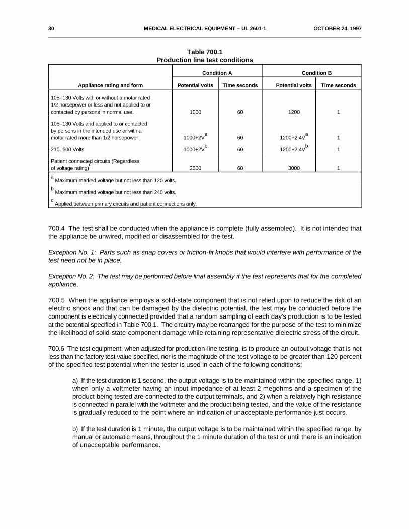
Table 700.1Production line test conditions
Appliance rating and form Potential volts Time seconds Potential volts Time seconds
Condition A Condition B
105–130 Volts with or without a motor rated1/2 horsepower or less and not applied to orcontacted by persons in normal use. 1000 60 1200 1
105–130 Volts and applied to or contactedby persons in the intended use or with amotor rated more than 1/2 horsepower 1000+2V 60 1200+2.4V 1
a a
210–600 Volts 1000+2V 60 1200+2.4V 1b b
Patient connected circuits (Regardlessof voltage rating) 2500 60 3000 1
c
Maximum marked voltage but not less than 120 volts.a
Maximum marked voltage but not less than 240 volts.b
Applied between primary circuits and patient connections only.c
700.4 The test shall be conducted when the appliance is complete (fully assembled). It is not intended thatthe appliance be unwired, modified or disassembled for the test.
Exception No. 1: Parts such as snap covers or friction-fit knobs that would interfere with performance of thetest need not be in place.
Exception No. 2: The test may be performed before final assembly if the test represents that for the completedappliance.
700.5 When the appliance employs a solid-state component that is not relied upon to reduce the risk of anelectric shock and that can be damaged by the dielectric potential, the test may be conducted before thecomponent is electrically connected provided that a random sampling of each day's production is to be testedat the potential specified in Table 700.1. The circuitry may be rearranged for the purpose of the test to minimizethe likelihood of solid-state-component damage while retaining representative dielectric stress of the circuit.
700.6 The test equipment, when adjusted for production-line testing, is to produce an output voltage that is notless than the factory test value specified, nor is the magnitude of the test voltage to be greater than 120 percentof the specified test potential when the tester is used in each of the following conditions:
a) If the test duration is 1 second, the output voltage is to be maintained within the specified range, 1)when only a voltmeter having an input impedance of at least 2 megohms and a specimen of theproduct being tested are connected to the output terminals, and 2) when a relatively high resistanceis connected in parallel with the voltmeter and the product being tested, and the value of the resistanceis gradually reduced to the point where an indication of unacceptable performance just occurs.
b) If the test duration is 1 minute, the output voltage is to be maintained within the specified range, bymanual or automatic means, throughout the 1 minute duration of the test or until there is an indicationof unacceptable performance.
OCTOBER 24, 1997 MEDICAL ELECTRICAL EQUIPMENT – UL 2601-1 31
700.7 The specified control of the applied voltage, manual or automatic, shall be maintained under conditionsof varying line voltage. Higher test potentials may be used if the higher dielectric stress is not likely to adverselyaffect the insulating system of the product.
700.8 In addition, the test equipment is to have the following features and characteristics:
a) A means of indicating the test voltage that is being applied to the appliance under test. This maybe accomplished by sensing the voltage at the test leads or by an equivalent means.
b) An output voltage that 1) has a sinusoidal waveform, 2) has a frequency that is within the range of40 – 70 Hz, and 3) has a peak value of the waveform that is not to be less than 1.3 and not more than1.5 times the root-mean-square value, or is a d.c. input.
c) A means of effectively indicating unacceptable performance. The indication is to be 1) auditory ifit can be readily heard above the background noise level, 2) visual if it commands the attention of theoperator, or 3) a device that automatically rejects an unacceptable product. If the indication ofunacceptable performance is auditory or visual, the indication is to remain active and conspicuous untilthe test equipment is reset manually.
d) When the test equipment is adjusted to produce the test voltage and a resistance of 120,000 ohmsis connected across the output, the test equipment is to indicate an unacceptable performance within0.5 second. A resistance of more than 120,000 ohms may be used to produce an indication ofunacceptable performance, if the manufacturer elects to use a tester having higher sensitivity.
700.9 There is not to be any transient voltage applied to the appliance under test that results in theinstantaneous voltage applied to the product exceeding 120 percent of the peak value of the test voltage thatthe manufacturer elects to use for this test. This requirement applies for the entire duration of the test, includingthe time that the voltage is first applied to the product and the time that the voltage is removed from the product.
700.10 During the test, a sufficient number of primary switching components shall be in the on position so thatall primary circuitry will be stressed. Both sides of the primary circuit of the appliance are to be connected toone terminal of the test equipment. The second equipment terminal is to be connected to accessible deadmetal.
701 Production-Line Grounding-Continuity Test
701.1 Each appliance that has provision for grounding by fixed wiring means or has a power-supply cord havinga grounding conductor shall be tested, as a routine production-line test, to determine grounding continuity isprovided between the point of connection of the equipment grounding means (grounding blade of theattachment plug in the case of a portable appliance) and the accessible dead metal parts of the appliance thatare likely to become energized.
Exception: This test need not be conducted on appliances intended for permanent connection by fixed wiringmeans if the construction does not employ bonding jumpers or grounding wiring to remote units.
701.2 Only a single test need be made if the accessible metal selected is conductively connected to all otheraccessible metal.
701.3 Any indicating device (an ohmmeter, a battery-and-buzzer combination or the like) may be used todetermine compliance with the grounding continuity requirement in 701.1.

32 MEDICAL ELECTRICAL EQUIPMENT – UL 2601-1 OCTOBER 24, 1997
702 Single Suspension Test
702.1 In addition to the requirements in sub-clause 28.4, a single suspension without a SAFETY DEVICEconstruction shall be subject to a production-line loading test.
702.2 Each production unit's single suspension shall be subjected to a loading test as described in sub-clause28.4 of the deviations with a load of 1.0 multiplied by its SAFE WORKING LOAD.
*Subclause 702 relocated from 28.4 of US Deviations effective October 24, 1997*
OCTOBER 24, 1997 MEDICAL ELECTRICAL EQUIPMENT – UL 2601-1 33
SUPPLEMENT A
STANDARDS FOR COMPONENTS
Standards under which components of the products covered by this standard are evaluated include thefollowing:
Title of Standard – UL Standard Designation
Attachment Plugs and Receptacles, Electrical – UL 498Cathode-Ray Tubes, Implosion-Protected, for Television-Type Appliances – UL 1418Circuit Breakers, Molded-Case, and Circuit-Breaker Enclosures – UL 489Conduit, Electrical Flexible Metal – UL 1Conduit, Electrical, Liquid-Tight Flexible Steel – UL 360Controls, Limit – UL 353Cord Sets and Power-Supply Cords – UL 817Determination of Sharpness of Edges on Equipment – UL 1439Flexible Cord and Fixture Wire – UL 62Fuseholders – UL 512Ground-Fault Circuit Interrupters – UL 943Lampholders, Edison-Base – UL 496Lithium Batteries – UL 1642Motors, Impedance-Protected – UL 519Optical Isolators – UL 1577Outlet Boxes and Fittings, Electrical – UL 514Outlet Boxes, Flush-Device Boxes and Covers, Nonmetallic – UL 514CPrinted-Wiring Boards, Electrical – UL 796Protectors for Electric Motors, Thermal – UL 547Protectors, Supplementary, for Use in Electrical Equipment – UL 1077Switches, Clock-Operated – UL 917Switches, Snap, General-Use – UL 20Switches, Special-Use – UL 1054Tape, Insulating – UL 510Terminals, Quick-Connect – UL 310Thermal Cutoffs for Use in Electrical Appliances and Components – UL 1020Tubing, Extruded Insulating – UL 224Wire and Cables, Thermoplastic-Insulated – UL 83 Wire Connectors and Soldering Lugs for Use With Copper Conductors – UL 486AWire Connectors for Use With Aluminum Conductors – UL 486B
34 MEDICAL ELECTRICAL EQUIPMENT – UL 2601-1 OCTOBER 24, 1997
APPENDIX B
RATIONALE STATEMENT – GENERAL
The cover document for UL's IEC 601 based standard has been edited for content. The attached representsthe rationale for including the remaining deviations to the basic IEC 601 text.
For each deviation the rationale is stated in the following pages. Where "editorial" is mentioned no furtherexplanation is given as there is no deviation for the intent of the basic standard and the reason is self-explanatory. Where "NEC" (National Electrical Code) is mentioned no further explanation is given as thesedeviations are considered of critical importance in installation compatibility, building wire sizing, branch circuitsovercurrent levels, etc. for U.S. located applications.
1.1 Scope
This is an explanation of UL's procedures for handling certain types and/or aspects of equipment and forhandling equipment not envisioned (or existing) at the time the standard was written. Legal aspects are takeninto consideration here as the U.S. legal system differs from most of the legal systems in other countries.
New 2.10.100 LONG–TIME RATING #
NEC
New 2.10.101 MOMENTARY RATING #
NEC
# - These will be removed from this document when incorporated into the particular standards as they becomecovered.
2.12 Miscellaneous
(Definitions)
PATIENT VICINITY
By introducing this definition the types of equipment subject to the 300 micro–ampere leakage currentrequirement can be reduced as only equipment intended for use in the patient care vicinity needcomply with this requirement.
OCTOBER 24, 1997 MEDICAL ELECTRICAL EQUIPMENT – UL 2601-1 35
3 General requirements
A significant part of the standards development effort has been devoted to refining the componenthandling procedures. A compromise was sought which would facilitate the component acceptanceaspects while still fulfilling industry's original request for world-wide acceptance of the standard. Acomponent handling section has been incorporated in the Cover Document. While this information isconsidered part of the standard, the determination of compliance with the component requirementsis a certification issue which is stated in the following paragraphs.
Evidence of compliance with UL component standards will be the appropriate UL mark. Evidence ofcompliance with the IEC component standards will be any of the marks of the "known" agencies,without UL follow-up. A "known" agency is one with which UL is knowledgeable about their testing andcertification procedures, as described by internal guidelines. The "known" agencies include but arenot necessarily limited to the following, at this time:
BSI (Britain) KEMA (Netherlands) SEV (Swiss)DEMKO (Denmark) NEMKO (Norway) UTE (France)IMQ (Italy) SEMKO (Sweden) VDE (Germany)OVE (Austria) CEBEC (Belgium) TUV (Product Service) (Germany)
As UL's experience with these and other agencies develops, modifications to this list will be made.
6 Identification, marking and documents
In the U.S. legal system the concept of "failure to warn" has historically proved to be an areaassociated with negligence if not addressed. Therefore, the letter height and legibility criteria shouldbe no less than previously accepted. The X–radiation marking will be removed when the particularstandards are adopted. The long–time and momentary rating markings are for NEC reasonsconcerning conductor sizing. The remaining two paragraphs are self–explanatory.
6.2
l) (Wiring compartment marking)
The IEC 601 standard permits a 75EC temperature (normal condition) in wiring compartments. As60EC rated building wiring is still permitted in North America, the measured maximum value shouldbe reduced to 60EC.
36 MEDICAL ELECTRICAL EQUIPMENT – UL 2601-1 OCTOBER 24, 1997
6.6
a) (Color Coding Marking)
Color coding may be employed as a supplementary means of identification only; however, to reducethe risk of mis-indentification and resulting improper connections, any color coding used needs to bein accordance with U.S. National Codes for medical equipment used in the U.S. market, such as theCGA-9 color coding scheme specified ANSI/NFPA 99.
10.2.2 Power Supply
a)
NEC
14 – Requirements related to Classification
NEC
18 – Protective Earthing, etc.
These additions (M and N) will be moved to the X–Ray particular standards when they are adopted;these are NEC related.
19 – Continuous Leakage and Patient Aux. Currents
The present US position on leakage current is as stated in the ANSI/AAMI Safe Current Limits (SCL) andANSI/NFPA 99 Health Care Facilities Standards. Any departure from these limits should be with the agreementof those experts responsible for the establishment and maintenance of these ANSI Standards. UL believes thatthe safe current limits should be based on technical factors only and any departure from these limits shouldbe accomplished through the existing balloting procedures of AAMI and NFPA.
UL cannot promote the change in leakage current limits to those favored by certain industry segments, due tothe nature of the leakage current issue. It should also be noted that not all industry representatives favored amove to the IEC values.
UL discussed leakage current limits for medical electrical equipment with the Chief of the Medical Electronicsbranch of the FDA. It had been suggested to UL that FDA was in full support of the IEC leakage current limits.The FDA Chief indicated that the FDA had not taken a position on ANSI versus IEC leakage current limits.However, the FDA does favor harmonization with IEC standards, in general. The FDA Chief was unaware ofthe activities going on within NFPA and AAMI with regard to leakage currents, but he believes that thoseorganizations would ultimately move toward IEC limits and resolve the difference between the current ANSI andIEC limits.
UL has incorporated decisions made as a result of the recent activity within the ANSI/NFPA 99 and ANSI/AAMIgroups into this Standard. See the UL Deviations to the values in Clause 19 of IEC 601-1.

OCTOBER 24, 1997 MEDICAL ELECTRICAL EQUIPMENT – UL 2601-1 37
19.4 Tests
a)
Editorial
22 Moving Parts (including 22.4 and 22.7) and 28 Suspended Masses (including 28.3 and 28.4)
These additions were developed approximately 10 years ago based on the existing IEC 601–1requirements and on then anticipated changes which are reflected in the second (1988) IEC 601–1edition.
These additions represent the IAC (UL 187) interpretations and desirable requirements taking intoaccount what was written, what was anticipated and single fault acceptance criteria. Inspection ofdesign data alone is not considered the equivalent of actual (physical) test performance. However, byway of compromise the paragraph after 28.4 in the cover document has been modified to includedesign data in conjunction with test performance. In other words a single test may represent severalsimilar constructions.
SECTION SEVEN – PROTECTION AGAINST ...
400 Oxygen
The safety hazards associated with oxygen are well known. Materials which burn in air (and some thatwill not) are easily ignited and burn rapidly in high concentration of oxygen. Although some IEC 601particular standards provide guidelines for equipment evaluations with oxygen not enough informationis provided in the part one standard. Common information from part two standards has been compiledand replaces much of the information that had been in the UL cover document under Sub–clause 700(which has been re-numbered 400 for consistency). As this is all IEC 601 developed information aminimum of conflict/duplicity should be encountered. Once the oxygen guidelines are fully covered byIEC 601 documents, the corresponding information in the UL cover document can be removed. Notethat much of the oxygen related "requirements" in the cover document involve warning markings theimportance of which was cited in the rationale for Clause 6. For ease of reference the oxygen relatedinformation is in one location in the UL cover document.
42 Excessive temperature
It has been UL's experience that insulating system integrity, when exposed to elevated temperatures,depends partly on the interaction of system components. Acceptance criteria consisting of consideringindividual material characteristics alone is not sufficient to evaluate insulating systems. Please alsorefer to the IEEE Standard 1–1969, Rev. of AIEE No. 1, 1962 Part II, paragraphs 1 through 4.
38 MEDICAL ELECTRICAL EQUIPMENT – UL 2601-1 OCTOBER 24, 1997
54
Editorial
55 ENCLOSURES and covers
Industry concerns over referencing UL 746C as a general requirement are identified as:
1. Difficulty in working with the standard.
2. Availability of materials rated 5V.
3. Most UL 746C concerns not addressed in the IEC 601–1 standard.
Experience has demonstrated the need for these type evaluations in order to determine the integrityof the enclosure. The general references to UL 746C have been removed and only references to UL746C for conductive coatings, flammability, mold stress and mechanical abuse have been retained.Also the 5V requirement has been replaced with a V–0 one for FIXED and STATIONARYEQUIPMENT.
In general, building officials have been expressing a concern that large masses of plastic used inelectrical appliances should have the same burning characteristics as the room's building products.
It is important to assess the effect of plastic materials on the fire locale of a room fire, external to theproduct. There are two existing tests that can be used to provide Flame Spread Information, the ASTME 84, Steiner Tunnel Test and the ASTM E 162 Radiant Panel Test. UL has begun acceptingsubmittals for testing by these methods with the results published in the "plastics" Section of the ULRecognized Component Index.
UL has maintained that a Flame Spread of 75 be applied to products that may be used in a patientcare environment. Considering the high probability that this equipment will be used attended in asprinkler room and used by professional staff, UL suggests that E 162 Radiant Panel be required forsurface areas greater than 50 square feet and that the E 84 Steiner Tunnel be required for surfaceareas greater than 100 square feet or single dimension of 12 feet, in view of the larger amount of fuelavailable.
Although the above sizes of polymeric parts on medical equipment are rarely encountered, theimportance of addressing this issue is evident in view of fire safety concerns.
56.3 Connections – general
a)
This is a basic safety concern prompted by recent accidents involving patient injury, including infantdeaths. Patients were accidentally being connected to hazardous circuits while being connected toapplied parts of medical equipment, such as an apnea monitor.
OCTOBER 24, 1997 MEDICAL ELECTRICAL EQUIPMENT – UL 2601-1 39
57 Mains Parts, components and layout
NEC, enables certain types of installations.
57.2, 57.3 b) and 57.5 b)
NEC
57.9.1 Overheating
This provides an explanation as to how to conduct a test given the use of a PTC.
58.2
This is a basic construction requirement because of its importance and frequency of occurrence insafety related applications.
59.1 Internal Wiring
f)
NEC
600 – Separate Power Units
600.1 General
The additional concerns for separate power units are in one location for ease of reference and actuallyonly involve markings and user manual information not specified in 601–1. These address safetyconcerns involving using the intended equipment instead of equipment not evaluated for proper use.
600.2, 600.2.1, 600.2.2 and 600.2.3
Direct Plug–In Units.
For NEC and compatibility of use reasons, only the applicable parts of UL 1310 have been referredto for the evaluation of direct plug–in units.

40 MEDICAL ELECTRICAL EQUIPMENT – UL 2601-1 OCTOBER 24, 1997
TEXT of IEC 601-1
1988
Medical Electrical Equipment
Part 1:General requirements for safety
CONTENTS
Foreword . . . . . . . . . . . . . . . . . . . . . . . . . . . . . . . . . . . . . . . . . . . . . . . . . . . . . . . . . . . . . . . . . . . . . . . . . . . . . 45Preface . . . . . . . . . . . . . . . . . . . . . . . . . . . . . . . . . . . . . . . . . . . . . . . . . . . . . . . . . . . . . . . . . . . . . . . . . . . . . . 45Introduction . . . . . . . . . . . . . . . . . . . . . . . . . . . . . . . . . . . . . . . . . . . . . . . . . . . . . . . . . . . . . . . . . . . . . . . . . . . 46
SECTION ONE – GENERAL
1. Scope and Object . . . . . . . . . . . . . . . . . . . . . . . . . . . . . . . . . . . . . . . . . . . . . . . . . . . . . . . . . . . . . . . . . . . 472. Terminology and Definitions . . . . . . . . . . . . . . . . . . . . . . . . . . . . . . . . . . . . . . . . . . . . . . . . . . . . . . . . . . . 473. General Requirements . . . . . . . . . . . . . . . . . . . . . . . . . . . . . . . . . . . . . . . . . . . . . . . . . . . . . . . . . . . . . . . 594. General RequIrements for Tests . . . . . . . . . . . . . . . . . . . . . . . . . . . . . . . . . . . . . . . . . . . . . . . . . . . . . . . 605. ClassifIcation . . . . . . . . . . . . . . . . . . . . . . . . . . . . . . . . . . . . . . . . . . . . . . . . . . . . . . . . . . . . . . . . . . . . . . . 636. Identification, Marking and Documents . . . . . . . . . . . . . . . . . . . . . . . . . . . . . . . . . . . . . . . . . . . . . . . . . . 647. Power Input . . . . . . . . . . . . . . . . . . . . . . . . . . . . . . . . . . . . . . . . . . . . . . . . . . . . . . . . . . . . . . . . . . . . . . . . 73
SECTION TWO – ENVIRONMENTAL CONDITIONS
8. Basic Safety Categories . . . . . . . . . . . . . . . . . . . . . . . . . . . . . . . . . . . . . . . . . . . . . . . . . . . . . . . . . . . . . . 749. Removable Protective Means . . . . . . . . . . . . . . . . . . . . . . . . . . . . . . . . . . . . . . . . . . . . . . . . . . . . . . . . . . 7410. Environmental Conditions . . . . . . . . . . . . . . . . . . . . . . . . . . . . . . . . . . . . . . . . . . . . . . . . . . . . . . . . . . . . 7411. Not Used . . . . . . . . . . . . . . . . . . . . . . . . . . . . . . . . . . . . . . . . . . . . . . . . . . . . . . . . . . . . . . . . . . . . . . . . . 7612. Not Used . . . . . . . . . . . . . . . . . . . . . . . . . . . . . . . . . . . . . . . . . . . . . . . . . . . . . . . . . . . . . . . . . . . . . . . . . 76
OCTOBER 24, 1997 MEDICAL ELECTRICAL EQUIPMENT – UL 2601-1 41
SECTION THREE – PROTECTION AGAINST ELECTRIC SHOCK HAZARDS
13. General . . . . . . . . . . . . . . . . . . . . . . . . . . . . . . . . . . . . . . . . . . . . . . . . . . . . . . . . . . . . . . . . . . . . . . . . . . 7614. Requirements Related to Classification . . . . . . . . . . . . . . . . . . . . . . . . . . . . . . . . . . . . . . . . . . . . . . . . . 7615. Limitation of Voltage and/or Energy . . . . . . . . . . . . . . . . . . . . . . . . . . . . . . . . . . . . . . . . . . . . . . . . . . . . 7716. ENCLOSURES and PROTECTIVE COVERS . . . . . . . . . . . . . . . . . . . . . . . . . . . . . . . . . . . . . . . . . . . . 7817. Separation . . . . . . . . . . . . . . . . . . . . . . . . . . . . . . . . . . . . . . . . . . . . . . . . . . . . . . . . . . . . . . . . . . . . . . . . 8118. Protective Earthing, Functional Earthing and Potential Equalization . . . . . . . . . . . . . . . . . . . . . . . . . . 8419. Continuous LEAKAGE CURRENTS and PATIENT AUXILIARY CURRENTS . . . . . . . . . . . . . . . . . . 8520. Dielectric Strength . . . . . . . . . . . . . . . . . . . . . . . . . . . . . . . . . . . . . . . . . . . . . . . . . . . . . . . . . . . . . . . . . . 95
SECTION FOUR – PROTECTION AGAINST MECHANICAL HAZARDS
21. Mechanical Strength . . . . . . . . . . . . . . . . . . . . . . . . . . . . . . . . . . . . . . . . . . . . . . . . . . . . . . . . . . . . . . . 10022. Moving Parts . . . . . . . . . . . . . . . . . . . . . . . . . . . . . . . . . . . . . . . . . . . . . . . . . . . . . . . . . . . . . . . . . . . . . 10323. Surfaces, Corners and Edges . . . . . . . . . . . . . . . . . . . . . . . . . . . . . . . . . . . . . . . . . . . . . . . . . . . . . . . 10424. Stability in NORMAL USE . . . . . . . . . . . . . . . . . . . . . . . . . . . . . . . . . . . . . . . . . . . . . . . . . . . . . . . . . . . 10425. Expelled Parts . . . . . . . . . . . . . . . . . . . . . . . . . . . . . . . . . . . . . . . . . . . . . . . . . . . . . . . . . . . . . . . . . . . . 10626. Vibration and Noise . . . . . . . . . . . . . . . . . . . . . . . . . . . . . . . . . . . . . . . . . . . . . . . . . . . . . . . . . . . . . . . . 10627. Pneumatic and Hydraulic Power . . . . . . . . . . . . . . . . . . . . . . . . . . . . . . . . . . . . . . . . . . . . . . . . . . . . . 10628. Suspended Masses . . . . . . . . . . . . . . . . . . . . . . . . . . . . . . . . . . . . . . . . . . . . . . . . . . . . . . . . . . . . . . . . 106
SECTION FIVE – PROTECTION AGAINST HAZARDS FROMUNWANTED OR EXCESSIVE RADIATION
29. X-Radiation . . . . . . . . . . . . . . . . . . . . . . . . . . . . . . . . . . . . . . . . . . . . . . . . . . . . . . . . . . . . . . . . . . . . . . 10730. Alpha, Beta, Gamma, Neutron Radiation and Other Particle Radiation . . . . . . . . . . . . . . . . . . . . . . . 10831. Microwave Radiation . . . . . . . . . . . . . . . . . . . . . . . . . . . . . . . . . . . . . . . . . . . . . . . . . . . . . . . . . . . . . . . 108
32. Light Radiation (Including Lasers) . . . . . . . . . . . . . . . . . . . . . . . . . . . . . . . . . . . . . . . . . . . . . . . . . . . . 10833. Infra-red Radiation . . . . . . . . . . . . . . . . . . . . . . . . . . . . . . . . . . . . . . . . . . . . . . . . . . . . . . . . . . . . . . . . . 10834. Ultraviolet Radiation . . . . . . . . . . . . . . . . . . . . . . . . . . . . . . . . . . . . . . . . . . . . . . . . . . . . . . . . . . . . . . . 10835. Acoustical Energy (Including Ultrasonics) . . . . . . . . . . . . . . . . . . . . . . . . . . . . . . . . . . . . . . . . . . . . . . 10836. Electromagnetic Compatibility . . . . . . . . . . . . . . . . . . . . . . . . . . . . . . . . . . . . . . . . . . . . . . . . . . . . . . . 108
SECTION SIX – PROTECTION AGAINST HAZARDS OF IGNITION OFFLAMMABLE ANAESTHETIC MIXTURES
37. Locations and Basic Requirements . . . . . . . . . . . . . . . . . . . . . . . . . . . . . . . . . . . . . . . . . . . . . . . . . . . 10838. Marking, ACCOMPANYING DOCUMENTS . . . . . . . . . . . . . . . . . . . . . . . . . . . . . . . . . . . . . . . . . . . . . 10939. Common Requirements for CATEGORY AP and CATEGORY APG EQUIPMENT . . . . . . . . . . . . . 11040. Requirements and Tests for CATEGORY AP EQUIPMENT,
Parts and Components Thereof . . . . . . . . . . . . . . . . . . . . . . . . . . . . . . . . . . . . . . . . . . . . . . . . . . . 11141. Requirements and Tests for CATEGORY APG EQUIPMENT,
Parts and Components Thereof . . . . . . . . . . . . . . . . . . . . . . . . . . . . . . . . . . . . . . . . . . . . . . . . . . . 115
SECTION SEVEN – PROTECTION AGAINST EXCESSIVE TEMPERATURESAND OTHER SAFETY HAZARDS
42. ExcessIve Temperatures . . . . . . . . . . . . . . . . . . . . . . . . . . . . . . . . . . . . . . . . . . . . . . . . . . . . . . . . . . . 11743. Fire Prevention . . . . . . . . . . . . . . . . . . . . . . . . . . . . . . . . . . . . . . . . . . . . . . . . . . . . . . . . . . . . . . . . . . . 12344. Overflow, Spillage, Leakage, HumIdity, Ingress of Liquids, Cleaning,
Sterilization and Disinfection . . . . . . . . . . . . . . . . . . . . . . . . . . . . . . . . . . . . . . . . . . . . . . . . . . . . . 123
42 MEDICAL ELECTRICAL EQUIPMENT – UL 2601-1 OCTOBER 24, 1997
45. Pressure Vessels and Parts Subject to PRESSURE . . . . . . . . . . . . . . . . . . . . . . . . . . . . . . . . . . . . . 12646. Human Errors . . . . . . . . . . . . . . . . . . . . . . . . . . . . . . . . . . . . . . . . . . . . . . . . . . . . . . . . . . . . . . . . . . . . 12747. Electrostatic Charges . . . . . . . . . . . . . . . . . . . . . . . . . . . . . . . . . . . . . . . . . . . . . . . . . . . . . . . . . . . . . . 12748. Material In APPLIED PARTS in Contact with the Body of the PATIENT . . . . . . . . . . . . . . . . . . . . . . 12749. Interruption of the Power Supply . . . . . . . . . . . . . . . . . . . . . . . . . . . . . . . . . . . . . . . . . . . . . . . . . . . . . 128
SECTION EIGHT – ACCURACY OF OPERATING DATA AND PROTECTIONAGAINST HAZARDOUS OUTPUT
50. Accuracy of Operating Data . . . . . . . . . . . . . . . . . . . . . . . . . . . . . . . . . . . . . . . . . . . . . . . . . . . . . . . . . 12851. Protection Against Hazardous Output . . . . . . . . . . . . . . . . . . . . . . . . . . . . . . . . . . . . . . . . . . . . . . . . . 128
SECTION NINE – ABNORMAL OPERATION AND FAULT CONDITIONS;ENVIRONMENTAL TESTS
52. Abnormal Operation and Fault Conditions . . . . . . . . . . . . . . . . . . . . . . . . . . . . . . . . . . . . . . . . . . . . . . 12953. Environmental Tests . . . . . . . . . . . . . . . . . . . . . . . . . . . . . . . . . . . . . . . . . . . . . . . . . . . . . . . . . . . . . . . 136
SECTION TEN – CONSTRUCTIONAL REQUIREMENTS
54. General . . . . . . . . . . . . . . . . . . . . . . . . . . . . . . . . . . . . . . . . . . . . . . . . . . . . . . . . . . . . . . . . . . . . . . . . . 13655. ENCLOSURES and Covers . . . . . . . . . . . . . . . . . . . . . . . . . . . . . . . . . . . . . . . . . . . . . . . . . . . . . . . . . 13656. Components and General Assembly . . . . . . . . . . . . . . . . . . . . . . . . . . . . . . . . . . . . . . . . . . . . . . . . . . 13657. MAINS PARTS, Components and Layout . . . . . . . . . . . . . . . . . . . . . . . . . . . . . . . . . . . . . . . . . . . . . . 14258. Protective – Earthing Terminals and Connections . . . . . . . . . . . . . . . . . . . . . . . . . . . . . . . . . . . . . . . 15659. Construction and Layout . . . . . . . . . . . . . . . . . . . . . . . . . . . . . . . . . . . . . . . . . . . . . . . . . . . . . . . . . . . . 157
Tables
I. Specified atmospheric conditions . . . . . . . . . . . . . . . . . . . . . . . . . . . . . . . . . . . . . . . . . . . . . . . . . . . 61II. Marking on the outside of EQUIPMENT . . . . . . . . . . . . . . . . . . . . . . . . . . . . . . . . . . . . . . . . . . . . . 65III. Recommended colors of indicator lights and their meaning for EQUIPMENT . . . . . . . . . . . . . . . 71IV. Allowable values of continuous LEAKAGE and PATIENT AUXILIARY CURRENTS in
milliamperes . . . . . . . . . . . . . . . . . . . . . . . . . . . . . . . . . . . . . . . . . . . . . . . . . . . . . . . . . . . . . . . . . . . 88V. Test voltages . . . . . . . . . . . . . . . . . . . . . . . . . . . . . . . . . . . . . . . . . . . . . . . . . . . . . . . . . . . . . . . . . . . 98VI. Not Used –VII. Not Used –VIII. Drop height . . . . . . . . . . . . . . . . . . . . . . . . . . . . . . . . . . . . . . . . . . . . . . . . . . . . . . . . . . . . . . . . . . . 103IX. Gas-tightness of cord inlets . . . . . . . . . . . . . . . . . . . . . . . . . . . . . . . . . . . . . . . . . . . . . . . . . . . . . . 114Xa. Allowable maximum temperatures . . . . . . . . . . . . . . . . . . . . . . . . . . . . . . . . . . . . . . . . . . . . . . . . 117Xb. Allowable maximum temperatures . . . . . . . . . . . . . . . . . . . . . . . . . . . . . . . . . . . . . . . . . . . . . . . . 118XI. Maximum temperatures under fault conditions . . . . . . . . . . . . . . . . . . . . . . . . . . . . . . . . . . . . . . . 130XII. Temperature limits of motor windings in EC . . . . . . . . . . . . . . . . . . . . . . . . . . . . . . . . . . . . . . . . . 133XIII. Test torques for rotating controls . . . . . . . . . . . . . . . . . . . . . . . . . . . . . . . . . . . . . . . . . . . . . . . . . . 141XIV. Not Used –XV. NOMINAL cross-sectional area of POWER SUPPLY CORDS . . . . . . . . . . . . . . . . . . . . . . . . . . 144XVI. CREEPAGE DISTANCES and AIR CLEARANCES in millimeters . . . . . . . . . . . . . . . . . . . . . . . 156XVII. Not used. See note in Table XVI –XVIII. Testing for cord anchorages . . . . . . . . . . . . . . . . . . . . . . . . . . . . . . . . . . . . . . . . . . . . . . . . . . . . . 145XIX. Maximum allowable temperatures at 25EC ambient temperature of mains supply
transformer windings under overload and short-circuit conditions . . . . . . . . . . . . . . . . . . . . . . . . 150XX. Test current for mains supply transformers . . . . . . . . . . . . . . . . . . . . . . . . . . . . . . . . . . . . . . . . . . 151
OCTOBER 24, 1997 MEDICAL ELECTRICAL EQUIPMENT – UL 2601-1 43
Figures
1. Example of the defined terminals and conductors . . . . . . . . . . . . . . . . . . . . . . . . . . . . . . . . . . . . . 1612. Example of a CLASS I EQUIPMENT . . . . . . . . . . . . . . . . . . . . . . . . . . . . . . . . . . . . . . . . . . . . . . . 1623. Example of a metal-enclosed CLASS II EQUIPMENT . . . . . . . . . . . . . . . . . . . . . . . . . . . . . . . . . 1634. Not Used –5. Detachable mains connection . . . . . . . . . . . . . . . . . . . . . . . . . . . . . . . . . . . . . . . . . . . . . . . . . . . . . 1646. Not Used –7. Standard test finger . . . . . . . . . . . . . . . . . . . . . . . . . . . . . . . . . . . . . . . . . . . . . . . . . . . . . . . . . . . . . 1658. Test pin . . . . . . . . . . . . . . . . . . . . . . . . . . . . . . . . . . . . . . . . . . . . . . . . . . . . . . . . . . . . . . . . . . . . . . . 1669. Test hook . . . . . . . . . . . . . . . . . . . . . . . . . . . . . . . . . . . . . . . . . . . . . . . . . . . . . . . . . . . . . . . . . . . . . 16610. Measuring supply circuit with one side of the SUPPLY MAINS at (approximately)
earth voltage . . . . . . . . . . . . . . . . . . . . . . . . . . . . . . . . . . . . . . . . . . . . . . . . . . . . . . . . . . . . . . . . . . 16711. Measuring supply circuit with the SUPPLY MAINS approximately
symmetrical to earth . . . . . . . . . . . . . . . . . . . . . . . . . . . . . . . . . . . . . . . . . . . . . . . . . . . . . . . . . . . . 16712. Measuring supply circuit for polyphase EQUIPMENT specified for connection to a
polyphase SUPPLY MAINS . . . . . . . . . . . . . . . . . . . . . . . . . . . . . . . . . . . . . . . . . . . . . . . . . . . . . . . 16813. Measuring supply circuit for single-phase EQUIPMENT specified for connection to a
polyphase SUPPLY MAINS . . . . . . . . . . . . . . . . . . . . . . . . . . . . . . . . . . . . . . . . . . . . . . . . . . . . . . . 16914. Measuring supply circuit for either EQUIPMENT supplied from a specified
class I single-phase power supply, not using in this case the protectiveearth connection and S . . . . . . . . . . . . . . . . . . . . . . . . . . . . . . . . . . . . . . . . . . . . . . . . . . . . . . . . . 1708
15. Example of a measuring device and its frequency characteristic . . . . . . . . . . . . . . . . . . . . . . . . . 17116. Measuring circuit for the EARTH LEAKAGE CURRENT of CLASS I EQUIPMENT,
with or without APPLIED PART.. . . . . . . . . . . . . . . . . . . . . . . . . . . . . . . . . . . . . . . . . . . . . . . . . . . . 17217. Measuring circuit for the EARTH LEAKAGE CURRENT of EQUIPMENT, with or
without APPLIED PART, specified for use with a specified class I single-phasepower supply using the measuring supply circuit of Figure 14 . . . . . . . . . . . . . . . . . . . . . . . . . . . 173
18. Measuring circuit for the ENCLOSURE LEAKAGE CURRENT. For CLASS IIEQUIPMENT the protective earth connection and S are not used. Example with the7measuring supply circuit of Figure 10 . . . . . . . . . . . . . . . . . . . . . . . . . . . . . . . . . . . . . . . . . . . . . . . 174
19. Measuring circuit for the ENCLOSURE LEAKAGE CURRENT of EQUIPMENTwith or without APPLIED PART, intended only for use with a specifiedsingle-phase power supply . . . . . . . . . . . . . . . . . . . . . . . . . . . . . . . . . . . . . . . . . . . . . . . . . . . . . . . 175
20. Measuring circuit for the PATIENT LEAKAGE CURRENT from theAPPLIED PART to earth . . . . . . . . . . . . . . . . . . . . . . . . . . . . . . . . . . . . . . . . . . . . . . . . . . . . . . . . . 176
21. Measuring circuit for the PATIENT LEAKAGE CURRENT via anF-TYPE APPLIED PART to earth caused by an external voltageon the APPLIED PART . . . . . . . . . . . . . . . . . . . . . . . . . . . . . . . . . . . . . . . . . . . . . . . . . . . . . . . . . . 177
22. Measuring circuit for the PATIENT LEAKAGE CURRENT from theAPPLIED PART to earth caused by an external voltage on a SIGNAL INPUTor a SIGNAL OUTPUT PART . . . . . . . . . . . . . . . . . . . . . . . . . . . . . . . . . . . . . . . . . . . . . . . . . . . . . 178
23. Measuring circuity for the PATIENT LEAKAGE CURRENT from theAPPLIED PART to the ENCLOSURE of INTERNALLY POWERED EQUIPMENT . . . . . . . . . . . 179
24. Measuring circuit for the PATIENT LEAKAGE CURRENT via an F-TYPEAPPLIED PART to the ENCLOSURE of INTERNALLY POWERED EQUIPMENT . . . . . . . . . . . 180
25. Measuring circuit for the PATIENT LEAKAGE CURRENT from the APPLIED PARTto earth of INTERNALLY POWERED EQUIPMENT, cause by an external voltageSIGNAL INPUT or SIGNAL OUTPUT PART . . . . . . . . . . . . . . . . . . . . . . . . . . . . . . . . . . . . . . . . . 181
26. Measuring circuit for the PATIENT AUXILIARY CURRENT . . . . . . . . . . . . . . . . . . . . . . . . . . . . . 18227. Measuring circuit, for the PATIENT AUXILIARY CURRENT of INTERNALLY
POWERED EQUIPMENT . . . . . . . . . . . . . . . . . . . . . . . . . . . . . . . . . . . . . . . . . . . . . . . . . . . . . . . . 183

44 MEDICAL ELECTRICAL EQUIPMENT – UL 2601-1 OCTOBER 24, 1997
28. Example of a circuit for dielectric strength test at operating temperature for heatingelements . . . . . . . . . . . . . . . . . . . . . . . . . . . . . . . . . . . . . . . . . . . . . . . . . . . . . . . . . . . . . . . . . . . . . . 184
29. Maximum allowable current I as a function of the maximum allowable voltagezRU measured in a purely resistive circuit with the most readily flammable mixturezRof ether vapour with air . . . . . . . . . . . . . . . . . . . . . . . . . . . . . . . . . . . . . . . . . . . . . . . . . . . . . . . . . . 185
30. Maximum allowable voltage U as a function of the capacitance C , measuredzC maxin a capacitive circuit with the most readily flammable mixture of ether vapour with air . . . . . . . . 186
31. Maximum allowable current I as a function of the inductance L , measured in anzL maxinductive circuit win the most readily flammable mixture of either vapour with air. . . . . . . . . . . . . 187
32. Maximum allowable current I as a function of the maximum allowable voltagezRU measured in a purely resistive circuit with the most readily flammable mixturezRof ether vapour with air . . . . . . . . . . . . . . . . . . . . . . . . . . . . . . . . . . . . . . . . . . . . . . . . . . . . . . . . . . 188
33. Maximum allowable voltage U as a function of the capacity C , measured in azC maxcapacitive circuit with the most readily flammable mixture of either vapour with oxygen . . . . . . . 189
34. Maximum allowable current I as a function of the inductance L , measured in azL maxin an inductive circuit with the most readily flammable mixture of ether vapourwith oxygen . . . . . . . . . . . . . . . . . . . . . . . . . . . . . . . . . . . . . . . . . . . . . . . . . . . . . . . . . . . . . . . . . . . . 190
35. Not Used –36. Not Used –37. Not Used –38. Ratio between HYDRAULIC TEST PRESSURE and MAXIMUM PERMISSIBLE
WORKING PRESSURE . . . . . . . . . . . . . . . . . . . . . . . . . . . . . . . . . . . . . . . . . . . . . . . . . . . . . . . . . 19139. Example 1 . . . . . . . . . . . . . . . . . . . . . . . . . . . . . . . . . . . . . . . . . . . . . . . . . . . . . . . . . . . . . . . . . . . . 19240. Example 2 . . . . . . . . . . . . . . . . . . . . . . . . . . . . . . . . . . . . . . . . . . . . . . . . . . . . . . . . . . . . . . . . . . . . 19241. Example 3 . . . . . . . . . . . . . . . . . . . . . . . . . . . . . . . . . . . . . . . . . . . . . . . . . . . . . . . . . . . . . . . . . . . . 19342. Example 4 . . . . . . . . . . . . . . . . . . . . . . . . . . . . . . . . . . . . . . . . . . . . . . . . . . . . . . . . . . . . . . . . . . . . 19343. Example 5 . . . . . . . . . . . . . . . . . . . . . . . . . . . . . . . . . . . . . . . . . . . . . . . . . . . . . . . . . . . . . . . . . . . . 19444. Example 6 . . . . . . . . . . . . . . . . . . . . . . . . . . . . . . . . . . . . . . . . . . . . . . . . . . . . . . . . . . . . . . . . . . . . 19445. Example 7 . . . . . . . . . . . . . . . . . . . . . . . . . . . . . . . . . . . . . . . . . . . . . . . . . . . . . . . . . . . . . . . . . . . . 19546. Example 8 . . . . . . . . . . . . . . . . . . . . . . . . . . . . . . . . . . . . . . . . . . . . . . . . . . . . . . . . . . . . . . . . . . . . 19647. Example 9 . . . . . . . . . . . . . . . . . . . . . . . . . . . . . . . . . . . . . . . . . . . . . . . . . . . . . . . . . . . . . . . . . . . . 19648. Ball-pressure test apparatus . . . . . . . . . . . . . . . . . . . . . . . . . . . . . . . . . . . . . . . . . . . . . . . . . . . . . . 19849. Not Used –
Appendices
A – General Guidance and Rationale . . . . . . . . . . . . . . . . . . . . . . . . . . . . . . . . . . . . . . . . . . . . . . . . . . . . . 200B – Testing During Manufacture and/or Installation . . . . . . . . . . . . . . . . . . . . . . . . . . . . . . . . . . . . . . . . . . 228C – Sequence of Testing . . . . . . . . . . . . . . . . . . . . . . . . . . . . . . . . . . . . . . . . . . . . . . . . . . . . . . . . . . . . . . . 229D – Symbols on Marking . . . . . . . . . . . . . . . . . . . . . . . . . . . . . . . . . . . . . . . . . . . . . . . . . . . . . . . . . . . . . . . 232E – Survey of Insulation Paths and Test Circuits . . . . . . . . . . . . . . . . . . . . . . . . . . . . . . . . . . . . . . . . . . . . 236F – Test Apparatus for Flammable Mixtures . . . . . . . . . . . . . . . . . . . . . . . . . . . . . . . . . . . . . . . . . . . . . . . . 240G – Impact-test Apparatus . . . . . . . . . . . . . . . . . . . . . . . . . . . . . . . . . . . . . . . . . . . . . . . . . . . . . . . . . . . . . . 241H – Screwed Terminal Connections . . . . . . . . . . . . . . . . . . . . . . . . . . . . . . . . . . . . . . . . . . . . . . . . . . . . . . 242J – Mains Supply Transformers . . . . . . . . . . . . . . . . . . . . . . . . . . . . . . . . . . . . . . . . . . . . . . . . . . . . . . . . . . 242K – Examples of the Connection of the APPLIED PART for measurement of the
PATIENT LEAKAGE CURRENT . . . . . . . . . . . . . . . . . . . . . . . . . . . . . . . . . . . . . . . . . . . . . . . . . . 243L – References – Publications Mentioned in this Standard . . . . . . . . . . . . . . . . . . . . . . . . . . . . . . . . . . . . 245
Index of Defined Terms . . . . . . . . . . . . . . . . . . . . . . . . . . . . . . . . . . . . . . . . . . . . . . . . . . . . . . . . . . . . . . . 248
OCTOBER 24, 1997 MEDICAL ELECTRICAL EQUIPMENT – UL 2601-1 45
INTERNATIONAL ELECTROTECHNICAL COMMISSION
MEDICAL ELECTRICAL EQUIPMENT
Part 1: General requirements for safety
FOREWORDl) The formal decisions or agreements of the IEC on technical matters, prepared by Technical Committees on which all the National
Committees having a special interest therein are represented, express, as nearly as possible, an international consensus of opinionon the subjects dealt with.
2) They have the form of recommendations for international use and they are accepted by the National Committees in that sense.
3) In order to promote international unification, the IEC expresses the wish that all National Committees should adopt the text of theIEC recommendation for their national rules in so far as national conditions will permit. Any divergence between the IECrecommendation and the corresponding national rules should, as far as possible, be clearly indicated in the latter.
PREFACE
*Preface revised December 2, 1994*
This Standard has been prepared by Sub-Committee 62A: Common aspects of electrical equipmentused in medical practice, of IEC Technical Committee No. 62: Electrical equipment in medical practice.
It forms the second edition of IEC Publication 601-1(1977), entitled "Safety of medical electricalequipment, Part l: General requirements".
The text of this Standard is based on the following documents:
Six Months' Rule Report on Voting Two Month's Procedure Report on Voting
62A(CO)24 62A(CO)25 62A(CO)27 62A(CO)33
Full information on the voting for the approval of this Standard can be found in the Voting Reportsindicated in the above table.
The list of IEC, ISO and other publications quoted in this Standard will be found in Appendix L.
In this Standard, the following print types are used:
Requirements, compliance with which can be tested and definitions: in roman type.
Explanations, advice, introductions, general statements, exceptions and references: in smaller type.
Test specifications: in italic type.
TERMS USED THROUGHOUT THIS STANDARD WHICH HAVE BEEN DEFINED IN CLAUSE 2 ANDALSO GIVEN IN THE INDEX: SMALL CAPITALS.
Rationale (Appendix A).*

46 MEDICAL ELECTRICAL EQUIPMENT – UL 2601-1 OCTOBER 24, 1997
INTRODUCTION
Aware of the need and the urgency for a General Standard covering electro-medical equipment, themajority of National Committees voted in 1977 in favor of the first edition of IEC Publication 601-1, based ona draft which at the time represented a first approach to the problem.
The extent of the scope, the complexity of the equipment concerned, and the specific nature of someof the protective measures and the corresponding tests for verifying them, had required years of effort in orderto prepare this first Standard, which can now be said to have served as a universal reference since itspublication.
However, its frequent application has revealed room for improvement, all the more desirable in viewof the considerable success that this Standard has enjoyed since its publication. In fact it is now available ina dozen languages and forms an integral part of the National Standards of several countries.
The careful work of revision subsequently undertaken and continued over a number of years has finallyresulted in this second edition. This incorporates all the improvements which can be reasonably expected atthe present time, taking into account the level of current scientific knowledge. Further developments will remainunder constant study.
The change of the title from "Safety of medical electrical equipment, Part 1: General requirements"in the first edition, to "Medical electrical equipment, Part 1: General requirements for safety", allows for subjectsother than safety to be dealt with in other parts of IEC Publication 601.
This General Standard contains requirements of safety which are generally applicable to MEDICALELECTRICAL EQUIPMENT. For certain types of EQUIPMENT, these requirements are to be supplementedor modified by the special requirements of a Particular Standard. Where Particular Standards exist, theGeneral Standard should not be used alone. Special care is required in applying the General Standard toEQUIPMENT for which no Particular Standard exists.
In some countries EQUIPMENT may only be certified as complying with this Standard if either aParticular Standard or an authorized document based on the General Standard is available stating whichclauses are applicable for the EQUIPMENT concerned.
An appendix on "General guidance and rationale" is added (see Appendix A). It is not a part of thisStandard and only gives additional information; it can never be the subject of testing.
Clauses and sub-clauses to which there is a rationale are marked with an asterisk*.
The statement "Not used" refers to clauses and sub-clauses in the first edition that have not beenretained in this second edition.
OCTOBER 24, 1997 MEDICAL ELECTRICAL EQUIPMENT – UL 2601-1 47
MEDICAL ELECTRICAL EQUIPMENTPart 1: General requirements for safety
SECTION ONE – GENERAL
* 1. Scope and object
1.1 ScopeThis Standard applies to the safety of MEDICAL ELECTRICAL EQUIPMENT (as defined in
Sub-clause 2.2.15).Although this Standard is primarily concerned with safety, it contains some requirements
regarding reliable operation where this is connected with safety.
SAFETY HAZARDS resulting from the intended physiological function of EQUIPMENT coveredby this Standard are not considered.
Appendices in this Standard are not mandatory unless made so by an explicit statement in themain text.
1.2 ObjectThe object of this Standard is to specify general requirements for the safety of MEDICAL
ELECTRICAL EQUIPMENT and to serve as the basis for the safety requirements of ParticularStandards.
* 1.3 Particular StandardsA requirement of a Particular Standard takes priority over the corresponding requirement of
this General Standard.
1.4 Environmental conditionsSee Section Two.
2. Terminology and definitions†
For the purpose of this Standard, the following shall apply:– Where the terms "voltage" and "current" are used, they mean the r.m.s. values of an
alternating, direct or composite voltage or current.– The auxiliary verb:! "shall" means that compliance with a requirement or a test is mandatory for
compliance with this Standard;! "should" means that compliance with a requirement or a test is recommended but is
not mandatory for compliance with this Standard;! "may" is used to describe a permissible way to achieve compliance with a
requirement or test.
2.1 EQUIPMENT parts, auxiliaries and ACCESSORIES
2.1.1 ACCESS COVERPart of an ENCLOSURE or guard providing the possibility of access to EQUIPMENT parts for
the purpose of adjustment, inspection, replacement or repair.)))))))))†The defined terms are alphabetically listed in the Index on page 238.
48 MEDICAL ELECTRICAL EQUIPMENT – UL 2601-1 OCTOBER 24, 1997
2.1.2 ACCESSIBLE METAL PARTMetal part of EQUIPMENT which can be touched without the use of a TOOL. See also Sub-
clause 2.1.22.
2.1.3 ACCESSORYOptional component necessary and/or suitable to be used with EQUIPMENT in order to
enable, facilitate or improve the intended use of EQUIPMENT or to integrate additional functions.
2.1.4 ACCOMPANYING DOCUMENTSDocuments accompanying EQUIPMENT or an ACCESSORY and containing all important
information for the USER, OPERATOR, installer or assembler of EQUIPMENT, particularly regardingsafety.
2.1.5 APPLIED PARTEntirety of all parts of EQUIPMENT including the PATIENT leads which come intentionally into
contact with the PATIENT to be examined or treated. For some EQUIPMENT, Particular Standardsmay consider parts in contact with the OPERATOR as an APPLIED PART.
For some EQUIPMENT, an F-TYPE APPLIED PART extends as seen from the PATIENT intothe EQUIPMENT to the point(s) where the prescribed insulation and/or protective impedance iscompleted (see Sub-clause 2.1.7 and Figure 1).
2.1.6 ENCLOSUREExterior surface of EQUIPMENT including:
– all ACCESSIBLE METAL PARTS, knobs, grips and the like;– accessible shafts;– for the purpose of tests, metal foil, with specified dimensions, applied in contact with parts of
the exterior surface made of material with low conductivity or made of insulating material.
2.1.7 F-TYPE ISOLATED (FLOATING) APPLIED PART (here in after referred to as F-TYPEAPPLIED PART)
APPLIED PART isolated from all other parts of the EQUIPMENT to such a degree that thePATIENT LEAKAGE CURRENT allowable in SINGLE FAULT CONDITION is not exceeded when avoltage equal to 1.1 times the highest RATED MAINS VOLTAGE is applied between the APPLIEDPART and earth.
2.1.8 Not used.
2.1.9 INTERNAL ELECTRICAL POWER SOURCEPower source intended to provide the electrical power necessary to operate EQUIPMENT and
which is incorporated in that EQUIPMENT.
2.1.10 LIVEState of a part which, when connection is made to that part, can cause a current exceeding
the allowable LEAKAGE CURRENT (specified in Sub-clause 19.3) for the part concerned to flow fromthat part to earth or from that part to an ACCESSIBLE PART of the same EQUIPMENT.
2.1.11 Not used.

OCTOBER 24, 1997 MEDICAL ELECTRICAL EQUIPMENT – UL 2601-1 49
2.1.12 MAINS PARTEntirety of all parts of EQUIPMENT intended to have a CONDUCTIVE CONNECTION with the
SUPPLY MAINS. For the purpose of this definition, the PROTECTIVE EARTH CONDUCTOR is notregarded as a part of the MAINS PART (see Figure 1).
2.1.13 Not used.
2.1.14 Not used.
2.1.15 PATIENT CIRCUITElectrical circuit of which the PATIENT forms a part.
2.1.16 Not used.
2.1.17 PROTECTIVE COVERPart of an ENCLOSURE or guard provided to prevent accidental access to parts which might
be hazardous if contacted.
2.1.18 SIGNAL INPUT PARTPart of EQUIPMENT, not being an APPLIED PART, intended to receive input signal voltages
or currents from other equipment, for example, for display, recording or data processing (see Figure1).
2.1.19 SIGNAL OUTPUT PARTPart of EQUIPMENT, not being an APPLIED PART, intended to deliver output signal voltages
or currents to other equipment, for example, for display, recording or data processing (see Figure l).
2.1.20 Not used.
2.1.21 SUPPLY EQUIPMENTEquipment which supplies electrical power to one or more items of EQUIPMENT.
2.1.22 ACCESSIBLE PARTPart of EQUIPMENT which can be touched without the use of a TOOL.
2.2 EQUIPMENT types (classification)
2.2.1 Not used.
2.2.2 CATEGORY AP EQUIPMENTEQUIPMENT or EQUIPMENT part complying with specified requirements on construction,
marking and documentation in order to avoid sources of ignition in a FLAMMABLE ANAESTHETICMIXTURE WITH AIR.
2.2.3 CATEGORY APG EQUIPMENTEQUIPMENT or EQUIPMENT part complying with specified requirements on construction,
marking and documentation in order to avoid sources of ignition in a FLAMMABLE ANAESTHETICMIXTURE WITH OXYGEN OR NITROUS OXIDE.
50 MEDICAL ELECTRICAL EQUIPMENT – UL 2601-1 OCTOBER 24, 1997
2.2.4 CLASS I EQUIPMENTEQUIPMENT in which protection against electric shock does not rely on BASIC INSULATION
only, but which includes an additional safety precaution in that means are provided for the connectionof the EQUIPMENT to the protective earth conductor in the fixed wiring of the installation in such a waythat ACCESSIBLE METAL PARTS cannot become LIVE in the event of a failure of the BASICINSULATION (see Figure 2).
2.2.5 CLASS II EQUIPMENTEQUIPMENT in which protection against electric shock does not rely on BASIC INSULATION
only, but in which additional safety precautions such as DOUBLE INSULATION or REINFORCEDINSULATiON are provided, there being no provision for protective earthing or reliance upon installationconditions (see Figure 3).
2.2.6 Not used.
2.2.7 DIRECT CARDIAC APPLICATIONUse of EQUIPMENT which may come in direct CONDUCTIVE CONNECTION to the
PATIENT'S heart.
2.2.8 Not used.
2.2.9 DRIP-PROOF EQUIPMENTEQUIPMENT provided with an ENCLOSURE preventing entry of such an amount of falling
liquid as might interfere with the satisfactory and safe operation of the EQUIPMENT (see Sub-clause44.6).
2.2.10 Not used.
2.2.11 EQUIPMENT (see Sub-clause 2.2.15)
2.2.12 FIXED EQUIPMENTEQUIPMENT which is fastened or otherwise secured at a specific location in a building or a
vehicle and can only be detached by means of a TOOL.
2.2.13 HAND-HELD EQUIPMENTEQUIPMENT intended to be supported by the hand during NORMAL USE.
2.2.14 Not used.
2.2.15 MEDICAL ELECTRICAL EQUIPMENT (hereinafter referred to as EQUIPMENT)Electrical EQUIPMENT, provided with not more than one connection to a particular SUPPLY
MAINS and intended to diagnose, treat, or monitor the PATIENT under medical supervision and whichmakes physical or electrical contact with the PATIENT and/or transfers energy to or from the PATIENTand/or detects such energy transfer to or from the PATIENT.
2.2.16 MOBILE EQUIPMENTTRANSPORTABLE EQUIPMENT intended to be moved from one location to another between
periods of use while supported by its own wheels or equivalent means.
OCTOBER 24, 1997 MEDICAL ELECTRICAL EQUIPMENT – UL 2601-1 51
2.2.17 PERMANENTLY INSTALLED EQUIPMENTEQUIPMENT that is electrically connected to the SUPPLY MAINS by means of a permanent
connection which can only be detached by the use of a TOOL.
2.2.18 PORTABLE EQUIPMENTTRANSPORTABLE EQUIPMENT intended to be moved from one location to another while
used or between periods of use while being carried by one or more persons.
2.2.19 Not used.
2.2.20 SPLASH-PROOF EQUIPMENTEQUIPMENT provided with an ENCLOSURE preventing entry of such an amount of liquid,
splashed from any direction, as might interfere with the satisfactory and safe operation of theEQUIPMENT (see Sub-clause 44.6).
2.2.21 STATIONARY EQUIPMENTEither FIXED EQUIPMENT or EQUIPMENT which is not intended to be moved from one place
to another.
2.2.22 Not used.
2.2.23 TRANSPORTABLE EQUIPMENTEQUIPMENT which is intended to be easily moved from one place to another whether or not
connected to a supply and without an appreciable restriction of range.Examples: MOBILE EQUIPMENT and PORTABLE EQUIPMENT.
*2.2.24 TYPE B EQUIPMENTEQUIPMENT providing a particular degree of protection against electric shock, particularly
regarding:– allowable LEAKAGE CURRENT;– reliability of the protective earth connection (if present).
2.2.25 TYPE BF EQUIPMENTTYPE B EQUIPMENT with an F-TYPE APPLIED PART.
*2.2.26 TYPE CF EQUIPMENTEQUIPMENT providing a degree of protection higher than that for TYPE BF EQUIPMENT
against electric shock particularly regarding allowable LEAKAGE CURRENTS, and having an F.TYPEAPPLIED PART.
2.2.27 Not used.
2.2.28 WATERTIGHT EQUIPMENTEQUIPMENT provided with an ENCLOSURE which, when the ENCLOSURE is immersed in
water under specified conditions, prevents entry of an amount of water to areas where its presencecould cause a SAFETY HAZARD (see Sub-clause 44.6).
2.2.29 INTERNALLY POWERED EQUIPMENTEQUIPMENT able to operate from an INTERNAL ELECTRICAL POWER SOURCE.
52 MEDICAL ELECTRICAL EQUIPMENT – UL 2601-1 OCTOBER 24, 1997
2.3 Insulation
2.3.1 AIR CLEARANCEShortest path in air between two conductive parts.
*2.3.2 BASIC INSULATIONInsulation applied to LIVE parts to provide basic protection against electric shock.
2.3.3 CREEPAGE DISTANCEShortest path along the surface of insulating material between two conductive parts.
*2.3.4 DOUBLE INSULATIONInsulation comprising both BASIC INSULATION and SUPPLEMENTARY INSULATION.
2.3.5 Not used.
2.3.6 Not used.
*2.3.7 REINFORCED INSULATIONSingle insulation system applied to LIVE parts which provides a degree of protection against
electric shock equivalent to DOUBLE INSULATION under the conditions specified in this Standard.
2.3.8 SUPPLEMENTARY INSULATIONIndependent insulation applied in addition to BASIC INSULATION in order to provide protection
against electric shock in the event of a failure of BASIC INSULATION.
2.4 Voltages
2.4.1 HIGH VOLTAGEAny voltage over 1000 V a.c. or over 1500 V d.c. or 1500 V peak value.
2.4.2 MAINS VOLTAGEVoltage of a SUPPLY MAINS between two line conductors of a polyphase system or voltage
between the line conductor-and the neutral conductor of a single-phase system.
*2.4.3 SAFETY EXTRA-LOW VOLTAGE (SELV)Voltage which does not exceed a NOMINAL value of 25 V a.c. or 60 V d.c. at RATED supply
voltage on the transformer or converter, between conductors in an earth-free circuit which is isolatedfrom the SUPPLY MAINS by a SAFETY EXTRA-LOW VOLTAGE TRANSFORMER or by a device withan equivalent separation.
2.5 Currents
2.5.1 EARTH LEAKAGE CURRENTCurrent flowing from the MAINS PART through or across the insulation into the PROTECTIVE
EARTH CONDUCTOR.
2.5.2 ENCLOSURE LEAKAGE CURRENTCurrent flowing from the ENCLOSURE or from parts thereof, excluding APPLIED PARTS,
accessible to the OPERATOR or PATIENT in NORMAL USE, through an external CONDUCTIVECONNECTION other than the PROTECTIVE EARTH CONDUCTOR to earth or to another part of theENCLOSURE.
OCTOBER 24, 1997 MEDICAL ELECTRICAL EQUIPMENT – UL 2601-1 53
2.5.3 LEAKAGE CURRENTCurrent that is not functional. The following LEAKAGE CURRENTS are defined: EARTH
LEAKAGE CURRENT, ENCLOSURE LEAKAGE CURRENT and PATIENT LEAKAGE CURRENT.
*2.5.4 PATIENT AUXILIARY CURRENTCurrent flowing in the PATIENT in NORMAL USE between parts of the APPLIED PART and
not intended to produce a physiological effect, for example, bias current of an amplifier, current usedin impedance plethysmography.
2.5.5 Not used.
2.5.6 PATIENT LEAKAGE CURRENTCurrent flowing from the APPLIED PART via the PATIENT to earth or flowing from the
PATIENT via an F-TYPE APPLIED PART to earth originating from the unintended appearance of avoltage from an external source on the PATIENT.
2.6 Earth terminals and conductors
2.6.1 Not used.
2.6.2 Not used.
2.6.3 FUNCTIONAL EARTH CONDUCTORConductor to be connected to a FUNCTIONAL EARTH TERMINAL (see Figure 1).
2.6.4 FUNCTIONAL EARTH TERMINALTerminal directly connected to a point of a measuring supply or control circuit or to a screening
part which is intended to be earthed for functional purposes (see Figure 1).
2.6.5 Not used.
2.6.6 POTENTIAL EQUALIZATION CONDUCTORConductor providing a connection between EQUIPMENT and the potential equalization busbar
of the electrical installation.
2.6.7 PROTECTIVE EARTH CONDUCTORConductor to be connected between the PROTECTIVE EARTH TERMINAL and an external
protective earthing system (see Figure 1).
2.6.8 PROTECTIVE EARTH TERMINALTerminal connected to conductive parts of CLASS I EQUIPMENT for safety purposes. This
terminal is intended to be connected to an external protective earthing system by a PROTECTIVEEARTH CONDUCTOR (see Figure 1).
2.6.9 PROTECTIVELY EARTHEDConnected to the PROTECTIVE EARTH TERMINAL for protective purposes by means
complying with the requirements of this Standard.
54 MEDICAL ELECTRICAL EQUIPMENT – UL 2601-1 OCTOBER 24, 1997
2.7 Electrical connection (devices)
2.7.1 APPLIANCE COUPLERMeans enabling the connection of a flexible cord to EQUIPMENT without the use of a TOOL,
consisting of two parts: a MAINS CONNECTOR and an APPLIANCE INLET (see Figure 5).
2.7.2 APPLIANCE INLETPart of an APPLIANCE COUPLER incorporated in or fixed to EQUIPMENT (see Figures and
5).
2.7.3 Not used.
2.7.4 AUXILIARY MAINS SOCKET-OUTLETSocket-outlet with MAINS VOLTAGE on EQUIPMENT intended for provision of mains supply
to other EQUIPMENT or to other separate parts of the EQUIPMENT.
2.7.5 CONDUCTIVE CONNECTIONConnection through which a current can flow exceeding the allowable LEAKAGE CURRENT.
*2.7.6 DETACHABLE POWER SUPPLY CORDFlexible cord intended to be connected to EQUIPMENT by means of a suitable APPLIANCE
COUPLER (see Figures 1, 2 and 5 and Sub-clause 57.3).
2.7.7 EXTERNAL TERMINAL DEVICETERMINAL DEVICE by which electrical connection to other EQUIPMENT is made.
2.7.8 FIXED MAINS SOCKET OUTLETMains socket-outlet installed in a fixed wiring system in a building or a vehicle (see Figure 5).
2.7.9 INTERCONNECTION TERMINAL DEVICETERMINAL DEVICE by which internal connections within EQUIPMENT or between
EQUIPMENT parts are made.
2.7.10 MAINS CONNECTORPart of an APPLIANCE COUPLER integral with or intended to be attached to a flexible cord
which is intended to be connected to the SUPPLY MAINS. A MAINS CONNECTOR is intended to beinserted into the APPLIANCE INLET of EQUIPMENT (see Figures 1 and 5 and Sub-clause 57.2).
2.7.11 MAINS PLUGPart integral with or intended to be attached to a POWER SUPPLY CORD of EQUIPMENT,
to be inserted into a FIXED MAINS SOCKET OUTLET (see Figure 5).
2.7.12 MAINS TERMINAL DEVICETERMINAL DEVICE by which the electrical connection to the SUPPLY MAINS is made (see
Figure 1).

OCTOBER 24, 1997 MEDICAL ELECTRICAL EQUIPMENT – UL 2601-1 55
2.7.13 Not used.
2.7.14 Not used.
2.7.15 Not used.
2.7.16 TERMINAL DEVICEPart of EQUIPMENT by which electrical connection is made; it may contain several individual
contacts.
2.7.17 POWER SUPPLY CORDFlexible cord, fixed to or assembled with EQUIPMENT for mains supply purposes.
2.8 Transformers
2.8.1 Not used.
2.8.2 Not used.
2.8.3 SAFETY EXTRA-LOW VOLTAGE TRANSFORMERTransformer with an output-winding which is electrically separated from earth and the body
of the transformer by at least BASIC INSULATION and which is electrically separated from the input-winding by an insulation at least equivalent to DOUBLE INSULATION or REINFORCED INSULATIONand which is designed to supply SAFETY EXTRA-LOW VOLTAGE circuits.
2.8.4 Not used.
2.8.5 Not used.
2.8.6 Not used.
2.9 Controls and limiting devices
2.9.1 ADJUSTABLE SETTING (of a control or limiting device)Setting which can be altered by the OPERATOR without the use of a TOOL.
2.9.2 Not used.
2.9.3 Not used.
2.9.4 FIXED SETTING (of a control or limiting device)Setting not intended to be altered by the OPERATOR and which can only be altered by means
of a TOOL.
2.9.5 Not used.
2.9.6 Not used.
2.9.7 OVER-CURRENT RELEASEProtective device which causes a circuit to open with or without delay, when the current in the
device exceeds a predetermined value.

56 MEDICAL ELECTRICAL EQUIPMENT – UL 2601-1 OCTOBER 24, 1997
2.9.8 Not used.
2.9.9 Not used.
2.9.10 SELF-RESETTING THERMAL CUT-OUTTHERMAL CUT-OUT which automatically restores the current after the relevant part of
EQUIPMENT has cooled.
2.9.11 Not used.
2.9.12 THERMAL CUT-OUTDevice which, during abnormal operation, limits the temperature of EQUIPMENT or of parts
of it, by automatically opening the circuit or by reducing the current, and which is so constructed thatits setting cannot be altered by the OPERATOR.
2.9.13 THERMOSTATTemperature-sensing device, the operating temperature of which may be either fixed or
adjustable and which, during normal operation, keeps the temperature of EQUIPMENT, or of parts ofit, between certain limits by automatically opening and closing a circuit.
2.10 Operation of EQUIPMENT
2.10.1 COLD CONDITIONThe condition obtained if EQUIPMENT is de-energized for a sufficiently long time to attain the
ambient temperature.
2.10.2 CONTINUOUS OPERATIONOperation under normal load for an unlimited period, without the specified limits of temperature
being exceeded.
2.10.3 CONTINUOUS OPERATION WITH INTERMITTENT LOADINGOperation in which EQUIPMENT is connected continuously to the SUPPLY MAINS. The stated
permissible loading time is so short that the long term on-load operating temperature is not attained.The ensuing interval in loading is, however, not sufficiently long for cooling down to the long term no-load operating temperature.
2.10.4 CONTINUOUS OPERATION WITH SHORT-TIME LOADINGOperation in which EQUIPMENT is connected continuously to the SUPPLY MAINS. The stated
permissible loading time is so short that the long term on-load operating temperature is not attained.The ensuing interval is, however, sufficiently long for cooling down to the long term no-load operatingtemperature.
2.10.5 DUTY CYCLERatio of the operating time to the sum of the operating time and the ensuing interval. In the
case of operating times and intervals of varying duration, it is calculated as a mean value over asufficiently long time.
2.10.6 INTERMITTENT OPERATIONOperation in a series of specified identical cycles, each cycle being composed of a period of
operation under normal load, without the specified limits of temperature being exceeded, followed bya rest period with the EQUIPMENT running idle or switched off.
OCTOBER 24, 1997 MEDICAL ELECTRICAL EQUIPMENT – UL 2601-1 57
2.10.7 NORMAL CONDITIONCondition in which all means provided for protection against SAFETY HAZARDS are intact.
2.10.8 NORMAL USEOperation, including stand-by, according to the instructions for use.
2.10.9 PROPERLY INSTALLEDCondition in which at least the relevant instructions concerning installation given by the
manufacturer in the ACCOMPANYING DOCUMENTS are observed.
2.10.10 SHORT-TIME OPERATIONOperation under normal load for a specified period, starting from COLD CONDITION without
the specified limits of temperature being exceeded, the intervals between each period of operationbeing sufficient to allow the EQUIPMENT to cool down to COLD CONDITION.
2.10.11 SINGLE FAULT CONDITIONCondition in which a single means for protection against a SAFETY HAZARD in EQUIPMENT
is defective or a single external abnormal condition is present (see Sub-clause 3.6).
2.11 Mechanical safety
2.11.1 HYDRAULIC TEST PRESSUREPRESSURE applied to test a vessel or part of it for compliance with Clause 45.
2.11.2 MAXIMUM PERMISSIBLE WORKING PRESSUREPressure specified by the manufacturer or by the inspection authority or competent person(s)
in the report of the most recent examination.
2.11.3 MINIMUM BREAKING LOADMaximum load where Hooke's Law is applicable.
2.11.4 PRESSURE (overpressure)PRESSURE above atmospheric (gauge pressure).
2.11.5 SAFE WORKING LOADMaximum load on an EQUIPMENT or EQUIPMENT part that can be permitted according to
a declaration of the supplier of such an EQUIPMENT or EQUIPMENT part if his instructions forinstallation and use are followed.
2.11.6 SAFETY DEVICEMeans which protect the PATIENT and/or OPERATOR from a hazardous force due to
excessive travel or from the fall of a suspended mass in the event of failure of a means of suspensIon.
2.11.7 STATIC LOADMaximum loading of a part excluding any loading caused by acceleration or deceleration of
masses. Where a load is divided over several parallel supporting parts and the distribution over theseparts is not determined unequivocally, the least favorable possibility shall be considered.

58 MEDICAL ELECTRICAL EQUIPMENT – UL 2601-1 OCTOBER 24, 1997
2.11.8 SAFETY FACTORThe ratio between the MINIMUM BREAKING LOAD and SAFE WORKING LOAD.
2.11.9 TOTAL LOADSum of the STATIC LOAD and the forces caused by acceleration and deceleration occurring
in NORMAL CONDITION.
2.12 Miscellaneous
2.12.1 Not used.
*2.12.2 MODEL OR TYPE REFERENCE (type number)Combination of figures, letters or both used to identify a particular model of EQUIPMENT.
2.12.3 NOMINAL (value)Value quoted for reference purposes which is subject to agreed tolerances, for example,
NOMINAL MAINS VOLTAGE, NOMINAL diameter of a screw.
2.12.4 PATIENTLiving being (person or animal) undergoing medical investigation or treatment.
2.12.5 Not used.
2.12.6 Not used.
2.12.7 Not used.
2.12.8 RATED (value)Value assigned by the manufacturer to a quantity characteristic of the EQUIPMENT.
2.12.9 SERIAL NUMBERNumber and/or other designation used to identify an individual unit of a certain model of
EQUIPMENT.
2.12.10 SUPPLY MAINSPermanently installed power source which may also be used to supply electrical apparatus
that is outside the scope of this Standard.
This also includes permanently installed battery systems in ambulances and the like.
2.12.11 Not used.
2.12.12 TOOLExtra-corporeal object which may be used to secure or release fasteners or to make
adjustments.
2.12.13 USERAuthority responsible for the use and maintenance of EQUIPMENT.
2.12.14 EMERGENCY TROLLEYWheeled trolley intended to support and convey life-supporting and resuscitation EQUIPMENT
for cardio-respiratory emergencies.
OCTOBER 24, 1997 MEDICAL ELECTRICAL EQUIPMENT – UL 2601-1 59
2.12.15 FLAMMABLE ANAESTHETIC MIXTURE WITH AIRMixture of a flammable anaesthetic vapor with air in such a concentration that ignition may
occur under specified conditions. A mixture of the vapor of a flammable disinfection or cleaning agentwith air may be treated as a FLAMMABLE ANAESTHETIC MIXTURE WITH AIR subject to national orlocal regulations.
2.12.16 FLAMMABLE ANAESTHETIC MIXTURE WITH OXYGEN OR NITROUS OXIDEMixture of a flammable anaesthetic vapor with oxygen or with nitrous oxide in such a
concentration that ignition may occur under specified conditions.
2.12.17 OPERATORPerson handling EQUIPMENT.
2.12.18 SAFETY HAZARDPotentially detrimental effect on the PATIENT, other persons, animals, or the surroundings,
arising directly from EQUIPMENT.
3. General requirements
3.1 EQUIPMENT shall, when transported, stored, installed, operated in NORMAL USE, and maintainedaccording to the instructions of the manufacturer, cause no SAFETY HAZARD which could reasonablybe foreseen and which is not connected with its intended application, in NORMAL CONDITION and inSINGLE FAULT CONDITION.
3.2 Not used.
3.3 Not used.
3.4 EQUIPMENT or parts thereof, using materials or having forms of construction different from thosedetailed in this Standard, shall be accepted if it can be demonstrated that an equivalent degree ofsafety is obtained. See also Clause 54.
3.5 Not used.
*3.6 The following SINGLE FAULT CONDITIONS are the subject of specific requirements and tests in thisStandard:a) interruption of a PROTECTIVE EARTH CONDUCTOR (see Section Three);b) interruption of one supply conductor (see Section Three);*c) appearance of an external voltage on an F-TYPE APPLIED PART (see Section Three);d) appearance of an external voltage on SIGNAL INPUT or on a SIGNAL OUTPUT PART (see
Section Three);e) leakage of the ENCLOSURE of a FLAMMABLE ANAESTHETIC MIXTURE WITH OXYGEN
OR NITROUS OXIDE (see Section Six);f) failure of an electrical component which might cause a SAFETY HAZARD (see Section Nine);g) failure of mechanical parts which might cause a SAFETY HAZARD (see Section Four);h) failure of temperature limiting devices (see Section Seven).
Where a SINGLE FAULT CONDITION results unavoidably in another SINGLE FAULTCONDITION, the two failures are considered as one SINGLE FAULT CONDITION.
60 MEDICAL ELECTRICAL EQUIPMENT – UL 2601-1 OCTOBER 24, 1997
3.7 The following phenomena are considered by this Standard as unlikely to occur:
a) total electrical breakdown of a DOUBLE INSULATION;b) electrical breakdown of a REINFORCED INSULATION;c) interruption of a fixed and permanently installed PROTECTIVE EARTH CONDUCTOR.
3.8 Earthing of a PATIENT is considered as a NORMAL CONDITION.
3.9 Unless otherwise specified in the instructions for use, EQUIPMENT shall not be required to withstandthe effects of operation under separate dust covers or sterile covers (see Sub-clause 52.5.5).
Compliance with the requirements of this clause is considered to exist when the criteria of therelevant inspections and tests in this Standard are achieved.
*4. General requirements for tests
*4.1 Tests
Tests described in this Standard are type tests. Only insulation, components andconstructional features the failure of which could produce in NORMAL CONDITION or SINGLE FAULTCONDITION a SAFETY HAZARD shall be tested.
4.2 Repetition of testsUnless otherwise specified in this Standard, tests shall not be repeated. This applies
particularly to the dielectric strength tests, which are made only at the manufacturer's site or in testlaboratories.
*4.3 Number of samplesType tests are made on one representative sample of the item being tested.Exceptionally, an additional sample may be required.
4.4 ComponentsAll components, the failure of which could cause a SAFETY HAZARD, shall be capable of
withstanding the stresses encountered in the EQUIPMENT in NORMAL USE and shall satisfy theappropriate section of this Standard.
Compliance of the rating of such components with conditions of use is checked by inspection.
A component or EQUIPMENT part which has specified ratings exceeding that of itsappropriate use in EQUIPMENT does not have to be tested for such a wider range (see also Sub-clause 56.1).
4.5 Ambient temperature, humidity, atmospheric pressurea) After the EQUIPMENT to be tested has been set up for NORMAL USE (according to Sub-
clause 4.8), tests are carried out under the following conditions:– an ambient temperature within the range of 15EC to 35EC;– a relative humidity within the range of 45% to 75%;– an atmospheric pressure within the range of 860 hPa to 1060 hPa (645 mm Hg to 795
mm Hg).For reference tests (If the results are dependent on the ambient condition), three sets ofspecified atmospheric conditions are recognized and it is recommended that only one of thesebe used for any particular application (see Table I).
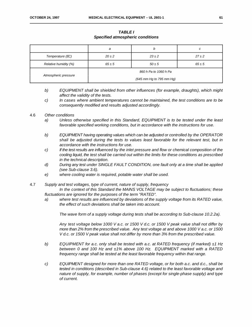
OCTOBER 24, 1997 MEDICAL ELECTRICAL EQUIPMENT – UL 2601-1 61
TABLE ISpecified atmospheric conditions
a b c
Temperature (EC) 20 ± 2 23 ± 2 27 ± 2
Relative humidity (%) 65 ± 5 50 ± 5 65 ± 5
Atmospheric pressure860 h Pa to 1060 h Pa
(645 mm Hg to 795 mm Hg)
b) EQUIPMENT shall be shielded from other influences (for example, draughts), which mightaffect the validity of the tests.
c) In cases where ambient temperatures cannot be maintained, the test conditions are to beconsequently modified and results adjusted accordingly.
4.6 Other conditionsa) Unless otherwise specified in this Standard, EQUIPMENT is to be tested under the least
favorable specified working conditions, but in accordance with the instructions for use.
b) EQUIPMENT having operating values which can be adjusted or controlled by the OPERATORshall be adjusted during the tests to values least favorable for the relevant test, but inaccordance with the instructions for use.
c) If the test results are influenced by the inlet pressure and flow or chemical composition of thecooling liquid, the test shall be carried out within the limits for these conditions as prescribedin the technical description.
d) During any test under SINGLE FAULT CONDITION, one fault only at a time shall be applied(see Sub-clause 3.6).
e) where cooling water is required, potable water shall be used.
4.7 Supply and test voltages, type of current, nature of supply, frequencyIn the context of this Standard the MAINS VOLTAGE may be subject to fluctuations; these
fluctuations are ignored for the purposes of the term "RATED".a) where test results are influenced by deviations of the supply voltage from its RATED value,
the effect of such deviations shall be taken into account.
The wave form of a supply voltage during tests shall be according to Sub-clause 10.2.2a).
Any test voltage below 1000 V a.c. or 1500 V d.c. or 1500 V peak value shall not differ bymore than 2% from the prescribed value. Any test voltage at and above 1000 V a.c. or 1500V d.c. or 1500 V peak value shall not differ by more than 3% from the prescribed value.
b) EQUIPMENT for a.c. only shall be tested with a.c. at RATED frequency (if marked) ±1 Hzbetween 0 and 100 Hz and ±1% above 100 Hz. EQUIPMENT marked with a RATEDfrequency range shall be tested at the least favorable frequency within that range.
c) EQUIPMENT designed for more than one RATED voltage, or for both a.c. and d.c., shall betested in conditions (described in Sub-clause 4.6) related to the least favorable voltage andnature of supply, for example, number of phases (except for single-phase supply) and typeof current.

62 MEDICAL ELECTRICAL EQUIPMENT – UL 2601-1 OCTOBER 24, 1997
d) EQUIPMENT for d.c. only shall be tested with d.c.; the possible influence of polarity on theoperation of the EQUIPMENT shall be taken into consideration, according to the instructionsfor use.
e) Unless otherwise specified by this Standard or by a Particular Standard, EQUIPMENT shallbe tested at the least favorable RATED voltage within the relevant range. It may be necessaryto perform some of the tests more than once in order to establish the least favorable voltage.
f) EQUIPMENT for which alternative ACCESSORIES or components specified by themanufacturer are available shall be tested with those ACCESSORIES or components whichgive the least favorable conditions.
g) EQUIPMENT in tended for use with a specified power supply, for example regarding voltages,capacitances, insulation resistances respectively to earth, etc., shall be tested with such aspecified power supply.
h) Measurement of voltage and currents shall be carried out with instruments which do notappreciably affect the magnitude of the values to be measured.
*4.8 PreconditioningBefore testing is started, EQUIPMENT shall be kept in the testing location unoperated for at
least 24 h. Before the actual series of tests, it is operated as far as is necessary for the tests atRATED voltage, in accordance with the instructions for use.
4.9 Repairs and modificationsIn the event of the necessity for repairs or modifications after a failure or a likelihood of future
failure during the sequence of tests, the testing laboratory and the supplier may agree either upon thepresentation of a new sample on which all tests shall be carried out again or preferably, upon makingall the necessary repairs or modifications after which only relevant tests shall be repeated.
*4.10 Humidity preconditioning treatmentPrior to the tests of Sub-clauses 19.4 and 20.4, EQUIPMENT without special protection
(ordinary EQUIPMENT), DRIP-PROOF and SPLASH-PROOF EQUIPMENT or EQUIPMENT partsshall be subjected to a humidity preconditioning treatment.
EQUIPMENT or EQUIPMENT parts shall be set up complete (or where necessary in parts).Covers used during transport and storage shall be detached.
This test shall be applied only to those EQUIPMENT parts likely to be influenced by theclimatic conditions that are simulated by the test.
Parts which can be detached without the use of a TOOL shall be detached but shall be treatedsimultaneously with the major part.
Doors, drawers and ACCESS COVERS which can be opened or detached without the useof a TOOL shall be opened and detached.
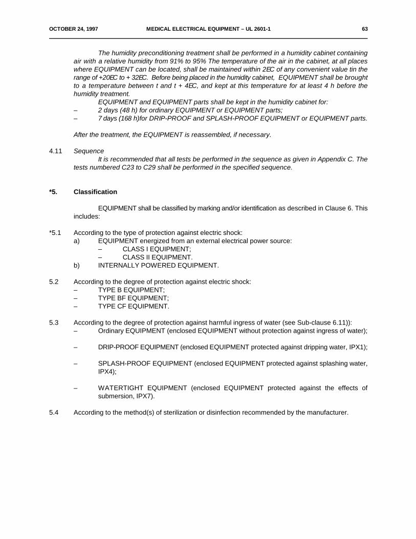
OCTOBER 24, 1997 MEDICAL ELECTRICAL EQUIPMENT – UL 2601-1 63
The humidity preconditioning treatment shall be performed in a humidity cabinet containingair with a relative humidity from 91% to 95% The temperature of the air in the cabinet, at all placeswhere EQUIPMENT can be located, shall be maintained within 2EC of any convenient value tin therange of +20EC to + 32EC. Before being placed in the humidity cabinet, EQUIPMENT shall be broughtto a temperature between t and t + 4EC, and kept at this temperature for at least 4 h before thehumidity treatment.
EQUIPMENT and EQUIPMENT parts shall be kept in the humidity cabinet for:– 2 days (48 h) for ordinary EQUIPMENT or EQUIPMENT parts;– 7 days (168 h)for DRIP-PROOF and SPLASH-PROOF EQUIPMENT or EQUIPMENT parts.
After the treatment, the EQUIPMENT is reassembled, if necessary.
4.11 SequenceIt is recommended that all tests be performed in the sequence as given in Appendix C. The
tests numbered C23 to C29 shall be performed in the specified sequence.
*5. Classification
EQUIPMENT shall be classified by marking and/or identification as described in Clause 6. Thisincludes:
*5.1 According to the type of protection against electric shock:a) EQUIPMENT energized from an external electrical power source:
– CLASS I EQUIPMENT;– CLASS II EQUIPMENT.
b) INTERNALLY POWERED EQUIPMENT.
5.2 According to the degree of protection against electric shock:– TYPE B EQUIPMENT;– TYPE BF EQUIPMENT;– TYPE CF EQUIPMENT.
5.3 According to the degree of protection against harmful ingress of water (see Sub-clause 6.11)):– Ordinary EQUIPMENT (enclosed EQUIPMENT without protection against ingress of water);
– DRIP-PROOF EQUIPMENT (enclosed EQUIPMENT protected against dripping water, IPX1);
– SPLASH-PROOF EQUIPMENT (enclosed EQUIPMENT protected against splashing water,IPX4);
– WATERTIGHT EQUIPMENT (enclosed EQUIPMENT protected against the effects ofsubmersion, IPX7).
5.4 According to the method(s) of sterilization or disinfection recommended by the manufacturer.
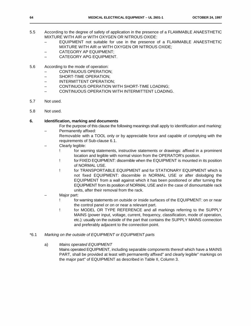
64 MEDICAL ELECTRICAL EQUIPMENT – UL 2601-1 OCTOBER 24, 1997
5.5 According to the degree of safety of application in the presence of a FLAMMABLE ANAESTHETICMIXTURE WITH AIR or WITH OXYGEN OR NITROUS OXIDE:– EQUIPMENT not suitable for use in the presence of a FLAMMABLE ANAESTHETIC
MIXTURE WITH AIR or WITH OXYGEN OR NITROUS OXIDE;– CATEGORY AP EQUIPMENT;– CATEGORY APG EQUIPMENT.
5.6 According to the mode of operation:– CONTINUOUS OPERATION;– SHORT-TIME OPERATION;– INTERMITTENT OPERATION;– CONTINUOUS OPERATION WITH SHORT-TIME LOADING;– CONTINUOUS OPERATION WITH INTERMITTENT LOADING.
5.7 Not used.
5.8 Not used.
6. Identification, marking and documentsFor the purpose of this clause the following meanings shall apply to identification and marking:
– Permanently affixed:Removable with a TOOL only or by appreciable force and capable of complying with therequirements of Sub-clause 6.1.
– Clearly legible:! for warning statements, instructive statements or drawings: affixed in a prominent
location and legible with normal vision from the OPERATOR's position.! for FIXED EQUIPMENT: discernible when the EQUIPMENT is mounted in its position
of NORMAL USE.! for TRANSPORTABLE EQUIPMENT and for STATIONARY EQUIPMENT which is
not fixed EQUIPMENT: discernible in NORMAL USE or after dislodging theEQUIPMENT from a wall against which it has been positioned or after turning theEQUIPMENT from its position of NORMAL USE and in the case of dismountable rackunits, after their removal from the rack.
– Major part:! for warning statements on outside or inside surfaces of the EQUIPMENT: on or near
the control panel or on or near a relevant part.! for MODEL OR TYPE REFERENCE and all markings referring to the SUPPLY
MAINS (power input, voltage, current, frequency, classification, mode of operation,etc.): usually on the outside of the part that contains the SUPPLY MAINS connectionand preferably adjacent to the connection point.
*6.1 Marking on the outside of EQUIPMENT or EQUIPMENT parts
a) Mains operated EQUIPMENTMains operated EQUIPMENT, including separable components thereof which have a MAINSPART, shall be provided at least with permanently affixed" and clearly legible" markings onthe major part" of EQUIPMENT as described in Table II, Column 3.
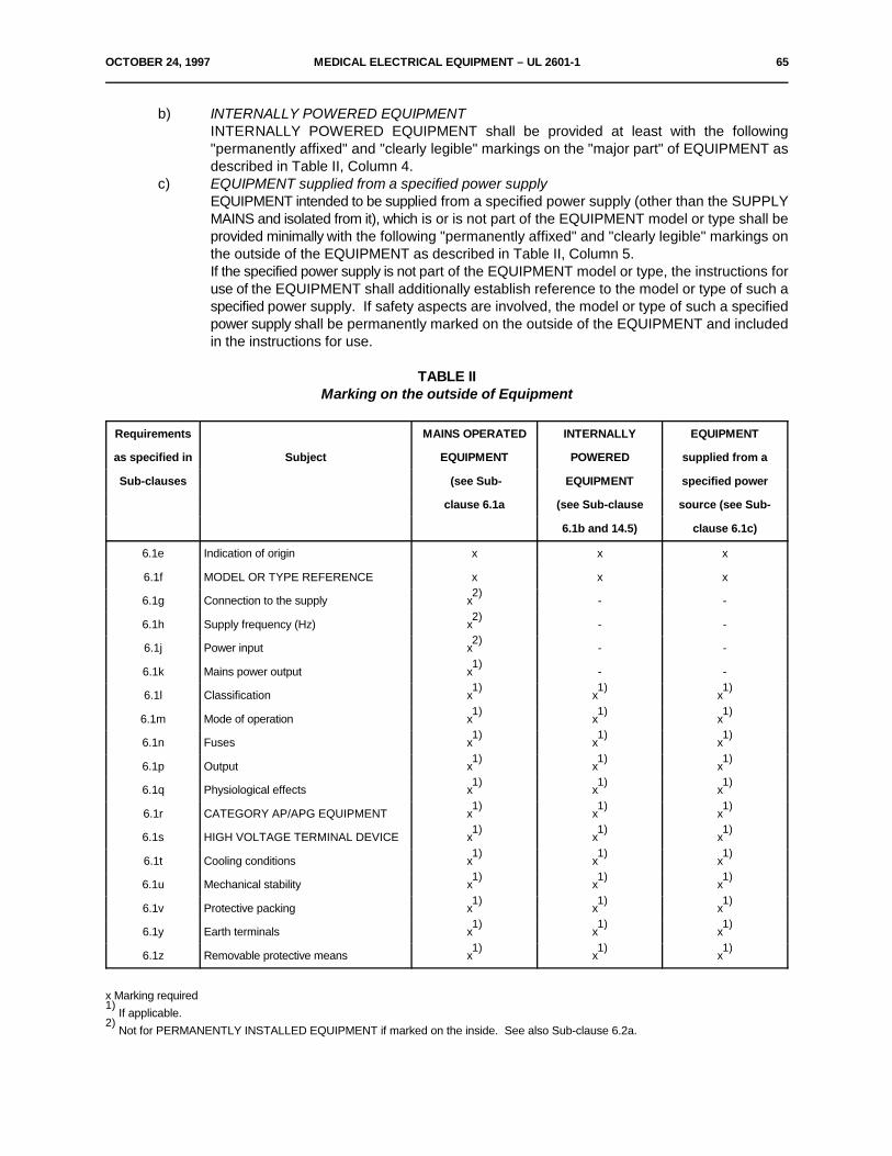
OCTOBER 24, 1997 MEDICAL ELECTRICAL EQUIPMENT – UL 2601-1 65
b) INTERNALLY POWERED EQUIPMENTINTERNALLY POWERED EQUIPMENT shall be provided at least with the following"permanently affixed" and "clearly legible" markings on the "major part" of EQUIPMENT asdescribed in Table II, Column 4.
c) EQUIPMENT supplied from a specified power supplyEQUIPMENT intended to be supplied from a specified power supply (other than the SUPPLYMAINS and isolated from it), which is or is not part of the EQUIPMENT model or type shall beprovided minimally with the following "permanently affixed" and "clearly legible" markings onthe outside of the EQUIPMENT as described in Table II, Column 5.If the specified power supply is not part of the EQUIPMENT model or type, the instructions foruse of the EQUIPMENT shall additionally establish reference to the model or type of such aspecified power supply. If safety aspects are involved, the model or type of such a specifiedpower supply shall be permanently marked on the outside of the EQUIPMENT and includedin the instructions for use.
TABLE IIMarking on the outside of Equipment
Requirements MAINS OPERATED INTERNALLY EQUIPMENT
as specified in Subject EQUIPMENT POWERED supplied from a
Sub-clauses (see Sub- EQUIPMENT specified power
clause 6.1a (see Sub-clause source (see Sub-
6.1b and 14.5) clause 6.1c)
6.1e Indication of origin x x x
6.1f MODEL OR TYPE REFERENCE x x x
6.1g Connection to the supply x - -2)
6.1h Supply frequency (Hz) x - -2)
6.1j Power input x - -2)
6.1k Mains power output x - -1)
6.1l Classification x x x1) 1) 1)
6.1m Mode of operation x x x1) 1) 1)
6.1n Fuses x x x1) 1) 1)
6.1p Output x x x1) 1) 1)
6.1q Physiological effects x x x1) 1) 1)
6.1r CATEGORY AP/APG EQUIPMENT x x x1) 1) 1)
6.1s HIGH VOLTAGE TERMINAL DEVICE x x x1) 1) 1)
6.1t Cooling conditions x x x1) 1) 1)
6.1u Mechanical stability x x x1) 1) 1)
6.1v Protective packing x x x1) 1) 1)
6.1y Earth terminals x x x1) 1) 1)
6.1z Removable protective means x x x1) 1) 1)
x Marking required If applicable.
1)
Not for PERMANENTLY INSTALLED EQUIPMENT if marked on the inside. See also Sub-clause 6.2a.2)
66 MEDICAL ELECTRICAL EQUIPMENT – UL 2601-1 OCTOBER 24, 1997
d) Minimum requirements for marking on EQUIPMENT and on interchangeable partsIf the size of the EQUIPMENT specified in Sub-clause 6.1 or the nature of its ENCLOSUREdoes not allow affixation of all specified markings, then at least the markings as indicated inSub-clauses 6.1 e), 6.1J and 6.1g (not for PERMANENTLY INSTALLED EQUIPMENT), 6.11)and 6.1q (if applicable) shall be affixed and the remaining markings shall be recorded in fullin the ACCOMPANYING DOCUMENTS. Where no marking is practicable, all informationshall be included in the ACCOMPANYING DOCUMENTS.
e) Indication of originThe name and/or trade-mark of the manufacturer or supplier claiming that the EQUIPMENTcomplies with this Standard.
*f) MODEL OR TYPE REFERENCEg) Connection to the supply
– The RATED supply voltage(s) or voltage range(s) to which EQUIPMENT may be connected.
– Nature of supply, for example, number of phases (except for single-phase supply) and type of current.
h) Supply frequencyRATED frequency or RATED frequency range in hertz.
j) Power input (see Clause 7)The RATED input shall be given in amperes or volt-amperes or in watts where the powerfactor exceeds 0.9.In the case of EQUIPMENT for one or several RATED voltage ranges, the RATED input shallalways be given for the upper and lower limits of the range or ranges, if the range(s) is/aregreater than ± 10% of the mean value of the given range.
In the case of range limits which do not differ by more than 10% from the mean value, markingof the input at the mean value of the range is sufficient.If the rating of EQUIPMENT includes both long-time and momentary current or voltampereratings, the marking shall include both long-time and the most relevant momentary volt-ampere rating, each plainly identified and indicated in the ACCOMPANYING DOCUMENTS.
The marked input of EQUIPMENT provided with means for the connection of supplyconductors of other EQUIPMENT shall include the RATED (and marked) output of suchmeans.
k) Mains power outputAUXILIARY MAINS SOCKET OUTLET(S) of EQUIPMENT shall be marked with the maximumallowed output.
l) Classification– The symbol for CLASS II EQUIPMENT, if relevant (see Appendix D, Table DI, Symbol
10).– A symbol, using the letters 1P, followed by X and the relevant characteristic numeral
(1, 4 or 7) of IEC Publication 529, according to the degree of protection provided bythe ENCLOSURE with respect to harmful ingress of water (see Appendix D, Table DI,Symbols 11, 12 or 13).
– A symbol indicating the type of EQUIPMENT according to the degree of protectionagainst electric shock for TYPE B, TYPE BF and TYPE CF EQUIPMENT (see Sub-clause 14.6 and Appendix D, Table DII, Symbols 1, 2 and 3).
If EQUIPMENT has more than one APPLIED PART with different degrees of protection, therelevant symbols shall be clearly marked on such APPLIED PARTS or on or near relevantoutlets (connection points).
OCTOBER 24, 1997 MEDICAL ELECTRICAL EQUIPMENT – UL 2601-1 67
m) Mode of operationIf no marking is provided, EQUIPMENT is assumed to be suitable for CONTINUOUSOPERATION.
n) FusesThe type and rating of fuses accessible from the outside of EQUIPMENT shall be markedadjacent to the fuse-holder.
p) Output– RATED output voltage and current or power (where applicable).– Output frequency (where applicable).
q) Physiological effects (symbols and warning statements)EQUIPMENT producing physiological effects which may cause danger to the PATIENT and/orOPERATOR shall bear a suitable symbol concerning the relevant hazard. The symbol shallappear in a prominent location so that it will be clearly visible after the EQUIPMENT has beeninstalled.If applicable, symbols for particular hazards, as adopted by 150 or IEC Publication 417, shallbe used. For non-ionizing radiation (for example, high-power microwaves), Symbol 8 of TableDII of Appendix D shall be used.
For other hazards, where no specific symbol is available, Symbol 14 of Table DI of AppendixD shall be used.
r) CATEGORY AP/APG EQUIPMENTFor requirements on marking, see Clause 38.
s) HIGH VOLTAGE TERMINAL DEVICESHIGH VOLTAGE TERMINAL DEVICES on the outside of EQUIPMENT which are accessiblewithout the use of a TOOL shall be marked with the symbol "dangerous voltage" (seeAppendix D, Table DII, Symbol 6).
t) Cooling conditionsRequirements for cooling provisions for EQUIPMENT (for example, supply of water or air)shall be marked.
u) Mechanical stabilityFor requirements on EQUIPMENT with a limited stability, see Clause 24.
v) Protective packingIf special measures have to be taken during transport or storage, the packing shall be markedaccordingly (see Sub-clauses 6.8.3d and 10.1 and 150 Publication R780).
Where premature unpacking of EQUIPMENT or EQUIPMENT parts may result in a SAFETYHAZARD, the packing shall be appropriately marked.
w) Not used.x) Not used.y) Earth terminals
– A terminal for the connection of a POTENTIAL EQUALIZATION CONDUCTOR shallbe marked with Symbol 9 of Table DI of Appendix D (see Sub-clause 18e).
– A FUNCTIONAL EARTH TERMINAL shall be marked with Symbol 7 of Table DI ofAppendix D.
68 MEDICAL ELECTRICAL EQUIPMENT – UL 2601-1 OCTOBER 24, 1997
*z) Removable protective meansIf EQUIPMENT has alternative applications which require the removal of a protective meansto utilize a particular function, the protective means shall be marked to indicate the necessityfor replacement when the relevant function is no longer needed. No marking is required whenan interlock is provided (see also Sub-clause 6.8).
Compliance with the requirements of Sub-clause 6.1 is checked as follows:– Inspect the presence of required markings on the outside of EQUIPMENT.– Test the durability of markings.
For determination of durability, markings are rubbed by hand, without undue pressure, first for15 s with a cloth rag soaked with distilled water, then for 15 s with a cloth rag soaked with methylatedspirit at ambient temperature and then for 15 s with a cloth rag soaked with isopropyl alcohol.
Markings shall be clearly legible after all the tests of this Standard have been performed (seeAppendix C, Item C36). Adhesive labels shall not have worked loose or become curled at the edges.When evaluating durability, the effect of NORMAL USE on markings is also to be taken into account.
6.2 Marking on the inside of EQUIPMENT or EQUIPMENT partsa) Marking on the inside of EQUIPMENT or EQUIPMENT parts shall be "clearly legible" as
defined in Sub-clause 6.1. Concerning permanent affixation, it shall not be subjected to therubbing test of Sub-clause 6.1z.The NOMINAL supply voltage or voltage range to which PERMANENTLY INSTALLEDEQUIPMENT can be connected may be marked on the inside or the outside of EQUIPMENT,preferably adjacent to the supply connection terminals.
b) The maximum power loading of heating elements or lampholders designed for use withheating lamps shall be clearly and indelibly marked near the heater or in the heater itself.
c) The presence of HIGH VOLTAGE parts shall be marked with the symbol "dangerous voltage"(see Appendix D, Table DII, Symbol 6).
d) The type of battery and the mode of insertion (if applicable) shall be marked (see Sub-clause56.7b).
e) Fuses accessible only with the aid of a TOOL shall be identified either by type and rating nextto the fuse, or by at least a reference, for example, the diagram number which can beassociated with the technical description in which the type and rating shall be stated.
f) PROTECTIVE EARTH TERMINALS shall be marked with the prescribed symbol (seeAppendix D, Table DI, Symbol 6) unless the PROTECTIVE EARTH TERMINAL is in anAPPLIANCE INLET according to IEC Publication 320.
g) FUNCTIONAL EARTH TERMINALS shall be marked with the prescribed symbol (seeAppendix D, Table DI, Symbol 7).
h) Terminals which are provided exclusively for the connection of the neutral supply conductorin PERMANENTLY INSTALLED EQUIPMENT shall be marked with the prescribed symbol(see Appendix D, Table DI, Symbol 8).
j) Markings required in Sub-clauses 6.2f, h, k and l on or near electrical connection points shallnot be affixed to parts which have to be removed to make the connection. They shall remainvisible after the connection has been made.
OCTOBER 24, 1997 MEDICAL ELECTRICAL EQUIPMENT – UL 2601-1 69
Markings on or near terminals shall comply with IEC Publication 445.
k) The correct method of connection of the supply conductors shall be marked clearly withterminal marking which should be affixed adjacent to the terminals, unless no SAFETYHAZARD can develop if connections are interchanged.If EQUIPMENT is so small that the terminal marking cannot be affixed, it may be included inthe ACCOMPANYING DOCUMENTS. If marking for connection to a three-phase supply isnecessary, it shall be according to IEC Publication 445.
l) If any point within a terminal box or wiring compartment intended for connection of the powersupply conductors for permanently connected EQUIPMENT (including such conductorsthemselves), attains a temperature of more than 75EC during the normal temperature test,EQUIPMENT shall be marked with the following or any equivalent statement:
"For supply connections, use wiring materials suitable for at least ... EC".
This statement shall be located at or near the point where the supply connections are to bemade and shall be clearly discernible after the connections have been made.
m) Not used.
n) Capacitors and/or the connected circuit parts shall be marked as required in Sub-clause 15c.
Compliance with the requirements of Sub-clause 6.2 is checked by application of thetests and criteria as described in Sub-clause 6.1, except the rubbing test.
6.3 Marking of controls and instrumentsa) A mains switch shall be clearly identified. ON and OFF positions shall be marked according
to the relevant symbols of Appendix D (Symbols 15 and 16 of Table DI), or indicated by anadjacent indicator light or other unambiguous means.
b) Different positions of control devices and different positions of switches on EQUIPMENT shallbe indicated by figures, letters or other visual means, e.g. by means of Symbols 17 and 18 ofTable DI.
c) If in NORMAL USE the change of setting of a control could cause a SAFETY HAZARD to thePATIENT, such controls shall be provided with either:– an associated indicating device, e.g. instruments or scale, or– an indication of the direction in which the magnitude of the function changes. See
also Sub-clause 56.10c.d) Not used.e) Not used.f) Controls and indicators with safety functions, e.g. alarms, shall be identified.
Compliance with the requirements of Sub-clause 6.3 is checked by inspection.
70 MEDICAL ELECTRICAL EQUIPMENT – UL 2601-1 OCTOBER 24, 1997
6.4 Symbolsa) Symbols used for marking according to Sub-clauses 6.1 to 6.3 shall conform to Appendix D,
where applicable. See also Sub-clause 6.1q.b) Symbols used for controls and performance shall conform to IEC Publication 878, where
applicable.
Compliance is checked by inspection.
6.5 Colours of the insulation of conductorsa) A PROTECTIVE EARTH CONDUCTOR shall be identified throughout its length by green and
yellow colored insulation.b) Any insulation on conductors inside EQUIPMENT which connect ACCESSIBLE METAL
PARTS or other PROTECTIVELY EARTHED parts with a protective function to thePROTECTIVE EARTH TERMINAL shall be identified by the colors green and yellow at leastat the termination of the conductors.
c) Identification by green and yellow insulation shall only be used for:– PROTECTIVE EARTH CONDUCTORS (see Sub-clause 18b);– Conductors as specified in Sub-clause 6.5b;– POTENTIAL EQUALIZATION CONDUCTORS (see Sub-clause 18e);– Functional earth conductors as specified in Sub-clause 18k.
d) Conductors in POWER SUPPLY CORDS intended to be connected to the neutral conductorof the supply system shall be colored "light blue" as specified in IEC Publication 227(Amendment No. 1) or in IEC Publication 245.
e) Colors of conductors in POWER SUPPLY CORDS shall be in accordance with IEC Publication227 (Amendment No. 1) or with IEC Publication 245.
f) Where a multi-conductor cord is used between EQUIPMENT parts and the maximum allowedresistance of the protective earth connection would be exceeded if only the green and yellowcolored conductor were used, other conductors of the same cord may be connected inparallel with the green and yellow conductor, provided that the ends of such additionalconductors are marked green and yellow.Compliance with the requirements of Sub-clause 6.5 is checked by inspection.
6.6 Identification of medical gas cylinders and connectionsa) Identification of the content of gas cylinders used in medical practice as a part of electrical
EQUIPMENT shall be in accordance with ISO Recommendation ISO/R 32. See also Sub-clause 56.3a.
b) The point of connection of gas cylinders shall be so identified on EQUIPMENT that errors areavoided when a replacement is made.Compliance with the requirements of Sub-clause 6.6 is checked by inspection of the
identification of the content, and the point of connection of gas cylinders.
*6.7 Indicator lights and push-buttonsa) Colors of indicator lights
On EQUIPMENT the color red shall be used exclusively to indicate a warning of danger and/ora need for urgent action.Dot-matrix and other alphanumeric displays are not considered to be indicator lights.

OCTOBER 24, 1997 MEDICAL ELECTRICAL EQUIPMENT – UL 2601-1 71
TABLE IIIRecommended colors of indicator lights and their meaning
for EQUIPMENT
Color Meaning
Yellow Caution or attention required
Green Ready for action
Any other color Meaning other than that of red or yellow
b) Colors of unilluminated push-buttonsThe color red shall be used only for the push-button by which a function is interrupted in caseof emergency.
c) Not used.d) Not used.
Compliance with the requirements of Sub-clause 6.7 is checked by inspection (see also Sub-clause 56.8).
6.8 ACCOMPANYING DOCUMENTS
*6.8.1 GeneralEQUIPMENT shall be accompanied by documents containing at least instructions for use, a
technical description and an address to which the USER can refer. The ACCOMPANYINGDOCUMENTS shall be regarded as a component part of EQUIPMENT.
All applicable classifications specified in Clause 5 shall be included in both the instructions foruse and the technical description, if separable.
All markings specified in Sub-clause 6.1 shall be included in full in the ACCOMPANYINGDOCUMENTS if they have not been permanently affixed to EQUIPMENT by the manufacturer. Seealso Sub-clause 6.1d.
Warning statements and the explanation of warning symbols (marked on the EQUIPMENT)shall be provided in the ACCOMPANYING DOCUMENTS.
6.8.2 Instructions for usea) General information
– Instructions for use shall contain all information necessary to operate theEQUIPMENT in accordance with its specification. This shall include explanation ofthe function of controls, displays and signals, the sequence of operation, connectionand disconnection of detachable parts and ACCESSORIES, replacement of materialwhich is consumed during operation.
– Instructions for use shall include indications on recognized ACCESSORIES,detachable parts and materials, if the use of other parts or materials can degrademinimum safety.
– Instructions for use shall instruct the USER or OPERATOR in sufficient detailconcerning cleaning, preventive inspection and maintenance to be performed by him,including the frequency of such maintenance.
72 MEDICAL ELECTRICAL EQUIPMENT – UL 2601-1 OCTOBER 24, 1997
Such instructions shall provide information for the safe performance of routinemaintenance.Additionally, instructions for use shall identify the parts on which preventive inspectionand maintenance shall be performed by other persons, including the periods to beapplied, but not necessarily including details about the actual performance of suchmaintenance.
– The meaning of figures, symbols, warning statements and abbreviations onEQUIPMENT shall be explained in the instructions for use.
*b) Responsibility of the manufacturerNot used (see Appendix A).
c) SIGNAL OUTPUT and SIGNAL INPUT PARTSIf a SIGNAL OUTPUT or SIGNAL INPUT PART is intended only for connection to specifiedEQUIPMENT complying with the requirements of this Standard, this shall be stated in theinstructions for use (see Sub-clauses 19.2b) and 19.2c)).
d) Cleaning, disinfection and sterilization of parts in contact with the PATIENTFor EQUIPMENT parts which come into contact with the PATIENT during NORMAL USE,instructions for use shall contain details about cleaning or disinfection or sterilization methodsthat may be used (see also Sub-clause 44.7) or, where necessary, identify suitable sterilizationagents, and list the temperature, pressure, humidity and time limits which such EQUIPMENTparts can tolerate.
e) Mains operated EQUIPMENT with additional power source
Instructions for use of mains operated EQUIPMENT containing an additional power source notautomatically maintained in a fully usable condition shall contain a warning statement referringto the necessity for periodical checking or replacement of such an additional power source.If CLASS I EQUIPMENT is specified for operation connected to a SUPPLY MAINS andalternatively using an INTERNAL ELECTRICAL POWER SOURCE, instructions for use shallcontain a statement saying that where the integrity of the external PROTECTIVE EARTHCONDUCTOR arrangement is in doubt, EQUIPMENT shall be operated from its INTERNALELECTRICAL POWER SOURCE.
f) Removal of primary batteriesInstructions for use of EQUIPMENT containing primary batteries shall contain a warning toremove these batteries if EQUIPMENT is not likely to be used for some time.
g) Rechargeable batteriesInstructions for use of EQUIPMENT containing rechargeable batteries shall containinstructions to ensure safe use and adequate maintenance.
h) EQUIPMENT with a specified power supply or battery chargerInstructions for use shall identify power supplies or battery chargers necessary to ensurecompliance with the requirements of this Standard.
OCTOBER 24, 1997 MEDICAL ELECTRICAL EQUIPMENT – UL 2601-1 73
6.8.3 Technical descriptiona) General
The technical description shall provide all data including those mentioned in Sub-clause 6.1and, additionally, all characteristics (or an indication where they may be found) knowledge ofwhich is essential for safe operation.In addition to details required to be included in instructions for use, the technical descriptionshall state whether particular measures or particular conditions are to be observed forinstalling EQUIPMENT and bringing EQUIPMENT into use.
b) Replacement of fuses and other parts– If the type and rating of fuses utilized in the mains supply circuit external to
PERMANENTLY INSTALLED EQUIPMENT is not apparent from the informationconcerning RATED current and mode of operation of EQUIPMENT, the required typeand rating of fuses shall be indicated in at least the technical description.
– The technical description shall contain instructions for replacement ofinterchangeable and/or detachable parts which are subject to deterioration duringNORMAL USE.
c) Circuit diagrams, component part lists, etc.The technical description shall contain a statement that the supplier will make available onrequest circuit diagrams, component part lists, descriptions, calibration instructions, or otherinformation which will assist the USER's appropriately qualified technical personnel to repairthose parts of EQUIPMENT which are designated by the manufacturer as repairable.
d) Restricted environmental conditions for transport and storageIf EQUIPMENT is not capable of withstanding the conditions specified in Sub-clause 10.1 thetechnical description shall contain a specification of the permissible environmental conditionsfor transport and storage which shall be repeated on the outside of the packaging of theEquipment~ (see Sub-clause 6.1 v)).
6.8.4 Not used.
6.8.5 Not used.
Compliance with the requirements of Sub-clause 6.8 is checked by inspection of theACCOMPANYING DOCUMENTS.
7. Power input
7.1 The steady state current or power input of EQUIPMENT at RATED voltage, steady state operatingtemperature, and at operational settings specified by the manufacturer shall not exceed the markedrating as required by Sub-clause 6.1 j) by more than:a) for EQUIPMENT with a power input mainly caused by electric motor drive(s):
+ 25% for a RATED input power up to and including 100 W or 100 VA;+ 15% for a RATED input power over 100 W or 100 VA;
b) for other EQUIPMENT:+ 15% for a RATED input power up to and including 100 W or 100 VA;+ 10% for a RATED input power over 100 W or 100 VA.
74 MEDICAL ELECTRICAL EQUIPMENT – UL 2601-1 OCTOBER 24, 1997
Compliance with the requirements of Sub-clause 7.1 is checked by inspection and by thefollowing tests:a) EQUIPMENT shall be operated as specified in the instructions for use until the input has
reached a stable value.Current or power input shall be measured and compared with markings or the contents of theACCOMPANYING DOCUMENTS.Measured values shall not exceed the limits required in this clause.
b) For EQUIPMENT marked with one or more RATED voltage ranges the test is made at bothupper and lower limits of the ranges, unless the marking of RATED input is related to themean value of the relevant voltage range, in which case the test is made at a voltage equalto the mean value of that range.
c) The steady state current shall be measured with a true r.m.s. reading instrument, for example,a thermal instrument.Power input, if expressed in voltamperes, shall either be measured with a voltampere meteror be determined as the product of the steady state current (measured as described above)and the supply voltage.
7.2 Not used.
SECTION TWO – ENVIRONMENTAL CONDITIONS
Note – This Section replaces the former Section Two: Safety requirements, of the first edition.
*8. Basic safety categoriesThe content of Clause 8 of the first edition has now been transferred to Appendix A 1.2.
9. Removable protective means
Not used. Replaced by Sub-clause 6.1 z).
10. Environmental conditionsThe former title of this clause "Special environmental conditions" and the corresponding text
are not used.
10.1 Transport and storageUnless otherwise stated by the manufacturer, EQUIPMENT shall be capable, while packed
for transport or storage, of being exposed for a period not exceeding 15 weeks to environmentalconditions not outside the following ranges:a) an ambient temperature range of -40EC to +70EC;b) a relative humidity range of 10% to 100%, including condensation;c) an atmospheric pressure range of 500 Hpa to 1060 hPa.
See also Sub-clause 6.1 v).
10.2 OperationEQUIPMENT shall comply with all the requirements of this Standard when operated in
NORMAL USE under the least favorable combination of the following conditions:
OCTOBER 24, 1997 MEDICAL ELECTRICAL EQUIPMENT – UL 2601-1 75
*10.2.1 Environmenta) An ambient temperature range of + 10EC to +40EC.b) A relative humidity range of 30% to 75%.c) An atmospheric pressure range of 700 hPa to 1060 hPa.d) A temperature of the water at the inlet of water-cooled EQUIPMENT not higher than
25 EC.
*10.2.2 Power supplya) EQUIPMENT shall be suitable for a power supply having:
– a RATED voltage not exceeding:! 250 V for HAND-HELD EQUIPMENT;! 250 V d.c. or single-phase a.c. or 500 V polyphase a.c. for EQUIPMENT with aRATED apparent power input of up to 4 kVA;
! 500 V for all other EQUIPMENT;– a sufficiently low internal impedance (as may be required by a Particular Standard);
– voltage fluctuation not exceeding ± 10% of the NOMINAL voltage except momentaryfluctuations exceeding - 10% and of a duration of less than 1 s, for example thoseoccurring at irregular intervals caused by operation of X-ray generators or similarEQUIPMENT;
– no voltage in excess of the NOMINAL value + 10% between any of the conductors ofthe system or between any of these conductors and earth;
– voltages which are practically sinusoidal and forming a practically symmetrical supplysystem in case of polyphase supply;
An alternating voltage is considered in practice to be sinusoidal if any instantaneousvalue of the wave form concerned differs from the instantaneous value of the idealwave form at the same moment by no more than ±5% of the peak value of the idealwave form, unless stated otherwise;
A polyphase voltage system is considered to be symmetrical if neither the magnitudeof its negative sequence components nor the magnitude of its zero sequencecomponents exceeds 20% of the magnitude of its positive sequence components;
A polyphase supply system is considered to be symmetrical if, when supplied froma symmetrical voltage system, the resulting current system is symmetrical. That is,the magnitude of neither the negative sequence current components nor the zerosequence current components exceeds 5% of the magnitude of the positive sequencecurrent components;
– a frequency of not more than 1 kHz;– a frequency which deviates not more than 1 Hz from the NOMINAL value up to 100
Hz and not more than 1 % from the NOMINAL value from 100 Hz to l kHz;
– the protective measures as described in IEC Publication 364.
b) An INTERNAL ELECTRICAL POWER SOURCE, if replaceable, shall be specified by themanufacturer.
Compliance with the conditions of Clause 10 is checked by application of the tests of this Standard.
76 MEDICAL ELECTRICAL EQUIPMENT – UL 2601-1 OCTOBER 24, 1997
11. Not used.12. Not used. Transferred to Sub-clause 3.6.
SECTION THREE – PROTECTION AGAINST ELECTRIC SHOCK HAZARDS
13. General
EQUIPMENT shall be so designed that the risk of electric shock in NORMAL USE and inSINGLE FAULT CONDITION is obviated as far as practicable.
Compliance is considered to be fulfilled If EQUIPMENT meets the relevant requirements ofthis section.
14. Requirements related to classification
14.1 CLASS I EQUIPMENTIn addition to the information given in Sub-clause 2.2.4, the following applies:
a) CLASS I EQUIPMENT may have parts with DOUBLE INSULATION or REINFORCEDINSULATION or parts operating at SAFETY EXTRA-LOW VOLTAGE or ACCESSIBLEPARTS protected by protective impedance in cases where conductive parts of an electricalcircuit have to be accessible to enable EQUIPMENT to function.
*b) If the isolation of the MAINS PART from ACCESSIBLE METAL PARTS of EQUIPMENTspecified for an external d.c. power source is accomplished by BASIC INSULATION only, aseparate PROTECTIVE EARTH CONDUCTOR shall be provided.
14.2 CLASS II EQUIPMENTIn addition to the information given in Sub-clause 2.2.5, the following applies:
a) CLASS II EQUIPMENT shall be one of the following types:1) insulation-enclosed CLASS II EQUIPMENT:
EQUIPMENT having a durable and substantially continuous ENCLOSURE ofinsulating material which envelops all conductive parts with the exception of smallparts, such as name-plates, screws and rivets, which are isolated from LIVE parts byinsulation at least equivalent to REINFORCED INSULATION. The ENCLOSURE ofinsulation-enclosed CLASS II EQUIPMENT may form a part or the whole of theSUPPLEMENTARY INSULATION;
2) metal-enclosed CLASS II EQUIPMENT:EQUIPMENT having a substantially continuous conductive ENCLOSURE in whichDOUBLE INSULATION is used throughout the MAINS PARTS (except for those partswhere REINFORCED INSULATION is used, because the application of DOUBLEINSULATION is manifestly impracticable);
3) EQUIPMENT which is a combination of types 1) and 2) above.
b) If EQUIPMENT is fitted with a device for changing over from CLASS I to CLASS II protection,all of the following requirements shall be fulfilled:– the change-over device shall clearly indicate the selected Class;– for change-over the use of a TOOL shall be necessary;– the EQUIPMENT shall comply with the whole range of requirements for the Class
selected at any given time;– in the CLASS II position the device shall interrupt the connection of the PROTECTIVE
EARTH CONDUCTOR to EQUIPMENT or change it into a FUNCTIONAL EARTHCONDUCTOR, complying with the requirements of Clause 18.
OCTOBER 24, 1997 MEDICAL ELECTRICAL EQUIPMENT – UL 2601-1 77
c) CLASS II EQUIPMENT may be provided with a FUNCTIONAL EARTH TERMINAL or aFUNCTIONAL EARTH CONDUCTOR. See also Sub-clauses l8 k)and l).
14.3 Not used.
*14.4 CLASS l and CLASS II EQUIPMENTa) In addition to BASIC INSULATION, EQUIPMENT shall be provided with an additional
protection according to the requirements of CLASS I or CLASS II EQUIPMENT (see Figures2 and 3).
b) In EQUIPMENT specified for power supply from an external d.c. power source (for example,for use in ambulances), no SAFETY HAZARD shall develop when a connection with the wrongpolarity is made.
14.5 INTERNALLY POWERED EQUIPMENTa) INTERNALLY POWERED EQUIPMENT having a means of connection to a SUPPLY MAINS,
shall have dual classification (e.g. CLASS I EQUIPMENT, INTERNALLY POWEREDEQUIPMENT).
b) INTERNALLY POWERED EQUIPMENT intended for connection to a SUPPLY MAINS shallcomply with the requirements for CLASS I or CLASS II EQUIPMENT while so connected.
14.6 TYPES B, BF and CF EQUIPMENTa) Not used.b) Not used.c) EQUIPMENT or EQUIPMENT parts intended for DIRECT CARDIAC APPLICATION shall be
of TYPE CF.d) EQUIPMENT intended for DIRECT CARDIAC APPLICATION having one or more APPLIED
PARTS of TYPE CF EQUIPMENT may have one or more additional APPLIED PARTS ofTYPE B or TYPE BF EQUIPMENT which may be applied simultaneously if the requirementsof Sub-clause 6.11) for such EQUIPMENT have been met.
A similar requirement applies to EQUIPMENT with a mixture of TYPE B and TYPE BF APPLIEDPARTS.
14.7 Not used.Compliance with the requirements of Clause 14 is checked by inspection and relevant tests.
15. Limitation of voltage and/or energy
a) Not used.b) EQUIPMENT intended to be connected to the SUPPLY MAINS by means of a plug shall be
so designed that 1 s after disconnection of the plug the voltage between the supply pins of theplug and between either supply pin and the ENCLOSURE does not exceed 60 V.
Compliance is checked by the following test:
EQUIPMENT is operated at RATED voltage or at the upper limit of the RATED voltage range.
EQUIPMENT is disconnected from the SUPPLY MAINS by means of the plug with theEQUIPMENT mains switch in the "On" or " Off" position whichever is least favorable.
78 MEDICAL ELECTRICAL EQUIPMENT – UL 2601-1 OCTOBER 24, 1997
The voltage between the pins of the plug and between either pin and the ENCLOSURE ismeasured 1 s after disconnection with an instrument the internal impedance of which does notaffect the test.
The measured voltages shall not exceed 60 V.The test shall be performed ten times.
The test between lines and ENCLOSURE shall not be performed if interference suppressioncapacitors are used with a capacitance between each line and earth of less than 3000 pF forRATED voltages up to and including 250 V or 5000 pF for RATED voltages up to andincluding 125 V.
The test between lines shall not be performed if interference suppression capacitors less thanor equal to 0.1 uF are connected between them.
c) LIVE parts of capacitors or circuit parts connected to them, which become accessible afterEQUIPMENT has been de-energized and ACCESS COVERS as present in NORMAL USEhave been removed immediately thereafter, shall not have a residual voltage exceeding 60V, or, if this value is exceeded, shall not have a residual energy exceeding 2 mJ.
If automatic discharging is not reasonably possible and ACCESS COVERS can be removedonly with the aid of a TOOL, a device which is included and which permits manual discharging isacceptable. The capacitor(s) and/or the connected circuitry shall then be marked.
Compliance is checked by the following test:
EQUIPMENT is operated at RATED voltage and then de-energized. Any ACCESS COVERSas at present in NORMAL USE are removed as quickly as normally possible. Immediately thereafter,the residual voltage on any accessible capacitors or circuit parts shall be measured and the retainedenergy calculated. If a non-automatic discharging device is specified by the manufacturer, its inclusionand marking shall be ascertained by inspection.
*16. ENCLOSURES and PROTECTIVE COVERS
a) EQUIPMENT shall be so constructed and enclosed that there is adequate protection againstcontact with LIVE parts, and with parts which can become LIVE in the event of failure of BASICINSULATION.
This requirement applies for all positions of EQUIPMENT when it is operated as in NORMALUSE, even after opening of lids and doors and removal of parts without the use of a TOOL oraccording to the instructions for use.
During the insertion or removal of lamps, protection against contact with LIVE parts of thelamp shall be ensured if the replacement of the lamp is possible without the use of a TOOL.
OCTOBER 24, 1997 MEDICAL ELECTRICAL EQUIPMENT – UL 2601-1 79
This requirement shall be applied taking into account that:
1) It does not apply to LIVE parts of electrodes in general in the APPLIED PART ofEQUIPMENT, in so far as they are necessarily connected directly or indirectly to thebody of the PATIENT during NORMAL USE.
2) Varnishing, enamelling, oxidation and similar protective finishes, as well as coveringwith sealing compounds which may replasticize at temperatures to be expectedduring operation (including sterilization), shall not be regarded as enclosuresproviding protection against contact with LIVE parts.
3) Not used.4) Not used.5) Where the occurrence of a CONDUCTIVE CONNECTION, either directly or through
the body of the OPERATOR, between a part accessible without the use of a TOOLand a PATIENT is impossible in NORMAL USE, such a part may assume, in case ofa fault in its BASIC INSULATION, a voltage to earth not exceeding 25 V a.c. or 60 V.d.c.
Instructions for use shall instruct the OPERATOR not to touch such a part and thePATIENT simultaneously.
Compliance with the requirements of Sub-clause 16a) is checked by inspection and by a testwith the standard test finger shown in Figure 7, applied in a bent or straight position. Inaddition openings in EQUIPMENT, other than those giving access to LIVE parts in plugs,connectors and socket outlets, are tested with the test pin shown in Figure 8.
The standard test finger and the test pin are applied without appreciable force in everypossible position , except that EQUIPMENT intended to be used on the floor and having amass in any operational condition exceeding 40 kg shall not be tilted. EQUIPMENT which,according to the technical description, is in tended for mounting into a cabinet, shall be testedin its final mounting position.
Openings preventing the entry of the standard test finger of Figure 7 shall be mechanicallytested by means of a straight unjointed test finger of the same dimensions, which shall beapplied with a force of 30 N. If this finger enters, the test with the standard test finger of Figure7 shall be repeated, the finger being pushed through the opening if necessary.
It shall not be possible to touch with the standard test finger or the test pin BASICINSULATION, bare LIVE parts or LIVE parts protected only by lacquer, enamel, ordinarypaper, cotton, oxide film , beads or sealing compound, or parts not PROTECTIVELYEARTHED and separated from the MAINS PART by BASIC INSULATION only.
For signalling contact with LIVE parts, the use of a lamp and a test voltage of at least 40 V isrecommended.
EQUIPMENT openings shall be mechanically tested by means of the test-hook (see Figure9), if the hook can be inserted.
The test-hook is inserted in all openings in question and is subsequently pulled with a forceof 20 N for 10 s and in a direction substantially perpendicular to the surface in which therelevant opening in present. No LIVE parts shall become accessible and the CREEPAGEDISTANCE and AIR CLEARANCES of LIVE parts shall not be reduced below the values asspecified in Sub-clause 57.10.
Compliance is checked using the standard test finger and by inspection.
80 MEDICAL ELECTRICAL EQUIPMENT – UL 2601-1 OCTOBER 24, 1997
b) Any opening in a top cover of an ENCLOSURE shall be so positioned or dimensioned thataccessibility of LIVE parts by means of a freely and vertically suspended test rod with adiameter of 4 mm and a length of 100 mm, penetrating up to its length, is prevented.
Compliance is checked in NORMAL USE by inserting through the holes a metal test rod witha diameter of 4 mm and a length of 100 mm. The test rod is suspended freely and vertically,the penetration being limited to its length. The test rod shall not become LIVE and shall nottouch BASIC INSULATION or any parts not PROTECTIVELY EARTHED and separated fromthe MAINS PART by BASIC INSULATION only.
*c) Conductive parts of actuating mechanisms of electrical controls which are accessible after theremoval of handles, knobs, levers and the like shall either:
– have a resistance of not more than 0.2 S to the PROTECTIVE EARTH TERMINALof the EQUIPMENT when measured with a test voltage of not more than 50 V a.c.open circuit and a test current not less than 1 A, or
– shall be separated from LIVE parts by one of the means described in Sub-clause 17g.
The requirements of this sub-clause do not apply to controls in secondary circuits which areisolated from the MAINS PART by at least BASIC INSULATION and having RATED circuitvoltages not exceeding 25 V a.c. or up to and including 60 V d.c. or peak value. In thesecases shafts and the like may be isolated from parts of the circuit by BASIC INSULATION only.
Compliance is checked by calculation of the resistance from current and voltage drop. It shall notexceed the required value. Alternatively, the presence of adequate separation shall be confirmed byinspection.
*d) Parts within the ENCLOSURE of EQUIPMENT with a circuit voltage exceeding 25 V a.c. or 60V d.c. which cannot be disconnected from the supply by an external mains switch or a plugdevice that is accessible at all times (for example, in circuits for room lighting, remote controlof the main switch etc.) shall be protected against contact even after opening of theENCLOSURE (for example, for the purpose of maintenance) by additional coverings or, in thecase of a spatially separated arrangement, shall be marked clearly as "LIVE".
Compliance is checked by inspection of the required covers or warning notice (if present) and,if necessary, by application of the standard test finger of Figure 7.
e) ENCLOSURES protecting against contact with LIVE parts shall be removable only with the aidof a TOOL or, alternatively, an automatic device shall make these parts not LIVE, when theENCLOSURE is opened or removed.
Excluded are:

OCTOBER 24, 1997 MEDICAL ELECTRICAL EQUIPMENT – UL 2601-1 81
1) ENCLOSURES or EQUIPMENT parts removable without the use of a TOOL andallowing the OPERATOR in NORMAL USE to have access to LIVE parts operatingat a voltage not exceeding 25 V a.c. or 60 V d.c. or peak value supplied from a sourcewhich is separated from the SUPPLY MAINS by one of the methods described in Sub-clauses 17g, 1 to 5.Examples which are applicable are:– covers of illuminated push-buttons;– covers of indicator lamps;– covers over recorder pens;– plug-in modules;– covers of battery compartments.
2) Lampholders allowing access to LIVE parts after removal of the lamp. In such a caseinstructions for use shall instruct the OPERATOR not to touch such a part and thePATIENT simultaneously.
Compliance is checked by inspection and:– by measurement of the effectiveness of an automatic
switching off or discharging device:– by measurement of the voltage of LIVE parts accessible
with the standard test finger of Figure 7.
f) Openings for the adjustment of pre-set controls which may be adjusted by the USER inNORMAL USE by using a TOOL shall be so designed that the TOOL used for adjustment isnot able to touch inside the opening BASIC INSULATION or any LIVE parts or parts notPROTECTIVELY EARTHED and separated from the MAINS PART by BASIC INSULATIONonly.
Compliance is checked by inspection and by insertion through the opening of a metal test rodwith a diameter of 4 mm and a length of 100 mm, in every possible position, in case of doubtwith a force of 10 N. The rod shall not contact BASIC INSULATION or any LIVE parts or partsnot PROTECTIVELY EARTHED and separated from the MAINS PART by BASICINSULATION only.
g) Not used.
*17. Separation (Previous title: Insulation and protective impedances)
a) APPLIED PARTS shall be electrically separated from LIVE parts of EQUIPMENT in NORMALCONDITION and in SINGLE FAULT CONDITION (see Sub-clause 3.6), in such a way thatallowable LEAKAGE CURRENTS (see Clause 19) are not exceeded.
This requirement may be fulfilled by one of the following methods:l) The APPLIED PART is separated from LIVE parts by BASIC INSULATION only, but PROTECTIVELY
EARTHED and the APPLIED PART has such a low internal impedance to earth that LEAKAGE CURRENTSdo not exceed the allowable values in NORMAL CONDITION and SINGLE FAULT CONDITION.
2) The APPLIED PART is separated from LIVE parts by a PROTECTIVELY EARTHED metal part, which maybe a fully enclosing metal screen.
3) The APPLIED PART is not PROTECTIVELY EARTHED but is separated from LIVE parts by an intermediatePROTECTIVELY EARTHED circuit which, in the event of any insulation failure, cannot produce a LEAKAGECURRENT to the APPLIED PART exceeding the allowable value.
4) The APPLIED PART is separated from LIVE parts by DOUBLE or REINFORCED INSULATION.
5) Impedances of components prevent the flow to the APPLIED PART of a PATIENT LEAKAGE CURRENTand PATIENT AUXILIARY CURRENT exceeding the allowable values.

82 MEDICAL ELECTRICAL EQUIPMENT – UL 2601-1 OCTOBER 24, 1997
Compliance with Sub-clause 17a is checked by inspection and measurement.If the CREEPAGE DISTANCE and/or AIR CLEARANCE between the APPLIED PART andLIVE parts does not comply with the requirements of Sub-clause 57.10, such CREEPAGEDISTANCE and/or AIR CLEARANCE shall be short-circuited.The PATIENT LEAKAGE CURRENT and the PATIENT AUXILIARY CURRENT are measuredas described in Sub-clause 19.4 and shall not exceed the limits for NORMAL CONDITIONgiven in Table IV.
If inspection of the APPLIED PART in Item 1) and of the PROTECTIVELY EARTHED metalpart in Item 2) and of the intermediate circuit in Item 3) gives rise to doubts concerning theeffectiveness of the separation under SINGLE FAULT CONDITION, the PATIENT LEAKAGECURRENT and the PATIENT AUXILIARY CURRENT shall be measured after short-circuitingof the insulation between LIVE parts and the APPLIED PART (Item 1 above) or between LIVEparts and the intermediate circuit (Item 3 above).Transient currents occurring during the first 50 ms following the short-circuit shall bedisregarded. After 50 ms, the PATIENT LEAKAGE CURRENT and the PATIENT AUXILIARYCURRENT shall not exceed the allowable value for SINGLE FAULT CONDITION.
Additionally EQUIPMENT and/or its circuits are examined to determine whether the limitationof LEAKAGE CURRENTS and/or PATIENT AUXILIARY CURRENT to the prescribed valuesis dependent on the insulating properties of junctions in semiconductor devices which areinterposed between the APPLIED PART and the MAINS PART; the APPLIED PART and otherLIVE parts and for F-TYPE APPLIED PARTS between the APPLIED PART and earthed parts.
In the event that such semiconductor devices are so identified, they shall be short-circuitedto simulate a break-down of the critical junction, one at a time, to establish that the allowableLEAKAGE CURRENTS and PATIENT AUXILIARY CURRENT for SINGLE FAULTCONDITION are not exceeded.
b) Not used.
c) An APPLIED PART shall have no CONDUCTIVE CONNECTION to ACCESSIBLE METALPARTS which are not PROTECTIVELY EARTHED.Compliance is checked by inspection and the LEAKAGE CURRENT test of Sub-clause 19.4.
d) Hand-held flexible shafts of CLASS I EQUIPMENT shall be isolated from the motor shaft bySUPPLEMENTARY INSULATION.
ACCESSIBLE METAL PARTS driven by an electric motor of CLASS I protection and whichduring NORMAL USE are likely to come into direct contact with an OPERATOR or PATIENT,and which cannot be PROTECTIVELY EARTHED, shall be isolated from the motor shaft byat least SUPPLEMENTARY INSULATION capable of withstanding the dielectric strength testappropriate to the RATED voltage of the motor and having adequate mechanical strength.
Compliance is checked by inspection and test of the insulation between hand-held flexibleshafts and/or driven ACCESSIBLE METAL PARTS of CLASS I EQUIPMENT and the motorshafts. The test specified for SUPPLEMENTARY INSULATION (see Sub-clause 20.4) shallbe applied.
Compliance with the requirements for CREEPAGE DISTANCES and AIR CLEARANCES ischecked additionally (see Sub-clause 57.10).
OCTOBER 24, 1997 MEDICAL ELECTRICAL EQUIPMENT – UL 2601-1 83
e) Not used.
f) Not used.
g) ACCESSIBLE PARTS not being an APPLIED PART shall be electrically separated from LIVEparts of EQUIPMENT in NORMAL CONDITION and in SINGLE FAULT CONDITION (see Sub-clause 3.6) in such a way that allowable LEAKAGE CURRENTS are not exceeded (seeClause 19).
This requirement may be fulfilled by one of the following methods:
1) The ACCESSIBLE PART is separated from LIVE parts by BASIC INSULATION only, but PROTECTIVELYEARTHED.
2) The ACCESSIBLE PART is separated from LIVE parts by a PROTECTIVELY EARTHED metal part, whichmay be a fully enclosing conductive screen.
3) The ACCESSIBLE PART is not PROTECTIVELY EARTHED but is separated from LIVE parts by anintermediate PROTECTIVELY EARTHED circuit which in the event of any insulation failure cannot producean ENCLOSURE LEAKAGE CURRENT exceeding the allowable value.
4) The ACCESSIBLE PART is separated from LIVE parts by DOUBLE or REINFORCED INSULATION.5) Impedances of components prevent the flow to the ACCESSIBLE PART of an ENCLOSURE LEAKAGE
CURRENT exceeding the allowable value.
Compliance is checked by inspection of the required separation in order to find out where aninsulation failure might cause a SAFETY HAZARD.
If the CREEPAGE DISTANCE and/or AIR CLEARANCE between an ACCESSIBLE PART andLIVE parts does not comply with the requirements of Sub-clause 57.10, such CREEPAGEDISTANCE and/or AIR CLEARANCE shall be short-circuited.
The ENCLOSURE LEAKAGE CURRENT shall subsequently be measured as described inSub-clause 19.4 and shall not exceed the limits for NORMAL CONDITION given in Table IV.
If inspection of the PROTECTIVELY EARTHED metal part in Item 2) and of the intermediatecircuit in Item 3) gives rise to doubt concerning the effectiveness of the separation underSINGLE FAULT CONDITION the ENCLOSURE LEAKAGE CURRENT shall be measured byshort circuiting the insulation between LIVE parts and the intermediate circuit.
Transient currents occurring during the first 50 ms following the application of the short-circuitshall be disregarded.
After 50 ms, the ENCLOSURE LEAKAGE CURRENT shall not exceed the allowable value forSINGLE FAULT CONDITION.
Additionally EQUIPMENT and/or its circuits shall be examined to determine if the limitation ofLEAKAGE CURRENTS and/or PATIENT AUXILIARY CURRENTS to the prescribed valuesis dependent on the insulating properties of junctions in semiconductor devices which areinter-posed between the ACCESSIBLE PART and LIVE parts.In the event that such semiconductor devices are so identified, they shall be short-circuitedto simulate a break-down of the critical junction, one at a time, to establish that the allowableLEAKAGE CURRENTS and PATIENT AUXILIARY CURRENTS for SINGLE FAULTCONDITION are not exceeded.

84 MEDICAL ELECTRICAL EQUIPMENT – UL 2601-1 OCTOBER 24, 1997
18. Protective earthing, functional earthing and potential equalization
*a) ACCESSIBLE PARTS of CLASS I EQUIPMENT separated from LIVE parts by BASICINSULATION shall be connected by sufficiently low impedance to the PROTECTIVE EARTHTERMINAL. See also Sub-clause 17 g).Compliance is checked by inspection and the tests of Sub-clauses 18f) and 18g).
b) The PROTECTIVE EARTH TERMINAL shall be suitable for connection to the PROTECTIVEEARTH CONDUCTOR of the power system either by a PROTECTIVE EARTH CONDUCTORin a POWER SUPPLY CORD and, where appropriate, by a suitable plug, or by a fixed andpermanently installed PROTECTIVE EARTH CONDUCTOR. For constructional requirementsfor the earth connection see Clause 58.Compliance is checked by inspection (see Sub-clause 18f)).
c) Not used.d) Not used.
e) If EQUIPMENT is provided with a means for the connection of a POTENTIAL EQUALIZATIONCONDUCTOR this connection shall comply with the following requirements:– be readily accessible;– accidental disconnection is prevented in NORMAL USE;– the conductor can be detached without the use of a TOOL;– the POWER SUPPLY CORD shall not incorporate a POTENTIAL EQUALIZATION
CONDUCTOR;– the connection means shall be marked with Symbol 9, Table DI.
Compliance is checked by inspection.
f) For EQUIPMENT without a POWER SUPPLY CORD the impedance between thePROTECTIVE EARTH TERMINAL and any ACCESSIBLE METAL PART which isPROTECTIVELY EARTHED shall not exceed 0.1 S.For EQUIPMENT with an APPLIANCE INLET the impedance between the protective contactin the APPLIANCE INLET and any ACCESSIBLE METAL PART which is PROTECTIVELYEARTHED shall not exceed 0.1 S.
For EQUIPMENT with a non-detachable POWER SUPPLY CORD the impedance betweenthe protective contact in the MAINS PLUG and any ACCESSIBLE METAL PART which isPROTECTIVELY EARTHED shall not exceed 0.2 S .Compliance is checked by the following test:A current not less than 10A and not exceeding 25 A from current source with a frequency of50 or 60 Hz with a no-load voltage not exceeding 6 V is passed for at least 5 s through thePROTECTIVE EARTH TERMINAL or the protective earth contact in the APPLIANCE INLETor the protective earth pin in the MAINS PLUG and each ACCESSIBLE METAL PART whichcould become LIVE in case of failure in BASIC INSULATION.
The voltage drop between the parts described is measured and the impedance determinedfrom the current and voltage drop. It shall not exceed the values indicated in this sub-clause.
OCTOBER 24, 1997 MEDICAL ELECTRICAL EQUIPMENT – UL 2601-1 85
g) The impedance of protective earth connections other than those described in Sub-clause 18fis allowed to exceed 0.1 S if the continuous fault current to an ACCESSIBLE PART in caseof failure in BASIC INSULATION of such a part or of a component connected to such a partis limited to such an extent that the allowable value of the ENCLOSURE LEAKAGECURRENT in SINGLE FAULT CONDITION is not exceeded.
Compliance is checked by inspection and measurement of the ENCLOSURE LEAKAGECURRENT in a SINGLE FAULT CONDITION. See also Sub-clause 17g.
h) Not used.i) Not used.j) Not used.
k) FUNCTIONAL EARTH TERMINALS shall not be used to provide protective earthing.
Compliance is checked by inspection.
l) If CLASS II EQUIPMENT with isolated internal screens is supplied with a POWER SUPPLYCORD having three conductors, the third conductor (connected to the protective earth contactof the MAINS PLUG) shall be used only as functional earth for these screens and shall becolored green and yellow. The insulation of such internal screens and all internal wiringconnected to them shall be DOUBLE INSULATION or REINFORCED INSULATION.In such case the FUNCTIONAL EARTH TERMINAL of such EQUIPMENT shall be markedso as to distinguish it from a PROTECTIVE EARTH TERMINAL and additionally there shallbe an explanation in the ACCOMPANYING DOCUMENTS.Compliance is checked by inspection and measurement. The insulation shall be tested asdescribed in Clause 20.
19. Continuous LEAKAGE CURRENTS and PATIENT AUXILIARY CURRENTS
19.1 General requirements
a) The electrical insulation providing protection against electric shock shall be of such quality thatcurrents flowing through it are limited to the specified values.
b) The specified values of the continuous EARTH LEAKAGE CURRENT, the ENCLOSURELEAKAGE CURRENT, the PATIENT LEAKAGE CURRENT and the PATIENT AUXILIARYCURRENT apply in any combination of the following conditions:– Both at operating temperature and following the humidity preconditioning treatment,
as described in Sub-clauses 4.10 and 19.4.– In NORMAL CONDITION and in the specified SINGLE FAULT CONDITIONS (see
Sub-clause 19.2).– With EQUIPMENT energized in stand-by condition and fully operating and with any
switch in the MAINS PART in any position.– With the highest RATED supply frequency.– With a supply equal to 110% of the highest RATED MAINS VOLTAGE.
The measured values shall not exceed the allowable values given in Sub clause 19.3.
86 MEDICAL ELECTRICAL EQUIPMENT – UL 2601-1 OCTOBER 24, 1997
c) EQUIPMENT specified for connection to a SELV source can only comply with therequirements of this Standard if such a source complies with this Standard and if heEQUIPMENT, tested in combination with such a source, complies with the requirements forallowable LEAKAGE CURRENTS.Such EQUIPMENT and INTERNALLY POWERED EQUIPMENT shall be investigated forENCLOSURE LEAKAGE CURRENT but only as far as described in Sub-clause 19.4g 3).
*d) The measurement of the ENCLOSURE LEAKAGE CURRENT of CLASS l EQUIPMENT shallonly be performed:– to earth from each part, if present, of the ENCLOSURE not PROTECTIVELY
EARTHED;
– between parts, if present, of the ENCLOSURE not PROTECTIVELY EARTHED.e) The PATIENT LEAKAGE CURRENT shall be measured (see Appendix K):
– in TYPE B EQUIPMENT, from all PATIENT connections connected together or withAPPLIED PARTS loaded according to the manufacturer's instructions;
– in TYPE BF EQUIPMENT, from and to all PATIENT connections of a single functionof the APPLIED PART connected together or with APPLIED PARTS loaded accordingto the manufacturer's instructions;
– in TYPE CF EQUIPMENT, from and to every PATIENT connection in turn.
If the manufacturer specifies alternatives for a detachable part of the APPLIED PART (forexample, PATIENT cord and electrodes), the PATIENT LEAKAGE CURRENT measurementsshall be made with the least favorable specified detachable part.
f) The PATIENT AUXILIARY CURRENT shall be measured between any single PATIENTconnection and all other PATIENT connections connected together.
*19.2 SINGLE FAULT CONDITIONS
a) The EARTH LEAKAGE CURRENT, the ENCLOSURE LEAKAGE CURRENT, the PATIENTLEAKAGE CURRENT and the PATIENT AUXILIARY CURRENT shall be measured under thefollowing SINGLE FAULT CONDITIONS:
– the interruption of each supply conductor one at a time;– the interruption of a PROTECTIVE EARTH CONDUCTOR (not applicable in the case
of EARTH LEAKAGE CURRENT). Not to be investigated if a fixed and permanentlyinstalled PROTECTIVE EARTH CONDUCTOR is specified;
– see also Sub-clauses 17a and 17g.
b) Additionally the PATIENT LEAKAGE CURRENT shall be measured under the followingSINGLE FAULT CONDITIONS:– a voltage equal to 110% of the highest RATED MAINS VOLTAGE applied between
earth and any SIGNAL INPUT or SIGNAL OUTPUT PART, not PROTECTIVELYEARTHED.
This requirement shall not apply where:l) the SIGNAL INPUT or SIGNAL OUTPUT PARTS are designated by the manufacturer
for exclusive connection to EQUIPMENT which complies with requirements specifiedin the ACCOMPANYING DOCUMENTS for such EQUIPMENT;
2) for EQUIPMENT of TYPE B, unless inspection of the circuits and physicalarrangement shows a SAFETY HAZARD exists;
OCTOBER 24, 1997 MEDICAL ELECTRICAL EQUIPMENT – UL 2601-1 87
3) for EQUIPMENT of TYPES CF and BF.– A voltage equal to 110% of the highest RATED MAINS VOLTAGE applied between
any F-TYPE APPLIED PART and earth.– A voltage equal to 110% of the highest RATED MAINS VOLTAGE applied between
earth and any ACCESSIBLE METAL PARTS not PROTECTIVELY EARTHED.
This requirement does not apply:1) for EQUIPMENT of TYPE B, unless inspection of the circuits and physical
arrangement shows that a SAFETY HAZARD exists;2) for EQUIPMENT of TYPES CF and BF.
c) Additionally, the ENCLOSURE LEAKAGE CURRENT shall be measured with a voltage equalto 110% of the highest RATED MAINS VOLTAGE, applied between earth and any SIGNALINPUT or SIGNAL OUTPUT PART, not PROTECTIVELY EARTHED.This requirement is not applied where the SIGNAL INPUT or SIGNAL OUTPUT PARTS aredesignated by the manufacturer for exclusive connection to EQUIPMENT which complies withrequirements specified in the ACCOMPANYING DOCUMENTS for such EQUIPMENT.
*19.3 Allowable values
a) The allowable values of the continuous LEAKAGE CURRENTS and PATIENT AUXILIARYCURRENTS are stated in Table IV for d.c. and a.c. and composite wave forms withfrequencies up to and including 1 kHz. Unless stated otherwise values may be d.c. or r.m.s.
b) For frequencies above 1 kHz, the allowable values according to Table IV shall be multipliedby the numerical value of the frequency in kilohertz.However, the results of the multiplication shall not exceed 10 mA. See also Sub-clause19.4e).
c) Not used.d) Not used.e) Not used, but see Notes 3) and 4) of Table IV.

88 MEDICAL ELECTRICAL EQUIPMENT – UL 2601-1 OCTOBER 24, 1997
TABLE IV* Allowable values of continuous LEAKAGE and PATIENT AUXILIARY CURRENTS, in
milliamperes
Current Type B Type BF Type CF
N.C. S.F.C N.C S.F.C N.C. S.F.C
EARTH LEAKAGE CURRENT general 0.5 1 0.5 1 0.5 11) 1) 1)
EARTH LEAKAGE CURRENT FOR EQUIPMENT according to notes and 2.5 5 2.5 5 2.5 52) 4) 1) 1) 1)
EARTH LEAKAGE CURRENT FOR EQUIPMENT according to note 5 10 5 10 5 103) 1) 1) 1)
ENCLOSURE LEAKAGE CURRENT 0.1 0.5 0.1 0.5 0.1 0.5
PATIENT LEAKAGE CURRENT 0.1 0.5 0.1 0.5 0.01 0.05
PATIENT LEAKAGE CURRENT (MAINS VOLTAGE on the SIGNAL INPUT PART - 5 - - - -OR SIGNAL OUTPUT PART)
PATIENT LEAKAGE CURRENT (MAINS VOLTAGE on the APPLIED PART) - - - 5 - 0.05
* PATIENT AUXILIARY CURRENT d.c 0.01 0.05 0.01 0.05 0.01 0.05
a.c 0.1 0.5 0.1 0.5 0.01 0.05
N.C.: NORMAL CONDITIONS.F.C.: SINGLE FAULT CONDITION
Notes on Table IV1) The only SINGLE FAULT-CONDITION for the EARTH LEAKAGE CURRENT Is the interruption of one supply conductor at a time
(see Sub-clause 19.2a) and Figure 16).2) EQUIPMENT which has no PROTECTIVELY EARTHED ACCESSIBLE PARTS and no means for the protective earthing of other
EQUIPMENT and which complies with the requirements for the ENCLOSURE LEAKAGE CURRENT and for the PATIENTLEAKAGE CURRENT (if applicable).Example:Some computers with a screened MAINS PART.
3) EQUIPMENT specified to be permanently installed with a PROTECTIVE EARTH CONDUCTOR which is electrically so connectedthat the connection can only be loosened with the aid of a TOOL and which is so fastened or otherwise so secured mechanicallyat a specific location that it can only be moved after the use of a TOOL.
Examples of such EQUIPMENT are:! Major components of an X-ray installation such as the X-ray generator, the examination or treatment table.
! EQUIPMENT with mineral insulated heaters.! EQUIPMENT with an EARTH LEAKAGE CURRENT higher than stated in Table IV, first line, which is due to
compliance with requirements for radio-interference suppression.
4) MOBILE X-ray EQUIPMENT and MOBILE EQUIPMENT with mineral insulation.
OCTOBER 24, 1997 MEDICAL ELECTRICAL EQUIPMENT – UL 2601-1 89
19.4 Tests*a) General
1) The EARTH LEAKAGE CURRENT, the ENCLOSURE LEAKAGE CURRENT, thePATIENT LEAKAGE CURRENT and the PATIENT AUXILIARY CURRENT aremeasured:
– after the EQUIPMENT has been brought up to operating temperature in accordancewith the requirements of Section Seven, and
– after the humidity preconditioning treatment as described in Sub-clause 4.10.
The measurements shall be carried out with the EQUIPMENT located in an environment witha temperature approximately equal to t where t is the temperature of the humidity cabinet anda relative humidity between 45 % and 65 % and shall commence 1 h after the end of thehumidity preconditioning treatment.
The measurements which do not energize the EQUIPMENT shall be made first.
2) EQUIPMENT is connected to a supply with a voltage equal to 110% of the highestRATED MAINS VOLTAGE.
3) Three-phase EQUIPMENT which is also suitable for single-phase supply is tested assingle-phase EQUIPMENT with the three sections connected in parallel.
4) Where examination of the circuit arrangement and the arrangement of componentsand material of EQUIPMENT shows no possibility of any SAFETY HAZARD, thenumber of tests may be reduced.
5) Not used.
*b) Measuring supply circuits
1) EQUIPMENT specified for connection to a SUPPLY MAINS which is approximatelyat earth potential on one side and EQUIPMENT for which the nature of the powersupply is not specified, is connected to a circuit as shown in Figure 10.
2) EQUIPMENT specified for connection to a SUPPLY MAINS of which the voltagesbetween the lines and the neutral are approximately equal and in opposition, isconnected to a circuit as shown in Figure 11.
3) Polyphase or single-phase EQUIPMENT, specified for connection to a polyphase forexample, three-phase) SUPPLY MAINS, is connected to one of the circuits as shownin Figures 12 and 13.
4) EQUIPMENT SPECIFIED for use with a specified CLASS I single-phase powersupply is connected to a circuit as shown in Figure 14.The switch S shall be opened and closed in turn during the tests.8However, if the specified power supply has a fixed and permanently installedPROTECTIVE EARTH CONDUCTOR, the switch S shall be left closed during tests.8
5) EQUIPMENT specified for use with a specified CLASS II single-phase power supplyis connected to a circuit as shown in Figure 14, not using the protective earthconnection S .8
90 MEDICAL ELECTRICAL EQUIPMENT – UL 2601-1 OCTOBER 24, 1997
c) Connection of the EQUIPMENT to the measuring supply circuit
1) EQUIPMENT provided with a POWER SUPPLY CORD is tested using this cord.
2) EQUIPMENT provided with an APPLIANCE INLET is tested while connected via aDETACHABLE POWER SUPPLY CORD having a length of 3 m or a length and typespecified by the manufacturer.
3) EQUIPMENT specified to be PERMANENTLY INSTALLED is tested while connectedto the measuring supply circuit via the shortest possible connection.
*d) Measuring arrangement
1) It is recommended to position the measuring supply circuit and the measuring circuitas far as possible a way from unscreened power supply leads and (unless specifiedotherwise in the following sub-clauses) to avoid placing the EQUIPMENT on or neara large earthed metal surface.
2) However, external parts of the APPLIED PART, including PATIENT cords (whenpresent), shall be placed on an insulating surface with a dielectric constant ofapproximately 1 (for example, expanded polystyrene) and approximately 200 mmabove an earthed metal surface.
e) Measuring device (MD)
1) The measuring device shall load the source of LEAKAGE CURRENT or PATIENTAUXILIARY CURRENT with a resistive impedance of approximately 1000 S for d.c.and a.c. and for composite wave forms with frequencies up to and including 1 MHz.
2) The evaluation of current or current components according to Sub-clauses 19.3a)and b) is obtained automatically if a measuring device according to Figure 15 or asimilar circuit with the same frequency characteristic is used. This allowsmeasurement of the total effect of all frequencies with a single instrument.
If currents or current components with frequencies exceeding 1 kHz and a valueexceeding 10 mA are likely to occur, these shall be measured by other appropriatemeans.
3) The deviation of the frequency characteristic of Figure 15 from the ideal curvefollowing from the requirement of Sub-clause 19.3b) (at 1 kHz about 3 dB), isdisregarded.
*4) The measuring instrument as shown in Figure 15 shall have an impedance ofapproximately 1 MS or more for frequencies from d.c. up to and including 1 MHz. Itshall indicate the true r.m.s. value of the voltage across the measuring impedancebeing d.c. or a.c. or a composite wave form having components with frequencies fromd.c. up to and including 1 MHz; with an indicating error not exceeding ±5% of theindicated value.
OCTOBER 24, 1997 MEDICAL ELECTRICAL EQUIPMENT – UL 2601-1 91
The scale may indicate the current through the measuring device including automaticevaluation of components with frequencies above 1 kHz so as to enable directcomparison of the reading with Table IV.The requirements for percentage-indicating error and for calibration may be limitedto frequency range with an upper limit lower than 1 MHz if it can be proven (forexample, by the use of an oscilloscope) that frequencies above such an upper limitdo not occur in the measured current.
f) Measurement of the EARTH LEAKAGE CURRENT
1) CLASS I EQUIPMENT, with or without an APPLIED PART, is tested according toFigure 16, using one of the measuring supply circuits of Figures 10, 11, 12 or 13, asrelevant.
2) EQUIPMENT specified for use with a specified CLASS I single-phase power supplyis tested according to Figure 17, using the measuring supply circuit of Figure 14. Ifthe EQUIPMENT is PROTECTIVELY EARTHED, the measurement with MD2 shallalso be performed.
g) Measurement of the ENCLOSURE LEAKAGE CURRENT
1) CLASS I EQUIPMENT, with or without an APPLIED PART, is tested according toFigure 18, using one of the measuring supply circuits of Figures 10, 11, 12 or 13, asrelevant.
Measure with MD1 between earth and each part of the ENCLOSURE which is notPROTECTIVELY EARTHED.Measure with MD2 between parts of the ENCLOSURE which are notPROTECTIVELY EARTHED.
2) CLASS II EQUIPMENT, with or without an APPLIED PART, is tested according toFigure 18 using one of the measuring supply circuits of Figures 10, 11, 12 or 13 asrelevant, but without the protective earth connection and S .7Measure with MD1 between the ENCLOSURE and earth or between each part of theENCLOSURE if more than one is present.Measure with MD2 between parts of the ENCLOSURE or between any twoENCLOSURES if more than one is present.
3) EQUIPMENT specified for connection to an SELV-source and INTERNALLYPOWERED EQUIPMENT are tested for ENCLOSURE LEAKAGE CURRENT flowingbetween different parts of the ENCLOSURE (measuring device applied as MD2 inFigure 18).
4) EQUIPMENT, with or without an APPLIED PART, specified for use with a specifiedCLASS I single-phase power supply is tested according to Figure 19, using themeasuring supply circuit of Figure 14.EQUIPMENT, with or without an APPLIED PART, specified for use with a specifiedCLASS II single-phase power supply shall be tested according to Figure 19 using themeasuring supply circuit of Figure 14, but without the protective earth connection(s)and S8

92 MEDICAL ELECTRICAL EQUIPMENT – UL 2601-1 OCTOBER 24, 1997
The protective earth connection(s) to EQUIPMENT and S are used only when the8EQUIPMENT itself is of CLASS I.
Test a CLASS I power supply and/or CLASS I EQUIPMENT connected to it, asmentioned under "CLASS I EQUIPMENT"- (see Sub-clause 19.4 g) 1)).
Test a CLASS II power supply and EQUIPMENT not being CLASS I, connected to it,as mentioned under - "CLASS II EQUIPMENT" (see Sub-clause 19.4 g) 2)).
5) If EQUIPMENT has an ENCLOSURE or a part of the ENCLOSURE made ofinsulating material, metal foil of maximum 20 cm X 10 cm shall be applied in intimatecontact with the ENCLOSURE or relevant part of the ENCLOSURE.To achieve this, it may be pressed against the insulating material with a pressure ofapproximately 0.5 N/cm .2
The metal foil is shifted, if possible, to determine the highest value of theENCLOSURE LEAKAGE CURRENT. Care shall be taken that the metal foil does nottouch any metal parts of the ENCLOSURE which are possibly PROTECTIVELYEARTHED; however, metal parts of the ENCLOSURE which are not PROTECTIVELYEARTHED may be covered partly or totally by the metal foil.
Where it is intended to measure the ENCLOSURE LEAKAGE CURRENT in SINGLEFAULT CONDITION, the metal foil may be arranged to contact the metal part of theENCLOSURE.
Where the surface of the ENCLOSURE contacted by the PATIENT or OPERATORmay be larger than that of a normal hand, the size of the foil is increasedcorresponding to the area of contact.
6) If applicable, the measurements according to Sub-clause 17g) are performed inaddition to those mentioned above.
*h) Measurement of the PATIENT LEAKAGE CURRENTFor connections to the APPLIED PART(S) see Sub-clause 19.1e) and Appendix K.
1) CLASS I EQUIPMENT with an APPLIED PART is tested according to Figure 20, usingone of the measuring supply circuits of Figures 10, 11, 12 or 13, as relevant.
2) CLASS I EQUIPMENT with an F–TYPE APPLIED PART is additionally testedaccording to Figure 21, using one of the measuring supply circuits of Figures 10, 11,12 or 13, as relevant.
SIGNAL INPUT and SIGNAL OUTPUT PARTS shall, if not already permanentlyearthed in the EQUIPMENT, be connected to earth.The value of the voltage to be set at the transformer T in Figure 21 shall be equal to2110% of the highest RATED MAINS VOLTAGE of the EQUIPMENT.
OCTOBER 24, 1997 MEDICAL ELECTRICAL EQUIPMENT – UL 2601-1 93
3) CLASS I EQUIPMENT with an APPLIED PART and a SIGNAL INPUT and/or SIGNALOUTPUT PART, is, when required (see Sub-clause 19.2b)), additionally testedaccording to Figure 22, using one of the measuring supply circuits of Figures 10,11,12 or 13, as relevant.
The value of the voltage set at the transformer T shall be equal to 110% of the2highest RATED MAINS VOLTAGE of the EQUIPMENT. The SIGNAL INPUT andSIGNAL OUTPUT PART is short-circuited unless a load is prescribed by themanufacturer, in which case the test voltage is applied in turn to all poles of theSIGNAL INPUT and SIGNAL OUTPUT PART.
4) CLASS II EQUIPMENT is tested as CLASS I EQUIPMENT mentioned in tests 1) to3) above, but disregarding the protective earth connection(s) and S .7
The PATIENT LEAKAGE CURRENT of CLASS II EQUIPMENT with an F-TYPEAPPLIED PART and an external voltage on the APPLIED PART is measured with themetal ENCLOSURE (if present) connected to earth.
In the case of CLASS II EQUIPMENT with an ENCLOSURE made of insulatingmaterial, it is placed in any position of NORMAL USE upon a flat metal surfaceconnected to earth with dimensions at least equal to the plan-projection of theENCLOSURE.
5) EQUIPMENT with an APPLIED PART, specified for use with a specified single-phasepower supply is tested using the measuring supply circuit of Figure 14, butdisregarding the protective earth connection(s) and S if the specified single-phase8power supply is of CLASS II.
– If EQUIPMENT itself is of CLASS I, it is tested as CLASS I EQUIPMENT mentionedin test 1) above.
– If EQUIPMENT itself is of CLASS II, it is tested as CLASS II EQUIPMENT mentionedin test 4) above.
– If the specified single-phase power supply is of CLASS I only S shall be opened8(SINGLE FAULT CONDITION) and closed during the measurement, while S S S1 2 3and S (when present) are closed.10
6) INTERNALLY POWERED EQUIPMENT is tested according to Figure 23.Where the ENCLOSURE is made of insulating material, metal foil as described inSub-clause 19.4g) 5) shall be applied.
7) INTERNALLY POWERED EQUIPMENT provided with an F-TYPE APPLIED PARTis additionally tested according to Figure 24. The value of the voltage to be set at thetransformer T shall be 250 V the supply frequency (see Sub-clause 19.1b)).2
For this test a metal ENCLOSURE of EQUIPMENT and the SIGNAL INPUT andSIGNAL OUTPUT PART is connected to earth.An ENCLOSURE made of insulating material is placed in any position of NORMALUSE upon a flat metal surface connected to earth with dimensions at least equal tothe plan-projection of the ENCLOSURE.

94 MEDICAL ELECTRICAL EQUIPMENT – UL 2601-1 OCTOBER 24, 1997
8) INTERNALLY POWERED EQUIPMENT provided with an APPLIED PART and aSIGNAL INPUT and/or SIGNAL OUTPUT PART is, if applicable according to Sub-clause 19.2b), additionally tested according to Figure 25. The value of the voltageto be set at the transformer T shall be 250 V the supply frequency (see Sub-clause119.1 b) ).
For this test EQUIPMENT is positioned as in NORMAL USE as indicated in Sub-clause 19.4 d) or as indicated in Sub-clause 19.4 h) 7), whichever is less favorable.
9) An APPLIED PART consisting of a surface made of insulating material is tested usingmetal foil as mentioned under Sub-clause 19.4g) 5). Alternatively a saline solutionmay be used in which the APPLIED PART is immersed.Where the surface of the APPLIED PART intended to contact the PATIENT isconsiderably larger than that of a foil of 20 cm X 10 cm, the size of the foil isincreased to correspond to the area of contact.
10) If loading of the APPLIED PART is specified by the manufacturer, the measuringdevice is connected in turn to all poles of the load (APPLIED PART).
11) If applicable, the measurements according to Sub-clause 17a) are performed inaddition to those mentioned above.
j) Measurement of the PATIENT AUXILIARY CURRENTFor connections to the APPLIED PART(S) see Sub-clause 19.1e) and Appendix K.
1) CLASS I EQUIPMENT with an APPLIED PART is tested according to Figure 26, usingone of the relevant measuring supply circuits of Figures 10, 11, 12 or 13.
2) CLASS II EQUIPMENT with an APPLIED PART is tested as CLASS I EQUIPMENTmentioned above, but disregarding the protective earth connection(s) and S .7
3) EQUIPMENT with an APPLIED PART, and specified for use with a specified single-phase power supply is tested using the measuring supply circuit of Figure 14, butdisregarding the protective earth connection and S if the specified single-phase8power supply is of CLASS II.
If EQUIPMENT itself is of CLASS I, it is tested as CLASS I EQUIPMENT mentionedunder paragraph 1).
If EQUIPMENT itself is of CLASS II, it is tested as CLASS II EQUIPMENT mentionedunder paragraph 2).
If the specified single-phase power supply is of CLASS I,– S shall be opened (SINGLE FAULT CONDITION) and S S and S shall be closed;8 1 2 3
– Additionally S shall be closed and S , S or S shall be opened in turn (SINGLE8 1 2 3FAULT CONDITION).
During the three measurement procedures described above S and S shall be set in all5 10possible combinations of positions.
4) INTERNALLY POWERED EQUIPMENT is tested according to Figure 27.
OCTOBER 24, 1997 MEDICAL ELECTRICAL EQUIPMENT – UL 2601-1 95
20. Dielectric strength
Only insulation with a safety function need be subject to testing.
20.1 General requirements for all types of EQUIPMENTThe dielectric strength shall be tested (see also Appendix E):
A-a Between LIVE parts and ACCESSIBLE METAL PARTS which are PROTECTIVELY1EARTHED.
This insulation shall be BASIC INSULATION.A-a Between LIVE parts and parts of the ENCLOSURE not PROTECTIVELY EARTHED.2
This insulation shall be DOUBLE INSULATION or REINFORCED INSULATION.A-b Between LIVE parts and conductive parts isolated from the LIVE parts by BASIC
INSULATION forming part of DOUBLE INSULATION.
This insulation shall be BASIC INSULATION.
A-c Between the ENCLOSURE and conductive parts isolated from LIVE parts by BASICINSULATION forming part of DOUBLE INSULATION.
This insulation shall be SUPPLEMENTARY INSULATION.
A-d Not used.
A-e Between LIVE parts not being parts of SIGNAL INPUT PARTS or SIGNAL OUTPUTPARTS and SIGNAL INPUT PARTS or SIGNAL OUTPUT PARTS notPROTECTIVELY EARTHED.
This insulation shall be DOUBLE INSULATION or REINFORCED INSULATION.Separation shall be achieved by one of the methods indicated in Items g) 1 to 5 ofClause 17.
No separate investigation is needed if the voltages appearing on the SIGNAL INPUTPART (SIP) and/or SIGNAL OUTPUT PART (SOP) in NORMAL and SINGLE FAULTCONDITIONS do not exceed SAFETY EXTRA LOW VOLTAGE.
A-f Between parts of opposite polarity of the MAINS PART. This insulation shall beBASIC INSULATION.
The electrical insulation of parts A-f shall be investigated only if, after inspection ofinsulation quantities and sizes, including CREEPAGE DISTANCES and AIRCLEARANCES according to Sub-clause 57.10, no complete compliance can beestablished.
If separation of circuits or protection of components, necessary for the investigationof parts A-f, is not possible without damage to EQUIPMENT, the manufacturer andthe testing laboratory shall make an agreement as to any other method possible tofulfil the purpose of this investigation.

96 MEDICAL ELECTRICAL EQUIPMENT – UL 2601-1 OCTOBER 24, 1997
A-g Between a metal ENCLOSURE (or cover) lined internally with insulating material anda metal foil applied for testing purposes in contact with the interior surface of thelining. Such a lining may be applied where the distance, measured through the lining,between a LIVE PART and the ENCLOSURE (or cover) is less than the AIRCLEARANCE required according to Sub-clause 57.10.
Where the ENCLOSURE (or cover) is PROTECTIVELY EARTHED, the required AIRCLEARANCE is that for BASIC INSULATION and the lining shall be treated as such.
Where the ENCLOSURE (or cover) is not PROTECTIVELY EARTHED, the requiredAIR CLEARANCE is that for REINFORCED INSULATION.
If the distance between the LIVE PART and the interior surface of the lining is not lessthan the AIR CLEARANCE required for BASIC INSULATION, that distance shall betreated as BASIC INSULATION. The lining shall then be treated asSUPPLEMENTARY INSULATION.
Where the distance, as described before, is less than that required for BASICINSULATION, the lining shall be treated as REINFORCED INSULATION.
A-h Not used.
A-j Between ACCESSIBLE PARTS not PROTECTIVELY EARTHED and likely to becomeLIVE in the event of failure of the insulation of the POWER SUPPLY CORD, andeither metal foil wrapped around the POWER SUPPLY CORD inside inlet bushings,cord guards, cord anchorages and the like, or a metal rod having the same diameteras the POWER SUPPLY CORD, inserted in its place.
This insulation shall be SUPPLEMENTARY INSULATION.
A-k Between, in turn, a SIGNAL INPUT PART, A SIGNAL OUTPUT PART andACCESSIBLE PARTS not PROTECTIVELY EARTHED.
This insulation shall be DOUBLE INSULATION or REINFORCED INSULATION.
This insulation need not be investigated separately if at least one of the followingconditions is satisfied:
a) The voltages appearing on the SIGNAL INPUT PART or SIGNAL OUTPUTPART in NORMAL USE do not exceed SAFETY EXTRA LOW VOLTAGE.
b) The LEAKAGE CURRENTS do not exceed the allowable values in SINGLEFAULT CONDITION in the event of any single component failure in theSIGNAL INPUT or SIGNAL OUTPUT PARTS.
c) The SIGNAL INPUT PARTS or SIGNAL OUTPUT PARTS arePROTECTIVELY EARTH ED or separated from ACCESSIBLE PARTS byany of the means as described in Sub-clause 17g.
d) The SIGNAL INPUT or SIGNAL OUTPUT PARTS are designated by themanufacturer for exclusive connection to EQUIPMENT which complies withrequirements specified in the ACCOMPANYING DOCUMENTS for suchEQUIPMENT.

OCTOBER 24, 1997 MEDICAL ELECTRICAL EQUIPMENT – UL 2601-1 97
20.2 Requirements for EQUIPMENT with an APPLIED PART
For EQUIPMENT with an APPLIED PART, the dielectric strength shall also be tested (see alsoAppendix E):B-a Between the APPLIED PART (PATIENT CIRCUIT) and LIVE parts.
This insulation shall be DOUBLE INSULATION or REINFORCED INSULATION.
This insulation need not be investigated separately if the parts in question areeffectively separated as described in Sub-clause 17a 1, 2 or 3). In this case the testis replaced by the tests of B-c and B-d.
Where the total separation between the APPLIED part and the LIVE part consists ofmore than one circuit insulation, possibly of circuits with a substantially differentoperating voltage, care shall be taken that each part of the separation means isstressed with the proper test voltage derived from the relevant reference voltage.This may mean that the test B-a may have to be replaced by two or more tests onseparate parts of the separation means.
B-b Between parts of the APPLIED PART and/or between APPLIED PARTS. SeeParticular Standards.
B-c Between the APPLIED PART and parts not PROTECTIVELY EARTHED which areisolated from LIVE parts by BASIC INSULATION only.
This insulation shall be SUPPLEMENTARY INSULATION.
This insulation need not be investigated separately if the parts in question areeffectively separated as described in Sub-clause 17 a 1, 2 or 3.
B-d Between an F-TYPE APPLIED PART (PATIENT CIRCUIT) and the ENCLOSUREincluding SIGNAL INPUT PARTS and SIGNAL OUTPUT PARTS. See also Sub-clauses 20.3 and 20.4j.
This insulation shall be BASIC INSULATION. See also B-e.
B-e Between an F-TYPE APPLIED PART (PATIENT CIRCUIT) and the ENCLOSUREwhere the F-TYPE APPLIED PART contains voltages stressing the insulation to theENCLOSURE in NORMAL USE including earthing of any part of the APPLIED PART.
This insulation shall be DOUBLE INSULATION or REINFORCED INSULATION.
B-f Not used (see B-a).
*20.3 Values of test voltages
The dielectric strength of the electrical insulation at operating temperature as well as followingthe humidity preconditioning treatment and after any required sterilization procedure, if applicable (seeSub-clause 44.7), shall be sufficient to withstand the test voltages as specified in Table V.
The reference voltage (U) as used in Table V is the voltage to which the relevant insulation issubjected in NORMAL USE and at RATED supply voltage or a voltage as specified by themanufacturer, whichever is the greater.
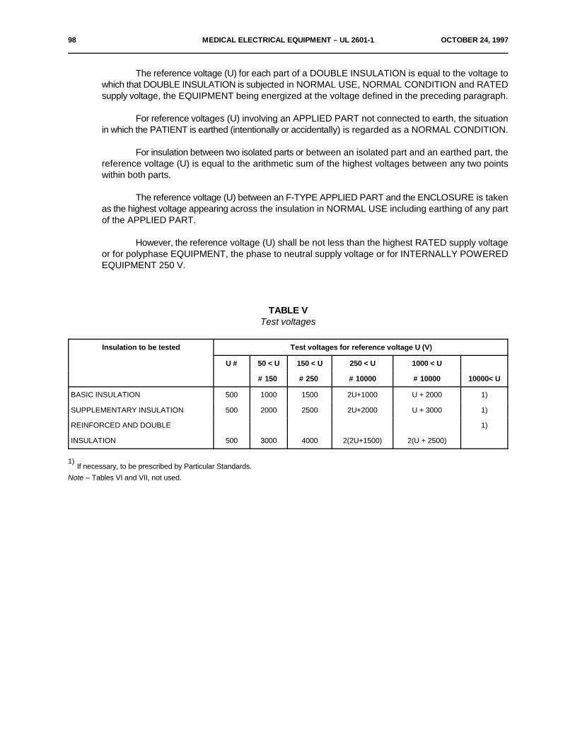
98 MEDICAL ELECTRICAL EQUIPMENT – UL 2601-1 OCTOBER 24, 1997
The reference voltage (U) for each part of a DOUBLE INSULATION is equal to the voltage towhich that DOUBLE INSULATION is subjected in NORMAL USE, NORMAL CONDITION and RATEDsupply voltage, the EQUIPMENT being energized at the voltage defined in the preceding paragraph.
For reference voltages (U) involving an APPLIED PART not connected to earth, the situationin which the PATIENT is earthed (intentionally or accidentally) is regarded as a NORMAL CONDITION.
For insulation between two isolated parts or between an isolated part and an earthed part, thereference voltage (U) is equal to the arithmetic sum of the highest voltages between any two pointswithin both parts.
The reference voltage (U) between an F-TYPE APPLIED PART and the ENCLOSURE is takenas the highest voltage appearing across the insulation in NORMAL USE including earthing of any partof the APPLIED PART.
However, the reference voltage (U) shall be not less than the highest RATED supply voltageor for polyphase EQUIPMENT, the phase to neutral supply voltage or for INTERNALLY POWEREDEQUIPMENT 250 V.
TABLE VTest voltages
Insulation to be tested Test voltages for reference voltage U (V)
U # 50 < U 150 < U 250 < U 1000 < U
# 150 # 250 # 10000 # 10000 10000< U
BASIC INSULATION 500 1000 1500 2U+1000 U + 2000 1)
SUPPLEMENTARY INSULATION 500 2000 2500 2U+2000 U + 3000 1)
REINFORCED AND DOUBLE 1)
INSULATION 500 3000 4000 2(2U+1500) 2(U + 2500)
If necessary, to be prescribed by Particular Standards.1)
Note – Tables VI and VII, not used.
OCTOBER 24, 1997 MEDICAL ELECTRICAL EQUIPMENT – UL 2601-1 99
20.4 Tests*a) The test voltage for single-phase EQUIPMENT and for three-phase EQUIPMENT (to
be tested as single-phase EQUIPMENT) shall be applied to the insulation parts asdescribed in Sub-clauses 20.1 and 20.2 for 1 min and according to Table V:
– immediately after warming up to operating temperature and de-energizing theEQUIPMENT with an incorporated mains switch closed, or
– for heating elements after warming up to operating temperature and keeping theEQUIPMENT in operation by application of the circuit of Figure 28, and
– immediately after the humidity preconditioning treatment (as described in Sub-clause4.10) with the EQUIPMENT de-energized during the test and kept in the humiditycabinet, and
– after any required sterilization procedure (see Sub-clause 44.7) with the EQUIPMENTde-energized.Initially, not more than half the prescribed voltage shall be applied, then it shall begradually raised over a period of 10 s to the full value, which shall be maintained for1 min, after which it shall be gradually lowered over a period of 10 s to less than halfthe full value.
*b) The test voltage shall have a waveform and frequency such that the dielectric stress on theinsulation is at least equal to that which would occur if the waveform and the frequency of thetest voltage were equal to those of the voltage applied to the various parts in NORMAL USE.
c) Not used.d) Not used.e) Not used.
f) During the test, no flashover or breakdown shall occur. Slight corona discharges areneglected, provided that they cease when the test voltage is temporarily dropped to a lowervalue, which must be higher, however, than the reference voltage (U) and provided that thedischarges do not provoke a drop in test voltage.
*g) Care is taken that the voltage applied to a REINFORCED INSULATION does not overstressBASIC INSULATION or SUPPLEMENTARY INSULATION in the EQUIPMENT.
h) Where metal foil is applied this is done according to Sub-clause 19.4 g) 5).
Care is taken that the metal foil is positioned in such a manner that flash over does not occurat the edges of insulation linings. If applicable, the metal foil is moved so as to test all partsof the surface.
*j) Power-consuming voltage-limiting devices, in parallel with an insulation to be tested, aredisconnected from the earthed side of the circuit.
Lamps, electronic tubes, semiconductors or other automatic regulating devices may beremoved or rendered inoperative if necessary to carry out the test.Protective devices connected between the F-TYPE APPLIED PART and the ENCLOSUREare disconnected if they would become operative at the test voltage or below (see Sub-clause59.3).

100 MEDICAL ELECTRICAL EQUIPMENT – UL 2601-1 OCTOBER 24, 1997
k) With the exception of the tests on the insulations described in Sub-clauses 20.1 A-b, 20.1 A-f,20.1 A-g, 20.1 A-j and 20.2 B-b, the terminals of the MAINS PART, SIGNAL INPUT PART.SIGNAL OUTPUT PART and the APPLIED PART (if applicable) respectively are short-circuited during the test.
l) In the case of motors provided with capacitors where a resonance voltage Uc may occurbetween the point where a winding and a capacitor are connected together on the one handand any terminal for external conductors on the other hand, a test voltage equal to 2 Uc +1000 V shall be applied between the point where the winding and the capacitor are connectedtogether and the ENCLOSURE or conductive parts separated from LIVE parts by BASICInsulation only.
During the test, parts not mentioned above are disconnected and the capacitor shall be short-circuited.
SECTION FOUR - PROTECTION AGAINST MECHANICAL HAZARDS
21. Mechanical strength
GeneralFor general requirements on design and manufacture of EQUIPMENT see Clauses 3 and 54.
ENCLOSURES including any ACCESS COVERS forming part of them, with all componentsthereon, shall have sufficient strength and rigidity.
Compliance is checked by application of the following tests:
a) The rigidity of an ENCLOSURE or an ENCLOSURE part, and of any component thereon, istested by application of an inward directed force of 45 N applied over an area of 625 mm2
anywhere on the surface.
There shall not be any appreciable damage or reduction of CREEPAGE DISTANCES and AIRCLEARANCES below those specified in Sub-clause 57.10.
b) The strength of an ENCLOSURE or an ENCLOSURE part, and of any component thereon,is tested by application of blows with an impact energy of 0.5 J ±0.05 J by means of thespring-operated impact test apparatus shown and described in Appendix G.
The release mechanism springs are adjusted so that they exert just sufficient pressure to keepthe release jaws in the engaged position.
The test apparatus is cocked by pulling the cocking knob until the release jaws engage withthe groove in the hammer shaft. The blows are applied by pushing the release cone againstthe sample in a direction perpendicular to the surface at the point to be tested.
The pressure is slowly increased so that the cone moves back until it is in contact with therelease bars, which then move to operate the release mechanism and allow the hammer tostrike.
OCTOBER 24, 1997 MEDICAL ELECTRICAL EQUIPMENT – UL 2601-1 101
The EQUIPMENT shall be rigidly supported and three blows shall be applied to every pointof the ENCLOSURE that is likely to be weak. The blows shall also be applied to handles,levers, knobs, displays and the like, and to signal lamps and their covers, but only if the lampsor covers protrude from the ENCLOSURE by more than 10 mm or if their surface areaexceeds 4 cm . Lamps within EQUIPMENT and their covers are tested only if they are likely2
to be damaged in NORMAL USE.
After the test, any damage sustained shall produce no SAFETY HAZARD; in particular, LIVEparts shall not have become accessible so as to cause non-compliance with the requirementsof Section Three, Clause 44 and Sub-clause 57.10. If as a result of the preceding test, theintegrity of SUPPLEMENTARY or REINFORCED INSULATION is in doubt, the relevantinsulation only (not the rest of the EQUIPMENT) shall be subjected to a dielectric strength testas specified in Clause 20.
Damage to the finish, small dents which do not reduce CREEPAGE DISTANCES and AIRCLEARANCES below the values specified in Sub-clause 57.10 and small chips which do notadversely affect the protection against electrical shock or moisture shall be ignored.
Cracks not visible to the naked eye and surface cracks in fibre reinforced moldings and thelike shall be ignored.
If a decorative cover is backed by an inner cover, fracture of the decorative cover shall beignored if the inner cover withstands thee test after removal of the decorative cover.
c) Carrying handles or grips furnished on PORTABLE EQUIPMENT shall withstand loading asdescribed in the following test.
The handle and its means of attachment are subjected to a force equal to four times theweight of the EQUIPMENT.
The force is applied uniformly over a 7 cm length of the handle at the center, without clamping,started at zero and gradually increased so that the test value will be attained in 5s to 10s andmaintained for a period of 1 min.
If more than one handle is furnished on the EQUIPMENT, the force shall be distributedbetween the handles. The distribution of forces shall be determined by measuring thepercentage of the EQUIPMENT mass sustained by each handle with the EQUIPMENT in thenormal carrying position. If the EQUIPMENT is furnished with more than one handle but sodesigned that it may readily be carried by only one handle, each handle shall be capable ofsustaining the total force. The handles shall not break loose from the EQUIPMENT and thereshall not be any permanent distortion, cracking or other evidence of failure.
21.1 Not used.
21.2 Not used.
102 MEDICAL ELECTRICAL EQUIPMENT – UL 2601-1 OCTOBER 24, 1997
21.3 EQUIPMENT parts serving for support and/or immobilization of PATIENTS shall be designed andmanufactured so as to minimize the risk of physical injuries and of accidental loosening of fixings.
Supporting parts for adult human PATIENTS shall be designed for a PATIENT having a massof 135 kg (normal load).
Where manufacturers specify particular applications, such as paediatric use, the normal loadshall be reduced.
Where breakdown of a PATIENT support constitutes a SAFETY HAZARD, the requirementsof Clause 28 shall apply.
Compliance is checked by the following test:
A PATIENT support system shall be positioned horizontally and in the least favorable positionconsistent with the instructions for use and loaded with weight distributed evenly over the supportsurface, including any side rails. The weight shall be applied gradually to the system until the requiredload is in place.
During the test structural members not considered part of the system under test may beprovided with additional support.
The weight shall be equal to the required SAFETY FACTOR (see Clause 28) times thespecified normal load. Where no normal load is specified, a weight that exerts a force of 1.35 kN shallbe considered the normal load for the test. The full load shall act on the support system for a periodof 1 min.
There shall be no damage to parts of the support system such as chains, clamps, cords, cordterminations and connections, belts, axles, pulleys and the like that affect protection against a SAFETYHAZARD.
The support system shall be in equilibrium within 1 min after the application of the full test load.Foot rests and chairs shall be tested by the same procedure, but the test shall be twice the
specified maximum normal load or, if such a load is not specified, the test force shall be 2.7 kN. Thetest force shall be evenly distributed over an area of 0.1 m surface area for one minute.2
At the completion of the test foot, rests and chairs shall show no damage resulting in aSAFETY HAZARD.
21.4 Not used.
*21.5 EQUIPMENT or EQUIPMENT parts which are hand held during NORMAL USE shall notpresent a SAFETY HAZARD as a result of a free fall from a height of 1 m onto a hard surface.
Compliance is checked by the following test:
The sample to be tested shall be allowed to fall freely once from each of three different startingattitudes from a height of 1 m onto a 50 mm thick hardwood board (for example, hardwood > 700kg/m ) which lies flat on a rigid base (concrete block).3
After the test EQUIPMENT shall comply with the requirements of this Standard.
*21.6 PORTABLE and MOBILE EQUIPMENT shall withstand the stresses caused by rough handling.
Compliance is checked by the following test:
EQUIPMENT is lifted to a height as indicated in Table VIII above a 50 mm thick hardwoodboard (see Sub-clause 21.5).
OCTOBER 24, 1997 MEDICAL ELECTRICAL EQUIPMENT – UL 2601-1 103
The dimension of the board shall be at least 1.5 times that of the EQUIPMENT and it shall lieflat on a rigid (concrete) base. The EQUIPMENT is dropped three times from each attitude in whichit may be placed in NORMAL USE.
TABLE VIIIDrop height
Mass of EQUIPMENT Drop height
(kg) (cm)
Up to and including 10 5
More than 10 up to and including 50 3
More than 50 2
After the test EQUIPMENT shall comply with the requirements of this Standard.
*22. Moving parts
22.1 Not used.
22.2 Moving parts which do not need to be exposed for the operation of EQUIPMENT and which,if exposed, constitute a SAFETY HAZARD shall:
a) in the case of TRANSPORTABLE EQUIPMENT, be provided with adequate guards whichshall form an integral part of the EQUIPMENT, or
b) in the case of STATIONARY EQUIPMENT, be similarly guarded unless installation instructionsprovided by the manufacturer in the technical description require that such guarding orequivalent protection will be separately provided.
Compliance is checked by inspection of the accessibility of moving parts and the adequacyof possible protective measures, either forming an integral part of EQUIPMENT or being providedduring installation of STATIONARY EQUIPMENT (see installation instructions).
22.3 Cords (ropes), chains and bands shall either be confined so that they cannot run off or jumpout of their guiding devices, or a SAFETY HAZARD shall be prevented by other means. Mechanicalmeans applied for this purpose shall be removable only with the aid of a TOOL.
Compliance is checked by inspection.
22.4 Movements of EQUIPMENT or EQUIPMENT parts which may cause physical injury to thePATIENT shall be possible only by the continuous activation of the control by the OPERATOR of theseEQUIPMENT parts.
Compliance is checked by inspection.
22.5 Not used.
104 MEDICAL ELECTRICAL EQUIPMENT – UL 2601-1 OCTOBER 24, 1997
22.6 Parts subject to mechanical wear likely to result in a SAFETY HAZARD shall be accessiblefor inspection.
Compliance is checked by inspection.
22.7 – If an electrically produced mechanical movement could cause a SAFETY HAZARD,readily identifiable and accessible means shall be provided for emergency switchingof the relevant part of EQUIPMENT.
Such means shall only be recognized as a SAFETY DEVICE if the emergency situationbecomes obvious to the OPERATOR and his reaction time is taken into account.
– Operation of an emergency switching or stopping means shall not introduce a further SAFETYHAZARD nor interfere with the complete operation necessary to remove the original SAFETYHAZARD.
– Devices for emergency stopping shall be able to break the full load current of the relevantcircuit, taking into account possible stalled motor currents and the like.
– Means for stopping of movements shall operate as a result of one single action.
Compliance is checked by inspection.
23. Surfaces, corners and edges
Rough surfaces, sharp corners and edges which may cause injury or damage shall be avoidedor covered.
In particular, attention shall be paid to flange or frame edges and the removal of burrs.
Compliance is checked by inspection.
24. Stability in NORMAL USE
24.1 EQUIPMENT shall either not overbalance during NORMAL USE when tilted through an angle of 10E,or shall satisfy the requirements of Sub-clause 24.3.
24.2 Not used.
24.3 If EQUIPMENT overbalances when tilted through an angle of 10E, all the following requirements shallbe met:
– EQUIPMENT shall not overbalance when tilted through an angle of 5E in any position ofNORMAL USE, excluding transport.
– EQUIPMENT shall carry a warning notice stating that transport should only be undertaken ina certain position which shall be clearly described in the instructions for use or illustrated onthe EQUIPMENT.
– In the position specified for transport, EQUIPMENT shall not overbalance when tilted to anangle of 10E.
Compliance is checked by application of the following tests, during which EQUIPMENT shallnot overbalance.

OCTOBER 24, 1997 MEDICAL ELECTRICAL EQUIPMENT – UL 2601-1 105
a) EQUIPMENT is provided with all specified connection leads: the POWER SUPPLY CORDand any interconnecting cords. It is provided with the least favorable combination of possibledetachable parts and ACCESSORIES.
EQUIPMENT having an APPLIANCE INLET is provided with the specified DETACHABLEPOWER SUPPLY CORD.
The connection leads shall be laid down on the inclined plane (see tests b) and c)) in theposition most unfavorable for stability.
b) If no special transport position with increased stability is specified, EQUIPMENT is placed inany possible position of NORMAL USE on a plane inclined at an angle of 10E to the horizontalplane.
If castors are present, they shall be temporarily fixed in their most disadvantageous position.
Doors and drawers and the like shall be placed in the most disadvantageous position.
c) If a special transport position with increased stability is specified and marked on EQUIPMENT,it is tested as described in the preceding sub-clause, but only in the prescribed transportposition on a plane inclined at an angle of 10E.
Furthermore, such EQUIPMENT shall be tested in any possible position of NORMAL USE asdescribed in this sub-clause, but the angle of inclination shall be restricted to 5E.
d) EQUIPMENT having containers for liquids is tested with these containers completely or partlyfilled or empty whichever is least favorable.
24.4 Not used.
24.5 Not used.
24.6 Grips and other handling devices
a) EQUIPMENT or EQUIPMENT parts with a mass of more than 20 kg and which need(s) to behandled in NORMAL USE shall either be provided with suitable handling devices (for examplehandles, lifting eyes, etc.) or the ACCOMPANYING DOCUMENTS shall indicate the pointswhere EQUIPMENT can be lifted safely or how it should be handled during assembly.
Where the method of handling is obvious and no SAFETY HAZARDS can develop when thisis done, no particular construction or instruction is required.
Compliance is checked by weighing (if necessary) and by inspection of EQUIPMENT and/orthe ACCOMPANYING DOCUMENTS.
b) EQUIPMENT specified by the manufacturer as PORTABLE EQUIPMENT with a mass of morethan 20 kg shall have (a) carrying-handle(s) suitably placed which enable(s) the EQUIPMENTto be carried by two or more persons.
Compliance is checked by weighing (if necessary) and by carrying.
106 MEDICAL ELECTRICAL EQUIPMENT – UL 2601-1 OCTOBER 24, 1997
25. Expelled parts
25.1 Where expelled parts could constitute a SAFETY HAZARD protective means shall be provided.
Compliance is checked by inspection for the presence of protective means.
25.2 A graphical display vacuum tube whose maximum face dimension exceeds 16 cm shall eitherbe intrinsically safe with respect to effects of implosion and to mechanical impact, or the ENCLOSUREof the EQUIPMENT shall provide adequate protection against the effects of an implosion of the tube.
A non-intrinsically safe tube shall be provided with an effective protective screen which cannotbe removed without the use of a TOOL: if a separate screen of glass is used, it shall not be in directcontact with the surface of the tube.
The tube shall be tested as specified in IEC Publication 65, unless a certificate of the testingis provided.
*26. Vibration and noiseNot used.
27. Pneumatic and hydraulic powerUnder consideration.
28. Suspended masses
28.1 General
The following requirements concern EQUIPMENT parts suspending masses (includingPATIENTS), where a mechanical defect of the means of suspension could constitute a SAFETYHAZARD.
Any moving part shall also comply with the requirements of Clause 22.
28.2 Not used.
28.3 Suspension system with SAFETY DEVICES
– Where the integrity of a suspension depends on parts, such as springs, which may, due to theirmanufacturing process, have hidden defects, or on parts having SAFETY FACTORS notcomplying with Sub-clause 28.4, a SAFETY DEVICE shall be provided, unless excess travelin the event of breakdown is limited.
– The SAFETY DEVICE shall have SAFETY FACTORS complying with Sub-clause 28.4.2.
– If EQUIPMENT can still be used after failure of suspension means and activation of a SAFETYDEVICE (for example a secondary rope), it shall become obvious to the OPERATOR that theSAFETY DEVICE has been activated.
28.4 Suspension systems of metal without SAFETY DEVICES
If a SAFETY DEVICE is not provided, the construction of the suspension shall comply with thefollowing requirements:
1) The TOTAL LOAD shall not exceed the SAFE WORKING LOAD.

OCTOBER 24, 1997 MEDICAL ELECTRICAL EQUIPMENT – UL 2601-1 107
2) Where it is unlikely that supporting characteristics will be impaired by wear, corrosion, materialfatigue or ageing, the SAFETY FACTOR of all supporting parts shall not be less than 4.
3) Where impairment by wear, corrosion, material fatigue or ageing is expected, relevantsupporting parts shall have a SAFETY FACTOR not less than 8.
4) Where metal having a specific elongation at break of less than 5% is used in supportingcomponents, the SAFETY FACTORS, as given in 2) and 3) above shall be multiplied by 1.5.
5) Sheaves, sprockets, band wheels and guides shall be so designed and constructed that theSAFETY FACTORS of this sub-clause of the suspension system shall be maintained for aspecified minimum life till replacement of the ropes, chains and bands.
Compliance with the requirements of Sub-clauses 28.3 and 28.4 is checked by inspection ofthe design data and any maintenance instructions.
*28.5 DYNAMIC LOADSNot used.
28.6 Not used.
SECTION FIVE - PROTECTION AGAINST HAZARDS FROM UNWANTED OREXCESSIVE RADIATION
General
Radiation from MEDICAL ELECTRICAL EQUIPMENT intended for application to PATIENTS fordiagnostic or therapeutic purpose under medical supervision may exceed limits normally acceptable for thepopulation as a whole.
Adequate provisions shall be made to protect the PATIENT, OPERATOR and other persons andsensitive devices in the vicinity of the EQUIPMENT from unwanted or excessive radiation from the EQUIPMENT.
Limits for EQUIPMENT intended to produce radiation for diagnostic or therapeutic purpose arespecified in Particular Standards.
Requirements and tests will be found in Clauses 29 to 36.
29. X-Radiation
29.1 Not used.
29.2 For EQUIPMENT not intended to produce X-radiation for diagnostic and therapeutic purposes, ionizingradiation emitted by vacuum tubes excited by voltages exceeding 5 kV shall not produce an exposureexceeding 130 nC/kg (0.5 mR) in 1 h at a distance of 5 cm from any accessible surface of theEQUIPMENT.
Compliance is checked by measurements of exposure or exposure rate with a radiationdetector suitable for the energy of the emitted radiation. In order to average the exposure of narrowbeams over the appropriate area, the detector shall have an entry window with an area ofapproximately 10 cm .2
108 MEDICAL ELECTRICAL EQUIPMENT – UL 2601-1 OCTOBER 24, 1997
The relevant HIGH VOLTAGE source(s) in the Equipments (are) set to the least favorablevalue so as to produce the maximum X-radiation emission by adjustment of internal and externalmeans provided for such purpose.
Single failures of components causing the least favorable situation are provoked in turn.
Detailed requirements concerning failure of components may be specified in ParticularStandards.
30. Alpha, beta, gamma, neutron radiation and other particle radiationUnder consideration.
31. Microwave radiationUnder consideration.
32. Light radiation (including lasers)Under consideration.
33. Infra-red radiationUnder consideration.
34. Ultraviolet radiationUnder consideration.
35. Acoustical energy (including ultra-sonics)Under consideration.
36. Electromagnetic compatibilityUnder consideration.
SECTION SIX - PROTECTION AGAINST HAZARDS OF IGNITION OFFLAMMABLE ANAESTHETIC MIXTURES
Note – This clause has been re-written and re-numbered.
37. Locations and basic requirements
37.1 Not used.
37.2 Not used.
37.3 Not used.
37.4 Not used.
37.5 FLAMMABLE ANAESTHETIC MIXTURE WITH AIR
Where a FLAMMABLE ANAESTHETIC MIXTURE WITH AIR occurs because of a leakage ordischarge of a FLAMMABLE ANAESTHETIC WITH OXYGEN OR NITROUS OXIDE from anENCLOSURE, it is considered to propagate to a volume surrounding the leakage or discharge pointat a distance from 5 cm to 25 cm from such a point. The location of such a volume and the durationof a FLAMMABLE ANAESTHETIC MIXTURE WITH AIR (including a flammable mixture of disinfectionor cleaning agent with air) depends on local circumstances.
OCTOBER 24, 1997 MEDICAL ELECTRICAL EQUIPMENT – UL 2601-1 109
37.6 FLAMMABLE ANAESTHETIC MIXTURE WITH OXYGEN OR NITROUS OXIDE
A FLAMMABLE ANAESTHETIC MIXTURE WITH OXYGEN OR NITROUS OXIDE may be contained in a completelyor partly enclosed EQUIPMENT part and in the PATIENTS respiratory tract. Such a mixture is considered to propagate to adistance of 5 cm from an ENCLOSURE part where leakage or discharge occurs.
37.7 EQUIPMENT or parts thereof specified for use in a location defined in Sub-clause 37.5 shallbe CATEGORY AP or APG EQUIPMENT and shall comply with the requirements of Clauses 39 and40.
37.8 EQUIPMENT or parts thereof specified for use in a location defined in Sub-clause 37.6 shallbe CATEGORY APG EQUIPMENT and shall comply with the requirements of Clauses 39 and 41.
Parts of CATEGORY APG EQUIPMENT in which a FLAMMABLE ANAESTHETIC MIXTURE WITH AIRoccurs shall be CATEGORY AP or APG EQUIPMENT and shall comply with the requirements ofClauses 38, 39 and 40.
Compliance with the requirements of Sub-clauses 37.7 and 37.8 is checked by inspection andby the appropriate tests of Clauses 39, 40 and 41.
These tests shall be made after applicable tests according to Sub-clause 44.7.
38. Marking, ACCOMPANYING DOCUMENTS
38.1 Not used.
38.2 CATEGORY APG EQUIPMENT shall be marked on a prominent location with a green-coloredband at least 2 cm wide imprinted with the characters APG, permanently affixed and clearly legible(see Appendix D and Clause 6). The length of the green-colored band shall be at least 4 cm. Thesizes of the marking shall be as large as possible for the particular case. If this marking is impossible,the relevant information shall be given in the instructions for use.
38.3 Not used.
38.4 CATEGORY AP EQUIPMENT shall be marked on a prominent location with a green-coloredcircle of at least 2 cm diameter, imprinted with the characters "AP", permanently affixed and clearlylegible (see Appendix D and Clause 6).
The size of the marking shall be as large as possible for the particular case. If this markingis impossible, the relevant information shall be given in the instructions for use.
38.5 The marking according to Sub-clauses 38.2 and 38.4 shall be present on the major part of theEQUIPMENT if this part is AP or APG. It need not be repeated on detachable parts which can only beused together with the marked EQUIPMENT.
38.6 ACCOMPANYING DOCUMENTS shall contain an indication for the USER enabling him todistinguish the parts of EQUIPMENT (see Sub-clause 38.7) that are categorized AP and APG.
Compliance is checked by inspection (see Sub-clause 6.8).
38.7 On EQUIPMENT in which only certain EQUIPMENT parts are CATEGORY AP or CATEGORYAPG, the marking shall clearly indicate which parts are CATEGORY AP or CATEGORY APG.
Compliance is checked by inspection.
110 MEDICAL ELECTRICAL EQUIPMENT – UL 2601-1 OCTOBER 24, 1997
38.8 Not used.
39. Common requirements for CATEGORY AP and CATEGORY APG EQUIPMENT
39.1 Electrical connections
a) CREEPAGE DISTANCES and AIR CLEARANCES between the connection points ofPOWER SUPPLY CORDS shall be according to Sub-clause 57.10, Table XVI, valuesfor SUPPLEMENTARY INSULATION.
b) Connections, except those in the circuits described in Sub-clauses 40.3 and 41.3,shall be protected against accidental disconnection in NORMAL USE or shall be sodesigned that connection and/or disconnection can be performed only with the useof a TOOL.
c) CATEGORY AP EQUIPMENT and CATEGORY APG EQUIPMENT shall not beprovided with a DETACHABLE POWER SUPPLY CORD unless the circuit complieswith the requirements of Sub-clauses 40.3 or 41.3.
Compliance is checked by inspection and/or measurement.
39.2 Construction details
a) Opening of an ENCLOSURE providing protection against the penetration of gases orvapors into the EQUIPMENT or into parts thereof shall be possible only with the aidof a TOOL.
Compliance is checked by inspection.
b) To avoid the likelihood of arcing and sparking due to foreign objects penetrating theENCLOSURE:
– top covers of ENCLOSURES shall have no openings; openings for controlsare permitted if these openings are covered by the control knob;
– openings in side-covers shall have such dimensions that penetration by asolid cylindrical object of more than 4 mm diameter is prevented;
– openings in base plates shall have such dimensions that penetration by asolid cylindrical object of more than 12 mm diameter is prevented.
Compliance is checked by means of a cylindrical test rod of 4 mm diameter for side-covers and 12 mm diameter for base plates. The test rod shall not enter theENCLOSURE when applied in all possible directions without appreciable force.
c) Where BASIC INSULATION of electrical conductors may contact a part containinga FLAMMABLE ANAESTHETIC MIXTURE WITH OXYGEN OR NITROUS OXIDE orignitable gases alone or oxygen, a short circuit of these conductors or a short circuitof one conductor to a conductive part containing the gas or mixture shall not result inloss of integrity of such a part or result in an inadmissible temperature or in a SAFETYHAZARD in such a part (see Sub-clause 41.3a)).
OCTOBER 24, 1997 MEDICAL ELECTRICAL EQUIPMENT – UL 2601-1 111
Compliance is checked by inspection. In case of doubt, a short-circuit test (withoutexplosive gases) shall be performed and the temperature in the relevant part shall bemeasured if possible. The short-circuit test need not be performed if the product ofthe open-circuit voltage in volts and the short-circuit current in amperes does notexceed 10.
39.3 Prevention of electrostatic charges
a) Electrostatic charges shall be prevented on CATEGORY AP and CATEGORY APGEQUIPMENT by a combination of appropriate measures such as:
– the use of antistatic materials with a limited electrical resistance as specifiedin Sub-clause 39.3b), and
– provision of electrically conductive paths from EQUIPMENT or EQUIPMENTparts to a conductive floor or to the protective earth system or the potentialequalization system or via wheels to an antistatic floor of the medically usedroom.
b) The electrical resistance limits of anaesthetic tubing, mattresses and pads, castortypes and other antistatic material shall comply with ISO Standard 2882.
Compliance with the allowable resistance limits given in IS0 2882 is checked bymeasurements according to IS0 471, IS0 1853 and IS0 2878.
39.3 c) to j) Not used.
39.4 CoronaParts and components of EQUIPMENT operating at more than 2000 V a.c. or more than 2400
V d.c. which are not included in ENCLOSURES in compliance with Sub-clauses 40.4 or 40.5 shall beso designed that corona cannot be produced.
Compliance is checked by inspection and measurement.
40. Requirements and tests for CATEGORY AP EQUIPMENT, parts and components thereof
40.1 General
EQUIPMENT, EQUIPMENT parts or components shall not ignite FLAMMABLE ANAESTHETICMIXTURES WITH AIR in NORMAL USE and NORMAL CONDITION.
EQUIPMENT, EQUIPMENT parts or components complying with one of the Sub-clauses 40.2to 40.5 are considered to comply with the requirement of this sub-clause.
EQUIPMENT, EQUIPMENT parts or components complying with the requirements of IECPublication 79 for pressurized enclosures (79-2), for sand filled enclosures (79-5) or for oil-immersedequipment (79-6) as well as with the requirements of this Standard (excluding those of Sub-clauses40.2 to 40.5), are considered to comply with the requirements for CATEGORY AP EQUIPMENT.
C2
U 2 # 1.2 mJ
112 MEDICAL ELECTRICAL EQUIPMENT – UL 2601-1 OCTOBER 24, 1997
40.2 Temperature limits
EQUIPMENT, EQUIPMENT parts or components not producing sparks and not producingoperating temperatures of surfaces, in contact with gas mixtures in NORMAL USE and NORMALCONDITION, exceeding 150EC in case of restricted vertical air circulation by convection, or exceeding200EC in case of unrestricted vertical air circulation, if measured at an ambient temperature of 25EC,are considered to comply with the requirements of Sub-clause 40.1.
The operating temperatures are measured during the tests mentioned in Section Seven.
*40.3 Low-energy circuits
EQUIPMENT, EQUIPMENT parts or components which may produce sparks in NORMAL USEand NORMAL CONDITION of the EQUIPMENT (for example, switches, relays, plug connections whichcan be detached without the use of a TOOL, including connections inside EQUIPMENT that are notsufficiently locked or secured, and brush motors) shall comply with the temperature requirements ofSub-clause 40.2 and additionally the voltage U and the current I which can occur in their circuits,max maxtaking into account the capacitance C and the inductance L shall comply with the following:max max
U # U with a given current I see Figure 29, andmax zR zRU # U with a given capacitance C , see Figure 30, andmax zC maxI # I with a given voltage U , see Figure 29, andmax zR zRI # I with a given inductance L and a U # 24 V, see Figure 31.max zL max max– The graphs of Figures 29, 30 and 31 have been obtained with the test apparatus according
to Appendix F with the most readily flammable mixtures or ether vapor with air (ether volumepercentage 4.3 ± 0.2%) for an ignition probability (without safety factor) of 10 .-3
– Extrapolation of the graph of Figure 29 is allowed for combinations of currents andcorresponding voltages within the limitations I ! U # 50 W.zR zR
Extrapolation for voltages of more than 42 V is not valid.
– Extrapolation of the graph of Figure 30 is allowed for combinations of capacitances andcorresponding voltages within the limitations:
Extrapolation for voltages of more than 242 V is not valid.
If the equivalent resistance R is less than 8000 S, U is additionally determined with themaxactual resistance R.
– Extrapolation of the graph of Figure 31 is allowed for combinations of currents andcorresponding inductances within the limitations

L2
I 2# 0.3 mJ
OCTOBER 24, 1997 MEDICAL ELECTRICAL EQUIPMENT – UL 2601-1 113
Extrapolation for inductances larger than 900 mH is not valid.
– Voltage Umax is taken as the highest supply voltage occurring in the circuit under investigationwith the sparking contact open, taking into account the MAINS VOLTAGE variations requiredin Sub-clause 10.2.2.
– Current I is taken as the highest current flowing in the circuit under investigation with themaxsparking contact closed, taking into account the MAINS VOLTAGE variations required in Sub-clause 10.2.2.
– Capacitance C and inductance L are taken as the values which occur at the componentmax maxunder investigation which produces sparks in the EQUIPMENT.
– If the circuit is supplied with a.c., the peak value is taken into account.– If the circuit is complicated and consists of more than one capacitance, inductance and
resistance, or a combination thereof, an equivalent circuit is calculated to determine theequivalent maximum capacitance, the equivalent maximum inductance and additionally theequivalent U and I either as d.c. values or as a.c. peak values.max max
Compliance is checked either by temperature measurement and determination of U , I ,max maxL and C and application of Figures 29, 30 and 31, or by examination of the design data.max max
*40.4 External ventilation with internal overpressure
Where EQUIPMENT, EQUIPMENT parts or components are enclosed in an enclosure withexternal ventilation by means of internal overpressure the following requirements shall apply:
a) FLAMMABLE ANESTHETIC MIXTURES WITH AIR which might have penetrated into theenclosure of EQUIPMENT or of an EQUIPMENT part shall be removed by ventilation beforethe EQUIPMENT or EQUIPMENT part can be energized, and subsequently the penetrationof such mixtures during operation shall be prevented by maintenance of overpressure withinthe EQUIPMENT or the EQUIPMENT part by means of air not containing flammable gasesor vapors or by means of a physiologically acceptable inert gas (for example nitrogen).
b) The overpressure inside the enclosure shall be at least 0.75 hPa in NORMAL CONDITION.The overpressure shall be maintained at the site of potential ignition even if the air or inert gascan escape through openings in the enclosure which are necessary for the normal operationof EQUIPMENT or of EQUIPMENT parts.
Energizing EQUIPMENT shall only be possible after the required minimum overpressure hasbeen present for a time sufficient to ventilate the relevant enclosure so that the displacedvolume of air or of inert gas is at least five times the volume of the enclosure. (However,EQUIPMENT may be energized at any time or repeatedly if the overpressure is continuouslypresent.)
c) If the overpressure drops below 0.5 hPa during operation, ignition sources shall bedeenergized automatically by means which either shall be located in a place where therequirements and tests of Clause 40 do not apply, or comply with the requirements of Clause40.

114 MEDICAL ELECTRICAL EQUIPMENT – UL 2601-1 OCTOBER 24, 1997
d) The external surface of the enclosure in which the internal overpressure is maintained shallnot attain in NORMAL CONDITION and NORMAL USE an operating temperature exceeding150EC, measured in an ambient temperature of 25EC.
Compliance with the requirements of Sub-clauses 40.4a) to 40.4d) is checked by temperature,pressure and flow measurements and inspection of the pressure monitoring device.
40.5 Enclosures with restricted breathing
Where EQUIPMENT, EQUIPMENT parts or components are enclosed in an enclosure withrestricted breathing the following requirements shall apply:
*a) Enclosures with restricted breathing shall be so designed that the formation of a FLAMMABLEANAESTHETIC MIXTURE WITH AIR inside the enclosure does not occur whilst the enclosureis surrounded by a FLAMMABLE ANAESTHETIC MIXTURE WITH AIR of a high concentrationfor a period of at least 30 min but without any pressure difference to the space inside theenclosure.
b) If the required tightness is obtained by gaskets and/or sealing, the material used shalltherefore be resistant to ageing.
Compliance is checked by application of test B-b of IEC Publication 68-2-2, Clause 15,temperature 70EC ±2EC, duration 96 h.
c) If the enclosure contains in lets for flexible cords, their gas-tightness shall be maintained whenthe cords are stressed by bending and/or pulling. The cords shall be fitted with adequateanchorages to limit these stresses (see Sub-clause 57.4a).
Compliance with the requirements of Sub-clauses 40.5a, 40.5b and 40.5c is checked byapplication of the following tests:
After completion of the test of Sub-clause 40.5b if relevant, an internal overpressure of 4 hPais created and 30 pulls of the value shown in Table IX are applied to each flexible cord alternately inthe axial direction of the cord inlet and in the least favorable perpendicular direction, each pull withoutjerks and of 1 s duration. At the end of the test the overpressure shalt not be reduced to less than 2hPa.
TABLE IXGas-tightness of cord inlets
Mass of EQUIPMENT Pull
(kg) (N)
Up to and including 1 30
Over 1 up to and including 4 60
Over 4 100
When the enclosure of EQUIPMENT parts or components is sealed or gas-tight and no doubtexists that the enclosure complies with the aforementioned requirement, the enclosure is tested byinspection only.
The operating temperature of the external surface of the enclosure shall not exceed 150ECmeasured at an ambient temperature of 25EC. The steady state operating temperature of theenclosure shall also be measured.
OCTOBER 24, 1997 MEDICAL ELECTRICAL EQUIPMENT – UL 2601-1 115
41. Requirements and tests for CATEGORY APG EQUIPMENT, parts and components thereof
41.1 General
EQUIPMENT, EQUIPMENT parts or components shall not ignite FLAMMABLE ANAESTHETICMIXTURES WITH OXYGEN OR NITROUS OXIDE. This requirement applies both in NORMAL USEand in the event of any applicable SINGLE FAULT CONDITION, as described in Sub-clause 3.6.
EQUIPMENT, EQUIPMENT parts or components which do not comply with the requirementsof Sub-clauses 41.3 are tested by a continuous operation test over a period of 10 min in an ether/oxygen mixture (ether volume percentage 12.2% ±0.4%) after the terminal steady state condition hasbeen attained, but not longer than 3 h after switching on.
*41.2 Power supply
Parts or components of CATEGORY APG EQUIPMENT which operate in a FLAMMABLEANAESTHETIC MIXTURE WITH OXYGEN OR NITROUS OXIDE shall be supplied from a sourcewhich is isolated from earth by at least BASIC INSULATION and from LIVE parts by DOUBLE orREINFORCED INSULATION.
Compliance is checked by inspection of circuit diagrams and measurement.
*41.3 Temperatures and low-energy circuits
EQUIPMENT, and EQUIPMENT parts or components are considered to comply with therequirements of Sub-clause 41.1 without being tested according to Sub-clause 41.1 if, in NORMALUSE, NORMAL CONDITION and SINGLE FAULT CONDITIONS (see Sub-clause 3.6):
a) no sparks are produced and no temperatures exceeding 90EC occur, or
b) a temperature limit of 90EC is not exceeded, EQUIPMENT or EQUIPMENT parts containcomponents which may produce sparks in NORMAL USE, NORMAL CONDITION andapplicable SINGLE FAULT CONDITIONS, but the voltage U and the current I which canmax maxoccur in their circuits, taking into account the capacitance C and the inductance L ,max maxcomply with the following:
U # U with a given I see Figure 32, andmax zR zRU # U with given C , see Figure 33, as well asmax zC maxI # I with a given voltage U , see Figure 32, andmax zR zRI # I with a given inductance L and U # 24 V, see Figure 34.max zL max max
– The graphs in Figures 32, 33 and 34 have been obtained with the test apparatus accordingto Appendix F with the most readily flammable mixture of ether vapor with oxygen (ethervolume percentage 12.2 ±0.4%) for an ignition probability of 10 . The maximum allowable-3
values of I (Figure 32), U (Figure 33) and I (Figure 34) include a safety factor 1.5.zR zC zL
– Extrapolation of the curves of Figures 32, 33 and 34 is limited to the areas indicated.
– Voltage Umax is taken as the highest no-load voltage occurring in the circuit underinvestigation, taking into account MAINS VOLTAGE variations as required in Sub-clause10.2.2.
116 MEDICAL ELECTRICAL EQUIPMENT – UL 2601-1 OCTOBER 24, 1997
– Current I is taken as the highest current flowing in the circuit under investigation, taking intomaxaccount MAINS VOLTAGE variations as required in Sub-clause 10.2.2.
– Capacitance Cmax and inductance Lmax are taken as values which occur in the relevantcircuit.
– If the equivalent resistance R in Figure 33 is less than 8000 S , U is additionally determinedmaxwith the actual resistance R.
– If the circuit is supplied with a.c., the peak value is taken into account.
– If the circuit is complicated and consists of more than one capacitance, inductance andresistance or a combination thereof an equivalent circuit is calculated to determine theequivalent maximum capacitance, the equivalent maximum inductance and, additionally, theequivalent U and I either as d.c. values or a.c. peak values.max max
– If the energy produced in an inductance and/or capacitance in a circuit is limited by voltage-limiting and/or current-limiting devices preventing the limits of Figures 32 and/or 33 and/or 34being exceeded, two independent components shall be applied, so that the required limitationof voltage and/or current is obtained even in the case of a first fault (short circuit or opencircuit) in one of these components.
This requirement does not apply to transformers designed and made according to thisStandard and to wire-wound current-limiting resistors provided with a protection againstunwinding of the wire in the event of rupture.
Compliance is checked by inspection, temperature measurements, comparison with designdata and/or by measurement of U I R, L and C and using Figures 32, 33 and 34.max max max max
41.4 Heating elements
EQUIPMENT, EQUIPMENT parts and components which heat a FLAMMABLE ANAESTHETICMIXTURE WITH OXYGEN OR NITROUS OXIDE shall be provided with a non-SELF-RESETTINGTHERMAL CUT-OUT, as an additional protection against overheating.
Compliance is checked by the corresponding test of Sub-clause 56.6a.
The current-carrying part of the heating element shall not be in direct contact with theFLAMMABLE ANAESTHETIC MIXTURE WITH OXYGEN OR NITROUS OXIDE.
Compliance is checked by inspection.
*41.5 Humidifiers
In the water-bath of "air over water" humidifiers, the location considered as hazardous becauseof a possible ignition of a FLAMMABLE ANAESTHETIC MIXTURE WITH OXYGEN OR NITROUSOXIDE is limited to a distance of 1 cm below the water surface where the temperature of the heatingelement can exceed 90EC and the heating element is automatically switched off if the water-leveldrops below 1 cm above the heating element.
This reduction to 1 cm does not apply if any other components producing sparks ortemperatures above 90EC are within 5 cm around the volume of the FLAMMABLE ANAESTHETICMIXTURE WITH OXYGEN OR NITROUS OXIDE.
Compliance is checked by inspection and measurement.
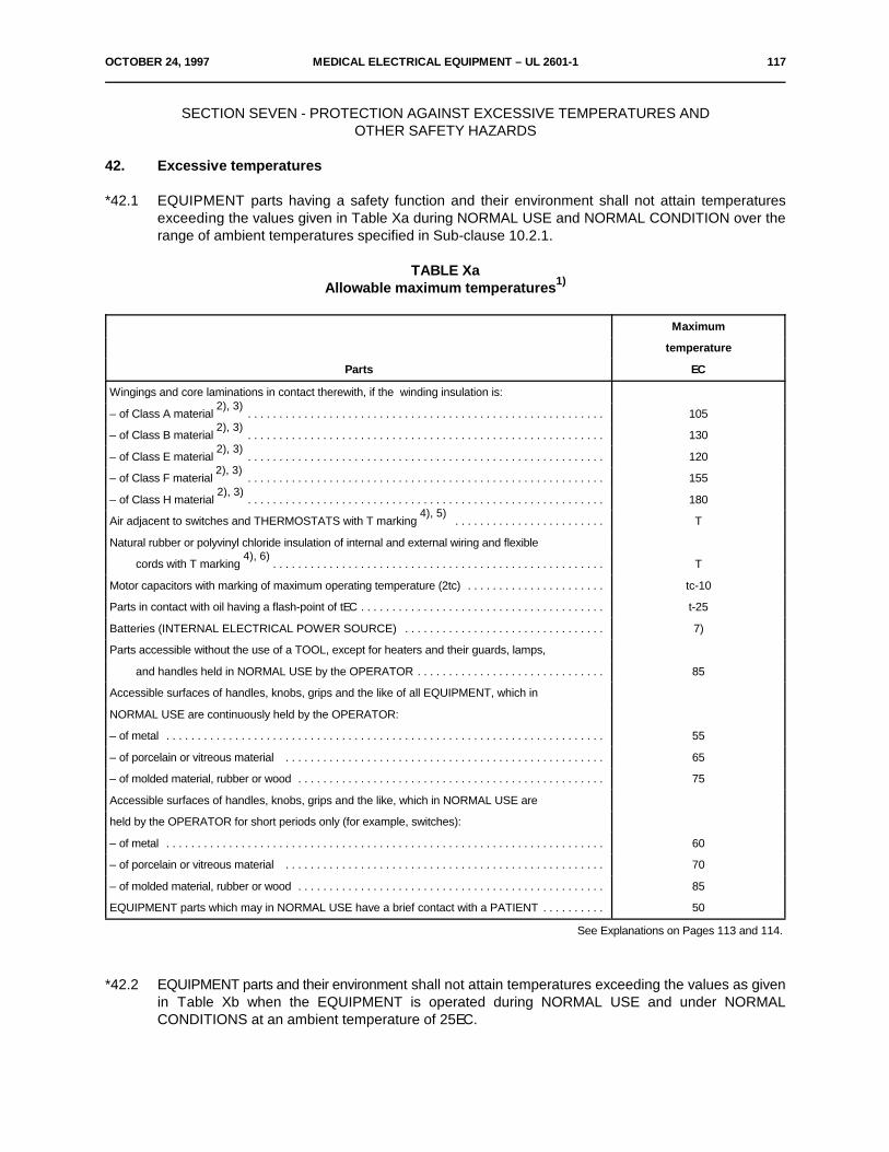
OCTOBER 24, 1997 MEDICAL ELECTRICAL EQUIPMENT – UL 2601-1 117
SECTION SEVEN - PROTECTION AGAINST EXCESSIVE TEMPERATURES ANDOTHER SAFETY HAZARDS
42. Excessive temperatures
*42.1 EQUIPMENT parts having a safety function and their environment shall not attain temperaturesexceeding the values given in Table Xa during NORMAL USE and NORMAL CONDITION over therange of ambient temperatures specified in Sub-clause 10.2.1.
TABLE XaAllowable maximum temperatures1)
Maximum
temperature
Parts EC
Wingings and core laminations in contact therewith, if the winding insulation is:
– of Class A material . . . . . . . . . . . . . . . . . . . . . . . . . . . . . . . . . . . . . . . . . . . . . . . . . . . . . . . . .2), 3)
105
– of Class B material . . . . . . . . . . . . . . . . . . . . . . . . . . . . . . . . . . . . . . . . . . . . . . . . . . . . . . . . .2), 3)
130
– of Class E material . . . . . . . . . . . . . . . . . . . . . . . . . . . . . . . . . . . . . . . . . . . . . . . . . . . . . . . . .2), 3)
120
– of Class F material . . . . . . . . . . . . . . . . . . . . . . . . . . . . . . . . . . . . . . . . . . . . . . . . . . . . . . . . .2), 3)
155
– of Class H material . . . . . . . . . . . . . . . . . . . . . . . . . . . . . . . . . . . . . . . . . . . . . . . . . . . . . . . . .2), 3)
180
Air adjacent to switches and THERMOSTATS with T marking . . . . . . . . . . . . . . . . . . . . . . . .4), 5)
T
Natural rubber or polyvinyl chloride insulation of internal and external wiring and flexible
cords with T marking . . . . . . . . . . . . . . . . . . . . . . . . . . . . . . . . . . . . . . . . . . . . . . . . . . . . .4), 6)
T
Motor capacitors with marking of maximum operating temperature (2tc) . . . . . . . . . . . . . . . . . . . . . . tc-10
Parts in contact with oil having a flash-point of tEC . . . . . . . . . . . . . . . . . . . . . . . . . . . . . . . . . . . . . . . t-25
Batteries (INTERNAL ELECTRICAL POWER SOURCE) . . . . . . . . . . . . . . . . . . . . . . . . . . . . . . . . 7)
Parts accessible without the use of a TOOL, except for heaters and their guards, lamps,
and handles held in NORMAL USE by the OPERATOR . . . . . . . . . . . . . . . . . . . . . . . . . . . . . . 85
Accessible surfaces of handles, knobs, grips and the like of all EQUIPMENT, which in
NORMAL USE are continuously held by the OPERATOR:
– of metal . . . . . . . . . . . . . . . . . . . . . . . . . . . . . . . . . . . . . . . . . . . . . . . . . . . . . . . . . . . . . . . . . . . . . . 55
– of porcelain or vitreous material . . . . . . . . . . . . . . . . . . . . . . . . . . . . . . . . . . . . . . . . . . . . . . . . . . . 65
– of molded material, rubber or wood . . . . . . . . . . . . . . . . . . . . . . . . . . . . . . . . . . . . . . . . . . . . . . . . . 75
Accessible surfaces of handles, knobs, grips and the like, which in NORMAL USE are
held by the OPERATOR for short periods only (for example, switches):
– of metal . . . . . . . . . . . . . . . . . . . . . . . . . . . . . . . . . . . . . . . . . . . . . . . . . . . . . . . . . . . . . . . . . . . . . . 60
– of porcelain or vitreous material . . . . . . . . . . . . . . . . . . . . . . . . . . . . . . . . . . . . . . . . . . . . . . . . . . . 70
– of molded material, rubber or wood . . . . . . . . . . . . . . . . . . . . . . . . . . . . . . . . . . . . . . . . . . . . . . . . . 85
EQUIPMENT parts which may in NORMAL USE have a brief contact with a PATIENT . . . . . . . . . . 50
See Explanations on Pages 113 and 114.
*42.2 EQUIPMENT parts and their environment shall not attain temperatures exceeding the values as givenin Table Xb when the EQUIPMENT is operated during NORMAL USE and under NORMALCONDITIONS at an ambient temperature of 25EC.
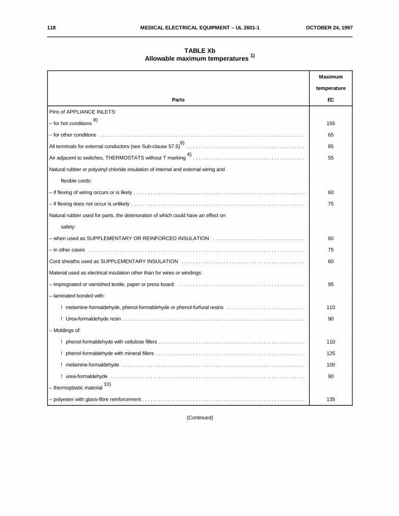
118 MEDICAL ELECTRICAL EQUIPMENT – UL 2601-1 OCTOBER 24, 1997
TABLE XbAllowable maximum temperatures 1)
Maximum
temperature
Parts EC
Pins of APPLIANCE INLETS:
– for hot conditions 1558)
– for other conditions . . . . . . . . . . . . . . . . . . . . . . . . . . . . . . . . . . . . . . . . . . . . . . . . . . . . . . . . . . . . . . . . . . . . . . . . . 65
All terminals for external conductors (see Sub-clause 57.5) . . . . . . . . . . . . . . . . . . . . . . . . . . . . . . . . . . . . . . . . . .9)
85
Air adjacent to switches, THERMOSTATS without T marking . . . . . . . . . . . . . . . . . . . . . . . . . . . . . . . . . . . . . . . .4)
55
Natural rubber or polyvinyl chloride insulation of internal and external wiring and
flexible cords:
– if flexing of wiring occurs or is likely . . . . . . . . . . . . . . . . . . . . . . . . . . . . . . . . . . . . . . . . . . . . . . . . . . . . . . . . . . . . . 60
– if flexing does not occur is unlikely . . . . . . . . . . . . . . . . . . . . . . . . . . . . . . . . . . . . . . . . . . . . . . . . . . . . . . . . . . . . . . 75
Natural rubber used for parts, the deterioration of which could have an effect on
safety:
– when used as SUPPLEMENTARY OR REINFORCED INSULATION . . . . . . . . . . . . . . . . . . . . . . . . . . . . . . . . . 60
– in other cases . . . . . . . . . . . . . . . . . . . . . . . . . . . . . . . . . . . . . . . . . . . . . . . . . . . . . . . . . . . . . . . . . . . . . . . . . . . . . 75
Cord sheaths used as SUPPLEMENTARY INSULATION . . . . . . . . . . . . . . . . . . . . . . . . . . . . . . . . . . . . . . . . . . . . 60
Material used as electrical insulation other than for wires or windings:
– impregnated or varnished textile, paper or press board: . . . . . . . . . . . . . . . . . . . . . . . . . . . . . . . . . . . . . . . . . . . . . 95
– laminated bonded with:
! melamine-formaldehyde, phenol-formaldehyde or phenol-furfural resins . . . . . . . . . . . . . . . . . . . . . . . . . . . . 110
! Urea-formaldehyde resin . . . . . . . . . . . . . . . . . . . . . . . . . . . . . . . . . . . . . . . . . . . . . . . . . . . . . . . . . . . . . . . . . 90
– Moldings of:
! phenol-formaldehyde with cellulose fillers . . . . . . . . . . . . . . . . . . . . . . . . . . . . . . . . . . . . . . . . . . . . . . . . . . . . 110
! phenol-formaldehyde with mineral fillers . . . . . . . . . . . . . . . . . . . . . . . . . . . . . . . . . . . . . . . . . . . . . . . . . . . . . 125
! melamine-formaldehyde . . . . . . . . . . . . . . . . . . . . . . . . . . . . . . . . . . . . . . . . . . . . . . . . . . . . . . . . . . . . . . . . . 100
! urea-formaldehyde . . . . . . . . . . . . . . . . . . . . . . . . . . . . . . . . . . . . . . . . . . . . . . . . . . . . . . . . . . . . . . . . . . . . . 90
– thermoplastic material 10)
– polyester with glass-fibre reinforcement . . . . . . . . . . . . . . . . . . . . . . . . . . . . . . . . . . . . . . . . . . . . . . . . . . . . . . . . . . 135
(Continued)

OCTOBER 24, 1997 MEDICAL ELECTRICAL EQUIPMENT – UL 2601-1 119
TABLE Xb (Cont'd)
– silicone rubber and the like 11)
– polytetrafluorethylene . . . . . . . . . . . . . . . . . . . . . . . . . . . . . . . . . . . . . . . . . . . . . . . . . . . . . . . . . . . . . . . . . . . . . . . . 290
– pure mica and tightly sintered ceramic material when such products are used as
SUPPLEMENTARY or REINFORCED INSULATION . . . . . . . . . . . . . . . . . . . . . . . . . . . . . . . . . . . . . . . . . . . 425
– other materials 13)
Materials used as thermal insulation and in contact with hot metal:
– laminates bonded with:
! melamine-formaldehyde, phenol-formaldehyde or phenol-furfural resins . . . . . . . . . . . . . . . . . . . . . . . . . . . . 200
! urea-formaldehyde resin . . . . . . . . . . . . . . . . . . . . . . . . . . . . . . . . . . . . . . . . . . . . . . . . . . . . . . . . . . . . . . . . . 175
– moldings of:
! phenol-formaldehyde with cellulose fillers . . . . . . . . . . . . . . . . . . . . . . . . . . . . . . . . . . . . . . . . . . . . . . . . . . . . 200
! phenol-formaldehyde with mineral fillers . . . . . . . . . . . . . . . . . . . . . . . . . . . . . . . . . . . . . . . . . . . . . . . . . . . . . 225
! melamine-formaldehyde . . . . . . . . . . . . . . . . . . . . . . . . . . . . . . . . . . . . . . . . . . . . . . . . . . . . . . . . . . . . . . . . . 175
! urea-formaldehyde . . . . . . . . . . . . . . . . . . . . . . . . . . . . . . . . . . . . . . . . . . . . . . . . . . . . . . . . . . . . . . . . . . . . . 175
– other materials 13)
Wood in general . . . . . . . . . . . . . . . . . . . . . . . . . . . . . . . . . . . . . . . . . . . . . . . . . . . . . . . . . . . . . . . . . . . . . . . . . .12)
90
Electrolytic capacitors, without a marking for tc . . . . . . . . . . . . . . . . . . . . . . . . . . . . . . . . . . . . . . . . . . . . . . . . . . . . . 65
Other capacitors, without a marking for tc . . . . . . . . . . . . . . . . . . . . . . . . . . . . . . . . . . . . . . . . . . . . . . . . . . . . . . . . . 90
Supports, walls, ceiling and floor of the test corner as described in the test of Sub-
clause 42.3 . . . . . . . . . . . . . . . . . . . . . . . . . . . . . . . . . . . . . . . . . . . . . . . . . . . . . . . . . . . . . . . . . . . . . . . . . . . . . 90
Explanations for Table Xa and Xb:1) It is recognized that higher maximum temperatures may be allowed for insulating materials under insulating oil and in
the absence of air or oxygen.
2) The classification is in accordance with IEC Publication 85.Examples of Class A material are:
– impregnated cotton, silk, artificial silk and paper; enamels based on oleo- or polyamide resins.Examples of Class B material are:– glass fibre, melamine and phenol-formaldehyde resins.Examples of Class E material are:– Moldings with cellulose fillers, cotton fabric laminates and paper laminates, bonded with melamine-formaldehyde, phenol-
formaldehyde or phenol-furfural resins;– cross-linked polyester, cellulose triacetate films, polyethylene terephthalate films;– varnished polyethylene terephthalate textile bonded with oil-modified alkyd resin varnish;– enamels based on polyvinylformal, polyurethane or epoxy resins.
120 MEDICAL ELECTRICAL EQUIPMENT – UL 2601-1 OCTOBER 24, 1997
Examples of Class F material are:– glass fibre;– varnished glass, fibre textile, built-up mica (with or without supporting material), the foregoing impregnated or bonded
with alkyd epoxy, cross-linked polyester and polyurethane resins with superior thermal stability or silicone-alkyd resins.Examples of Class H material are:– glass fibre;– varnished glass fibre impregnated or bonded with appropriate silicone resins or silicone elastomer;– built-up mica (with or without supporting materials), glass fibre laminates, the foregoing impregnated or bonded with
appropriate silicone resins.
3) Motors are required to be marked with their insulation classes or certified by the manufacturer. Totally enclosed motorswith insulation Class A, B, E, F and H may have maximum temperature values as indicated, plus 5EC.
4) T signifies the maximum operating temperature.
5) If so required by the EQUIPMENT manufacturer switches and THERMOSTATS marked with the letter T followed bythe value of the temperature limit are considered as being not marked. In this case Table Xb applies.
6) This limit will only become applicable when IEC standards for high temperature wires and flexible cords are available.
7) The operating temperature of an INTERNAL ELECTRICAL POWER SOURCE shall not attain a value which causesa SAFETY HAZARD.Such a value shall be established by consultation with the supplier of the INTERNAL ELECTRICAL POWER SOURCE.
8) The possibility of reducing the maximum temperature of the pins of APPLIANCE INLETS for hot conditions is underconsideration. See also IEC Publication 320.
9) Terminals of TRANSPORTABLE OR HAND-HELD EQUIPMENT are excluded.
10) There is no specific limit for thermoplastic material which, however, must comply with the requirements for resistanceto heat, fire or tracking, for which purpose the maximum temperature must be determined.
11) As specified by the supplier of the material.
12) The limit is concerned with the deterioration of wood and does not take into account deterioration of surface finishes.
13) Electrical or thermal insulating materials other than those given in Table Xa and Xb may be used, subject to theproduction of evidence from the manufacturer of the suitability of such materials for their intended use.
OCTOBER 24, 1997 MEDICAL ELECTRICAL EQUIPMENT – UL 2601-1 121
42.3 APPLIED PARTS OF EQUIPMENT not intended to supply heat to a PATIENT shall not have surfacetemperatures exceeding 41EC.
Compliance with the requirements of Sub-clauses 42.1 to 42.3 is checked by operation ofEQUIPMENT and temperature measurements as follows:
1) Positioning and cooling
– Heating EQUIPMENT is placed in a test corner. The test corner consists of two wallsat right angles, a floor and, if necessary, a ceiling, all of dull black painted plywoodof 20 mm thickness. The linear dimensions of the test corner shall be at least 115%of the linear dimensions of the EQUIPMENT under test.
The EQUIPMENT is positioned in the test corner as follows:
a) EQUIPMENT normally used on a floor or a table is placed as near to the walls aspossible, provided that the manufacturer has not given special instructionsconcerning its use.
b) EQUIPMENT normally fixed to a wall is mounted on one of the walls, as near to theother wall and to the floor or ceiling as is likely to occur in NORMAL USE, providedthe manufacturer has not given special instructions concerning the installation.
c) EQUIPMENT normally fixed to a ceiling is fixed to the ceiling as near to the walls asis likely to occur in NORMAL USE, provided the manufacturer has not given specialinstructions concerning its installation.
d) Other EQUIPMENT shall be tested in the position of NORMAL USE.
e) HAND-HELD EQUIPMENT is suspended in its normal position, in still air.
f) EQUIPMENT intended for installation in a cabinet or wall is built in as required byinstallation instructions, using dull black painted plywood walls, 10 mm thick whenrepresenting cabinet walls if the installation instructions so specify and 20 mm thickwhen representing building walls.
– Generally EQUIPMENT under test is operated at the prevailing ambient temperature, thevalue of which is measured. If the ambient temperature changes during the test, such achange shall be noted. Where doubts exist concerning the effectiveness of cooling meansthe test may have to be conducted at the ambient temperature which represents the leastfavorable condition, provided that this temperature is within the ambient temperature rangespecified in Sub-clause 10.2 of this Standard. If cooling liquid is used during the test theconditions of Sub-clause 10.2 shall apply.
2) Supply
– EQUIPMENT rating heating elements is operated as in NORMAL USE, with allheating elements energized unless prevented by switching interlocks, the supplyvoltage being equal to 110% of the maximum RATED voltage.
– Motor operated EQUIPMENT is operated under normal load and normal DUTYCYCLE and the least favorable voltage between 90% of the minimum RATED voltageand 110% of the maximum RATED voltage.
– Combined heating and motor operated and other EQUIPMENT shall be tested bothat 110% of the maximum RATED voltage and at 90% of the minimum RA TEDvoltage.
) t 'R2&R1
R1
(234.5 % t1) & (t2 & t )
122 MEDICAL ELECTRICAL EQUIPMENT – UL 2601-1 OCTOBER 24, 1997
3) DUTY CYCLE
The EQUIPMENT is operated:
– for the RATED operating time for EQUIPMENT for SHORT-TIME OPERATION;
– over consecutive cycles of operation until thermal-equilibrium conditions areestablished for EQUIPMENT for INTERMITTENT OPERATION, the "ON" and "OFF"periods being the RATED "ON" and "OFF" periods;
– for EQUIPMENT for CONTINUOUS OPERATION
a) until the temperature measured according to test 4) described below doesnot increase in 1 h by more than 2EC;
b) for 2.5 h, whichever is shorter.
4) Temperature measurementThe temperature of windings is determined by the resistance method unless the windings arenon-uniform or severe complications are involved in making the necessary connections forthe resistance measurement.
In this case the measurement is made by devices so chosen and positioned that they havea negligible effect on the temperature of the part under test.Devices used for determining the temperature of surfaces of walls, ceiling and floor of the testcorner shall be embedded in the surfaces or attached to the back of small blackened disksof copper or brass, 15 mm in diameter and 1 mm thick, which are flush with the surfaces.
As far as possible, EQUIPMENT is positioned so that parts likely to attain the highesttemperatures touch the disks.The value of the temperature rise of a copper winding is calculated from the formula:
where:
ªt is the temperature rise in ECR is the resistance at the beginning of the test in S1R is the resistance at the end of the test in S2R is the room temperature at the beginning of the test in EC1t is the room temperature at the end of the test in EC2
At the beginning of the test, windings are to be at room temperature. It is recommended thatthe resistance of windings at the end of the test be determined by taking resistancemeasurements as soon as possible after switching off, and then at short intervals so that acurve of resistance against time can be plotted for ascertaining the resistance at the instantof switching off
OCTOBER 24, 1997 MEDICAL ELECTRICAL EQUIPMENT – UL 2601-1 123
The temperature of electrical insulation, other than that of windings, is determined on thesurface of the insulation at places where failure could cause a short circuit, contact betweenLIVE parts and ACCESSIBLE METAL PARTS, bridging of insulation or reduction ofCREEPAGE DISTANCES or AIR CLEARANCES below the values specified in Sub-clause57.10.
The point of separation of cores of a multicore cord and where insulated wires enterlampholders are examples of places where temperatures may have to be measured.
5) Test criteria
During the test THERMAL CUT-OUTS shall not be de-activated and shall not operate. At theend of the test the maximum temperature of the parts listed in Table Xa is determined takinginto account the ambient temperature of the test environment, the temperature of the partstested and the ambient temperature range specified in Sub-clause 10.2.
For the EQUIPMENT parts listed in Table Xb the temperatures measured during the test shall,if necessary, be corrected to determine the values which would correspond to operation at anambient temperature of 25EC.
42.4 Not used.
42.5 Guards
Guards intended to prevent contact with hot accessible surfaces shall be removable only withthe aid of a TOOL.
Compliance is checked by inspection.
43. Fire prevention
EQUIPMENT shall have the strength and rigidity necessary to avoid a fire hazard which mayoccur as a result of a total or partial collapse caused by the abuses to which it is liable to be subjectedin NORMAL USE.
Compliance is checked by the mechanical strength test for enclosures (see Clause 21).
44. Overflow, spillage, leakage, humidity, ingress of liquids, cleaning, sterilization and disinfection
44.1 General
The construction of EQUIPMENT shall ensure a sufficient degree of protection againstSAFETY HAZARDS caused by overflow, spillage, leakage, humidity, ingress of liquids, cleaning,sterilization and disinfection.
124 MEDICAL ELECTRICAL EQUIPMENT – UL 2601-1 OCTOBER 24, 1997
44.2 Overflow
If EQUIPMENT incorporates a reservoir or liquid storage chamber that is liable to be over-filledor to overflow in NORMAL USE, liquid overflowing from the reservoir or chamber shall not wetelectrical safety insulation which is liable to be adversely affected by such a liquid, nor shall a SAFETYHAZARD be created. Unless restricted by a marking or by the instructions for use, no SAFETYHAZARDS shall develop if TRANSPORTABLE EQUIPMENT is tilted through an angle of 15E.
Compliance is checked by filling the liquid reservoir completely and subsequently adding afurther quantity equal to 15% of the capacity of the reservoir which is poured in steadily over a periodof 1 min.
TRANSPORTABLE EQUIPMENT is subsequently tilted through an angle of 15E in the leastfavorable direction(s) (if necessary with refilling) starting from the position of NORMAL USE.
After these procedures, EQUIPMENT shall show no signs of wetting of uninsulated LIVE partsor electrical insulation of parts which may cause a SAFETY HAZARD. For electrical insulation in caseof doubt the EQUIPMENT shall be subjected to the dielectric strength test as described in Clause 20.
44.3 Spillage
EQUIPMENT requiring the use of liquids in NORMAL USE shall be so constructed that spillagedoes not wet parts which may cause a SAFETY HAZARD.
Compliance is checked by the following test:
The EQUIPMENT is positioned as in NORMAL USE. A quantity of 200 ml of water is pouredsteadily on an arbitrary point on the top surface of the EQUIPMENT. See also Sub-clause 4.6a).
After the test, the EQUIPMENT shall comply with the requirements of this Standard.
44.4 Leakage
EQUIPMENT shall be so constructed that liquid which might escape in a SINGLE FAULTCONDITION does not wet parts which may cause a SAFETY HAZARD.
Since only small amounts of liquid will escape when they leak, sealed rechargeable batteriesare exempted from this requirement.
Compliance is checked by the following test:
By means of a pipette, drops of water shall be applied to couplings, to seals and to hoseswhich might rupture, moving parts being in operation or at rest, whichever is least favorable.
After these procedures, the EQUIPMENT shall show no signs of wetting of electrical insulationwhich is liable to be adversely affected by such a liquid. In case of doubt, it shall be subjected to thedielectric strength test as described in Clause 20.
OCTOBER 24, 1997 MEDICAL ELECTRICAL EQUIPMENT – UL 2601-1 125
44.5 Humidity
EQUIPMENT, including any detachable parts, shall be sufficiently proofed against the effectsof humidity to which it is liable to be subjected in NORMAL USE.
Compliance is checked by the preconditioning treatment and tests (see Sub-clause 4.10).
44.6 Ingress of liquids
ENCLOSURES designed to give a specified degree of protection against harmful ingress ofwater shall provide this protection in accordance with the classification of IEC Publication 529.
Compliance is checked by the following tests:
– DRIP-PROOF EQUIPMENT is checked by the test prescribed for the second characteristicnumeral 1 of IEC Publication 529.
– SPLASH-PROOF EQUIPMENT is checked by the test prescribed for the second characteristicnumeral 4 of IEC Publication 529.
– For WATER TIGHT EQUIPMENT, the test conditions shall be specified by Particular SafetyStandards but they shall not be less severe than those prescribed in IEC Publication 529 forthe second characteristic numeral 7.
Except for WATER TIGHT EQUIPMENT, EQUIPMENT shall withstand the dielectric strengthtest specified in Clause 20. Inspection shall show that water which may have entered EQUIPMENTcan have no harmful effect; in particular, there shall be no trace of water on insulation for whichCREEPAGE DISTANCES are specified in Sub-clause 57.10.
44.7 Cleaning, sterilization and disinfection
For EQUIPMENT parts which come in contact with the PATIENT in NORMAL USE, see Sub-clause 6.8.2d). EQUIPMENT or EQUIPMENT parts, including APPLIED PARTS and parts into whichPATIENTS may exhale, shall be capable of withstanding without damage or deterioration of safetyprovisions the cleaning, sterilization or disinfection processes which are likely to be encountered inNORMAL USE or which are specified by the manufacturer in the instructions for use.
Should the instructions for use restrict cleaning, sterilization or disinfection to specific methodsfor the EQUIPMENT as a whole or for parts of it, then only these specified methods shall be applied.See also Sub-clause 6.8.2d).
Compliance is checked by sterilizing or disinfecting the EQUIPMENT or EQUIPMENT parts20 times in accordance with the methods specified. If no special method of sterilization or disinfectionis specified, the test is made with saturated steam at 134EC ± 4EC for 20 cycles, each of 20 minduration (with intervals until EQUIPMENT has cooled to room temperature). There shall be noappreciable signs of deterioration. At the end of the treatment and after an adequate cooling anddrying period, EQUIPMENT or parts of it shall withstand the dielectric strength test specified in Clause20.
126 MEDICAL ELECTRICAL EQUIPMENT – UL 2601-1 OCTOBER 24, 1997
*45 Pressure vessels and parts subject to PRESSURE
The requirements of this clause apply to vessels and parts subject to PRESSURE, the ruptureof which could cause a SAFETY HAZARD.
45.1 Not used.
*45.2 If a pressure vessel is not covered by a national regulation, with or without an inspectionprocedure, and has a PRESSURE x volume content greater than 200 kPa/l, and PRESSURE greaterthan 50 kPa, it shall withstand the HYDRAULIC TEST PRESSURE.
Compliance is checked by the following tests:
Where the test PRESSURE for the EQUIPMENT is not specified by an existing NationalStandard for the part concerned, the test PRESSURE shall be the MAXIMUM PERMISSIBLEWORKING PRESSURE multiplied by a factor obtained from Figure 38.
The PRESSURE is raised gradually to the specified test value and shall be held at that valuefor 1 min. The sample shall not burst nor suffer from permanent (plastic) deformation nor leak.Leakage at a gasket during this test is not considered to constitute failure unless it occurs at aPRESSURE below 40% of the required test value, or below the MAXIMUM PERMISSIBLE WORKINGPRESSURE, whichever is greater.
No leakage is allowed for pressure vessels intended for toxic, flammable or otherwisehazardous substances.
Where pipe work and fittings (e.g. of steel and copper) made to relevant National Standardsare provided, these may be considered to have adequate strength.
Where unmarked pressure vessels and pipes cannot be hydraulically tested, integrity shallbe verified by other suitable tests, e.g. pneumatic using suitable media, at the same test PRESSUREas for the hydraulic test.
*45.3 The maximum PRESSURE to which a part can be subjected in normal or abnormal operation shallnot exceed the MAXIMUM PERMISSIBLE WORKING PRESSURE for the part.
The maximum PRESSURE in use shall be considered to be whichever is the highest of thefollowing:
a) the RATED maximum supply PRESSURE from an external source;
b) the PRESSURE setting of a pressure-relief device provided as part of the assembly;
c) the maximum PRESSURE that can be developed by an air compressor that is part of theassembly, unless the PRESSURE is limited by a pressure-relief device.
Compliance is checked by inspection.
45.4 Not used.
45.5 Not used.
45.6 Not used.

OCTOBER 24, 1997 MEDICAL ELECTRICAL EQUIPMENT – UL 2601-1 127
45.7 EQUIPMENT shall incorporate pressure-relief device(s) where excessive pressure could otherwiseoccur.
A pressure-relief device shall comply with all of the following requirements:
a) it shall be connected as close as possible to the pressure vessel or parts of the system thatit is intended to protect;
b) it shall be so installed that it is readily accessible for inspection, maintenance and repair;
c) it shall not be capable of being adjusted or rendered inoperative without the use of a TOOL;
d) it shall have its discharge opening so located and directed that the released material is notdirected towards any person;
e) it shall have its discharge opening so located and directed that operation of the device will notdeposit material on parts which may cause a SAFETY HAZARD;
f) it shall be of adequate discharge capacity to ensure that the PRESSURE will not exceed theMAXIMUM PERMISSIBLE WORKING PRESSURE of the system to which it is connected bymore than 10% in the event of a failure in the control of the supply PRESSURE;
g) there shall be no shut-off valve between a pressure-relief device and the parts that it isintended to protect;
h) the minimum number of cycles of operation shall be 100,000, except for bursting disks.
Compliance is checked by inspection and functional test.
The control device responsible for limiting the PRESSURE in the vessel shall be capable ofperforming under RATED load for 100,000 cycles of operation and shall prevent the PRESSURE fromexceeding 90% of the setting of the pressure-relief device under any condition of NORMAL USE.
45.8 Not used.
45.9 Not used.
45.10 Not used.
*46. Human errorsNot used.
47. Electrostatic chargesNot used.
*48. Materials in APPLIED PARTS in contact with the body of the PATIENTNot used.
128 MEDICAL ELECTRICAL EQUIPMENT – UL 2601-1 OCTOBER 24, 1997
49. Interruption of the power supply
49.1 THERMAL CUT-OUTS and OVER-CURRENT RELEASES with automatic resetting shall notbe used if they may cause a SAFETY HAZARD by such resetting.
Compliance is checked by a functional test.
*49.2 EQUIPMENT shall be so designed that an interruption and restoration of the power supplyshall not result in a SAFETY HAZARD other than interruption of its intended function.
Compliance is checked by interruption and restoration of relevant power supplies.
49.3 Means shall be provided to allow the mechanical constraints on a PATIENT to be removed in the eventof failure of the SUPPLY MAINS.
Compliance is checked by functional testing.
49.4 Not used.
SECTION EIGHT - ACCURACY OF OPERATING DATA AND PROTECTIONAGAINST HAZARDOUS OUTPUT
50. Accuracy of operating data
50.1 Marking of controls and instrumentsNot used. See Sub-clause 6.3.
50.2 Accuracy of controls and instrumentsNot used.
51. Protection against hazardous output
51.1 Intentional exceeding of safety limits
If the control range of EQUIPMENT is such that the delivered output in a part of the range considerablydiffers from the output which is regarded as non-hazardous, means shall be provided which preventsuch a setting or which indicate to the OPERATOR (for example by means of an apparent additionalresistance when the control is set or the bypassing of an interlock or by an additional special or audiblesignal) that the selected setting is in excess of a safety limit.
This requirement shall apply only where Particular Standards specify safe output levels.
Compliance is checked by inspection.
51.2 Indication of parameters relevant to safety
Any EQUIPMENT delivering energy or substances to a PATIENT shall indicate the possiblehazardous output, preferably as a pre-indication, e.g. energy, rate or volume.
This requirement shall apply only where Particular Standards specify it.
Compliance is checked by inspection.
OCTOBER 24, 1997 MEDICAL ELECTRICAL EQUIPMENT – UL 2601-1 129
51.3 Reliability of components
Not used (see also Sub-clause 3.6f)).
51.4 Accidental selection of excessive output values
Where EQUIPMENT is a multi-purpose unit designed for providing both low-intensity and high-intensity outputs for different treatments, appropriate steps shall be taken to minimize the possibilityof a high intensity output being selected accidentally e.g. interlocks in order to achieve deliberateaction, separated output terminals.
Compliance is checked by inspection.
SECTION NINE - ABNORMAL OPERATION AND FAULT CONDITIONS;ENVIRONMENTAL TESTS
Note – The content of this Section has been augmented and rearranged, to include a wider range of hazards and their possible causes.
52. Abnormal operation and fault conditions
52.1 EQUIPMENT shall be so designed and manufactured that even in SINGLE FAULT CONDITION noSAFETY HAZARD exists (see Sub-clause 3.1 and Clause 13).
It is assumed that EQUIPMENT is operated according to the conditions of NORMAL USE unless specified otherwisein the following tests.
Compliance is fulfilled if:
The introduction of any of the SINGLE FAULT CONDITIONS described in Sub-clause 52.5,one at a time, does not lead directly to any of the SAFETY HAZARDS described in Sub-clause 52.4.
52.2 Not used.
52.3 Not used.
52.4 The following SAFETY HAZARDS shall be taken into consideration:
*52.4.1 – emission of flames, molten metal, poisonous or ignitable gas in hazardous quantities;
– deformation of ENCLOSURES to such an extent that compliance with this Standard isimpaired;
– temperatures exceeding the maximum values shown in Table XI during the tests of Sub-clauses 52.5.10d) through 52.5.10h). These temperatures apply for an ambient temperatureof 25EC.
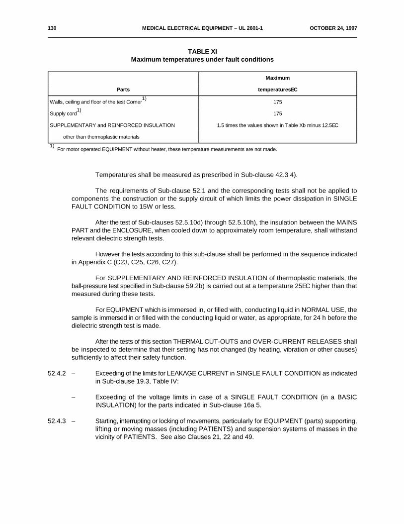
130 MEDICAL ELECTRICAL EQUIPMENT – UL 2601-1 OCTOBER 24, 1997
TABLE XIMaximum temperatures under fault conditions
Maximum
Parts temperaturesEC
Walls, ceiling and floor of the test Corner 1751)
Supply cord 1751)
SUPPLEMENTARY and REINFORCED INSULATION 1.5 times the values shown in Table Xb minus 12.5EC
other than thermoplastic materials
For motor operated EQUIPMENT without heater, these temperature measurements are not made.1)
Temperatures shall be measured as prescribed in Sub-clause 42.3 4).
The requirements of Sub-clause 52.1 and the corresponding tests shall not be applied tocomponents the construction or the supply circuit of which limits the power dissipation in SINGLEFAULT CONDITION to 15W or less.
After the test of Sub-clauses 52.5.10d) through 52.5.10h), the insulation between the MAINSPART and the ENCLOSURE, when cooled down to approximately room temperature, shall withstandrelevant dielectric strength tests.
However the tests according to this sub-clause shall be performed in the sequence indicatedin Appendix C (C23, C25, C26, C27).
For SUPPLEMENTARY AND REINFORCED INSULATION of thermoplastic materials, theball-pressure test specified in Sub-clause 59.2b) is carried out at a temperature 25EC higher than thatmeasured during these tests.
For EQUIPMENT which is immersed in, or filled with, conducting liquid in NORMAL USE, thesample is immersed in or filled with the conducting liquid or water, as appropriate, for 24 h before thedielectric strength test is made.
After the tests of this section THERMAL CUT-OUTS and OVER-CURRENT RELEASES shallbe inspected to determine that their setting has not changed (by heating, vibration or other causes)sufficiently to affect their safety function.
52.4.2 – Exceeding of the limits for LEAKAGE CURRENT in SINGLE FAULT CONDITION as indicatedin Sub-clause 19.3, Table IV:
– Exceeding of the voltage limits in case of a SINGLE FAULT CONDITION (in a BASICINSULATION) for the parts indicated in Sub-clause 16a 5.
52.4.3 – Starting, interrupting or locking of movements, particularly for EQUIPMENT (parts) supporting,lifting or moving masses (including PATIENTS) and suspension systems of masses in thevicinity of PATIENTS. See also Clauses 21, 22 and 49.

OCTOBER 24, 1997 MEDICAL ELECTRICAL EQUIPMENT – UL 2601-1 131
52.5 The following SINGLE FAULT CONDITIONS are the subject of specific requirements and tests:
During the insertion of only one fault at a time, AIR CLEARANCES and CREEPAGEDISTANCES for which requirements are specified in this Standard but are less than the specified valueshall be short-circuited simultaneously or consecutively in a combination which produces the lessfavorable result. See also Sub-clauses 17a and 17g.
52.5.1 Overloading of mains supply transformers in EQUIPMENTTests are described in Sub-clause 57.9.
52.5.2 Failure of THERMOSTATSTHERMOSTATS are short-circuited or interrupted, whichever is less favorable. See also Sub-
clauses 52.5.10 and 56.6 for overloading situations.
52.5.3 Short-circuiting of either constituent part of a DOUBLE INSULATIONEach constituent part of a DOUBLE INSULATION is short-circuited independently.
52.5.4 Interruption of the PROTECTIVE EARTH CONDUCTORTests are described in Sub-clause 19.4.
52.5.5 Impairment of coolingContrary to possible statements in the instructions for use impairments of cooling which may
occur in practice are simulated, for example:
– single ventilation fans are locked consecutively;
– ventilation through openings in top and sides is impaired by.! covering of openings in the top of the ENCLOSURE, or ! positioning of EQUIPMENT against walls;
– blocking of filters is simulated;
– the flow of a cooling agent is interrupted.Temperatures shall not exceed 1.7 times the values of Clause 42, Tables Xa and Xb, minus
17.5EC. Test conditions of Clause 42 are applied as far as possible.
52.5.6 Locking of moving parts
Moving parts are locked if EQUIPMENT:
– has accessible moving parts liable to be jammed, or– is liable to be operated while unattended (this includes EQUIPMENT which is automatically
or remotely controlled), or– has one or more motors with a locked rotor torque smaller than the full load torque.
If EQUIPMENT has more than one moving part as described above, only one part at a timeis locked. For further test requirements see Sub-clause 52.5.8.
132 MEDICAL ELECTRICAL EQUIPMENT – UL 2601-1 OCTOBER 24, 1997
*52.5.7 Interruption and short-circuiting of motor capacitors
Motors with a capacitor in the circuit of an auxiliary winding are operated with a locked rotor,with the capacitor short-circuited or open-circuited in turn.
The test with a short-circuited capacitor is not performed if the motor is provided with acapacitor complying with IEC Publication 252 and EQUIPMENT is not intended for unattended use(including automatic or remote control).
For further tests, see Sub-clause 52.5.8.
*52.5.8 Additional tests for motor operated EQUIPMENT
For every test in the SINGLE FAULT CONDITION of Sub-clauses 52.5.6 and 52.5.7, takinginto account the exemptions stated in Sub-clause 52.4.1, motor-operated EQUIPMENT shall beoperated starting from COLD CONDITION, at RATED voltage or at the upper limit of the RATEDvoltage range for the following periods of time:
a) 30 s for:– HAND-HELD EQUIPMENT,– EQUIPMENT which has to be kept switched on by hand,– EQUIPMENT which has to be kept under physical load by hand;
b) 5 min for other EQUIPMENT not in tended for unattended use:
c) for the maximum period of a timer, if such a device terminates the operation, for EQUIPMENTnot listed under a) or b);
d) as long as necessary, to establish steady thermal conditions for all the remainingEQUIPMENT.
Note – EQUIPMENT which is automatically or remotely controlled is regarded as EQUIPMENT for unattended use.
Temperatures of windings are determined at the end of the specified test periods or at theinstant of operation of fuses, THERMAL CUT-OUTS, motor protective devices and the like.
Temperatures are measured as specified in Sub-clause 42.34).
Temperatures shall not exceed the limits of Table XI.
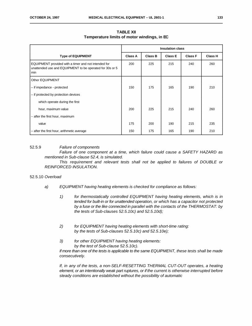
OCTOBER 24, 1997 MEDICAL ELECTRICAL EQUIPMENT – UL 2601-1 133
TABLE XIITemperature limits of motor windings, in EC
Type of EQUIPMENT Class A Class B Class E Class F Class H
Insulation class
EQUIPMENT provided with a timer and not intended for 200 225 215 240 260unattended use and EQUIPMENT to be operated for 30s or 5min
Other EQUIPMENT
– if impedance - protected 150 175 165 190 210
– if protected by protection devices
which operate during the first
hour, maximum value 200 225 215 240 260
– after the first hour, maximum
value 175 200 190 215 235
– after the first hour, arithmetic average 150 175 165 190 210
52.5.9 Failure of componentsFailure of one component at a time, which failure could cause a SAFETY HAZARD as
mentioned in Sub-clause 52.4, is simulated.This requirement and relevant tests shall not be applied to failures of DOUBLE or
REINFORCED INSULATION.
52.5.10 Overload
a) EQUIPMENT having heating elements is checked for compliance as follows:
1) for thermostatically controlled EQUIPMENT having heating elements, which is intended for built-in or for unattended operation, or which has a capacitor not protectedby a fuse or the like connected in parallel with the contacts of the THERMOSTAT: bythe tests of Sub-clauses 52.5.10c) and 52.5.10d);
2) for EQUIPMENT having heating elements with short-time rating: by the tests of Sub-clauses 52.5.10c) and 52.5.10e);
3) for other EQUIPMENT having heating elements:by the test of Sub-clause 52.5.10c).
If more than one of the tests is applicable to the same EQUIPMENT, these tests shall be madeconsecutively.
If, in any of the tests, a non-SELF-RESETTING THERMAL CUT-OUT operates, a heatingelement, or an intentionally weak part ruptures, or if the current is otherwise interrupted beforesteady conditions are established without the possibility of automatic
134 MEDICAL ELECTRICAL EQUIPMENT – UL 2601-1 OCTOBER 24, 1997
restoration, the heating period is ended. However, if the interruption is due to the rupture ofa heating element or of an intentionally weak part, the test shall be repeated on a secondsample. Open circuiting of a heating element or of an intentionally weak part in the secondsample does not in itself entail a failure to comply. Both samples shall comply with theconditions specified in Sub-clause 52.4.1.
b) EQUIPMENT having motors is checked for compliance as follows:
1) for the motor part of the EQUIPMENT, by the tests of Sub-clauses 52.5.5 through52.5.8 and 52.5.10f) through 52.5.10h), as applicable;
2) for EQUIPMENT containing motors as well as heating parts, the tests shall beperformed at the prescribed voltage, with the motor part and the heating partoperated simultaneously so as to produce the least favorable condition;
3) if more than one of the tests is applicable for the same EQUIPMENT, these tests aremade consecutively.
c) EQUIPMENT having heating elements is tested under the conditions specified in Clause 42,but without adequate heat discharge, the supply voltage being 90% or 110% of the RATEDsupply voltage, whichever is the least favorable.
If a non-SELF-RESETTING THERMAL CUT-OUT operates, or if the current is otherwiseinterrupted without the possibility of automatic restoration before steady thermal conditionsare established, the operating period is ended. If interruption of the current does not occur,EQUIPMENT shall be switched off as soon as steady thermal conditions are established andshall be allowed to cool to approximately room temperature.
For EQUIPMENT with short-time rating, the duration of the test shall be equal to the RATEDoperating time.
d) Heating parts of EQUIPMENT are tested under all of the following conditions:
1) as specified in Clause 42;2) with the EQUIPMENT operated in NORMAL CONDITION;3) with a supply voltage being 110% of the RATED supply voltage;4) disabling any control which serves to limit the temperature required in Section Seven,
except a THERMAL CUT-OUT;5) if the Equipment is provided with more than one control, they are disabled in turn.
e) Heating parts of EQUIPMENT are additionally tested under all of the following conditions:
1) as specified in Clause 42;2) with the EQUIPMENT operated in NORMAL CONDITION;3) with a supply voltage being 110% of the RATED supply voltage;4) without any control which serves to limit the temperature required in Section Seven
disabled;5) until steady thermal conditions are established, irrespective of the RATED operating
time.
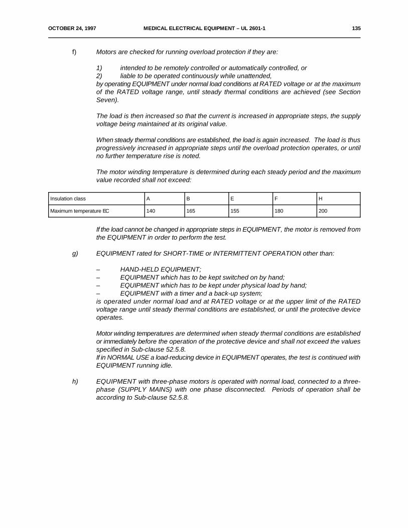
OCTOBER 24, 1997 MEDICAL ELECTRICAL EQUIPMENT – UL 2601-1 135
f) Motors are checked for running overload protection if they are:
1) intended to be remotely controlled or automatically controlled, or2) liable to be operated continuously while unattended, by operating EQUIPMENT under normal load conditions at RATED voltage or at the maximumof the RATED voltage range, until steady thermal conditions are achieved (see SectionSeven).
The load is then increased so that the current is increased in appropriate steps, the supplyvoltage being maintained at its original value.
When steady thermal conditions are established, the load is again increased. The load is thusprogressively increased in appropriate steps until the overload protection operates, or untilno further temperature rise is noted.
The motor winding temperature is determined during each steady period and the maximumvalue recorded shall not exceed:
Insulation class A B E F H
Maximum temperature EC 140 165 155 180 200
If the load cannot be changed in appropriate steps in EQUIPMENT, the motor is removed fromthe EQUIPMENT in order to perform the test.
g) EQUIPMENT rated for SHORT-TIME or INTERMITTENT OPERATION other than:
– HAND-HELD EQUIPMENT;– EQUIPMENT which has to be kept switched on by hand;– EQUIPMENT which has to be kept under physical load by hand;– EQUIPMENT with a timer and a back-up system;is operated under normal load and at RATED voltage or at the upper limit of the RATEDvoltage range until steady thermal conditions are established, or until the protective deviceoperates.
Motor winding temperatures are determined when steady thermal conditions are establishedor immediately before the operation of the protective device and shall not exceed the valuesspecified in Sub-clause 52.5.8.If in NORMAL USE a load-reducing device in EQUIPMENT operates, the test is continued withEQUIPMENT running idle.
h) EQUIPMENT with three-phase motors is operated with normal load, connected to a three-phase (SUPPLY MAINS) with one phase disconnected. Periods of operation shall beaccording to Sub-clause 52.5.8.

136 MEDICAL ELECTRICAL EQUIPMENT – UL 2601-1 OCTOBER 24, 1997
53. ENVIRONMENTAL TESTS
See Sub-clause 4.10 and Clause 10.
SECTION TEN - CONSTRUCTIONAL REQUIREMENTS
*54. General
The following requirements in Section Ten specify details of the electrical and mechanicalconstruction insofar as the safety of EQUIPMENT is concerned.
The aim is to specify requirements in such a manner as to allow manufacturers the widestpossible choice in design and construction.
As allowed in Sub-clause 3.4, a manufacturer may make use of materials and constructionsdiffering from those detailed in this Section, if an equivalent degree of safety is obtained. Therequirements of this Section are considered as not more than one means of achieving the requireddegree of safety and the term "shall", where used, should be understood accordingly.
*54.1 Arrangements of functionsNot used.
*54.2 ServiceabilityNot used.
*54.3 Inadvertent changing of settingsNot used.
55. ENCLOSURES and covers
Not used. See Clauses 16, 21 and 24.
*55.1 MaterialsNot used.
*55.2 Mechanical strengthNot used.
55.3 ACCESS COVERSNot used.
55.4 Grips and other handling devicesNot used. Moved to Sub-clauses 21 c) and 24.6.
56. Components and general assembly
56.1 General
a) Not used.
OCTOBER 24, 1997 MEDICAL ELECTRICAL EQUIPMENT – UL 2601-1 137
b) Marking of components
Ratings of components shall not conflict with the conditions of use in EQUIPMENT.
All components in the MAINS PART and in the APPLIED PART shall be marked or otherwiseidentified so that their ratings can be ascertained.The markings may be integral with the parts themselves, or made available by reference toconstruction drawings, parts lists, or in the ACCOMPANYING DOCUMENTS.
Compliance is checked by inspection of the ratings of components to ascertain that no conflictexists with the condition of use in EQUIPMENT.
c) Supporting of componentsNot used.
d) Component fixingComponents, the unwanted movement of which could result in a SAFETY HAZARD, shall bemounted securely to prevent such movement.
Compliance is checked by inspection.
e) Resistance of components to vibration.
Not used.
f) Fixing of wiringConductors and connectors shall be so secured and/or insulated that accidental detachmentshall not result in a SAFETY HAZARD. They are not considered to be adequately secured ifon breaking free at their joint and moving about their support point they are capable oftouching circuit points giving rise to a SAFETY HAZARD.
One instance of breaking free shall be considered to be a SINGLE FAULT CONDITION.
Compliance is checked by inspection.
56.2 Screws and nutsNot used.
56.3 Connections – General
For connections and connectors in the MAINS PART see Sub-clauses 57.2 and 57.5.
a) Construction of connectorsDesign and construction of electrical, hydraulic, pneumatic and gas connection terminals andconnectors shall be such that incorrect connection of accessible connectors, removablewithout the use of a TOOL, shall be prevented where a SAFETY HAZARD may be caused.
– Connectors shall comply with Sub-clause 17g.
– Plugs for connection of PATIENT CIRCUIT leads shall be so designed that theycannot be connected to other outlets on the same EQUIPMENT intended for otherfunctions, unless it can be proven that no SAFETY HAZARD can result.

138 MEDICAL ELECTRICAL EQUIPMENT – UL 2601-1 OCTOBER 24, 1997
– Medical gas connections on EQUIPMENT for different gases to be operated inNORMAL USE shall not be interchangeable. See also Sub-clause 6.6 and ISORecommendation R407.
Compliance is checked by inspection, if possible by interchanging of connections, to establishthe absence of a SAFETY HAZARD (LEAKAGE CURRENT exceeding the values in NORMALCONDITION, movement, temperature, radiation, etc.).
b) Connections between different parts of EQUIPMENT. See also Clause 58.Detachable flexible cords used for interconnection of different parts of EQUIPMENT shall beprovided with means for connection such that ACCESSIBLE METAL PARTS cannot becomeLIVE when a connection is loosened or broken due to the disengagement of one of theconnecting means.
Compliance is checked by inspection and measurement and, if necessary, by a test with thestandard test finger according to Sub-clause 16a.
*56.4 Connections of capacitors
– Capacitors shall not be connected between LIVE parts and non-PROTECTIVELY EARTHEDACCESSIBLE PARTS where the failure of such a capacitor could result in ACCESSIBLEPARTS becoming LIVE.
– Capacitors connected directly between the MAINS PART and PROTECTIVELY EARTHEDACCESSIBLE METAL PARTS shall comply with the requirements of IEC Publication 384-14or equivalent.
– The ENCLOSURE of capacitors connected to the MAINS PART and providing only BASICINSULATION shall not be secured directly to non-PROTECTIVELY EARTH ED ACCESSIBLEMETAL PARTS.
– Capacitors or other spark-suppression devices shall not be connected between the contactsof THERMAL CUT-OUTS.
Compliance is checked by inspection.
56.5 Protective devices
EQUIPMENT shall not be fitted with protective devices which cause disconnection of theEQUIPMENT from the SUPPLY MAINS by producing a short-circuit which results in operation of anovercurrent protection device. See also Sub-clause 59.3.
Compliance is checked by inspection.
56.6 Temperature and overload control devices
a) Application– THERMAL CUT-OUTS with a safety function which have to be reset by a soldering
operation which may affect the operating value shall not be fitted in EQUIPMENT.
– Thermal safety devices shall be provided where necessary to prevent operatingtemperatures exceeding the limits specified in Section Nine and in Sub-clause 57.9.
OCTOBER 24, 1997 MEDICAL ELECTRICAL EQUIPMENT – UL 2601-1 139
– Where a failure of a THERMOSTAT could constitute a SAFETY HAZARD anindependent non-SELF-RESETTING THERMAL CUT-OUT shall additionally beprovided. The temperature of operation of the additional device shall be outside thatattainable at the extreme setting of the normal control device but shall be within thesafe temperature limit for its intended function.
– Where the consequent loss of function of EQUIPMENT caused by operation of aTHERMAL CUT-OUT presents a SAFETY HAZARD, an audible warning shall begiven.
Compliance is checked by inspection and, if applicable, by the following tests:Thermal safety devices may be tested separately from EQUIPMENT.THERMAL CUT-OUTS and OVER-CURRENT RELEASES shall be tested by operating theEQUIPMENT under the conditions described in Section Nine.SELF-RESETTING THERMAL CUT-OUTS and self-resetting OVER-CURRENT RELEASESshall be caused to operate 200 times.Non-self resetting OVER CURRENT RELEASES shall be caused to operate 10 times.
During the tests, forced cooling and resting periods may be introduced to prevent damage tothe EQUIPMENT. After the tests, the samples shall show no damage impairing their furtheruse.
EQUIPMENT which incorporates a fluid filled container having heating facilities shall beprovided with a safety device to safeguard against overheating in the event of the heater beingswitched on with the container empty, if dangerous overheating can occur in the absence offluid.
Compliance is checked by operating the relevant EQUIPMENT with an empty container. Nooverheating shall occur which causes damage to the EQUIPMENT resulting in a SAFETYHAZARD.
b) Allowable temperature range
– Where means are provided for varying the temperature setting of THERMOSTATS,the temperature range shall not exceed substantially that which is necessary for theproper functioning of EQUIPMENT and the temperature setting shall be clearlyindicated.
– The operating temperature of THERMAL CUT-OUTS shall be clearly indicated.
Compliance is checked by inspection.
56.7 INTERNAL ELECTRICAL POWER SOURCE
a) Housing
Housings containing batteries from which gases can escape during charging or dischargingshall be ventilated to minimize the risk of accumulation and ignition.
Battery compartments shall be designed to prevent the risk of accidentally short-circuiting thebattery where such short circuits could result in a SAFETY HAZARD.
Compliance is checked by inspection.
140 MEDICAL ELECTRICAL EQUIPMENT – UL 2601-1 OCTOBER 24, 1997
b) Connection
If a SAFETY HAZARD might develop by the incorrect connection or replacement of a battery,EQUIPMENT shall be fitted with a means of preventing incorrect polarity of connection. Seealso Sub-clause 6.2d.
Compliance is checked by:
1) Establishing the possibility of making an incorrect battery connection.2) Where this possibility exists, establishing the effect of an incorrect battery connection.
56.8 Indicators
Unless indication is otherwise apparent to the OPERATOR, indicator lights shall be provided:– To indicate that EQUIPMENT is energized.– On EQUIPMENT incorporating non-luminous heaters to indicate that the heaters are
operative if a SAFETY HAZARD could result.This does not apply to heated stylus-pens for recording purposes.
– To indicate that an output exists where an inadvertent or prolonged operation of theoutput circuit could constitute a SAFETY HAZARD.Colors, of indicator lights are described in Sub-clause 6.7.In EQUIPMENT incorporating a means for charging an INTERNAL ELECTRICAL
POWER SOURCE the charging mode shall be visibly indicated to the OPERATOR.Compliance is checked by inspection of the presence and function of indicating
means visible from the position of NORMAL USE.
56.9 Pre-set controlsNot used.
56.10 Actuating parts of controls
a) Protection against electric shockACCESSIBLE PARTS of electrical controls shall comply with the requirements of Sub-clause16c.
b) Fixing, prevention of maladjustment– All actuating parts shall be so secured that they cannot be pulled off or work loose
during NORMAL USE.– Controls, the adjustment of which can present a SAFETY HAZARD to the PATIENT
or OPERATOR while EQUIPMENT is in use, shall be so secured that the indicationof any scale always corresponds with the position of the control.The indication in this case refers to "On" or "Off" position, scale markings or otherindications of position.
– Incorrect connection of the indicating device to the relevant component shall beprevented by an adequate construction, if it can be separated without the use of aTOOL.
Compliance is checked by inspection and manual tests. For rotating controls, the torques asshown in Table XIII shall be applied between the control knob and the shaft for not less than2s in each direction alternately. The test shall be repeated 10 times.
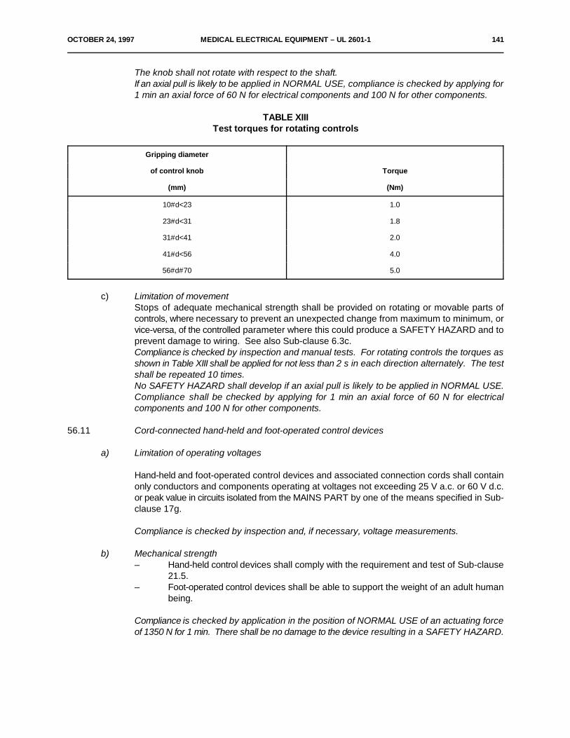
OCTOBER 24, 1997 MEDICAL ELECTRICAL EQUIPMENT – UL 2601-1 141
The knob shall not rotate with respect to the shaft.If an axial pull is likely to be applied in NORMAL USE, compliance is checked by applying for1 min an axial force of 60 N for electrical components and 100 N for other components.
TABLE XIIITest torques for rotating controls
Gripping diameter
of control knob Torque
(mm) (Nm)
10#d<23 1.0
23#d<31 1.8
31#d<41 2.0
41#d<56 4.0
56#d#70 5.0
c) Limitation of movementStops of adequate mechanical strength shall be provided on rotating or movable parts ofcontrols, where necessary to prevent an unexpected change from maximum to minimum, orvice-versa, of the controlled parameter where this could produce a SAFETY HAZARD and toprevent damage to wiring. See also Sub-clause 6.3c.Compliance is checked by inspection and manual tests. For rotating controls the torques asshown in Table XIII shall be applied for not less than 2 s in each direction alternately. The testshall be repeated 10 times.No SAFETY HAZARD shall develop if an axial pull is likely to be applied in NORMAL USE.Compliance shall be checked by applying for 1 min an axial force of 60 N for electricalcomponents and 100 N for other components.
56.11 Cord-connected hand-held and foot-operated control devices
a) Limitation of operating voltages
Hand-held and foot-operated control devices and associated connection cords shall containonly conductors and components operating at voltages not exceeding 25 V a.c. or 60 V d.c.or peak value in circuits isolated from the MAINS PART by one of the means specified in Sub-clause 17g.
Compliance is checked by inspection and, if necessary, voltage measurements.
b) Mechanical strength– Hand-held control devices shall comply with the requirement and test of Sub-clause
21.5.– Foot-operated control devices shall be able to support the weight of an adult human
being.
Compliance is checked by application in the position of NORMAL USE of an actuating forceof 1350 N for 1 min. There shall be no damage to the device resulting in a SAFETY HAZARD.

142 MEDICAL ELECTRICAL EQUIPMENT – UL 2601-1 OCTOBER 24, 1997
c) Inadvertent operationHand-held and foot-operated control devices shall not change their control setting wheninadvertently placed in an abnormal position.Compliance is checked by turning the device in all possible abnormal positions and placingit as such on a supporting surface. There shall not be any inadvertent change of controlsetting resulting in a SAFETY HAZARD.
d) Entry of liquids– Foot-operated control devices shall be drip-proof.
Compliance is checked as described in Sub-clause 44.6 for DRIP-PROOF EQUIPMENT.
– The electrical switching parts of foot-operated control devices of EQUIPMENT,specified by the manufacturer for use in operating rooms, shall be of watertightconstruction.
Compliance is checked as described in Sub-clause 44.6 for WATERTIGHT EQUIPMENT.
e) Connection cordsThe connection and anchorage of a flexible cord to a hand-held or foot-operated controldevice at the entry point to the control device shall comply with the requirements specified forflexible supply cords in Sub-clause 57.4.Compliance is checked by performance of the tests of Sub-clause 57.4.
57. MAINS PARTS, components and layout
57.1 Isolation from the SUPPLY MAINS
a) Isolation– EQUIPMENT shall have means to isolate its circuits electrically from the SUPPLY
MAINS on all poles simultaneously. This isolation shall include each LIVE supplyconductor, except that PERMANENTLY INSTALLED EQUIPMENT connected to apolyphase SUPPLY MAINS may be provided with a device which does not interruptthe neutral conductor, but only if local installation conditions are such that in NORMALCONDITION the voltage on the neutral conductor can be expected not to exceedextra-low voltage.
– Means for isolation shall either be incorporated in EQUIPMENT or, if external, shallbe specified in the ACCOMPANYING DOCUMENTS (see Sub-clause 6.8.3).
b) Not used.
c) Not used. See Sub-clause 57.1a.
d) Switches that are used to comply with Sub-clause 57.1a shall comply with the CREEPAGEDISTANCES and AIR CLEARANCES as specified in IEC Publication 328.
e) Not used.
f) Mains switches shall not be incorporated in a POWER SUPPLY CORD or any other externalflexible lead.
g) The directions of movement of the actuators of switches that are used to comply with Sub-clause 57.1a shall comply with IEC Publication 447.

OCTOBER 24, 1997 MEDICAL ELECTRICAL EQUIPMENT – UL 2601-1 143
h) In non-PERMANENTLY INSTALLED EQUIPMENT a suitable plug device used to isolateEQUIPMENT from the SUPPLY MAINS shall be considered as complying with therequirements of Sub-clause 57.1a.APPLIANCE COUPLERS and flexible cords with MAINS PLUGS are suitable plug devices.
j) Not used. See Sub-clause 57.1a.
k) Not used.
l) Not used.
m) Fuses and semiconductor devices shall not be used as isolating devices in the sense of thissub-clause.Compliance is checked by inspection.
Table XIV. Not used.
57.2 MAINS CONNECTORS, APPLIANCE INLETS and the like
a) Not used.
b) Not used.
c) Not used.
d) Not used.
*e) AUXILIARY MAINS SOCKET OUTLETS on non-PERMANENTLY INSTALLED EQUIPMENT,intended for the provision of mains supply to other EQUIPMENT, or to separated parts ofEQUIPMENT shall be of a type that cannot accept a MAINS PLUG. See also Sub-clause56.3.
This requirement does not apply to EMERGENCY TROLLEYS.Such AUXILIARY MAINS SOCKET OUTLETS shall be properly marked (see Sub-clause6.1k).Compliance is checked by inspection.
f) Not used.
57.3 POWER SUPPLY CORDS
a) Application– EQUIPMENT shall not be provided with more than one connection to a particular
SUPPLY MAINS.– If a facility for alternative connection to a different supply system, e.g. external battery,
is provided no SAFETY HAZARD shall occur when more than one connection ismade simultaneously.
– MAINS PLUGS shall not be fitted with more than one POWER SUPPLY CORD.– EQUIPMENT which is not intended to be permanently connected to fixed wiring shall
be provided with either a POWER SUPPLY CORD or an APPLIANCE INLET.
Compliance is checked by inspection.
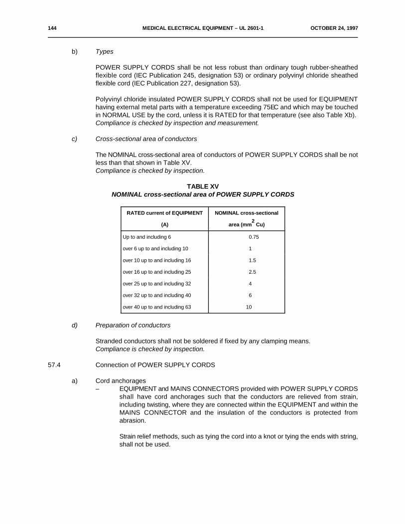
144 MEDICAL ELECTRICAL EQUIPMENT – UL 2601-1 OCTOBER 24, 1997
b) Types
POWER SUPPLY CORDS shall be not less robust than ordinary tough rubber-sheathedflexible cord (IEC Publication 245, designation 53) or ordinary polyvinyl chloride sheathedflexible cord (IEC Publication 227, designation 53).
Polyvinyl chloride insulated POWER SUPPLY CORDS shall not be used for EQUIPMENThaving external metal parts with a temperature exceeding 75EC and which may be touchedin NORMAL USE by the cord, unless it is RATED for that temperature (see also Table Xb).Compliance is checked by inspection and measurement.
c) Cross-sectional area of conductors
The NOMINAL cross-sectional area of conductors of POWER SUPPLY CORDS shall be notless than that shown in Table XV.Compliance is checked by inspection.
TABLE XVNOMINAL cross-sectional area of POWER SUPPLY CORDS
RATED current of EQUIPMENT NOMINAL cross-sectional
(A) area (mm Cu)2
Up to and including 6 0.75
over 6 up to and including 10 1
over 10 up to and including 16 1.5
over 16 up to and including 25 2.5
over 25 up to and including 32 4
over 32 up to and including 40 6
over 40 up to and including 63 10
d) Preparation of conductors
Stranded conductors shall not be soldered if fixed by any clamping means.Compliance is checked by inspection.
57.4 Connection of POWER SUPPLY CORDS
a) Cord anchorages– EQUIPMENT and MAINS CONNECTORS provided with POWER SUPPLY CORDS
shall have cord anchorages such that the conductors are relieved from strain,including twisting, where they are connected within the EQUIPMENT and within theMAINS CONNECTOR and the insulation of the conductors is protected fromabrasion.
Strain relief methods, such as tying the cord into a knot or tying the ends with string,shall not be used.
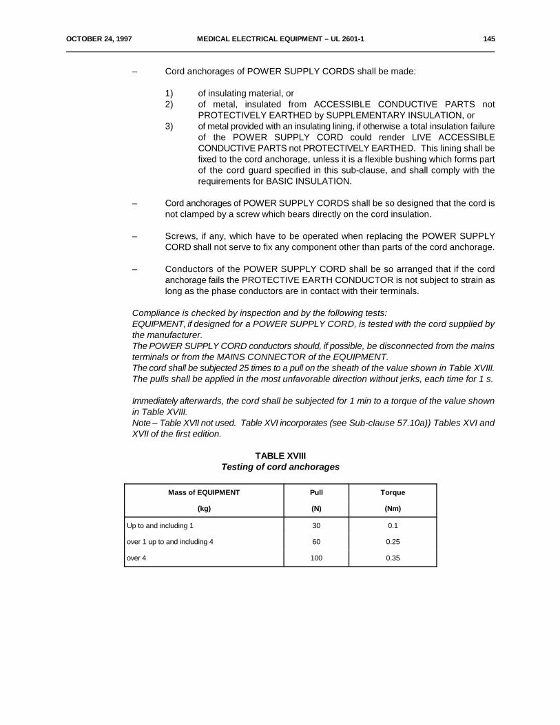
OCTOBER 24, 1997 MEDICAL ELECTRICAL EQUIPMENT – UL 2601-1 145
– Cord anchorages of POWER SUPPLY CORDS shall be made:
1) of insulating material, or2) of metal, insulated from ACCESSIBLE CONDUCTIVE PARTS not
PROTECTIVELY EARTHED by SUPPLEMENTARY INSULATION, or3) of metal provided with an insulating lining, if otherwise a total insulation failure
of the POWER SUPPLY CORD could render LIVE ACCESSIBLECONDUCTIVE PARTS not PROTECTIVELY EARTHED. This lining shall befixed to the cord anchorage, unless it is a flexible bushing which forms partof the cord guard specified in this sub-clause, and shall comply with therequirements for BASIC INSULATION.
– Cord anchorages of POWER SUPPLY CORDS shall be so designed that the cord isnot clamped by a screw which bears directly on the cord insulation.
– Screws, if any, which have to be operated when replacing the POWER SUPPLYCORD shall not serve to fix any component other than parts of the cord anchorage.
– Conductors of the POWER SUPPLY CORD shall be so arranged that if the cordanchorage fails the PROTECTIVE EARTH CONDUCTOR is not subject to strain aslong as the phase conductors are in contact with their terminals.
Compliance is checked by inspection and by the following tests:EQUIPMENT, if designed for a POWER SUPPLY CORD, is tested with the cord supplied bythe manufacturer.The POWER SUPPLY CORD conductors should, if possible, be disconnected from the mainsterminals or from the MAINS CONNECTOR of the EQUIPMENT.The cord shall be subjected 25 times to a pull on the sheath of the value shown in Table XVIII.The pulls shall be applied in the most unfavorable direction without jerks, each time for 1 s.
Immediately afterwards, the cord shall be subjected for 1 min to a torque of the value shownin Table XVIII.Note – Table XVII not used. Table XVI incorporates (see Sub-clause 57.10a)) Tables XVI andXVII of the first edition.
TABLE XVIIITesting of cord anchorages
Mass of EQUIPMENT Pull Torque
(kg) (N) (Nm)
Up to and including 1 30 0.1
over 1 up to and including 4 60 0.25
over 4 100 0.35
146 MEDICAL ELECTRICAL EQUIPMENT – UL 2601-1 OCTOBER 24, 1997
After the tests, the cord sheath shall not have been longitudinally displaced by more than 2mm and the conductor ends shall not have moved over a distance of more than l mm fromtheir normally connected position.CREEPAGE DISTANCES and AIR CLEARANCES shall not be reduced below the valuesspecified in Sub-clause 57.10.For the measurement of the longitudinal displacement, a mark shall be made on the cordsheath while it is subjected to the first pull, at a distance of approximately 2 cm from the cordanchorage or other suitable point between the cord anchorage and the test apparatus.
This displacement of the mark on the cord sheath in relation to the cord anchorage or otherpoint shall be measured while the cord is subjected to the last pull.It shall not be possible to push the cord into EQUIPMENT to such an extent that the cord, orinternal parts of the EQUIPMENT, could be damaged.
b) Cord guards
POWER SUPPLY CORDS of other than STATIONARY EQUIPMENT shall be protectedagainst excessive bending at the inlet opening of EQUIPMENT by means of a cord guard ofinsulating material.Alternatively, an opening in EQUIPMENT shall be so shaped that the applied supply cord,even if not provided with a guard, passes the following flexing test.
Compliance is checked by inspection, by measurement and by the following test(s):EQUIPMENT designed for a POWER SUPPLY CORD is fitted with a cord guard or openingand the POWER SUPPLY CORD shall have an exposed length of approximately 100 mm.The EQUIPMENT is so held that the axis of the cord guard, where the cord leaves it, projectsupward at an angle of 45E to the horizontal when the cord is free from stress.
A mass equal to 10 D g is then attached to the free end of the cord, D being the overall2
diameter, in millimeters, or, for flat cords, the minor overall dimensions of the POWERSUPPLY CORD delivered with the EQUIPMENT.If the cord guard is temperature sensitive, the test is made at 23E±2EC.Flat cords are bent in a direction perpendicular to the plane containing the axis of the cores.
Immediately after the mass has been attached, the curvature of the cord shall nowhere be lessthan 1.5 D, being checked by a cylindrical rod with a diameter of 1.5 D.
Guards which fail the above dimensional test shall pass the following test:
A sample of the guard, together with the cord delivered with the EQUIPMENT, is to besubjected to 5000 cycles of flexing. The guard is mounted in the EQUIPMENT with a 60 cmto 100 cm length of cord. With the EQUIPMENT held stationary, the guard is flexed by movingthe cord back and forth in a plane through an angle of approximately 180E.After the test, the cord shall not have worked loose and neither the cord anchorage nor thecord shall show appreciable damage, except that not more than 10% of the total number ofconductor strands may have been broken.
OCTOBER 24, 1997 MEDICAL ELECTRICAL EQUIPMENT – UL 2601-1 147
c) Accessibility of the connectionThe space inside EQUIPMENT designed for fixed wiring or a rewirable POWER SUPPLYCORD shall be adequate to allow conductors to be easily introduced and connected, andcovers, if any, to be fitted without risk of damage to the conductors or their insulation. It shallbe possible to check that the conductors are correctly connected and positioned before thecover is fitted.Compliance is checked by inspection and by an installation test.
57.5 MAINS TERMINAL DEVICES and wiring of MAINS PART
*a) General requirements for MAINS TERMINAL DEVICESEQUIPMENT intended to be permanently connected to fixed wiring and EQUIPMENT intendedto be connected by means of rewirable non-detachable POWER SUPPLY CORDS shall beprovided with MAINS TERMINAL DEVICES in which connection shall be made by means ofscrews, nuts or equally effective methods.Reliance shall not be placed upon the terminals alone to maintain the conductors in position,unless barriers are provided such that CREEPAGE DISTANCES and AIR CLEARANCESbetween LIVE parts and other conductive parts cannot be reduced to less than the valuesspecified in Sub-clause 57.10, should the conductor break away.
Terminals of components other than terminal blocks may be used as terminals intended forexternal conductors if they comply with the requirements of this sub-clause and are properlymarked according to Sub-clauses 6.2 h), j) and k).
Screws and nuts which clamp external conductors shall not serve to fix any other component,except that they may also clamp internal conductors if these are so arranged that they areunlikely to be displaced when fitting the supply conductors.
Compliance is checked by inspection.
b) Arrangement of MAINS TERMINAL DEVICES
– For EQUIPMENT with rewirable cords where terminals are provided for theconnection of external cords or flexible supply cords, these terminals together withany PROTECTIVE EARTH TERMINAL shall be closely grouped, so as to provide aconvenient means of connection.
– For details of PROTECTIVE EARTH CONDUCTOR connections see Clause 58.– For marking of MAINS TERMINAL DEVICES see Sub-clause 6.2.
– MAINS TERMINAL DEVICES shall not be accessible without the use of a TOOL, evenif their LIVE parts are not accessible.
Compliance is checked by inspection.– MAINS TERMINAL DEVICES shall be so located or shielded that, should a wire of a
stranded conductor escape when the conductors are fitted, there is no risk ofaccidental contact between LIVE parts and ACCESSIBLE PARTS and, for CLASS IlEQUIPMENT, between LIVE parts and conductive parts separated fromACCESSIBLE PARTS by SUPPLEMENTARY INSULATION only.
Compliance is checked by inspection and, in case of doubt, by the following test:The end of a flexible conductor having the NOMINAL cross-sectional area specified in Sub-clause 57.3c) (Table XV) is stripped of its insulation for a length of 8 mm.A single wire of the stranded conductor is left free and the rest of the conductor is secured tothe terminal.
148 MEDICAL ELECTRICAL EQUIPMENT – UL 2601-1 OCTOBER 24, 1997
The free wire is bent in every possible direction without pulling back the insulating sheath andwithout making sharp bends around partitions.The free wire of a conductor connected to a LIVE terminal shall not come into contact with anyACCESSIBLE PARTS or parts connected to ACCESSIBLE PARTS, or, for CLASS IIEQUIPMENT, parts which are separated from ACCESSIBLE PARTS by SUPPLEMENTARYINSULATION only.The free wire of a conductor connected to a PROTECTIVE EARTH TERMINAL shall not comeinto contact with any LIVE part (see Sub-clause 57.5a)).
c) Fixing of mains terminals
Terminals of EQUIPMENT shall be so fixed that, when the means for clamping the conductorsare tightened or loosened, the internal wiring is not subjected to stress and CREEPAGEDISTANCES and AIR CLEARANCES are not reduced below the values specified in Sub-clause 57.10.Compliance is checked by inspection and by measurement after fastening and loosening aconductor of the largest cross-sectional area specified 10 times.
*d) Connections to mains terminals
– For EQUIPMENT with rewirable flexible cords to be connected by clamping meansthe cord terminals shall not require special preparation of the conductor in order toeffect correct connection, and they shall be so designed or placed that the conductoris not damaged and cannot slip out when the clamping screws or nuts are tightened.
– For further requirements limiting conductor preparation in POWER SUPPLY CORDSand DETACHABLE POWER SUPPLY CORDS see Sub-clause 57.3d).
Compliance is checked by inspection of the terminals and of the conductors after the test ofSub-clause 57.5c).
e) Fixing of wiring
Not used. See Sub-clause 56.1f).
57.6 Mains fuses and OVER-CURRENT RELEASES
Fuses or OVER-CURRENT RELEASES shall be provided in each supply lead for CLASS IEQUIPMENT and for CLASS II EQUIPMENT having a functional earth according to Sub-clause 18 l)and in at least one supply lead for other single-phase CLASS II EQUIPMENT.
The current rating of mains fuses and OVER-CURRENT RELEASES shall be such that theyreliably carry the normal operating current and shall not be greater than the current rating of anycomponent in the mains circuit carrying the mains supply current.– A PROTECTIVE EARTH CONDUCTOR shall not be fused.– For PERMANENTLY INSTALLED EQUIPMENT the neutral conductor shall not be fused.
Compliance is checked by inspection.
*57.7 Location of interference suppressors in the MAINS PARTNot used.
OCTOBER 24, 1997 MEDICAL ELECTRICAL EQUIPMENT – UL 2601-1 149
57.8 Wiring of the MAINS PART
a) InsulationIf the insulation of an individual conductor in the MAINS PART is not at least electricallyequivalent to that of the individual conductors of flexible supply cords complying with IECPublications 227 or 245, that conductor shall be considered to be a bare conductor.
Compliance is established by checking the insulation of conductors in the MAINS PART.
b) Cross-section– Internal wiring in a MAINS PART between the MAINS TERMINAL DEVICE and the
protective devices shall have a cross-sectional area not less than the minimumrequired for the POWER SUPPLY CORD as specified in Sub-clause 57.3c).
Compliance is checked by inspection.– The cross-sectional area of other wiring in the MAINS PART and the sizes of tracks
on printed wiring circuits shall be sufficient to prevent any fire hazard in case ofpossible fault currents.If any doubt exists concerning the adequacy of incorporated overcurrent protection,compliance is checked by connecting the EQUIPMENT to a specified SUPPLYMAINS from which the most unfavorable short-circuit current expected can be drawnin the event of a fault in the MAINS PART.Subsequently, a fault in a single insulation in the MAINS PART is simulated so thatthe fault current is the least favorable. No SAFETY HAZARD shall arise.
*57.9 Mains supply transformersMains supply transformers shall comply with the following requirements:
57.9.1 Overheating– Mains supply transformers used in MEDICAL ELECTRICAL EQUIPMENT shall be protected
against overheating of BASIC INSULATION, SUPPLEMENTARY INSULATION andREINFORCED INSULATION in the event of short-circuit or overload on any output winding.
Compliance is checked by the tests described in Sub-clauses 57.9.1 a) and 57.9.1 b).– Where protective devices external to the transformer or transformer ENCLOSURE provide the
protection against overheating e.g. fuses, OVERCURRENT RELEASES, THERMAL,CUTOUTS, these devices shall be connected in such a way that failure of any componentother than wiring interposed between the protective devices and the transformer cannot renderthe protective devices inoperative.
Compliance is checked by inspection.
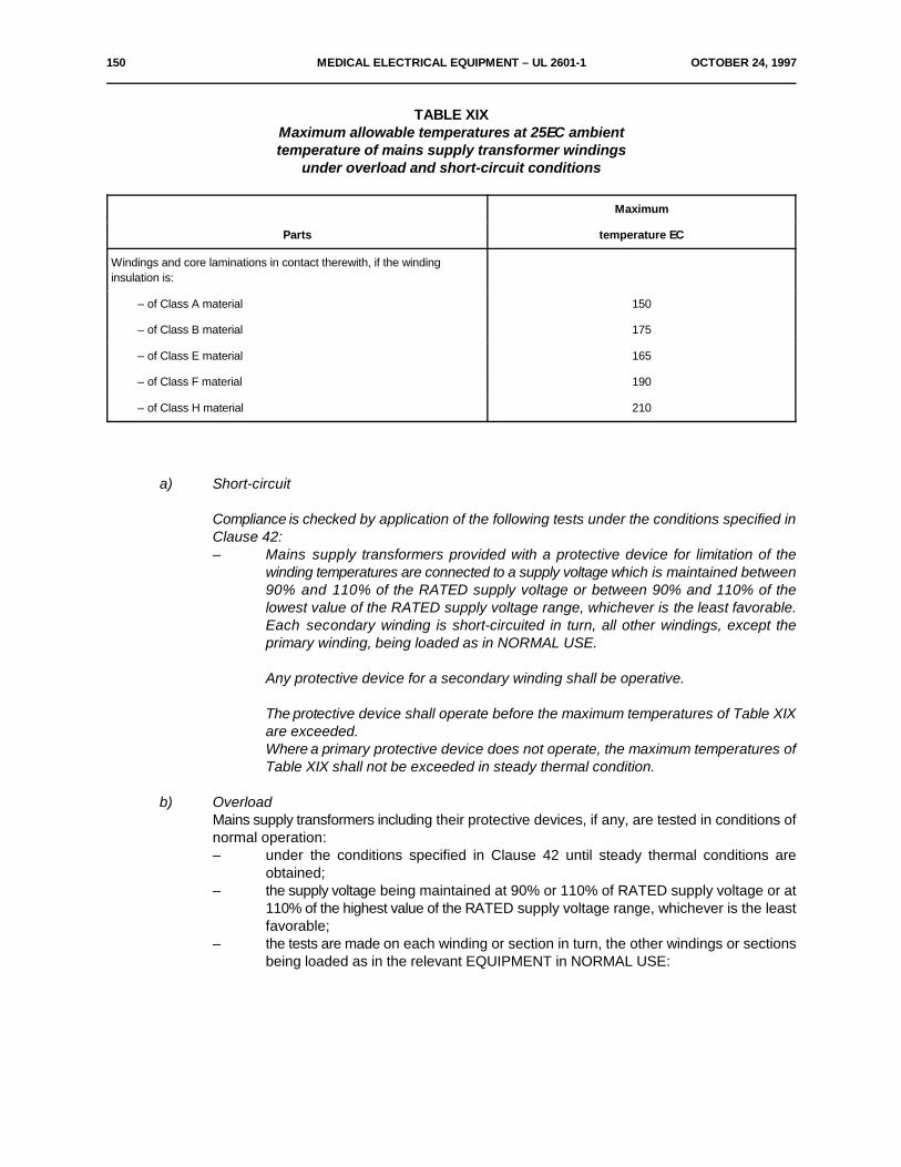
150 MEDICAL ELECTRICAL EQUIPMENT – UL 2601-1 OCTOBER 24, 1997
TABLE XIXMaximum allowable temperatures at 25EC ambienttemperature of mains supply transformer windings
under overload and short-circuit conditions
Maximum
Parts temperature EC
Windings and core laminations in contact therewith, if the windinginsulation is:
– of Class A material 150
– of Class B material 175
– of Class E material 165
– of Class F material 190
– of Class H material 210
a) Short-circuit
Compliance is checked by application of the following tests under the conditions specified inClause 42:– Mains supply transformers provided with a protective device for limitation of the
winding temperatures are connected to a supply voltage which is maintained between90% and 110% of the RATED supply voltage or between 90% and 110% of thelowest value of the RATED supply voltage range, whichever is the least favorable.Each secondary winding is short-circuited in turn, all other windings, except theprimary winding, being loaded as in NORMAL USE.
Any protective device for a secondary winding shall be operative.
The protective device shall operate before the maximum temperatures of Table XIXare exceeded.Where a primary protective device does not operate, the maximum temperatures ofTable XIX shall not be exceeded in steady thermal condition.
b) OverloadMains supply transformers including their protective devices, if any, are tested in conditions ofnormal operation:– under the conditions specified in Clause 42 until steady thermal conditions are
obtained;– the supply voltage being maintained at 90% or 110% of RATED supply voltage or at
110% of the highest value of the RATED supply voltage range, whichever is the leastfavorable;
– the tests are made on each winding or section in turn, the other windings or sectionsbeing loaded as in the relevant EQUIPMENT in NORMAL USE:
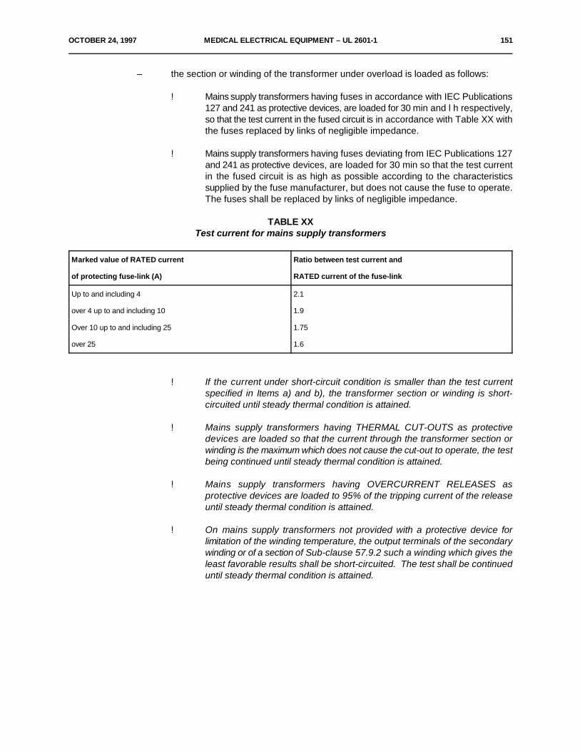
OCTOBER 24, 1997 MEDICAL ELECTRICAL EQUIPMENT – UL 2601-1 151
– the section or winding of the transformer under overload is loaded as follows:
! Mains supply transformers having fuses in accordance with IEC Publications127 and 241 as protective devices, are loaded for 30 min and l h respectively,so that the test current in the fused circuit is in accordance with Table XX withthe fuses replaced by links of negligible impedance.
! Mains supply transformers having fuses deviating from IEC Publications 127and 241 as protective devices, are loaded for 30 min so that the test currentin the fused circuit is as high as possible according to the characteristicssupplied by the fuse manufacturer, but does not cause the fuse to operate.The fuses shall be replaced by links of negligible impedance.
TABLE XXTest current for mains supply transformers
Marked value of RATED current Ratio between test current and
of protecting fuse-link (A) RATED current of the fuse-link
Up to and including 4 2.1
over 4 up to and including 10 1.9
Over 10 up to and including 25 1.75
over 25 1.6
! If the current under short-circuit condition is smaller than the test currentspecified in Items a) and b), the transformer section or winding is short-circuited until steady thermal condition is attained.
! Mains supply transformers having THERMAL CUT-OUTS as protectivedevices are loaded so that the current through the transformer section orwinding is the maximum which does not cause the cut-out to operate, the testbeing continued until steady thermal condition is attained.
! Mains supply transformers having OVERCURRENT RELEASES asprotective devices are loaded to 95% of the tripping current of the releaseuntil steady thermal condition is attained.
! On mains supply transformers not provided with a protective device forlimitation of the winding temperature, the output terminals of the secondarywinding or of a section of Sub-clause 57.9.2 such a winding which gives theleast favorable results shall be short-circuited. The test shall be continueduntil steady thermal condition is attained.
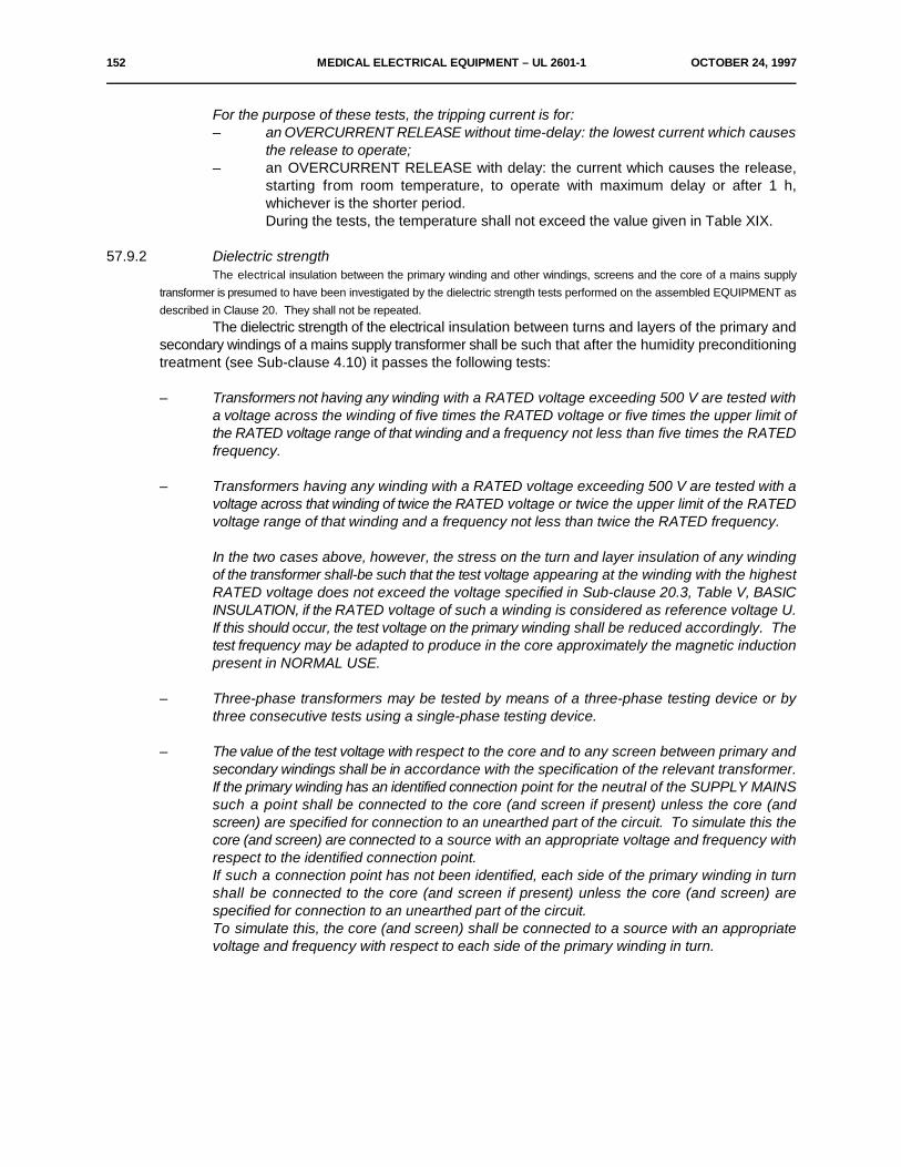
152 MEDICAL ELECTRICAL EQUIPMENT – UL 2601-1 OCTOBER 24, 1997
For the purpose of these tests, the tripping current is for:– an OVERCURRENT RELEASE without time-delay: the lowest current which causes
the release to operate;– an OVERCURRENT RELEASE with delay: the current which causes the release,
starting from room temperature, to operate with maximum delay or after 1 h,whichever is the shorter period.During the tests, the temperature shall not exceed the value given in Table XIX.
57.9.2 Dielectric strengthThe electrical insulation between the primary winding and other windings, screens and the core of a mains supply
transformer is presumed to have been investigated by the dielectric strength tests performed on the assembled EQUIPMENT asdescribed in Clause 20. They shall not be repeated.
The dielectric strength of the electrical insulation between turns and layers of the primary andsecondary windings of a mains supply transformer shall be such that after the humidity preconditioningtreatment (see Sub-clause 4.10) it passes the following tests:
– Transformers not having any winding with a RATED voltage exceeding 500 V are tested witha voltage across the winding of five times the RATED voltage or five times the upper limit ofthe RATED voltage range of that winding and a frequency not less than five times the RATEDfrequency.
– Transformers having any winding with a RATED voltage exceeding 500 V are tested with avoltage across that winding of twice the RATED voltage or twice the upper limit of the RATEDvoltage range of that winding and a frequency not less than twice the RATED frequency.
In the two cases above, however, the stress on the turn and layer insulation of any windingof the transformer shall-be such that the test voltage appearing at the winding with the highestRATED voltage does not exceed the voltage specified in Sub-clause 20.3, Table V, BASICINSULATION, if the RATED voltage of such a winding is considered as reference voltage U.If this should occur, the test voltage on the primary winding shall be reduced accordingly. Thetest frequency may be adapted to produce in the core approximately the magnetic inductionpresent in NORMAL USE.
– Three-phase transformers may be tested by means of a three-phase testing device or bythree consecutive tests using a single-phase testing device.
– The value of the test voltage with respect to the core and to any screen between primary andsecondary windings shall be in accordance with the specification of the relevant transformer.If the primary winding has an identified connection point for the neutral of the SUPPLY MAINSsuch a point shall be connected to the core (and screen if present) unless the core (andscreen) are specified for connection to an unearthed part of the circuit. To simulate this thecore (and screen) are connected to a source with an appropriate voltage and frequency withrespect to the identified connection point.If such a connection point has not been identified, each side of the primary winding in turnshall be connected to the core (and screen if present) unless the core (and screen) arespecified for connection to an unearthed part of the circuit.To simulate this, the core (and screen) shall be connected to a source with an appropriatevoltage and frequency with respect to each side of the primary winding in turn.
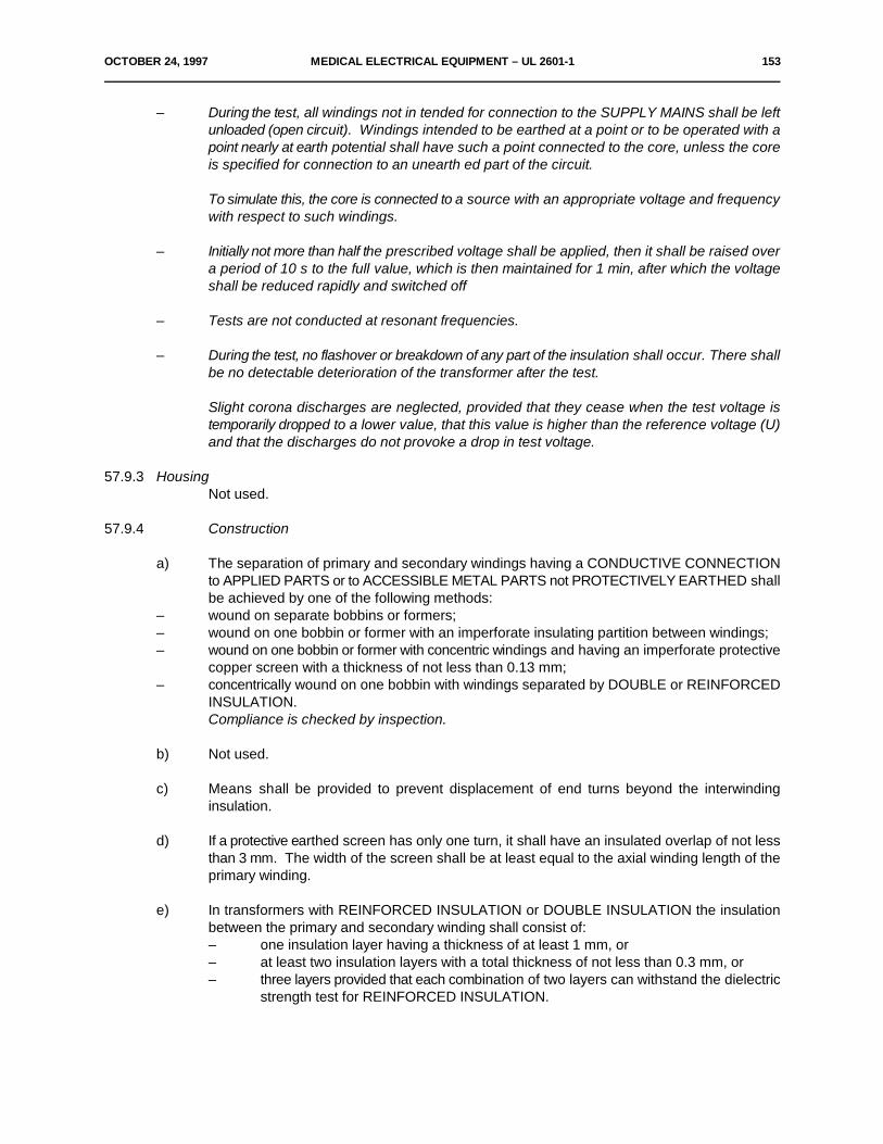
OCTOBER 24, 1997 MEDICAL ELECTRICAL EQUIPMENT – UL 2601-1 153
– During the test, all windings not in tended for connection to the SUPPLY MAINS shall be leftunloaded (open circuit). Windings intended to be earthed at a point or to be operated with apoint nearly at earth potential shall have such a point connected to the core, unless the coreis specified for connection to an unearth ed part of the circuit.
To simulate this, the core is connected to a source with an appropriate voltage and frequencywith respect to such windings.
– Initially not more than half the prescribed voltage shall be applied, then it shall be raised overa period of 10 s to the full value, which is then maintained for 1 min, after which the voltageshall be reduced rapidly and switched off
– Tests are not conducted at resonant frequencies.
– During the test, no flashover or breakdown of any part of the insulation shall occur. There shallbe no detectable deterioration of the transformer after the test.
Slight corona discharges are neglected, provided that they cease when the test voltage istemporarily dropped to a lower value, that this value is higher than the reference voltage (U)and that the discharges do not provoke a drop in test voltage.
57.9.3 HousingNot used.
57.9.4 Construction
a) The separation of primary and secondary windings having a CONDUCTIVE CONNECTIONto APPLIED PARTS or to ACCESSIBLE METAL PARTS not PROTECTIVELY EARTHED shallbe achieved by one of the following methods:
– wound on separate bobbins or formers;– wound on one bobbin or former with an imperforate insulating partition between windings;– wound on one bobbin or former with concentric windings and having an imperforate protective
copper screen with a thickness of not less than 0.13 mm;– concentrically wound on one bobbin with windings separated by DOUBLE or REINFORCED
INSULATION.Compliance is checked by inspection.
b) Not used.
c) Means shall be provided to prevent displacement of end turns beyond the interwindinginsulation.
d) If a protective earthed screen has only one turn, it shall have an insulated overlap of not lessthan 3 mm. The width of the screen shall be at least equal to the axial winding length of theprimary winding.
e) In transformers with REINFORCED INSULATION or DOUBLE INSULATION the insulationbetween the primary and secondary winding shall consist of:– one insulation layer having a thickness of at least 1 mm, or– at least two insulation layers with a total thickness of not less than 0.3 mm, or– three layers provided that each combination of two layers can withstand the dielectric
strength test for REINFORCED INSULATION.

154 MEDICAL ELECTRICAL EQUIPMENT – UL 2601-1 OCTOBER 24, 1997
f) For transformers complying with Sub-clause 57.9.4a) the CREEPAGE DISTANCES betweenthe primary and secondary windings shall comply with the requirements for REINFORCEDINSULATION (A-e, Table XX, Sub-clause 57.10) with the following allowances:– enamel or lacquer of winding wires are considered as contributing 1 mm each to
these CREEPAGE DISTANCES.– CREEPAGE DISTANCES are measured through the joint between two parts of an
insulation barrier, except when:! either the two parts forming the joint are bonded by heat sealing or other
similar means at the place where this is of importance;! or the joint is completely filled with adhesive at the necessary places and the
adhesive bonds to the surfaces of the insulating barrier so that humiditycannot be sucked into the joint.
– CREEPAGE DISTANCES within molded transformers are considered not to exist ifit can be shown that no gas bubbles are present and the thickness of the insulationbetween enamelled or lacquered primary and secondary windings is at least 1 mmfor reference voltages U not exceeding 250 V and increased proportionally for higherreference voltages.
g) The exit of the wires from the internal windings of toroidal transformers shall be provided withdouble sleeving complying with the requirements for DOUBLE INSULATION and having a totalwall thickness of at least 0.3 mm, extending at least 20 mm outside the winding.
Compliance with the requirements of Sub-clauses 57.9.4c) through 5 7.9.4g) ischecked by inspection.
57.10 CREEPAGE DISTANCES and AIR CLEARANCES
*a) Values
– CREEPAGE DISTANCES and AIR CLEARANCES shall comply with at least thevalues of Table XVI.For a number of insulations Sub-clauses 20.1 and 20.2 apply.
– The value of the reference voltage (U) is as given in Sub-clause 20.3. In case thereference voltage has a value between those given in Table XVI, the higher of the twovalues shall be applied.Values for reference voltages above 1000 V a.c. or 1200 V d.c. are under consideration.
– For slot insulation of motors a reduction to 50% of the values of Table XVI forCREEPAGE DISTANCES shall be allowed, with a minimum of 2 mm at 250 V.
*b) Application
– For insulation in the MAINS PART between parts of opposite polarity (see Sub-clause20.1 A-f) the minimum CREEPAGE DISTANCES and AIR CLEARANCES are notrequired if short-circuiting of each single one of these CREEPAGE DISTANCES andAIR CLEARANCES in turn does not produce a SAFETY HAZARD.
Operation of a protective device shall not be considered as a SAFETY HAZARD.

OCTOBER 24, 1997 MEDICAL ELECTRICAL EQUIPMENT – UL 2601-1 155
– The contribution to the CREEPAGE DISTANCES of any groove or air gap less than1 mm wide shall be limited to its width (see Figures 39 through 47).The AIR CLEARANCES required between LIVE parts shall not apply to the air gapbetween the switching contacts of THERMOSTATS, THERMAL CUT-OUTS,OVERCURRENT RELEASES, switches of microgap construction and the like, or tothe air gap between the current-carrying parts of such devices where the clearancevaries with the movement of the contacts and where adequacy of ratings has beenproved.
– When assessing CREEPAGE DISTANCES and AIR CLEARANCES, the effect ofinsulating linings of metal ENCLOSURES or covers shall be taken into consideration.
If the insulation on a conductor is not at least electrically equivalent to that of theindividual conductors of flexible cords, that conductor shall be considered to be a bareconductor and the insulation thickness shall be regarded as an AIR CLEARANCE.See also Sub-clause 57.8a.
– AIR CLEARANCE alone is only acceptable for isolation between LIVE parts andAPPLIED PARTS and ACCESSIBLE PARTS not PROTECTIVELY EARTHED if therelative positioning is such that the relevant parts are rigid and located by moldingsor the design is otherwise such that there is no likelihood of a distance being reducedby deformation or movement of the parts.Where limited movement of one of the relevant parts is normal or likely, this shall betaken into account when computing the minimum clearance.
*c) Not used.
*d) Measurement of CREEPAGE DISTANCES and AIR CLEARANCESCompliance is checked by measurement taking into account the rules in Figures 39 through47.For EQUIPMENT provided with an APPLIANCE INLET, the measurements are made with anappropriate connector inserted. For other EQUIPMENT incorporating POWER SUPPLYCORDS, they are made with supply conductors of the largest cross-sectional area specifiedand also without conductors.Movable parts are placed in the least favorable position; nuts and screws with non-circularheads are tightened in the least favorable position.AIR CLEARANCES and CREEPAGE DISTANCES between terminals and ACCESSIBLEPARTS are also measured with the screws or nuts unscrewed as far as possible, and the AIRCLEARANCES shall then be not less than 50% of the values shown in Table XVI.
CREEPAGE DISTANCES and AIR CLEARANCES through slots or openings in external partsof insulating material are measured to metal foil in contact with the accessible surface. Forthe purpose of this sub-clause accessible surfaces of insulating material are treated as thoughthey were covered with a layer of metal foil, foil being stretched across any openings, butpressed into corners with the standard test finger of Figure 7.
If necessary, a force is applied to any point on bare conductors and to the outside of metalENCLOSURES in an endeavor to reduce the CREEPAGE DISTANCES and AIRCLEARANCES while taking the measurements.The force is applied by means of a standard test finger having a tip as shown in Figure 7 andhaving a value of:
2 N for bare conductors;30 N for ENCLOSURES.
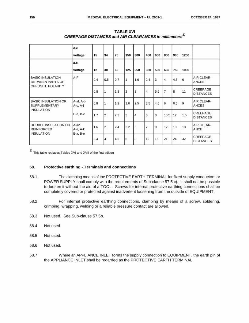
156 MEDICAL ELECTRICAL EQUIPMENT – UL 2601-1 OCTOBER 24, 1997
TABLE XVICREEPAGE DISTANCES and AIR CLEARANCES in millimeters1)
d.c
voltage 15 34 75 150 300 450 600 800 900 1200
a.c.
voltage 12 30 60 125 250 380 500 660 750 1000
BASIC INSULATION A-F AIR CLEAR-BETWEEN PARTS OF ANCESOPPOSITE POLARITY
0.4 0.5 0.7 1 1.6 2.4 3 4 4.5 6
0.8 1 1.3 2 3 4 5.5 7 8 11CREEPAGEDISTANCES
BASIC INSULATION OR A-al, A-b AIR CLEAR-SUPPLEMENTARY A-c, A-j ANCESINSULATION
B-d, B-c
0.8 1 1.2 1.6 2.5 3.5 4.5 6 6.5 9
1.7 2 2.3 3 4 6 8 10.5 12 1.6CREEPAGEDISTANCES
DOUBLE INSULATION OR A-a2 AIR CLEAR-REINFORCED A-e, A-k ANCEINSULATION B-a, B-e
1.6 2 2.4 3.2 5 7 9 12 13 18
3.4 4 4.6 6 8 12 16 21 24 32CREEPAGEDISTANCES
This table replaces Tables XVI and XVII of the first edition1)
58. Protective earthing - Terminals and connections
58.1 The clamping means of the PROTECTIVE EARTH TERMINAL for fixed supply conductors orPOWER SUPPLY shall comply with the requirements of Sub-clause 57.5 c). It shall not be possibleto loosen it without the aid of a TOOL. Screws for internal protective earthing connections shall becompletely covered or protected against inadvertent loosening from the outside of EQUIPMENT.
58.2 For internal protective earthing connections, clamping by means of a screw, soldering,crimping, wrapping, welding or a reliable pressure contact are allowed.
58.3 Not used. See Sub-clause 57.5b.
58.4 Not used.
58.5 Not used.
58.6 Not used.
58.7 Where an APPLIANCE INLET forms the supply connection to EQUIPMENT, the earth pin ofthe APPLIANCE INLET shall be regarded as the PROTECTIVE EARTH TERMINAL.

OCTOBER 24, 1997 MEDICAL ELECTRICAL EQUIPMENT – UL 2601-1 157
58.8 The PROTECTIVE EARTH TERMINAL shall not be used for the mechanical connectionbetween different parts of the EQUIPMENT or the fixing of any component not related to protectiveearthing or functional earthing.
58.9 Protective earth connection
Where the connection between mains supply conductors and EQUIPMENT or betweenseparated parts of EQUIPMENT which can be operated by the OPERATOR is made via a plug andsocket device, the protective earth connection shall be made before and interrupted after the supplyconnections are made or interrupted. This applies also where interchangeable parts are connectedto protective earth. See also Sub-clauses 57.1, 57.2 and 57.3.
Compliance with the requirements of Clause 58 is checked by inspection of materials andconstruction, by manual tests and by the test of Sub-clause 57.5.
59. Construction and layout
59.1 Internal wiringFor fixing of wiring in the APPLIED PART and the MAINS PART, see Sub-clause 56.1f.
a) Mechanical protection– Cables and wiring shall be adequately protected against contact with a moving part
or from friction at edges or sharp corners, if there is a relative movement between thepart and cords or wiring.
– Wiring having BASIC INSULATION only shall be protected by additional fixed sleevingor by other similar means where it is in direct contact with metal parts and where suchwiring is subject to a relative movement in NORMAL USE during which it is in directcontact with metal parts.
– EQUIPMENT shall be so designed that wiring, cord forms or components are notlikely to be damaged in the normal process of assembly or replacement of covers orthe opening or closing of inspection doors.
Compliance is checked by inspection and, where appropriate, by manual test.
b) BendingGuiding rollers of leads shall be constructed in such a manner that movable leads in NORMALUSE are not bent round a radius of less than five times the outer diameter of the leadconcerned.Compliance is checked by inspection and measurement of the relevant dimensions.
c) Insulation– If insulating sleeving is needed on internal wiring, it shall be adequately secured.
Sleeving is regarded as adequately secured if it can only be removed by breaking orcutting or if it is secured at both ends.
– Inside EQUIPMENT the sheath of a flexible cord shall be used as SUPPLEMENTARYINSULATION only where it is not subject to undue mechanical or thermal stressesand if its insulation properties are not less than those specified in IEC Publications 227or 245.
– Insulated conductors which in NORMAL USE are subject to temperatures exceeding75EC shall have an insulation of heat-resistant material if compliance with thisStandard is likely to be impaired by deterioration of the insulation.
Compliance is checked by inspection and, if necessary, by special tests. Temperatures shallbe determined as indicated in Clause 42.
158 MEDICAL ELECTRICAL EQUIPMENT – UL 2601-1 OCTOBER 24, 1997
d) MaterialsAluminum wires of less than 16 mm cross-section shall not be used.2
Compliance is checked by inspection.
*e) Separation of circuitsNot used. See Clause 17.
f) Applicable requirementsConnecting cords between EQUIPMENT parts, e.g. parts of an X-ray installation or a PATIENTmonitoring installation or a data-processing installation or combinations thereof shall beconsidered as belonging to the EQUIPMENT and not be subject to requirements for wiring ofelectrical installations (in hospitals or otherwise).
Compliance is checked by application of the relevant tests of this Standard.
59.2 InsulationThis sub-clause refers to parts of EQUIPMENT other than wire insulation which is covered in
Sub-clause 59.1c.
a) FixingNot used.
*b) Mechanical strength and resistance to heat and fireThe insulating characteristics, mechanical strength and resistance to heat and fire shall beretained by all types of insulation, including insulating partition walls, even in the case ofextended use.
Compliance is established by inspection and, if necessary, in conjunction with the followingtests:
– resistance to moisture, etc. (see Clause 44);– dielectric strength (see Clause 20);– mechanical strength-(see Clause 21).
Resistance to heat is established by the following tests which need not be performed ifsatisfactory evidence of compliance is provided:
1) For parts of the ENCLOSURE and other external insulating parts, the deteriorationof which could influence the safety of the EQUIPMENT, by the ball-pressure test:ENCLOSURES and other external parts of insulating material, except the insulationof flexible cords, are subjected to a ball-pressure test using the test apparatus shownin Figure 48. The surface of the part to be tested is placed in the horizontal positionand a steel ball of 5 mm diameter is pressed against the surface with a force of 20 N.The test is made in a heating cabinet at a temperature of 75EC ±2EC or at atemperature of 40EC ±2EC plus the temperature rise of the relevant part of insulatingmaterial measured during the test of Clause 42, whichever is the higher.
OCTOBER 24, 1997 MEDICAL ELECTRICAL EQUIPMENT – UL 2601-1 159
The ball is withdrawn after 1 h and the diameter of the impression made by the ballis measured. It shall be not greater than 2 mm. The test is not made on parts ofceramic material.
2) For parts of insulating material which support uninsulated parts of the MAINS PART,the deterioration of which could influence the safety of the EQUIPMENT, by the ball-pressure test:A test is made as described in Item 1, but at a temperature of 125EC ±2EC or at atemperature of 40EC ±2EC plus the temperature rise which was determined duringthe test of Clause 42 of the relevant part, whichever is the higher.
The test is not made on parts of ceramic material, insulating parts of commutators, brush-capsand the like, on coil formers not used as REINFORCED INSULATION and the insulation ofcords.
Note – For SUPPLEMENTARY INSULATION and REINFORCED INSULATION of thermoplastic materials, see also Sub-clause52.4.1.
c) ProtectionBASIC INSULATION, SUPPLEMENTARY INSULATION and REINFORCED INSULATIONshall be so designed or protected that they are not likely to be impaired by deposition of dirtor by dust resulting from wear of parts within the EQUIPMENT to such an extent thatCREEPAGE DISTANCES and AIR CLEARANCES are reduced below the values specified inSub-clause 57.10.Ceramic material not tightly sintered, and the like, and beads alone shall not be used asSUPPLEMENTARY INSULATION or REINFORCED INSULATION.
Parts of natural or synthetic rubber used as SUPPLEMENTARY INSULATION in CLASS IIEQUIPMENT shall be resistant to ageing and be so arranged and dimensioned thatCREEPAGE DISTANCES are not reduced below the values specified in Sub-clause 57.10whatever cracks may occur.
Insulating material in which heating conductors are embedded shall be considered as BASICINSULATION and shall not be used as REINFORCED INSULATION.
Compliance is checked by inspection, by measurement and for rubber by the following test:
Parts of rubber are aged in an atmosphere of oxygen under pressure. The samples aresuspended freely in an oxygen cylinder, the effective capacity of the cylinder is at least tentimes the volume of the samples. The cylinder is filled with commercial oxygen not less than97% pure, to a pressure of 210 ±7 N/cm .2
The samples are kept in the cylinder at a temperature of 70EC ±2EC for 96 h. Immediatelyafterwards, they are taken out of the cylinder and left at room temperature for at least 16 h.After the test, the samples are examined and shall show no crack visible to the naked eye.
160 MEDICAL ELECTRICAL EQUIPMENT – UL 2601-1 OCTOBER 24, 1997
59.3 Excessive current and voltage protection
– See Sub-clause 57.6.
– An INTERNAL ELECTRICAL POWER SOURCE in EQUIPMENT shall be provided with anappropriately RATED device for protection against fire hazard caused by excessive currentsif the cross-sectional area and layout of the internal wiring or the rating of connectedcomponents may give rise to the occurrence of a fire hazard in case of a short circuit.Test under consideration.
– Fuse elements replaceable without opening the ENCLOSURE of the EQUIPMENT shall befully enclosed in a fuseholder. When fuse replacement can be carried out without the use ofa TOOL, uninsulated LIVE parts associated with the fuseholder shall be shielded to enablefuse replacement without a SAFETY HAZARD.
Compliance is checked by inspection and by the use of the standard test finger.
– Protective devices connected between an F-TYPE APPLIED PART and the ENCLOSURE forthe purpose of providing protection against excessive voltages shall not operate below 500 Vr.m.s.
Compliance is checked by testing the operating-voltage of the protective devices.
– For THERMAL CUT-OUTS and OVER-CURRENT RELEASES see Sub-clause 56.6a).
59.4 Oil containers
– Oil containers in PORTABLE EQUIPMENT shall be adequately sealed to prevent loss of oilin any position. The container design shall allow for the expansion of the oil.
Oil containers in MOBILE EQUIPMENT shall be sealed to prevent the loss of oil duringtransport but may be fitted with a pressure-release device which can operate during NORMALUSE.
– Partially sealed oil-filled EQUIPMENT or EQUIPMENT parts shall be provided with means forchecking the oil level.
Compliance is checked by inspection of EQUIPMENT, technical description and by manual test.
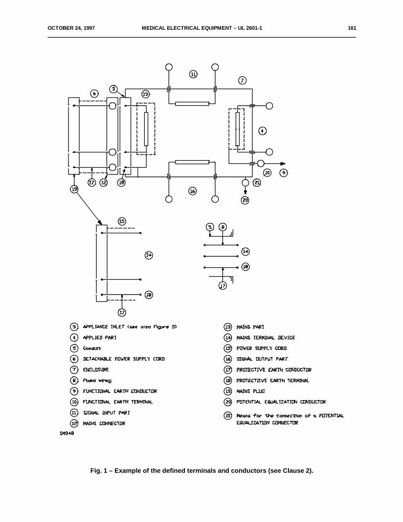
OCTOBER 24, 1997 MEDICAL ELECTRICAL EQUIPMENT – UL 2601-1 161
Fig. 1 – Example of the defined terminals and conductors (see Clause 2).
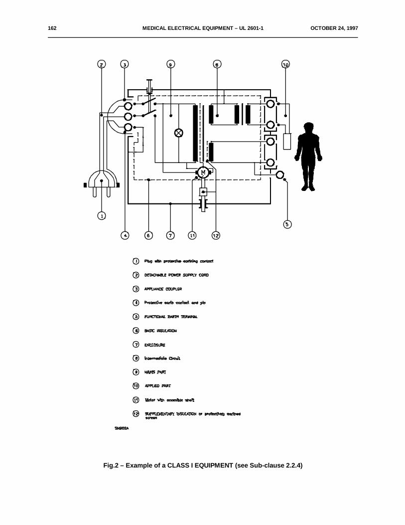
162 MEDICAL ELECTRICAL EQUIPMENT – UL 2601-1 OCTOBER 24, 1997
Fig.2 – Example of a CLASS I EQUIPMENT (see Sub-clause 2.2.4)
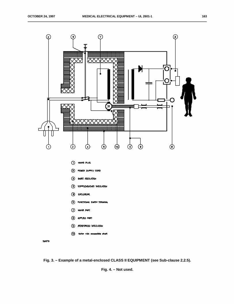
OCTOBER 24, 1997 MEDICAL ELECTRICAL EQUIPMENT – UL 2601-1 163
Fig. 3. – Example of a metal-enclosed CLASS II EQUIPMENT (see Sub-clause 2.2.5).
Fig. 4. – Not used.
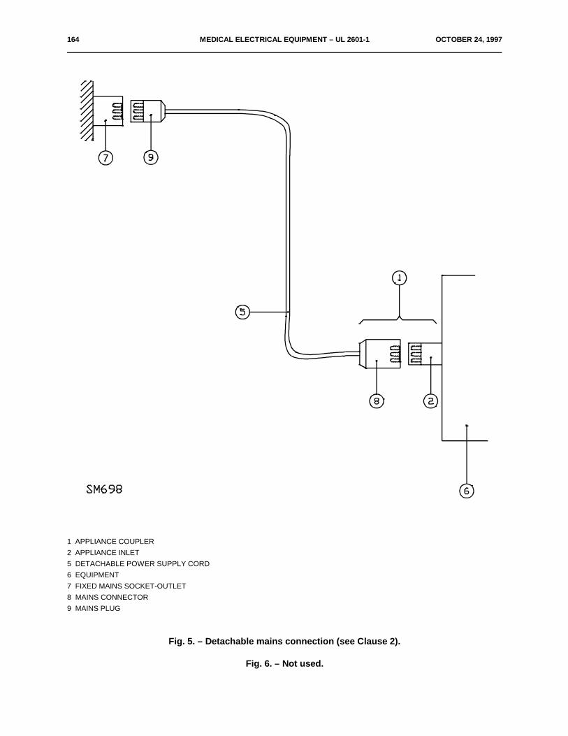
164 MEDICAL ELECTRICAL EQUIPMENT – UL 2601-1 OCTOBER 24, 1997
1 APPLIANCE COUPLER2 APPLIANCE INLET5 DETACHABLE POWER SUPPLY CORD6 EQUIPMENT7 FIXED MAINS SOCKET-OUTLET8 MAINS CONNECTOR9 MAINS PLUG
Fig. 5. – Detachable mains connection (see Clause 2).
Fig. 6. – Not used.

OCTOBER 24, 1997 MEDICAL ELECTRICAL EQUIPMENT – UL 2601-1 165
Linear dimensions in millimetresTolerances on dimensions without specific tolerance:
on angles: + 0–10E
on linear dimensions: up to 25 mm:+0–0.05
over 25 mm: ±0.2
Material of parts 1, 2 and 3 metal (e.g. heat-treated steel)
Both joints of this finger may be bent through an angleof 90 but in one and the same direction only.
+10E0
Using the pin and groove solutions is only one of thepossible approaches in order to limit the bending angleto 90E. For this reason dimensions and tolerances ofthese details are not given in the drawing. The actual de-sign must ensure a 90E bending angle with a 0 to + 10Etolerance.
Fig. 7. – Standard test finger (see Clause 16).
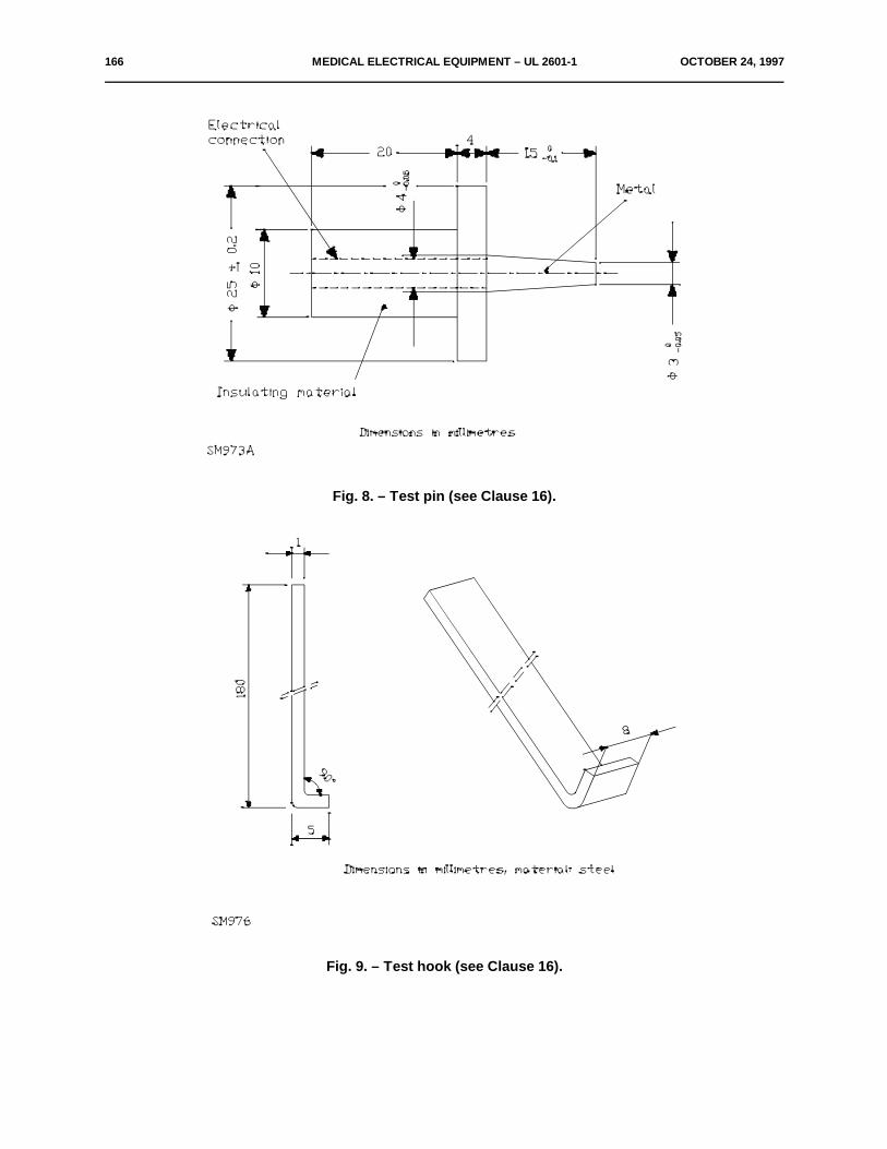
166 MEDICAL ELECTRICAL EQUIPMENT – UL 2601-1 OCTOBER 24, 1997
Fig. 8. – Test pin (see Clause 16).
Fig. 9. – Test hook (see Clause 16).
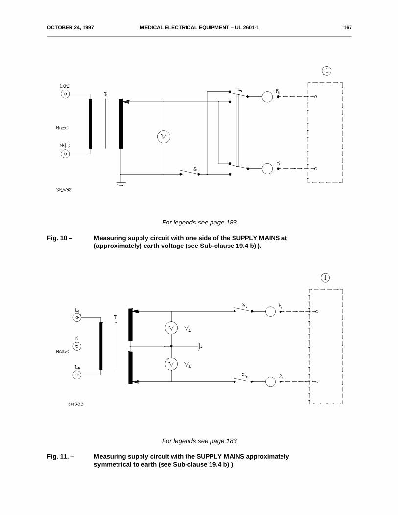
OCTOBER 24, 1997 MEDICAL ELECTRICAL EQUIPMENT – UL 2601-1 167
For legends see page 183
Fig. 10 – Measuring supply circuit with one side of the SUPPLY MAINS at(approximately) earth voltage (see Sub-clause 19.4 b) ).
For legends see page 183
Fig. 11. – Measuring supply circuit with the SUPPLY MAINS approximatelysymmetrical to earth (see Sub-clause 19.4 b) ).
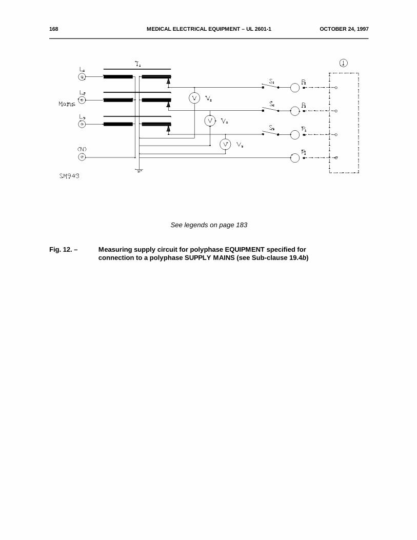
168 MEDICAL ELECTRICAL EQUIPMENT – UL 2601-1 OCTOBER 24, 1997
See legends on page 183
Fig. 12. – Measuring supply circuit for polyphase EQUIPMENT specified forconnection to a polyphase SUPPLY MAINS (see Sub-clause 19.4b)

OCTOBER 24, 1997 MEDICAL ELECTRICAL EQUIPMENT – UL 2601-1 169
See Legends on page 183
Fig. 13. – Measuring supply circuit for single-phase EQUIPMENT specified forconnection to apolyphase SUPPLY MAINS (see Sub-clause 19.4b).

170 MEDICAL ELECTRICAL EQUIPMENT – UL 2601-1 OCTOBER 24, 1997
See Legends on page 183
Fig. 14. – Measuring supply circuit for either EQUIPMENT supplied from a specified class I single-phase power supply or for EQUIPMENT supplied from a specified class II single-phasepower supply, not using in this case the protective earth connection and S (see Sub-8clause 19.4b).
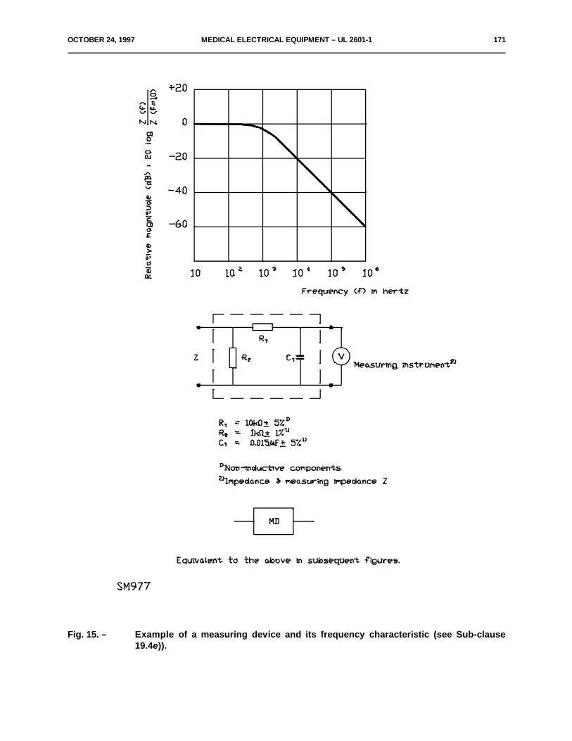
OCTOBER 24, 1997 MEDICAL ELECTRICAL EQUIPMENT – UL 2601-1 171
Fig. 15. – Example of a measuring device and its frequency characteristic (see Sub-clause19.4e)).
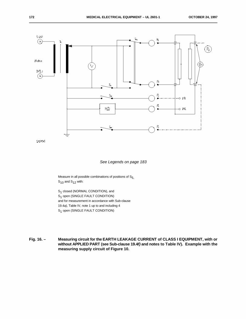
172 MEDICAL ELECTRICAL EQUIPMENT – UL 2601-1 OCTOBER 24, 1997
See Legends on page 183
Measure in all possible combinations of positions of S5,S and S with:10 12
S closed (NORMAL CONDITION), and1S open (SINGLE FAULT CONDITION)1and for measurement in accordance with Sub-clause19.4a), Table IV, note 1 up to and including 4S open (SINGLE FAULT CONDITION)1
Fig. 16. – Measuring circuit for the EARTH LEAKAGE CURRENT of CLASS I EQUIPMENT, with orwithout APPLIED PART (see Sub-clause 19.4f) and notes to Table IV). Example with themeasuring supply circuit of Figure 10.
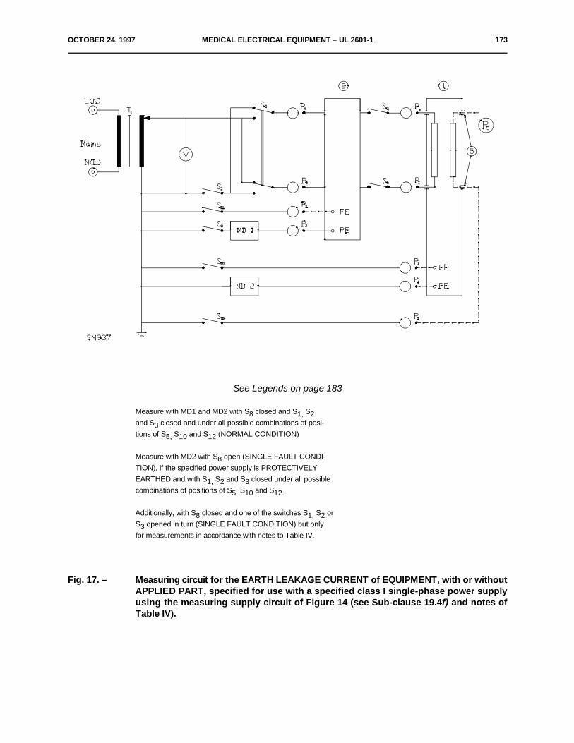
OCTOBER 24, 1997 MEDICAL ELECTRICAL EQUIPMENT – UL 2601-1 173
See Legends on page 183
Measure with MD1 and MD2 with S closed and S S8 1, 2and S closed and under all possible combinations of posi-3tions of S S and S (NORMAL CONDITION)5, 10 12
Measure with MD2 with S open (SINGLE FAULT CONDI-8TION), if the specified power supply is PROTECTIVELYEARTHED and with S S and S closed under all possible1, 2 3combinations of positions of S S and S5, 10 12.
Additionally, with S closed and one of the switches S S or8 1, 2S opened in turn (SINGLE FAULT CONDITION) but only3for measurements in accordance with notes to Table IV.
Fig. 17. – Measuring circuit for the EARTH LEAKAGE CURRENT of EQUIPMENT, with or withoutAPPLIED PART, specified for use with a specified class I single-phase power supplyusing the measuring supply circuit of Figure 14 (see Sub-clause 19.4f) and notes ofTable IV).
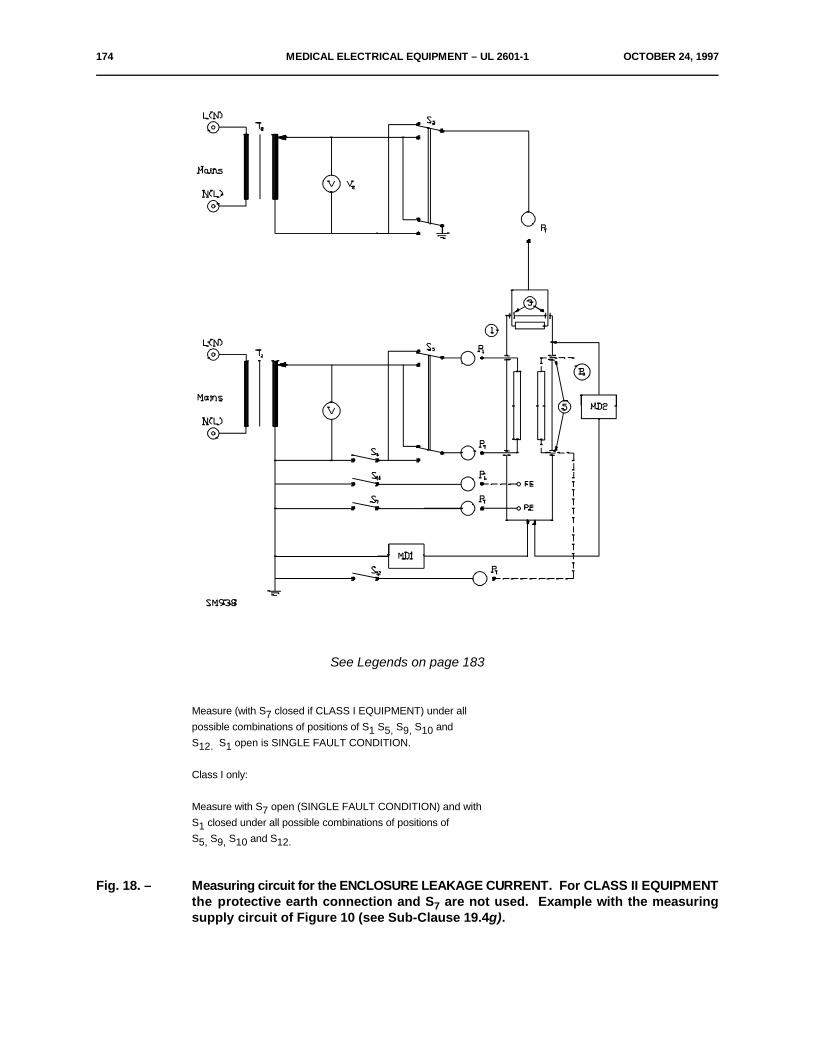
174 MEDICAL ELECTRICAL EQUIPMENT – UL 2601-1 OCTOBER 24, 1997
See Legends on page 183
Measure (with S closed if CLASS I EQUIPMENT) under all7possible combinations of positions of S S S S and1 5, 9, 10S S open is SINGLE FAULT CONDITION.12. 1
Class I only:
Measure with S open (SINGLE FAULT CONDITION) and with7S closed under all possible combinations of positions of1S S S and S5, 9, 10 12.
Fig. 18. – Measuring circuit for the ENCLOSURE LEAKAGE CURRENT. For CLASS II EQUIPMENTthe protective earth connection and S are not used. Example with the measuring7supply circuit of Figure 10 (see Sub-Clause 19.4g).

OCTOBER 24, 1997 MEDICAL ELECTRICAL EQUIPMENT – UL 2601-1 175
See Legends on page 183
Measure with MD1 and MD2 (with S closed if specified power supply is of class I) under all possible combinations of posi-8tions of S S S and S S open is SINGLE FAULT CONDITION.1, 5, 9 11. 1
Specified power supply of class I only:Measure with MD1 and MD2 with S open (SINGLE FAULT CONDITION) and with S closed under all possible combinations of7 1positions of S S and S5, 9 11.
Measure with MD3 and MD4 (with S closed if the EQUIPMENT itself is of CLASS I and with S closed if the specified power7 8supply is of class I) with:
! S S and S closed (NORMAL CONDITION) and1, 2 3! S or S or S open (SINGLE FAULT CONDITION) under all possible combinations of S and of S S S and S1 2 3 5 9, 10, 11 12.
Measure with MD3 and MD4 with either (SINGE FAULT CONDITION):
! S open (when the EQUIPMENT is of CLASS I) or7! S open (when the specified power supply is of class I) and with S S and S closed under all possible combinations of8 1, 2 3positions of S and of S S S and S5 9, 10, 11 12.
Fig. 19. – Measuring circuit for the ENCLOSURE LEAKAGE CURRENT of EQUIPMENT with orwithout APPLIED PART, intended only for use with a specified single-phase powersupply. For a specified single-phase supply circuit of Class II, the protective earthconnection and S are not used. Example with measuring supply circuit of Figure 147(see Sub-clause 19.4g).
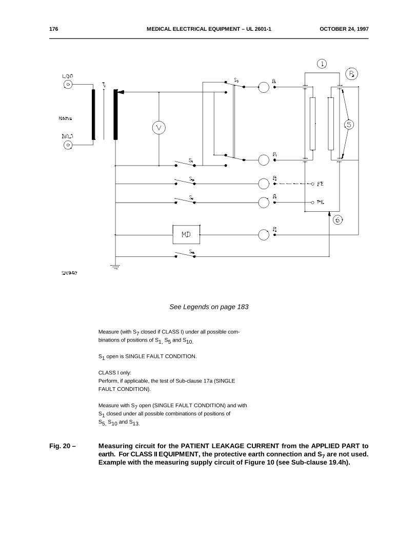
176 MEDICAL ELECTRICAL EQUIPMENT – UL 2601-1 OCTOBER 24, 1997
See Legends on page 183
Measure (with S closed if CLASS I) under all possible com-7binations of positions of S S and S1, 5 10.
S open is SINGLE FAULT CONDITION.1
CLASS I only:Perform, if applicable, the test of Sub-clause 17a (SINGLEFAULT CONDITION).
Measure with S open (SINGLE FAULT CONDITION) and with7S closed under all possible combinations of positions of1S S and S5, 10 13.
Fig. 20 – Measuring circuit for the PATIENT LEAKAGE CURRENT from the APPLIED PART toearth. For CLASS II EQUIPMENT, the protective earth connection and S are not used.7Example with the measuring supply circuit of Figure 10 (see Sub-clause 19.4h).
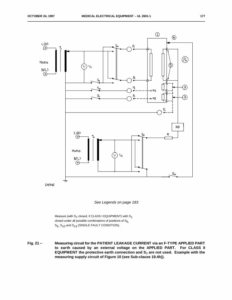
OCTOBER 24, 1997 MEDICAL ELECTRICAL EQUIPMENT – UL 2601-1 177
See Legends on page 183
Measure (with S closed, if CLASS I EQUIPMENT) with S7 1closed under all possible combinations of positions of S5,S S and S (SINGLE FAULT CONDITION).9, 10 13
Fig. 21 – Measuring circuit for the PATIENT LEAKAGE CURRENT via an F-TYPE APPLIED PARTto earth caused by an external voltage on the APPLIED PART. For CLASS IIEQUIPMENT the protective earth connection and S are not used. Example with the7measuring supply circuit of Figure 10 (see Sub-clause 19.4h)).
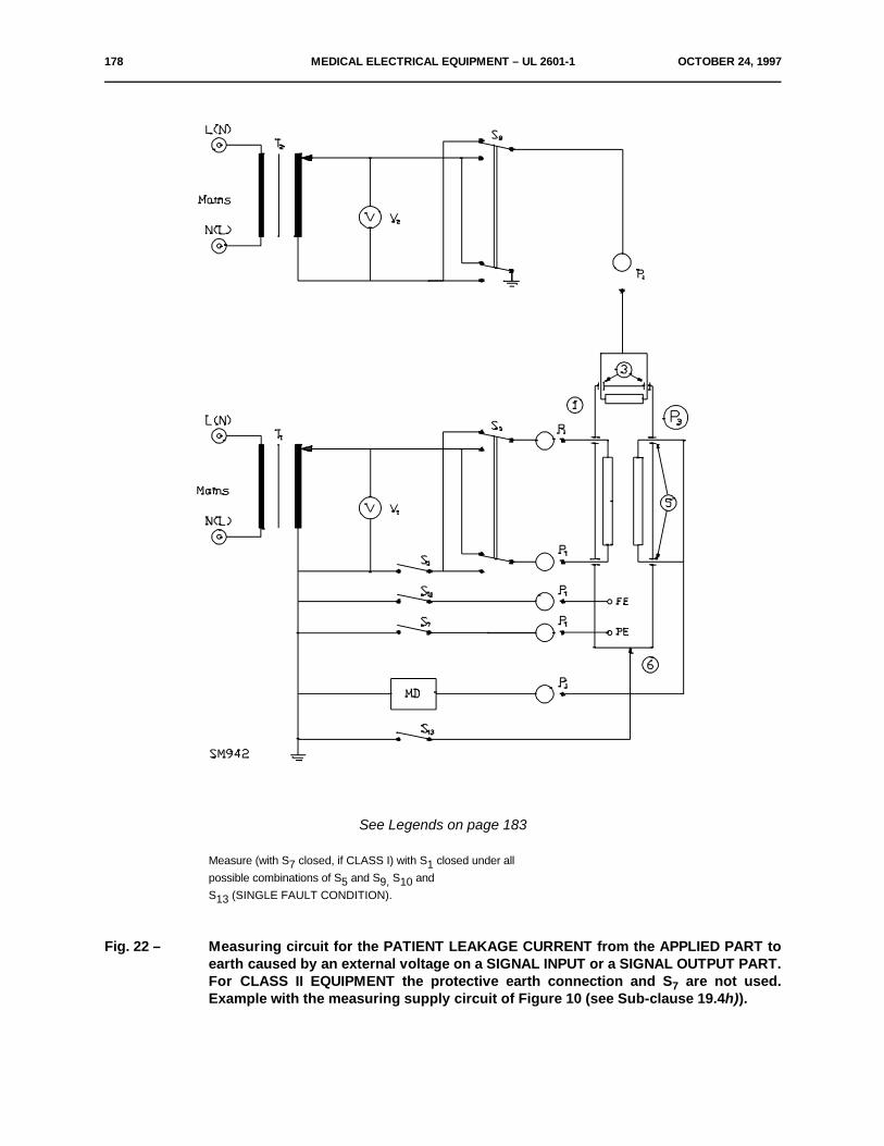
178 MEDICAL ELECTRICAL EQUIPMENT – UL 2601-1 OCTOBER 24, 1997
See Legends on page 183
Measure (with S closed, if CLASS I) with S closed under all7 1possible combinations of S and S S and5 9, 10S (SINGLE FAULT CONDITION).13
Fig. 22 – Measuring circuit for the PATIENT LEAKAGE CURRENT from the APPLIED PART toearth caused by an external voltage on a SIGNAL INPUT or a SIGNAL OUTPUT PART.For CLASS II EQUIPMENT the protective earth connection and S are not used.7Example with the measuring supply circuit of Figure 10 (see Sub-clause 19.4h)).
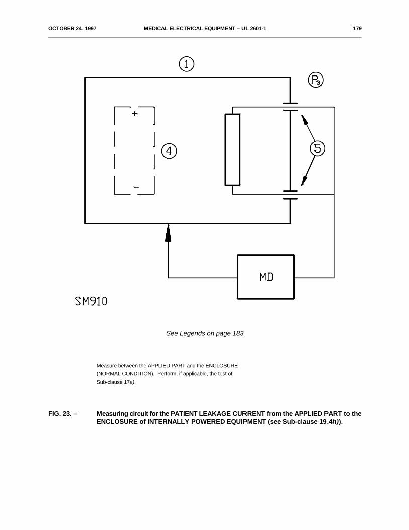
OCTOBER 24, 1997 MEDICAL ELECTRICAL EQUIPMENT – UL 2601-1 179
See Legends on page 183
Measure between the APPLIED PART and the ENCLOSURE(NORMAL CONDITION). Perform, if applicable, the test ofSub-clause 17a).
FIG. 23. – Measuring circuit for the PATIENT LEAKAGE CURRENT from the APPLIED PART to theENCLOSURE of INTERNALLY POWERED EQUIPMENT (see Sub-clause 19.4h)).

180 MEDICAL ELECTRICAL EQUIPMENT – UL 2601-1 OCTOBER 24, 1997
See Legends on page 183
Fig. 24. – Measuring circuit for the PATIENT LEAKAGE CURRENT via an F-TYPE APPLIED PARTto the ENCLOSURE of INTERNALLY POWERED EQUIPMENT (see Sub-clause 19.4h)).
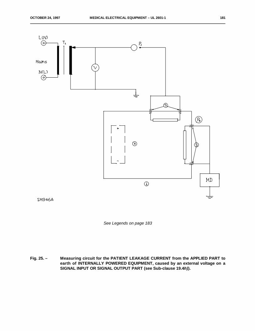
OCTOBER 24, 1997 MEDICAL ELECTRICAL EQUIPMENT – UL 2601-1 181
See Legends on page 183
Fig. 25. – Measuring circuit for the PATIENT LEAKAGE CURRENT from the APPLIED PART toearth of INTERNALLY POWERED EQUIPMENT, caused by an external voltage on aSIGNAL INPUT OR SIGNAL OUTPUT PART (see Sub-clause 19.4h)).
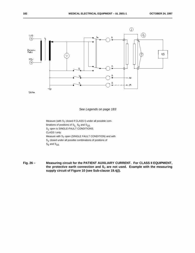
182 MEDICAL ELECTRICAL EQUIPMENT – UL 2601-1 OCTOBER 24, 1997
See Legends on page 183
Measure (with S closed if CLASS I) under all possible com-7binations of positions of S S and S1, 5 10.S open is SINGLE-FAULT CONDITIONS.1CLASS I only:Measure with S open (SINGLE FAULT CONDITION) and with7S closed under all possibe combinations of positions of1S and S5 10.
Fig. 26 – Measuring circuit for the PATIENT AUXILIARY CURRENT. For CLASS II EQUIPMENT,the protective earth connection and S are not used. Example with the measuring7supply circuit of Figure 10 (see Sub-clause 19.4j)).
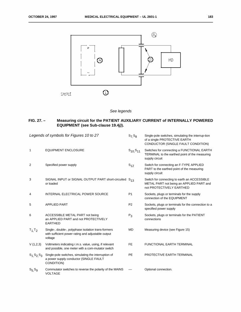
OCTOBER 24, 1997 MEDICAL ELECTRICAL EQUIPMENT – UL 2601-1 183
See legends
FIG. 27. – Measuring circuit for the PATIENT AUXILIARY CURRENT of INTERNALLY POWEREDEQUIPMENT (see Sub-clause 19.4j)).
Legends of symbols for Figures 10 to 27 S S Single-pole switches, simulating the interrup-tion7, 8of a single PROTECTIVE EARTHCONDUCTOR (SINGLE FAULT CONDITION)
1 EQUIPMENT ENCLOSURE S S Switches for connecting a FUNCTIONAL EARTH10, 11TERMINAL to the earthed point of the measuringsupply circuit
2 Specified power supply S Switch for connecting an F-TYPE APPLIED12PART to the earthed point of the measuringsupply circuit
3 SIGNAL INPUT or SIGNAL OUTPUT PART short-circuited S Switch for connecting to earth an ACCESSIBLEor loaded METAL PART not being an APPLIED PART and
13
not PROTECTIVELY EARTHED
4 INTERNAL ELECTRICAL POWER SOURCE P1 Sockets, plugs or terminals for the supplyconnection of the EQUIPMENT
5 APPLIED PART P2 Sockets, plugs or terminals for the connection to aspecified power supply
6 ACCESSIBLE METAL PART not being P Sockets, plugs or terminals for the PATIENTan APPLIED PART and not PROTECTIVELY connectionsEARTHED
3
T T Single-, double-, polyphase isolation trans-formers MD Measuring device (see Figure 15)1, 2with sufficient power rating and adjustable outputvoltage
V (1,2,3) Voltmeters indicating r.m.s. value, using, if relevant FE FUNCTIONAL EARTH TERMINALand possible, one meter with a com-mutator switch
S S S Single-pole switches, simulating the interruption of PE PROTECTIVE EARTH TERMINAL1, 2, 3a power supply conductor (SINGLE FAULTCONDITION)
S S Commutator switches to reverse the polarity of the MAINS –– Optional connection.5, 9VOLTAGE
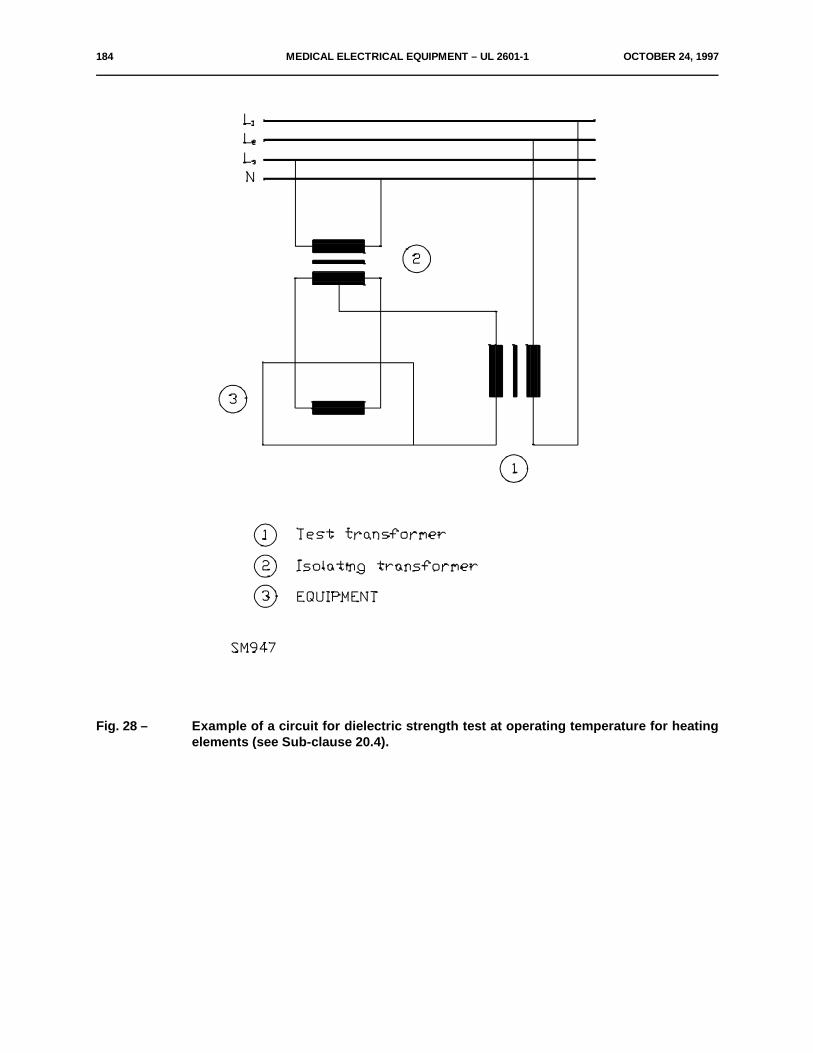
184 MEDICAL ELECTRICAL EQUIPMENT – UL 2601-1 OCTOBER 24, 1997
Fig. 28 – Example of a circuit for dielectric strength test at operating temperature for heatingelements (see Sub-clause 20.4).
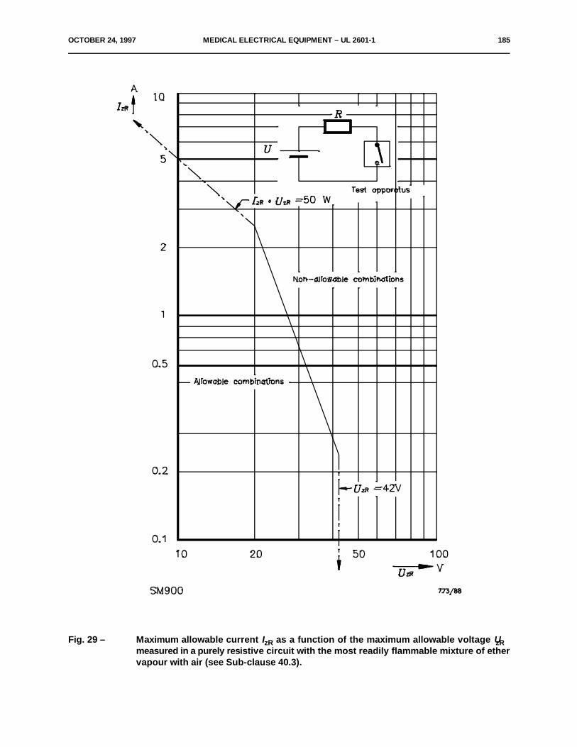
OCTOBER 24, 1997 MEDICAL ELECTRICAL EQUIPMENT – UL 2601-1 185
Fig. 29 – Maximum allowable current I as a function of the maximum allowable voltage UzR zRmeasured in a purely resistive circuit with the most readily flammable mixture of ethervapour with air (see Sub-clause 40.3).
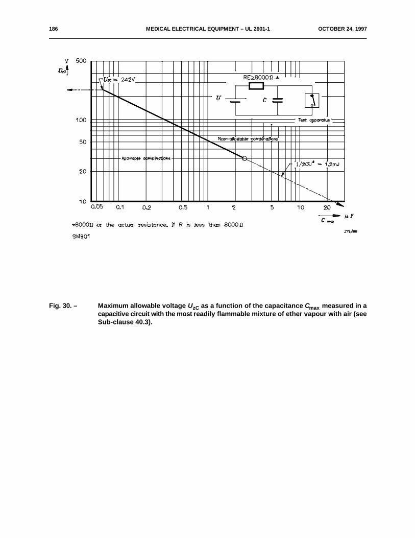
186 MEDICAL ELECTRICAL EQUIPMENT – UL 2601-1 OCTOBER 24, 1997
Fig. 30. – Maximum allowable voltage U as a function of the capacitance C measured in azC maxcapacitive circuit with the most readily flammable mixture of ether vapour with air (seeSub-clause 40.3).

OCTOBER 24, 1997 MEDICAL ELECTRICAL EQUIPMENT – UL 2601-1 187
Fig. 31. – Maximum allowable current I as a function of the inductance L , measured in anzL maxinductive circuit with the most readily flammable mixture of ether vapour with air (seeSub-clause 40.3).
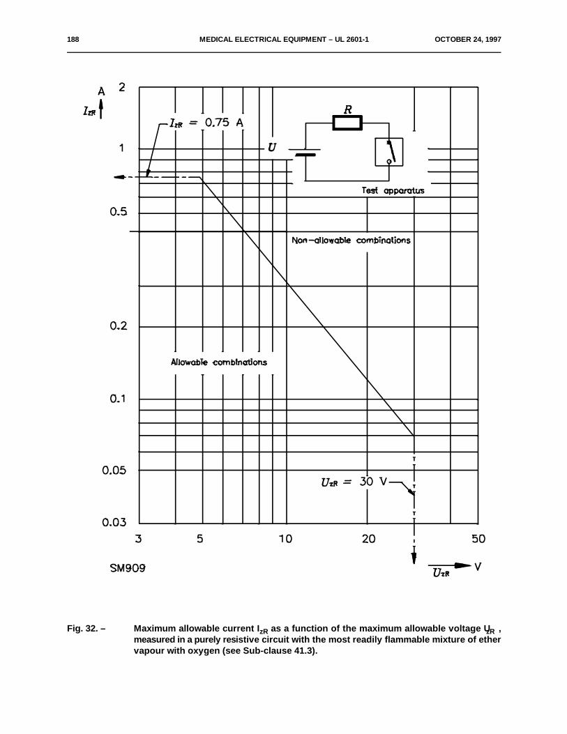
188 MEDICAL ELECTRICAL EQUIPMENT – UL 2601-1 OCTOBER 24, 1997
Fig. 32. – Maximum allowable current I as a function of the maximum allowable voltage U ,zR zRmeasured in a purely resistive circuit with the most readily flammable mixture of ethervapour with oxygen (see Sub-clause 41.3).
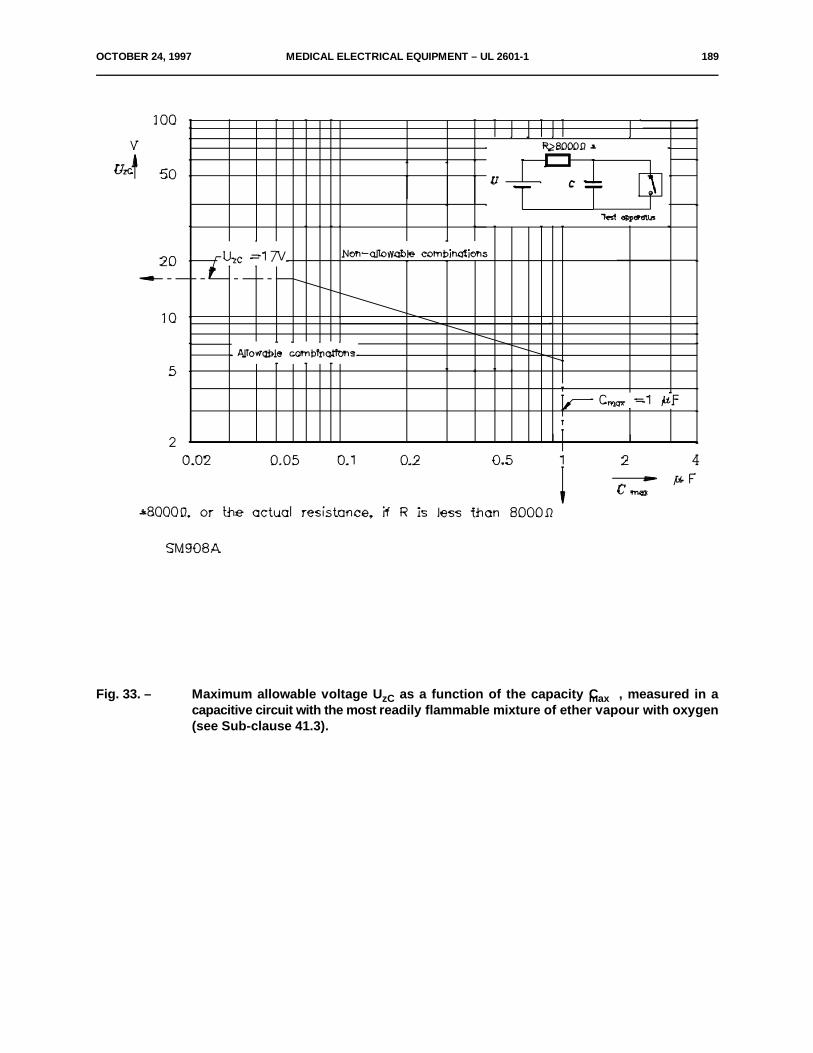
OCTOBER 24, 1997 MEDICAL ELECTRICAL EQUIPMENT – UL 2601-1 189
Fig. 33. – Maximum allowable voltage U as a function of the capacity C , measured in azC maxcapacitive circuit with the most readily flammable mixture of ether vapour with oxygen(see Sub-clause 41.3).
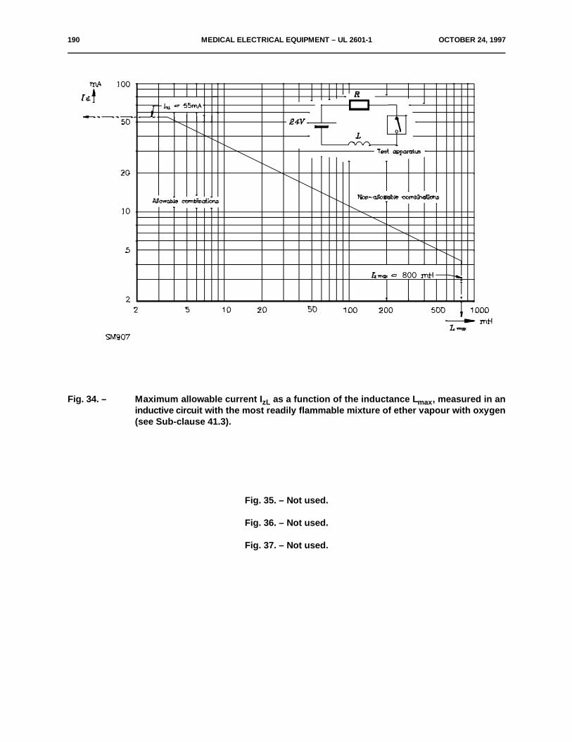
190 MEDICAL ELECTRICAL EQUIPMENT – UL 2601-1 OCTOBER 24, 1997
Fig. 34. – Maximum allowable current I as a function of the inductance L , measured in anzL maxinductive circuit with the most readily flammable mixture of ether vapour with oxygen(see Sub-clause 41.3).
Fig. 35. – Not used.
Fig. 36. – Not used.
Fig. 37. – Not used.
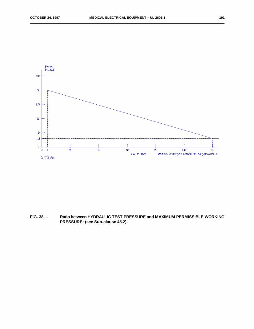
OCTOBER 24, 1997 MEDICAL ELECTRICAL EQUIPMENT – UL 2601-1 191
FIG. 38. – Ratio between HYDRAULIC TEST PRESSURE and MAXIMUM PERMISSIBLE WORKINGPRESSURE: (see Sub-clause 45.2).

192 MEDICAL ELECTRICAL EQUIPMENT – UL 2601-1 OCTOBER 24, 1997
Condition: Path under consideration includes a parallel-or converging-sided groove of any depth witha width less than 1 mm.
Rule: CREEPAGE DISTANCE and AIR CLEARANCE aremeasured directly across the groove as shown.
Fig. 39. – Example 1 (see Sub-clause 57.10).
Condition: Path under consideration includes a parallel-sided groove of any depth and equal to ormore than 1 mm.
Rule: AIR CLEARANCE is the "line of sight" distance.Creepage path follows the contour of thegroove.
Fig. 40 – Example 2 (see Sub-clause 57.10).
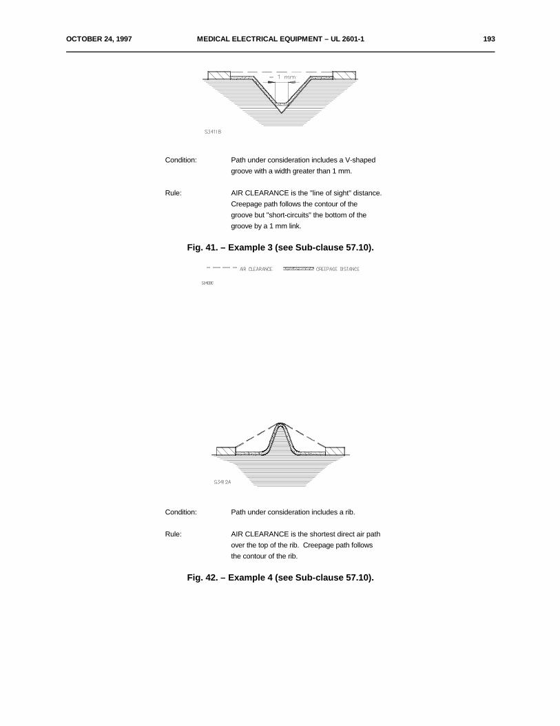
OCTOBER 24, 1997 MEDICAL ELECTRICAL EQUIPMENT – UL 2601-1 193
Condition: Path under consideration includes a V-shapedgroove with a width greater than 1 mm.
Rule: AIR CLEARANCE is the "line of sight" distance.Creepage path follows the contour of thegroove but "short-circuits" the bottom of thegroove by a 1 mm link.
Fig. 41. – Example 3 (see Sub-clause 57.10).
Condition: Path under consideration includes a rib.
Rule: AIR CLEARANCE is the shortest direct air pathover the top of the rib. Creepage path followsthe contour of the rib.
Fig. 42. – Example 4 (see Sub-clause 57.10).
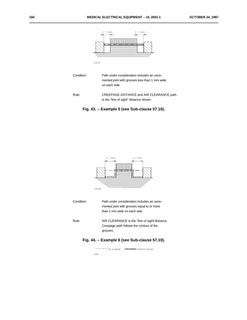
194 MEDICAL ELECTRICAL EQUIPMENT – UL 2601-1 OCTOBER 24, 1997
Condition: Path under consideration includes an unce-mented joint with grooves less than 1 mm wideon each side.
Rule: CREEPAGE DISTANCE and AIR CLEARANCE pathis the "line of sight" distance shown.
Fig. 43. – Example 5 (see Sub-clause 57.10).
Condition: Path under consideration includes an unce-mented joint with grooves equal to or morethan 1 mm wide on each side.
Rule: AIR CLEARANCE is the "line of sight"distance.Creepage path follows the contour of thegrooves.
Fig. 44. – Example 6 (see Sub-clause 57.10).
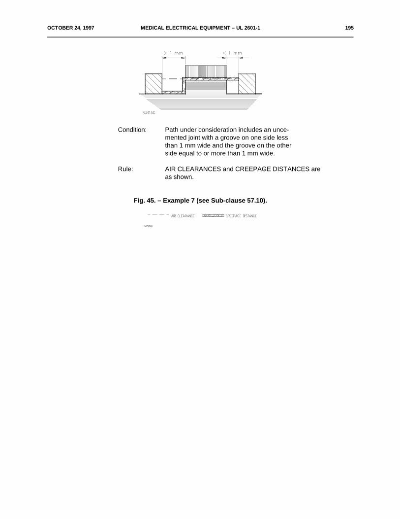
OCTOBER 24, 1997 MEDICAL ELECTRICAL EQUIPMENT – UL 2601-1 195
Condition: Path under consideration includes an unce-mented joint with a groove on one side lessthan 1 mm wide and the groove on the otherside equal to or more than 1 mm wide.
Rule: AIR CLEARANCES and CREEPAGE DISTANCES areas shown.
Fig. 45. – Example 7 (see Sub-clause 57.10).
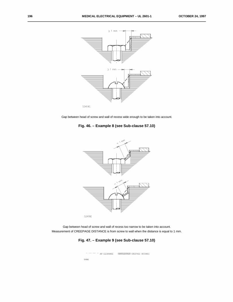
196 MEDICAL ELECTRICAL EQUIPMENT – UL 2601-1 OCTOBER 24, 1997
Gap between head of screw and wall of recess wide enough to be taken into account.
Fig. 46. – Example 8 (see Sub-clause 57.10)
Gap between head of screw and wall of recess too narrow to be taken into account.Measurement of CREEPAGE DISTANCE is from screw to wall when the distance is equal to 1 mm.
Fig. 47. – Example 9 (see Sub-clause 57.10)
OCTOBER 24, 1997 MEDICAL ELECTRICAL EQUIPMENT – UL 2601-1 197
Legends to Figures 39 to 47(see Sub-clause 57.10)
1) The following methods for determination of CREEPAGE 2) LIVE parts which are varnished, enamelled or oxidized only areDISTANCES and AIR CLEARANCES shall be used in interpreting considered to be bare LIVE parts. Coverings of any insulatingthe requirements of this Standard. The methods do not material, however, may be considered as insulation, if the coveringdifferentiate between gaps and grooves nor between types of is equivalent to a foil of insulating material of equal thickness withinsulation. respect to its electrical, thermal and mechanical properties.
The following assumptions are made:
a) A transverse groove may have parallel, converging or 3) If CREEPAGE DISTANCES or AIR CLEARANCES arediverging sides. interrupted by a floating conductive part, the sum of the sections
shall not be less than the minimum specified value given in TableXVI. Distances less than 1 mm are not taken into consideration.If the reference voltage is above 1000 V, attention should be paidto the voltage division by the capacitances.
b) Any corner with included angle less than 80E may beassumed to be bridged with an insulating link of 1 mm movedinto the least favourable position (see Figure 41).
c) Where the distance across the top of a groove is 1 mm or 4) If there are grooves transverse to the CREEPAGE DISTANCE,more, no CREEPAGE DISTANCE exists across the air the wall of the groove is counted as CREEPAGE DISTANCE onlyspace (see Figure 40). if the width of the groove is more than 1 mm (see Figure 40). In all
other cases the groove is neglected.
d) CREEPAGE DISTANCES and AIR CLEARANCES 5) In the case of barriers placed on the surface of insulation ormeasured between parts moving relative to each other are held in a recess, the CREEPAGE DISTANCE may be measuredconsidered in their least favourable position. over the barrier only if the latter is so fixed that dust and moisture
cannot penetrate into the joint or recess.e) Computed CREEPAGE DISTANCE is never less thanmeasured AIR CLEARANCE.
f) Any air gap less than 1 mm wide is ignored in computing 6) Narrow gaps, running into the direction of a possible creepagethe total AIR CLEARANCE (see Figures 39 to 47). path and being some tenths of 1 mm wide only, should be avoided
as far as possible, for dirt and moisture may deposit there.
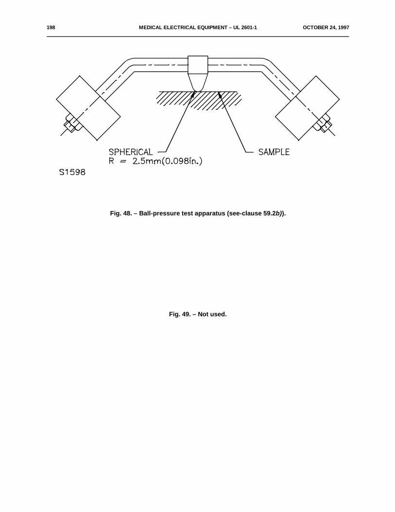
198 MEDICAL ELECTRICAL EQUIPMENT – UL 2601-1 OCTOBER 24, 1997
Fig. 48. – Ball-pressure test apparatus (see-clause 59.2b)).
Fig. 49. – Not used.
OCTOBER 24, 1997 MEDICAL ELECTRICAL EQUIPMENT – UL 2601-1 199
No Text On This Page
200 MEDICAL ELECTRICAL EQUIPMENT – UL 2601-1 OCTOBER 24, 1997
APPENDIX A
GENERAL GUIDANCE AND RATIONALE*
A1. General GuidanceThis general safety Standard for MEDICAL ELECTRICAL EQUIPMENT is necessary because
of the particular relationship of such EQUIPMENT to the PATIENT, the OPERATOR and thesurroundings. The following aspects play an important role in this relationship:a) The inability of PATIENT or OPERATOR to detect the presence of certain potential hazards,
such as ionizing or high-frequency radiation.b) Absence of normal reactions of the PATIENT who may be ill, unconscious, anaesthetized,
immobilized, etc.c) Absence of normal protection to currents provided by the PATIENT's skin, if this is penetrated
or treated to obtain a low skin-resistance.d) Support or replacement of vital body functions may depend on the reliability of EQUIPMENT.e) The simultaneous connection to the PATIENT of more than one piece of EQUIPMENT.f) Combination of high-power EQUIPMENT and sensitive low-signal EQUIPMENT often in ad
hoc combinations.g) The application of electrical circuits directly to the human body, either through contacts to the
skin and/or through the insertion of probes into internal organs.h) Environmental conditions, particularly in operating theaters, may present a combination of
humidity, moisture and/or fire or explosion hazards caused by air, oxygen or nitrous oxidecombined with anaesthetic media and cleaning agents.
A1.1 Safety of MEDICAL ELECTRICAL EQUIPMENT, as described in IEC Publication 513, is partof the total safety situation, comprising safety of EQUIPMENT, safety of the installation in medicallyused rooms of medical establishments and safety of application.
Safety of EQUIPMENT is required for NORMAL USE and NORMAL CONDITION and forSINGLE FAULT CONDITIONS. Reliability of functioning is regarded as a safety aspect for life-supporting EQUIPMENT and where interruption of an examination or treatment is considered as aSAFETY HAZARD for the PATIENT.
Adequate construction and lay-out which serve to prevent human errors are regarded as safetyaspects.
Safety precautions are considered acceptable if they provide adequate protection without anundesirable restriction of normal function.
Generally it is presumed that EQUIPMENT is operated under the jurisdiction of qualified orlicensed persons, that the OPERATOR has the skill required for a particular medical application andthat he acts according to the instructions for use.
The total safety of EQUIPMENT may consist of:– Protective precautions incorporated in the EQUIPMENT (unconditional safety).– Additional protective precautions, such as the use of shields or protective clothing
(conditional safety).
OCTOBER 24, 1997 MEDICAL ELECTRICAL EQUIPMENT – UL 2601-1 201
– Restriction in the instructions for use concerning transport, mounting and/orpositioning, connection, putting in service, operation and the position of theOPERATOR and his assistants in relation to the EQUIPMENT during use (descriptivesafety).
Generally, safety precautions are presumed to be applied in the order as describedhere. They may be attained by sound engineering (which includes knowledge of methods ofproduction and environmental conditions during manufacture, transport, storage and use), byapplication of redundancy and/or by protective devices of a mechanical or electrical nature.
Reference to other publications is only made if such publications are of a generalnature, that is, not restricted to particular equipment types (see References, page 235). Inother cases requirements and tests have been adopted unmodified or slightly modified,without quoting the source.
A1.2 Guidance to the second editionIn this second edition a number of clauses and sub-clauses from the first edition have
been deleted as, e.g., when no test requirements are available or when it is indicated "underconsideration".
In order to indicate the relevant subject the title is kept, so that Particular Standardsmay refer to this sub-clause.
The paragraphs concerning the content of Particular Standards have been movedfrom Clause l to this Appendix (A2 Sub-clause 1.3).
Specifications of environmental conditions formerly in Sub-clause 1.4 now appear asa requirement for EQUIPMENT in Clause 10, where it is stated that compliance with theserequirements for operation is considered to have been checked by application of the test ofthis Standard.
The new specification of the scope (Sub-clause 1.1) refers to a new definition ofMEDICAL ELECTRICAL EQUIPMENT which is considered to be more appropriate and morepractical (see Sub-clause 2.2.15).
A new defined concept PROTECTIVELY EARTHED has been introduced.The term SAFETY HAZARD and its definition will simplify referencing in the standard
itself (see Sub-clause 2.12.18).The standard now distinguishes between an OPERATOR of EQUIPMENT and a
USER, who may be considered responsible for its proper application and maintenance (seeSub-clauses 2.12.17 and 2.12.13).
The sequence of Sub-clauses of Clause 14 was rationalized. Paragraphs which hadbeen derived from IEC Publication 536 (1976) and which were of descriptive nature have beendeleted.
The requirements for the separation between an APPLIED PART and LIVE parts werealso applied to the separation between ACCESSIBLE PARTS and LIVE parts (see Clause 17).The PATIENT currents allowed where CREEPAGE DISTANCE and AIR CLEARANCES areless than the values in Sub-clause 57.10 were changed from the values for SINGLE FAULTCONDITION to those for NORMAL CONDITION.
The requirement in Sub-clause 18e for a facility for connection of a POTENTIALEQUALIZATION CONDUCTOR was withdrawn and replaced with requirements for theconstruction of such a connection if provided.
All references to an additional PROTECTIVE EARTH CONDUCTOR were deleted,because the protective function of such a conductor was no longer recognized.

202 MEDICAL ELECTRICAL EQUIPMENT – UL 2601-1 OCTOBER 24, 1997
The sequence of sub-clauses of Clause 18 was rationalized.An appendix was added illustrating the connection of the APPLIED PART for
measurement of the PATIENT LEAKAGE CURRENT and of the PATIENT AUXILIARYCURRENT (see Appendix K and Sub-clause 19.1e).
The allowable ENCLOSURE LEAKAGE CURRENT for TYPE CF EQUIPMENT inNORMAL CONDITION was changed from 0.01 mA to 0.1 mA.
EQUIPMENT with a high EARTH LEAKAGE CURRENT due to compliance withrequirements for radio-interference suppression was recognized.
Sub-clauses 19.4a and 20.4a were changed.A true r.m.s. meter was recognized as a suitable instrument for LEAKAGE CURRENT
measurements.Clause 20 was rearranged in a number of ways:
– The requirements for the insulation between the MAINS PART and other parts wereextended to include all LIVE parts, but restricted to cases where a SAFETY HAZARDwould develop.
– For each particular insulation a statement was added to clarify that such insulationwould be BASIC, SUPPLEMENTARY, DOUBLE or REINFORCED INSULATION.
– As a result all references to the Class of EQUIPMENT (I, II, INTERNALLYPOWERED) could be deleted and Tables V, VI and VII replaced by one new muchsimplified Table V. Test voltages for reference voltages of more than 10000 V werereferred to Particular Standards.
– The insulation between an F-TYPE APPLIED PART and the BODY of theEQUIPMENT was reviewed to distinguish the case where such an APPLIED PARTwould contain voltages which would make the PATIENT LIVE when the insulationwould become defective (see new categories B-d and B-e).
– Sub-clauses 20.1, 20.2, 20.3 and 20.4 were rearranged to include exclusively allstatements pertaining to their titles.
– The new version of Clause 20 has led to an important simplification of Sub-clause57.10 in Section Ten (AIR CLEARANCES and CREEPAGE DISTANCES).
A1.3 Protection against electric shock hazardsProtection against electric shocks caused by currents not resulting from the specified
physical phenomena of EQUIPMENT may be obtained by a combination of the followingmeasures:– prevention of contact between the body of the PATIENT, the OPERATOR, or a third
person and parts which are LIVE or may become LIVE in the case of an insulationfailure, by means of enclosing, guarding or mounting in inaccessible locations;
– restriction of voltages on or currents from parts which may be touched intentionallyor unintentionally by the PATIENT, the OPERATOR or a third person. These voltagesor currents may be present during NORMAL USE or may appear in SINGLE FAULTCONDITION.
Generally, this protection is obtained by a combination of:– limitation of voltage and/or energy, or protective earthing (see Clauses 15 and 18);– enclosing and/or guarding of LIVE parts (see Clause 16);– insulation of adequate quality and construction (see Clause 17).
OCTOBER 24, 1997 MEDICAL ELECTRICAL EQUIPMENT – UL 2601-1 203
The value of electric current flowing in the human or animal body which may causea certain degree of stimulation varies from individual to individual, according to the way inwhich the connection to the body is made and according to the frequency of the currentapplied and its duration.
Currents of low frequency flowing directly into or through the heart considerablyincrease the danger of ventricular fibrillation. For currents of medium or high frequency, therisk of electric shock is less or negligible, but the risk of burning remains.
The sensitivity of the human or animal body to electric currents, depending upon thedegree and nature of contact with the EQUIPMENT, leads to a classification of EQUIPMENTaccording to the degree and quality of protection. This is described in terms of the maximumallowable LEAKAGE CURRENT (TYPES B, BF and CF EQUIPMENT). TYPES B and BFEQUIPMENT are suitable for applications involving external or internal contact with thePATIENT, excluding the heart. TYPE CF EQUIPMENT is suitable for DIRECT CARDIACAPPLICATION.
In conjunction with this classification, the requirements for allowable LEAKAGECURRENT have been formulated. The absence of sufficient scientific data concerning thesensitivity of the human heart for currents causing ventricular fibrillation still presents aproblem.
Nevertheless, engineers are provided with data enabling them to design EQUIPMENT;so, for the time being, the requirements represent what is considered reasonably safe.
The requirements for LEAKAGE CURRENT were formulated taking into account:a) that the possibility of ventricular fibrillation is influenced by factors other than only
electrical parameters;b) that the values for allowable LEAKAGE CURRENTS in SINGLE FAULT CONDITION
should be as high as is considered safe, taking into account statistical considerations,and
c) that values for NORMAL CONDITION are necessary to create a safe condition in allsituations by providing a sufficiently high safety factor with respect to SINGLE FAULTCONDITIONS.
The measurement of LEAKAGE CURRENTS has been described in a way whichenables the use of simple instruments, avoiding different interpretations of a given case andindicating possibilities for periodic checking by the USER (to be described in the ApplicationCode).
The dielectric strength requirements are included to check the quality of the insulationmaterial used at different places in the EQUIPMENT.
A1.4 Protection against mechanical hazardsRequirements in Section Four are divided into one part describing SAFETY HAZARDS caused
by damage or deterioration of EQUIPMENT (mechanical strength) and several parts describinghazards of a mechanical nature caused by EQUIPMENT (injury by moving parts, by rough surfaces,by sharp edges and corners, by instability, by expelled parts, by vibration and noise and by breakdownof PATIENT supports and of suspension means for EQUIPMENT parts).
EQUIPMENT may become unsafe because of parts damaged or deteriorated by mechanicalstresses such as blows, pressures, shocks, vibration, by ingress of solid particles, dust, fluids andmoisture and aggressive gases, by thermal and dynamic stresses, by corrosion, by loosening offastenings of a moving part or a suspended mass and by radiation.
204 MEDICAL ELECTRICAL EQUIPMENT – UL 2601-1 OCTOBER 24, 1997
Effects of mechanical overloads, material failure or wear can be avoided by:
– means which interrupt or render non-hazardous the operation or the energy-supply (forexample, fuses, pressure valves) as soon as overloading occurs;
– means which guard against or catch flying or falling parts (caused by material failures, wearor overload) which may constitute a SAFETY HAZARD.
Protection against breakdown of PATIENT supports and suspensions can be provided byredundancy or the provision of safety catches.
EQUIPMENT parts which are intended to be held in the hand or positioned on a bed must besufficiently robust to withstand a fall. They may be subject to vibration and shocks, not only whentransported but also when used in vehicles.
A1.5 Protection against hazards from unwanted or excessive radiation
A1.5.1 Radiation from MEDICAL ELECTRICAL EQUIPMENT may occur in all forms known in physics.Safety requirements are concerned with unwanted radiation. Protective measures are necessary forEQUIPMENT and for the environment and methods for determining levels of radiation must bestandardized.
Limits for EQUIPMENT may have to be exceeded for the intended application, where themedical supervisor takes the responsibility. For ionizing radiation IEC requirements generally complywith ICRP Recommendations. Their purpose is to provide data which are immediately usable bydesigner and USER.
Their evaluation is possible only by adequate study of operating methods and duration ofoperation of EQUIPMENT and positioning of USER and assistants, because application of worst caseconditions would give rise to situations which might hamper proper diagnosis or treatment.
Recent ICRP publications also instruct the USER in methods for the restriction of intentionalirradiation.
A1.5.2 High frequency radiation above 0.15 MHz is normally directly harmful only if produced atsubstantial energy levels, for example, by diathermy and surgical EQUIPMENT. However, thisradiation may, even when produced at fairly low energy levels, influence the function of sensitiveelectronic devices and cause interference in radio and television reception.
Constructional requirements can hardly be given, but limits and measuring methods have beendescribed in CISPR publications.
The sensitivity of EQUIPMENT to external interference (electromagnetic field, perturbationsof the supply voltage) is under consideration.
A1.6 Protection against hazards of ignition of flammable anaesthetic mixtures
A1.6.1 ApplicabilityWhere EQUIPMENT is used in areas in which flammable anesthetics and/or flammable
agents for disinfection and/or skin cleaning are applied, an explosion risk may exist if such anestheticsor agents are mixed with air, or with oxygen or nitrous oxide.
OCTOBER 24, 1997 MEDICAL ELECTRICAL EQUIPMENT – UL 2601-1 205
Ignition of such a mixture may be caused by sparks or by contact with parts having a highsurface temperature.
Sparks may be caused where electrical circuits are opened or closed by operation of switches,connectors, fuses or OVER-CURRENT RELEASES and the like.
In high voltage parts sparks may be caused by corona. Static discharges may cause sparks.The probability of ignition of such anaesthetic mixtures depends on their concentration, the
appropriate minimum ignition energy, the presence of high surface temperatures and the energy ofsparking.
The hazard caused by an ignition depends on the location and on the relative quantity of themixture.
A1.6.2 Industrial equipment and components
The constructional requirements of IEC Publication 79 are generally not appropriate forMEDICAL ELECTRICAL EQUIPMENT for several reasons:a) they lead to constructions of a size, weight or design which are not applicable for medical
reasons and/or which may not be sterilizable;b) some constructions allow an explosion inside an enclosure, but prevent propagation outside
it. Such a construction which may be inherently safe would be unacceptable in an operatingtheater where continuity of operation of EQUIPMENT is essential;
c) industrial requirements were made for flammable agents mixed with air. They cannot beapplied to mixtures with oxygen or nitrous oxide used in medical practice;
d) in medical practice flammable anaesthetic mixtures occur only in relatively small quantities.However some of the constructions described in IEC Publication 79 are acceptable for
CATEGORY AP EQUIPMENT (see Sub-clause 40.1).
A1.6.3 Requirements for MEDICAL ELECTRICAL EQUIPMENT
The location of flammable anaesthetic mixtures is described:
– as much as necessary for the construction of EQUIPMENT in Clause 37 of this Standard, asminimum for specified conditions of exhaust and absorption;
– as much as necessary for the allocation of EQUIPMENT and the construction of the electricalinstallation in IEC Publication 364.
That standard additionally provides information on flammable concentrations of a number offlammable agents, their usual application concentrations, ignition temperatures, lowest ignition energyand flash-points. Requirements for ventilation and exhaust of areas, maintenance of a minimumrelative humidity and permission to use certain equipment types in certain areas may be subject to local(hospital) or national and possibly legal regulations.
The requirements, limits and tests of this section are based on the results of statisticalconsiderations obtained from experiments with the most readily flammable mixtures of ether vapor withair and with oxygen, using the test apparatus described in Appendix F. This is justified becausecombinations with ether have the lowest ignition temperatures and the lowest ignition energies ofcommonly used agents.

206 MEDICAL ELECTRICAL EQUIPMENT – UL 2601-1 OCTOBER 24, 1997
Where temperatures or circuit parameters of EQUIPMENT used in a FLAMMABLEANAESTHETIC MIXTURE WITH AIR exceed allowable limits and sparking cannot be avoided therelevant parts and circuits can be enclosed in ENCLOSURES with pressurized inert gas or clean airor in ENCLOSURES with restricted breathing.
ENCLOSURES with restricted breathing delay the build-up of an ignitable concentration. Theyare recognized because it is assumed that a period in which EQUIPMENT is used in a FLAMMABLEANAESTHETIC MIXTURE WITH AIR is followed by a period of ventilation during which such aconcentration will disappear.
For EQUIPMENT containing or used in a FLAMMABLE ANAESTHETIC MIXTURE WITHOXYGEN OR NITROUS OXIDE, requirements, limits and tests are far more stringent.
Requirements apply not only to NORMAL CONDITION but, additionally, in the SINGLE FAULTCONDITION, as indicated in Sub-clause 3.6. Only two exemptions from an actual ignition test arerecognized, these being either the absence of sparks and limited temperature or limited temperatureand restricted circuit parameters.
A1.7 Protection against excessive temperatures and other safety hazards
– Temperatures (see Clause 42)Temperature limits are required to prevent hazards for almost all types of electricalEQUIPMENT with the purpose of preventing rapid ageing of insulation and discomfort whereEQUIPMENT is touched or manipulated, or injuries where PATIENTS may contactEQUIPMENT parts.EQUIPMENT parts may be inserted into body cavities, usually temporarily but sometimespermanently.For PATIENT contact, special temperature limits have been set.
– Preventing fire hazard (Clause 43)Except for CATEGORY AP and CATEGORY APG EQUIPMENT the fire hazard of MEDICALELECTRICAL EQUIPMENT may be subject to requirements in Particular Standards.The normal limits for operating temperatures and requirements for overload protection areapplicable.
– Pressure vessels (Clause 45)Attention is drawn to the requirements dealing with pressure vessels and parts subject topressure, where no local regulations are available.
– Interruption of the power supply (Clause 49)Interruption of the power supply may cause a SAFETY HAZARD.
A1.8 Accuracy of operating data and protection against incorrect output
IEC Publication 601-1 is the guideline for all Particular Standards and must therefore containsome requirements of a more general character in order to serve this purpose. So it is necessary tohave some generally formulated requirements in Section Eight.
OCTOBER 24, 1997 MEDICAL ELECTRICAL EQUIPMENT – UL 2601-1 207
It is also, for the time being, and for several reasons, impossible to provide standards, evenurgently needed, for a number of kinds of MEDICAL ELECTRICAL EQUIPMENT.
Standardization bodies, including those outside IEC, have taken over the system of this IECPublication in order to have an unique system of standards. In such cases it is most important to givea guideline in this section as a help towards "functional" PATIENT safety.
A1.9 Abnormal operation and fault conditions causing electric shock, overheating and/or mechanicaldamage; environmental tests
EQUIPMENT or parts of EQUIPMENT may cause, due to abnormal operation, excessivetemperatures or other SAFETY HAZARDS. Therefore these abnormal operations or fault conditionsmust be investigated.
A2. Rationale to particular clauses and sub-clauses
Clause 1Particular Standards can in further sub-clauses specify the particular subject and it should be
quite clear as to what is being referred to in the General Standard and in the Particular Standard.Only such laboratory equipment is included in the scope of this Standard which is related to
the PATIENT in such a way that the PATIENT's safety can be influenced.Laboratory equipment within the scope of IEC SC 66E is not covered by this Standard.
Combinations of EQUIPMENT developed by the USER may not conform to this Standard evenif they are composed of EQUIPMENT that, taken separately, satisfy the requirements of this Standard.
Sub-clause 1.3
A Particular Standard may state:– clauses of the General Standard which apply without amendment;– clauses or sub-clauses (or parts of them) of the General Standard which do not apply;– clauses or sub-clauses (or parts of them) of the General Standard which are replaced by a
clause or a sub-clause in a Particular Standard;– any additional clauses or sub-clauses.
A Particular Standard may contain:a) requirements which result in an increased degree of safety;b) requirements which may be less stringent than the requirements in this General Standard, if
the latter cannot be maintained because of, for example, the power output of EQUIPMENT;c) requirements concerning performance, reliability, interfaces, etc.;d) accuracy of working data;e) extension of environmental conditions.
Sub-clause 2.2.24
TYPE B EQUIPMENT is, for example, suitable for intentional external and internal applicationto the PATIENT, excluding DIRECT CARDIAC APPLICATION.
208 MEDICAL ELECTRICAL EQUIPMENT – UL 2601-1 OCTOBER 24, 1997
Sub-clause 2.2.26TYPE CF EQUIPMENT is primarily intended for DIRECT CARDIAC APPLICATION.
Sub-clause 2.3.2This definition does not necessarily include insulation used exclusively for functional purposes.
Sub-clause 2.3.4BASIC INSULATION and SUPPLEMENTARY INSULATION can, if required, be tested
separately.
Sub-clause 2.3.7The term "insulation system" does not imply that the insulation must be one homogeneous
piece. It may comprise several layers which cannot be tested separately as SUPPLEMENTARY orBASIC INSULATION.
Sub-clause 2.4.3This definition is based on IEC Publications 364-4-41 and 536.
Sub-clause 2.5.4This is distinct from what was formerly referred to as "patient functional current" which is
intended to produce a physiological effect, for example, current necessary for nerve and musclestimulation, cardiac pacing, defibrillation, high-frequency surgical procedures.
Sub-clause 2.7.6Cord sets are covered by IEC Publication 320.
Sub-clause 2.11.2The MAXIMUM PERMISSIBLE WORKING PRESSURE is decided by a competent person,
taking into account the original design specification, the manufacturer's rating, the current condition ofthe vessel and the circumstances of use.
In some countries, the figure may be reduced from time to time.
Sub-clause 2.12.2The MODEL OR TYPE REFERENCE is intended to establish its relationship to commercial
and technical publications, to ACCOMPANYING DOCUMENTS and between separable parts ofEQUIPMENT.
Sub-clause 3.6As stated in Sub-clause 3.1 EQUIPMENT is required to remain safe in SINGLE FAULT
CONDITION. Thus one fault of a single protective means is allowed.The probability of simultaneous occurrence of two single faults is considered small enough
to be negligible.This condition can only be relied upon if either:
a) the probability of a single fault is small, because of sufficient design reserve, or the presenceof a double protection prevents the development of a first single fault, or
b) a single fault causes operation of a safety device (e.g. a fuse, OVER-CURRENT RELEASE,safety catch, etc.) which prevents occurrence of a SAFETY HAZARD, or
c) a single fault is discovered by an unmistakable and clearly discernible signal which becomesobvious to the OPERATOR, or
OCTOBER 24, 1997 MEDICAL ELECTRICAL EQUIPMENT – UL 2601-1 209
d) a single fault is discovered and remedied by periodic inspection and maintenance which isprescribed in the instructions for use.
Non-exclusive examples of the categories a) to d) are:a) REINFORCED or DOUBLE INSULATION;b) CLASS I EQUIPMENT in case of a fault in BASIC INSULATION;c) Abnormal indications of displays, defect in a redundant suspension cord causing excessive
noise or friction;d) Deterioration of a flexible protective earth connection which is moved in NORMAL USE.
Sub-clause 3.6c)The appearance of an external voltage on an F-TYPE APPLIED PART (which may be
conductively connected to a SIGNAL INPUT PART or to a SIGNAL OUTPUT PART) would have to becaused by a double failure of protective means in other EQUIPMENT, simultaneously connected tothe PATIENT and complying with this Standard, or by a single failure of protective means in equipmentnot complying with this Standard. As such this condition is very unlikely in good medical practice.
However, since the main safety feature of EQUIPMENT with an F-TYPE APPLIED PART isthat the PATIENT is not earthed by the connection to the EQUIPMENT, the electrical separation of anF-TYPE APPLIED PART from earth must have a minimum quality. This is assured by the requirementthat, even if a hypothetical voltage of supply frequency and equal to the highest supply voltage to earthpresent in the PATIENT'S environment would appear on the APPLIED PART, the limit for the PATIENTLEAKAGE CURRENT would not be exceeded.
In this hypothetical case the PATIENT is supposed not to be connected to the APPLIED PART.
Clause 4In EQUIPMENT there may be many pieces of insulation, components (electrical and
mechanical) and constructional features in which a failure would not produce a SAFETY HAZARD toPATIENT, OPERATOR or surroundings, even though causing a deterioration in or a failure ofperformance of EQUIPMENT.
Sub-clause 4.1In order to ensure that every individually produced item of EQUIPMENT conforms to this
Standard, the manufacturer and/or installer should carry out such measures during manufactureand/or installation assembly as to ensure that each item satisfies all requirements even if it is notcompletely tested individually during manufacture or installation.
Such measures may take the form of:a) production methods (to ensure good manufacturing output and constant quality) where such
quality would be related to safety;b) production tests (routine tests) performed on every produced item;c) production tests performed on a production sample where results would justify a sufficient
confidence level.Production tests may not be identical with type tests, but may be adapted to manufacturing
conditions and possibly invoking less risk for the quality of the insulation or other characteristicsimportant for safety.
Production tests would, of course, be restricted to setting (possibly derived from type tests)which would provoke the worst case situation.

210 MEDICAL ELECTRICAL EQUIPMENT – UL 2601-1 OCTOBER 24, 1997
Depending upon the nature of EQUIPMENT, production methods and/or tests may concerncritical insulation of the MAINS PART, of the APPLIED PART and the insulation and/or the separationbetween these parts.
Suggested test parameters could be leakage current and dielectric strength.Where applicable, the continuity of protective earthing may be a major test parameter.
Sub-clause 4.3Whether a sample is representative is decided by the test laboratory and the manufacturer.
Sub-clause 4.8The aim is to verify that EQUIPMENT is operating properly.
Sub-clause 4.10a) The humidity preconditioning treatment and subsequent tests of MEDICAL ELECTRICAL
EQUIPMENT are often performed in laboratories suitable for treatment and tests forhousehold and similar electrical appliances.To avoid unnecessary investments and costs for such laboratories, preconditioning treatmentsand tests should be aligned as far as is feasible.
b) According to Sub-clause 2.2.28, the ENCLOSURE of WATER-TIGHT EQUIPMENT prevents,under stated conditions, the entry of an amount of water where its presence could cause' aSAFETY HAZARD.The test condition as well as the acceptable amount and location of water are to be definedin Particular Standards. If no ingress of water is tolerated (sealed ENCLOSURES) theapplication of the humidity preconditioning treatment is inappropriate.
c) To prevent condensation when EQUIPMENT is placed in the humidity cabinet, thetemperature of such a cabinet must be equal to or slightly lower than the temperature of theEQUIPMENT when it is introduced. To avoid the need for a temperature stabilization systemfor the air in the room outside the cabinet, the cabinet air temperature during the treatment isadapted to that of the outside air within the limits of the range of + 20EC to + 32EC and then"stabilized" at the initial value. Although the effect of the cabinet temperature on the degreeof absorption of humidity is recognized, it is felt that the reproductibility of test results is notimpaired substantially and the cost-reducing effect is considerable.
d) DRIP-PROOF EQUIPMENT and SPLASH-PROOF EQUIPMENT may be used in anenvironment where the humidity is higher than the humidity of the environment in whichordinary EQUIPMENT is used.Therefore such EQUIPMENT is kept in the humidity cabinet for 7 days (see Sub-clause 4.10,7th paragraph).
Clause 5EQUIPMENT may have a multiple classification.
Sub-clause 5.1The safety of Class III equipment is critically dependent on the installation and on other Class
III equipment connected thereto. These factors are outside the control of the OPERATOR and this isconsidered to be unacceptable for MEDICAL ELECTRICAL EQUIPMENT. Additionally, limitation ofvoltage is not sufficient to ensure safety of the PATIENT. For these reasons this Standard does notrecognize Class III equipment in this second edition.
OCTOBER 24, 1997 MEDICAL ELECTRICAL EQUIPMENT – UL 2601-1 211
Sub-clause 6.1f).Although a MODEL OR TYPE REFERENCE usually denotes a certain performance
specification, it may possible not denote the exact construction, including the applied components andmaterials. If this is required, the MODEL OR TYPE REFERENCE may have to be supplemented bya SERIAL NUMBER. The SERIAL NUMBER may also be used for other purposes.
Indication of a manufacturing series only may not be sufficient if local requirements requireindividual identification.
Sub-clause 6.1)The rubbing test is performed with distilled water, methylated spirit and isopropyl alcohol.Isopropyl alcohol is defined in the European Pharmacopoeia as a reagent in the following
terms:C H O (MW60.1) - Propanol. Isopropyl alcohol. A clear colorless liquid with a characteristic2 8
odor, mixable with water and with alcohol. It has a relative density of about 0.785, boiling-point 81ECto 83EC.
Sub-clause 6.7For colors of indicator lights see also IEC Publication 73.
Sub-clause 6.8.1The subject of languages used in markings and in ACCOMPANYING DOCUMENTS cannot
be solved by IEC. Even a requirement that identifications and ACCOMPANYING DOCUMENTS haveto be in the national languages cannot be upheld worldwide.
Sub-clause 6.8.2b)Responsibility of the manufacturerThe instructions for use may contain a statement saying that the manufacturer, assembler,
installer or importer considers himself responsible for the effects on safety, reliability and performanceof the EQUIPMENT only if:– assembly operations, extensions, readjustments, modifications or repairs are carried out by
persons authorized by him,– the electrical installation of the relevant room complies with the appropriate requirements, and– the EQUIPMENT is used in accordance with the instructions for use.
Sub-clause 10.2.1These environmental conditions are based on the conditions in buildings without air-
conditioning in climates where the ambient temperature occasionally reaches +40EC.
The EQUIPMENT covered by this Standard may not be suitable for use in pressure chambers.
Sub-clause 10.2.2Because of the wide range of MEDICAL ELECTRICAL EQUIPMENT covered in this Standard,
it is not possible to specify the permissible effects on performance of each particular type ofEQUIPMENT due to MAINS VOLTAGE and frequency fluctuations.
In this Standard such effects are covered in a number of safety tests.According to Fortescue's theorem any unbalanced polyphase system can be resolved in three
balanced systems of phases:
212 MEDICAL ELECTRICAL EQUIPMENT – UL 2601-1 OCTOBER 24, 1997
a) a system of so-called positive sequence components of equal magnitude and phase angle,but having the opposite phase sequence as the original system;
b) a system of so-called negative sequence components of equal magnitude and phase angle,but having the same phase sequence as the original system;
c) a system of so-called zero sequence components of equal magnitude, no mutual phase angle(in phase) and no phase sequence (stationary vectors). Systems without a neutral conductorcannot have zero sequence current components.
The zero sequence current can be determined as the sum of the three phase currents dividedby three.
Thus the neutral current is three times the zero sequence current.
Literature: – Elements of Power Systems AnalysisW.D. Stevenson, Jr.McGraw Hill (page 272)– IEEE Vol. 37 Part II (1918) page 1329Modern Power SystemsNeuenswonderpage 183, Measurement of Zero Sequence.
Sub-clause 14.1b)EQUIPMENT, specified for an external d.c. power source (e.g. for use in an ambulance), has
to satisfy all requirements for CLASS I or CLASS II EQUIPMENT.
Sub-clause 14.4The combination of isolated supply and the restricted voltage is regarded as an additional
protective measure against electric shock hazard.
Clause 16ENCLOSURES and PROTECTIVE COVERS are intended to provide protection for human
beings against contact with parts that are LIVE or may become LIVE after a single failure of protectiveinsulation. They may, at the same time, provide protection against other hazards (mechanical,thermal, chemical, etc.).
"Accidental contact" means that parts are touched in NORMAL USE by a human being, withoutthe aid of a TOOL and without appreciable force.
Except in special cases, such as PATIENT supports and waterbeds, contact with EQUIPMENTis supposed to be made with:– one hand, simulated by a metal foil of 10 cm x 20 cm (or less if the total EQUIPMENT is
smaller);– one finger, straight or bent in a natural position, simulated by a test finger provided with a stop
plate;– a pencil or pen, held in a hand, simulated by a guided test pin;– a necklace or similar pendant, simulated by a metal rod suspended over openings in a top
cover;– a screwdriver for adjustment of a preset control by the USER, simulated by an inserted metal
rod;– an edge or slit that can be pulled outward allowing subsequent entry of a finger, simulated by
a combination of test hook and test finger.
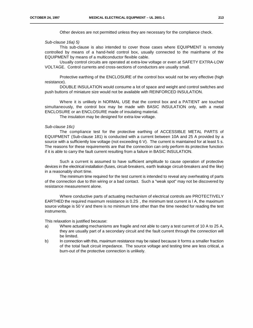
OCTOBER 24, 1997 MEDICAL ELECTRICAL EQUIPMENT – UL 2601-1 213
Other devices are not permitted unless they are necessary for the compliance check.
Sub-clause 16a) 5)This sub-clause is also intended to cover those cases where EQUIPMENT is remotely
controlled by means of a hand-held control box, usually connected to the mainframe of theEQUIPMENT by means of a multiconductor flexible cable.
Usually control circuits are operated at extra-low voltage or even at SAFETY EXTRA-LOWVOLTAGE. Control currents and cross-sections of conductors are usually small.
Protective earthing of the ENCLOSURE of the control box would not be very effective (highresistance).
DOUBLE INSULATION would consume a lot of space and weight and control switches andpush buttons of miniature size would not be available with REINFORCED INSULATION.
Where it is unlikely in NORMAL USE that the control box and a PATIENT are touchedsimultaneously, the control box may be made with BASIC INSULATION only, with a metalENCLOSURE or an ENCLOSURE made of insulating material.
The insulation may be designed for extra-low voltage.
Sub-clause 16c)The compliance test for the protective earthing of ACCESSIBLE METAL PARTS of
EQUIPMENT (Sub-clause 181) is conducted with a current between 10A and 25 A provided by asource with a sufficiently low voltage (not exceeding 6 V). The current is maintained for at least 5 s.The reasons for these requirements are that the connection can only perform its protective functionif it is able to carry the fault current resulting from a failure in BASIC INSULATION.
Such a current is assumed to have sufficient amplitude to cause operation of protectivedevices in the electrical installation (fuses, circuit-breakers, earth leakage circuit-breakers and the like)in a reasonably short time.
The minimum time required for the test current is intended to reveal any overheating of partsof the connection due to thin wiring or a bad contact. Such a "weak spot" may not be discovered byresistance measurement alone.
Where conductive parts of actuating mechanism of electrical controls are PROTECTIVELYEARTHED the required maximum resistance is 0.2S , the minimum test current is l A, the maximumsource voltage is 50 V and there is no minimum time other than the time needed for reading the testinstruments.
This relaxation is justified because:a) Where actuating mechanisms are fragile and not able to carry a test current of 10 A to 25 A,
they are usually part of a secondary circuit and the fault current through the connection willbe limited.
b) In connection with this, maximum resistance may be raised because it forms a smaller fractionof the total fault circuit impedance. The source voltage and testing time are less critical, aburn-out of the protective connection is unlikely.
214 MEDICAL ELECTRICAL EQUIPMENT – UL 2601-1 OCTOBER 24, 1997
Sub-clause 16d)The use of the Symbol 14, Table DI, "Attention, consult ACCOMPANYING DOCUMENTS" of
Appendix D is not sufficient. A warning notice on the outside of the EQUIPMENT may be sufficient.
Clause 17Air may form part or all of the BASIC INSULATION and/or SUPPLEMENTARY INSULATION.
Sub-clause 18a)
Generally, ACCESSIBLE CONDUCTIVE PARTS of CLASS I EQUIPMENT shall be connectedpermanently and with sufficiently low impedance to the PROTECTIVE EARTH TERMINAL.
However, CLASS I EQUIPMENT may contain ACCESSIBLE PARTS which are so separatedfrom the MAINS PART that, in NORMAL CONDITION and SINGLE FAULT CONDITION of theinsulation of the MAINS PART or of the protective earthing, the LEAKAGE CURRENT from theseACCESSIBLE PARTS to earth does not exceed the value of Table IV (see Clause 19).
In this case, these ACCESSIBLE PARTS need not be connected to a PROTECTIVE EARTHTERMINAL but they may be connected to, for example, a FUNCTIONAL EARTH TERMINAL, or theymay be left floating.
The separation of ACCESSIBLE METAL PARTS from the MAINS PART may be obtained byDOUBLE INSULATION, by metallic screening or by a PROTECTIVELY EARTHED ACCESSIBLEMETAL PART or a PROTECTIVELY EARTHED secondary circuit, separating the ACCESSIBLEMETAL PARTS completely from the MAINS PART.
Metal parts behind a decorative cover, which does not comply with the mechanical strengthtest, are regarded as ACCESSIBLE METAL PARTS.

OCTOBER 24, 1997 MEDICAL ELECTRICAL EQUIPMENT – UL 2601-1 215
The fault current may be limited to a relatively low value, because of inherent impedance orthe characteristic of the power source, for example where the power system is not connected to earthor connected to it via a high impedance.
In such cases the cross-section of the protective earthing connection may be determinedprimarily by mechanical considerations.
Sub-clause 19.1d)The ENCLOSURE LEAKAGE CURRENT of CLASS I EQUIPMENT from PROTECTIVELY
EARTHED parts is negligible in NORMAL CONDITION.
Sub-clause 19.2a)The breakdown of BASIC INSULATION in CLASS I EQUIPMENT is not generally regarded
as a SINGLE FAULT CONDITION as the LEAKAGE CURRENTS in this case cannot be kept withinallowable limits (Table IV) during the time before a fuse, or OVER-CURRENT RELEASE operates.Exceptionally, LEAKAGE CURRENTS are measured during short-circuiting BASIC INSULATION incases where there are doubts concerning the effectiveness of protective earth connections inside theEQUIPMENT (see Sub-clauses 17a and 17g).
Sub-clause 19.3 and Table IV
Allowable values of continuous LEAKAGE and PATIENT AUXILIARY CURRENTS for a.c. andd.c. composite waveforms with frequencies up to and including 1 kHz.
– In general the risk of ventricular fibrillation or pump failure increases with the value or duration,up to a few seconds, of the current passing through the heart. Some areas of the heart aremore sensitive than others. That is, a current that causes ventricular fibrillation when appliedto one part of the heart may have no effect when applied to another part of the heart.
– The risk is highest and approximately equal for frequencies in the 10 to 200 Hz range. It islower, by a factor of nearly 5, at d.c. and by approximately 1.5 at 1 kHz. Beyond 1 kHz, therisk decreases rapidly. 1) The values in Table IV cover the range from d.c. to 1 kHz. SUPPLYMAINS frequencies of 50 and 60 Hz are in the range of highest risk.
– Although as a general rule requirements in a General Standard are less restrictive than therequirements in Particular Standards, some of the allowable values in Table IV have been setat such a value that:a) the majority of EQUIPMENT types can comply, andb) they can be applied to most EQUIPMENT types (existing or future) for which no
Particular Standards exist.
EARTH LEAKAGE CURRENT– The allowable values for EARTH LEAKAGE CURRENT are not critical and have been chosen
to avoid any significant increase in the currents flowing through the protective earthing systemof the installation.
– In Note 2) to Table IV is stated under which conditions higher EARTH LEAKAGE CURRENTSare allowed if internal conductive parts are not accessible.
1) See references page 220.
216 MEDICAL ELECTRICAL EQUIPMENT – UL 2601-1 OCTOBER 24, 1997
– In Note 3) to Table IV is stated that EQUIPMENT with a fixed and permanently installedPROTECTIVE EARTH CONDUCTOR may have higher allowable EARTH LEAKAGECURRENTS as the accidental interruption of the PROTECTIVE EARTH CONDUCTOR is veryunlikely.
ENCLOSURE LEAKAGE CURRENTThe limits are based on the following considerations:
a) The ENCLOSURE LEAKAGE CURRENT of TYPE CF EQUIPMENT in NORMAL CONDITIONwas raised to the same level as for TYPES B, BF EQUIPMENT because such EQUIPMENTmay be used simultaneously on a PATIENT.
b) The ENCLOSURE LEAKAGE CURRENT may flow through the PATIENT to earth. In the caseof TYPE B EQUIPMENT via the APPLIED PART and in the case of TYPE BF and CFEQUIPMENT by indirect contact with the ENCLOSURE via the OPERATOR.
The current density created at the heart by current entering the chest is 50 µA/mm per2
ampere. ) The current density at the heart for 500 µA (maximum allowable value in SINGLE8
FAULT CONDITION) entering the chest is 0.025 µA/mm , well below the level of concern.2
c) The probability of the ENCLOSURE LEAKAGE CURRENT flowing through the heart andcausing ventricular fibrillation or pump failure.
ENCLOSURE LEAKAGE CURRENT could conceivably reach an intracardiac site if carelessprocedures are used in handling intracardiac conductors or fluid filled catheters. Such devicesshould always be handled with great care and always with dry rubber gloves.
The probability of a direct contact between an intracardiac device and an EQUIPMENTENCLOSURE is considered to be very low, perhaps 1 in 100 procedures. The probability ofan indirect contact via the medical staff is considered to be somewhat higher, say 1 in 10procedures. The maximum allowable LEAKAGE CURRENT in NORMAL CONDITION is 100µA which itself has a probability of inducing ventricular fibrillation of 0.05. If the probability ofindirect contact is 0.1 then the overall probability is 0.005. Although this probability wouldappear undesirably high, it should be recalled that with correct handling of the intracardiacdevice this probability can be reduced to that for mechanical stimulation alone, 0.001.The probability of the ENCLOSURE LEAKAGE CURRENT rising to the maximum allowablelevel of 500 µA (SINGLE FAULT CONDITION) is considered to be 0.1 in departments withpoor maintenance procedures. The probability of this current causing ventricular fibrillationis taken as 1. The probability of accidental contact directly with the ENCLOSURE is, as above,considered as 0.01, giving an overall probability of 0.001, equal to the mechanical stimulationalone probability.The probability of ENCLOSURE LEAKAGE CURRENT at the maximum allowable level of 500µA (SINGLE FAULT CONDITION) being conducted to an intracardiac device via the medicalstaff is 0.01 (0.1 for the SINGLE FAULT CONDITION, 0.1 for accidental contact). Since theprobability of this current causing ventricular fibrillation is 1, the overall probability is also 0.01.Again this probability is high; however it can be brought down to the mechanical stimulationalone probability of 0.001 by adequate procedures.
8) See references page 220.

OCTOBER 24, 1997 MEDICAL ELECTRICAL EQUIPMENT – UL 2601-1 217
d) The probability of the ENCLOSURE LEAKAGE CURRENT being perceptible to the PATIENT.
The probability of 500 µA being perceptible is 0.01 for men and 0.014 for women when usinggrip electrodes with intact skin. ) There is a higher perceptibility for current passing through1,2
mucous membranes or skin punctures. ) Since distribution is normal ), there will be a2 1
probability that some PATIENTS will perceive very small currents. One person is reported tohave sensed 4 µA passing through a mucous membrane. )2
ENCLOSURE LEAKAGE CURRENT for TYPE B, BF and CF EQUIPMENT is made equalbecause all types of EQUIPMENT may be used simultaneously on a PATIENT.
PATIENT LEAKAGE CURRENT
The allowable value of PATIENT LEAKAGE CURRENT for TYPE CF EQUIPMENT inNORMAL CONDITION is 10 µA which has a probability of 0.002 for causing ventricular fibrillation orpump failure when applied through small areas to an intracardiac site.
Even with zero current, it has been observed that mechanical irritation can produce ventricularfibrillation. ) A limit of 10 µA is readily achievable and does not significantly increase the risk of4
ventricular fibrillation during intracardiac procedures.
The 50 µA maximum allowed in SINGLE FAULT CONDITION for TYPE CF EQUIPMENT isbased on a value of current which has been found, under clinical conditions, to have a very lowprobability of causing ventricular fibrillation or interference with the pumping action of the heart.
For catheters 1.25-2 mm diameter likely to contact the myocardium, the probability of 50 µAcausing ventricular fibrillation is near 0.01 (see Figure A1 and its explanation). Small cross-sectionarea (0.22 mm and 0.93 mm ) catheters used in angiography have higher probabilities of causing2 2
ventricular fibrillation or pump failure if placed directly on sensitive areas of the heart.
The overall probability of ventricular fibrillation being caused by PATIENT LEAKAGECURRENT in SINGLE FAULT CONDITION is 0.001 (0.1 for probability of SINGLE FAULTCONDITION, 0.01 probability of 50 µA causing ventricular fibrillation) equal to the probability formechanical stimulation alone.
The 50 µA current allowed in SINGLE FAULT CONDITION is not likely to result in a currentdensity sufficient to stimulate neuromuscular tissues nor, if d.c., cause necrosis.
For TYPE B and TYPE BF EQUIPMENT where the maximum allowable PATIENT LEAKAGECURRENT under SINGLE FAULT CONDITION is 500 µA, the same rationale applies as that forENCLOSURE LEAKAGE CURRENT since this current will not flow directly to the heart.
See references page 220.1,2,4)
218 MEDICAL ELECTRICAL EQUIPMENT – UL 2601-1 OCTOBER 24, 1997
The probability of MAINS VOLTAGE appearing on the PATIENT is considered to be extremelylow. For this to happen the following faults must have occurred:
a) failure of PROTECTIVE EARTHING of CLASS I EQUIPMENT (probability of 0.l);
b) a fault in BASIC INSULATION. The probability, based on experience, is less than 0.01.
This gives an overall probability of 0.001 of MAINS VOLTAGE appearing on the PATIENT.
For TYPE CF EQUIPMENT the PATIENT LEAKAGE CURRENT will be limited to 50 µA, noworse than the previously discussed SINGLE FAULT CONDITION.
For TYPE BF EQUIPMENT the maximum PATIENT LEAKAGE CURRENT under theseconditions is 5 mA. Even this value entering the chest would produce only a current density at the heartof 0.25 µA/mm . This current would be very perceptible to the PATIENT, however the probability of2
its occurrence is very low.
PATIENT AUXILIARY CURRENT
The allowable values for PATIENT AUXILIARY CURRENT are for EQUIPMENT such asimpedance plethysmographs, these apply to currents having a frequency not less than 0.l Hz. Lowervalues are given for d.c. to prevent tissue necrosis with long-term application.
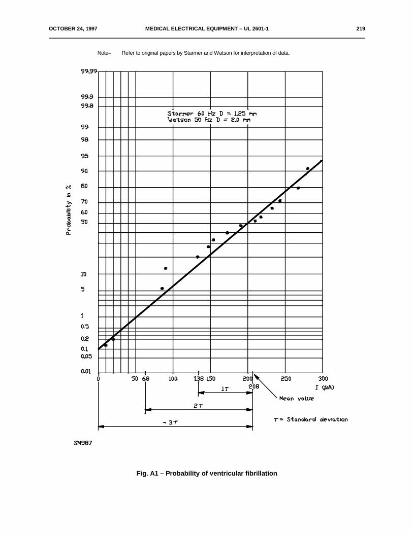
OCTOBER 24, 1997 MEDICAL ELECTRICAL EQUIPMENT – UL 2601-1 219
Note– Refer to original papers by Starmer and Watson for interpretation of data.
Fig. A1 – Probability of ventricular fibrillation
220 MEDICAL ELECTRICAL EQUIPMENT – UL 2601-1 OCTOBER 24, 1997
Explanation of Figure A1Articles by Starmer ) and Watson ) provide data on ventricular fibrillation caused by 50 Hz and6 7
60 Hz currents applied directly to the hearts of human populations with cardiac disease. Fibrillationprobability was obtained as a function of the electrode diameter and the magnitude of the current. Forelectrodes of 1.25 mm and 2 mm diameter and currents up to 0.3 mA, the distribution appears normal.Accordingly, it has been extrapolated to encompass the values commonly used in assessing PATIENTrisk (values noted on Figure A1). From this extrapolation, it is seen that:
a) any value of current, however small, has some probability of causing ventricular fibrillation,and
b) the commonly used values have low probabilities, ranging from approximately 0.002 to 0.01.
Since ventricular fibrillation is governed by many factors (PATIENT condition, probability ofcurrent entering a more sensitive area of the myocardium, probability of fibrillation as a function ofcurrent or current density, physiology, electric field, etc.), it is reasonable to use statistics in determiningthe possibility of risk for the multiple conditions.
References
1) Charles F. Dalziel; Re-evaluation of lethal electric currents, IEEE Transactions on Industry andGeneral Applications, Vol. l GA-4, No. 5, September/October 1968.
2) Kohn C. Keesey, Frank S. Letcher; Human thresholds of electric shock at power transmissionfrequencies; Arch. Environ. Health, Vol. 21, October 1970.
3) O. Z. Roy; 60 Hz Ventricular fibrillation and rhythm thresholds and the non-pacing intracardiaccatheter; Medical and Biological Engineering, March 1975.
4) E. B. Rafferty, H. L. Green, M. H. Yacoub; Cardiovascular Research; Vol. 9, No. 2, pp. 263-265, March 1975.
5) H. L. Green; Electrical Safety Symposium Report; Department of Health and Social Security;United Kingdom, October 1975.
6) C. Frank Starmer, Robert E. Whalen; Current density and electrically induced ventricularfibrillation; Medical Instrumentation; Vol. 7, No. 1, January-February 1973.
7) A. B. Watson, J. S. Wright; Electrical thresholds for ventricular fibrillation in man; MedicalJournal of Australia; June 16, 1973.
8) A. M. Dolan, B. M. Horacek, P. M. Rautaharaju; Medical Instrumentation (abstract), January12, 1953, 1978.
Sub-clause 19.4a)Although it is recognized that absorption of humidity by insulation would have a far greater
effect on the resistance of the insulation than on the capacitance of it, the results of a resistance,measurement would be influenced heavily by the choice of the moment when the measurement wasmade. Such results could thus become irreproducible.
To improve reproducibility even further it was proposed to retain the LEAKAGE CURRENT testand to start it l h after the end of the humidity preconditioning treatment. It was considered that if adeterioration of insulation resistance would become a safety risk, it would also be noticeable in anincreased LEAKAGE CURRENT and in the results of the dielectric strength test.
OCTOBER 24, 1997 MEDICAL ELECTRICAL EQUIPMENT – UL 2601-1 221
Sub-clause 19.4b)The switches S or S + S or S + S + S , in Figures 10, 11, 12 and 13 may be omitted and1 1 2 1 2 2
the interruptions of the relevant leads may be obtained by other means.Instead of the single or polyphase isolating transformers with adjustable output voltage(s), as
shown in Figures 10, 11, 12, 13 and 14, a combination of an isolating transformer with fixed outputvoltage and an auto-transformer with adjustable output voltage may be used.
Sub-clause 19.4 Table IVThe current flowing from the APPLIED PART, due to an external voltage on the APPLIED
PART to earth in BF TYPE EQUIPMENT of 5 mA is allowed because the risk of harmful physiologicaleffects is small and the appearance of 220 V on the PATIENT is very unlikely.
Sub-clause 19.4d)Although it is not unlikely that EQUIPMENT is used while placed on or in an earthed metal
environment, such a position would be rather difficult to describe in a way that test results wouldbecome reproducible. The first statement is therefore to be considered as a convention.
The likelihood that PATIENT cables have an important capacitance to earth is usuallyimportant and of considerable influence on test results. A position providing reproducible results istherefore prescribed.
Sub-clause 19.4e) 4)The measuring device represents a measuring method which takes into account the
physiological effect of a current through the human body, including the heart.
Sub-clause 19.4h)Care should be taken that the capacitance of the measuring device and its connecting leads
to earth and to the body of the equipment is kept as low as possible.Instead of an isolating transformer T with an adjustable output voltage, a combination of an2
isolating transformer with a fixed output voltage and an auto-transformer with an adjustable outputvoltage may be used.
Sub-clause 20.3Components in EQUIPMENT which are subjected to a dielectric strength test according to
Clause 20, like fuseholder, push-buttons, switches etc. will be subjected to the relevant test voltages.If these components cannot fulfil these requirements, due to the specification of the relevantcomponent, additional measures may be taken in the EQUIPMENT (e.g. by additional insulationmaterial) (see also Sub-clauses 4.4 and 56.1).
Sub-clause 20.4a)Since the dielectric strength test as described in Sub-clause 20.4a is applied immediately after
the humidity preconditioning treatment, with the EQUIPMENT still in the humidity cabinet, adequateprecautions for the protection of laboratory personnel may be necessary.
Sub-clause 20.4b)The test voltage may be provided by a transformer, a d.c. power source or by using the
transformer(s) of the EQUIPMENT. In the last case, to prevent overheating due to increasedinductance, the test voltage may have a frequency which is higher than the RATED frequency of theEQUIPMENT.
222 MEDICAL ELECTRICAL EQUIPMENT – UL 2601-1 OCTOBER 24, 1997
The procedure and duration of the test for reference voltages equal to or higher than 1000 Va.c. or 1 500 V d.c. or peak values may be specified further by Particular Standards.
Sub-clause 20.4g)This may be avoided, for example in the case of a transformer, by the use of a voltage divider
with a tapping point connected to the core or some other suitable connecting point to ensure thecorrect voltage division over the actual insulations, or by the use of two test transformers, correctlyphased.
Sub-clause 20.4j)Components designed to limit the voltage which may be destroyed by power dissipation during
the dielectric strength test may be removed when the test is made.
Sub-clause 21.5The tests for hand-held EQUIPMENT or EQUIPMENT parts is different from the test for
PORTABLE and MOBILE EQUIPMENT because of the difference in practical application.
Sub-clause 21.6Contrary to what is often assumed, MEDICAL ELECTRICAL EQUIPMENT may be used in a
hostile environment. In case of emergency, EQUIPMENT is carried or wheeled on trolleys overdoorsteps and into elevators and subjected to bumps and vibration. Such conditions may in fact typifyNORMAL USE for some EQUIPMENT.
Clause 22The degree of protection required for ENCLOSURES or guards, protecting moving parts
depends upon the general design and intended use of the EQUIPMENT. Factors to be taken intoconsideration in judging the acceptability of exposed moving parts may be the degree of exposure, theshape of the moving parts, the likelihood of accidental contact, the speed of movement and thelikelihood of fingers, arms or clothing being drawn into moving parts (for example where gears mesh,where belts travel on to a pulley or where moving parts close in a pinching or shearing action).
These factors may be considered with respect to both NORMAL USE and also during settingof any adjustments, or the replacement of any ACCESSORY or attachment, possibly including theinstallation instructions, because guards may be provided at installation and may not be part of a singleitem of STATIONARY EQUIPMENT.
Features of guards that may be considered include:
– removability with the use of TOOLS only;– removability for servicing and replacement;– strength and rigidity;– completeness;– creation of additional hazards such as pinch points, and the necessity for additional handling
because of the increased need for servicing such as for cleaning.
See also rationale to Sub-clause 6.8.2b).
Clause 26In factories and workshops, excessive noise may cause fatigue or even damage to hearing.
Limits to prevent hearing damage are described in ISO Standards.
OCTOBER 24, 1997 MEDICAL ELECTRICAL EQUIPMENT – UL 2601-1 223
In medically used rooms, much lower limits are needed for the comfort of PATIENT andmedical personnel. The actual effect of EQUIPMENT noise is strongly influenced by the acousticalproperties of the room, the insulation between rooms and interaction of EQUIPMENT parts.
Sub-clause 28.5Calculation of forces (dynamic loads) caused by acceleration or deceleration of suspended
masses is often difficult because the acceleration or deceleration may be greatly influenced by theflexibility of several parts whose combined effect is difficult to predict. This applies in particular to hand-driven movements with end-stops. For motor-driven movements, the effects of fault conditions in themotor-control circuitry may have to be considered.
Requirements concerning alternating stresses (including dimensions of guiding means andwheels) are under consideration.
Sub-clause 40.3The graphs of Figures 29, 30 and 31 are given to assist in the design of circuits which fulfil the
requirements for allowable limits stated for CATEGORY AP EQUIPMENT without performing theignition test.
Extrapolation for higher voltages is not valid because the ignition condition of gases changesat higher voltages. The limit for inductances is introduced because high inductance values generallyproduce higher voltages.
Sub-clause 40.4The amount of air or inert gas escaping from the EQUIPMENT by leakage is assumed to be
limited so that hygienic conditions in the medically used room are not disturbed appreciably.
For the purposes of Sub-clauses 40.4 and 40.5 the term "enclosure" may represent either theENCLOSURE as defined in Sub-clause 2.1.6 or a distinct compartment or housing.
Sub-clause 40.5a)This requirement is regarded as sufficient to prevent ignition in NORMAL USE during an
operational period of several hours since average conditions in NORMAL USE are less stringent.
Sub-clause 41.2This requirement prevents the introduction of voltages higher than those permitted by Sub-
clause 41.3. Such voltages can exist on earth wiring.
Sub-clause 41.3The graphs of Figures 32, 33 and 34 are given to assist in the design of circuits which fulfil the
requirements for allowable limits stated for CATEGORY APG EQUIPMENT, without performing theignition test.
Sub-clause 41.5. See also ISO 8185.
Sub-clauses 42.1 and 42.2Tables Xa and Xb originate from IEC Publication 335-I. In Table Xa temperature limits are
listed for ACCESSIBLE PARTS, components with T-marking and classified winding insulations. InTable Xb materials and components are listed, the temperature of which may influence the life ofEQUIPMENT.
224 MEDICAL ELECTRICAL EQUIPMENT – UL 2601-1 OCTOBER 24, 1997
Clause 45The requirements of this clause do not represent the most stringent combination of national
regulations or standards.In some countries such regulations or standards apply.
Sub-clause 45.2It is assumed that if the PRESSURE x volume is equal to or smaller than 200 kPa or the
PRESSURE is equal to or smaller than 50 kPa, a hydraulic test is not necessary.
The safety factors implied by Figure 38 are higher than those generally applied in testingvessels. However, whereas hydraulic testing is normally used to verify that a pressure vessel is freefrom production faults or serious deterioration, the adequacy of the design being determined in otherways, the present hydraulic test is intended to verify the adequacy of a design where this cannot beestablished in other ways.
Sub-clause 45.3The way the maximum PRESSURE in use is determined depends on circumstances.
Clause 46In the first edition the content of this clause dealt only with the interchangeability of
connections, and it has now been moved to Sub-clause 56.3.
Clause 48Guidance may be found in ISO standards, in preparation by TC 150.
Sub-clause 49.2Attention is paid to the effect of a power interruption concerning unwanted movements,
removal of compression forces and removal of PATIENTS from a hazardous position.
Sub-clause 52.4.1– The delivery of unintended hazardous quantities of energy or substances to a PATIENT or into
the environment may be described by Particular Standards.– Hazardous quantities of poisonous or ignitable gas depend on the type of gas, concentration,
place of emission etc.At a power dissipation of 15 W or less, no fire hazard exists.
– The occurrence of malfunctions and failure to operate (breakdown), causing a direct SAFETYHAZARD for a PATIENT (for example non-recognizable failures in life-supportingEQUIPMENT, non-recognizable measuring errors and substitution of PATIENT data) may bedescribed in Particular Standards.
Sub-clause 52.5.7The effect of functioning centrifugal switches may be taken into account. A locked rotor
condition is specified because some capacitor motors may or may not start, causing variable results.
Sub-clause 52.5.8, Table XII, last lineTemperature limits of motor windings in EQUIPMENT are determined after the first hour as
an arithmetic average because experience of test houses has shown that EQUIPMENT forINTERMITTENT OPERATION reaches variable values which may temporarily differ from themaximum values.
Therefore a lower temperature limits is required.
OCTOBER 24, 1997 MEDICAL ELECTRICAL EQUIPMENT – UL 2601-1 225
Clause 54In Section Ten, where compliance is specified to be checked by inspection, it may be done by
analysis of the relevant documents presented by the manufacturer.
Sub-clause 54.1Controls, instruments, indicating lamps, etc., which are associated with a specific function of
the EQUIPMENT, should be grouped together (see Section Eight).
Sub-clause 54.2Parts liable to be replaced or adjusted should be so located and secured as to permit
inspection, servicing, replacement and adjustment without damage to, or interference with, adjacentparts or wiring.
Sub-clause 54.3The setting of controls which, if unintentionally changed, may affect safety should be so
designed or guarded that unintentional changing of the setting or adjustments is unlikely.
Mains switches and other vital controls in life-supporting EQUIPMENT and other criticalEQUIPMENT should be so designed or guarded that unintentional switching or changing of the settingis unlikely. Such EQUIPMENT should be identified by Particular Standards.
Controls, instruments, indicators and the like which are associated with a particular functionof the equipment should have their functions clearly marked in accordance with Sub-clause 6.1 andare located so as to minimize the possibility of inadvertent or incorrect adjustment. Where incorrectadjustment of controls can constitute a hazard, appropriate steps should be taken to prevent thispossibility, e.g. by an interlocking device or an additional safety control.
Sub-clause 55.1At least all LIVE parts, with the exception of POWER SUPPLY CORDS and other necessary
interconnecting cords, should be enclosed in material which will not support combustion.
This does not preclude the use of an outer cover of other material covering an inner covercomplying with the above recommendation.
For flammability tests see IEC Publication 695.
Sub-clause 55.2Mechanical strength is described in Section Four.
Sub-clause 56.4Such capacitors cannot provide DOUBLE INSULATION or REINFORCED INSULATION.
Sub-clause 57.2e)This requirement reduces the likelihood of other EQUIPMENT being connected which might
lead to excessive LEAKAGE CURRENT.
EMERGENCY TROLLEYS are exempted to allow rapid exchange of EQUIPMENT inemergencies.

226 MEDICAL ELECTRICAL EQUIPMENT – UL 2601-1 OCTOBER 24, 1997
Sub-clause 57.5a)Terminals of components other than terminal blocks may be used as terminals intended for
external conductors.This practice should be generally discouraged, but allowed in special cases where the terminal
arrangement is adequate (accessible and clearly marked) and complying with this Standard. Thissituation may occur for example in motor starters.
Soldering, clamping and crimping of conductors are equally effective methods.
Sub-clause 5 7.5d)The term "special preparation of the conductor" covers soldering of the strands, use of cord
lugs, attachment of eyelets, etc., but not the reshaping of the conductor before its introduction into theterminal or the twisting of a stranded conductor to consolidate the end.
Sub-clause 57.7Interference suppressors may be connected on the SUPPLY MAINS side of an EQUIPMENT
mains switch or on the SUPPLY MAINS side of any mains fuse or OVER-CURRENT RELEASE.
Sub-clause 57.9The scopes of IEC Publications 742 and 601-I are different. Many types of transformers used
in MEDICAL ELECTRICAL EQUIPMENT are not covered by IEC Publication 742.
For reasons of PATIENT safety additional requirements must be applied to the constructionof such transformers, e.g. restriction of LEAKAGE CURRENTS flowing to PATIENT CIRCUITS.
The contents of Appendix J of the first edition now appear in Sub-clause 57.9.
Future work has to be done in order to establish e.g. appropriate CREEPAGE DISTANCESand AIR CLEARANCES inside transformers, taking into consideration the values for safety isolatingtransformers given in IEC Publication 742.
Requirements for switch-mode power supplies are under consideration.
Sub-clause 57.10Values of CREEPAGE DISTANCES and AIR CLEARANCES are influenced by the following
factors:
a) the reference voltage as defined in Sub-clause 20.3b) The material of the insulation is assumed to have a low resistivity against tracking. A tracking
test according to IEC Publication 112 may indicate lower values for spacings, but the practicalvalue of such a test is being kept under consideration, until a study of the applicability of IECPublication 664 is completed.
c) Spacings for SUPPLEMENTARY INSULATION are equal to those for BASIC INSULATIONeven if the dielectric strength test voltages according to Sub-clause 20.3 are different.Spacings for DOUBLE INSULATION and REINFORCED INSULATION are twice the valuesfor BASIC INSULATION.
OCTOBER 24, 1997 MEDICAL ELECTRICAL EQUIPMENT – UL 2601-1 227
d) For insulation between the ENCLOSURE and an F-TYPE APPLIED PART special rules apply:
1) In the case of an F-TYPE APPLIED PART having no LIVE parts even when theAPPLIED PART is earthed, the insulation between the APPLIED PART and theENCLOSURE will only be stressed to the MAINS VOLTAGE in the case of a singlefault in other EQUIPMENT connected to the PATIENT.
This condition rarely occurs; furthermore this insulation is not normally subject to thetransient overvoltages found in the MAINS PART. In view of the above, the insulationnecessary between the APPLIED PART and the ENCLOSURE for the case quoted,need only satisfy the requirements for BASIC INSULATION.
2) In the case of an F-TYPE APPLIED PART containing parts with voltage difference, theconnection of a part of the APPLIED PART to earth via an earthed PATIENT(NORMAL CONDITION) may result in LIVE parts within the APPLIED PART.
The insulation between such LIVE parts and the ENCLOSURE may be subject, underworst case conditions (when a part of the APPLIED PART is earthed via thePATIENT), to the whole of the voltage within the APPLIED PART.Since this voltage appears in NORMAL CONDITION, even though infrequently, therelevant insulation must satisfy the requirements for DOUBLE INSULATION orREINFORCED INSULATION. In view of the low probability of this condition occurring,the CREEPAGE DISTANCES and AIR CLEARANCES given in Table XVI areconsidered adequate.
3) The value to be applied is the highest of the values found according to Items d)l) andd)2) above.
Sub-clause 59.1e)Conductors may be routed in separated jacketed cords of adequate rating. Where conductors
of different circuit categories have to be run through common cords, wiring channels, conduits orconnecting devices, adequate separation is realized by sufficient rating of the conductor insulation andby arranging for sufficient AIR CLEARANCES and CREEPAGE DISTANCES, complying with therequirements of Sub-clause 57.10, between conductive parts in connecting devices.
Sub-clause 59.2b)Tests concerning flammability of materials will be found in IEC Publication 707.
228 MEDICAL ELECTRICAL EQUIPMENT – UL 2601-1 OCTOBER 24, 1997
APPENDIX B
TESTING DURING MANUFACTURE AND/OR INSTALLATION
Not used. See the rationale to Sub-clause 4.1.

OCTOBER 24, 1997 MEDICAL ELECTRICAL EQUIPMENT – UL 2601-1 229
APPENDIX C
SEQUENCE OF TESTING
C1. GeneralTests should, if applicable, be carried out in the sequence indicated below, unless otherwise
stated by Particular Standards. The sequence of the tests marked by an * is mandatory. See alsoSub-clause 4.11.
However, this does not preclude the possibility of conducting a test which preliminaryinspection suggests might cause failure.
C2. General requirementsSee Sub-clause 3.1 and Clause 4.
C3. MarkingsSee Sub-clauses 6.1 to 6.8.
C4. Power inputSee Clause 7.
C5. ClassificationSee Clause 14.
C6. Limitation of voltage and/or energySee Clause 15.
C7. ENCLOSURES and PROTECTIVE COVERSSee Clause 16.
C8. SeparationSee Clause 17.
C9. Protective earthing, functional earthing and potential equalizationSee Clauses 18 and 58.
C10. Mechanical strengthSee Clause 21.
C11. Moving partsSee Clause 22.
C12. Surfaces, corners and edgesSee Clause 23.
C13. Stability and transportabilitySee Clause 24.
C14. Expelled partsSee Clause 25.
230 MEDICAL ELECTRICAL EQUIPMENT – UL 2601-1 OCTOBER 24, 1997
C15. Suspended massesSee Clause 28.
C16. Radiation hazardsSee Section Five.
C17. Electromagnetic compatibilitySee CISPR recommendations and Sub-clause A1.5.2.
C18. Pressure vessels and parts subject to PRESSURESee Clause 45.
C19. Human errorsSee Clause 46.
C20. Temperatures - Fire preventionSee Clauses 42 and 43.
C21. Interruption of the power supplySee Clause 49.
C22. Accuracy of operating data and protection against incorrect outputSee Clauses 50 and 51.
*C23. Abnormal operation, fault conditions, environmental testsSee Clauses 52 and 53.
*C24. Continuous LEAKAGE CURRENTS and PATIENT AUXILIARY CURRENTS at operating temperatureSee Sub-clause 19.4.
*C25. Dielectric strength at operating temperatureSee Sub-clause 20.4.
*C26. Humidity preconditioning treatmentSee Sub-clause 4.10.
*C27. Dielectric strength test (COLD CONDITION)See Sub-clause 20.4.
*C28. LEAKAGE CURRENT after humidity preconditioning treatmentSee Sub-clause 19.4.
* The sequence of these tests is mandatory.

OCTOBER 24, 1997 MEDICAL ELECTRICAL EQUIPMENT – UL 2601-1 231
*C29. Overflow, spillage, leakage, humidity, ingress of liquids, cleaning, sterilization and disinfectionSee Clause 44, exception Sub-clause 44.7.See Clause C34.
C30. ENCLOSURES and coversSee Clause 55.
C31. Components and general assemblySee Clause 56.
C32. MAINS PARTS, components and layoutSee Clause 57.
C33. Not used, covered by Clause C9.
C34. Construction and layoutSee Clause 59 and Sub-clause 44.7.
C35. CATEGORY AP and CATEGORY APG EQUIPMENTSee Clauses 37 to 41 inclusive.
C36. Verification of markingsSee Sub-clause 6.1, last paragraph.
*The sequence of these tests is mandatory.
232 MEDICAL ELECTRICAL EQUIPMENT – UL 2601-1 OCTOBER 24, 1997
APPENDIX D
SYMBOLS ON MARKING
(See Clause 6)
IntroductionSymbols are frequently used on EQUIPMENT in preference to words with the intention of
obviating language differences and permitting easier comprehension of a marking or indication,sometimes in a restricted space.
If, for the purpose of this Standard, symbols are necessary, the following symbols should beused. See IEC Publications 417 and 878.For symbol requirements not met by these lists refer in the first instance to published IEC or ISOsymbols, noting that, where necessary, two or more symbols may be grouped together to convey aparticular meaning and that, provided the essential communicative characteristics of the basic symbolare maintained, some latitude in graphic design is permissible.
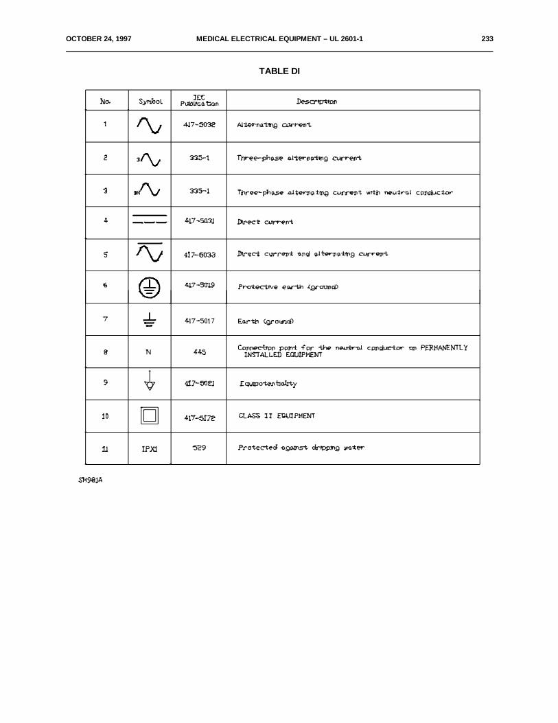
OCTOBER 24, 1997 MEDICAL ELECTRICAL EQUIPMENT – UL 2601-1 233
TABLE DI
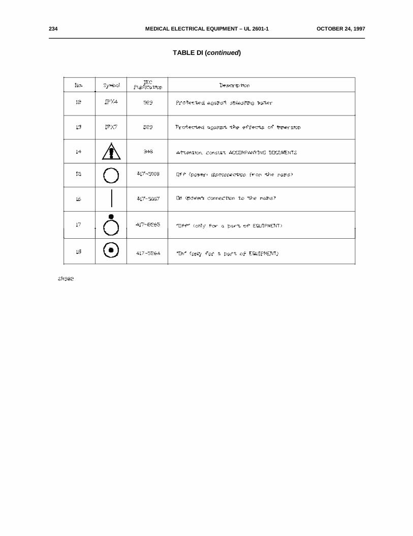
234 MEDICAL ELECTRICAL EQUIPMENT – UL 2601-1 OCTOBER 24, 1997
TABLE DI (continued)
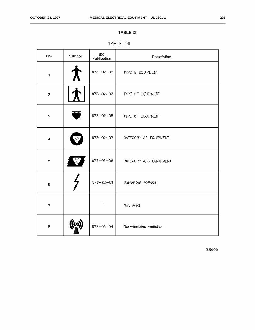
OCTOBER 24, 1997 MEDICAL ELECTRICAL EQUIPMENT – UL 2601-1 235
TABLE DII
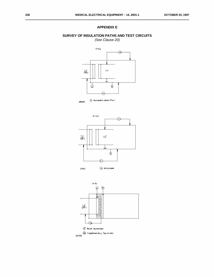
236 MEDICAL ELECTRICAL EQUIPMENT – UL 2601-1 OCTOBER 24, 1997
APPENDIX E
SURVEY OF INSULATION PATHS AND TEST CIRCUITS(See Clause 20)
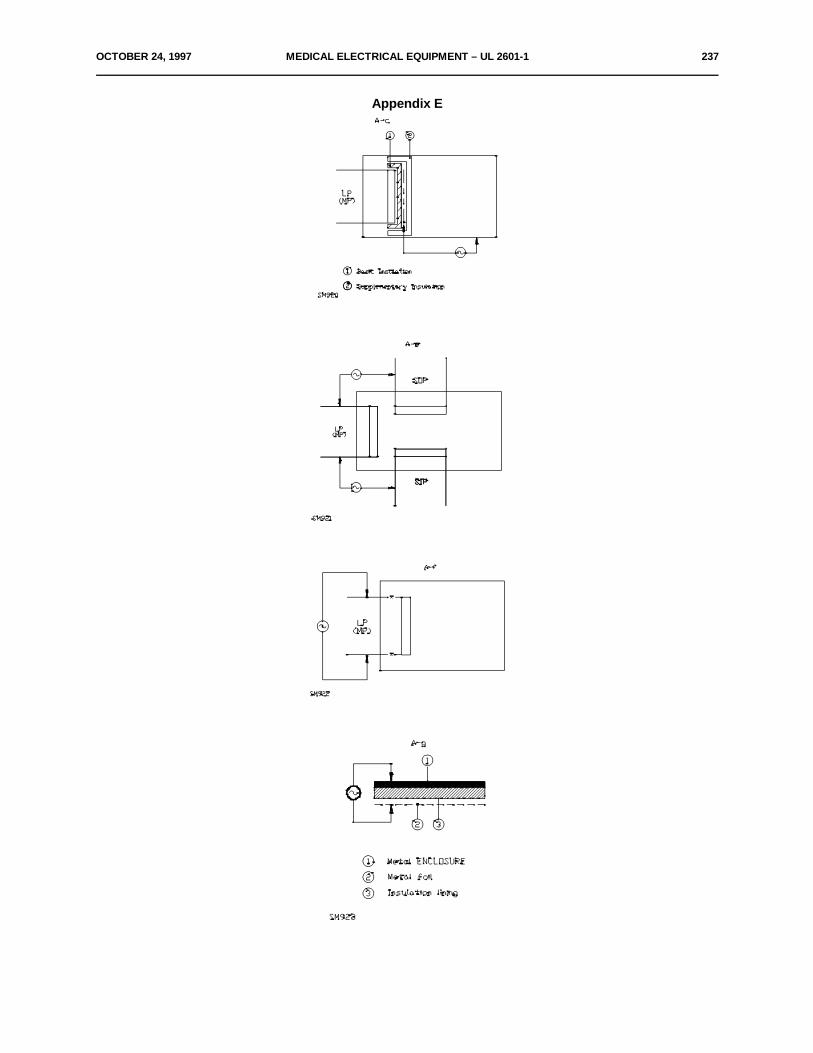
OCTOBER 24, 1997 MEDICAL ELECTRICAL EQUIPMENT – UL 2601-1 237
Appendix E

238 MEDICAL ELECTRICAL EQUIPMENT – UL 2601-1 OCTOBER 24, 1997
Appendix E

OCTOBER 24, 1997 MEDICAL ELECTRICAL EQUIPMENT – UL 2601-1 239
Appendix E
LegendMP – MAINS PARTSOP – SIGNAL OUTPUT PARTSIP – SIGNAL INPUT PARTAP – APPLIED PARTLP – LIVE PARTX – Interruption of circuit for measuring purposes

240 MEDICAL ELECTRICAL EQUIPMENT – UL 2601-1 OCTOBER 24, 1997
APPENDIX F
TEST APPARATUS FOR FLAMMABLE MIXTURES
(See Appendix A, Sub-clause A1.6.3)
The test apparatus comprises an ignition space with a volume of at least 250 cm , which contains the3
prescribed atmosphere or mixture and a contact arrangement (see figure below) providing sparks by openingand closing.
The contact arrangement consists of a cadmium disk with two grooves and a second disk with fourtungsten wires having a diameter of 0.2 mm which slides over the first disk. The free length of the tungstenwires is 11 mm. The shaft to which the tungsten wires are connected rotates with a speed of 80 rev/min. Theshaft connected to the cadmium disk turns in opposite direction to the shaft connected to the disk with wires.
The ratio of the rotation speed of the shaft connected to the wires and the other shaft is 50:12.
Both shafts are isolated from each other and from the frame.
The ignition space must be able to support an internal overpressure of 1.5 MPa.
With the contact arrangement, the circuit to be tested is closed or opened and it is checked if the sparkswill ignite the atmosphere or mixture under test.
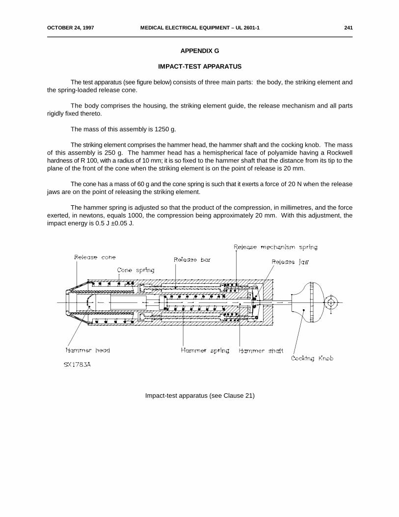
OCTOBER 24, 1997 MEDICAL ELECTRICAL EQUIPMENT – UL 2601-1 241
APPENDIX G
IMPACT-TEST APPARATUS
The test apparatus (see figure below) consists of three main parts: the body, the striking element andthe spring-loaded release cone.
The body comprises the housing, the striking element guide, the release mechanism and all partsrigidly fixed thereto.
The mass of this assembly is 1250 g.
The striking element comprises the hammer head, the hammer shaft and the cocking knob. The massof this assembly is 250 g. The hammer head has a hemispherical face of polyamide having a Rockwellhardness of R 100, with a radius of 10 mm; it is so fixed to the hammer shaft that the distance from its tip to theplane of the front of the cone when the striking element is on the point of release is 20 mm.
The cone has a mass of 60 g and the cone spring is such that it exerts a force of 20 N when the releasejaws are on the point of releasing the striking element.
The hammer spring is adjusted so that the product of the compression, in millimetres, and the forceexerted, in newtons, equals 1000, the compression being approximately 20 mm. With this adjustment, theimpact energy is 0.5 J ±0.05 J.
Impact-test apparatus (see Clause 21)

242 MEDICAL ELECTRICAL EQUIPMENT – UL 2601-1 OCTOBER 24, 1997
APPENDIX H
SCREWED TERMINAL CONNECTIONS
Not used.
APPENDIX J
MAINS SUPPLY TRANSFORMERS
Text transferred to Sub-clause 57.9.
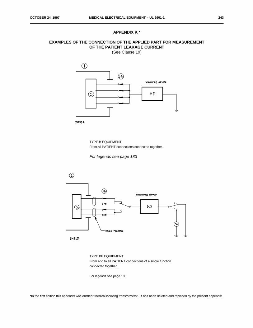
OCTOBER 24, 1997 MEDICAL ELECTRICAL EQUIPMENT – UL 2601-1 243
APPENDIX K *
EXAMPLES OF THE CONNECTION OF THE APPLIED PART FOR MEASUREMENTOF THE PATIENT LEAKAGE CURRENT
(See Clause 19)
TYPE B EQUIPMENTFrom all PATIENT connections connected together.
For legends see page 183
TYPE BF EQUIPMENTFrom and to all PATIENT connections of a single functionconnected together.
For legends see page 183
*In the first edition this appendix was entitled "Medical isolating transformers". It has been deleted and replaced by the present appendix.
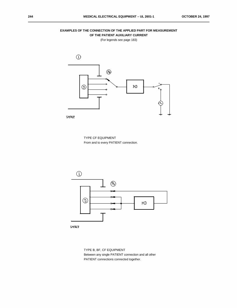
244 MEDICAL ELECTRICAL EQUIPMENT – UL 2601-1 OCTOBER 24, 1997
EXAMPLES OF THE CONNECTION OF THE APPLIED PART FOR MEASUREMENTOF THE PATIENT AUXILIARY CURRENT
(For legends see page 183)
TYPE CF EQUIPMENTFrom and to every PATIENT connection.
TYPE B, BF, CF EQUIPMENTBetween any single PATIENT connection and all otherPATIENT connections connected together.
OCTOBER 24, 1997 MEDICAL ELECTRICAL EQUIPMENT – UL 2601-1 245
APPENDIX L
REFERENCES – PUBLICATIONS MENTIONED IN THIS STANDARD
IEC Standards Date Title
Publication 65 1985 Safety requirements for mains operated electronic and related apparatus for household and similargeneral use.Fifth edition 1985, incorporatingAmendment No. 1 (1978).Amendment No. 2 (1981).
Publication 68-2-2 1974 Basic environmental testing procedures.Part 2-2: Test B, Dry heat.
Publication 73 1984 Colors of indicator lights and push-buttons.
Publication 79 – Electrical apparatus for explosive gas atmospheres.
Publication 79-2 1983 Electrical apparatus for explosive gas atmospheres.Part 2: Electrical apparatus - type of protection "p".
Publication 79-5 1967 Electrical apparatus for explosive gas atmospheres.Part 5: Sand-filled apparatus.
Publication 79-6 1968 Electrical apparatus for explosive gas atmospheres.Part 6: Oil-immersed apparatus.
Publication 85 1984 Thermal evaluation and classification of electrical insulation.
Publication 112 1979 Method for determining the comparative and the proof tracking indices of solid insulating materials under moist conditions.
Publication 127 1974 Cartridge fuse-links for miniature fuses.
Publication 227 – Polyvinyl chloride insulated cables of rated voltages up to andincluding 450/750 V.Amendment No. 1(1985).
Publication 241 1968 Fuses for domestic and similar purposes.
Publication 245 – Rubber insulated cables of rated voltages up to and including450/750 V.
Publication 245-4 1980 Rubber insulating cables of rated voltages up to and including 450/750 V.Part 4: Cords and flexible cords.
Publication 252 1975 A.C. motor capacitors.
Publication 309 – Plugs, socket-outlets and couplers for industrial purposes.
246 MEDICAL ELECTRICAL EQUIPMENT – UL 2601-1 OCTOBER 24, 1997
Publication 320 1981 Appliance couplers for household and similar general purposes.
Publication 328 1972 Switches for appliances.
Publication 355-1 1970 Safety of household and similar electrical appliances.Part 1: General requirements.
Publication 336 1982 Characteristics of focal spots in diagnostic X-ray tube assembliesfor medical use.
Publication 348 1978 Safety requirements for electronic measuring apparatus.
Publication 364-4-41 1982 Electrical installations of buildings. Part 4: Protection for safety.Chapter 41: Protection against electric shock.
Publication 384-14 1981 Fixed capacitors for use in electronic equipment.Part 14: Sectional specification:Fixed capacitors for radio interference suppression. Selection of methods of test and generalrequirements.
Publication 417 – Graphical symbols for use on equipment. Index, survey and compilation of the single sheets.
Publication 445 1973 Identification of apparatus terminals and general rules for a uniform system of terminal marking,using an alphanumeric notation.
Publication 447 1974 Standard directions of movement for actuators which control the operation of electrical apparatus.
Publication 513 1976 Basic aspects of the safety philosophy of electrical equipment used in medical practice.
Publication 529 1976 Classification of degrees of protection provided by enclosures.
Publication 536 1976 Classification of electrical and electronic equipment with regard to protection against electricshock.
Publication 601-1 1977 Safety of medical electrical equipment.Part l: General requirements.First edition 1977.Amendment No. 1(1984)
Publication 664 1980 Insulation co-ordination within low-voltage systems including clearances and creep age distancesfor equipment.
Publication 695 – Fire hazard testing.
Publication 707 1981 Methods of test for the determination of the flammability of solid electrical insulating materials whenexposed to an igniting source.
OCTOBER 24, 1997 MEDICAL ELECTRICAL EQUIPMENT – UL 2601-1 247
Publication 742 1983 Isolating transformers and safety isolating transformers: Requirements.
Publication 878 1988 Graphical symbols for electrical equipment in medical practice.
ISO Publications
ISO 32 1977 Gas cylinders for medical use - Marking for identification of content.
ISO 407 1983 Small medical gas cylinders - Yoke-type valve connections.
ISO 471 1983 Rubber - Standard temperatures, humidities and times for the conditioning and testing of test pieces.
ISO 780 1985 Packaging - Pictorial marking for handling of goods.
ISO 1853 1975 Conducting and antistatic rubbers - Measurement of resistivity.
ISO 2878 1987 Rubber, vulcanized - Antistatic and conductive products -Determination of electrical resistance.
ISO 2882 1979 Rubber, vulcanized - Antistatic and conductive products for hospital use - Electrical resistance limits.
ISO 8185 1988 Humidifiers for medical use - Safety requirements.
248 MEDICAL ELECTRICAL EQUIPMENT – UL 2601-1 OCTOBER 24, 1997
INDEX OF DEFINED TERMS
ACCESS COVER 2.1.1 MAINS PART 2.1.12ACCESSIBLE METAL PART 2.1.2 MAINS PLUG 2.7.11ACCESSIBLE PART 2.1.22 MAINS TERMINAL DEVICE 2.7.12ACCESSORY 2.1.3 MAINS VOLTAGE 2.4.2ACCOMPANYING DOCUMENTS 2.1.4 MAXIMUM PERMISSIBLE WORKINGPRESSURE 2.11.2ADJUSTABLE SETTING 2.9.1 MEDICAL ELECTRICAL EQUIPMENT(of a control or limiting device) (herein after referred to as EQUIPMENT)AIR CLEARANCE 2.3.1APPLIANCE COUPLER 2.7.1 MINIMUM BREAKING LOAD 2.11.3APPLIANCE INLET 2.7.2 MOBILE EQUIPMENT 2.2.16APPLIED PART 2.1.5 MODEL OR TYPE REFERENCE (type number) 2.12.2AUXILIARY MAINS SOCKET-OUTLET 2.7.4 NOMINAL (value) 2.12.3BASIC INSULATION 2.3.2 NORMAL CONDITION 2.10.7
CATEGORY AP EQUIPMENT 2.2.2CATEGORY APG EQUIPMENT 2.2.3 OPERATOR 2.12.17CLASS I EQUIPMENT 2.2.4 OVER-CURRENT RELEASE 2.9.7CLASS 11 EQUIPMENT 2.2.5COLD CONDITION 2.10.1 PATIENT 2.12.4CONDUCTIVE CONNECTION 2.7.5 PATIENT AUXILIARY CURRENT 2.5.4CONTINUOUS OPERATION 2.10.2 PATIENT CIRCUIT 2.1.15CONTINUOUS OPERATION PATIENT LEAKAGE CURRENT 2.5.6 WITH INTERMITTENT LOADING 2.10.3 PERMANENTLY INSTALLED EQUIPMENT 2.2.17CONTINUOUS OPERATION WITH PORTABLE EQUIPMENT 2.2.18 SHORT-TIME LOADING 2.10.4 POTENTIAL EQUALIZATION CONDUCTOR 2.6.6CREEPAGE DISTANCE 2.3.3 POWER SUPPLY CORD 2.7.17
PRESSURE (overpressure) 2.11.4DETACHABLE POWER SUPPLY CORD 2.7.6 PROPERLY INSTALLED 2.10.9DIRECT CARDIAC APPLICATION 2.2.7 PROTECTIVE COVER 2.1.17DOUBLE INSULATION 2.3.4 PROTECTIVE EARTH CONDUCTOR 2.6.7DRIP-PROOF EQUIPMENT 2.2.9 PROTECTIVE EARTH TERMINAL 2.6.8DUTYCYCLE 2.10.5 PROTECTIVELY EARTHED 2.6.9EARTH LEAKAGE CURRENT 2.5.1 RATED (value) 2.12.8EMERGENCY TROLLEY 2.12.14 REINFORCED INSULATION 2.3.7ENCLOSURE 2.1.6ENCLOSURE LEAKAGE CURRENT 2.5.2 SAFE WORKING LOAD 2.11.5EQUIPMENT(see Sub-clause 2.2.15) 2.2.11 SAFETY DEVICE 2.11.6EXTERNAL TERMINAL DEVICE 2.7.7 SAFETY EXTRA-LOW VOLTAGE (SELV)2.4.3
SAFETY EXTRA-LOW VOLTAGE TRANSFORMER2.8.3F-TYPE ISOLATED(FLOATING) APPLIED PART (F-TYPE APPLIED PART) 2.1.7 SAFETY FACTOR 2.11.8FIXED EQUIPMENT 2.2.12 SAFETY HAZARD- 2.12.18FIXED MAINS SOCKET-OUTLET 2.7.8 SELF-RESETTING THERMAL CUT-OUT 2.9.10FIXED SETTING (of a control or limiting device) 2.9.4 SELV (SAFETY EXTRA-LOW VOLTAGE) 2.4.3FLAMMABLE ANAESTHETIC MIXTURE WITH AIR 2.12.15 SERIAL NUMBER 2.12.9FLAMMABLE ANAESTHETIC MIXTURE WITH SHORT-TIME OPERATION 2.10.10 OXYGEN OR NITROUS OXIDE 2.12.16 SIGNAL INPUT PART 2.1.18FUNCTIONAL EARTH CONDUCTOR 2.6.3 SIGNAL OUTPUT PART 2.1.19FUNCTIONAL EARTH TERMINAL 2.6.4 SINGLE FAULT CONDITION 2.10.11
SPLASH-PROOF EQUIPMENT 2.2.20HAND-HELD EQUIPMENT 2.2.13 STATIC LOAD 2.11.7HIGH VOLTAGE 2.4.1 STATIONARY EQUIPMENT 2.2.21HYDRAULIC TEST PRESSURE 2.11.1 SUPPLEMENTARY INSULATION 2.3.8
SUPPLY EQUIPMENT 2.1.21INTERCONNECTION TERMINAL DEVICE 2.7.9 SUPPLY MAINS 2.12.10INTERMITTENT OPERATION 2.10.6INTERNAL ELECTRICAL POWER SOURCE 2.1.9 TERMINAL DEVICE 2.7.16INTERNALLY POWERED EQUIPMENT 2.2.29 THERMAL CUT-OUT 2.9.12
THERMOSTAT 2.9.13LEAKAGE CURRENT 2.5.3LIVE 2.1.10 TOOL 2.12.12
TOTAL LOAD 2.11.9MAINS CONNECTOR 2.7.10 TRANSPORTABLE EQUIPMENT 2.2.23
OCTOBER 24, 1997 MEDICAL ELECTRICAL EQUIPMENT – UL 2601-1 249
TYPE B EQUIPMENT 2.2.24 USER 2.12.13TYPE BF EQUIPMENT 2.2.25TYPE CF EQUIPMENT 2.2.26 WATERTIGHT EQUIPMENT 2.2.28

250 MEDICAL ELECTRICAL EQUIPMENT – UL 2601-1 OCTOBER 24, 1997
No Text On This Page
OCTOBER 24, 1997 MEDICAL ELECTRICAL EQUIPMENT – UL 2601-1 251
IEC 601-1
1988
AMENDMENT 1
1991-11
Amendment 1
Medical Electrical Equipment
Part 1:General requirements for safety
252 MEDICAL ELECTRICAL EQUIPMENT – UL 2601-1 OCTOBER 24, 1997
FOREWORD
This amendment has been prepared by Sub-Committee 62A: Common aspects of electrical equipment used in medical practice of IECTechnical Committee No. 62: Electrical equipment in medical practice.
The text of this amendment is based on the following documents:
Six month's rule Report on voting
62A(CO)36 62A(CO)39
Full information on the voting for the approval of this amendment can be found In the Voting Report indicated in the above table.
___________________
INTRODUCTION
This amendment contains a first series of revisions to IEC Publication 601-1 (second edition, 1988): Medical electrical equipment, Part 1:General requirements for safety.
Aware of the need and the urgency for a General Standard covering electromedical equipment, the majority of National Committees voted in1977 in favour of the first edition of IEC 601-1, based on a draft which at the time represented a first approach to the problem.
The extent of the scope, the complexity of the equipment concerned, and the specific nature of some of the protective measures and thecorresponding tests for verifying them had required years of effort in order to prepare that first Standard, which served as a universal referencesince Its publication.
However, its sequent application revealed room for Improvement, and careful work of revision subsequently undertaken and continued overa number of years resulted in the second edition (1988). The present publication contains further modifications.
The General Standard contains requirements of safety which are generally applicable to MEDICAL ELECTRICAL EQUIPMENT. For certaintypes of Equipment, these requirements are supplemented or modified by the special requirements of a Particular Standard. Where ParticularStandards exist, the General Standard should not be used alone. Special care Is required in applying the General Standard to EQUIPMENTfor which no Particular Standard exists.
In some countries EQUIPMENT may only be certified as complying with the Standard if either a Particular Standard or an authorized documentbased on the General Standard is available, stating which clauses are applicable for the EQUIPMENT concerned.

OCTOBER 24, 1997 MEDICAL ELECTRICAL EQUIPMENT – UL 2601-1 253
Page 40
CONTENTS
Replace Clauses 8 and 9 by the following:
8 Basic safety categories . . . . . . . . . . . . . . . . . . . . . . . . . . . . . . . . . . . . . . . . . . . . . . . . . . . . . . . . . . . . . . . . . . . . . . . . . . . . . . . . . . . . . 74
9 Removable protective means . . . . . . . . . . . . . . . . . . . . . . . . . . . . . . . . . . . . . . . . . . . . . . . . . . . . . . . . . . . . . . . . . . . . . . . . . . . . . . . . 74
Page 42
Number of tables
Replace last XIX by XX, Test current for mains supply transformers . . . . . . . . . . . . . . . . . . . . . . . . . . . . . . . . . . . . . . . . . . . . . . . . . . . 151
Page 42
Replace (top left) "Clause" by "Figure".
Page 45
PREFACE
Replace the fifth line from the bottom by the following:
Explanations, advice, introductions, general statements, exceptions and references: in smaller roman type.
Replace the fourth line from the bottom by the following:
Test specifications and headings of sub-clauses: In Italic type
Page 47
SECTION ONE
*1.3 Particular Standards
Replace the existing text by the following:
A Particular Standard takes priority over this General Standard.
254 MEDICAL ELECTRICAL EQUIPMENT – UL 2601-1 OCTOBER 24, 1997
Page 47
2 Terminology and definitions
2.2.9 DRIP-PROOF EQUIPMENT
Replace the existing text by the following:
EQUIPMENT provided with an ENCLOSURE preventing entry of such an amount of falling liquid as might interfere with the safe operationof the EQUIPMENT (see Sub-clause 44.6).
2.2.20 SPLASH-PROOF EQUIPMENT
Replace the existing text by the following:
EQUIPMENT provided with an ENCLOSURE preventing entry of such an amount of liquid, splashed from any direction, as might interferewith the safe operation of the EQUIPMENT (see Sub-clause 44.6).
Page 51
2.2.23 TRANSPORTABLE EQUIPMENT
Replace the first paragraph of the existing text by the following:
EQUIPMENT which is intended to be moved from one place to another whether or not connected to a supply and without an appreciablerestriction of range.
Page 54
2.7.4 AUXILIARY MAINS SOCKET-OUTLET
Replace the existing text by the following:
Socket-outlet with MAINS VOLTAGE on EQUIPMENT, accessible without the use of a TOOL and intended for provision of mains supplyto other EQUIPMENT or to other separate parts of the EQUIPMENT.
Page 54
2.7.8 FIXED MAINS SOCKET OUTLET
Modify the title to read:
FIXED MAINS SOCKET-OUTLET
OCTOBER 24, 1997 MEDICAL ELECTRICAL EQUIPMENT – UL 2601-1 255
Page 56
2.9.13 THERMOSTAT
Replace the existing text by the to following:
A cycling temperature-sensing control, which is intended to keep a temperature between two particular values under normal operatingconditions and which may have provision for setting by the OPERATOR.
Page 57
2.10.8 NORMAL USE
Replace the existing text by the following:
Operation, including routine inspection and by the OPERATOR, and stand-by, according to the instructions for use.
Page 58
2.12.4 PATIENT
Replace the existing text by the following:
Living being (person or animal) undergoing medical or dental investigation or treatment.
Page 59
3 General requirements
3.6
Add a new item as follows:
j) leakage of liquid (see Sub-clause 44.4).
Page 64
6 Identification, marking and documents
*6.1 Marking on the outside of EQUIPMENT or EQUIPMENT PARTS
Delete the asterisk in front of the sub-clause number.
256 MEDICAL ELECTRICAL EQUIPMENT – UL 2601-1 OCTOBER 24, 1997
Pages 64 to 68
6.1, top right
Delete the asterisk in front of the sub-clause number.
Page 66
6.1 I), third dash:
The modification in the first paragraph applies to the French text only.
Add a second paragraph as follows:
For clear differentiation from symbol 2, symbol 1 shall not be applied in such a way as to give the impression of being Inscribed within asquare.
The existing second paragraph becomes the third paragraph.
Page 67
6.1 v) The modification applies to the French text only.
6.1 y) Earth terminals
Replace at the first dash:
18.e)) by 18e))
Page 68
6.2 b)
Add the following paragraph:
For heating elements or lampholders designed for use with heating lamps not intended to be changed by the OPERATOR and which can bechanged only with the use of a TOOL, an identifying marking referring to Information stated in the ACCOMPANYING DOCUMENTS issufficient.
OCTOBER 24, 1997 MEDICAL ELECTRICAL EQUIPMENT – UL 2601-1 257
Page 70
6.5 c)
Replace the third and fourth dashes by the following:
– POTENTIAL EQUALIZATION CONDUCTORS (see Sub-clause 18 e));
– Functional earth conductors as specified in Sub-clause 18 I).
Page 73 and 74
7.1
Replace the heads of paragraphs a), b) and c) by dashes.
SECTION TWO
Page 75
10.2.2 a), fifth dash
Delete paragraphs 2, 3 and 4 (they are hereafter reinstated in Appendix A), and add an asterisk In front of the Sub-clause number.
10.2.2 b)
Replace the compliance paragraph by the following:
Compliance with the condition of Clause 10 is checked by application of the tests of this Standard.
SECTION THREE
Page 76
14.1 CLASS I EQUIPMENT
and
14.2 CLASS II EQUIPMENT
Delete the sentences:
In addition to the information given In Sub-clause 2.2.4 (and 2.2.5 respectively), the following applies:
258 MEDICAL ELECTRICAL EQUIPMENT – UL 2601-1 OCTOBER 24, 1997
Page 77
14.4 CLASS I and CLASS II EQUIPMENT
Delete the asterisk in front of the sub-clause number.
Page 77 – 79
15. last paragraph (compliance)
Replace the first sentence by the following:
EQUIPMENT is operated at RATED voltage and then de-energized.
16 a)
Replace the first paragraph by the following:
EQUIPMENT shall be so constructed and enclosed that there is protection against contact with LIVE parts, and with parts which can becomeLIVE in SINGLE FAULT CONDITIONS.
16 a) 5)
Add an asterisk In front of the sub-clause number.
Page 79
16 a) (compliance)
The modification applies to the French text only.
Page 80
16 e)
Add an asterisk in front of the sub-clause number.
OCTOBER 24, 1997 MEDICAL ELECTRICAL EQUIPMENT – UL 2601-1 259
Page 86
*19.2 SINGLE FAULT CONDITIONS
Replace the asterisk in front of this sub-clause number by an asterisk in front of Sub-clause 19.2 a).
(Delete also the asterisk at the top of page 89).
Page 86 and 87
19.2 b), first dash
Replace the third line by the following:
This requirement shall not apply in the following cases:
19.2 b)
Replace the two series of sub-numbering 1), 2), 3), and 1), 2), by five bullets.
19.2 b), third dash
Replace the first paragraph by the following:
– A voltage equal to 110 % of the highest RATED MAINS VOLTAGE applied between earth and any ACCESSIBLEMETAL PARTS not PROTECTIVELY EARTHED.
Page 95
20.1 A-e, second paragraph
Delete the following sentence:
This insulation shall be DOUBLE INSULATION Or REINFORCED INSULATION.
20.1 A-e, last paragraph
The modification applies to the French text only.
Page 98
Table V, second line
The modification applies to the French text only

260 MEDICAL ELECTRICAL EQUIPMENT – UL 2601-1 OCTOBER 24, 1997
SECTION FOUR
Page 102
21.3
Replace the last two paragraphs by the following:
Foot rests and chairs shall be tested by the same procedure, but the test force shall be twice the specified maximum normal load or, if sucha load is not specIfied, the test force shall be 2,7 kN. The test force shall be evenly distributed over an area of 0, 1 m surface area for one
2
minute.
At the completion of the test, foot rests and chairs shall show no damage resulting in a SAFETY HAZARD.
Page 102 and 103
*21.6 Replace the existing text by the following:
*21.6 PORTABLE and MOBILE EQUIPMENT shall be capable of withstanding the stresses caused by rough handling.
Compliance is checked by the following tests:
a) PORTABLE EQUIPMENT is lifted to a height as Indicated In Table VIII above a 50 mm thick hardwood board (see Sub-clause 21.5). The other dimensions of the board shall be at least 1,5 times those of the EQUIPMENT and it shall lieflat on a rigid (concrete) base. The EQUIPMENT is dropped three times from each attitude in which it may be placedin NORMAL USE.
TABLE VIIIDrop height
Mass of EQUIPMENT (kg) Drop height (cm)
Up to and including 10 5
More than 10 up to and including 50 3
More than 50 2
After the test EQUIPMENT shall comply with the requirements of this Standard.
b) MOBILE EQUIPMENT is propelled, by a force actIng at a point as near floor level as possible, in its normal directionof travel at a velocIty of 0,4 m/s, ± 0,1 m/s, or for self-propelled EQUIPMENT at its maximum velocity, over adescending step 20 mm high, which is rigidly attached to an otherwise flat floor.
The test is performed 20 times after which the EQUIPMENT shall comply with the requirements of this Standard.

OCTOBER 24, 1997 MEDICAL ELECTRICAL EQUIPMENT – UL 2601-1 261
This test need not be performed on EQUIPMENT and EQUIPMENT parts tested according to Sub-clauses 21.5 or 21.6 a).
Page 103
22.2
Replace the last paragraph by the following:
Compliance is checked by inspection.
SECTION FIVE
Page 107 and 108
29.2
Replace the third and fourth paragraphs by the following:
Controls and adjustments, internal and external, provided for the purpose of altering the value of the relevant HIGH VOLTAGE source(s)in the EQUIPMENT, are set at the position resulting in the maximum emission of X-radiation. Single failures of components causing the leastfavorable conditIons are simulated in turn.
36 Electromagnetic compatIbIlIty
Add an asterisk in front of the clause number.
SECTION SIX
Page 108
Replace the prefatory note on the third line by the following:
NOTE – This section has been partly re-written and re-numbered.
37.5 FLAMMABLE ANAESTHETIC MIXTURE WITH AIR
Replace the existing text by the following:
Where a FLAMMABLE ANAESTHETIC MIXTURE WITH AIR OCCURS because of a leakage or discharge of a FLAMMABLEANAESTHETIC MIXTURE WITH OXYGEN OR NITROUS OXIDE from an ENCLOSURE, it is considered to propagate to a volumeSurrounding the leakage or discharge point at a distance from 5 cm to 25 cm from such a point.
262 MEDICAL ELECTRICAL EQUIPMENT – UL 2601-1 OCTOBER 24, 1997
Page 116
*41.5 Humidifiers
Replace the existing text by the following:
41.5 Humidifiers
See ISO 8185.
SECTION SEVEN
Page 117
Table Xa
In the main box replace the second and third lines by the following:
– of Class A material 2),3)..........
– of Class B material 2),3)..........
Page 124
44.4 Leakage
Replace the title and the first paragraph by the following:
*44.4 Leakage
EQUIPMENT shall be so constructed that liquid which might escape in a SINGLE FAULT CONDITION does not cause a SAFETY HAZARD.
Page 124
44.4
Replace the last paragraph by the following:
After these procedures, the EQUIPMENT shall comply with all the requirements of this Standard for SINGLE FAULT CONDITIONS.
OCTOBER 24, 1997 MEDICAL ELECTRICAL EQUIPMENT – UL 2601-1 263
44.6 Ingress of liquids
The modification applies to the French text only.
44.7 Cleaning, sterilization and disinfection
Replace in the third paragraph, first line:
disinfection by disinfection
Page 126
45.2
Replace the first three paragraphs by the following:
If a pressure vessel has a PRESSURE volume greater than 200 kPa x I, and PRESSURE greater than 50 kPa, it shall withstand theHYDRAULIC TEST PRESSURE.
Compliance is checked by the following tests:
The test PRESSURE shall be the MAXIMUM PERMISSIBLE WORKING PRESSURE multiplied by a factor obtained from Figure 38.
45.3
Replace the first paragraph by the following:
The maximum PRESSURE to which a part can be subjected in NORMAL CONDITION and SINGLE FAULT CONDITION shall not exceedthe MAXIMUM PERMISSIBLE WORKING PRESSURE for the part.
SECTION NINE
Page 129
52.4.1
Replace the third dash by the following:
– temperatures exceeding the maximal values shown In table XI, during the tests of sub-clauses 52.5.10 d) through52.5.10 h). These temperatures apply for an ambient temperature of 25EC.
264 MEDICAL ELECTRICAL EQUIPMENT – UL 2601-1 OCTOBER 24, 1997
Page 132
52.5.8
Replace the last two paragraphs by the following:
Temperatures shall not exceed the limits of Table XII.
Page 133
Table XII, bottom left-hand box
Replace the first two lines by the following:
Other EQUIPMENT
– if impedance-protected, maximum value
Page 135
52.5.10 g)
The modification applies to the French text only.
SECTION TEN
Page 137
56.1 b)
Add an asterisk in front of the sub-clause number.
Page 139
56.6 b) Allowable temperature range
Replace the title by the following:
Temperature settings

OCTOBER 24, 1997 MEDICAL ELECTRICAL EQUIPMENT – UL 2601-1 265
56.7 INTERNAL ELECTRICAL POWER SOURCE
Replace the existing title by the following:
Batteries
Page 140
56.7 b) Connection
Replace items 1) and 2) of the compliance paragraph by the following:
1) Establishing whether there is a possibility of making an incorrect battery connection.
2) Where such a possibility exists, establishing the effect of an incorrect battery connection.
Page 141
56.10 c) Limitation of movement
Replace the first paragraph by the following:
Stops of adequate mechanical strength shall be provided on rotating or movable parts of controls, where necessary to prevent an unexpectedchange from maximum to minimum, or vice-versa, of the controlled parameter where this could produce a SAFETY HAZARD.
56.11 b) Mechanical strength
Replace the compliance paragraph by the following:
Compliance is checked by application to the foot-operated control device, in its position of NORMAL USE, of an actuating force of 1350 Nfor 1 min. The force is applied over an area of 625 mm . There shall be no damage to the device resulting in a SAFETY HAZARD and
2
indent the new paragraph so that It applies to the second dash only.
Page 143
57.2 e)
Replace the second and third paragraphs by the following:
This requirement does not apply to EMERGENCY TROLLEYS, on which however the number of such sockets shall be limited to 4.
These AUXILIARY MAINS SOCKET-OUTLETS shall be properly marked (see Sub-clause 6.1 k)).

266 MEDICAL ELECTRICAL EQUIPMENT – UL 2601-1 OCTOBER 24, 1997
Page 145
57.4 a) Cord anchorages
Replace Items 2) and 3) by the following:
2) of metal, insulated from conductive ACCESSIBLE PARTS not PROTECTIVELY EARTHED by SUPPLEMENTARYINSULATION, or
3) of metal provided with an insulating lining, if otherwise a total insulation failure of the POWER SUPPLY CORD couldrender LIVE conductive ACCESSIBLE PARTS not PROTECTIVELY EARTHED. This lining shall be fixed to the cordanchorage, unless it is a flexible bushing which forms part of the cord guard specified in this sub-clause, and shallcomply with the requirements for BASIC INSULATION.
Page 146
57.4 a)
Replace the last five paragraphs by the following:
After the tests, the cord sheath shall not have been longitudinally displaced by more than 2 mm and the conductor ends shall not have movedover a distance of more than 1 mm from their normally connected position.
CREEPAGE DISTANCES and AIR CLEARANCES shall not be reduced below the values specified in Sub-clause 57.10.
For the measurement of the longitudinal displacement, a mark shall be made on the cord sheath while it is subjected to the first pull, at adistance of approximately 2 cm from the cord anchorage or other suitable point between the cord anchorage and the test apparatus.
This displacement of the mark on the cord sheath in relation with the cord anchorage or another point shall be measured while the cord issubjected to the last pull.
It shall not be possible to push the cord into EQUIPMENT to such an extent that the cord, or internal parts of the EQUIPMENT, could bedamaged.
Page 149
57.9.1 Overheating, second dash
Replace the first paragraph by the following:
Where protective devices external to the transformer or transformer ENCLOSURE provide the protection against overheating, e.g. fuses,OVER-CURRENT RELEASES, THERMAL CUT-OUTS, these devices shall be connected in such a way that failure of any component otherthan wiring interposed between the protective devices and the transformer cannot render the protective devices inoperative.
OCTOBER 24, 1997 MEDICAL ELECTRICAL EQUIPMENT – UL 2601-1 267
Page 151
57.9.1 b) Overload, fourth dash, third bullet
Replace the existing text by the following:
! If the current under short-circuit condition is smaller than the test current specified above, the transformer section orwinding is short-circuited until steady thermal condition is attained.
57.9.1 b) Overload, fourth dash, fifth bullet, first line
Replace:
! OVERCURRENT by OVER-CURRENT
Page 151
57.9.1 b)
Replace:
OVERCURRENT by OVER-CURRENT
Page 153
57.9.2
Replace the sixth dash by the following:
– InItially not more than half the prescribed voltage shall be applied, then It shall be raised over a period of 10 s to the fullvalue, which is then maintained for 1 min, after which the voltage shall be reduced gradually and switched off.
Page 155
57.10 b), third dash
Delete the second paragraph.
Page 156
Table XVI
Replace in the first row the second figure, 34, by the following:
36
268 MEDICAL ELECTRICAL EQUIPMENT – UL 2601-1 OCTOBER 24, 1997
Page 157
59.1 a) Mechanical protection
The modification applies to the French text only.
FIGURES
Page 167
Figure 10
Replace the second paragraph of the caption by the following:
Measuring supply circuit with one side of the SUPPLY MAINS at approximately earth potential (see Sub-clause 19.4 b)).
Page 172
Figure 16
The modification applies to the French text only.
Page 173
Figure 17
Replace in the measurement procedure, above the caption, the first two paragraphs by the following:
Measure with MD1 and MD2 with S closed8and S , S and S closed and under all1 2 3possible combinations of positions ofS , S , S and S (NORMAL CONDITION).5 10 11 12
Measure with MD2 with s open (SINGLE8FAULT CONDITION) if the specified power supply is PROTECTIVELY EARTHED and with S , S1 2and S closed under all possible combInations 3of positions of S , S , S and S .5 10 11 12
OCTOBER 24, 1997 MEDICAL ELECTRICAL EQUIPMENT – UL 2601-1 269
Page 174
Figure 18
The modification applies to the French text only.
Pages 174 and 175
Figures 18 and 19, as the voltmeter located in the upper part of the figure is identIfied V2,likewise identify V1 the voltmeter In the lower part.
Figure 19 (first three paragraphs above the title)
The modification applies to the French text only.
Page 176
Figure 20 (text above the title)
The modification applies to the French text only.
270 MEDICAL ELECTRICAL EQUIPMENT – UL 2601-1 OCTOBER 24, 1997
Page 177
Figure 21 (text above title)
The modification applies to the French text only.
Page 178
Figure 22
The modification applies to the French text only.
Page 180
Figure 24
Delete, in the figure, the identification V2 in front of the voltmeter.
Page 182
Figure 26 (text above title)
The modification applies to the French text only.
Page 183 (folded)
Legends of symbols for Figures 10 to 27
Replace, in fourth line from the bottom, the existing text by the following:
MD(1, 2, 3, 4) Measuring devices (see Figure 15)
Add a new Item as follows:
R Impedance for protection of user of test apparatus.
OCTOBER 24, 1997 MEDICAL ELECTRICAL EQUIPMENT – UL 2601-1 271
APPENDIX A
Page 202
A1.2 Guidance to the second edition
Replace, in the fourth dash, the existing text by the following:
– The insulation between an F-TYPE APPLIED PART and the ENCLOSURE of the EQUIPMENT was reviewed todistinguish the case where such an APPLIED PART would contain voltages which would make the PATIENT LIVE when theinsulation would become defective (see new categories B-d and B-e).
Page 204
A1.5 Protection against hazards from unwanted or excessive radiation
Delete the sub-clause number A1.5.1 (keep the text) and delete completely sub-clause A1.5.2 (transferred as rationale for clause 36).
Ex Sub-clause A1.5.1
Replace the last two paragraphs by the following:
Their evaluation is possible only by adequate study of operating methods and duration of operation of EQUIPMENT and positioning ofOPERATOR and assistants, because application of worst case conditions would give rise to situations which might hamper proper diagnosisor treatment.
Recent ICRP publications also instruct the OPERATOR in methods for the restriction of intentional irradiation.
Page 207
A1.9 Abnormal operation and fault conditions causing electric shock, overheating and/or mechanical damage; environmental tests
Replace the existing title by the following:
A1.9 Abnormal operation and fault conditions; environmental tests
Page 207
A2 Rationale to particular clauses and sub-clauses
Sub-clause 1.3 e)
Replace the existing text by the following:
extension and limitation of environmental conditions
OCTOBER 24, 1997 MEDICAL ELECTRICAL EQUIPMENT – UL 2601-1 272
Page 211
Sub-clause 6.8.1
The modification applies to the French text only.
Sub-clause 10.2.2
The modification applies to the French text only.
Page 212
Sub-clause 10.2.2, Literature
Replace the third paragraph by the following:
– Modern Power SystemsNeuenswonderpage 183, Measurement of Zero Sequence.
Page 212
Add a new sub-clause as follows:
Sub-clause 10.2.2 a)
An alternating voltage is considered in practice to be sinusoidal it any instantaneous value of the waveform concerned differs from theinstantaneous value of the ideal waveform at the same moment by no more than ±5% of the peak value of the ideal waveform, unless statedotherwise;
A polyphase voltage system is considered to be symmetrical if neither the magnitude of its negative sequence components nor the magnitudeof its zero sequence components exceeds 2 % of the magnitude of its positive sequence components;
A polyphase supply system is considered to be symmetrical if, when supplied from a symmetrical voltage system, the resulting current systemis symmetrical. That is, the magnitude of neither the negative sequence current components nor the zero sequence current componentsexceeds 5 % of the magnitude of the positive sequence current components.
Page 212
Sub-clause 14.4
Delete the sub-clause number and the test (transferred to 16 e)).
OCTOBER 24, 1997 MEDICAL ELECTRICAL EQUIPMENT – UL 2601-1 273
Clause 16
Replace the fifth dash by the following:
– a screwdriver for adjustment of a preset control by the OPERATOR, simulated by an inserted metal rod;
Page 213
Sub-clause 16 c)
Replace the first paragraph by the following:
The compliance test for the protective earthing of ACCESSIBLE METAL PARTS of EQUIPMENT (sub-clause 18 f)) is conducted with acurrent between 10 A and 25 A provided by a source with a sufficient low voltage (not exceeding 6 V). The current is maintained for at least5 s. The reasons for these requirements are that the connection can only perform its protective function if it is able to carry the fault currentresulting from a failure in BASIC INSULATION.
Page 214
Add a new sub-clause as follows:
Sub-clause 16 e)
The combination of isolated supply and the restricted voltage is regarded as an additional protective measure against electric shock hazard.
Page 214
Sub-clause 18 a)
Replace the first paragraph by the following:
Generally, ACCESSIBLE METAL PARTS OF CLASS I EQUIPMENT shall be connected permanently and with sufficiently low impedanceto the PROTECTIVE EARTH TERMINAL.
Sub-clause 18 a), legend of figure
Replace the last line by the following:
R = Test resistance (1KS)T
274 MEDICAL ELECTRICAL EQUIPMENT – UL 2601-1 OCTOBER 24, 1997
Page 216
ENCLOSURE LEAKAGE CURRENT
Replace the fifth dash by the following:
The ENCLOSURE LEAKAGE CURRENT of TYPE CF EQUIPMENT in NORMAL CONDITION was raised to the same level as for TYPESB and BF EQUIPMENT because such EQUIPMENT may be used simultaneously on a PATIENT.
Page 223
Add a new clause as follows:
Clause 36
High frequency radiation above 0,15 MHz is normally directly harmful only if produced at substantial energy levels, for example, by diathermyand surgical EQUIPMENT. However, this radiation may, even when produced at fairly low energy levels, influence the function of sensitiveelectronic devices and cause interference in radio and radio and television reception.
Constructional requirements can hardly be given, but limits and measuring methods have been described in CISPR publications.
The sensitivity of EQUIPMENT to external interference (electromagnetic field, perturbations of the supply voltage) is under consideration.
Page 223
Delete Sub-clause 41.5
Add a new Sub-clause 41.5.
Sub-clause 44.4
Leakage is considered as a SINGLE FAULT CONDITION
Page 224
Sub-clause 45.2
Replace the first paragraph by the following:
It is assumed that if the PRESSURE X volume is equal to or smaller than 200 kPa x 1 or the PRESSURE is equal to or smaller than 50 kPa,a hydraulic test is not necessary.
OCTOBER 24, 1997 MEDICAL ELECTRICAL EQUIPMENT – UL 2601-1 275
Sub-clause 45.2
Add a new paragraph as follows:
The deletion of national references in the amended text avoids subordinating the requirements of the Standard to those of local regulations.The EQUIPMENT will sometimes have to satisfy both, or the more demanding, assuming that there are no local regulations which conflictwith the Standard.
Page 225
Add a new sub-clause as follows:
Sub-clause 56.1 b)
Normally compliance with this requirement is checked for components in the MAINS PART and APPLIED PART.
Page 226
Sub-clause 57.9
The modification applies to the French text only.
Page 227
Sub-clause 59.1 e)
The modification applies to the French text only.
APPENDIX C
Page 230
Sub-clause C 17 – Electromagnetic compatibility
Replace the existing text by the following:
See CISPR recommendations and the rationale for Clause 36.

276 MEDICAL ELECTRICAL EQUIPMENT – UL 2601-1 OOCTOBER 24, 1997
APPENDIX K
Page 243
Delete the title at the top of the page and add the following text between the two figures inthe middle of the page:
EXAMPLE FOR THE CONNECTION OF THE APPLIED PARTFOR MEASUREMENT OF THE PATIENT AUXILIARY CURRENT
(see legends page 183)
APPENDIX L
Page 246
Replace Publication 355-1, 1970 by:Publication 335-1, 1976.
OCTOBER 24, 1997 MEDICAL ELECTRICAL EQUIPMENT – UL 2601-1 277
IEC 601-1
1988
AMENDMENT 2
1995-03Amendment 2
Medical Electrical Equipment
Part 1:General requirements for safety
Amendment 2 requirements become effective February 6, 1999except for subclause 6.3.9 g) which becomes effective February 6, 2004
Note: It is UL's policy that Amendement 2 requirements will not require the re-evaluation of existing products provided the construction remains substantially unchanged and the
product is marked to indicate the standards to which it was evaluated. Part of that marking may be in the ACCOMPANYING DOCUMENTS.

278 MEDICAL ELECTRICAL EQUIPMENT – UL 2601-1 OCTOBER 24, 1997
FOREWORD
This amendment has been prepared by sub-committee 62A: Common aspects of electrical equipment used in medical practice, of IECtechnical committee 62: Electrical equipment in medical practice.
The text of this amendment is based on the following documents:
DIS Report on voting
62A(CO)45 62A/181/RVO
Full information on the voting for the approval of this amendment can be found in the report on voting indicated in the above table.
INTRODUCTION
This amendment contains a second series of revisions to IEC 601-1 (second edition,1988): Medical electrical equipment - Part 1: Generalrequirements for safety.
It is intended to facilitate interpretation and application of the General Standard. It also identifies additional aspects of safety which were notpreviously covered. Significant changes include the following:
– APPLIED PARTS are now identified by requirements covering the possibility of physical contact with the PATIENT duringNORMAL USE, without electrical considerations; individual PATIENT CONNECTIONS are then defined by requirementsconcerning electrical contact with the PATIENT during NORMAL USE;
– classification of the degree of protection against electric shock (TYPES CF/BF/B) is not related any more to the wordEQUIPMENT but now clearly relates to individual APPLIED PARTS; it is more logical because the degree of protection isdetermined in fact by that of the APPLIED PART; this means no extra requirements and tests but more differentiation andclarification of the required actions;
– general requirements are included for EQUIPMENT in which the APPLIED PART is marked as providing protection against thedischarge voltage from a defibrillator and for which there is no Particular Standard;
– limits for the d.c. component of PATIENT LEAKAGE CURRENT are included to align with the requirement for PATIENTAUXILIARY CURRENT;
– clarification concerning the degree of protection against ingress of liquids by using IP Code as detailed in the basic safetypublication IEC 529 is an improvement;
OCTOBER 24, 1997 MEDICAL ELECTRICAL EQUIPMENT – UL 2601-1 279
– the term "not used", which was introduced in the second edition of IEC 601-1, is replaced, where applicable, by the wording "nogeneral requirement" in order to avoid misunderstanding; this means that a Particular Standard may specify requirements if it isdeemed necessary;
– references to existing IEC Collateral Standards 601-1-1, 601-1-2, 601-1-3 and future IEC 601-1-4 (see Appendix L), are included;
– additional requirements are included regarding the information which must be supplied by the manufacturer in order to improvethe international acceptance of symbols and units and to provide more information about the intended use of the EQUIPMENT;the latter is becoming necessary due to the relation with performance safety aspects;
– some requirements and test methods have been aligned with other existing IEC standards;
– a number of accidents having been reported due to user error during the use of biopotential connectors (as electrodes havingattached leads terminating in 2 mm exposed metal pin connectors), some additional requirements have been introduced to preventthe recurrence of such accidents whatever the type of equipment.
Pages 41 and 42
CONTENTS
Replace clauses 44 and 48 respectively by the following:
44 Overflow, spillage, leakage, humidity, ingress of liquids, cleaning, sterilization, disinfection and compatibility . . . . . . . . . . . . . . . . . 123
48 Biocompatibility . . . . . . . . . . . . . . . . . . . . . . . . . . . . . . . . . . . . . . . . . . . . . . . . . . . . . . . . . . . . . . . . . . . . . . . . . . . . . . . . . . . 127
Add figures 50 and 51 as follows:
50 Application of test voltage to bridged PATIENT CONNECTIONS for DEFIBRILLATION-PROOF APPLIED PARTS . . . . . . . .
51 Application of test voltage to individual PATIENT CONNECTIONS for DEFIBRILLATION-PROOF APPLIED PARTS . . . . . .
SECTION ONE
Page 47
*1 Scope and object
Add the following new subclause:
1.5 Collateral Standards
In the IEC 601 series, Collateral Standards specify general requirements for safety applicable to:
– a group of MEDICAL ELECTRICAL EQUIPMENT (e.g. radiological equipment);
280 MEDICAL ELECTRICAL EQUIPMENT – UL 2601-1 OCTOBER 24, 1997
– a specific characteristic of all MEDICAL ELECTRICAL EQUIPMENT not fully addressed in the General Standard (e.g.electromagnetic compatibility).
If a Collateral Standard applies to a Particular Standard, then the Particular Standard takes priority over the Collateral Standard.
Page 48
2 Terminology and definitions
Replace the existing definitions by the following:
*2.1.5 APPLIED PART
A part of the EQUIPMENT which in NORMAL USE:
– necessarily comes into physical contact with the PATIENT for the EQUIPMENT to perform its function; or
– can be brought into contact with the PATIENT; or
– needs to be touched by the PATIENT.
2.1.7 F-TYPE ISOLATED (FLOATING) APPLIED PART(hereinafter referred to as F-TYPE APPLIED PART)
APPLIED PART isolated from other parts of the EQUIPMENT to such a degree that no current higher than the PATIENT LEAKAGECURRENT allowable in SINGLE FAULT CONDITION flows if an unintended voltage originating from an external source is connected to thePATIENT, and thereby applied between the APPLIED PART and earth.
F-TYPE APPLIED PARTS are either TYPE BF APPLIED PARTS or TYPE CF APPLIED PARTS.
Page 49
*2.1.15 PATIENT CIRCUIT
Any electrical circuit which contains one or more PATIENT CONNECTIONS.
PATIENT CIRCUITS include all conductive parts which are not insulated from the PATIENT CONNECTIONS to the extent necessary tocomply with the dielectric strength requirements (see clause 20) or which are not separated from the PATIENT CONNECTIONS to the extentnecessary to comply with the CREEPAGE DISTANCE and AIR CLEARANCE requirements (see 57.10).
Add the following definitions:
*2.1.23 PATIENT CONNECTION
Every individual part of the APPLIED PART through which current can flow between the PATIENT and the EQUIPMENT in NORMALCONDITION or SINGLE FAULT CONDITION.
OCTOBER 24, 1997 MEDICAL ELECTRICAL EQUIPMENT – UL 2601-1 281
*2.1.24 TYPE B APPLIED PART
APPLIED PART complying with the specified requirements of this Standard to provide protection against electric shock, particularly regardingallowable LEAKAGE CURRENT and marked with symbol 1, table DII, of Appendix D.
NOTE - TYPE BF APPLIED PARTS are not suitable for DIRECT CARDIAC APPLICATION.
*2.1.25 TYPE BF APPLIED PART
F-TYPE APPLIED PART complying with the specified requirements of this Standard to provide a higher degree of protection against electricshock than that provided by TYPE B APPLIED PARTS and marked with symbol 2, table DII, of Appendix D.
NOTE - TYPE BF APPLIED PARTS are not suitable for DIRECT CARDIAC APPLICATION.
*2.1.26 TYPE CF APPLIED PART
F-TYPE APPLIED PART complying with the specified requirements of this Standard to provide a higher degree of protection against electricshock than that provided by TYPE BF APPLIED PARTS and marked with symbol 3, table DII, of Appendix D.
*2.1.27 DEFIBRILLATION-PROOF APPLIED PART
APPLIED PART having protection against the effects of a discharge of a cardiac defibrillator to the PATIENT.
Page 50
2.2.7 DIRECT CARDIAC APPLICATION
In the text replace "EQUIPMENT" by "APPLIED PART".
2.2.9 DRIP-PROOF EQUIPMENT
and
2.2.20 SPLASH-PROOF EQUIPMENT:
Delete these definitions and replace by:
2.2.9 Not used.
2.2.20 Not used.
These modifications invalidate the corresponding modification of Amendment 1 to IEC 601-1 (page 7).
2.2.15 MEDICAL ELECTRICAL EQUIPMENT
Add a second paragraph to the definition:
The EQUIPMENT include those ACCESSORIES as defined by the manufacturer which are necessary to enable the NORMAL USE of theEQUIPMENT.

282 MEDICAL ELECTRICAL EQUIPMENT – UL 2601-1 OCTOBER 24, 1997
Page 51
2.2.24 TYPE B EQUIPMENT
2.2.25 TYPE BF EQUIPMENT
2.2.26 TYPE CF EQUIPMENT
2.2.28 WATERTIGHT EQUIPMENT
Delete these definitions and replace by:
2.2.24 Not used.
2.2.25 Not used.
2.2.26 Not used.
2.2.28 Not used.
Page 53
2.6.4 FUNCTIONAL EARTH TERMINAL
Add an asterisk in front of the subclause number.
Page 56
2.9.13 THERMOSTAT
Replace the text of Amendment 1 (page 244) by the following:
A temperature sensing control, which is intended to keep a temperature between two particular values under normal operating conditions andwhich may have provision for setting by the OPERATOR.
Page 57
2.11.4 PRESSURE (overpressure)
In the text change "PRESSURE" to "Pressure".
Page 59
*3.6 (continued)
Replace the existing items e) to h), and the last paragraph of the subclause in the body of the standard, and item j) in Amendment 1 (page244) by the following:
e) leakage of the ENCLOSURE of a FLAMMABLE ANAESTHETIC MIXTURE WITH OXYGEN OR NITROUS OXIDE (seeSection Six);
f) leakage of liquid (see subclause 44.4)
g) failure of an electrical component which might cause a SAFETY HAZARD (see Section Nine);
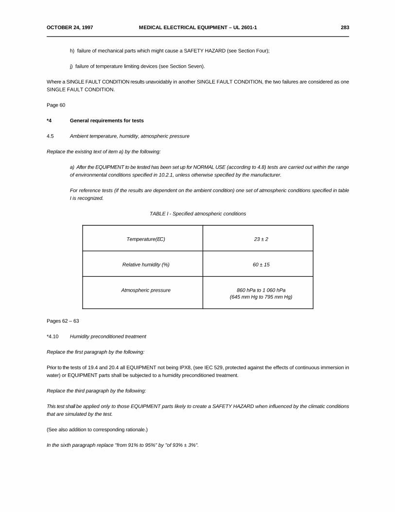
OCTOBER 24, 1997 MEDICAL ELECTRICAL EQUIPMENT – UL 2601-1 283
h) failure of mechanical parts which might cause a SAFETY HAZARD (see Section Four);
j) failure of temperature limiting devices (see Section Seven).
Where a SINGLE FAULT CONDITION results unavoidably in another SINGLE FAULT CONDITION, the two failures are considered as oneSINGLE FAULT CONDITION.
Page 60
*4 General requirements for tests
4.5 Ambient temperature, humidity, atmospheric pressure
Replace the existing text of item a) by the following:
a) After the EQUIPMENT to be tested has been set up for NORMAL USE (according to 4.8) tests are carried out within the rangeof environmental conditions specified in 10.2.1, unless otherwise specified by the manufacturer.
For reference tests (if the results are dependent on the ambient condition) one set of atmospheric conditions specified in tableI is recognized.
TABLE I - Specified atmospheric conditions
Temperature(EC) 23 ± 2
Relative humidity (%) 60 ± 15
Atmospheric pressure 860 hPa to 1 060 hPa(645 mm Hg to 795 mm Hg)
Pages 62 – 63
*4.10 Humidity preconditioned treatment
Replace the first paragraph by the following:
Prior to the tests of 19.4 and 20.4 all EQUIPMENT not being IPX8, (see IEC 529, protected against the effects of continuous immersion inwater) or EQUIPMENT parts shall be subjected to a humidity preconditioned treatment.
Replace the third paragraph by the following:
This test shall be applied only to those EQUIPMENT parts likely to create a SAFETY HAZARD when influenced by the climatic conditionsthat are simulated by the test.
(See also addition to corresponding rationale.)
In the sixth paragraph replace "from 91% to 95%" by "of 93% ± 3%".

284 MEDICAL ELECTRICAL EQUIPMENT – UL 2601-1 OCTOBER 24, 1997
At the end, replace the two dashes by:
– 2 days (48 h) for EQUIPMENT RATED IPX0 (non-protected):
– 7 days (168 h) for EQUIPMENT rated IPX1 to IPX8.
Page 63
*5 Classification
Replace "EQUIPMENT shall be classified..." by "EQUIPMENT and its APPLIED PARTS shall be classified...".
Replaces 5.2 by the following:
5.2 According to the degree of protection against electric shock:
– TYPE B APPLIED PART;
– TYPE BF APPLIED PART;
– TYPE CF APPLIED PART.
Replace 5.3 by the following:
5.3 According to the degree of protection against ingress of water as detailed in the current edition of IEC 529 (see 6.1 l)).
Page 64
6 Identification, marking and documents
6.1 Marking on the outside of EQUIPMENT or EQUIPMENT parts
Page 66 (see also page 256 of amendment 1)
6.1 l) Classification
Second dash, first pair of brackets, replace:
"(1, 4 or 7)" by "(1 to 8)".
Second dash, delete the second pair of brackets and its contents, and also in Appendix D, table D1, delete symbols 11, 12 and 13.
Replace third dash by the following:
– A symbol indicating the type of APPLIED PART according to the degree of protection against electric shock for TYPE B, TYPEBF and TYPE CF APPLIED PARTS (see Appendix D, table DII, symbols 1, 2 and 3).
For clear differentiation with symbol 2, symbol 1 shall not be applied in such a way as to give the impression of being inscribedwithin a square.

OCTOBER 24, 1997 MEDICAL ELECTRICAL EQUIPMENT – UL 2601-1 285
If the EQUIPMENT has more than one APPLIED PART with different degrees of protection, the relevant symbols shall be clearlymarked on such APPLIED PARTS, or on or near relevant outlets (connection points).
DEFIBRILLATION-PROOF APPLIED PARTS shall be marked with the relevant symbols (see Appendix D, table DII, symbols 9,10 and 11).
Add a fourth dash as follows:
– If the protection against the effect of the discharge of a cardiac defibrillator is partly in the PATIENT cable, the symbol 14 inAppendix D, table DI, shall be marked near the relevant outlet.
Page 67
6.1 n) Fuses
Add an asterisk in front of the subclause number.
6.1 v) Protective packing
Add a third paragraph as follows:
The packaging of EQUIPMENT or ACCESSORIES supplied sterile shall be marked as sterile.
Page 68
6.2 Marking on the inside of EQUIPMENT or EQUIPMENT parts
a) First paragraph, last line, replace:
"...Subclause 6.1 z)" by "...Subclause 6.1".
d) Add a new paragraph as follows:
For batteries not intended to be changed by the OPERATOR and which can be changed only with the use of a TOOL, an identifyingmarking referring to information stated in the ACCOMPANYING DOCUMENTS is sufficient.
Add an asterisk in front of item e).
Page 69
6.3 Marking of controls and instruments
Last line, add after "...is checked by inspection", the wording: "and application of the durability test of 6.1".
f) Replace by the following:
f) The functions of OPERATOR controls and indicators shall be identified.
286 MEDICAL ELECTRICAL EQUIPMENT – UL 2601-1 OCTOBER 24, 1997
Add a new item g) as follows:
g) Numeric indications of parameters shall be in SI units according to ISO 1000 with the following additions:
Units outside the International System, which can be used on EQUIPMENT:
– Plane angle units:! revolution,! grade,! degree,! minute of angle,! second of angle;
– Time units:! minute,! hour,! day;
– Energy unit:! electronvolt;
– Pressure of blood and other body fluids:! millimeter of mercury.
*6.3.9 g) to become effective February 6, 2004*
*6.4 Symbols
Last line, replace by:
Compliance is checked by inspection and application of the durability test of 6.1.
Page 71
6.8 ACCOMPANYING DOCUMENTS
6.8.2 Instructions for use
*a) General Information
Add two new dashes, to rank first and third respectively, as follows:
– Instructions for use shall state the function and intended application of the EQUIPMENT.
– Instructions for use shall provide the USER or OPERATOR with information regarding potential electromagnetic or otherinterference between the EQUIPMENT and other devices together with advice regarding avoidance of such interference.
OCTOBER 24, 1997 MEDICAL ELECTRICAL EQUIPMENT – UL 2601-1 287
e) Mains operated EQUIPMENT with additional power source
Last line but one, replace by:
"...external protective conductor in the installation or its arrangement is in doubt, EQUIPMENT shall be...".
f) Removal of primary batteries
Add at the end of the sentence:
"..., unless there is no risk of a SAFETY HAZARD arising".
Add a new item j) as follows:j) Environmental protection
Instructions for use shall:
– identify any risks associated with the disposal of waste products, residues, etc. and the EQUIPMENT and ACCESSORIES atthe end of their useful lives;
– provide advice of minimizing these risks.
Page 73
6.8.3 Technical description
*a) General
Replace the first paragraph by the following:
The technical description shall provide all data, which is essential for safe operation. This shall include:
- data mentioned in subclause 6.1;
- all characteristics of the EQUIPMENT, including range(s), accuracy, and precision of the displayed values or an indication wherethey can be found.
Add an asterisk to subclause number and see corresponding new rationale.
e) Replace the title by:
Environmental conditions for transport and storage
Delete first line to make paragraph begin with:
"The technical description...".
288 MEDICAL ELECTRICAL EQUIPMENT – UL 2601-1 OCTOBER 24, 1997
SECTION TWO
Page 74
*8 Basic safety categories
At the end of the text replace:
"A.1.2" by "A.1.1".
10 Environmental conditions
10.1 Transport and storage
Replace the existing text by the following:
EQUIPMENT shall be capable, while packed for transport and storage, of being exposed to environmental conditions as stated by themanufacturer (see 6.8.3 d)).
10.2 Operation
*10.2.1 Replace the title by: Environment (see also 4.5).
At the end of 10.2 (see also page 257 of Amendment 1), change the compliance paragraph to read:
Compliance with the conditions of 10.2 is checked by application of test tests of this Standard.
SECTION THREE
Page 76
14 Requirements related to classification
14.5 INTERNALLY POWERED EQUIPMENT
a) Replace by the following:
a) Not used.
b) Replace by the following:
*b) INTERNALLY POWERED EQUIPMENT having a means of connection to a SUPPLY MAINS shall comply with therequirements for CLASS I or CLASS II EQUIPMENT while so connected, and with the requirements for INTERNALLY POWEREDEQUIPMENT while not so connected.

OCTOBER 24, 1997 MEDICAL ELECTRICAL EQUIPMENT – UL 2601-1 289
Page 77
14.6 TYPES B, BF and CF EQUIPMENT
Replace 14.6 by the following:
*14.6 TYPES B, BF and CF APPLIED PARTS
a) Not used.
b) Not used.
c) APPLIED PARTS which are specified in the ACCOMPANYING DOCUMENTS as suitable for DIRECT CARDIACAPPLICATION shall be TYPE CF.
d) Not used.
Page 82
17 Separation
a) Compliance section, fourth paragraph which begins "if inspection of the APPLIED PART", last two lines to read:
...insulation between LIVE parts and the APPLIED PART (item 17 a) 1) above), between LIVE parts and the metal part (item 17a) 2) above) or between LIVE parts and the intermediate circuit (item 17 a) 3) above).
Page 83g) Compliance section, change fourth paragraph to read:
If inspection of the PROTECTIVELY EARTHED metal part in item 17 g) 2) or of the intermediate circuit in item 17 g) 3) gives riseto doubt concerning the effectiveness of the separation under SINGLE FAULT CONDITION the ENCLOSURE LEAKAGECURRENT shall be measured by short-circuiting the insulation between LIVE parts and the metal part (item 17 g) 2) above) orbetween LIVE parts and the intermediate circuit (item 17 g) 3) above).
Add a new item h) as follows:
*h) Arrangements used to isolate DEFIBRILLATION-PROOF APPLIED PARTS from other parts shall be so designed that:
– during a discharge of a cardiac defibrillator to a PATIENT connected to a DEFIBRILLATION-PROOF APPLIED PART,hazardous electrical energies do not appear on:
! the ENCLOSURE, including the outer surfaces of accessible leads and connectors,
! any SIGNAL INPUT PART,
! any SIGNAL OUTPUT PART
290 MEDICAL ELECTRICAL EQUIPMENT – UL 2601-1 OCTOBER 24, 1997
! metal foil for test on which the EQUIPMENT is placed and which has an area at least equal to the base of the EQUIPMENT.
– after exposure to the defibrillation voltage, the EQUIPMENT, after any necessary time of recovery stated in theACCOMPANYING DOCUMENTS, shall continue to perform its intended function as described in the ACCOMPANYINGDOCUMENTS.
Compliance is checked by the following impulse voltage tests:
– (Common-mode test) The EQUIPMENT is connected to the test circuit shown in figure 50. The test voltage is applied to allthe PATIENT CONNECTIONS connected together and isolated from earth;
– (Differential-mode test) The EQUIPMENT is connected to the test circuit shown in figure 51. The test voltage is applied to eachPATIENT CONNECTION in turn with all the remaining PATIENT CONNECTIONS being connected to earth.
NOTE - The differential-mode test is not used when the APPLIED PART consists of a single PATIENT CONNECTION.
During each test:
– the PROTECTIVE EARTH CONDUCTOR of CLASS I EQUIPMENT is connected to earth. CLASS I EQUIPMENT which iscapable of operation without a SUPPLY MAINS, e.g. having an internal battery, is tested again without the protective earthconnection;
– the EQUIPMENT shall not be energized;
– insulating surfaces of APPLIED PARTS are covered with metal foil or immersed in a saline solution as specified in 19.4 h) 9);
– any connection to a FUNCTIONAL EARTH TERMINAL is removed; where a part is internally connected to earth for functionalpurposes, either such a connection shall be considered a protective earth connection and shall comply with the requirements ofclause 18, or it shall be removed for the purpose of the present text;
– parts specified in the first dash of this subclause that are not PROTECTIVELY EARTHED are connected to an oscilloscope.
After the operation of S, the peak voltage between the points Y1 and Y2 shall not exceed 1 V.
Each test is repeated with V reversed.T
After any necessary time of recovery, stated in the ACCOMPANYING DOCUMENTS, the EQUIPMENT shall continue to perform itsintended functions as described in the ACCOMPANYING DOCUMENTS.
OCTOBER 24, 1997 MEDICAL ELECTRICAL EQUIPMENT – UL 2601-1 291
Page 84 and 85
18 Protective earthing, functional earthing and potential equalization.
b) First and second lines, change:
"PROTECTIVE EARTH CONDUCTOR of the power system" to "protective conductor in the installation".
f) Second paragraph, change:
"protective contact" to "protective earth contact".
Third paragraph, change:
"protective contact" to "protective earth pin".
Compliance section, first paragraph, replace the following phrase:
"A current not less than 10 A and not exceeding 25 A from current source with a frequency of 50 Hz or 60 Hz with a no-loadvoltage not exceeding 6 V is passed for at least 5 s..." by
"A current of 25 A or 1.5 times the rated current of the EQUIPMENT, whichever is greater (± 10%), from the current source witha frequency of 50 Hz or 60 Hz with a no-load voltage not exceeding 6 V is passed for 5 s to 10 s...".
g) Add an asterisk in front of item g).
Page 85
19 Continuous LEAKAGE CURRENTS and PATIENT AUXILIARY CURRENTS
19.1 General requirements
e) At the beginning of the three dashes, change:
"EQUIPMENT" to "APPLIED PARTS".
In the text of all three dashes "CONNECTION" should also be printed in small capitals.
Add a new item g) as follows:
g) EQUIPMENT with multiple PATIENT CONNECTIONS shall be investigated to ensure that, under NORMAL CONDITIONS,the PATIENT LEAKAGE CURRENT and the PATIENT AUXILIARY CURRENT do not exceed the allowable values while one ormore PATIENT CONNECTIONS are:
– disconnected from the PATIENT; and
– disconnected from the PATIENT and earthed.
292 MEDICAL ELECTRICAL EQUIPMENT – UL 2601-1 OCTOBER 24, 1997
Testing shall be carried out if an examination of the EQUIPMENT circuit indicates that the PATIENT LEAKAGE CURRENT ofthe PATIENT AUXILIARY CURRENT may increase to excessive levels under the above conditions, and actual measurementsshould be limited to a representative number of combinations.
Page 86 – 87 (see also page 259 of Amendment 1)
19.2 SINGLE FAULT CONDITIONSb) First dash, second line, delete:
", not PROTECTIVELY EARTHED"
b) First dash, first bullet, replace paragraph by the following:
! The SIGNAL INPUT PART(S)or SIGNAL OUTPUT PART(S) are designated by the manufacturer for connectionto EQUIPMENT in situations where a risk of external voltage does not exist (see IEC 601-1-1).
b) First dash, replace the second and the third bullets by the following:
! for TYPE B APPLIED PARTS, unless inspection of the circuits and physical arrangement shows that a SAFETYHAZARD exists:
! for F-TYPE APPLIED PARTS.
b) Third dash, replace the two bullets by the following:
! for TYPE B APPLIED PARTS, unless inspection of the circuits and physical arrangements shows that a SAFETYHAZARD exists:
! for F-TYPE APPLIED PARTS.
c) First paragraph, delete, "not PROTECTIVELY EARTHED". Replace the second paragraph with the following:This requirement is only applied where the SIGNAL INPUT PART(S) or SIGNAL OUTPUT PART(S) are designated by the manufacturerfor connection to EQUIPMENT in situations where a risk of external voltage exists (see IEC 601-1-1).
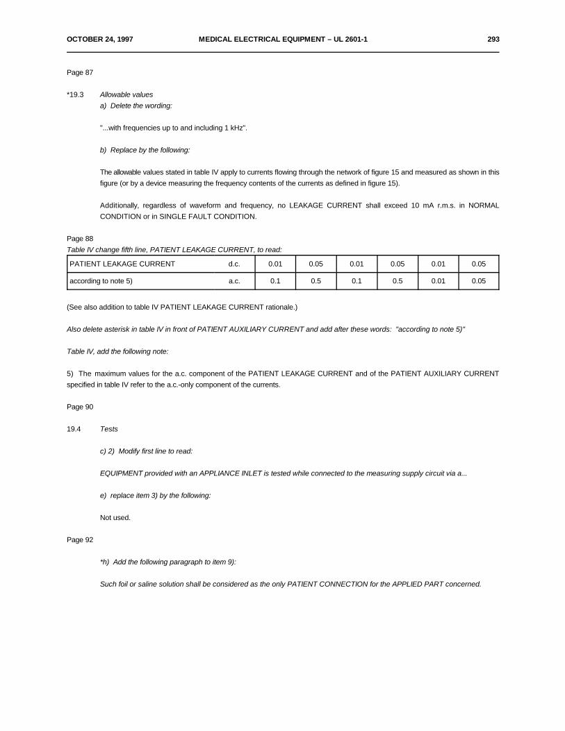
OCTOBER 24, 1997 MEDICAL ELECTRICAL EQUIPMENT – UL 2601-1 293
Page 87
*19.3 Allowable valuesa) Delete the wording:
"...with frequencies up to and including 1 kHz".
b) Replace by the following:
The allowable values stated in table IV apply to currents flowing through the network of figure 15 and measured as shown in thisfigure (or by a device measuring the frequency contents of the currents as defined in figure 15).
Additionally, regardless of waveform and frequency, no LEAKAGE CURRENT shall exceed 10 mA r.m.s. in NORMALCONDITION or in SINGLE FAULT CONDITION.
Page 88Table IV change fifth line, PATIENT LEAKAGE CURRENT, to read:
PATIENT LEAKAGE CURRENT d.c. 0.01 0.05 0.01 0.05 0.01 0.05
according to note 5) a.c. 0.1 0.5 0.1 0.5 0.01 0.05
(See also addition to table IV PATIENT LEAKAGE CURRENT rationale.)
Also delete asterisk in table IV in front of PATIENT AUXILIARY CURRENT and add after these words: "according to note 5)"
Table IV, add the following note:
5) The maximum values for the a.c. component of the PATIENT LEAKAGE CURRENT and of the PATIENT AUXILIARY CURRENTspecified in table IV refer to the a.c.-only component of the currents.
Page 90
19.4 Tests
c) 2) Modify first line to read:
EQUIPMENT provided with an APPLIANCE INLET is tested while connected to the measuring supply circuit via a...
e) replace item 3) by the following:
Not used.
Page 92
*h) Add the following paragraph to item 9):
Such foil or saline solution shall be considered as the only PATIENT CONNECTION for the APPLIED PART concerned.
294 MEDICAL ELECTRICAL EQUIPMENT – UL 2601-1 OCTOBER 24, 1997
Page 95
20 Dielectric strength
20.1 General requirements for all types of EQUIPMENT
Item A-f Add an asterisk in front of this item and replace the second line, by the following:
This insulation shall be equivalent to BASIC INSULATION.
Page 96
Item A-k c) Replace by the following:
The parts in question are effectively separated by a PROTECTIVELY EARTHED shielding or by a PROTECTIVELY EARTHED intermediatecircuit.
Item A-k d) Replace the text by the following:
The SIGNAL INPUT or SIGNAL OUTPUT PARTS are designated by the manufacturer for connection to EQUIPMENT in situations whereno risk of external voltage exists (see IEC 601-1-1).
Page 97
*20.3 Values of test voltages
Combine last two existing paragraphs, page 98, into just one.
Immediately before table V, add the following paragraph:
For DEFIBRILLATION-PROOF APPLIED PARTS, the reference voltage (U) is determined without regard to the possible presence ofdefibrillation voltages (see also subclause 17 *h)).
Under table V, replace existing note by:
NOTES
1 Tables VI and VII, not used.
2 Where the voltage to which the relevant insulation is subjected in NORMAL USE is non-sinusoidal a.c., the test may beperformed using a sinusoidal 50 Hz test voltage. In this case the value of the test voltage shall be determined from table V usinga reference voltage (U) equal to the measured peak-to-peak voltage divided by 2/2.
SECTION FOUR
Page 100
21 Mechanical strength
In subclause *21.6 print table VIII in italics.
Page 106
*26 Vibration and noise
OCTOBER 24, 1997 MEDICAL ELECTRICAL EQUIPMENT – UL 2601-1 295
Instead of "Not used" read "No general requirement".
27 Pneumatic and hydraulic power
Instead of "Under consideration" read "No general requirement".
Page 107
28 Suspended masses
*28.5 Dynamic loads
Instead of "Not used" read "No general requirement".
Page 107
29 X-Radiation
29.1 Instead of "Not used" read:
– For diagnostic X-ray equipment - See Collateral Standard IEC 601-1-3 (see Appendix L);
– For radiotherapy equipment - No general requirement, see relevant Particular Standard.
Clauses 30 to 35
Keep titles and change text from "Under consideration" to "No general requirement".
*36 Electromagnetic compatibility
Replace "Under consideration" with: See IEC 601-1-2 (see Appendix L).
SECTION SIX
Page 112
40 Requirements and tests for CATEGORY AF EQUIPMENT, parts and components thereof
*40.3 Low-energy circuits
First dash, second line, change: "or ether" to: "of ether".
Last paragraph (compliance), instead of:
"...determination of U max, I max, L max and C max..." read:
"...determination of U max, I max, R, L max and C max...".
296 MEDICAL ELECTRICAL EQUIPMENT – UL 2601-1 OCTOBER 24, 1997
Page 115
41 Requirements and tests for CATEGORY APG EQUIPMENT, parts and components thereof
41.1 General
Compliance paragraph, third line, change "...terminal..." to "...thermal...".
SECTION SEVEN
Page 121
42.3 1) d)
Texts of items e) and f) being parts of item d) above, replace the headings "e)" and "f)" by bullets.
Page 123 and 124
43 Fire prevention
Add the following title before the first paragraph:
43.1 Strength and rigidity
Add the following subclause:
*43.2 Oxygen enriched atmospheres
No general requirement.
44 Modify title to read:
44 Overflow, spillage, leakage, humidity, ingress of liquids, cleaning, sterilization, disinfection and compatibility
44.3 Spillage
After "Compliance is checked by the following test", replace the two following paragraphs:
The EQUIPMENT is placed according to subclause 4.6 a). A quantity of 200 ml of normal tap water is poured steadily on an arbitrary pointon the top surface of the EQUIPMENT, for approximately 15 s, from a height not exceeding 5 cm.
After the test, the EQUIPMENT shall comply with all the requirements of this Standard for NORMAL CONDITION.
*44.4 Leakage (see also page 262 of Amendment 1)
Add at end of requirement after "...a SAFETY HAZARD":
(see also subclause *52.4.1).
OCTOBER 24, 1997 MEDICAL ELECTRICAL EQUIPMENT – UL 2601-1 297
Page 125
44.6 Ingress of liquids
Change compliance section to read:
Compliance is checked by the tests of IEC 529.
EQUIPMENT shall withstand the dielectric strength test specified in clause 20. Inspection shall show that water which may have enteredEQUIPMENT can have no harmful effect; in particular, there shall be no trace of water on insulation for which CREEPAGE DISTANCESare specified in subclause 57.10.
Add a new subclause as follows:
*44.8 Compatibility with substances used with the EQUIPMENT
No general requirement.
Page 127 and 128
*48 Materials in APPLIED PARTS in contact with the body of the PATIENT
Delete asterisk and replace title by "Biocompatibility".
Replace "Not used" by the following:
Parts of EQUIPMENT and ACCESSORIES intended to come into contact with biological tissues, cells or body fluids, shall be assessed anddocumented according to the guidance and principles given in ISO 10993-1.
Compliance is checked by inspection of the information provided by the manufacturer.
49 Interruption of the power supply
Add an asterisk in front of the clause number.
SECTION EIGHT
Page 128 and 129
51 Protection against hazardous output
51.1 Intentional exceeding of safety limits
Add an asterisk in front of subclause number and replace existing text (which has been added to the rationale, Appendix A, clause A.2), with:
No general requirement.
298 MEDICAL ELECTRICAL EQUIPMENT – UL 2601-1 OCTOBER 24, 1997
51.2 Indication of parameters relevant to safety
Add an asterisk in front of subclause number and replace existing text (which has been added to the rationale, Appendix A, clause A.2), with:
No general requirement.
Add a new subclause as follows:
*51.5 Incorrect output
No general requirement.
SECTION NINE
52 Abnormal operation and fault conditions
52.1 Add to first paragraph the following:
Additionally the safety of EQUIPMENT incorporating programmable electronic systems is checked by applying the rules of the future IECCollateral Standard 601-1-4 (see Appendix L).
Page 129
*52.4.1 First dash, replace the phrase:
"...poisonous or ignitable gas..." with "...poisonous or ignitable substance...".
Page 132
52.5.8 Additional tests for motor operated EQUIPMENT
Just before the sentence introducing table XII, reinstate the sentence mistakenly deleted in Amendment 1:
Temperatures are measured as specified in subclause 42.3.4).
Page 133
52.5.9 Failure of components
Add a new third paragraph as follows:
Capacitors (X1 and X2) complying with IEC 384-14, which are connected between parts of opposite polarity of the mains part, are exemptedfrom this requirement. Thus, failure of such capacitors shall not be simulated.
NOTE - For information concerning X1 and X2, see IEC 384-14, subclause 1.5.3.
OCTOBER 24, 1997 MEDICAL ELECTRICAL EQUIPMENT – UL 2601-1 299
SECTION TEN
Page 138
56 Components and general assembly
56.3 Connections - General
Add the following new item with an asterisk in front:
*c) Any connector in a lead having a CONDUCTIVE CONNECTION to a PATIENT shall be constructed in such a manner that noCONDUCTIVE CONNECTION of that part of the said connector which is remote from the PATIENT can contact earth or possible hazardousvoltages.
Compliance is checked by inspection and by applying to the conductive connection of that part of the connector identified above those ofthe following tests which are applicable:
– the said part shall not come into contact with a flat conductive surface of not less than 100 mm diameter;
– for single-pole connectors, the straight unjointed test finger with the same dimensions as the standard test finger of figure 7shall not make electrical contact with the said part if applied in the least favorable position against the access openings with a forceof 10 N ± 2 N;
– if able to be plugged into a mains socket, the said part shall be protected from making contact with parts of mains voltage byinsulating means providing a CREEPAGE DISTANCE of at least 1.0 mm and a dielectric strength of 1500 V.
*56.4 Connections of capacitors
Third dash, first line, replace "ENCLOSURE" with "enclosure".
Page 139 and 140
56.6 Temperature and overload control devices
b) First dash, delete the wording:
"...the temperature range shall not exceed substantially that which is necessary for the proper functioning of EQUIPMENT and...".
56.7 Batteries
Add a new item c) with an asterisk in front as follows:
*c) Battery state
No general requirement.
300 MEDICAL ELECTRICAL EQUIPMENT – UL 2601-1 OCTOBER 24, 1997
56.8 Indicators
Change first three lines to read:
Unless indication is otherwise apparent to the OPERATOR from the normal operating position, indicator lights shall be provided.
– to indicate that EQUIPMENT is energized (see subclause 6.3 a)).
Page 142 and 143
56.11 Cord-connected hand-held and foot-operated control devices
d) Entry of liquids
First dash, replace "drip-proof" with "at least IPX1 according to IEC 529".
Replace compliance sentence with:
Compliance is checked by the tests of IEC 529.
Second dash, end of second line, replace "of watertight construction" with: "IPX8 according to IEC 529".
Replace compliance sentence with:
Compliance is checked by the tests of IEC 529.
e) Connection cords
Third line, replace "flexible supply cords" with "POWER SUPPLY CORDS".
57 MAIN PARTS, components and layout
57.2 MAINS CONNECTORS, APPLIANCE INLETS and the like
Modify item b) to read:
*b) Construction
No general requirement.
Add a new item as follows:
*g) Except where a functional earth needs to be provided, CLASS I APPLIANCE INLETS shall not be used in CLASS IIEQUIPMENT.

OCTOBER 24, 1997 MEDICAL ELECTRICAL EQUIPMENT – UL 2601-1 301
Page 144
57.4 Connection of POWER SUPPLY CORDS
a) Cord anchorages
Replace third and fourth paragraph of the replacement text (see Amendment 1, page 266 for the last five paragraphs) by thefollowing:
For the measurement of the longitudinal displacement, while the cord is subjected to the pull, a mark is made on the cord at adistance of approximately 2 cm from the cord anchorage or other suitable point, before starting the tests.
After the tests, the displacement on the cord sheath in relation to the cord anchorage or the above other suitable point while thecord is subjected to the pull, is measured.
Page 146
b) Cord guards
Fourth line, replace:
"supply cord" by "POWER SUPPLY CORD".
Replace the last three paragraphs by the following:
Guards which fail the above dimensional tests shall have to pass the test described in IEC 335-1, Amendment 6, 1988, subclause25.10.
Page 147
57.5 MAINS TERMINAL DEVICES and wiring of MAINS PART
*a) General requirements for MAINS TERMINAL DEVICES
First paragraph, change last line into:
"means of screws, nuts, soldering, clamping, crimping of conductors or equally effective methods."
b) Arrangement of MAINS TERMINAL DEVICES
Second line, replace:
"flexible supply cords" by "POWER SUPPLY CORDS".
302 MEDICAL ELECTRICAL EQUIPMENT – UL 2601-1 OCTOBER 24, 1997
Page 148 and 149
57.6 Mains fuses and OVER-CURRENT RELEASES
Delete "for" in second line before "CLASS II"
57.8 Wiring of the MAINS PART
a) Insulation
Replace text by:
The insulation of an individual conductor in the MAINS PART shall be at least electrically equivalent to that of the individualconductors of POWER SUPPLY CORDS complying with IEC 227 or 245, or that conductor shall be considered to be a bareconductor.
Compliance is checked by the following test:
The insulation is regarded to be electrically equivalent, if it withstands a dielectric strength test of 2 000 V for 1 min. The testvoltage is applied to a sample of the wire between the conductor and aluminum foil wrapped around the insulation for a length of10 cm.
b) Cross-section
Second dash, print second paragraph:
"If any doubt...in the MAINS PART" in italics.
Page 149 and 150
*57.9 Mains supply transformers
57.9.1 Overheating
a) Short circuit
Modify first sentence of the first dash to read as follows:
– Mains supply transformers, provided with a protective device for limitation of the winding temperatures, areconnected to a supply voltage which is the least favorable within the limits of 90% of the lowest to 110% of the highestRATED supply voltage or the RATED supply voltage range.
(In the same subclause, add dashes in front of the last three paragraphs.)
b) Overload
Subclause, including table XX, is to be entirely printed in italics.
OCTOBER 24, 1997 MEDICAL ELECTRICAL EQUIPMENT – UL 2601-1 303
Replace, fourth dash, fifth bullet, by the following:
Mains supply transformers having OVER-CURRENT RELEASES as protective devices are loaded so that the test current in thecircuit is as high as possible according to the trip current stated by the manufacturer of the OVER-CURRENT RELEASES butdoes not cause the releases to operate, the test being continued until a steady thermal condition is obtained. The OVER-CURRENT RELEASES shall be replaced by links of negligible impedance.
Page 154
57.9.4 Construction
f) At the end of the first paragraph, replace "Table XX" by "Table XVI".
Page 154
57.10 CREEPAGE DISTANCES and AIR CLEARANCES
Add an asterisk in front of subclause number; additionally delete the asterisks in front of items *a) to *d).
a) Values
Add a fourth dash as follows:– Between DEFIBRILLATION-PROOF APPLIED PARTS and other parts, CREEPAGE DISTANCES and AIRCLEARANCES shall be not less than 4 mm.
b) Application
Third dash, replace:
"ENCLOSURES" by "enclosures".
d) Measurement of CREEPAGE DISTANCES and AIR CLEARANCES
Replace the fifth paragraph by the following:CREEPAGE DISTANCES and AIR CLEARANCES through slots or openings in external parts shall be measured to the standardtest finger of figure 7.
Page 156
In table XVI, first column, first line (corresponding to A-F), instead of "BASIC INSULATION..." read "Equivalent to BASIC INSULATION..."
In table XVI, eighth column, second row, instead of: "380" read "400".

304 MEDICAL ELECTRICAL EQUIPMENT – UL 2601-1 OCTOBER 24, 1997
Page 157
59 Construction and layout
59.1 Internal wiring
a) Mechanical protection
Second line, replace:
"at edges or sharp corners" with "at sharp corners and edges".
c) Insulation
Third dash, change: "75EC" to "70EC".
Compliance section, add a new paragraph as follows:
Compliance of the sheath mentioned in the second dash is checked as follows:
The insulation shall withstand a dielectric strength test of 2000 V for 1 min. The test voltage is applied between a metal rodinserted into a sample of the sheath and metal foil wrapped around the insulation for a length of 10 cm.
Page 160
59.3 Excessive current and voltage protection
Second dash, replace: "Test under consideration" by:
Compliance is checked by inspection for the presence of protective means and if necessary by inspection of the design data.
Page 160
59.4 Oil containers
Replace compliance sentence by the following:
Compliance is checked by inspection of EQUIPMENT and technical description, and by manual test.
Figures
Page 162
Figure 2
In legend, No. 12, replace:
"protectively earthed" by "PROTECTIVELY EARTHED".
OCTOBER 24, 1997 MEDICAL ELECTRICAL EQUIPMENT – UL 2601-1 305
Page 167
Figure 11
At the end of title, replace:
"to earth" by "to earth potential".
Page 174
Figure 18
At top of figure, replace "S " by "S " (keep the other S lower down in figure).5 9 5
Page 197
Legends to figures 39 to 47
Add the following item:
7) In figures 43 to 45 uncemented joints are mentioned for conditions of examples 5 to 7. For a description of cemented joints see subclause57.9.4.f), second dash, in this Standard.
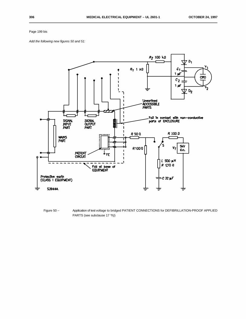
306 MEDICAL ELECTRICAL EQUIPMENT – UL 2601-1 OCTOBER 24, 1997
Page 199 bis
Add the following new figures 50 and 51:
Figure 50 – Application of test voltage to bridged PATIENT CONNECTIONS for DEFIBRILLATION-PROOF APPLIEDPARTS (see subclause 17 *h))
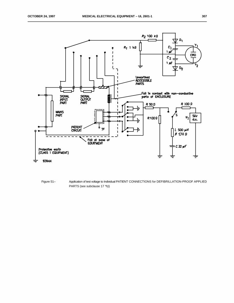
OCTOBER 24, 1997 MEDICAL ELECTRICAL EQUIPMENT – UL 2601-1 307
Figure 51– Application of test voltage to Individual PATIENT CONNECTIONS for DEFIBRILLATION-PROOF APPLIEDPARTS (see subclause 17 *h))
308 MEDICAL ELECTRICAL EQUIPMENT – UL 2601-1 OCTOBER 24, 1997
Appendix A
General guidance and rationale
Page 200 – 203
A1 General guidance
A1.2 Guidance to the second edition
Third paragraph from top of page 202, replace:
"TYPE CF EQUIPMENT" by "EQUIPMENT with a TYPE CF APPLIED PART".
A1.3 Protection against electric shock hazards
Replace third paragraph from top of page 203 by the following:
The sensitivity of the human or animal body to electric currents, depending upon the degree and nature of contact with the EQUIPMENT, leadsto a system of classification reflecting the degree and quality of protection provided by the APPLIED PARTS (classified as TYPES B, BF andCF APPLIED PARTS). TYPES B AND BF APPLIED PARTS are generally suitable for applications involving external or internal contact withthe PATIENT, excluding the heart. TYPE CF APPLIED PARTS are suitable for DIRECT CARDIAC APPLICATIONS.
Page 206
A1.7 Protection against excessive temperatures and other safety hazards
In the above title, change "safety hazards" into "SAFETY HAZARDS".
Last three dashes, in titles, change:
"(Clause 43)", "(Clause 45)", "(Clause 49)" respectively to:
"(see clause 43)", "(see clause 45)", and "(see clause 49)".
Second dash, first line, change:
"the fire hazard" to "prevention of the fire hazard".
Page 207
Add the following new subclause:
A1.10 APPLIED PARTS AND ENCLOSURES - General
Parts which are intended to contact PATIENTS can present greater hazards than other parts of the ENCLOSURE, and these APPLIEDPARTS are therefore subject to more stringent requirements, for example, for temperature limits and (according to classification B/BF/CF)for LEAKAGE CURRENT.
OCTOBER 24, 1997 MEDICAL ELECTRICAL EQUIPMENT – UL 2601-1 309
NOTE - Other ACCESSIBLE PARTS of the ENCLOSURES of MEDICAL ELECTRICAL EQUIPMENT are subject to tests whichare more demanding than those for enclosures of other kinds of equipment, because the PATIENT may touch them, or theOPERATOR may touch them and the PATIENT simultaneously.
In order to determine which requirements apply, it is necessary to distinguish between APPLIED PARTS and parts which are simplyconsidered as the ENCLOSURE. However there can be difficulties in doing this, especially with parts which can be expected to contact thePATIENT on some occasions but do not have to do so for the EQUIPMENT to perform its function.
The distinction between ENCLOSURES and APPLIED PARTS is made according to two criteria. Firstly, if contact is essential for theNORMAL USE of the EQUIPMENT, the part is subject to the requirements for APPLIED PARTS.
If contact is incidental to the functioning of the EQUIPMENT, the part is categorized according to whether contact results from deliberateaction by the PATIENT or by the OPERATOR. Where contact is incidental and results from action by the PATIENT, the PATIENT is in mostrespects no more at risk than any other person, so the requirements for ENCLOSURES are sufficient.
In order to assess which parts are APPLIED PARTS, PATIENT CONNECTIONS and PATIENT CIRCUITS, the following process isemployed in the order shown:
a) Determine whether the EQUIPMENT has an APPLIED PART and if it has, identify the extent of the APPLIED PART (thesedecisions being based on non-electrical considerations).
b) If there is no APPLIED PART, there are no PATIENT CONNECTION(S) or PATIENT CIRCUITS(S).
c) If there is an APPLIED PART, there may be one or more PATIENT CONNECTION(S). Where a conductive part of theAPPLIED PART is not in direct contact with the PATIENT, but is not isolated and current can flow through such a part to or fromthe PATIENT, it is to be treated as an individual PATIENT CONNECTION.
d) The PATIENT CIRCUIT then consists of these PATIENT CONNECTION(S) and any other conductive parts from which theyare inadequately insulated/segregated.
NOTE - Relevant separation requirements are those which relate to APPLIED PARTS and are necessary to comply with thedielectric strength tests in clause 20, and the CREEPAGE DISTANCE and AIR CLEARANCE requirements in subclause 57.10.
Page 207
A.2 Rationale to particular clauses and subclauses
Add the following new subclauses:
Subclause 2.1.5
This General Standard includes a definition for APPLIED PART which, in most cases, clearly establishes which parts of the EQUIPMENTneed to be treated as APPLIED PARTS and comply with more stringent requirements than those for ENCLOSURES.
310 MEDICAL ELECTRICAL EQUIPMENT – UL 2601-1 OCTOBER 24, 1997
Excluded are those parts which are only likely to be contacted following an unnecessary action by the PATIENT. Thus:
– An infrared therapy lamp does not have an APPLIED PART because it does not need to be brought into direct contact with thePATIENT.
– The only part of an X-ray table which is an APPLIED PART is the top on which the PATIENT lies.
– Likewise, in an MRI scanner, the only APPLIED PARTS are the table supporting the PATIENT and any other parts which mustbe brought into direct contact with the PATIENT.
This definition may not always clearly establish whether an individual part of a particular item of EQUIPMENT is an APPLIED PART. Suchcases need to be considered on the basis of the above rationale, or by reference to the Particular Standards which should specifically identifythe APPLIED PART(S) in particular types of EQUIPMENT.
Subclause 2.1.15
Where APPLIED PARTS have PATIENT CONNECTIONS, these should be adequately separated from specified LIVE parts within theEQUIPMENT and, in the case of TYPE BF and TYPE CF APPLIED PARTS, from earth. Testing of the dielectric strength of the insulationinvolved, and assessment of CREEPAGE DISTANCE and AIR CLEARANCE are used to verify compliance with these criteria.
The definition of the PATIENT CIRCUIT is intended to identify all the parts of the EQUIPMENT which can readily provide current to, or receiveit from, the PATIENT CONNECTION(S).
For an F-TYPE APPLIED PART, the PATIENT CIRCUIT extends as seen from the PATIENT into the EQUIPMENT to the point(s) wherethe prescribed insulation and/or protection impedance is completed.
For a TYPE B APPLIED PART, the PATIENT CIRCUIT may be connected to protective earth.
Subclause 2.1.23
One of the potential hazards associated with the application of an APPLIED PART is the fact that LEAKAGE CURRENT may flow throughthe PATIENT via the APPLIED PART. Particular limits are placed on the magnitude of these currents, both in the NORMAL CONDITIONand in various fault conditions.
NOTE - The current which flows through the PATIENT, between various parts of the APPLIED PART, is known as PATIENTAUXILIARY CURRENT. The LEAKAGE CURRENT which flows through the PATIENT to earth is known as PATIENT LEAKAGECURRENT.
The definition of PATIENT CONNECTION is intended to ensure the identification of each individual part of the APPLIED PART betweenwhich current may flow as PATIENT AUXILIARY CURRENT, and from which PATIENT LEAKAGE CURRENT may flow into an earthedPATIENT.
In some cases it will be necessary to carry out PATIENT LEAKAGE CURRENT and PATIENT AUXILIARY CURRENT measurements todetermine which parts of the APPLIED PARTS are individual PATIENT CONNECTIONS.
OCTOBER 24, 1997 MEDICAL ELECTRICAL EQUIPMENT – UL 2601-1 311
PATIENT CONNECTIONS are not always accessible to touch. Any conductive parts of the APPLIED PART which come into electricalcontact with the PATIENT, or which are prevented from doing so only by insulation or air gaps which do not comply with the relevant dielectricstrength tests of AIR CLEARANCE and CREEPAGE DISTANCE requirements specified in this standard, are PATIENT CONNECTIONS.
Examples include the following:
– A table top supporting a PATIENT is an APPLIED PART. Sheets do not provide adequate insulation and the conductive partsof the table top would therefore be classified as PATIENT CONNECTIONS
– The administration set or needle of an infusion controller is an APPLIED PART. Conductive parts of the controller separatedfrom the (potentially conducting) fluid column by inadequate insulation would be PATIENT CONNECTIONS.
Where an APPLIED PART has a surface of insulating material, subclause 19.4 h) 9) specifies that it is tested using foil or saline solution.This is then considered as a PATIENT CONNECTION.
Subclause 2.1.24
TYPE B APPLIED PARTS provide the lowest degree of PATIENT protection of all the types of APPLIED PART and are not suitable forDIRECT CARDIAC APPLICATION.
Subclause 2.1.25
TYPE BF APPLIED PARTS provide a degree of PATIENT protection higher than provided by TYPE B APPLIED PARTS. This degree ofprotection is achieved by isolation from earthed parts and other ACCESSIBLE PARTS of the EQUIPMENT, thus limiting the magnitude ofcurrent that would flow through the PATIENT in the event of the PATIENT contacting other LIVE equipment.
However, TYPE BF APPLIED PARTS are not suitable for DIRECT CARDIAC APPLICATION.
Subclause 2.1.26
TYPE CF APPLIED PARTS provide the highest degree of PATIENT protection. This degree of protection is achieved by increased isolationfrom earthed parts and other ACCESSIBLE PARTS of the EQUIPMENT, further limiting the magnitude of possible current flow through thePATIENT. TYPE CF APPLIED PARTS are suitable for DIRECT CARDIAC APPLICATION.
Subclause 2.1.27
A DEFIBRILLATION-PROOF APPLIED PART is protected only against discharges of defibrillators designed in accordance with IEC 601-2-4.Sometimes defibrillators of other construction are used in hospitals, e.g. defibrillators with higher voltages and pulses. Such defibrillators mayalso damage DEFIBRILLATION-PROOF APPLIED PARTS.
312 MEDICAL ELECTRICAL EQUIPMENT – UL 2601-1 OCTOBER 24, 1997
Page 207 and 208 Delete subclauses 2.2.24 and 2.2.26.
Page 208 Add a new subclause as follows:
Subclause 2.6.4
In MEDICAL ELECTRICAL EQUIPMENT functional earth connections may be made by means of a FUNCTIONAL EARTH TERMINALwhich is accessible to the OPERATOR. Alternatively this Standard also allows a functional earth connection for CLASS II EQUIPMENT viaa green and yellow conductor in a POWER SUPPLY CORD. In this case the parts concerned have to be insulated form ACCESSIBLEPARTS (see subclause 18 l)).
Page 210
Subclause 4.1
Last paragraph but one, replace: "leakage current" by "LEAKAGE CURRENT".
Page 210
Subclause 4.10
Paragraph b), change first line into:
b) According to IEC 529, the ENCLOSURE of EQUIPMENT RATED IPX8 prevents....
Add at the end of the following new paragraph:
Parts sensitive to humidity, normally used in controlled environments and which do not influence safety, need not be subjected tothis test. Examples are: high-density storage media in computer-based systems, disc and tape drives, etc.
Page 211 – 212
Add the following new subclause:
Subclause 6.1. n)
For fuses in accordance with IEC 127, the marking of the type and rating should be in accordance thereto. Examples of marking: T 315Lor T 315mAL, F 1.25H or F 1.25AH.
Subclause 6.1 z)
Last paragraph, change:
"C H O (MW60.1)" to C H O (MW60.1)".2 8 3 8
and replace last sentence by:
It has a relative density of 0.785 at 20EC, boiling point 82.5EC at 1013 hPa.
OCTOBER 24, 1997 MEDICAL ELECTRICAL EQUIPMENT – UL 2601-1 313
Add a new subclause as follows:
Subclause 6.2 e)
For fuses in accordance with IEC 127, the marking of the type and rating should be in accordance thereto. Examples of marking: T 315Lor T 315mAL, F 1.25H or F 1.25AH.
Subclause 6.4
No special color is requested.
Subclause 6.8.2 a)
– It is important to ensure that an EQUIPMENT is not used inadvertently in an application for which it is not intended.
– Examples of interference would include:
Power supply transients, magnetic interference, mechanical interaction, vibration, thermal radiation, optical radiation.
Subclause 6.8.3. a)
Accuracy and precision are not possible to define in this General Standard. These concepts have to be addressed in Particular Standards.
Subclause 10.2.1
Add the following paragraph:
The EQUIPMENT should be safe according to this standard when operated under the conditions of subclause 10.2 but it need only be fullyoperable under conditions specified by the manufacturer in the ACCOMPANYING DOCUMENTS (see also definition of NORMAL USE).
Subclause 10.2.2
In the fourth, fifth and sixth paragraphs replace headings a), b) and c) by dashes.
Subclause 10.2.2 a)
Concerns the French text only.
314 MEDICAL ELECTRICAL EQUIPMENT – UL 2601-1 OCTOBER 24, 1997
Page 212
Add new subclauses as follows:
Subclause 14.5 b)
If INTERNALLY POWERED EQUIPMENT has a means of connection to a separate battery charger or power supply unit which in turn hasa means of connection to the SUPPLY MAINS, the battery charger or power supply unit is considered as part of the EQUIPMENT and therequirements apply.
These requirements do not apply to EQUIPMENT (including any separate power supply unit or battery charger) which is incapable of beingconnected to a SUPPLY MAINS and to a PATIENT simultaneously.
Subclause 14.6
EQUIPMENT intended for DIRECT CARDIAC APPLICATION having one or more TYPE CF APPLIED PARTS may have one or moreadditional TYPE B or TYPE BF APPLIED PARTS which may be applied simultaneously (see also subclause 6.1 l)).
Similarly EQUIPMENT may have a mixture of TYPE B and TYPE BF APPLIED PARTS.
Page 214
Subclause 17 b)
One or the other of the defibrillation paddles may, by virtue of its clinical application, be connected to earth or at least referenced to earth.
When a defibrillator is used on the PATIENT, a high voltage can thus be impressed either between one part of the EQUIPMENT and another,or between such parts collectively and earth. Therefore ACCESSIBLE PARTS should either be adequately isolated from PATIENTCIRCUITS or, if the insulation of the APPLIED PART is protected by voltage-limiting devices, be protectively earthed.
Also, although safety is not likely to be endangered, even in the case of incorrect use, in the absence of a Particular Standard it shouldgenerally be expected that APPLIED PART marked as DEFIBRILLATION-PROOF can be subjected to defibrillation voltages without anyadverse effect on subsequent use of the EQUIPMENT in health care.
The tests ensure:
a) that any ACCESSIBLE PARTS of EQUIPMENT, PATIENT cables, cable connectors, etc. that are not PROTECTIVELYEARTHED will not become LIVE due to flashover of defibrillation voltage; and
b) that the EQUIPMENT will continue to function after exposure to defibrillation voltage.
OCTOBER 24, 1997 MEDICAL ELECTRICAL EQUIPMENT – UL 2601-1 315
NORMAL USE includes the situation that a PATIENT is defibrillated while connected to the EQUIPMENT and, at the same time, theOPERATOR or another person is in contact with the ENCLOSURE. The possibility of this occurring at the same time as the SINGLE FAULTCONDITION of a defective protective earth connection is very unlikely and is therefore disregarded. However, interruption of functional earthconnections which do not comply with the requirements of clause 18 is more probable, and is therefore required for these tests.
The severity of electric shock which a person receives when touching ACCESSIBLE PARTS during the discharge of a defibrillator is limitedto a value (corresponding to a charge of 100 µC) which can be felt and which may be unpleasant, but which is not dangerous.
SIGNAL INPUT PARTS and SIGNAL OUTPUT PARTS are included, as signal lines to remote EQUIPMENT could otherwise carry energieswhich might be hazardous.
The test circuits of figures 50 and 51 of this Standard are designed to simplify the test by integrating the voltage appearing across the testresistance (R ).1
The value of the inductance L in the test circuits of figures 50 and 51 is chosen to provide a shorter than normal rise time in order to testadequately the incorporated protective means.
Rationale for impulse test voltage
When a defibrillation voltage is applied to the thorax of a PATIENT, via externally applied paddles (or defibrillation electrodes), the body tissueof the PATIENT in the vicinity of the paddles and between the paddles becomes a voltage dividing system.
The voltage distribution can be gauged roughly using three-dimensional field theory but is modified by local tissue conductivity which is farfrom uniform.
If the electrode of another item of MEDICAL ELECTRICAL EQUIPMENT is applied to the PATIENT, roughly within the compass of thedefibrillator paddles, the voltage to which such an electrode is subjected depends on its position but will generally be less than the on-loaddefibrillation voltage.
Unfortunately it is not possible to say how much less as the electrode in question may be placed anywhere in this area, including immediatelyadjacent to one of the defibrillator paddles. In the absence of a relevant Particular Standard, it must therefore be required that such anelectrode and the EQUIPMENT to which it is connected will be able to withstand the full defibrillation voltage, and this must be the no-loadvoltage as one of the defibrillator paddles may not be making good contact with the PATIENT.
This amendment to the General Standard therefore specified 5 kV as the appropriate value in the absence of a relevant Particular Standard.
316 MEDICAL ELECTRICAL EQUIPMENT – UL 2601-1 OCTOBER 24, 1997
Subclause 18 a)
Above the figure, add the following title:
Subclause 18 g)
Page 216 and 217
Subclause 19.3 and table IV
Sub-title ENCLOSURE LEAKAGE CURRENT
Item a), replace "TYPE CF EQUIPMENT" and "TYPES B AND BF EQUIPMENT" respectively by:
"EQUIPMENT with TYPE CF APPLIED PARTS" and "EQUIPMENT WITH TYPES B AND BF APPLIED PARTS".
Item b), delete the first paragraph.
Item d), third paragraph, replace:
"TYPE B, BF AND CF EQUIPMENT" by "EQUIPMENT with TYPE B, BF and CF APPLIED PARTS".
Page 217 and 218
Subclause 19.3 and table IV
Sub-title PATIENT LEAKAGE CURRENT
In paragraphs 1, 3 and 10 replace:
"TYPE CF EQUIPMENT" by "TYPE CF APPLIED PARTS".
In paragraph 11, replace:
"TYPE BF EQUIPMENT" by TYPE BF APPLIED PARTS".
Add the last two paragraphs as follows:
A PATIENT LEAKAGE CURRENT of 5 mA is allowed in a SINGLE FAULT CONDITION, in which an external voltage is applied to a TYPEBF APPLIED PART, because the risk of harmful physiological effects is small and the appearance of MAINS VOLTAGE on the PATIENTis very unlikely.

OCTOBER 24, 1997 MEDICAL ELECTRICAL EQUIPMENT – UL 2601-1 317
As the existence of an earth connection to a PATIENT is a NORMAL CONDITION, not only PATIENT AUXILIARY CURRENT but alsoPATIENT LEAKAGE CURRENT may flow for a prolonged period. In this situation also a low value of direct current is necessary to avoidtissue necrosis.
Page 221
Add the following new subclause 20.1, Item A-1:
Contrary to the definition *2.3.2 "BASIC INSULATION: Insulation applied to LIVE parts to provide basic protection against electric shock",the insulation A-1 does not provide such protection, but if testing is necessary the same test voltage values as for BASIC INSULATION apply.
Subclause 20.3
Add the following text:
The dielectric strength test voltages specified in table V are appropriate for insulation which is normally subjected to a continuous referencevoltage U and to transient overvoltages.
For DEFIBRILLATION-PROOF APPLIED PARTS, a test voltage deduced on the basis of a reference voltage U equal to the defibrillationpeak voltage would be far too high for insulation which in NORMAL USE is exposed only occasionally to voltage impulses, normally shorterthan 10 ms and without additional overvoltage.
The special test described in subclause 17 *h) is considered to ensure sufficient protection against exposure to defibrillation pulses, noseparate dielectric strength test being necessary.
Subclause 20.4 b)
First paragraph, second sentence, delete the phrase:
"...due to increased inductance...".
Page 223
Add new subclauses as follows:
Subclause 43.2
While not a flammable mixture, the presence of an oxygen enriched atmosphere increases the flammability of many substances.
EQUIPMENT intended to operate within oxygen enriched atmospheres should be designed to minimize the likelihood of ignition of flammablematerials.
Where appropriate, Particular Standards should specify the corresponding requirements.

318 MEDICAL ELECTRICAL EQUIPMENT – UL 2601-1 OCTOBER 24, 1997
Page 223
Subclause 44.8
EQUIPMENT, ACCESSORIES and parts thereof should be designed to be used safely with the substances with which they are intendedto come into contact in NORMAL USE.
Where appropriate, Particular Standards should specify the corresponding requirements.
Page 224
Clause 48 To be deleted.
Add the following new subclauses:
Clause 49
For EQUIPMENT, in which the safety of the PATIENT depends on the continuity of the power supply, Particular Standards should includerequirements regarding power failure alarms or other precautions.
Subclause 51.1
If the control range of EQUIPMENT is such that the delivered output in a part of the range considerably differs from the output which isregarded as non-hazardous, means should be provided which prevent such a setting or which indicate to the OPERATOR (for example bymeans of an apparent additional resistance when the control is set or the bypassing of an interlock or by an additional special or audible signal)that the selected setting is in excess of a safety limit.
Where appropriate, Particular Standards should specify safe output levels.
Subclause 51.2
Any EQUIPMENT delivering energy or substances to a PATIENT should indicate the possible hazardous output, preferable as a pre-indication, e.g. energy, rate or volume.
Where appropriate, Particular Standards should specify the corresponding requirements.
Subclause 51.5
EQUIPMENT delivering energy or substances to the PATIENT should be provided with an alarm to alert the OPERATOR to any significantdeparture from the commanded level of delivery.
Where appropriate, Particular Standards should specify the corresponding requirements.
OCTOBER 24, 1997 MEDICAL ELECTRICAL EQUIPMENT – UL 2601-1 319
Page 225
Add the following new subclauses:
Subclause 56.3 c)
There are two sets of circumstances to guard against:
– firstly, for TYPE BF and TYPE CF APPLIED PARTS, there should be no possibility of an accidental PATIENT-to-earthconnection via any lead which may become detached from the EQUIPMENT; even for a TYPE B APPLIED PART and unwantedconnection to earth my have an adverse effect on the operation of the EQUIPMENT;
– secondly, for all types of APPLIED PART, there should be no possibility of connecting the PATIENT accidentally to any LIVEparts or hazardous voltages.
"Possibly hazardous voltages" can refer either to LIVE parts of MEDICAL ELECTRICAL EQUIPMENT or to voltages appearing on otherconductive parts in the vicinity from which a current in excess of the allowable LEAKAGE CURRENT could flow.
The strength of the insulating material used for the connector is checked by pressing the test finger against the connector.
This requirement is also to prevent insertion of the connector into a mains outlet or into the socket end of a DETACHABLE POWER SUPPLYCORD.
With certain combinations of PATIENT and mains connectors it will be possible to plug the PATIENT connector inadvertently into the mainssocket.
This possibility cannot reasonable be removed by dimensional requirements as to do so would make single-pole connectors excessively large.Such an incident is rendered safe by the requirement for the PATIENT connector to be protected by insulation having a CREEPAGEDISTANCE of at least 1.0 mm and a dielectric strength of at least 1 500 V. The latter on its own would not suffice as 1500 V protection couldeasily be achieved by thin plastic foil which would not stand up to daily wear or to being pushed, possibility repeatedly, into a mains socket.For this reason also it can be seen that the insulation should be durable and rigid.
"Any connector" should be understood to include multiple contact connectors, several connectors and connectors in series.
The dimension of 100 mm diameter is not in the least important and merely serves to indicate the scale of the flat surface. Any sheet ofconductive material larger than this would be suitable.

320 MEDICAL ELECTRICAL EQUIPMENT – UL 2601-1 OCTOBER 24, 1997
Subclause 56.7 c)
If a SAFETY HAZARD might develop as a result of exhaustion of the battery, means should be provided to forewarn of this condition.
Where appropriate, Particular Standards should specify the corresponding requirement.
Subclause 57.2 b)
APPLIANCE COUPLERS with locking devices may be needed where inadvertent disconnection could lead to a hazard.
Subclause 57.2 g)
This requirement aims to avoid the possibility of misuse of POWER SUPPLY CORDS (see also subclause 18 l)).
Subclause 57.5 a)
Delete the last line of the subclause.
Page 226
Subclause 57.10
Add the following text:
DEFIBRILLATION-PROOF APPLIED PARTS
From IEC 664, table II, a distance of 4 mm is adequate for pulses of 5 kV having a short duration of less than 10 ms, such voltages arisingtypically from the use of a defibrillator, with a reasonable safety margin.
The validity of this margin, which has been retained to ensure that the EQUIPMENT pass the defibrillator test, and not only remain safeafterwards but also function normally, comes from three factors:
– The values of IEC 664 already have an inherent safety margin;
– In practice the applied voltage even on the PATIENT'S thorax will be much less than the assumed open-circuit voltage of 5 kV,as the defibrillator will be on load, and it has an appreciable internal impedance and a series inductor which adds to this impedance;
– IEC 664 allows for heavily contaminated surfaces, whereas in MEDICAL ELECTRICAL EQUIPMENT internal surfaces areclean.
OCTOBER 24, 1997 MEDICAL ELECTRICAL EQUIPMENT – UL 2601-1 321
Appendix D
Page 233
In table DI, delete symbol 11 (see subclause 6.1.1l).
Page 234
In table DI, delete symbols 12 and 13 (see subclause 6.1.1l)
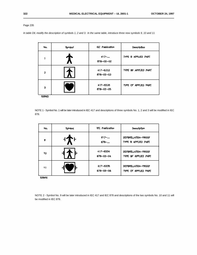
322 MEDICAL ELECTRICAL EQUIPMENT – UL 2601-1 OCTOBER 24, 1997
Page 235
In table DII, modify the description of symbols 1, 2 and 3. In the same table, introduce three new symbols 9, 10 and 11.
NOTE 1 - Symbol No. 1 will be later introduced in IEC 417 and descriptions of three symbols No. 1, 2 and 3 will be modified in IEC878.
NOTE 2 - Symbol No. 9 will be later introduced in IEC 417 and IEC 878 and descriptions of the two symbols No. 10 and 11 willbe modified in IEC 878.
OCTOBER 24, 1997 MEDICAL ELECTRICAL EQUIPMENT – UL 2601-1 323
Appendix K
Page 243 and 244
In the titles of the figures, replace:
"TYPE B EQUIPMENT", "TYPE BF EQUIPMENT", "TYPE CF EQUIPMENT" and "TYPE B, BF, CF EQUIPMENT"
respectively by
"EQUIPMENT with TYPE B APPLIED PART", "EQUIPMENT with TYPE BF APPLIED PART", "EQUIPMENT with TYPE CF APPLIEDPART" and "EQUIPMENT with TYPES B, BF and CF APPLIED PARTS".
In all four titles, print words "connection" and "connections" in small capitals.
324 MEDICAL ELECTRICAL EQUIPMENT – UL 2601-1 OCTOBER 24, 1997
Appendix L
Page 246
Modify the line of Publication 384-14 as follows:
IEC 384-14: 1993, Fixed capacitors for use in electronic equipment - Part 14: Sectional specification: Fixed capacitors for electromagneticinterference suppression and connection to the supply mains
Modify the line of publication 513 as follows
IEC 513: 1994, Fundamental aspects of safety standards for medical electrical equipment
Modify line of Publication 529 into:
IEC 529: 1989, Degrees of protection provided by enclosures (IP Code)
Just after the line of Publication 601-1: 1977, add the following standards:
IEC 601-1-1: 1992, Medical electrical equipment - Part 1: General requirements for safety.1. Collateral Standard: Safety requirements for medical electrical systems
IEC 601-1-2: 1993, Medical electrical equipment - Part 1: General requirements for safety.2. Collateral standard: Electromagnetic compatibility - Requirements and tests
IEC 601-1-3: 1994, Medical electrical equipment - Part 1: General requirements for safety.3. Collateral standard: General requirements for radiation protection in diagnostic X-ray equipment
IEC 601-1-4*: Medical electrical equipment - Part 1: General requirements for safety.4. Collateral standard: Safety requirements for programmable electronic medical systems
Page 237
After the second reference (ISO 780) add:
ISO 1000: 1981, SI units and recommendations for the use of their multiples and of certain other units
Add, at the end of the list:
ISO 10993-1: 1992, Biological evaluation of medical devices - Part 1: Guidance on selection of tests
Currently under consideration by TC 62.a
OCTOBER 24, 1997 MEDICAL ELECTRICAL EQUIPMENT – UL 2601-1 325
Pages 248/249
Replace these pages by the following:
INDEX OF DEFINED TERMS
ACCESS COVER 2.1.1 MAINS VOLTAGE 2.4.2ACCESSIBLE METAL PART 2.1.2 MAXIMUM PERMISSIBLE WORKING PRESSURE 2.11.2ACCESSIBLE PART 2.1.22 MEDICAL ELECTRICAL EQUIPMENTACCESSORY 2.1.3 (hereinafter referred to as EQUIPMENT) 2.2.15ACCOMPANYING DOCUMENTS 2.1.4 MINIMUM BREAKING LOAD 2.11.3ADJUSTABLE SETTING (of a control or MOBILE EQUIPMENT 2.2.16 limiting device) 2.9.1 MODEL OR TYPE REFERENCE (type number) 2.12.2AIR CLEARANCE 2.3.1APPLIANCE COUPLER 2.7.1 NOMINAL (value) 2.12.3APPLIANCE INLET 2.7.2 NORMAL CONDITION 2.10.7APPLIED PART 2.1.5AUXILIARY MAINS SOCKET-OUTLET 2.7.4 OPERATOR 2.12.17
OVER-CURRENT RELEASE 2.9.7BASIC INSULATION 2.3.2
PATIENT 2.12.4CATEGORY AP EQUIPMENT 2.2.2 PATIENT AUXILIARY CURRENT 2.5.4CATEGORY APG EQUIPMENT 2.2.3 PATIENT CIRCUIT 2.1.15CLASS I EQUIPMENT 2.2.4 PATIENT CONNECTION 2.1.23CLASS II EQUIPMENT 2.2.5 PATIENT LEAKAGE CURRENT 2.5.6COLD CONDITION 2.10.1 PERMANENTLY INSTALLED EQUIPMENT 2.2.17CONDUCTIVE CONNECTION 2.7.5 PORTABLE EQUIPMENT 2.2.18CONTINUOUS OPERATION 2.10.2 POTENTIAL EQUALIZATION CONDUCTOR 2.6.6CONTINUOUS OPERATION WITH INTERMITTENT LOADING 2.10.3 POWER SUPPLY CORD 2.7.17CONTINUOUS OPERATION WITH SHORT-TIME LOADING 2.10.4 PRESSURE (overpressure) 2.11.4CREEPAGE DISTANCE 2.3.3 PROPERTY INSTALLED 2.10.9
PROTECTIVE COVER 2.1.17DEFIBRILLATION-PROOF APPLIED PART 2.1.27 PROTECTIVE EARTH CONDUCTOR 2.6.7DETACHABLE POWER SUPPLY CORD 2.7.6 PROTECTIVE EARTH TERMINAL 2.6.8DIRECT CARDIAC APPLICATION 2.2.7 PROTECTIVELY EARTHED 2.6.9DOUBLE INSULATION 2.3.4DUTY CYCLE 2.10.5 RATED (value) 2.12.8
REINFORCED INSULATION 2.3.7EARTH LEAKAGE CURRENT 2.5.1EMERGENCY TROLLEY 2.12.14 SAFE WORKING LOAD 2.11.5ENCLOSURE 2.1.6 SAFETY DEVICE 2.11.6ENCLOSURE LEAKAGE CURRENT 2.5.2 SAFETY EXTRA-LOW VOLTAGE (SELV) 2.4.3EQUIPMENT (see Sub-clause 2.2.15) 2.2.11 SAFETY EXTRA-LOW VOLTAGE TRANSFORMER 2.8.3EXTERNAL TERMINAL DEVICE 2.7.7 SAFETY FACTOR 2.11.8
SAFETY HAZARD 2.12.18F-TYPE ISOLATED (FLOATING) APPLIED PART SELF-RESETTING THERMAL CUT-OUT 2.9.10 (F-TYPE APPLIED PART) 2.1.7 SELV (SAFETY EXTRA-LOW VOLTAGE) 2.4.3FIXED EQUIPMENT 2.2.12 SERIAL NUMBER 2.12.9FIXED MAINS SOCKET-OUTLET 2.7.8 SHORT-TIME OPERATION 2.10.10FIXED SETTING (of a control or limiting device) 2.9.4 SIGNAL INPUT PART 2.1.18FLAMMABLE ANAESTHETIC MIXTURE WITH AIR 2.12.15 SIGNAL OUTPUT PART 2.1.19FLAMMABLE ANAESTHETIC MIXTURE WITH SINGLE FAULT CONDITION 2.10.11 OXYGEN OR NITROUS OXIDE 2.12.16 STATIC LOAD 2.11.7FUNCTIONAL EARTH CONDUCTOR 2.6.3 STATIONARY EQUIPMENT 2.2.21FUNCTIONAL EARTH TERMINAL 2.6.4 SUPPLEMENTARY INSULATION 2.3.8
SUPPLY EQUIPMENT 2.1.21HAND-HELD EQUIPMENT 2.2.13 SUPPLY MAINS 2.12.10HIGH VOLTAGE 2.4.1HYDRAULIC TEST PRESSURE 2.11.1 TERMINAL DEVICE 2.7.16
THERMAL CUT-OUT 2.9.12INTERCONNECTION TERMINAL DEVICE 2.7.9 THERMOSTAT 2.9.13INTERMITTENT OPERATION 2.10.6 TOOL 2.12.12INTERNAL ELECTRICAL POWER SOURCE 2.1.9 TOTAL LOAD 2.11.9INTERNALLY POWERED EQUIPMENT 2.2.29 TRANSPORTABLE EQUIPMENT 2.2.23
TYPE B APPLIED PART 2.1.24LEAKAGE CURRENT 2.5.3 TYPE BF APPLIED PART 2.1.25LIVE 2.1.10 TYPE CF APPLIED PART 2.1.26
MAINS CONNECTOR 2.7.10 USER 2.12.13MAINS PART 2.1.12MAINS PLUG 2.7.11MAINS TERMINAL DEVICE 2.7.12

326 MEDICAL ELECTRICAL EQUIPMENT – UL 2601-1 OCTOBER 24, 1997
No Text On This Page
Subjects 2601 (187, 544) 1285 Walt Whitman RoadMelville, New York 11747July 16, 1997
TO: Casualty Council of Underwriters Laboratories Inc.,Electrical Council of Underwriters Laboratories Inc.,Subscribers to UL's Listing and Classification Services for
Medical Electrical Equipment, (PIDF)Medical and Dental Equipment, (KFBQ)X-Ray Equipment (ZQOR)
SUBJECT: Announcement of UL Classification Service of Electrode Lead Wires and Patient Cables In Accordance With Code ofFederal Regulations
Electrode Lead Wires and Patient Cables can be submitted for evaluation and Classification in accordance with Code of Federal Regulations21 CFR Section 898.12.
On May 9, 1997, the U.S. FDA issued a final rule announcing the agency's first mandatory standard. The requirements concern theconstruction and performance of electrode lead wires and patient cables. The requirements are published in the Code of Federal Regulations21 CFR Section 898.12. Electrode lead wires and patient cables must comply with Amendment 2 (1995) of IEC 601-1 (1988), subclause56.3 paragraph c, which is shown in Appendix A.
This new service will allow manufacturers to have products evaluated in accordance with the performance and regulatory requirementsindicated in 21 CFR Section 898.12. Upon successful evaluation and testing, by UL acting as an independent third-party testing agency,products will be eligible to bear UL's Classification Marking that indicates compliance with the indicated regulations. Investigations of theseproducts will be covered under a new category, Electrode Lead Wires and Patient Cables, (PIEY). The compatibility of these devices for usewith specific medical equipment has not been investigated. Equipment evaluated for fire, shock and mechanical hazards is covered in thefollowing categories: Medical and Dental Equipment, (KFBQ), Medical Electrical Equipment, (PIDF), and X-Ray Equipment (ZQOR)
These products are designed for professional use by qualified personnel in hospitals, nursing homes, medical care centers, medical and dentaloffices, and similar health care facilities in accordance with the instructions provided by the manufacturer. The physiological effects of theseproducts have not been investigated. The effect on a patient of simultaneous use of this equipment with other electrical apparatus has notbeen investigated.
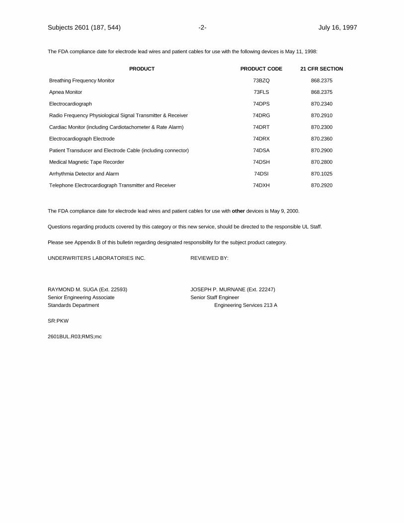
Subjects 2601 (187, 544) -2- July 16, 1997
The FDA compliance date for electrode lead wires and patient cables for use with the following devices is May 11, 1998:
PRODUCT PRODUCT CODE 21 CFR SECTION
Breathing Frequency Monitor 73BZQ 868.2375
Apnea Monitor 73FLS 868.2375
Electrocardiograph 74DPS 870.2340
Radio Frequency Physiological Signal Transmitter & Receiver 74DRG 870.2910
Cardiac Monitor (including Cardiotachometer & Rate Alarm) 74DRT 870.2300
Electrocardiograph Electrode 74DRX 870.2360
Patient Transducer and Electrode Cable (including connector) 74DSA 870.2900
Medical Magnetic Tape Recorder 74DSH 870.2800
Arrhythmia Detector and Alarm 74DSI 870.1025
Telephone Electrocardiograph Transmitter and Receiver 74DXH 870.2920
The FDA compliance date for electrode lead wires and patient cables for use with other devices is May 9, 2000.
Questions regarding products covered by this category or this new service, should be directed to the responsible UL Staff.
Please see Appendix B of this bulletin regarding designated responsibility for the subject product category.
UNDERWRITERS LABORATORIES INC. REVIEWED BY:
RAYMOND M. SUGA (Ext. 22593) JOSEPH P. MURNANE (Ext. 22247)Senior Engineering Associate Senior Staff EngineerStandards Department Engineering Services 213 A
SR:PKW
2601BUL.R03;RMS;mc
Subjects 2601 (187, 544) -A1- July 1997
A P P E N D I X A
EXCERPT OF REQUIREMENT FROM AMENDMENT 2 OF IEC 601-1
56.3 Connections - General
Add the following new item with an asterisk in front:
*c) Any connector in a lead having a CONDUCTIVE CONNECTION to a PATIENT shall be constructed in such a manner that noCONDUCTIVE CONNECTION of that part of the said connector which is remote from the PATIENT can contact earth or possible hazardousvoltages.
Compliance is checked by inspection and by applying to the conductive connection of that part of the connector identified above those ofthe following tests which are applicable:
– the said part shall not come into contact with a flat conductive surface of not less than 100 mm diameter;
– for single-pole connectors, the straight unjointed test finger with the same dimensions as the standard test finger of figure 7shall not make electrical contact with the said part if applied in the least favorable position against the access openings with a forceof 10 N ± 2 N;
– if able to be plugged into a mains socket, the said part shall be protected from making contact with parts of mains voltage byinsulating means providing a CREEPAGE DISTANCE of at least 1.0 mm and a dielectric strength of 1500 V.

Subjects 2601 (187, 544) -A2- July 1997
No Text On This Page
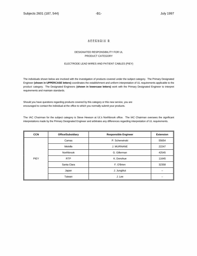
Subjects 2601 (187, 544) -B1- July 1997
A P P E N D I X B
DESIGNATED RESPONSIBILITY FOR ULPRODUCT CATEGORY
ELECTRODE LEAD WIRES AND PATIENT CABLES (PIEY)
The individuals shown below are involved with the investigation of products covered under the subject category. The Primary DesignatedEngineer (shown in UPPERCASE letters) coordinates the establishment and uniform interpretation of UL requirements applicable to theproduct category. The Designated Engineers (shown in lowercase letters) work with the Primary Designated Engineer to interpretrequirements and maintain standards.
Should you have questions regarding products covered by this category or this new service, you areencouraged to contact the individual at the office to which you normally submit your products.
The IAC Chairman for the subject category is Steve Hewson at UL's Northbrook office. The IAC Chairman oversees the significantinterpretations made by the Primary Designated Engineer and arbitrates any differences regarding interpretation of UL requirements.
CCN Office/Subsidiary Responsible Engineer Extension
PIEY RTP K. Donohue 11645
Camas P. Scherwinski 55654
Melville J. MURNANE 22247
Northbrook G. Gillerman 42545
Santa Clara F. O'Brien 32358
Japan J. Jungblut –
Taiwan J. Lee –

Subjects 2601 (187, 544) -B2- July 1997
No Text On This Page
Subjects 2601-1 (544, 187, 3101-1) 1285 Walt Whitman RoadMelville, New York 11747-3081May 10, 1999
TO: Electrical Council of Underwriters Laboratories Inc.,Subscribers to UL's Standards Service for
Medical Electrical EquipmentMedical and Dental EquipmentX-Ray Equipment
Manufacturers ofMedical and Dental Equipment, Professional (KFBQ)Medical and Dental Equipment, Professional – Disposal Systems and Accessories
(KFBY)Power Supplies for Use in Health Care Facilities (KFCG)Uninterruptible Power Supplies for Use In Health Care Facilities (KFFG)Magnetic Resonance Imaging Equipment (PAZB)Medical Equipment Classified in Accordance with Specified Medical Standards (PIKF)Medical and Dental Equipment Power Supplies – Component (QQHM2)X-Ray Equipment (ZQOR)X-Ray Equipment, Accessories (ZQVQ)
SUBJECT: Reminder of Effective Date for Withdrawal of UL 544 and UL 187
UL announced, in its bulletin dated June 7, 1994, the schedule that would apply for the withdrawal of UL 544 and UL 187, the Standard forMedical and Dental Equipment and the Standard for X-Ray Equipment, respectively. These standards will eventually be replaced by UL 2601-1, the Standard for Medical Electrical Equipment; Part 1 – General Requirements. UL's June 7, 1994 bulletin stated that UL 544 and UL 187could be used to evaluate medical and dental products until January 1, 2003, after which UL 2601-1 will be exclusively used for the evaluationof new products. As of January 1, 2005, all Listed, Classified and Recognized medical and dental products, where UL 544 or 187 was usedto evaluate the product, must comply with UL 2601-1. It is the manufacturer's responsibility to re-submit these products to UL (for UL 2601-1evaluation) if UL coverage is to be maintained. The UL coverage will be terminated for those products not found to comply by January 1, 2005.
Date Action
Jan 1, 2003 New products will be evaluated to UL 2601-1
Jan 1, 2005 All products comply with UL 2601-1.UL 544 and 187 withdrawn
Subject 2601-1 (544, 187, 3101-1) 2 May 10, 1999
Though the first date is still three years away, UL recommends that manufacturers contact us as soon as practical to develop strategies fortheir products and the coming transfer dates. An early approach to this work will result in the smoothest transition, with lowest costs and leastimpact on the manufacturer's production.
There are several specialized UL product categories which presently reference UL 544 or UL 187 to assist in the investigation of anymedical/dental aspects of product constructions. They are to be addressed as indicated below.
The following categories, and the corresponding component categories, will be withdrawn after January 1, 2005 since all products coveredunder them will be covered under category PIDF (following investigation to determine compliance with UL 2601-1). Consequently, anyproducts in the following categories, which have not been evaluated to UL 2601-1, will no longer retain UL Listing or Classification after thatdate. No File Review will be conducted.
KFBQ – Medical and Dental Equipment, ProfessionalPAZB – Magnetic Resonance Imaging EquipmentZQOR – X-Ray EquipmentZQVQ – X-Ray Equipment, Accessories
The following categories will remain after January 1, 2005; therefore, it will be necessary for UL staff to contact manufacturers to review theirproducts (conduct a File Review) to determine compliance of existing products with the UL 2601-1 requirements:
KFBY – Medical and Dental Equipment, Professional – Disposal Systems and AccessoriesKFCG – Power Supplies for Use in Health Care FacilitiesKFFG – Uninterruptible Power Supplies for Use In Health Care FacilitiesQQHM2 – Medical and Dental Equipment Power Supplies – Component
The guide cards covering these categories (and any UL standards referencing UL 544 and/or UL 187 for medical/dental aspects of theproduct) will be revised to reference only UL 2601-1 and delete any references to UL 544 or UL 187. Accordingly, Listing, Recognition, orClassification of products that have not been evaluated to UL 2601-1 requirements will be discontinued as of January 1, 2005, and use of theUL Mark will cease on that date.
Similar Changes in "Certified for Canada" Product Categories
As a related issue, UL is also announcing similar changes in UL categories that cover the Listing, Recognition and/or Classification of productsto Canadian National Standards. CSA 22.2 No. 114, which corresponds to UL 187, is being discontinued as of January 1, 2005. CSA 22.2No. 125, which corresponds to UL 544, is also being discontinued by January 1, 2005. After that date, all equipment previously manufacturedand certified to the requirements of standards C22.2 No. 114 or C22.2 No. 125 must comply with the requirements of CSA Standard C22.2No. 601.1, Part 2 Series, and Collateral Standards, as applicable. Consequently, UL will have to review the following product categories tomake sure all products comply with CSA 22.2 No. 601.1 as of January 1, 2005:
KFBQ7/8 – Medical and Dental Equipment, Professional, Certified for Canada – ComponentsKFBY7/8 – Professional Disposal Systems and Accessories, Certified for
Canada – ComponentsKFCG7 – Power Supplies for Use in Health Care Facilities, Certified for CanadaKFFG7/8 – Uninterruptible Power Supplies for Use in Health Care Facilities,
Certified for CanadaPAZB7/8 – Magnetic Resonance Imaging Equipment/Components

Subject 2601-1 (544, 187, 3101-1) 3 May 10, 1999
QQHM8 – Power Supplies, Medical and Dental, Certified for Canada – ComponentsZQOR7/8 – X-Ray Equipment, Certified for Canada – ComponentsZQVQ7 – X-Ray Equipment, Accessories, Certified for Canada
Non-Medical X-Ray Equipment
As announced above, UL product categories ZQOR and ZQVQ will cease to exist after the January 1, 2005 implementation date. It isanticipated that most of the medical-equipment x-ray-type products will relocated to category PIDF; however, there are some non-medical typesof x-ray equipment (such as baggage inspection systems, open field inspection systems for air frames and piping, etc.) that will need to berelocated to a new UL product category (because of its non-medical application). UL has decided that category NYOK is a suitable place forthat equipment. The base standard that UL uses to investigate products submitted under NYOK/NYOK2 is UL 3101-1 which correspondsto IEC 601010-1. The UL contact personnel for categories NYOK and NYOK2 is listed in Appendix C. Manufactures should contact UL staffwell in advance of the implementation date to develop a plan for continued coverage.
This bulletin should be kept with your copy of the standard.
Questions regarding interpretation of requirements should be directed to the responsible UL Staff. Please see Appendix A, Appendix B, andAppendix C of this bulletin regarding designated responsibility for the subject product categories.
UNDERWRITERS LABORATORIES INC. REVIEWED BY:
RAYMOND M. SUGA (Ext. 22593) JOSEPH P. MURNANE (Ext. 22247)Senior Engineering Associate Senior Staff EngineerStandards Department Engineering Services 3013AMELMELVILLE OFFICE MELVILLE OFFICE(516) 271-6200 (516) 271-6200Fax: (516) 439-6021 Fax: (516) 439-6042E-mail: [email protected] E-mail: [email protected]
SR:LS
2601BUL.R04;RMS;mc
Subject 2601-1 (544, 187, 3101-1) 4 May 10, 1999
No Text On This Page

Subject 2601-1 (544, 187, 3101-1) A1 May 1999
A P P E N D I X A
DESIGNATED RESPONSIBILITY FOR ULPRODUCT CATEGORIES
KFBQ, Medical and Dental Equipment, ProfessionalKFBY, Medical and Dental Equipment, Professional – Disposal Systems and AccessoriesKFCG, Power Supplies for Use in Healthcare FacilitiesKFFG, Uninterruptible Power Supplies for Use in Healthcare FacilitiesPAZB, Magnetic Resonance Imaging EquipmentPIKF, Medical Equipment Classified in Accordance with Specified Medical StandardsQQHM2, Medical and Dental Equipment Power SuppliesZQOR, X-Ray EquipmentZQVQ, X-Ray Equipment, Accessories
The individuals shown in the following tables are involved with the investigation of products covered under the subject categories. The PrimaryDesignated Engineer (shown in UPPERCASE letters) coordinates the establishment and uniform interpretation of UL requirementsapplicable to the product categories. The Designated Engineers (shown in lowercase letters) work with the Primary Designated Engineerto interpret requirements and maintain standards.
Should you have questions regarding any adopted requirements that affect your product, you are encouraged to contact the individual at the office to which you normally submit your products.
The Industry Advisory Conference (IAC) Chairman for the subject categories is Gary Schrempp at UL's RTP office. The IAC Chairmanoversees the significant interpretations made by the Primary Designated Engineer and arbitrates any differences regarding interpretation ofUL requirements.
CCN Office/Subsidiary Responsible Engineer Extension
KFBQ
Camas R. Boonstra 55652
Melville J. MURNANE 22247
Northbrook D. Hallerberg 43224
RTP P. Gwynn 11697
Santa Clara B. Blair 32024
Canada B. Black 416-757-3611
UK D. Bejnarowicz 44-1483-302-130
Taiwan J. Lee 886-2-896-7790
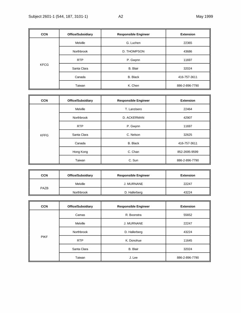
Subject 2601-1 (544, 187, 3101-1) A2 May 1999
CCN Office/Subsidiary Responsible Engineer Extension
KFCG
Melville G. Luchen 22365
Northbrook D. THOMPSON 43686
RTP P. Gwynn 11697
Santa Clara B. Blair 32024
Canada B. Black 416-757-3611
Taiwan K. Chen 886-2-896-7790
CCN Office/Subsidiary Responsible Engineer Extension
KFFG
Melville T. Lanzisero 22464
Northbrook D. ACKERMAN 42907
RTP P. Gwynn 11697
Santa Clara C. Nelson 32625
Canada B. Black 416-757-3611
Hong Kong C. Chan 852-2695-9599
Taiwan C. Sun 886-2-896-7790
CCN Office/Subsidiary Responsible Engineer Extension
PAZBMelville J. MURNANE 22247
Northbrook D. Hallerberg 43224
CCN Office/Subsidiary Responsible Engineer Extension
PIKF
Camas R. Boonstra 55652
Melville J. MURNANE 22247
Northbrook D. Hallerberg 43224
RTP K. Donohue 11645
Santa Clara B. Blair 32024
Taiwan J. Lee 886-2-896-7790

Subject 2601-1 (544, 187, 3101-1) A3 May 1999
CCN Office/Subsidiary Responsible Engineer Extension
QQHM2
Camas P. Scherwinski 55654
Melville G. Luchen 22365
Northbrook D. THOMPSON 43686
RTP P. Gwynn 11697
Santa Clara B. Blair 32024
Canada B. Black 416-757-3611
UK D. Bejnarowicz 44-1483-302-130
CCN Office/Subsidiary Responsible Engineer Extension
ZQOR
Melville J. MURNANE 22247
Northbrook D. Hallerberg 43224
RTP P. Gwynn 11697
Santa Clara B. Blair 32024
Canada B. Black 416-757-3611
Europe D. Bejnarowicz 44-1483-302-130
CCN Office/Subsidiary Responsible Engineer Extension
ZQVQ
Melville J. MURNANE 22247
Northbrook D. Hallerberg 43224
RTP P. Gwynn 11697
Santa Clara B. Blair 32024
Canada B. Black 416-757-3611
Subject 2601-1 (544, 187, 3101-1) A4 May 1999
No Text On This Page
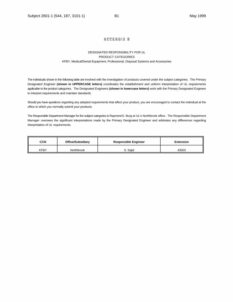
Subject 2601-1 (544, 187, 3101-1) B1 May 1999
A P P E N D I X B
DESIGNATED RESPONSIBILITY FOR ULPRODUCT CATEGORIES
KFBY, Medical/Dental Equipment, Professional, Disposal Systems and Accessories
The individuals shown in the following table are involved with the investigation of products covered under the subject categories. The PrimaryDesignated Engineer (shown in UPPERCASE letters) coordinates the establishment and uniform interpretation of UL requirementsapplicable to the product categories. The Designated Engineers (shown in lowercase letters) work with the Primary Designated Engineerto interpret requirements and maintain standards.
Should you have questions regarding any adopted requirements that affect your product, you are encouraged to contact the individual at theoffice to which you normally submit your products.
The Responsible Department Manager for the subject categories is Raymond E. Burg at UL's Northbrook office. The Responsible DepartmentManager oversees the significant interpretations made by the Primary Designated Engineer and arbitrates any differences regardinginterpretation of UL requirements.
CCN Office/Subsidiary Responsible Engineer Extension
KFBY Northbrook S. Sajid 43503
Subject 2601-1 (544, 187, 3101-1) B2 May 1999
No Text On This Page
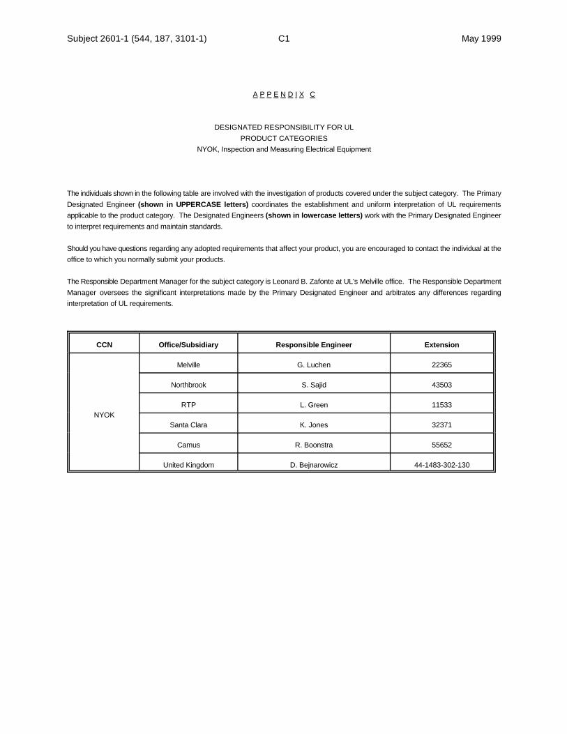
Subject 2601-1 (544, 187, 3101-1) C1 May 1999
A P P E N D I X C
DESIGNATED RESPONSIBILITY FOR ULPRODUCT CATEGORIES
NYOK, Inspection and Measuring Electrical Equipment
The individuals shown in the following table are involved with the investigation of products covered under the subject category. The PrimaryDesignated Engineer (shown in UPPERCASE letters) coordinates the establishment and uniform interpretation of UL requirementsapplicable to the product category. The Designated Engineers (shown in lowercase letters) work with the Primary Designated Engineerto interpret requirements and maintain standards.
Should you have questions regarding any adopted requirements that affect your product, you are encouraged to contact the individual at theoffice to which you normally submit your products.
The Responsible Department Manager for the subject category is Leonard B. Zafonte at UL's Melville office. The Responsible DepartmentManager oversees the significant interpretations made by the Primary Designated Engineer and arbitrates any differences regardinginterpretation of UL requirements.
CCN Office/Subsidiary Responsible Engineer Extension
NYOK
Melville G. Luchen 22365
Northbrook S. Sajid 43503
RTP L. Green 11533
Santa Clara K. Jones 32371
Camus R. Boonstra 55652
United Kingdom D. Bejnarowicz 44-1483-302-130

Subject 2601-1 (544, 187, 3101-1) C2 May 1999
No Text On This Page