268 ul-csa anl en 47-13 - reo-usa, inc. · 268_ul-csa_anl_en_47-13.doc 21.11.2013 reovib control...
TRANSCRIPT
268_UL-CSA_ANL_EN_47-13.DOC 21.11.2013
REOVIB Control Equipment for the Vibratory Feeder Industry
MFS 268
Frequency Converter for Vibratory Feeders
UL / CSA - Version
REOVIB MFS 268 UL/CSA Operating Instructions
1
ELEKTRONIK
Technical safety instructions for the user
This description contains the necessary information for the correct application of the product described below. It is intended for use by technically qualified personal. Qualified personnel are persons who, because of their training, experience and position as well as their knowledge of appropriate standards, regulations, health and safety requirements and working conditions, are authorised to be responsible for the safety of the equipment, at all times, whilst carrying out their nor-mal duties and are therefore aware of, and can report, possible hazards (Definition of qualified employees according to IEC 364) Safety Instructions The following instructions are provided for the personal safety of operators and also for the protection of the described product and connected equipment.
Warning! Hazardous Voltage Failure to observe can kill, cause serious injury or damage
• Isolate from mains before installation or dismantling work, as well as for fuse changes or post installa-
tion modifications. • Observe the prescribed accident prevention and safety rules for the specific application. • Before putting into operation check if the rated voltage for the unit conforms with the local supply
voltage. • Emergency stop devices must be provided for all applications. Operation of the emergency stop must
inhibit any further uncontrolled operation. • The electrical connecting terminals must be covered ! • Earth bonding must be tested for integrity after in stallation. Specified Use The units described herein are electrical controllers for installation in industrial plant. They are designed for controlling vibratory feeders.
For use in NFPA 79 Applications only Adapters providing field wiring means are available from REO ELEKTRONIK AG. Refer to REO ELEKTRONIK AG.
!
REOVIB MFS 268 UL/CSA Operating Instructions
2
ELEKTRONIK
Contents Technical safety instructions for the user ..................................................................................................... 1
1.0 General ................................................................................................................................................... 3
2.0 Function .................................................................................................................................................. 3
2.1 Track control ....................................................................................................................................... 4
2.2 Operating with two speeds (2 set points for coarse/fine switching) .................................................... 4
2.3 Control inputs and output .................................................................................................................... 4
2.3.1 Enable input ..................................................................................................................................... 4
2.3.2 Sensor input for track control ........................................................................................................... 4
2.3.3 External set point ............................................................................................................................. 4
2.3.4 Output status relay ........................................................................................................................... 5
2.3.5 Time-Out output 24 VDC ................................................................................................................. 5
2.3.6 Air valve output 24 VDC ................................................................................................................... 5
2.4 Display ................................................................................................................................................ 5
3.0 Construction ............................................................................................................................................ 5
3.1 Enclosed units ..................................................................................................................................... 5
3.2 Panel mounting units........................................................................................................................... 5
4.0 Technical Data ........................................................................................................................................ 6
5.0 Ordering Codes (UL / CSA units) ........................................................................................................... 6
6.0 Declaration of Conformity ....................................................................................................................... 6
7.0 Settings ................................................................................................................................................... 7
8.0 Control elements ..................................................................................................................................... 8
8.1 Settings ............................................................................................................................................... 8
9.0 Commissioning ....................................................................................................................................... 9
9.1 Assembling position ............................................................................................................................ 9
9.2 Preliminary steps ................................................................................................................................. 9
9.2.1 Important points ............................................................................................................................... 9
9.2.1.1 Operating frequency of the feeder coil .......................................................................................... 9
9.2.1.2 Measurement of the output voltage and current ........................................................................... 9
9.3 Putting the equipment into operation ................................................................................................ 10
9.4 Switch-on frequency of the power supply ......................................................................................... 10
10.0 Setting Instructions ............................................................................................................................. 11
10.1 User adjustment of throughput ........................................................................................................ 11
10.2 Tuning the feed system ................................................................................................................... 11
10.2.1 Feeder settings ............................................................................................................................ 11
10.2.2 Track control ................................................................................................................................ 12
10.2.3 Sensor time out ............................................................................................................................ 12
10.2.4 Set point source ........................................................................................................................... 12
10.2.5 Pulse feed .................................................................................................................................... 13
10.2.6 Regulation mode .......................................................................................................................... 13
10.2.6.1 Instructions for using regulation mode ...................................................................................... 14
10.2.6.2 Mounting the accelerometer ..................................................................................................... 14
10.2.6.3 Relationship between acceleration and amplitude ................................................................... 16
10.2.6.4 Instructions for setting up the controller in regulation mode ..................................................... 16
10.2.6.5 Determining the resonant frequency ......................................................................................... 16
10.2.6.6 Optimisating controller in regulation mode ............................................................................... 17
10.2.6.7 Displays ..................................................................................................................................... 17
10.2.7 Display actual current and frequency .......................................................................................... 18
10.2.8 Save selected parameters ........................................................................................................... 18
10.2.9 Recall user or factory settings ...................................................................................................... 18
10.2.10 Hide parameter menus .............................................................................................................. 18
11.0 Error messages / ERROR reset ......................................................................................................... 19
12.0 Connections for enclosed construction (IP 54): 6-8 A Units ............................................................... 20
12.1 Connections for enclosed construction (IP 54): 12 A Units ............................................................ 21
12.2 Connections for enclosed construction (IP 54): 16 A Units ............................................................ 22
13.0 Connections for panel mounting construction (IP 20): 3 A, 6 A, 8 A .................................................. 23
13.1 Connections for panel mounting construction (IP 20): 16A ............................................................ 24
14.0 Dimensions for 3 A, 6 A, 8 A Units ..................................................................................................... 25
14.1 Dimensions of enclosed construction (IP 54) 12 A ......................................................................... 26
14.2 Dimensions of enclosed construction (IP 54) 16 A ......................................................................... 26
14.3 Dimensions of Panel mounting construction (IP 20) 16 A .............................................................. 27
A 1.0 Service appendix ............................................................................................................................... 28
A 2.0 Accessories / Spare Parts ................................................................................................................. 31
REOVIB MFS 268 UL/CSA Operating Instructions
3
ELEKTRONIK
1.0 General
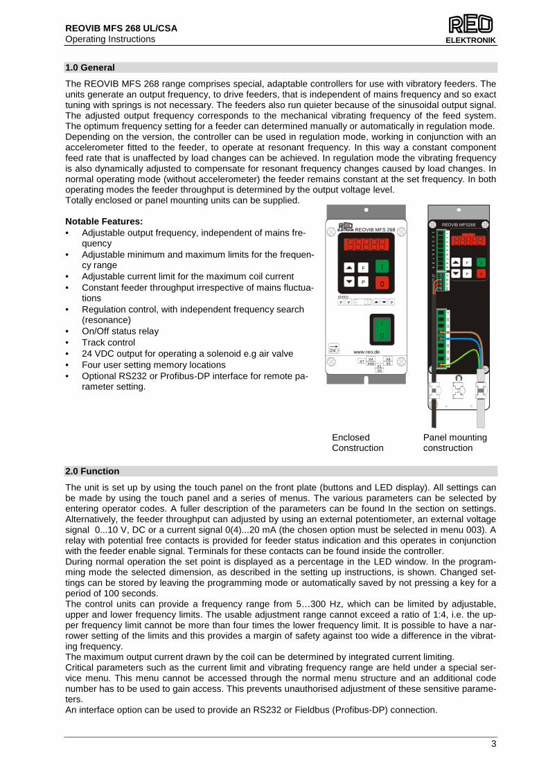
The REOVIB MFS 268 range comprises special, adaptable controllers for use with vibratory feeders. The units generate an output frequency, to drive feeders, that is independent of mains frequency and so exact tuning with springs is not necessary. The feeders also run quieter because of the sinusoidal output signal. The adjusted output frequency corresponds to the mechanical vibrating frequency of the feed system. The optimum frequency setting for a feeder can determined manually or automatically in regulation mode. Depending on the version, the controller can be used in regulation mode, working in conjunction with an accelerometer fitted to the feeder, to operate at resonant frequency. In this way a constant component feed rate that is unaffected by load changes can be achieved. In regulation mode the vibrating frequency is also dynamically adjusted to compensate for resonant frequency changes caused by load changes. In normal operating mode (without accelerometer) the feeder remains constant at the set frequency. In both operating modes the feeder throughput is determined by the output voltage level. Totally enclosed or panel mounting units can be supplied. Notable Features: • Adjustable output frequency, independent of mains fre-
quency • Adjustable minimum and maximum limits for the frequen-
cy range • Adjustable current limit for the maximum coil current • Constant feeder throughput irrespective of mains fluctua-
tions • Regulation control, with independent frequency search
(resonance) • On/Off status relay • Track control • 24 VDC output for operating a solenoid e.g air valve • Four user setting memory locations • Optional RS232 or Profibus-DP interface for remote pa-
rameter setting. 2.0 Function
The unit is set up by using the touch panel on the front plate (buttons and LED display). All settings can be made by using the touch panel and a series of menus. The various parameters can be selected by entering operator codes. A fuller description of the parameters can be found In the section on settings. Alternatively, the feeder throughput can adjusted by using an external potentiometer, an external voltage signal 0...10 V, DC or a current signal 0(4)...20 mA (the chosen option must be selected in menu 003). A relay with potential free contacts is provided for feeder status indication and this operates in conjunction with the feeder enable signal. Terminals for these contacts can be found inside the controller. During normal operation the set point is displayed as a percentage in the LED window. In the program-ming mode the selected dimension, as described in the setting up instructions, is shown. Changed set-tings can be stored by leaving the programming mode or automatically saved by not pressing a key for a period of 100 seconds. The control units can provide a frequency range from 5…300 Hz, which can be limited by adjustable, upper and lower frequency limits. The usable adjustment range cannot exceed a ratio of 1:4, i.e. the up-per frequency limit cannot be more than four times the lower frequency limit. It is possible to have a nar-rower setting of the limits and this provides a margin of safety against too wide a difference in the vibrat-ing frequency. The maximum output current drawn by the coil can be determined by integrated current limiting. Critical parameters such as the current limit and vibrating frequency range are held under a special ser-vice menu. This menu cannot be accessed through the normal menu structure and an additional code number has to be used to gain access. This prevents unauthorised adjustment of these sensitive parame-ters. An interface option can be used to provide an RS232 or Fieldbus (Profibus-DP) connection.
Enclosed Construction
Panel mounting construction
Ø 5,0
21 22 23 24 25 26 2
7 28 29
1
2 3 4
5
6 7 8
931 32 33 34
REOVIB MFS268
F I
0P
SPEED
P P P
REOVIB MFS 268
X1
X4X7
X6
X0
X40 X5
P
F I
0
www.reo.de

REOVIB MFS 268 UL/CSA Operating Instructions
4
ELEKTRONIK
t ON t OFF
Sensor
Feeder ON
OFF
ON
OFF
Soft Start Soft Stop
2.1 Track control
The output can be switched ON and OFF from a track component sensor, using internal, adjustable time delays (ton and toff). The queue of components rises above and drops below the track sensor position. The controller output switches on when the sensor cannot detect product and a switch-on time delay has elapsed. The output is switched off when product is detected and a switch-off time delay has elapsed (FULL displayed in the LED window). Gaps in the product feed cause resetting of the time delay. The time will always be precise from the last or first component, respectively. The ON and OFF time delays are set in the pro-gramming menu. The first decimal point in the display blinks to indicate that an internal timer is running. An additional “Sensor-Time-out“ timer is started when the feeder switches on. This can be set (30...240 sec.) to switch off the feeder if no product is sensed in the time out period. The status relay indicates that the feeder is not running and the LED window displays ERROR and SE alternately. This function is op-tional and must be selected in the Track Settings Menu with function EEn = 1. 2.2 Operating with two speeds (2 set points for coa rse/fine switching)
Coarse/Fine control can be used instead of track control (Menu C 003). The second set point is activated through the same sensor input that is used for track control. Either contacts or a 24 VDC signal can be used to change the set point from coarse to fine. The second set point is activated, immediately, by apply-ing a 24 V signal (The track control function is invalid) 2.3 Control inputs and output
2.3.1 Enable input
External switch or 24 VDC signal voltage. External control function to switch the power output ON or OFF e.g. Networking of several controllers from a central PLC. 2.3.2 Sensor input for track control
Sensor for monitoring the queue of components on the track or an input for switching to the second set point 24 VDC (PNP). 2.3.3 External set point
The feeder amplitude set point can be provided from and external, analog 0...10 V, DC, 0(4)...20 mA, or a 10 kR Potentiometer. Parameter ESP in Menu C003 must be set to I, for an external set point source to be used. If a potentiometer is used, must additionally parameter "POT" set to I. (not on 16A IP 20 units). Setting the minimum output value when external set point = 0: Before changing the ESP parameter to accept an external set point source, the minimum value can be adjusted by using the cursor keys, on the front panel, and this will remain when the ESP is changed over from 0 to I.

REOVIB MFS 268 UL/CSA Operating Instructions
5
ELEKTRONIK
2.3.4 Output status relay
Status-Relay contact 250 V/1 A (changeover). Relay closes when the feeder is running – the relay opens when there is no enable signal or a fault displayed.
2.3.5 Time-Out output 24 VDC
"time Out" message active, if after adjusted time no material is recognized by the sensor (adjustable with parameter "E."). (not on IP 20 units) 2.3.6 Air valve output 24 VDC
Output for air blast, comes on with feeder and switches off, 4 sec., after feeder stops (not on IP 20 units) 2.4 Display
Initialisation phase, when supply voltage is connected (left decimal point blinks).
Normal Mode: The throughput set point is displayed
Output switched off using the `0` button Unit inhibited by the enable input Output switched off by the track control sensor Under voltage, input voltage is to low.
3.0 Construction
The units are available as stand-alone, enclosed or panel mounting versions . 3.1 Enclosed units
• Mains switch • Touch panel with display • Mains cable with plug • Output cable or output socket for connecting to the feed system • Sensor socket. The standard unit has provision for 24 VDC sensors with a PNP output 3.2 Panel mounting units
• Touch panel with display
• Terminals for electrical connections
• Screw hole fixings for mounting

REOVIB MFS 268 UL/CSA Operating Instructions
6
ELEKTRONIK
4.0 Technical Data
Model Type MFS 268 / 3A MFS 268 / 6A MFS 268 / 8A MFS 268 / 12A MFS 268 / 16A Supply voltage 110 V, 240 V +/- 10 %, 50/60 Output 0...95 V, 0...205 V Output current Max. 3 A Max. 6 A Max. 8 A Max. 12A Max 16 A Recommended * Protection
10 A Anti-surge 16 A Anti-surge 16 A Anti-surge 16 A Anti-surge 16 A Anti-surge Type D current trip device
Enable 24 V, DC input (connect to internal 24 V reference) Status relay Change-over contacts, 250V, 1 A Sensor supply 24 V, DC, 100 mA Sensor type PNP output Status output Relay, change-over contact 1A, 250 VAC , 60 VDC Switch-on frequency of the power supply
wait 5 seconds until resetting the power supply
Solenoid valve out-put
24 VDC / 50 mA switched with feeder unit (PNP), short-circuit protected
not provided at IP 20 versions
Operating tempera-ture
0...+45 °C
Storage temperature -10...+80 °C Altitude 1000 m 0,5 % rated current reduction for each additional 100 m
* The units are provided with switch-on, current da mping. However it is still possible that some internal capacitor, energising, current spikes will be generated, especially when several units are switched on simultaneously. Therefore, fuses and ov erload trips should have anti current surge characteristics. 5.0 Ordering Codes (UL / CSA units)
Type Order Code Construction REOVIB MFS 268-3A–IP 20
621607 3 A, Panel mounting with track control and accelerometer regulation
REOVIB MFS 268-6A–IP 20 621614
6 A, Panel mounting with track control and accelerometer regulation
REOVIB MFS 268-8A–IP 20 621621
8 A, Panel mounting with track control and accelerometer regulation
REOVIB MFS 268-16A–IP 20 621110
16 A, Panel mounting with track control and accelerometer regulation
REOVIB MFS 268-6A–IP 54 626825
6 A, Enclosed construction with track control and accelerometer regulation
REOVIB MFS 268-8A–IP 54 626845
8 A, Enclosed construction with track control and accelerometer regulation
REOVIB MFS 268-12A–IP 54 626865
12 A, Enclosed construction with track control and accelerometer regulation
REOVIB MFS 268-16A–IP 54 626885
16 A, Enclosed construction with track control and accelerometer regulation
For use in NFPA 79 Applications only E217179 Adapters providing field wiring means are available from REO ELEKTRONIK AG. Refer to REO ELEKTRONIK AG. 6.0 Declaration of Conformity
We declare that these products conform with the following standards: EN 61000-6-4 and EN 61000-6-2 in accordance with the regulations of guidelines 2004/108/EC. REO ELEKTRONIK AG, D-42657 Solingen
RoHSCOMPLAINT
REOVIB MFS 268 UL/CSA Operating Instructions
7
ELEKTRONIK
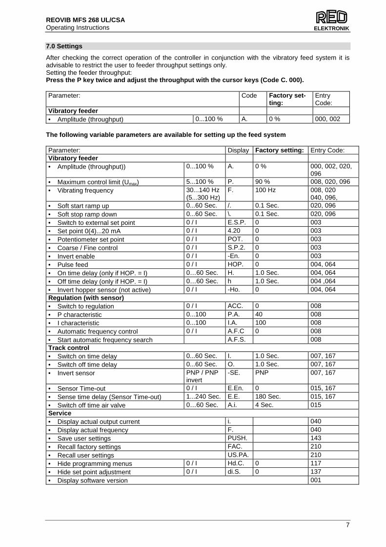
7.0 Settings
After checking the correct operation of the controller in conjunction with the vibratory feed system it is advisable to restrict the user to feeder throughput settings only. Setting the feeder throughput: Press the P key twice and adjust the throughput wit h the cursor keys (Code C. 000). Parameter: Code Factory se t-
ting: Entry Code:
Vibratory feeder • Amplitude (throughput) 0...100 % A. 0 % 000, 002
The following variable parameters are available for setting up the feed system Parameter: Display Factory se tting: Entry Code: Vibratory feeder • Amplitude (throughput)) 0...100 % A. 0 % 000, 002, 020,
096 • Maximum control limit (Umax) 5...100 % P. 90 % 008, 020, 096 • Vibrating frequency 30...140 Hz
(5...300 Hz) F. 100 Hz 008, 020
040, 096, • Soft start ramp up 0...60 Sec. /. 0.1 Sec. 020, 096 • Soft stop ramp down 0...60 Sec. \. 0.1 Sec. 020, 096 • Switch to external set point 0 / I E.S.P. 0 003 • Set point 0(4)...20 mA 0 / I 4.20 0 003 • Potentiometer set point 0 / I POT. 0 003 • Coarse / Fine control 0 / I S.P.2. 0 003 • Invert enable 0 / I -En. 0 003 • Pulse feed 0 / I HOP. 0 004, 064 • On time delay (only if HOP. = I) 0…60 Sec. H. 1.0 Sec. 004, 064 • Off time delay (only if HOP. = I) 0…60 Sec. h 1.0 Sec. 004 ,064 • Invert hopper sensor (not active) 0 / I -Ho. 0 004, 064 Regulation (with sensor) • Switch to regulation 0 / I ACC. 0 008 • P characteristic 0...100 P.A. 40 008 • I characteristic 0...100 I.A. 100 008 • Automatic frequency control 0 / I A.F.C 0 008 • Start automatic frequency search A.F.S. 008 Track control • Switch on time delay 0...60 Sec. I. 1.0 Sec. 007, 167 • Switch off time delay 0...60 Sec. O. 1.0 Sec. 007, 167 • Invert sensor PNP / PNP
invert -SE. PNP 007, 167
• Sensor Time-out 0 / I E.En. 0 015, 167 • Sense time delay (Sensor Time-out) 1...240 Sec. E.E. 180 Sec. 015, 167 • Switch off time air valve 0…60 Sec. A.i. 4 Sec. 015 Service • Display actual output current i. 040 • Display actual frequency F. 040 • Save user settings PUSH. 143 • Recall factory settings FAC. 210 • Recall user settings US.PA. 210 • Hide programming menus 0 / I Hd.C. 0 117 • Hide set point adjustment 0 / I di.S. 0 137 • Display software version 001
REOVIB MFS 268 UL/CSA Operating Instructions
8
ELEKTRONIK
I
0P
FON
OFF
Display
ACCEPTor SKIP FUNCTION
Reduce
Increase
Back
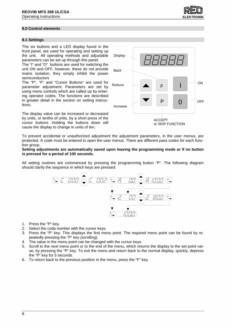
8.0 Control elements
8.1 Settings
The six buttons and a LED display found in the front panel, are used for operating and setting up the unit. All operating methods and adjustable parameters can be set up through this panel. The “I“ and “O“ buttons are used for switching the unit ON and OFF, however, these do not provide mains isolation, they simply inhibit the power semiconductors The “P“, “F“ and “Cursor Buttons“ are used for parameter adjustment. Parameters are set by using menu controls which are called up by enter-ing operator codes. The functions are described in greater detail in the section on setting instruc-tions. The display value can be increased or decreased by units, or tenths of units, by a short press of the cursor buttons. Holding the buttons down will cause the display to change in units of ten. To prevent accidental or unauthorized adjustment the adjustment parameters, in the user menus, are protected. A code must be entered to open the user menus. There are different pass codes for each func-tion group. Setting adjustments are automatically saved upon le aving the programming mode or if no button is pressed for a period of 100 seconds. All setting routines are commenced by pressing the programming button “P“. The following diagram should clarify the sequence in which keys are pressed:
1. Press the “P“ key. 2. Select the code number with the cursor keys. 3. Press the “P“ key. This displays the first menu point. The required menu point can be found by re-
peatedly pressing the “P“ key (scrolling). 4. The value in the menu point can be changed with the cursor keys. 5. Scroll to the next menu point or to the end of the menu, which returns the display to the set point val-
ue, by pressing the “P“ key. To exit the menu and return back to the normal display, quickly, depress the “P“ key for 5 seconds.
6. To return back to the previous position in the menu, press the “F“ key.
P P
P
P
P P

REOVIB MFS 268 UL/CSA Operating Instructions
9
ELEKTRONIK
9.0 Commissioning
9.1 Assembling position
Please fasten the devices on a vibration-free underground and take care for sufficient air circulation.
9.2 Preliminary steps
• Check that the unit is correct for the local mains supply (rating plate information) and that it is correct-ly rated for the feed system.
• Connect the controller according to the connection diagram • When applications with frequently on and off cycles are required, use the intended enable input. It is
prohibited to open the current circuit with a switch or a contactor while the feeder is running. 9.2.1 Important points
Using the control units described in this document, it is possible to adjust the feed system that it runs in resonance. In this condition it is possible to obtain excessive output for a very low set point setting. Therefore extreme care should be taken to avoid causing damage to the drive coil, through hammering.
In practice it is not possible to run at resonant frequency without accelerometer feedback because the system would be unstable and uncontrollable. The system must be set safely off resonance i.e. either above or below the natural frequency. Resonant frequency: Depending on the spring and mass design of the feeder system it is possible to have resonance at more than one frequency. These additional resonance points are multiples of the main frequency. For this reason in critical situations it is possible that the automatic frequency search will not find true resonance and in such cases the natural frequency must be determined manually. 9.2.1.1 Operating frequency of the feeder coil It is possible that the current flowing through the coil will increase for a small frequency adjustment. And so this should be checked with a true RMS instrument for each new application as well as monitoring the coil for heat build-up. The coil should be designed for the correct operating frequency to prevent excessive current draw and the consequential overloading of the coil. 9.2.1.2 Measurement of the output voltage and curre nt The voltage and current cannot be measured with a regular instrument because the controller output uses an electronic inverter with a pulse width modulation signal. An effective measuring instrument such as a moving iron meter (analog) must be used. It is recommended that an analog instrument is used rather than an electronic multi-meter which will give a misleading reading.
!
!
REOVIB MFS 268 UL/CSA Operating Instructions
10
ELEKTRONIK
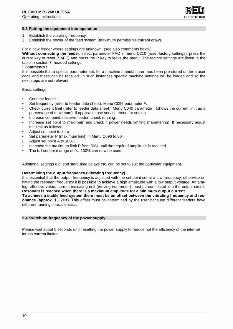
9.3 Putting the equipment into operation
1. Establish the vibrating frequency. 2. Establish the power of the feed system (maximum permissible current draw). For a new feeder where settings are unknown: (see also comments below) Without connecting the feeder , select parameter FAC in menu C210 (reset factory settings), press the cursor key to reset (SAFE) and press the P key to leave the menu. The factory settings are listed in the table in section 7, headed settings ! Comments ! It is possible that a special parameter set, for a machine manufacturer, has been pre-stored under a user code and these can be recalled. In such instances specific machine settings will be loaded and so the next steps are not relevant. Basic settings: • Connect feeder. • Set frequency (refer to feeder data sheet). Menu C096 parameter F. • Check current limit (refer to feeder data sheet). Menu C040 parameter I (shows the current limit as a
percentage of maximum). If applicable use service menu for setting. • Increase set point, observe feeder, check running. • Increase set point to maximum and check if power needs limiting (hammering). If necessary adjust
the limit as follows:- • Adjust set point to zero • Set parameter P (maximum limit) in Menu C096 to 50 • Adjust set point A to 100%. • Increase the maximum limit P from 50% until the required amplitude is reached. • The full set point range of 0…100% can now be used. Additional settings e.g. soft start, time delays etc. can be set to suit the particular equipment. Determining the output frequency (vibrating frequen cy) It is essential that the output frequency is adjusted with the set point set at a low frequency, otherwise on hitting the resonant frequency it is possible to achieve a high amplitude with a low output voltage. An ana-log, effective value, current indicating unit (moving iron meter) must be connected into the output circuit. Resonant is reached when there is a maximum amplitu de for a minimum output current. To achieve a stable feed system there must be an of fset between the vibrating frequency and res-onance (approx. 1…2Hz). This offset must be determined by the user because different feeders have different running characteristics. 9.4 Switch-on frequency of the power supply
Please wait about 5 seconds until resetting the power supply to reduce not the efficiency of the internal inrush current limiter.
REOVIB MFS 268 UL/CSA Operating Instructions
11
ELEKTRONIK
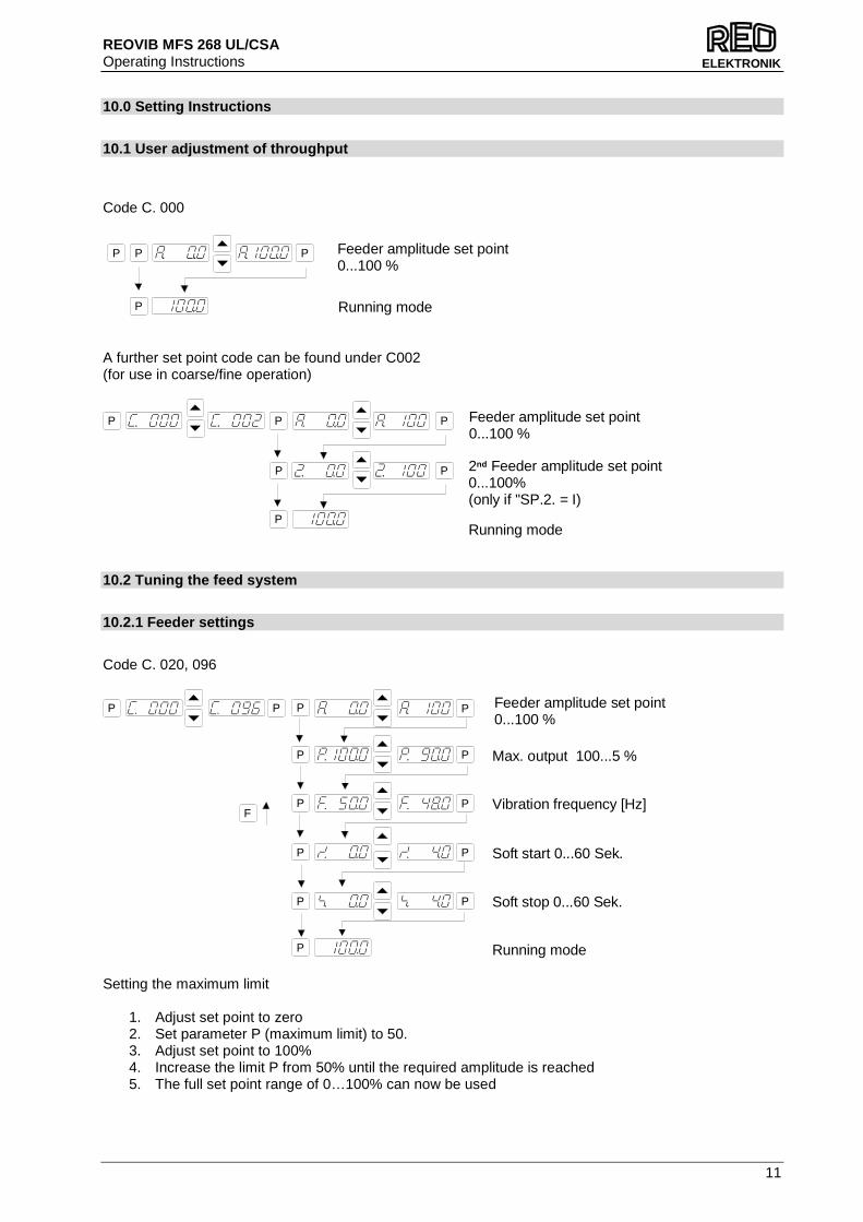
10.0 Setting Instructions
10.1 User adjustment of throughput
Code C. 000
A further set point code can be found under C002 (for use in coarse/fine operation)
10.2 Tuning the feed system
10.2.1 Feeder settings
Code C. 020, 096
P P
P
P
P
P
P
P
P
P
P
P
Soft start 0...60 Sek.
Soft stop 0...60 Sek.
Running mode
Vibration frequency [Hz]
Max. output 100...5 %
Feeder amplitude set point0...100 %
P
F
Setting the maximum limit
1. Adjust set point to zero 2. Set parameter P (maximum limit) to 50. 3. Adjust set point to 100% 4. Increase the limit P from 50% until the required amplitude is reached 5. The full set point range of 0…100% can now be used
Feeder amplitude set point0...100 %
Running mode
P P P
P
P P
P
P
P
P
Feeder amplitude set point0...100 %
2nd Feeder amplitude set point0...100%(only if "SP.2. = I)
Running mode

REOVIB MFS 268 UL/CSA Operating Instructions
12
ELEKTRONIK
10.2.2 Track control
10.2.3 Sensor time out
10.2.4 Set point source
Code C. 003
P P P
P
P
P
P
P
P
F
P
0 = Set point using display I = External set point
0 = External set point 0...+10 V / 0...20 mA I = External set point 4...20 mA
0 = Level sensor control I = 2nd set point active
0 = Enable I = Invert Enable
Running mode
0 = 0...10 V/ 0(4)...20 mAI = Potentiometer
POT is not available on 16A IP20 units
0 = Sensor time out not active I = Sensor time out active
E. = Sensor time out [sec.]
P P
P
Code C. 015
P
Running modeP
P Ai. = switch off time air valve 0...60 Sec.
On time delay 0...60 sec.
Off time delay 0...60 sec.
0 = No sensor inverting I = Sensor inverting
Code C. 167, 007
0 = Sensor time out not active I = Sensor time out active
E. = Sensor time out [sec.]
P P
P
P
P
P
P
P
P
P
F
Running modeP
REOVIB MFS 268 UL/CSA Operating Instructions
13
ELEKTRONIK
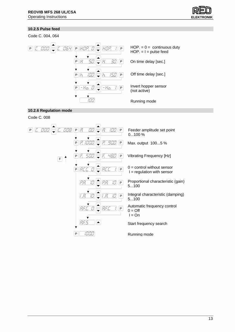
10.2.5 Pulse feed
Code C. 004, 064
10.2.6 Regulation mode
Code C. 008
Vibrating Frequency [Hz]
Max. output 100...5 %
P P
P
P
P
P
P
P
P
P
P
P
P
F
Feeder amplitude set point0...100 %
Proportional characteristic (gain)5...100
Start frequency search
Automatic frequency control0 = Off I = On
Integral characteristic (damping)5...100
0 = control without sensor I = regulation with sensor
Running mode
Off time delay [sec.]
Invert hopper sensor(not active)
Running mode
On time delay [sec.]
HOP. = 0 = continuous dutyHOP. = I = pulse feed
P
P
P
PP
P
P
P P

REOVIB MFS 268 UL/CSA Operating Instructions
14
ELEKTRONIK
10.2.6.1 Instructions for using regulation mode • An accelerometer e.g. SW 70 must be fitted to the vibratory feeder in order to run in regulation mode.
The accelerometer should have a frequency range corresponding to that of the feeder. • All vibration signals, that are picked up by the accelerometer, are used by the regulator circuit. Stray
signals generated by neighbouring machinery, a flimsy accelerometer mounting, or an unstable sup-port frame, can cause incorrect regulation to occur. It is especially important to ensure that there are no external influences, of this type, during the automatic frequency search routine.
• Resonant frequencies: It is possible to have several vibrating frequencies, where resonance occurs,
depending on the springing and masses of the system. The additional resonant points are at multi-ples of the dominant resonant frequency. Under extreme circumstances the automatic frequency search may be unable to differentiate between these frequencies and so in theses instances the fre-quency must be set manually.
10.2.6.2 Mounting the accelerometer
The accelerometer should generate signals for the movement and acceleration of the feeder, which are fed back to the regulator circuit of the control unit. Therefore it is very important that no other extraneous vibration signals are picked up by the sensor
The sensor should be positioned, that it moves in the same direction as the feeder, ideally in the same plane as the springs. It should be fitted on a solid block that will not generate vibration signals.
The sensor cable need to be fixed with a cable clam p to avoid damage of the cable.
SW SW
SW
100
100
cable clamp
REOVIB MFS 268 UL/CSA Operating Instructions
15
ELEKTRONIK
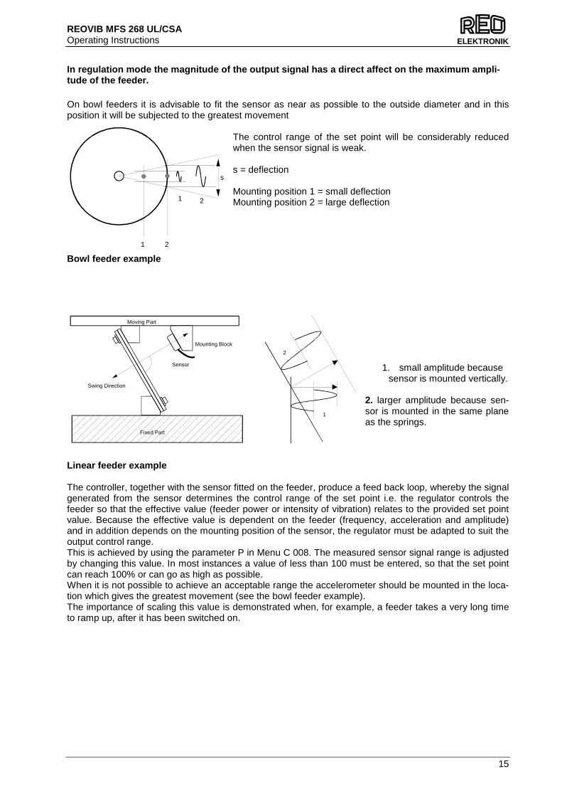
In regulation mode the magnitude of the output sign al has a direct affect on the maximum ampli-tude of the feeder. On bowl feeders it is advisable to fit the sensor as near as possible to the outside diameter and in this position it will be subjected to the greatest movement
The control range of the set point will be considerably reduced when the sensor signal is weak. s = deflection Mounting position 1 = small deflection Mounting position 2 = large deflection
Bowl feeder example
1. small amplitude because sensor is mounted vertically. 2. larger amplitude because sen-sor is mounted in the same plane as the springs.
Linear feeder example The controller, together with the sensor fitted on the feeder, produce a feed back loop, whereby the signal generated from the sensor determines the control range of the set point i.e. the regulator controls the feeder so that the effective value (feeder power or intensity of vibration) relates to the provided set point value. Because the effective value is dependent on the feeder (frequency, acceleration and amplitude) and in addition depends on the mounting position of the sensor, the regulator must be adapted to suit the output control range. This is achieved by using the parameter P in Menu C 008. The measured sensor signal range is adjusted by changing this value. In most instances a value of less than 100 must be entered, so that the set point can reach 100% or can go as high as possible. When it is not possible to achieve an acceptable range the accelerometer should be mounted in the loca-tion which gives the greatest movement (see the bowl feeder example). The importance of scaling this value is demonstrated when, for example, a feeder takes a very long time to ramp up, after it has been switched on.
1 2
21
s
Sensor
Swing Direction
Mounting Block
Moving Part
Fixed Part
1
2
REOVIB MFS 268 UL/CSA Operating Instructions
16
ELEKTRONIK
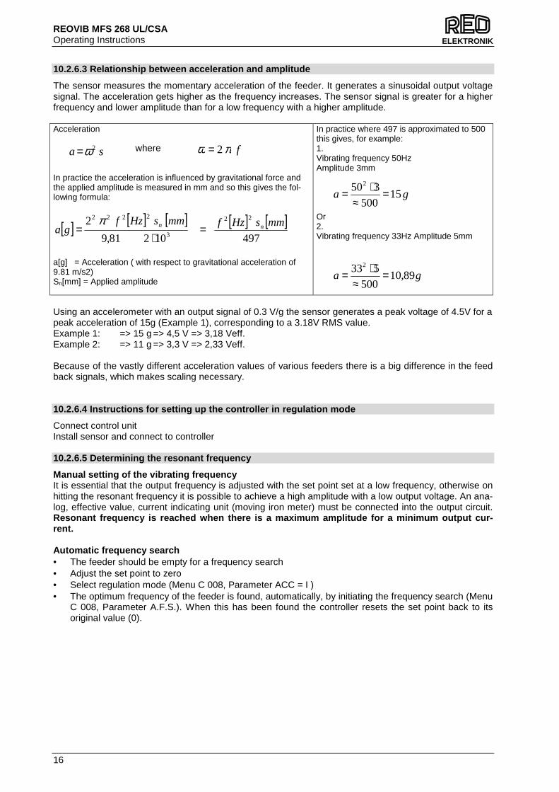
10.2.6.3 Relationship between acceleration and ampl itude
The sensor measures the momentary acceleration of the feeder. It generates a sinusoidal output voltage signal. The acceleration gets higher as the frequency increases. The sensor signal is greater for a higher frequency and lower amplitude than for a low frequency with a higher amplitude. Acceleration In practice the acceleration is influenced by gravitational force and the applied amplitude is measured in mm and so this gives the fol-lowing formula:
[ ] [ ] [ ] [ ] [ ]49710281,9
2 22
3
2222mmsHzfmmsHzf
ga nn =⋅
=π
a[g] = Acceleration ( with respect to gravitational acceleration of 9.81 m/s2) Sn[mm] = Applied amplitude
In practice where 497 is approximated to 500 this gives, for example: 1. Vibrating frequency 50Hz Amplitude 3mm Or 2. Vibrating frequency 33Hz Amplitude 5mm
Using an accelerometer with an output signal of 0.3 V/g the sensor generates a peak voltage of 4.5V for a peak acceleration of 15g (Example 1), corresponding to a 3.18V RMS value. Example 1: => 15 g => 4,5 V => 3,18 Veff. Example 2: => 11 g => 3,3 V => 2,33 Veff. Because of the vastly different acceleration values of various feeders there is a big difference in the feed back signals, which makes scaling necessary. 10.2.6.4 Instructions for setting up the controller in regulation mode
Connect control unit Install sensor and connect to controller 10.2.6.5 Determining the resonant frequency
Manual setting of the vibrating frequency It is essential that the output frequency is adjusted with the set point set at a low frequency, otherwise on hitting the resonant frequency it is possible to achieve a high amplitude with a low output voltage. An ana-log, effective value, current indicating unit (moving iron meter) must be connected into the output circuit. Resonant frequency is reached when there is a maxim um amplitude for a minimum output cur-rent. Automatic frequency search • The feeder should be empty for a frequency search • Adjust the set point to zero • Select regulation mode (Menu C 008, Parameter ACC = I ) • The optimum frequency of the feeder is found, automatically, by initiating the frequency search (Menu
C 008, Parameter A.F.S.). When this has been found the controller resets the set point back to its original value (0).
fπω 2=sa 2ω=
ga 15500
3502
=≈
⋅=
where
ga 89,10500
5332
=≈
⋅=
REOVIB MFS 268 UL/CSA Operating Instructions
17
ELEKTRONIK
10.2.6.6 Optimisating controller in regulation mode
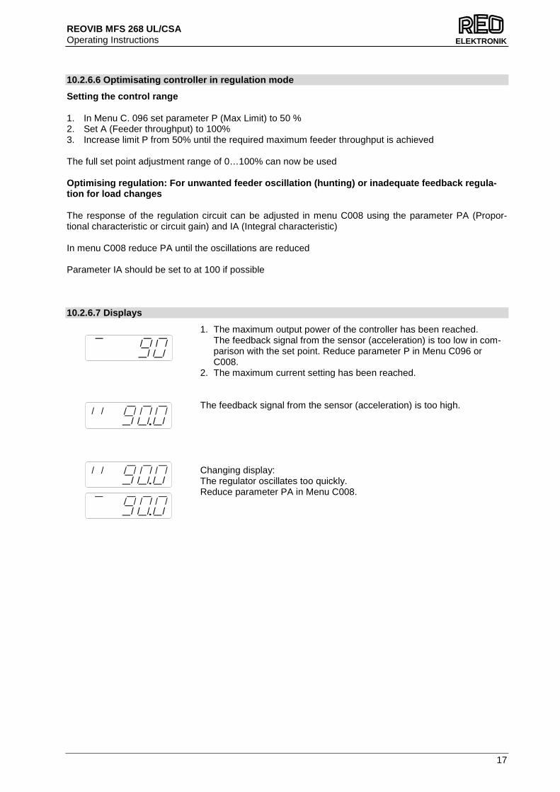
Setting the control range 1. In Menu C. 096 set parameter P (Max Limit) to 50 % 2. Set A (Feeder throughput) to 100% 3. Increase limit P from 50% until the required maximum feeder throughput is achieved The full set point adjustment range of 0…100% can now be used Optimising regulation: For unwanted feeder oscillat ion (hunting) or inadequate feedback regula-tion for load changes The response of the regulation circuit can be adjusted in menu C008 using the parameter PA (Propor-tional characteristic or circuit gain) and IA (Integral characteristic) In menu C008 reduce PA until the oscillations are reduced Parameter IA should be set to at 100 if possible 10.2.6.7 Displays
1. The maximum output power of the controller has been reached. The feedback signal from the sensor (acceleration) is too low in com-parison with the set point. Reduce parameter P in Menu C096 or C008.
2. The maximum current setting has been reached.
The feedback signal from the sensor (acceleration) is too high.
Changing display: The regulator oscillates too quickly. Reduce parameter PA in Menu C008.
REOVIB MFS 268 UL/CSA Operating Instructions
18
ELEKTRONIK
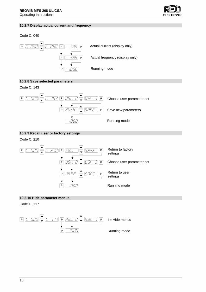
10.2.7 Display actual current and frequency
Code C. 040
10.2.8 Save selected parameters
Code C. 143
10.2.9 Recall user or factory settings
Code C. 210
10.2.10 Hide parameter menus
Code C. 117
Running mode
P P
P
P Actual current (display only)
P P Actual frequency (display only)
I = Hide menus
Running mode
P P
P
P
Save new parameters
Running mode
P P
P P
P Choose user parameter set
Return to factorysettings
Return to usersettings
Running mode
P P
P
P
P
P
P P Choose user parameter set

REOVIB MFS 268 UL/CSA Operating Instructions
19
ELEKTRONIK
11.0 Error messages / ERROR reset
Errors are indicated by an alternating code and ERROR display Overload limit Output level exceeded e.g. incorrect frequency setting, coil air-gap to wide. Short circuit trip Faulty coil, short circuit or defective cable.. Over voltage Supply voltage too high or back EMF from the coil at lower fre-quencies. Current spike limit Frequency set too low for installed coil or frequency altered too rapidly during setting up. Sensor fault (only when regulation mode is selected) Accelerometer not working or faulty. ERROR Reset through Menu C009 Sensor time out After sensor time out has elapsed ERROR Reset is achieved by pressing touch panel key s 0 or I during normal operation or by using Menu C009. In the event of an error check that this is not caused by incorrect wiring or cable faults. The error mes-sage, ERROR ACC, can also occur if regulation mode is chosen (in Menu C008) and an accelerometer is not connected, for example. Reset the error in the following manner: ERROR RESET
Frequently appearing Errors, which are not describe d in this chapter, should be reported to the manufacturer.
P P
Clear Error
REOVIB MFS 268 UL/CSA Operating Instructions
20
ELEKTRONIK
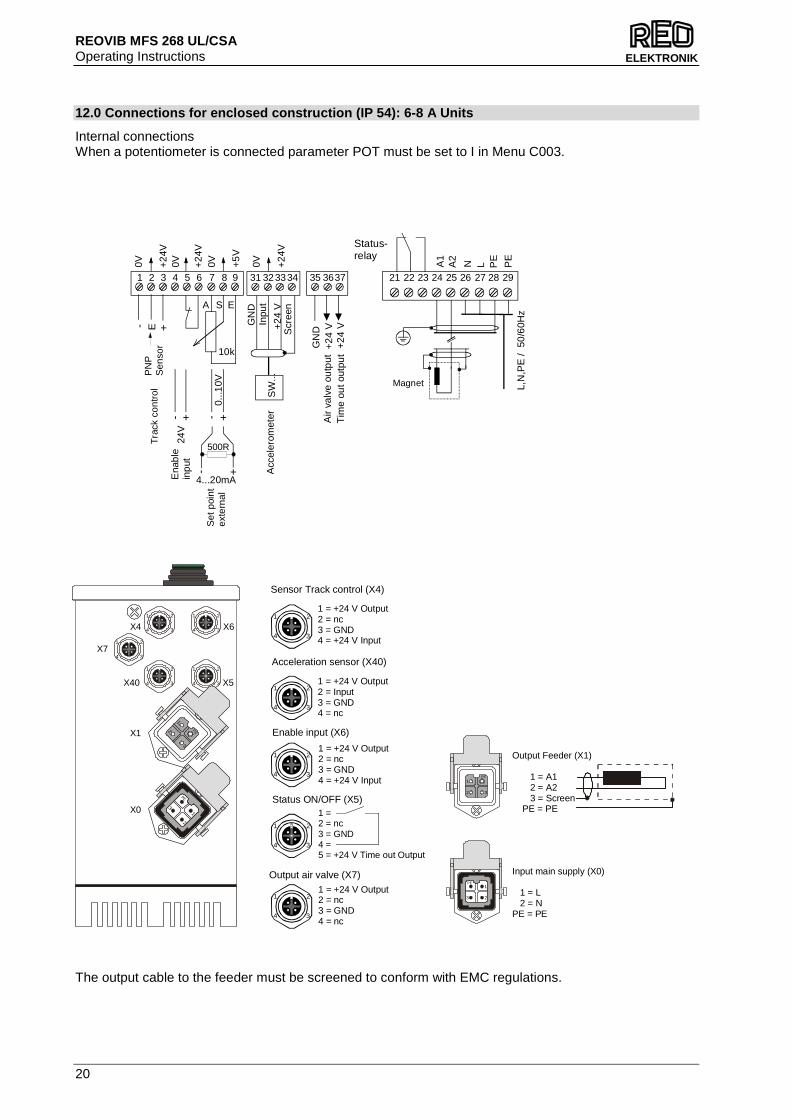
12.0 Connections for enclosed construction (IP 54): 6-8 A Units
Internal connections When a potentiometer is connected parameter POT must be set to I in Menu C003. The output cable to the feeder must be screened to conform with EMC regulations.
34 25 26 2721 22 23 24 28 29
LA2
A1
N PE
PE
L,N
,PE
/ 5
0/6
0Hz
4...20mA+-
0...1
0V
+-
24V
5 6 71 2 3 4 8 9
E
ESA
10k
500R
+
+
-
-
+2
4V
+5
V
+2
4 V
SW
...
31 3233 35 3637
GN
D+
24
V+
24
V
0V 0V 0V
GN
DStatus-relay
PN
PS
enso
r
Air
valv
e ou
tput
Tim
e ou
t out
put
Inpu
t
Magnet
Scr
een
+2
4V
0V +2
4V
Tra
ck c
ontr
ol
Ena
ble
inp
ut
Acc
eler
omet
er
Set
poi
ntex
tern
al
1 2
34
5
1 2
34
1 2
34
1 2
34
1 2
34
1
PE2
3
1
PE
2
3
X4
X5
X6
X40
X7
X1
X0
1 = +24 V Output2 = Input3 = GND4 = nc
1 = +24 V Output2 = nc3 = GND4 = +24 V Input
Acceleration sensor (X40)
Sensor Track control (X4)
Enable input (X6)
Status ON/OFF (X5)
Output air valve (X7)
1 = +24 V Output2 = nc3 = GND4 = +24 V Input
1 = +24 V Output2 = nc3 = GND4 = nc
1 = 2 = nc3 = GND4 = 5 = +24 V Time out Output
1 2
34
1 2
34
1 2
34
1 2
34
1 2
34
5
1PE
2 3
Input main supply (X0)
1 = L 2 = NPE = PE
1PE
23
Output Feeder (X1)
1 = A1 2 = A2 3 = Screen PE = PE
REOVIB MFS 268 UL/CSA Operating Instructions
21
ELEKTRONIK
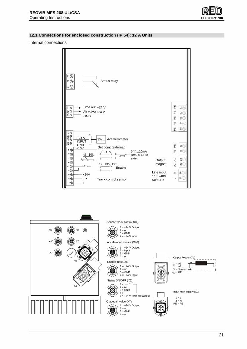
12.1 Connections for enclosed construction (IP 54): 12 A Units
Internal connections
Track control sensor
Enable
Set point (external)
GND+24 V+24 V
Air valveTime out
Status relay
Line input110/240V50/60Hz
Outputmagnet
Accelerometer
56
71
23
48
9
E+24V
E
S
A
10k0...10V 0(4)...20mA+ +
-
-
7
8
7
8 R=500 OHMextern
+10V
12...24V, DC+
-
45
21
22
23
55
54
535
25
12
72
62
92
82
52
4
INPUTGND
+24 V SW...
3132
3334
3536
37
L
NA
2 A
1P
E
PE
PE
P
E
PE
P
E
PE
-
X4
X7
X40
X6
X5
X0
X1
1
4
5
67
8
23
1 2
34
1 2
34
1 2
34
1 2
34
5
1 2
341
PE
2
3
1 = +24 V Output2 = Input3 = GND4 = nc
1 = +24 V Output2 = nc3 = GND4 = +24 V Input
Acceleration sensor (X40)
Sensor Track control (X4)
Enable input (X6)
Status ON/OFF (X5)
Output air valve (X7)
1 = +24 V Output2 = nc3 = GND4 = +24 V Input
1 = +24 V Output2 = nc3 = GND4 = nc
1 = 2 = nc3 = GND4 = 5 = +24 V Time out Output
3 2 1
Output Feeder (X1)
1 = A12 = A23 = Screen = PE
1PE
23
Input main supply (X0)
1 = L 2 = NPE = PE
1 2
34
1 2
34
1 2
34
1 2
34
1 2
34
5
REOVIB MFS 268 UL/CSA Operating Instructions
22
ELEKTRONIK
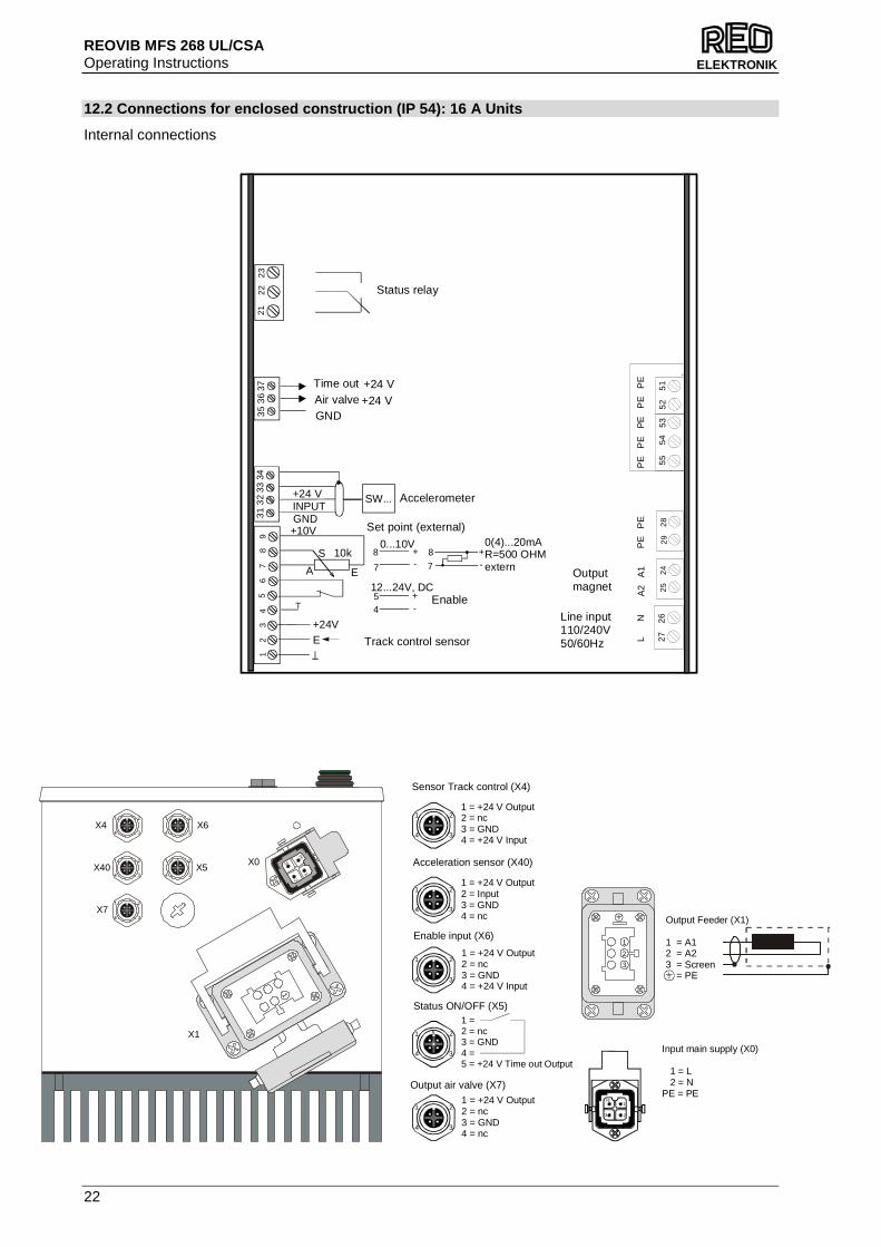
12.2 Connections for enclosed construction (IP 54): 16 A Units
Internal connections
Track control sensor
Enable
Set point (external)
GND+24 V+24 V
Air valveTime out
Status relay
Line input110/240V50/60Hz
Outputmagnet
Accelerometer
56
71
23
48
9
E+24V
E
S
A
10k0...10V 0(4)...20mA+ +
-
-
7
8
7
8 R=500 OHMextern
+10V
12...24V, DC+
-
45
21
22
23
55
54
535
25
12
72
62
92
82
52
4
INPUTGND
+24 V SW...
3132
3334
3536
37
L
NA
2 A
1P
E
PE
PE
P
E
PE
P
E
PE
-
1PE
2
31
1 = +24 V Output2 = Input3 = GND4 = nc
1 = +24 V Output2 = nc3 = GND4 = +24 V Input
Acceleration sensor (X40)
Sensor Track control (X4)
Enable input (X6)
Status ON/OFF (X5)
Output air valve (X7)
1 = +24 V Output2 = nc3 = GND4 = +24 V Input
1 = +24 V Output2 = nc3 = GND4 = nc
1 = 2 = nc3 = GND4 = 5 = +24 V Time out Output
Output Feeder (X1)
1 = A12 = A23 = Screen = PE
1PE
23
Input main supply (X0)
1 = L 2 = NPE = PE
1 2
34
1 2
34
1 2
34
1 2
34
1 2
34
5
X4
X7
X40
X6
X5X0
X1
1
2
3

REOVIB MFS 268 UL/CSA Operating Instructions
23
ELEKTRONIK
13.0 Connections for panel mounting construction (I P 20): 3 A, 6 A, 8 A
The output cable to the feeder must be screened to conform with EMC regulations. When a potentiometer is connected parameter POT mus t be set to I in Menu C003.
Spring-clamp for screen connec-tion of output and accelerometer cables. EMC- screen clamp (accessories)
REOVIB MFS268
F I
0P
E
+24V
E
S
A
10k
Material-Sensor
0...10V0(4)...20mA
++
- -7
8
7
8
R=500 OHMExternal
+5V
12...24V, DC
+
- 4
5
INPUT
GND
+ 24VSW...
L, N, PE 115V/ / 230V, 50/60Hz
L
N
PE
PE
Magnet
*
Enable
Set point
Accelerometer
internal Relay
Mains
black
orange
red
Screen
REOVIB MFS 268 UL/CSA Operating Instructions
24
ELEKTRONIK
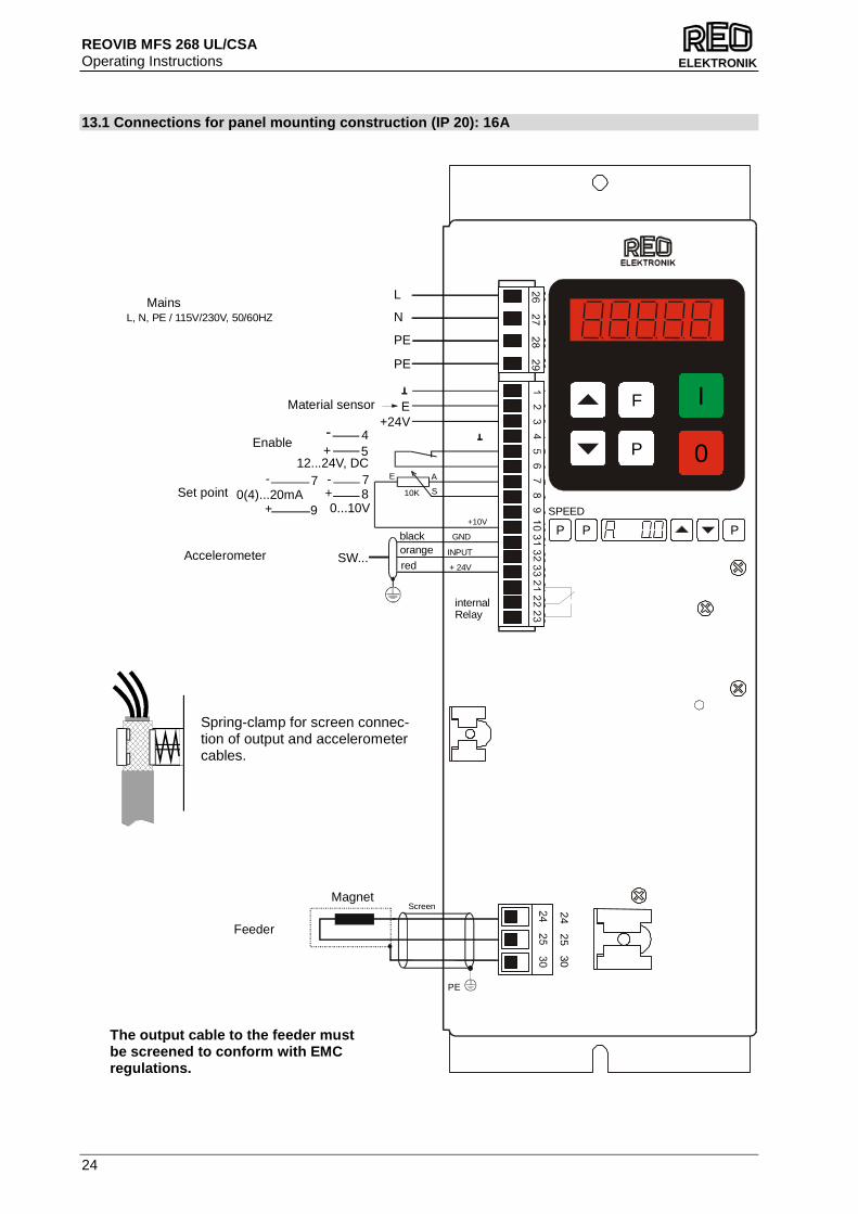
13.1 Connections for panel mounting construction (I P 20): 16A
Spring-clamp for screen connec-tion of output and accelerometer cables.
The output cable to the feeder must be screened to conform with EMC regulations.
P
F I
0
SPEED
P P P
26 27 28 29
10 31 32 33 21 22 23
12
34
56
78
9
24 25 30
E+24V
Material sensor
Enable
line choke
Feeder
Set point 0(4)...20mA+
- 7
9
E
S
A
10K
0...10V+- 7
8
+10V
12...24V, DC
45
INPUT
GND
+ 24VAccelerometer SW...
black
L
N
PE
MagnetScreen
internal Relay
MainsL, N, PE / 115V/230V, 50/60HZ
PE
+
orange
red
PE
REOVIB MFS 268 UL/CSA Operating Instructions
25
ELEKTRONIK
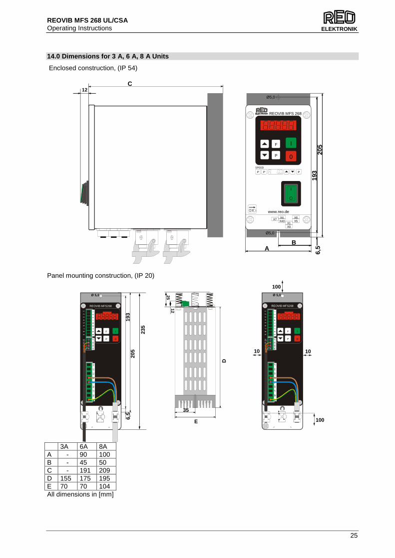
14.0 Dimensions for 3 A, 6 A, 8 A Units
Enclosed construction, (IP 54)
Panel mounting construction, (IP 20)
3A 6A 8A A - 90 100 B - 45 50 C - 191 209 D 155 175 195 E 70 70 104 All dimensions in [mm]
35Ø 5,0
Ø 5,0
21 22 23 24 25 26 27
28 291 2 3
4 5 6
7 8 9
31 32 33 34
REOVIB MFS268
F I
0P
235
Ø 5,0
Ø 5,0
21 22 23 24 25 26 27
28 291
2 3 4 5 6
7 8
931
32 33 34
REOVIB MFS268
F I
0P
100
10 10
100
D12
25
205
193
6,5
E
12C
SPEED
P P P
REOVIB MFS 268
X1
X4X7
X6
X0
X40 X5
P
F I
0
www.reo.de
Ø5,0
Ø5,0
AB
205
193
6,5
REOVIB MFS 268 UL/CSA Operating Instructions
26
ELEKTRONIK
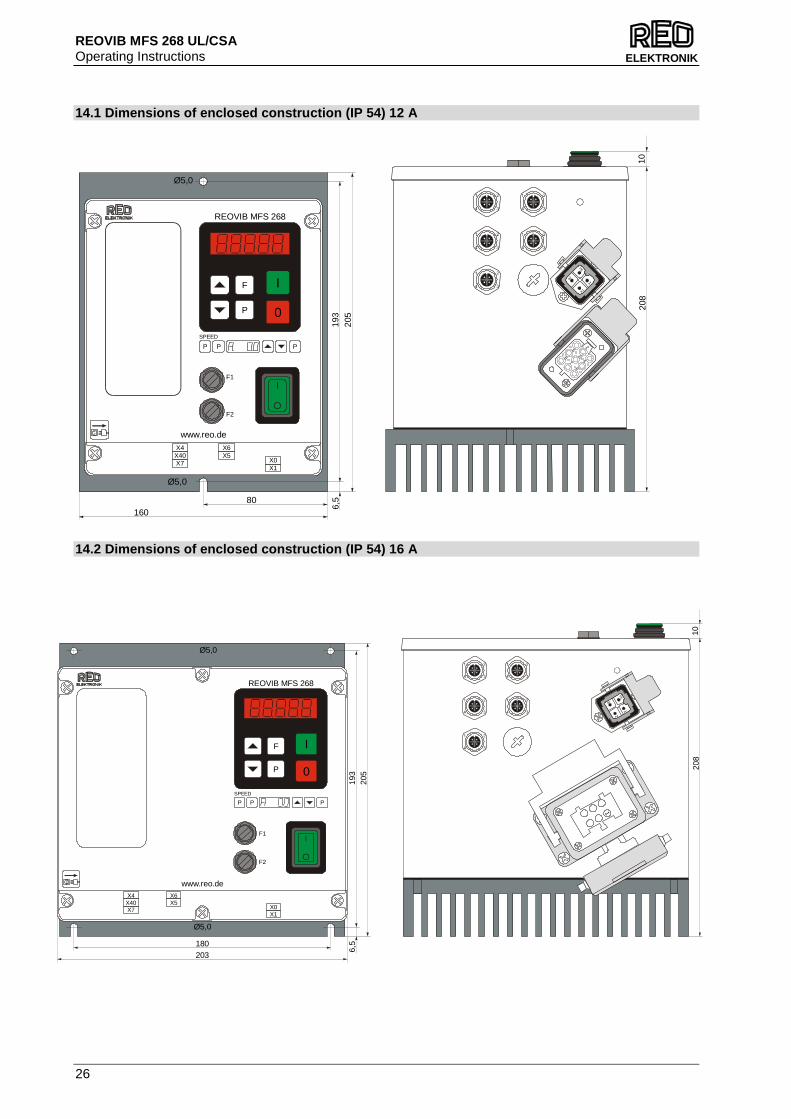
14.1 Dimensions of enclosed construction (IP 54) 12 A
14.2 Dimensions of enclosed construction (IP 54) 16 A
P
F I
0
X1X0
REOVIB MFS 268
SPEED
P P P
F1
F2
X6X5
X4X40X7
www.reo.de
Ø5,0
Ø5,0
6,5
205
193
16080
1
PE
2
3
1
4
5
67
8
23
208
10
REOVIB MFS 268
SPEED
P P P
X6X5
X4X40X7
X1X0
F1
F2
www.reo.de
P
F I
0
6,5
205
193
Ø5,0
Ø5,0
203180
1P
E
2
31
208
10
REOVIB MFS 268 UL/CSA Operating Instructions
27
ELEKTRONIK
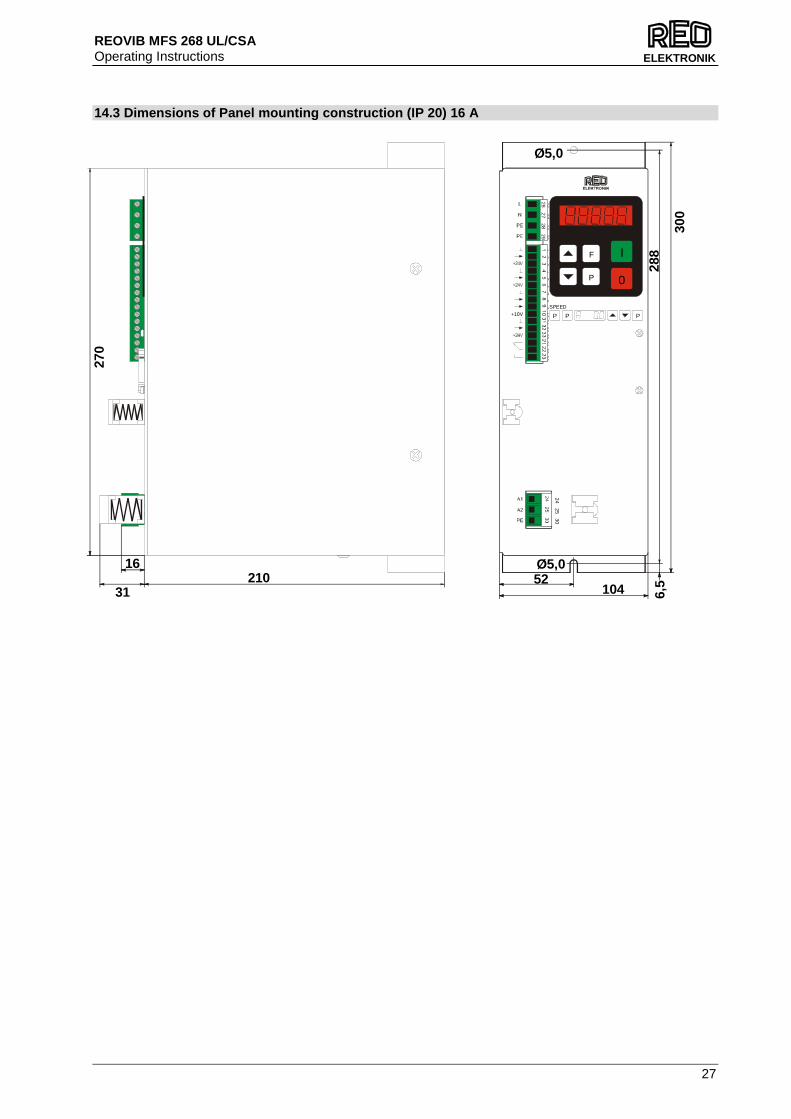
14.3 Dimensions of Panel mounting construction (IP 20) 16 A
P
F I
0
26 27 28 29
+10V
10 31 32 33 21 22 23
12
34
56
78
9 SPEED
P P P
24 25 30
Ø5,0
Ø5,052
104210
31
16
6,5
270
288
300

REOVIB MFS 268 UL/CSA Operating Instructions
28
ELEKTRONIK
A 1.0 Service appendix
ATTENTION ! The settings described in this section relating to the service menu are intended for use by skilled persons because the functions and limits of the fee d system can be greatly influenced by their adjustment It is the responsibility of the supplier of the equ ipment to decide whether this information should be released or restricted for use by service engine ers only. The service menu cannot be accessed through the normal menu structure. It can only be enabled by using a special key code. Service Menu The critical parameters, current limit and user adjustable frequency range are held in a separate service menu. This menu cannot be reached through the normal menu structure and must be enabled by using an additional code number. This prevents the unauthorised changing of these sensitive parameters
• Current Limit – Protects the coil against overload. The output current limit is set to the maximum current rating of the coil.
• Frequency limits – Protection against unhealthy operation. The vibrating frequency limits available to the user are fixed.
• Output voltage limit 100 V The output voltage limit allows 110v coils to be used on a 230V supply without damage.
Parameter: Display Factory
setting: Entry c ode:
• Enable service menu 0 / I En.S: 0 127 • Adjust current limit 0...100 % I. 100 040 • Set lower frequency 5...300 Hz F.L. 35 040 • Set upper frequency 6...300 Hz F.H. 140 040 • Limit output voltage 100 V 0 / I P.Li. 0 040
REOVIB MFS 268 UL/CSA Operating Instructions
29
ELEKTRONIK
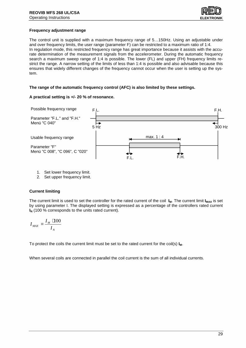
Frequency adjustment range The control unit is supplied with a maximum frequency range of 5…150Hz. Using an adjustable under and over frequency limits, the user range (parameter F) can be restricted to a maximum ratio of 1:4. In regulation mode, this restricted frequency range has great importance because it assists with the accu-rate determination of the measurement signals from the accelerometer. During the automatic frequency search a maximum sweep range of 1:4 is possible. The lower (FL) and upper (FH) frequency limits re-strict the range. A narrow setting of the limits of less than 1:4 is possible and also advisable because this ensures that widely different changes of the frequency cannot occur when the user is setting up the sys-tem. The range of the automatic frequency control (AFC) is also limited by these settings. A practical setting is +/- 20 % of resonance.
1. Set lower frequency limit. 2. Set upper frequency limit.
Current limiting The current limit is used to set the controller for the rated current of the coil IM. The current limit IMAX is set by using parameter I. The displayed setting is expressed as a percentage of the controllers rated current IN (100 % corresponds to the units rated current).
To protect the coils the current limit must be set to the rated current for the coil(s) IM. When several coils are connected in parallel the coil current is the sum of all individual currents.
N
MMAX I
II
100⋅=
5 Hz 300 Hz
F.L. F.H.
F.L. F.H.
max. 1 : 4
Possible frequency range
Parameter "F.L." and "F.H."Menü "C 040"
Usable frequency range
Parameter "F"Menü "C 008", "C 096", C "020"
REOVIB MFS 268 UL/CSA Operating Instructions
30
ELEKTRONIK
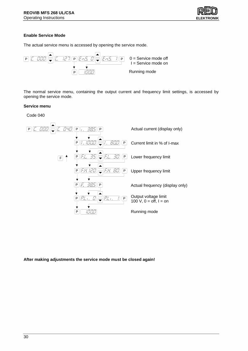
Enable Service Mode The actual service menu is accessed by opening the service mode.
The normal service menu, containing the output current and frequency limit settings, is accessed by opening the service mode. Service menu
After making adjustments the service mode must be c losed again!
0 = Service mode off I = Service mode on
P P
P
P
Running mode
Code 040
Upper frequency limit
Running mode
P P
P
P
P
P
P
P
P
P
Lower frequency limit
Current limit in % of I-max
Actual current (display only)
F
P P Actual frequency (display only)
Output voltage limit100 V, 0 = off, I = on
P P
REOVIB MFS 268 UL/CSA Operating Instructions
31
ELEKTRONIK
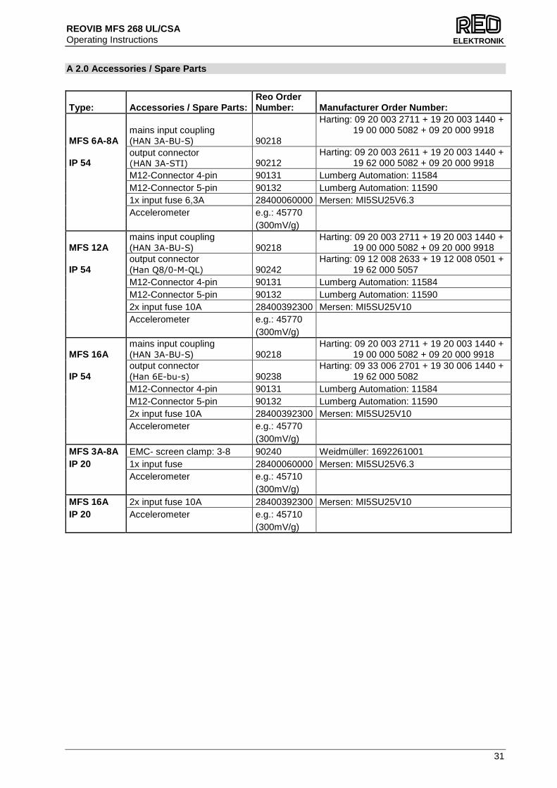
A 2.0 Accessories / Spare Parts
Type: Accessories / Spare Parts: Reo Order Number: Manufacturer Order Number:
MFS 6A-8A mains input coupling (HAN 3A-BU-S) 90218
Harting: 09 20 003 2711 + 19 20 003 1440 + 19 00 000 5082 + 09 20 000 9918
IP 54 output connector (HAN 3A-STI) 90212
Harting: 09 20 003 2611 + 19 20 003 1440 + 19 62 000 5082 + 09 20 000 9918
M12-Connector 4-pin 90131 Lumberg Automation: 11584 M12-Connector 5-pin 90132 Lumberg Automation: 11590 1x input fuse 6,3A 28400060000 Mersen: MI5SU25V6.3 Accelerometer e.g.: 45770 (300mV/g)
MFS 12A mains input coupling (HAN 3A-BU-S) 90218
Harting: 09 20 003 2711 + 19 20 003 1440 + 19 00 000 5082 + 09 20 000 9918
IP 54 output connector (Han Q8/0-M-QL) 90242
Harting: 09 12 008 2633 + 19 12 008 0501 + 19 62 000 5057
M12-Connector 4-pin 90131 Lumberg Automation: 11584 M12-Connector 5-pin 90132 Lumberg Automation: 11590 2x input fuse 10A 28400392300 Mersen: MI5SU25V10 Accelerometer e.g.: 45770 (300mV/g)
MFS 16A mains input coupling (HAN 3A-BU-S) 90218
Harting: 09 20 003 2711 + 19 20 003 1440 + 19 00 000 5082 + 09 20 000 9918
IP 54 output connector (Han 6E-bu-s) 90238
Harting: 09 33 006 2701 + 19 30 006 1440 + 19 62 000 5082
M12-Connector 4-pin 90131 Lumberg Automation: 11584 M12-Connector 5-pin 90132 Lumberg Automation: 11590 2x input fuse 10A 28400392300 Mersen: MI5SU25V10 Accelerometer e.g.: 45770 (300mV/g) MFS 3A-8A EMC- screen clamp: 3-8 90240 Weidmüller: 1692261001 IP 20 1x input fuse 28400060000 Mersen: MI5SU25V6.3 Accelerometer e.g.: 45710 (300mV/g) MFS 16A 2x input fuse 10A 28400392300 Mersen: MI5SU25V10 IP 20 Accelerometer e.g.: 45710 (300mV/g)

REOVIB MFS 268 UL/CSA Operating Instructions
32
ELEKTRONIK
Headquarters - Germany REO ELEKTRONIK AG Brühler Straße 100 · D-42657 Solingen Tel.: +49 (0)212 8804 0 · Fax: +49 (0)212 8804 188 REO INDUCTIVE COMPONENTS AG Brühler Straße 100 · D-42657 Solingen Tel.: +49 (0)212 8804 0 · Fax: +49 (0)212 8804 188 E-Mail: [email protected] Internet: www.reo.de
China REO Shanghai Inductive Components Co., Ltd No. 536 ShangFeng Road · Pudong, 201201 Shanghai · China Tel.: +86 (0)21 5858 0686 · Fax: +86 (0)21 5858 0289 E-Mail: [email protected] · Internet: www.reo.cn
France REO VARIAC S.A.R.L. ZAC Du Clos aux Pois 1 · 6/8 rue de la Closerie-LISSES· F-91048 Evry Cédex Tel.: +33 (0)1 6911 1898 · Fax: +33 (0)1 6911 0918 E-Mail: [email protected] · Internet: www.reo.fr
Great Britain REO (UK) Ltd. Units 2-4 Callow Hill Road · Craven Arms · Shropshire SY7 8NT · UK Tel.: +44 (0)1588 673 411 · Fax: +44 (0)1588 672 718 E-Mail: [email protected] · Internet: www.reo.co.uk
India REO GPD INDUCTIVE COMPONENTS PVT. LTD 2/202 Luna Road · Village Luna · Taluka Padra Vadodara - 391440 · India Tel.: +91 (2662) 221723 E-Mail: [email protected] · Internet: www.reo-ag.in
Italy REO ITALIA S.r.l. Via Treponti, 29 · I-25086 Rezzato (BS) Tel.: +39 030 279 3883 · Fax: +39 030 279 0600 E-Mail: [email protected] · Internet: www.reoitalia.it
Poland REO CROMA Sp.zo.o ul. Pozaryskiego 28, bud 20 · PL-04-703 Warszawa Tel.: +48 (0)22 812 3066 · Fax: +48 (0)22 815 6906 E-Mail: [email protected] · Internet: www.croma.com.pl
Spain REO ESPAÑA 2002 S.A. C/Manuel Ventura i Campeny 21B · local 9 · E-08339 Vilassar de Dalt (Barcelona) Tel.: +34 937 509 994 · Fax: +34 937 509 995 E-Mail: [email protected] · Internet: www.reospain.com
Switzerland REO ELEKTRONIK AG Im Halbiacker 5a · CH-8352 Elsau Tel.: +41 (0)52 363 2820 · Fax: +41 (0)52 363 1241 E-Mail: [email protected] · Internet: www.reo.ch
Turkey REOTURKEY ELEKTRONİK San. ve Tic. Ltd. Şti. Halil Rıfatpasa Mah. · Darülceze CD Perpa Tic Merkezi B Blok Kat 8 No:1095 · TR-34384 Sisli – Istanbul Tel.: +90 (0)212 2215 118 · Fax: +90 (0)212 2215 119 E-Mail: [email protected] · Internet: www.reo-turkey.com
USA REO-USA, Inc. 8450 E. 47th St · USA-Indianapolis, IN 46226 Tel.: +1 317 8991 395 · Fax: +1 317 8991 396 E-Mail: [email protected] · Internet: www.reo-usa.com
Divisions - Germany REO INDUCTIVE COMPONENTS AG
TrainTechnologies Division Centre of Competence Berlin Erasmusstraße 14 · D-10553 Berlin Tel.: +49 (0)30 3670236t 0 · Fax: +49 (0)30 3670236 10 E-Mail: [email protected] · Internet: www.reo.de Fertigung /Production TrainTechnologies Division Eduard-Maurer-Straße 13 · D-16761 Hennigsdorf
IBK Drives Division Holzhausener Straße 52 · D-16866 Kyritz Tel.: +49 (0)33971 485 0 · Fax: +49 (0)33971 485 90 E-Mail: [email protected] · Internet: www.reo.de
Setzermann Medical Division Schuldholzinger Weg 7 · D-84347 Pfarrkirchen Tel.: +49 (0)8561 9886 0 · Fax: +49 (0)8561 9886 40 E-Mail: [email protected] · Internet: www.reo.de
Test and PowerQuality Division Brühler Straße 100 · D-42657 Solingen Tel.: +49 (0)212 8804 0 · Fax: +49 (0)212 8804 188 E-Mail: [email protected] · Internet: www.reo.de