2695 separations module operator's guide
TRANSCRIPT
Waters 2695Separations Module
Operator’s Guide
34 Maple StreetMilford, MA 01757
71500269502, Revision B

NOTICE
The information in this document is subject to change without notice and should not be construed as a commitment by Waters Corporation. Waters Corporation assumes no responsibility for any errors that may appear in this document. This document is believed to be complete and accurate at the time of publication. In no event shall Waters Corporation be liable for incidental or consequential damages in connection with, or arising from, the use of this document.
© 2001–2002 WATERS CORPORATION. PRINTED IN THE UNITED STATES OF AMERICA. ALL RIGHTS RESERVED. THIS DOCUMENT OR PARTS THEREOF MAY NOT BE REPRODUCED IN ANY FORM WITHOUT THE WRITTEN PERMISSION OF THE PUBLISHER.
Alliance, Millennium, PIC, and Waters are registared trademarks, and LAC/E, PerformancePLUS, SAT/IN, SCC, and Synchronized Composition Control are trademarks of Waters Corporation.
Micromass is a registered trademark, and MassLynx and MassLynx NT are trademarks of Micromass Ltd.
All other trademarks or registered trademarks are the sole property of their respective owners.

Note: When you use the instrument, follow generally accepted procedures for quality control and methods development.
If you observe a change in the retention of a particular compound, in the resolution between two compounds, or in peak shape, immediately determine the reason for the changes. Until you determine the cause of a change, do not rely on the separation results.
Note: The Installation Category (Overvoltage Category) for this instrument is Level II. The Level II Category pertains to equipment that receives its electrical power from a local level, such as an electrical wall outlet.
STOPAtención: Changes or modifications to this unit not expressly approved by the party responsible for compliance could void the user’s authority to operate the equipment.
Important : Toute modification sur cette unité n’ayant pas été expressément approuvée par l’autorité responsable de la conformité à la réglementation peut annuler le droit de l’utilisateur à exploiter l’équipement.
Achtung: Jedwede Änderungen oder Modifikationen an dem Gerät ohne die ausdrückliche Genehmigung der für die ordnungsgemäße Funktionstüchtigkeit verantwortlichen Personen kann zum Entzug der Bedienungsbefugnis des Systems führen.
Avvertenza: eventuali modifiche o alterazioni apportate a questa unità e non espressamente approvate da un ente responsabile per la conformità annulleranno l’autorità dell’utente ad operare l’apparecchiatura.
Atención: cualquier cambio o modificación efectuado en esta unidad que no haya sido expresamente aprobado por la parte responsable del cumplimiento puede anular la autorización del usuario para utilizar el equipo.
Caution: Use caution when working with any polymer tubing under pressure:
• Always wear eye protection when near pressurized polymer tubing.
• Extinguish all nearby flames.
• Do not use Tefzel tubing that has been severely stressed or kinked.
• Do not use Tefzel tubing with tetrahydrofuran (THF) or concentrated nitric or sulfuric acids.
• Be aware that methylene chloride and dimethyl sulfoxide cause Tefzel tubing to swell, which greatly reduces the rupture pressure of the tubing.
Attention : Soyez très prudent en travaillant avec des tuyaux de polymères sous pression :
• Portez toujours des lunettes de protection quand vous vous trouvez à proximité de tuyaux de polymères.
• Eteignez toutes les flammes se trouvant à proximité.
• N'utilisez pas de tuyau de Tefzel fortement abîmé ou déformé.
• N'utilisez pas de tuyau de Tefzel avec de l'acide sulfurique ou nitrique, ou du tétrahydrofurane (THF).
• Sachez que le chlorure de méthylène et le sulfoxyde de diméthyle peuvent provoquer le gonflement des tuyaux de Tefzel, diminuant ainsi fortement leur pression de rupture.
Vorsicht: Bei der Arbeit mit Polymerschläuchen unter Druck ist besondere Vorsicht angebracht:
• In der Nähe von unter Druck stehenden Polymerschläuchen stets Schutzbrille tragen.
• Alle offenen Flammen in der Nähe löschen.
• Keine Tefzel-Schläuche verwenden, die stark geknickt oder überbeansprucht sind.
• Tefzel-Schläuche nicht für Tetrahydrofuran (THF) oder konzentrierte Salpeter- oder Schwefelsäure verwenden.
• Durch Methylenchlorid und Dimethylsulfoxid können Tefzel-Schläuche quellen; dadurch wird der Berstdruck des Schlauches erheblich reduziert.
Precauzione: prestare attenzione durante le operazioni con i tubi di polimero sotto pressione:
• Indossare sempre occhiali da lavoro protettivi nei pressi di tubi di polimero pressurizzati.
• Estinguere ogni fonte di ignizione circostante.
• Non utilizzare tubi Tefzel soggetti a sollecitazioni eccessive o incurvati.
• Non utilizzare tubi Tefzel contenenti tetraidrofurano (THF) o acido solforico o nitrico concentrato.
• Tenere presente che il cloruro di metilene e il dimetilsolfossido provocano rigonfiamento nei tubi Tefzel, che riducono notevolmente il limite di pressione di rottura dei tubi stessi.
Advertencia: manipular con precaución los tubos de polímero bajo presión:
• Protegerse siempre los ojos en las proximidades de tubos de polímero bajo presión.
• Apagar todas las llamas que estén a proximidad.
• No utilizar tubos Tefzel que hayan sufrido tensiones extremas o hayan sido doblados.
• No utilizar tubos Tefzel con tetrahidrofurano (THF) o ácidos nítrico o sulfúrico concentrados.
• No olvidar que el cloruro de metileno y el óxido de azufre dimetilo dilatan los tubos Tefzel, lo que reduce en gran medida la presión de ruptura de los tubos.
Caution: The user shall be made aware that if the equipment is used in a manner not specified by the manufacturer, the protection provided by the equipment may be impaired.
Attention : L’utilisateur doit être informé que si le matériel est utilisé d’une façon non spécifiée par le fabricant, la protection assurée par le matériel risque d’être défectueuses.
Vorsicht: Der Benutzer wird darauf aufmerksam gemacht, dass bei unsachgemäßer Verwenddung des Gerätes unter Umständen nicht ordnungsgemäß funktionieren.
Precauzione: l’utente deve essere al corrente del fatto che, se l’apparecchiatura viene usta in un modo specificato dal produttore, la protezione fornita dall’apparecchiatura potrà essere invalidata.
Advertencia: el usuario deberá saber que si el equipo se utiliza de forma distinta a la especificada por el fabricante, las medidas de protección del equipo podrían ser insuficientes.
Caution: To protect against fire hazard, replace fuses with those of the same type and rating.
Attention : Remplacez toujours les fusibles par d’autres du même type et de la même puissance afin d’éviter tout risque d’incendie.
Vorsicht: Zum Schutz gegen Feuergefahr die Sicherungen nur mit Sicherungen des gleichen Typs und Nennwertes ersetzen.
Precauzione: per una buona protezione contro i rischi di incendio, sostituire i fusibili con altri dello stesso tipo e amperaggio.
Advertencia: sustituya los fusibles por otros del mismo tipo y características para evitar el riesgo de incendio.

Caution: To avoid possible electrical shock, disconnect the power cord before servicing the instrument.
Attention : Afin d’éviter toute possibilité de commotion électrique, débranchez le cordon d’alimentation de la prise avant d’effectuer la maintenance de l’instrument.
Vorsicht: Zur Vermeidung von Stromschlägen sollte das Gerät vor der Wartung vom Netz getrennt werden.
Precauzione: per evitare il rischio di scossa elettrica, scollegare il cavo di alimentazione prima di svolgere la manutenzione dello strumento.
Precaución: para evitar descargas eléctricas, desenchufe el cable de alimentación del instrumento antes de realizar cualquier reparación.
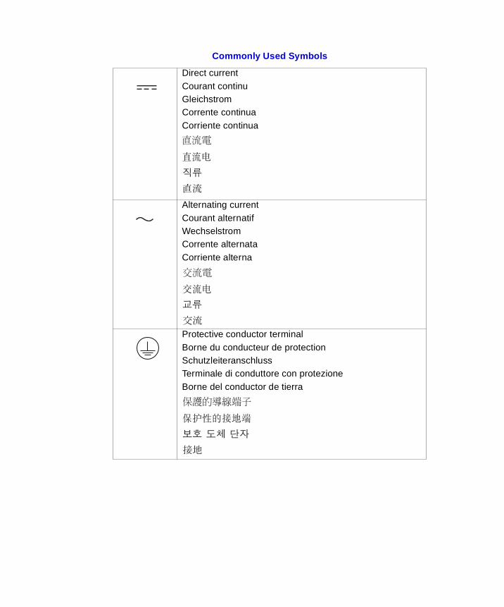
Commonly Used Symbols
Direct currentCourant continuGleichstromCorrente continuaCorriente continua
Alternating currentCourant alternatifWechselstromCorrente alternataCorriente alterna
Protective conductor terminalBorne du conducteur de protectionSchutzleiteranschlussTerminale di conduttore con protezioneBorne del conductor de tierra
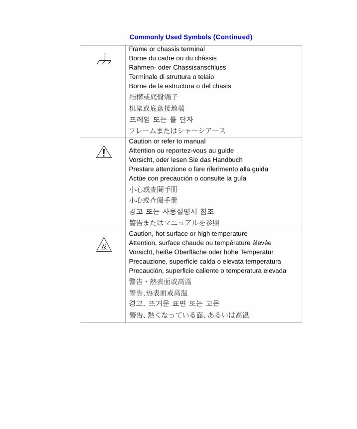
Frame or chassis terminalBorne du cadre ou du châssisRahmen- oder ChassisanschlussTerminale di struttura o telaioBorne de la estructura o del chasis
Caution or refer to manualAttention ou reportez-vous au guideVorsicht, oder lesen Sie das HandbuchPrestare attenzione o fare riferimento alla guidaActúe con precaución o consulte la guía
Caution, hot surface or high temperatureAttention, surface chaude ou température élevéeVorsicht, heiße Oberfläche oder hohe TemperaturPrecauzione, superficie calda o elevata temperaturaPrecaución, superficie caliente o temperatura elevada
Commonly Used Symbols (Continued)
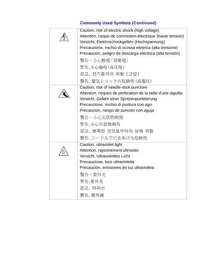
Caution, risk of electric shock (high voltage)Attention, risque de commotion électrique (haute tension)Vorsicht, Elektroschockgefahr (Hochspannung)Precauzione, rischio di scossa elettrica (alta tensione)Precaución, peligro de descarga eléctrica (alta tensión)
Caution, risk of needle-stick punctureAttention, risques de perforation de la taille d’une aiguilleVorsicht, Gefahr einer SpritzenpunktierungPrecauzione, rischio di puntura con agoPrecaución, riesgo de punción con aguja
Caution, ultraviolet lightAttention, rayonnement ultrvioletVorsicht, Ultraviolettes LichtPrecauzione, luce ultraviolettaPrecaución, emisiones de luz ultravioleta
Commonly Used Symbols (Continued)
UV
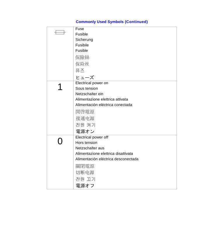
FuseFusibleSicherungFusibileFusible
Electrical power onSous tensionNetzschalter einAlimentazione elettrica attivataAlimentación eléctrica conectada
Electrical power offHors tensionNetzschalter ausAlimentazione elettrica disattivataAlimentación eléctrica desconectada
Commonly Used Symbols (Continued)
1
0
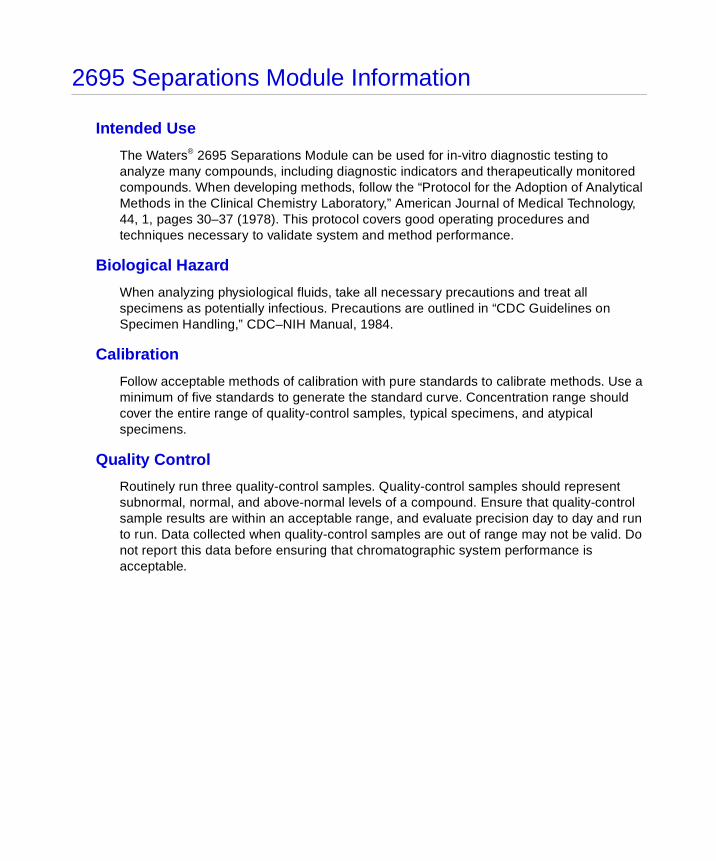
2695 Separations Module Information
Intended Use
The Waters® 2695 Separations Module can be used for in-vitro diagnostic testing to analyze many compounds, including diagnostic indicators and therapeutically monitored compounds. When developing methods, follow the “Protocol for the Adoption of Analytical Methods in the Clinical Chemistry Laboratory,” American Journal of Medical Technology, 44, 1, pages 30–37 (1978). This protocol covers good operating procedures and techniques necessary to validate system and method performance.
Biological Hazard
When analyzing physiological fluids, take all necessary precautions and treat all specimens as potentially infectious. Precautions are outlined in “CDC Guidelines on Specimen Handling,” CDC–NIH Manual, 1984.
Calibration
Follow acceptable methods of calibration with pure standards to calibrate methods. Use a minimum of five standards to generate the standard curve. Concentration range should cover the entire range of quality-control samples, typical specimens, and atypical specimens.
Quality Control
Routinely run three quality-control samples. Quality-control samples should represent subnormal, normal, and above-normal levels of a compound. Ensure that quality-control sample results are within an acceptable range, and evaluate precision day to day and run to run. Data collected when quality-control samples are out of range may not be valid. Do not report this data before ensuring that chromatographic system performance is acceptable.
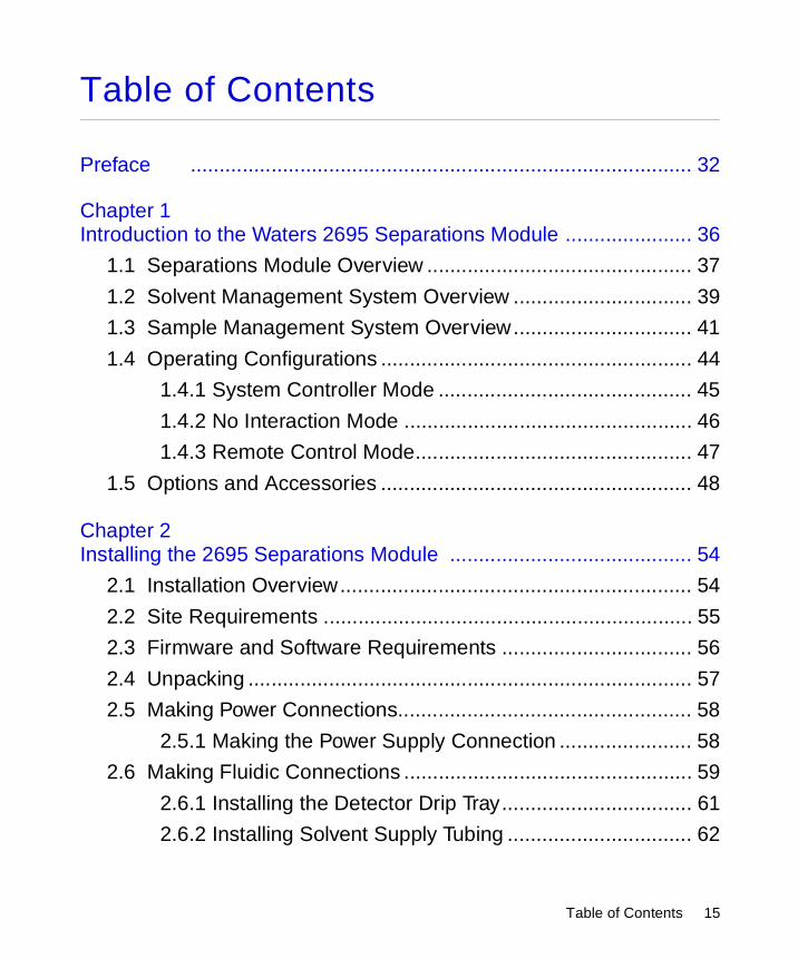
Table of Contents
Preface ....................................................................................... 32
Chapter 1 Introduction to the Waters 2695 Separations Module ...................... 36
1.1 Separations Module Overview .............................................. 37
1.2 Solvent Management System Overview ............................... 39
1.3 Sample Management System Overview............................... 41
1.4 Operating Configurations ...................................................... 44
1.4.1 System Controller Mode ............................................ 45
1.4.2 No Interaction Mode .................................................. 46
1.4.3 Remote Control Mode................................................ 47
1.5 Options and Accessories ...................................................... 48
Chapter 2 Installing the 2695 Separations Module .......................................... 54
2.1 Installation Overview............................................................. 54
2.2 Site Requirements ................................................................ 55
2.3 Firmware and Software Requirements ................................. 56
2.4 Unpacking ............................................................................. 57
2.5 Making Power Connections................................................... 58
2.5.1 Making the Power Supply Connection ....................... 58
2.6 Making Fluidic Connections .................................................. 59
2.6.1 Installing the Detector Drip Tray................................. 61
2.6.2 Installing Solvent Supply Tubing ................................ 62
Table of Contents 15
2.6.3 Making Sparge Gas Connections .............................. 62
2.6.4 Installing the Degasser Vent Tubing........................... 64
2.6.5 Making Waste Line Connections ............................... 65
2.6.6 Installing Needle Wash and Plunger Seal Wash Reservoirs ................................................................. 66
2.6.7 Connecting the Column ............................................. 67
2.6.8 Connecting the Column-Selection Valve.................... 68
2.6.9 Connecting the Detector ............................................ 71
2.7 Signal Connections ............................................................... 72
2.7.1 I/O Signal Connections .............................................. 73
2.7.2 Digital Signal Connections......................................... 77
2.8 Adding Hardware Options..................................................... 78
2.8.1 Installing an Optional Sample Loop ........................... 79
2.8.2 Installing the Column Heater ..................................... 81
2.8.3 Installing a Syringe .................................................... 81
Chapter 3 Preparing the 2695 Separations Module for Operation ................... 82
3.1 Operating Overview .............................................................. 83
3.1.1 Screen Display Overview........................................... 83
3.1.2 Using the Keypad....................................................... 85
3.2 Configuring the Separations Module..................................... 90
3.2.1 Setting Configuration Parameters.............................. 91
3.2.2 Configuring the Operating Mode.............................. 100
3.3 Preparing the Solvent Management System ...................... 105
3.3.1 Preparing Solvent Reservoirs .................................. 106
Table of Contents 16
3.3.2 Degassing Solvents ................................................. 106
3.3.3 Priming the Plunger Seal-Wash Pump .................... 107
3.3.4 Priming the Solvent Management System............... 109
3.4 Preparing the Sample Management System ...................... 109
3.4.1 Purging the Sample Management System .............. 109
3.4.2 Priming the Needle-Wash Pump ............................. 110
3.4.3 Adjusting the Seal Pack ........................................... 112
3.4.4 Loading Carousels................................................... 112
3.5 Recommended Procedures for Preparing for Operation..... 113
3.5.1 AutoStartPLUS Startup Procedure .......................... 119
3.6 Powering Off the Separations Module................................. 133
Chapter 4 Front Panel Control ........................................................................ 135
4.1 Routine Startup................................................................... 135
4.2 Loading Sample Vials ......................................................... 136
4.3 Monitoring Your HPLC System............................................ 137
4.4 Performing Direct Functions................................................ 141
4.4.1 Performing a Dry Prime ........................................... 143
4.4.2 Performing a Wet Prime........................................... 145
4.4.3 Purging the 2410 and 410 Reference Cell............... 148
4.4.4 Programming the Sparge Cycles............................. 149
4.4.5 Equilibrating the System .......................................... 150
4.4.6 Conditioning the Column ......................................... 151
4.4.7 Injecting Samples .................................................... 152
Table of Contents 17
Chapter 5 Making Automatic Runs ................................................................. 154
5.1 Making Automatic Runs in Stand-Alone Mode.................... 155
5.1.1 Running a Sample Set............................................. 156
5.1.2 Viewing Sample Sets............................................... 158
5.1.3 Making a Run from a Sample Template................... 159
5.1.4 Modifying a Sample Set During a Run .................... 160
5.1.5 Stopping a Run ........................................................ 161
5.2 Making Automatic Runs Under Millennium Control............. 162
5.3 Making Automatic Runs Under Micromass MassLynx Control ................................................................................ 163
Chapter 6 Creating Methods, Sample Sets, and Sample Templates ............. 165
6.1 Creating and Editing Separation Methods .......................... 166
6.1.1 Creating a Separation Method................................. 167
6.1.2 Editing a Separation Method ................................... 168
6.1.3 Copying and Editing a Separation Method .............. 169
6.1.4 Locking and Unlocking a Separation Method .......... 169
6.2 Setting Separation Method Parameters .............................. 170
6.2.1 Setting Mobile Phase Screen Parameter Values ..... 170
6.2.2 Setting Sample Parameter Values ........................... 176
6.2.3 Setting Autosampler Parameter Values ................... 178
6.2.4 Setting Column Parameter Values........................... 179
6.2.5 Setting I/O Parameter Values .................................. 181
6.2.6 Setting Detector Parameters.................................... 185
Table of Contents 18

6.3 Creating and Editing a Sample Set..................................... 191
6.3.1 Functions ................................................................. 193
6.3.2 Linking Rows in a Sample Set ................................. 195
6.4 Creating a Sample Template............................................... 196
6.5 Using the Disk Drive ........................................................... 197
Chapter 7 Maintenance .................................................................................. 200
7.1 Maintenance Considerations .............................................. 200
7.2 Maintaining the Solvent Management System.................... 202
7.2.1 Overview ................................................................. 202
7.2.2 Removing the Head, Seal-Wash Assembly, and Plunger ............................................................. 204
7.2.3 Replacing the Plunger Seals .................................. 205
7.2.4 Replacing the Seal-Wash Assembly Seals.............. 208
7.2.5 Cleaning and Replacing a Plunger ......................... 210
7.2.6 Replacing an Inlet Check Valve Cartridge ............... 211
7.2.7 Replacing the Inline Filter ....................................... 213
7.3 Maintaining the Sample Management System ................... 215
7.3.1 Overview ................................................................. 215
7.3.2 Replacing the Lower Needle-Wash Frit ................... 217
7.3.3 Replacing the Syringe ............................................. 219
7.3.4 Replacing the Needle and Seal Pack ...................... 223
7.3.5 Cleaning the Sample Compartment ........................ 228
7.4 Updating the Software Version Using the Floppy Disk Drive ........................................................................... 230
Table of Contents 19
Chapter 8 Diagnostics and Troubleshooting ................................................... 231
8.1 Safety and Handling............................................................ 231
8.2 Using the Error Log ............................................................ 232
8.3 Performing Main Diagnostics .............................................. 233
8.3.1 Priming the Plunger Seal Wash Pump .................... 235
8.3.2 Performing the Compression Check ....................... 236
8.3.3 Priming the Needle Wash Pump ............................. 238
8.3.4 Adjusting the Seals .................................................. 238
8.3.5 Service Utilities Diagnostics ................................... 241
8.4 Performing Other Diagnostics ............................................. 241
8.4.1 Performing the Motors and Valves Diagnostic ........ 243
8.4.2 Performing the Sensors Diagnostic ........................ 246
8.4.3 Performing the Static Leak Test .............................. 247
8.4.4 Performing the Valve Leak Test ............................... 250
8.4.5 Performing the Head Removal and Replacement Utility........................................................................ 251
8.4.6 Performing the Inputs and Outputs Diagnostic ....... 252
8.4.7 Performing the Keypad Diagnostic .......................... 253
8.4.8 Performing the Display Diagnostic ........................... 254
8.4.9 Performing the Carousel Test ................................. 254
8.4.10 Performing the Inline Degasser Test ..................... 255
8.4.11 Performing the Sample Heater/Cooler Test .......... 256
8.4.12 Performing the Defrost Sample Heater/Cooler Procedure ........................................ 257
8.4.13 Performing the Column Heater Test ...................... 258
Table of Contents 20
8.4.14 Rebuilding the Injector Valves ............................... 259
8.4.15 Turning Off the Gradient Proportioning Valve (GPV) ...................................................................... 260
8.4.16 Creating a GPV Test Method ................................. 261
8.4.17 Viewing the Firmware Checksum .......................... 262
8.5 Troubleshooting................................................................... 262
8.5.1 General Troubleshooting Hints................................. 263
8.5.2 Troubleshooting Chromatography Problems ........... 264
8.5.3 Troubleshooting Hardware Problems ...................... 269
Appendix A Specifications ................................................................................. 276
Appendix B Spare Parts..................................................................................... 282
B.1 Solvent Management System Spare Parts ........................ 282
B.2 Sample Management System Spare Parts ....................... 283
B.3 Separations Module Spare Parts ....................................... 284
B.4 Vials and Low Volume Inserts ........................................... 285
Appendix C Solvent Considerations................................................................... 287
C.1 Introduction ........................................................................ 287
C.2 Solvent Compatibility ......................................................... 288
C.3 Solvent Miscibility .............................................................. 291
C.4 Buffered Solvents .............................................................. 293
C.5 Head Height ...................................................................... 293
C.6 Solvent Viscosity ............................................................... 293
Table of Contents 21

C.7 Mobile Phase Solvent Degassing ...................................... 294
C.8 Wavelength Selection ........................................................ 296
Index ..................................................................................... 300
Table of Contents 22
List of Figures
1-1 Waters 2695 XE Separations Module (Front View) ....................... 361-2 Fluidic Path Through the Solvent Management System................ 391-3 Fluidic Path Through the Sample Management System................ 421-4 Syringe Assembly .......................................................................... 441-5 Digital Signal Control of an HPLC System..................................... 451-6 I/O Signal Control of an HPLC System.......................................... 461-7 Typical 2695 Separations Module HPLC System Under
Millennium Chromatography Manager Control .............................. 471-8 2695 Column Heater with 3-Column Selection Valve Installed...... 52
2-1 Steps to Install the Separations Module ........................................ 542-2 Typical System Dimensions ........................................................... 562-3 Rear Panel of the 2695 Separations Module ................................. 592-4 Steps to Making Fluidic Connections............................................. 602-5 Fluidic Connections in the Separations Module............................. 612-6 Installing Sparge Lines in a Solvent Reservoir .............................. 642-7 Side View of Frame Openings for Fluidic Connections
(Side Panel Removed)................................................................... 682-8 Three-Column Selection Valve Configuration (As Shipped) .......... 692-9 Six-Column Selection Valve Connections (Example) .................... 702-10 Column Regeneration Valve Connections (Example).................... 712-11 Step to Making Signal Connections............................................... 732-12 I/O Signal Connectors.................................................................... 742-13 Disconnecting the Sample Loop.................................................... 80
3-1 Diagnostic Test Results Screen ..................................................... 823-2 Main Screen................................................................................... 833-3 Alphabetic Screen Keys................................................................. 883-4 Steps for Entering Alphabetic Data................................................ 89
List of Figures 23
3-5 Configuration Screen ..................................................................... 903-6 Auto-Shutdown Dialog Box ............................................................ 933-7 Events In Dialog Box...................................................................... 943-8 Report Options Dialog Box ............................................................ 953-9 Sample Report............................................................................... 973-10 Compression Check Dialog Box .................................................... 993-11 Configuring the Operating Mode.................................................. 1003-12 Preparing the Solvent Management System for Operation ......... 1053-13 Status Screen .............................................................................. 1073-14 Diagnostics Screen...................................................................... 1083-15 Preparing the Sample Management System for Operation ......... 1093-16 Door is Open Dialog Box ............................................................. 1133-17 Preparing a New or Dry Separations Module for Operation
(Sparge-Based Unit) .................................................................... 1143-18 Preparing a New or Dry Separations Module for Operation
(PerformancePLUS Degasser-Based Unit) ................................. 1153-19 Preparing an Idle or Powered-Off Separations Module for
Operation (Sparge-Based Unit) ................................................... 1163-20 Preparing an Idle or Powered-Off Separations Module for
Operation (PerformancePLUS Degasser-Based Unit)................. 1173-21 Changing from a Buffered Solvent to an Organic Solvent
(Sparge-Based Unit) .................................................................... 1183-22 Changing from a Buffered Solvent to an Organic Solvent
(PerformancePLUS Degasser-Based Unit................................... 1193-23 AutoStartPLUS Main Screen ....................................................... 1203-24 Methods Screen with AutoStartPLUS Selected........................... 1213-25 AutoStartPLUS in Relation to a Common Startup Routine.......... 1233-26 Sample Set AutoStartPLUS......................................................... 1263-27 Separation Method Auto APLUS ................................................. 1263-28 Separation Method Auto BPLUS ................................................. 1273-29 Separation Method Auto CPLUS ................................................. 1283-30 Separation Method Auto DPLUS ................................................. 1293-31 Separation Method Auto Eq DegasPLUS.................................... 130
List of Figures 24
3-32 Separation Method Auto A:B GradPLUS..................................... 1313-33 Separation Method Auto Eq ColumnPLUS.................................. 1323-34 Separation Method Auto Purge LoopPLUS ................................. 133
4-1 Main Screen................................................................................. 1354-2 Door is Open Dialog Box ............................................................. 1364-3 First Page of Status Screen......................................................... 1384-4 Second Page of Status Screen.................................................... 1384-5 Sample Set Queue ...................................................................... 1394-6 Steps to Setting Up a Direct Control Run .................................... 1414-7 Direct Functions Menu................................................................. 1424-8 Prime/Vent Valve with Syringe ..................................................... 1444-9 Dry Prime Dialog Box .................................................................. 1444-10 Wet Prime Dialog Box.................................................................. 1464-11 Purge Injector Dialog Box ............................................................ 1484-12 Purge 410 Reference Dialog Box ................................................ 1494-13 Programmed Sparge Dialog Box ................................................. 1504-14 Equilibrate Dialog Box ................................................................. 1514-15 Condition Column Dialog Box...................................................... 1524-16 Inject Samples Dialog Box........................................................... 153
5-1 Main Screen................................................................................. 1545-2 Making an Automatic Run in Stand-Alone Mode ......................... 1555-3 Run Samples Screen................................................................... 1565-4 Run Samples Screen – Functional View ..................................... 1575-5 Run Samples Screen with Solvents Required Dialog Box........... 1585-6 Sample Set Screen – Injection View............................................ 1595-7 Sample Set Screen – Loading View ............................................ 1595-8 Setup Dialog Box ......................................................................... 160
6-1 Steps in Creating or Editing a Separation Method....................... 1676-2 Methods Screen........................................................................... 168
List of Figures 25

6-3 Mobile Phase Screen................................................................... 1706-4 Gradient Screen........................................................................... 1756-5 Sample Screen ............................................................................ 1776-6 Autosampler Screen .................................................................... 1786-7 Column Screen ............................................................................ 1806-8 I/O Screen.................................................................................... 1826-9 I/O Events Table........................................................................... 1836-10 Detectors Screen ......................................................................... 1856-11 Detector Selection Example ........................................................ 1856-12 2487(1) UV/Vis Detector Screen ................................................. 1876-13 486(1) UV/Vis Detector Screen ................................................... 1886-14 410 RI Detector Screen ............................................................... 1896-15 Detector Events Screen............................................................... 1906-16 Sample Set Screen...................................................................... 1926-17 Auto Standards Dialog Box.......................................................... 1946-18 Auto Add Dialog Box.................................................................... 1956-19 Linked Rows in a Sample Set...................................................... 1966-20 Methods Screen........................................................................... 1976-21 Export Methods Screen ............................................................... 1986-22 Import Methods Screen ............................................................... 199
7-1 Solvent Management System Components ................................ 2037-2 Solvent Management System Piston Chamber
Components (Exploded View) ..................................................... 2057-3 Plunger and Face Seal Orientation.............................................. 2077-4 Seal-Wash Assembly Seals......................................................... 2097-5 Plunger, Seal-Wash, and Head.................................................... 2117-6 Inlet Check Valve ......................................................................... 2127-7 Replacing the Inline Filter ............................................................ 2147-8 Sample Management System Components (Front View)............ 2167-9 Sample Management System Components (Right-Side View) ... 2167-10 Locating the Lower Frit Retainer.................................................. 218
List of Figures 26
7-11 Syringe Assembly Components................................................... 2207-12 Installing the Syringe ................................................................... 2217-13 Removing the Injector.................................................................. 2247-14 Removing the Seal Pack.............................................................. 2257-15 Replacing the Needle .................................................................. 2267-16 Aligning the Needle Port .............................................................. 2277-17 Accessing the Sample Compartment .......................................... 2297-18 Sample Compartment Components ............................................ 229
8-1 Error Log Screen ......................................................................... 2328-2 Printing the Error Log .................................................................. 2338-3 Diagnostics Screen...................................................................... 2348-4 Prime Seal Wash Screen............................................................. 2358-5 Compression Check Screen ........................................................ 2378-6 Prime Needle Wash Dialog Box................................................... 2388-7 Adjust Seals Screen .................................................................... 2398-8 Other Diagnostics Screen............................................................ 2418-9 Motors and Valves Diagnostic Screen ......................................... 2448-10 Sensor Diagnostic Screen ........................................................... 2468-11 Static Leak Test Screen ............................................................... 2488-12 Static Leak Test Results Screen .................................................. 2498-13 Valve Leak Test Screen ............................................................... 2518-14 Head Removal and Replacement Screen.................................... 2528-15 I/O Diagnostics Screen ................................................................ 2528-16 Keypad Diagnostic Screen........................................................... 2548-17 Carousel Test Screen .................................................................. 2558-18 Degasser Diagnostic Screen ....................................................... 2568-19 Sample Heater/Cooler Test Screen ............................................. 2578-20 Defrost Sample Heater/Cooler Screen ........................................ 2588-21 Column Heater Diagnostic Screen .............................................. 2598-22 Rebuilding the Injector Valves...................................................... 2608-23 Turn Off GPV Utility...................................................................... 261
List of Figures 27
8-24 GPV Test Separation Method ...................................................... 2618-25 Displaying the Firmware Checksum ............................................ 262
List of Figures 28
List of Tables
1-1 Alternate Stroke Volumes ............................................................. 41
1-1 Absolute Pressure Transducer Attributes ...................................... 501-2 Column Selection Valve Options ............................................. 51
2-1 Installation Site Requirements ...................................................... 552-2 Minimum Detector Firmware Requirements............................. 572-3 Minimum External Management System Software
Requirements ......................................................................... 572-4 Solvent Supply Tubing Identification ........................................ 622-5 Sparge Gas Line Identification ................................................ 632-6 Acceptable Contamination Limits for Helium Sparge Gas ........ 632-7 Needle Wash and Plunger Seal Wash Line Color Code........... 662-8 I/O Signals .............................................................................. 742-9 Chart Out Signal Conditions.................................................... 762-10 Event Switch Positions and Functions ..................................... 772-11 RS-232 Output Parameters Displayed in the Configuration
Screen ................................................................................... 77
3-1 Screen Keys in the Main Screen ................................................... 843-2 Keypad Functions ................................................................... 853-3 Screen Keys in the Configuration Screen ................................ 913-4 Compression Check Parameters ............................................. 993-5 Suggested Needle-Wash Solvents ........................................ 1113-6 Carousel Codes and Colors .................................................. 1123-7 AutoStartPLUS Run Times.................................................... 1213-8 Parameter Values.................................................................. 125
4-1 Status Screen Parameters .......................................................... 1394-2 Direct Functions .................................................................... 142
List of Tables 29
5-1 Icon in the Run Sample Screen .................................................. 156
6-1 Separation Method Parameter Screens ...................................... 1706-2 Mobile Phase Screen Parameters ......................................... 1716-3 Alarm Responses.................................................................. 1746-4 Gradient Table Parameters .................................................... 1756-5 Sample Parameters............................................................... 1776-6 Autosampler Parameters ....................................................... 1796-7 Column Parameters .............................................................. 1806-8 I/O Parameters...................................................................... 1826-9 I/O Events Table Parameters ................................................. 1846-10 Action Parameters................................................................. 1846-11 Detector Selections ............................................................... 1866-12 2487 UV/Vis Parameters ...................................................... 1876-13 486 UV/Vis Parameters ......................................................... 1886-14 2410 and 410 RI Parameters................................................. 1896-15 2487 and 486 Detector Events Parameters ........................... 1906-16 2487 and 486 Detector Actions ............................................. 1916-17 Sample Set Table Parameters ............................................... 1926-18 Sample Set Functions ........................................................... 193
7-1 2695 Separations Module Maintenance Protocol ....................... 2017-2 2695 Solvent Management System Components .................. 2047-3 2695 Sample Management System
Assemblies/Components ........................................................2177-4 Syringe Sizes ....................................................................... 221
8-1 Diagnostics Screen Keys ............................................................ 2348-2 Acceptable Ranges for the Adjust Seals Diagnostic .............. 2408-3 Other Diagnostics Tests ........................................................ 2418-4 Needle Position Parameters .................................................. 2458-5 Syringe Position Parameters .............................................. 2458-6 Gradient Proportioning Valve (GPV) Position Parameters ...... 245
List of Tables 30
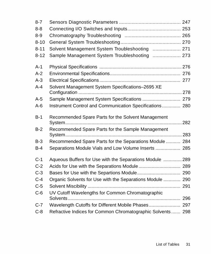
8-7 Sensors Diagnostic Parameters ............................................ 2478-8 Connecting I/O Switches and Inputs...................................... 2538-9 Chromatography Troubleshooting ........................................ 2658-10 General System Troubleshooting........................................... 2708-11 Solvent Management System Troubleshooting .................... 2718-12 Sample Management System Troubleshooting .................... 273
A-1 Physical Specifications ............................................................... 276A-2 Environmental Specifications...................................................... 276A-3 Electrical Specifications .............................................................. 277A-4 Solvent Management System Specifications–2695 XE
Configuration ............................................................................... 278A-5 Sample Management System Specifications ............................. 279A-6 Instrument Control and Communication Specifications .............. 280
B-1 Recommended Spare Parts for the Solvent Management System......................................................................................... 282
B-2 Recommended Spare Parts for the Sample Management System......................................................................................... 283
B-3 Recommended Spare Parts for the Separations Module ........... 284B-4 Separations Module Vials and Low Volume Inserts ................... 285
C-1 Aqueous Buffers for Use with the Separations Module .............. 289C-2 Acids for Use with the Separations Module ................................ 289C-3 Bases for Use with the Separtions Module................................. 290C-4 Organic Solvents for Use with the Separations Module ............. 290C-5 Solvent Miscibility ....................................................................... 291C-6 UV Cutoff Wavelengths for Common Chromatographic
Solvents ...................................................................................... 296C-7 Wavelength Cutoffs for Different Mobile Phases ........................ 297C-8 Refractive Indices for Common Chromatographic Solvents ....... 298
List of Tables 31

Preface
The Waters 2695 Separations Module Operator’s Guide describes the procedures for unpacking, installing, using, maintaining, and troubleshooting the Waters® 2695 Separations Module. It also includes appendixes for specifications, spare parts, and solvent considerations.
This guide is intended for use by individuals who need to install, operate, maintain, and/or troubleshoot the Waters 2695 Separations Module.
Organization
This guide contains the following:
Chapter 1 describes the Waters 2695 Separations Module, including features and options.
Chapter 2 describes how to unpack and install the Waters 2695 Separations Module, and how to make power, fluidic, and signal connections.
Chapter 3 describes how to power on the Separations Module, prepare the solvent and sample management systems for operation, perform daily clean-up, and power off the Separations Module.
Chapter 4 describes how to control the Separations Module from the front panel.
Chapter 5 describes how to make automatic runs in stand-alone and remote control modes.
Chapter 6 describes how to create separation methods, sample sets, and sample templates.
Chapter 7 covers routine maintenance procedures.
Chapter 8 describes troubleshooting procedures for the Waters 2695 Separations Module.
Appendix A describes the specifications of the Waters 2695 Separations Module.
Appendix B lists recommended and optional spare parts.
Appendix C provides information on solvent compatibility, miscibility, degassing, and UV cutoff wavelengths.
32
Related Documentation
Waters Licenses, Warranties, and Support: Provides software license and warranty information, describes training and extended support, and tells how Waters handles shipments, damages, claims, and returns.
Waters 2695 Separations Module Quick Start Guide: Describes the basics of how to use the 2695 Separations Module in a brief, easy-to-read format.
Waters 2695 Combined Media Documentation Set: Provides electronic files in PDF format on CD-ROM of the Waters 2695 Separations Module Operator’s Guide, Waters 2695 Separations Module Quick Start Guide, and Waters 2695 PerformancePLUS Flow Chart Reference Sheet.
Documentation on the Web
Related product information and documentation can be found on the World Wide Web. Our address is http://www.waters.com.
Related Adobe Acrobat Reader Documentation
For detailed information about using Adobe® Acrobat® Reader, see the Adobe Acrobat Reader Online Guide. This guide covers procedures such as viewing, navigating, and printing electronic documentation from Adobe Acrobat Reader.
Printing This Electronic Document
Adobe Acrobat Reader lets you easily print pages, page ranges, or the entire document by selecting File > Print. For optimum print quantity, Waters recommends that you specify a PostScript® printer driver for your printer. Ideally, use a printer that supports 600 dpi print resolution.
33
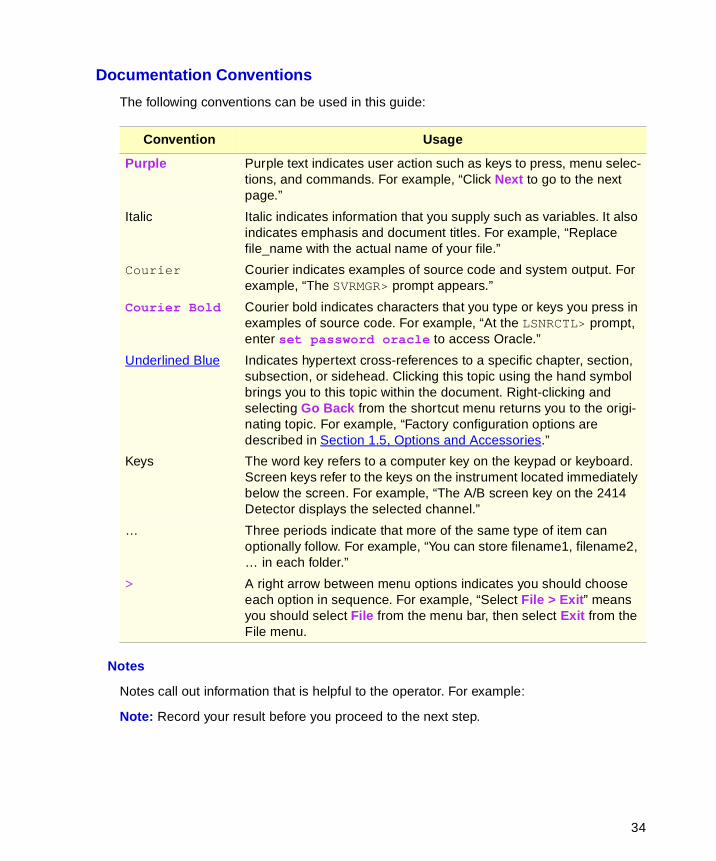
Documentation Conventions
The following conventions can be used in this guide:
Notes
Notes call out information that is helpful to the operator. For example:
Note: Record your result before you proceed to the next step.
Convention Usage
Purple Purple text indicates user action such as keys to press, menu selec-tions, and commands. For example, “Click Next to go to the next page.”
Italic Italic indicates information that you supply such as variables. It also indicates emphasis and document titles. For example, “Replace file_name with the actual name of your file.”
Courier Courier indicates examples of source code and system output. For example, “The SVRMGR> prompt appears.”
Courier Bold Courier bold indicates characters that you type or keys you press in examples of source code. For example, “At the LSNRCTL> prompt, enter set password oracle to access Oracle.”
Underlined Blue Indicates hypertext cross-references to a specific chapter, section, subsection, or sidehead. Clicking this topic using the hand symbol brings you to this topic within the document. Right-clicking and selecting Go Back from the shortcut menu returns you to the origi-nating topic. For example, “Factory configuration options are described in Section 1.5, Options and Accessories.”
Keys The word key refers to a computer key on the keypad or keyboard. Screen keys refer to the keys on the instrument located immediately below the screen. For example, “The A/B screen key on the 2414 Detector displays the selected channel.”
… Three periods indicate that more of the same type of item can optionally follow. For example, “You can store filename1, filename2, … in each folder.”
> A right arrow between menu options indicates you should choose each option in sequence. For example, “Select File > Exit” means you should select File from the menu bar, then select Exit from the File menu.
34
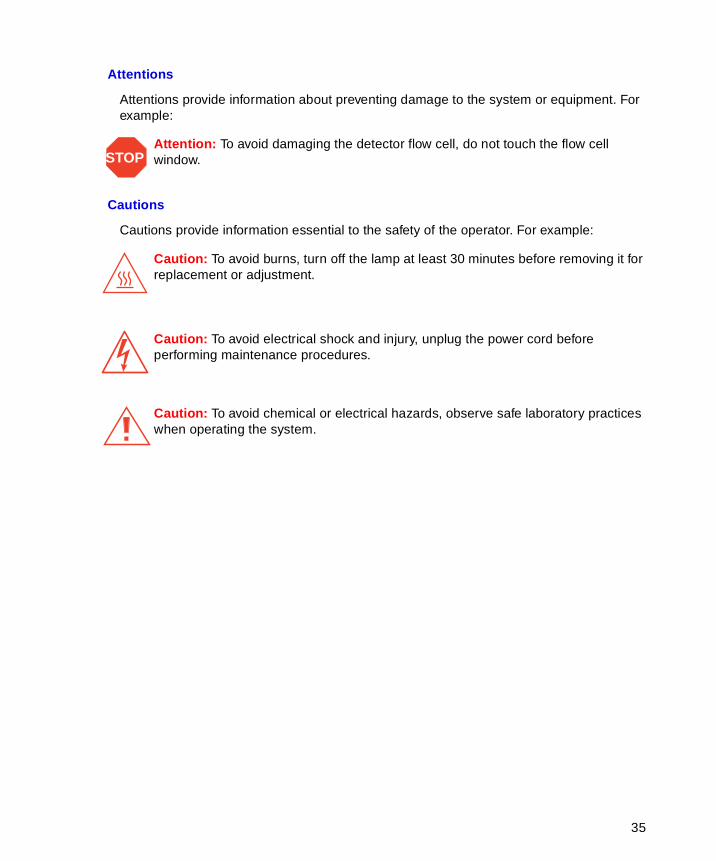
Attentions
Attentions provide information about preventing damage to the system or equipment. For example:
Cautions
Cautions provide information essential to the safety of the operator. For example:
STOPAttention: To avoid damaging the detector flow cell, do not touch the flow cell window.
Caution: To avoid burns, turn off the lamp at least 30 minutes before removing it for replacement or adjustment.
Caution: To avoid electrical shock and injury, unplug the power cord before performing maintenance procedures.
Caution: To avoid chemical or electrical hazards, observe safe laboratory practices when operating the system.
35
1
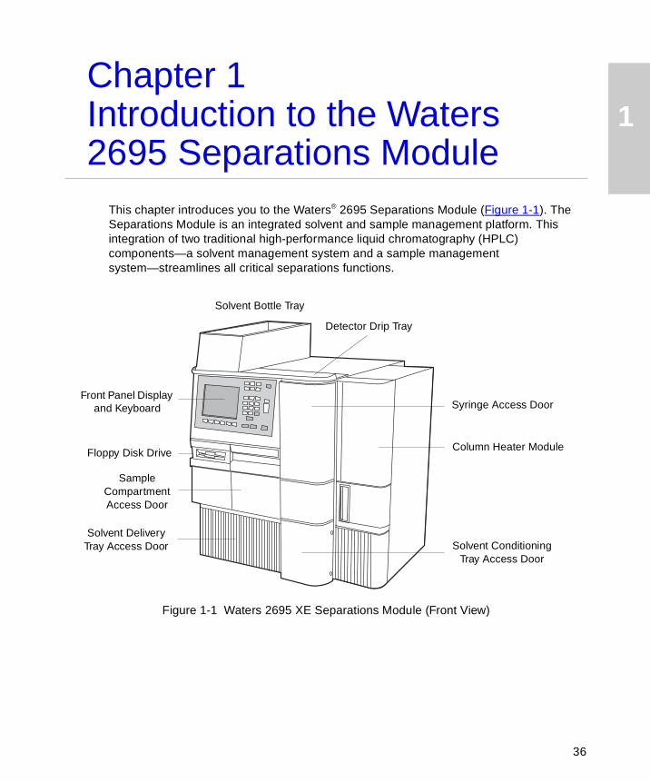
Chapter 1Introduction to the Waters 2695 Separations ModuleThis chapter introduces you to the Waters® 2695 Separations Module (Figure 1-1). The Separations Module is an integrated solvent and sample management platform. This integration of two traditional high-performance liquid chromatography (HPLC) components—a solvent management system and a sample management system—streamlines all critical separations functions.
Figure 1-1 Waters 2695 XE Separations Module (Front View)
Column Heater Module
Syringe Access DoorFront Panel Display
and Keyboard
Floppy Disk Drive
Solvent Delivery Tray Access Door Solvent Conditioning
Tray Access Door
Sample Compartment Access Door
Solvent Bottle Tray
Detector Drip Tray
36
1
1.1 Separations Module Overview
Factory Configurations
The Waters 2695 Separations Module is available from Waters in a number of configurations, differing from each other by the options that are included. These options are described in Section 1.5, Options and Accessories. The two primary configurations are designated:
• 2695 – Provides quaternary solvent, high-performance solvent delivery, integral helium sparge for solvent conditioning, integral plunger seal-wash system, 120-vial capacity sample management system, liquid-crystal display and keyboard user interface, and floppy disk drive.
• 2695 XE – Provides the capabilities of the 2695 base product, replaces the helium sparge system with a four-channel inline vacuum degasser, and adds a column heater and a sample heater/cooler.
HPLC System Configurations
The Separations Module supports RS-232, IEEE-488, and I/O connections for compatibility with a variety of HPLC system configurations. The Separations Module can function as:
• The source of I/O and timing signals in a simple, stand-alone HPLC system
• The IEEE-488 system controller in a stand-alone HPLC system using a Waters 2410 or 410 Refractive Index Detector and/or a Waters 2487 Dual Wavelength or Wasters 486 Tunable Absorbance Detector
• A component of an HPLC system controlled by the Millennium®32 Chromatography Manager, the Micromass® MassLynx™ software, or a data system using RS-232 communications
Control of Chromatographic Parameters
The Separations Module controls:
• Method programming
• Solvent composition
• Flow rate
• Plunger seal wash flow
• Needle-wash flow
• Sample injection
• Inline degassing
• External events
Introduction to the Waters 2695 Separations Module 37
1
• Operation of detectors over the IEEE-488 interface bus
• Column heating (if installed)
• Sample heating/cooling (if installed)
• Helium sparge rate (if installed)
• Binary code device (if installed)
• Bar code reader (if installed)
The Separations Module expands the traditional concept of an HPLC method to include all parameters that can influence a chromatographic separation. This approach takes a number of parameters such as pressure limits and syringe draw rates that are usually included in an instrument configuration and makes them part of the separation method. You can program the values of these parameters to change from method to method without having to set up the instrument before each run.
Spill Protection
All fluid-handling areas of the Separations Module contain spill protection; spilled solvent is routed to the waste line connectors below the front panel. A drip tray is provided for the top cover to provide leak protection if you decide to place a detector on top of the Separations Module. A solvent bottle tray provides storage for up to four 1-L solvent reservoirs and one 250-mL wash solvent reservoir and leak protection for up to a 2-L spill.
Methods Storage and Retrieval
The Separations Module can export to, and import separation methods, sample sets, and sample templates from, standard PC-formatted, 3.5-inch floppy diskettes using the built-in floppy diskette drive. This simplifies transfer of methods from system to system.
Note: The Waters 2695 Separations Module is immune to PC viruses.
Record-Keeping Functions
The Separations Module automatically records the following information:
• Total number of injections
• Total solvent usage (pumped through the system)
• System errors
• Programmed operating conditions for each run
You can:
• Print this information on an attached printer
• Transfer this information to an external device using the RS-232 bus
• Export this information to a floppy disk as an ASCII file
Separations Module Overview 38
1
1.2 Solvent Management System Overview
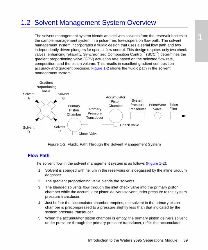
The solvent management system blends and delivers solvents from the reservoir bottles to the sample management system in a pulse-free, low-dispersion flow path. The solvent management system incorporates a fluidic design that uses a serial flow path and two independently driven plungers for optimal flow control. This design requires only two check valves, enhancing reliability. Synchronized Composition Control™ (SCC™) determines the gradient proportioning valve (GPV) actuation rate based on the selected flow rate, composition, and the piston volume. This results in excellent gradient composition accuracy and gradient precision. Figure 1-2 shows the fluidic path in the solvent management system.
Figure 1-2 Fluidic Path Through the Solvent Management System
Flow Path
The solvent flow in the solvent management system is as follows (Figure 1-2):
1. Solvent is sparged with helium in the reservoirs or is degassed by the inline vacuum degasser.
2. The gradient proportioning valve blends the solvents.
3. The blended solvents flow through the inlet check valve into the primary piston chamber while the accumulator piston delivers solvent under pressure to the system pressure transducer.
4. Just before the accumulator chamber empties, the solvent in the primary piston chamber is precompressed to a pressure slightly less than that indicated by the system pressure transducer.
5. When the accumulator piston chamber is empty, the primary piston delivers solvent under pressure through the primary pressure transducer, refills the accumulator
Primary Piston
Chamber
Prime/Vent Valve
System Pressure
Transducer
Accumulator Piston
Chamber
Check Valve
Check Valve
Gradient Proportioning
ValveSolvent
ASolvent
B
SolventD
SolventC
Primary Pressure
Transducer
Inline Filter
Introduction to the Waters 2695 Separations Module 39
1
piston chamber, and delivers solvent under pressure through the system pressure transducer, while maintaining a constant flow through the system. The cycle repeats, beginning at step 3.
6. The system pressure transducer measures the operating pressure. A software algorithm compares the primary head pressure and the system pressure readings and regulates the precompression step to balance the pressures, providing a smooth, ripple-free flow.
7. Flow continues from the system pressure transducer outlet to the prime/vent valve and into an inline filter.
8. After passing through an inline filter, the solvent flow proceeds to the sample management system.
Solvent Blending
The gradient proportioning valve (GPV) blends up to four solvents in any combination you choose. The sum of the four solvents must equal 100%. The GPV produces predictable gradient segments regardless of solvent compressibility and system back pressure. Solvent selection and proportioning take place on the low-pressure (intake) side of the solvent delivery system. Solvents continue to blend in each of the piston chambers.
Solvent Bottle Tray
The solvent bottle tray holds up to four 1-L reservoirs and one 250-mL wash reservoir, and can contain a 2-L spill. The tray is sized to fit on top of the drip tray at the top of the Separations Module, as shown in Figure 1-1.
Prime/Vent Valve
The prime/vent valve allows you to attach a syringe with which you can draw solvent through the solvent management system.
Plunger Seal-Wash System
The seal-wash solvent lubricates the plunger and flushes away any solvent or dried salts forced past the plunger seal from the high-pressure side of each piston chamber. This wash cycle extends the life of the seals. The plunger seal wash system operates as follows:
1. Plunger seal wash solvent flows from a reservoir to the solenoid wash pump, and then to a cavity behind the main plunger seal in the primary head.
2. Flow continues out of the head and into the cavity behind the plunger seal in the accumulator head.
3. From the accumulator head, wash solvent flows to waste.
When the solvent management system is delivering solvent, the plunger seal wash pump intermittently circulates the wash solvent according to the time interval you select.
Solvent Management System Overview 40
1
Loss of Prime Protection
The Separations Module automatically stops when the operating pressure remains below 25 psi (1.7 bar, 172 kPa) for 50 cycles of the solvent delivery mechanics when a loss of prime occurs due to an empty solvent reservoir.
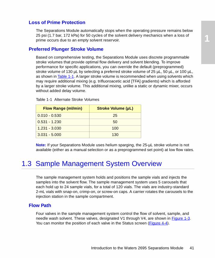
Preferred Plunger Stroke Volume
Based on comprehensive testing, the Separations Module uses discrete programmable stroke volumes that provide optimal flow delivery and solvent blending. To improve performance for specific applications, you can override the default (preprogrammed) stroke volume of 130 µL by selecting a preferred stroke volume of 25 µL, 50 µL, or 100 µL, as shown in Table 1-1. A larger stroke volume is recommended when using solvents which may require additional mixing (e.g. trifluoroacetic acid [TFA] gradients) which is afforded by a larger stroke volume. This additional mixing, unlike a static or dynamic mixer, occurs without added delay volume.
Note: If your Separations Module uses helium sparging, the 25-µL stroke volume is not available (either as a manual selection or as a preprogrammed set point) at low flow rates.
1.3 Sample Management System Overview
The sample management system holds and positions the sample vials and injects the samples into the solvent flow. The sample management system uses 5 carousels that each hold up to 24 sample vials, for a total of 120 vials. The vials are industry-standard 2-mL vials with snap-on, crimp-on, or screw-on caps. A carrier rotates the carousels to the injection station in the sample compartment.
Flow Path
Four valves in the sample management system control the flow of solvent, sample, and needle wash solvent. These valves, designated V1 through V4, are shown in Figure 1-3. You can monitor the position of each valve in the Status screen (Figure 4-4).
Table 1-1 Alternate Stroke Volumes
Flow Range (ml/min) Stroke Volume (µL)
0.010 - 0.530 25
0.531 - 1.230 50
1.231 - 3.030 100
3.031 - 5.000 130
Introduction to the Waters 2695 Separations Module 41
1
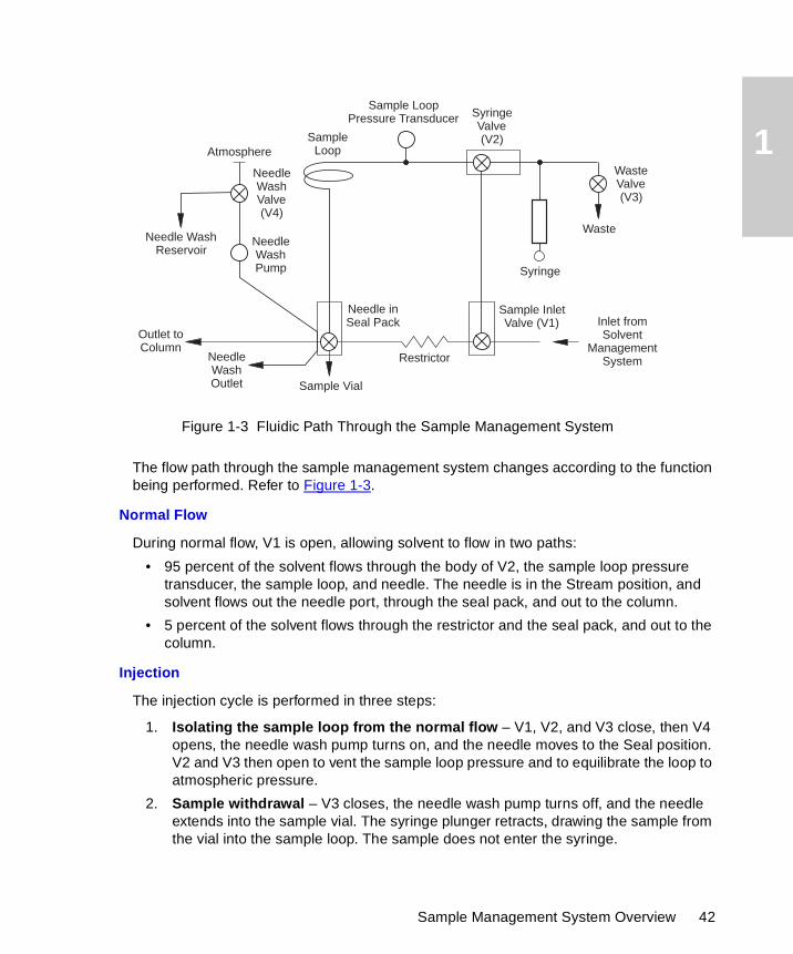
Figure 1-3 Fluidic Path Through the Sample Management System
The flow path through the sample management system changes according to the function being performed. Refer to Figure 1-3.
Normal Flow
During normal flow, V1 is open, allowing solvent to flow in two paths:
• 95 percent of the solvent flows through the body of V2, the sample loop pressure transducer, the sample loop, and needle. The needle is in the Stream position, and solvent flows out the needle port, through the seal pack, and out to the column.
• 5 percent of the solvent flows through the restrictor and the seal pack, and out to the column.
Injection
The injection cycle is performed in three steps:
1. Isolating the sample loop from the normal flow – V1, V2, and V3 close, then V4 opens, the needle wash pump turns on, and the needle moves to the Seal position. V2 and V3 then open to vent the sample loop pressure and to equilibrate the loop to atmospheric pressure.
2. Sample withdrawal – V3 closes, the needle wash pump turns off, and the needle extends into the sample vial. The syringe plunger retracts, drawing the sample from the vial into the sample loop. The sample does not enter the syringe.
Sample LoopPressure Transducer
Syringe
SyringeValve(V2)
Sample InletValve (V1) Inlet from
SolventManagement
System
Outlet toColumn
Needle inSeal Pack
NeedleWashValve(V4)
WasteValve(V3)
Needle WashReservoir
NeedleWashOutlet
SampleLoop
Waste
Restrictor
Sample Vial
Needle WashPump
Atmosphere
Sample Management System Overview 42
1
3. Sample injection – V2 closes, V3 opens, and the needle moves to the stream position to pressurize the sample loop. V1 opens, allowing the solvent to return to the normal flow. The solvent pushes the sample out of the sample loop, through the needle, and out to the column. The syringe returns to the home position, expelling drawn solvent to waste, and V3 closes.
Carousel Configuration
Each carousel is identified by color and letter and has a unique position on the carousel carrier. The Separations Module displays a warning if you attempt an injection with a carousel in the wrong position (refer to the Verify Carousel Placement parameter, Section 3.2.1, Setting Configuration Parameters). You can perform from 1 to 99 injections per sample vial, and you can offset the depth of the needle in the vial for small sample volumes, small injection volumes, or to compensate for variations in vial bottom thickness (Table B-4). Offsets may also be necessary when you use low-volume inserts in the sample vials.
Spills and condensation in the sample compartment are routed to a waste connection below the front panel.
You can load a carousel into the carrier while an injection is being made. An open-door sensor prevents the carrier from automatically advancing while you load a carousel.
Vial Presence
A light-emitting diode assembly checks for the presence of a vial before the needle moves to the Draw position. This prevents air from being accidentally injected into the solvent stream if a programmed vial position is accidentally left empty. Refer to the Verify vial presence parameter in Section 3.2.1, Setting Configuration Parameters.
Syringe Assembly
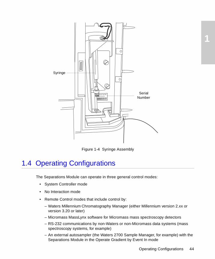
The syringe assembly is located behind a front panel door for ease of access, as shown in Figure 1-4. The Separations Module uses a standard 250-µL syringe; as an option, you can install either a 25-µL or 2500-µL syringe. Refer to Section 7.3.3, Replacing the Syringe, for the procedure to change the syringe. Note that the Separations Module serial number is located on the syringe mounting plate.
Introduction to the Waters 2695 Separations Module 43
1
Figure 1-4 Syringe Assembly
1.4 Operating Configurations
The Separations Module can operate in three general control modes:
• System Controller mode
• No Interaction mode
• Remote Control modes that include control by:
– Waters Millennium Chromatography Manager (either Millennium version 2.xx or version 3.20 or later)
– Micromass MassLynx software for Micromass mass spectroscopy detectors
– RS-232 communications by non-Waters or non-Micromass data systems (mass spectroscopy systems, for example)
– An external autosampler (the Waters 2700 Sample Manager, for example) with the Separations Module in the Operate Gradient by Event In mode
Syringe
Serial Number##E98SM4683M
Model Code SM4
Operating Configurations 44

1
1.4.1 System Controller Mode
In this mode, the Separations Module functions as the HPLC system controller. You can perform runs manually or automatically in the System Controller mode. For a manual run, you input parameter values and selections through the front panel of the Separations Module. For an automatic run, you use separation methods, sample sets and/or sample templates to control the Separations Module. Refer to Chapter 4, Front Panel Control, for information on using the front panel to control runs. Refer to Chapter 6, Creating Methods, Sample Sets, and Sample Templates, for procedures to create and store separations methods, sample sets, and sample templates.
Depending on your system components, you can connect the Separations Module to other components using:
• IEEE-488 (digital) signal connections for Waters detectors
• I/O (analog) signal connections (hard wire cables)
• RS-232 (digital) signal connections for printers or integrators
Use the procedures described in Chapter 4, Front Panel Control, to control the HPLC system in the System Controller mode.
Digital Signal Connections for System Controller Operation
Figure 1-5 illustrates a typical HPLC system configuration where the Separations Module (in System Controller mode) uses only digital signal connections to control the HPLC system components.
Figure 1-5 Digital Signal Control of an HPLC System
In the System Controller mode, the Separations Module can control up to three detector channels on the IEEE-488 bus (two UV detector channels and one RI detector channel). The detectors are:
• Waters 2410 or 410 Differential Refractometer
RS-232 Cable
2695 Separations Module
Waters 2487Dual Wavelength
UV Detector
Waters 2410 RI Detector
Printer
IEEE-488Connector
IEEE-488 Connector
Introduction to the Waters 2695 Separations Module 45
1
• Waters 2487 Dual Wavelength or 486 Tunable Absorbance Detector (any combination of up to two channels)
In this type of system, you specify detector parameters in the detector table. During a run, commands such as to change wavelength or to change sensitivity are sent to the detector(s) at specified times. Refer to Section 6.2.6, Setting Detector Parameters, for details on setting up a detector table. The Separations Module does not process detector data. Detector results and other system data are sent directly to a data acquisition system, integrator, or chart recorder.
In addition to the IEEE-488 controlled detectors, you can use RS-232 and I/O connections to control other components that do not support the IEEE-488 interface bus.
Refer to Section 2.7.2, Digital Signal Connections, for details on making digital signal connections.
1.4.2 No Interaction Mode
In this mode, the Separations Module controls non-IEEE-488 devices in the HPLC system using the I/O connections on its rear panel. This mode disconnects the Separations Module from the IEEE-488 interface bus. Use this mode if you want to suspend communications with a connected Millennium Chromatography Workstation and operate system components from their front panels.
Input/Output (I/O) Signal Connections for No Interaction Mode
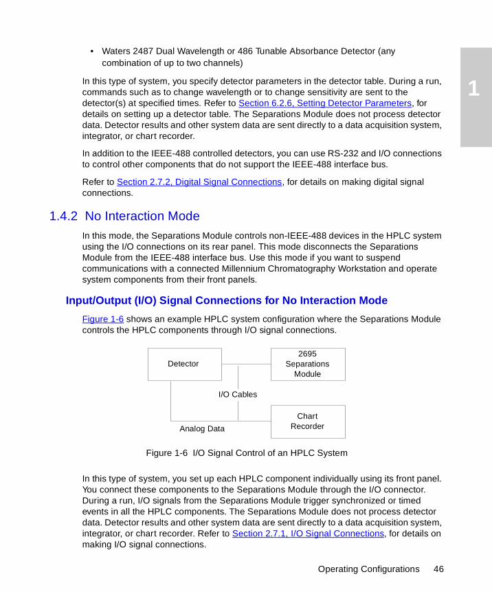
Figure 1-6 shows an example HPLC system configuration where the Separations Module controls the HPLC components through I/O signal connections.
Figure 1-6 I/O Signal Control of an HPLC System
In this type of system, you set up each HPLC component individually using its front panel. You connect these components to the Separations Module through the I/O connector. During a run, I/O signals from the Separations Module trigger synchronized or timed events in all the HPLC components. The Separations Module does not process detector data. Detector results and other system data are sent directly to a data acquisition system, integrator, or chart recorder. Refer to Section 2.7.1, I/O Signal Connections, for details on making I/O signal connections.
2695Separations
Module
I/O Cables
Detector
ChartRecorderAnalog Data
Operating Configurations 46
1
1.4.3 Remote Control Mode
In a remote control mode, the Separations Module and the other HPLC system components are controlled by the Millennium Chromatography Manager, by Micromass MassLynx software, by a non-Waters or non-Micromass data system using RS-232 (ASCII or binary) communications, or by an external autosampler with the Separations Module in the Operate Gradient by Event In mode.
In the Operate Gradient by Event In mode, the Separations Module is connected to an external autosampler (a Waters 2700 Sample Manager, for example). In this configuration, the Separations Module provides the gradient functionality for the system, and the external autosampler provides the sampling/injection functionality for the system. The external autosampler, which is connected to the I/O signal connector on the Separations Module, signals the Solvent Management System to begin a gradient. This mode does not allow the Separations Module to interface with instruments on the IEEE-488 interface bus.
Use the procedures in Chapter 5, Making Automatic Runs, to set up the Separations Module for remote control.
Millennium Control
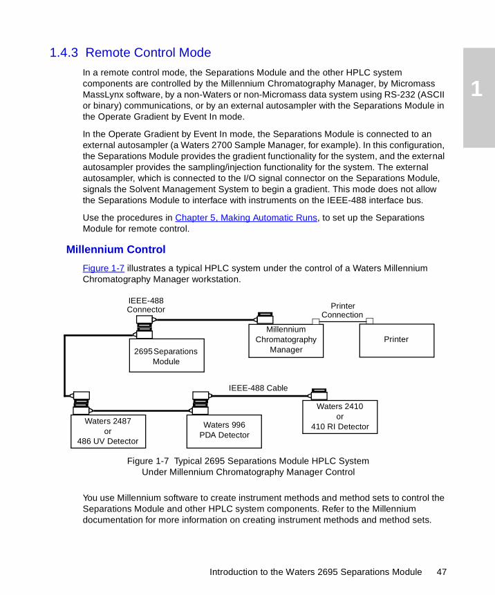
Figure 1-7 illustrates a typical HPLC system under the control of a Waters Millennium Chromatography Manager workstation.
Figure 1-7 Typical 2695 Separations Module HPLC SystemUnder Millennium Chromatography Manager Control
You use Millennium software to create instrument methods and method sets to control the Separations Module and other HPLC system components. Refer to the Millennium documentation for more information on creating instrument methods and method sets.
IEEE-488
IEEE-488 Cable
Waters 996 PDA Detector
Waters 2487or
486 UV Detector
2695 Separations Module
Millennium Chromatography
ManagerPrinter
Printer
Waters 2410or
410 RI Detector
Connector Connection
Introduction to the Waters 2695 Separations Module 47
1
All detectors currently supported by Millennium software can be used with the Separations Module, including the Waters 996/2996 Photodiode Array Detector. Data from the detectors are sent over the IEEE-488 interface bus to the Millennium software for processing.
MassLynx Control
When you control the Separations Module by MassLynx software, you use the MassLynx Inlet Editor to define operating parameters for the Separations Module and detector(s) (other than the mass spectrometer) used in the LC/MS system. Refer to the MassLynx documentation for more information on controlling the Waters 2695 Separations Module.
RS-232 Control
To set parameters that remotely control the Separations Module from a data system that uses RS-232 (ASCII or binary) communications, refer to the documentation that comes with the data system.
Operate Gradient by Event In Control
Note: When you connect the Separations Module by its I/O terminal strip to an external autosampler using the Operate Gradient by Event In configuration, the external autosampler signals the Solvent Management System to begin a gradient. This mode does not allow the Separations Module to interface with instruments on the IEEE-488 bus.
1.5 Options and Accessories
A number of options for the 2695 Separations Module are available to suit your applications and site requirements. You can display a list of the hardware options that are installed in your Separations Module by pressing the Options screen key in the Configure screen. Refer to Section 3.2, Configuring the Separations Module, for details on displaying the Configure screen.
Power Supply
The 2695 Separations Module is factory equipped with a 600 watt (W) power supply. This provides immediate compatibility for the addition of a column heater/cooler.
The power supply by design is short circuit protected and does not feature external replacement fuses. The power supply is reset by power cycling the instrument.
Before adding a column heater/cooler to a Separations Module, contact your Waters Technical or Service representative at 800 252-4752, U.S. and Canadian customers only. Other customers, contact your local Waters subsidiary, or contact the Waters corporate headquarters in Milford, Massachusetts (U.S.A.).
Options and Accessories 48

1
Column Heater
The column heater allows you to maintain the column at temperatures from 5 °C above ambient (minimum of 20 °C) to 60 °C. An alarm warns you if the temperature varies outside of the range that you specify. The procedure to install this option is described in Section 2.8.2, Installing the Column Heater.
Sample Heater/Cooler
The sample heater/cooler allows you to maintain the sample compartment at temperatures from 4 to 40 °C for optimizing sample stability and/or solubility. This option is installed at the factory on the 2695 XE. The heater/cooler mounts through the rear panel of the Separations Module and uses four Peltier devices for temperature control.
Bar Code Reader
The bar code reader allows you to scan bar-coded sample vials to eliminate recording errors and add another level of sample traceability. A side panel covers the bar code reader to prevent exposure to the laser.
The Waters 2695 Bar Code Reader reads Code 128C labels, which specify a six-digit code that provides a scan range of one million numbers (000,000 to 999,999), with labels that fit on industry-standard 2-mL vials. The option also includes a roll of 2,500 labels that are specially coated to resist common chromatographic solvents. Attaching labels to the sample vials is the only step required to use the bar code reader.
PerformancePLUS Inline Degasser
The design of the PerformancePLUS™ Inline Degasser combines a unique, variable-speed, continuously operating vacuum pump with innovative, high efficiency, low internal volume degasser chambers. This technology dramatically shortens instrument priming and equilibration times, allowing the system to become operational faster from an idle state or following a solvent change. Electronic control strategies are rugged, providing reliable long-term performance needed for continuous operation.
The degasser’s Zero Hysteresis-Constant Run stepping motor-driven vacuum pump has been specifically designed and developed for membrane degassing of HPLC mobile phases. The continuously running pump cycles between high speeds, to provide rapid vacuum pull-down, while the low speed sustains a consistent vacuum level. This approach enables rapid vacuum equilibration for faster eluent equilibration. The continuous operating mode improves chromatographic performance for many high-sensitivity applications by eliminating the detector baseline drift or cycle that may be caused by pump hysteresis in discontinuous operating modes.
The PerformancePLUS Inline Degasser chambers achieve degassing efficiencies comparable to large-volume chambers, but with a fraction of the volume. Reduced from <11 mL to <500 uL, the degasser’s low-volume chambers substantially reduce prime effort, speed up solvent changover, and increase reliability.
Introduction to the Waters 2695 Separations Module 49
1
Degasser Considerations
Degassing efficiency is based upon the solvent gas load and the length of time that the solvent remains in its respective vacuum chamber. Gas removal efficiency decreases as the solvent flow rate increases because the solvent is in the vacuum chamber for less time. Using a normal analytical flow rate range of 0.000 to 5.000 mL/min, the degasser removes most of the dissolved gasses. Because you can perform dry and wet priming in the Separations Module at flow rates greater than 5.000 mL/min, you need to expose the solvents to the degasser vacuum for a short time (after priming) at zero flow rate. This solvent equilibrating process is described in the “Equilibrating Solvents in the Vacuum Degasser” discussion in Section 4.4.2, Performing a Wet Prime.
Vacuum Degasser Pressure Transducers
Waters 2695 Separations Modules come equipped with an absolute pressure transducer (APT). The APT is unaffected by altitude or barometric changes. Table 1-1 lists the attributes of APT-equipped Separations Modules.
Syringes
You can install a 25-µL, 250-µL, or 2500-µL sample syringe in the Separations Module. The 250-µL syringe is standard. Refer to Section 7.3.3, Replacing the Syringe, for the procedure to replace the syringe.
Sample Loops
You can install an additional 100-µL sample loop or a larger sample loop to inject sample volumes greater than 100 µL. Refer to Section 2.8.1, Installing an Optional Sample Loop, for the procedure to install an optional sample loop.
Table 1-1 Absolute Pressure Transducer Attributes
Item Absolute Pressure Transducer
Units displayed psia, kPa, bar
Sign of displayed unit Positive
Theoretical maximum vacuuma
a. Based on 1 atm at sea level.
0 psia
Operating rangeb
b. Using the default vacuum pressure threshold.
3.2 to 0 psiac
c. If pressure is out of range, an asterisk (*) is displayed in the pressure field.
“Typical” value 1.4 to 2.0 psia
More vacuum Smaller number is displayed
Options and Accessories 50
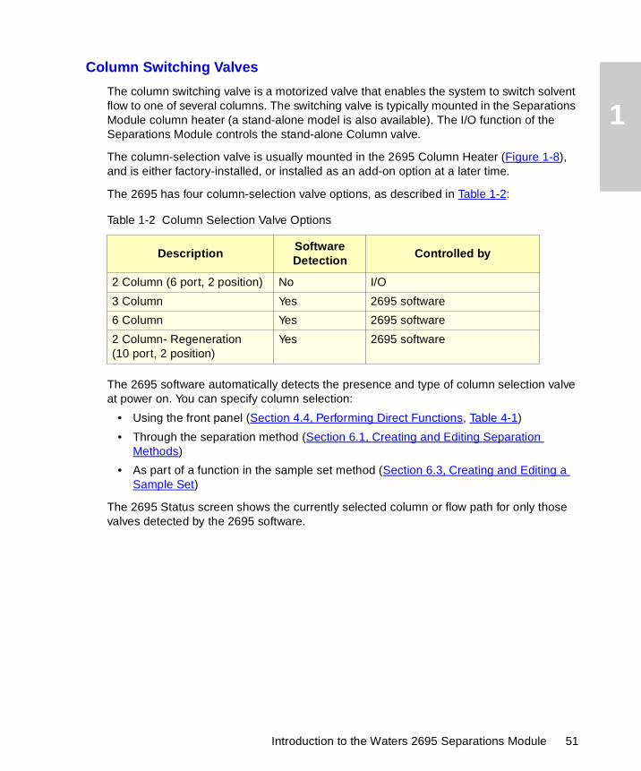
1
Column Switching Valves
The column switching valve is a motorized valve that enables the system to switch solvent flow to one of several columns. The switching valve is typically mounted in the Separations Module column heater (a stand-alone model is also available). The I/O function of the Separations Module controls the stand-alone Column valve.
The column-selection valve is usually mounted in the 2695 Column Heater (Figure 1-8), and is either factory-installed, or installed as an add-on option at a later time.
The 2695 has four column-selection valve options, as described in Table 1-2:
The 2695 software automatically detects the presence and type of column selection valve at power on. You can specify column selection:
• Using the front panel (Section 4.4, Performing Direct Functions, Table 4-1)
• Through the separation method (Section 6.1, Creating and Editing Separation Methods)
• As part of a function in the sample set method (Section 6.3, Creating and Editing a Sample Set)
The 2695 Status screen shows the currently selected column or flow path for only those valves detected by the 2695 software.
Table 1-2 Column Selection Valve Options
DescriptionSoftware Detection
Controlled by
2 Column (6 port, 2 position) No I/O
3 Column Yes 2695 software
6 Column Yes 2695 software
2 Column- Regeneration(10 port, 2 position)
Yes 2695 software
Introduction to the Waters 2695 Separations Module 51
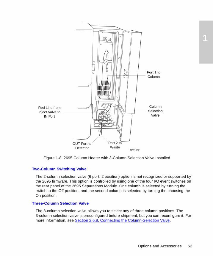
1
Figure 1-8 2695 Column Heater with 3-Column Selection Valve Installed
Two-Column Switching Valve
The 2-column selection valve (6 port, 2 position) option is not recognized or supported by the 2695 firmware. This option is controlled by using one of the four I/O event switches on the rear panel of the 2695 Separations Module. One column is selected by turning the switch to the Off position, and the second column is selected by turning the choosing the On position.
Three-Column Selection Valve
The 3-column selection valve allows you to select any of three column positions. The 3-column selection valve is preconfigured before shipment, but you can reconfigure it. For more information, see Section 2.6.8, Connecting the Column-Selection Valve.
TP01632
Column Selection
Valve
Port 1 to Column
Red Line from Inject Valve to
IN Port
OUT Port to Detector
Port 2 to Waste
Options and Accessories 52
1
Six-Column Selection Valve
The 6-column selection valve allows you to select any one of six column positions, and you can specify any position as bypass or waste. For more information, refer to Section 2.6.8, Connecting the Column-Selection Valve.
Two-Column Regeneration Valve
The 2-column regeneration valve allows you to perform LC operations using one column while the second column is undergoing regeneration by a second solvent delivery system. For more information, refer to Section 2.6.8, Connecting the Column-Selection Valve.
BCD Module
The BCD (Binary Coded Decimal) option provides sample tracking by automatically transmitting vial numbers in BCD format from the Separations Module to a non-Waters or non-Micromass data system (typically a LIMS system).
Introduction to the Waters 2695 Separations Module 53
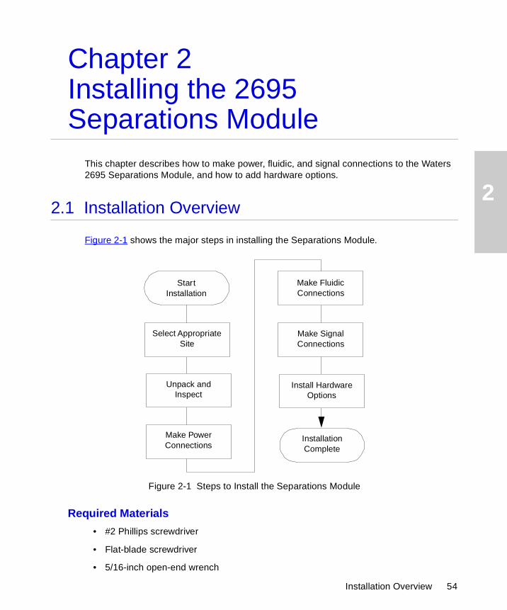
2
Chapter 2Installing the 2695 Separations Module
This chapter describes how to make power, fluidic, and signal connections to the Waters 2695 Separations Module, and how to add hardware options.
2.1 Installation Overview
Figure 2-1 shows the major steps in installing the Separations Module.
Figure 2-1 Steps to Install the Separations Module
Required Materials
• #2 Phillips screwdriver
• Flat-blade screwdriver
• 5/16-inch open-end wrench
Installation Complete
Select Appropriate Site
Unpack and Inspect
Make Power Connections
Make Signal Connections
Make Fluidic Connections
Install Hardware Options
StartInstallation
Installation Overview 54
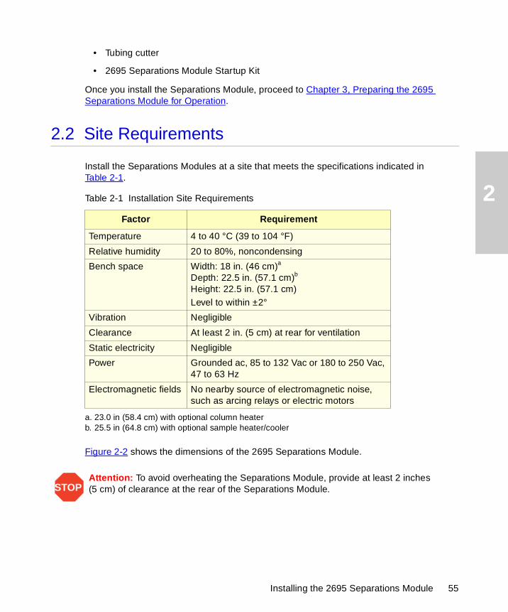
2
• Tubing cutter
• 2695 Separations Module Startup Kit
Once you install the Separations Module, proceed to Chapter 3, Preparing the 2695 Separations Module for Operation.
2.2 Site Requirements
Install the Separations Modules at a site that meets the specifications indicated in Table 2-1.
Figure 2-2 shows the dimensions of the 2695 Separations Module.
Table 2-1 Installation Site Requirements
Factor Requirement
Temperature 4 to 40 °C (39 to 104 °F)
Relative humidity 20 to 80%, noncondensing
Bench space Width: 18 in. (46 cm)a
Depth: 22.5 in. (57.1 cm)b
Height: 22.5 in. (57.1 cm)Level to within ±2°
a. 23.0 in (58.4 cm) with optional column heaterb. 25.5 in (64.8 cm) with optional sample heater/cooler
Vibration Negligible
Clearance At least 2 in. (5 cm) at rear for ventilation
Static electricity Negligible
Power Grounded ac, 85 to 132 Vac or 180 to 250 Vac, 47 to 63 Hz
Electromagnetic fields No nearby source of electromagnetic noise, such as arcing relays or electric motors
STOPAttention: To avoid overheating the Separations Module, provide at least 2 inches(5 cm) of clearance at the rear of the Separations Module.
Installing the 2695 Separations Module 55
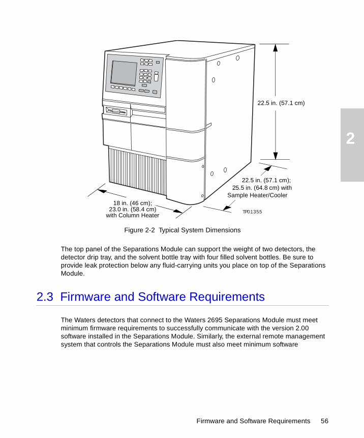
2
Figure 2-2 Typical System Dimensions
The top panel of the Separations Module can support the weight of two detectors, the detector drip tray, and the solvent bottle tray with four filled solvent bottles. Be sure to provide leak protection below any fluid-carrying units you place on top of the Separations Module.
2.3 Firmware and Software Requirements
The Waters detectors that connect to the Waters 2695 Separations Module must meet minimum firmware requirements to successfully communicate with the version 2.00 software installed in the Separations Module. Similarly, the external remote management system that controls the Separations Module must also meet minimum software
TP01355
18 in. (46 cm);
22.5 in. (57.1 cm); 25.5 in. (64.8 cm) with
Sample Heater/Cooler
22.5 in. (57.1 cm)
23.0 in. (58.4 cm)with Column Heater
Firmware and Software Requirements 56
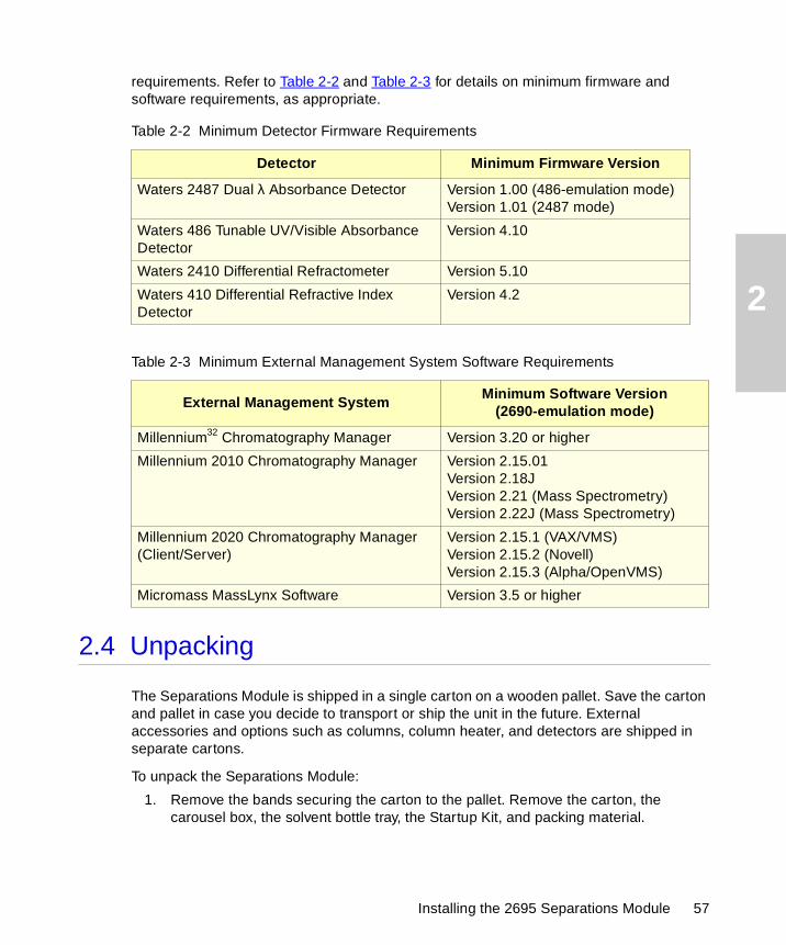
2
requirements. Refer to Table 2-2 and Table 2-3 for details on minimum firmware and software requirements, as appropriate.
2.4 Unpacking
The Separations Module is shipped in a single carton on a wooden pallet. Save the carton and pallet in case you decide to transport or ship the unit in the future. External accessories and options such as columns, column heater, and detectors are shipped in separate cartons.
To unpack the Separations Module:
1. Remove the bands securing the carton to the pallet. Remove the carton, the carousel box, the solvent bottle tray, the Startup Kit, and packing material.
Table 2-2 Minimum Detector Firmware Requirements
Detector Minimum Firmware Version
Waters 2487 Dual λ Absorbance Detector Version 1.00 (486-emulation mode)Version 1.01 (2487 mode)
Waters 486 Tunable UV/Visible Absorbance Detector
Version 4.10
Waters 2410 Differential Refractometer Version 5.10
Waters 410 Differential Refractive Index Detector
Version 4.2
Table 2-3 Minimum External Management System Software Requirements
External Management SystemMinimum Software Version
(2690-emulation mode)
Millennium32 Chromatography Manager Version 3.20 or higher
Millennium 2010 Chromatography Manager Version 2.15.01Version 2.18JVersion 2.21 (Mass Spectrometry)Version 2.22J (Mass Spectrometry)
Millennium 2020 Chromatography Manager (Client/Server)
Version 2.15.1 (VAX/VMS)Version 2.15.2 (Novell)Version 2.15.3 (Alpha/OpenVMS)
Micromass MassLynx Software Version 3.5 or higher
Installing the 2695 Separations Module 57
2
2. Check the contents of the carton against the packing slip to confirm that all items are included.
3. Lift the Separations Module from the pallet and place it at the site you have chosen for installation.
4. Inspect all items for damage. Immediately report any shipping damage to both the shipping company and your Waters representative. Contact Waters Customer Service at 800 252-4752, U.S. and Canadian customers only. Other customers, call your local Waters subsidiary, or call the Waters corporate headquarters in Milford, Massachusetts (U.S.A.). Refer to Waters Licenses, Warranties, and Support for complete information on shipping damages and claims.
Continue the installation by following the procedures in Section 2.5, Making Power Connections.
2.5 Making Power Connections
Proper operation of the 2695 Separations Module requires that the AC power supply is grounded and has no abrupt voltage fluctuations.
2.5.1 Making the Power Supply Connection
The Separations Module automatically adjusts for mains input voltages in two ranges:
• 85 to 132 Vac, 47 to 63 Hz
• 180 to 250 Vac, 47 to 63 Hz
To make the power supply connection:
1. Check that the Power On/Off switch is in the Off (0) position.
2. Connect the power cord to the connector on the rear panel of the Separations Module.
3. Connect the other end of the power cord to a properly grounded ac power supply. Do not power on the Separations Module until you have completed all fluidic and signal connections.
STOPAttention: To avoid injury, ensure that at least two people lift the Separations Module from the pallet to the bench.
Caution: To avoid electrical shock and possible injury, remove the power cord from the rear panel of the instrument before you perform the procedure in this section.
Making Power Connections 58
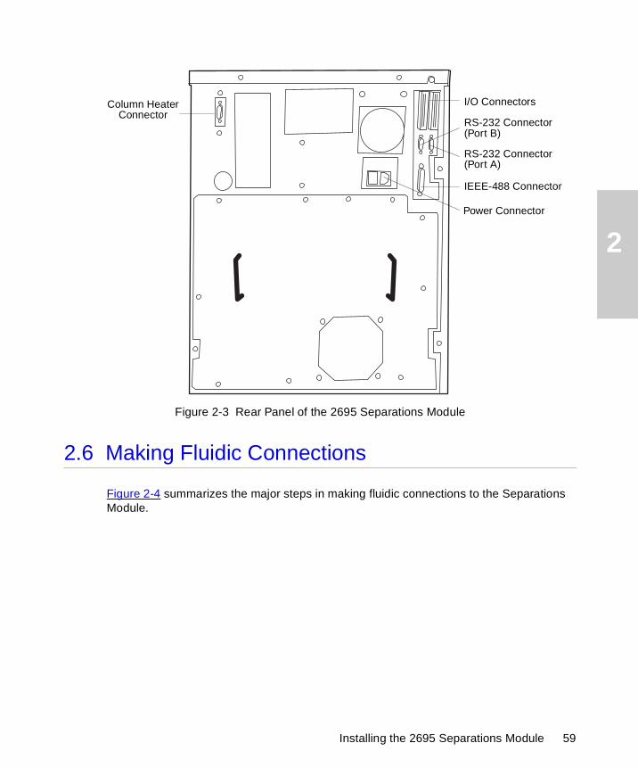
2
Figure 2-3 Rear Panel of the 2695 Separations Module
2.6 Making Fluidic Connections
Figure 2-4 summarizes the major steps in making fluidic connections to the Separations Module.
I/O Connectors
RS-232 Connector
IEEE-488 Connector
Power Connector
Column HeaterConnector
(Port A)
RS-232 Connector(Port B)
Installing the 2695 Separations Module 59
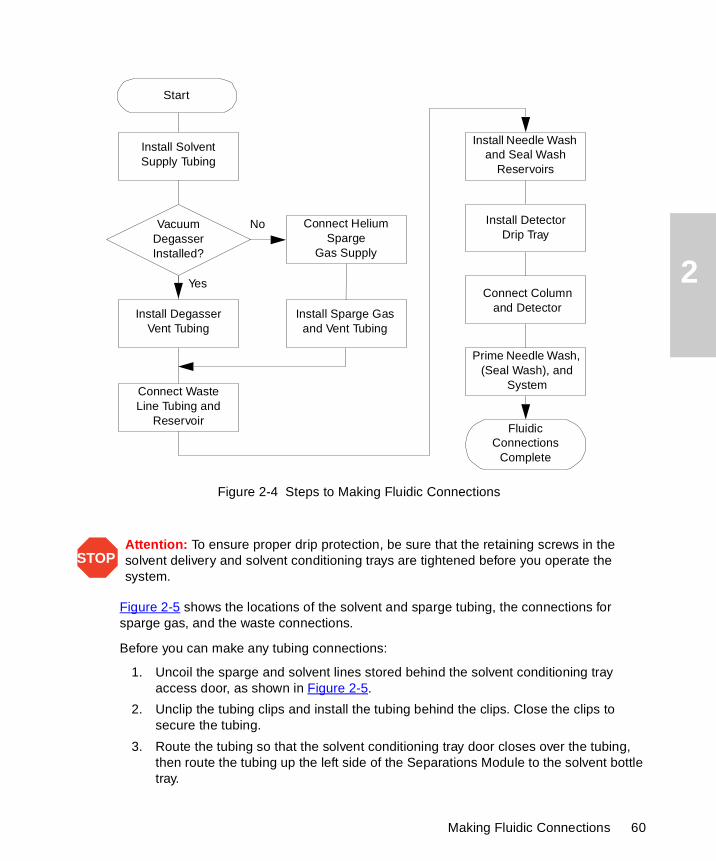
2
Figure 2-4 Steps to Making Fluidic Connections
Figure 2-5 shows the locations of the solvent and sparge tubing, the connections for sparge gas, and the waste connections.
Before you can make any tubing connections:
1. Uncoil the sparge and solvent lines stored behind the solvent conditioning tray access door, as shown in Figure 2-5.
2. Unclip the tubing clips and install the tubing behind the clips. Close the clips to secure the tubing.
3. Route the tubing so that the solvent conditioning tray door closes over the tubing, then route the tubing up the left side of the Separations Module to the solvent bottle tray.
STOPAttention: To ensure proper drip protection, be sure that the retaining screws in the solvent delivery and solvent conditioning trays are tightened before you operate the system.
Yes
No
Fluidic Connections
Complete
Install Solvent Supply Tubing
Connect Waste Line Tubing and
Reservoir
Install Needle Wash and Seal Wash
Reservoirs
Install DetectorDrip Tray
Prime Needle Wash, (Seal Wash), and
System
VacuumDegasser Installed?
Install Sparge Gas and Vent Tubing
Connect Helium Sparge
Gas Supply
Install DegasserVent Tubing
Connect Column and Detector
Start
Making Fluidic Connections 60
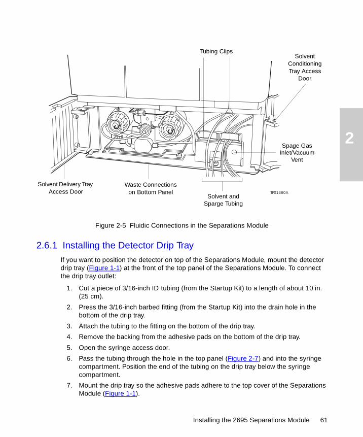
2
Figure 2-5 Fluidic Connections in the Separations Module
2.6.1 Installing the Detector Drip Tray
If you want to position the detector on top of the Separations Module, mount the detector drip tray (Figure 1-1) at the front of the top panel of the Separations Module. To connect the drip tray outlet:
1. Cut a piece of 3/16-inch ID tubing (from the Startup Kit) to a length of about 10 in. (25 cm).
2. Press the 3/16-inch barbed fitting (from the Startup Kit) into the drain hole in the bottom of the drip tray.
3. Attach the tubing to the fitting on the bottom of the drip tray.
4. Remove the backing from the adhesive pads on the bottom of the drip tray.
5. Open the syringe access door.
6. Pass the tubing through the hole in the top panel (Figure 2-7) and into the syringe compartment. Position the end of the tubing on the drip tray below the syringe compartment.
7. Mount the drip tray so the adhesive pads adhere to the top cover of the Separations Module (Figure 1-1).
TP01360A
Solvent Delivery Tray Access Door
Solvent and Sparge Tubing
Waste Connections on Bottom Panel
Tubing ClipsSolvent
Conditioning Tray Access
Door
Spage GasInlet/Vacuum
Vent
Installing the 2695 Separations Module 61
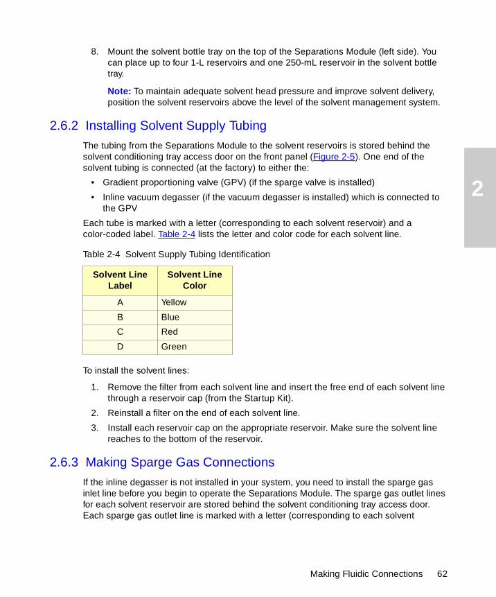
2
8. Mount the solvent bottle tray on the top of the Separations Module (left side). You can place up to four 1-L reservoirs and one 250-mL reservoir in the solvent bottle tray.
Note: To maintain adequate solvent head pressure and improve solvent delivery, position the solvent reservoirs above the level of the solvent management system.
2.6.2 Installing Solvent Supply Tubing
The tubing from the Separations Module to the solvent reservoirs is stored behind the solvent conditioning tray access door on the front panel (Figure 2-5). One end of the solvent tubing is connected (at the factory) to either the:
• Gradient proportioning valve (GPV) (if the sparge valve is installed)
• Inline vacuum degasser (if the vacuum degasser is installed) which is connected to the GPV
Each tube is marked with a letter (corresponding to each solvent reservoir) and a color-coded label. Table 2-4 lists the letter and color code for each solvent line.
To install the solvent lines:
1. Remove the filter from each solvent line and insert the free end of each solvent line through a reservoir cap (from the Startup Kit).
2. Reinstall a filter on the end of each solvent line.
3. Install each reservoir cap on the appropriate reservoir. Make sure the solvent line reaches to the bottom of the reservoir.
2.6.3 Making Sparge Gas Connections
If the inline degasser is not installed in your system, you need to install the sparge gas inlet line before you begin to operate the Separations Module. The sparge gas outlet lines for each solvent reservoir are stored behind the solvent conditioning tray access door. Each sparge gas outlet line is marked with a letter (corresponding to each solvent
Table 2-4 Solvent Supply Tubing Identification
Solvent Line Label
Solvent Line Color
A Yellow
B Blue
C Red
D Green
Making Fluidic Connections 62
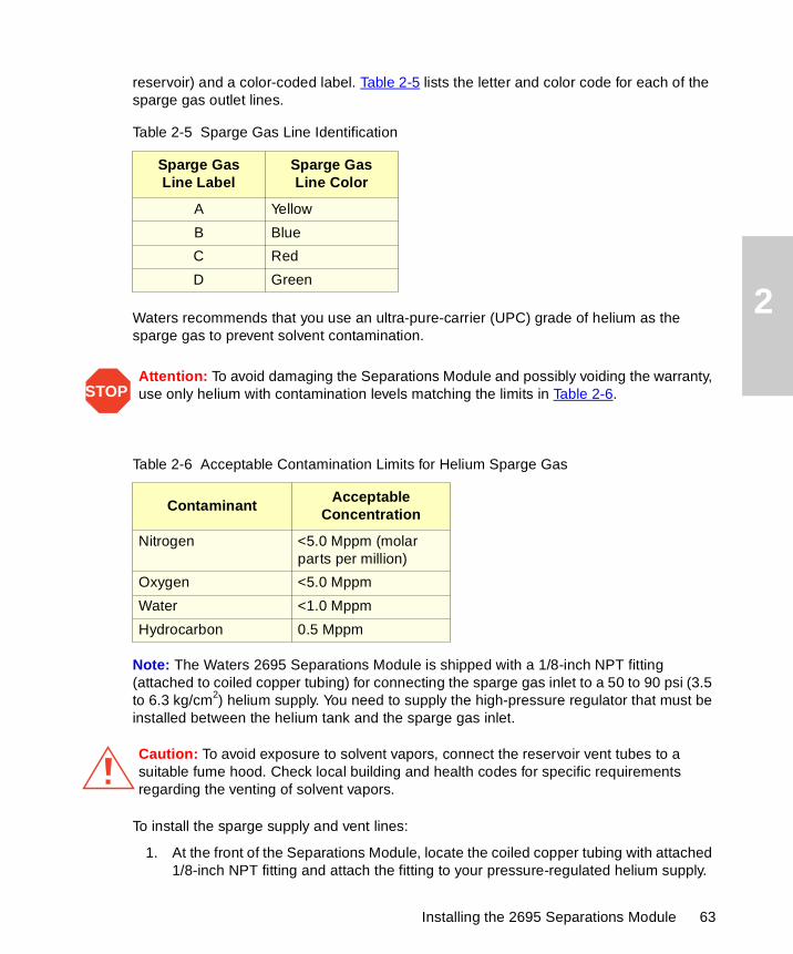
2
reservoir) and a color-coded label. Table 2-5 lists the letter and color code for each of the sparge gas outlet lines.
Waters recommends that you use an ultra-pure-carrier (UPC) grade of helium as the sparge gas to prevent solvent contamination.
Note: The Waters 2695 Separations Module is shipped with a 1/8-inch NPT fitting (attached to coiled copper tubing) for connecting the sparge gas inlet to a 50 to 90 psi (3.5 to 6.3 kg/cm2) helium supply. You need to supply the high-pressure regulator that must be installed between the helium tank and the sparge gas inlet.
To install the sparge supply and vent lines:
1. At the front of the Separations Module, locate the coiled copper tubing with attached 1/8-inch NPT fitting and attach the fitting to your pressure-regulated helium supply.
Table 2-5 Sparge Gas Line Identification
Sparge Gas Line Label
Sparge Gas Line Color
A Yellow
B Blue
C Red
D Green
STOPAttention: To avoid damaging the Separations Module and possibly voiding the warranty, use only helium with contamination levels matching the limits in Table 2-6.
Table 2-6 Acceptable Contamination Limits for Helium Sparge Gas
ContaminantAcceptable
Concentration
Nitrogen <5.0 Mppm (molar parts per million)
Oxygen <5.0 Mppm
Water <1.0 Mppm
Hydrocarbon 0.5 Mppm
Caution: To avoid exposure to solvent vapors, connect the reservoir vent tubes to a suitable fume hood. Check local building and health codes for specific requirements regarding the venting of solvent vapors.
Installing the 2695 Separations Module 63
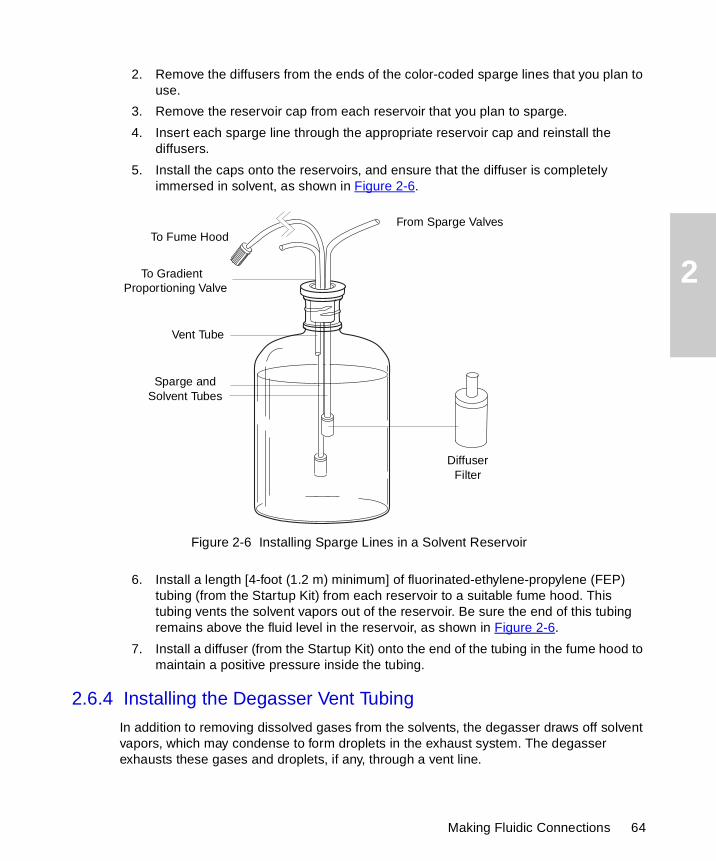
2
2. Remove the diffusers from the ends of the color-coded sparge lines that you plan to use.
3. Remove the reservoir cap from each reservoir that you plan to sparge.
4. Insert each sparge line through the appropriate reservoir cap and reinstall the diffusers.
5. Install the caps onto the reservoirs, and ensure that the diffuser is completely immersed in solvent, as shown in Figure 2-6.
Figure 2-6 Installing Sparge Lines in a Solvent Reservoir
6. Install a length [4-foot (1.2 m) minimum] of fluorinated-ethylene-propylene (FEP) tubing (from the Startup Kit) from each reservoir to a suitable fume hood. This tubing vents the solvent vapors out of the reservoir. Be sure the end of this tubing remains above the fluid level in the reservoir, as shown in Figure 2-6.
7. Install a diffuser (from the Startup Kit) onto the end of the tubing in the fume hood to maintain a positive pressure inside the tubing.
2.6.4 Installing the Degasser Vent Tubing
In addition to removing dissolved gases from the solvents, the degasser draws off solvent vapors, which may condense to form droplets in the exhaust system. The degasser exhausts these gases and droplets, if any, through a vent line.
To Fume Hood
To Gradient Proportioning Valve
From Sparge Valves
Vent Tube
Sparge and Solvent Tubes
Diffuser Filter
Making Fluidic Connections 64
2
To install the degasser vent tubing, place the free end of the degasser vent tubing in a waste container that is in a properly functioning fume hood.
2.6.5 Making Waste Line Connections
You need to make waste line connections for:
• Spill tray waste
• Condensation waste
Spill Tray Waste Line
The spill tray waste outlet is located under the front panel of the Separations Module, below the solvent conditioning tray access door (Figure 2-5).
To install the spill tray waste line:
1. Cut a length of 3/16-inch ID tubing (from the Startup Kit) long enough to reach from the spill tray waste outlet to the front of the bench.
2. Connect one end of this piece of tubing to the spill tray waste outlet.
3. Install a 90° elbow (from the Startup Kit) on the other end of the tubing.
4. Cut another length of 3/16-inch ID tubing long enough to reach from the elbow fitting to the waste reservoir.
5. Connect the tubing between the elbow and the waste reservoir.
Condensation Waste Line
The condensation waste outlet from the sample compartment is also located under the front panel of the Separations Module, to the right of the spill tray waste outlet. In addition
Caution: To avoid exposure to solvent vapors, connect the degasser exhaust tube to a suitable fume hood. Check local building and health codes for specific requirements regarding the venting of solvent vapors.
Caution: To maintain proper vacuum system operation, do not allow the vent line to become submerged. Waters recommends that the degasser vent tubing not be placed in the solvent waste reservoir.
STOPAttention: Ensure all drain lines, both inside the instrument and out, are properly connected and are not restricted by obstructions or bends. The two main drain lines exiting the front of the instrument must lay flat on the bench top without any upward travel. These drain lines must be ported to an appropriate waste container of a volume equal to or greater than that of the combined volume of all solvent reservoirs. The waste container must be at a level lower than the instrument. Always check the drain lines after moving the instrument or performing maintenance on the instrument.
Installing the 2695 Separations Module 65
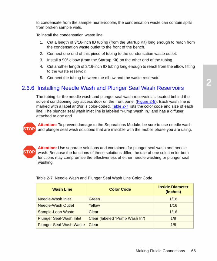
2
to condensate from the sample heater/cooler, the condensation waste can contain spills from broken sample vials.
To install the condensation waste line:
1. Cut a length of 3/16-inch ID tubing (from the Startup Kit) long enough to reach from the condensation waste outlet to the front of the bench.
2. Connect one end of this piece of tubing to the condensation waste outlet.
3. Install a 90° elbow (from the Startup Kit) on the other end of the tubing.
4. Cut another length of 3/16-inch ID tubing long enough to reach from the elbow fitting to the waste reservoir.
5. Connect the tubing between the elbow and the waste reservoir.
2.6.6 Installing Needle Wash and Plunger Seal Wash Reservoirs
The tubing for the needle wash and plunger seal wash reservoirs is located behind the solvent conditioning tray access door on the front panel (Figure 2-5). Each wash line is marked with a label and/or is color-coded. Table 2-7 lists the color code and size of each line. The plunger seal wash inlet line is labeled “Pump Wash In,” and has a diffuser attached to one end.
STOPAttention: To prevent damage to the Separations Module, be sure to use needle wash and plunger seal wash solutions that are miscible with the mobile phase you are using.
STOPAttention: Use separate solutions and containers for plunger seal wash and needle wash. Because the functions of these solutions differ, the use of one solution for both functions may compromise the effectiveness of either needle washing or plunger seal washing.
Table 2-7 Needle Wash and Plunger Seal Wash Line Color Code
Wash Line Color CodeInside Diameter
(Inches)
Needle-Wash Inlet Green 1/16
Needle-Wash Outlet Yellow 1/16
Sample-Loop Waste Clear 1/16
Plunger Seal-Wash Inlet Clear (labeled “Pump Wash In”) 1/8
Plunger Seal-Wash Waste Clear 1/8
Making Fluidic Connections 66
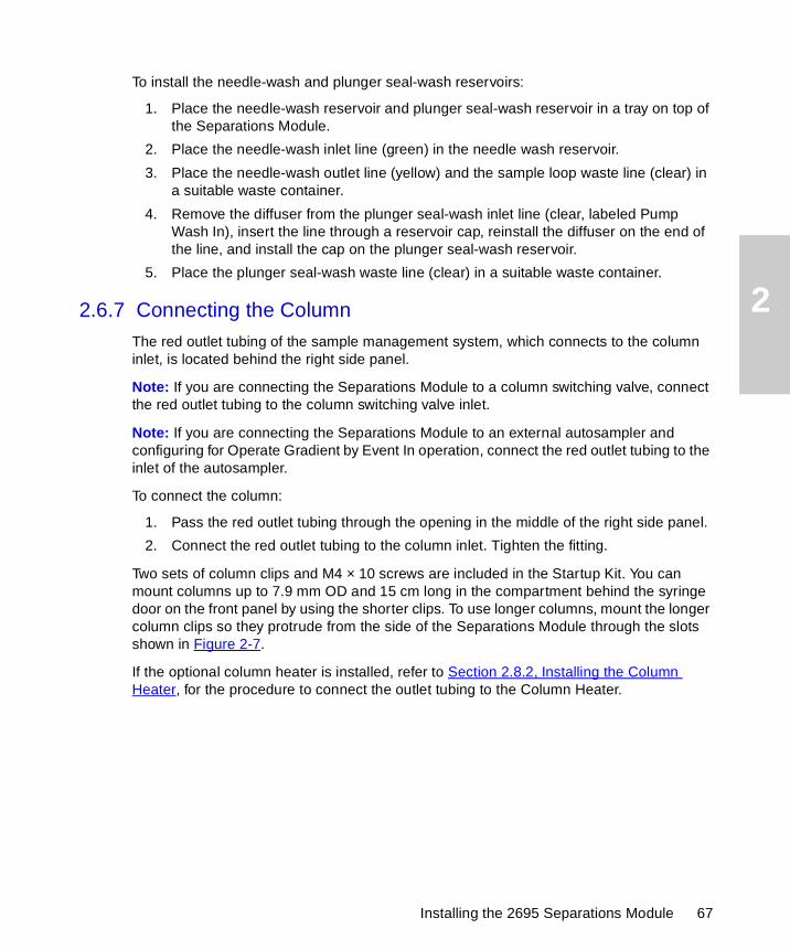
2
To install the needle-wash and plunger seal-wash reservoirs:
1. Place the needle-wash reservoir and plunger seal-wash reservoir in a tray on top of the Separations Module.
2. Place the needle-wash inlet line (green) in the needle wash reservoir.
3. Place the needle-wash outlet line (yellow) and the sample loop waste line (clear) in a suitable waste container.
4. Remove the diffuser from the plunger seal-wash inlet line (clear, labeled Pump Wash In), insert the line through a reservoir cap, reinstall the diffuser on the end of the line, and install the cap on the plunger seal-wash reservoir.
5. Place the plunger seal-wash waste line (clear) in a suitable waste container.
2.6.7 Connecting the Column
The red outlet tubing of the sample management system, which connects to the column inlet, is located behind the right side panel.
Note: If you are connecting the Separations Module to a column switching valve, connect the red outlet tubing to the column switching valve inlet.
Note: If you are connecting the Separations Module to an external autosampler and configuring for Operate Gradient by Event In operation, connect the red outlet tubing to the inlet of the autosampler.
To connect the column:
1. Pass the red outlet tubing through the opening in the middle of the right side panel.
2. Connect the red outlet tubing to the column inlet. Tighten the fitting.
Two sets of column clips and M4 × 10 screws are included in the Startup Kit. You can mount columns up to 7.9 mm OD and 15 cm long in the compartment behind the syringe door on the front panel by using the shorter clips. To use longer columns, mount the longer column clips so they protrude from the side of the Separations Module through the slots shown in Figure 2-7.
If the optional column heater is installed, refer to Section 2.8.2, Installing the Column Heater, for the procedure to connect the outlet tubing to the Column Heater.
Installing the 2695 Separations Module 67
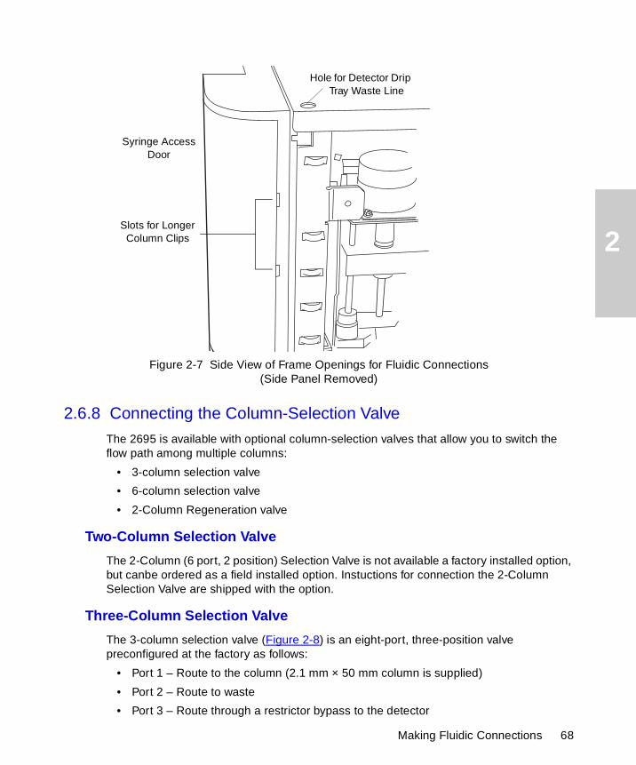
2
Figure 2-7 Side View of Frame Openings for Fluidic Connections(Side Panel Removed)
2.6.8 Connecting the Column-Selection Valve
The 2695 is available with optional column-selection valves that allow you to switch the flow path among multiple columns:
• 3-column selection valve
• 6-column selection valve
• 2-Column Regeneration valve
Two-Column Selection Valve
The 2-Column (6 port, 2 position) Selection Valve is not available a factory installed option, but canbe ordered as a field installed option. Instuctions for connection the 2-Column Selection Valve are shipped with the option.
Three-Column Selection Valve
The 3-column selection valve (Figure 2-8) is an eight-port, three-position valve preconfigured at the factory as follows:
• Port 1 – Route to the column (2.1 mm × 50 mm column is supplied)
• Port 2 – Route to waste
• Port 3 – Route through a restrictor bypass to the detector
Hole for Detector Drip Tray Waste Line
Slots for Longer Column Clips
Syringe AccessDoor
Making Fluidic Connections 68
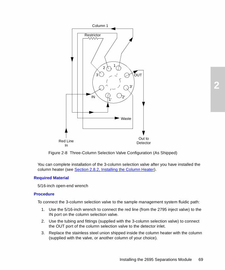
2
Figure 2-8 Three-Column Selection Valve Configuration (As Shipped)
You can complete installation of the 3-column selection valve after you have installed the column heater (see Section 2.8.2, Installing the Column Heater).
Required Material
5/16-inch open-end wrench
Procedure
To connect the 3-column selection valve to the sample management system fluidic path:
1. Use the 5/16-inch wrench to connect the red line (from the 2795 inject valve) to the IN port on the column selection valve.
2. Use the tubing and fittings (supplied with the 3-column selection valve) to connect the OUT port of the column selection valve to the detector inlet.
3. Replace the stainless steel union shipped inside the column heater with the column (supplied with the valve, or another column of your choice).
1′2′
3′
12
3
Column 1
Red LineIn
Out toDetector
Waste
IN
OUT
Restrictor
Installing the 2695 Separations Module 69
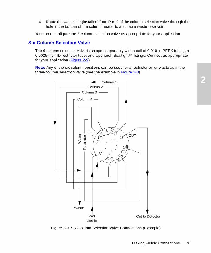
2
4. Route the waste line (installed) from Port 2 of the column selection valve through the hole in the bottom of the column heater to a suitable waste reservoir.
You can reconfigure the 3-column selection valve as appropriate for your application.
Six-Column Selection Valve
The 6-column selection valve is shipped separately with a coil of 0.010-in PEEK tubing, a 0.0025-inch ID restrictor tube, and Upchurch Sealtight™ fittings. Connect as appropriate for your application (Figure 2-9).
Note: Any of the six column positions can be used for a restrictor or for waste as in the three-column selection valve (see the example in Figure 2-8).
Figure 2-9 Six-Column Selection Valve Connections (Example)
1′ 2′ 3′
123
56
4′
5′
6′
4
IN
OUT
Column 1Column 2
Column 3
Column 4
Res
tric
tor
Red Line In
Out to Detector
Waste
Was
te
Making Fluidic Connections 70

2
Two-Column Regeneration Valve
The 2-column regeneration valve is shipped separately with a coil of 0.010-inch PEEK tubing, a 0.0025-inch ID restrictor tube, and Upchurch Sealtight™ fittings. Connect as appropriate for your application (see the example in Figure 2-10). Contact Waters Technical Service for more information.
Figure 2-10 Column Regeneration Valve Connections (Example)
2.6.9 Connecting the Detector
You can place the detector on either the top or the right-hand side of the Separations Module. If you place the detector on top of the Separations Module, be sure to install the drip tray using the procedure in Section 2.6.1, Installing the Detector Drip Tray.
Column B
Column A
OUT
Waste
Out to DetectorExternal Pump
IN
Red LineIn
1
2
34
56
7
8
910
Installing the 2695 Separations Module 71
2
To connect the detector:
1. Connect the outlet of the column to the inlet of the detector.
2. Connect a waste line from the detector outlet to a suitable waste container.
2.7 Signal Connections
The rear panel of the Separations Module (Figure 2-3) provides connection terminals and communication ports for operation with external devices.
The signal connections you need to make to your Separations Module depend on the:
• Operating mode you select for the Separations Module (System Controller, No Interaction, Remote, or Operate Gradient by Event In mode)
• Types of instruments that make up your HPLC system
This section describes the input/output (I/O) and digital signal connections that you can make from the terminal strips, RS-232 connectors, and IEEE-488 bus connector on the rear panel of the Separations Module.
Use Figure 2-11 as an overview of the steps involved in making signal connections to the Separations Module.
STOPAttention: To avoid spill damage, use a drip tray below the fluid connections on the detector.
Signal Connections 72
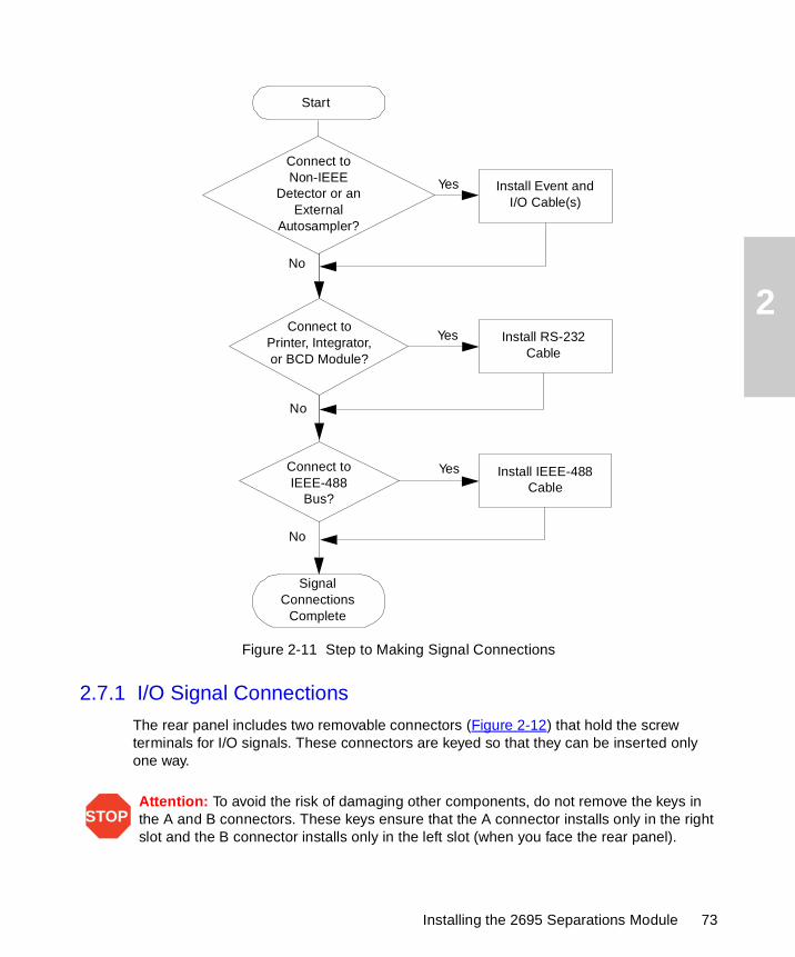
2
Figure 2-11 Step to Making Signal Connections
2.7.1 I/O Signal Connections
The rear panel includes two removable connectors (Figure 2-12) that hold the screw terminals for I/O signals. These connectors are keyed so that they can be inserted only one way.
STOPAttention: To avoid the risk of damaging other components, do not remove the keys in the A and B connectors. These keys ensure that the A connector installs only in the right slot and the B connector installs only in the left slot (when you face the rear panel).
No
Yes
Start
Signal Connections
Complete
No
YesConnect to
Printer, Integrator, or BCD Module?
Install RS-232 Cable
No
Yes
Connect to Non-IEEE
Detector or an External
Autosampler?
Install Event and I/O Cable(s)
Connect to IEEE-488
Bus?
Install IEEE-488 Cable
Installing the 2695 Separations Module 73
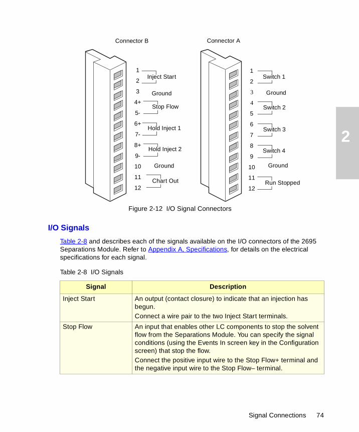
2
Figure 2-12 I/O Signal Connectors
I/O Signals
Table 2-8 and describes each of the signals available on the I/O connectors of the 2695 Separations Module. Refer to Appendix A, Specifications, for details on the electrical specifications for each signal.
Table 2-8 I/O Signals
Signal Description
Inject Start An output (contact closure) to indicate that an injection has begun.Connect a wire pair to the two Inject Start terminals.
Stop Flow An input that enables other LC components to stop the solvent flow from the Separations Module. You can specify the signal conditions (using the Events In screen key in the Configuration screen) that stop the flow. Connect the positive input wire to the Stop Flow+ terminal and the negative input wire to the Stop Flow– terminal.
Connector AConnector B
Inject Start
Stop Flow
Hold Inject 1
Hold Inject 2
Chart Out
Ground
Ground
Switch 1
Switch 2
Ground
Switch 3
Switch 4
Ground
Run Stopped
1
2
3
4+
5-
6+
7-
8+
9-
10
11
12
1
2
3
4
5
6
7
8
9
10
11
12
Signal Connections 74
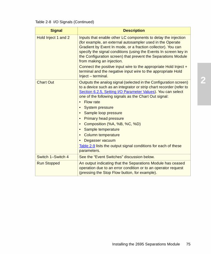
2
Hold Inject 1 and 2 Inputs that enable other LC components to delay the injection (for example, an external autosampler used in the Operate Gradient by Event In mode, or a fraction collector). You can specify the signal conditions (using the Events In screen key in the Configuration screen) that prevent the Separations Module from making an injection. Connect the positive input wire to the appropriate Hold Inject + terminal and the negative input wire to the appropriate Hold Inject – terminal.
Chart Out Outputs the analog signal (selected in the Configuration screen) to a device such as an integrator or strip chart recorder (refer to Section 6.2.5, Setting I/O Parameter Values). You can select one of the following signals as the Chart Out signal:• Flow rate• System pressure• Sample loop pressure• Primary head pressure• Composition (%A, %B, %C, %D)• Sample temperature• Column temperature• Degasser vacuumTable 2-9 lists the output signal conditions for each of these parameters.
Switch 1–Switch 4 See the “Event Switches” discussion below.
Run Stopped An output indicating that the Separations Module has ceased operation due to an error condition or to an operator request (pressing the Stop Flow button, for example).
Table 2-8 I/O Signals (Continued)
Signal Description
Installing the 2695 Separations Module 75
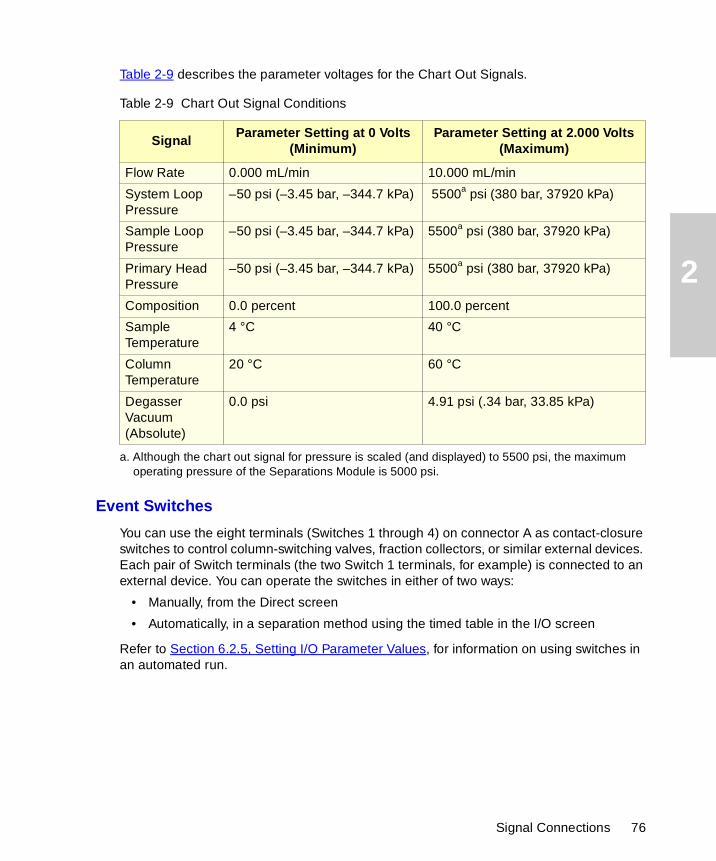
2
Table 2-9 describes the parameter voltages for the Chart Out Signals.
Event Switches
You can use the eight terminals (Switches 1 through 4) on connector A as contact-closure switches to control column-switching valves, fraction collectors, or similar external devices. Each pair of Switch terminals (the two Switch 1 terminals, for example) is connected to an external device. You can operate the switches in either of two ways:
• Manually, from the Direct screen
• Automatically, in a separation method using the timed table in the I/O screen
Refer to Section 6.2.5, Setting I/O Parameter Values, for information on using switches in an automated run.
Table 2-9 Chart Out Signal Conditions
SignalParameter Setting at 0 Volts
(Minimum)Parameter Setting at 2.000 Volts
(Maximum)
Flow Rate 0.000 mL/min 10.000 mL/min
System Loop Pressure
–50 psi (–3.45 bar, –344.7 kPa) 5500a psi (380 bar, 37920 kPa)
a. Although the chart out signal for pressure is scaled (and displayed) to 5500 psi, the maximum operating pressure of the Separations Module is 5000 psi.
Sample Loop Pressure
–50 psi (–3.45 bar, –344.7 kPa) 5500a psi (380 bar, 37920 kPa)
Primary Head Pressure
–50 psi (–3.45 bar, –344.7 kPa) 5500a psi (380 bar, 37920 kPa)
Composition 0.0 percent 100.0 percent
Sample Temperature
4 °C 40 °C
Column Temperature
20 °C 60 °C
Degasser Vacuum (Absolute)
0.0 psi 4.91 psi (.34 bar, 33.85 kPa)
Signal Connections 76
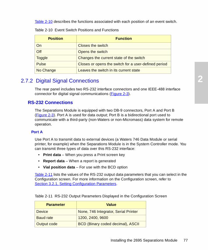
2
Table 2-10 describes the functions associated with each position of an event switch.
2.7.2 Digital Signal Connections
The rear panel includes two RS-232 interface connectors and one IEEE-488 interface connector for digital signal communications (Figure 2-3).
RS-232 Connections
The Separations Module is equipped with two DB-9 connectors, Port A and Port B (Figure 2-3). Port A is used for data output; Port B is a bidirectional port used to communicate with a third-party (non-Waters or non-Micromass) data system for remote operation.
Port A
Use Port A to transmit data to external devices (a Waters 746 Data Module or serial printer, for example) when the Separations Module is in the System Controller mode. You can transmit three types of data over this RS-232 interface:
• Print data – When you press a Print screen key
• Report data – When a report is generated
• Vial position data – For use with the BCD option
Table 2-11 lists the values of the RS-232 output data parameters that you can select in the Configuration screen. For more information on the Configuration screen, refer to Section 3.2.1, Setting Configuration Parameters.
Table 2-10 Event Switch Positions and Functions
Position Function
On Closes the switch
Off Opens the switch
Toggle Changes the current state of the switch
Pulse Closes or opens the switch for a user-defined period
No Change Leaves the switch in its current state
Table 2-11 RS-232 Output Parameters Displayed in the Configuration Screen
Parameter Value
Device None, 746 Integrator, Serial Printer
Baud rate 1200, 2400, 9600
Output code BCD (Binary coded decimal), ASCII
Installing the 2695 Separations Module 77
2
Port B
Use Port B to connect to a non-Waters or non-Micromass data system that uses RS-232 (ASCII) communications to control the Separations Module. To enable this port, you choose Controlled via RS232 (ASCII) in the Configuration screen. For more information on the Configuration screen, refer to Section 3.2.1, Setting Configuration Parameters.
IEEE-488 Connections
Use the IEEE-488 interface connector (Figure 2-3) to connect the Separations Module to IEEE-488 devices, such as the:
• Waters 996/2996 PDA Detector
• Waters 2487, 486, 2410, and 410 Detectors
• busLAC/E card in a Millennium Chromatography Manager workstation, a network LAC/E module (Millennium version 2.15 or higher), or a LAC/E32 Acquisition Server (Millennium32 version 3.00 or higher)
• General Purpose Instrument Board in a Micromass MassLynx computer
The IEEE-488 connector in the Separations Module mates with a standard IEEE-488 cable
Refer to Figure 1-5 for the signal connections (IEEE-488 and RS-232) in a typical HPLC system where the Separations Module functions as the System Controller. Refer to Figure 1-7 for the signal connections in a typical HPLC system with a Separations Module and Millennium Chromatography Manager.
Setting the IEEE-488 Address
Use the Configure screen to view or change the IEEE-488 address of the Separations Module. Refer to Section 3.2.2, Configuring the Operating Mode, for details on setting the IEEE-488 address.
2.8 Adding Hardware Options
Depending on your applications, you may want to install the following options on the Separations Module:
• Larger sample loop
• Column heater
• Larger or smaller syringe
STOPAttention: To avoid possible damage to components, power off all instruments connected to the IEEE-488 bus before you connect an IEEE-488 interface cable to an instrument.
Adding Hardware Options 78
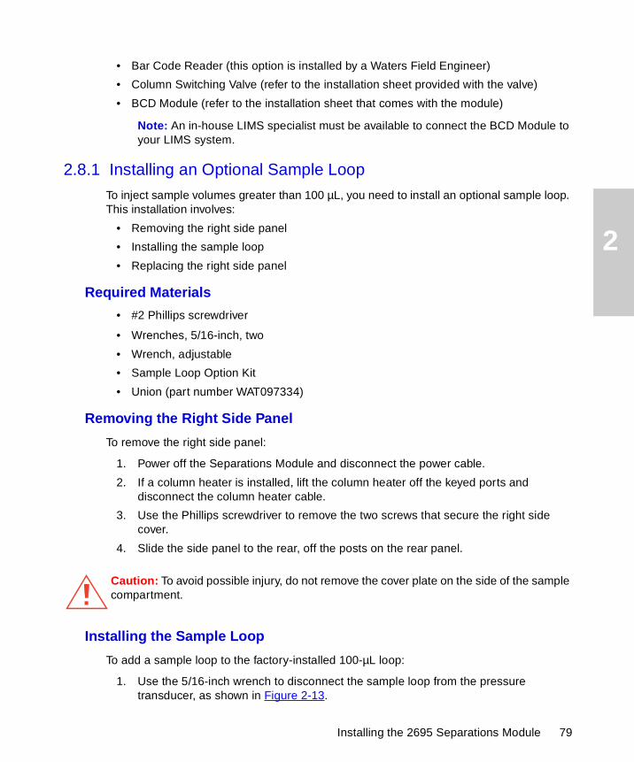
2
• Bar Code Reader (this option is installed by a Waters Field Engineer)
• Column Switching Valve (refer to the installation sheet provided with the valve)
• BCD Module (refer to the installation sheet that comes with the module)
Note: An in-house LIMS specialist must be available to connect the BCD Module to your LIMS system.
2.8.1 Installing an Optional Sample Loop
To inject sample volumes greater than 100 µL, you need to install an optional sample loop. This installation involves:
• Removing the right side panel
• Installing the sample loop
• Replacing the right side panel
Required Materials
• #2 Phillips screwdriver
• Wrenches, 5/16-inch, two
• Wrench, adjustable
• Sample Loop Option Kit
• Union (part number WAT097334)
Removing the Right Side Panel
To remove the right side panel:
1. Power off the Separations Module and disconnect the power cable.
2. If a column heater is installed, lift the column heater off the keyed ports and disconnect the column heater cable.
3. Use the Phillips screwdriver to remove the two screws that secure the right side cover.
4. Slide the side panel to the rear, off the posts on the rear panel.
Installing the Sample Loop
To add a sample loop to the factory-installed 100-µL loop:
1. Use the 5/16-inch wrench to disconnect the sample loop from the pressure transducer, as shown in Figure 2-13.
Caution: To avoid possible injury, do not remove the cover plate on the side of the sample compartment.
Installing the 2695 Separations Module 79

2
2. Connect the open end of the existing sample loop to one end of the union. Connect the other end of the union to the new sample loop.
3. Connect the open end of the new sample loop to the pressure transducer.
4. Use the wrenches to tighten the connections.
5. Connect the power cable and power on the Separations Module.
6. Enter the new sample loop volume in the Configuration screen (Section 3.2, Configuring the Separations Module).
7. Perform a purge and compression check to eliminate air bubbles and check for leaks. Refer to Section 3.4.1, Purging the Sample Management System, for the purge procedure.
To install a sample loop:
1. Use the 5/16-inch wrench to disconnect the sample loop from the pressure transducer and the needle drive mechanism, as shown in Figure 2-13.
2. Connect one end of the sample loop to the needle drive mechanism.
3. Connect the open end of the new sample loop to the pressure transducer.
4. Use the wrenches to tighten the connections.
5. Connect the power cable and power on the Separations Module.
6. Enter the new sample loop volume in the Configuration screen (Section 3.2, Configuring the Separations Module).
7. Perform a purge and compression check to eliminate air bubbles and check for leaks. Refer to Section 3.4.1, Purging the Sample Management System, for the purge procedure.
Figure 2-13 Disconnecting the Sample Loop
TP01365
Disconnect Here
Sample Loop Pressure
Transducer
Needle Mounting
Block
Adding Hardware Options 80
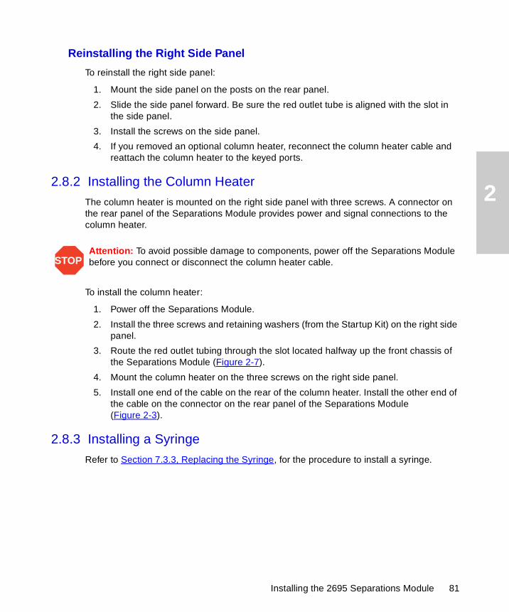
2
Reinstalling the Right Side Panel
To reinstall the right side panel:
1. Mount the side panel on the posts on the rear panel.
2. Slide the side panel forward. Be sure the red outlet tube is aligned with the slot in the side panel.
3. Install the screws on the side panel.
4. If you removed an optional column heater, reconnect the column heater cable and reattach the column heater to the keyed ports.
2.8.2 Installing the Column Heater
The column heater is mounted on the right side panel with three screws. A connector on the rear panel of the Separations Module provides power and signal connections to the column heater.
To install the column heater:
1. Power off the Separations Module.
2. Install the three screws and retaining washers (from the Startup Kit) on the right side panel.
3. Route the red outlet tubing through the slot located halfway up the front chassis of the Separations Module (Figure 2-7).
4. Mount the column heater on the three screws on the right side panel.
5. Install one end of the cable on the rear of the column heater. Install the other end of the cable on the connector on the rear panel of the Separations Module (Figure 2-3).
2.8.3 Installing a Syringe
Refer to Section 7.3.3, Replacing the Syringe, for the procedure to install a syringe.
STOPAttention: To avoid possible damage to components, power off the Separations Module before you connect or disconnect the column heater cable.
Installing the 2695 Separations Module 81
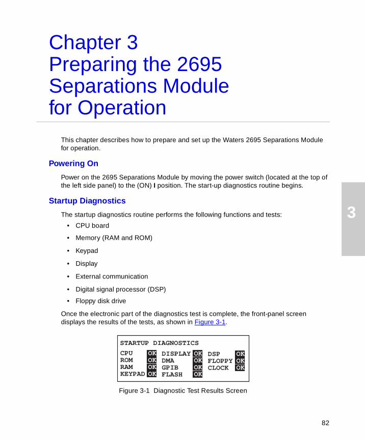
3
Chapter 3Preparing the 2695 Separations Module for Operation
This chapter describes how to prepare and set up the Waters 2695 Separations Module for operation.
Powering On
Power on the 2695 Separations Module by moving the power switch (located at the top of the left side panel) to the (ON) I position. The start-up diagnostics routine begins.
Startup Diagnostics
The startup diagnostics routine performs the following functions and tests:
• CPU board
• Memory (RAM and ROM)
• Keypad
• Display
• External communication
• Digital signal processor (DSP)
• Floppy disk drive
Once the electronic part of the diagnostics test is complete, the front-panel screen displays the results of the tests, as shown in Figure 3-1.
Figure 3-1 Diagnostic Test Results Screen
CPUROMRAMKEYPAD
DISPLAYDMAGPIBFLASH
DSPFLOPPYCLOCK
OKOK
OK
OK
OKOK
OK
OK
OKOK
OK
STARTUP DIAGNOSTICS
82
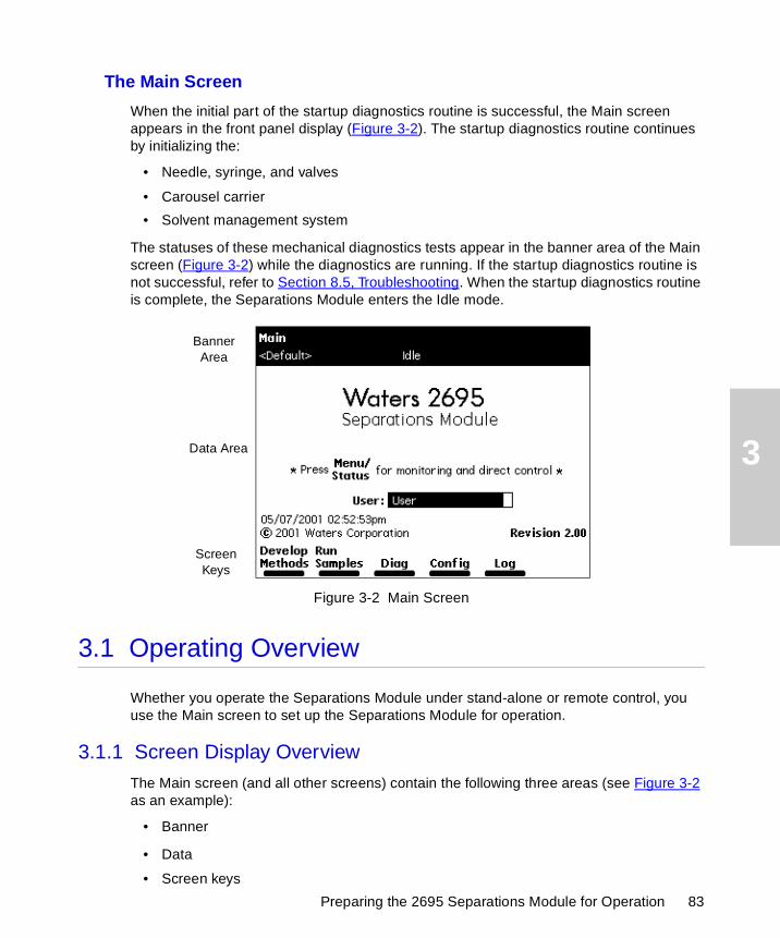
3
Preparing the 2695 Separations Module for Operation 83
The Main Screen
When the initial part of the startup diagnostics routine is successful, the Main screen appears in the front panel display (Figure 3-2). The startup diagnostics routine continues by initializing the:
• Needle, syringe, and valves
• Carousel carrier
• Solvent management system
The statuses of these mechanical diagnostics tests appear in the banner area of the Main screen (Figure 3-2) while the diagnostics are running. If the startup diagnostics routine is not successful, refer to Section 8.5, Troubleshooting. When the startup diagnostics routine is complete, the Separations Module enters the Idle mode.
Figure 3-2 Main Screen
3.1 Operating Overview
Whether you operate the Separations Module under stand-alone or remote control, you use the Main screen to set up the Separations Module for operation.
3.1.1 Screen Display Overview
The Main screen (and all other screens) contain the following three areas (see Figure 3-2 as an example):
• Banner
• Data
• Screen keys
Banner Area
Data Area
Screen Keys
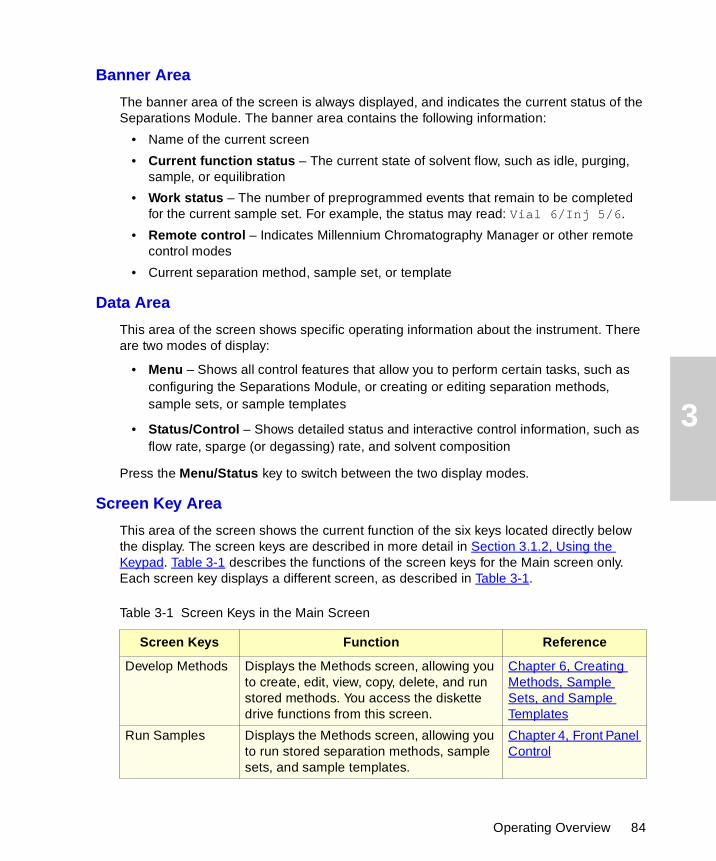
3
Banner Area
The banner area of the screen is always displayed, and indicates the current status of the Separations Module. The banner area contains the following information:
• Name of the current screen
• Current function status – The current state of solvent flow, such as idle, purging, sample, or equilibration
• Work status – The number of preprogrammed events that remain to be completed for the current sample set. For example, the status may read: Vial 6/Inj 5/6.
• Remote control – Indicates Millennium Chromatography Manager or other remote control modes
• Current separation method, sample set, or template
Data Area
This area of the screen shows specific operating information about the instrument. There are two modes of display:
• Menu – Shows all control features that allow you to perform certain tasks, such as configuring the Separations Module, or creating or editing separation methods, sample sets, or sample templates
• Status/Control – Shows detailed status and interactive control information, such as flow rate, sparge (or degassing) rate, and solvent composition
Press the Menu/Status key to switch between the two display modes.
Screen Key Area
This area of the screen shows the current function of the six keys located directly below the display. The screen keys are described in more detail in Section 3.1.2, Using the Keypad. Table 3-1 describes the functions of the screen keys for the Main screen only. Each screen key displays a different screen, as described in Table 3-1.
Table 3-1 Screen Keys in the Main Screen
Screen Keys Function Reference
Develop Methods Displays the Methods screen, allowing you to create, edit, view, copy, delete, and run stored methods. You access the diskette drive functions from this screen.
Chapter 6, Creating Methods, Sample Sets, and Sample Templates
Run Samples Displays the Methods screen, allowing you to run stored separation methods, sample sets, and sample templates.
Chapter 4, Front Panel Control
Operating Overview 84
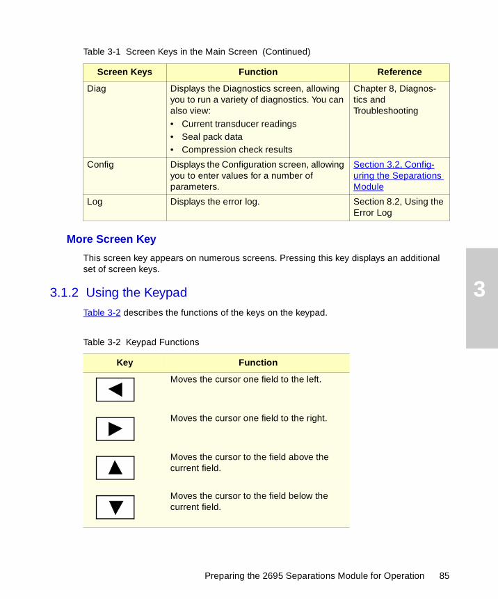
3
More Screen Key
This screen key appears on numerous screens. Pressing this key displays an additional set of screen keys.
3.1.2 Using the Keypad
Table 3-2 describes the functions of the keys on the keypad.
Diag Displays the Diagnostics screen, allowing you to run a variety of diagnostics. You can also view:• Current transducer readings• Seal pack data• Compression check results
Chapter 8, Diagnos-tics and Troubleshooting
Config Displays the Configuration screen, allowing you to enter values for a number of parameters.
Section 3.2, Config-uring the Separations Module
Log Displays the error log. Section 8.2, Using the Error Log
Table 3-2 Keypad Functions
Key Function
Moves the cursor one field to the left.
Moves the cursor one field to the right.
Moves the cursor to the field above the current field.
Moves the cursor to the field below the current field.
Table 3-1 Screen Keys in the Main Screen (Continued)
Screen Keys Function Reference
Preparing the 2695 Separations Module for Operation 85

3
Moves the cursor to the left-most field in the current row. Press twice to move the cursor to the first field in the screen.
Moves the cursor to the right-most field in the current row. Press twice to move the cursor to the last field in the screen.
Increases the display contrast.
Decreases the display contrast.
Displays a context-sensitive Help screen. Press again to display a general Help screen. To close the Help screen, press Exit or Clear.
Closes an open menu or dialog box and returns to the previous screen.
Clears the contents of the current field, or enters INIT or OFF in selected fields.
Stores the contents of the current field and advances the cursor to the next field in the screen.
Switches the display between the Menu mode and the Status/Control mode.
Immediately stops the flow of solvent and terminates the current function (sample processing, priming, purging, and so on). Pressing this key also activates the Run Stopped output switch.
Table 3-2 Keypad Functions (Continued)
Key Function
?
Exit
Clear
Enter
Menu/Status
Stop Flow
Operating Overview 86

3
Entering Values in Parameter Fields
To enter parameter values:
1. Use the screen keys or the Menu/Status key to display the appropriate screen.
2. Use the arrow keys to select the parameter field you want to change.
3. When a diamond is displayed after the field name:
a. Press Enter to display a drop-down list.
b. Use the arrow keys to select the value you want, then press Enter.
4. When you need to enter data into a field:
• Use the numeric keys to enter a numeric value, then press Enter.
• Use the screen keys to enter alphabetic data, then press Enter. See the “Entering an Alphanumeric String” discussion below.
5. To select or deselect a check box:
a. Use the arrow keys to select the check box.
b. Press any numeric key to place an “X” in the box and activate the option.
c. Press any numeric key to clear the box and deactivate the option.
Entering an Alphanumeric String
When you select a field that requires an alphabetic entry, such as the user name or method name, each screen key is automatically labeled with a group of letters, as shown in Figure 3-3. Press the More key for additional selections, such as uppercase and lowercase letters, and for selected non-alphabetic characters. Press the appropriate numeric keys to enter numbers into the field.
Enters the corresponding number into the current field, selects the corresponding gradient curve (0 = curve 10), positions the cursor to the corresponding entry in a list (0 = tenth item).
Enters a decimal point, selects gradient curve 11, or serves as a separator for vial ranges. For example, to enter 2 through 5 in a vial field, press 2.5. Also positions the cursor to the last entry in a list.
Table 3-2 Keypad Functions (Continued)
Key Function
0
9
through
•
Preparing the 2695 Separations Module for Operation 87

3
Figure 3-3 Alphabetic Screen Keys
You can enter up to 30 characters in an alphanumeric field. To end and save an alphanumeric entry, press Enter.
Figure 3-4 illustrates the procedure for entering alphabetic data in a text field.
Operating Overview 88
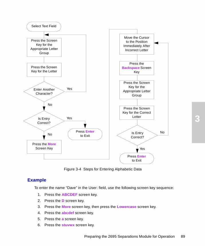
3
Figure 3-4 Steps for Entering Alphabetic Data
Example
To enter the name “Dave” in the User: field, use the following screen key sequence:
1. Press the ABCDEF screen key.
2. Press the D screen key.
3. Press the More screen key, then press the Lowercase screen key.
4. Press the abcdef screen key.
5. Press the a screen key.
6. Press the stuvwx screen key.
Select Text Field
Yes
No
Yes
NoPress Enter
to Exit
Press Enter to Exit
Yes
No
Press the Screen Key for the
Appropriate Letter Group
Press the Screen Key for the Letter
Enter Another Character?
Is EntryCorrect?
Press the MoreScreen Key
Press the Backspace Screen
Key
Press the Screen Key for the
Appropriate Letter Group
Press the Screen Key for the Correct
Letter
Is EntryCorrect?
Move the Cursor to the Position
Immediately AfterIncorrect Letter
Preparing the 2695 Separations Module for Operation 89
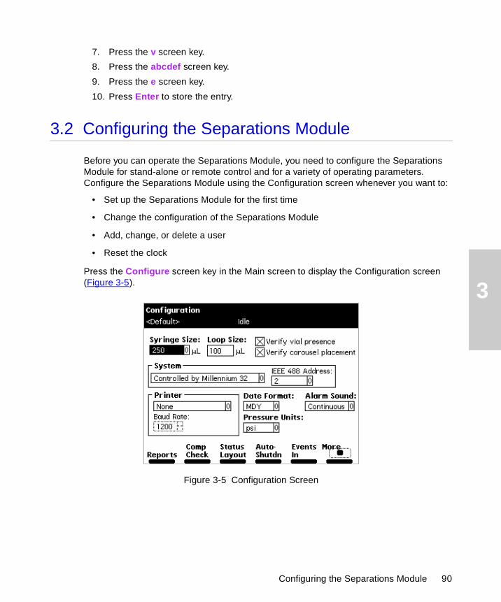
3
7. Press the v screen key.
8. Press the abcdef screen key.
9. Press the e screen key.
10. Press Enter to store the entry.
3.2 Configuring the Separations Module
Before you can operate the Separations Module, you need to configure the Separations Module for stand-alone or remote control and for a variety of operating parameters. Configure the Separations Module using the Configuration screen whenever you want to:
• Set up the Separations Module for the first time
• Change the configuration of the Separations Module
• Add, change, or delete a user
• Reset the clock
Press the Configure screen key in the Main screen to display the Configuration screen (Figure 3-5).
Figure 3-5 Configuration Screen
Configuring the Separations Module 90
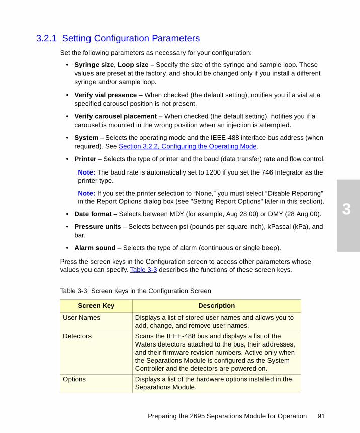
3
3.2.1 Setting Configuration Parameters
Set the following parameters as necessary for your configuration:
• Syringe size, Loop size – Specify the size of the syringe and sample loop. These values are preset at the factory, and should be changed only if you install a different syringe and/or sample loop.
• Verify vial presence – When checked (the default setting), notifies you if a vial at a specified carousel position is not present.
• Verify carousel placement – When checked (the default setting), notifies you if a carousel is mounted in the wrong position when an injection is attempted.
• System – Selects the operating mode and the IEEE-488 interface bus address (when required). See Section 3.2.2, Configuring the Operating Mode.
• Printer – Selects the type of printer and the baud (data transfer) rate and flow control.
Note: The baud rate is automatically set to 1200 if you set the 746 Integrator as the printer type.
Note: If you set the printer selection to “None,” you must select “Disable Reporting” in the Report Options dialog box (see "Setting Report Options" later in this section).
• Date format – Selects between MDY (for example, Aug 28 00) or DMY (28 Aug 00).
• Pressure units – Selects between psi (pounds per square inch), kPascal (kPa), and bar.
• Alarm sound – Selects the type of alarm (continuous or single beep).
Press the screen keys in the Configuration screen to access other parameters whose values you can specify. Table 3-3 describes the functions of these screen keys.
Table 3-3 Screen Keys in the Configuration Screen
Screen Key Description
User Names Displays a list of stored user names and allows you to add, change, and remove user names.
Detectors Scans the IEEE-488 bus and displays a list of the Waters detectors attached to the bus, their addresses, and their firmware revision numbers. Active only when the Separations Module is configured as the System Controller and the detectors are powered on.
Options Displays a list of the hardware options installed in the Separations Module.
Preparing the 2695 Separations Module for Operation 91
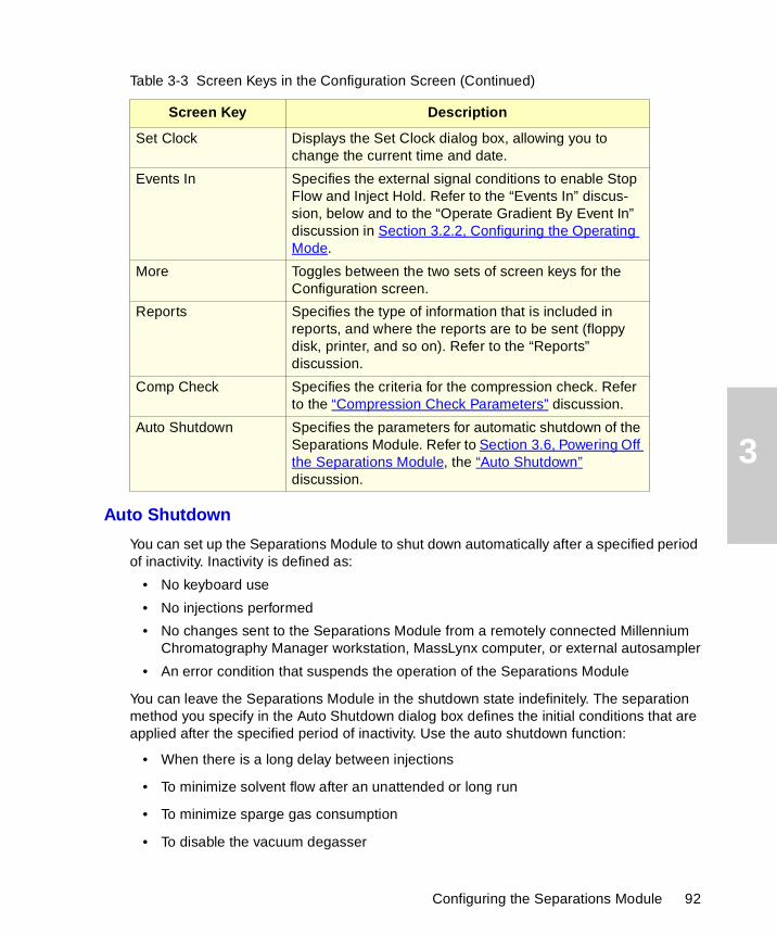
3
Auto Shutdown
You can set up the Separations Module to shut down automatically after a specified period of inactivity. Inactivity is defined as:
• No keyboard use
• No injections performed
• No changes sent to the Separations Module from a remotely connected Millennium Chromatography Manager workstation, MassLynx computer, or external autosampler
• An error condition that suspends the operation of the Separations Module
You can leave the Separations Module in the shutdown state indefinitely. The separation method you specify in the Auto Shutdown dialog box defines the initial conditions that are applied after the specified period of inactivity. Use the auto shutdown function:
• When there is a long delay between injections
• To minimize solvent flow after an unattended or long run
• To minimize sparge gas consumption
• To disable the vacuum degasser
Set Clock Displays the Set Clock dialog box, allowing you to change the current time and date.
Events In Specifies the external signal conditions to enable Stop Flow and Inject Hold. Refer to the “Events In” discus-sion, below and to the “Operate Gradient By Event In” discussion in Section 3.2.2, Configuring the Operating Mode.
More Toggles between the two sets of screen keys for the Configuration screen.
Reports Specifies the type of information that is included in reports, and where the reports are to be sent (floppy disk, printer, and so on). Refer to the “Reports” discussion.
Comp Check Specifies the criteria for the compression check. Refer to the “Compression Check Parameters” discussion.
Auto Shutdown Specifies the parameters for automatic shutdown of the Separations Module. Refer to Section 3.6, Powering Off the Separations Module, the “Auto Shutdown” discussion.
Table 3-3 Screen Keys in the Configuration Screen (Continued)
Screen Key Description
Configuring the Separations Module 92
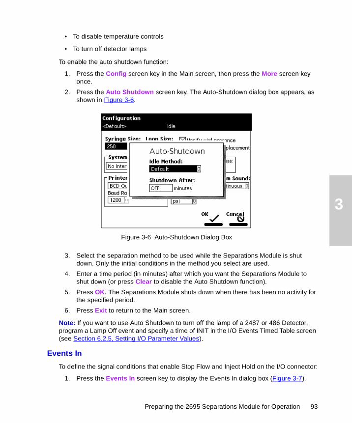
3
• To disable temperature controls
• To turn off detector lamps
To enable the auto shutdown function:
1. Press the Config screen key in the Main screen, then press the More screen key once.
2. Press the Auto Shutdown screen key. The Auto-Shutdown dialog box appears, as shown in Figure 3-6.
Figure 3-6 Auto-Shutdown Dialog Box
3. Select the separation method to be used while the Separations Module is shut down. Only the initial conditions in the method you select are used.
4. Enter a time period (in minutes) after which you want the Separations Module to shut down (or press Clear to disable the Auto Shutdown function).
5. Press OK. The Separations Module shuts down when there has been no activity for the specified period.
6. Press Exit to return to the Main screen.
Note: If you want to use Auto Shutdown to turn off the lamp of a 2487 or 486 Detector, program a Lamp Off event and specify a time of INIT in the I/O Events Timed Table screen (see Section 6.2.5, Setting I/O Parameter Values).
Events In
To define the signal conditions that enable Stop Flow and Inject Hold on the I/O connector:
1. Press the Events In screen key to display the Events In dialog box (Figure 3-7).
Preparing the 2695 Separations Module for Operation 93
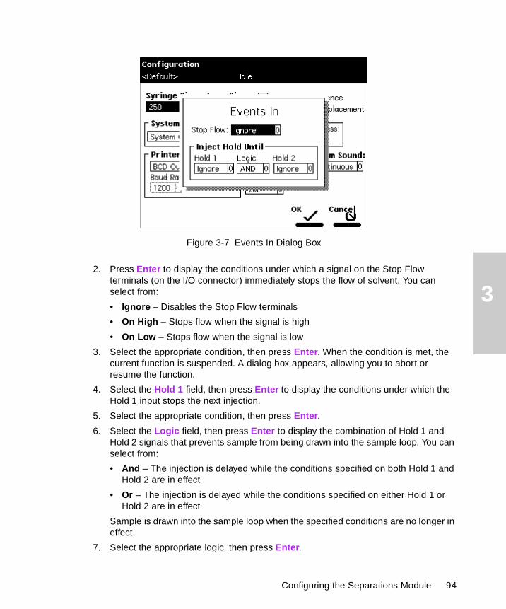
3
Figure 3-7 Events In Dialog Box
2. Press Enter to display the conditions under which a signal on the Stop Flow terminals (on the I/O connector) immediately stops the flow of solvent. You can select from:
• Ignore – Disables the Stop Flow terminals
• On High – Stops flow when the signal is high
• On Low – Stops flow when the signal is low
3. Select the appropriate condition, then press Enter. When the condition is met, the current function is suspended. A dialog box appears, allowing you to abort or resume the function.
4. Select the Hold 1 field, then press Enter to display the conditions under which the Hold 1 input stops the next injection.
5. Select the appropriate condition, then press Enter.
6. Select the Logic field, then press Enter to display the combination of Hold 1 and Hold 2 signals that prevents sample from being drawn into the sample loop. You can select from:
• And – The injection is delayed while the conditions specified on both Hold 1 and Hold 2 are in effect
• Or – The injection is delayed while the conditions specified on either Hold 1 or Hold 2 are in effect
Sample is drawn into the sample loop when the specified conditions are no longer in effect.
7. Select the appropriate logic, then press Enter.
Configuring the Separations Module 94
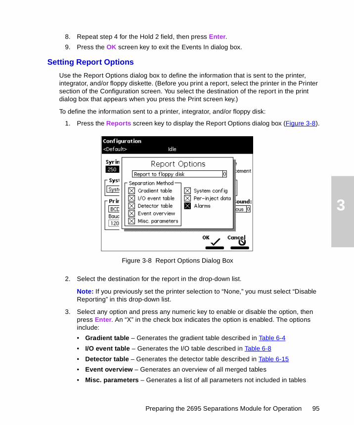
3
8. Repeat step 4 for the Hold 2 field, then press Enter.
9. Press the OK screen key to exit the Events In dialog box.
Setting Report Options
Use the Report Options dialog box to define the information that is sent to the printer, integrator, and/or floppy diskette. (Before you print a report, select the printer in the Printer section of the Configuration screen. You select the destination of the report in the print dialog box that appears when you press the Print screen key.)
To define the information sent to a printer, integrator, and/or floppy disk:
1. Press the Reports screen key to display the Report Options dialog box (Figure 3-8).
Figure 3-8 Report Options Dialog Box
2. Select the destination for the report in the drop-down list.
Note: If you previously set the printer selection to “None,” you must select “Disable Reporting” in this drop-down list.
3. Select any option and press any numeric key to enable or disable the option, then press Enter. An “X” in the check box indicates the option is enabled. The options include:
• Gradient table – Generates the gradient table described in Table 6-4
• I/O event table – Generates the I/O table described in Table 6-8
• Detector table – Generates the detector table described in Table 6-15
• Event overview – Generates an overview of all merged tables
• Misc. parameters – Generates a list of all parameters not included in tables
Preparing the 2695 Separations Module for Operation 95
3
• System config – Generates a list of the instrument configuration parameters
• Per-inject data – Generates a list of the minimum, maximum, and average values for temperature and pressure, the time and date of each injection, the bar code number, and so on
• Alarms – Generates a list of the error conditions that occurred during each injection
4. Press the OK screen key to exit the Report Options dialog box.
5. Press Exit to return to the Main screen.
Figure 3-9 is an example of a report with all options enabled.
Configuring the Separations Module 96
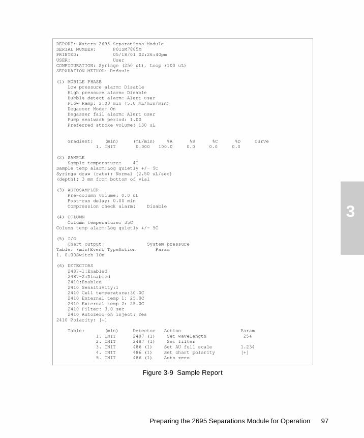
3
Figure 3-9 Sample Report
REPORT: Waters 2695 Separations ModuleSERIAL NUMBER: F01SM7885MPRINTED: 05/18/01 02:26:40pmUSER: UserCONFIGURATION: Syringe (250 uL), Loop (100 uL)SEPARATION METHOD: Default
(1) MOBILE PHASE Low pressure alarm: Disable High pressure alarm: Disable Bubble detect alarm: Alert user Flow Ramp: 2.00 min (5.0 mL/min/min) Degasser Mode: On Degasser fail alarm: Alert user Pump sealwash period: 1.00 Preferred stroke volume: 130 uL
Gradient: (min) (mL/min) %A %B %C %D Curve 1. INIT 0.000 100.0 0.0 0.0 0.0
(2) SAMPLE Sample temperature: 4CSample temp alarm:Log quietly +/- 5CSyringe draw (rate): Normal (2.50 uL/sec)(depth): 3 mm from bottom of vial
(3) AUTOSAMPLER Pre-column volume: 0.0 uL Post-run delay: 0.00 min Compression check alarm: Disable
(4) COLUMN Column temperature: 35CColumn temp alarm:Log quietly +/- 5C
(5) I/O Chart output: System pressureTable: (min)Event TypeAction Param 1. 0.00Switch 1On
(6) DETECTORS 2487-1:Enabled 2487-2:Disabled 2410:Enabled 2410 Sensitivity:1 2410 Cell temperature:30.0C 2410 External temp 1: 25.0C 2410 External temp 2: 25.0C 2410 Filter: 3.0 sec 2410 Autozero on inject: Yes2410 Polarity: [+] Table: (min) Detector Action Param 1. INIT 2487 (1) Set wavelength 254 2. INIT 2487 (1) Set filter 3. INIT 486 (1) Set AU full scale 1.234 4. INIT 486 (1) Set chart polarity [+] 5. INIT 486 (1) Auto zero
Preparing the 2695 Separations Module for Operation 97
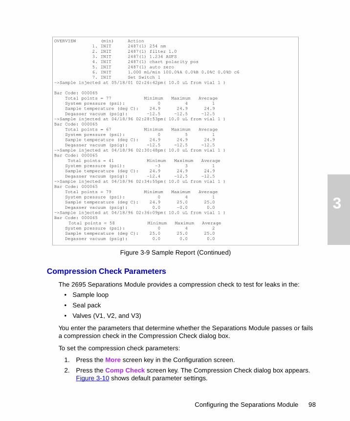
3
Figure 3-9 Sample Report (Continued)
Compression Check Parameters
The 2695 Separations Module provides a compression check to test for leaks in the:
• Sample loop
• Seal pack
• Valves (V1, V2, and V3)
You enter the parameters that determine whether the Separations Module passes or fails a compression check in the Compression Check dialog box.
To set the compression check parameters:
1. Press the More screen key in the Configuration screen.
2. Press the Comp Check screen key. The Compression Check dialog box appears. Figure 3-10 shows default parameter settings.
OVERVIEW (min) Action 1. INIT 2487(1) 254 nm 2. INIT 2487(1) filter 1.0 3. INIT 2487(1) 1.234 AUFS 4. INIT 2487(1) chart polarity pos 5. INIT 2487(1) auto zero 6. INIT 1.000 mL/min 100.0%A 0.0%B 0.0%C 0.0%D c6 7. INIT Set Switch 1->Sample injected at 05/18/01 02:26:42pm( 10.0 uL from vial 1 )
Bar Code: 000065 Total points = 77 Minimum Maximum Average System pressure (psi): 0 4 1 Sample temperature (deg C): 24.9 24.9 24.9 Degasser vacuum (psig): -12.5 -12.5 -12.5->Sample injected at 04/18/96 02:28:53pm( 10.0 uL from vial 1 )Bar Code: 000065 Total points = 67 Minimum Maximum Average System pressure (psi): 0 5 1 Sample temperature (deg C): 24.9 24.9 24.9 Degasser vacuum (psig): -12.5 -12.5 -12.5->Sample injected at 04/18/96 02:30:48pm( 10.0 uL from vial 1 )Bar Code: 000065
Total points = 41 Minimum Maximum Average System pressure (psi): -3 3 1 Sample temperature (deg C): 24.9 24.9 24.9 Degasser vacuum (psig): -12.4 -12.5 -12.5->Sample injected at 04/18/96 02:34:55pm( 10.0 uL from vial 1 )Bar Code: 000065 Total points = 79 Minimum Maximum Average System pressure (psi): 0 4 1 Sample temperature (deg C): 24.9 25.0 25.0 Degasser vacuum (psig): 0.0 -0.0 0.0->Sample injected at 04/18/96 02:36:09pm( 10.0 uL from vial 1 )Bar Code: 000065
Total points = 58 Minimum Maximum Average System pressure (psi): 0 4 2 Sample temperature (deg C): 25.0 25.0 25.0 Degasser vacuum (psig): 0.0 0.0 0.0
Configuring the Separations Module 98
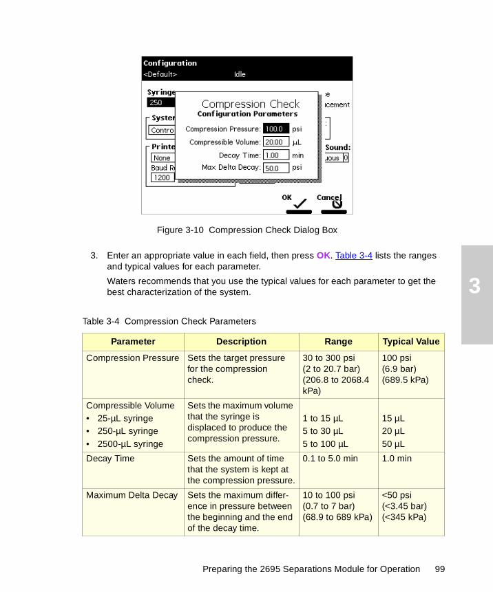
3
Figure 3-10 Compression Check Dialog Box
3. Enter an appropriate value in each field, then press OK. Table 3-4 lists the ranges and typical values for each parameter.
Waters recommends that you use the typical values for each parameter to get the best characterization of the system.
Table 3-4 Compression Check Parameters
Parameter Description Range Typical Value
Compression Pressure Sets the target pressure for the compression check.
30 to 300 psi (2 to 20.7 bar)(206.8 to 2068.4 kPa)
100 psi (6.9 bar)(689.5 kPa)
Compressible Volume• 25-µL syringe• 250-µL syringe• 2500-µL syringe
Sets the maximum volume that the syringe is displaced to produce the compression pressure.
1 to 15 µL5 to 30 µL5 to 100 µL
15 µL20 µL50 µL
Decay Time Sets the amount of time that the system is kept at the compression pressure.
0.1 to 5.0 min 1.0 min
Maximum Delta Decay Sets the maximum differ-ence in pressure between the beginning and the end of the decay time.
10 to 100 psi(0.7 to 7 bar)(68.9 to 689 kPa)
<50 psi(<3.45 bar)(<345 kPa)
Preparing the 2695 Separations Module for Operation 99

3
3.2.2 Configuring the Operating Mode
Use the System field in the Configuration screen (Figure 3-5) to select one of eight operating modes. When you select the System field and press Enter, the list of operating modes is displayed (Figure 3-11).
Figure 3-11 Configuring the Operating Mode
• No Interaction – Use for stand-alone operation.
• System Controller – Use for stand-alone operation when controlling Waters detectors over the IEEE-488 interface.
• Controlled by Millennium32 – Use when Millennium32 Chromatography Manager, Version 3.2 or higher, controls the HPLC system.
• Controlled by MassLynx – Use to control the Separations Module by Micromass MassLynx software (Version 3.5 or higher) over the IEEE-488 cable interface.
• Controlled by Millennium 2.xx – Use when the Millennium Chromatography Manager, Version 2.xx, controls the HPLC system.
• Operate Gradient by Event In – Use when an autosampler (external to the Separations Module) initiates a chromatographic run by contact closure.
• Controlled via RS232 (ASCII) – Use when a non-Waters or non-Micromass data system controls the Separations Module by RS-232 communications, using ASCII protocol, as specified by the data system.
• Controlled via RS232 (binary) – Use when a non-Waters or non-Micromass data system controls the Separations Module by RS-232 communications, using binary protocol, as specified by the data system.
Configuring the Separations Module 100
3
No Interaction Mode
In this stand-alone mode, the Separations Module is not connected to the IEEE-488 interface bus. The Separations Module controls other non-IEEE devices in the HPLC system using the I/O connections on the rear panel. Refer to Section 2.7.1, I/O Signal Connections, for the procedure to make I/O connections. Use this mode if you want to suspend communications with a connected Millennium Chromatography Manager workstation and operate the Separations Module and the other HPLC system components from their front panels.
To set the Separations Module to the No Interaction mode:
1. Select the System field in the Configuration screen, then press Enter to display a list of operating modes.
2. Select No Interaction, then press Enter.
3. Press Exit.
System Controller Mode
In this stand-alone mode, the Separations Module controls up to three detector channels on the IEEE-488 bus. This can include two UV detector channels (Waters 2487 and/or 486 Tunable Absorbance Detectors) and one RI detector channel (Waters 2410 or 410 Differential Refractometer). Refer to Section 2.7.2, Digital Signal Connections, for information on IEEE-488 connections. You can also control other HPLC modules using the I/O connections. Refer to Section 2.7.1, I/O Signal Connections, for the information on I/O connections.
To set the Separations Module to the System Controller mode:
1. Select the System field in the Configuration screen, then press Enter to display the list of operating modes.
2. Select System Controller, then press Enter.
3. Press the Detectors screen key. A list of active devices (with their IEEE-488 interface bus addresses) appears.
a. Press the Scan screen key to update the list.
b. Press the OK screen key to return to the Configuration screen.
4. Press Exit. The Separations Module is ready to control Waters detectors using separation methods and sample sets.
Controlled by Millennium32 Mode
In this remote-control mode, a Millennium Chromatography Manager workstation running Millennium32 software controls the operation of your HPLC system using the IEEE-488 interface bus. Connect the IEEE-488 cable as described in Section 2.7.2, Digital Signal Connections.
Preparing the 2695 Separations Module for Operation 101
3
To set the Separations Module to the Controlled by Millennium32 mode:
1. Select the System field in the Configuration screen, then press Enter to display a list of operating modes.
2. Select Controlled by Millennium32, then press Enter. The IEEE-488 Address field is highlighted. Note that the 2695 Separations Module requires only one IEEE-488 address when controlled by Millennium32.
3. Press Enter to display a list of addresses.
4. Select an address that is unused by other chromatographic components connected to the Millennium Chromatography Manager workstation, then press Enter.
5. Press Exit. The Separations Module is ready to be controlled from the Millennium Chromatography Manager workstation.
Refer to Section 5.2, Making Automatic Runs Under Millennium Control, for details on making runs under Millennium control.
Controlled by MassLynx Mode
In this remote-control mode, Micromass MassLynx software (Version 3.5 or higher) controls the 2695 Separations Module (in 2690-emulation mode). MassLynx software is used with Micromass mass spectrometry (MS) detectors, using the IEEE-488 interface between the Micromass computer and the 2695 Separations Module.
To set the Separations Module to the Controlled by MassLynx mode:
1. Select the System field in the Configuration screen, then press Enter to display a list of operating modes.
2. Select Controlled by MassLynx, then press Enter. The IEEE 488 Address field is highlighted.
3. Press Enter to display a list of addresses.
4. Select an address that is unused by other chromatographic components connected to the Micromass computer, then press Enter.
5. Press Exit. The Separations Module is ready to be controlled from the MassLynx computer.
Refer to Section 5.3, Making Automatic Runs Under Micromass MassLynx Control, for details on making runs under MassLynx control.
Controlled by Millennium 2.xx Mode
In this remote-control mode, a Millennium Chromatography Manager workstation running Millennium 2.xx software controls the 2695 Separations Module (in 2690- emulation mode) using the IEEE-488 interface bus. Connect the IEEE-488 cable as described in Section 2.7.2, Digital Signal Connections.
Configuring the Separations Module 102
3
To set the Separations Module to the Controlled by Millennium 2.xx mode:
1. Select the System field in the Configuration screen, then press Enter to display a list of operating modes.
2. Select Controlled by Millennium 2.xx, then press Enter. The IEEE-488 Address field is highlighted.
3. Press Enter to display a list of address pairs.
4. Select an address pair that is unused by other chromatographic components connected to the Millennium Chromatography Manager, then press Enter.
5. Press Exit. The Separations Module is ready to be controlled from the Millennium Chromatography Manager workstation.
The 2690 Separations Module appears as two devices in the Millennium System view:
• The solvent and sample management systems – With an even address
• The optional sample heater/cooler – With an odd address
Refer to Section 5.2, Making Automatic Runs Under Millennium Control, for details on making runs under Millennium control.
Controlled by Operate Gradient by Event In Mode
In this mode, an external autosampler (a Waters 2700 Sample Manager, for example) initiates the start of the chromatographic run and performs the inject function (instead of the Separations Module). In this mode, the Separations Module has no control of IEEE-488 devices, but can control non-IEEE devices using the I/O connections on the rear panel. Refer to Section 2.7.1, I/O Signal Connections, for information on I/O connections.
To set the Separations Module to the Operate Gradient by Event In mode:
1. Select the System field in the Configuration screen, then press Enter to display a list of operating modes.
2. Select Operate Gradient by Event In, then press Enter.
3. Press the Events In screen key to display the Events In dialog box (Figure 3-7). For information on defining Events In conditions, refer to Section 3.2.1, Setting Configuration Parameters, the “Events In” discussion.
4. Set the Stop Flow field to the appropriate condition (Ignore, High, or Low), then press Enter.
• Choose Ignore if the Stop Flow I/O terminals of the Separations Module are not used.
• Choose High if the output connection from the external autosampler to the Stop Flow I/O terminals of the Separations Module changes to a high (more positive) TTL-level.
Preparing the 2695 Separations Module for Operation 103
3
• Choose Low if the output connection from the external autosampler to the Stop Flow I/O terminals of the Separations Module changes to a low (more negative) TTL-level.
5. Set the Hold 1 field to the appropriate condition (High or Low), then press Enter.
• Choose High if the output connection from the external autosampler to the Hold 1 Inject terminals of the Separations Module changes to a high (more positive) TTL-level to initiate a chromatographic run (and prevent an injection by the Separations Module).
• Choose Low if the output connection from the external autosampler to the Hold 1 Inject terminals of the Separations Module changes to a low (more negative) TTL-level to initiate a chromatographic run (and prevent an injection by the Separations Module).
Note: If you are configuring the Separations Module with a Waters 2700 Sample Manager, select Low.
6. Set the Logic field to Or, then press Enter.
7. Set the Hold 2 field to Ignore, then press Enter.
8. Press the OK screen key to save your selections and exit from the Events In dialog box.
Controlled via RS-232 (ASCII) or (Binary) Mode
In these remote-control modes, a non-Waters or non-Micromass data system (a mass spectrometry system, for example) controls the Separations Module using RS-232 ASCII or binary communications. The Separations Module disconnects from the IEEE-488 interface bus when either of these modes is selected. The Separations Module can control other non-IEEE devices in the HPLC system using the I/O connections on the rear panel. Refer to Section 2.7.1, I/O Signal Connections, for information on I/O connections.
To set the Separations Module to the Controlled via RS-232 (ASCII) or (Binary) mode:
1. Select the System field in the Configuration screen, then press Enter to display a list of operating modes.
2. Select Controlled via RS232 (ASCII) or Controlled via RS232 (Binary), then press Enter.
3. Press Exit. The Separations Module is ready to be controlled by a remote data system using RS-232 communications.
Note: If you experience repeated problems when using a third-party data system, reconfigure the Separations Module to No Interaction mode. If the problem persists, refer to the appropriate section of this guide. If the problem occurs when using a third-party data system, but not when the instrument is configured in No Interaction mode, contact the data system vendor.
Configuring the Separations Module 104
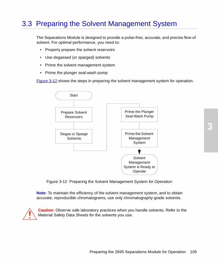
3
3.3 Preparing the Solvent Management System
The Separations Module is designed to provide a pulse-free, accurate, and precise flow of solvent. For optimal performance, you need to:
• Properly prepare the solvent reservoirs
• Use degassed (or sparged) solvents
• Prime the solvent management system
• Prime the plunger seal-wash pump
Figure 3-12 shows the steps in preparing the solvent management system for operation.
Figure 3-12 Preparing the Solvent Management System for Operation
Note: To maintain the efficiency of the solvent management system, and to obtain accurate, reproducible chromatograms, use only chromatography-grade solvents.
Caution: Observe safe laboratory practices when you handle solvents. Refer to the Material Safety Data Sheets for the solvents you use.
Start
Degas or Sparge Solvents
Prime the Solvent Management
System
Prime the Plunger Seal-Wash Pump
Solvent Management
System is Ready toOperate
Prepare Solvent Reservoirs
Preparing the 2695 Separations Module for Operation 105
3
3.3.1 Preparing Solvent Reservoirs
Choose solvent reservoirs that provide a snug fit for the reservoir caps supplied in the Startup Kit. Waters recommends 1-L reservoirs. Place the reservoirs in the solvent bottle tray and position the tray above the solvent management system components.
The solvent reservoir caps help maintain a continuously sparged environment in the reservoirs (for units equipped with helium sparge) and controls solvent evaporation. Each cap has three feather-edged holes to produce a positive seal around the solvent, sparge, and vent tubes.
Install the solvent, sparge, and vent lines as described in Section 2.6, Making Fluidic Connections.
3.3.2 Degassing Solvents
Sparging
For systems outfitted with the Sparge option, helium sparging reduces the total dissolved oxygen and nitrogen in the solvent reservoirs and maintains that condition during operation. Use an ultra-pure carrier (UPC) grade of helium to prevent solvent contamination. Refer to Section C.7, Mobile Phase Solvent Degassing, for more information on sparging.
Be sure the reservoirs and sparge tubing are set up according to the procedures in Section 2.6.3, Making Sparge Gas Connections.
Set the sparge rates in the Programmed Sparge screen described in Section 4.4.4, Programming the Sparge Cycles.
Inline Vacuum Degassing
Inline vacuum degassing reduces the total dissolved gas in the mobile phase. For more information on vacuum degassing, refer to Section 1.5, the “Degasser Considerations” discussion.
Note: For proper operation of the inline vacuum degasser, you must fill each vacuum chamber with solvent. Use the dry prime direct function to prime all solvent lines.
To control the inline vacuum degasser from the Status screen:
1. Press Menu/Status. The Status screen is displayed (Figure 3-13).
Preparing the Solvent Management System 106
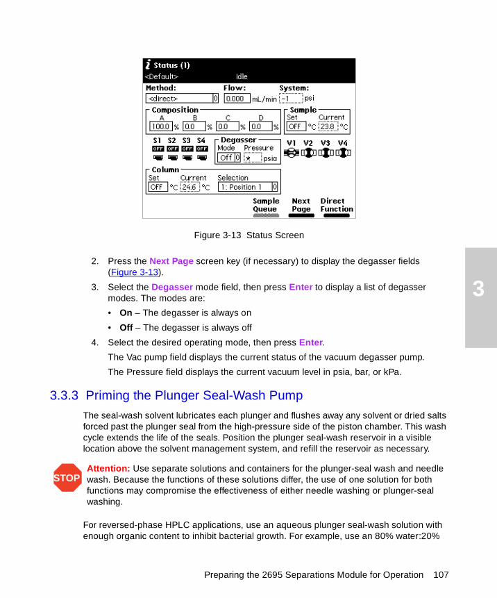
3
Figure 3-13 Status Screen
2. Press the Next Page screen key (if necessary) to display the degasser fields (Figure 3-13).
3. Select the Degasser mode field, then press Enter to display a list of degasser modes. The modes are:
• On – The degasser is always on
• Off – The degasser is always off
4. Select the desired operating mode, then press Enter.
The Vac pump field displays the current status of the vacuum degasser pump.
The Pressure field displays the current vacuum level in psia, bar, or kPa.
3.3.3 Priming the Plunger Seal-Wash Pump
The seal-wash solvent lubricates each plunger and flushes away any solvent or dried salts forced past the plunger seal from the high-pressure side of the piston chamber. This wash cycle extends the life of the seals. Position the plunger seal-wash reservoir in a visible location above the solvent management system, and refill the reservoir as necessary.
For reversed-phase HPLC applications, use an aqueous plunger seal-wash solution with enough organic content to inhibit bacterial growth. For example, use an 80% water:20%
STOPAttention: Use separate solutions and containers for the plunger-seal wash and needle wash. Because the functions of these solutions differ, the use of one solution for both functions may compromise the effectiveness of either needle washing or plunger-seal washing.
Preparing the 2695 Separations Module for Operation 107
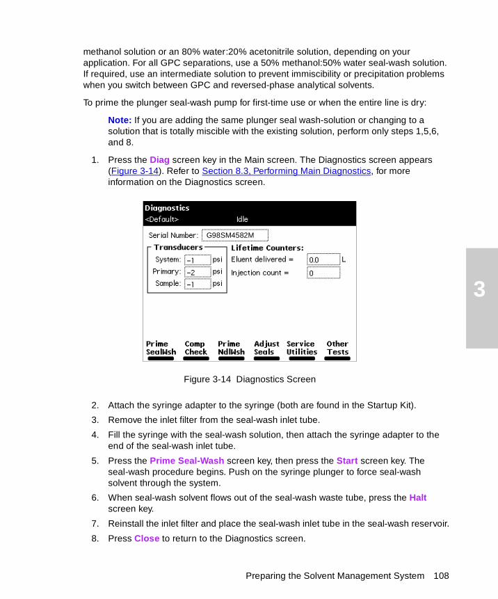
3
methanol solution or an 80% water:20% acetonitrile solution, depending on your application. For all GPC separations, use a 50% methanol:50% water seal-wash solution. If required, use an intermediate solution to prevent immiscibility or precipitation problems when you switch between GPC and reversed-phase analytical solvents.
To prime the plunger seal-wash pump for first-time use or when the entire line is dry:
Note: If you are adding the same plunger seal wash-solution or changing to a solution that is totally miscible with the existing solution, perform only steps 1,5,6, and 8.
1. Press the Diag screen key in the Main screen. The Diagnostics screen appears (Figure 3-14). Refer to Section 8.3, Performing Main Diagnostics, for more information on the Diagnostics screen.
Figure 3-14 Diagnostics Screen
2. Attach the syringe adapter to the syringe (both are found in the Startup Kit).
3. Remove the inlet filter from the seal-wash inlet tube.
4. Fill the syringe with the seal-wash solution, then attach the syringe adapter to the end of the seal-wash inlet tube.
5. Press the Prime Seal-Wash screen key, then press the Start screen key. The seal-wash procedure begins. Push on the syringe plunger to force seal-wash solvent through the system.
6. When seal-wash solvent flows out of the seal-wash waste tube, press the Halt screen key.
7. Reinstall the inlet filter and place the seal-wash inlet tube in the seal-wash reservoir.
8. Press Close to return to the Diagnostics screen.
G98SM4582M
Preparing the Solvent Management System 108
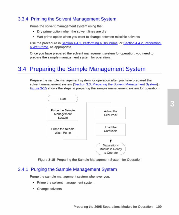
3
3.3.4 Priming the Solvent Management System
Prime the solvent management system using the:
• Dry prime option when the solvent lines are dry
• Wet prime option when you want to change between miscible solvents
Use the procedure in Section 4.4.1, Performing a Dry Prime, or Section 4.4.2, Performing a Wet Prime, as appropriate.
Once you have prepared the solvent management system for operation, you need to prepare the sample management system for operation.
3.4 Preparing the Sample Management System
Prepare the sample management system for operation after you have prepared the solvent management system (Section 3.3, Preparing the Solvent Management System). Figure 3-15 shows the steps in preparing the sample management system for operation.
Figure 3-15 Preparing the Sample Management System for Operation
3.4.1 Purging the Sample Management System
Purge the sample management system whenever you:
• Prime the solvent management system
• Change solvents
Start
Purge the Sample Management
System
Adjust the Seal Pack
Prime the Needle Wash Pump
Separations Module is Ready
to Operate
Load theCarousels
Preparing the 2695 Separations Module for Operation 109

3
• See bubbles in the syringe
• Start using the Separations Module at the beginning of each day
To purge the sample management system:
1. In the Main screen, press Menu/Status to display the Status screen.
2. Enter the appropriate solvent composition in the Composition fields.
3. Press Direct Functions to display the Direct Functions menu.
4. Select Purge Injector, then press Enter. The Purge Injector dialog box appears.
5. Enter the number of sample loop volumes in the Sample Loop Volumes field (use the default value of 6.0 volumes), then press Enter. The solvent management system ramps up to a predetermined flow rate to flush the sample loop with the selected volume.
6. Leave the Compression Check check box blank the first time you start up the system to prevent a compression test from occurring. The Separations Module does not allow a compression test before the seal pack is adjusted.
7. Press OK. The purge cycle begins.
3.4.2 Priming the Needle-Wash Pump
The needle-wash pump flushes the needle in the sample management system, preventing carryover of sample between injections. The needle-wash also extends the life of the injector seals by removing buffered mobile phase and sample from the needle.
Selecting a Needle-Wash Solvent
Use a needle-wash solvent based on the sample and mobile phase chemistries, making sure all solutions/buffers are miscible and soluble.
A gradient separation typically involves the initial use of a weak solvent combination, whereas final conditions usually have a combination of stronger solvents. In general, it is best to choose a needle-wash solvent similar to final gradient conditions. For example, in a separation with an initial gradient of 80% water:20% methanol and a final gradient of 10% water:90% methanol, an effective needle-wash solvent would be 20% water:80% methanol.
The choice of a needle-wash solvent similar, but not equivalent, to final gradient composition ensures solubility of early eluting peaks. When sample solubility in the mobile phase is pH-dependant, choose a needle-wash solution that is similarly pH- adjusted. If
STOPAttention: To avoid precipitating salts in the Separations Module, use an intermediate solvent such as water when you change from buffers to high-organic-content solvents.
Preparing the Sample Management System 110
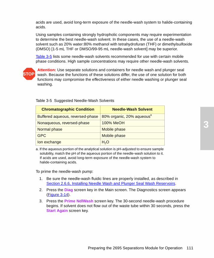
3
acids are used, avoid long-term exposure of the needle-wash system to halide-containing acids.
Using samples containing strongly hydropholic components may require experimentation to determine the best needle-wash solvent. In these cases, the use of a needle-wash solvent such as 20% water:80% methanol with tetrahydrofuran (THF) or dimethylsulfoxide (DMSO) [1-5 mL THF or DMSO/99-95 mL needle-wash solvent] may be superior.
Table 3-5 lists some needle-wash solvents recommended for use with certain mobile phase conditions. High sample concentrations may require other needle-wash solvents.
To prime the needle-wash pump:
1. Be sure the needle-wash fluidic lines are properly installed, as described in Section 2.6.6, Installing Needle Wash and Plunger Seal Wash Reservoirs.
2. Press the Diag screen key in the Main screen. The Diagnostics screen appears (Figure 3-14).
3. Press the Prime NdlWash screen key. The 30-second needle-wash procedure begins. If solvent does not flow out of the waste tube within 30 seconds, press the Start Again screen key.
STOPAttention: Use separate solutions and containers for needle wash and plunger seal wash. Because the functions of these solutions differ, the use of one solution for both functions may compromise the effectiveness of either needle washing or plunger seal washing.
Table 3-5 Suggested Needle-Wash Solvents
Chromatographic Condition Needle-Wash Solvent
Buffered aqueous, reversed-phase 80% organic, 20% aqueousa
a. If the aqueous portion of the analytical solution is pH-adjusted to ensure sample solubility, match the pH of the aqueous portion of the needle-wash solution to it. If acids are used, avoid long-term exposure of the needle-wash system to halide-containing acids.
Nonaqueous, reversed-phase 100% MeOH
Normal phase Mobile phase
GPC Mobile phase
Ion exchange H2O
Preparing the 2695 Separations Module for Operation 111
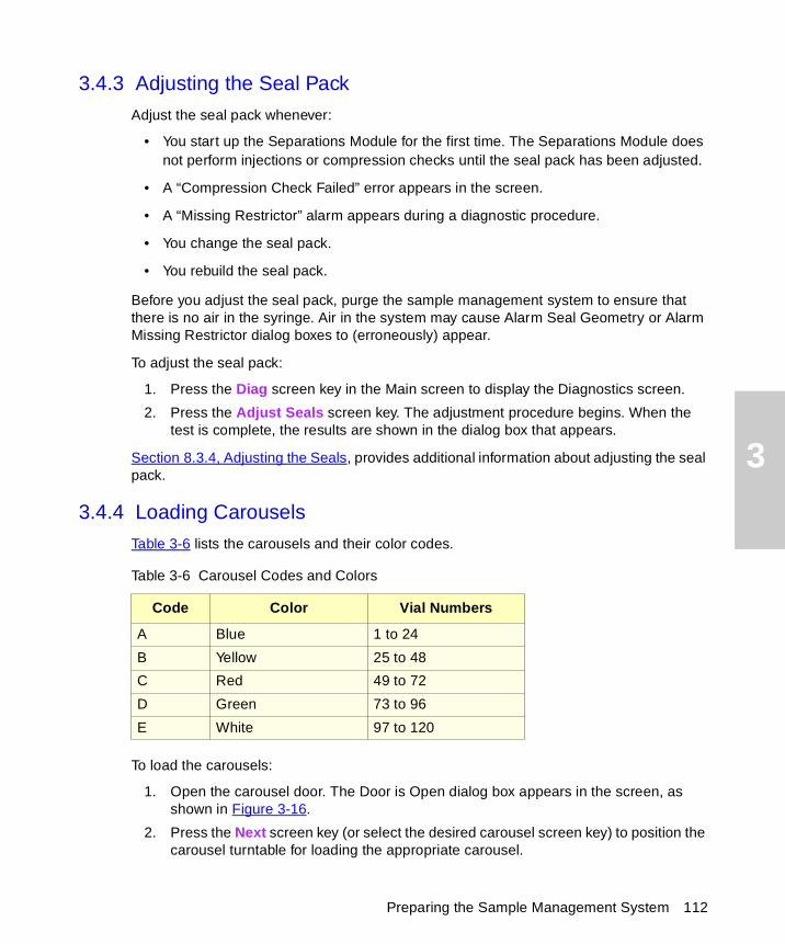
3
3.4.3 Adjusting the Seal Pack
Adjust the seal pack whenever:
• You start up the Separations Module for the first time. The Separations Module does not perform injections or compression checks until the seal pack has been adjusted.
• A “Compression Check Failed” error appears in the screen.
• A “Missing Restrictor” alarm appears during a diagnostic procedure.
• You change the seal pack.
• You rebuild the seal pack.
Before you adjust the seal pack, purge the sample management system to ensure that there is no air in the syringe. Air in the system may cause Alarm Seal Geometry or Alarm Missing Restrictor dialog boxes to (erroneously) appear.
To adjust the seal pack:
1. Press the Diag screen key in the Main screen to display the Diagnostics screen.
2. Press the Adjust Seals screen key. The adjustment procedure begins. When the test is complete, the results are shown in the dialog box that appears.
Section 8.3.4, Adjusting the Seals, provides additional information about adjusting the seal pack.
3.4.4 Loading Carousels
Table 3-6 lists the carousels and their color codes.
To load the carousels:
1. Open the carousel door. The Door is Open dialog box appears in the screen, as shown in Figure 3-16.
2. Press the Next screen key (or select the desired carousel screen key) to position the carousel turntable for loading the appropriate carousel.
Table 3-6 Carousel Codes and Colors
Code Color Vial Numbers
A Blue 1 to 24
B Yellow 25 to 48
C Red 49 to 72
D Green 73 to 96
E White 97 to 120
Preparing the Sample Management System 112
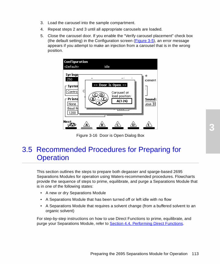
3
3. Load the carousel into the sample compartment.
4. Repeat steps 2 and 3 until all appropriate carousels are loaded.
5. Close the carousel door. If you enable the “Verify carousel placement” check box (the default setting) in the Configuration screen (Figure 3-5), an error message appears if you attempt to make an injection from a carousel that is in the wrong position.
Figure 3-16 Door is Open Dialog Box
3.5 Recommended Procedures for Preparing for Operation
This section outlines the steps to prepare both degasser and sparge-based 2695 Separations Modules for operation using Waters-recommended procedures. Flowcharts provide the sequence of steps to prime, equilibrate, and purge a Separations Module that is in one of the following states:
• A new or dry Separations Module
• A Separations Module that has been turned off or left idle with no flow
• A Separations Module that requires a solvent change (from a buffered solvent to an organic solvent)
For step-by-step instructions on how to use Direct Functions to prime, equilibrate, and purge your Separations Module, refer to Section 4.4, Performing Direct Functions.
Preparing the 2695 Separations Module for Operation 113

3
Figure 3-17 outlines how to prime, equilibrate, and purge a sparge-based Separations Module that is new or dry.
Figure 3-17 Preparing a New or Dry Separations Module for Operation(Sparge-Based Unit)
Fill the Solvent Reservoirs with Fresh Solvent Filtered and Degassed by
Vacuum Filtration (See Section 2.6.3)
Sparge all Reservoirs at an
Initial Sparge Rate of 100% for at Least 15 min., Then Set
an Idle Sparge Rate of 30 to 50%
(See Section 4.4.4)
Equilibrate for a Minimum of 10
Column Volumes (See Section 4.4.5)
Purge the Injector for a Minimum of 6
Loop Volumes (See “Purging the
Injector” in Section 4.4.2)
Perform a Dry Prime (to Fill Each
Solvent Line)See Section 4.4.1
Perform a Wet Prime (for One of the Solvents) for 5 min at 5.00 mL/min (See Section 4.4.2)
Repeat the Wet Prime (at the Same Rate and Time) for
Each Solvent
To Make a Gradient Run (for Example,
A:B), Set the A and B Composition Fields in the Status Screen to
50%, Then Wet Prime for 2 min at 5.00 mL/min
(See Section 4.4.2)
Start
Prime the Plunger Seal Wash Pump
(See Section 3.3.3)
Prime the Needle Wash Pump
(See Section 3.4.2)
Recommended Procedures for Preparing for Operation 114
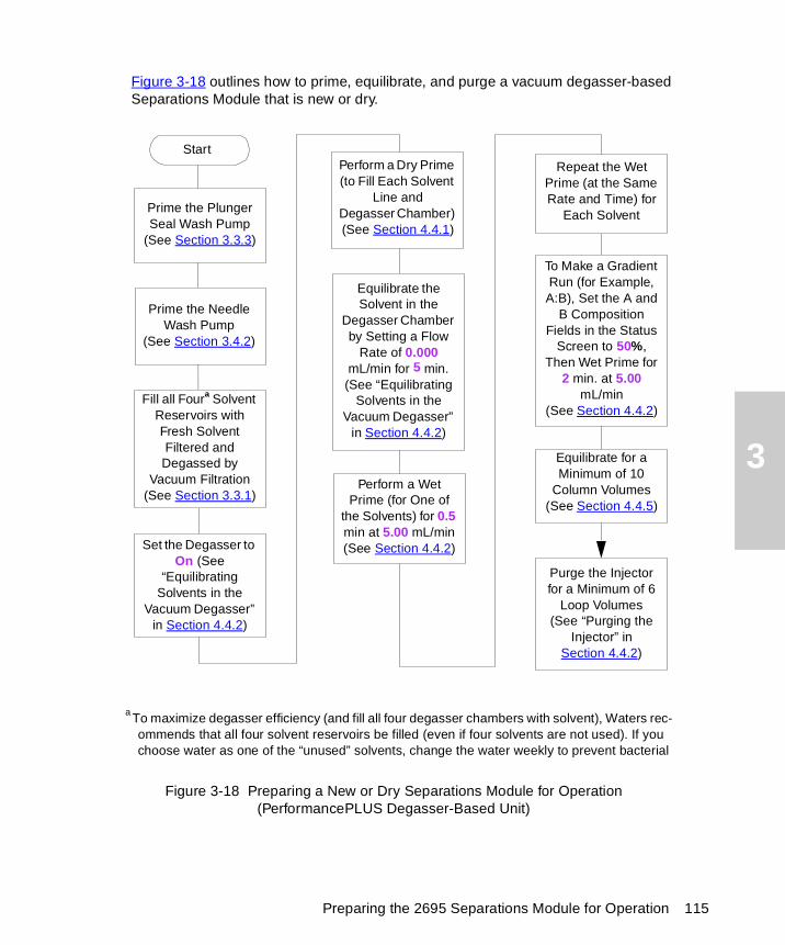
3
Figure 3-18 outlines how to prime, equilibrate, and purge a vacuum degasser-based Separations Module that is new or dry.
Figure 3-18 Preparing a New or Dry Separations Module for Operation(PerformancePLUS Degasser-Based Unit)
Fill all Foura Solvent Reservoirs with Fresh Solvent Filtered and Degassed by
Vacuum Filtration (See Section 3.3.1)
Set the Degasser to On (See
“Equilibrating Solvents in the
Vacuum Degasser” in Section 4.4.2)
Equilibrate for a Minimum of 10
Column Volumes (See Section 4.4.5)
Purge the Injector for a Minimum of 6
Loop Volumes (See “Purging the
Injector” in Section 4.4.2)
Perform a Dry Prime (to Fill Each Solvent
Line andDegasser Chamber) (See Section 4.4.1)
Perform a Wet Prime (for One of
the Solvents) for 0.5 min at 5.00 mL/min (See Section 4.4.2)
Repeat the Wet Prime (at the Same Rate and Time) for
Each Solvent
To Make a Gradient Run (for Example, A:B), Set the A and
B Composition Fields in the Status
Screen to 50%, Then Wet Prime for
2 min. at 5.00 mL/min
(See Section 4.4.2)
Start
Equilibrate the Solvent in the
Degasser Chamber by Setting a Flow
Rate of 0.000 mL/min for 5 min. (See “Equilibrating
Solvents in the Vacuum Degasser”
in Section 4.4.2)
a To maximize degasser efficiency (and fill all four degasser chambers with solvent), Waters rec-ommends that all four solvent reservoirs be filled (even if four solvents are not used). If you choose water as one of the “unused” solvents, change the water weekly to prevent bacterial
Prime the Plunger Seal Wash Pump
(See Section 3.3.3)
Prime the Needle Wash Pump
(See Section 3.4.2)
Preparing the 2695 Separations Module for Operation 115
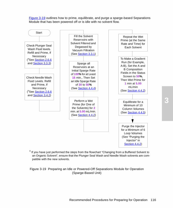
3
Figure 3-19 outlines how to prime, equilibrate, and purge a sparge-based Separations Module that has been powered off or is idle with no solvent flow.
Figure 3-19 Preparing an Idle or Powered-Off Separations Module for Operation(Sparge-Based Unit)
Fill the Solvent Reservoirs with
Solvent Filtered and Degassed by
Vacuum Filtration (See Section 3.3.1)
Sparge all Reservoirs at an
Initial Sparge Rate of 100% for at Least 15 min., Then Set
an Idle Sparge Rate of 30 to 50%
(See Section 4.4.4)
Equilibrate for a Minimum of 10
Column Volumes (See Section 4.4.5)
Purge the Injector for a Minimum of 6
Loop Volumes(See “Purging the
Injector” in Section 4.4.2)
Perform a Wet Prime (for One of the Solvents) for 2
min. at 5.00 mL/min. (See Section 4.4.2)
Repeat the Wet Prime (at the Same Rate and Time) for
Each Solvent
To Make a Gradient Run (for Example, A:B), Set the A and
B Composition Fields in the Status
Screen to 50%, Then Wet Prime for
1 min at 5.00 mL/min
(See Section 4.4.2)
Check Plunger Seal Wash Fluid levels. Refill and Prime, if
Necessary(aSee Section 2.6.6 and Section 3.3.3)
Check Needle Wash Fluid Levels. Refill
and Prime, if Necessary
(aSee Section 2.6.6 and Section 3.4.2)
a If you have just performed the steps from the flowchart “Changing from a Buffered Solvent to an Organic Solvent”, ensure that the Plunger Seal Wash and Needle Wash solvents are com-patible with the new solvents.
Start
Recommended Procedures for Preparing for Operation 116
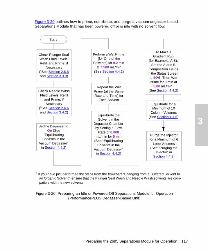
3
Figure 3-20 outlines how to prime, equilibrate, and purge a vacuum degasser-based Separations Module that has been powered off or is idle with no solvent flow.
Figure 3-20 Preparing an Idle or Powered-Off Separations Module for Operation(PerformancePLUS Degasser-Based Unit)
Set the Degasser to On (See
“Equilibrating Solvents in the
Vacuum Degasser” in Section 4.4.2)
Equilibrate for a Minimum of 10
Column Volumes (See Section 4.4.5)
Purge the Injector for a Minimum of 6
Loop Volumes (See “Purging the
Injector” in Section 4.4.2)
Perform a Wet Prime (for One of the
Solvents) for 0.2 min at 7.500 mL/min
(See Section 4.4.2)
Repeat the Wet Prime (at the Same Rate and Time) for
Each Solvent
To Make aGradient Run
(for Example, A:B), Set the A and B
Composition Fields in the Status Screen to 50%, Then Wet Prime for 3 min at
5.00 mL/min.(See Section 4.4.2)
Equilibrate the Solvent in the
Degasser Chamber by Setting a Flow
Rate of 0.000 mL/min for 5 min
(See “Equilibrating Solvents in the
Vacuum Degasser” in Section 4.4.2)
a If you have just performed the steps from the flowchart “Changing from a Buffered Solvent to an Organic Solvent”, ensure that the Plunger Seal Wash and Needle Wash solvents are com-patible with the new solvents.
Check Plunger Seal Wash Fluid Levels. Refill and Prime, if
Necessary(aSee Section 2.6.6 and Section 3.3.3)
Check Needle Wash Fluid Levels. Refill
and Prime, if Necessary
(aSee Section 2.6.6 and Section 3.4.2)
Start
Preparing the 2695 Separations Module for Operation 117
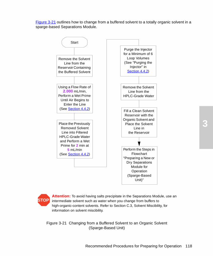
3
Figure 3-21 outlines how to change from a buffered solvent to a totally organic solvent in a sparge-based Separations Module.
Figure 3-21 Changing from a Buffered Solvent to an Organic Solvent(Sparge-Based Unit)
Remove the Solvent Line from the
Reservoir Containing the Buffered Solvent
Purge the Injector for a Minimum of 6
Loop Volumes (See “Purging the
Injector” in Section 4.4.2)
Using a Flow Rate of 2.000 mL/min,
Perform a Wet Prime Until Air Begins to
Enter the Line (See Section 4.4.2)
Fill a Clean Solvent Reservoir with the
Organic Solvent and Place the Solvent
Line inthe Reservoir
Place the Previously Removed Solvent Line into Filtered
HPLC-Grade Water and Perform a Wet Prime for 2 min at
5 mL/min (See Section 4.4.2)
Remove the Solvent Line from the
HPLC-Grade Water
STOPAttention: To avoid having salts precipitate in the Separations Module, use an intermediate solvent such as water when you change from buffers to high-organic-content solvents. Refer to Section C.3, Solvent Miscibility, for information on solvent miscibility.
Start
Perform the Steps in Flowchart
“Preparing a New or Dry Separations
Module for Operation
(Sparge-Based Unit)”
Recommended Procedures for Preparing for Operation 118
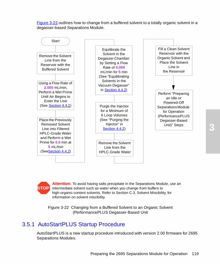
3
Figure 3-22 outlines how to change from a buffered solvent to a totally organic solvent in a degasser-based Separations Module.
Figure 3-22 Changing from a Buffered Solvent to an Organic Solvent(PerformancePLUS Degasser-Based Unit
3.5.1 AutoStartPLUS Startup Procedure
AutoStartPLUS is a new startup procedure introduced with version 2.00 firmware for 2695 Separations Modules.
Remove the Solvent Line from the
Reservoir with the Buffered Solvent
Purge the Injector for a Minimum of 6 Loop Volumes
(See “Purging the Injector” in
Section 4.4.2)
Using a Flow Rate of 2.000 mL/min,
Perform a Wet Prime Until Air Begins to
Enter the Line(See Section 4.4.2)
Fill a Clean Solvent Reservoir with the
Organic Solvent and Place the Solvent
Line inthe Reservoir
Place the Previously Removed Solvent Line into Filtered
HPLC-Grade Water and Perform a Wet Prime for 0.5 min at
5 mL/min (SeeSection 4.4.2)
Remove the Solvent Line from the
HPLC-Grade Water
Equilibrate the Solvent in the
Degasser Chamber by Setting a Flow
Rate of 0.000 mL/min for 5 min
(See “Equilibrating Solvents in the
Vacuum Degasser” in Section 4.4.2)
STOPAttention: To avoid having salts precipitate in the Separations Module, use an intermediate solvent such as water when you change from buffers to high-organic-content solvents. Refer to Section C.3, Solvent Miscibility, for information on solvent miscibility.
Perform “Preparing an Idle or
Powered-Off Separations Module
for Operation (PerformancePLUS
Degasser-Based Unit)” Steps
Start
Preparing the 2695 Separations Module for Operation 119
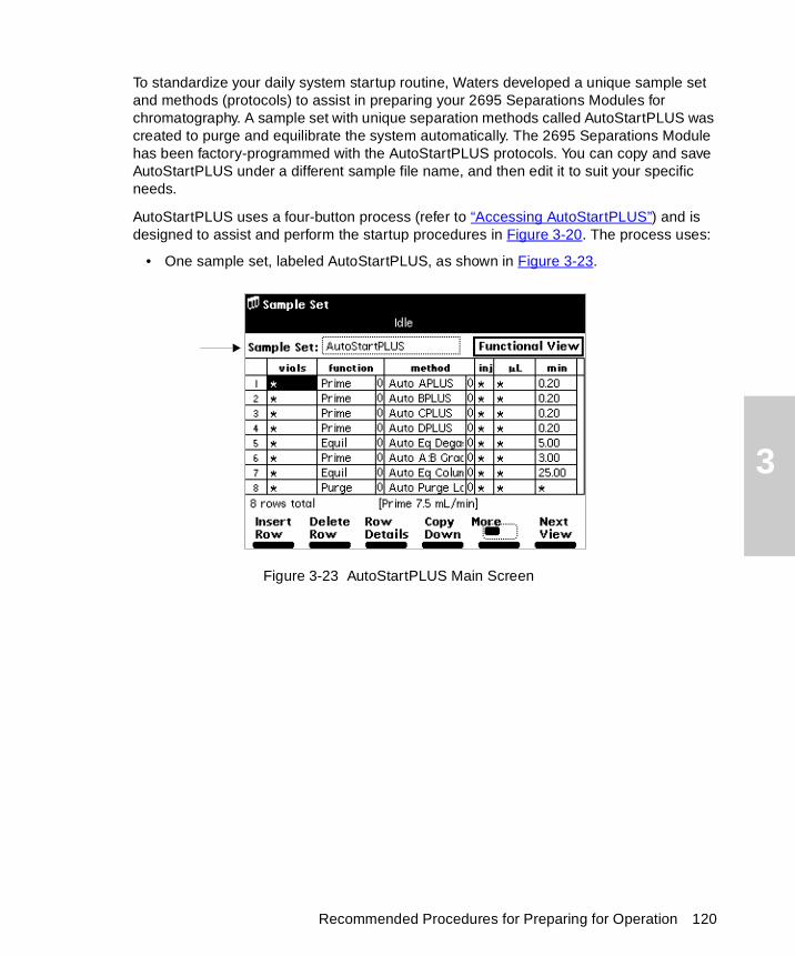
3
To standardize your daily system startup routine, Waters developed a unique sample set and methods (protocols) to assist in preparing your 2695 Separations Modules for chromatography. A sample set with unique separation methods called AutoStartPLUS was created to purge and equilibrate the system automatically. The 2695 Separations Module has been factory-programmed with the AutoStartPLUS protocols. You can copy and save AutoStartPLUS under a different sample file name, and then edit it to suit your specific needs.
AutoStartPLUS uses a four-button process (refer to “Accessing AutoStartPLUS”) and is designed to assist and perform the startup procedures in Figure 3-20. The process uses:
• One sample set, labeled AutoStartPLUS, as shown in Figure 3-23.
Figure 3-23 AutoStartPLUS Main Screen
Recommended Procedures for Preparing for Operation 120

3
• Eight AutoStartPLUS separation methods, as shown in Figure 3-24.
Figure 3-24 Methods Screen with AutoStartPLUS Selected
The run time for each method is listed Table 3-7. The methods are performed in the order listed in Table 3-7.
Table 3-7 AutoStartPLUS Run Times
Separation Method Run Time
Auto APLUS 20 seconds
Auto BPLUS 20 seconds
Auto CPLUS 20 seconds
Auto DPLUS 20 seconds
Auto Eq DegasPLUS 05 minutes
Auto A:B GradPLUS 03 minutes
Auto Eq ColumnPLUS 25 minutes
Auto Purge LoopPLUS 05 minutes
Total Run Time ~ 40 minutes
1234
5678
Preparing the 2695 Separations Module for Operation 121

3
Accessing AutoStartPLUS
To access and start AutoStartPLUS from the Waters 2695 Separations Module Main screen:
1. Press Run Samples to open the Methods screen.
2. Select the sample set labeled AutoStartPLUS.
3. Press Run.
4. Press Start.
5. Press Stat to begin the AutoStartPLUS run immediately or Routine to start the AutoStartPLUS run after the completion of the current work.
AutoStartPLUS Requirements
AutoStartPLUS was created assuming an A:B gradient and a 3.9 x 250 mm column are used (see Figure 3-20). If your conditions differ from these, see “Creating a Customized Start Method”.
• The 2695 Separations Module must:
– Display “Idle” status in the banner area of the Main screen. This means that all front-panel controls are accessible and fully functional.
– Have been left off or idle with no solvent flow for less than one week.
• Have the plunger-seal wash and needle-wash pumps primed and operational.
• Have the analytical solvents, plunger-seal wash, and needle-wash solutions present in sufficient quantities, or have been freshly prepared.
Note: Do not use aqueous-based solutions if it is possible that bacterial growth or contamination has occurred. Replace these with freshly prepared solutions.
• Use a binary gradient of Solvents A and B.
• Use a 3.9 x 250 mm column. Column equilibration is based on these column dimensions.
Setting Up the Separations Module for Operation
The AutoStartPLUS procedure follows the steps in Figure 3-20. It is intended for use with 2695 Separations Modules with the PerformancePLUS Inline Degasser.
Figure 3-25 shows the relationship of the AutoStartPLUS program to the step-by-step preparation of operation for the most commonly used startup routine (Figure 3-20). This flowchart reviews how to prime, equilibrate, and purge a PerformancePLUS vacuum degasser-based Separations Module that has been powered off or is idle with no solvent flow.
Recommended Procedures for Preparing for Operation 122
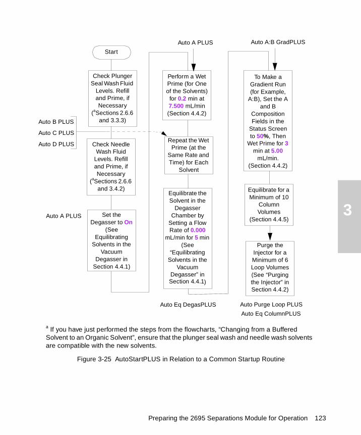
3
Figure 3-25 AutoStartPLUS in Relation to a Common Startup Routine
Set the Degasser to On
(See Equilibrating
Solvents in the Vacuum
Degasser in Section 4.4.1)
Equilibrate for a Minimum of 10
Column Volumes
(Section 4.4.5)
Purge the Injector for a Minimum of 6 Loop Volumes (See “Purging the Injector” in Section 4.4.2)
Perform a Wet Prime (for One of the Solvents)
for 0.2 min at 7.500 mL/min(Section 4.4.2)
Repeat the Wet Prime (at the
Same Rate and Time) for Each
Solvent
To Make aGradient Run(for Example,
A:B), Set the A and B
Composition Fields in the
Status Screen to 50%, Then
Wet Prime for 3 min at 5.00
mL/min.(Section 4.4.2)
Start
Equilibrate the Solvent in the
Degasser Chamber by
Setting a Flow Rate of 0.000
mL/min for 5 min (See
“Equilibrating Solvents in the
Vacuum Degasser” in Section 4.4.1)
a If you have just performed the steps from the flowcharts, “Changing from a Buffered Solvent to an Organic Solvent”, ensure that the plunger seal wash and needle wash solvents are compatible with the new solvents.
Check Plunger Seal Wash Fluid
Levels. Refill and Prime, if Necessary
(aSections 2.6.6 and 3.3.3)
Check Needle Wash Fluid
Levels. Refill and Prime, if Necessary
(aSections 2.6.6 and 3.4.2)
Auto A PLUS
Auto Eq DegasPLUS
Auto B PLUS
Auto C PLUS
Auto D PLUS
Auto A:B GradPLUS
Auto Eq ColumnPLUS
Auto Purge Loop PLUS
Auto A PLUS
Preparing the 2695 Separations Module for Operation 123
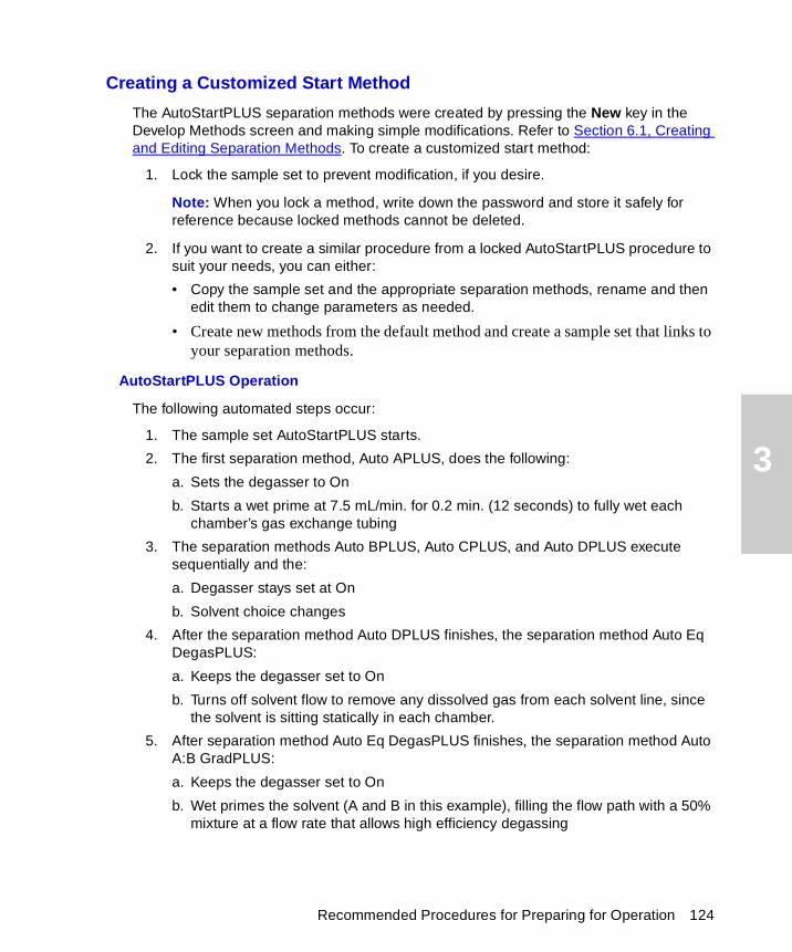
3
Creating a Customized Start Method
The AutoStartPLUS separation methods were created by pressing the New key in the Develop Methods screen and making simple modifications. Refer to Section 6.1, Creating and Editing Separation Methods. To create a customized start method:
1. Lock the sample set to prevent modification, if you desire.
Note: When you lock a method, write down the password and store it safely for reference because locked methods cannot be deleted.
2. If you want to create a similar procedure from a locked AutoStartPLUS procedure to suit your needs, you can either:
• Copy the sample set and the appropriate separation methods, rename and then edit them to change parameters as needed.
• Create new methods from the default method and create a sample set that links to your separation methods.
AutoStartPLUS Operation
The following automated steps occur:
1. The sample set AutoStartPLUS starts.
2. The first separation method, Auto APLUS, does the following:
a. Sets the degasser to On
b. Starts a wet prime at 7.5 mL/min. for 0.2 min. (12 seconds) to fully wet each chamber’s gas exchange tubing
3. The separation methods Auto BPLUS, Auto CPLUS, and Auto DPLUS execute sequentially and the:
a. Degasser stays set at On
b. Solvent choice changes
4. After the separation method Auto DPLUS finishes, the separation method Auto Eq DegasPLUS:
a. Keeps the degasser set to On
b. Turns off solvent flow to remove any dissolved gas from each solvent line, since the solvent is sitting statically in each chamber.
5. After separation method Auto Eq DegasPLUS finishes, the separation method Auto A:B GradPLUS:
a. Keeps the degasser set to On
b. Wet primes the solvent (A and B in this example), filling the flow path with a 50% mixture at a flow rate that allows high efficiency degassing
Recommended Procedures for Preparing for Operation 124
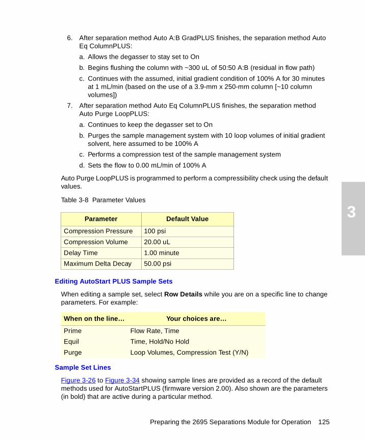
3
6. After separation method Auto A:B GradPLUS finishes, the separation method Auto Eq ColumnPLUS:
a. Allows the degasser to stay set to On
b. Begins flushing the column with ~300 uL of 50:50 A:B (residual in flow path)
c. Continues with the assumed, initial gradient condition of 100% A for 30 minutes at 1 mL/min (based on the use of a 3.9-mm x 250-mm column [~10 column volumes])
7. After separation method Auto Eq ColumnPLUS finishes, the separation method Auto Purge LoopPLUS:
a. Continues to keep the degasser set to On
b. Purges the sample management system with 10 loop volumes of initial gradient solvent, here assumed to be 100% A
c. Performs a compression test of the sample management system
d. Sets the flow to 0.00 mL/min of 100% A
Auto Purge LoopPLUS is programmed to perform a compressibility check using the default values.
Table 3-8 Parameter Values
Editing AutoStart PLUS Sample Sets
When editing a sample set, select Row Details while you are on a specific line to change parameters. For example:
Sample Set Lines
Figure 3-26 to Figure 3-34 showing sample lines are provided as a record of the default methods used for AutoStartPLUS (firmware version 2.00). Also shown are the parameters (in bold) that are active during a particular method.
Parameter Default Value
Compression Pressure 100 psi
Compression Volume 20.00 uL
Delay Time 1.00 minute
Maximum Delta Decay 50.00 psi
When on the line… Your choices are…
Prime Flow Rate, Time
Equil Time, Hold/No Hold
Purge Loop Volumes, Compression Test (Y/N)
Preparing the 2695 Separations Module for Operation 125
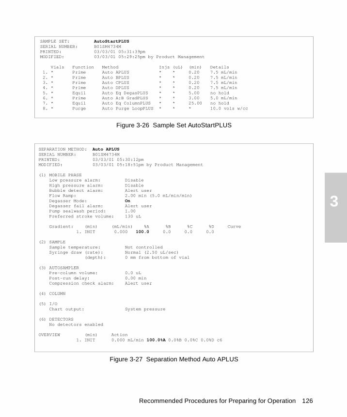
3
Figure 3-26 Sample Set AutoStartPLUS
Figure 3-27 Separation Method Auto APLUS
SAMPLE SET: AutoStartPLUSSERIAL NUMBER: B01SM4734MPRINTED: 03/03/01 05:31:39pmMODIFIED: 03/03/01 05:29:25pm by Product Management
Vials Function Method Injs (uL) (min) Details 1. * Prime Auto APLUS * * 0.20 7.5 mL/min 2. * Prime Auto BPLUS * * 0.20 7.5 mL/min 3. * Prime Auto CPLUS * * 0.20 7.5 mL/min 4. * Prime Auto DPLUS * * 0.20 7.5 mL/min 5. * Equil Auto Eq DegasPLUS * * 5.00 no hold 6. * Prime Auto A:B GradPLUS * * 3.00 5.0 mL/min 7. * Equil Auto Eq ColumnPLUS * * 25.00 no hold 8. * Purge Auto Purge LoopPLUS * * * 10.0 vols w/cc
SEPARATION METHOD: Auto APLUSSERIAL NUMBER: B01SM4734MPRINTED: 03/03/01 05:30:12pmMODIFIED: 03/03/01 05:18:51pm by Product Management
(1) MOBILE PHASE Low pressure alarm: Disable High pressure alarm: Disable Bubble detect alarm: Alert user Flow Ramp: 2.00 min (5.0 mL/min/min) Degasser Mode: On Degasser fail alarm: Alert user Pump sealwash period: 1.00 Preferred stroke volume: 130 uL Gradient: (min) (mL/min) %A %B %C %D Curve 1. INIT 0.000 100.0 0.0 0.0 0.0 (2) SAMPLE Sample temperature: Not controlled Syringe draw (rate): Normal (2.50 uL/sec) (depth): 0 mm from bottom of vial (3) AUTOSAMPLER Pre-column volume: 0.0 uL Post-run delay: 0.00 min Compression check alarm: Alert user (4) COLUMN (5) I/O Chart output: System pressure (6) DETECTORS No detectors enabled OVERVIEW (min) Action 1. INIT 0.000 mL/min 100.0%A 0.0%B 0.0%C 0.0%D c6
Recommended Procedures for Preparing for Operation 126
3
Figure 3-28 Separation Method Auto BPLUS
SEPARATION METHOD: Auto BPLUSSERIAL NUMBER: B01SM4734MPRINTED: 03/03/01 05:30:36pmMODIFIED: 03/03/01 05:19:12pm by Product Management
(1) MOBILE PHASE Low pressure alarm: Disable High pressure alarm: Disable Bubble detect alarm: Alert user Flow Ramp: 2.00 min (5.0 mL/min/min) Degasser Mode: On Degasser fail alarm: Alert user Pump sealwash period: 1.00 Preferred stroke volume: 130 uL Gradient: (min) (mL/min) %A %B %C %D Curve 1. INIT 0.000 0.0 100.0 0.0 0.0 (2) SAMPLE Sample temperature: Not controlled Syringe draw (rate): Normal (2.50 uL/sec) (depth): 0 mm from bottom of vial (3) AUTOSAMPLER Pre-column volume: 0.0 uL Post-run delay: 0.00 min Compression check alarm: Alert user (4) COLUMN (5) I/O Chart output: System pressure (6) DETECTORS No detectors enabled
OVERVIEW (min) Action 1. INIT 0.000 mL/min 0.0%A 100.0%B 0.0%C 0.0%D c6
Preparing the 2695 Separations Module for Operation 127
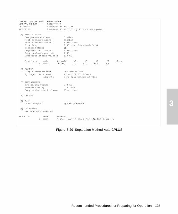
3
Figure 3-29 Separation Method Auto CPLUS
SEPARATION METHOD: Auto CPLUSSERIAL NUMBER: B01SM4734MPRINTED: 03/03/01 05:30:23pmMODIFIED: 03/03/01 05:19:32pm by Product Management
(1) MOBILE PHASE Low pressure alarm: Disable High pressure alarm: Disable Bubble detect alarm: Alert user Flow Ramp: 2.00 min (5.0 mL/min/min) Degasser Mode: On Degasser fail alarm: Alert user Pump sealwash period: 1.00 Preferred stroke volume: 130 uL Gradient: (min) (mL/min) %A %B %C %D Curve 1. INIT 0.000 0.0 0.0 100.0 0.0 (2) SAMPLE Sample temperature: Not controlled Syringe draw (rate): Normal (2.50 uL/sec) (depth): 0 mm from bottom of vial (3) AUTOSAMPLER Pre-column volume: 0.0 uL Post-run delay: 0.00 min Compression check alarm: Alert user (4) COLUMN (5) I/O Chart output: System pressure (6) DETECTORS No detectors enabled OVERVIEW (min) Action 1. INIT 0.000 mL/min 0.0%A 0.0%B 100.0%C 0.0%D c6
Recommended Procedures for Preparing for Operation 128
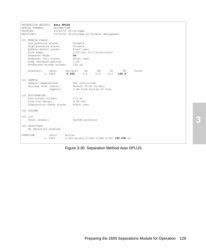
3
Figure 3-30 Separation Method Auto DPLUS
SEPARATION METHOD: Auto DPLUSSERIAL NUMBER: B01SM4734MPRINTED: 03/03/01 05:30:46pmMODIFIED: 03/03/01 05:20:03pm by Product Management
(1) MOBILE PHASE Low pressure alarm: Disable High pressure alarm: Disable Bubble detect alarm: Alert user Flow Ramp: 2.00 min (5.0 mL/min/min) Degasser Mode: On Degasser fail alarm: Alert user Pump sealwash period: 1.00 Preferred stroke volume: 130 uL Gradient: (min) (mL/min) %A %B %C %D Curve 1. INIT 0.000 0.0 0.0 0.0 100.0 (2) SAMPLE Sample temperature: Not controlled Syringe draw (rate): Normal (2.50 uL/sec) (depth): 0 mm from bottom of vial (3) AUTOSAMPLER Pre-column volume: 0.0 uL Post-run delay: 0.00 min Compression check alarm: Alert user (4) COLUMN (5) I/O Chart output: System pressure (6) DETECTORS No detectors enabled OVERVIEW (min) Action 1. INIT 0.000 mL/min 0.0%A 0.0%B 0.0%C 100.0%D c6
Preparing the 2695 Separations Module for Operation 129

3
Figure 3-31 Separation Method Auto Eq DegasPLUS
SEPARATION METHOD: Auto Eq DegasPLUSSERIAL NUMBER: B01SM4734MPRINTED: 03/03/01 05:31:14pmMODIFIED: 03/03/01 05:20:21pm by Product Management
(1) MOBILE PHASE Low pressure alarm: Disable High pressure alarm: Disable Bubble detect alarm: Alert user Flow Ramp: 2.00 min (5.0 mL/min/min) Degasser Mode: On Degasser fail alarm: Alert user Pump sealwash period: 1.00 Preferred stroke volume: 130 uL Gradient: (min) (mL/min) %A %B %C %D Curve 1. INIT 0.000 100.0 0.0 0.0 0.0 (2) SAMPLE Sample temperature: Not controlled Syringe draw (rate): Normal (2.50 uL/sec) (depth): 0 mm from bottom of vial (3) AUTOSAMPLER Pre-column volume: 0.0 uL Post-run delay: 0.00 min Compression check alarm: Alert user (4) COLUMN (5) I/O Chart output: System pressure (6) DETECTORS No detectors enabled OVERVIEW (min) Action 1. INIT 0.000 mL/min 100.0%A 0.0%B 0.0%C 0.0%D c6
Recommended Procedures for Preparing for Operation 130
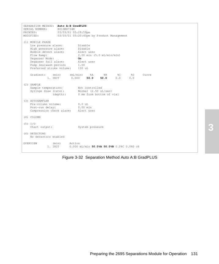
3
Figure 3-32 Separation Method Auto A:B GradPLUS
SEPARATION METHOD: Auto A:B GradPLUSSERIAL NUMBER: B01SM4734MPRINTED: 03/03/01 05:29:59pmMODIFIED: 03/03/01 05:20:40pm by Product Management
(1) MOBILE PHASE Low pressure alarm: Disable High pressure alarm: Disable Bubble detect alarm: Alert user Flow Ramp: 2.00 min (5.0 mL/min/min) Degasser Mode: On Degasser fail alarm: Alert user Pump sealwash period: 1.00 Preferred stroke volume: 130 uL Gradient: (min) (mL/min) %A %B %C %D Curve 1. INIT 0.000 50.0 50.0 0.0 0.0 (2) SAMPLE Sample temperature: Not controlled Syringe draw (rate): Normal (2.50 uL/sec) (depth): 0 mm from bottom of vial (3) AUTOSAMPLER Pre-column volume: 0.0 uL Post-run delay: 0.00 min Compression check alarm: Alert user (4) COLUMN (5) I/O Chart output: System pressure (6) DETECTORS No detectors enabled OVERVIEW (min) Action 1. INIT 0.000 mL/min 50.0%A 50.0%B 0.0%C 0.0%D c6
Preparing the 2695 Separations Module for Operation 131
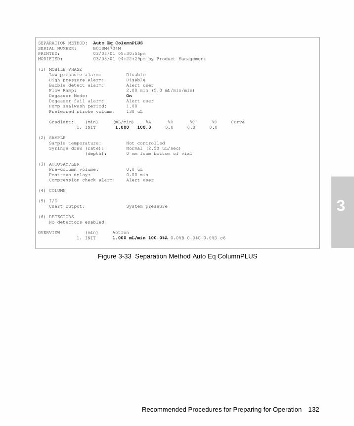
3
Figure 3-33 Separation Method Auto Eq ColumnPLUS
SEPARATION METHOD: Auto Eq ColumnPLUSSERIAL NUMBER: B01SM4734MPRINTED: 03/03/01 05:30:55pmMODIFIED: 03/03/01 04:22:29pm by Product Management
(1) MOBILE PHASE Low pressure alarm: Disable High pressure alarm: Disable Bubble detect alarm: Alert user Flow Ramp: 2.00 min (5.0 mL/min/min) Degasser Mode: On Degasser fail alarm: Alert user Pump sealwash period: 1.00 Preferred stroke volume: 130 uL Gradient: (min) (mL/min) %A %B %C %D Curve 1. INIT 1.000 100.0 0.0 0.0 0.0 (2) SAMPLE Sample temperature: Not controlled Syringe draw (rate): Normal (2.50 uL/sec) (depth): 0 mm from bottom of vial (3) AUTOSAMPLER Pre-column volume: 0.0 uL Post-run delay: 0.00 min Compression check alarm: Alert user (4) COLUMN (5) I/O Chart output: System pressure (6) DETECTORS No detectors enabled OVERVIEW (min) Action 1. INIT 1.000 mL/min 100.0%A 0.0%B 0.0%C 0.0%D c6
Recommended Procedures for Preparing for Operation 132
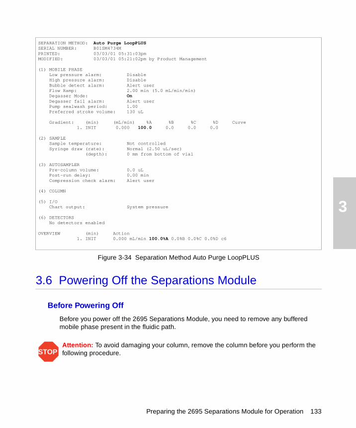
3
Figure 3-34 Separation Method Auto Purge LoopPLUS
3.6 Powering Off the Separations Module
Before Powering Off
Before you power off the 2695 Separations Module, you need to remove any buffered mobile phase present in the fluidic path.
STOPAttention: To avoid damaging your column, remove the column before you perform the following procedure.
SEPARATION METHOD: Auto Purge LoopPLUSSERIAL NUMBER: B01SM4734MPRINTED: 03/03/01 05:31:03pmMODIFIED: 03/03/01 05:21:02pm by Product Management
(1) MOBILE PHASE Low pressure alarm: Disable High pressure alarm: Disable Bubble detect alarm: Alert user Flow Ramp: 2.00 min (5.0 mL/min/min) Degasser Mode: On Degasser fail alarm: Alert user Pump sealwash period: 1.00 Preferred stroke volume: 130 uL Gradient: (min) (mL/min) %A %B %C %D Curve 1. INIT 0.000 100.0 0.0 0.0 0.0 (2) SAMPLE Sample temperature: Not controlled Syringe draw (rate): Normal (2.50 uL/sec) (depth): 0 mm from bottom of vial (3) AUTOSAMPLER Pre-column volume: 0.0 uL Post-run delay: 0.00 min Compression check alarm: Alert user (4) COLUMN (5) I/O Chart output: System pressure (6) DETECTORS No detectors enabled OVERVIEW (min) Action 1. INIT 0.000 mL/min 100.0%A 0.0%B 0.0%C 0.0%D c6
Preparing the 2695 Separations Module for Operation 133
3
To remove buffered mobile phase from the fluidic path of the Separations Module:
1. Replace the buffered mobile phase with HPLC-quality water and wet prime the system for 10 minutes at 3 mL/min (see Section 4.4.2, Performing a Wet Prime).
2. Perform three injector purge cycles to ensure that the sample loop is clean (see Section 4.4.2, “Purging the Injector” discussion.
3. Replace the plunger seal-wash solvent with a fresh solution of 80% water:20% methanol or a miscible solvent, and prime the plunger seal-wash pump (see Section 3.3.3, Priming the Plunger Seal-Wash Pump).
4. Replace the water mobile phase with a solution of 90% methanol:10% water, and flush the system for 10 minutes at 3 mL/min.
5. Replace the needle-wash solvent with a solution of 90% methanol:10% water or a miscible solvent, and perform a needle-wash prime (see Section 3.4.2, Priming the Needle-Wash Pump).
Powering Off
To power off the Separations Module:
1. Ensure that the system has been flushed properly (see the “Before Powering Off” discussion above).
2. Press the power switch to the (Off) 0 position. The time and date of power-off are entered in the log file.
Powering Off the Separations Module 134
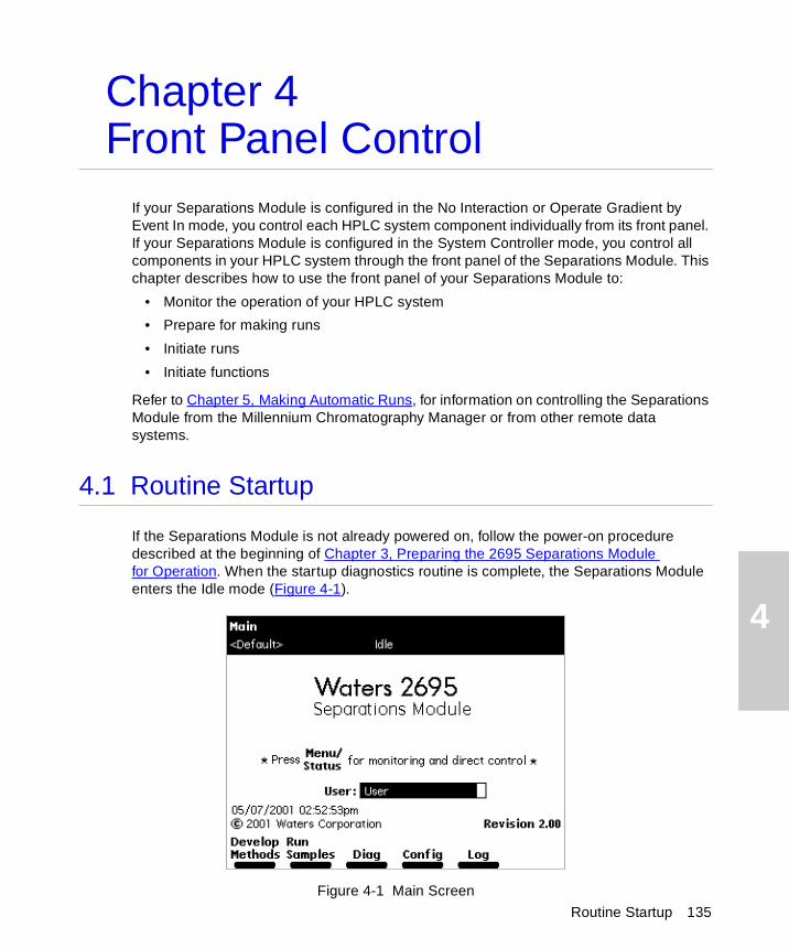
4
Routine Startup 135
Chapter 4Front Panel Control
If your Separations Module is configured in the No Interaction or Operate Gradient by Event In mode, you control each HPLC system component individually from its front panel. If your Separations Module is configured in the System Controller mode, you control all components in your HPLC system through the front panel of the Separations Module. This chapter describes how to use the front panel of your Separations Module to:
• Monitor the operation of your HPLC system
• Prepare for making runs
• Initiate runs
• Initiate functions
Refer to Chapter 5, Making Automatic Runs, for information on controlling the Separations Module from the Millennium Chromatography Manager or from other remote data systems.
4.1 Routine Startup
If the Separations Module is not already powered on, follow the power-on procedure described at the beginning of Chapter 3, Preparing the 2695 Separations Module for Operation. When the startup diagnostics routine is complete, the Separations Module enters the Idle mode (Figure 4-1).
Figure 4-1 Main Screen
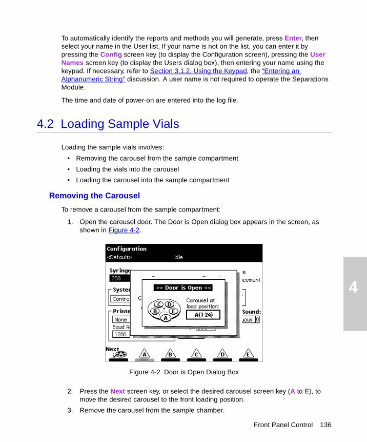
4
To automatically identify the reports and methods you will generate, press Enter, then select your name in the User list. If your name is not on the list, you can enter it by pressing the Config screen key (to display the Configuration screen), pressing the User Names screen key (to display the Users dialog box), then entering your name using the keypad. If necessary, refer to Section 3.1.2, Using the Keypad, the “Entering an Alphanumeric String” discussion. A user name is not required to operate the Separations Module.
The time and date of power-on are entered into the log file.
4.2 Loading Sample Vials
Loading the sample vials involves:
• Removing the carousel from the sample compartment
• Loading the vials into the carousel
• Loading the carousel into the sample compartment
Removing the Carousel
To remove a carousel from the sample compartment:
1. Open the carousel door. The Door is Open dialog box appears in the screen, as shown in Figure 4-2.
Figure 4-2 Door is Open Dialog Box
2. Press the Next screen key, or select the desired carousel screen key (A to E), to move the desired carousel to the front loading position.
3. Remove the carousel from the sample chamber.
Front Panel Control 136
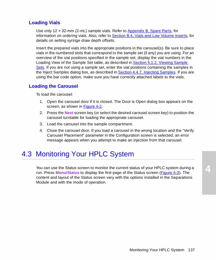
4
Loading Vials
Use only 12 × 32-mm (2-mL) sample vials. Refer to Appendix B, Spare Parts, for information on ordering vials. Also, refer to Section B.4, Vials and Low Volume Inserts, for details on setting syringe draw depth offsets.
Insert the prepared vials into the appropriate positions in the carousel(s). Be sure to place vials in the numbered slots that correspond to the sample set (if any) you are using. For an overview of the vial positions specified in the sample set, display the vial numbers in the Loading View of the Sample Set table, as described in Section 5.1.2, Viewing Sample Sets. If you are not using a sample set, enter the vial positions containing the samples in the Inject Samples dialog box, as described in Section 4.4.7, Injecting Samples. If you are using the bar code option, make sure you have correctly attached labels to the vials.
Loading the Carousel
To load the carousel:
1. Open the carousel door if it is closed. The Door is Open dialog box appears on the screen, as shown in Figure 4-2.
2. Press the Next screen key (or select the desired carousel screen key) to position the carousel turntable for loading the appropriate carousel.
3. Load the carousel into the sample compartment.
4. Close the carousel door. If you load a carousel in the wrong location and the “Verify Carousel Placement” parameter in the Configuration screen is selected, an error message appears when you attempt to make an injection from that carousel.
4.3 Monitoring Your HPLC System
You can use the Status screen to monitor the current status of your HPLC system during a run. Press Menu/Status to display the first page of the Status screen (Figure 4-3). The content and layout of the Status screen vary with the options installed in the Separations Module and with the mode of operation.
Monitoring Your HPLC System 137
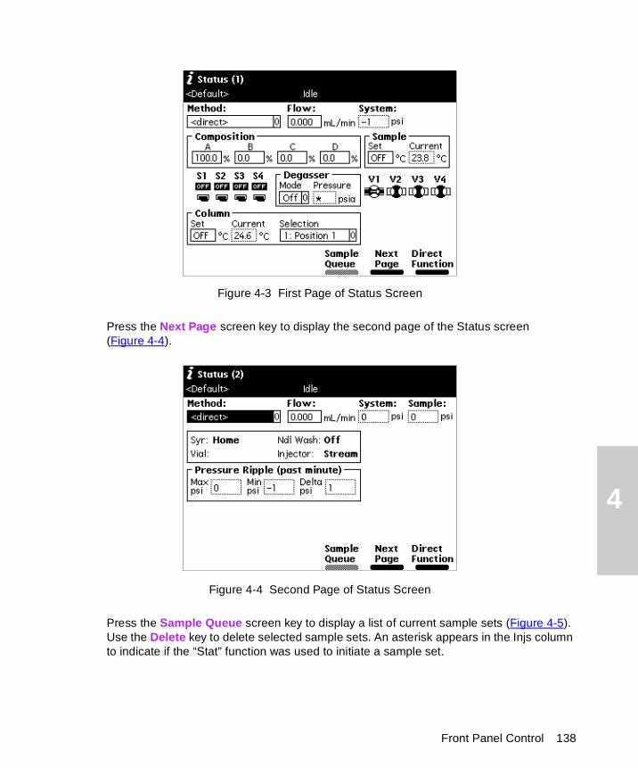
4
Figure 4-3 First Page of Status Screen
Press the Next Page screen key to display the second page of the Status screen (Figure 4-4).
Figure 4-4 Second Page of Status Screen
Press the Sample Queue screen key to display a list of current sample sets (Figure 4-5). Use the Delete key to delete selected sample sets. An asterisk appears in the Injs column to indicate if the “Stat” function was used to initiate a sample set.
Front Panel Control 138
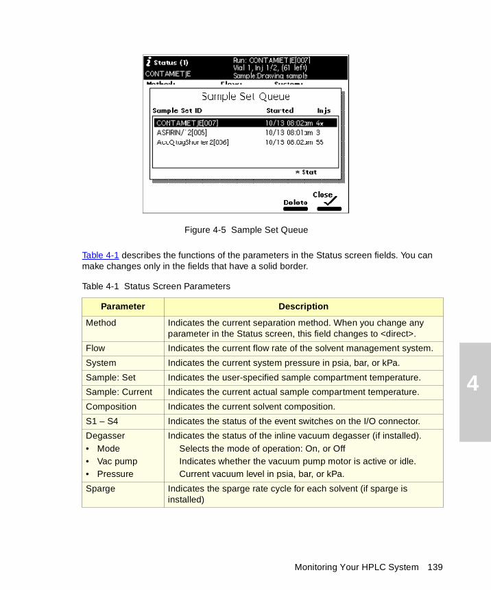
4
Figure 4-5 Sample Set Queue
Table 4-1 describes the functions of the parameters in the Status screen fields. You can make changes only in the fields that have a solid border.
Table 4-1 Status Screen Parameters
Parameter Description
Method Indicates the current separation method. When you change any parameter in the Status screen, this field changes to <direct>.
Flow Indicates the current flow rate of the solvent management system.
System Indicates the current system pressure in psia, bar, or kPa.
Sample: Set Indicates the user-specified sample compartment temperature.
Sample: Current Indicates the current actual sample compartment temperature.
Composition Indicates the current solvent composition.
S1 – S4 Indicates the status of the event switches on the I/O connector.
Degasser• Mode• Vac pump• Pressure
Indicates the status of the inline vacuum degasser (if installed).Selects the mode of operation: On, or OffIndicates whether the vacuum pump motor is active or idle.Current vacuum level in psia, bar, or kPa.
Sparge Indicates the sparge rate cycle for each solvent (if sparge is installed)
Monitoring Your HPLC System 139
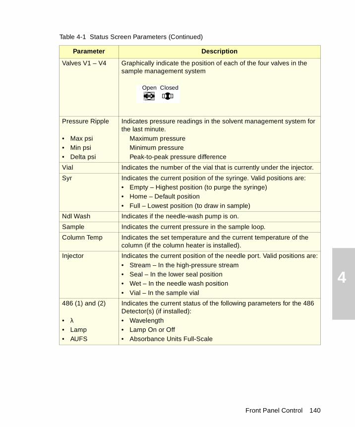
4
Valves V1 – V4 Graphically indicate the position of each of the four valves in the sample management system
Pressure Ripple
• Max psi• Min psi• Delta psi
Indicates pressure readings in the solvent management system for the last minute.
Maximum pressureMinimum pressurePeak-to-peak pressure difference
Vial Indicates the number of the vial that is currently under the injector.
Syr Indicates the current position of the syringe. Valid positions are:• Empty – Highest position (to purge the syringe)• Home – Default position• Full – Lowest position (to draw in sample)
Ndl Wash Indicates if the needle-wash pump is on.
Sample Indicates the current pressure in the sample loop.
Column Temp Indicates the set temperature and the current temperature of the column (if the column heater is installed).
Injector Indicates the current position of the needle port. Valid positions are:• Stream – In the high-pressure stream• Seal – In the lower seal position• Wet – In the needle wash position• Vial – In the sample vial
486 (1) and (2)
• λ• Lamp• AUFS
Indicates the current status of the following parameters for the 486 Detector(s) (if installed):• Wavelength• Lamp On or Off• Absorbance Units Full-Scale
Table 4-1 Status Screen Parameters (Continued)
Parameter Description
Open Closed
Front Panel Control 140
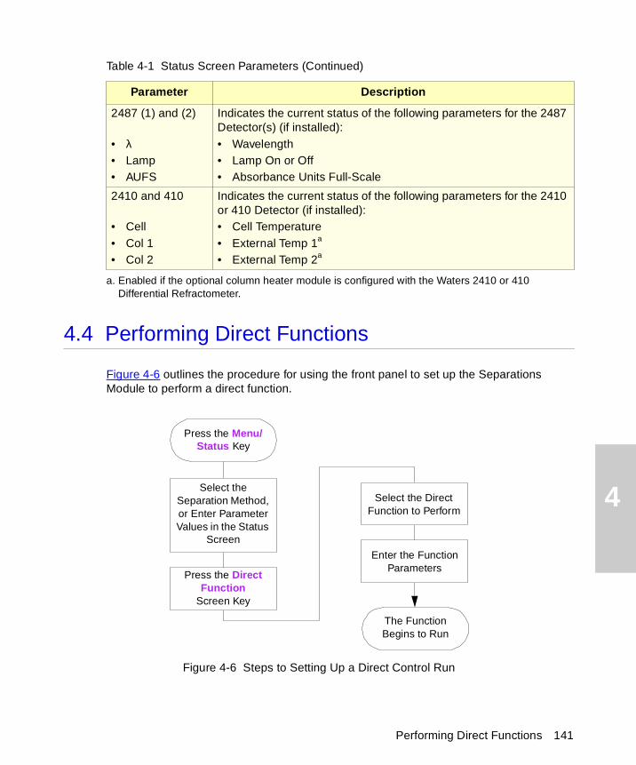
4
4.4 Performing Direct Functions
Figure 4-6 outlines the procedure for using the front panel to set up the Separations Module to perform a direct function.
Figure 4-6 Steps to Setting Up a Direct Control Run
2487 (1) and (2)
• λ• Lamp• AUFS
Indicates the current status of the following parameters for the 2487 Detector(s) (if installed):• Wavelength• Lamp On or Off• Absorbance Units Full-Scale
2410 and 410
• Cell• Col 1• Col 2
Indicates the current status of the following parameters for the 2410 or 410 Detector (if installed):• Cell Temperature• External Temp 1a
• External Temp 2a
a. Enabled if the optional column heater module is configured with the Waters 2410 or 410 Differential Refractometer.
Table 4-1 Status Screen Parameters (Continued)
Parameter Description
Press the Menu/ Status Key
The Function Begins to Run
Select the Separation Method, or Enter Parameter Values in the Status
Screen
Press the Direct Function
Screen Key
Select the Direct Function to Perform
Enter the Function Parameters
Performing Direct Functions 141
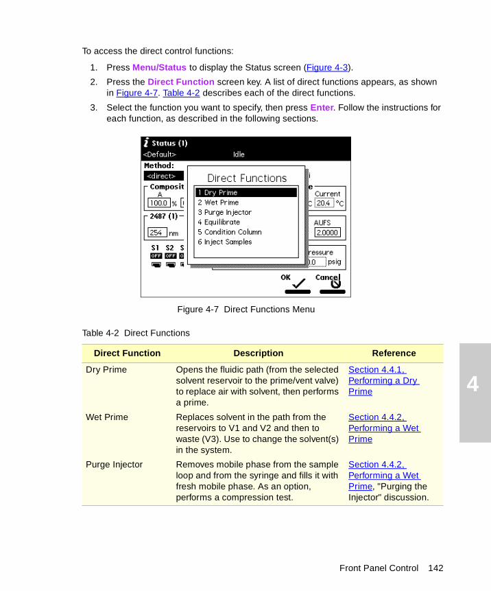
4
To access the direct control functions:
1. Press Menu/Status to display the Status screen (Figure 4-3).
2. Press the Direct Function screen key. A list of direct functions appears, as shown in Figure 4-7. Table 4-2 describes each of the direct functions.
3. Select the function you want to specify, then press Enter. Follow the instructions for each function, as described in the following sections.
Figure 4-7 Direct Functions Menu
Table 4-2 Direct Functions
Direct Function Description Reference
Dry Prime Opens the fluidic path (from the selected solvent reservoir to the prime/vent valve) to replace air with solvent, then performs a prime.
Section 4.4.1, Performing a Dry Prime
Wet Prime Replaces solvent in the path from the reservoirs to V1 and V2 and then to waste (V3). Use to change the solvent(s) in the system.
Section 4.4.2, Performing a Wet Prime
Purge Injector Removes mobile phase from the sample loop and from the syringe and fills it with fresh mobile phase. As an option, performs a compression test.
Section 4.4.2, Performing a Wet Prime, "Purging the Injector" discussion.
Front Panel Control 142
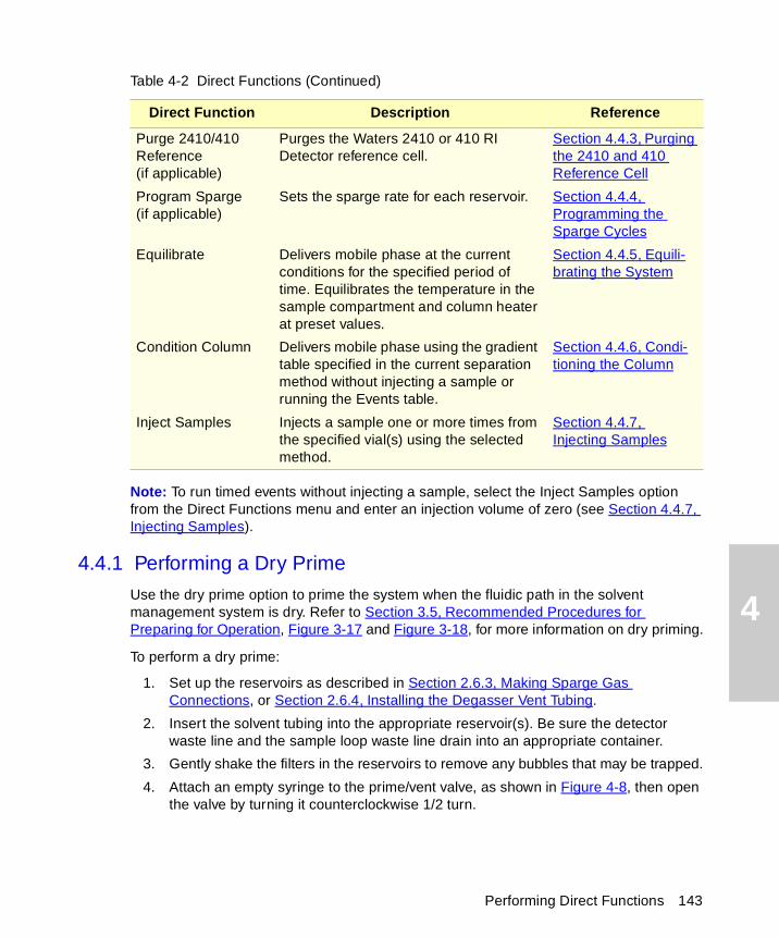
4
Note: To run timed events without injecting a sample, select the Inject Samples option from the Direct Functions menu and enter an injection volume of zero (see Section 4.4.7, Injecting Samples).
4.4.1 Performing a Dry Prime
Use the dry prime option to prime the system when the fluidic path in the solvent management system is dry. Refer to Section 3.5, Recommended Procedures for Preparing for Operation, Figure 3-17 and Figure 3-18, for more information on dry priming.
To perform a dry prime:
1. Set up the reservoirs as described in Section 2.6.3, Making Sparge Gas Connections, or Section 2.6.4, Installing the Degasser Vent Tubing.
2. Insert the solvent tubing into the appropriate reservoir(s). Be sure the detector waste line and the sample loop waste line drain into an appropriate container.
3. Gently shake the filters in the reservoirs to remove any bubbles that may be trapped.
4. Attach an empty syringe to the prime/vent valve, as shown in Figure 4-8, then open the valve by turning it counterclockwise 1/2 turn.
Purge 2410/410 Reference(if applicable)
Purges the Waters 2410 or 410 RI Detector reference cell.
Section 4.4.3, Purging the 2410 and 410 Reference Cell
Program Sparge (if applicable)
Sets the sparge rate for each reservoir. Section 4.4.4, Programming the Sparge Cycles
Equilibrate Delivers mobile phase at the current conditions for the specified period of time. Equilibrates the temperature in the sample compartment and column heater at preset values.
Section 4.4.5, Equili-brating the System
Condition Column Delivers mobile phase using the gradient table specified in the current separation method without injecting a sample or running the Events table.
Section 4.4.6, Condi-tioning the Column
Inject Samples Injects a sample one or more times from the specified vial(s) using the selected method.
Section 4.4.7, Injecting Samples
Table 4-2 Direct Functions (Continued)
Direct Function Description Reference
Performing Direct Functions 143
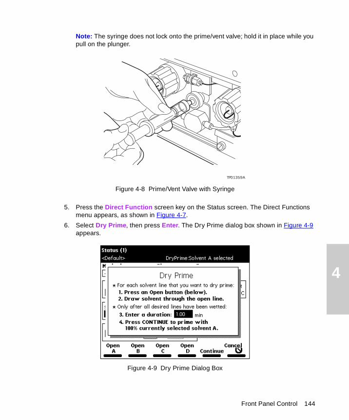
4
Note: The syringe does not lock onto the prime/vent valve; hold it in place while you pull on the plunger.
Figure 4-8 Prime/Vent Valve with Syringe
5. Press the Direct Function screen key on the Status screen. The Direct Functions menu appears, as shown in Figure 4-7.
6. Select Dry Prime, then press Enter. The Dry Prime dialog box shown in Figure 4-9 appears.
Figure 4-9 Dry Prime Dialog Box
TP01359A
Front Panel Control 144
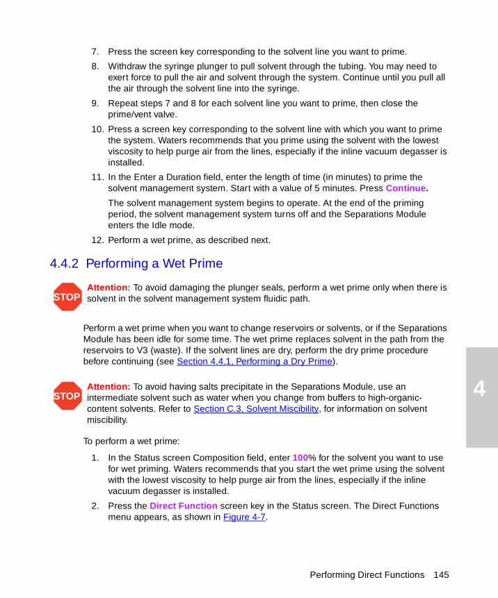
4
7. Press the screen key corresponding to the solvent line you want to prime.
8. Withdraw the syringe plunger to pull solvent through the tubing. You may need to exert force to pull the air and solvent through the system. Continue until you pull all the air through the solvent line into the syringe.
9. Repeat steps 7 and 8 for each solvent line you want to prime, then close the prime/vent valve.
10. Press a screen key corresponding to the solvent line with which you want to prime the system. Waters recommends that you prime using the solvent with the lowest viscosity to help purge air from the lines, especially if the inline vacuum degasser is installed.
11. In the Enter a Duration field, enter the length of time (in minutes) to prime the solvent management system. Start with a value of 5 minutes. Press Continue.
The solvent management system begins to operate. At the end of the priming period, the solvent management system turns off and the Separations Module enters the Idle mode.
12. Perform a wet prime, as described next.
4.4.2 Performing a Wet Prime
Perform a wet prime when you want to change reservoirs or solvents, or if the Separations Module has been idle for some time. The wet prime replaces solvent in the path from the reservoirs to V3 (waste). If the solvent lines are dry, perform the dry prime procedure before continuing (see Section 4.4.1, Performing a Dry Prime).
To perform a wet prime:
1. In the Status screen Composition field, enter 100% for the solvent you want to use for wet priming. Waters recommends that you start the wet prime using the solvent with the lowest viscosity to help purge air from the lines, especially if the inline vacuum degasser is installed.
2. Press the Direct Function screen key in the Status screen. The Direct Functions menu appears, as shown in Figure 4-7.
STOPAttention: To avoid damaging the plunger seals, perform a wet prime only when there is solvent in the solvent management system fluidic path.
STOPAttention: To avoid having salts precipitate in the Separations Module, use an intermediate solvent such as water when you change from buffers to high-organic-content solvents. Refer to Section C.3, Solvent Miscibility, for information on solvent miscibility.
Performing Direct Functions 145
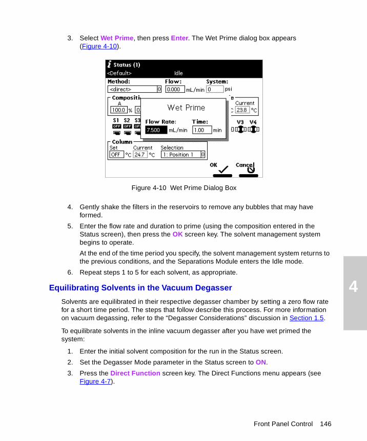
4
3. Select Wet Prime, then press Enter. The Wet Prime dialog box appears (Figure 4-10).
Figure 4-10 Wet Prime Dialog Box
4. Gently shake the filters in the reservoirs to remove any bubbles that may have formed.
5. Enter the flow rate and duration to prime (using the composition entered in the Status screen), then press the OK screen key. The solvent management system begins to operate.
At the end of the time period you specify, the solvent management system returns to the previous conditions, and the Separations Module enters the Idle mode.
6. Repeat steps 1 to 5 for each solvent, as appropriate.
Equilibrating Solvents in the Vacuum Degasser
Solvents are equilibrated in their respective degasser chamber by setting a zero flow rate for a short time period. The steps that follow describe this process. For more information on vacuum degassing, refer to the “Degasser Considerations” discussion in Section 1.5.
To equilibrate solvents in the inline vacuum degasser after you have wet primed the system:
1. Enter the initial solvent composition for the run in the Status screen.
2. Set the Degasser Mode parameter in the Status screen to ON.
3. Press the Direct Function screen key. The Direct Functions menu appears (see Figure 4-7).
Front Panel Control 146
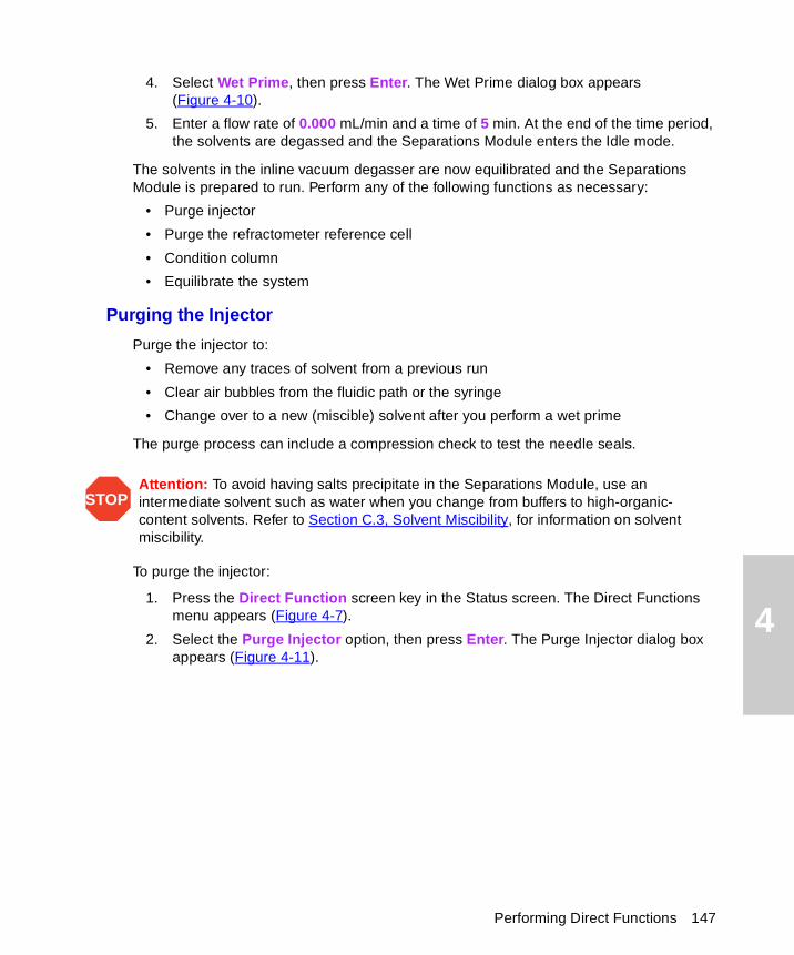
4
4. Select Wet Prime, then press Enter. The Wet Prime dialog box appears (Figure 4-10).
5. Enter a flow rate of 0.000 mL/min and a time of 5 min. At the end of the time period, the solvents are degassed and the Separations Module enters the Idle mode.
The solvents in the inline vacuum degasser are now equilibrated and the Separations Module is prepared to run. Perform any of the following functions as necessary:
• Purge injector
• Purge the refractometer reference cell
• Condition column
• Equilibrate the system
Purging the Injector
Purge the injector to:
• Remove any traces of solvent from a previous run
• Clear air bubbles from the fluidic path or the syringe
• Change over to a new (miscible) solvent after you perform a wet prime
The purge process can include a compression check to test the needle seals.
To purge the injector:
1. Press the Direct Function screen key in the Status screen. The Direct Functions menu appears (Figure 4-7).
2. Select the Purge Injector option, then press Enter. The Purge Injector dialog box appears (Figure 4-11).
STOPAttention: To avoid having salts precipitate in the Separations Module, use an intermediate solvent such as water when you change from buffers to high-organic-content solvents. Refer to Section C.3, Solvent Miscibility, for information on solvent miscibility.
Performing Direct Functions 147
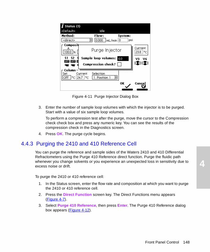
4
Figure 4-11 Purge Injector Dialog Box
3. Enter the number of sample loop volumes with which the injector is to be purged. Start with a value of six sample loop volumes.
To perform a compression test after the purge, move the cursor to the Compression check check box and press any numeric key. You can see the results of the compression check in the Diagnostics screen.
4. Press OK. The purge cycle begins.
4.4.3 Purging the 2410 and 410 Reference Cell
You can purge the reference and sample sides of the Waters 2410 and 410 Differential Refractometers using the Purge 410 Reference direct function. Purge the fluidic path whenever you change solvents or you experience an unexpected loss in sensitivity due to excess noise or drift.
To purge the 2410 or 410 reference cell:
1. In the Status screen, enter the flow rate and composition at which you want to purge the 2410 or 410 reference cell.
2. Press the Direct Function screen key. The Direct Functions menu appears (Figure 4-7).
3. Select Purge 410 Reference, then press Enter. The Purge 410 Reference dialog box appears (Figure 4-12).
Front Panel Control 148
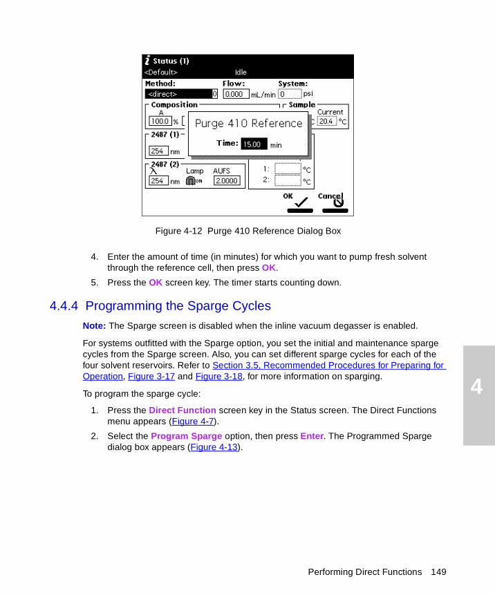
4
Figure 4-12 Purge 410 Reference Dialog Box
4. Enter the amount of time (in minutes) for which you want to pump fresh solvent through the reference cell, then press OK.
5. Press the OK screen key. The timer starts counting down.
4.4.4 Programming the Sparge Cycles
Note: The Sparge screen is disabled when the inline vacuum degasser is enabled.
For systems outfitted with the Sparge option, you set the initial and maintenance sparge cycles from the Sparge screen. Also, you can set different sparge cycles for each of the four solvent reservoirs. Refer to Section 3.5, Recommended Procedures for Preparing for Operation, Figure 3-17 and Figure 3-18, for more information on sparging.
To program the sparge cycle:
1. Press the Direct Function screen key in the Status screen. The Direct Functions menu appears (Figure 4-7).
2. Select the Program Sparge option, then press Enter. The Programmed Sparge dialog box appears (Figure 4-13).
Performing Direct Functions 149
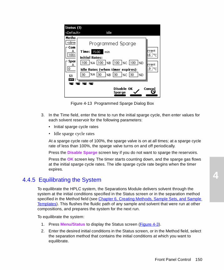
4
Figure 4-13 Programmed Sparge Dialog Box
3. In the Time field, enter the time to run the initial sparge cycle, then enter values for each solvent reservoir for the following parameters:
• Initial sparge cycle rates
• Idle sparge cycle rates
At a sparge cycle rate of 100%, the sparge valve is on at all times; at a sparge cycle rate of less than 100%, the sparge valve turns on and off periodically.
Press the Disable Sparge screen key if you do not want to sparge the reservoirs.
Press the OK screen key. The timer starts counting down, and the sparge gas flows at the initial sparge cycle rates. The idle sparge cycle rate begins when the timer expires.
4.4.5 Equilibrating the System
To equilibrate the HPLC system, the Separations Module delivers solvent through the system at the initial conditions specified in the Status screen or in the separation method specified in the Method field (see Chapter 6, Creating Methods, Sample Sets, and Sample Templates). This flushes the fluidic path of any sample and solvent that were run at other compositions, and prepares the system for the next run.
To equilibrate the system:
1. Press Menu/Status to display the Status screen (Figure 4-3).
2. Enter the desired initial conditions in the Status screen, or in the Method field, select the separation method that contains the initial conditions at which you want to equilibrate.
Front Panel Control 150
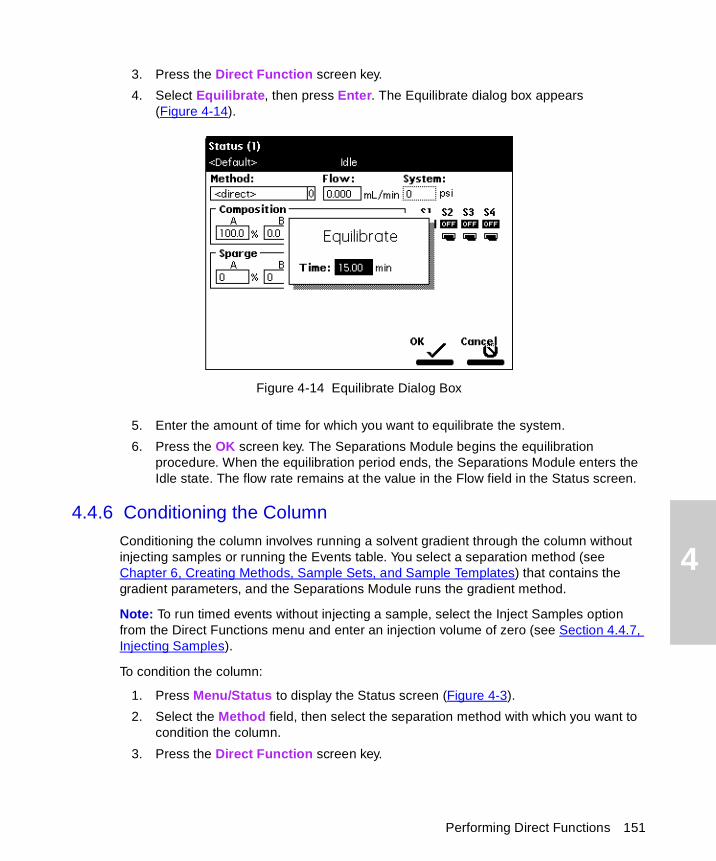
4
3. Press the Direct Function screen key.
4. Select Equilibrate, then press Enter. The Equilibrate dialog box appears (Figure 4-14).
Figure 4-14 Equilibrate Dialog Box
5. Enter the amount of time for which you want to equilibrate the system.
6. Press the OK screen key. The Separations Module begins the equilibration procedure. When the equilibration period ends, the Separations Module enters the Idle state. The flow rate remains at the value in the Flow field in the Status screen.
4.4.6 Conditioning the Column
Conditioning the column involves running a solvent gradient through the column without injecting samples or running the Events table. You select a separation method (see Chapter 6, Creating Methods, Sample Sets, and Sample Templates) that contains the gradient parameters, and the Separations Module runs the gradient method.
Note: To run timed events without injecting a sample, select the Inject Samples option from the Direct Functions menu and enter an injection volume of zero (see Section 4.4.7, Injecting Samples).
To condition the column:
1. Press Menu/Status to display the Status screen (Figure 4-3).
2. Select the Method field, then select the separation method with which you want to condition the column.
3. Press the Direct Function screen key.
Performing Direct Functions 151
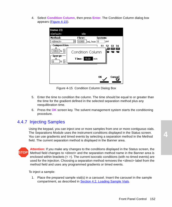
4
4. Select Condition Column, then press Enter. The Condition Column dialog box appears (Figure 4-15).
Figure 4-15 Condition Column Dialog Box
5. Enter the time to condition the column. The time should be equal to or greater than the time for the gradient defined in the selected separation method plus any reequilibration time.
6. Press the OK screen key. The solvent management system starts the conditioning procedure.
4.4.7 Injecting Samples
Using the keypad, you can inject one or more samples from one or more contiguous vials. The Separations Module uses the instrument conditions displayed in the Status screen. You can use gradients and timed events by selecting a separation method in the Method field. The current separation method is displayed in the Banner area.
To inject a sample:
1. Place the prepared sample vial(s) in a carousel. Insert the carousel in the sample compartment, as described in Section 4.2, Loading Sample Vials.
STOPAttention: If you make any changes to the conditions displayed in the Status screen, the Method field changes to <direct> and the separation method name in the Banner area is enclosed within brackets (< >). The current isocratic conditions (with no timed events) are used for the injection. Choosing a separation method removes the <direct> label from the method field and uses any programmed gradients or timed events.
Front Panel Control 152
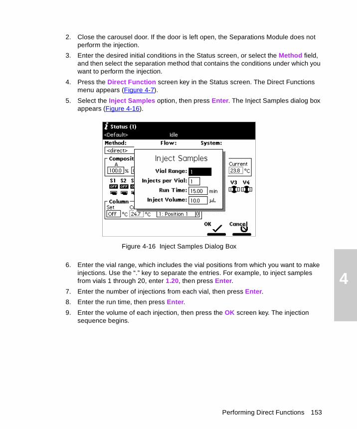
4
2. Close the carousel door. If the door is left open, the Separations Module does not perform the injection.
3. Enter the desired initial conditions in the Status screen, or select the Method field, and then select the separation method that contains the conditions under which you want to perform the injection.
4. Press the Direct Function screen key in the Status screen. The Direct Functions menu appears (Figure 4-7).
5. Select the Inject Samples option, then press Enter. The Inject Samples dialog box appears (Figure 4-16).
Figure 4-16 Inject Samples Dialog Box
6. Enter the vial range, which includes the vial positions from which you want to make injections. Use the “.” key to separate the entries. For example, to inject samples from vials 1 through 20, enter 1.20, then press Enter.
7. Enter the number of injections from each vial, then press Enter.
8. Enter the run time, then press Enter.
9. Enter the volume of each injection, then press the OK screen key. The injection sequence begins.
Performing Direct Functions 153
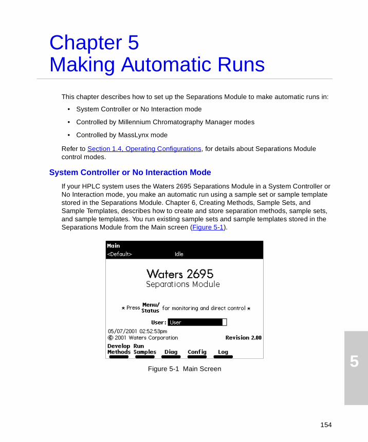
5
Chapter 5Making Automatic Runs
This chapter describes how to set up the Separations Module to make automatic runs in:
• System Controller or No Interaction mode
• Controlled by Millennium Chromatography Manager modes
• Controlled by MassLynx mode
Refer to Section 1.4, Operating Configurations, for details about Separations Module control modes.
System Controller or No Interaction Mode
If your HPLC system uses the Waters 2695 Separations Module in a System Controller or No Interaction mode, you make an automatic run using a sample set or sample template stored in the Separations Module. Chapter 6, Creating Methods, Sample Sets, and Sample Templates, describes how to create and store separation methods, sample sets, and sample templates. You run existing sample sets and sample templates stored in the Separations Module from the Main screen (Figure 5-1).
Figure 5-1 Main Screen
154
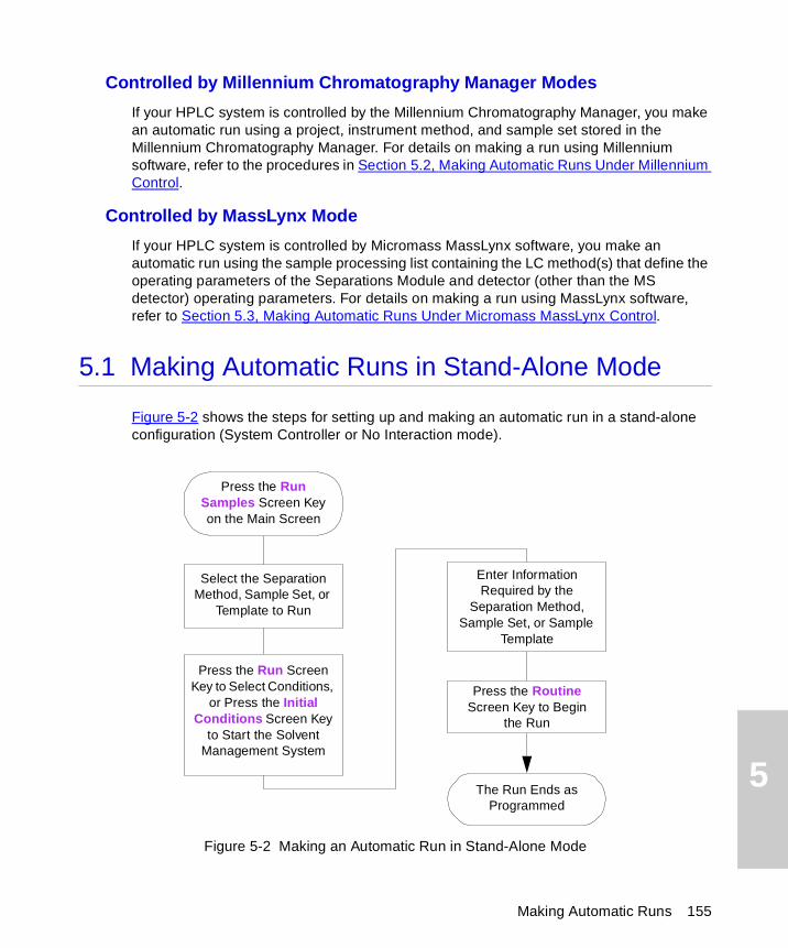
5
Controlled by Millennium Chromatography Manager Modes
If your HPLC system is controlled by the Millennium Chromatography Manager, you make an automatic run using a project, instrument method, and sample set stored in the Millennium Chromatography Manager. For details on making a run using Millennium software, refer to the procedures in Section 5.2, Making Automatic Runs Under Millennium Control.
Controlled by MassLynx Mode
If your HPLC system is controlled by Micromass MassLynx software, you make an automatic run using the sample processing list containing the LC method(s) that define the operating parameters of the Separations Module and detector (other than the MS detector) operating parameters. For details on making a run using MassLynx software, refer to Section 5.3, Making Automatic Runs Under Micromass MassLynx Control.
5.1 Making Automatic Runs in Stand-Alone Mode
Figure 5-2 shows the steps for setting up and making an automatic run in a stand-alone configuration (System Controller or No Interaction mode).
Figure 5-2 Making an Automatic Run in Stand-Alone Mode
Press the Run Samples Screen Key on the Main Screen
Enter Information Required by the
Separation Method, Sample Set, or Sample
Template
Press the Run Screen Key to Select Conditions,
or Press the Initial Conditions Screen Key
to Start the Solvent Management System
The Run Ends as Programmed
Select the Separation Method, Sample Set, or
Template to Run
Press the Routine Screen Key to Begin
the Run
Making Automatic Runs 155
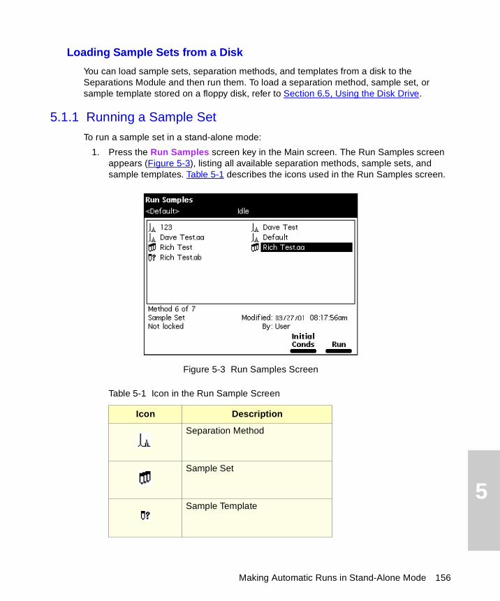
5
Loading Sample Sets from a Disk
You can load sample sets, separation methods, and templates from a disk to the Separations Module and then run them. To load a separation method, sample set, or sample template stored on a floppy disk, refer to Section 6.5, Using the Disk Drive.
5.1.1 Running a Sample Set
To run a sample set in a stand-alone mode:
1. Press the Run Samples screen key in the Main screen. The Run Samples screen appears (Figure 5-3), listing all available separation methods, sample sets, and sample templates. Table 5-1 describes the icons used in the Run Samples screen.
Figure 5-3 Run Samples Screen
Table 5-1 Icon in the Run Sample Screen
Icon Description
Separation Method
Sample Set
Sample Template
Making Automatic Runs in Stand-Alone Mode 156
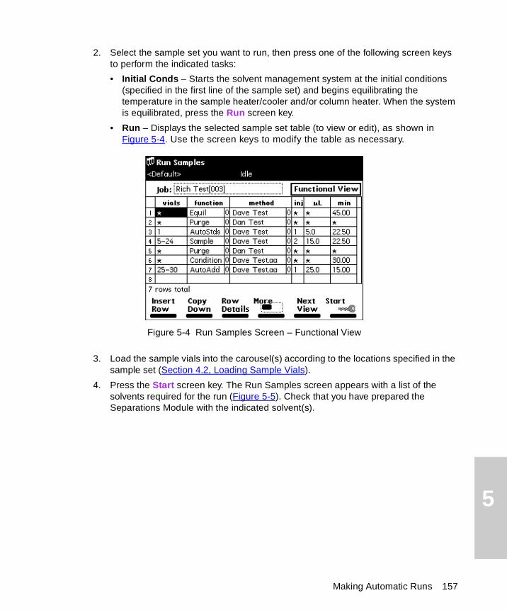
5
2. Select the sample set you want to run, then press one of the following screen keys to perform the indicated tasks:
• Initial Conds – Starts the solvent management system at the initial conditions (specified in the first line of the sample set) and begins equilibrating the temperature in the sample heater/cooler and/or column heater. When the system is equilibrated, press the Run screen key.
• Run – Displays the selected sample set table (to view or edit), as shown in Figure 5-4. Use the screen keys to modify the table as necessary.
Figure 5-4 Run Samples Screen – Functional View
3. Load the sample vials into the carousel(s) according to the locations specified in the sample set (Section 4.2, Loading Sample Vials).
4. Press the Start screen key. The Run Samples screen appears with a list of the solvents required for the run (Figure 5-5). Check that you have prepared the Separations Module with the indicated solvent(s).
Making Automatic Runs 157
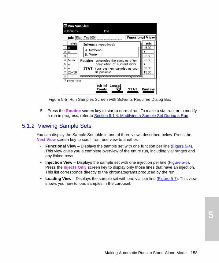
5
Figure 5-5 Run Samples Screen with Solvents Required Dialog Box
5. Press the Routine screen key to start a normal run. To make a stat run, or to modify a run in progress, refer to Section 5.1.4, Modifying a Sample Set During a Run.
5.1.2 Viewing Sample Sets
You can display the Sample Set table in one of three views described below. Press the Next View screen key to scroll from one view to another.
• Functional View – Displays the sample set with one function per line (Figure 5-4). This view gives you a complete overview of the entire run, including vial ranges and any linked rows.
• Injection View – Displays the sample set with one injection per line (Figure 5-6). Press the Injects Only screen key to display only those lines that have an injection. This list corresponds directly to the chromatograms produced by the run.
• Loading View – Displays the sample set with one vial per line (Figure 5-7). This view shows you how to load samples in the carousel.
Making Automatic Runs in Stand-Alone Mode 158
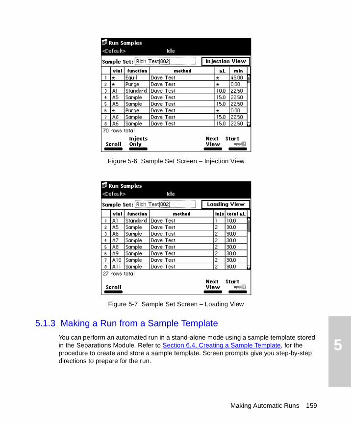
5
Figure 5-6 Sample Set Screen – Injection View
Figure 5-7 Sample Set Screen – Loading View
5.1.3 Making a Run from a Sample Template
You can perform an automated run in a stand-alone mode using a sample template stored in the Separations Module. Refer to Section 6.4, Creating a Sample Template, for the procedure to create and store a sample template. Screen prompts give you step-by-step directions to prepare for the run.
Making Automatic Runs 159

5
To run a sample template in a stand-alone mode:
1. Press the Run Samples screen key in the Main screen. The Run Samples screen appears (Figure 5-3).
2. Select the sample template you want to run, then press Enter. The Setup dialog box appears (Figure 5-8).
Figure 5-8 Setup Dialog Box
3. Enter the number of samples to run, then press the Continue screen key.
4. Enter the location of the first sample vial, then press the Continue screen key. You must use consecutive sample vials on one or more carousels.
5. Repeat steps 3 and 4 if the sample template includes multiple separation methods.
6. Enter the number of standards in the run, then press the Continue screen key.
7. Enter the location of the first standard vial, then press the Continue screen key. You must use consecutive standard vials.
8. Make sure that the solvents listed in the dialog box are primed and in the appropriate inlet tubes, then press the Start screen key.
5.1.4 Modifying a Sample Set During a Run
You can modify operating conditions during a run in a stand-alone mode by:
• Using the stat run function
• Editing the separation method
Making Automatic Runs in Stand-Alone Mode 160

5
Performing a Stat Run
You can use the stat run function to interrupt a run in progress and perform one or more injections after the current injection is done, then continue with the scheduled run. Performing a stat run is most useful when running separation methods that use identical solvents and temperatures.
To perform a stat run while a sample set is running:
1. Load the sample(s) into the carousel, then place the carousel in the sample compartment.
2. Press the Run Samples screen key in the Main screen. The Run Samples screen appears (Figure 5-3).
3. Select the separation method or sample set you want to use for the stat run, then press the Run screen key.
4. Enter the carousel position of the vial(s) and other parameters in the appropriate fields in the screen.
5. Press the Start screen key. A screen appears with a list of the solvents required for the run, as shown in Figure 5-5. Check that you have prepared the Separations Module with the indicated solvent(s).
6. Press the Stat screen key. The stat run starts immediately after the current injection is complete. The original sample set resumes after the stat run is complete.
Editing a Separation Method
You can modify a separation method while a sample set is running. If the separation method is being used for the current injection, the current injection is not affected by the changes. You must save the changes to the modified separation method before you can apply the method to all subsequent injections that use that separation method. Use the procedures in Section 6.1, Creating and Editing Separation Methods, to modify and save the separation method.
5.1.5 Stopping a Run
To stop a run in progress, press one of the following keys from the Status screen:
• Stop Inject (screen key) – Stops the current injection and displays a dialog box requesting you to abort or resume the injection
• Hold Inject (screen key) – Completes the current function, suspends operation of subsequent functions, and displays screen keys that allow you to abort or resume the sample set
• Hold Gradient (screen key) – Holds the current gradient conditions. A screen key allows you to resume the gradient
Making Automatic Runs 161
5
• Stop Flow (on the keypad) – Stops the flow of solvent, suspends operation of the current function, and displays screen keys that allow you to abort or resume the function
If any alarm condition specified in the separation method, sample set, or sample template is set to “Stop Function” or “Stop Flow” and the alarm condition occurs, a dialog box appears notifying you of the alarm condition. The following screen keys are in this dialog box:
• Abort – Cancels the current function
• Resume – Resumes the current function
5.2 Making Automatic Runs Under Millennium Control
If your Separations Module is configured for Millennium Chromatography Manager control (Millennium version 2.xx or Millennium32), you make an automatic run from Run Samples in the Millennium software. When the Separations Module is running under Millennium control, the word “Remote” appears in the banner area. Configure your Separations Module for Millennium Chromatography Manager control as described in Section 3.2.2, Configuring the Operating Mode.
Making an Automatic Run Using Millennium Software
To make an automatic run, perform the following steps at the Millennium workstation:
1. Create a chromatographic system that includes the Waters 2695 Separations Module:
• For Millennium software version 2.xx, create a system that includes the 2695 solvent management and sample management systems (using two IEEE-488 addresses). Refer to the Millennium documentation for information on creating a chromatographic system.
• For Millennium32 software, create a system that includes the Waters 2695 Separations Module (using one IEEE-488 address). Refer to the Millennium Help for information on creating a chromatographic system.
Note: The 2695 Separations Module is recognized as a 2690 Separations Module by Millennium version 2.xx and Millennium32 versions 3.2 and earlier.
2. Create a Millennium instrument method that uses the system you created in step 1. Refer to the Millennium documentation for information on creating and/or modifying an instrument method.
Making Automatic Runs Under Millennium Control 162
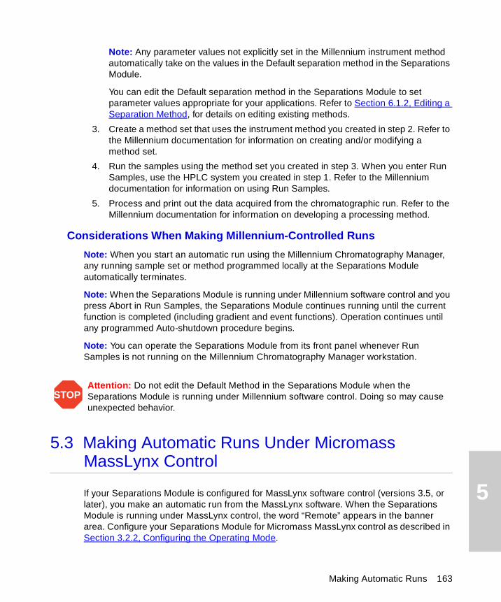
5
Note: Any parameter values not explicitly set in the Millennium instrument method automatically take on the values in the Default separation method in the Separations Module.
You can edit the Default separation method in the Separations Module to set parameter values appropriate for your applications. Refer to Section 6.1.2, Editing a Separation Method, for details on editing existing methods.
3. Create a method set that uses the instrument method you created in step 2. Refer to the Millennium documentation for information on creating and/or modifying a method set.
4. Run the samples using the method set you created in step 3. When you enter Run Samples, use the HPLC system you created in step 1. Refer to the Millennium documentation for information on using Run Samples.
5. Process and print out the data acquired from the chromatographic run. Refer to the Millennium documentation for information on developing a processing method.
Considerations When Making Millennium-Controlled Runs
Note: When you start an automatic run using the Millennium Chromatography Manager, any running sample set or method programmed locally at the Separations Module automatically terminates.
Note: When the Separations Module is running under Millennium software control and you press Abort in Run Samples, the Separations Module continues running until the current function is completed (including gradient and event functions). Operation continues until any programmed Auto-shutdown procedure begins.
Note: You can operate the Separations Module from its front panel whenever Run Samples is not running on the Millennium Chromatography Manager workstation.
5.3 Making Automatic Runs Under Micromass MassLynx Control
If your Separations Module is configured for MassLynx software control (versions 3.5, or later), you make an automatic run from the MassLynx software. When the Separations Module is running under MassLynx control, the word “Remote” appears in the banner area. Configure your Separations Module for Micromass MassLynx control as described in Section 3.2.2, Configuring the Operating Mode.
STOPAttention: Do not edit the Default Method in the Separations Module when the Separations Module is running under Millennium software control. Doing so may cause unexpected behavior.
Making Automatic Runs 163
5
Making an Automatic Run Using MassLynx Software
To make an automatic run, perform the following steps at the Micromass MassLynx computer:
1. Configure an LC/MS system that includes the Separations Module. Refer to MassLynx Help for information on configuring an inlet system.
2. From the Inlet Editor, create an LC method for the Separations Module and detector (other than the mass spectrometer). Refer to MassLynx Help for information on using the Inlet Editor.
3. Acquire a single sample from the Inlet Editor. To acquire multiple samples, create a sample processing list from the MassLynx Top Level screen. Refer to MassLynx Help for information on sample processing lists and acquisition.
4. Process and print out the data acquired from the chromatographic run. Refer to MassLynx Help for information on processing data.
You can operate the Separations Module from its front panel whenever MassLynx is not running.
Making Automatic Runs Under Micromass MassLynx Control 164

6
Chapter 6Creating Methods, Sample Sets, and Sample TemplatesChapter 5, Making Automatic Runs, describes how to perform an automatic run in either a stand-alone or remote control mode.
This chapter describes how to create and store the separation methods, sample sets, and sample templates that allow you to make automatic runs when the Separations Module is in the stand-alone System Controller mode. You can store up to 60 methods in the internal memory of the Separations Module.
Note: When the number of stored methods approaches the maximum (60), the time to create and save methods increases from a few seconds to over 30 seconds. When 60 methods have been stored, a warning message appears, indicating that memory capacity has been reached.
The Separations Module supports three types of tools for controlling automatic runs in a stand-alone mode:
• Separation methods
• Sample sets
• Sample templates
Separation Methods
The Separations Module uses and stores programs that can automatically run a separation method. A separation method consists of time-based and nontime-based conditions that influence the separation, including:
• Mobile phase composition and flow rate
• Sample temperature
• Column temperature
• I/O parameters
When you run a separation method on another, identically configured Separations Module in an Alliance® System, you can reproduce identical separations.
165
6
Sample Sets
A sample set applies functions to separation methods. Examples of functions include (inject) sample, purge, prime, and equilibrate. When you combine a function with a separation method, the resulting sample set tells the Separations Module what to do, when to do it, and under what conditions. You can use multiple separation methods in a sample set.
Sample Templates
Sample templates allow you to preprogram a sample set so the operator needs only to enter the number and location of samples and standards. The sample template then prompts the operator to load and prime the correct solvents for the sample set. As with any sample set, the sample template can use multiple separation methods.
Sample templates are useful in regulatory-compliant laboratories where standard operating procedures are used. Senior personnel can develop, program, and lock the sample template to prevent any unauthorized changes to the sample template. Once the operator has prepared the Separations Module according to the directions on the screen, the sample template can run unattended.
6.1 Creating and Editing Separation Methods
You create and edit separation methods using the Methods screen and six method parameter screens. From the Methods screen, you can:
• Create a new separation method
• Edit an existing separation method
• Copy and then edit an existing method
• Lock a separation method to prevent changes
• Create a sample template
Figure 6-1 shows the steps to create and edit separation methods using the front panel of the Separations Module. If your HPLC system is under Millennium software control, refer to the Millennium documentation for the procedures to create and edit method sets in the Millennium Chromatography Manager. If your HPLC system is under MassLynx software control, refer to MassLynx Help for details on using the Inlet Editor to create an LC method.
Creating Methods, Sample Sets, and Sample Templates 166
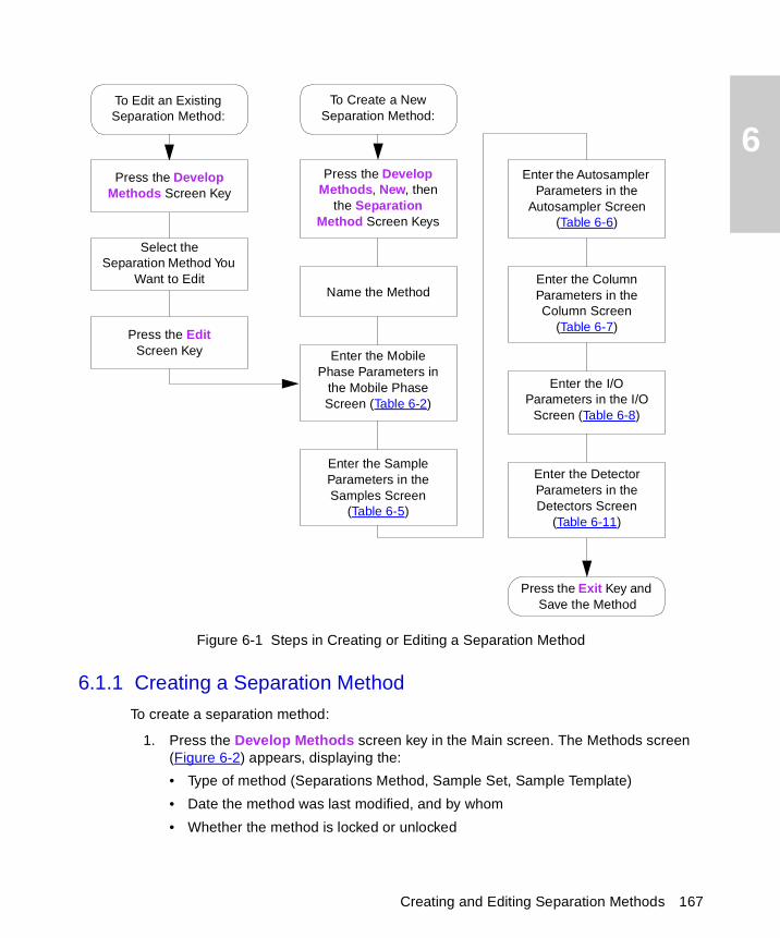
6
Figure 6-1 Steps in Creating or Editing a Separation Method
6.1.1 Creating a Separation Method
To create a separation method:
1. Press the Develop Methods screen key in the Main screen. The Methods screen (Figure 6-2) appears, displaying the:
• Type of method (Separations Method, Sample Set, Sample Template)
• Date the method was last modified, and by whom
• Whether the method is locked or unlocked
To Create a NewSeparation Method:
Enter the Mobile Phase Parameters in
the Mobile Phase Screen (Table 6-2)
Enter the Sample Parameters in the Samples Screen
(Table 6-5)
Enter the Autosampler Parameters in the
Autosampler Screen (Table 6-6)
Enter the Column Parameters in the Column Screen
(Table 6-7)
Enter the I/O Parameters in the I/O
Screen (Table 6-8)
Enter the Detector Parameters in the Detectors Screen
(Table 6-11)
Press the Develop Methods, New, then
the Separation Method Screen Keys
Name the Method
Press the Develop Methods Screen Key
To Edit an ExistingSeparation Method:
Select the Separation Method You
Want to Edit
Press the Exit Key and Save the Method
Press the Edit Screen Key
Creating and Editing Separation Methods 167
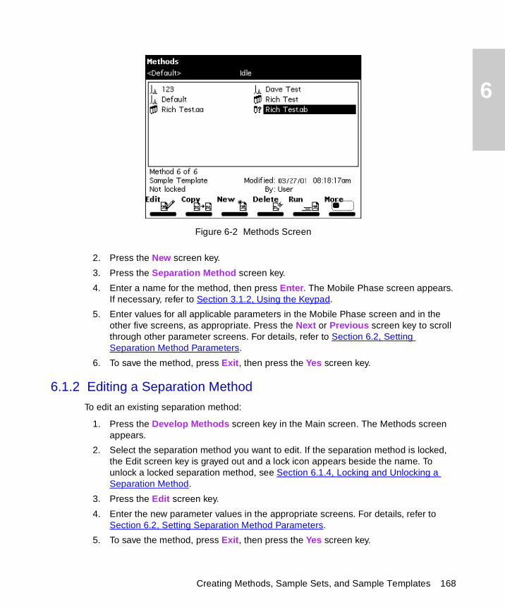
6
Figure 6-2 Methods Screen
2. Press the New screen key.
3. Press the Separation Method screen key.
4. Enter a name for the method, then press Enter. The Mobile Phase screen appears. If necessary, refer to Section 3.1.2, Using the Keypad.
5. Enter values for all applicable parameters in the Mobile Phase screen and in the other five screens, as appropriate. Press the Next or Previous screen key to scroll through other parameter screens. For details, refer to Section 6.2, Setting Separation Method Parameters.
6. To save the method, press Exit, then press the Yes screen key.
6.1.2 Editing a Separation Method
To edit an existing separation method:
1. Press the Develop Methods screen key in the Main screen. The Methods screen appears.
2. Select the separation method you want to edit. If the separation method is locked, the Edit screen key is grayed out and a lock icon appears beside the name. To unlock a locked separation method, see Section 6.1.4, Locking and Unlocking a Separation Method.
3. Press the Edit screen key.
4. Enter the new parameter values in the appropriate screens. For details, refer to Section 6.2, Setting Separation Method Parameters.
5. To save the method, press Exit, then press the Yes screen key.
Creating Methods, Sample Sets, and Sample Templates 168
6
6.1.3 Copying and Editing a Separation Method
To copy and edit an existing separation method, leaving the original method unchanged:
1. Press the Develop Methods screen key in the Main screen. The Methods screen appears.
2. Select the separation method you want to copy.
3. Press the Copy screen key.
4. Enter the name of the new method in the dialog box that appears, then press Enter.
Note: The Separations Module automatically adds the appropriate method extension.
5. Enter the new parameter values in the appropriate screens. Refer to Section 6.2, Setting Separation Method Parameters, for details.
6. To save the method, press Exit, then press the Yes screen key.
6.1.4 Locking and Unlocking a Separation Method
To prevent changes to a separation method, you can lock the method. To lock a separation method:
1. Press the Develop Methods screen key in the Main screen. The Methods screen appears.
2. Select the method you want to lock, then press the Lock screen key.
3. Enter a key word in the dialog box that appears, then press Enter. You can use up to 30 alphanumeric characters. The method is locked and cannot be changed, deleted, or renamed until it is unlocked. If necessary, refer to Section 3.1.2, Using the Keypad.
4. Record the key word and keep it in a safe place.
To unlock the current method:
1. Press the Develop Methods screen key in the Main screen. The Methods screen appears.
2. Select the method you want to unlock, then press the Unlock screen key.
3. Enter the key word in the dialog box that appears, then press Enter. The method is unlocked.
Creating and Editing Separation Methods 169
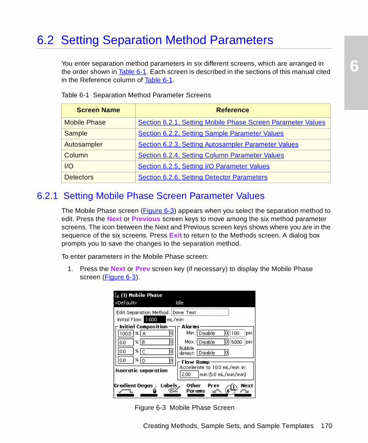
6
Creating Methods, Sample Sets, and Sample Templates 170
6.2 Setting Separation Method Parameters
You enter separation method parameters in six different screens, which are arranged in the order shown in Table 6-1. Each screen is described in the sections of this manual cited in the Reference column of Table 6-1.
6.2.1 Setting Mobile Phase Screen Parameter Values
The Mobile Phase screen (Figure 6-3) appears when you select the separation method to edit. Press the Next or Previous screen keys to move among the six method parameter screens. The icon between the Next and Previous screen keys shows where you are in the sequence of the six screens. Press Exit to return to the Methods screen. A dialog box prompts you to save the changes to the separation method.
To enter parameters in the Mobile Phase screen:
1. Press the Next or Prev screen key (if necessary) to display the Mobile Phase screen (Figure 6-3).
Figure 6-3 Mobile Phase Screen
Table 6-1 Separation Method Parameter Screens
Screen Name Reference
Mobile Phase Section 6.2.1, Setting Mobile Phase Screen Parameter Values
Sample Section 6.2.2, Setting Sample Parameter Values
Autosampler Section 6.2.3, Setting Autosampler Parameter Values
Column Section 6.2.4, Setting Column Parameter Values
I/O Section 6.2.5, Setting I/O Parameter Values
Detectors Section 6.2.6, Setting Detector Parameters
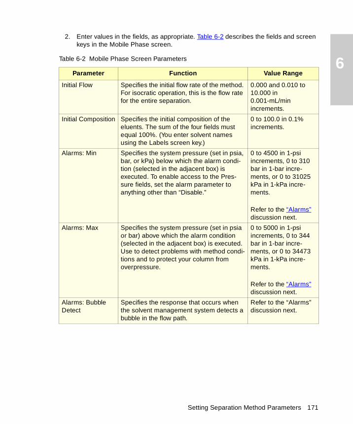
6
2. Enter values in the fields, as appropriate. Table 6-2 describes the fields and screen keys in the Mobile Phase screen.
Table 6-2 Mobile Phase Screen Parameters
Parameter Function Value Range
Initial Flow Specifies the initial flow rate of the method. For isocratic operation, this is the flow rate for the entire separation.
0.000 and 0.010 to 10.000 in 0.001-mL/min increments.
Initial Composition Specifies the initial composition of the eluents. The sum of the four fields must equal 100%. (You enter solvent names using the Labels screen key.)
0 to 100.0 in 0.1% increments.
Alarms: Min Specifies the system pressure (set in psia, bar, or kPa) below which the alarm condi-tion (selected in the adjacent box) is executed. To enable access to the Pres-sure fields, set the alarm parameter to anything other than “Disable.”
0 to 4500 in 1-psi increments, 0 to 310 bar in 1-bar incre-ments, or 0 to 31025 kPa in 1-kPa incre-ments.
Refer to the “Alarms” discussion next.
Alarms: Max Specifies the system pressure (set in psia or bar) above which the alarm condition (selected in the adjacent box) is executed. Use to detect problems with method condi-tions and to protect your column from overpressure.
0 to 5000 in 1-psi increments, 0 to 344 bar in 1-bar incre-ments, or 0 to 34473 kPa in 1-kPa incre-ments.
Refer to the “Alarms” discussion next.
Alarms: Bubble Detect
Specifies the response that occurs when the solvent management system detects a bubble in the flow path.
Refer to the “Alarms” discussion next.
Setting Separation Method Parameters 171
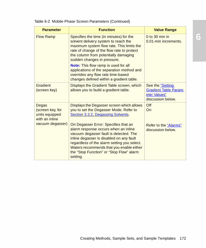
6
Flow Ramp Specifies the time (in minutes) for the solvent delivery system to reach the maximum system flow rate. This limits the rate of change of the flow rate to protect the column from potentially damaging sudden changes in pressure.Note: This flow ramp is used for all applications of the separation method and overrides any flow rate time-based changes defined within a gradient table.
0 to 30 min in 0.01-min increments.
Gradient(screen key)
Displays the Gradient Table screen, which allows you to build a gradient table.
See the “Setting Gradient Table Param-eter Values” discussion below.
Degas(screen key, for units equipped with an inline vacuum degasser)
Displays the Degasser screen which allows you to set the Degasser Mode. Refer to Section 3.3.2, Degassing Solvents.
On Degasser Error: Specifies that an alarm response occurs when an inline vacuum degasser fault is detected. The inline degasser is disabled on any fault regardless of the alarm setting you select. Waters recommends that you enable either the “Stop Function” or “Stop Flow” alarm setting.
OffOn
Refer to the “Alarms” discussion below.
Table 6-2 Mobile Phase Screen Parameters (Continued)
Parameter Function Value Range
Creating Methods, Sample Sets, and Sample Templates 172

6
Sparge Rate(screen key, for units equipped with a sparge valve)Displays the Sparge dialog box, which allows you to set the initial and mainte-nance sparge rates for each reservoir, and the amount of time to sparge at the initial rate.
Labels(screen key)
Displays the Solvents dialog box, which allows you to add, remove, or change the names of solvents used in methods.Use the Add, Remove, and Change screen keys to edit the list of solvents.
Note: A, B, C, and D are not valid user-entered solvent names.
Table 6-2 Mobile Phase Screen Parameters (Continued)
Parameter Function Value Range
MethanolMethanol/Water
THFWater
Setting Separation Method Parameters 173
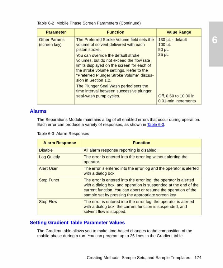
6
Alarms
The Separations Module maintains a log of all enabled errors that occur during operation. Each error can produce a variety of responses, as shown in Table 6-3.
Setting Gradient Table Parameter Values
The Gradient table allows you to make time-based changes to the composition of the mobile phase during a run. You can program up to 25 lines in the Gradient table.
Other Params(screen key)
The Preferred Stroke Volume field sets the volume of solvent delivered with each piston stroke. You can override the default stroke volumes, but do not exceed the flow rate limits displayed on the screen for each of the stroke volume settings. Refer to the “Preferred Plunger Stroke Volume” discus-sion in Section 1.2.The Plunger Seal Wash period sets the time interval between successive plunger seal-wash pump cycles.
130 µL - default100 uL50 µL25 µL
Off, 0.50 to 10.00 in 0.01-min increments
Table 6-3 Alarm Responses
Alarm Response Function
Disable All alarm response reporting is disabled.
Log Quietly The error is entered into the error log without alerting the operator.
Alert User The error is entered into the error log and the operator is alerted with a dialog box.
Stop Funct The error is entered into the error log, the operator is alerted with a dialog box, and operation is suspended at the end of the current function. You can abort or resume the operation of the sample set by pressing the appropriate screen key.
Stop Flow The error is entered into the error log, the operator is alerted with a dialog box, the current function is suspended, and solvent flow is stopped.
Table 6-2 Mobile Phase Screen Parameters (Continued)
Parameter Function Value Range
Creating Methods, Sample Sets, and Sample Templates 174
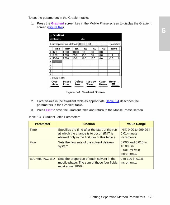
6
To set the parameters in the Gradient table:
1. Press the Gradient screen key in the Mobile Phase screen to display the Gradient screen (Figure 6-4).
Figure 6-4 Gradient Screen
2. Enter values in the Gradient table as appropriate. Table 6-4 describes the parameters in the Gradient table.
3. Press Exit to save the Gradient table and return to the Mobile Phase screen.
Table 6-4 Gradient Table Parameters
Parameter Function Value Range
Time Specifies the time after the start of the run at which the change is to occur. (INIT is allowed only in the first row of this table.)
INIT, 0.00 to 999.99 in 0.01-minute increments.
Flow Sets the flow rate of the solvent delivery system.
0.000 and 0.010 to 10.000 in 0.001-mL/min increments.
%A, %B, %C, %D Sets the proportion of each solvent in the mobile phase. The sum of these four fields must equal 100%.
0 to 100 in 0.1% increments.
Setting Separation Method Parameters 175
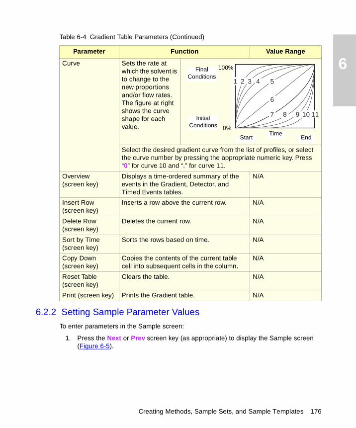
6
6.2.2 Setting Sample Parameter Values
To enter parameters in the Sample screen:
1. Press the Next or Prev screen key (as appropriate) to display the Sample screen (Figure 6-5).
Curve Sets the rate at which the solvent is to change to the new proportions and/or flow rates. The figure at right shows the curve shape for each value.
Select the desired gradient curve from the list of profiles, or select the curve number by pressing the appropriate numeric key. Press “0” for curve 10 and “.” for curve 11.
Overview (screen key)
Displays a time-ordered summary of the events in the Gradient, Detector, and Timed Events tables.
N/A
Insert Row (screen key)
Inserts a row above the current row. N/A
Delete Row (screen key)
Deletes the current row. N/A
Sort by Time (screen key)
Sorts the rows based on time. N/A
Copy Down (screen key)
Copies the contents of the current table cell into subsequent cells in the column.
N/A
Reset Table(screen key)
Clears the table. N/A
Print (screen key) Prints the Gradient table. N/A
Table 6-4 Gradient Table Parameters (Continued)
Parameter Function Value Range
2 3 4 5
6
8 9 10 117
1
Start End
Initial Conditions
Final Conditions
Time
100%
0%
Creating Methods, Sample Sets, and Sample Templates 176
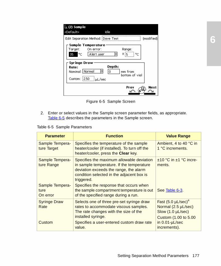
6
Figure 6-5 Sample Screen
2. Enter or select values in the Sample screen parameter fields, as appropriate. Table 6-5 describes the parameters in the Sample screen.
Table 6-5 Sample Parameters
Parameter Function Value Range
Sample Tempera-ture Target
Specifies the temperature of the sample heater/cooler (if installed). To turn off the heater/cooler, press the Clear key.
Ambient, 4 to 40 °C in 1 °C increments.
Sample Tempera-ture Range
Sample Tempera-tureOn error
Specifies the maximum allowable deviation in sample temperature. If the temperature deviation exceeds the range, the alarm condition selected in the adjacent box is triggered.Specifies the response that occurs when the sample compartment temperature is out of the specified range during a run.
±10 °C in ±1 °C incre-ments.
See Table 6-3.
Syringe Draw Rate
Custom
Selects one of three pre-set syringe draw rates to accommodate viscous samples. The rate changes with the size of the installed syringe.Specifies a user-entered custom draw rate value.
Fast (5.0 µL/sec)a
Normal (2.5 µL/sec)Slow (1.0 µL/sec)Custom (1.00 to 5.00 in 0.01-µL/sec increments).
Setting Separation Method Parameters 177
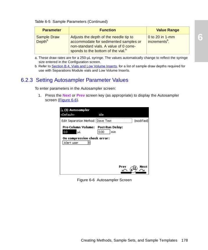
6
6.2.3 Setting Autosampler Parameter Values
To enter parameters in the Autosampler screen:
1. Press the Next or Prev screen key (as appropriate) to display the Autosampler screen (Figure 6-6).
Figure 6-6 Autosampler Screen
Sample Draw Depthb
Adjusts the depth of the needle tip to accommodate for sedimented samples or non-standard vials. A value of 0 corre-sponds to the bottom of the vial.b
0 to 20 in 1-mm incrementsb.
a. These draw rates are for a 250-µL syringe. The values automatically change to reflect the syringe size entered in the Configuration screen.
b. Refer to Section B.4, Vials and Low Volume Inserts, for a list of sample draw depths required for use with Separations Module vials and Low Volume Inserts.
Table 6-5 Sample Parameters (Continued)
Parameter Function Value Range
Creating Methods, Sample Sets, and Sample Templates 178
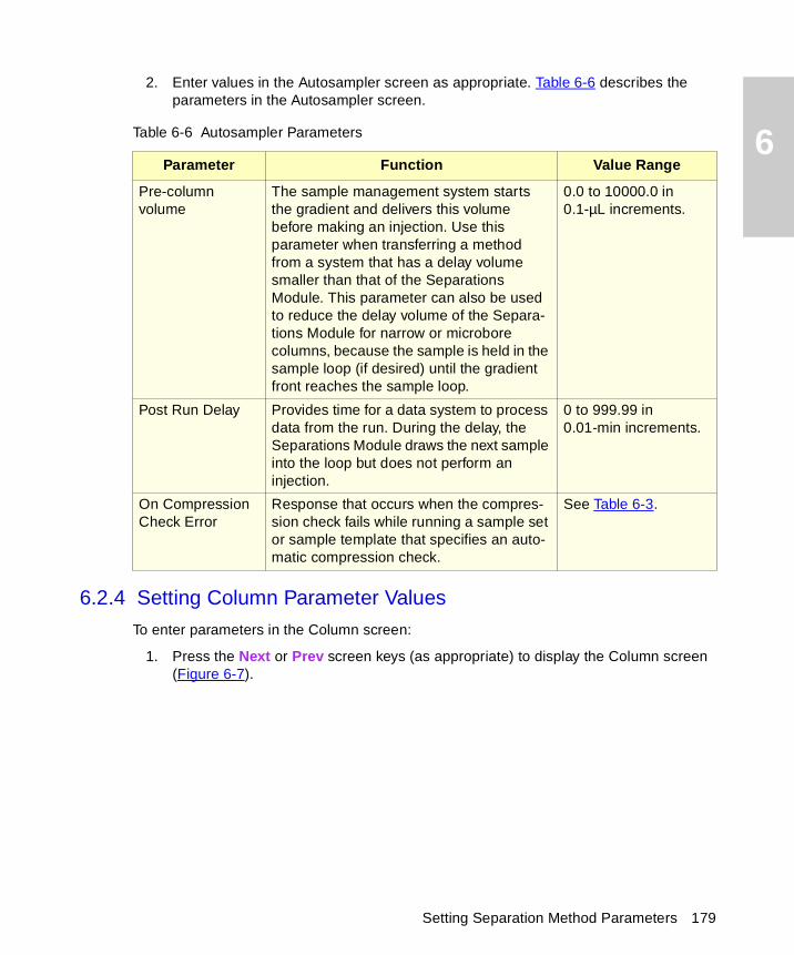
6
2. Enter values in the Autosampler screen as appropriate. Table 6-6 describes the parameters in the Autosampler screen.
6.2.4 Setting Column Parameter Values
To enter parameters in the Column screen:
1. Press the Next or Prev screen keys (as appropriate) to display the Column screen (Figure 6-7).
Table 6-6 Autosampler Parameters
Parameter Function Value Range
Pre-column volume
The sample management system starts the gradient and delivers this volume before making an injection. Use this parameter when transferring a method from a system that has a delay volume smaller than that of the Separations Module. This parameter can also be used to reduce the delay volume of the Separa-tions Module for narrow or microbore columns, because the sample is held in the sample loop (if desired) until the gradient front reaches the sample loop.
0.0 to 10000.0 in 0.1-µL increments.
Post Run Delay Provides time for a data system to process data from the run. During the delay, the Separations Module draws the next sample into the loop but does not perform an injection.
0 to 999.99 in 0.01-min increments.
On Compression Check Error
Response that occurs when the compres-sion check fails while running a sample set or sample template that specifies an auto-matic compression check.
See Table 6-3.
Setting Separation Method Parameters 179
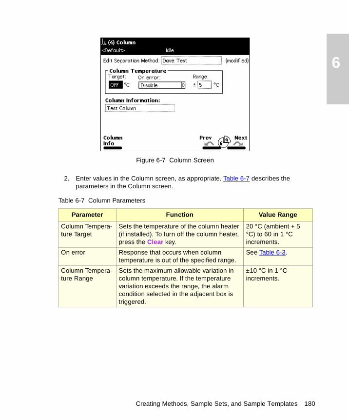
6
Figure 6-7 Column Screen
2. Enter values in the Column screen, as appropriate. Table 6-7 describes the parameters in the Column screen.
Table 6-7 Column Parameters
Parameter Function Value Range
Column Tempera-ture Target
Sets the temperature of the column heater (if installed). To turn off the column heater, press the Clear key.
20 °C (ambient + 5 °C) to 60 in 1 °C increments.
On error Response that occurs when column temperature is out of the specified range.
See Table 6-3.
Column Tempera-ture Range
Sets the maximum allowable variation in column temperature. If the temperature variation exceeds the range, the alarm condition selected in the adjacent box is triggered.
±10 °C in 1 °C increments.
Creating Methods, Sample Sets, and Sample Templates 180
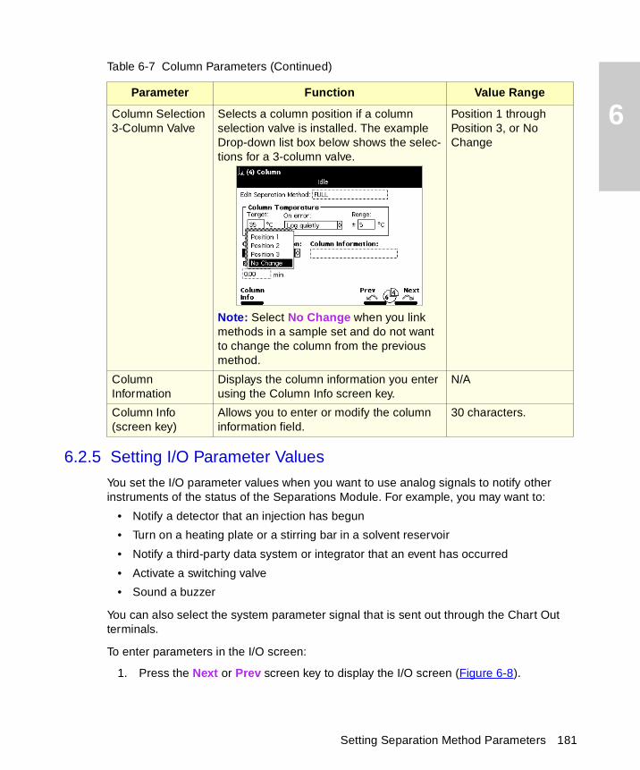
6
6.2.5 Setting I/O Parameter Values
You set the I/O parameter values when you want to use analog signals to notify other instruments of the status of the Separations Module. For example, you may want to:
• Notify a detector that an injection has begun
• Turn on a heating plate or a stirring bar in a solvent reservoir
• Notify a third-party data system or integrator that an event has occurred
• Activate a switching valve
• Sound a buzzer
You can also select the system parameter signal that is sent out through the Chart Out terminals.
To enter parameters in the I/O screen:
1. Press the Next or Prev screen key to display the I/O screen (Figure 6-8).
Column Selection3-Column Valve
Selects a column position if a column selection valve is installed. The example Drop-down list box below shows the selec-tions for a 3-column valve.
Note: Select No Change when you link methods in a sample set and do not want to change the column from the previous method.
Position 1 through Position 3, or No Change
Column Information
Displays the column information you enter using the Column Info screen key.
N/A
Column Info (screen key)
Allows you to enter or modify the column information field.
30 characters.
Table 6-7 Column Parameters (Continued)
Parameter Function Value Range
Setting Separation Method Parameters 181
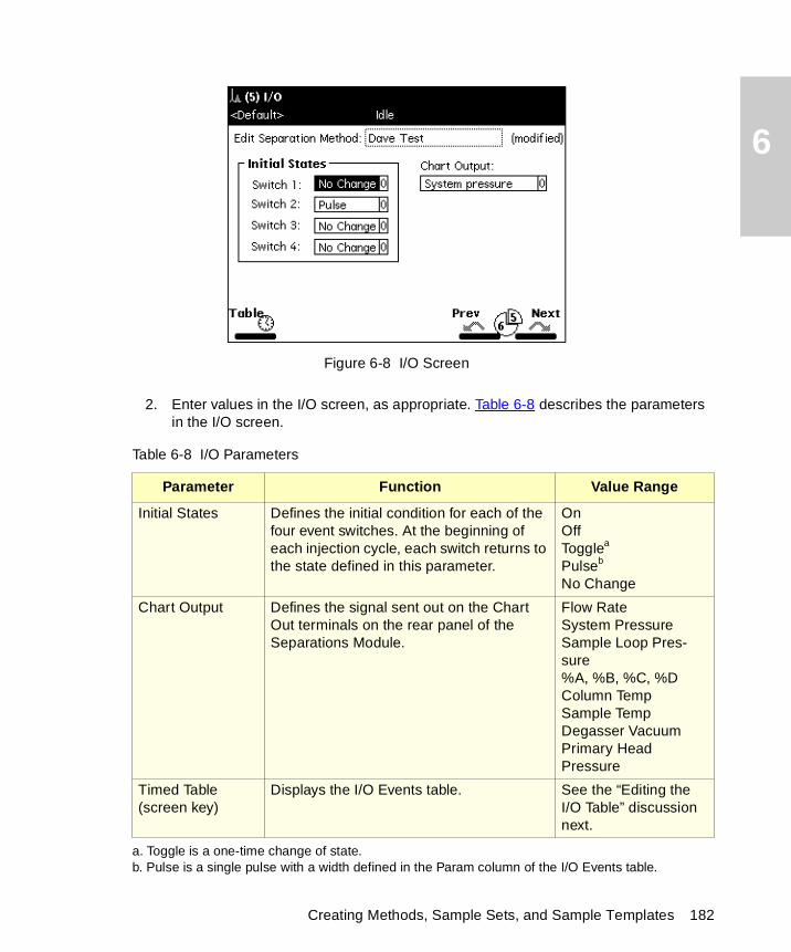
6
Figure 6-8 I/O Screen
2. Enter values in the I/O screen, as appropriate. Table 6-8 describes the parameters in the I/O screen.
Table 6-8 I/O Parameters
Parameter Function Value Range
Initial States Defines the initial condition for each of the four event switches. At the beginning of each injection cycle, each switch returns to the state defined in this parameter.
OnOffTogglea
Pulseb
No Change
a. Toggle is a one-time change of state.b. Pulse is a single pulse with a width defined in the Param column of the I/O Events table.
Chart Output Defines the signal sent out on the Chart Out terminals on the rear panel of the Separations Module.
Flow RateSystem PressureSample Loop Pres-sure%A, %B, %C, %DColumn TempSample TempDegasser VacuumPrimary Head Pressure
Timed Table (screen key)
Displays the I/O Events table. See the “Editing the I/O Table” discussion next.
Creating Methods, Sample Sets, and Sample Templates 182
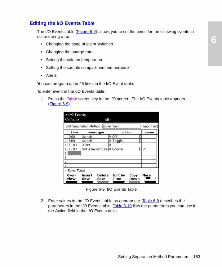
6
Editing the I/O Events Table
The I/O Events table (Figure 6-9) allows you to set the times for the following events to occur during a run:
• Changing the state of event switches
• Changing the sparge rate
• Setting the column temperature
• Setting the sample compartment temperature
• Alerts
You can program up to 25 lines in the I/O Event table.
To enter event in the I/O Events table:
1. Press the Table screen key in the I/O screen. The I/O Events table appears (Figure 6-9).
Figure 6-9 I/O Events Table
2. Enter values in the I/O Events table as appropriate. Table 6-9 describes the parameters in the I/O Events table. Table 6-10 lists the parameters you can use in the Action field in the I/O Events table.
Setting Separation Method Parameters 183
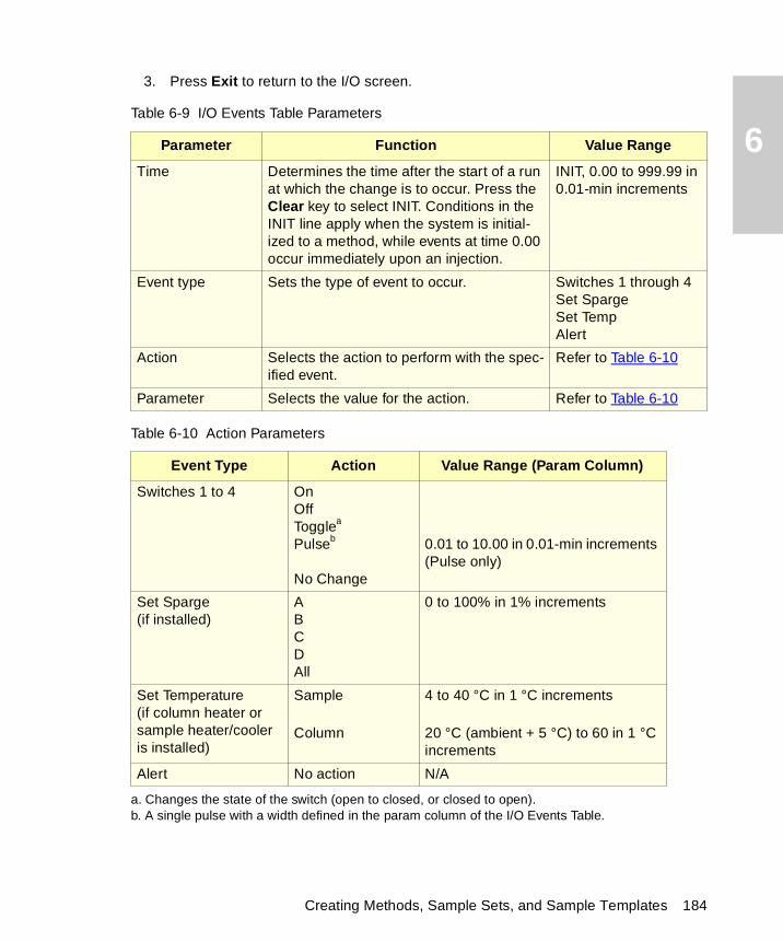
6
3. Press Exit to return to the I/O screen.
Table 6-9 I/O Events Table Parameters
Parameter Function Value Range
Time Determines the time after the start of a run at which the change is to occur. Press the Clear key to select INIT. Conditions in the INIT line apply when the system is initial-ized to a method, while events at time 0.00 occur immediately upon an injection.
INIT, 0.00 to 999.99 in 0.01-min increments
Event type Sets the type of event to occur. Switches 1 through 4Set SpargeSet TempAlert
Action Selects the action to perform with the spec-ified event.
Refer to Table 6-10
Parameter Selects the value for the action. Refer to Table 6-10
Table 6-10 Action Parameters
Event Type Action Value Range (Param Column)
Switches 1 to 4 OnOffTogglea
Pulseb
No Change
a. Changes the state of the switch (open to closed, or closed to open).b. A single pulse with a width defined in the param column of the I/O Events Table.
0.01 to 10.00 in 0.01-min increments (Pulse only)
Set Sparge(if installed)
ABCDAll
0 to 100% in 1% increments
Set Temperature(if column heater or sample heater/cooler is installed)
Sample
Column
4 to 40 °C in 1 °C increments
20 °C (ambient + 5 °C) to 60 in 1 °C increments
Alert No action N/A
Creating Methods, Sample Sets, and Sample Templates 184
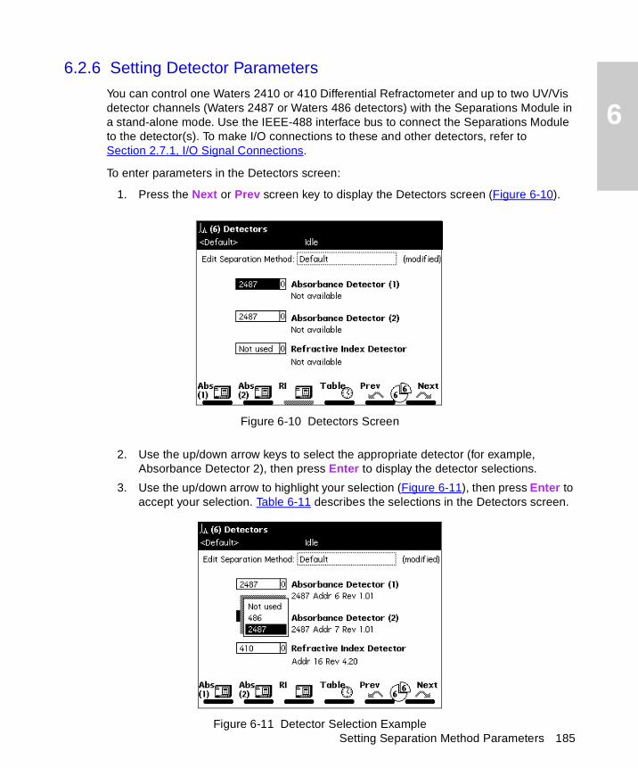
6
Setting Separation Method Parameters 185
6.2.6 Setting Detector Parameters
You can control one Waters 2410 or 410 Differential Refractometer and up to two UV/Vis detector channels (Waters 2487 or Waters 486 detectors) with the Separations Module in a stand-alone mode. Use the IEEE-488 interface bus to connect the Separations Module to the detector(s). To make I/O connections to these and other detectors, refer to Section 2.7.1, I/O Signal Connections.
To enter parameters in the Detectors screen:
1. Press the Next or Prev screen key to display the Detectors screen (Figure 6-10).
Figure 6-10 Detectors Screen
2. Use the up/down arrow keys to select the appropriate detector (for example, Absorbance Detector 2), then press Enter to display the detector selections.
3. Use the up/down arrow to highlight your selection (Figure 6-11), then press Enter to accept your selection. Table 6-11 describes the selections in the Detectors screen.
Figure 6-11 Detector Selection Example
6
4. To enter control parameters for Waters detectors, refer to the “Setting Absorbance Parameters” and “Setting RI Parameters” discussions that follow.
Setting Absorbance Parameters
To enter control parameters for a 2487 or 486 UV/Vis detector:
1. Press the Abs (1) or Abs (2) screen key to display the appropriate absorbance detector screen. Figure 6-12 shows the screen for a Waters 2487 Detector; Figure 6-13 shows the screen for a Waters 486 Detector.
2. Enter detector parameters as required. Table 6-12 lists the parameters for a Waters 2487 Detector; Table 6-13 lists the parameters for a Waters 486 Detector.
3. Press the OK screen key to accept your settings.
4. For steps on programming detector events, refer to the “Editing the Detector Table” discussion in this chapter.
Table 6-11 Detector Selections
Parameter Function Selections
Absorbance Detector (1)
Enables a Waters 2487 or 486 UV/Vis Detector channel.
2487, 486, or Not used
Absorbance Detector (2)
Enables a second Waters 2487 or 486 UV/Vis Detector channel.
2487, 486, or Not used
Refractive Index Detector 410
Enables a Waters 2410 or 410 Differential Refractometer.
410 or Not used
Absorbance (1) (screen key)
Displays the 2487 or 486 TUV screen (Figure 6-13).
See Table 6-13
Absorbance (2) (screen key)
Displays the second 2487 or second 486 TUV screen (Figure 6-13).
See Table 6-13
RI (screen key) Displays the 2410/410 RI screen (Figure 6-14).
See Table 6-13
Table (screen key) Displays the Detector Table (Figure 6-15). See Table 6-15
Creating Methods, Sample Sets, and Sample Templates 186

6
Figure 6-12 2487(1) UV/Vis Detector Screen
Table 6-12 2487 UV/Vis Parameters
Parameter Function Value Range
λ (wavelength) Sets the wavelength of the detector. 190 to 700 in 1-nm increments
Sensitivity Sets the sensitivity of the detector. 0.0001 to 4.0000 in 0.0001-AU increments
Filter Sets the time constant of the filter in the detector.
0.1 to 99.0 in 0.1-sec increments
Polarity Selects the output of the 2487 to create positive or negative peaks.
+, –
Auto zero on inject Resets the output of the 2487 to 0 volts when the injection begins.
Selected or dese-lected
Setting Separation Method Parameters 187
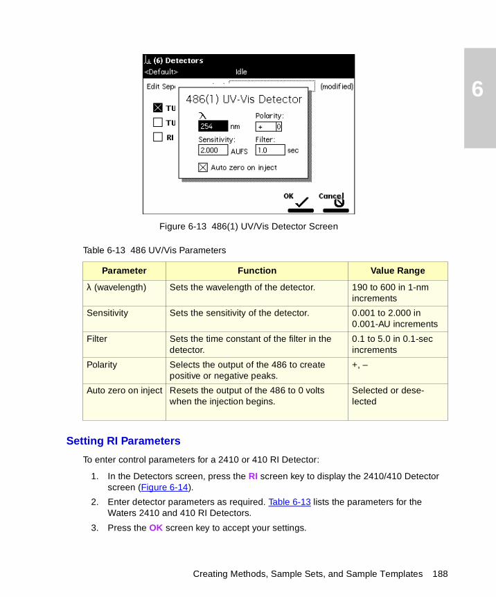
6
Figure 6-13 486(1) UV/Vis Detector Screen
Setting RI Parameters
To enter control parameters for a 2410 or 410 RI Detector:
1. In the Detectors screen, press the RI screen key to display the 2410/410 Detector screen (Figure 6-14).
2. Enter detector parameters as required. Table 6-13 lists the parameters for the Waters 2410 and 410 RI Detectors.
3. Press the OK screen key to accept your settings.
Table 6-13 486 UV/Vis Parameters
Parameter Function Value Range
λ (wavelength) Sets the wavelength of the detector. 190 to 600 in 1-nm increments
Sensitivity Sets the sensitivity of the detector. 0.001 to 2.000 in 0.001-AU increments
Filter Sets the time constant of the filter in the detector.
0.1 to 5.0 in 0.1-sec increments
Polarity Selects the output of the 486 to create positive or negative peaks.
+, –
Auto zero on inject Resets the output of the 486 to 0 volts when the injection begins.
Selected or dese-lected
Creating Methods, Sample Sets, and Sample Templates 188
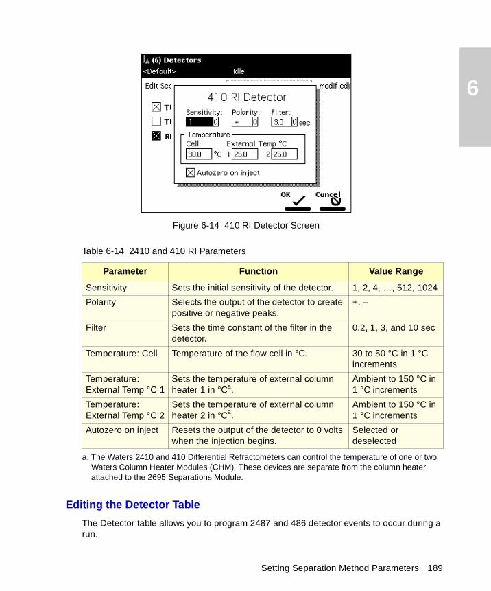
6
Figure 6-14 410 RI Detector Screen
Editing the Detector Table
The Detector table allows you to program 2487 and 486 detector events to occur during a run.
Table 6-14 2410 and 410 RI Parameters
Parameter Function Value Range
Sensitivity Sets the initial sensitivity of the detector. 1, 2, 4, …, 512, 1024
Polarity Selects the output of the detector to create positive or negative peaks.
+, –
Filter Sets the time constant of the filter in the detector.
0.2, 1, 3, and 10 sec
Temperature: Cell Temperature of the flow cell in °C. 30 to 50 °C in 1 °C increments
Temperature: External Temp °C 1
Sets the temperature of external column heater 1 in °Ca.
a. The Waters 2410 and 410 Differential Refractometers can control the temperature of one or two Waters Column Heater Modules (CHM). These devices are separate from the column heater attached to the 2695 Separations Module.
Ambient to 150 °C in 1 °C increments
Temperature: External Temp °C 2
Sets the temperature of external column heater 2 in °Ca.
Ambient to 150 °C in 1 °C increments
Autozero on inject Resets the output of the detector to 0 volts when the injection begins.
Selected or deselected
Setting Separation Method Parameters 189
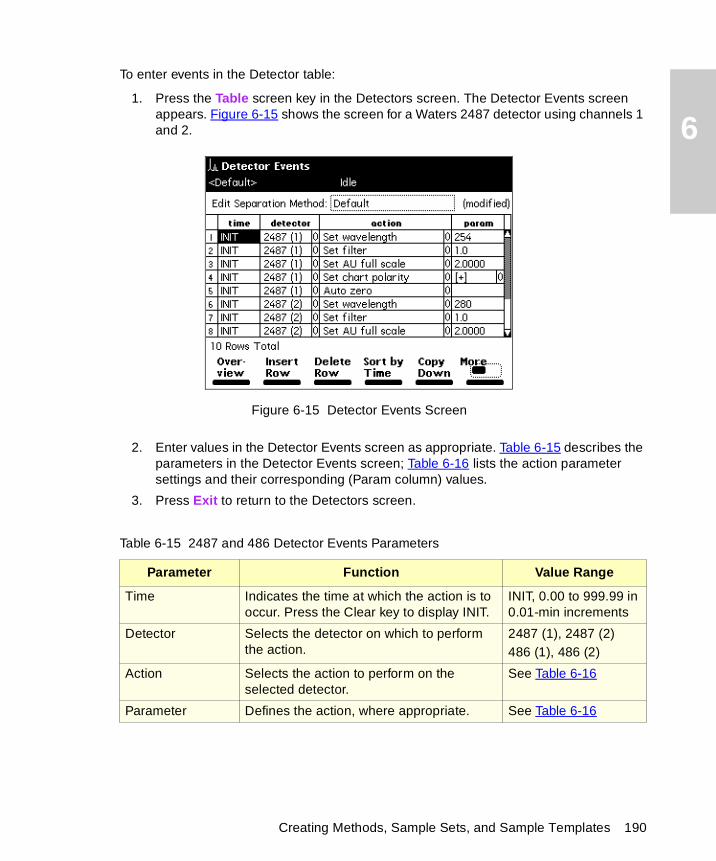
6
To enter events in the Detector table:
1. Press the Table screen key in the Detectors screen. The Detector Events screen appears. Figure 6-15 shows the screen for a Waters 2487 detector using channels 1 and 2.
Figure 6-15 Detector Events Screen
2. Enter values in the Detector Events screen as appropriate. Table 6-15 describes the parameters in the Detector Events screen; Table 6-16 lists the action parameter settings and their corresponding (Param column) values.
3. Press Exit to return to the Detectors screen.
Table 6-15 2487 and 486 Detector Events Parameters
Parameter Function Value Range
Time Indicates the time at which the action is to occur. Press the Clear key to display INIT.
INIT, 0.00 to 999.99 in 0.01-min increments
Detector Selects the detector on which to perform the action.
2487 (1), 2487 (2)486 (1), 486 (2)
Action Selects the action to perform on the selected detector.
See Table 6-16
Parameter Defines the action, where appropriate. See Table 6-16
Creating Methods, Sample Sets, and Sample Templates 190
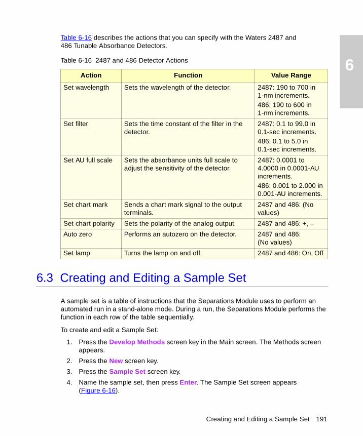
6
Table 6-16 describes the actions that you can specify with the Waters 2487 and 486 Tunable Absorbance Detectors.
6.3 Creating and Editing a Sample Set
A sample set is a table of instructions that the Separations Module uses to perform an automated run in a stand-alone mode. During a run, the Separations Module performs the function in each row of the table sequentially.
To create and edit a Sample Set:
1. Press the Develop Methods screen key in the Main screen. The Methods screen appears.
2. Press the New screen key.
3. Press the Sample Set screen key.
4. Name the sample set, then press Enter. The Sample Set screen appears (Figure 6-16).
Table 6-16 2487 and 486 Detector Actions
Action Function Value Range
Set wavelength Sets the wavelength of the detector. 2487: 190 to 700 in 1-nm increments.486: 190 to 600 in 1-nm increments.
Set filter Sets the time constant of the filter in the detector.
2487: 0.1 to 99.0 in 0.1-sec increments.486: 0.1 to 5.0 in 0.1-sec increments.
Set AU full scale Sets the absorbance units full scale to adjust the sensitivity of the detector.
2487: 0.0001 to 4.0000 in 0.0001-AU increments.486: 0.001 to 2.000 in 0.001-AU increments.
Set chart mark Sends a chart mark signal to the output terminals.
2487 and 486: (No values)
Set chart polarity Sets the polarity of the analog output. 2487 and 486: +, –
Auto zero Performs an autozero on the detector. 2487 and 486:(No values)
Set lamp Turns the lamp on and off. 2487 and 486: On, Off
Creating and Editing a Sample Set 191
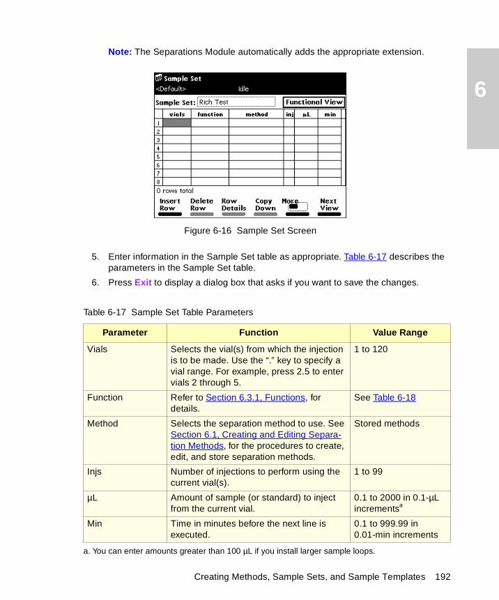
6
Note: The Separations Module automatically adds the appropriate extension.
Figure 6-16 Sample Set Screen
5. Enter information in the Sample Set table as appropriate. Table 6-17 describes the parameters in the Sample Set table.
6. Press Exit to display a dialog box that asks if you want to save the changes.
Table 6-17 Sample Set Table Parameters
Parameter Function Value Range
Vials Selects the vial(s) from which the injection is to be made. Use the “.” key to specify a vial range. For example, press 2.5 to enter vials 2 through 5.
1 to 120
Function Refer to Section 6.3.1, Functions, for details.
See Table 6-18
Method Selects the separation method to use. See Section 6.1, Creating and Editing Separa-tion Methods, for the procedures to create, edit, and store separation methods.
Stored methods
Injs Number of injections to perform using the current vial(s).
1 to 99
µL Amount of sample (or standard) to inject from the current vial.
0.1 to 2000 in 0.1-µL incrementsa
a. You can enter amounts greater than 100 µL if you install larger sample loops.
Min Time in minutes before the next line is executed.
0.1 to 999.99 in 0.01-min increments
Creating Methods, Sample Sets, and Sample Templates 192
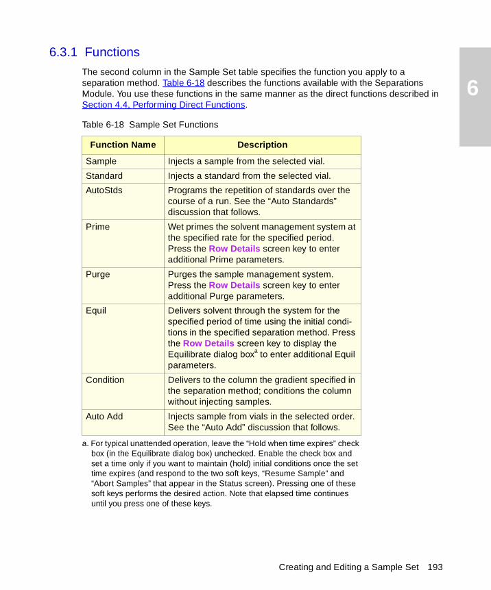
6
6.3.1 Functions
The second column in the Sample Set table specifies the function you apply to a separation method. Table 6-18 describes the functions available with the Separations Module. You use these functions in the same manner as the direct functions described in Section 4.4, Performing Direct Functions.
Table 6-18 Sample Set Functions
Function Name Description
Sample Injects a sample from the selected vial.
Standard Injects a standard from the selected vial.
AutoStds Programs the repetition of standards over the course of a run. See the “Auto Standards” discussion that follows.
Prime Wet primes the solvent management system at the specified rate for the specified period. Press the Row Details screen key to enter additional Prime parameters.
Purge Purges the sample management system. Press the Row Details screen key to enter additional Purge parameters.
Equil Delivers solvent through the system for the specified period of time using the initial condi-tions in the specified separation method. Press the Row Details screen key to display the Equilibrate dialog boxa to enter additional Equil parameters.
a. For typical unattended operation, leave the “Hold when time expires” check box (in the Equilibrate dialog box) unchecked. Enable the check box and set a time only if you want to maintain (hold) initial conditions once the set time expires (and respond to the two soft keys, “Resume Sample” and “Abort Samples” that appear in the Status screen). Pressing one of these soft keys performs the desired action. Note that elapsed time continues until you press one of these keys.
Condition Delivers to the column the gradient specified in the separation method; conditions the column without injecting samples.
Auto Add Injects sample from vials in the selected order. See the “Auto Add” discussion that follows.
Creating and Editing a Sample Set 193
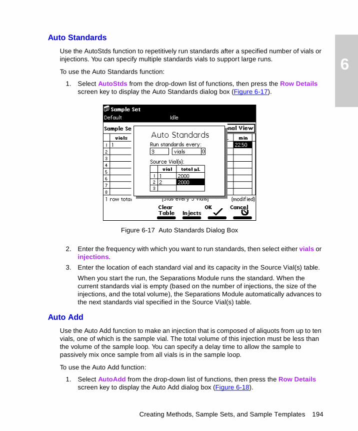
6
Auto Standards
Use the AutoStds function to repetitively run standards after a specified number of vials or injections. You can specify multiple standards vials to support large runs.
To use the Auto Standards function:
1. Select AutoStds from the drop-down list of functions, then press the Row Details screen key to display the Auto Standards dialog box (Figure 6-17).
Figure 6-17 Auto Standards Dialog Box
2. Enter the frequency with which you want to run standards, then select either vials or injections.
3. Enter the location of each standard vial and its capacity in the Source Vial(s) table.
When you start the run, the Separations Module runs the standard. When the current standards vial is empty (based on the number of injections, the size of the injections, and the total volume), the Separations Module automatically advances to the next standards vial specified in the Source Vial(s) table.
Auto Add
Use the Auto Add function to make an injection that is composed of aliquots from up to ten vials, one of which is the sample vial. The total volume of this injection must be less than the volume of the sample loop. You can specify a delay time to allow the sample to passively mix once sample from all vials is in the sample loop.
To use the Auto Add function:
1. Select AutoAdd from the drop-down list of functions, then press the Row Details screen key to display the Auto Add dialog box (Figure 6-18).
Creating Methods, Sample Sets, and Sample Templates 194
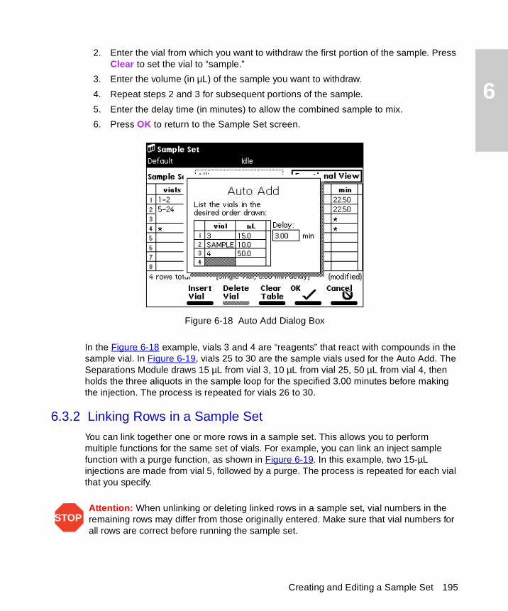
6
2. Enter the vial from which you want to withdraw the first portion of the sample. Press Clear to set the vial to “sample.”
3. Enter the volume (in µL) of the sample you want to withdraw.
4. Repeat steps 2 and 3 for subsequent portions of the sample.
5. Enter the delay time (in minutes) to allow the combined sample to mix.
6. Press OK to return to the Sample Set screen.
Figure 6-18 Auto Add Dialog Box
In the Figure 6-18 example, vials 3 and 4 are “reagents” that react with compounds in the sample vial. In Figure 6-19, vials 25 to 30 are the sample vials used for the Auto Add. The Separations Module draws 15 µL from vial 3, 10 µL from vial 25, 50 µL from vial 4, then holds the three aliquots in the sample loop for the specified 3.00 minutes before making the injection. The process is repeated for vials 26 to 30.
6.3.2 Linking Rows in a Sample Set
You can link together one or more rows in a sample set. This allows you to perform multiple functions for the same set of vials. For example, you can link an inject sample function with a purge function, as shown in Figure 6-19. In this example, two 15-µL injections are made from vial 5, followed by a purge. The process is repeated for each vial that you specify.
STOPAttention: When unlinking or deleting linked rows in a sample set, vial numbers in the remaining rows may differ from those originally entered. Make sure that vial numbers for all rows are correct before running the sample set.
Creating and Editing a Sample Set 195
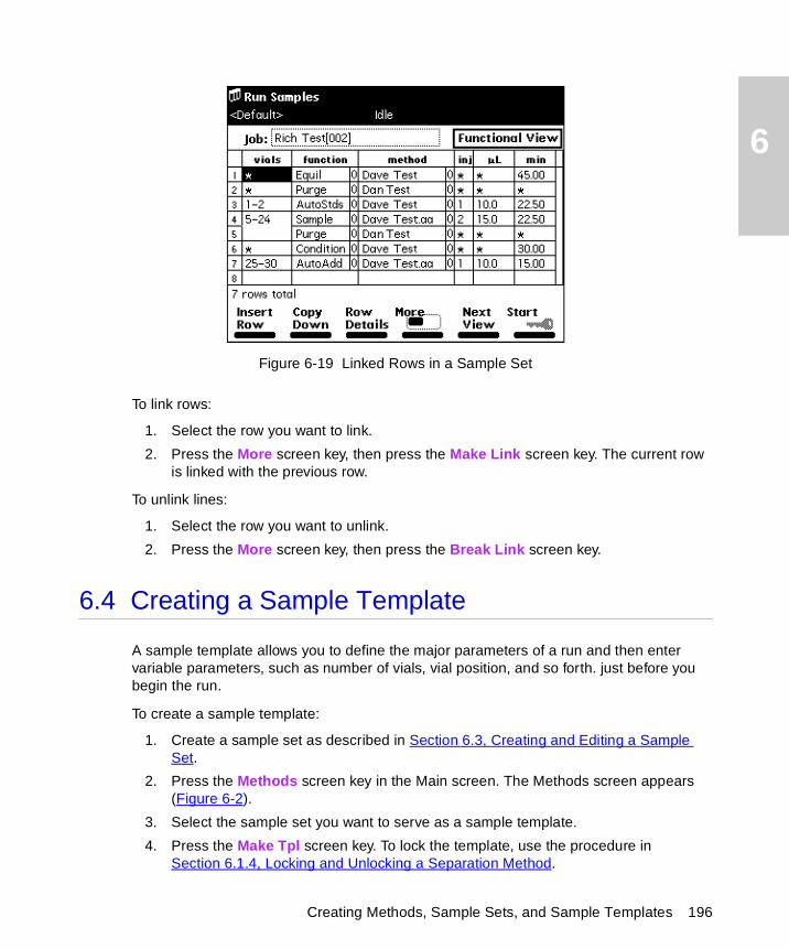
6
Figure 6-19 Linked Rows in a Sample Set
To link rows:
1. Select the row you want to link.
2. Press the More screen key, then press the Make Link screen key. The current row is linked with the previous row.
To unlink lines:
1. Select the row you want to unlink.
2. Press the More screen key, then press the Break Link screen key.
6.4 Creating a Sample Template
A sample template allows you to define the major parameters of a run and then enter variable parameters, such as number of vials, vial position, and so forth. just before you begin the run.
To create a sample template:
1. Create a sample set as described in Section 6.3, Creating and Editing a Sample Set.
2. Press the Methods screen key in the Main screen. The Methods screen appears (Figure 6-2).
3. Select the sample set you want to serve as a sample template.
4. Press the Make Tpl screen key. To lock the template, use the procedure in Section 6.1.4, Locking and Unlocking a Separation Method.
Creating Methods, Sample Sets, and Sample Templates 196
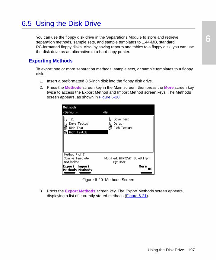
6
6.5 Using the Disk Drive
You can use the floppy disk drive in the Separations Module to store and retrieve separation methods, sample sets, and sample templates to 1.44-MB, standard PC-formatted floppy disks. Also, by saving reports and tables to a floppy disk, you can use the disk drive as an alternative to a hard-copy printer.
Exporting Methods
To export one or more separation methods, sample sets, or sample templates to a floppy disk:
1. Insert a preformatted 3.5-inch disk into the floppy disk drive.
2. Press the Methods screen key in the Main screen, then press the More screen key twice to access the Export Method and Import Method screen keys. The Methods screen appears, as shown in Figure 6-20.
Figure 6-20 Methods Screen
3. Press the Export Methods screen key. The Export Methods screen appears, displaying a list of currently stored methods (Figure 6-21).
Using the Disk Drive 197
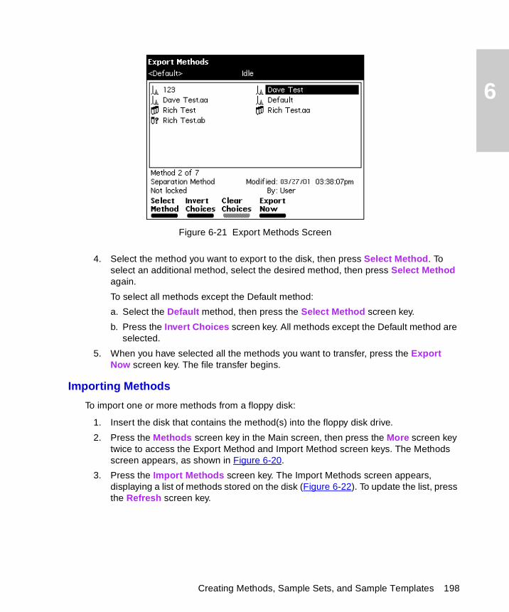
6
Figure 6-21 Export Methods Screen
4. Select the method you want to export to the disk, then press Select Method. To select an additional method, select the desired method, then press Select Method again.
To select all methods except the Default method:
a. Select the Default method, then press the Select Method screen key.
b. Press the Invert Choices screen key. All methods except the Default method are selected.
5. When you have selected all the methods you want to transfer, press the Export Now screen key. The file transfer begins.
Importing Methods
To import one or more methods from a floppy disk:
1. Insert the disk that contains the method(s) into the floppy disk drive.
2. Press the Methods screen key in the Main screen, then press the More screen key twice to access the Export Method and Import Method screen keys. The Methods screen appears, as shown in Figure 6-20.
3. Press the Import Methods screen key. The Import Methods screen appears, displaying a list of methods stored on the disk (Figure 6-22). To update the list, press the Refresh screen key.
Creating Methods, Sample Sets, and Sample Templates 198
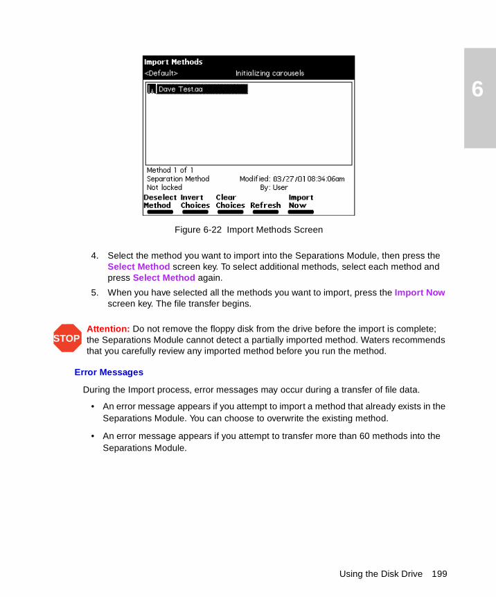
6
Figure 6-22 Import Methods Screen
4. Select the method you want to import into the Separations Module, then press the Select Method screen key. To select additional methods, select each method and press Select Method again.
5. When you have selected all the methods you want to import, press the Import Now screen key. The file transfer begins.
Error Messages
During the Import process, error messages may occur during a transfer of file data.
• An error message appears if you attempt to import a method that already exists in the Separations Module. You can choose to overwrite the existing method.
• An error message appears if you attempt to transfer more than 60 methods into the Separations Module.
STOPAttention: Do not remove the floppy disk from the drive before the import is complete; the Separations Module cannot detect a partially imported method. Waters recommends that you carefully review any imported method before you run the method.
Using the Disk Drive 199
7
Chapter 7Maintenance
This chapter describes routine maintenance procedures you can perform to ensure the Waters 2695 Separations Module consistently provides accurate and precise results.
7.1 Maintenance Considerations
Safety and Handling
When you perform maintenance procedures on your 2695 Separations Module, keep the following safety considerations in mind.
Proper Operating Procedures
To keep your 2695 Separations Module running smoothly, follow the operating procedures and guidelines described in Chapter 3, Preparing the 2695 Separations Module for Operation.
STOPAttention: To avoid damaging electrical parts, never disconnect an electrical assembly while power is applied to the 2695 Separations Module. Once power is turned off, wait 10 seconds before you disconnect an assembly.
STOPAttention: Practice proper electro-static discharge (ESD) protection to prevent damage to internal circuitry. Do not touch integrated circuit chips or other components that do not specifically require manual adjustment.
Caution: To prevent injury, always observe good laboratory practices when you handle solvents, change tubing, or operate the 2695 Separations Module. Know the physical and chemical properties of the solvents you use. Refer to the Material Safety Data Sheets for the solvents in use.
Caution: To avoid the possibility of electric shock, do not open the power supply cover. The power supply does not contain user-serviceable parts.
Maintenance Considerations 200
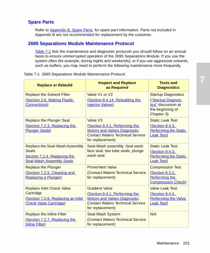
7
Spare Parts
Refer to Appendix B, Spare Parts, for spare part information. Parts not included in Appendix B are not recommended for replacement by the customer.
2695 Separations Module Maintenance Protocol
Table 7-1 lists the maintenance and diagnostic protocols you should follow on an annual basis to ensure uninterrupted operation of the 2695 Separations Module. If you use the system often (for example, during nights and weekends), or if you use aggressive solvents, such as buffers, you may need to perform the following maintenance more frequently.
Table 7-1 2695 Separations Module Maintenance Protocol
Replace or RebuildInspect and Replace
as RequiredTests and
Diagnostics
Replace the Solvent Filter(Section 2.6, Making Fluidic Connections)
Valve V1 or V2(Section 8.4.14, Rebuilding the Injector Valves)
Startup Diagnostics(“Startup Diagnos-tics” discussion at the beginning of Chapter 3)
Replace the Plunger Seal(Section 7.2.3, Replacing the Plunger Seals)
Valve V3(Section 8.4.1, Performing the Motors and Valves Diagnostic; Contact Waters Technical Service for replacement)
Static Leak Test(Section 8.4.3, Performing the Static Leak Test)
Replace the Seal-Wash Assembly SealsSection 7.2.4, Replacing the Seal-Wash Assembly Seals
Seal-Wash assembly. Seal wash face seal, two tube seals, plunge wash seal.
Static Leak Test(Section 8.4.3, Performing the Static Leak Test)
Replace the Plunger(Section 7.2.5, Cleaning and Replacing a Plunger)
Prime/Vent Valve(Contact Waters Technical Service for replacement)
Compression Test(Section 8.3.2, Performing the Compression Check)
Replace Inlet Check Valve Cartridge(Section 7.2.6, Replacing an Inlet Check Valve Cartridge)
Gradient Valve(Section 8.4.1, Performing the Motors and Valves Diagnostic; Contact Waters Technical Service for replacement)
Valve Leak Test(Section 8.4.4, Performing the Valve Leak Test)
Replace the Inline Filter(Section 7.2.7, Replacing the Inline Filter)
Seal-Wash System(Contact Waters Technical Service for replacement)
N/A
Maintenance 201
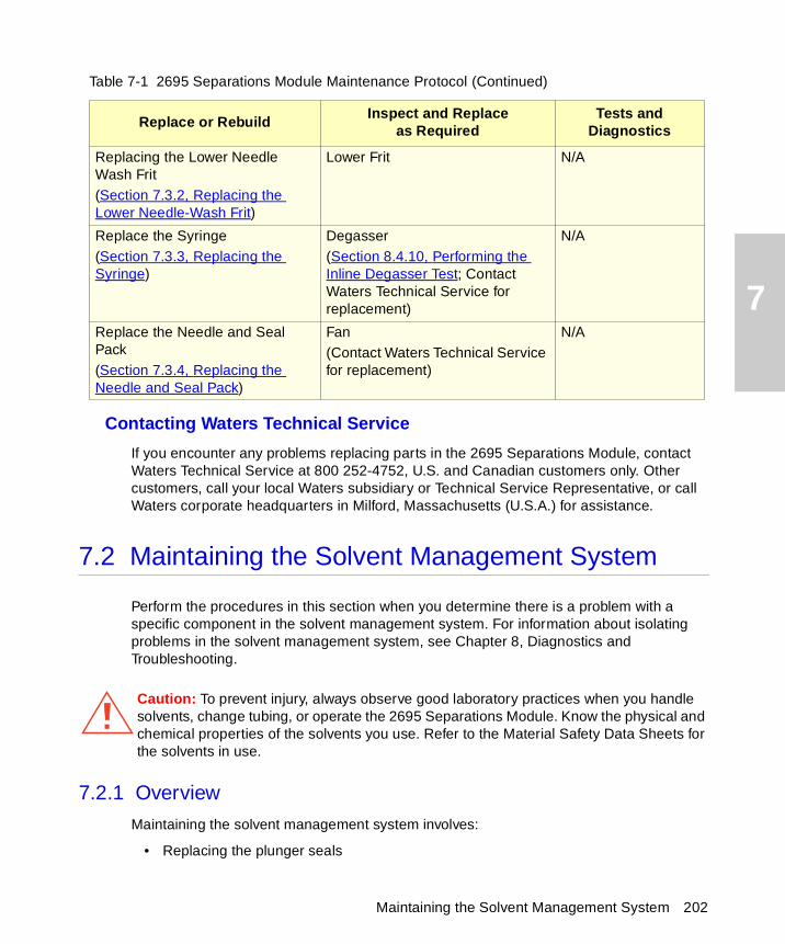
7
Contacting Waters Technical Service
If you encounter any problems replacing parts in the 2695 Separations Module, contact Waters Technical Service at 800 252-4752, U.S. and Canadian customers only. Other customers, call your local Waters subsidiary or Technical Service Representative, or call Waters corporate headquarters in Milford, Massachusetts (U.S.A.) for assistance.
7.2 Maintaining the Solvent Management System
Perform the procedures in this section when you determine there is a problem with a specific component in the solvent management system. For information about isolating problems in the solvent management system, see Chapter 8, Diagnostics and Troubleshooting.
7.2.1 Overview
Maintaining the solvent management system involves:
• Replacing the plunger seals
Replacing the Lower Needle Wash Frit(Section 7.3.2, Replacing the Lower Needle-Wash Frit)
Lower Frit N/A
Replace the Syringe(Section 7.3.3, Replacing the Syringe)
Degasser(Section 8.4.10, Performing the Inline Degasser Test; Contact Waters Technical Service for replacement)
N/A
Replace the Needle and Seal Pack(Section 7.3.4, Replacing the Needle and Seal Pack)
Fan(Contact Waters Technical Service for replacement)
N/A
Caution: To prevent injury, always observe good laboratory practices when you handle solvents, change tubing, or operate the 2695 Separations Module. Know the physical and chemical properties of the solvents you use. Refer to the Material Safety Data Sheets for the solvents in use.
Table 7-1 2695 Separations Module Maintenance Protocol (Continued)
Replace or RebuildInspect and Replace
as RequiredTests and
Diagnostics
Maintaining the Solvent Management System 202
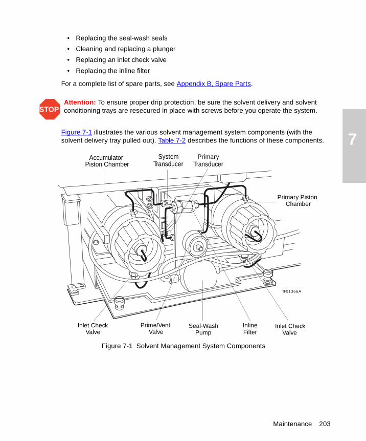
7
• Replacing the seal-wash seals
• Cleaning and replacing a plunger
• Replacing an inlet check valve
• Replacing the inline filter
For a complete list of spare parts, see Appendix B, Spare Parts.
Figure 7-1 illustrates the various solvent management system components (with the solvent delivery tray pulled out). Table 7-2 describes the functions of these components.
Figure 7-1 Solvent Management System Components
STOPAttention: To ensure proper drip protection, be sure the solvent delivery and solvent conditioning trays are resecured in place with screws before you operate the system.
TP01366A
Inline
Primary Piston
Accumulator
Prime/Vent Valve
Seal-WashPump
Inlet CheckValve
Inlet CheckValve
Chamber
SystemTransducer
PrimaryTransducerPiston Chamber
Filter
Maintenance 203
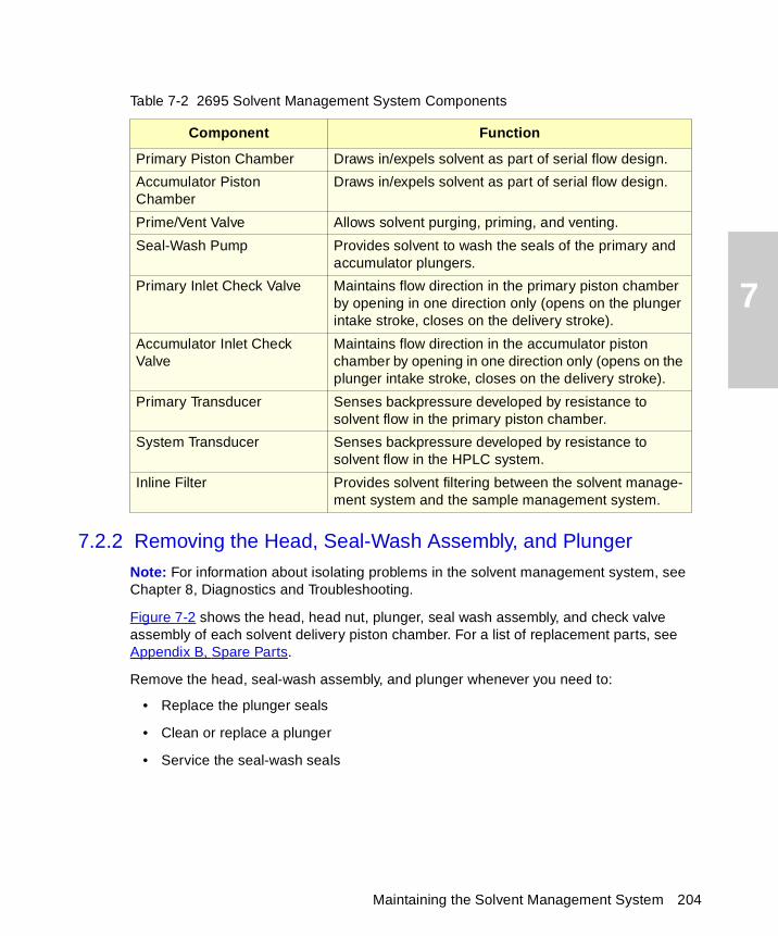
7
7.2.2 Removing the Head, Seal-Wash Assembly, and Plunger
Note: For information about isolating problems in the solvent management system, see Chapter 8, Diagnostics and Troubleshooting.
Figure 7-2 shows the head, head nut, plunger, seal wash assembly, and check valve assembly of each solvent delivery piston chamber. For a list of replacement parts, see Appendix B, Spare Parts.
Remove the head, seal-wash assembly, and plunger whenever you need to:
• Replace the plunger seals
• Clean or replace a plunger
• Service the seal-wash seals
Table 7-2 2695 Solvent Management System Components
Component Function
Primary Piston Chamber Draws in/expels solvent as part of serial flow design.
Accumulator Piston Chamber
Draws in/expels solvent as part of serial flow design.
Prime/Vent Valve Allows solvent purging, priming, and venting.
Seal-Wash Pump Provides solvent to wash the seals of the primary and accumulator plungers.
Primary Inlet Check Valve Maintains flow direction in the primary piston chamber by opening in one direction only (opens on the plunger intake stroke, closes on the delivery stroke).
Accumulator Inlet Check Valve
Maintains flow direction in the accumulator piston chamber by opening in one direction only (opens on the plunger intake stroke, closes on the delivery stroke).
Primary Transducer Senses backpressure developed by resistance to solvent flow in the primary piston chamber.
System Transducer Senses backpressure developed by resistance to solvent flow in the HPLC system.
Inline Filter Provides solvent filtering between the solvent manage-ment system and the sample management system.
Maintaining the Solvent Management System 204
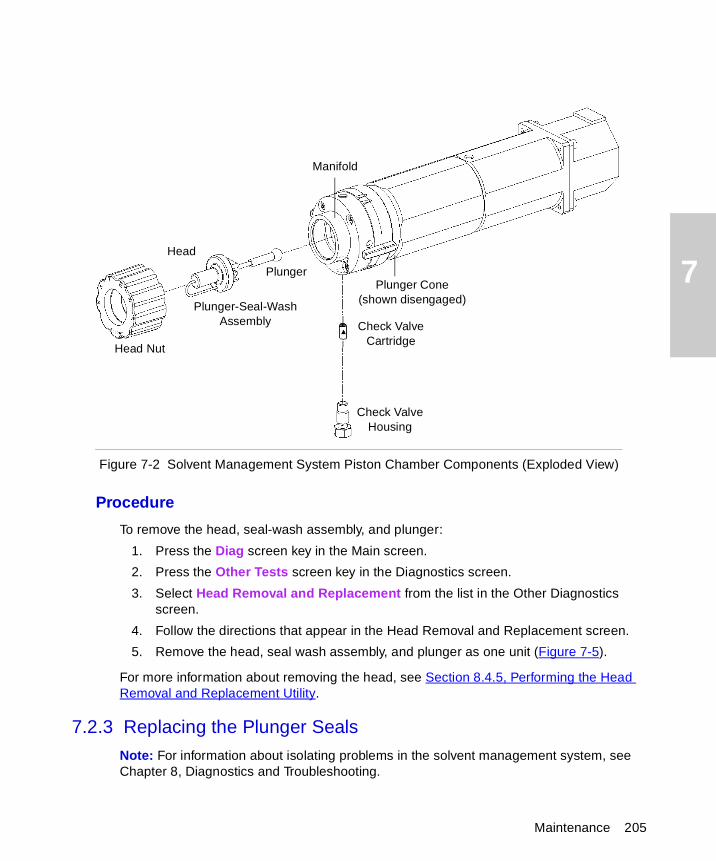
7
Figure 7-2 Solvent Management System Piston Chamber Components (Exploded View)
Procedure
To remove the head, seal-wash assembly, and plunger:
1. Press the Diag screen key in the Main screen.
2. Press the Other Tests screen key in the Diagnostics screen.
3. Select Head Removal and Replacement from the list in the Other Diagnostics screen.
4. Follow the directions that appear in the Head Removal and Replacement screen.
5. Remove the head, seal wash assembly, and plunger as one unit (Figure 7-5).
For more information about removing the head, see Section 8.4.5, Performing the Head Removal and Replacement Utility.
7.2.3 Replacing the Plunger Seals
Note: For information about isolating problems in the solvent management system, see Chapter 8, Diagnostics and Troubleshooting.
Manifold
Plunger Cone (shown disengaged)
Check Valve Cartridge
Check Valve Housing
Plunger-Seal-Wash Assembly
Head Nut
Head
Plunger
Maintenance 205
7
Note: To ensure optimum performance, replace the plunger seal in a head when you perform service. Replace the face seals after you have replaced the plunger seal two or three times (see Figure 7-3).
Note: The standard seals in the Separations Module are manufactured with Fluoroloy™-G, an ultra-high molecular weight polyethylene material. Extensive testing has indicated that these seals exhibit excellent lifetimes for the majority of solvents typically used in HPLC separations methods. If you find these seals perform unsatisfactorily for your applications, contact Waters for alternative plunger seals manufactured with graphite-filled Teflon material (part number WAT271066), or Alliance ClearSeal (part number 700001326).
This procedure involves replacing the:
• Plunger seal
• Inlet face seal
• Outlet face seal
Required Materials
• Seal insertion tool (in Startup Kit)
• Seal removal tool (part number WAT039803)
• Replacement seals
• Squeeze bottle with 100% alcohol (methanol or isopropanol)
• Clean block, such as a detector cell window (part number WAT097295)
• Syringe (in Startup Kit)
• Plastic tweezers or can of compressed air
Plunger Seal Replacement
To replace the plunger seal:
1. Remove the head as described in Section 7.2.2, Removing the Head, Seal-Wash Assembly, and Plunger.
2. Use the plastic end of the seal removal tool to remove the plunger seal from the head (Figure 7-3).
STOPAttention: To avoid damaging the sealing surfaces, use the seal removal tool. Do not use a sharp tool to remove or install seals.
Maintaining the Solvent Management System 206
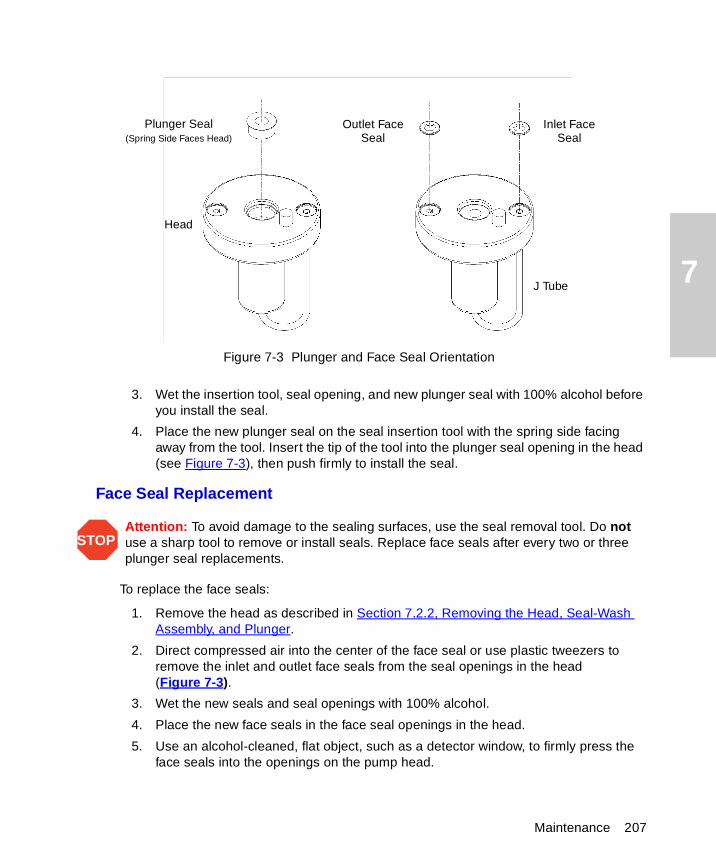
7
Figure 7-3 Plunger and Face Seal Orientation
3. Wet the insertion tool, seal opening, and new plunger seal with 100% alcohol before you install the seal.
4. Place the new plunger seal on the seal insertion tool with the spring side facing away from the tool. Insert the tip of the tool into the plunger seal opening in the head (see Figure 7-3), then push firmly to install the seal.
Face Seal Replacement
To replace the face seals:
1. Remove the head as described in Section 7.2.2, Removing the Head, Seal-Wash Assembly, and Plunger.
2. Direct compressed air into the center of the face seal or use plastic tweezers to remove the inlet and outlet face seals from the seal openings in the head (Figure 7-3).
3. Wet the new seals and seal openings with 100% alcohol.
4. Place the new face seals in the face seal openings in the head.
5. Use an alcohol-cleaned, flat object, such as a detector window, to firmly press the face seals into the openings on the pump head.
STOPAttention: To avoid damage to the sealing surfaces, use the seal removal tool. Do not use a sharp tool to remove or install seals. Replace face seals after every two or three plunger seal replacements.
Plunger Seal(Spring Side Faces Head)
Head
Outlet FaceSeal
Inlet FaceSeal
J Tube
Maintenance 207
7
6. After you replace the seals, observe the Head Removal and Replacement screen.
7. Follow the directions on the screen to reinsert the head, seal wash housing, washer, and plunger assemblies. To avoid damaging the tube seals and to properly align the seal wash tubes with the seal wash housing, refer to steps a through d below. Also, make sure that the head alignment pin is properly oriented and that the “J” tube is facing down (Figure 7-5).
a. After finger tightening the head nut onto the head, loosen (turn counterclockwise) the nut approximately 1/2-turn.
b. Inspect the ends of the seal wash tubes for damage. If necessary, trim the ends with a razor blade.
c. Reinsert the seal wash tubes into the manifold, then fully tighten the head nut.
d. Return the release ring to the run position.
8. If the Separations Module does not have solvent in the lines, perform a dry prime to draw solvent into the plunger cavity before you perform a wet prime or start delivery of solvents (see Section 3.3.4, Priming the Solvent Management System).
7.2.4 Replacing the Seal-Wash Assembly Seals
Note: For information about isolating problems in the solvent management system, see Chapter 8, Diagnostics and Troubleshooting.
This procedure involves replacing the:
• Seal-wash face seal
• Two tube seals
• Plunger wash seal
Required Materials
• Seal insertion tool (in Startup Kit)
• Seal removal tool (part number WAT039803)
• Replacement seals
• Squirt bottle with 100% alcohol (methanol or isopropanol)
• Syringe (in Startup Kit)
• Plastic tweezers
Maintaining the Solvent Management System 208
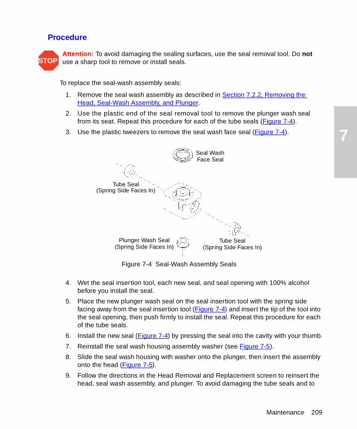
7
Procedure
To replace the seal-wash assembly seals:
1. Remove the seal wash assembly as described in Section 7.2.2, Removing the Head, Seal-Wash Assembly, and Plunger.
2. Use the plastic end of the seal removal tool to remove the plunger wash seal from its seat. Repeat this procedure for each of the tube seals (Figure 7-4).
3. Use the plastic tweezers to remove the seal wash face seal (Figure 7-4).
Figure 7-4 Seal-Wash Assembly Seals
4. Wet the seal insertion tool, each new seal, and seal opening with 100% alcohol before you install the seal.
5. Place the new plunger wash seal on the seal insertion tool with the spring side facing away from the seal insertion tool (Figure 7-4) and insert the tip of the tool into the seal opening, then push firmly to install the seal. Repeat this procedure for each of the tube seals.
6. Install the new seal (Figure 7-4) by pressing the seal into the cavity with your thumb.
7. Reinstall the seal wash housing assembly washer (see Figure 7-5).
8. Slide the seal wash housing with washer onto the plunger, then insert the assembly onto the head (Figure 7-5).
9. Follow the directions in the Head Removal and Replacement screen to reinsert the head, seal wash assembly, and plunger. To avoid damaging the tube seals and to
STOPAttention: To avoid damaging the sealing surfaces, use the seal removal tool. Do not use a sharp tool to remove or install seals.
Seal Wash
Tube Seal
Tube SealPlunger Wash Seal
(Spring Side Faces In)
(Spring Side Faces In)(Spring Side Faces In)
Face Seal
Maintenance 209
7
properly align the seal wash tubes with the seal wash housing, refer to steps a through d below. Also, make sure that the head alignment pin is properly oriented and that the “J” tube is facing down (Figure 7-5).
a. After finger tightening the head nut onto the head, loosen (turn counterclockwise) the nut approximately 1/2-turn.
b. Inspect the ends of the seal-wash tubes for damage. If necessary, trim the ends with a razor blade.
c. Reinsert the seal wash tubes into the manifold, then fully tighten the head nut.
d. Return the release ring to the run position.
10. If the Separations Module does not have solvent in the lines, perform a dry prime of the solvent management system to draw solvent into the plunger cavity before you perform a wet prime or start delivery of solvents (see Section 3.3.4, Priming the Solvent Management System).
7.2.5 Cleaning and Replacing a Plunger
Note: For information about isolating problems in the solvent management system, see Chapter 8, Diagnostics and Troubleshooting.
Required Materials
• Pumice, fine
• Cotton swab
• Water, HPLC-grade
Cleaning the Plunger
To clean the plunger:
1. Remove the head, seal-wash assembly, and plunger as described in Section 7.2.2, Removing the Head, Seal-Wash Assembly, and Plunger.
2. Inspect the plunger for damage, excessive wear, or mobile-phase residue without separating it from the pump head and seal wash assembly (Figure 7-5). If the plunger seal has mobile-phase residue:
• Separate the plunger from the head and seal-wash housing assembly.
• Clean the plunger with a fine pumice to remove any coating.
• Rinse the plunger thoroughly with water to remove all traces of abrasive, then wipe clean.
3. Reinspect the plunger. If the plunger shows excessive wear, replace the plunger.
If necessary, replace the plunger seal and face seals as described in Section 7.2.3, Replacing the Plunger Seals.
Maintaining the Solvent Management System 210
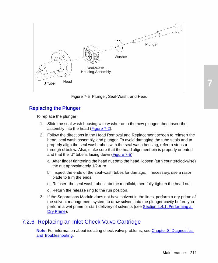
7
Figure 7-5 Plunger, Seal-Wash, and HeadReplacing the Plunger
To replace the plunger:
1. Slide the seal wash housing with washer onto the new plunger, then insert the assembly into the head (Figure 7-2).
2. Follow the directions in the Head Removal and Replacement screen to reinsert the head, seal wash assembly, and plunger. To avoid damaging the tube seals and to properly align the seal wash tubes with the seal wash housing, refer to steps a through d below. Also, make sure that the head alignment pin is properly oriented and that the “J” tube is facing down (Figure 7-5).
a. After finger tightening the head nut onto the head, loosen (turn counterclockwise) the nut approximately 1/2-turn.
b. Inspect the ends of the seal-wash tubes for damage. If necessary, use a razor blade to trim the ends.
c. Reinsert the seal wash tubes into the manifold, then fully tighten the head nut.
d. Return the release ring to the run position.
3. If the Separations Module does not have solvent in the lines, perform a dry prime of the solvent management system to draw solvent into the plunger cavity before you perform a wet prime or start delivery of solvents (see Section 4.4.1, Performing a Dry Prime).
7.2.6 Replacing an Inlet Check Valve Cartridge
Note: For information about isolating check valve problems, see Chapter 8, Diagnostics and Troubleshooting.
Head
Seal-Wash
Washer
Plunger
J Tube
Housing Assembly
Maintenance 211
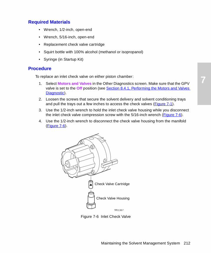
7
Required Materials
• Wrench, 1/2-inch, open-end
• Wrench, 5/16-inch, open-end
• Replacement check valve cartridge
• Squirt bottle with 100% alcohol (methanol or isopropanol)
• Syringe (in Startup Kit)
Procedure
To replace an inlet check valve on either piston chamber:
1. Select Motors and Valves in the Other Diagnostics screen. Make sure that the GPV valve is set to the Off position (see Section 8.4.1, Performing the Motors and Valves Diagnostic).
2. Loosen the screws that secure the solvent delivery and solvent conditioning trays and pull the trays out a few inches to access the check valves (Figure 7-1).
3. Use the 1/2-inch wrench to hold the inlet check valve housing while you disconnect the inlet check valve compression screw with the 5/16-inch wrench (Figure 7-6).
4. Use the 1/2-inch wrench to disconnect the check valve housing from the manifold (Figure 7-6).
Figure 7-6 Inlet Check Valve
TP01367
Check Valve Cartridge
Check Valve Housing
Maintaining the Solvent Management System 212
7
5. Tip the inlet check valve housing upside down to remove the old check valve cartridge.
6. Inspect the inlet check valve housing and clean it if necessary. Wet the housing with 100% alcohol.
7. Wet the new check valve cartridge with 100% alcohol.
8. Insert the replacement check valve cartridge into the inlet check valve housing.
9. Insert the inlet check valve housing into the piston chamber housing, then finger-tighten the check valve housing.
10. Use the 1/2-inch wrench to tighten the inlet check valve housing 1/8 of a turn.
11. Use the1/2-inch wrench to hold the check valve housing while you reinstall and tighten the compression screw into the check valve housing with the 5/16-inch wrench.
12. Select Motors and Valves from the Other Diagnostics screen. Set the GPV valve to the Solvent A position (see Section 8.4.1, Performing the Motors and Valves Diagnostic).
13. If the Separations Module does not have solvent in the lines, perform a dry prime of the solvent management system to draw solvent into the plunger cavity before you perform a wet prime or start delivery of solvents (see Section 4.4.1, Performing a Dry Prime).
7.2.7 Replacing the Inline Filter
The inline filter provides solvent filtering between the solvent management system and the sample management system. Clean and replace the inline filter element when it is the source of elevated backpressure.
Note: For information about isolating problems in the solvent management system, see Chapter 8, Diagnostics and Troubleshooting.
Required Materials
• Wrenches, 5/8-inch, open-end, two
• Wrench, 5/16-inch, open-end
• Squirt bottle with 100% alcohol (methanol or isopropanol)
• Absorbent tissue
• Replacement inline filter element
STOPAttention: Make sure that the arrow on the check valve cartridge points toward the piston chamber.
Maintenance 213
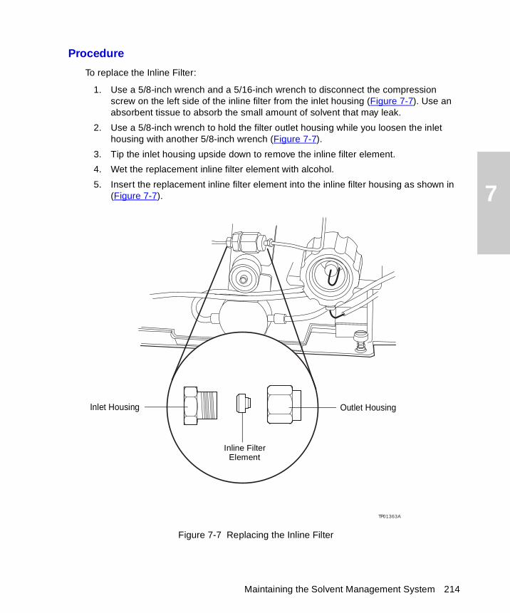
7
Procedure
To replace the Inline Filter:
1. Use a 5/8-inch wrench and a 5/16-inch wrench to disconnect the compression screw on the left side of the inline filter from the inlet housing (Figure 7-7). Use an absorbent tissue to absorb the small amount of solvent that may leak.
2. Use a 5/8-inch wrench to hold the filter outlet housing while you loosen the inlet housing with another 5/8-inch wrench (Figure 7-7).
3. Tip the inlet housing upside down to remove the inline filter element.
4. Wet the replacement inline filter element with alcohol.
5. Insert the replacement inline filter element into the inline filter housing as shown in (Figure 7-7).
Figure 7-7 Replacing the Inline Filter
TP01363A
Outlet HousingInlet Housing
Inline FilterElement
Maintaining the Solvent Management System 214
7
6. Reconnect the inline filter inlet and outlet housings.
7. Retighten the compression screw into the inlet housing.
8. Flush the solvent management system with mobile phase at 1 mL/min for 10 minutes (see Section 3.6, Powering Off the Separations Module).
9. Inspect the inline filter for leaks, and tighten the fittings as required.
7.3 Maintaining the Sample Management System
Perform the procedures in this section when you determine there is a problem with a specific component in the sample management system.
Note: For information about isolating problems in the sample management system, see Chapter 8, Diagnostics and Troubleshooting.
7.3.1 Overview
Maintaining the sample management system involves:
• Replacing the lower needle wash frit
• Replacing the syringe
• Replacing the needle and seal pack
• Cleaning the sample compartment
For a complete list of spare parts, see Appendix B, Spare Parts.
Figure 7-8 and Figure 7-9 illustrate the various assemblies and components of the sample management system. Table 7-3 describes the functions of each assembly and component.
Caution: To prevent injury, always observe good laboratory practices when you handle solvents, change tubing, or operate the 2695 Separations Module. Know the physical and chemical properties of the solvents you use. Refer to the Material Safety Data Sheets for the solvents in use.
Maintenance 215
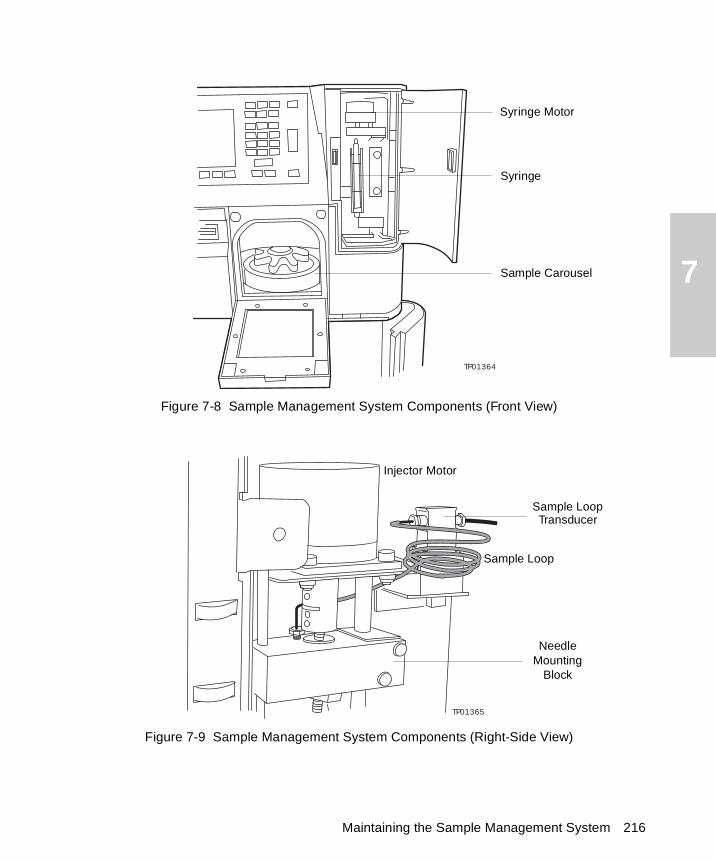
7
Figure 7-8 Sample Management System Components (Front View)
Figure 7-9 Sample Management System Components (Right-Side View)
TP01364
Sample Carousel
Syringe
Syringe Motor
TP01365
Injector Motor
Sample Loop
Sample LoopTransducer
NeedleMounting
Block
Maintaining the Sample Management System 216
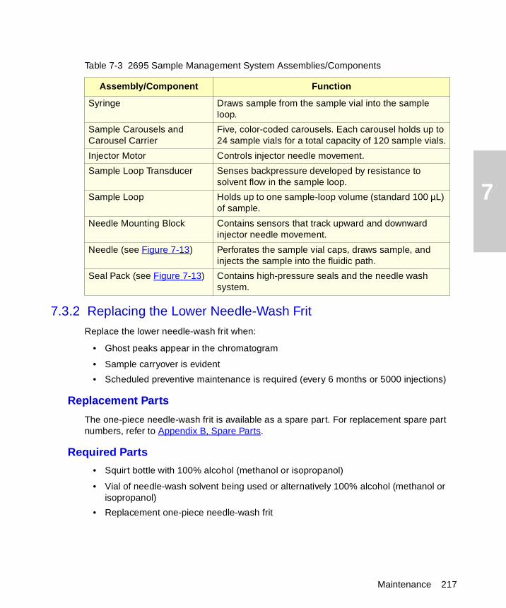
7
7.3.2 Replacing the Lower Needle-Wash Frit
Replace the lower needle-wash frit when:
• Ghost peaks appear in the chromatogram
• Sample carryover is evident
• Scheduled preventive maintenance is required (every 6 months or 5000 injections)
Replacement Parts
The one-piece needle-wash frit is available as a spare part. For replacement spare part numbers, refer to Appendix B, Spare Parts.
Required Parts
• Squirt bottle with 100% alcohol (methanol or isopropanol)
• Vial of needle-wash solvent being used or alternatively 100% alcohol (methanol or isopropanol)
• Replacement one-piece needle-wash frit
Table 7-3 2695 Sample Management System Assemblies/Components
Assembly/Component Function
Syringe Draws sample from the sample vial into the sample loop.
Sample Carousels and Carousel Carrier
Five, color-coded carousels. Each carousel holds up to 24 sample vials for a total capacity of 120 sample vials.
Injector Motor Controls injector needle movement.
Sample Loop Transducer Senses backpressure developed by resistance to solvent flow in the sample loop.
Sample Loop Holds up to one sample-loop volume (standard 100 µL) of sample.
Needle Mounting Block Contains sensors that track upward and downward injector needle movement.
Needle (see Figure 7-13) Perforates the sample vial caps, draws sample, and injects the sample into the fluidic path.
Seal Pack (see Figure 7-13) Contains high-pressure seals and the needle wash system.
Maintenance 217
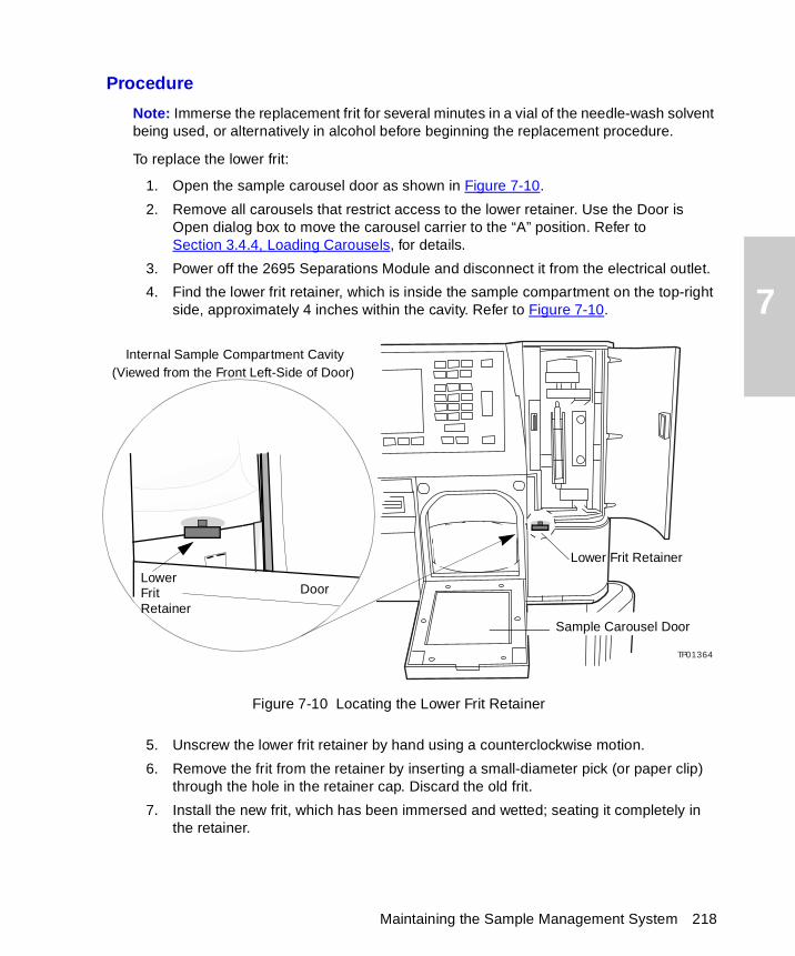
7
Procedure
Note: Immerse the replacement frit for several minutes in a vial of the needle-wash solvent being used, or alternatively in alcohol before beginning the replacement procedure.
To replace the lower frit:
1. Open the sample carousel door as shown in Figure 7-10.
2. Remove all carousels that restrict access to the lower retainer. Use the Door is Open dialog box to move the carousel carrier to the “A” position. Refer to Section 3.4.4, Loading Carousels, for details.
3. Power off the 2695 Separations Module and disconnect it from the electrical outlet.
4. Find the lower frit retainer, which is inside the sample compartment on the top-right side, approximately 4 inches within the cavity. Refer to Figure 7-10.
Figure 7-10 Locating the Lower Frit Retainer
5. Unscrew the lower frit retainer by hand using a counterclockwise motion.
6. Remove the frit from the retainer by inserting a small-diameter pick (or paper clip) through the hole in the retainer cap. Discard the old frit.
7. Install the new frit, which has been immersed and wetted; seating it completely in the retainer.
TP01364
Door
Sample Carousel Door
Internal Sample Compartment Cavity(Viewed from the Front Left-Side of Door)
LowerFritRetainer
Lower Frit Retainer
Maintaining the Sample Management System 218
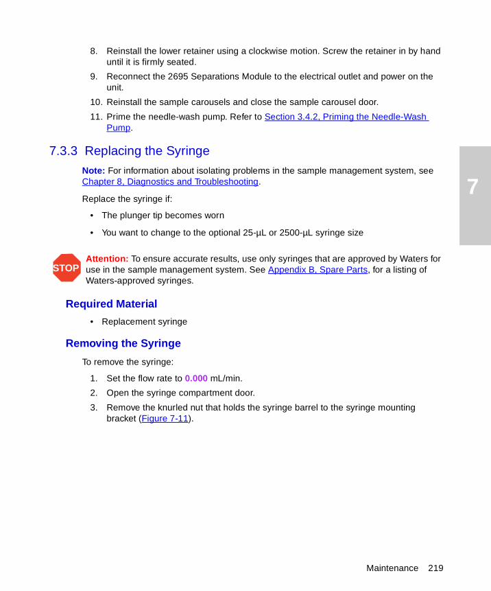
7
8. Reinstall the lower retainer using a clockwise motion. Screw the retainer in by hand until it is firmly seated.
9. Reconnect the 2695 Separations Module to the electrical outlet and power on the unit.
10. Reinstall the sample carousels and close the sample carousel door.
11. Prime the needle-wash pump. Refer to Section 3.4.2, Priming the Needle-Wash Pump.
7.3.3 Replacing the Syringe
Note: For information about isolating problems in the sample management system, see Chapter 8, Diagnostics and Troubleshooting.
Replace the syringe if:
• The plunger tip becomes worn
• You want to change to the optional 25-µL or 2500-µL syringe size
Required Material
• Replacement syringe
Removing the Syringe
To remove the syringe:
1. Set the flow rate to 0.000 mL/min.
2. Open the syringe compartment door.
3. Remove the knurled nut that holds the syringe barrel to the syringe mounting bracket (Figure 7-11).
STOPAttention: To ensure accurate results, use only syringes that are approved by Waters for use in the sample management system. See Appendix B, Spare Parts, for a listing of Waters-approved syringes.
Maintenance 219
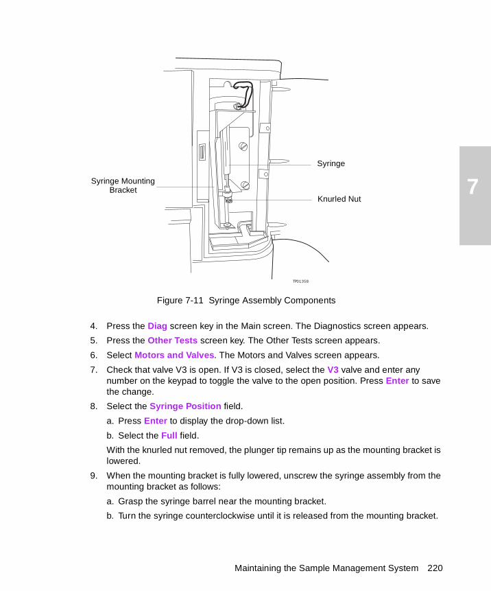
7
Figure 7-11 Syringe Assembly Components
4. Press the Diag screen key in the Main screen. The Diagnostics screen appears.
5. Press the Other Tests screen key. The Other Tests screen appears.
6. Select Motors and Valves. The Motors and Valves screen appears.
7. Check that valve V3 is open. If V3 is closed, select the V3 valve and enter any number on the keypad to toggle the valve to the open position. Press Enter to save the change.
8. Select the Syringe Position field.
a. Press Enter to display the drop-down list.
b. Select the Full field.
With the knurled nut removed, the plunger tip remains up as the mounting bracket is lowered.
9. When the mounting bracket is fully lowered, unscrew the syringe assembly from the mounting bracket as follows:
a. Grasp the syringe barrel near the mounting bracket.
b. Turn the syringe counterclockwise until it is released from the mounting bracket.
TP01358
TP01358
Knurled Nut
Syringe MountingBracket
Syringe
Maintaining the Sample Management System 220
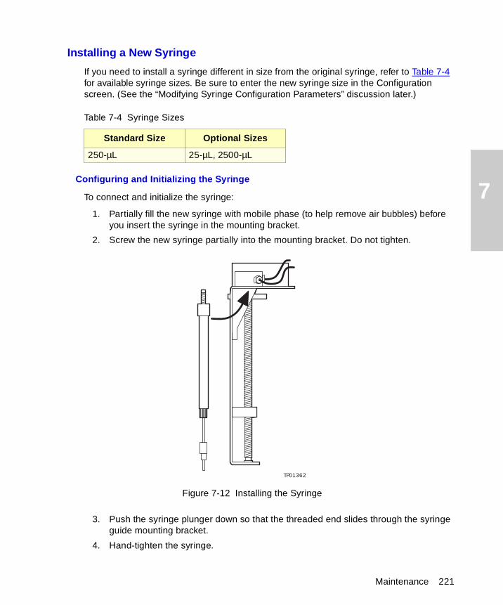
7
Installing a New Syringe
If you need to install a syringe different in size from the original syringe, refer to Table 7-4 for available syringe sizes. Be sure to enter the new syringe size in the Configuration screen. (See the “Modifying Syringe Configuration Parameters” discussion later.)
Configuring and Initializing the Syringe
To connect and initialize the syringe:
1. Partially fill the new syringe with mobile phase (to help remove air bubbles) before you insert the syringe in the mounting bracket.
2. Screw the new syringe partially into the mounting bracket. Do not tighten.
Figure 7-12 Installing the Syringe
3. Push the syringe plunger down so that the threaded end slides through the syringe guide mounting bracket.
4. Hand-tighten the syringe.
Table 7-4 Syringe Sizes
Standard Size Optional Sizes
250-µL 25-µL, 2500-µL
TP01362
Maintenance 221
7
5. Press Other Tests in the Diagnostic screen. The Other Tests screen appears.
6. Select the Syringe Position field, then press Enter to display the drop-down list.
7. Select Empty, then press Enter. The mounting bracket moves upward to allow you to install the knurled nut.
8. Press the Exit key to exit the Other Tests screen.
9. Install and finger-tighten the knurled nut.
Modifying Syringe Configuration Parameters
If the replacement syringe differs in size from the original syringe, you need to configure the 2695 Separations Module for a new syringe size according to the following procedure (see Figure 3-5).
1. Press the Configure screen key in the Main screen to display the Configuration screen.
2. Select the Syringe Size field. In the drop-down menu, select the appropriate syringe size, then press Enter.
3. Press the Exit key to return to the Main screen.
Note: For more information about changing the syringe size, see Section 3.2, Configuring the Separations Module.
Purging the Sample Management System
Once you have installed a new syringe, purge the sample management system with at least six sample loop volumes to remove any bubbles that may exist in the system.
To purge the sample management system:
1. Press the Menu/Status key to display the Control screen.
2. Select <direct> in the Method field.
3. Set the pump to deliver 1 mL/min of degassed or sparged 100% methanol.
4. Select the purge cycle parameters:
a. Press the Direct Function screen key.
b. Select Purge Injector, then press Enter.
c. Enter 6 in the Number of Sample Loop Volumes field, then press Enter.
d. Select the Compression Test check box to perform a compression test (to check for air bubbles in the syringe).
5. Press OK to start the purge cycle.
Note: For more information about purging the sample management system, see Section 3.4.1, Purging the Sample Management System.
Maintaining the Sample Management System 222
7
7.3.4 Replacing the Needle and Seal Pack
Note: Use the optional PerformancePLUS nickel/cobalt needle (part number 700001326) to reduce loss of proteins that adhere to the standard stainless steel needle.
Replace the needle and seal pack when:
• The needle is bent.
• The tip of the needle is damaged.
• Contaminant peaks appear in the chromatogram that cannot be corrected by changing the wash solvent in the needle wash system.
Note: For information about isolating problems in the sample management system, see Chapter 8, Diagnostics and Troubleshooting.
The procedure for replacing the needle involves:
• Removing the injector
• Removing the seal pack
• Removing and replacing the needle
• Installing the injector
• Installing the new seal pack
• Adjusting the seal pack
Required Materials
• Wrench, T-10 TORX
• Wrench, T-20 TORX
• Wrenches, 5/16-inch, two
• Squirt bottle with 100% alcohol (methanol or isopropanol)
• Screwdriver, long, flat-blade
Required Kits
You need one of the following kits to replace the seal pack:
• Seal Pack Assembly and Needle Kit – Includes an assembled seal pack, replacement needle, and instructions
• Seal Pack Seal Replacement Kit – Includes seal pack seals, frits, replacement needle, and instructions
Removing the Injector
To remove the injector:
1. Power off the 2695 Separations Module.
Maintenance 223
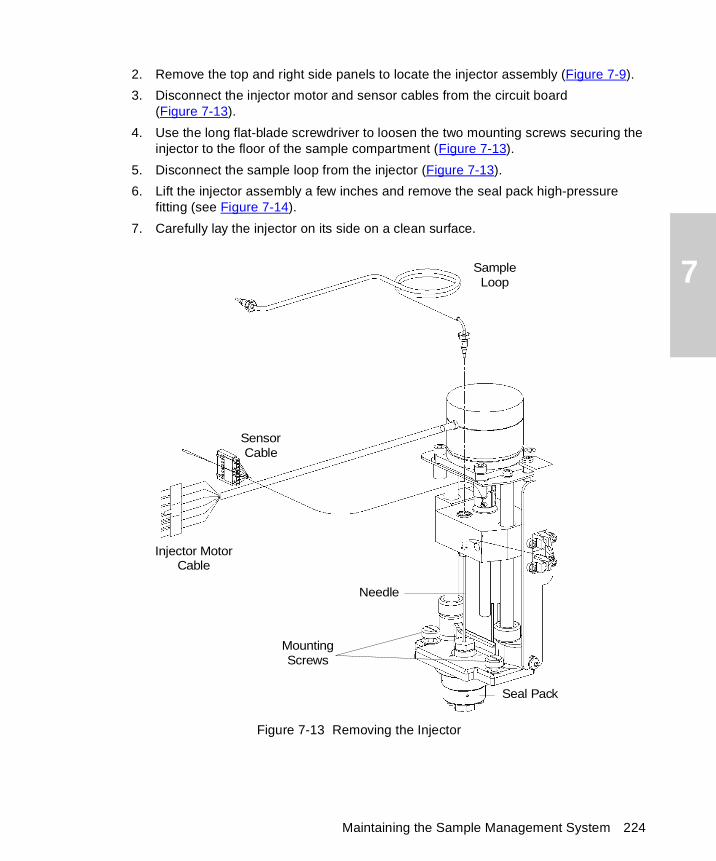
7
2. Remove the top and right side panels to locate the injector assembly (Figure 7-9).
3. Disconnect the injector motor and sensor cables from the circuit board (Figure 7-13).
4. Use the long flat-blade screwdriver to loosen the two mounting screws securing the injector to the floor of the sample compartment (Figure 7-13).
5. Disconnect the sample loop from the injector (Figure 7-13).
6. Lift the injector assembly a few inches and remove the seal pack high-pressure fitting (see Figure 7-14).
7. Carefully lay the injector on its side on a clean surface.
Figure 7-13 Removing the Injector
SampleLoop
SensorCable
Injector MotorCable
Seal Pack
MountingScrews
Needle
Maintaining the Sample Management System 224
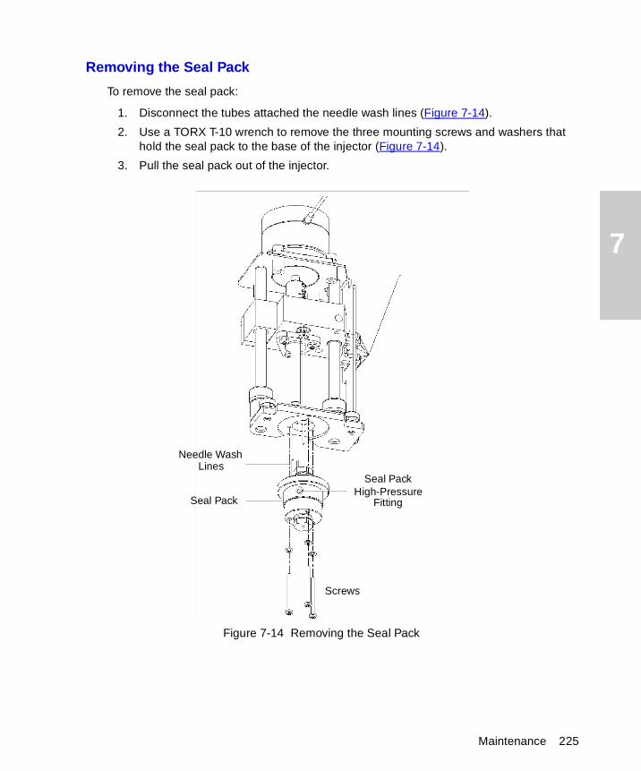
7
Removing the Seal Pack
To remove the seal pack:
1. Disconnect the tubes attached the needle wash lines (Figure 7-14).
2. Use a TORX T-10 wrench to remove the three mounting screws and washers that hold the seal pack to the base of the injector (Figure 7-14).
3. Pull the seal pack out of the injector.
Figure 7-14 Removing the Seal Pack
Needle WashLines
Screws
Seal Pack
Seal PackHigh-Pressure
Fitting
Maintenance 225
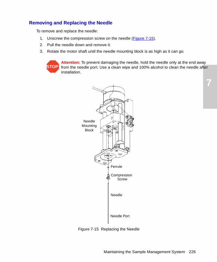
7
ay after
Removing and Replacing the Needle
To remove and replace the needle:
1. Unscrew the compression screw on the needle (Figure 7-15).
2. Pull the needle down and remove it.
3. Rotate the motor shaft until the needle mounting block is as high as it can go.
Figure 7-15 Replacing the Needle
STOPAttention: To prevent damaging the needle, hold the needle only at the end awfrom the needle port. Use a clean wipe and 100% alcohol to clean the needle installation.
Ferrule
Compression Screw
Needle
Needle Port
NeedleMounting
Block
Maintaining the Sample Management System 226
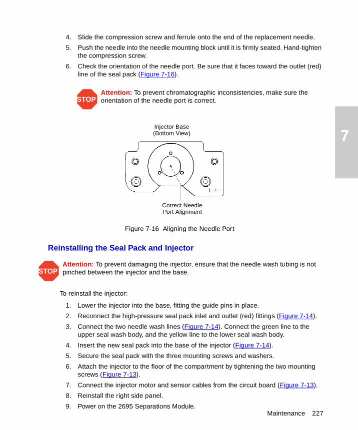
7
Maintenance 227
4. Slide the compression screw and ferrule onto the end of the replacement needle.
5. Push the needle into the needle mounting block until it is firmly seated. Hand-tighten the compression screw.
6. Check the orientation of the needle port. Be sure that it faces toward the outlet (red) line of the seal pack (Figure 7-16).
Figure 7-16 Aligning the Needle Port
Reinstalling the Seal Pack and Injector
To reinstall the injector:
1. Lower the injector into the base, fitting the guide pins in place.
2. Reconnect the high-pressure seal pack inlet and outlet (red) fittings (Figure 7-14).
3. Connect the two needle wash lines (Figure 7-14). Connect the green line to the upper seal wash body, and the yellow line to the lower seal wash body.
4. Insert the new seal pack into the base of the injector (Figure 7-14).
5. Secure the seal pack with the three mounting screws and washers.
6. Attach the injector to the floor of the compartment by tightening the two mounting screws (Figure 7-13).
7. Connect the injector motor and sensor cables from the circuit board (Figure 7-13).
8. Reinstall the right side panel.
9. Power on the 2695 Separations Module.
STOPAttention: To prevent chromatographic inconsistencies, make sure theorientation of the needle port is correct.
STOPAttention: To prevent damaging the injector, ensure that the needle wash tubing is not pinched between the injector and the base.
Injector Base(Bottom View)
Correct NeedlePort Alignment
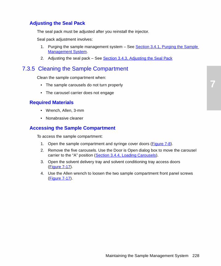
7
Adjusting the Seal Pack
The seal pack must be adjusted after you reinstall the injector.
Seal pack adjustment involves:
1. Purging the sample management system – See Section 3.4.1, Purging the Sample Management System.
2. Adjusting the seal pack – See Section 3.4.3, Adjusting the Seal Pack
7.3.5 Cleaning the Sample Compartment
Clean the sample compartment when:
• The sample carousels do not turn properly
• The carousel carrier does not engage
Required Materials
• Wrench, Allen, 3-mm
• Nonabrasive cleaner
Accessing the Sample Compartment
To access the sample compartment:
1. Open the sample compartment and syringe cover doors (Figure 7-8).
2. Remove the five carousels. Use the Door is Open dialog box to move the carousel carrier to the “A” position (Section 3.4.4, Loading Carousels).
3. Open the solvent delivery tray and solvent conditioning tray access doors (Figure 7-17).
4. Use the Allen wrench to loosen the two sample compartment front panel screws (Figure 7-17).
Maintaining the Sample Management System 228
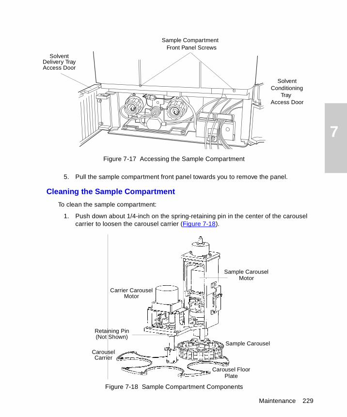
7
Figure 7-17 Accessing the Sample Compartment
5. Pull the sample compartment front panel towards you to remove the panel.
Cleaning the Sample Compartment
To clean the sample compartment:
1. Push down about 1/4-inch on the spring-retaining pin in the center of the carousel carrier to loosen the carousel carrier (Figure 7-18).
Figure 7-18 Sample Compartment Components
SolventDelivery TrayAccess Door
SolventConditioning
TrayAccess Door
Sample CompartmentFront Panel Screws
Sample Carousel
CarouselCarrier
Retaining Pin(Not Shown)
Carousel FloorPlate
Sample CarouselMotor
Carrier CarouselMotor
Maintenance 229
7
2. Slide the carousel carrier toward the front of the unit, then remove the carousel carrier (Figure 7-18).
3. Remove the carousel floor plate and clean with a non-abrasive cleaner (Figure 7-18).
4. Reinstall the carousel floor plate.
5. Push down about 1/4-inch on the spring-retaining pin in the center of the carousel carrier to reinstall the carousel carrier.
6. Reinstall the sample compartment front panel with the two sample compartment front panel screws.
7.4 Updating the Software Version Using the Floppy Disk Drive
You can update the software version on your 2695 Separations Module by copying the software from a Waters 2695 Firmware Update Disk to the system ROM chips using the diskette drive on the front panel of the unit.
Note: If you have not used the floppy disk drive for a long period of time, Waters recommends that you exercise the drive mechanics before performing the software update procedure. Exercise the drive by exporting a separation method or sample set to a formatted floppy disk, then importing the same method or sample set (see Section 6.5, Using the Disk Drive).
Procedure
To update the software version:
1. Insert the Waters 2695 Firmware Update Disk into the floppy disk drive on the front panel of the 2695 Separations Module.
2. Power on the 2695 Separations Module.
3. When the startup diagnostics are complete, you are prompted to proceed with the update.
4. Select Yes, then follow additional prompts as required. The update procedure takes about 15 minutes. Do not power off the unit during the update procedure.
STOPAttention: To prevent a mandatory service call to replace ROM chips, make sure that you do not power off the 2695 Separations Module during the software update procedure.
Updating the Software Version Using the Floppy Disk Drive 230

8
Chapter 8Diagnostics and Troubleshooting
This chapter describes how to troubleshoot the 2695 Separations Module with the help of user-initiated diagnostics and recommended troubleshooting procedures. This chapter covers:
• Safety and handling
• Using the error log
• Performing diagnostics
• Troubleshooting
Note: For information about startup diagnostics, see the “Startup Diagnostics” discussion in Chapter 3.
Proper Operating Procedures
To keep your Waters 2695 Separations Module running optimally, follow the operating procedures and guidelines described in Chapter 3, Preparing the 2695 Separations Module for Operation.
Spare Parts
Refer to Appendix B, Spare Parts, for spare parts information. Parts not included in Appendix B are not recommended for replacement by the customer.
Contacting Waters Technical Service
If you encounter any problems performing diagnostics or troubleshooting the 2695 Separations Module, contact Waters Technical Service at 800 252-4752, U.S. and Canadian customers only. Other customers, call your local Waters subsidiary or Technical Service Representative, or contact Waters corporate headquarters in Milford, Massachusetts (U.S.A.) for assistance.
8.1 Safety and Handling
When you troubleshoot the 2695 Separations Module, keep the following safety considerations in mind:
Safety and Handling 231
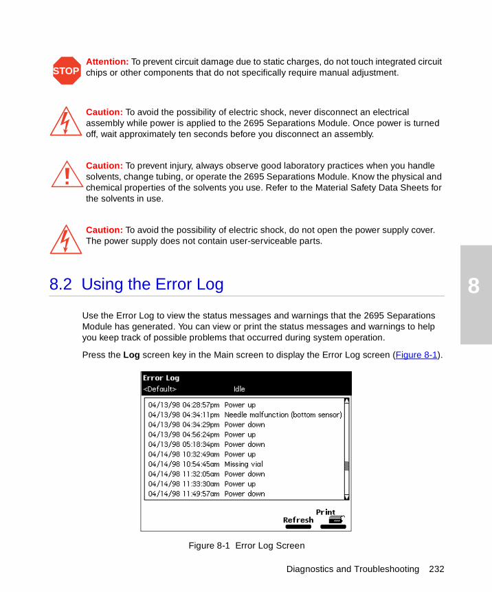
8
8.2 Using the Error LogUse the Error Log to view the status messages and warnings that the 2695 Separations Module has generated. You can view or print the status messages and warnings to help you keep track of possible problems that occurred during system operation.
Press the Log screen key in the Main screen to display the Error Log screen (Figure 8-1).
Figure 8-1 Error Log Screen
STOPAttention: To prevent circuit damage due to static charges, do not touch integrated circuit chips or other components that do not specifically require manual adjustment.
Caution: To avoid the possibility of electric shock, never disconnect an electrical assembly while power is applied to the 2695 Separations Module. Once power is turned off, wait approximately ten seconds before you disconnect an assembly.
Caution: To prevent injury, always observe good laboratory practices when you handle solvents, change tubing, or operate the 2695 Separations Module. Know the physical and chemical properties of the solvents you use. Refer to the Material Safety Data Sheets for the solvents in use.
Caution: To avoid the possibility of electric shock, do not open the power supply cover. The power supply does not contain user-serviceable parts.
Diagnostics and Troubleshooting 232
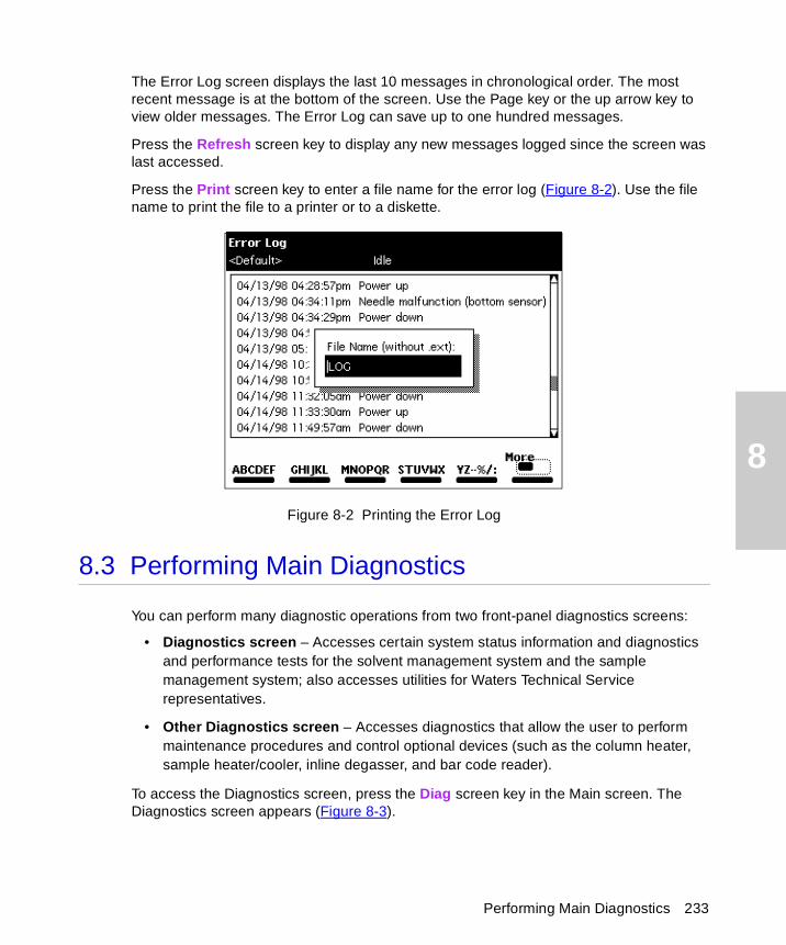
8
The Error Log screen displays the last 10 messages in chronological order. The most recent message is at the bottom of the screen. Use the Page key or the up arrow key to view older messages. The Error Log can save up to one hundred messages.
Press the Refresh screen key to display any new messages logged since the screen was last accessed.
Press the Print screen key to enter a file name for the error log (Figure 8-2). Use the file name to print the file to a printer or to a diskette.
Figure 8-2 Printing the Error Log
8.3 Performing Main Diagnostics
You can perform many diagnostic operations from two front-panel diagnostics screens:
• Diagnostics screen – Accesses certain system status information and diagnostics and performance tests for the solvent management system and the sample management system; also accesses utilities for Waters Technical Service representatives.
• Other Diagnostics screen – Accesses diagnostics that allow the user to perform maintenance procedures and control optional devices (such as the column heater, sample heater/cooler, inline degasser, and bar code reader).
To access the Diagnostics screen, press the Diag screen key in the Main screen. The Diagnostics screen appears (Figure 8-3).
Performing Main Diagnostics 233
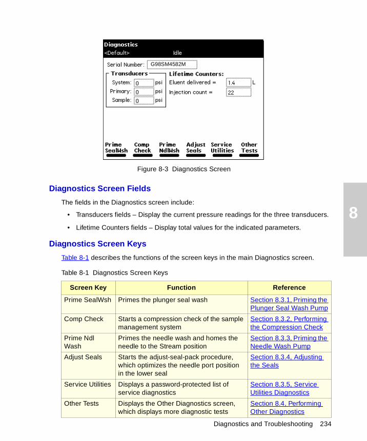
8
Diagnostics and Troubleshooting 234
Figure 8-3 Diagnostics Screen
Diagnostics Screen Fields
The fields in the Diagnostics screen include:
• Transducers fields – Display the current pressure readings for the three transducers.
• Lifetime Counters fields – Display total values for the indicated parameters.
Diagnostics Screen Keys
Table 8-1 describes the functions of the screen keys in the main Diagnostics screen.
Table 8-1 Diagnostics Screen Keys
Screen Key Function Reference
Prime SealWsh Primes the plunger seal wash Section 8.3.1, Priming the Plunger Seal Wash Pump
Comp Check Starts a compression check of the sample management system
Section 8.3.2, Performing the Compression Check
Prime Ndl Wash
Primes the needle wash and homes the needle to the Stream position
Section 8.3.3, Priming the Needle Wash Pump
Adjust Seals Starts the adjust-seal-pack procedure, which optimizes the needle port position in the lower seal
Section 8.3.4, Adjusting the Seals
Service Utilities Displays a password-protected list of service diagnostics
Section 8.3.5, Service Utilities Diagnostics
Other Tests Displays the Other Diagnostics screen, which displays more diagnostic tests
Section 8.4, Performing Other Diagnostics
G98SM4582M
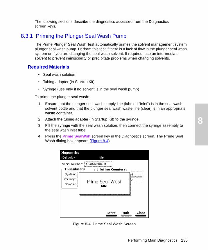
8
The following sections describe the diagnostics accessed from the Diagnostics screen keys.
8.3.1 Priming the Plunger Seal Wash Pump
The Prime Plunger Seal Wash Test automatically primes the solvent management system plunger seal wash pump. Perform this test if there is a lack of flow in the plunger seal wash system or if you are changing the seal wash solvent. If required, use an intermediate solvent to prevent immiscibility or precipitate problems when changing solvents.
Required Materials
• Seal wash solution
• Tubing adapter (in Startup Kit)
• Syringe (use only if no solvent is in the seal wash pump)
To prime the plunger seal wash:
1. Ensure that the plunger seal wash supply line (labeled “Inlet”) is in the seal wash solvent bottle and that the plunger seal wash waste line (clear) is in an appropriate waste container.
2. Attach the tubing adapter (in Startup Kit) to the syringe.
3. Fill the syringe with the seal wash solution, then connect the syringe assembly to the seal wash inlet tube.
4. Press the Prime SealWsh screen key in the Diagnostics screen. The Prime Seal Wash dialog box appears (Figure 8-4).
Figure 8-4 Prime Seal Wash Screen
G98SM4582M
Performing Main Diagnostics 235
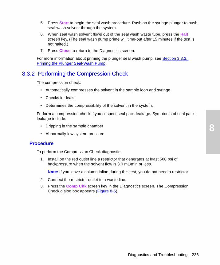
8
5. Press Start to begin the seal wash procedure. Push on the syringe plunger to push seal wash solvent through the system.
6. When seal wash solvent flows out of the seal wash waste tube, press the Halt screen key. (The seal wash pump prime will time-out after 15 minutes if the test is not halted.)
7. Press Close to return to the Diagnostics screen.
For more information about priming the plunger seal wash pump, see Section 3.3.3, Priming the Plunger Seal-Wash Pump.
8.3.2 Performing the Compression Check
The compression check:
• Automatically compresses the solvent in the sample loop and syringe
• Checks for leaks
• Determines the compressibility of the solvent in the system.
Perform a compression check if you suspect seal pack leakage. Symptoms of seal pack leakage include:
• Dripping in the sample chamber
• Abnormally low system pressure
Procedure
To perform the Compression Check diagnostic:
1. Install on the red outlet line a restrictor that generates at least 500 psi of backpressure when the solvent flow is 3.0 mL/min or less.
Note: If you leave a column inline during this test, you do not need a restrictor.
2. Connect the restrictor outlet to a waste line.
3. Press the Comp Chk screen key in the Diagnostics screen. The Compression Check dialog box appears (Figure 8-5).
Diagnostics and Troubleshooting 236
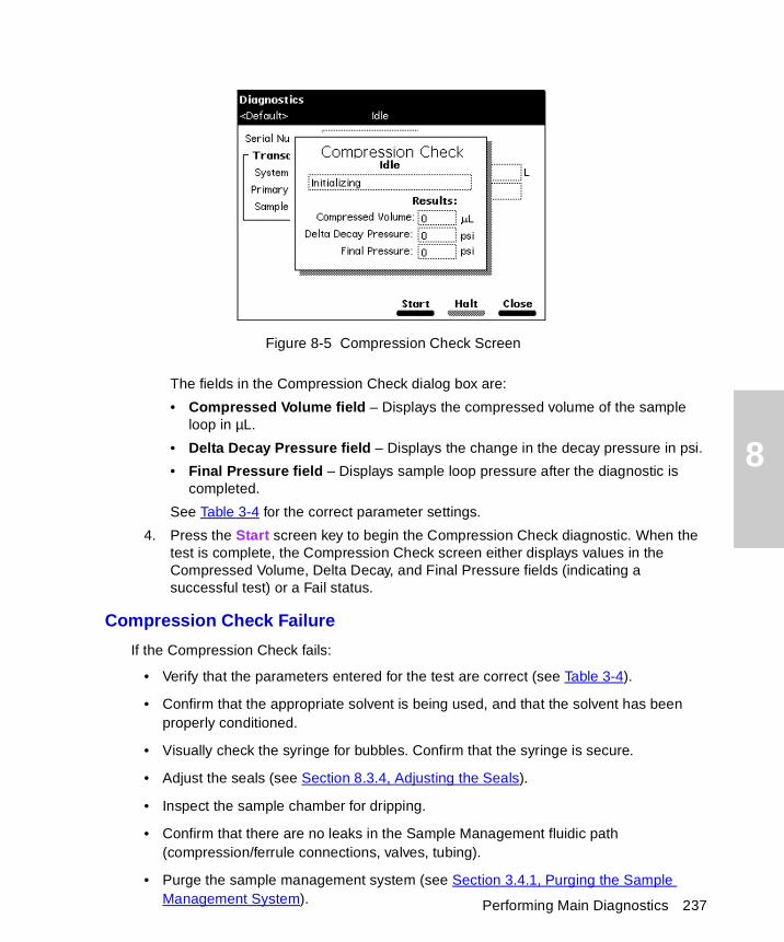
8
Performing Main Diagnostics 237
Figure 8-5 Compression Check Screen
The fields in the Compression Check dialog box are:
• Compressed Volume field – Displays the compressed volume of the sample loop in µL.
• Delta Decay Pressure field – Displays the change in the decay pressure in psi.
• Final Pressure field – Displays sample loop pressure after the diagnostic is completed.
See Table 3-4 for the correct parameter settings.
4. Press the Start screen key to begin the Compression Check diagnostic. When the test is complete, the Compression Check screen either displays values in the Compressed Volume, Delta Decay, and Final Pressure fields (indicating a successful test) or a Fail status.
Compression Check Failure
If the Compression Check fails:
• Verify that the parameters entered for the test are correct (see Table 3-4).
• Confirm that the appropriate solvent is being used, and that the solvent has been properly conditioned.
• Visually check the syringe for bubbles. Confirm that the syringe is secure.
• Adjust the seals (see Section 8.3.4, Adjusting the Seals).
• Inspect the sample chamber for dripping.
• Confirm that there are no leaks in the Sample Management fluidic path (compression/ferrule connections, valves, tubing).
• Purge the sample management system (see Section 3.4.1, Purging the Sample Management System).
8
8.3.3 Priming the Needle Wash Pump
The Prime Needle Wash Pump procedure automatically primes the needle wash system and homes the needle into the stream position. Perform this procedure if:
• There is a lack of flow in the needle wash system
• You are changing the seal wash solvent
• There is a needle sensor malfunction
To prime the needle wash:
1. Ensure that the needle wash supply line (green) is in the solvent bottle and that the waste line (yellow) is in an appropriate waste container.
2. Press the Prime NdlWash screen key in the Diagnostics screen. The Prime Needle Wash dialog box appears (Figure 8-6).
Figure 8-6 Prime Needle Wash Dialog Box
3. Press the Start screen key to begin the needle wash. If the solvent does not flow out of the waste line within 30 seconds, press Start again. If the solvent still does not flow out of the waste line:
• Check the sample chamber for dripping from the injector
• Check if fluid is being withdrawn from the needle wash reservoir
8.3.4 Adjusting the Seals
The Adjust Seals procedure automatically adjusts and optimizes the vertical needle port position in the seal of the autoinjector.
Diagnostics and Troubleshooting 238
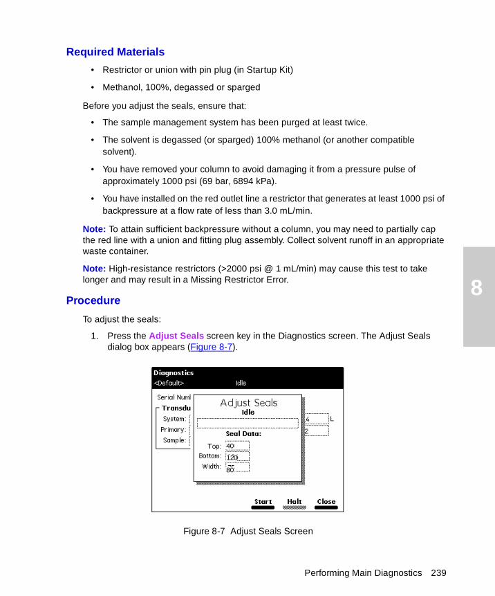
8
Required Materials
• Restrictor or union with pin plug (in Startup Kit)
• Methanol, 100%, degassed or sparged
Before you adjust the seals, ensure that:
• The sample management system has been purged at least twice.
• The solvent is degassed (or sparged) 100% methanol (or another compatible solvent).
• You have removed your column to avoid damaging it from a pressure pulse of approximately 1000 psi (69 bar, 6894 kPa).
• You have installed on the red outlet line a restrictor that generates at least 1000 psi of backpressure at a flow rate of less than 3.0 mL/min.
Note: To attain sufficient backpressure without a column, you may need to partially cap the red line with a union and fitting plug assembly. Collect solvent runoff in an appropriate waste container.
Note: High-resistance restrictors (>2000 psi @ 1 mL/min) may cause this test to take longer and may result in a Missing Restrictor Error.
Procedure
To adjust the seals:
1. Press the Adjust Seals screen key in the Diagnostics screen. The Adjust Seals dialog box appears (Figure 8-7).
Figure 8-7 Adjust Seals Screen
40
120
80
Performing Main Diagnostics 239
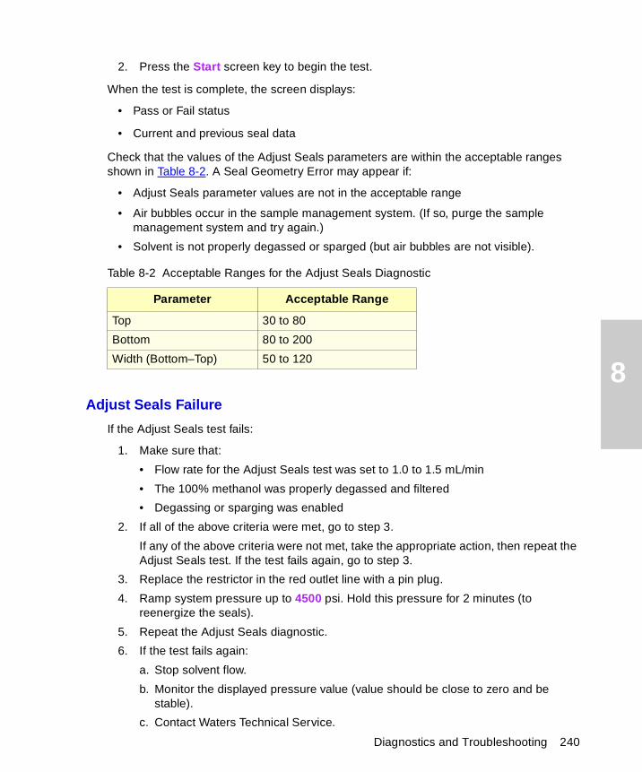
8
Diagnostics and Troubleshooting 240
2. Press the Start screen key to begin the test.
When the test is complete, the screen displays:
• Pass or Fail status
• Current and previous seal data
Check that the values of the Adjust Seals parameters are within the acceptable ranges shown in Table 8-2. A Seal Geometry Error may appear if:
• Adjust Seals parameter values are not in the acceptable range
• Air bubbles occur in the sample management system. (If so, purge the sample management system and try again.)
• Solvent is not properly degassed or sparged (but air bubbles are not visible).
Adjust Seals Failure
If the Adjust Seals test fails:
1. Make sure that:
• Flow rate for the Adjust Seals test was set to 1.0 to 1.5 mL/min
• The 100% methanol was properly degassed and filtered
• Degassing or sparging was enabled
2. If all of the above criteria were met, go to step 3.
If any of the above criteria were not met, take the appropriate action, then repeat the Adjust Seals test. If the test fails again, go to step 3.
3. Replace the restrictor in the red outlet line with a pin plug.
4. Ramp system pressure up to 4500 psi. Hold this pressure for 2 minutes (to reenergize the seals).
5. Repeat the Adjust Seals diagnostic.
6. If the test fails again:
a. Stop solvent flow.
b. Monitor the displayed pressure value (value should be close to zero and be stable).
c. Contact Waters Technical Service.
Table 8-2 Acceptable Ranges for the Adjust Seals Diagnostic
Parameter Acceptable Range
Top 30 to 80
Bottom 80 to 200
Width (Bottom–Top) 50 to 120
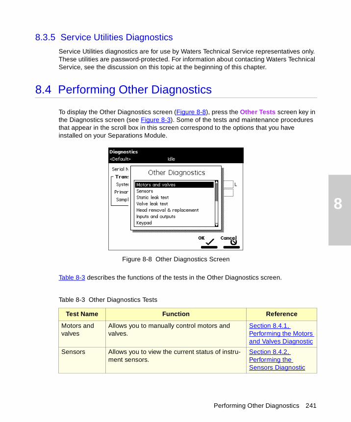
8
8.3.5 Service Utilities Diagnostics
Service Utilities diagnostics are for use by Waters Technical Service representatives only. These utilities are password-protected. For information about contacting Waters Technical Service, see the discussion on this topic at the beginning of this chapter.
8.4 Performing Other Diagnostics
To display the Other Diagnostics screen (Figure 8-8), press the Other Tests screen key in the Diagnostics screen (see Figure 8-3). Some of the tests and maintenance procedures that appear in the scroll box in this screen correspond to the options that you have installed on your Separations Module.
Figure 8-8 Other Diagnostics Screen
Table 8-3 describes the functions of the tests in the Other Diagnostics screen.
Table 8-3 Other Diagnostics Tests
Test Name Function Reference
Motors and valves
Allows you to manually control motors and valves.
Section 8.4.1, Performing the Motors and Valves Diagnostic
Sensors Allows you to view the current status of instru-ment sensors.
Section 8.4.2, Performing the Sensors Diagnostic
Performing Other Diagnostics 241
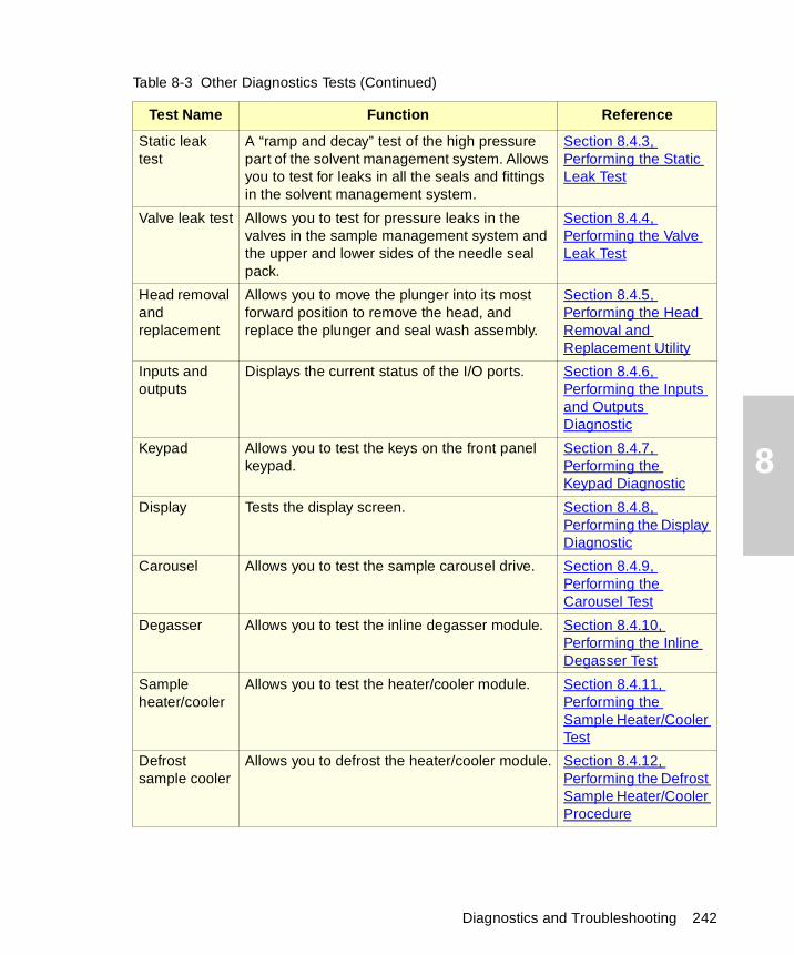
8
Static leak test
A “ramp and decay” test of the high pressure part of the solvent management system. Allows you to test for leaks in all the seals and fittings in the solvent management system.
Section 8.4.3, Performing the Static Leak Test
Valve leak test Allows you to test for pressure leaks in the valves in the sample management system and the upper and lower sides of the needle seal pack.
Section 8.4.4, Performing the Valve Leak Test
Head removal and replacement
Allows you to move the plunger into its most forward position to remove the head, and replace the plunger and seal wash assembly.
Section 8.4.5, Performing the Head Removal and Replacement Utility
Inputs and outputs
Displays the current status of the I/O ports. Section 8.4.6, Performing the Inputs and Outputs Diagnostic
Keypad Allows you to test the keys on the front panel keypad.
Section 8.4.7, Performing the Keypad Diagnostic
Display Tests the display screen. Section 8.4.8, Performing the Display Diagnostic
Carousel Allows you to test the sample carousel drive. Section 8.4.9, Performing the Carousel Test
Degasser Allows you to test the inline degasser module. Section 8.4.10, Performing the Inline Degasser Test
Sample heater/cooler
Allows you to test the heater/cooler module. Section 8.4.11, Performing the Sample Heater/Cooler Test
Defrost sample cooler
Allows you to defrost the heater/cooler module. Section 8.4.12, Performing the Defrost Sample Heater/Cooler Procedure
Table 8-3 Other Diagnostics Tests (Continued)
Test Name Function Reference
Diagnostics and Troubleshooting 242
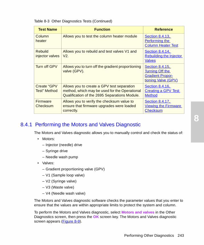
8
Performing Other Diagnostics 243
8.4.1 Performing the Motors and Valves Diagnostic
The Motors and Valves diagnostic allows you to manually control and check the status of:
• Motors:
– Injector (needle) drive
– Syringe drive
– Needle wash pump
• Valves:
– Gradient proportioning valve (GPV)
– V1 (Sample loop valve)
– V2 (Syringe valve)
– V3 (Waste valve)
– V4 (Needle wash valve)
The Motors and Valves diagnostic software checks the parameter values that you enter to ensure that the values are within appropriate limits to protect the system and column.
To perform the Motors and Valves diagnostic, select Motors and valves in the Other Diagnostics screen, then press the OK screen key. The Motors and Valves diagnostic screen appears (Figure 8-9).
Column heater
Allows you to test the column heater module Section 8.4.13, Performing the Column Heater Test
Rebuild injector valves
Allows you to rebuild and test valves V1 and V2.
Section 8.4.14, Rebuilding the Injector Valves
Turn off GPV Allows you to turn off the gradient proportioning valve (GPV).
Section 8.4.15, Turning Off the Gradient Propor-tioning Valve (GPV)
Create “GPV Test” Method
Allows you to create a GPV test separation method, which may be used for the Operational Qualification of the 2695 Separations Module.
Section 8.4.16, Creating a GPV Test Method
Firmware Checksum
Allows you to verify the checksum value to ensure that firmware upgrades were loaded correctly.
Section 8.4.17, Viewing the Firmware Checksum
Table 8-3 Other Diagnostics Tests (Continued)
Test Name Function Reference
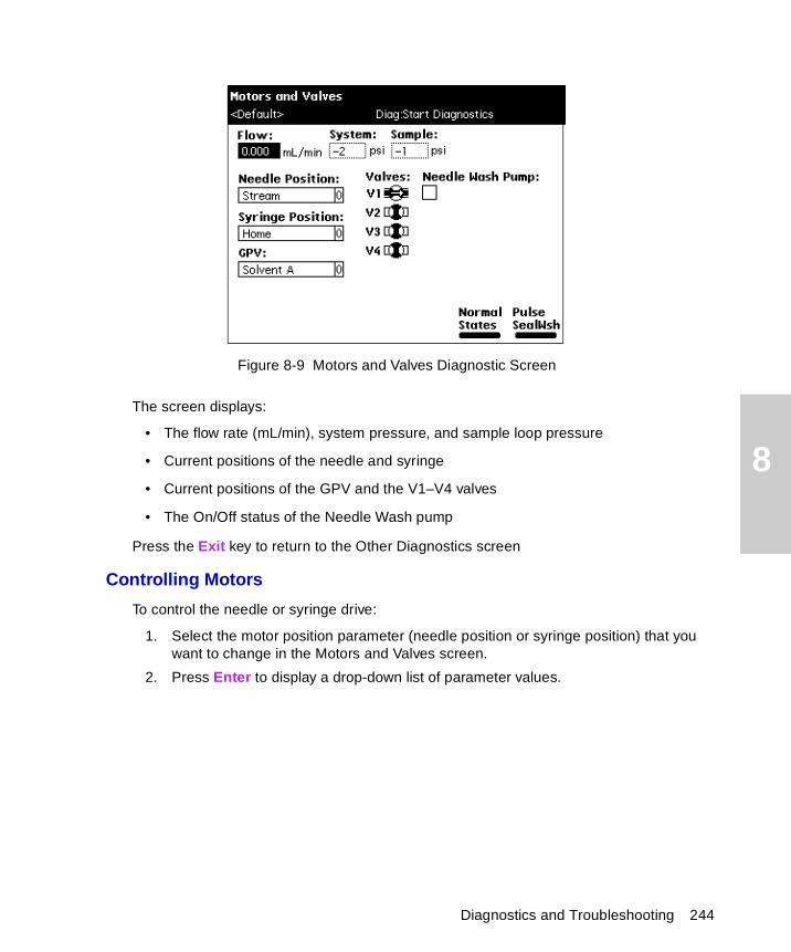
8
Figure 8-9 Motors and Valves Diagnostic Screen
The screen displays:
• The flow rate (mL/min), system pressure, and sample loop pressure
• Current positions of the needle and syringe
• Current positions of the GPV and the V1–V4 valves
• The On/Off status of the Needle Wash pump
Press the Exit key to return to the Other Diagnostics screen
Controlling Motors
To control the needle or syringe drive:
1. Select the motor position parameter (needle position or syringe position) that you want to change in the Motors and Valves screen.
2. Press Enter to display a drop-down list of parameter values.
Diagnostics and Troubleshooting 244
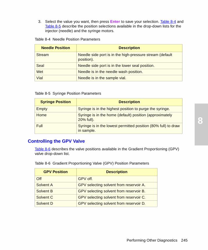
8
3. Select the value you want, then press Enter to save your selection. Table 8-4 and Table 8-5 describe the position selections available in the drop-down lists for the injector (needle) and the syringe motors.
Controlling the GPV Valve
Table 8-6 describes the valve positions available in the Gradient Proportioning (GPV) valve drop-down list.
Table 8-4 Needle Position Parameters
Needle Position Description
Stream Needle side port is in the high-pressure stream (default position).
Seal Needle side port is in the lower seal position.
Wet Needle is in the needle wash position.
Vial Needle is in the sample vial.
Table 8-5 Syringe Position Parameters
Syringe Position Description
Empty Syringe is in the highest position to purge the syringe.
Home Syringe is in the home (default) position (approximately 20% full).
Full Syringe is in the lowest permitted position (80% full) to draw in sample.
Table 8-6 Gradient Proportioning Valve (GPV) Position Parameters
GPV Position Description
Off GPV off.
Solvent A GPV selecting solvent from reservoir A.
Solvent B GPV selecting solvent from reservoir B.
Solvent C GPV selecting solvent from reservoir C.
Solvent D GPV selecting solvent from reservoir D.
Performing Other Diagnostics 245
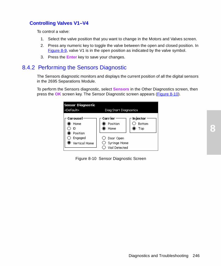
8
Controlling Valves V1–V4
To control a valve:
1. Select the valve position that you want to change in the Motors and Valves screen.
2. Press any numeric key to toggle the valve between the open and closed position. In Figure 8-9, valve V1 is in the open position as indicated by the valve symbol.
3. Press the Enter key to save your changes.
8.4.2 Performing the Sensors Diagnostic
The Sensors diagnostic monitors and displays the current position of all the digital sensors in the 2695 Separations Module.
To perform the Sensors diagnostic, select Sensors in the Other Diagnostics screen, then press the OK screen key. The Sensor Diagnostic screen appears (Figure 8-10).
Figure 8-10 Sensor Diagnostic Screen
Diagnostics and Troubleshooting 246
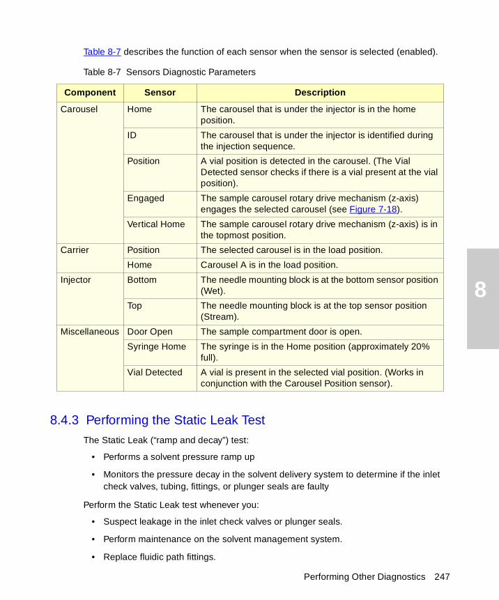
8
Table 8-7 describes the function of each sensor when the sensor is selected (enabled).
8.4.3 Performing the Static Leak Test
The Static Leak (“ramp and decay”) test:
• Performs a solvent pressure ramp up
• Monitors the pressure decay in the solvent delivery system to determine if the inlet check valves, tubing, fittings, or plunger seals are faulty
Perform the Static Leak test whenever you:
• Suspect leakage in the inlet check valves or plunger seals.
• Perform maintenance on the solvent management system.
• Replace fluidic path fittings.
Table 8-7 Sensors Diagnostic Parameters
Component Sensor Description
Carousel Home The carousel that is under the injector is in the home position.
ID The carousel that is under the injector is identified during the injection sequence.
Position A vial position is detected in the carousel. (The Vial Detected sensor checks if there is a vial present at the vial position).
Engaged The sample carousel rotary drive mechanism (z-axis) engages the selected carousel (see Figure 7-18).
Vertical Home The sample carousel rotary drive mechanism (z-axis) is in the topmost position.
Carrier Position The selected carousel is in the load position.
Home Carousel A is in the load position.
Injector Bottom The needle mounting block is at the bottom sensor position (Wet).
Top The needle mounting block is at the top sensor position (Stream).
Miscellaneous Door Open The sample compartment door is open.
Syringe Home The syringe is in the Home position (approximately 20% full).
Vial Detected A vial is present in the selected vial position. (Works in conjunction with the Carousel Position sensor).
Performing Other Diagnostics 247
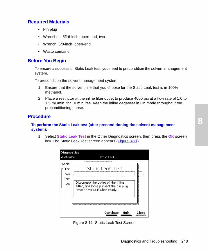
8
Required Materials
• Pin plug
• Wrenches, 5/16-inch, open-end, two
• Wrench, 5/8-inch, open-end
• Waste container
Before You Begin
To ensure a successful Static Leak test, you need to precondition the solvent management system.
To precondition the solvent management system:
1. Ensure that the solvent line that you choose for the Static Leak test is in 100% methanol.
2. Place a restrictor at the inline filter outlet to produce 4000 psi at a flow rate of 1.0 to 1.5 mL/min. for 10 minutes. Keep the inline degasser in On mode throughout the preconditioning phase.
Procedure
To perform the Static Leak test (after preconditioning the solvent management system):
1. Select Static Leak Test in the Other Diagnostics screen, then press the OK screen key. The Static Leak Test screen appears (Figure 8-11).
Figure 8-11 Static Leak Test Screen
Diagnostics and Troubleshooting 248
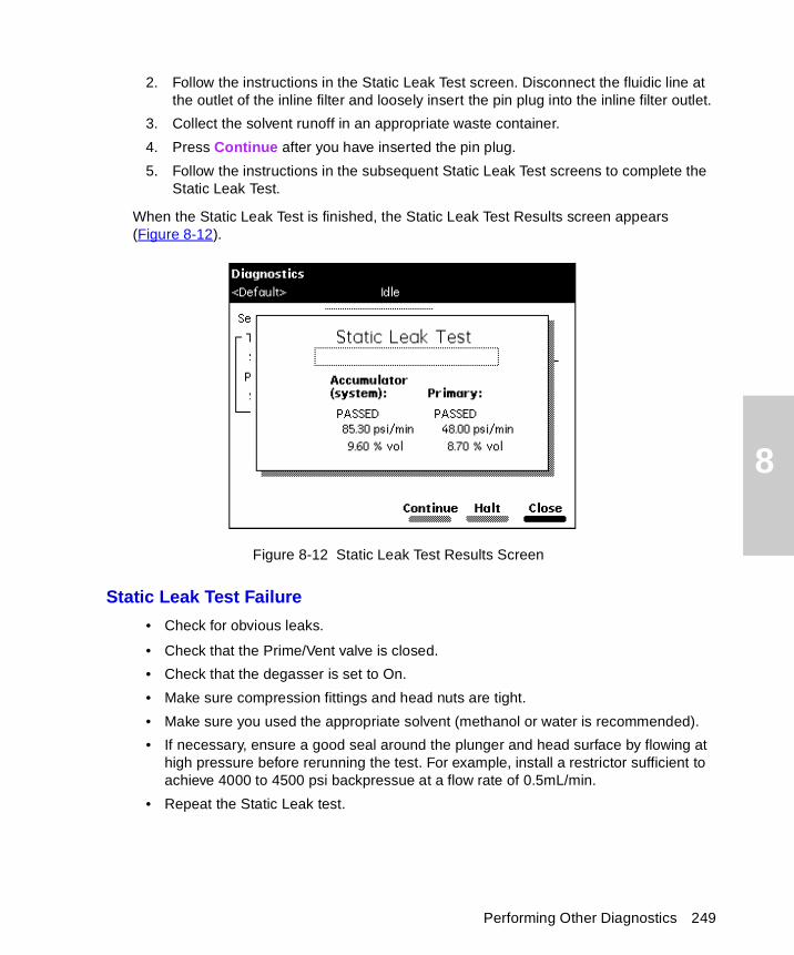
8
2. Follow the instructions in the Static Leak Test screen. Disconnect the fluidic line at the outlet of the inline filter and loosely insert the pin plug into the inline filter outlet.
3. Collect the solvent runoff in an appropriate waste container.
4. Press Continue after you have inserted the pin plug.
5. Follow the instructions in the subsequent Static Leak Test screens to complete the Static Leak Test.
When the Static Leak Test is finished, the Static Leak Test Results screen appears (Figure 8-12).
Figure 8-12 Static Leak Test Results Screen
Static Leak Test Failure
• Check for obvious leaks.
• Check that the Prime/Vent valve is closed.
• Check that the degasser is set to On.
• Make sure compression fittings and head nuts are tight.
• Make sure you used the appropriate solvent (methanol or water is recommended).
• If necessary, ensure a good seal around the plunger and head surface by flowing at high pressure before rerunning the test. For example, install a restrictor sufficient to achieve 4000 to 4500 psi backpressue at a flow rate of 0.5mL/min.
• Repeat the Static Leak test.
Performing Other Diagnostics 249
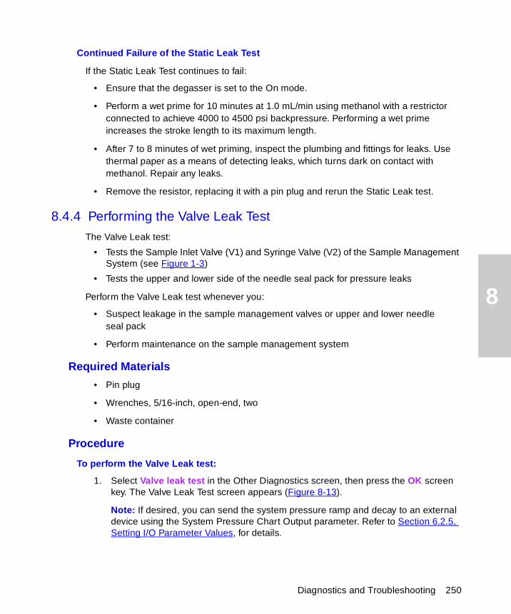
8
Continued Failure of the Static Leak Test
If the Static Leak Test continues to fail:
• Ensure that the degasser is set to the On mode.
• Perform a wet prime for 10 minutes at 1.0 mL/min using methanol with a restrictor connected to achieve 4000 to 4500 psi backpressure. Performing a wet prime increases the stroke length to its maximum length.
• After 7 to 8 minutes of wet priming, inspect the plumbing and fittings for leaks. Use thermal paper as a means of detecting leaks, which turns dark on contact with methanol. Repair any leaks.
• Remove the resistor, replacing it with a pin plug and rerun the Static Leak test.
8.4.4 Performing the Valve Leak Test
The Valve Leak test:
• Tests the Sample Inlet Valve (V1) and Syringe Valve (V2) of the Sample Management System (see Figure 1-3)
• Tests the upper and lower side of the needle seal pack for pressure leaks
Perform the Valve Leak test whenever you:
• Suspect leakage in the sample management valves or upper and lower needle seal pack
• Perform maintenance on the sample management system
Required Materials
• Pin plug
• Wrenches, 5/16-inch, open-end, two
• Waste container
Procedure
To perform the Valve Leak test:
1. Select Valve leak test in the Other Diagnostics screen, then press the OK screen key. The Valve Leak Test screen appears (Figure 8-13).
Note: If desired, you can send the system pressure ramp and decay to an external device using the System Pressure Chart Output parameter. Refer to Section 6.2.5, Setting I/O Parameter Values, for details.
Diagnostics and Troubleshooting 250
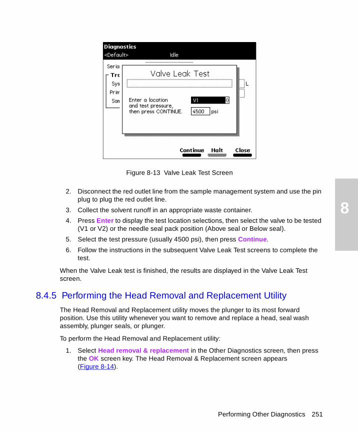
8
Figure 8-13 Valve Leak Test Screen
2. Disconnect the red outlet line from the sample management system and use the pin plug to plug the red outlet line.
3. Collect the solvent runoff in an appropriate waste container.
4. Press Enter to display the test location selections, then select the valve to be tested (V1 or V2) or the needle seal pack position (Above seal or Below seal).
5. Select the test pressure (usually 4500 psi), then press Continue.
6. Follow the instructions in the subsequent Valve Leak Test screens to complete the test.
When the Valve Leak test is finished, the results are displayed in the Valve Leak Test screen.
8.4.5 Performing the Head Removal and Replacement Utility
The Head Removal and Replacement utility moves the plunger to its most forward position. Use this utility whenever you want to remove and replace a head, seal wash assembly, plunger seals, or plunger.
To perform the Head Removal and Replacement utility:
1. Select Head removal & replacement in the Other Diagnostics screen, then press the OK screen key. The Head Removal & Replacement screen appears (Figure 8-14).
Performing Other Diagnostics 251
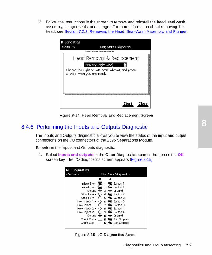
8
Diagnostics and Troubleshooting 252
2. Follow the instructions in the screen to remove and reinstall the head, seal wash assembly, plunger seals, and plunger. For more information about removing the head, see Section 7.2.2, Removing the Head, Seal-Wash Assembly, and Plunger.
Figure 8-14 Head Removal and Replacement Screen
8.4.6 Performing the Inputs and Outputs Diagnostic
The Inputs and Outputs diagnostic allows you to view the status of the input and output connections on the I/O connectors of the 2695 Separations Module.
To perform the Inputs and Outputs diagnostic:
1. Select Inputs and outputs in the Other Diagnostics screen, then press the OK screen key. The I/O diagnostics screen appears (Figure 8-15).
Figure 8-15 I/O Diagnostics Screen
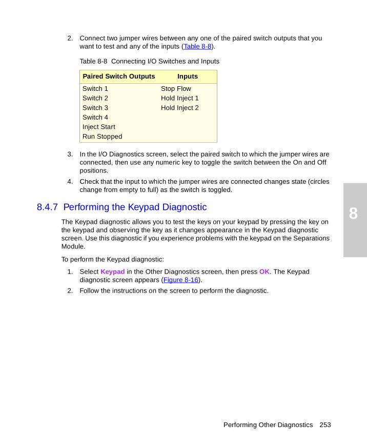
8
2. Connect two jumper wires between any one of the paired switch outputs that you want to test and any of the inputs (Table 8-8).
3. In the I/O Diagnostics screen, select the paired switch to which the jumper wires are connected, then use any numeric key to toggle the switch between the On and Off positions.
4. Check that the input to which the jumper wires are connected changes state (circles change from empty to full) as the switch is toggled.
8.4.7 Performing the Keypad Diagnostic
The Keypad diagnostic allows you to test the keys on your keypad by pressing the key on the keypad and observing the key as it changes appearance in the Keypad diagnostic screen. Use this diagnostic if you experience problems with the keypad on the Separations Module.
To perform the Keypad diagnostic:
1. Select Keypad in the Other Diagnostics screen, then press OK. The Keypad diagnostic screen appears (Figure 8-16).
2. Follow the instructions on the screen to perform the diagnostic.
Table 8-8 Connecting I/O Switches and Inputs
Paired Switch Outputs Inputs
Switch 1Switch 2Switch 3Switch 4Inject StartRun Stopped
Stop FlowHold Inject 1Hold Inject 2
Performing Other Diagnostics 253
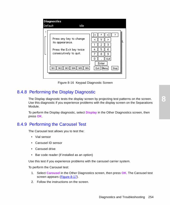
8
Figure 8-16 Keypad Diagnostic Screen
8.4.8 Performing the Display Diagnostic
The Display diagnostic tests the display screen by projecting test patterns on the screen. Use this diagnostic if you experience problems with the display screen on the Separations Module.
To perform the Display diagnostic, select Display in the Other Diagnostics screen, then press OK.
8.4.9 Performing the Carousel Test
The Carousel test allows you to test the:
• Vial sensor
• Carousel ID sensor
• Carousel drive
• Bar code reader (if installed as an option)
Use this test if you experience problems with the carousel carrier system.
To perform the Carousel test:
1. Select Carousel in the Other Diagnostics screen, then press OK. The Carousel test screen appears (Figure 8-17).
2. Follow the instructions on the screen.
Diagnostics and Troubleshooting 254
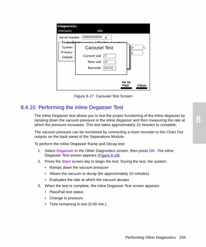
8
Figure 8-17 Carousel Test Screen
8.4.10 Performing the Inline Degasser Test
The Inline Degasser test allows you to test the proper functioning of the inline degasser by ramping down the vacuum pressure in the inline degasser and then measuring the rate at which the pressure increases. This test takes approximately 15 minutes to complete.
The vacuum pressure can be monitored by connecting a chart recorder to the Chart Out outputs on the back panel of the Separations Module.
To perform the Inline Degasser Ramp and Decay test:
1. Select Degasser in the Other Diagnostics screen, then press OK. The inline Degasser Test screen appears (Figure 8-18).
2. Press the Start screen key to begin the test. During the test, the system:
• Ramps down the vacuum pressure
• Allows the vacuum to decay (for approximately 10 minutes)
• Evaluates the rate at which the vacuum decays
3. When the test is complete, the inline Degasser Test screen appears:
• Pass/Fail test status
• Change in pressure
• Time remaining in test (0.00 min.)
G98SM4582M
Carousel Test
Current vial:
New vial:
Barcode:
9
10
001131
Performing Other Diagnostics 255
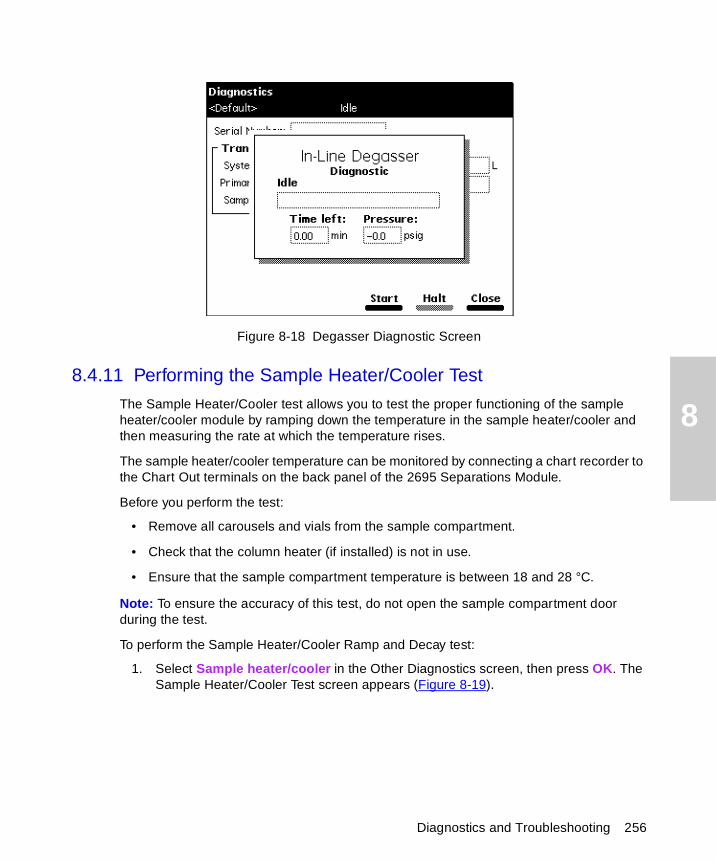
8
Figure 8-18 Degasser Diagnostic Screen
8.4.11 Performing the Sample Heater/Cooler Test
The Sample Heater/Cooler test allows you to test the proper functioning of the sample heater/cooler module by ramping down the temperature in the sample heater/cooler and then measuring the rate at which the temperature rises.
The sample heater/cooler temperature can be monitored by connecting a chart recorder to the Chart Out terminals on the back panel of the 2695 Separations Module.
Before you perform the test:
• Remove all carousels and vials from the sample compartment.
• Check that the column heater (if installed) is not in use.
• Ensure that the sample compartment temperature is between 18 and 28 °C.
Note: To ensure the accuracy of this test, do not open the sample compartment door during the test.
To perform the Sample Heater/Cooler Ramp and Decay test:
1. Select Sample heater/cooler in the Other Diagnostics screen, then press OK. The Sample Heater/Cooler Test screen appears (Figure 8-19).
Diagnostics and Troubleshooting 256
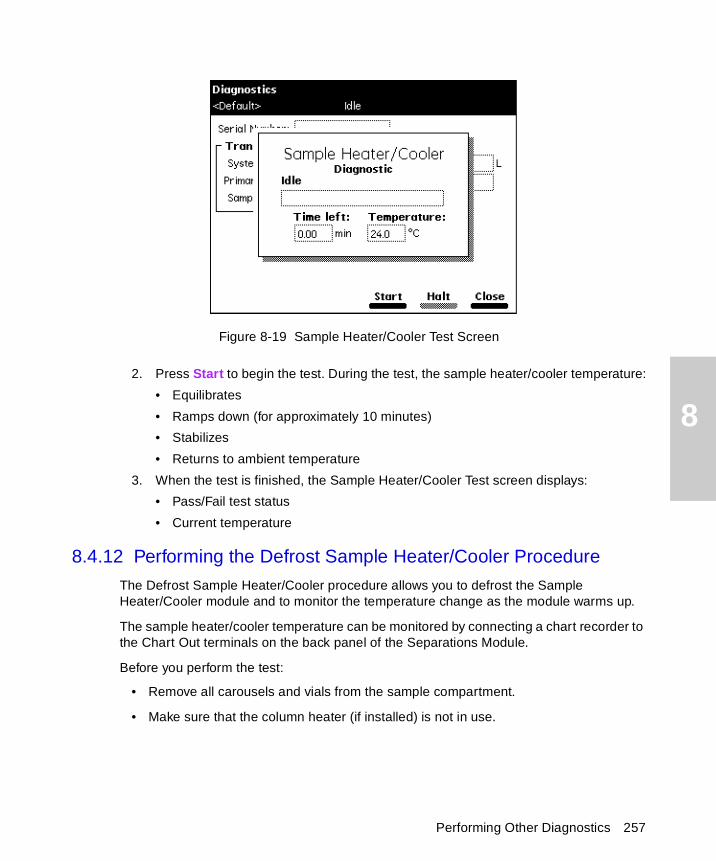
8
Figure 8-19 Sample Heater/Cooler Test Screen
2. Press Start to begin the test. During the test, the sample heater/cooler temperature:
• Equilibrates
• Ramps down (for approximately 10 minutes)
• Stabilizes
• Returns to ambient temperature
3. When the test is finished, the Sample Heater/Cooler Test screen displays:
• Pass/Fail test status
• Current temperature
8.4.12 Performing the Defrost Sample Heater/Cooler Procedure
The Defrost Sample Heater/Cooler procedure allows you to defrost the Sample Heater/Cooler module and to monitor the temperature change as the module warms up.
The sample heater/cooler temperature can be monitored by connecting a chart recorder to the Chart Out terminals on the back panel of the Separations Module.
Before you perform the test:
• Remove all carousels and vials from the sample compartment.
• Make sure that the column heater (if installed) is not in use.
Performing Other Diagnostics 257
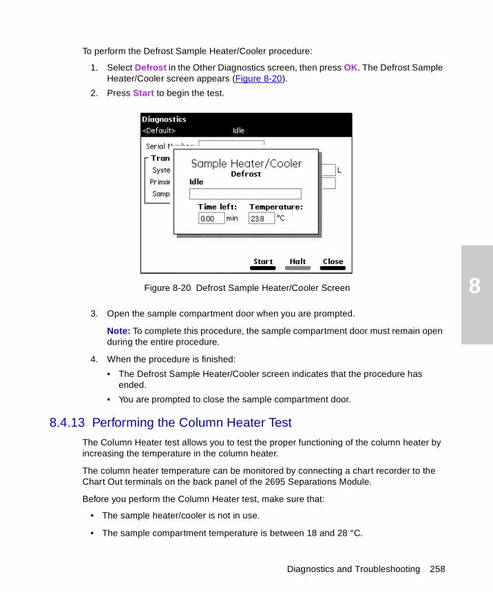
8
To perform the Defrost Sample Heater/Cooler procedure:
1. Select Defrost in the Other Diagnostics screen, then press OK. The Defrost Sample Heater/Cooler screen appears (Figure 8-20).
2. Press Start to begin the test.
Figure 8-20 Defrost Sample Heater/Cooler Screen
3. Open the sample compartment door when you are prompted.
Note: To complete this procedure, the sample compartment door must remain open during the entire procedure.
4. When the procedure is finished:
• The Defrost Sample Heater/Cooler screen indicates that the procedure has ended.
• You are prompted to close the sample compartment door.
8.4.13 Performing the Column Heater Test
The Column Heater test allows you to test the proper functioning of the column heater by increasing the temperature in the column heater.
The column heater temperature can be monitored by connecting a chart recorder to the Chart Out terminals on the back panel of the 2695 Separations Module.
Before you perform the Column Heater test, make sure that:
• The sample heater/cooler is not in use.
• The sample compartment temperature is between 18 and 28 °C.
Diagnostics and Troubleshooting 258
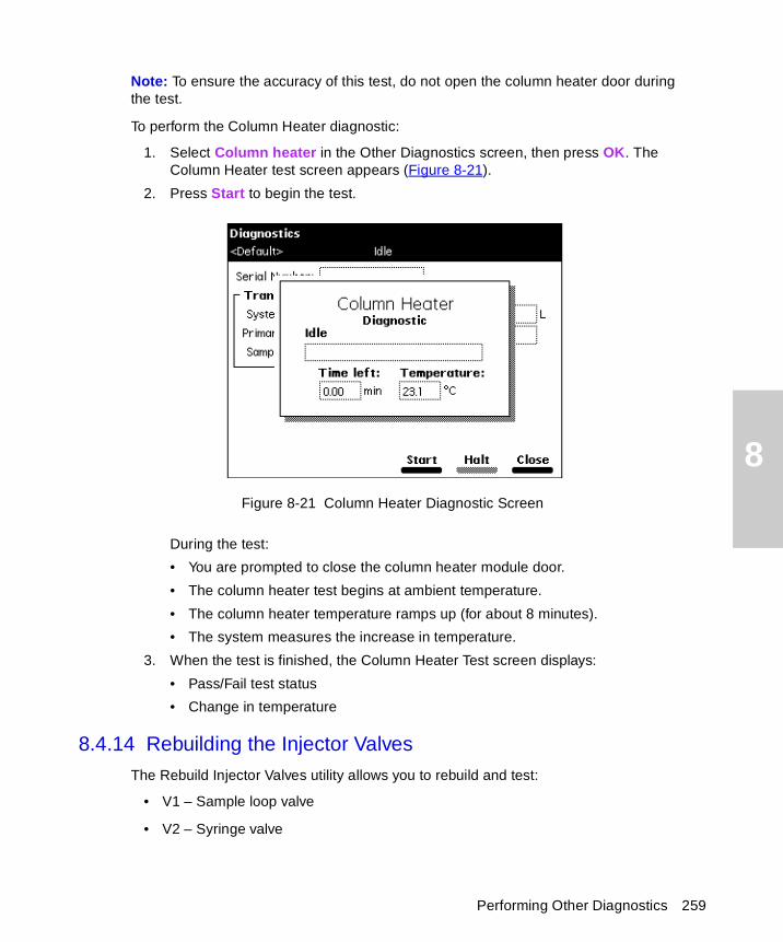
8
Note: To ensure the accuracy of this test, do not open the column heater door during the test.
To perform the Column Heater diagnostic:
1. Select Column heater in the Other Diagnostics screen, then press OK. The Column Heater test screen appears (Figure 8-21).
2. Press Start to begin the test.
Figure 8-21 Column Heater Diagnostic Screen
During the test:
• You are prompted to close the column heater module door.
• The column heater test begins at ambient temperature.
• The column heater temperature ramps up (for about 8 minutes).
• The system measures the increase in temperature.
3. When the test is finished, the Column Heater Test screen displays:
• Pass/Fail test status
• Change in temperature
8.4.14 Rebuilding the Injector Valves
The Rebuild Injector Valves utility allows you to rebuild and test:
• V1 – Sample loop valve
• V2 – Syringe valve
Performing Other Diagnostics 259
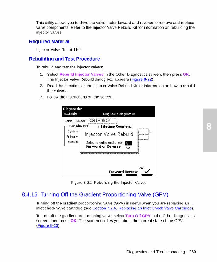
8
This utility allows you to drive the valve motor forward and reverse to remove and replace valve components. Refer to the Injector Valve Rebuild Kit for information on rebuilding the injector valves.
Required Material
Injector Valve Rebuild Kit
Rebuilding and Test Procedure
To rebuild and test the injector valves:
1. Select Rebuild Injector Valves in the Other Diagnostics screen, then press OK. The Injector Valve Rebuild dialog box appears (Figure 8-22).
2. Read the directions in the Injector Valve Rebuild Kit for information on how to rebuild the valves.
3. Follow the instructions on the screen.
Figure 8-22 Rebuilding the Injector Valves
8.4.15 Turning Off the Gradient Proportioning Valve (GPV)
Turning off the gradient proportioning valve (GPV) is useful when you are replacing an inlet check valve cartridge (see Section 7.2.6, Replacing an Inlet Check Valve Cartridge).
To turn off the gradient proportioning valve, select Turn Off GPV in the Other Diagnostics screen, then press OK. The screen notifies you about the current state of the GPV (Figure 8-23).
G98SM4582M
Diagnostics and Troubleshooting 260
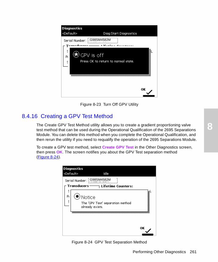
8
Figure 8-23 Turn Off GPV Utility
8.4.16 Creating a GPV Test Method
The Create GPV Test Method utility allows you to create a gradient proportioning valve test method that can be used during the Operational Qualification of the 2695 Separations Module. You can delete this method when you complete the Operational Qualification, and then rerun the utility if you need to requalify the operation of the 2695 Separations Module.
To create a GPV test method, select Create GPV Test in the Other Diagnostics screen, then press OK. The screen notifies you about the GPV Test separation method (Figure 8-24).
Figure 8-24 GPV Test Separation Method
G98SM4582M
G98SM4582M
Performing Other Diagnostics 261
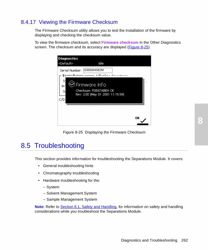
8
8.4.17 Viewing the Firmware Checksum
The Firmware Checksum utility allows you to test the installation of the firmware by displaying and checking the checksum value.
To view the firmware checksum, select Firmware checksum in the Other Diagnostics screen. The checksum and its accuracy are displayed (Figure 8-25).
Figure 8-25 Displaying the Firmware Checksum
8.5 Troubleshooting
This section provides information for troubleshooting the Separations Module. It covers:
• General troubleshooting hints
• Chromatography troubleshooting
• Hardware troubleshooting for the:
– System
– Solvent Management System
– Sample Management System
Note: Refer to Section 8.1, Safety and Handling, for information on safety and handling considerations while you troubleshoot the Separations Module.
G98SM4582M
Diagnostics and Troubleshooting 262
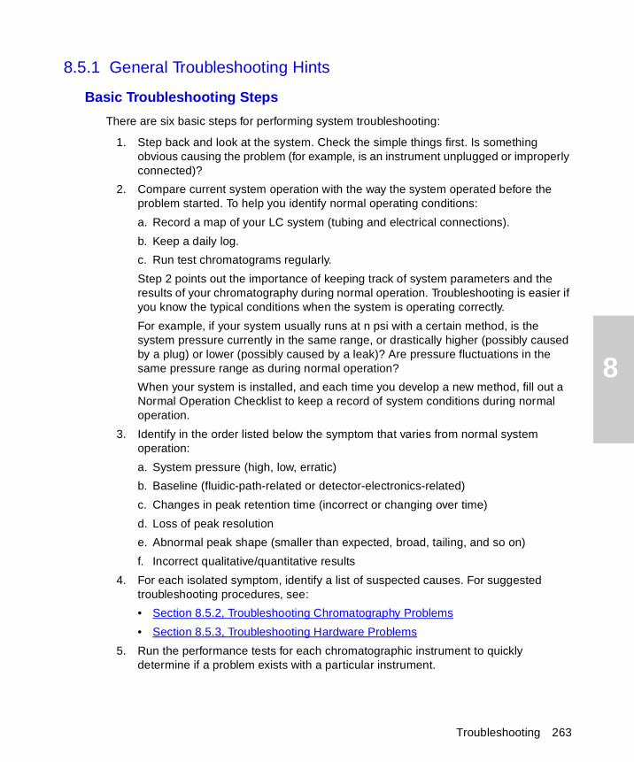
8
8.5.1 General Troubleshooting Hints
Basic Troubleshooting Steps
There are six basic steps for performing system troubleshooting:
1. Step back and look at the system. Check the simple things first. Is something obvious causing the problem (for example, is an instrument unplugged or improperly connected)?
2. Compare current system operation with the way the system operated before the problem started. To help you identify normal operating conditions:
a. Record a map of your LC system (tubing and electrical connections).
b. Keep a daily log.
c. Run test chromatograms regularly.
Step 2 points out the importance of keeping track of system parameters and the results of your chromatography during normal operation. Troubleshooting is easier if you know the typical conditions when the system is operating correctly.
For example, if your system usually runs at n psi with a certain method, is the system pressure currently in the same range, or drastically higher (possibly caused by a plug) or lower (possibly caused by a leak)? Are pressure fluctuations in the same pressure range as during normal operation?
When your system is installed, and each time you develop a new method, fill out a Normal Operation Checklist to keep a record of system conditions during normal operation.
3. Identify in the order listed below the symptom that varies from normal system operation:
a. System pressure (high, low, erratic)
b. Baseline (fluidic-path-related or detector-electronics-related)
c. Changes in peak retention time (incorrect or changing over time)
d. Loss of peak resolution
e. Abnormal peak shape (smaller than expected, broad, tailing, and so on)
f. Incorrect qualitative/quantitative results
4. For each isolated symptom, identify a list of suspected causes. For suggested troubleshooting procedures, see:
• Section 8.5.2, Troubleshooting Chromatography Problems
• Section 8.5.3, Troubleshooting Hardware Problems
5. Run the performance tests for each chromatographic instrument to quickly determine if a problem exists with a particular instrument.
Troubleshooting 263
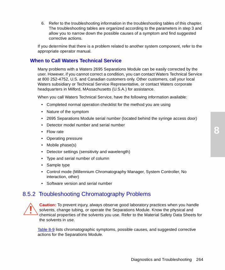
8
6. Refer to the troubleshooting information in the troubleshooting tables of this chapter. The troubleshooting tables are organized according to the parameters in step 3 and allow you to narrow down the possible causes of a symptom and find suggested corrective actions.
If you determine that there is a problem related to another system component, refer to the appropriate operator manual.
When to Call Waters Technical Service
Many problems with a Waters 2695 Separations Module can be easily corrected by the user. However, if you cannot correct a condition, you can contact Waters Technical Service at 800 252-4752, U.S. and Canadian customers only. Other customers, call your local Waters subsidiary or Technical Service Representative, or contact Waters corporate headquarters in Milford, MAssachusetts (U.S.A.) for assistance.
When you call Waters Technical Service, have the following information available:
• Completed normal operation checklist for the method you are using
• Nature of the symptom
• 2695 Separations Module serial number (located behind the syringe access door)
• Detector model number and serial number
• Flow rate
• Operating pressure
• Mobile phase(s)
• Detector settings (sensitivity and wavelength)
• Type and serial number of column
• Sample type
• Control mode (Millennium Chromatography Manager, System Controller, No interaction, other)
• Software version and serial number
8.5.2 Troubleshooting Chromatography Problems
Table 8-9 lists chromatographic symptoms, possible causes, and suggested corrective actions for the Separations Module.
Caution: To prevent injury, always observe good laboratory practices when you handle solvents, change tubing, or operate the Separations Module. Know the physical and chemical properties of the solvents you use. Refer to the Material Safety Data Sheets for the solvents in use.
Diagnostics and Troubleshooting 264
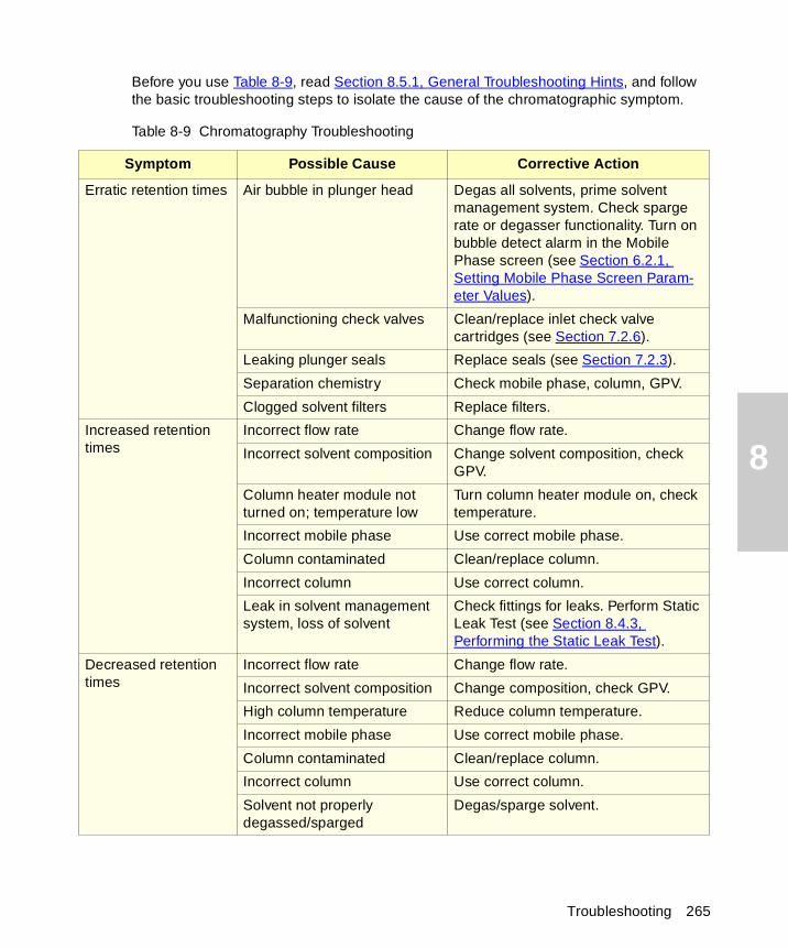
8
Before you use Table 8-9, read Section 8.5.1, General Troubleshooting Hints, and follow the basic troubleshooting steps to isolate the cause of the chromatographic symptom.
Table 8-9 Chromatography Troubleshooting
Symptom Possible Cause Corrective Action
Erratic retention times Air bubble in plunger head Degas all solvents, prime solvent management system. Check sparge rate or degasser functionality. Turn on bubble detect alarm in the Mobile Phase screen (see Section 6.2.1, Setting Mobile Phase Screen Param-eter Values).
Malfunctioning check valves Clean/replace inlet check valve cartridges (see Section 7.2.6).
Leaking plunger seals Replace seals (see Section 7.2.3).
Separation chemistry Check mobile phase, column, GPV.
Clogged solvent filters Replace filters.
Increased retention times
Incorrect flow rate Change flow rate.
Incorrect solvent composition Change solvent composition, check GPV.
Column heater module not turned on; temperature low
Turn column heater module on, check temperature.
Incorrect mobile phase Use correct mobile phase.
Column contaminated Clean/replace column.
Incorrect column Use correct column.
Leak in solvent management system, loss of solvent
Check fittings for leaks. Perform Static Leak Test (see Section 8.4.3, Performing the Static Leak Test).
Decreased retention times
Incorrect flow rate Change flow rate.
Incorrect solvent composition Change composition, check GPV.
High column temperature Reduce column temperature.
Incorrect mobile phase Use correct mobile phase.
Column contaminated Clean/replace column.
Incorrect column Use correct column.
Solvent not properly degassed/sparged
Degas/sparge solvent.
Troubleshooting 265
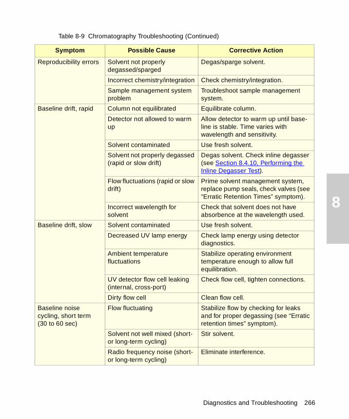
8
Reproducibility errors Solvent not properly degassed/sparged
Degas/sparge solvent.
Incorrect chemistry/integration Check chemistry/integration.
Sample management system problem
Troubleshoot sample management system.
Baseline drift, rapid Column not equilibrated Equilibrate column.
Detector not allowed to warm up
Allow detector to warm up until base-line is stable. Time varies with wavelength and sensitivity.
Solvent contaminated Use fresh solvent.
Solvent not properly degassed (rapid or slow drift)
Degas solvent. Check inline degasser (see Section 8.4.10, Performing the Inline Degasser Test).
Flow fluctuations (rapid or slow drift)
Prime solvent management system, replace pump seals, check valves (see “Erratic Retention Times” symptom).
Incorrect wavelength for solvent
Check that solvent does not have absorbence at the wavelength used.
Baseline drift, slow Solvent contaminated Use fresh solvent.
Decreased UV lamp energy Check lamp energy using detector diagnostics.
Ambient temperature fluctuations
Stabilize operating environment temperature enough to allow full equilibration.
UV detector flow cell leaking (internal, cross-port)
Check flow cell, tighten connections.
Dirty flow cell Clean flow cell.
Baseline noise cycling, short term (30 to 60 sec)
Flow fluctuating Stabilize flow by checking for leaks and for proper degassing (see “Erratic retention times” symptom).
Solvent not well mixed (short- or long-term cycling)
Stir solvent.
Radio frequency noise (short- or long-term cycling)
Eliminate interference.
Table 8-9 Chromatography Troubleshooting (Continued)
Symptom Possible Cause Corrective Action
Diagnostics and Troubleshooting 266
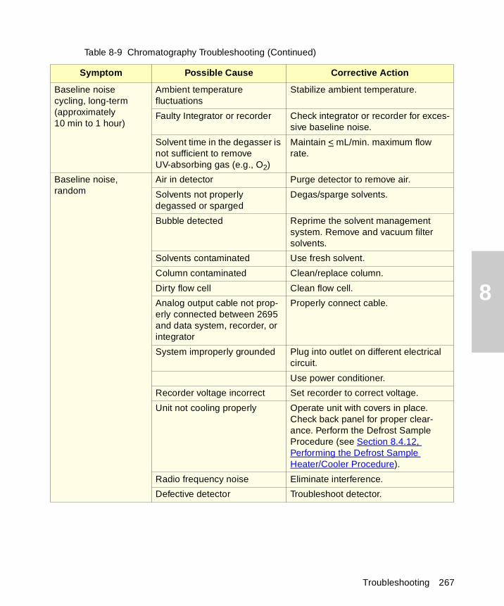
8
Baseline noise cycling, long-term (approximately 10 min to 1 hour)
Ambient temperature fluctuations
Stabilize ambient temperature.
Faulty Integrator or recorder Check integrator or recorder for exces-sive baseline noise.
Solvent time in the degasser is not sufficient to remove UV-absorbing gas (e.g., O2)
Maintain < mL/min. maximum flow rate.
Baseline noise, random
Air in detector Purge detector to remove air.
Solvents not properly degassed or sparged
Degas/sparge solvents.
Bubble detected Reprime the solvent management system. Remove and vacuum filter solvents.
Solvents contaminated Use fresh solvent.
Column contaminated Clean/replace column.
Dirty flow cell Clean flow cell.
Analog output cable not prop-erly connected between 2695 and data system, recorder, or integrator
Properly connect cable.
System improperly grounded Plug into outlet on different electrical circuit.
Use power conditioner.
Recorder voltage incorrect Set recorder to correct voltage.
Unit not cooling properly Operate unit with covers in place. Check back panel for proper clear-ance. Perform the Defrost Sample Procedure (see Section 8.4.12, Performing the Defrost Sample Heater/Cooler Procedure).
Radio frequency noise Eliminate interference.
Defective detector Troubleshoot detector.
Table 8-9 Chromatography Troubleshooting (Continued)
Symptom Possible Cause Corrective Action
Troubleshooting 267
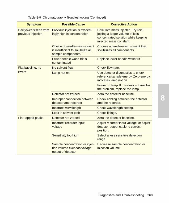
8
Carryover is seen from previous injection
Previous injection is exceed-ingly high in concentration
Calculate mass injected. Try rein-jecting a larger volume of less concentrated solution while keeping injected mass constant.
Choice of needle-wash solvent is insufficient to solubilize all sample components.
Choose a needle-wash solvent that solubilizes all components.
Lower needle-wash frit is contaminated
Replace lower needle wash frit
Flat baseline, no peaks
No solvent flow Check flow rate.
Lamp not on Use detector diagnostics to check reference/sample energy. Zero energy indicates lamp not on.
Power on lamp. If this does not resolve the problem, replace the lamp.
Detector not zeroed Zero the detector baseline.
Improper connection between detector and recorder
Check cabling between the detector and the recorder.
Incorrect wavelength Check wavelength setting.
Leak in solvent path Check fittings.
Flat-topped peaks Detector not zeroed Zero the detector baseline.
Incorrect recorder input voltage
Adjust recorder input voltage, or adjust detector output cable to correct position.
Sensitivity too high Select a less sensitive detection range.
Sample concentration or injec-tion volume exceeds voltage output of detector
Decrease sample concentration or injection volume.
Table 8-9 Chromatography Troubleshooting (Continued)
Symptom Possible Cause Corrective Action
Diagnostics and Troubleshooting 268
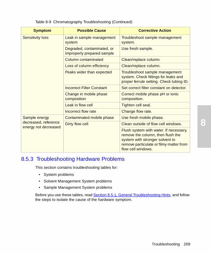
8
8.5.3 Troubleshooting Hardware Problems
This section contains troubleshooting tables for:
• System problems
• Solvent Management System problems
• Sample Management System problems
Before you use these tables, read Section 8.5.1, General Troubleshooting Hints, and follow the steps to isolate the cause of the hardware symptom.
Sensitivity loss Leak in sample management system
Troubleshoot sample management system.
Degraded, contaminated, or improperly prepared sample
Use fresh sample.
Column contaminated Clean/replace column.
Loss of column efficiency Clean/replace column.
Peaks wider than expected Troubleshoot sample management system. Check fittings for leaks and proper ferrule setting. Check tubing ID.
Incorrect Filter Constant Set correct filter constant on detector.
Change in mobile phase composition
Correct mobile phase pH or ionic composition.
Leak in flow cell Tighten cell seal.
Incorrect flow rate Change flow rate.
Sample energy decreased, reference energy not decreased
Contaminated mobile phase Use fresh mobile phase.
Dirty flow cell Clean outside of flow cell windows.
Flush system with water. If necessary, remove the column, then flush the system with stronger solvent to remove particulate or filmy matter from flow cell windows.
Table 8-9 Chromatography Troubleshooting (Continued)
Symptom Possible Cause Corrective Action
Troubleshooting 269
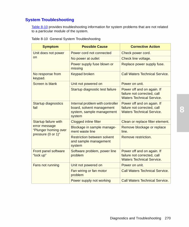
8
System Troubleshooting
Table 8-10 provides troubleshooting information for system problems that are not related to a particular module of the system.
Table 8-10 General System Troubleshooting
Symptom Possible Cause Corrective Action
Unit does not power on
Power cord not connected Check power cord.
No power at outlet Check line voltage.
Power supply fuse blown or missing
Replace power supply fuse.
No response from keypad.
Keypad broken Call Waters Technical Service.
Screen is blank Unit not powered on Power on unit.
Startup diagnostic test failure Power off and on again. If failure not corrected, call Waters Technical Service.
Startup diagnostics fail
Internal problem with controller board, solvent management system, sample management system
Power off and on again. If failure not corrected, call Waters Technical Service.
Startup failure with error message “Plunger homing over pressure (0 or 1)”
Clogged inline filter Clean or replace filter element.
Blockage in sample manage-ment waste line
Remove blockage or replace line.
Restriction between solvent and sample management system
Remove restriction.
Front panel software “lock up”
Software problem, power line problem
Power off and on again. If failure not corrected, call Waters Technical Service.
Fans not running Unit not powered on Power on unit.
Fan wiring or fan motor problem
Call Waters Technical Service.
Power supply not working Call Waters Technical Service.
Diagnostics and Troubleshooting 270
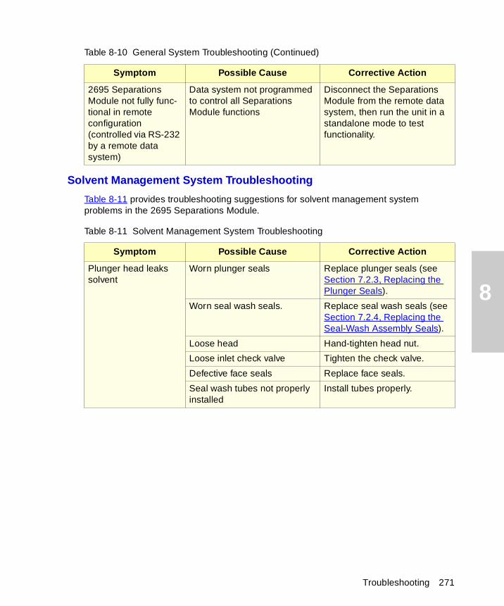
8
Solvent Management System Troubleshooting
Table 8-11 provides troubleshooting suggestions for solvent management system problems in the 2695 Separations Module.
2695 Separations Module not fully func-tional in remote configuration (controlled via RS-232 by a remote data system)
Data system not programmed to control all Separations Module functions
Disconnect the Separations Module from the remote data system, then run the unit in a standalone mode to test functionality.
Table 8-11 Solvent Management System Troubleshooting
Symptom Possible Cause Corrective Action
Plunger head leaks solvent
Worn plunger seals Replace plunger seals (see Section 7.2.3, Replacing the Plunger Seals).
Worn seal wash seals. Replace seal wash seals (see Section 7.2.4, Replacing the Seal-Wash Assembly Seals).
Loose head Hand-tighten head nut.
Loose inlet check valve Tighten the check valve.
Defective face seals Replace face seals.
Seal wash tubes not properly installed
Install tubes properly.
Table 8-10 General System Troubleshooting (Continued)
Symptom Possible Cause Corrective Action
Troubleshooting 271
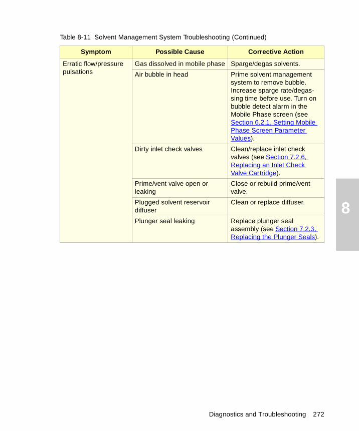
8
Erratic flow/pressure pulsations
Gas dissolved in mobile phase Sparge/degas solvents.
Air bubble in head Prime solvent management system to remove bubble. Increase sparge rate/degas-sing time before use. Turn on bubble detect alarm in the Mobile Phase screen (see Section 6.2.1, Setting Mobile Phase Screen Parameter Values).
Dirty inlet check valves Clean/replace inlet check valves (see Section 7.2.6, Replacing an Inlet Check Valve Cartridge).
Prime/vent valve open or leaking
Close or rebuild prime/vent valve.
Plugged solvent reservoir diffuser
Clean or replace diffuser.
Plunger seal leaking Replace plunger seal assembly (see Section 7.2.3, Replacing the Plunger Seals).
Table 8-11 Solvent Management System Troubleshooting (Continued)
Symptom Possible Cause Corrective Action
Diagnostics and Troubleshooting 272
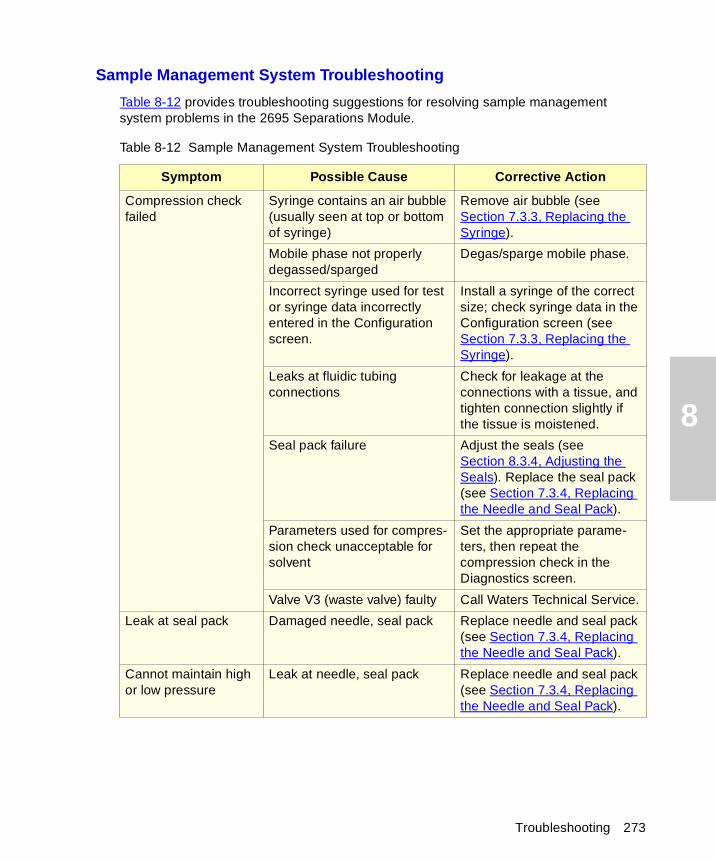
8
Sample Management System Troubleshooting
Table 8-12 provides troubleshooting suggestions for resolving sample management system problems in the 2695 Separations Module.
Table 8-12 Sample Management System Troubleshooting
Symptom Possible Cause Corrective Action
Compression check failed
Syringe contains an air bubble (usually seen at top or bottom of syringe)
Remove air bubble (see Section 7.3.3, Replacing the Syringe).
Mobile phase not properly degassed/sparged
Degas/sparge mobile phase.
Incorrect syringe used for test or syringe data incorrectly entered in the Configuration screen.
Install a syringe of the correct size; check syringe data in the Configuration screen (see Section 7.3.3, Replacing the Syringe).
Leaks at fluidic tubing connections
Check for leakage at the connections with a tissue, and tighten connection slightly if the tissue is moistened.
Seal pack failure Adjust the seals (see Section 8.3.4, Adjusting the Seals). Replace the seal pack (see Section 7.3.4, Replacing the Needle and Seal Pack).
Parameters used for compres-sion check unacceptable for solvent
Set the appropriate parame-ters, then repeat the compression check in the Diagnostics screen.
Valve V3 (waste valve) faulty Call Waters Technical Service.
Leak at seal pack Damaged needle, seal pack Replace needle and seal pack (see Section 7.3.4, Replacing the Needle and Seal Pack).
Cannot maintain high or low pressure
Leak at needle, seal pack Replace needle and seal pack (see Section 7.3.4, Replacing the Needle and Seal Pack).
Troubleshooting 273
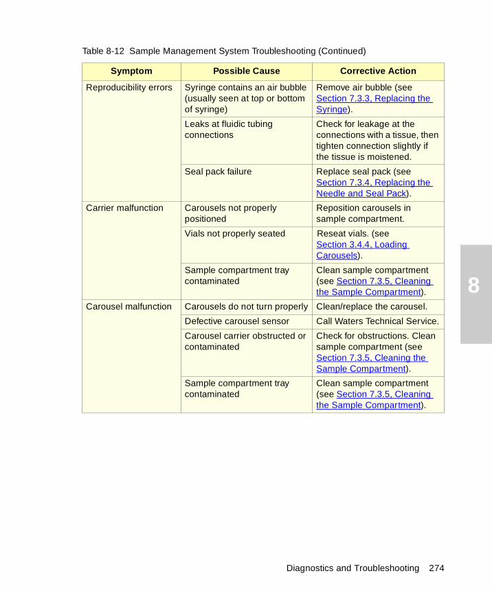
8
Reproducibility errors Syringe contains an air bubble (usually seen at top or bottom of syringe)
Remove air bubble (see Section 7.3.3, Replacing the Syringe).
Leaks at fluidic tubing connections
Check for leakage at the connections with a tissue, then tighten connection slightly if the tissue is moistened.
Seal pack failure Replace seal pack (see Section 7.3.4, Replacing the Needle and Seal Pack).
Carrier malfunction Carousels not properly positioned
Reposition carousels in sample compartment.
Vials not properly seated Reseat vials. (see Section 3.4.4, Loading Carousels).
Sample compartment tray contaminated
Clean sample compartment (see Section 7.3.5, Cleaning the Sample Compartment).
Carousel malfunction Carousels do not turn properly Clean/replace the carousel.
Defective carousel sensor Call Waters Technical Service.
Carousel carrier obstructed or contaminated
Check for obstructions. Clean sample compartment (see Section 7.3.5, Cleaning the Sample Compartment).
Sample compartment tray contaminated
Clean sample compartment (see Section 7.3.5, Cleaning the Sample Compartment).
Table 8-12 Sample Management System Troubleshooting (Continued)
Symptom Possible Cause Corrective Action
Diagnostics and Troubleshooting 274
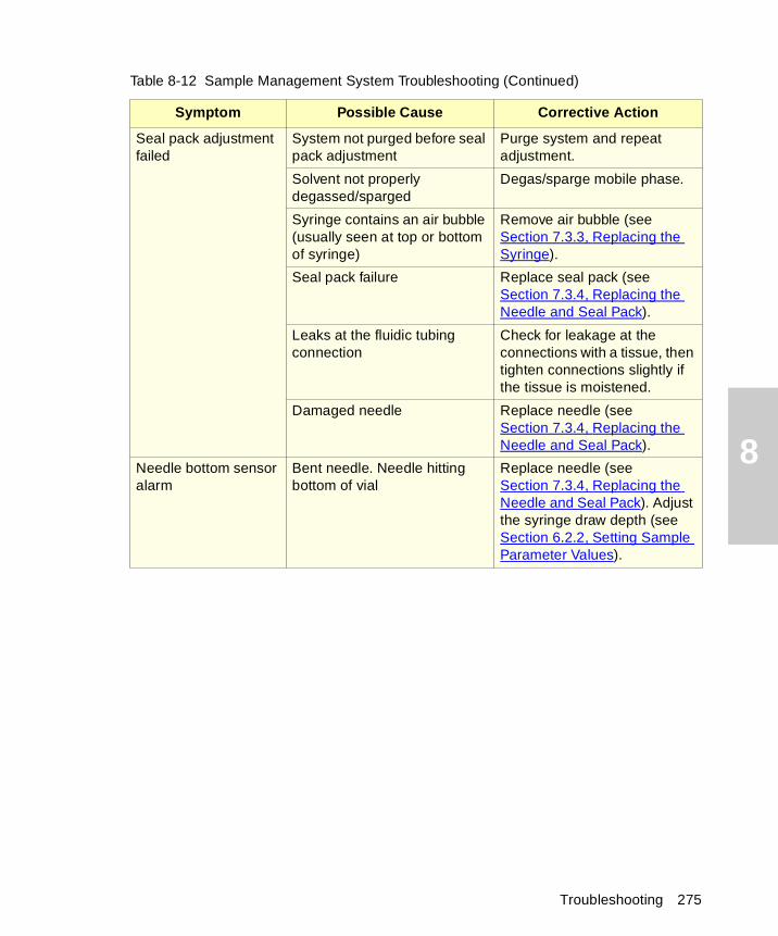
8
Seal pack adjustment failed
System not purged before seal pack adjustment
Purge system and repeat adjustment.
Solvent not properly degassed/sparged
Degas/sparge mobile phase.
Syringe contains an air bubble (usually seen at top or bottom of syringe)
Remove air bubble (see Section 7.3.3, Replacing the Syringe).
Seal pack failure Replace seal pack (see Section 7.3.4, Replacing the Needle and Seal Pack).
Leaks at the fluidic tubing connection
Check for leakage at the connections with a tissue, then tighten connections slightly if the tissue is moistened.
Damaged needle Replace needle (see Section 7.3.4, Replacing the Needle and Seal Pack).
Needle bottom sensor alarm
Bent needle. Needle hitting bottom of vial
Replace needle (see Section 7.3.4, Replacing the Needle and Seal Pack). Adjust the syringe draw depth (see Section 6.2.2, Setting Sample Parameter Values).
Table 8-12 Sample Management System Troubleshooting (Continued)
Symptom Possible Cause Corrective Action
Troubleshooting 275
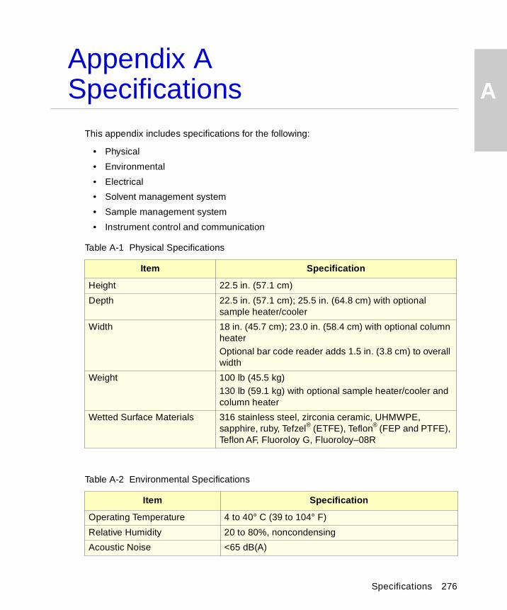
A
Appendix ASpecificationsThis appendix includes specifications for the following:
• Physical
• Environmental
• Electrical
• Solvent management system
• Sample management system
• Instrument control and communication
Table A-1 Physical Specifications
Item Specification
Height 22.5 in. (57.1 cm)
Depth 22.5 in. (57.1 cm); 25.5 in. (64.8 cm) with optional sample heater/cooler
Width 18 in. (45.7 cm); 23.0 in. (58.4 cm) with optional column heaterOptional bar code reader adds 1.5 in. (3.8 cm) to overall width
Weight 100 lb (45.5 kg)130 lb (59.1 kg) with optional sample heater/cooler and column heater
Wetted Surface Materials 316 stainless steel, zirconia ceramic, UHMWPE, sapphire, ruby, Tefzel® (ETFE), Teflon® (FEP and PTFE), Teflon AF, Fluoroloy G, Fluoroloy–08R
Table A-2 Environmental Specifications
Item Specification
Operating Temperature 4 to 40° C (39 to 104° F)
Relative Humidity 20 to 80%, noncondensing
Acoustic Noise <65 dB(A)
Specifications 276
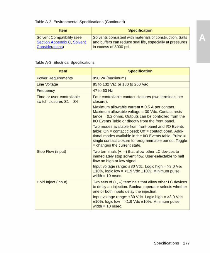
A
Solvent Compatibility (see Section Appendix C, Solvent Considerations)Solvents consistent with materials of construction. Salts and buffers can reduce seal life, especially at pressures in excess of 3000 psi.
Table A-3 Electrical Specifications
Item Specification
Power Requirements 950 VA (maximum)
Line Voltage 85 to 132 Vac or 180 to 250 Vac
Frequency 47 to 63 Hz
Time or user-controllable switch closures S1 – S4
Four controllable contact closures (two terminals per closure).Maximum allowable current = 0.5 A per contact. Maximum allowable voltage = 30 Vdc. Contact resis-tance = 0.2 ohms. Outputs can be controlled from the I/O Events Table or directly from the front panel.Two modes available from front panel and I/O Events table: On = contact closed; Off = contact open. Addi-tional modes available in the I/O Events table: Pulse = single contact closure for programmable period; Toggle = changes the current state.
Stop Flow (input) Two terminals (+, –) that allow other LC devices to immediately stop solvent flow. User-selectable to halt flow on high or low signal.Input voltage range: ±30 Vdc. Logic high = >3.0 Vdc ±10%, logic low = <1.9 Vdc ±10%. Minimum pulse width = 10 msec.
Hold Inject (input) Two sets of (+, –) terminals that allow other LC devices to delay an injection. Boolean operator selects whether one or both inputs delay the injection.Input voltage range: ±30 Vdc. Logic high = >3.0 Vdc ±10%, logic low = <1.9 Vdc ±10%. Minimum pulse width = 10 msec.
Table A-2 Environmental Specifications (Continued)
Item Specification
Specifications 277
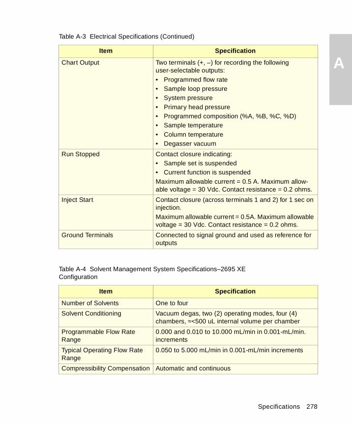
A
Chart Output Two terminals (+, –) for recording the following user-selectable outputs:• Programmed flow rate• Sample loop pressure• System pressure• Primary head pressure• Programmed composition (%A, %B, %C, %D)• Sample temperature• Column temperature• Degasser vacuumRun Stopped Contact closure indicating:• Sample set is suspended• Current function is suspendedMaximum allowable current = 0.5 A. Maximum allow-able voltage = 30 Vdc. Contact resistance = 0.2 ohms.
Inject Start Contact closure (across terminals 1 and 2) for 1 sec on injection.Maximum allowable current = 0.5A. Maximum allowable voltage = 30 Vdc. Contact resistance = 0.2 ohms.
Ground Terminals Connected to signal ground and used as reference for outputs
Table A-4 Solvent Management System Specifications–2695 XEConfiguration
Item Specification
Number of Solvents One to four
Solvent Conditioning Vacuum degas, two (2) operating modes, four (4) chambers, ≈<500 uL internal volume per chamber
Programmable Flow Rate Range
0.000 and 0.010 to 10.000 mL/min in 0.001-mL/min. increments
Typical Operating Flow Rate Range
0.050 to 5.000 mL/min in 0.001-mL/min increments
Compressibility Compensation Automatic and continuous
Table A-3 Electrical Specifications (Continued)
Item Specification
Specifications 278

A
Effective System Delay Volume<650 µL, independent of backpressure @ 1 mL/min
Plunger Seal Wash Integral, active, programmable
Gradient Profiles Eleven (11) gradient curves [including linear, step (2 curves), concave (4 curves), and convex (4 curves)]
Dry Prime/Wet Prime Automatic, front panel control
Flow Ramping Time (0.01 to 30.00 min in 0.01-min increments) to reach maximum flow rate
Maximum Operating Pressure 5000 psi (345 bar) (0.010 to 3.000 mL/min) Program-mable upper and lower limits. Pressure fall-off at >3.000 mL/min.
Pressure Ripple ≤2.5% (1 mL/min, degassed methanol, at 1700 psi backpressure)
Composition Range 0.0 – 100.0 in 0.1% increments
Composition Accuracy ±0.5% absolute, independent of backpressure (Propor-tioning Valve Pair Test [degassed methanol:methanol/propylparaben, 2 mL/min, 254 nm])
Composition Precision ≤0.15% RSD or ≤0.02 min SD, whichever is greater, based on retention time. (Degassed methanol:water 60:40 Dial-a-Mix, 1 mL/min, six replicates, phenone mix, 254 nm.)
Flow Precision ≤0.075% RSD or ≤0.02 min SD, based on retention time (N = 6) or volumetric measures (0.200 to 5.000 mL/min), isocratic premix
Flow Accuracy ±1% or 10 µL/min, whichever is greater, (0.200 to 5.000 mL/ min), degassed methanol, at 600 psi backpressure
Table A-5 Sample Management System Specifications
Item Specification
Number of Sample Vials 120 vials, configured in 5 carousels of 24 vials each
Number of Sample Injections 1 to 99 injections per sample vial
Table A-4 Solvent Management System Specifications–2695 XEConfiguration (Continued)
Item Specification
Specifications 279
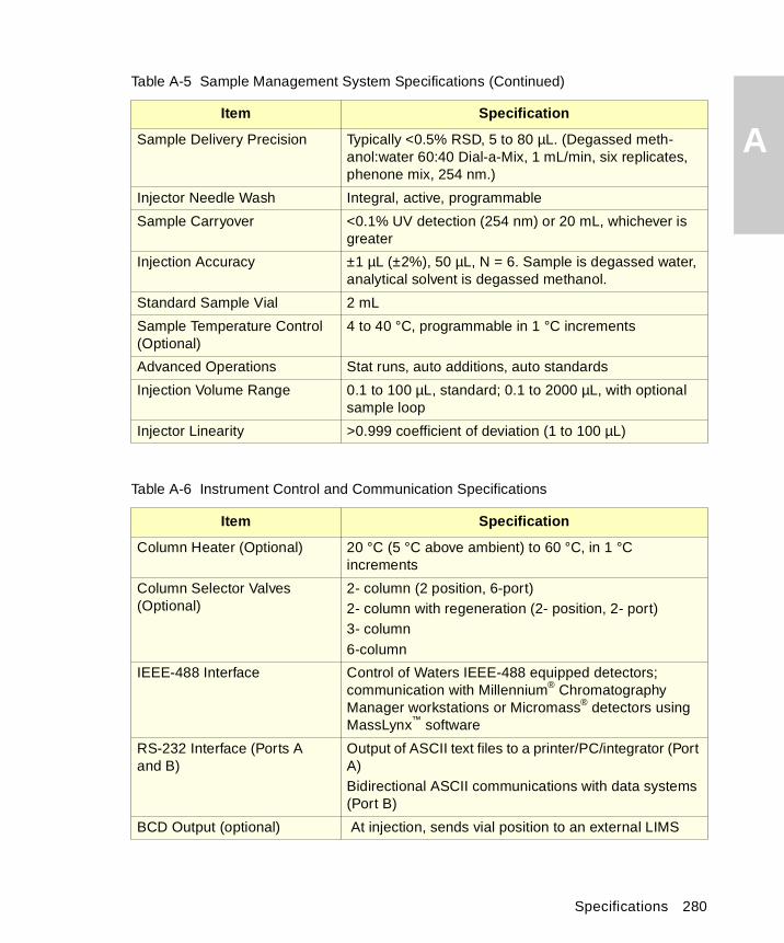
A
Sample Delivery Precision Typically <0.5% RSD, 5 to 80 µL. (Degassed meth-anol:water 60:40 Dial-a-Mix, 1 mL/min, six replicates, phenone mix, 254 nm.)Injector Needle Wash Integral, active, programmable
Sample Carryover <0.1% UV detection (254 nm) or 20 mL, whichever is greater
Injection Accuracy ±1 µL (±2%), 50 µL, N = 6. Sample is degassed water, analytical solvent is degassed methanol.
Standard Sample Vial 2 mL
Sample Temperature Control (Optional)
4 to 40 °C, programmable in 1 °C increments
Advanced Operations Stat runs, auto additions, auto standards
Injection Volume Range 0.1 to 100 µL, standard; 0.1 to 2000 µL, with optional sample loop
Injector Linearity >0.999 coefficient of deviation (1 to 100 µL)
Table A-6 Instrument Control and Communication Specifications
Item Specification
Column Heater (Optional) 20 °C (5 °C above ambient) to 60 °C, in 1 °C increments
Column Selector Valves (Optional)
2- column (2 position, 6-port)2- column with regeneration (2- position, 2- port)3- column6-column
IEEE-488 Interface Control of Waters IEEE-488 equipped detectors; communication with Millennium® Chromatography Manager workstations or Micromass® detectors using MassLynx™ software
RS-232 Interface (Ports Aand B)
Output of ASCII text files to a printer/PC/integrator (Port A)Bidirectional ASCII communications with data systems (Port B)
BCD Output (optional) At injection, sends vial position to an external LIMS
Table A-5 Sample Management System Specifications (Continued)
Item Specification
Specifications 280
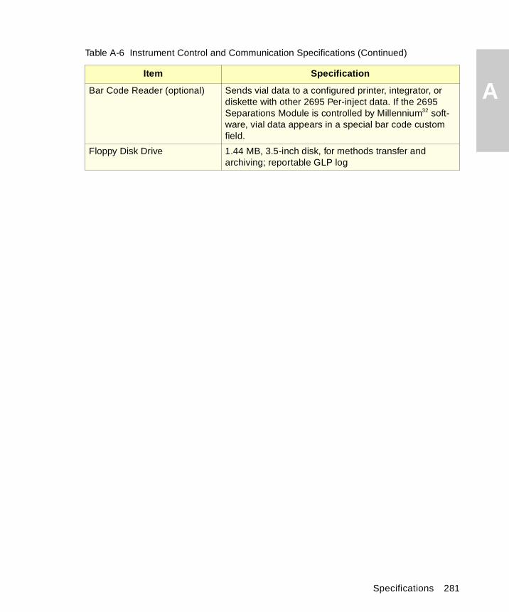
A
Bar Code Reader (optional) Sends vial data to a configured printer, integrator, or diskette with other 2695 Per-inject data. If the 2695 Separations Module is controlled by Millennium32 soft-ware, vial data appears in a special bar code custom field.Floppy Disk Drive 1.44 MB, 3.5-inch disk, for methods transfer and archiving; reportable GLP log
Table A-6 Instrument Control and Communication Specifications (Continued)
Item Specification
Specifications 281
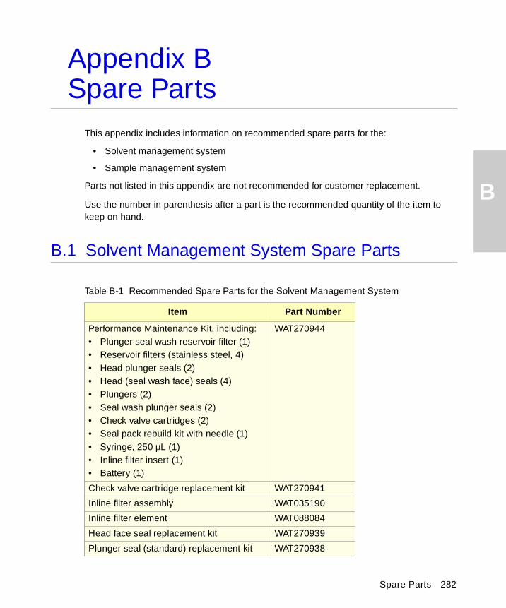
B
Appendix BSpare Parts
This appendix includes information on recommended spare parts for the:
• Solvent management system
• Sample management system
Parts not listed in this appendix are not recommended for customer replacement.
Use the number in parenthesis after a part is the recommended quantity of the item to keep on hand.
B.1 Solvent Management System Spare Parts
Table B-1 Recommended Spare Parts for the Solvent Management System
Item Part Number
Performance Maintenance Kit, including:• Plunger seal wash reservoir filter (1)• Reservoir filters (stainless steel, 4)• Head plunger seals (2)• Head (seal wash face) seals (4)• Plungers (2)• Seal wash plunger seals (2)• Check valve cartridges (2)• Seal pack rebuild kit with needle (1)• Syringe, 250 µL (1)• Inline filter insert (1)• Battery (1)
WAT270944
Check valve cartridge replacement kit WAT270941
Inline filter assembly WAT035190
Inline filter element WAT088084
Head face seal replacement kit WAT270939
Plunger seal (standard) replacement kit WAT270938
Spare Parts 282
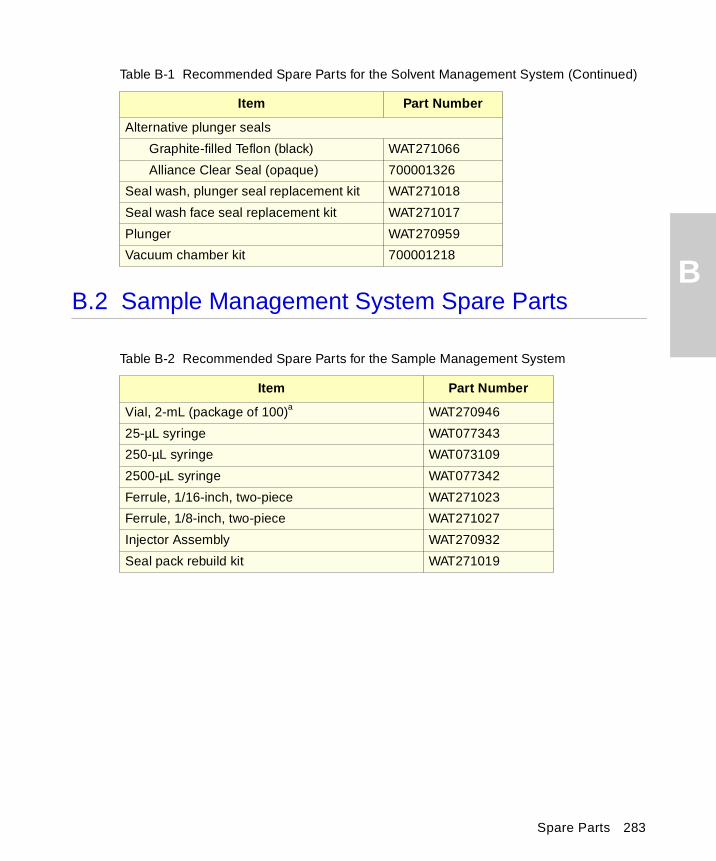
B
B.2 Sample Management System Spare PartsAlternative plunger seals
Graphite-filled Teflon (black) WAT271066
Alliance Clear Seal (opaque) 700001326
Seal wash, plunger seal replacement kit WAT271018
Seal wash face seal replacement kit WAT271017
Plunger WAT270959
Vacuum chamber kit 700001218
Table B-2 Recommended Spare Parts for the Sample Management System
Item Part Number
Vial, 2-mL (package of 100)a WAT270946
25-µL syringe WAT077343
250-µL syringe WAT073109
2500-µL syringe WAT077342
Ferrule, 1/16-inch, two-piece WAT271023
Ferrule, 1/8-inch, two-piece WAT271027
Injector Assembly WAT270932
Seal pack rebuild kit WAT271019
Table B-1 Recommended Spare Parts for the Solvent Management System (Continued)
Item Part Number
Spare Parts 283
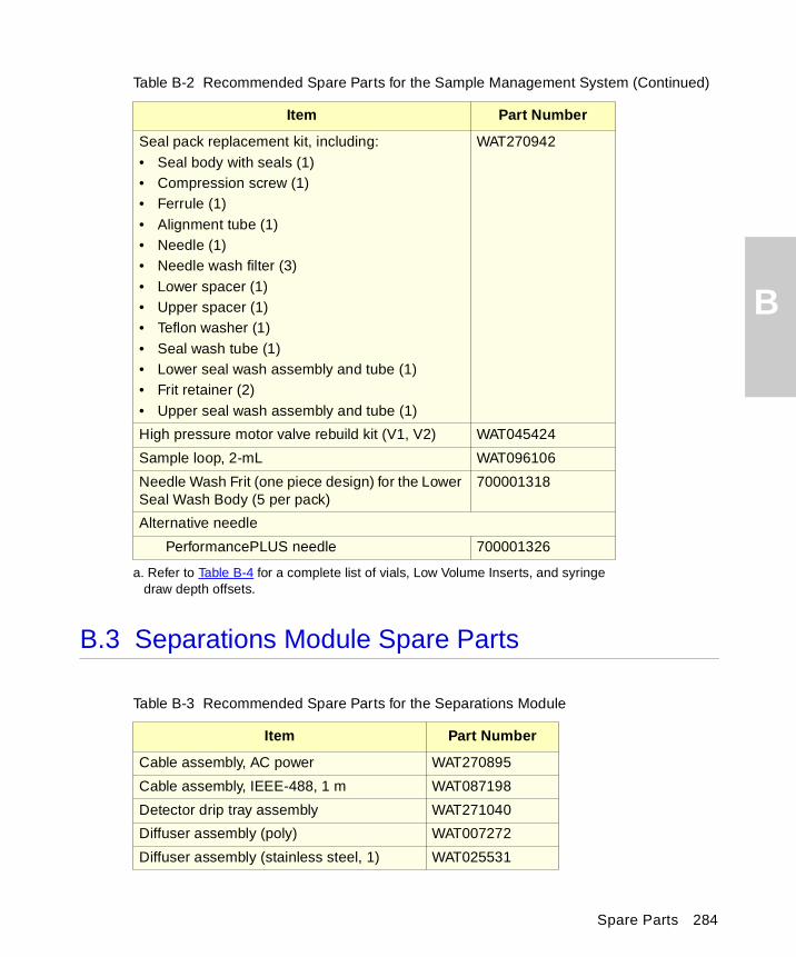
B
B.3 Separations Module Spare Parts
Seal pack replacement kit, including:• Seal body with seals (1)• Compression screw (1)• Ferrule (1)• Alignment tube (1)• Needle (1)• Needle wash filter (3)• Lower spacer (1)• Upper spacer (1)• Teflon washer (1)• Seal wash tube (1)• Lower seal wash assembly and tube (1)• Frit retainer (2)• Upper seal wash assembly and tube (1)
WAT270942
High pressure motor valve rebuild kit (V1, V2) WAT045424
Sample loop, 2-mL WAT096106
Needle Wash Frit (one piece design) for the Lower Seal Wash Body (5 per pack)
700001318
Alternative needle
PerformancePLUS needle 700001326
a. Refer to Table B-4 for a complete list of vials, Low Volume Inserts, and syringe draw depth offsets.
Table B-3 Recommended Spare Parts for the Separations Module
Item Part Number
Cable assembly, AC power WAT270895
Cable assembly, IEEE-488, 1 m WAT087198
Detector drip tray assembly WAT271040
Diffuser assembly (poly) WAT007272
Diffuser assembly (stainless steel, 1) WAT025531
Table B-2 Recommended Spare Parts for the Sample Management System (Continued)
Item Part Number
Spare Parts 284
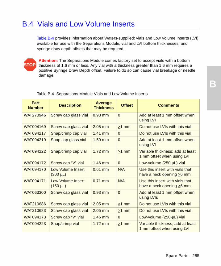
B
B.4 Vials and Low Volume Inserts
Table B-4 provides information about Waters-supplied: vials and Low Volume Inserts (LVI) available for use with the Separations Module, vial and LVI bottom thicknesses, and syringe draw depth offsets that may be required.
STOPAttention: The Separations Module comes factory set to accept vials with a bottom thickness of 1.6 mm or less. Any vial with a thickness greater than 1.6 mm requires a positive Syringe Draw Depth offset. Failure to do so can cause vial breakage or needle damage.
Table B-4 Separations Module Vials and Low Volume Inserts
Part Number
DescriptionAverage
ThicknessOffset Comments
WAT270946 Screw cap glass vial 0.93 mm 0 Add at least 1 mm offset when using LVI
WAT094169 Screw cap glass vial 2.05 mm >1 mm Do not use LVIs with this vial
WAT094217 Snap/crimp cap vial 1.41 mm 0 Do not use LVIs with this vial
WAT094219 Snap cap glass vial 1.59 mm 0 Add at least 1 mm offset when using LVI
WAT094222 Snap/crimp cap vial 1.72 mm >1 mm Variable thickness; add at least 1 mm offset when using LVI
WAT094172 Screw cap “V” vial 1.46 mm 0 Low-volume (250 µL) vial
WAT094170 Low Volume Insert (300 µL)
0.61 mm N/A Use this insert with vials that have a neck opening >6 mm
WAT094171 Low Volume Insert (150 µL)
0.71 mm N/A Use this insert with vials that have a neck opening >6 mm
WAT063300 Screw cap glass vial 0.93 mm 0 Add at least 1 mm offset when using LVIs
WAT210686 Screw cap glass vial 2.05 mm >1 mm Do not use LVIs with this vial
WAT210683 Screw cap glass vial 2.05 mm >1 mm Do not use LVIs with this vial
WAT094173 Screw cap “V” vial 1.46 mm 0 Low-volume (250-µL) vial
WAT094223 Snap/crimp vial 1.72 mm >1 mm Variable thickness; add at least 1 mm offset when using LVI
Spare Parts 285
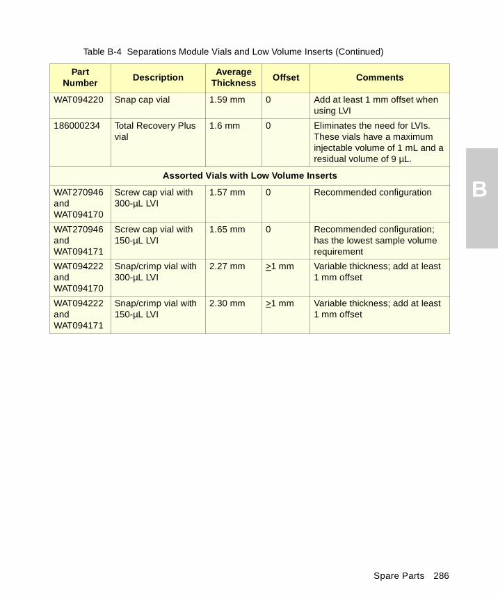
B
WAT094220 Snap cap vial 1.59 mm 0 Add at least 1 mm offset when using LVI
186000234 Total Recovery Plus vial
1.6 mm 0 Eliminates the need for LVIs. These vials have a maximum injectable volume of 1 mL and a residual volume of 9 µL.
Assorted Vials with Low Volume Inserts
WAT270946 and WAT094170
Screw cap vial with 300-µL LVI
1.57 mm 0 Recommended configuration
WAT270946 and WAT094171
Screw cap vial with 150-µL LVI
1.65 mm 0 Recommended configuration; has the lowest sample volume requirement
WAT094222 and WAT094170
Snap/crimp vial with 300-µL LVI
2.27 mm >1 mm Variable thickness; add at least 1 mm offset
WAT094222 and WAT094171
Snap/crimp vial with 150-µL LVI
2.30 mm >1 mm Variable thickness; add at least 1 mm offset
Table B-4 Separations Module Vials and Low Volume Inserts (Continued)
Part Number
DescriptionAverage
ThicknessOffset Comments
Spare Parts 286
C
Appendix CSolvent Considerations
C.1 Introduction
Clean Solvents
Clean solvents provide:
• Reproducible results
• Operation with minimal instrument maintenance
A dirty solvent can cause:
• Baseline noise and drift
• Blockage of the solvent filters with particulate matter
Solvent Quality
Use HPLC-grade solvents to ensure the best possible results. Filter solvents through 0.45-µm filters before use. Solvents distilled in glass generally maintain their purity from lot to lot; use them to ensure the best possible results.
Preparation Checklist
The following solvent preparation guidelines help to ensure stable baselines and good resolution:
• Filter solvents with a 0.45-µm filter.
• Degas and/or sparge the solvent.
• Stir the solvent.
• Keep solvents in a location that is free from drafts and shock.
Caution: To advoid chemical hazard, always observe safe laboratory practices with operating the system.
Solvent Considerations 287
C
Water
Use water only from a high-quality water purification system. If the water system does not provide filtered water, filter it through a 0.45-µm membrane filter before use.
Buffers
When you use buffers, dissolve salts first, adjust the pH, then filter to remove insoluble material.
Tetrahydrofuran (THF)
When using unstabilized THF, ensure that your solvent is fresh. Previously opened bottles of THF contain peroxide contaminants, which cause baseline drift.
C.2 Solvent Compatibility
The Waters 2695 Separations Module is constructed of high-quality (316) stainless steel components that, with some minor restrictions, can be used with all solvents. This section lists the solvents that have and have not been approved for use with the Separations Module.
Solvents to Avoid
The following solvents will attack or dissolve the Teflon AF tubing in the PerformancePLUS Inline degasser:
• All perfluorosolvents produced by 3M under the trade name Fluorinert™
• All perfluorosolvents produced by Ausimont under the trade names Galden™ and Fomblin™
Long-term static exposure to halide salts (for example, fluoride, bromide, chloride, and iodide) will cause pitting and corrosion of stainless steel parts. When using these salts, flush your system thoroughly with water if the pump will be idle for more than two days. Refer to Section 4.4.2, Performing a Wet Prime.
Caution: THF contaminants (peroxides) are potentially explosive if concentrated or taken to dryness.
Caution: Damage to the degassing tubing from exposure to perfluorosolvents is immediate and irreversible.
Solvent Considerations 288
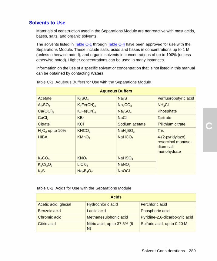
C
Solvents to Use
Materials of construction used in the Separations Module are nonreactive with most acids, bases, salts, and organic solvents.
The solvents listed in Table C-1 through Table C-4 have been approved for use with the Separations Module. These include salts, acids and bases in concentrations up to 1 M (unless otherwise noted), and organic solvents in concentrations of up to 100% (unless otherwise noted). Higher concentrations can be used in many instances.
Information on the use of a specific solvent or concentration that is not listed in this manual can be obtained by contacting Waters.
Table C-1 Aqueous Buffers for Use with the Separations Module
Aqueous Buffers
Acetate K2SO4 Na2S Perfluorobutyric acid
Al2SO4 K3Fe(CN)6 Na2CO3 NH4Cl
Ca(OCl)2 K4Fe(CN)6 Na2SO4 Phosphate
CaCl2 KBr NaCl Tartrate
Citrate KCl Sodium acetate Trilithium citrate
H2O2 up to 10% KHCO3 NaH2BO3 Tris
HIBA KMnO4 NaHCO3 4-(2-pyridylazo)resorcinol monoso-dium salt monohydrate
K2CO3 KNO3 NaHSO4
K2Cr2O3 LiCl04 NaNO3
K2S Na2B4O7 NaOCl
Table C-2 Acids for Use with the Separations Module
Acids
Acetic acid, glacial Hydrochloric acid Perchloric acid
Benzoic acid Lactic acid Phosphoric acid
Chromic acid Methanesulphonic acid Pyridine-2,6-dicarboxylic acid
Citric acid Nitric acid, up to 37.5% (6 N)
Sulfuric acid, up to 0.20 M
Solvent Considerations 289
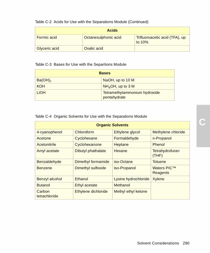
C
Formic acid Octanesulphonic acid Trifluoroacetic acid (TFA), up to 10%
Glyceric acid Oxalic acid
Table C-3 Bases for Use with the Separtions Module
Bases
Ba(OH)2 NaOH, up to 10 M
KOH NH4OH, up to 3 M
LiOH Tetramethylammonium hydroxide pentahydrate
Table C-4 Organic Solvents for Use with the Separations Module
Organic Solvents
4-cyanophenol Chloroform Ethylene glycol Methylene chloride
Acetone Cyclohexane Formaldehyde n-Propanol
Acetonitrile Cyclohexanone Heptane Phenol
Amyl acetate Dibutyl phathalate Hexane Tetrahydrofuran (THF)
Benzaldehyde Dimethyl formamide iso-Octane Toluene
Benzene Dimethyl sulfoxide iso-Propanol Waters PIC™ Reagents
Benzyl alcohol Ethanol Lysine hydrochloride Xylene
Butanol Ethyl acetate Methanol
Carbon tetrachloride
Ethylene dichloride Methyl ethyl ketone
Table C-2 Acids for Use with the Separations Module (Continued)
Acids
Solvent Considerations 290
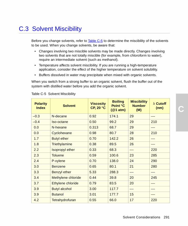
C
C.3 Solvent Miscibility
Before you change solvents, refer to Table C-5 to determine the miscibility of the solvents to be used. When you change solvents, be aware that:
• Changes involving two miscible solvents may be made directly. Changes involving two solvents that are not totally miscible (for example, from chloroform to water), require an intermediate solvent (such as methanol).
• Temperature affects solvent miscibility. If you are running a high-temperature application, consider the effect of the higher temperature on solvent solubility.
• Buffers dissolved in water may precipitate when mixed with organic solvents.
When you switch from a strong buffer to an organic solvent, flush the buffer out of the system with distilled water before you add the organic solvent.
Table C-5 Solvent Miscibility
Polarity Index
SolventViscosity CP, 20 °C
Boiling Point °C (@1 atm)
Miscibility Number
(M)
λ Cutoff (nm)
–0.3 N-decane 0.92 174.1 29 ––
–0.4 Iso-octane 0.50 99.2 29 210
0.0 N-hexane 0.313 68.7 29 ––
0.0 Cyclohexane 0.98 80.7 28 210
1.7 Butyl ether 0.70 142.2 26 ––
1.8 Triethylamine 0.38 89.5 26 ––
2.2 Isopropyl ether 0.33 68.3 –– 220
2.3 Toluene 0.59 100.6 23 285
2.4 P-xylene 0.70 138.0 24 290
3.0 Benzene 0.65 80.1 21 280
3.3 Benzyl ether 5.33 288.3 –– ––
3.4 Methylene chloride 0.44 39.8 20 245
3.7 Ethylene chloride 0.79 83.5 20 ––
3.9 Butyl alcohol 3.00 117.7 –– ––
3.9 Butanol 3.01 177.7 15 ––
4.2 Tetrahydrofuran 0.55 66.0 17 220
Solvent Considerations 291
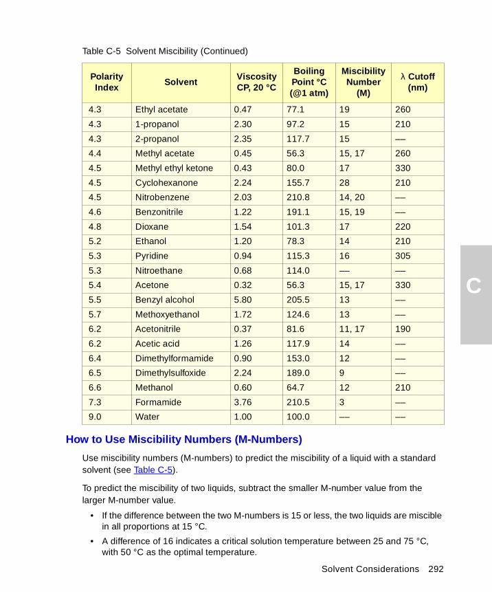
C
Solvent Considerations 292
How to Use Miscibility Numbers (M-Numbers)
Use miscibility numbers (M-numbers) to predict the miscibility of a liquid with a standard solvent (see Table C-5).
To predict the miscibility of two liquids, subtract the smaller M-number value from the larger M-number value.
• If the difference between the two M-numbers is 15 or less, the two liquids are miscible in all proportions at 15 °C.
• A difference of 16 indicates a critical solution temperature between 25 and 75 °C, with 50 °C as the optimal temperature.
4.3 Ethyl acetate 0.47 77.1 19 260
4.3 1-propanol 2.30 97.2 15 210
4.3 2-propanol 2.35 117.7 15 ––
4.4 Methyl acetate 0.45 56.3 15, 17 260
4.5 Methyl ethyl ketone 0.43 80.0 17 330
4.5 Cyclohexanone 2.24 155.7 28 210
4.5 Nitrobenzene 2.03 210.8 14, 20 ––
4.6 Benzonitrile 1.22 191.1 15, 19 ––
4.8 Dioxane 1.54 101.3 17 220
5.2 Ethanol 1.20 78.3 14 210
5.3 Pyridine 0.94 115.3 16 305
5.3 Nitroethane 0.68 114.0 –– ––
5.4 Acetone 0.32 56.3 15, 17 330
5.5 Benzyl alcohol 5.80 205.5 13 ––
5.7 Methoxyethanol 1.72 124.6 13 ––
6.2 Acetonitrile 0.37 81.6 11, 17 190
6.2 Acetic acid 1.26 117.9 14 ––
6.4 Dimethylformamide 0.90 153.0 12 ––
6.5 Dimethylsulfoxide 2.24 189.0 9 ––
6.6 Methanol 0.60 64.7 12 210
7.3 Formamide 3.76 210.5 3 ––
9.0 Water 1.00 100.0 –– ––
Table C-5 Solvent Miscibility (Continued)
Polarity Index
SolventViscosity CP, 20 °C
Boiling Point °C (@1 atm)
Miscibility Number
(M)
λ Cutoff (nm)
C
• If the difference is 17 or greater, the liquids are immiscible or their critical solution temperature is above 75 °C.
Some solvents prove immiscible with solvents at both ends of the lipophilicity scale. These solvents receive a dual M-number:
• The first number, always lower than 16, indicates the degree of miscibility with highly lipophilic solvents.
• The second number applies to the opposite end of the scale. A large difference between these two numbers indicates a limited range of miscibility.
For example, some fluorocarbons are immiscible with all the standard solvents and have M-numbers of 0 and 32. Two liquids with dual M-numbers are usually miscible with each other.
A liquid is classified in the M-number system by testing for miscibility with a sequence of standard solvents. A correction term of 15 units is then either added or subtracted from the cutoff point for miscibility.
C.4 Buffered Solvents
When using a buffer, use a good quality reagent and filter it through a 0.45-µm filter.
Do not leave the buffer stored in the system after use. Flush all fluidic pathways with HPLC-quality water before shutting down the system and leave distilled water in the system (flush with 90% HPLC-quality water:10% methanol for shutdowns scheduled to be more than one day). Flush using a minimum of 15 mL for sparge-equipped units, and a minimum of 45 mL for inline vacuum degasser-equipped units.
C.5 Head Height
Position the solvent reservoirs at a level above the Separations Module or on top of the Separations Module (with adequate spill protection).
C.6 Solvent Viscosity
Generally, viscosity is not important when you are operating with a single solvent or under low pressure. However when you are running a gradient, the viscosity changes that occur as the solvents are mixed in different proportions can result in pressure changes during the run. For example, a 1:1 mixture of water and methanol produces twice the pressure of either water or methanol alone.
Solvent Considerations 293

C
If the extent to which the pressure changes affect the analysis is not known, monitor the pressure during the run using the Chart Out terminal.
C.7 Mobile Phase Solvent Degassing
Mobile phase difficulties account for 70% or more of all liquid chromatographic problems. Using degassed solvents is important, especially at wavelengths below 220 nm. Degassing provides:
• Stable baselines and enhanced sensitivity
• Reproducible retention times for eluting peaks
• Reproducible injection volumes for quantitation
• Stable pump operation
This section presents information on the solubility of gases, solvent degassing methods, and solvent degassing considerations.
C.7.1 Gas Solubility
Only a finite amount of gas can be dissolved in a given volume of liquid. This amount depends on:
• The chemical affinity of the gas for the liquid.
• The temperature of the liquid.
• The pressure applied to the liquid.
Changes in the composition, temperature, or pressure of the mobile phase can lead to outgassing.
Effects of Intermolecular Forces
Nonpolar gases (N2, O2, CO2, He) are more soluble in nonpolar solvents than in polar solvents. Generally, a gas is most soluble in a solvent whose intermolecular attractive forces are similar to those in the gas ("like dissolves like").
Effects of Temperature
Temperature affects the solubility of gases. If the heat of solution is exothermic, the solubility of the gas decreases when you heat the solvent. If the heat of solution is endothermic, the solubility increases when you heat the solvent. For example, the solubility of He in H2O decreases with an increase in temperature, but the solubility of He in benzene increases with an increase in temperature.
Solvent Considerations 294
C
Effects of Partial Pressure
The mass of gas dissolved in a given volume of solvent is proportional to the partial pressure of the gas in the vapor phase of the solvent. If you decrease the partial pressure of the gas, the amount of that gas in solution also decreases.
C.7.2 Solvent Degassing Methods
You can degas solvents by either of the following methods:
• Sparging with helium
• Vacuum degassing
Sparging
Sparging removes gases from solution by displacing dissolved gases in the solvent with a less soluble gas, usually helium. Well-sparged solvent improves pump performance. Helium sparging brings the solvent to a state of equilibrium, which may be maintained by slow sparging or by keeping a blanket of helium over the solvent. Blanketing inhibits reabsorption of atmospheric gases.
Note: Sparging may change the composition of mixed solvents.
Vacuum Degassing
The inline vacuum degasser operates on the principle of Henry’s Law to remove dissolved gases from the solvent. According to Henry’s Law, the mole fraction of a gas dissolved in a liquid is proportional to the partial pressure of that gas in the vapor phase above the liquid. If the partial pressure of a gas on the surface of the liquid is reduced, for example, by evacuation, then a proportional amount of that gas comes out of solution. Refer to the Vacuum Degassing discussion below and to the “PerformancePLUS Inline Degasser” discussion in Section 1.5.
Note: Vacuum degassing may change the composition of mixed solvents.
C.7.3 Solvent Degassing Considerations
Select the most efficient degassing operation for your application. To remove dissolved gas quickly, consider the following.
Sparging
Helium sparging gives stable baselines and better detection sensitivity than sonication, and prevents reabsorption of atmospheric gases. Use this method to retard oxidation when you are using THF or other peroxide-forming solvents.
Solvent Considerations 295
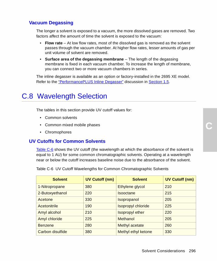
C
Vacuum Degassing
The longer a solvent is exposed to a vacuum, the more dissolved gases are removed. Two factors affect the amount of time the solvent is exposed to the vacuum:
• Flow rate – At low flow rates, most of the dissolved gas is removed as the solvent passes through the vacuum chamber. At higher flow rates, lesser amounts of gas per unit volume of solvent are removed.
• Surface area of the degassing membrane – The length of the degassing membrane is fixed in each vacuum chamber. To increase the length of membrane, you can connect two or more vacuum chambers in series.
The inline degasser is available as an option or factory-installed in the 2695 XE model. Refer to the “PerformancePLUS Inline Degasser” discussion in Section 1.5.
C.8 Wavelength Selection
The tables in this section provide UV cutoff values for:
• Common solvents
• Common mixed mobile phases
• Chromophores
UV Cutoffs for Common Solvents
Table C-6 shows the UV cutoff (the wavelength at which the absorbance of the solvent is equal to 1 AU) for some common chromatographic solvents. Operating at a wavelength near or below the cutoff increases baseline noise due to the absorbance of the solvent.
Table C-6 UV Cutoff Wavelengths for Common Chromatographic Solvents
Solvent UV Cutoff (nm) Solvent UV Cutoff (nm)
1-Nitropropane 380 Ethylene glycol 210
2-Butoxyethanol 220 Isooctane 215
Acetone 330 Isopropanol 205
Acetonitrile 190 Isopropyl chloride 225
Amyl alcohol 210 Isopropyl ether 220
Amyl chloride 225 Methanol 205
Benzene 280 Methyl acetate 260
Carbon disulfide 380 Methyl ethyl ketone 330
Solvent Considerations 296
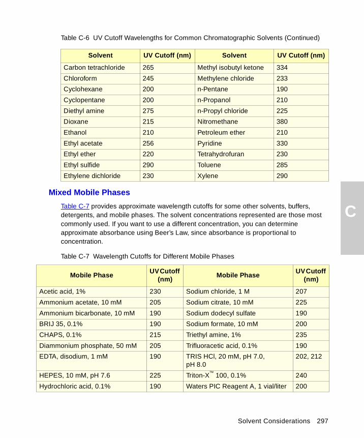
C
Mixed Mobile PhasesTable C-7 provides approximate wavelength cutoffs for some other solvents, buffers, detergents, and mobile phases. The solvent concentrations represented are those most commonly used. If you want to use a different concentration, you can determine approximate absorbance using Beer’s Law, since absorbance is proportional to concentration.
Carbon tetrachloride 265 Methyl isobutyl ketone 334
Chloroform 245 Methylene chloride 233
Cyclohexane 200 n-Pentane 190
Cyclopentane 200 n-Propanol 210
Diethyl amine 275 n-Propyl chloride 225
Dioxane 215 Nitromethane 380
Ethanol 210 Petroleum ether 210
Ethyl acetate 256 Pyridine 330
Ethyl ether 220 Tetrahydrofuran 230
Ethyl sulfide 290 Toluene 285
Ethylene dichloride 230 Xylene 290
Table C-7 Wavelength Cutoffs for Different Mobile Phases
Mobile PhaseUV Cutoff
(nm)Mobile Phase
UV Cutoff (nm)
Acetic acid, 1% 230 Sodium chloride, 1 M 207
Ammonium acetate, 10 mM 205 Sodium citrate, 10 mM 225
Ammonium bicarbonate, 10 mM 190 Sodium dodecyl sulfate 190
BRIJ 35, 0.1% 190 Sodium formate, 10 mM 200
CHAPS, 0.1% 215 Triethyl amine, 1% 235
Diammonium phosphate, 50 mM 205 Trifluoracetic acid, 0.1% 190
EDTA, disodium, 1 mM 190 TRIS HCl, 20 mM, pH 7.0, pH 8.0
202, 212
HEPES, 10 mM, pH 7.6 225 Triton-X™ 100, 0.1% 240
Hydrochloric acid, 0.1% 190 Waters PIC Reagent A, 1 vial/liter 200
Table C-6 UV Cutoff Wavelengths for Common Chromatographic Solvents (Continued)
Solvent UV Cutoff (nm) Solvent UV Cutoff (nm)
Solvent Considerations 297
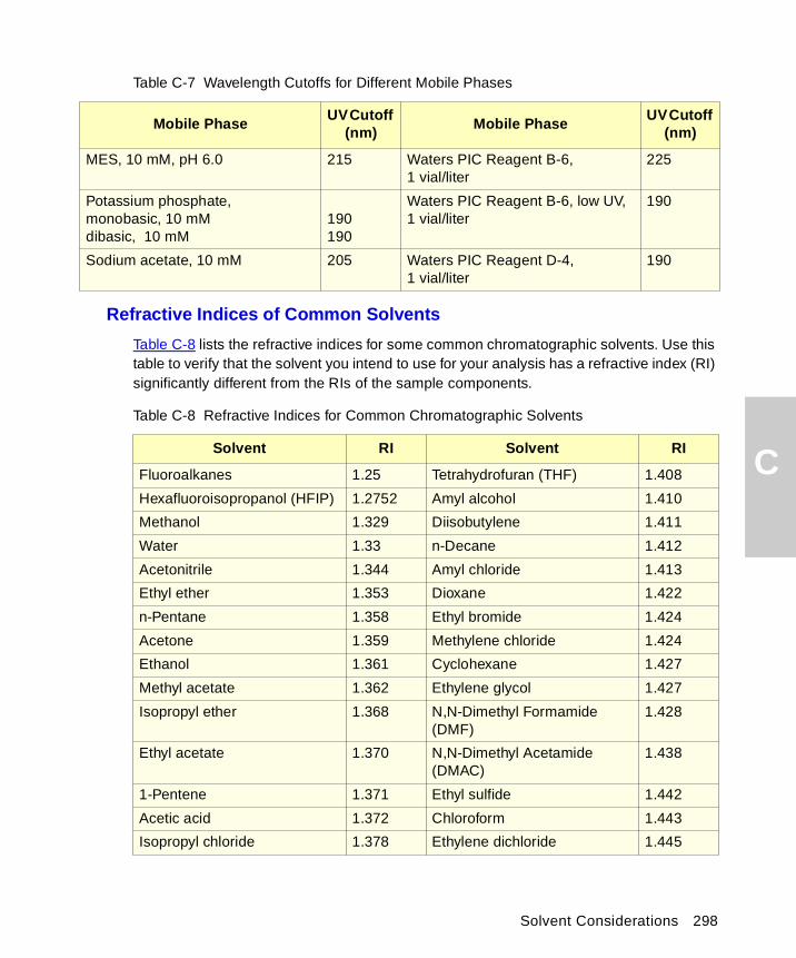
C
Refractive Indices of Common Solvents
Table C-8 lists the refractive indices for some common chromatographic solvents. Use this table to verify that the solvent you intend to use for your analysis has a refractive index (RI) significantly different from the RIs of the sample components.
MES, 10 mM, pH 6.0 215 Waters PIC Reagent B-6, 1 vial/liter
225
Potassium phosphate, monobasic, 10 mM dibasic, 10 mM
190190
Waters PIC Reagent B-6, low UV, 1 vial/liter
190
Sodium acetate, 10 mM 205 Waters PIC Reagent D-4, 1 vial/liter
190
Table C-8 Refractive Indices for Common Chromatographic Solvents
Solvent RI Solvent RI
Fluoroalkanes 1.25 Tetrahydrofuran (THF) 1.408
Hexafluoroisopropanol (HFIP) 1.2752 Amyl alcohol 1.410
Methanol 1.329 Diisobutylene 1.411
Water 1.33 n-Decane 1.412
Acetonitrile 1.344 Amyl chloride 1.413
Ethyl ether 1.353 Dioxane 1.422
n-Pentane 1.358 Ethyl bromide 1.424
Acetone 1.359 Methylene chloride 1.424
Ethanol 1.361 Cyclohexane 1.427
Methyl acetate 1.362 Ethylene glycol 1.427
Isopropyl ether 1.368 N,N-Dimethyl Formamide (DMF)
1.428
Ethyl acetate 1.370 N,N-Dimethyl Acetamide (DMAC)
1.438
1-Pentene 1.371 Ethyl sulfide 1.442
Acetic acid 1.372 Chloroform 1.443
Isopropyl chloride 1.378 Ethylene dichloride 1.445
Table C-7 Wavelength Cutoffs for Different Mobile Phases
Mobile PhaseUV Cutoff
(nm)Mobile Phase
UV Cutoff (nm)
Solvent Considerations 298
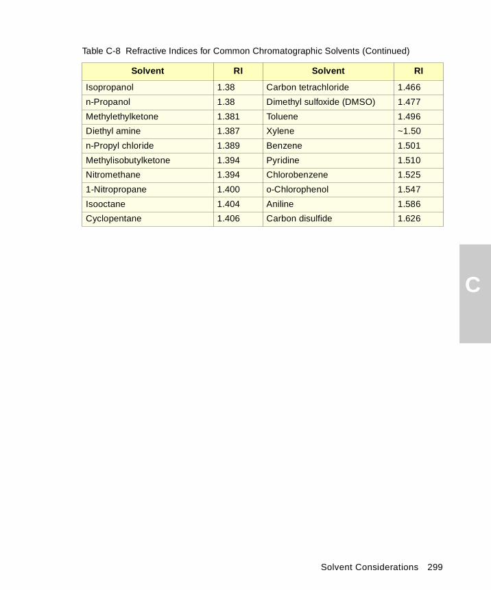
C
Isopropanol 1.38 Carbon tetrachloride 1.466
n-Propanol 1.38 Dimethyl sulfoxide (DMSO) 1.477
Methylethylketone 1.381 Toluene 1.496
Diethyl amine 1.387 Xylene ~1.50
n-Propyl chloride 1.389 Benzene 1.501
Methylisobutylketone 1.394 Pyridine 1.510
Nitromethane 1.394 Chlorobenzene 1.525
1-Nitropropane 1.400 o-Chlorophenol 1.547
Isooctane 1.404 Aniline 1.586
Cyclopentane 1.406 Carbon disulfide 1.626
Table C-8 Refractive Indices for Common Chromatographic Solvents (Continued)
Solvent RI Solvent RI
Solvent Considerations 299
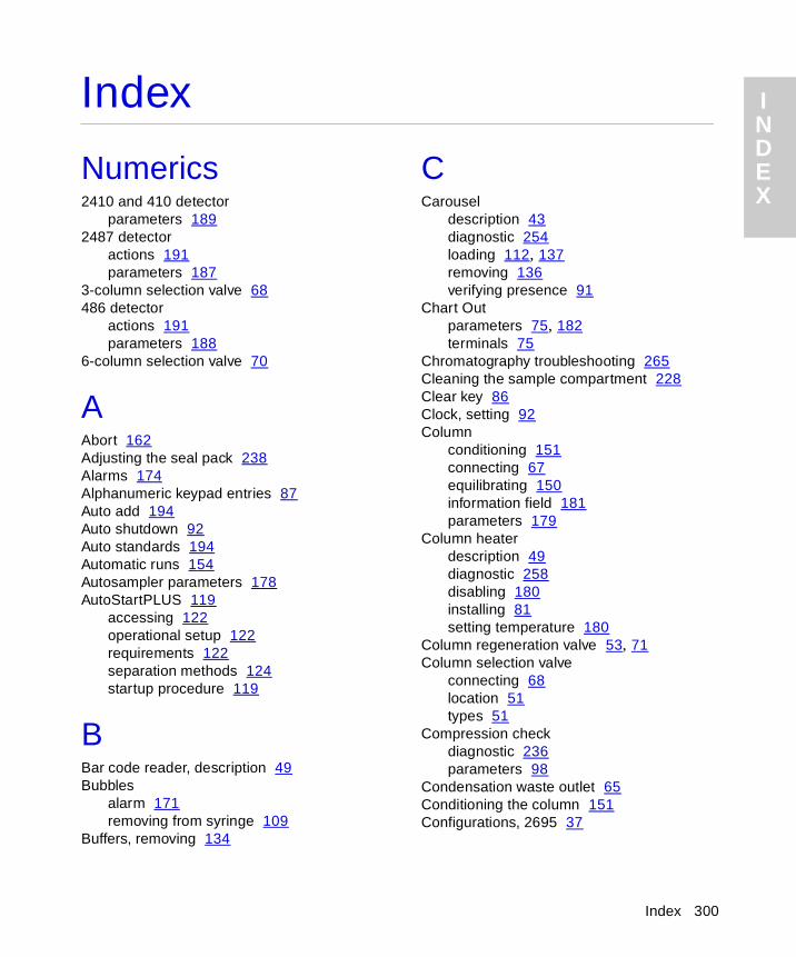
I NDEX
Index
Numerics2410 and 410 detector
parameters 1892487 detector
actions 191parameters 187
3-column selection valve 68486 detector
actions 191parameters 188
6-column selection valve 70
AAbort 162Adjusting the seal pack 238Alarms 174Alphanumeric keypad entries 87Auto add 194Auto shutdown 92Auto standards 194Automatic runs 154Autosampler parameters 178AutoStartPLUS 119
accessing 122operational setup 122requirements 122separation methods 124startup procedure 119
BBar code reader, description 49Bubbles
alarm 171removing from syringe 109
Buffers, removing 134
CCarousel
description 43diagnostic 254loading 112, 137removing 136verifying presence 91
Chart Outparameters 75, 182terminals 75
Chromatography troubleshooting 265Cleaning the sample compartment 228Clear key 86Clock, setting 92Column
conditioning 151connecting 67equilibrating 150information field 181parameters 179
Column heaterdescription 49diagnostic 258disabling 180installing 81setting temperature 180
Column regeneration valve 53, 71Column selection valve
connecting 68location 51types 51
Compression checkdiagnostic 236parameters 98
Condensation waste outlet 65Conditioning the column 151Configurations, 2695 37
Index 300
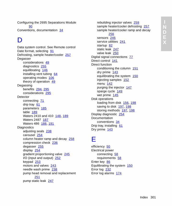
INDEX
Configuring the 2695 Separations Module 90
Conventions, documentation 34
DData system control. See Remote controlDate format, selecting 91Defrosting, sample heater/cooler 257Degasser
considerations 49diagnostics 255equilibrating 146installing vent tubing 64operating modes 106theory of operation 49
Degassingbenefits 294, 295considerations 295
Detectorconnecting 71drip tray 61parameters 185table 189Waters 2410 and 410 148, 189Waters 2487 187Waters 486 188, 191
Diagnosticsadjusting seals 238carousel 254column heater ramp and decay 258compression check 236degasser 255display 254gradient proportioning valve 245I/O (input and output) 252keypad 253motors and valves 243needle wash prime 238pump head removal and replacement
251pump static leak 247
I
rebuilding injector valves 259sample heater/cooler defrosting 257sample heater/cooler ramp and decay
256sensors 246service utilities 241startup 82static leak 247valve leak 250
Digital signal connections 77Direct control 141Direct function
conditioning the column 151dry prime 143equilibrating the system 150injecting samples 152menu 142purging the injector 147sparge cycle 149wet prime 145
Disk operationsloading from disk 156, 198saving to disk 197, 198storing methods 197, 198
Display diagnostic 254Documentation
conventions 34Drip tray, installing 61Dry prime 143
Eefficiency 50Electrical power
connecting 58requirements 58
Enter key 86Equilibrating the system 150Error log 232Error log alarms 174
Index 301

INDEX
Event switchesdescription 76initial state 182
Events in, defining 93Exporting methods 197, 198
FFile
loading from disk 156, 198saving to disk 197, 198
Flow pathsample management system 42solvent management system 39
Flow rate ramp 172Fluidic connections 59Front panel control 141Functional view, sample set 158Functions
direct 142sample set 193
GGas solubility 294Gradient proportioning valve diagnostic 245Gradient table 174
HHardware options 78Heater/cooler
disabling 177setting temperature 177
Helium specifications 106Help key 86Hold Inject terminals 75
I
II/O
connectors 74diagnostic test 252event switches 76parameters 181signals 74timed table 183
I/O Events table 183IEEE-488 interface
address 78connections 78scanning 91
Importing methods 198Inject start terminal 74Injecting
auto add 194auto standards 194from the front panel 152samples 152
Injection view, sample set 158Injector
purging 147, 222reinstalling 227removing 223, 225
Injector valves, rebuilding 259Inline filter, replacing 213Installation
3-column selection valve 686-column selection valve 70column regeneration valve 71
Installation site requirements 55
KKeypad
alphanumeric entries 87diagnostic 253functions 85
Index 302
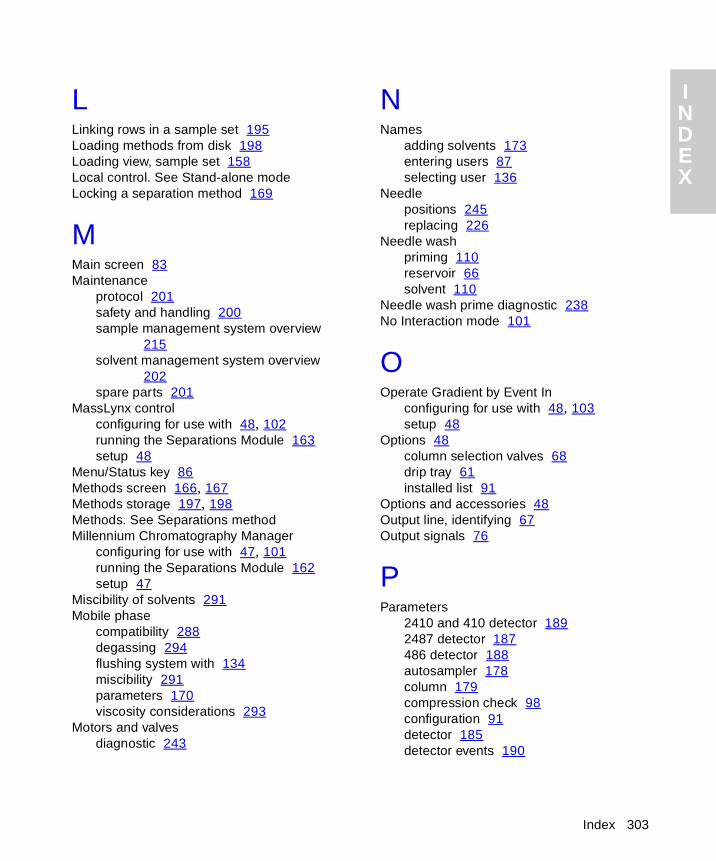
INDEX
LLinking rows in a sample set 195Loading methods from disk 198Loading view, sample set 158Local control. See Stand-alone modeLocking a separation method 169
MMain screen 83Maintenance
protocol 201safety and handling 200sample management system overview
215solvent management system overview
202spare parts 201
MassLynx controlconfiguring for use with 48, 102running the Separations Module 163setup 48
Menu/Status key 86Methods screen 166, 167Methods storage 197, 198Methods. See Separations methodMillennium Chromatography Manager
configuring for use with 47, 101running the Separations Module 162setup 47
Miscibility of solvents 291Mobile phase
compatibility 288degassing 294flushing system with 134miscibility 291parameters 170viscosity considerations 293
Motors and valvesdiagnostic 243
I
NNames
adding solvents 173entering users 87selecting user 136
Needlepositions 245replacing 226
Needle washpriming 110reservoir 66solvent 110
Needle wash prime diagnostic 238No Interaction mode 101
OOperate Gradient by Event In
configuring for use with 48, 103setup 48
Options 48column selection valves 68drip tray 61installed list 91
Options and accessories 48Output line, identifying 67Output signals 76
PParameters
2410 and 410 detector 1892487 detector 187486 detector 188autosampler 178column 179compression check 98configuration 91detector 185detector events 190
Index 303
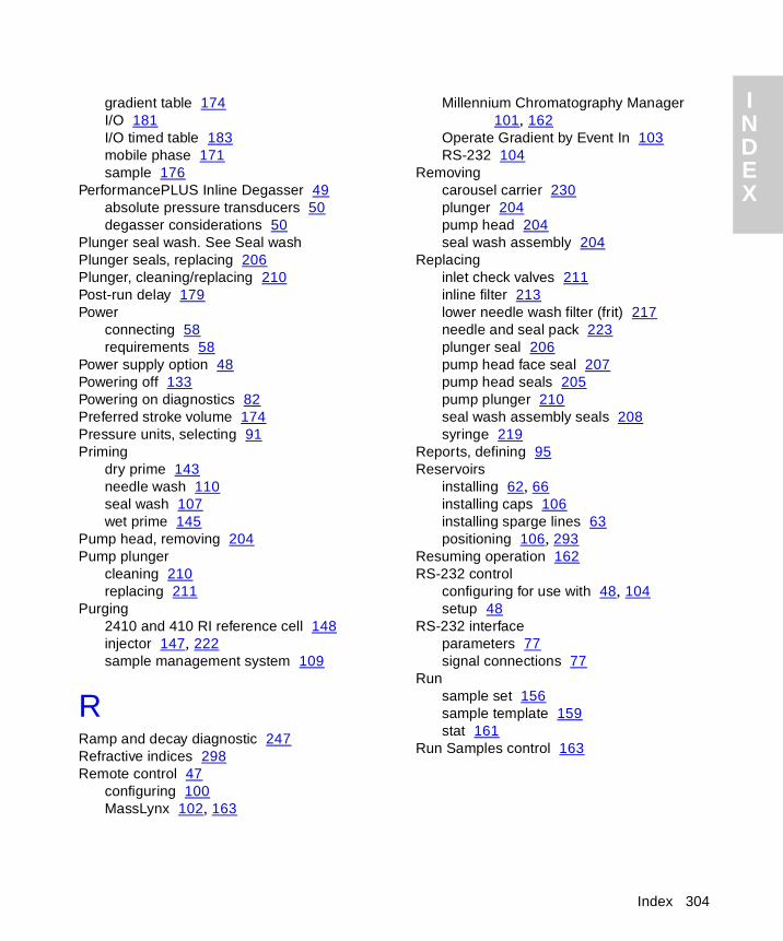
INDEX
gradient table 174I/O 181I/O timed table 183mobile phase 171sample 176
PerformancePLUS Inline Degasser 49absolute pressure transducers 50degasser considerations 50
Plunger seal wash. See Seal washPlunger seals, replacing 206Plunger, cleaning/replacing 210Post-run delay 179Power
connecting 58requirements 58
Power supply option 48Powering off 133Powering on diagnostics 82Preferred stroke volume 174Pressure units, selecting 91Priming
dry prime 143needle wash 110seal wash 107wet prime 145
Pump head, removing 204Pump plunger
cleaning 210replacing 211
Purging2410 and 410 RI reference cell 148injector 147, 222sample management system 109
RRamp and decay diagnostic 247Refractive indices 298Remote control 47
configuring 100MassLynx 102, 163
I
Millennium Chromatography Manager 101, 162
Operate Gradient by Event In 103RS-232 104
Removingcarousel carrier 230plunger 204pump head 204seal wash assembly 204
Replacinginlet check valves 211inline filter 213lower needle wash filter (frit) 217needle and seal pack 223plunger seal 206pump head face seal 207pump head seals 205pump plunger 210seal wash assembly seals 208syringe 219
Reports, defining 95Reservoirs
installing 62, 66installing caps 106installing sparge lines 63positioning 106, 293
Resuming operation 162RS-232 control
configuring for use with 48, 104setup 48
RS-232 interfaceparameters 77signal connections 77
Runsample set 156sample template 159stat 161
Run Samples control 163
Index 304
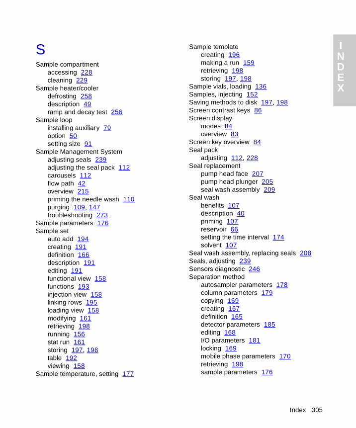
INDEX
SSample compartment
accessing 228cleaning 229
Sample heater/coolerdefrosting 258description 49ramp and decay test 256
Sample loopinstalling auxiliary 79option 50setting size 91
Sample Management Systemadjusting seals 239adjusting the seal pack 112carousels 112flow path 42overview 215priming the needle wash 110purging 109, 147troubleshooting 273
Sample parameters 176Sample set
auto add 194creating 191definition 166description 191editing 191functional view 158functions 193injection view 158linking rows 195loading view 158modifying 161retrieving 198running 156stat run 161storing 197, 198table 192viewing 158
Sample temperature, setting 177
I
Sample templatecreating 196making a run 159retrieving 198storing 197, 198
Sample vials, loading 136Samples, injecting 152Saving methods to disk 197, 198Screen contrast keys 86Screen display
modes 84overview 83
Screen key overview 84Seal pack
adjusting 112, 228Seal replacement
pump head face 207pump head plunger 205seal wash assembly 209
Seal washbenefits 107description 40priming 107reservoir 66setting the time interval 174solvent 107
Seal wash assembly, replacing seals 208Seals, adjusting 239Sensors diagnostic 246Separation method
autosampler parameters 178column parameters 179copying 169creating 167definition 165detector parameters 185editing 168I/O parameters 181locking 169mobile phase parameters 170retrieving 198sample parameters 176
Index 305
INDEX
storing 197, 198unlocking 169
Serial number, location 43Service utilities 241Set clock 92Shutdown
automatic 92powering off 134
Side panelinstalling 81removing 79
Signal connectionsI/O 73IEEE-488 78RS-232 77
Site requirements 55Software, updating 230Solvent
adding names 173buffered solvents 134, 293compatibility 288general considerations 287guidelines 287installing reservoirs 62, 66miscibility 291refractive indices 298removing buffers 134tubing identification 62UV cutoff 296vacuum degassing 50viscosity considerations 293
Solvent Management Systemflow path 39flow rate ramp 172head removal 251overview 203preparing 105priming 107, 143, 145static leak diagnostic 247troubleshooting 271
Solvent reservoirs. See Reservoirs
I
Spare partssample management system 283, 284solvent management system 282
Spargebenefits 106description 106helium specifications 63installing reservoir lines 63making connections 62overview 106, 295programming sparge cycle 149setting flow rates 149setting initial time 149
Specificationselectrical 277instrument control and communication
280physical 276sample management system 279solvent management system 278
Spill tray waste outlet 65Stand-alone mode 45Startup
AutoStartPLUS startup procedure 119diagnostic 82routine 135
Stat run 161Status screens 137Stop flow
key 86programming terminals 94terminals 74
Stopping a run 161Stroke volume 174Syringe
configuring 221description 43draw depth 178draw rate 177positions 245
Index 306
INDEX
removal and replacement 219removing air bubbles 109setting size 91, 221
System Controller mode 101System monitoring 137
TThree-column selection valve
connections 68description 52
Time and date, setting 92Timed table, I/O 183Troubleshooting
basic 263chromatography 264hardware 269sample management system 273solvent management system 271
UUnlocking a separation method 169Unpacking the Separations Module 57Updating software 230User name
entering 87selecting 136
VValve description 41Valve leak diagnostic 250Valves
3-column selection 686-column selection 70column regeneration 71column selection 68
Valves and motors diagnostic 243Vent tubing, installing 64
I
Verifyingcarousel placement 91vial presence 91
Vialloading 136range 153separating multiple entries 192specifications 137verifying presence 91
Views, sample setfunctional 158injection 158loading 158
WWaste line connections
condensation waste 65spill tray 65
Waters 2410 and 410 RI detectorparameters 189purging reference cell 148
Waters 2487 detectoractions 191parameters 187
Waters 486 detectoractions 191parameters 188
Waters Technical Service, contacting 202, 264
Wavelength selection 296Wet prime 145
Index 307