270249 service manual - Новости transistor packages to92 to126 to220 to3p bc547, bc557:...
TRANSCRIPT

1
Index
Soldering point.
Male connector.
Female connector.
M/F faston connector.
Test point.Supply voltage. Logic supply ground.
Analog supply ground.
Chassis ground.
Earth ground.
Flag joined with one or more flags
GENERALMUSIC S.p.A. Sales Division: 47842 S.Giovanni in Marignano (RN) ITALY - Via delle Rose, 12
Phone +39(0)541/959511 - Fax +39(0)541/957404 - GENERALMUSIC on the NET: http://www.generalmusic.com
Technical Specifications, Transistors Packages2
Passive Version Schematics3
Active Version Block Diagrams
5
PFM15SA Schematic
6 Test Procedures and Adjustments, PFM15.2A
7
Test Procedures and Adjustments, PFM10.2A-PFM8MA, PFM12.2A-PFM12.2MA
8 Test Procedures and Adjustments, PFM15SA, Advices
9
PFM10.2A-PFM8MA, PFM12.2A-PFM12.2MA Schematic10
PFM15.2A-PFM15.2MA Schematic11
12
Test Procedures and Adjustments, PFM15.3A
13
14
Reliability and Burn In Checks, F igures
4
Spare Part List
PFM15.3A Schematic
SERVICE MANUAL
CODE: 270249
Warnings
with the same signal name inscribed.
AddressATTENTION Observe
precautions when handling electrostatic sensitive devices.
NoticeService must be carried out by qualified personnel only. Any tampering carried out by unqualified personnel during the guarantee period
will forfeit the right to guarantee.
For a correct operation of the instrument, after having switched off, be careful to wait at least 3 seconds before switching on again.
To improve the device's specifications, the schematic diagrams may be subject to change without prior notice.
All components marked by this symbol have special safety characteristics, when replacing any of these components use only
manufacturer's specified parts.
The (µ) micro symbol of capacitance value is substituted by U.
The (Ω) omega symbol of resistance value is substituted by E.
The electrolytic capacitors are 25Vdc rated voltage unless otherwise specified.
All resistors are 1/8W unless otherwise specified.
All switches shown in the "OFF" position. All DC voltages measured to ground with a voltmeter 20KOhm/V.

2
Transistor PackagesTO92TO92TO92TO92TO92 TO126TO126TO126TO126TO126 TO220TO220TO220TO220TO220 TO3PTO3PTO3PTO3PTO3P
BC547, BC557:BC547, BC557:BC547, BC557:BC547, BC557:BC547, BC557: MJE340, MJE350,MJE340, MJE350,MJE340, MJE350,MJE340, MJE350,MJE340, MJE350, TIP41C, TIP42C:TIP41C, TIP42C:TIP41C, TIP42C:TIP41C, TIP42C:TIP41C, TIP42C: 2SC3284, 2SA1303:2SC3284, 2SA1303:2SC3284, 2SA1303:2SC3284, 2SA1303:2SC3284, 2SA1303:
1=Collector MJE802:MJE802:MJE802:MJE802:MJE802: 1=Base 1=Base
2=Base 1=Emitter 2=Collector 2=Collector
3=Emitter 2=Collector 3=Emitter 3=Emitter
2N5401, 2N55502N5401, 2N55502N5401, 2N55502N5401, 2N55502N5401, 2N5550 3=Base 4=Collector 4=Collector
1=Emitter 4=Collector
2=Base
3=Collector
!
!"#$
%&'()('*
"
+ + +
#$% + + +
""
&'()*+&, (
"-
"
,
-.
/)'01)
23/456'7
!"#$(285,%*
!"#$(2859%'*
"-
-&#&* + + + + + + + +
.$ !%!/ / + +
.' + +
01"- !
+ " + + + + + + + +
!"#!$
%&
'
:%;<(=>*
%/*
%.)*%'.)*
0).)1&&'>
=.'1 1&)7.&1
/)'01)
285,(!"#$%&'()*
!"#$%&'()*
#1&.? 1.)'&

3

4

5
TEST PROCEDURES & ADJUSTMENTSThese procedures are relative to the ACTIVE versions (amplifiedloudspeakers) only.
Precaution To prevent short circuit during any test, the oscilloscope must bethe oscilloscope must bethe oscilloscope must bethe oscilloscope must bethe oscilloscope must be
EARTH insulatedEARTH insulatedEARTH insulatedEARTH insulatedEARTH insulated, this occurs because some test require to connectits probe to the amplifier output, non-compliance may cause dam-ages to oscilloscope inputs circuitry.
Before removing or installing any modules and connectors, discon-discon-discon-discon-discon-nect the amplifier from AC MAINSnect the amplifier from AC MAINSnect the amplifier from AC MAINSnect the amplifier from AC MAINSnect the amplifier from AC MAINS and measure the DC supplyvoltages across each of the power suppliy capacitors. If yourmeasurement on any of the caps is greater than 10Vdc, connect a100Ω 10W resistor across the applicable caps to discharge them foryour safety. Remember to remove the discharge resistor immediatelyafter discharging caps. Do not power up the amplifier with theDo not power up the amplifier with theDo not power up the amplifier with theDo not power up the amplifier with theDo not power up the amplifier with thedischarge resistor connecteddischarge resistor connecteddischarge resistor connecteddischarge resistor connecteddischarge resistor connected.
Read these notes entirely before proceeding to any operation. Thesenotes are not comprehensive of all damages that possibly occur, butincludes some specifically advices, checks and adjustments relativeto this amplified speaker.
Do not check the amplifier with the speaker connected use only anDo not check the amplifier with the speaker connected use only anDo not check the amplifier with the speaker connected use only anDo not check the amplifier with the speaker connected use only anDo not check the amplifier with the speaker connected use only anappropriate load resistor.appropriate load resistor.appropriate load resistor.appropriate load resistor.appropriate load resistor.
Visual Check Check the speakers for any damaging (cone-breaking, interruption or
so).
Before proceed to supply the amplifier check visually the internalassembly, if appears an evident damage find the most possiblereasons that cause it.
Check the wiring cables for possible interruptions or shorts.
If the damage has burnt a printed circuit board don’t try to repair it,replace with a new one.
Test Instruments Audio Generator
Dual Trace Oscilloscope
Digital Multimeter
Temperature Meter
8Ω 500W, 4Ω 500W, 100Ω 10W resistors
Variac (0÷250Vac)
PFM10.2A-PFM8MA Amplified LoudspeakerThe following adjustment and notes are relative to these models only.
Technical SpecificationsDimensions: PFM10.2A (WxHxD) 340x458x285mm
Dimensions: PFM8MA (WxHxD) 305x395x275mm
Weight: PFM10.2A 12Kg
Weight: PFM8MA 11.5Kg
Power Requirements: (230Vac±10% 50Hz) 150VA
(115Vac±10% 50/60Hz) 150VA
Output Power*: (8Ω) 90W
Max.Undistorted Out*: (8Ω) 76Vpp
Sensitivity: PFM10.2A (1W/1m) 96dBSPL
Sensitivity: PFM8MA (1W/1m) 95dBSPL
Max SPL: PFM10.2A (continuous) 113dBSPL
PFM10.2A (peak) 116dBSPL
Max SPL: PFM8MA (continuous) 114dBSPL
PFM8MA (peak) 117dBSPL
Frequency Response (amplifier+speaker) 60Hz÷20kHz
(only amplifier -3dB) 10Hz÷60kHz
Input Sensitivity: (0dB) 0.775VRMS
Input Impedance: (balanced) 30KΩ(unbalanced) 15KΩ
Voltage Gain: 31±1dB
IMD: (SMPTE 60Hz/7KHz 4:1) <0.1%
THD: (THD+N) <0.1%
S/N Ratio: (unweighted) >100dB
*Note: measured with the limiter enabled.
Setup Connect the Variac between the mains and the amplifier and set it at
zero voltage.
Connect the audio generator to the channel input and set it to 1kHz775mVRMS (0dB) sinusoidal signal.
Place the temperature sensor between heatsink and the PTC (TH1).
Connect the CH1 scope GND clip to CN4 pin 1 (SGND terminal) andthe probe tip to R50 side RL1 (PWR out), set it to 20V/div. 1mS/div.
Connect the CH2 probe tip to R58 side C28 and set its sensitivity at0.2V/div.
Set the LEVEL potentiometer full clockwise.
The load resistor is disconnected.
The procedures that follow must be executed subsequently in theorder specified.
Supply Check Remove the transformer secondary fuses (located on SUPPLY board),
set the Variac to the nominal mains voltage, check with the Multim-eter the AC supply voltages:
F1-F2=71±2Vac
Re-set the Variac at zero voltage, turn off the amplifier and put thefuses back on its holders.
Set up the Variac slowly monitoring the Outputs with the oscilloscopeCH1 connected, it should display the sinusoidal input signal amplifiedwith no distortions, if a distortion occur or the protection trips, turnoff the amplifier and check the AMPLIFIER board as suggested in theADVICES section.
Finally verify the DC supplies on SUPPLY board:
CN4 pin 2 (+Vcc1) =+50±2Vdc
CN5 pin 1-2 (-Vcc1) =-50±2Vdc
CN4 pin 4 =+15±1Vdc
CN4 pin 5 =-15±1Vdc
If one or more voltages don’t correspond, check the rectifiers,capacitors and transformers disconnecting them from circuitry, referto schematics.
Channel Check Verify, with the Multimeter, the insulation between the heatsink and
the transistors collectors.
Verify, with the Multimeter, the PTC resistor value (TH1), it must bebetween 50Ω and 200Ω.
VOLTAGE AMPLIFIER TEST:VOLTAGE AMPLIFIER TEST:VOLTAGE AMPLIFIER TEST:VOLTAGE AMPLIFIER TEST:VOLTAGE AMPLIFIER TEST:
Increase slowly the Variac. The channel output signals must besymmetrical respect the GND without visible distortion and oscilla-tion. If there is a distortion read the section ADVICES.
CURRENT AMPLIFIER TEST:CURRENT AMPLIFIER TEST:CURRENT AMPLIFIER TEST:CURRENT AMPLIFIER TEST:CURRENT AMPLIFIER TEST:
Connect the 8Ω 500W load on the output and repeat the test.
LIMITER CHECK:LIMITER CHECK:LIMITER CHECK:LIMITER CHECK:LIMITER CHECK:
Increase the input signal of 10 dB and verify the output voltage andwave shape remain constant.
BIAS ADJUSTMENT:BIAS ADJUSTMENT:BIAS ADJUSTMENT:BIAS ADJUSTMENT:BIAS ADJUSTMENT:
With resistive load connected wait until the temperature reach 50°c.Set the generator level at zero, connect the Multimeter across theR50 and R53 resistors, then adjust VR1 trimmer to read 5±0.1mVdc.
BANDWIDTH CHECK:BANDWIDTH CHECK:BANDWIDTH CHECK:BANDWIDTH CHECK:BANDWIDTH CHECK:
Switch alternatively the generator frequency to 100Hz and 10kHz, nolevel changes must be detectable respect 1kHz.
Switch the generator frequency to 30Hz and verify the output leveldecreases about 4.5dB, respect to 1 KHz level.
OFFSET SENSOR CHECK:OFFSET SENSOR CHECK:OFFSET SENSOR CHECK:OFFSET SENSOR CHECK:OFFSET SENSOR CHECK:
Set the Variac to zero voltage output, disconnect resistive load fromthe amplifier output, connect temporarily (by means of a suitableconductor wire) CN4 pin 4 (+15Vdc) to R72 side RL1, the protectioncircuitry (Q14,15,16) detect the DC voltage and open the outputrelay (RL1) within 3 seconds approx.
Remove the connection, wait until the relay switch on and after someseconds repeat the check with -15Vdc (available on CN4 pin 5), theprotection circuitry must open the relay again.
SIGNAL TO NOISE RATIO CHECK:SIGNAL TO NOISE RATIO CHECK:SIGNAL TO NOISE RATIO CHECK:SIGNAL TO NOISE RATIO CHECK:SIGNAL TO NOISE RATIO CHECK:
Disconnect the audio generator and short the input (pin 1,2,3 of XLRsocket shorted) the output signal (noise) must be less than 1mV.
PFM12.2A-PFM12.2MA Amplified LoudspeakerThe following adjustment and notes are relative to these models only.
Technical SpecificationsDimensions: PFM12.2A (WxHxD) 390x508x325mm
Dimensions: PFM12.2MA (WxHxD) 390x508x325mm
Weight: PFM12.2A 15.5Kg
Weight: PFM12.2MA 15Kg
Power Requirements: (230Vac±10% 50Hz) 180VA
(115Vac±10% 50/60Hz) 180VA
Output Power*: (8Ω) 136W
Max.Undistorted Out*: (8Ω) 93Vpp

6
Sensitivity: (1W/1m) 97dBSPL
Max SPL: (continuous) 116dBSPL
(peak) 119dBSPL
Frequency Response (amplifier+speaker) 55Hz÷20kHz
(only amplifier -3dB) 10Hz÷60kHz
Input Sensitivity: (0dB) 0.775VRMS
Input Impedance: (balanced) 30KΩ(unbalanced) 15KΩ
Voltage Gain: 33±1dB
IMD: (SMPTE 60Hz/7KHz 4:1) <0.1%
THD: (THD+N) <0.1%
S/N Ratio: (unweighted) >100dB
*Note: measured with the limiter enabled.
Setup Connect the Variac between the mains and the amplifier and set it at
zero voltage.
Connect the audio generator to the channel input and set it to 1kHz775mVRMS (0dB) sinusoidal signal.
Place the temperature sensor between heatsink and the PTC (TH1).
Connect the CH1 scope GND clip to CN4 pin 1 (SGND terminal) andthe probe tip to R50 side RL1 (PWR out), set it to 20V/div. 1mS/div.
Connect the CH2 probe tip to R58 side C28 and set its sensitivity at0.2V/div.
Set the LEVEL potentiometer full clockwise.
The load resistor is disconnected.
The procedures that follow must be executed subsequently in theorder specified.
Supply Check Remove the transformer secondary fuses (located on SUPPLY board),
set the Variac to the nominal mains voltage, check with the Multim-eter the AC supply voltages:
F1-F2=90±2Vac
Re-set the Variac at zero voltage, turn off the amplifier and put thefuses back on its holders.
Set up the Variac slowly monitoring the Outputs with the oscilloscopeCH1 connected, it should display the sinusoidal input signal amplifiedwith no distortions, if a distortion occur or the protection trips, turnoff the amplifier and check the AMPLIFIER board as suggested in theADVICES section.
Finally verify the DC supplies on SUPPLY board:
CN4 pin 2 (+Vcc1) =+63±2Vdc
CN5 pin 1-2 (-Vcc1) =-63±2Vdc
CN4 pin 4 =+15±1Vdc
CN4 pin 5 =-15±1Vdc
If one or more voltages don’t correspond, check the rectifiers,capacitors and transformers disconnecting them from circuitry, referto schematics.
Channel Check Verify, with the Multimeter, the insulation between the heatsink and
the transistors collectors.
Verify, with the Multimeter, the PTC resistor value (TH1), it must bebetween 50Ω and 200Ω.
VOLTAGE AMPLIFIER TEST:VOLTAGE AMPLIFIER TEST:VOLTAGE AMPLIFIER TEST:VOLTAGE AMPLIFIER TEST:VOLTAGE AMPLIFIER TEST:
Increase slowly the Variac. The channel output signals must besymmetrical respect the GND without visible distortion and oscilla-tion. If there is a distortion read the section ADVICES.
CURRENT AMPLIFIER TEST:CURRENT AMPLIFIER TEST:CURRENT AMPLIFIER TEST:CURRENT AMPLIFIER TEST:CURRENT AMPLIFIER TEST:
Connect the 8Ω 500W load on the output and repeat the test.
LIMITER CHECK:LIMITER CHECK:LIMITER CHECK:LIMITER CHECK:LIMITER CHECK:
Increase the input signal of 10 dB and verify the output voltage andwave shape remain constant.
BIAS ADJUSTMENT:BIAS ADJUSTMENT:BIAS ADJUSTMENT:BIAS ADJUSTMENT:BIAS ADJUSTMENT:
With resistive load connected wait until the temperature reach 50°c.Set the generator level at zero, connect the Multimeter across theR50 and R53 resistors, then adjust VR1 trimmer to read 5±0.1mVdc.
BANDWIDTH CHECK:BANDWIDTH CHECK:BANDWIDTH CHECK:BANDWIDTH CHECK:BANDWIDTH CHECK:
Switch alternatively the generator frequency to 100Hz and 10kHz, nolevel changes must be detectable respect 1kHz.
Switch the generator frequency to 30Hz and verify the output leveldecreases about 4.5dB, respect to 1 KHz level.
OFFSET SENSOR CHECK:OFFSET SENSOR CHECK:OFFSET SENSOR CHECK:OFFSET SENSOR CHECK:OFFSET SENSOR CHECK:
Set the Variac to zero voltage output, disconnect resistive load fromthe amplifier output, connect temporarily (by means of a suitableconductor wire) CN4 pin 4 (+15Vdc) to R72 side RL1, the protectioncircuitry (Q14,15,16) detect the DC voltage and open the outputrelay (RL1) within 3 seconds approx.
Remove the connection, wait until the relay switch on and after someseconds repeat the check with -15Vdc (available on CN4 pin 5), theprotection circuitry must open the relay again.
SIGNAL TO NOISE RATIO CHECK:SIGNAL TO NOISE RATIO CHECK:SIGNAL TO NOISE RATIO CHECK:SIGNAL TO NOISE RATIO CHECK:SIGNAL TO NOISE RATIO CHECK:
Disconnect the audio generator and short the input (pin 1,2,3 of XLRsocket shorted) the output signal (noise) must be less than 1mV.
PFM15.2A - PFM15.2MA Amplified LoudspeakerThe following adjustment and notes are relative to this model only.
Remarks The power supply utilizes a dual bipolar DC rail configuration with low
and high voltages; one positive and one negative low rail (+/-Vcc1)and one positive and one negative high rail (+/-Vcc2).
Technical SpecificationsDimensions: (WxHxD) 458x578x405mm
Weight: 21,5Kg
Power Requirements: (230Vac±10% 50Hz) 250VA
(115Vac±10% 50/60Hz) 250VA
Output Power*: (4Ω) 250W
Max.Undistorted Out*: (4Ω) 89Vpp
Sensitivity: (1W/1m) 98dBSPL
Max SPL: (continuous) 119dBSPL
(peak) 122dBSPL
Frequency Response (amplifier+speaker) 48Hz÷20kHz
(only amplifier -3dB) 10Hz÷60kHz
Input Sensitivity: (0dB) 0.775VRMS
Input Impedance: (balanced) 30KΩ(unbalanced) 15KΩ
Voltage Gain: 32±1dB
IMD: (SMPTE 60Hz/7KHz 4:1) <0.1%
THD: (THD+N) <0.1%
S/N Ratio: (unweighted) >100dB
*Note: measured with the limiter enabled.
Setup Connect the Variac between the mains and the amplifier and set it at
zero voltage.
Connect the audio generator to the channel input and set it to 1kHz775mVRMS (0dB) sinusoidal signal.
Place the temperature sensor between heatsink and the PTC (TH1).
Connect the CH1 scope GND clip to CN1 pin 1 (SGND terminal) andthe probe tip to R60 side RL1 (PWR out), set it to 20V/div. 1mS/div.
Connect the CH2 probe tip to D22 cathode and set its sensitivity at20V/div.
Set the LEVEL potentiometer full clockwise.
The load resistor is disconnected.
The procedures that follow must be executed subsequently in theorder specified.
Supply Check Remove the transformer secondary fuses (located on SUPPLY board),
set the Variac to the nominal mains voltage, check with the Multim-eter the AC supply voltages:
F1-F2=90±2Vac
F4-F5=52±1.5Vac.
Re-set the Variac at zero voltage, turn off the amplifier and put thefuses back on its holders.
Set up the Variac slowly monitoring the Outputs with the oscilloscopeCH1 and CH2 connected, it should display the sinusoidal input signalamplified with no distortions, if a distortion occur or the protectiontrips check the AMPLIFIER board as suggested in the ADVICESsection.
Finally verify the DC supplies on SUPPLY board:
CN1 pin 2 (+Vcc2) =+63±2Vdc
CN2 pin 3 (+Vcc1) =+36±1.5Vdc
CN2 pin 1 (-Vcc1) =-36±1.5Vdc
CN2 pin 2 (-Vcc2) =-63±2Vdc
CN1 pin 4 =+15±1Vdc
CN1 pin 5 =-15±1Vdc
If one or more voltages don’t correspond, check the rectifiers,capacitors and transformers disconnecting them from circuitry, referto schematics.

7
Channel Check Verify, with the Multimeter, the insulation between the heatsink and
the transistors collectors.
Verify, with the Multimeter, the PTC resistor value (TH1), it must bebetween 50Ω and 200Ω.
LOW RAIL VOLTAGE AMPLIFICATION TEST:LOW RAIL VOLTAGE AMPLIFICATION TEST:LOW RAIL VOLTAGE AMPLIFICATION TEST:LOW RAIL VOLTAGE AMPLIFICATION TEST:LOW RAIL VOLTAGE AMPLIFICATION TEST:
Increase slowly the Variac. The channel output signals must besymmetrical respect the GND without visible distortion and oscilla-tion as shown in Fig.1 Trace A (Trace B shown the amplifier 2nd stageinput R58 side C28). If there is a distortion read the section ADVICES.
HIGH RAIL VOLTAGE AMPLIFICATION TEST:HIGH RAIL VOLTAGE AMPLIFICATION TEST:HIGH RAIL VOLTAGE AMPLIFICATION TEST:HIGH RAIL VOLTAGE AMPLIFICATION TEST:HIGH RAIL VOLTAGE AMPLIFICATION TEST:
When the output signal (Positive half-wave) is less than 29Vp thevoltage on D22 cathode must remain constant at 35V, when theoutput signal exceeds 29Vp the voltage must follow the output signalwith 6V offset (see Fig.2 Trace B), to check the negative high railconnect the probe to D26 anode (see Fig.2 Trace C).
LOAD CURRENT TEST:LOAD CURRENT TEST:LOAD CURRENT TEST:LOAD CURRENT TEST:LOAD CURRENT TEST:
Connect the 4Ω 500W load on the output and repeat the LOW RAILand HIGH RAIL tests.
LIMITER CHECK:LIMITER CHECK:LIMITER CHECK:LIMITER CHECK:LIMITER CHECK:
Increase the input signal of 10 dB and verify the output voltage andwave shape remain constant.
BIAS ADJUSTMENT:BIAS ADJUSTMENT:BIAS ADJUSTMENT:BIAS ADJUSTMENT:BIAS ADJUSTMENT:
With resistive load connected wait until the temperature reach 50°c.
Set the level at zero, connect the Multimeter across the resistors R60,then adjust VR1 trimmer to read 12±0.1mVdc.
BANDWIDTH CHECK:BANDWIDTH CHECK:BANDWIDTH CHECK:BANDWIDTH CHECK:BANDWIDTH CHECK:
Switch alternatively the generator frequency to 100Hz and 10kHz, nolevel changes must be detectable respect 1kHz.
Switch the generator frequency to 30Hz and verify the output leveldecreases about 4.5dB, respect to 1 KHz level.
OFFSET SENSOR CHECK:OFFSET SENSOR CHECK:OFFSET SENSOR CHECK:OFFSET SENSOR CHECK:OFFSET SENSOR CHECK:
Set the Variac to zero voltage output, disconnect resistive load fromthe amplifier output, connect temporarily (by means of a suitableconductor wire) CN1 pin 4 (+15Vdc) to R72 side RL1, the protectioncircuitry (Q14,15,16) detect the DC voltage and open the outputrelay (RL1) within 3 seconds approx.
Remove the connection, wait until the relay switch on and after someseconds repeat the check with -15Vdc (available on CN1 pin 5), theprotection circuitry must open the relay again.
SIGNAL TO NOISE RATIO CHECK:SIGNAL TO NOISE RATIO CHECK:SIGNAL TO NOISE RATIO CHECK:SIGNAL TO NOISE RATIO CHECK:SIGNAL TO NOISE RATIO CHECK:
Disconnect the audio generator and short the input (pin 1,2,3 of XLRsocket shorted) the output signal (noise) must be less than 1mV.
PFM15.3A Amplified LoudspeakerThe following adjustment and notes are relative to this model only.
Remarks This is a bi-amplified speaker, the more powerful amplifier is for the
low frequency range (woofer), the less powerful amplifier is for thehigh frequency range (midrange and tweeter).
The power supply of the first amplifier utilizes a dual bipolar DC railconfiguration with low and high voltages; one positive and one
negative low rail (+/-Vcc1) and one positive and one negative highrail (+/-Vcc2). The second amplifier is supplied by means the onlylowrail (+/-Vcc1).
Technical SpecificationsDimensions: (WxHxD) 482x608x405mm
Weight: 24.5Kg
Power Requirements: (230Vac±10% 50Hz) 310VA
(115Vac±10% 50/60Hz) 310VA
Output Power*: (4Ω/8Ω) 230W/80W
Max. Undistorted Out*: (4Ω/8Ω) 85Vpp/71Vpp
Sensitivity: (1W/1m) 98dBSPL
Max SPL: (continuous) 121dBSPL
(peak) 127dBSPL
Frequency Response (both amps+speakers) 45Hz÷20kHz
(only amplifiers -3dB) 10Hz÷60kHz
Input Sensitivity: (0dB) 0.775VRMS
Input Impedance: (balanced) 30KΩ(unbalanced) 15KΩ
Voltage Gain: 32±1dB
IMD: (SMPTE 60Hz/7KHz 4:1) <0.1%
THD: (THD+N) <0.1%
S/N Ratio: (unweighted) >100dB
*Note: measured with the limiter enabled.
Setup Connect the Variac between the mains and the amplifier and set it at
zero voltage.
Connect the audio generator to the channel input and set it to 2kHz775mVRMS (0dB) sinusoidal signal.
Place the temperature sensor between heatsink and the PTC (TH1).
Connect the CH1 scope GND clip to CN1 pin 1 (SGND terminal) andthe probe tip to R60 side RL1 (LF PWR out), set it to 20V/div. 1mS/div.
Connect the CH2 probe tip to R260 side IC202 (HF PWR out) and setits sensitivity at 20V/div.
Set the LEVEL potentiometer full clockwise.
The load resistor is disconnected.
The procedures that follow must be executed subsequently in theorder specified.
Supply Check Remove the transformer secondary fuses (located on SUPPLY board),
set the Variac to the nominal mains voltage, check with the Multim-eter the AC supply voltages:
F1-F2=86±2Vac
F4-F5=62±1.5Vac.
Re-set the Variac at zero voltage, turn off the amplifier and put thefuses back on its holders.
Set up the Variac slowly monitoring the Outputs with the oscilloscopeCH1 and CH2 connected, it should display the sinusoidal input signal
amplified with no distortions, if a distortion occur or the protectiontrips check the AMPLIFIER board as suggested in the ADVICESsection.
Finally verify the DC supplies on SUPPLY board:
CN1 pin 2 (+Vcc2) =+60±2Vdc
CN2 pin 3 (+Vcc1) =+43±1.5Vdc
CN2 pin 1 (-Vcc1) =-43±1.5Vdc
CN2 pin 2 (-Vcc2) =-60±2Vdc
CN1 pin 4 =+15±1Vdc
CN1 pin 5 =-15±1Vdc
If one or more voltages don’t correspond, check the rectifiers,capacitors and transformers disconnecting them from circuitry, referto schematics.
Low Frequency Channel Check Verify, with the Multimeter, the insulation between the heatsink and
the transistors collectors.
Verify, with the Multimeter, the PTC resistor value (TH1), it must bebetween 50Ω and 200Ω.
Set the audio generator to 500Hz 775mVRMS (0dB) sinusoidal signal.
Connect the CH2 probe tip to D22 cathode and set its sensitivity at20V/div.
LOW RAIL VOLTAGE AMPLIFICATION TEST:LOW RAIL VOLTAGE AMPLIFICATION TEST:LOW RAIL VOLTAGE AMPLIFICATION TEST:LOW RAIL VOLTAGE AMPLIFICATION TEST:LOW RAIL VOLTAGE AMPLIFICATION TEST:
Increase slowly the Variac. The channel output signals must besymmetrical respect the GND without visible distortion and oscilla-tion as shown in Fig.1 Trace A (Trace B shown the amplifier 2nd stageinput R58 side C28). If there is a distortion read the section ADVICES.
HIGH RAIL VOLTAGE AMPLIFICATION TEST:HIGH RAIL VOLTAGE AMPLIFICATION TEST:HIGH RAIL VOLTAGE AMPLIFICATION TEST:HIGH RAIL VOLTAGE AMPLIFICATION TEST:HIGH RAIL VOLTAGE AMPLIFICATION TEST:
When the output signal (Positive half-wave) is less than 34Vp thevoltage on D22 cathode must remain constant at 40V, when theoutput signal exceeds 34Vp the voltage must follow the output signalwith 6V offset (see Fig.2 Trace B), to check the negative high railconnect the probe to D26 anode (see Fig.2 Trace C).
LOAD CURRENT TEST:LOAD CURRENT TEST:LOAD CURRENT TEST:LOAD CURRENT TEST:LOAD CURRENT TEST:
Connect the 4Ω 500W load on the output and repeat the LOW RAILand HIGH RAIL tests.
LIMITER CHECK:LIMITER CHECK:LIMITER CHECK:LIMITER CHECK:LIMITER CHECK:
Increase the input signal of 10 dB and verify the output voltage andwave shape remain constant.
BIAS ADJUSTMENT:BIAS ADJUSTMENT:BIAS ADJUSTMENT:BIAS ADJUSTMENT:BIAS ADJUSTMENT:
With resistive load connected wait until the temperature reach 50°c.
Set the level at zero, connect the Multimeter across the resistors R60,then adjust VR1 trimmer to read 6±0.1mVdc.
BANDWIDTH CHECK:BANDWIDTH CHECK:BANDWIDTH CHECK:BANDWIDTH CHECK:BANDWIDTH CHECK:
Disconnect the load. Set the generator at -10dB, sweeping thegenerator frequency from 10Hz to 10kHz the level changes accord-ingly Fig.3 Trace 1a.
OFFSET SENSOR CHECK:OFFSET SENSOR CHECK:OFFSET SENSOR CHECK:OFFSET SENSOR CHECK:OFFSET SENSOR CHECK:
Set the Variac to zero voltage output, disconnect resistive load fromthe amplifier output, connect temporarily (by means of a suitableconductor wire) CN1 pin 4 (+15Vdc) to R72 side RL1, the protectioncircuitry (Q14,15,16) detect the DC voltage and open the outputrelay (RL1) within 3 seconds approx.
Remove the connection, wait until the relay switch on and after some

8
seconds repeat the check with -15Vdc (available on CN1 pin 5), theprotection circuitry must open the relay again.
SIGNAL TO NOISE RATIO CHECK:SIGNAL TO NOISE RATIO CHECK:SIGNAL TO NOISE RATIO CHECK:SIGNAL TO NOISE RATIO CHECK:SIGNAL TO NOISE RATIO CHECK:
Disconnect the audio generator and short the input (pin 1,2,3 of XLRsocket shorted) the output signal (noise) must be less than 1mV.
High Frequency Channel Check Verify, with the Multimeter, the insulation between the heatsink and
the TDA7294 case.
Set the audio generator to 5KHz 775mVRMS (0dB) sinusoidal signal.
Connect the CH2 probe tip to R260 side IC202 (HF PWR out) and setits sensitivity at 20V/div. 200µS/div.
VOLTAGE AMPLIFICATION TEST:VOLTAGE AMPLIFICATION TEST:VOLTAGE AMPLIFICATION TEST:VOLTAGE AMPLIFICATION TEST:VOLTAGE AMPLIFICATION TEST:
Increase slowly the Variac. The channel output signals must besymmetrical respect the GND without visible distortion and oscilla-tion. If there is a distortion replace the TDA7294.
LOAD CURRENT TEST:LOAD CURRENT TEST:LOAD CURRENT TEST:LOAD CURRENT TEST:LOAD CURRENT TEST:
Connect the 8Ω 500W load on the output and repeat the test.
LIMITER CHECK:LIMITER CHECK:LIMITER CHECK:LIMITER CHECK:LIMITER CHECK:
Increase the input signal of 10 dB and verify the output voltage andwave shape remain constant.
BANDWIDTH CHECK:BANDWIDTH CHECK:BANDWIDTH CHECK:BANDWIDTH CHECK:BANDWIDTH CHECK:
Disconnect the load. Set the generator at -10dB, sweeping thegenerator frequency from 10Hz to 10kHz the level changes accord-ingly Fig.3 Trace 1b.
SIGNAL TO NOISE RATIO CHECK:SIGNAL TO NOISE RATIO CHECK:SIGNAL TO NOISE RATIO CHECK:SIGNAL TO NOISE RATIO CHECK:SIGNAL TO NOISE RATIO CHECK:
Disconnect the audio generator and short the input (pin 1,2,3 of XLRsocket shorted) the output signal (noise) must be less than 1mV.
PFM15SA Amplified SubwooferThe following adjustment and notes are relative to this model only.
Remarks The power supply utilizes a dual bipolar DC rail configuration with low
and high voltages; one positive and one negative low rail (+/-Vcc1)and one positive and one negative high rail (+/-Vcc2).
Technical SpecificationsDimensions: (WxHxD) 478x508x478mm
Weight: 24.5Kg
Power Requirements: (230Vac±10% 50Hz) 350VA
(115Vac±10% 50/60Hz) 350VA
Output Power*: (4Ω) 350W
Max. Undistorted Out*: (4Ω) 105Vpp
Sensitivity: (1W/1m) 94dBSPL
Max SPL: (continuous) 118dBSPL
(peak) 121dBSPL
Frequency Response (filter+ampl.+speaker) 50Hz÷320Hz
(only amplifier -3dB) 10Hz÷60KHz
Input Sensitivity: (0dB) 0.775VRMS
Input Impedance: (balanced) 30KΩ
(unbalanced) 15KΩVoltage Gain: (@150Hz) 33±1dB
IMD: (SMPTE 60Hz/7KHz 4:1) <0.1%
THD: (THD+N) <0.1%
S/N Ratio: (unweighted) >100dB
Setup Connect the Variac between the mains and the amplifier and set it at
zero voltage.
Turn full clockwise the LEVEL and X-OVER potentiometers.
Connect the audio generator to the channel R input and set it to150Hz 775mVRMS (0dB) sinusoidal signal.
Place the temperature sensor between heatsink and the PTC (R59).
Connect the CH1 scope GND clip to CN2 pin 6 (SGND terminal) andthe probe tip to R72 side RL1 (PWR out), set its sensitivity at 20V/div.10mS/div.
Connect the CH2 probe tip to D25 cathode and set its sensitivity at20V/div.
The load resistor is disconnected.
The procedures that follow must be executed subsequently in theorder specified.
Supply Check Remove the transformer secondary fuses (located on SUPPLY board),
set the Variac to the nominal mains voltage, check with the Multim-eter the AC supply voltages:
F1-F2=102±2Vac
F3-F4=60±1.5Vac.
Re-set the Variac at zero voltage, turn off the amplifier and put thefuses back on its holders.
Set up the Variac slowly monitoring the Outputs with the oscilloscopeCH1 connected, it should display the sinusoidal input signal amplifiedwith no distortions, if a distortion occur check the AMPLIFIER boardas suggested in the ADVICES section.
If the protection trips, turn off the amplifier, wait some minutes anddisconnect the supplies from the amplifier module (CN2, CN3 onAMPLIFIER board), continue to check the supplies.
Finally verify the DC supplies on SUPPLY board:
CN2 pin 5 (+Vcc2) =+71±2Vdc
CN3 pin 1 (+Vcc1) =+42±1.5Vdc
CN3 pin 5-6 (-Vcc1) =-42±1.5Vdc
CN3 pin 4 (-Vcc2) =-71±2Vdc
CN2 pin 3 =+15±1Vdc
CN2 pin 2 =-15±1Vdc
If one or more voltages don’t correspond, check the rectifiers,capacitors and transformers disconnecting them from circuitry, referto schematics.
Channels Check Verify, with the Multimeter, the insulation between the heatsink and
the transistors collectors.
Verify, with the Multimeter, the PTC resistor value (R59), it must be
between 50Ω and 200Ω.
INITIAL TEST:INITIAL TEST:INITIAL TEST:INITIAL TEST:INITIAL TEST:
Increase slowly the Variac. The channel output signals must besymmetrical respect the GND without visible distortion and oscilla-tion as shown in Fig.1 Trace A (Trace B shown the amplifier 2nd stageinput R58 side C28). If there is a distortion read the section ADVICES.
HIGH RAIL CHECK:HIGH RAIL CHECK:HIGH RAIL CHECK:HIGH RAIL CHECK:HIGH RAIL CHECK:
When the output signal (Positive half-wave) is less than 34Vp thevoltage on D25 cathode must remain constant at 40V, when theoutput signal exceeds 40Vp the voltage must follow the output signalwith 6V offset (see Fig.2 Trace B), to check the negative high railconnect the probe to D26 anode (see Fig.2 Trace C).
LOAD CURRENT TEST:LOAD CURRENT TEST:LOAD CURRENT TEST:LOAD CURRENT TEST:LOAD CURRENT TEST:
Connect the 4Ω 500W load on the output and repeat the INITIAL andHIGH RAIL checks.
SIGN/COMP SENSOR CHECK:SIGN/COMP SENSOR CHECK:SIGN/COMP SENSOR CHECK:SIGN/COMP SENSOR CHECK:SIGN/COMP SENSOR CHECK:
Set the LEVEL pot to minimum, set the scope timebase at 1V/div.1mS/div., then increase the level and check the SIGNAL/COMP ledactivity: it must turn on (green light) when the amplifier output ishigher than 1Vp.
Set the scope at 20V/div. and increase the level, check the led: itmust change from green to red colour when the amplifier outputsignal is 50±2Vp, increasing the input level the output signal mustkeep the same level, this is due to the limiter-compression circuitry(IC2, DL1, IC1).
BIAS ADJUSTMENT:BIAS ADJUSTMENT:BIAS ADJUSTMENT:BIAS ADJUSTMENT:BIAS ADJUSTMENT:
With the load connected wait until the temperature reach 50°c.
Set the generator level at zero, connect the Multimeter across theresistors R60, then adjust VR1 trimmer to read 15±0.1mVdc.
BANDWIDTH CHECK:BANDWIDTH CHECK:BANDWIDTH CHECK:BANDWIDTH CHECK:BANDWIDTH CHECK:
The bandwidth of the amplifier board only is linear within the audiorange (20Hz-20kHz), but in this case is limited by the X-OVERcircuitry on CONTROLS & CROSSOVER board.
Figure 4 and 5 show the LowPass and the HighPass response, checkthe correspondance with it for some frequency values (50,100,150,300for example).
OFFSET SENSOR CHECK:OFFSET SENSOR CHECK:OFFSET SENSOR CHECK:OFFSET SENSOR CHECK:OFFSET SENSOR CHECK:
Set the Variac to zero voltage output, disconnect resistive load fromthe amplifier output, connect temporarily (by means of a suitableconductor wire) CN2 pin 3 (+15Vdc) to R72 side RL1, the protectioncircuitry (TR14,15,16) detect the DC voltage and open the outputrelay (RL1) within 3 seconds approx.
Remove the connection, wait until the relay switch on and after someseconds repeat the check with -15Vdc (available on CN2 pin 2), theprotection circuitry must open the relay again.
SIGNAL TO NOISE RATIO CHECK:SIGNAL TO NOISE RATIO CHECK:SIGNAL TO NOISE RATIO CHECK:SIGNAL TO NOISE RATIO CHECK:SIGNAL TO NOISE RATIO CHECK:
Disconnect the audio generator and short the input (pin 1,2,3 of XLRsocket shorted) the output signal (noise) must be less than 1mV.
Advices If you have determinate that the problem is a short on a rail, you must
check the output transistors to determine which transistor devicesare bad.
Use a soldering iron to lift one leg of each emitter pin and measurethe emitter-collector resistance on each device.

9
Unsolder and lift one leg of each base pin and check the base-collectorresistance of each transistor and replace any that measure as a short.
If all the transistors are OK, unsolder and lift one leg of each diodeand check them.
Check the circuit board for open foil traces.
Use the Multimeter as Ohm-meter to check the resistors, particularlythe base and emitter resistors of damaged transistor.
If the input sinewave appears to be distorted during the negativecycle, you can assume that the problem is located somewhere in thecircuitry of the positive low rail.
If the positive cycle appears distorted, you can assume that theproblem is in the circuitry of the negative low rail.
If the high rails appear distorted or are not modulating as shown infigure, then the problem probably exists somewhere in the circuitryof the respective (+ or -) defective high rail. Refer to the schematics.
Before reassembling the amplifier and before deliver it to the user,Before reassembling the amplifier and before deliver it to the user,Before reassembling the amplifier and before deliver it to the user,Before reassembling the amplifier and before deliver it to the user,Before reassembling the amplifier and before deliver it to the user,it is a goal verify its reliability with the following checks:it is a goal verify its reliability with the following checks:it is a goal verify its reliability with the following checks:it is a goal verify its reliability with the following checks:it is a goal verify its reliability with the following checks:
Reliability Check Switch off the amplifier, or leaving it switched on but operating with
greatest caution, carefully shake the boards and connections insideit using an insulated tool (for example the handle of a screwdriver)to find wrong contacts and so on.
Turn on the amplifier and verify that it operates correctly.
Burn in Check Connect the appropriate load resistor to the output and a noise signal
generator to the input, set it to pink noise with a 3:1 of crest factorand 0dB max level is preferrable otherwise use a standard pink noisegenerator.
Leave the amplifier switched on for some hour and finally check itscorrect functionality after the test.
FiguresFigure 1 and 2 show the right shape of the traces but not their reallevels, refer to the levels mentioned in the chapter of appropriateamplified loudspeaker.Figure 3 shows the frequency response of the PFM15.3A crossover.Figure 4 and 5 show the frequency response of the PFM15SA crossover.
Fig. 2Fig. 2Fig. 2Fig. 2Fig. 2Trace B
Trace A
Trace C
Fig. 1Fig. 1Fig. 1Fig. 1Fig. 1Trace A
Trace B
Fig. 4Fig. 4Fig. 4Fig. 4Fig. 4
X-OVER at max.
X-OVER at min.
Fig. 5Fig. 5Fig. 5Fig. 5Fig. 5
X-OVER at max.
X-OVER at min.
Fig. 3Fig. 3Fig. 3Fig. 3Fig. 3

10

11

12

13

14
120857 * Vertical Male Faston 6.3mm060294 * 22E 5W 10% Wire Resistor030160 * 3u3 100V 20% Axial Electrolytic Bipolar Capacitor737109 100W 230Vac Power Amplifier Module (EU)737110 100W 115Vac Power Amplifier Module (US)SMS768008 * Input Board (Pcb# EFB-073-H0)SMS141000 ** XLR Female SocketSMS110000 ** Dual Slider Switch140217 ** Jack Slim Horizontal S-F Socket100084 ** TL074 Quad J-Fet Operational Amplifier080743 ** Led 3mm Wide Diffused Green074570 ** 5K 31steps Linear Potentiometer042715 ** 82K5 1/4W 1% Metalized Film Resistor042672 ** 39K2 1/4W 1% Metalized Film Resistor042625 ** 15K0 1/4W 1% Metalized Film ResistorSMS768004 * 100W Amplifier Board (Pcb# EMB-447-60)SMS090003 ** 2SA1303 TO3P Pnp TransistorSMS090002 ** 2SC3284 TO3P Npn TransistorSMS090001 ** TIP42C TO220 Pnp TransistorSMS090000 ** TIP41C TO220 Npn Transistor110307 ** Relay 24V / 2 Switch 5A 250Vac100061 ** TL072 Dual J-Fet Operational Amplifier090920 ** MJE802 TO126 Npn Darl Transistor090917 ** MJE350 TO126 Pnp Transistor090916 ** MJE340 TO126 Npn Transistor090201 ** 2N5401 TO92 Pnp Transistor090200 ** 2N5550 TO92 Npn Transistor090194 ** BC560C TO92 LN Pnp Transistor
(BC557C Equivalent)
090183 ** BC550C TO92 LN Npn Transistor(BC547C Equivalent)
090153 ** BC327 TO92 Pnp Transistor080901 ** VTL5C4 Analog Optoisolator080821 ** Ptc 90 PTH59F04BE222TS080156 ** 1N4002 1A 100V Rectifier Diode080103 ** 1N4148 100mA 75V Signal Diode060051 ** 0E22 5W 5% Wire Resistor030715 ** 1000u 6v3 20% Vert Electrolytic CapacitorSMS768000 * 100W Supply Board (Pcb# EMB-449-H0)110119 ** Fuse Clip 10A max (EU) (US)080292 ** 16V 1W 5% Zener Diode080156 ** 1N4002 1A 100V Rectifier Diode060413 ** 220E 5W 10% Resistor030555 ** 4700u 50V 20% Snap-In Electrolytic Capacitor667738 * Amplifier Panel/ChassisSMS235000 * 150W 230Vac Transformer (EU)SMS235004 * 150W 115Vac Transformer (US)110614 * Mains Socket110285 * 4A 250Vac Bipolar Power Switch110003 * T3.15A Fuse 5x20mm (EU)110061 * T3.15A Fuse 6.3x32mm (US)080607 * KBPC25 25A 200V Rectifier Diode Bridge020491 * 100nF 10% 250Vac Polyester Capacitor717072 Speaker Box Assembly430077 * PFM-10.2A Covered Wooden Speaker Box347396 * Belt Handle340270 * 25x12mm Rubber Foot177325 * Suspension Flange120664 * M6 4-tips Lock Nut120662 * M5 4-tips Lock Nut120661 * M4 4-tips Lock Nut120455 * 4,2x9x2 Washer120411 * WL3.5x20tt Black Screw120111 * M6x25tsp Black Screw120102 * M4x30tsp Black Screw667708 Speaker Net659027 White Pot Knob229043 12ohm Piezoelectric Horn Tweeter227064 10" 8ohm Woofer Speaker210273 Speaker Filler (400gr/m² 50x50x4cm)210217 Black Sealer (specify mt)180662 “Lem” Adhesive Blue Plate120483 5mm Black Shakeproof Washer120461 5.3X10X1 Black Washer120414 WL3.5x35tt Black Screw120411 WL3.5x20tt Black Screw120364 WL3.5x12tt Black Screw120124 M5x30tc Black Screw
PFM-12.2A
778150 Speakers Cables Assembly768218 PFM-12.2 Crossover Board (Pcb#313075)210215 * Adhesive Rubber Foam 10x1.9mm (Specify mt)120857 * Vertical Male Faston 6.3mm
Spare Part List
Code Description
Optional Accessories
887069 15mt Jack-Jack Signal Cable950860 SC20 Metal Telescopic stand950199 SC30 Alluminium Telescopic stand950978 SC31 Alluminium Telescopic stand
PASSIVE LOUDSPEAKERS
Accessories
277357 Owner's Manual (PFM 10X only)277343 Owner’s Manual
PFM-10X 8 Ohm
727613 Input Sockets Assembly768232 * PFM-10X Crossover Board (Pcb#313083)778154 ** Cables Assembly140226 ** Jack Horizontal M-F Socket060281 ** 18E 5W 10% Wire Resistor030171 ** 4u7 63V 20% Axial Electrolytic Bipolar Capacitor347401 * Input Sockets Panel180693 * "Input" Adhesive Plate717079 Speaker Box667708 Speaker Net347204 Jack Socket Cap229044 12ohm Piezoelectric Tweeter227064 10" 8ohm Woofer Speaker210217 Black Sealer (specify mt)180662 "Lem" Adhesive Blue Plate120482 4mm Black Shakeproof Washer120414 WL3.5x35tt Black Screw120411 WL3.5x20tt Black Screw370534 "Lem" Adhesive Logo
PFM-10.2 8 Ohm
778150 Speakers Cables Assembly768217 PFM-10.2 Crossover Board (Pcb#313075)210215 * Adhesive Rubber Foam 10x1.9mm (Specify mt)120857 * Vertical Male Faston 6.3mm060294 * 22E 5W 10% Wire Resistor030160 * 3u3 100V 20% Axial Electrolytic Bipolar Capacitor727610 Input Sockets Panel778149 * Input Cables Assembly140193 ** Jack Mono Socket667715 * Input Panel120541 * 16x9x1.6 Washer for Jack717067 Speaker Box Assembly430072 * PFM-10.2 Covered Wooden Speaker Box347396 * Belt Handle340270 * 25x12mm Rubber Foot177325 * Suspension Flange120664 * M6 4-tips Lock Nut120662 * M5 4-tips Lock Nut120661 * M4 4-tips Lock Nut120455 * 4,2x9x2 Washer120346 * WL4x20tc Black Screw120111 * M6x25tsp Black Screw120102 * M4x30tsp Black Screw667708 Speaker Net347204 Jack Socket Cap229043 12ohm Piezoelectric Horn Tweeter227064 10" 8ohm Woofer Speaker210273 Speaker Filler (400gr/m² 50x50x4cm)210217 Black Sealer (specify mt)180662 “Lem” Adhesive Blue Plate120483 5mm Black Shakeproof Washer120461 5.3X10X1 Black Washer120414 WL3.5x35tt Black Screw120411 WL3.5x20tt Black Screw120364 WL3.5x12tt Black Screw120124 M5x30tc Black Screw
PFM-12.2 8 Ohm
778150 Speakers Cables Assembly768218 PFM-12.2 Crossover Board (Pcb#313075)210215 * Adhesive Rubber Foam 10x1.9mm (Specify mt)120857 * Vertical Male Faston 6.3mm060275 * 15E 5W 10% Wire Resistor030171 * 4u7 63V 20% Axial Electrolytic Bipolar Capacitor
727610 Input Sockets Panel778149 * Input Cables Assembly140193 ** Jack Mono Socket667715 * Input Panel120541 * 16x9x1.6 Washer for Jack717068 Speaker Box Assembly430073 * PFM-12.2 Covered Wooden Speaker Box347396 * Belt Handle340270 * 25x12mm Rubber Foot177325 * Suspension Flange120664 * M6 4-tips Lock Nut120662 * M5 4-tips Lock Nut120661 * M4 4-tips Lock Nut120455 * 4,2x9x2 Washer120346 * WL4x20tc Black Screw120111 * M6x25tsp Black Screw120102 * M4x30tsp Black Screw667709 Speaker Net347204 Jack Socket Cap229043 12ohm Piezoelectric Horn Tweeter227065 12" 8ohm Woofer Speaker210273 Speaker Filler (400gr/m² 50x50x4cm)210217 Black Sealer (specify mt)180662 “Lem” Adhesive Blue Plate120483 5mm Black Shakeproof Washer120461 5.3X10X1 Black Washer120414 WL3.5x35tt Black Screw120411 WL3.5x20tt Black Screw120364 WL3.5x12tt Black Screw120124 M5x30tc Black Screw
PFM-15.2 4 Ohm
778150 Speakers Cables Assembly768219 PFM-15.2 4ohm Crossover Board (Pcb#313081)210215 * Adhesive Rubber Foam 10x1.9mm (Specify mt)120857 * Vertical Male Faston 6.3mm061265 * 15E 20W 5% Wire Resistor030095 * 2u2 100V 20% Axial Electrolytic Bipolar Capacitor727609 Input Sockets Panel778148 * Input Cables Assembly140193 ** Jack Mono Socket667714 * Input Panel717069 Speaker Box Assembly430074 * PFM-15.2 Covered Wooden Speaker Box347395 * Plastic Handle340270 * 25x12mm Rubber Foot177325 * Suspension Flange120664 * M6 4-tips Lock Nut120662 * M5 4-tips Lock Nut120463 * 4.3x12.5x1 Black Washer120411 * WL3.5x20tt Black Screw120346 * WL4x20tc Black Screw120111 * M6x25tsp Black Screw667710 Speaker Net229043 12ohm Piezoelectric Horn Tweeter227066 15" 4ohm Woofer Speaker210274 Speaker Filler (400gr/m² 100x50x4cm)210217 Black Sealer (specify mt)180662 “Lem” Adhesive Blue Plate120483 5mm Black Shakeproof Washer120461 5.3X10X1 Black Washer120414 WL3.5x35tt Black Screw120411 WL3.5x20tt Black Screw120364 WL3.5x12tt Black Screw120124 M5x30tc Black Screw
PFM-15.2 8 Ohm
778150 Speakers Cables Assembly768220 PFM-15.2 8ohm Crossover Board (Pcb#313081)210215 * Adhesive Rubber Foam 10x1.9mm (Specify mt)120857 * Vertical Male Faston 6.3mm061311 * 39E 20W 5% Wire Resistor030171 * 4u7 63V 20% Axial Electrolytic Bipolar Capacitor727610 Input Sockets Panel778149 * Input Cables Assembly140193 ** Jack Mono Socket667715 * Input Panel120541 * 16x9x1.6 Washer for Jack717069 Speaker Box Assembly430074 * PFM-15.2 Covered Wooden Speaker Box347395 * Plastic Handle340270 * 25x12mm Rubber Foot177325 * Suspension Flange
120664 * M6 4-tips Lock Nut120662 * M5 4-tips Lock Nut120463 * 4.3x12.5x1 Black Washer120411 * WL3.5x20tt Black Screw120346 * WL4x20tc Black Screw120111 * M6x25tsp Black Screw667710 Speaker Net347204 Jack Socket Cap229043 12ohm Piezoelectric Horn Tweeter227067 15" 8ohm Woofer Speaker210274 Speaker Filler (400gr/m² 100x50x4cm)210217 Black Sealer (specify mt)180662 “Lem” Adhesive Blue Plate120483 5mm Black Shakeproof Washer120461 5.3X10X1 Black Washer120414 WL3.5x35tt Black Screw120411 WL3.5x20tt Black Screw120364 WL3.5x12tt Black Screw120124 M5x30tc Black Screw
PFM-15.3 4 Ohm
778151 Speakers Cables Assembly768221 PFM-15.3 4ohm Crossover Board (Pcb#313084)230593 * 1.2mH 1mm Crossover Core Coil230540 * 0.32mH 1mm Crossover Coil210215 * Adhesive Rubber Foam 10x1.9mm (Specify mt)177220 * Core Coil Support120857 * Vertical Male Faston 6.3mm120581 * M3 Black Self-Locking Nut120003 * M3x8tc Black Screw061207 * 4E7 20W 5% Wire Resistor030248 * 10u 100V 20% Axial Electrolytic Bipolar Capacitor020982 * 15u 100V 10% MKT Polyester Capacitor020981 * 22u 100V 10% MKT Polyester Capacitor020700 * 2u2 100V 10% MKT Polyester Capacitor727609 Input Sockets Panel778148 * Input Cables Assembly140193 ** Jack Mono Socket667714 * Input Panel717070 * Speakers Box Assembly430075 * PFM-15.3 Covered Wooden Speaker Box347395 * Plastic Handle340270 * 25x12mm Rubber Foot177325 * Suspension Flange120664 * M6 4-tips Lock Nut120662 * M5 4-tips Lock Nut120463 * 4.3x12.5x1 Black Washer120411 * WL3.5x20tt Black Screw120346 * WL4x20tc Black Screw120111 * M6x25tsp Black Screw667711 Speaker Net229043 12ohm Piezoelectric Horn Tweeter228016 6" 4ohm Midrange Speaker227068 15" 4ohm Woofer Speaker210274 Speaker Filler (400gr/m² 100x50x4cm)210217 Black Sealer (specify mt)180662 “Lem” Adhesive Blue Plate120483 5mm Black Shakeproof Washer120482 4mm Black Shakeproof Washer120461 5.3X10X1 Black Washer120414 WL3.5x35tt Black Screw120411 WL3.5x20tt Black Screw120364 WL3.5x12tt Black Screw120124 M5x30tc Black Screw
PFM-15.3 8 Ohm
778151 Speakers Cables Assembly768222 PFM-15.3 8ohm Crossover Board (Pcb#313082)230551 * 2.5mH 1mm Crossover Core Coil230543 * 0.65mH 1mm Crossover Coil210215 * Adhesive Rubber Foam 10x1.9mm (Specify mt)177220 * Core Coil Support120857 * Vertical Male Faston 6.3mm120581 * M3 Black Self-Locking Nut120003 * M3x8tc Black Screw061231 * 8E2 20W 5% Wire Resistor061221 * 6E8 20W 5% Wire Resistor030171 * 4u7 63V 20% Axial Electrolytic Bipolar Capacitor020982 * 15u 100V 10% MKT Polyester Capacitor020979 * 10u 100V 10% MKT Polyester Capacitor020695 * 1u5 100V 10% MKT Polyester Capacitor727610 Input Sockets Panel778149 * Input Cables Assembly
140193 ** Jack Mono Socket667715 * Input Panel120541 * 16x9x1.6 Washer for Jack717070 Speakers Box Assembly430075 * PFM-15.3 Covered Wooden Speaker Box347395 * Plastic Handle340270 * 25x12mm Rubber Foot177325 * Suspension Flange120664 * M6 4-tips Lock Nut120662 * M5 4-tips Lock Nut120463 * 4.3x12.5x1 Black Washer120411 * WL3.5x20tt Black Screw120346 * WL4x20tc Black Screw120111 * M6x25tsp Black Screw667711 Speaker Net347204 Jack Socket Cap229043 12ohm Piezoelectric Horn Tweeter228015 6" 8ohm Midrange Speaker227069 15" 8ohm Woofer Speaker210274 Speaker Filler (400gr/m² 100x50x4cm)210217 Black Sealer (specify mt)180662 “Lem” Adhesive Blue Plate120483 5mm Black Shakeproof Washer120482 4mm Black Shakeproof Washer120461 5.3X10X1 Black Washer120414 WL3.5x35tt Black Screw120411 WL3.5x20tt Black Screw120364 WL3.5x12tt Black Screw120124 M5x30tc Black Screw
PFM-15S 4 Ohm
841208 Cables Assembly768223 PFM-15S Crossover Board (Pcb#313064)
the service support is made only by replacement theentire board
727611 Input Sockets Panel778149 * Input Cables Assembly140193 ** Jack Mono Socket778148 * Input Cables Assembly140193 ** Jack Mono Socket667716 * Input Panel120541 * 16x9x1.6 Washer for Jack717071 Speakers Box Assembly657265 * d=90 l=70mm Black Duct430076 * PFM-15S Covered Wodden Speaker Box347395 * Plastic Handle340270 * 25x12mm Rubber Foot177325 * Suspension Flange120664 * M6 4-tips Lock Nut120662 * M5 4-tips Lock Nut120455 * 4,2x9x2 Washer120411 * WL3.5x20tt Black Screw120346 * WL4x20tc Black Screw120111 * M6x25tsp Black Screw667712 Speaker Net347204 Jack Socket Cap227070 15" 6ohm Woofer Speaker210274 Speaker Filler (400gr/m² 100x50x4cm)210217 Black Sealer (specify mt)210215 Adhesive Rubber Foam 10x1.9mm (Specify mt)180662 “Lem” Adhesive Blue Plate120483 5mm Black Shakeproof Washer120461 5.3X10X1 Black Washer120414 WL3.5x35tt Black Screw120411 WL3.5x20tt Black Screw120364 WL3.5x12tt Black Screw120124 M5x30tc Black Screw
ACTIVE LOUDSPEAKERS
LegendUS = Specify United States VersionEU = Specify Europe Version
Accessories
277351 Owner’s Manual130297 Mains Cable (EU)130283 Mains Cable (US)
PFM-10.2A
778150 Speakers Cables Assembly768217 PFM-10.2 Crossover Board (Pcb#313075)210215 * Adhesive Rubber Foam 10x1.9mm (Specify mt)

15
060275 * 15E 5W 10% Wire Resistor030171 * 4u7 63V 20% Axial Electrolytic Bipolar Capacitor737111 150W 230Vac Power Amplifier Module (EU)737112 150W 115Vac Power Amplifier Module (US)SMS768008 * Input Board (Pcb# EFB-073-H0)SMS141000 ** XLR Female SocketSMS110000 ** Dual Slider Switch140217 ** Jack Slim Horizontal S-F Socket100084 ** TL074 Quad J-Fet Operational Amplifier080743 ** Led 3mm Wide Diffused Green074570 ** 5K 31steps Linear Potentiometer042715 ** 82K5 1/4W 1% Metalized Film Resistor042672 ** 39K2 1/4W 1% Metalized Film Resistor042625 ** 15K0 1/4W 1% Metalized Film ResistorSMS768005 * 150W Amplifier Board (Pcb# EMB-447-60)SMS090003 ** 2SA1303 TO3P Pnp TransistorSMS090002 ** 2SC3284 TO3P Npn TransistorSMS090001 ** TIP42C TO220 Pnp TransistorSMS090000 ** TIP41C TO220 Npn Transistor110307 ** Relay 24V / 2 Switch 5A 250Vac100061 ** TL072 Dual J-Fet Operational Amplifier090920 ** MJE802 TO126 Npn Darl Transistor090917 ** MJE350 TO126 Pnp Transistor090916 ** MJE340 TO126 Npn Transistor090201 ** 2N5401 TO92 Pnp Transistor090200 ** 2N5550 TO92 Npn Transistor090194 ** BC560C TO92 LN Pnp Transistor
(BC557C Equivalent)
090183 ** BC550C TO92 LN Npn Transistor(BC547C Equivalent)
090153 ** BC327 TO92 Pnp Transistor080901 ** VTL5C4 Analog Optoisolator080821 ** Ptc 90 PTH59F04BE222TS080156 ** 1N4002 1A 100V Rectifier Diode080103 ** 1N4148 100mA 75V Signal Diode060051 ** 0E22 5W 5% Wire Resistor030715 ** 1000u 6v3 20% Vert Electrolytic CapacitorSMS768001 * 150W Supply Board (Pcb# EMB-449-H0)SMS090001 ** TIP42C TO220 Pnp TransistorSMS090000 ** TIP41C TO220 Npn Transistor110119 ** Fuse Clip 10A max (EU) (US)080292 ** 16V 1W 5% Zener Diode080156 ** 1N4002 1A 100V Rectifier Diode060413 ** 220E 5W 10% Resistor030560 ** 4700u 80v 20% Snap-In Electrolytic Capacitor667738 * Amplifier Panel/ChassisSMS235001 * 180W 230Vac Transformer (EU)SMS235005 * 180W 115Vac Transformer (US)110061 * T3.15A Fuse 6.3x32mm (US)110003 * T3.15A Fuse 5x20mm (EU)110614 * Mains Socket110285 * 4A 250Vac Bipolar Power Switch080607 * KBPC25 25A 200V Rectifier Diode Bridge020491 * 100nF 10% 250Vac Polyester Capacitor717073 Speaker Box Assembly430078 * PFM-12.2A Covered Wooden Speaker Box347396 * Belt Handle340270 * 25x12mm Rubber Foot177325 * Suspension Flange120664 * M6 4-tips Lock Nut120662 * M5 4-tips Lock Nut120661 * M4 4-tips Lock Nut120455 * 4,2x9x2 Washer120411 * WL3.5x20tt Black Screw120111 * M6x25tsp Black Screw120102 * M4x30tsp Black Screw667709 Speaker Net659027 White Pot Knob229043 12ohm Piezoelectric Horn Tweeter227065 12" 8ohm Woofer Speaker210273 Speaker Filler (400gr/m² 50x50x4cm)210217 Black Sealer (specify mt)180662 “Lem” Adhesive Blue Plate120483 5mm Black Shakeproof Washer120461 5.3X10X1 Black Washer120414 WL3.5x35tt Black Screw120411 WL3.5x20tt Black Screw120364 WL3.5x12tt Black Screw120124 M5x30tc Black Screw
PFM-15.2A
778150 Speakers Cables Assembly768219 PFM-15.2 4ohm Crossover Board (Pcb#313081)210215 * Adhesive Rubber Foam 10x1.9mm (Specify mt)
120857 * Vertical Male Faston 6.3mm061265 * 15E 20W 5% Wire Resistor030095 * 2u2 100V 20% Axial Electrolytic Bipolar Capacitor737113 250W 230Vac Power Amplifier Module (EU)737114 250W 115Vac Power Amplifier Module (US)SMS768009 * Input Board (Pcb# EFB-074-H0)SMS141000 ** XLR Female SocketSMS110000 ** Dual Slider Switch141102 ** 6 Contacts Vert Male Connector140217 ** Jack Slim Horizontal S-F Socket100084 ** TL074 Quad J-Fet Operational Amplifier080743 ** Led 3mm Wide Diffused Green074570 ** 5K 31steps Linear Potentiometer042715 ** 82K5 1/4W 1% Metalized Film Resistor042672 ** 39K2 1/4W 1% Metalized Film Resistor042625 ** 15K0 1/4W 1% Metalized Film ResistorSMS768006 * 250W Amplifier Board (Pcb# EMB-456-60)SMS090003 ** 2SA1303 TO3P Pnp TransistorSMS090002 ** 2SC3284 TO3P Npn TransistorSMS090001 ** TIP42C TO220 Pnp TransistorSMS090000 ** TIP41C TO220 Npn Transistor110316 ** Relay 24V / 1 Switch no 16A 250V100061 ** TL072 Dual J-Fet Operational Amplifier090920 ** MJE802 TO126 Npn Darl Transistor090917 ** MJE350 TO126 Pnp Transistor090916 ** MJE340 TO126 Npn Transistor090201 ** 2N5401 TO92 Pnp Transistor090200 ** 2N5550 TO92 Npn Transistor090194 ** BC560C TO92 LN Pnp Transistor090183 ** BC550C TO92 LN Npn Transistor090153 ** BC327 TO92 Pnp Transistor080901 ** VTL5C4 Analog Optoisolator080821 ** Ptc 90 PTH59F04BE222TS080156 ** 1N4002 1A 100V Rectifier Diode080103 ** 1N4148 100mA 75V Signal Diode060051 ** 0E22 5W 5% Wire Resistor030715 ** 1000u 6v3 20% Vert Electrolytic CapacitorSMS768002 * 250W Supply Board (Pcb# EMB-450-H0)SMS090001 ** TIP42C TO220 Pnp TransistorSMS090000 ** TIP41C TO220 Npn TransistorSMS030000 ** 2200uF 50VL 18x36mm TWSS Rubycon110119 ** Fuse Clip 10A max (EU) (US)080606 ** GBU8D 8A Rectifier Diodes Bridge080292 ** 16V 1W 5% Zener Diode080156 ** 1N4002 1A 100V Rectifier Diode060413 ** 220E 5W 10% Resistor030560 ** 4700u 80v 20% Snap-In Electrolytic Capacitor667739 * Amplifier Panel/ChassisSMS235002 * 250W 230Vac Transformer (EU)SMS235006 * 250W 115Vac Transformer (US)110614 * Mains Socket110291 * 16A 250Vac Bipolar Power Switch110020 * T5A Fuse 5x20mm (EU)110021 * T5A Fuse 6.3x32mm (US)080608 * KBPC3502 35A 200V Rectifier Diode Bridge020491 * 100nF 10% 250Vac Polyester Capacitor717074 Speaker Box Assembly430079 * PFM-15.2A Covered Wooden Speaker Box347395 * Plastic Handle340270 * 25x12mm Rubber Foot177325 * Suspension Flange120664 * M6 4-tips Lock Nut120662 * M5 4-tips Lock Nut120661 * M4 4-tips Lock Nut120463 * 4.3x12.5x1 Black Washer120411 * WL3.5x20tt Black Screw120346 * WL4x20tc Black Screw120111 * M6x25tsp Black Screw667710 Speaker Net659027 White Pot Knob229043 12ohm Piezoelectric Horn Tweeter227066 15" 4ohm Woofer Speaker210274 Speaker Filler (400gr/m² 100x50x4cm)210217 Black Sealer (specify mt)180662 “Lem” Adhesive Blue Plate120483 5mm Black Shakeproof Washer120461 5.3X10X1 Black Washer120414 WL3.5x35tt Black Screw120411 WL3.5x20tt Black Screw120364 WL3.5x12tt Black Screw120124 M5x30tc Black Screw120059 M4x25tc Black Screw
PFM-15.3A
778150 Speakers Cables Assembly768248 PFM-15.3A Crossover Board (Pcb#313075)210215 * Adhesive Rubber Foam 10x1.9mm (Specify mt)120857 * Vertical Male Faston 6.3mm060214 * 4E7 5W 10% Wire Resistor030095 * 2u2 100V 20% Axial Electrolytic Bipolar Capacitor737115 230+80W 230Vac Power Amplifier Module (EU)737116 230+80W 115Vac Power Amplifier Module (US)SMS768010 * Input & 80W Amplifier Board (Pcb# EMB-462-H0)SMS141000 ** XLR Female SocketSMS110000 ** Dual Slider Switch141102 ** 6 Contacts Vert Male Connector140217 ** Jack Slim Horizontal S-F Socket100965 ** TDA7294 80W Audio Amplifier with Mute100084 ** TL074 Quad J-Fet Operational Amplifier080743 ** Led 3mm Wide Diffused Green074570 ** 5K 31steps Linear Potentiometer042715 ** 82K5 1/4W 1% Metalized Film Resistor042672 ** 39K2 1/4W 1% Metalized Film Resistor042625 ** 15K0 1/4W 1% Metalized Film ResistorSMS768007 * Xover & 230W Amplifier Board (Pcb# EMB-456-60)SMS090003 ** 2SA1303 TO3P Pnp TransistorSMS090002 ** 2SC3284 TO3P Npn TransistorSMS090001 ** TIP42C TO220 Pnp TransistorSMS090000 ** TIP41C TO220 Npn Transistor110316 ** Relay 24V / 1 Switch no 16A 250V100061 ** TL072 Dual J-Fet Operational Amplifier090920 ** MJE802 TO126 Npn Darl Transistor090917 ** MJE350 TO126 Pnp Transistor090916 ** MJE340 TO126 Npn Transistor090201 ** 2N5401 TO92 Pnp Transistor090200 ** 2N5550 TO92 Npn Transistor090194 ** BC560C TO92 LN Pnp Transistor
(BC557C Equivalent)
090183 ** BC550C TO92 LN Npn Transistor(BC547C Equivalent)
090153 ** BC327 TO92 Pnp Transistor080901 ** VTL5C4 Analog Optoisolator080821 ** Ptc 90 PTH59F04BE222TS080156 ** 1N4002 1A 100V Rectifier Diode080103 ** 1N4148 100mA 75V Signal Diode060051 ** 0E22 5W 5% Wire Resistor030715 ** 1000u 6v3 20% Vert Electrolytic CapacitorSMS768003 * 230+80W Supply Board (Pcb# EMB-450-H0)SMS090001 ** TIP42C TO220 Pnp TransistorSMS090000 ** TIP41C TO220 Npn TransistorSMS030000 ** 2200uF 50VL 18x36mm TWSS Rubycon110119 ** Fuse Clip 10A max (EU) (US)080606 ** GBU8D 8A Rectifier Diodes Bridge080292 ** 16V 1W 5% Zener Diode080156 ** 1N4002 1A 100V Rectifier Diode060432 ** 330E 5W 10% Resistor030560 ** 4700u 80v 20% Snap-In Electrolytic Capacitor667739 * Amplifier Panel/ChassisSMS235003 * 310W 230Vac Transformer (EU)SMS235007 * 310W 115Vac Transformer (US)110614 * Mains Socket110291 * 16A 250Vac Bipolar Power Switch110018 * T6.3A Fuse 5x20mm (EU)110037 * T6.3A Fuse 6.3x32mm (US)080608 * KBPC3502 35A 200V Rectifier Diode Bridge020491 * 100nF 10% 250Vac Polyester Capacitor717075 Speaker Box Assembly430080 * PFM-15.3A Covered Wooden Speaker Box347395 * Plastic Handle340270 * 25x12mm Rubber Foot177325 * Suspension Flange120664 * M6 4-tips Lock Nut120662 * M5 4-tips Lock Nut120661 * M4 4-tips Lock Nut120463 * 4.3x12.5x1 Black Washer120411 * WL3.5x20tt Black Screw120346 * WL4x20tc Black Screw120111 * M6x25tsp Black Screw667711 Speaker Net659027 White Pot Knob229043 12ohm Piezoelectric Horn Tweeter228015 6" 8ohm Midrange Speaker227068 15" 4ohm Woofer Speaker210274 Speaker Filler (400gr/m² 100x50x4cm)210217 Black Sealer (specify mt)180662 “Lem” Adhesive Blue Plate120483 5mm Black Shakeproof Washer
120482 4mm Black Shakeproof Washer120461 5.3X10X1 Black Washer120453 4.2x9x0.8 Black Washer120414 WL3.5x35tt Black Screw120411 WL3.5x20tt Black Screw120364 WL3.5x12tt Black Screw120346 WL4x20tc Black Screw120124 M5x30tc Black Screw120059 M4x25tc Black Screw
PFM-15SA
737090 350W 230Vac Power Amplifier Module (EU)737091 350W 115Vac Power Amplifier Module (US)778134 * Cables Assemblies080716 ** Led 5mm 60deg Diffused Green768181 * Inputs & Crossover Board (PCB#313042)141187 ** Hor Female XLR Socket (NC3FAH Neutrik)141186 ** Hor Male XLR Socket (NC3MAH Neutrik)140929 ** 9 Contacts Vert Male Connector140908 ** 6 Contacts Vert Male Small Connector120857 ** Vertical Male Faston 6.3mm110305 ** Relay 12V / 2 Switch 1A 250V100084 ** TL074 Quad J-Fet Operational Amplifier080734 ** Led 2.5x5mm Rect Diff Red-Grn080293 ** 15V 1W 5% Zener Diode080103 ** 1N4148 100mA 75V Signal Diode075820 ** 4x100K Alog Potentiometer Alps RK1631410074570 ** 5K 31steps Linear Potentiometer042730 ** 115K 1/4W 1% Metalized Film Resistor042625 ** 15K0 1/4W 1% Metalized Film Resistor042605 ** 10K0 1/4w 1% Metalized Film Resistor042585 ** 6K81 1/4w 1% Metalized Film Resistor042565 ** 4K99 1/4w 1% Metalized Film Resistor022024 ** 100n 2.5% 100V MKP Polypropylene Capacitor022014 ** 15n 2.5% 100V MKP Polypropylene Capacitor768109 * Jack Sockets Board (PCB#313002)778111 ** 6 Contacts Female Cable140217 ** Jack Stereo Slim Horizontal Socket727562 * Power Amplifier Assembly768100 ** Power Supply Board (PCB#317197)140917 *** 2 Contacts Vert Male Connector140081 *** H 2c P=10 Terminal Block140069 *** H 3c P=10mm Terminal Block110119 *** Fuse Clip 10A max (EU) (US)100060 *** 7815 +15V 1A Voltage Regulator100049 *** 7915 -15V 1A Voltage Regulator080606 *** GBU8D 8A Rectifier Diodes Bridge080342 *** 30V 1W 5% Zener Diode080293 *** 15V 1W 5% Zener Diode080156 *** 1N4002 1A 100V Rectifier Diode060403 *** 180E 3W 10% Resistor030884 *** 10000U 80V 20% Snap-In Electrolytic Capacitor030555 *** 4700u 50V 20% Snap-In Electrolytic Capacitor768094 ** Power Amplifier Board (PCB#319064)140929 *** 9 Contacts Vert Male Connector140927 *** 24 Contacts Vert Male Strip110316 *** Relay 24V / 1 Switch no 16A 250V100904 *** LM393 Dual Comparator100061 *** TL072 Dual J-Fet Operational Amplifier090917 *** MJE350 TO126 Pnp Transistor090916 *** MJE340 TO126 Npn Transistor090201 *** 2N5401 TO92 Pnp Transistor090200 *** 2N5550 TO92 Npn Transistor090194 *** BC560 TO92 LN Pnp Transistor090183 *** BC550 TO92 LN Npn Transistor090153 *** BC327 TO92 Pnp Transistor080901 *** VTL5C4 Analog Optoisolator080245 *** 7V5 1W 5% Zener Diode080171 *** FE6B 6A 100V Fast Recovery Diode080156 *** 1N4002 1A 100V Rectifier Diode080103 *** 1N4148 100mA 75V Signal Diode070105 *** 470E 20% Vertical Linear Trimmer060591 *** 8K2 2W 10% Resistor060051 *** 0E22 5W 5% Wire Resistor042695 *** 56K2 1/4w 1% Metalized Film Resistor042687 *** 49K9 1/4w 1% Metalized Film Resistor042605 *** 10K0 1/4w 1% Metalized Film Resistor030715 *** 1000u 6v3 20% Vert Electrolytic Capacitor030247 *** 10u 25V 20% Vert Electrolytic Bipolar Capacitor340783 ** TO264 Mica Washer340154 ** TO3/TO218 Mica Washer340079 ** TO220 Mica Washer340078 ** TO220 Insulated Bush177619 ** Heatsink
090924 ** MJL21194 TO264 Npn Transistor090923 ** MJL21193 TO264 Pnp Transistor090920 ** MJE802 TO126 Npn Darl Transistor090919 ** MJE15031 TO220 Pnp Transistor090918 ** MJE15030 TO220 Npn Transistor090863 ** TIP36C TO218 Pnp Transistor090862 ** TIP35C TO218 Npn Transistor080821 ** Ptc 100° PTH9L04BD222TS2F330 Murata667673 * Amplifier Chassis with Panel659027 * White Pot Knob659026 * Orange Pot Knob330130 * Led Bush237068 * Transformer 230Vac 350VA237069 * Transformer 115Vac 350VA210215 * Adhesive Rubber Foam 10x1.9mm (Specify mt)190133 * Lateroid Insulator For Screw Block110614 * Mains Socket110291 * Power Switch110029 * T4A Fuse 5x20mm (EU)110036 * T4A Fuse 6.3x32mm (US)110018 * T6.3A Fuse 5x20mm (EU)110037 * T6.3A Fuse 6.3x32mm (US)080607 * KBPC25 25A 200V Rectifier Diode Bridge020491 * 100nF 10% 250Vac Polyester Capacitor717076 Speaker Box Assembly657265 * d=90 l=70mm Black Duct430081 * PFM-15SA Covered Wodden Speaker Box347395 * Plastic Handle340270 * 25x12mm Rubber Foot177325 * Suspension Flange120664 * M6 4-tips Lock Nut120662 * M5 4-tips Lock Nut120661 * M4 4-tips Lock Nut120455 * 4,2x9x2 Washer120411 * WL3.5x20tt Black Screw120111 * M6x25tsp Black Screw667712 Speaker Net659027 White Pot Knob659026 Orange Pot Knob227070 15" 6ohm Woofer Speaker210274 Speaker Filler (400gr/m² 100x50x4cm)210217 Black Sealer (specify mt)210215 Adhesive Rubber Foam 10x1.9mm (Specify mt)180662 “Lem” Adhesive Blue Plate120483 5mm Black Shakeproof Washer120461 5.3X10X1 Black Washer120414 WL3.5x35tt Black Screw120124 M5x30tc Black Screw120059 M4x25tc Black Screw
ACTIVE MONITORS
LegendUS = Specify United States VersionEU = Specify Europe Version
Accessories
277351 Owner’s Manual130297 Mains Cable (EU)130283 Mains Cable (US)
PFM-8MA
737109 100W 230Vac Power Amplifier Module (EU)737110 100W 115Vac Power Amplifier Module (US)SMS768008 * Input Board (Pcb# EFB-073-H0)SMS141000 ** XLR Female SocketSMS110000 ** Dual Slider Switch140217 ** Jack Slim Horizontal S-F Socket100084 ** TL074 Quad J-Fet Operational Amplifier080743 ** Led 3mm Wide Diffused Green074570 ** 5K 31steps Linear Potentiometer042715 ** 82K5 1/4W 1% Metalized Film Resistor042672 ** 39K2 1/4W 1% Metalized Film Resistor042625 ** 15K0 1/4W 1% Metalized Film ResistorSMS768004 * 100W Amplifier Board (Pcb# EMB-447-60)SMS090003 ** 2SA1303 TO3P Pnp TransistorSMS090002 ** 2SC3284 TO3P Npn TransistorSMS090001 ** TIP42C TO220 Pnp TransistorSMS090000 ** TIP41C TO220 Npn Transistor110307 ** Relay 24V / 2 Switch 5A 250Vac100061 ** TL072 Dual J-Fet Operational Amplifier090920 ** MJE802 TO126 Npn Darl Transistor090917 ** MJE350 TO126 Pnp Transistor090916 ** MJE340 TO126 Npn Transistor
16
090201 ** 2N5401 TO92 Pnp Transistor090200 ** 2N5550 TO92 Npn Transistor090194 ** BC560C TO92 LN Pnp Transistor
(BC557C Equivalent)
090183 ** BC550C TO92 LN Npn Transistor(BC547C Equivalent)
090153 ** BC327 TO92 Pnp Transistor080901 ** VTL5C4 Analog Optoisolator080821 ** Ptc 90 PTH59F04BE222TS080156 ** 1N4002 1A 100V Rectifier Diode080103 ** 1N4148 100mA 75V Signal Diode060051 ** 0E22 5W 5% Wire Resistor030715 ** 1000u 6v3 20% Vert Electrolytic CapacitorSMS768000 * 100W Supply Board (Pcb# EMB-449-H0)110119 ** Fuse Clip 10A max (EU) (US)080292 ** 16V 1W 5% Zener Diode080156 ** 1N4002 1A 100V Rectifier Diode060413 ** 220E 5W 10% Resistor030555 ** 4700u 50V 20% Snap-In Electrolytic Capacitor667738 * Amplifier Panel/ChassisSMS235000 * 150W 230Vac Transformer (EU)SMS235004 * 150W 115Vac Transformer (US)110614 * Mains Socket110285 * 4A 250Vac Bipolar Power Switch110003 * T3.15A Fuse 5x20mm (EU)110061 * T3.15A Fuse 6.3x32mm (US)080607 * KBPC25 25A 200V Rectifier Diode Bridge020491 * 100nF 10% 250Vac Polyester Capacitor717077 Speaker Box Assembly430082 * PFM-8MA Covered Wodden Speaker Box347396 * Belt Handle340270 * 25x12mm Rubber Foot177325 * Suspension Flange120664 * M6 4-tips Lock Nut120661 * M4 4-tips Lock Nut120455 * 4,2x9x2 Washer120411 * WL3.5x20tt Black Screw120111 * M6x25tsp Black Screw120102 * M4x30tsp Black Screw667713 Speaker Net659027 White Pot Knob227063 8" 8ohm Speaker210272 Speaker Filler (400gr/m² 30x50x4cm)210217 Black Sealer (specify mt)180662 “Lem” Adhesive Blue Plate120482 4mm Black Shakeproof Washer120414 WL3.5x35tt Black Screw120411 WL3.5x20tt Black Screw
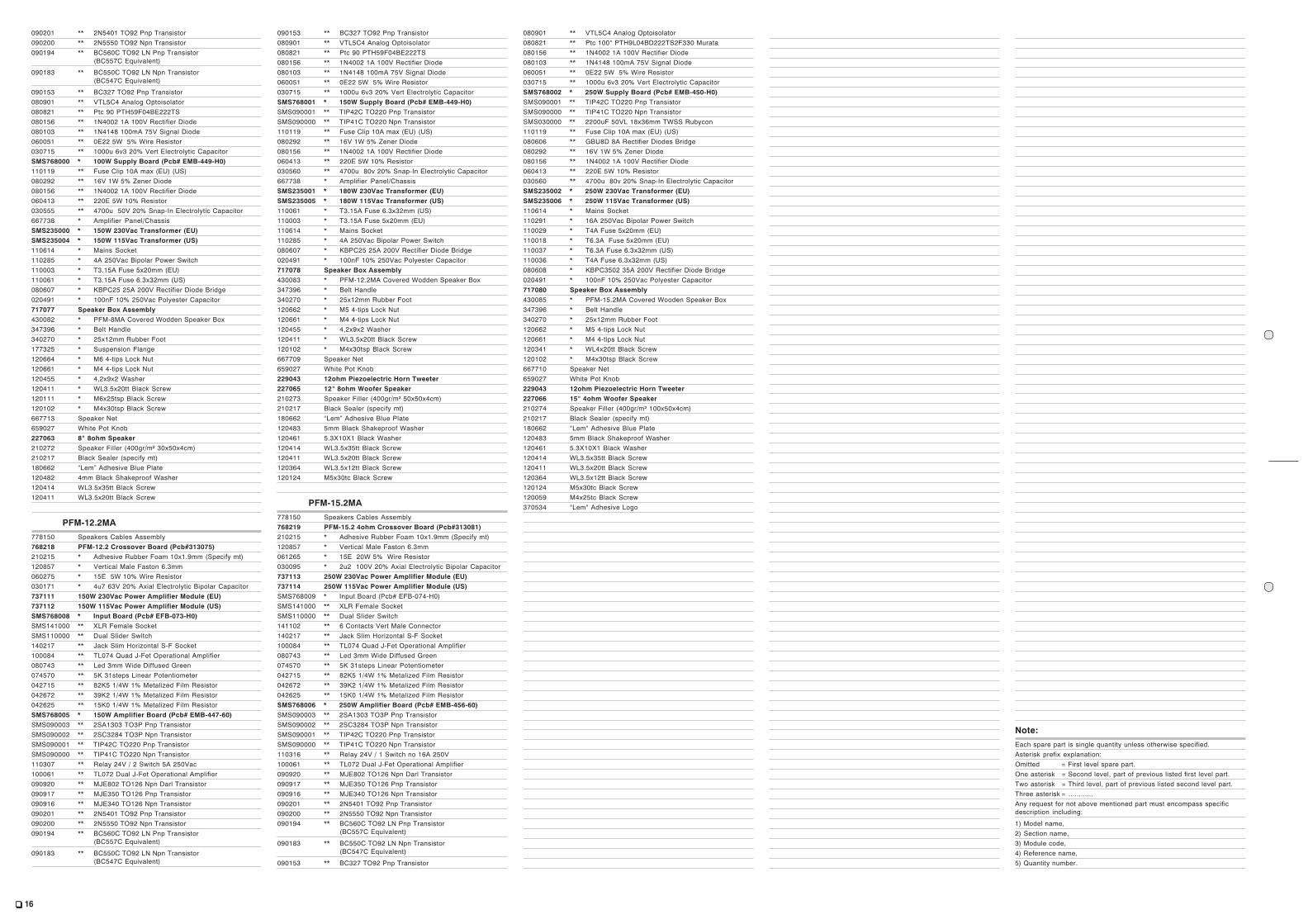
PFM-12.2MA
778150 Speakers Cables Assembly768218 PFM-12.2 Crossover Board (Pcb#313075)210215 * Adhesive Rubber Foam 10x1.9mm (Specify mt)120857 * Vertical Male Faston 6.3mm060275 * 15E 5W 10% Wire Resistor030171 * 4u7 63V 20% Axial Electrolytic Bipolar Capacitor737111 150W 230Vac Power Amplifier Module (EU)737112 150W 115Vac Power Amplifier Module (US)SMS768008 * Input Board (Pcb# EFB-073-H0)SMS141000 ** XLR Female SocketSMS110000 ** Dual Slider Switch140217 ** Jack Slim Horizontal S-F Socket100084 ** TL074 Quad J-Fet Operational Amplifier080743 ** Led 3mm Wide Diffused Green074570 ** 5K 31steps Linear Potentiometer042715 ** 82K5 1/4W 1% Metalized Film Resistor042672 ** 39K2 1/4W 1% Metalized Film Resistor042625 ** 15K0 1/4W 1% Metalized Film ResistorSMS768005 * 150W Amplifier Board (Pcb# EMB-447-60)SMS090003 ** 2SA1303 TO3P Pnp TransistorSMS090002 ** 2SC3284 TO3P Npn TransistorSMS090001 ** TIP42C TO220 Pnp TransistorSMS090000 ** TIP41C TO220 Npn Transistor110307 ** Relay 24V / 2 Switch 5A 250Vac100061 ** TL072 Dual J-Fet Operational Amplifier090920 ** MJE802 TO126 Npn Darl Transistor090917 ** MJE350 TO126 Pnp Transistor090916 ** MJE340 TO126 Npn Transistor090201 ** 2N5401 TO92 Pnp Transistor090200 ** 2N5550 TO92 Npn Transistor090194 ** BC560C TO92 LN Pnp Transistor
(BC557C Equivalent)
090183 ** BC550C TO92 LN Npn Transistor(BC547C Equivalent)
090153 ** BC327 TO92 Pnp Transistor080901 ** VTL5C4 Analog Optoisolator080821 ** Ptc 90 PTH59F04BE222TS080156 ** 1N4002 1A 100V Rectifier Diode080103 ** 1N4148 100mA 75V Signal Diode060051 ** 0E22 5W 5% Wire Resistor030715 ** 1000u 6v3 20% Vert Electrolytic CapacitorSMS768001 * 150W Supply Board (Pcb# EMB-449-H0)SMS090001 ** TIP42C TO220 Pnp TransistorSMS090000 ** TIP41C TO220 Npn Transistor110119 ** Fuse Clip 10A max (EU) (US)080292 ** 16V 1W 5% Zener Diode080156 ** 1N4002 1A 100V Rectifier Diode060413 ** 220E 5W 10% Resistor030560 ** 4700u 80v 20% Snap-In Electrolytic Capacitor667738 * Amplifier Panel/ChassisSMS235001 * 180W 230Vac Transformer (EU)SMS235005 * 180W 115Vac Transformer (US)110061 * T3.15A Fuse 6.3x32mm (US)110003 * T3.15A Fuse 5x20mm (EU)110614 * Mains Socket110285 * 4A 250Vac Bipolar Power Switch080607 * KBPC25 25A 200V Rectifier Diode Bridge020491 * 100nF 10% 250Vac Polyester Capacitor717078 Speaker Box Assembly430083 * PFM-12.2MA Covered Wodden Speaker Box347396 * Belt Handle340270 * 25x12mm Rubber Foot120662 * M5 4-tips Lock Nut120661 * M4 4-tips Lock Nut120455 * 4,2x9x2 Washer120411 * WL3.5x20tt Black Screw120102 * M4x30tsp Black Screw667709 Speaker Net659027 White Pot Knob229043 12ohm Piezoelectric Horn Tweeter227065 12" 8ohm Woofer Speaker210273 Speaker Filler (400gr/m² 50x50x4cm)210217 Black Sealer (specify mt)180662 “Lem” Adhesive Blue Plate120483 5mm Black Shakeproof Washer120461 5.3X10X1 Black Washer120414 WL3.5x35tt Black Screw120411 WL3.5x20tt Black Screw120364 WL3.5x12tt Black Screw120124 M5x30tc Black Screw
PFM-15.2MA
778150 Speakers Cables Assembly768219 PFM-15.2 4ohm Crossover Board (Pcb#313081)210215 * Adhesive Rubber Foam 10x1.9mm (Specify mt)120857 * Vertical Male Faston 6.3mm061265 * 15E 20W 5% Wire Resistor030095 * 2u2 100V 20% Axial Electrolytic Bipolar Capacitor737113 250W 230Vac Power Amplifier Module (EU)737114 250W 115Vac Power Amplifier Module (US)SMS768009 * Input Board (Pcb# EFB-074-H0)SMS141000 ** XLR Female SocketSMS110000 ** Dual Slider Switch141102 ** 6 Contacts Vert Male Connector140217 ** Jack Slim Horizontal S-F Socket100084 ** TL074 Quad J-Fet Operational Amplifier080743 ** Led 3mm Wide Diffused Green074570 ** 5K 31steps Linear Potentiometer042715 ** 82K5 1/4W 1% Metalized Film Resistor042672 ** 39K2 1/4W 1% Metalized Film Resistor042625 ** 15K0 1/4W 1% Metalized Film ResistorSMS768006 * 250W Amplifier Board (Pcb# EMB-456-60)SMS090003 ** 2SA1303 TO3P Pnp TransistorSMS090002 ** 2SC3284 TO3P Npn TransistorSMS090001 ** TIP42C TO220 Pnp TransistorSMS090000 ** TIP41C TO220 Npn Transistor110316 ** Relay 24V / 1 Switch no 16A 250V100061 ** TL072 Dual J-Fet Operational Amplifier090920 ** MJE802 TO126 Npn Darl Transistor090917 ** MJE350 TO126 Pnp Transistor090916 ** MJE340 TO126 Npn Transistor090201 ** 2N5401 TO92 Pnp Transistor090200 ** 2N5550 TO92 Npn Transistor090194 ** BC560C TO92 LN Pnp Transistor
(BC557C Equivalent)
090183 ** BC550C TO92 LN Npn Transistor(BC547C Equivalent)
090153 ** BC327 TO92 Pnp Transistor
080901 ** VTL5C4 Analog Optoisolator080821 ** Ptc 100° PTH9L04BD222TS2F330 Murata080156 ** 1N4002 1A 100V Rectifier Diode080103 ** 1N4148 100mA 75V Signal Diode060051 ** 0E22 5W 5% Wire Resistor030715 ** 1000u 6v3 20% Vert Electrolytic CapacitorSMS768002 * 250W Supply Board (Pcb# EMB-450-H0)SMS090001 ** TIP42C TO220 Pnp TransistorSMS090000 ** TIP41C TO220 Npn TransistorSMS030000 ** 2200uF 50VL 18x36mm TWSS Rubycon110119 ** Fuse Clip 10A max (EU) (US)080606 ** GBU8D 8A Rectifier Diodes Bridge080292 ** 16V 1W 5% Zener Diode080156 ** 1N4002 1A 100V Rectifier Diode060413 ** 220E 5W 10% Resistor030560 ** 4700u 80v 20% Snap-In Electrolytic CapacitorSMS235002 * 250W 230Vac Transformer (EU)SMS235006 * 250W 115Vac Transformer (US)110614 * Mains Socket110291 * 16A 250Vac Bipolar Power Switch110029 * T4A Fuse 5x20mm (EU)110018 * T6.3A Fuse 5x20mm (EU)110037 * T6.3A Fuse 6.3x32mm (US)110036 * T4A Fuse 6.3x32mm (US)080608 * KBPC3502 35A 200V Rectifier Diode Bridge020491 * 100nF 10% 250Vac Polyester Capacitor717080 Speaker Box Assembly430085 * PFM-15.2MA Covered Wooden Speaker Box347396 * Belt Handle340270 * 25x12mm Rubber Foot120662 * M5 4-tips Lock Nut120661 * M4 4-tips Lock Nut120341 * WL4x20tt Black Screw120102 * M4x30tsp Black Screw667710 Speaker Net659027 White Pot Knob229043 12ohm Piezoelectric Horn Tweeter227066 15" 4ohm Woofer Speaker210274 Speaker Filler (400gr/m² 100x50x4cm)210217 Black Sealer (specify mt)180662 "Lem" Adhesive Blue Plate120483 5mm Black Shakeproof Washer120461 5.3X10X1 Black Washer120414 WL3.5x35tt Black Screw120411 WL3.5x20tt Black Screw120364 WL3.5x12tt Black Screw120124 M5x30tc Black Screw120059 M4x25tc Black Screw370534 "Lem" Adhesive Logo
Note:
Each spare part is single quantity unless otherwise specified.Asterisk prefix explanation:Omitted = First level spare part.One asterisk = Second level, part of previous listed first level part.Two asterisk = Third level, part of previous listed second level part.Three asterisk = ............Any request for not above mentioned part must encompass specificdescription including:
1) Model name,2) Section name,3) Module code,4) Reference name,5) Quantity number.