27064203 department of defense mil hdbk 1028 3 military handbook maintenance facilities for...
TRANSCRIPT

8/8/2019 27064203 Department of DEFENSE Mil Hdbk 1028 3 Military Handbook Maintenance Facilities for Ammunition Explo…
http://slidepdf.com/reader/full/27064203-department-of-defense-mil-hdbk-1028-3-military-handbook-maintenance 1/43
AMSC WA
MIL-HDBK-1028/3
31 DECEMBER 1987
SUPERSEDING
NAVFAC DM-28.03
NOVSMBER 1981
MILITARY HANDBOOK
MAINTENANCE FACILITIES FOR
AMMUNITION, EXPLOSIVES ,
AND TOXINS
o
).
.’
. a
w
DISTRiBUllONTATEMENTA APPROVED FOR PUBLIC RELEASE DISTRIBUTION ISUNLIMITED
AREA FACR
Downloaded from http://www.everyspec.com on 2010-01-25T16:27:07.
8/8/2019 27064203 Department of DEFENSE Mil Hdbk 1028 3 Military Handbook Maintenance Facilities for Ammunition Explo…
http://slidepdf.com/reader/full/27064203-department-of-defense-mil-hdbk-1028-3-military-handbook-maintenance 2/43
tiIL-HDBK-1028/3
ii
Downloaded from http://www.everyspec.com on 2010-01-25T16:27:07.
8/8/2019 27064203 Department of DEFENSE Mil Hdbk 1028 3 Military Handbook Maintenance Facilities for Ammunition Explo…
http://slidepdf.com/reader/full/27064203-department-of-defense-mil-hdbk-1028-3-military-handbook-maintenance 3/43
MIL-HDBK- 1028/3
! ABSTRACT
This handbook presents basic design guidance for ammunition,
explosives , and toxins maintenance facilities covered by Category Group 216
For Military Real Property. It has been developed ,from extensive re-
evaluation of facilities and it is intended for use by experienced
architects and engineers. The contents include design data for buildings andshop areas to provide facilities for repairing and maintaining ammunition,
rockets, bombs, mines, grenades, torpedos, depth charges, air/underwater
weapons, demolition materials, pyrotechnics, guided missile fuels, ammunition
parts, and related chemicals.
I
II
!1
. . .111
Downloaded from http://www.everyspec.com on 2010-01-25T16:27:07.
8/8/2019 27064203 Department of DEFENSE Mil Hdbk 1028 3 Military Handbook Maintenance Facilities for Ammunition Explo…
http://slidepdf.com/reader/full/27064203-department-of-defense-mil-hdbk-1028-3-military-handbook-maintenance 4/43
MIL-HDBK- 1028/3
iv
Downloaded from http://www.everyspec.com on 2010-01-25T16:27:07.
8/8/2019 27064203 Department of DEFENSE Mil Hdbk 1028 3 Military Handbook Maintenance Facilities for Ammunition Explo…
http://slidepdf.com/reader/full/27064203-department-of-defense-mil-hdbk-1028-3-military-handbook-maintenance 5/43
MIL-HDBK- 1028/3
FOREWORD
This handbook has been developed from an evaluation of facilities in the
Shore Establishment, surveys of the availability of new materials and
construction methods, and selection of the best design practices of the Naval
Facilities Engineering Command (NAVFACENGCOM) , other Government agencies, and
the private sector. This handbook uses, to the maximum extent feasible,national professional society, association, and institute standards
Deviations from this criteria, in the planning, engineering, design, and
construction of Naval shore facilities, cannot be made without prior approval
of NAVFACENGCOM Code 04.
Recommendations for improvement are encouraged from within the Navy, other
Government agencies, and the private sector ano should be furnished on the
. DOD Form 1426 provided inside the back cover to Commander, Atlantic Division,
Code 04A4, Naval Facilities Engineering Command, Norfolk, VA 23511-6287,
telephone commercial (804) 444-9970.
THIS HANDBOOK SHALL NOT BE USED AS A REFERENCE DOCUMENT FOR PROCUREMENT OF
FACILITIES CONSTRUCTION IT IS TO BE USED IN THE PURCHASE OF FACILITIESENGINEERING STUDIES AND DESIGN (FINAL PLANS, SPECIFICATIONS, AND COST
ESTINATES) DO NOT REFERENCE
OTHER PROCUREMENT DOCUMENTS .
IT IN MILITARY OR FEDERAL SPECIFICATIONS OR
v
Downloaded from http://www.everyspec.com on 2010-01-25T16:27:07.

8/8/2019 27064203 Department of DEFENSE Mil Hdbk 1028 3 Military Handbook Maintenance Facilities for Ammunition Explo…
http://slidepdf.com/reader/full/27064203-department-of-defense-mil-hdbk-1028-3-military-handbook-maintenance 6/43
Criteria
Numbeq
MIL-HDBK-1028/l
MIL-HDBK- 1028/3
DM-28.04
DM-28.05
MIL-HDBK-1028/6
MIL-HDBK-1028/8
MIL-HDBK-1028/3
~
~
Aircraft Maintenance Facilities
Maintenance Facilities forAmmunition, Explosives, and Toxins
General Maintenance Facilities
Environmental Control - Design of
Clean Rooms
Aircraft Fixed Point Utility Systems
Pest Control Facilities
&
IANTDIV
IANTDIV
WESTDIV
LANTDIV
HDQTRS
HDQTRS
NOTE: Design manuals, when revised, will be converted to military handbooks.
This handbook is issued to provide immediate guidance to the user.
However, it may or may not conform to format requirements of
MIL-HDBK- 1006/3 and will be corrected on the next update.
vi
q
Downloaded from http://www.everyspec.com on 2010-01-25T16:27:07.

8/8/2019 27064203 Department of DEFENSE Mil Hdbk 1028 3 Military Handbook Maintenance Facilities for Ammunition Explo…
http://slidepdf.com/reader/full/27064203-department-of-defense-mil-hdbk-1028-3-military-handbook-maintenance 7/43
MIL-HDBK-1028/3
CONTENTS
Section 1
1.1
1.2
1.31.4
1.5
1.6
1.7
1.8
1.9
1.10
1.10.1
1.10.2
1.11
Section 2
2.12.2
2.2.1
2.2.1.1
2.2.1.2
2.2.1.3
2.2.1.4
2.2.1.5
2.2.1.6
2.2.1.7
2.2.1.8
2.2.2
2.2.2.1
.2.2.2.22.2.2.3
2.2.2.4
2.3
2.3.1
2.3.2 ~
2.3.3
2.3.4
2.3.5
2.4
2.4.1
2.4.2
2.4.3
2.5
INTRODUCTION
Ease
Scope ..................................................
Cancellation ...........................................
General Structural Requirements ....................Energy Conservation ................................ .
Building Protection ....................................
Loading Dock Ramp Protection ...........................
Fire Protection ......................................
Radio Frequency Interference (RFI) Protection ..........
Security ................. . . ........... . . .......
Safety ...............................................
Minimum Separation Distances ..........................
System Safety Engineering. ........................... .
Design Review Requirements .............................
1
1
1
1
1
1
1
1
1
2
2
2
2
GENERAL AMMUNITION MAINTENANCE SHOPS
Function ............................................... 3Architectural and Structural Requirements .............. 3
Spaces ................................................. 3
Main Shop Area ....................................... 3
Office Space ........ .. . . . . ................ 3
Toilets ................................................ 3
Cleaning Gear ...................................... 3
Storage ................................................ 3
Mechanical Equipment Room .............................. 3
Paint Shop ........................................... 3
Test Cells ...........’.................................. 3
Design ................................................. 4
Walls .................................................. 4
Floors ................................................. 4Roofs .......................... ...................... 4
Doors .................................................. 4
Mechanical Requirements ........................... 4
Heating and Air Conditioning .......................... 4
Ventilation ............................................ 4
Plumbing ............................................. 5
Compressed Air ..................................... 5
Noise and Vibration Control .......................... 5
Electrical Requirements .......................... 5
Power .................................................. 5
Lighting ................. . . . . ............... 6
Grounding and Lightning Protection .................... 6
Explosion-Proof Weight-Handling Equipment .............. 6
Section 3 BOMB-TYPE ANMUNITION MAINTENANCE SHOPS
3.1 Function ............................................... 7
3.2 Architectural and Structural Requirements .............. 7
3.2.1 Spaces .............................................. . 7
3.2.2 Design ............................................. 7
vii
Downloaded from http://www.everyspec.com on 2010-01-25T16:27:07.
8/8/2019 27064203 Department of DEFENSE Mil Hdbk 1028 3 Military Handbook Maintenance Facilities for Ammunition Explo…
http://slidepdf.com/reader/full/27064203-department-of-defense-mil-hdbk-1028-3-military-handbook-maintenance 8/43
MIL-HDBK-1028/3
3.3
3.3.1
3.3.2
3.3.3
3.3.4
3.3.5
3.63.4.1
3.4.2
3.4.3
3.4.4
3.5
Section 4
4.1
4.2
4.2.1
6.2.2
4.3
&.3.l4.3.2
4.3.3
4.3.4
4.3.5
4.f4
Section 5
5.1
5.1.1
5.1.2
5.2
5.3
5.3.1
5.3.2
5.3.2.1
5.3.2.2
5.3.2.3
5.3.2.4
5.3.2.5
5.3.2.6
5.3.2.7
5.3.2.8
5.3.2.9
5.4
5.4.1
5.4.2
5.4.3
5.4.3.1
5.4.3.2
5.4.4
5.4.5
E??&e~
Mechanical Requirements.. .......................... 7
Heating and Air Conditioning .......................... J
Ventilation ....................................... .. 7
Plumbing. ................. ........................ .. 7
Compressed Air ..................................... 8
Noise and Vibration Control ............................ 8
Electrical Requirements.. .............................. 8Power .............................................. 8
Lighting ............................................. . 8
Emergency Power ...................................... 9
Grounding and Lightning Protection ............ ..... 9
Explosion-Proof Weight-Handling Equipment .............. 9
PROPELLANT POWDER MAINTENANCE SHOPS
Function ...............................................
Architectural and Structural Requirements ..............
Spaces .................................................
Design ..................................................
Mechanical Requirements ............................. ..
Heating and Air Conditioning. ...........................Ventilation, .........................................
Plumbing .............................................
Compressed Air .......................................
Noise and Vibration Control ................... ........
Electrical Requirements .......................... .. ..
AIR/UNDERWATER WRAPONS SHOPS
10
10
10
10
10
1010
10
10
10
10
qFunction and Scope .....................................11
Function ............................................... 11
Scope ..................... . ......... ....... 11
Location ............................................... 11
Architectural and Structural Requirements .............. 11
Layout .................................................11
Design ................................................. 11
Shops and Torpedo Storage. .............................11
Otto Fuel Ready Storage Room ........................... 11
Defueling/Fueling/Af terbody Breakdown Room ............. 12
Vaults ...................................................12
Vehicle Storage Shed ................................. . 12
Paint Shop .............................................12
Shower and Change Rooms ................................ 12
Coffee Mess ............................................ 12
Exterior Pavement ......................................12
Mechanical Requirements ................................12
Heating and Air Conditioning ........................ 12
Ventilation .......................................... 13
Plumbing ............................................. 13
Design Requirements ................................. .. 13
Station Responsibility .................................17
Compressed Air ...................................... ..14
Noise and Vibration Control ............................14
. . .VIII
Downloaded from http://www.everyspec.com on 2010-01-25T16:27:07.
8/8/2019 27064203 Department of DEFENSE Mil Hdbk 1028 3 Military Handbook Maintenance Facilities for Ammunition Explo…
http://slidepdf.com/reader/full/27064203-department-of-defense-mil-hdbk-1028-3-military-handbook-maintenance 9/43
5.5
5.5.1
5.5.2
5.5.3
5.5.3.1
5.5.3.2
5.5.3.3
5.5.4
5.5.5
5.5.6
5.5.7
5.5.8
5.6
5.6.1
5.6.2
5.6.3
5.6.45.6.5
5.6.6
5.7
5.8
Section 6
6.1
6.2
6.3
6.3.1
6.3.2
6.3.3
6.3.46.4
6.4.1
6.4.2
6.4.3
6.4.4
6.5
6.5.1
6.5.2
6.5.3
6.5.4
6.5.5
6.6
6.6.1
6.6.2
6.6.3
FACILITY PIATES
Otto II Fuel
MIL-HDBK-1028/3
m
Requirements .......................... . 14
General ............................................... 14Fuel Tank Turnaround/Afterbody Breakdowm Rooms
Layout. ................... ........................... 14
Ventilation System ................................ 15
OttoFuelI IHandling . .... ........................... 15
Air Supply System ..................................... 15
Exhaust System ........................................ 15
Hood Requirements ...................................... 15
Air Velocity Requirements .......................... 16
System Controls ....................................... 16
Other Design Considerations .......................... 16
Design Review Requirements ........................... 16
Electrical Requirements.. ............................. 16
power .............................................. 16
Lighting .............................................. 17
Emergency Power ..................................... 17
Shielding ............................................ 17Grounding and Lightning Protection .................... 17
Communications ........................................ 17
Security ............................................. 17
Explosion-Proof Weight-Handling Equipment ............. 17
QUALITY EVALUATION LABORATORY
Function ............................................. 18
Location .............................................. 18
Layout ......... . . ........ . ................. 18
Office Wing .......................................... 18
Chemical Testing Wing..... ........................... 18
Test Cell Wing ....................................... 18
Mechanical and Electronics Wing ....................... 18Architectural and Structural Requirements ............. 18
Walls ................................................. 18
Roofs ................................................. 18
Floors ................................................ 18
Retaining Walls and Barricades ....................... 19
Mechanical Requirements ........................... 19
Heating and Air Conditioning .......................... 19
Ventilation ........................................... 19
Plumbing ............................................. 19
Compressed Air ......... . . ........................ 19
Noise and Vibration Control .......................... 19
Electrical Requirements .......... . .. ............... 19
Shielding ........ . . . . . . . ......... . . 19
Power .................................................. 19
Lighting ........ . . . . . ...................... 20
. . . . . . . . . . . . . . . . . . . . . . . . . . . . . . . . . . . . . . . . . . . . . 21
REFERENCES . . . . . . . . . . .............................. . 30
ix
Downloaded from http://www.everyspec.com on 2010-01-25T16:27:07.

8/8/2019 27064203 Department of DEFENSE Mil Hdbk 1028 3 Military Handbook Maintenance Facilities for Ammunition Explo…
http://slidepdf.com/reader/full/27064203-department-of-defense-mil-hdbk-1028-3-military-handbook-maintenance 10/43
MIL-HDBK-1028/3
Section 1: INTRODUCTION
1.1 -. This handbook presents criteria for ammunition,
explosives, and toxins maintenance facilities at naval shore activities.
Special requirements for the individual project must be obtained from Naval
Facilities Engineering Command Headquarters (NAVFACENGCOM HQ) or the
cognizant management command or bureau.
1.2 Cancellation. This handbook cancels and supersedes NAVFAC
DM-28.03, November 1981, and NAVFAC DD-1291743, Air/Underwater WeaDonsShOp
Refer to Facility Plate Sheets in Appendix A.
1.3 General Structural Requirements. The structural design shall be
in accord with NAVFAC P-355, Structural Enrineerine - Seismic Desire for
Buildines. , NAVFAC DM-2 Series, Structural En~ineering, and NAVFAC P-397,
Structures to Resist the Effects of Accidental Explosions.
1.4 EnerEV Conservation. Energy conservation shall be a major
consideration in the design of building envelopes, mechanical systems, and
electrical systems for maintenance facilities for ammunition, explosives, andtoxins (refer to NAVFAC DM-3.03, Heatine. Ventilating, Air Conditioning and
Dehumidifying Systems, and NAVFACINST 4101.1, Energy Budgets for New
Facilities) . Each building envelope shall be insulated to provide the
minimum heat transmission (“U”) factors practical to meet Energy Budgets and
to comply with the requirements of MIL-HDBK-1190, Facility Planninz and
Desivn Guide.
1.5 Building Protection. The building structure of all maintenance
facilities, including corners, doors, structural members, etc. , shall be
protected from damage by vehicles and moving loads by the installation of
concrete filled pipe guards, bumpers, railings, corner guards, and similar
protective features.
1.6 Loading Dock Ramu Protection. Each facility requiring a loading
dock ramp shall be provided side edge protection in accord with Section
1910.23c, Occupational Safety and Health Act Standards Manual.
1.7 Fire Protection. Fire protection for all maintenance facilities
for ammunition, explosives, and toxins shall be provided in accord with
requirements in para. 3.2, NAVSRA OP-5 , Volume 1, Ammunition and Explosives
Ashore and MIL-HDBK-1OO8, Fire Protection for Facilities Eneineerin~ Desire!
and Construction.
1.B Radio Freauency Interference Protection. Where Electro -Explosive
Devices (EED) are handled, tested, and installed, consideration should be ,given to specifying a Radio Frequency Interference (RFI) shielded room that
provides decibel attenuation to reduce the field intensities to a NON-HERO
unsafe ordnance level. For further details regarding RFI hazards, refer to
NAVSSA OP-3565, Electroma~entic Radiation Hazards (Hazards to Ordnance) , and
NAVAIR TM 16-1-529, Technical Manual.
1.9
toxins
Security. Maintenance facilities for ammunition, explosives, and
shall be located so that physical security can be provided in accord
1
Downloaded from http://www.everyspec.com on 2010-01-25T16:27:07.
8/8/2019 27064203 Department of DEFENSE Mil Hdbk 1028 3 Military Handbook Maintenance Facilities for Ammunition Explo…
http://slidepdf.com/reader/full/27064203-department-of-defense-mil-hdbk-1028-3-military-handbook-maintenance 11/43
MIL-HDBK- 1028/3
with OPNAVINST 5530.14A, United States Navv Physical Securitv Manual and LOSS .
Prevention Manual. @
1.10 Sat&x. Designs of facilities shall comply with MIL-HDBK- 1006/1,
Policy and Procedures for Construction Drawings and Specifications
Preparation, and appropriately meet the latest change of Vol. 1, NAVSSA OP-5,
1.10.1 Minimum Separation Distances. When locating structures , refer to
data in Vol. 1, NAVSRA OP-5, to safeguard personnel and neighboringstructures.
1.10.2 Svstem Safetv Engineering. For general information on the
Department of the Navy’s System Safety Engineering Program, refer to
NAVFAC DM-1.01, Basic Architectural Requirements and Desien Cons idera~
1.11 Occupational Health Assistance. NAVFACINST 5100.11, mad
Safety and Health ProPram, requires that activities coordinate with their
local Naval Medical Command (NAVMEDCOM) industrial hygienist. during facility
planning stages. In addition, NAVMEDCOM has agreed to assign to each EFD the
full-time service of an industrial hygienist to help with system safety
engineering and provide technical health/industrial hygiene support as
necessary. The EFD industrial hygienist will identify, evaluate, and providerecommendations for controlling potential health hazards such as toxic
materials, non-ionizing radiation, and noise. They shall participate. in
design review of plans and specifications for the selected projects.
2
Downloaded from http://www.everyspec.com on 2010-01-25T16:27:07.
8/8/2019 27064203 Department of DEFENSE Mil Hdbk 1028 3 Military Handbook Maintenance Facilities for Ammunition Explo…
http://slidepdf.com/reader/full/27064203-department-of-defense-mil-hdbk-1028-3-military-handbook-maintenance 12/43
MIL-HDBK-1028/3
Section 2: GENERAL AMMUNITION MAINTENANCE SHOPS
—
2.1 Function . General ammunition maintenance shops provide facilities
for maintenance of projectiles, fixed ammunition, rockets, fuses, primers,
black powder cartridges and units, mortar ammunition, small-arms ammunition,
pyrotechnic material, and inert material. Most ~unitiOn rewOrk and
overhaul shops and most rocket rework and overhaul shops would be included in
this grouping.
2.2 Architectural and Structural Requirements
2.2.1 ~. Paras. 2 .2.1.1 through 2.2.1.8 describe areas that are
normally required in general ammunition maintenance shops.
2.2.1.1 Main Shou Area. A main shop area is usually an extensive area
occupying the major portion of the building and sometimes divided into a
series of work bays Normally included in the main shop area are
assembly/disassembly, leak testing, component testing, and repair OperatiOns.
2.2.1.2 Office Space. An enclosed office space, which must be kept to a
minimum, shall be provided for clerical tasks and record storage.
2.2.1.3 Toilets. Toilet facilities shall be provided for both male and
female personnel.
2,2.1.4 Cleaning Gear. Cleaning gear and janitorial storage space shall
be provided.
2.2.1.5 StOrave. Space shall be provided for storing and maintaining
tools and equipment used in shop operations.
2.2.1.6 Mechanical Eauiument Room. An equipment room shall be provided tohouse mechanical equipment necessary to support building and shop functions.
2.2.1.7 ~Q An enclosed paint shop shall be provided in accord
with National Fire Protection Association, Inc. , NFPA 33, SDraY Application
Usin.eFlammable and Combustible Materials, NFPA 91, Blower and Exhaust
Svstems, when requirements for painting are a part of ammunition maintenance
operations. A spray paint booth should be considered depending on the type
of painting operation required. Exterior lockers, located at least 50 ft
(15.24 m) from.the maintenance building, or an approved flammable liquid
storage room shall be provided for paint storage. space for a grit blast
chamber shall be provided in facilities where major repainting is done on
heavy, thick-walled containers such as projectiles. Locate dust collector
and/or a baghouse for grit blast cleaning equipment outside the building.Grit blast chamber construction shall comply with American National Standards
Institute (ANSI) standards, ANSI z9.4-1985, Ventilation and Safe Practices of
Abrasive Blastine Operations.
2.2.1.8 Test Cells. A reinforced concrete test cell may be required when
ordnance disassembly, check out, and reassembly are a part of the ammunition
maintenance operations. The latest test cell requirements should be obtained
from the Naval Civil Engineering Laboratory (NCEL), Port Hueneme, CA.
3
Downloaded from http://www.everyspec.com on 2010-01-25T16:27:07.
8/8/2019 27064203 Department of DEFENSE Mil Hdbk 1028 3 Military Handbook Maintenance Facilities for Ammunition Explo…
http://slidepdf.com/reader/full/27064203-department-of-defense-mil-hdbk-1028-3-military-handbook-maintenance 13/43
MIL-HDBK-1028/3
2.2.2 W. The building will normally be a single-story structure
and shall be constructed of noncombustible materials Refer to para. 6-3.1,
NAVSIM OP-5 , Volume 1, and NAVFAC P-397, for general design and construction
requirements for ammunition and explosive operating buildings Loading/un-
loading docks shall be provided for rail cars or trucks as determined by the
location of the facility. Standard construction materials , and finishes
shall be in accorl with NAVFAC DM-1 Series , Architecture, and NAVFAC DM-2
Series , Structural Eruzineering. Special construction, materials , andfinishes shall be in accord with paras . 2.2.2.1 through 2.2.2.4.
@
2.2.2.1 WaJ.&.. Walls of main shop areas shall be reinforced concrete.
Utilize barricades and blast walls to separate shop bays or work areas when
eXPIOS ive hazards exist, depending on the nature of the operations involved.
Refer to para. 6-3.l.2d, Volume 1, NAVSRA OP-5, for further information on
substantial dividing walls.
2.2.2.2 Floors. Floors shall be reinforced concrete Conductive <spark
proof floor finish shall be provided in areas where black powder’ or other
high explosive is handled. Spark-resistant floors shall conform to Guide
Specific?t.ionNFGS-09785 , Metallic-Tw e Conductive and SDark-Resistance
Concrete Floor Finish. Resilient floor finish shall be provided for affice
space only.
2.2.2.3 m. Roofs in nonexplosives areas should normally be reinforced
concrete. Frangible roof sections shall be provided in explosive areas in
accord with NAVFAC P-397.
2.2.2.4 m. Blastproof sliding doors shall be provided at both ends of
main shop’areas. Door openings shall be of adequate size to allow forklifts qto move the largest anticipated containers in and out of the shop area.
Blastproof personnel access doors with panic hardware shall be provided at
both ends of shop areas. With the use of additional blastproof doors , the
facility may be segmented as necessary. Refer to para. 6-3.1.3, Vulume 1,
NAVSEA OP.5, for further information on building exits.
2.3 Mechanical Requirements. Mechanical requirements are defined in
paras. 2.3.1 through 2.3.5 of this handbook.
2.3.1 Heating and Air Conditioning. Heating and air conditioning,
‘including humidity control; shall be provided for main shop areas as required
by the type of ordnance being maintained and in accord with NAVFAC DM..3.03.
Where air conditioning is required for main shop areas, office spaces shall
also be air conditioned. Heating only shall be provided for other spaces.
Inside design temperatures, for controlled areas, shall be 78° F (26° C) with
a maximum relative humidity of 50 percent for cooling and 65° F (18° C) for
heating unless type of ordnance requires different conditions . Refer toparas 6-3.2.6 and 6-3.2.7, Volume 1, NAVS!M OP-5, for general guidance.
2.3.2 Ventilation. Ventilation shall be provided in accord with NAVFAC
DM-3.03 and para. 6-3.2.7, Volume 1, NAVSRA OP-5. Specifically provide:
a) Exhaust ventilation system with makeup air, heated as re-
quired, for the paint shop. The ventilation system shall be in accord with
NFPA 33., q
4
Downloaded from http://www.everyspec.com on 2010-01-25T16:27:07.
8/8/2019 27064203 Department of DEFENSE Mil Hdbk 1028 3 Military Handbook Maintenance Facilities for Ammunition Explo…
http://slidepdf.com/reader/full/27064203-department-of-defense-mil-hdbk-1028-3-military-handbook-maintenance 14/43
b)
system if grit
c)
MIL-HDBK-1028/3
Makeup air, heated as required, for dust collectOr exhaust
blast cleaning equipment is provided.
Ventilation for battery shop, if battery charging equipment is
suppli”ed, as required by Section 5, Part 6, NAVFAC DM-28.04, General Main-
te&nce Facilities.
2.3.3 Plumbing. Plumbing shall be provided in accordance with NAVFAC
DM-3.01, Mechanical Eneineerine - PlumbinT Svstems. Specifically provide:
a) cold water supplies with hose -bibb Out.lets tO main shOp areas.
Steam or hot water supplies to main shop areas that require washout opera-
tions. Cold water supply to the paint booth when waterwash type is provided.
Hose -bibb outlets shall be equipped with vacuum breakers.
b) Floor drains in main shop areas and a drainage system for the
paint booth when wate~ash twe is used. Connect drains to waste systernsas
required to comply with pollution control requirements (refer to
para. 6-3.2.2, Vol. 1, NAVSEA OP-5, for requirements concerning drain lines
handling explosive wastes) There shall be no drains from the paint spraybooths Floor draina may be connected to the sanitary system in areas where
there is no Otto fuel present. There shall be no floor drains in the Otto
fuel areas or provide trench and sump system for spill control.
c) Emergency showers and eyewashes when pyrotechnic or toxic
chemical materials are handled in the facility. Determine specific require-
ments based on materials used in the facility.
2.3.4 Compressed Air. Compressed air shall be provided at 100 psi (689
kPa) in accord with NAVFAC DM-3.05, CornDressedAir and Vacuum Svstems , for
air hoist motors , painting equipment, tools, etc. Provide outlets at work
benches and other work areas. Compressed air supplies shall be clean, dry
and utilize filters and dryers. Consider the requirements of the facility todetermine if a separate air compressor should be provided rather than
utilizing a central air supply. A separate air compressor would assure that
an adequate quantity of compressed air is available. Separate air compres -
sors may also provide lower operating and distribution costs. Refer to para.
7-2.5, Vol. 1, NAVSEA OP-5, for authorized use of compressed air.
2.3.5 Noise and Vibration Control. All mechanical systems and equipment
shall be designed to limit noise and vibration in accord with NAVFAC DM-3.10,
Noise and Vibration Control for Mechanical Eauipment (ARMY).
2.4 Electrical Requirements. Electrical requirements, including power
generation and distribution, lighting, grounding, and lightning protection
shall be in accord with Chapter 4, Vol. 1, NAVSEA OP-5, NFPA 70, National
Electrical Code, NAVFAC DM-4 Series, Electrical En~ineerinF, and as defined
in paras. 2.4.1 through 2.4.3 of this handbook.
2.4.1 w. Single-phase, 120 Vat, 20 A, 60 Hz, convenience outlets
shall be provided in all spaces with spacing as required by NFPA 70 and the
using activity. Equipment and wiring in the paint shop shall be in accord
with NFPA 33.
5
Downloaded from http://www.everyspec.com on 2010-01-25T16:27:07.
8/8/2019 27064203 Department of DEFENSE Mil Hdbk 1028 3 Military Handbook Maintenance Facilities for Ammunition Explo…
http://slidepdf.com/reader/full/27064203-department-of-defense-mil-hdbk-1028-3-military-handbook-maintenance 15/43
MIL-HDBK-1028/3
2.4.2 Liehtinp. Lighting shall meet the following criteria:
a) Interior lighting shall normally be fluorescent,@
b) Exterior lighting shall be high-pressure sodium vapor where
practical.
c) Design for lighting intensities shall be in accordance with
MIL-HDBK-1190, Facilitv Planninz and Desien Guide.
d) Fixtures and wiring in the paint shop shall be in accord with
NFPA 33.
2.4.3 Groundinz and Liehtnine Protection. Grounding and lighting
protection shall meet the following requirements:
a) Primary and secondary systems shall be provided (refer tc
Chapter 4, Volume 1, NAVSSA OP-5) .
b) Consider the use of cable reels for grounding conductors for
ordnance equipment in shop areas. Cable reels must be located so that they
do not interfere with overhead weight-handling equipment operations
c) Grounding in the paint shop shall be in accord with NFPA 33.
2.5 Exulosion-Proof Weieht-Handlinz Eauiument. Monorail hoists and/or
bridge cranes shall be provided in main shop areas, when the size of the
ammunition units to be maintained are large enough to warrant weight-handling
Monorail hoists and bridge cranes shall be of sparkproofq
quipment.
construction with explosion- proof motors if electric powered. Controls
shall be operable from floor level and, when they are electric, shall be
explosion proof. Classification of hazardous locations shall be as defined
in NFPA 70. Refer to NAVFAC DM-38.01, Wei~ht -Handlin~ Eauimnent, for
additional criteria.Colors for weight-handling equipment shall be accord
with NAVFAC P-309, Color for Naval Shore Facilities.
6
Downloaded from http://www.everyspec.com on 2010-01-25T16:27:07.
8/8/2019 27064203 Department of DEFENSE Mil Hdbk 1028 3 Military Handbook Maintenance Facilities for Ammunition Explo…
http://slidepdf.com/reader/full/27064203-department-of-defense-mil-hdbk-1028-3-military-handbook-maintenance 16/43
MIL-HDBK-1028/3
Section 3: BOMB-TYPE AMMONITION MAINTENANCE SHOPS
3.1 Function. These buildings provide facilities and shops for
maintenance of Class 1, Division 1 ammunition such as bombs, mines , warheads,
depth charges, and demolition material. Mine and depth charge rework and
overhaul shops would be included in this grouping.
3.2 Architectural and Structural Requirements
3.2.1 Suaces.. Spaces will generally be required as described in
para. 2.2.1. The following spaces shall also be required:
4 instrument rack storage,
b) instrument test room, and
c) battery maintenance area for mine rework facilities.
3.2.2 Desire. Design requirements described in para. 2.2.2 are ap.plicable to these facilities.
facilities
3.3
Battery charging equipment shall be provided for mine rework
in accord with Section 5, Part 6, NAVFAC DM-28 .04.
Mechanical Requirements
3.3.1 Heating Heating and air conditioning,
including humidity control, shall be provided for instrument test rooms in
accord with NAVFAC DM-3.03. Heating and air conditioning shall be provided
for main shop areas and the office. Humidity control shall be provided for
instrument rack storage for mine rework facilities. Heating only shall be
provided for other spaces. Inside design temperatures, for controlled areas ,shall be 78° F (26° C) with a maximum relative humidity of 50 percent for
cooling and 65° F (18° C) for heating. Maximum relative humidity for the
instrument test rooms and the instrument rack storage shall be as required
for the instruments to be maintained and stored in this area. Refer to
paras 6-3 .2.6 and 6-3.2.7, Volume 1, NAVSEA OP-5, for general guidance.
3.3.2 Ventilation. Ventilation requirements described in para. 2.3.2,
are applicable to these facilities and for the battery charging room in
compliance with Part 6, para. 7 .b, DM-28.04.
3.3.3 Plumbing. Plurbing shall be provided in accord with NAVFAC
DM-3 .01 and the following:
a) Cold water supplies, with hose -bibb outlets, to main shop
areas for normal floor maintenance. When waterwash type is supplied, cold
water supply to the paint booth. Hose -bibb outlets shall be equipped with
vacuum breakers.
b) F1OOK drains in main shop areas and a drainage system for the
paint booth when waterwash type is supplied. Connect drains to waste systems
7
Downloaded from http://www.everyspec.com on 2010-01-25T16:27:07.
8/8/2019 27064203 Department of DEFENSE Mil Hdbk 1028 3 Military Handbook Maintenance Facilities for Ammunition Explo…
http://slidepdf.com/reader/full/27064203-department-of-defense-mil-hdbk-1028-3-military-handbook-maintenance 17/43
MIL-HDBK-1028/3
as required to comply with pollution control requirements . Refer to
para.6-3.2.2, Volume 1, NAVSEA OP-5, for requirements concerning drainlines
handling explosive wastes. There shall be no drains from the paint spray
booths Floor drains may be connected to the sanitary system in areas where
there is no Otto fuel present. There shall be no floor drains in the Otto
fuel areas or provide trench and sump system for spill control.
c) Plumbing for the battery charging area in ‘compliance with Part
6, para. 7.c, DM-28.04.
3.3.4 Compressed Air. Compressed air shall be provided in accord with
NAVFAC DM-3.05. Specifically provide:
a) low-pressure compressed air as described in para. 2.3.4, and
b) high-pressure compressed air at 3,000 psi (20,684 kPa) to main
shop areas of torpedo rework facilities. Dryers and filters shall be
specified to assure a clean and dry air supply.
3.3.5 Noise and Vibration Control. All mechanical systems and equipment
shall be designed to limit noise and vibration in accord with NAVFAC DM-3.10.
3.L Electrical Requirements . Electrical requirements, including power
generation and distribution, lighting, grounding, and lightning protection
shall be in accord with Chapter 4, Volume 1 of NAVSEA OP-5; NFPA 70; NAVFAC
DM-4 Series; and the requirements defined in paras . 3.4.1 through 3.4.4.
shall also apply.
3.4.1 =. The following power requirements shall apply:
a) Single-phase, 120 Vac, 20 A, 60 Hz convenience outlets shall
be provided in all spaces with spacing as required by NFPA 70 and use:r
requirements.
b) Three-phase, 120/208 Vat, 60 Hz power outlets shall be
provided in main shop areas and instrument test rooms.
c) Three -phasel 115/200 Vat, 400 Hz and 28 Vdc power is required
for main shop areas and the instrument test room (refer to MIL-STD -704,
Aircraft Electric Power Characteristics, for 400 Hz and 28 Vdc requirements)
d) The ampacity of 3-phase and direct-current outlets shall be as
required by the using agency for the specific facility. Provide name plates
to indicate outlet characteristics.
e) Equipment aridwiring in the paint shop shall be in accord withNFPA 33.
3.4.2 Lirhtinp. Lighting shall conform to the following criteria:
a) Interior lighting shall normally be fluorescent.
b) Exterior lighting shall be high-pressure sodium vapor where
practical.
8
Downloaded from http://www.everyspec.com on 2010-01-25T16:27:07.
8/8/2019 27064203 Department of DEFENSE Mil Hdbk 1028 3 Military Handbook Maintenance Facilities for Ammunition Explo…
http://slidepdf.com/reader/full/27064203-department-of-defense-mil-hdbk-1028-3-military-handbook-maintenance 18/43
‘=)MIL-HDBK- 1190.
d)
NFPA 33.
MIL-HDBK-1028/3
Design for lighting intensities shall be in accordance with
Fixtures and wiring in the paint shop shall be in accord with
3.4.3 Emereencv Power. Emergency power for lighting and battery
charging equipment shall be provided in mine rework facilities to protectbatteries used in mine components during an extended power outage.
3.4.4 Groundine and LiEhtninE Protection. The following grounding and
lighting protection requirements shall apply:
a) Primary and secondary systems shall be provided. Refer to
Chapter 4, Volume 1 of NAVSEA OP-5.
b) Consider the use of cable reels for grounding conductors for
ordnance equipment in main shop areas. Cable reels must be located so that
they do not interfere with overhead weigbt-bandling equipment operations.
c) Grounding in the paint shop shall be in accord with NFPA 33.
3.5 Exulosion-Proof Weirht-Handlin~ Eauiument. A bridge crane, with
capacity as required by the ordnance to be maintained, shall be provided in
the assembly-disassembly area. Bridge cranes and/or monorail hoists in other
areas shall be provided when the weight of components warrants
weight -handling equipment. Bridge cranes and monorail hoists shall be of
sparkproof construction with explosion-proof motors if electrically powered.
Controls shall be operable from floor level and, when they are electric,
shall be explosion-proof. Classification of hazardous locations shall be as
defined in NFPA 70 (refer to NAVFAC DM-38.01 for additional criteria) .
9
Downloaded from http://www.everyspec.com on 2010-01-25T16:27:07.
8/8/2019 27064203 Department of DEFENSE Mil Hdbk 1028 3 Military Handbook Maintenance Facilities for Ammunition Explo…
http://slidepdf.com/reader/full/27064203-department-of-defense-mil-hdbk-1028-3-military-handbook-maintenance 19/43
MIL-HDBK-1028/3
Section 4: PROPELLANT POWDER MAINTENANCE SHOPS
4.1 Function. Propellant powder maintenance shops provide facilities
and shops for maintenance of bulk smokeless powder, bulk jet propuls ion
powder, bag charges, propelling charges, separate rocket motors, and
propulsion units. Some ammunition rework and overhaul shops and some rocket
rework and overhaul shops would be included in this grouping.
4.2 Architectural and Structural Requirements
4.2.1 ~. Spaces will generally be required as described in
para. 2.2.1.
4.2.2 Design. Design requirements described in para. 2.2.2, are
applicable to these facilities. Facilities where smokeless powder is handled
shall be designed to prevent exposure of the powder to the direct rays of the
sun.
4.3 Mechanical Requirements. Mechanical requirements are defined in
paras. 4.3.1 through 4.3.5.
4.3.1 Heatin R and Air Conditioning. Requirements in para. 2.3.1, are
applicable to these facilities. Areas where smokeless powder is handled. will
require humidity control.
4.3.2 Ventilation. Requirements in para. 2.3.2, (except para. 2.3.2c) ,
are applicable to these facilities. q.L.3.3 Plumbinr. Requirements in para. 2.3.3, are applicable to these
facilities, except do not provide water to areas handling smokeless powder.
4.3.4 Compressed Air. Requirements in para. 2.3.4, are applicable to
these facilities
4.3.5 Noise and Vibration Control. All mechanical systems and equipment
shall be designed to limit noise and vibration in accord with NAVFAC DM-3.10.
4.4 Electrical Requirements. Electrical requirements , including power
generation and distribution, lighting, grounding, and lightning protection,
shall be in accord with Chapter 4, Volume 1 of NAVSKA OP-5; NFPA 70; and
NAVFAC DM-4 Series. Electrical sources must be more than 10 ft (3 m) from
assembled rocket motors to prevent accidental ignition from induced currents
(refer to Chapter 18, Vol. 1, NAVSRA OP-5. The requirements stated in
para. 2.4 are also applicable to this facility.
10
Downloaded from http://www.everyspec.com on 2010-01-25T16:27:07.
8/8/2019 27064203 Department of DEFENSE Mil Hdbk 1028 3 Military Handbook Maintenance Facilities for Ammunition Explo…
http://slidepdf.com/reader/full/27064203-department-of-defense-mil-hdbk-1028-3-military-handbook-maintenance 20/43
MIL-HDBK-1028/3
Section 5: AIR/UNDERWATER WSAPONS SHOPS
5.1 Function and ScoDe
5.1.1 Function. The Air/Underwater Weapons (AWN) shop provides space
and equipment for the storage, test, check, assembly, and limited maintenance
of weapons. Included are intermediate maintenance facilities for airbornetorpedoes, other airdrop weapons, surface and subsurface launched .tOrpedOes
and weapons.
5.1.2 m. This section defines the design criteria for intermediate
maintenance facilities. Storage and issue-only facilities are not covered.
Depot level facilities must have these requirements expanded and modified.
5.2 Location. The AUW Shop shall be located so as to minimize the
hazards of electromagnetic radiation. For guidance, refer to NAVSEA OD
30393, Desi!zn Principles and Practices for Controlling Hazards of
Electromarznetic Radiation to Ordnance (HERO Desien Guide) It shall also be
located so that physical security can be provided in accordance with
OPNAVINST 5530.lf+A.
5.3 Architectural and Structural Requirements
5.3.1 Lavout . Space allocations for this facility are given in NAVFAC
P-80, Volume 1, Facilitv Plannine Criteria for Navv Dnd Marine Cor s Shore
Installations. ‘fhearrangement and functional layout shall be as shown in
the facility plates of Appendix A. Toilet facilities shall be provided for
male and female personnel.
5.3.2 L@SJS!2. Standard construction, materials, and finishes shall be
in accordance with NAVFAC DM-1 and DM-2 Series. Special areas, construction,
and finishes shall be as described in paras. 5.3.2.1, 5.3.2.2, 5.3.2.3,
5.3.2.4, and 5.3.2.5.
5.3.2.1 Shous and TorDedo Storage. The walls of Shop No. 1, Torpedo
Storage, and Shop No. 2 shall be a minimum of 12 in. (305 mm) thick,
reinforced concrete, designed for blast resistance. Floors shall be concrete
with a nonslip finish. Conductive flooring is not required. The roof system
shall support a 2,000-lb (907 kg) capacity monorail system in Shop No. 1 and
Shop No 2, and a 3,000-lb (1,360 kg) capacity bridge crane in Torpedo
Storage.
5.3.2.2 Otto Fuel Readv Storage Room. This room shall be sized to handle
and store ten 55-gal (208.2 L) drums of Otto fuel. The floor of the room
shall be 4-in. (101 mm) lower than normal building floor level and shall be
sloped to a center grating covered -floor sump. The floor shall be concrete,
steel troweled to a hard smooth surface, and coated with three coats of epoxy
paint conforming to Military Specification MIL-P-24441 General Specifications
for Paint, EDOXV Polvamide. All other surfaces that may come in contact with
the Otto fuel shall be of a material compatible with Otto fuel or protected
with multiple coats of epoxy paint (refer to NAVSEA s634O-AA-MMA-O1O QLZ!?
Fuel II: Safetv. Storaee. and Handline Instructions)
11
Downloaded from http://www.everyspec.com on 2010-01-25T16:27:07.
8/8/2019 27064203 Department of DEFENSE Mil Hdbk 1028 3 Military Handbook Maintenance Facilities for Ammunition Explo…
http://slidepdf.com/reader/full/27064203-department-of-defense-mil-hdbk-1028-3-military-handbook-maintenance 21/43
MIL-HDBK-1028/3
5.3.2.3 Defuelinz/Fuel ing/Afterbodv Breakdown -. The requiremei]ts for
this shop shall be as given in para. 5.3.2.2, except the floor is at normal@building level and there is no Otto fuel storage. Floor sumps shall be 2 ft.
(0.61 m) wide, 4 ft. (1.2 m) long, and 1.5 ft.-(.46 m) deep. An emergency
shower and eyewash shall be provided.
5.3.2.4 Vaults Vaults shall be provided as shown in Facility Plat:esand.
shall meet requirements in OPNAVINST 5510.lG Chapter 14, Department of-Navv Information and Personnel Security program Regulation.
5.3.2.5 Vehicle Storage Shed. An emergency shower and eyewash shall be
provided. When provided, battery charging facilities shall be in accordance
with requirements in Part 6, Section 5, NAVFAC DM-28.04.
5.3.2.6 Paint Shop.” Since paint functions may vary, verify requirements
with the’local using activity. For facilities requiring a complete paint
shop, the roof system shall support a 1,000-pound (453 kg) capacity manor ail
system. The pair of bifolding doors will require special closure and weather
stripping to,seal around the monorail penetrations A spray paint booth
should be considered f6r this shop. The type of exhaust paint containment
selected, dry filter or waterwash, should be based on pollution control costs(water treatment versus filter disposal) in combination with construction and
operating costs when determining life-cycle costs. Paint storage shall be
provided at the end of the vehicle storage shed.
Due to the small amount of painting and touch up work requj.redat
some Torpedo Intermediate Maintenance Activities, a complete paint shop is
not necessary. Only a small cosmetic area is required. Exterior flammable
locker or storage room should be provided for paint and flammable liquid qstorage.
5.3.2.7 Shower and ChanKe Rooms Shower, eyewash, and change facil.ities
shall be provided for personnel that work around Otto fuel to meet the
requirements for personnel hygiene in NAVSEA s634O-AA-MMA-O1O. Shower andeyewash facilities shall meet ANSI z358.1 (1981) requirements..
5.3.2.8 Coffee Mess. A kitchen unit with sink, hot and cold water, and
heating equipment shall be provided in the coffee mess room.
5.3.2.9 Exterior Pavement. Exterior pavement shall be in accordance with
NAVFAC DM-5 Series, Civil Engineering.
5.4 Mechanical Requirements Mechanical requirements are described
in paras. 5.4.1 through 5.4.5.
5.4.1 Heat ine and Air Conditioning. Heating, air conditioning, and
humidity control shall be provided in accordance with NAVFAC DM-3.03 for all
spaces except for the paint shop. mechanical eauimnent room. transformer and.e~flergencyg&erator room, afterbody shop, Otto “fu~l ready storage room, and
garage. These spaces shall be provided with heating only.
conditions for the environmentally-controlled spaces shall
with a maximum relative humidity of 50 percent for cooling
for heating.
Inside design
be 78” F (:!6”C)
and 65” F (18” C)
q
12
Downloaded from http://www.everyspec.com on 2010-01-25T16:27:07.
8/8/2019 27064203 Department of DEFENSE Mil Hdbk 1028 3 Military Handbook Maintenance Facilities for Ammunition Explo…
http://slidepdf.com/reader/full/27064203-department-of-defense-mil-hdbk-1028-3-military-handbook-maintenance 22/43
MIL-HDBK-1028/3
@
~, 5.4.2 Ventilation. Ventilation shall be provided in accordance with
NAVFAC DM-3.03 and Chapter 6, NAVSEA S643O-W-MMA-O1O, and the following:
a) Exhaust ventilation with makeup air, heated as.required by
geographic location, for the fueling/defueling/af terbody breakdown room.
b) Exhaust ventilation system with makeup air, heated as
required, for the paint shop. The ventilation systernshall be in accordance
with NFPA 33.
5.k.3 Plumbing
5.4.3.1 Desien Requirements. Plumbing shall be provided in accordance
with NAVFAC DM-3.01. Specifically provide the following:
a) Piping for Otto fuel from the Otto fuel storage room to the
Otto fuel filling location in the afterbody shop (refer to Chapter 6 of
NAVSEA S634O-AA-MMA-O1O for valves, pipe, and fitting requirements) .
b) An exterior underground storage tank for Otto fuel waste with
drainage piping from the sumps in the Otto fuel ready storage room and
afterbody shop (refer to Chapter 6, NAVSEA S634O-AA-MMA-O1O for material
requirements) . New exterior underground storage tanks for Otto Fuel II waste
must conform to EPA standards (40 CFR 264; Subpart J) for hazardous waste
storage tanks and appropriate state standards. These new standards require
double walled tank construction with a leak detection system capable of
detecting leaks within 24 hours of failure of either the primary or secondary
containment structure or the presence of liquid in the secondary containment
structure. This requirement may be satisfied by:
(1) installing probes to monitor for liquid accumulation
between the primary and secondary containment structures;
(2) maintaining a vacuum or pressure between the primary and
secondary containment structures;
(3) designing tanks with enough space between the primary and
secondary containment structures to allow for visual inspection of inner
walls.
c) There may also be regulations for underground piping. Unless
otherwise controlled, all piping should be contained by either a liner system
back to the tank or by double-walled pipe with appropriate inspection
manholes as required.
d) Cold water supplies, with hose-bibb outlets, to Otto fuelareas for flushing Otto fuel spills and to Shop No. 1, Shop No. 2, Torpedo
Storage, and garage for normal floor maintenance. Hot and cold water to the
kitchen unit in the coffee mess. Hose-bibb outlets shall be equipped with
vacuum breakers.
ee) Floor drains in Shop No. 1, Shop No. 2, torpedo storage, and
garage. Connect drains to industrial waste system as required to comply with
pollution control requirements. There shall be no drains to storm or
13
Downloaded from http://www.everyspec.com on 2010-01-25T16:27:07.

8/8/2019 27064203 Department of DEFENSE Mil Hdbk 1028 3 Military Handbook Maintenance Facilities for Ammunition Explo…
http://slidepdf.com/reader/full/27064203-department-of-defense-mil-hdbk-1028-3-military-handbook-maintenance 23/43
MIL-HDBK-1028/3
sanitary systems where Otto fuel exists. Use trench/sump systernand contain
spills inside the shop areas.
f) An emergency eyewash and shower fixture in areas where the
possibility of exposure to Otto fuel exists.
5.h.3.2 Station Responsibility. In EPA/state regulated areas, a Hazardous
Waste Part B permit must be obtained prior to tank installation. Obtuining
this permit is sometimes a lengthy process. It is recommended that the
designer contact the appropriate station personnel early in the design
process to ensure the permit application process has begun.
5.4.4 Compressed Air. Compressed air shall be provided in accordance
with NAVFAC DM-3.05. Specifically provide the following:
a) Low pressure compressed air as described in para. 2.3.4.
b) High pressure oil-free compressed air at 1,000 psi (20,684
kPa) to Shop No. 1 and No. 2. Dryers and filters shall be specified to
assure a clean and dry air supply. High-pressure nitrogen may be provided in
lieu of air.
5.4.5 Noise and Vibration Control. All mechanical systems and equipment
shall be designed to limit noise and vibration in accordance witliNAVFAC
DM-3.1O.
5.5 Otto Fuel 11 Requirements
5.5.1 General The MK-46 and MK-48 torpedoes are propelled by a very— .toxic and highly volatile Otto fuel II The fuel contains propylene glycol
dinitrate (PGDN) as the major constituent, represent ing approximately 75
percent of the total fuel. PGDN has been found to be a health hazard at
relatively low concentrations in air.During the maintenance cycle of thetorpedo, the fuel cell system, which contains Otto fuel 11, must be defueled
before disassembly and refueled after assembly. This work is done in the so
called “Dirty Areas” of the facility which include the Fuel Tank Turnaround
and the Afterbody Breakdown Rooms. During the defueling and refue1ing
operations , the operators are exposed to the fumes of the toxic Otto fuels.
NAVMEDCOM INSTRUCTION 6270.1, Health Hazards of Otto Fuel 11, requires that
personnel exposure be limited to those levels in the most current Threshold
Limit Value-Time Weighted Average (TLV-TWA) tables for PGDN as listed in
American Conference of Governmental Industrial Hygienists (ACGIH) , Threshold
Limit Values for Chemical Substances in the Work Environment. The TWA
concept refers to a usual 8-hour workday and 40-hour workweek. The current
ACGIH publication lists the TLV-TWA as 0.05 parts per million (ppm) or O.3
milligrams per cubic meter (mg/m3). Consult the latest edition for limits inforce at time of design.
5.5.2 Fuel Tank Turnaround/Afterbody Breakdown Rooms Lavout. A certain
configuration and size must be considered to accommodate the workload and the
ventilation. Within these rooms , the location of fuel tank breakdown bench,
parts washers , floor hood (or ventilator) , etc. , is vital to the proper
operation of the ventilation system. The layout should allow all
contaminated parts to be in a controlled area at all times ThUS , the
@
14
Downloaded from http://www.everyspec.com on 2010-01-25T16:27:07.

8/8/2019 27064203 Department of DEFENSE Mil Hdbk 1028 3 Military Handbook Maintenance Facilities for Ammunition Explo…
http://slidepdf.com/reader/full/27064203-department-of-defense-mil-hdbk-1028-3-military-handbook-maintenance 24/43
MIL-HDBK- 1028/3
contaminated parts may be moved from workbench
removed from the ventilated control zone.
5.5.3 Ventilation SYStern
to parts washer without being
5.5.3.1 Otto Fuel 11 Handling. The Otto Fuel II handling rooms must have
an integrated ventilation system which simultaneously exhausts contaminatedair and supplies fresh air. The design of the ventilation system should
prevent Otto fuel 11 fumes from reaching the breathing zone of the operators.
A negative pressure with respect to outside and clean areas is
required to prevent the spread of fumes outside of the fueling and defueling
room. The negative pressure range should be 0.05 - 0.10 in H20 (12 - 24 Pa)
gauge.
5.5.3.2 Air SUDDIV Svstem. The design supply air quantity should be 90
percent of exhaust air quantity to provide the negative pressure in the room.
supply air should be heated or cooled and filtered to provide 68° to 74° F
(20° to 23° C) space temperature. Exhaust air fan and supply air fan systerns
should be interconnected so that both units work as an integrated system.
Supply air should be introduced to the room in a laminar flow arrangement,
either by a supply air plenum on one wall, withperforated metal sidewall air
outlets and exhaust system components on opposite wall, or by a supply of air
through perforated ceiling air panels with exhaust system components along
side walls. The first alternative is the better method and is recommended.
By sizing perforated air outlets for reasonably low air velocity, the
designer can reduce probability of drafty conditions in the room and maintain
the proper crossflow ventilation in the work area.
5.5.3.3 Exhaust Svstem. The exhaust fan shall be located outside of the
fueling and defueling’ areas and preferably on the roof. The exhaust stack
outlet height should be 1-1/2 times the building roof height measured from
grade. When hills or buildings obstruct natural airflow, increase the stack
outlet height to two times the building roof height measured from grade. The
exhaust stack should be a no-loss design as shown in ACGIH, Industrial
Ventilation, Manual of Recommended Practice. All exhaust systerncomponents
exposed to the Otto fuel II fumes should be fabricated of stainless steel
(Type 316 recommended) and welded construction. Both the supply air fans and
exhaust fans should be of the backward, curved blade, nonoverloading type,
and Class II.
5.5.4 Hood Requirements. Hoods shall be designed in accordance with
ACGIH, Industrial Ventilation, Manual of Recommended Practice, to fit each
operation. Designs for the following items should be similar to the facility
plates in Appendix A:
a) Floor hoods or floor ventilators
b) Bench ventilator
c) Parts washer
All exhaust ducts and hoods shall be
(Type 316 recommended) and welded construction.
15
stainless steel material
All hood slots should be
Downloaded from http://www.everyspec.com on 2010-01-25T16:27:07.
8/8/2019 27064203 Department of DEFENSE Mil Hdbk 1028 3 Military Handbook Maintenance Facilities for Ammunition Explo…
http://slidepdf.com/reader/full/27064203-department-of-defense-mil-hdbk-1028-3-military-handbook-maintenance 25/43
MIL-HDBK-1028/3
faced with stainless steel mesh with openings no larger than one-half inch to ,
prevent light material such as wiping cloths from entering the exhaust hoods .@
The hood designs should feature a spill-retaining-lip.
5.5.5 Air Velocitv Requirements. The crossflow supply air velocity
should be 2.5 fps (O.7 m/s) minimum. The exhaust air transport velocity of
the exhaust duct shall be designed for 33.33 fps (10 m/s) . The capture
velocity of the Otto fuel fumes at 24 in. (609 mm) from the face of the
working edge shall not be less than 2.5 fps (O.7 m/s) . All hood slots shallprovide at least 33.3 fpm (10 m/s) air velocity through the slot.
5.5.6 Svstem Controls. Supply and exhaust fans must be interlocked to
function simultaneous ly. The duct system must have adequate dampers to
assure proper balancing. Static pressure monitoring devices shall be
provided to warn occupants when there is a loss of negative pressure and when
filter change is needed.
5.5.7 Other Desien Considerations Afterbody Breakdown and
Fueling/Defueling Rooms require a properly sized sump for Otto fuel 11
containment. Room floors must gently slope toward the sump. Special
attention should be devoted to containment of an Otto fuel II spill or
washdown liquids. Fume-resistant washable walls and floors shall be
provided. The sump shall have a grate. The subject rooms should have drop
ceilings. T-bar type ceilings with integral lighting are acceptable. The
1ighting level should be 100 footcandles (fc) at working level.
5.5.8 Desivn Review Requirements. In addition to Section 1
requirements, Commander, NAVFACENGCOM, requires that bases for design and 35 qercent complete project drawings for facilities involving NK-46 or NK-48 IMA
operations shall be forwarded to NAVSRAWARENGSTA (22G), KeyPort, Washington,
for review.
5.6 Electrical Requirements. Electrical service, lighting, and
communications shall be provided in accordance with NFPA 70, NAVFAC DM-4
Series, and as defined in paras. 5.6.1 through 5.6.6.
5.6.1 ~. The capacity of the shop, as shown on Facility Plates in
Appendix A, should be verified for each design due to constantly changing
electrical requirements.
a) Single-phase, e.g. 120 Vat, 20 A, 60 Hz convenience outlets
shall be provided in all spaces with spacing as required by NFPA 70 and user
requirements
b) Three-phase, 120/208 Vac, 60 Hz; three-phase, 115/200 Vac, 400
Hz; and 28 Vdc power shall be provided in Shop No. 1, Shop No. 2, and the
instrument testing room (refer to MIL-STD-704, Aircraft Electric Power
characteristics, for 400 Hz and 28 Vdc power requirements) . Three-phase,
220-v, 60-Hz power shall be provided where the Mark 540 Test Set is used in
testihg the Mark 46 Torpedo.
c) The ampacity of 3-phase and direct-current outlets shall be as
required by the using agency for the specific facility.
q
16
Downloaded from http://www.everyspec.com on 2010-01-25T16:27:07.

8/8/2019 27064203 Department of DEFENSE Mil Hdbk 1028 3 Military Handbook Maintenance Facilities for Ammunition Explo…
http://slidepdf.com/reader/full/27064203-department-of-defense-mil-hdbk-1028-3-military-handbook-maintenance 26/43
MIL-HDBK-1028/3
d) Equipment and wiring in the paint
with NFE’A 33.
shop shall be in accordance
5.6.2 Lirhting. The lighting requirements of para. 2.4.2 are applicable
to this facility.
5.6.3 Emereencv Power. AIIemergency diesel electric generator shall be
provided, with capacity as required by the using agency to meet the essentialloads of the facility.
5.6.4 Shielding. An electromagnetic radiation survey shall be conducted
to determine if shop spaces require shielding. Shielding for Shop No. 1 and
Shop No. 2 shall be provided when a requirement is established by the survey.
Refer to NAVSEA OP.3565.
5.6.5 Groundine and Liehtnine Protection. Grounding requirements of
para. 2.4.3, are applicable to this facility. Lightning protection shall be
provided in accordance with NAVFAC DM-4.06, Liehtninz (and Cathodicl
Protection, and NAVSEA OP-5.
5.6.6 Communications. A two-way communication system shall be provided
between the duty office and the guard house, shop areas, instrument testing,
and garage.
5.7 Security. Security features shall be provided in accordance with
mandatory requirements which must be obtained from NAVFACENGCOM HQ. Selected
light fixtures and the alarm control center shall be connected to the
emergency diesel generator.
5.8 EXD1OSion-Proof Weieht-Handline Eauirnnent. The overhead bridge
crane in the torpedo storage room shall have electric motorized bridge,
trolley, and hoist with 3,000-lb. (1,360 kg) capacity. The monorail hoist in
Shop No. 1 and No. 2 shall have electric motorized trolley and hoist with2,000-lb (907 kg) capacity. The monorail hoist in the paint shop shall be a
hand-operated hoist and trolley with 1,000-lb. (453 kg) capacity. Electric
bridge, trolley, and hoist motors shall be operated from floor level by push
button pendent controls and shall be capable of operating at slow.speeds for
positioning loads and at higher speeds for moving loads. Classification of
hazardous locations shall be as defined in NFPA 70 (refer to NAVFAC DM-38.01
for additional criteria) .
Downloaded from http://www.everyspec.com on 2010-01-25T16:27:07.
8/8/2019 27064203 Department of DEFENSE Mil Hdbk 1028 3 Military Handbook Maintenance Facilities for Ammunition Explo…
http://slidepdf.com/reader/full/27064203-department-of-defense-mil-hdbk-1028-3-military-handbook-maintenance 27/43
MIL-HDBK-1028/3
Section 6: QUALITY EVALUATION LABORATORY
6.1 Function. Quality Evaluation Laboratories (QEL) provide the
necessary facilities for performing analyses and tests to determine and
maintain quality assurance of ammunition, explosives, and toxins.
@
6.2 Location. These facilities shall be located to meet therequirements of minimum separation and safety distances for the materials to
be handled in the QEL in accordance with criteria in Volumes 1 and 2 of
NAVSEA OP 5.
6.3 -. The layout of this facility normally provides the four
major areas described in paras. 6.3.1 through 6.3.f+. These major areas
should be situated in individual wings which contain spaces having similar
functions
6.3.1 Off ice Wing. This area includes offices, technical, library,
vault, conference rooms , and male and female toilet facilities
6,3.2 Chemical TestinT Wing. This area includes a chemical laboratory,
boiler room, machine shop, photo laboratory, spectrophoto chemistry area, and
male and female toilet and locker facilities.
6.3.3 Test Cell Wing. This area includes test cells for various testing
purposes, magazines for storage, and a general work area.
6.3.4 Mechanical and Electronics Wing. This area consists of a
mechanical laboratory, electronics laboratory, maintenance and calibration qrooms, endurance test room, proximity fuse test room, and an X-ray room.
6.L Architectural and Structural Requirements. Construction materials
and finishes shall be in accordance with NAVFAC DM-1.01 and DM-1,02 Materials
and Buildirw Components, Vol. 1, Chapters 6 and 25, NAVSSA OP-5, and aS
defined in paras. 6.4.1 through 6.4.4 of this handbook.
6.4.1 w. Where explosion hazards exist and NAVSEA OP-5 criteria
requires “substantial dividing walls .“ Walls shall be reinforced concrete
designed for blast resistance. Walls for other areas shall be of non-
combustible materials
6.4.2
accordance
reinforced
6.L.3
conference
w. Explosive areas shall have frangible roof sections in
with NAVFAC P-397 and NAVSSA OP-5 Other roofs shall be
concrete.
~. Floors shall be of concrete and finished as follows :
a) Provide suitable resilient floor finish for offices , library,
rooms, and laboratories that do not require conductive floors
(refer.to para. 4-7.4 .f+., Volume 1, NAVSEA OP-5)~
b) Provide ceramic tile in toilet and locker room facilities
c) Provide conductive concrete or similar conductive flooring o
18
Downloaded from http://www.everyspec.com on 2010-01-25T16:27:07.

8/8/2019 27064203 Department of DEFENSE Mil Hdbk 1028 3 Military Handbook Maintenance Facilities for Ammunition Explo…
http://slidepdf.com/reader/full/27064203-department-of-defense-mil-hdbk-1028-3-military-handbook-maintenance 28/43
MIL-HDBK- 1028/3
material for test cells, magazines, loading platforms, and any wOrk area
where conductive floors are required by para. 4-7.4.4 .b, Volume 1 of NAVSEA
OP 5, Volume 1. Conductive flooring material shall be in accordance with
NAVFAC Guide Specification NFGS-09785.
6.4.4 RetaininP Walls and Barricades. Concrete retaining walls and
earth barricades shall be provided around the test cell wing to reduce
explosion hazards to personnel and nearby structures. Current test cell
requirements should be obtained from the Naval Civil Engineering Laboratory
(NCEL), Port Hueneme, CA.
6.5 Mechanical Requirements
6.5.1 Heatine and Air Conditioning. Heating and air conditioning shall
be provided in accordance with NAVFAC DM-3.03.
6.5.2 Ventilation. Ventilation shall be provided in accordance with
DM-3.03. Photo and x-ray laboratories and printing and developing rooms
shall be provided with filtered supply air. Filtered supply air shall be
provided for exhaust systernsand fume hoods.Provide heating system for
supply air when required.
6.5.3 Plumbing. Plumbing shall be provided in accordance with NAVFAC
DM-3.01. In addition, provide a waste recovery system for film developing
operations to segregate and collect silver bearing waste in accordance with
NAVSUPINST 4570.23, Recoverv and Utilization of Precious Metals .
6.5.4 Compressed Air. Compressed air at 100 psi (689 kPa) shall be
provided to laboratories and general work areas in accordance with NAVFAC
DM-3.05.
6.5.5 Noise and Vibration Control. All mechanical systems and equipment
shall be designed to limit noise and vibration in accordance with NAVFACDM-3.1O.
6.6 Electrical Requirements. Electrical requirements, including power
generation and distribution, lighting, grounding, and lightning protection
shall be in accordance with Chapter 4, Volume 1, NAVSEA OP-5, NFPA 70, NAVFAC
DM-4 Series, and paras. 6.6.1 through 6.6.3 of this handbook.
6.6.1 Shielding. Proximity fuse test rooms shall be shielded to prevent
interference with electronic testing operations. For shielding requirements,
refer to Volume II, NAVSEA OP 3565.
6.6.2 _.ower Power shall be provided as follows:
d Single-phase, 120 Vac, 20 A, 60 Hz convenience outlets shall
be provided in all spaces with spacing as required by NFPA 70 and using
activity requirements.
b) Three-phase, 120/208 Vac and 480 Vac, 60 Hz; three-phase,
115/200 Vac, 400 Hz; and 28 Vdc power shall be provided in laboratories and
shops as required by the using agency.
19
Downloaded from http://www.everyspec.com on 2010-01-25T16:27:07.
8/8/2019 27064203 Department of DEFENSE Mil Hdbk 1028 3 Military Handbook Maintenance Facilities for Ammunition Explo…
http://slidepdf.com/reader/full/27064203-department-of-defense-mil-hdbk-1028-3-military-handbook-maintenance 29/43
MIL-HDBK-1028/3
6.6.3 Liehting. Lighting shall be provided as follows:
a) Interior lighting shall normally be fluorescent.
b) Exterior lighting shall be high-pressure sodium vapor where
practical.
c) Design for lighting intensities shall be in accordance with
MIL-HDBK- 1190.
d) Photo and X-ray laboratories and printing and developing rooms
shall be provided with.a means to prevent inadvertent activation of the
1ighting in the rooms.
20
Downloaded from http://www.everyspec.com on 2010-01-25T16:27:07.
8/8/2019 27064203 Department of DEFENSE Mil Hdbk 1028 3 Military Handbook Maintenance Facilities for Ammunition Explo…
http://slidepdf.com/reader/full/27064203-department-of-defense-mil-hdbk-1028-3-military-handbook-maintenance 30/43
MIL-RDBK-1028/3
Cat.
Code
No.
216-55
216-55216-55
216-55
216-55
216-55
216-55
216-55
Sheet
No.
lofa
2of83of8
4of8
5of8
6of8
7of8
8of8
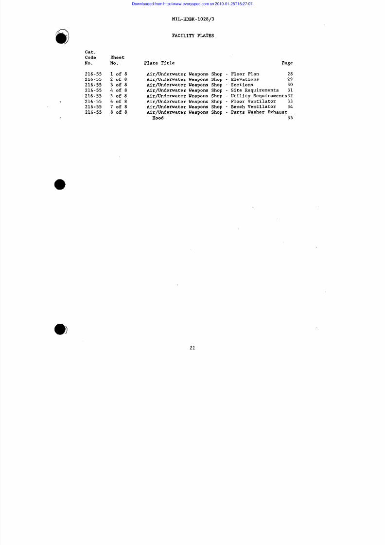
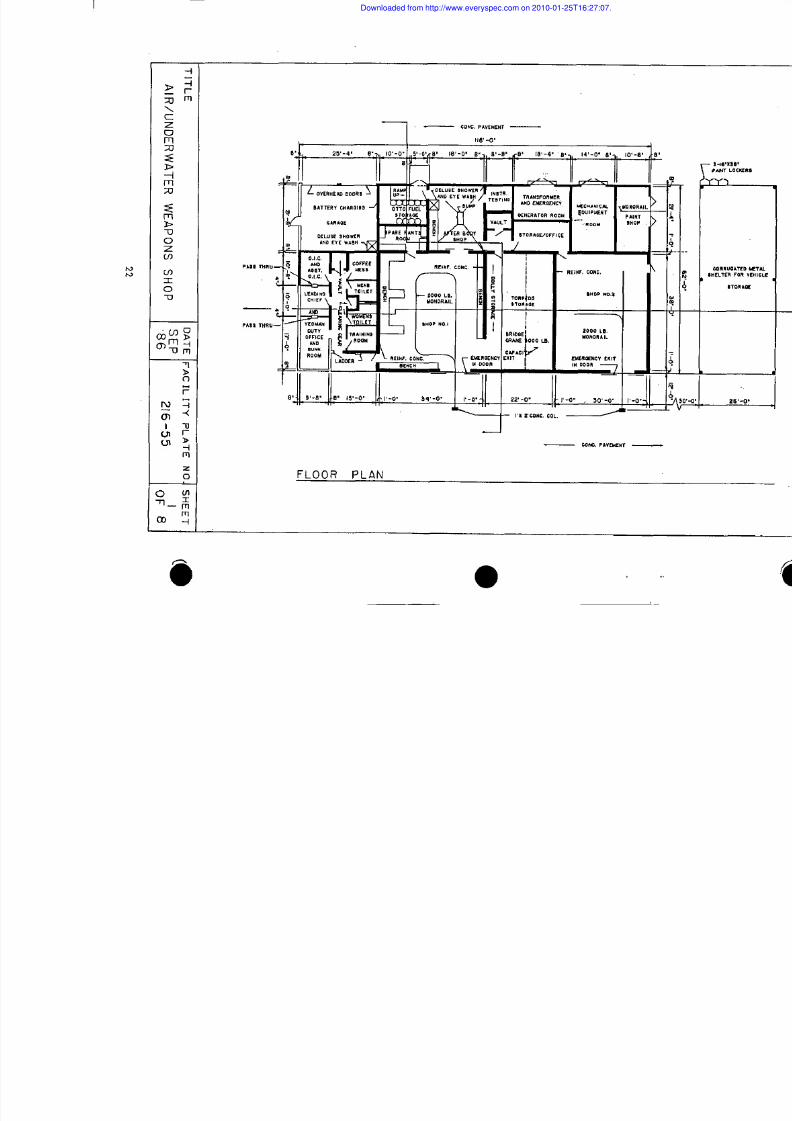
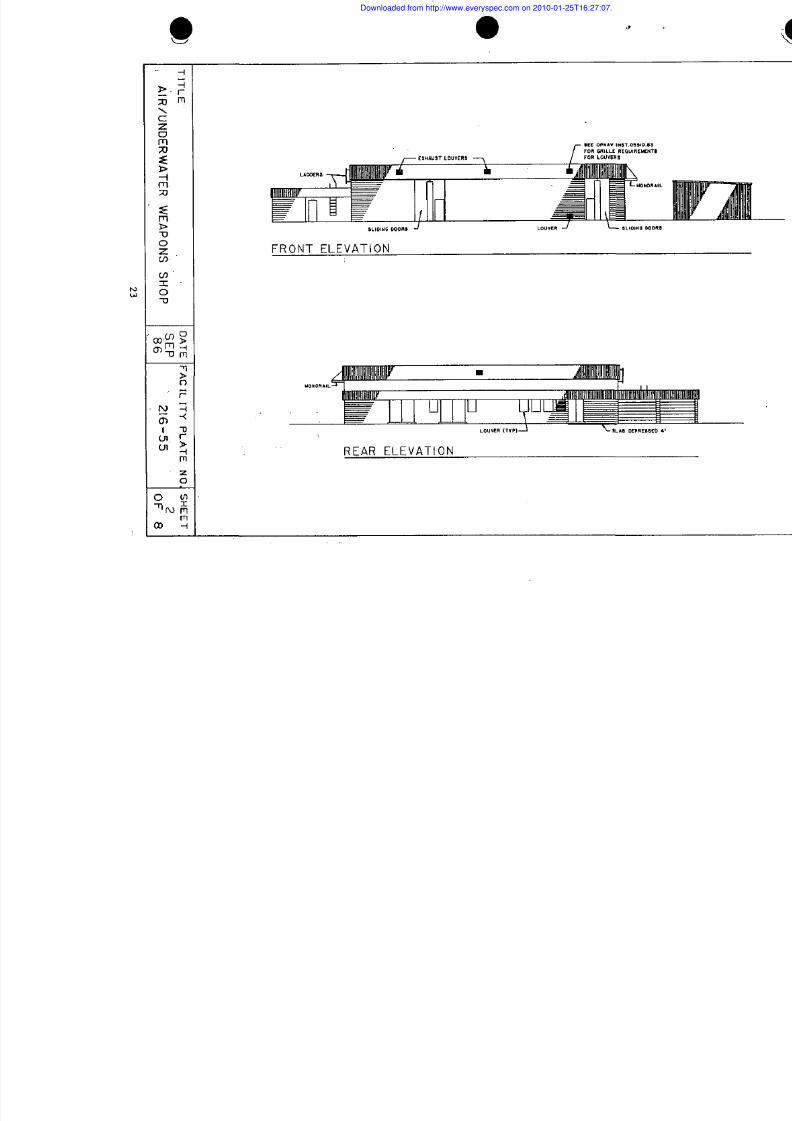
FACILITY PIATES
Plate Title Page
Air/Underwater Weapons Shop - Floor Plan 28
Air/Underwater Weapons Shop - Elevations 29Air/lJndenraterWeapons Shop - Sections 30
Air/Underwater Weapons Shop - Site Requirements 31
Air/Underwater Weapons Shop - Utility Requirements32
Air/Underwater Weapons Shop - Floor Ventilator 33
Air/Underwater Weapons Shop - Bench Ventilator 34
Air/Underwater Weapons Shop - Parts Washer Exhaust
Hood 35
21
Downloaded from http://www.everyspec.com on 2010-01-25T16:27:07.
8/8/2019 27064203 Department of DEFENSE Mil Hdbk 1028 3 Military Handbook Maintenance Facilities for Ammunition Explo…
http://slidepdf.com/reader/full/27064203-department-of-defense-mil-hdbk-1028-3-military-handbook-maintenance 31/43
.
I :::~:
m
s
IT
D
FALT
PA
N.S
ARU
W
W
O
S
S’8
2
5
0
8
22
Downloaded from http://www.everyspec.com on 2010-01-25T16:27:07.
8/8/2019 27064203 Department of DEFENSE Mil Hdbk 1028 3 Military Handbook Maintenance Facilities for Ammunition Explo…
http://slidepdf.com/reader/full/27064203-department-of-defense-mil-hdbk-1028-3-military-handbook-maintenance 32/43
z=a1
z
w
o
K
F
a
a
w
>
K
LdxIL
rT
D
FALT
PA
N.S
S
2655
ARU
W
W
O
S
8
0
8
23
Downloaded from http://www.everyspec.com on 2010-01-25T16:27:07.

8/8/2019 27064203 Department of DEFENSE Mil Hdbk 1028 3 Military Handbook Maintenance Facilities for Ammunition Explo…
http://slidepdf.com/reader/full/27064203-department-of-defense-mil-hdbk-1028-3-military-handbook-maintenance 33/43
,0
>
7
z
:
0
‘Z%
-MJ
F
1
o
,me
u
L
2
?
z
,0
z
“
‘“L
:
rT
D
FALT
PA
N.S
A
R
U
W
W
O
S
=
2
5
3
O
8
2
Downloaded from http://www.everyspec.com on 2010-01-25T16:27:07.
8/8/2019 27064203 Department of DEFENSE Mil Hdbk 1028 3 Military Handbook Maintenance Facilities for Ammunition Explo…
http://slidepdf.com/reader/full/27064203-department-of-defense-mil-hdbk-1028-3-military-handbook-maintenance 34/43
141L-HDBK.IO?R1?.–—-- ----, -
SUPERSEDES PARTOF DD-1291743
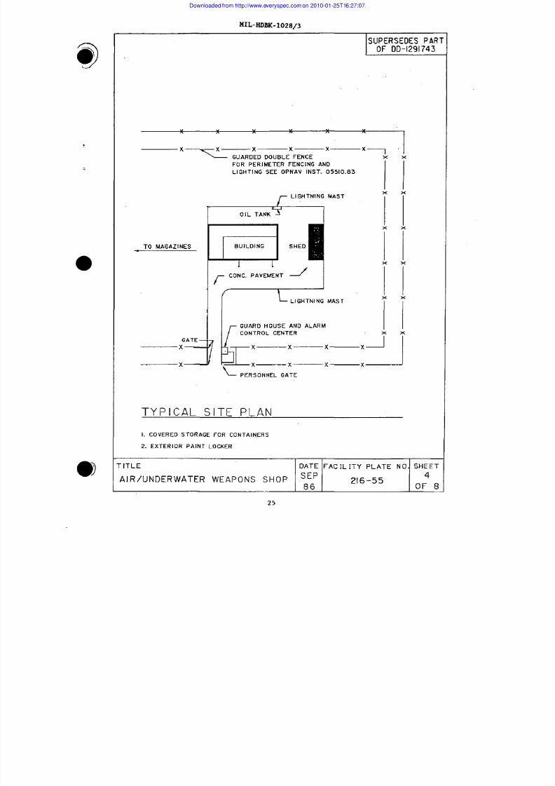
‘-—KI’—X—X-X-XIX ‘ .UARDED DOUBLE FENCE
FOR PERIMETER FENCING ANO
LIGHTING SEE OPNAV INST. 05510.83
LIGHTNING MASTx x
OIL TANK%
x x
TO MAGAZINES BUILOING SHEO
1 1x x
/-
CONC. PAVEMENT J
(
LIGHTNING MAST
x x
GUARO HOUSE AND ALARM
CONTROL CENTER
GATE —
x x— x— x— J’ x
x J
I_x x x xPERSONNEL GATE
TYPICAL SITE PLAN
1. COVERED STORAGE FOR CONTAINERS
2. EXTERIOR PAINT LOCXER
“ITLE DATE FACILITY PLATE NO. SHEET
AIR/UNDERWATER WEAPONS SHOP SEP216-55
4
86 OF 8
25
Downloaded from http://www.everyspec.com on 2010-01-25T16:27:07.
8/8/2019 27064203 Department of DEFENSE Mil Hdbk 1028 3 Military Handbook Maintenance Facilities for Ammunition Explo…
http://slidepdf.com/reader/full/27064203-department-of-defense-mil-hdbk-1028-3-military-handbook-maintenance 35/43
t41L-HDBK-1028/3
SUPERSEDES PARTOF DD-1291743
NOTES
PLUMBING REQUIREMENTS
COLD WATER 65 G.P. M.
HOT WATER
RECOVERY RATE(THRU 100” RISE] 60 G.P. Ii.
STORAGE 70 GAL.
THE ABOVE RATES DO NOT INCLUDE
REQUIREMENTS FOR FIRE PROTECTION
HEATING REQUIREMENTS (M BTU/HR)
INSIDE DESIGN TEMPERATURE 70” F
OUTSIDE DESIGN TEMPERATURE
-5°F +5°F +15” F +25” F—. — _504 432 367 ,302
AIR CONDITIONING REQUIREMENTS
SHOP SPACES
INSIDE DESIGN TEMPERATURE MIN. 70” F.D.B.
MAX. 40” F-. D.B.
INSIDE DESIGN HUMIDITY 40% R.H.
PERSONNEL SPACES
INSIDE DESIGN TEMPERATURE 78” F.D.B.
INSIDE OESIGN HUMIDITY 50% R.H.
COOLING LOAO IMBTU.HR) 492
ELECTRICAL REQUIREMENTS (KW)
L IGHTSCONNECTEO LOAD 72.0
ESTIMATED DEMAND 57.6
POWER
CONNECTED LOAD 41.8
ESTIMATED DEMAND 33.4
TOTAL
CONNECTED LOAD 113.8
ESTIMATED DEMAND 91.0
ADDITIONAL DEMAND FOR AIRCONDITIONING 41.0
AREAS
GROSS AREA INCLUOING MECHANICAL
EQUIPMENT ROOM 7,192 S.F.
VEHICLE SHED 1,550 S.F.
rlTLE
E
DATE FACILITY PLATE NO SHEET
SEPAIR/UNDERWATER WEAPONS SHOP 86 216-550: 8
26
@
/
Downloaded from http://www.everyspec.com on 2010-01-25T16:27:07.

8/8/2019 27064203 Department of DEFENSE Mil Hdbk 1028 3 Military Handbook Maintenance Facilities for Ammunition Explo…
http://slidepdf.com/reader/full/27064203-department-of-defense-mil-hdbk-1028-3-military-handbook-maintenance 36/43
MIL-HoBK-1028/3
@
“\
t
FLOOR VENTILATOR
I
h—z
f!
:
(
[
/
rITLE DATE FACILITY PLATE NO. SHEET
AIR/UNDERWATER WEAPONS SHOPSEP86 ‘
216-55 0::8
ELEVATION VIEW
NOT TO SCALE
MAX. PLENUM VELOCITY (1000 F. P.M.)
SLOT VELOCITY (MINI (2000 F. P.M.)
CAPTURE VELOCITY (150 F.P. M. AT 24”)
DUCT VELOCITY [MIN) (2000 F. P.M.)
AIR VOLUME (4167 C. F. M.)
27
Downloaded from http://www.everyspec.com on 2010-01-25T16:27:07.
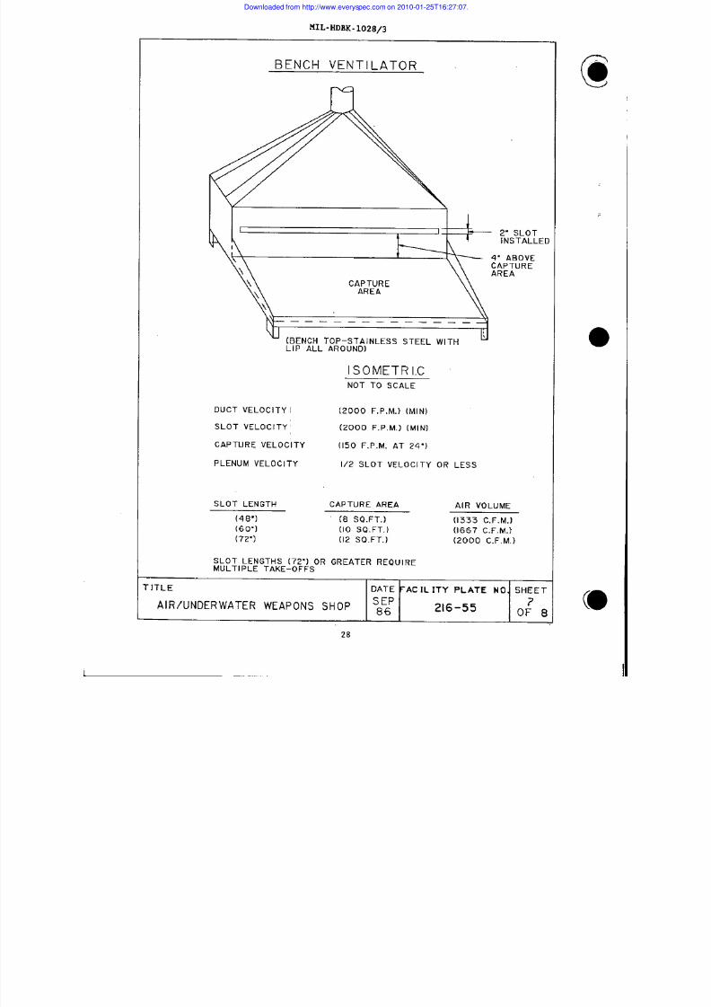
8/8/2019 27064203 Department of DEFENSE Mil Hdbk 1028 3 Military Handbook Maintenance Facilities for Ammunition Explo…
http://slidepdf.com/reader/full/27064203-department-of-defense-mil-hdbk-1028-3-military-handbook-maintenance 37/43
MIL-HDBK-I02Ejq—-r-
BENCH VENTILATOR
INSTALLED
CAPTURE
(BENCH TOP-STAINLESS STEEL WITHLIP ALL AROUNO)
ISOMETRICNOT TO SCALE
DUCT VELOCITY 1 (2000 F, P.M.) (MIN)
SLOT VELOCITY (2000 F. P.M.) (MIN)
CAPTURE VELOCITY (150 F.P. M. AT 24”)
PLENUM VELOCITY 1/2 SLOT VELOCITY OR LESS
SLOT LENGTH CAPTURE AREA AIR VOLUME
(48”1 (8 SQ.FT. ) (1333 C. F. M.)
(6o”l (10 SO. FT.) (1667 C. F. M.)
(72”) (I2 SO. FT.) (2000 C. F. M.)
SLOT LENGTHS [72”) OR GREATER REQUIREMULTIPLE TAKE-OFFS
r ITLE DATE FACILITY PLATE NO. SHEET
S EPAIR/UNDERWATER WEAPONS SHOP 86 216-55 0: 8
t
(028
Downloaded from http://www.everyspec.com on 2010-01-25T16:27:07.
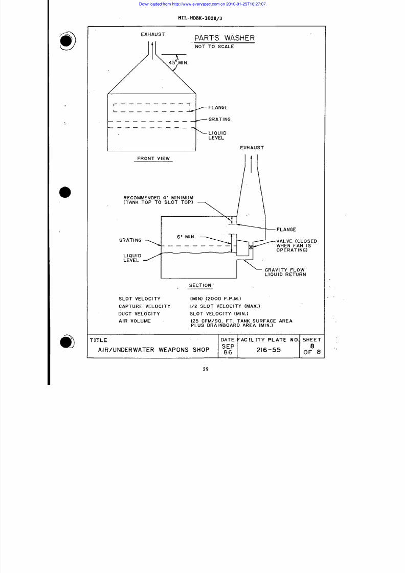
8/8/2019 27064203 Department of DEFENSE Mil Hdbk 1028 3 Military Handbook Maintenance Facilities for Ammunition Explo…
http://slidepdf.com/reader/full/27064203-department-of-defense-mil-hdbk-1028-3-military-handbook-maintenance 38/43
MIL-NDBK-1028/3
a)T
EXHAUST
PARTS WASHER‘“ NOT TO SCALE
r—— ——— —__7FLANGE
L————— ——— M -
— — — — — — — — -GRATING
.——. ——. — _ T
~LIOUIOLEVEL
EXHAUST
FRONT VIEW
RECOMMENOEO 4“ MINIMUM
[TANK TOP TO SLOT TOP)
\
— FLANGE
GRATING‘“:: ~ VALVE (CLOSED
— — =WHEN FAN ISOPERATING)
LIOUIDLEVEL
GRAVITY FLOWLIOUID RETURN
SECTION
SLOT VELOCITY (MIN) (2000 F. P.M.)
CAPTURE VELOCITY 1/2 SLOT VELOCITY (MAX. )
DUCT VELOCITY SLOT VELOCITY (MIN. )
AIR VOLUME 125 CFM/SO. FT. TANK SURFACE AREAPLUS DRAINBOARD AREA [MI N.)
rlTLE DATE FACILIT’f PLATE NO. SHEET
SEPAIR/UNDERWATER WEAPONS SHOP g~ 216-55
8OF 8
29
Downloaded from http://www.everyspec.com on 2010-01-25T16:27:07.
8/8/2019 27064203 Department of DEFENSE Mil Hdbk 1028 3 Military Handbook Maintenance Facilities for Ammunition Explo…
http://slidepdf.com/reader/full/27064203-department-of-defense-mil-hdbk-1028-3-military-handbook-maintenance 39/43
MIL-HDBK-1028/3
REFERENCES
@
,/
American Conference of Governmental Industrial Hygienists (ACGIH1. Bldg. D-5,
6500 Glenway, Cincinnati, OH 45211
Industrial Ventilation, Manual of Recommended Practice
Threshold Limit Values for Chemical Substances in the Work
Environment
American National Standards Institute (ANSI) Standards, 1430 Broadway, New
York, NY 10018
2358.01-81 Emergency Eyewash and Shower Equipment
Z9.04-85 Exhaust Systems - Abrasive Blasting
Operations - Ventilation and Safe Practices
Military Standards (MIL-STD) and Specifications fMlL-SPEC)-
MIL-STD-704 Aircraft Electric Power Characteristics
MIL-P-24441 General Specifications for Paint, Epoxy
Polyamide
Military Documents are available from the Commanding Officer, Publications
and Forms Center, 5801 Tabor Ave. , Philadelphia, PA 19120. Telephone:
AUTOVON (DOD only) 442-3321; Commercial 215/697-3321. TWX: 710-670-1685.
National Fire Protection Association (NFPA) Standards, Batterymarch Park,
Quincy, MA 02269
33 Spray Application Using Flammable and
Combustible Materials
70-87 National Electric Code
91 Blower and Exhaust Systerns
Naval Facilities Eneineerinc Command (NAVFACENGCOM) Documents
DM-1 Series Architecture
DM-1.01 Basic Architectural Requirements and Design
Considerations
DM-1.02 Materials and Building Components
DM-2 Series Structural Engineering
...
.,
30
Downloaded from http://www.everyspec.com on 2010-01-25T16:27:07.
8/8/2019 27064203 Department of DEFENSE Mil Hdbk 1028 3 Military Handbook Maintenance Facilities for Ammunition Explo…
http://slidepdf.com/reader/full/27064203-department-of-defense-mil-hdbk-1028-3-military-handbook-maintenance 40/43
--) DM-3 Series
DM-3.01
DM-3.03
DM-3.05
DM-3.1O
DM-4 Series
DM-4.06
DM-5
MIL-HDBK-1006/1
DM-7 Series
MIL-HDBK-1OO8
MIL-HDBK-1013/1
MIL-HDBK-102B/3
MIL-HDBK-1190
DM-28.04
DM-38.01
INST 4101.1
INST 5100.11
P-80, Volume I
P-272
P-309
P-355
P-397
MIL-HDBK-1028/3
Mechanical Engineering
Plumbing Systems
Heating, Ventilating, Air Conditioning and
Dehumidifying Systems
Compressed Air and Vacuum Systems
Noise and Vibration Control for Mechanical
Equipment (ARMY)
Electrical Engineering
Lightning and Cathodic Protection
Civil Engineering
Policy and Procedures for Construction
Drawings and Specification Preparation
Soil Mechanics, Foundations, and Earth
Struetures
Fire Protection for Facilities Engineering
Design and Construction
Physical Security of Land-based Facilities
Maintenance Facilities for Ammunition,
Explosives, and Toxins
Facility Planning and Design Guide
General Maintenance Facilities
Weight-Handling Equipment
Energy Budgets for New Facilities
Command Safety and Health Program
Facility Planning Criteria for Navy and
Marine “Corps Shore Installations
Definitive Designs for Naval Shore
Facilities ‘
‘ Color For Naval Shore Facilities
Seismic Design for Buildings
Structures to Resist the Effects of
Accidental Explosions
31
Downloaded from http://www.everyspec.com on 2010-01-25T16:27:07.
8/8/2019 27064203 Department of DEFENSE Mil Hdbk 1028 3 Military Handbook Maintenance Facilities for Ammunition Explo…
http://slidepdf.com/reader/full/27064203-department-of-defense-mil-hdbk-1028-3-military-handbook-maintenance 41/43
NFGS-09785
NAVAIRSYSCOM Publication
NAVAIR TM 16-1-’529
NAVMEDCOM Publication
NAVMEDCOMINST 6270.1
NAVSEASYSCOM Publications
OP-5
s634O-AA-MMA-O1O
OP 3565, Volume 11
OD 30393
NAVSUP Publication
INST 4570.23
OPNAV Instructions
INST 5510.lG
INST 5510.83
INST 5530.14A
MIL-HDBK-1028/3
Metallic-Type Conductive
Concrete Floor Finish
Technical Manual
and Spark-Resistant
@
<
Health Hazards
Ammunition and
of Otto Fuel 11
Explosives Ashore
Otto Fuel II, Safety, Storage, and Handling
Instructions
Electromagnetic Radiation Hazards (Hazards
to Ordnance)
Part I - (Hazards to Unclassified Ordnance
Systems)
Part II - (Hazards to Classified Ordnance
Systems)
Design Principles and Practices for
Controlling Hazards of Electromagnetic
Radiation to Ordnance (Hero Design Guide)
Recovery and Utilization of Precious Metals
Department of Navy Information and Personnel
Security Program Regulation
Navy Nuclear Weapon Security Manual
United States Navy Physical Security and
Loss Prevention Manual
Department of Defense activities may obtain copies of Design Manuals,
P-Publications, and Definitive Drawings from the Commanding Officer, Naval
Publications and Forms Center, 5801 Tabor Avenue, Philadelphia, PA 19120.
Department of Defense activities mu t use the 14ilitarv Standard
Re&is itioning and Issue Procedure (141STRIP), using ~he stock control number
obtained from NAVSUP Publication 2002.
32
Downloaded from http://www.everyspec.com on 2010-01-25T16:27:07.
8/8/2019 27064203 Department of DEFENSE Mil Hdbk 1028 3 Military Handbook Maintenance Facilities for Ammunition Explo…
http://slidepdf.com/reader/full/27064203-department-of-defense-mil-hdbk-1028-3-military-handbook-maintenance 42/43
MIL-HDBK-1028/3
>
Other Government agenties and commercial organizations may
Manuals, P-Publications, and Definitive Drawings from the
Documents, U.S. Government Printing Office, Washington, DC
procure Design
Superintendent of
20402.
Occupational Safety and Health Administration (OSHA) Standard, U.S.
Government Printing Office, Washington. DC 20402.
2040 Occupational Safety and Health Act
Manual, Regulations Construction
CUSTODIAN :
NAVY - YO
Standards
PREPARING ACTIVITY
NAVY - YD
PROJECT NO.
FACR-0221
33
Downloaded from http://www.everyspec.com on 2010-01-25T16:27:07.
8/8/2019 27064203 Department of DEFENSE Mil Hdbk 1028 3 Military Handbook Maintenance Facilities for Ammunition Explo…
http://slidepdf.com/reader/full/27064203-department-of-defense-mil-hdbk-1028-3-military-handbook-maintenance 43/43
STANDARDIZATION DOCUMENT IMPROVEMENT PROPOSAL
(Sss Inmuclions - Rswrss Sids)
DOCUMENT NUMBER S. DOCUMENT TITLE
MIL-HDE-1028/3 ~ FACIXFJ7ES I13RAMMUiiITIC!i,EXP~IVES AD TO= ;
.NAME OF SUBM1TTIN1 3 ORnANI ZATlON 4. TYPE OF ORGANIZATION (,Mv -s on.)
u VErdoor l
~ usEm
A00 t 3E” 6%(Sb ’u t , Ci l y, FS t aM .Z IP C-)
uMAN”,ACT”.,R
u OTHER ( Slm ,t i ,:-
PROB LEM AREAS
. Parw qh N. fnbor - Wc .rd ln#:
h R.w mhundd W ordlng :
c . R_n/Rodon.l . for Rac ommondat i o .:
,,
REMARKS,;
.. . . . . ..,.
. ~.,:, ,
,,. ,,. “ ’, ,’” , ,’
.!, ;: ,..
......... :,:
,.. , , . . . .. . . . .
,.:,,.. ~,.’, ,, ::
NAME 0.= 5UWITTER /b t , Ft i t , M I) - OPtEond b:w ORK ,TELEpHONE NUMSER U.=IU* .4ma
c +) - Olx (w l .1
@
q
Downloaded from http://www.everyspec.com on 2010-01-25T16:27:07.