2707-800, dtam plus operator interface module user manual · user manual dtam plus operator...
TRANSCRIPT

UserManual
DTAM PlusOperatorInterfaceModule
Catalog Nos. 2707-L8x,-L40x, -V40x
Allen-Bradley

1
Solid state equipment has operational characteristics differing from those ofelectromechanical equipment. “Safety Guidelines for the Application,Installation and Maintenance of Solid State Controls” (Publication SGI-1.1)describes some important differences between solid state equipment andhard–wired electromechanical devices. Because of this difference, and alsobecause of the wide variety of uses for solid state equipment, all personsresponsible for applying this equipment must satisfy themselves that eachintended application of this equipment is acceptable.
In no event will the Allen-Bradley Company be responsible or liable forindirect or consequential damages resulting from the use or application ofthis equipment.
The examples and diagrams in this manual are included solely for illustrativepurposes. Because of the many variables and requirements associated withany particular installation, the Allen-Bradley Company cannot assumeresponsibility or liability for actual use based on the examples and diagrams.
No patent liability is assumed by Allen-Bradley Company with respect to useof information, circuits, equipment, or software described in this manual.
Reproduction of the contents of this manual, in whole or in part, withoutwritten permission of the Allen-Bradley Company is prohibited.
Throughout this manual we use notes to make you aware of safetyconsiderations.
!ATTENTION: Identifies information about practices orcircumstances that can lead to personal injury or death, propertydamage, or economic loss.
Attentions help you:
• identify a hazard• avoid the hazard• recognize the consequences
Important: Identifies information that is especially important for successfulapplication and understanding of the product.
PLC, PLC–2, PLC–3, PLC–5 are registered trademarks of Allen-Bradley Company, Inc.SLC is a trademark of Allen-Bradley Company, Inc
Important User Information

DTAM Plus Operator Interface ModuleUser Manual
Table of Contents
i
Preface
Objectives P–1. . . . . . . . . . . . . . . . . . . . . . . . . . . . . . . . . . . . . . . . . . . . . . . . . Chapter Contents P–1. . . . . . . . . . . . . . . . . . . . . . . . . . . . . . . . . . . . . . . . . . . Intended Audience P–2. . . . . . . . . . . . . . . . . . . . . . . . . . . . . . . . . . . . . . . . . . . Package Contents P–2. . . . . . . . . . . . . . . . . . . . . . . . . . . . . . . . . . . . . . . . . . . Conventions P–2. . . . . . . . . . . . . . . . . . . . . . . . . . . . . . . . . . . . . . . . . . . . . . . Related Publications P–3. . . . . . . . . . . . . . . . . . . . . . . . . . . . . . . . . . . . . . . . .
Chapter 1
Objectives 1–1. . . . . . . . . . . . . . . . . . . . . . . . . . . . . . . . . . . . . . . . . . . . . . . . . General Information 1–1. . . . . . . . . . . . . . . . . . . . . . . . . . . . . . . . . . . . . . . . . . Description 1–2. . . . . . . . . . . . . . . . . . . . . . . . . . . . . . . . . . . . . . . . . . . . . . . . Keypad 1–4. . . . . . . . . . . . . . . . . . . . . . . . . . . . . . . . . . . . . . . . . . . . . . . . . . . DIP Switches 1–5. . . . . . . . . . . . . . . . . . . . . . . . . . . . . . . . . . . . . . . . . . . . . . . Communication Ports 1–6. . . . . . . . . . . . . . . . . . . . . . . . . . . . . . . . . . . . . . . . . Communication Ports 1–7. . . . . . . . . . . . . . . . . . . . . . . . . . . . . . . . . . . . . . . . . RS-232 Communications 1–8. . . . . . . . . . . . . . . . . . . . . . . . . . . . . . . . . . . . . . RS-485 Communications 1–9. . . . . . . . . . . . . . . . . . . . . . . . . . . . . . . . . . . . . . Remote I/O Communications 1–10. . . . . . . . . . . . . . . . . . . . . . . . . . . . . . . . . . . Default Settings 1–11. . . . . . . . . . . . . . . . . . . . . . . . . . . . . . . . . . . . . . . . . . . . .
Operating System 1–11. . . . . . . . . . . . . . . . . . . . . . . . . . . . . . . . . . . . . . . . . DIP Switch Settings 1–11. . . . . . . . . . . . . . . . . . . . . . . . . . . . . . . . . . . . . . . . Operating Parameters 1–12. . . . . . . . . . . . . . . . . . . . . . . . . . . . . . . . . . . . . .
DTAM Programming Software (DPS) 1–12. . . . . . . . . . . . . . . . . . . . . . . . . . . . . .
Chapter 2
Objectives 2–1. . . . . . . . . . . . . . . . . . . . . . . . . . . . . . . . . . . . . . . . . . . . . . . . . Power Source 2–1. . . . . . . . . . . . . . . . . . . . . . . . . . . . . . . . . . . . . . . . . . . . . . Applying Power 2–2. . . . . . . . . . . . . . . . . . . . . . . . . . . . . . . . . . . . . . . . . . . . . Powerup Sequence 2–3. . . . . . . . . . . . . . . . . . . . . . . . . . . . . . . . . . . . . . . . . .
Powerup Sequence (DIP Switch SW-1 ON) 2–3. . . . . . . . . . . . . . . . . . . . . . . Powerup Sequence (DIP Switch SW-1 OFF) 2–4. . . . . . . . . . . . . . . . . . . . . .
Upload / Download DIP Switch Settings 2–5. . . . . . . . . . . . . . . . . . . . . . . . . . . . Upload / Download RS-232 Connections 2–6. . . . . . . . . . . . . . . . . . . . . . . . . . . Upload / DownloadRS-485 Connections 2–7. . . . . . . . . . . . . . . . . . . . . . . . . . . Computer Setup 2–7. . . . . . . . . . . . . . . . . . . . . . . . . . . . . . . . . . . . . . . . . . . . Downloading an Application 2–8. . . . . . . . . . . . . . . . . . . . . . . . . . . . . . . . . . . . Uploading an Application 2–13. . . . . . . . . . . . . . . . . . . . . . . . . . . . . . . . . . . . . .
Chapter 3
Objectives 3–1. . . . . . . . . . . . . . . . . . . . . . . . . . . . . . . . . . . . . . . . . . . . . . . . . Function Key Menu 3–2. . . . . . . . . . . . . . . . . . . . . . . . . . . . . . . . . . . . . . . . . .
DTAM Plus Overview
Loading an Application
Using the Function Menu

DTAM Plus Operator Interface ModuleUser Manual
Table of Contents
ii
Resetting the DTAM Plus 3–3. . . . . . . . . . . . . . . . . . . . . . . . . . . . . . . . . . . . . . To reset the DTAM Plus: 3–3. . . . . . . . . . . . . . . . . . . . . . . . . . . . . . . . . . .
Setting Communication Port Parameters 3–4. . . . . . . . . . . . . . . . . . . . . . . . . . . Baud Rate 3–4. . . . . . . . . . . . . . . . . . . . . . . . . . . . . . . . . . . . . . . . . . . . . Data Bits 3–4. . . . . . . . . . . . . . . . . . . . . . . . . . . . . . . . . . . . . . . . . . . . . . Parity 3–4. . . . . . . . . . . . . . . . . . . . . . . . . . . . . . . . . . . . . . . . . . . . . . . .
Displaying Remote I/O Port Parameters 3–5. . . . . . . . . . . . . . . . . . . . . . . . . . . To display Remote I/O communication parameters: 3–5. . . . . . . . . . . . . . . . Baud Rate 3–5. . . . . . . . . . . . . . . . . . . . . . . . . . . . . . . . . . . . . . . . . . . . . Rack Size 3–5. . . . . . . . . . . . . . . . . . . . . . . . . . . . . . . . . . . . . . . . . . . . . Last Rack 3–6. . . . . . . . . . . . . . . . . . . . . . . . . . . . . . . . . . . . . . . . . . . . . Rack Number 3–6. . . . . . . . . . . . . . . . . . . . . . . . . . . . . . . . . . . . . . . . . . Module Group 3–6. . . . . . . . . . . . . . . . . . . . . . . . . . . . . . . . . . . . . . . . . . Reset 3–6. . . . . . . . . . . . . . . . . . . . . . . . . . . . . . . . . . . . . . . . . . . . . . . .
Setting Printer Port Parameters 3–7. . . . . . . . . . . . . . . . . . . . . . . . . . . . . . . . . . Baud Rate 3–7. . . . . . . . . . . . . . . . . . . . . . . . . . . . . . . . . . . . . . . . . . . . . Data Bits 3–7. . . . . . . . . . . . . . . . . . . . . . . . . . . . . . . . . . . . . . . . . . . . . . Parity 3–8. . . . . . . . . . . . . . . . . . . . . . . . . . . . . . . . . . . . . . . . . . . . . . . . Handshake 3–8. . . . . . . . . . . . . . . . . . . . . . . . . . . . . . . . . . . . . . . . . . . . Line Feed 3–8. . . . . . . . . . . . . . . . . . . . . . . . . . . . . . . . . . . . . . . . . . . . . Port Enable 3–8. . . . . . . . . . . . . . . . . . . . . . . . . . . . . . . . . . . . . . . . . . . .
Enabling Screen Prints 3–9. . . . . . . . . . . . . . . . . . . . . . . . . . . . . . . . . . . . . . . . Setting the Clock/Calendar 3–10. . . . . . . . . . . . . . . . . . . . . . . . . . . . . . . . . . . . . Adjusting the Display Contrast (LCD versions only) 3–11. . . . . . . . . . . . . . . . . . . Adjusting the Display Brightness 3–12. . . . . . . . . . . . . . . . . . . . . . . . . . . . . . . . . Enabling Simulate Mode 3–13. . . . . . . . . . . . . . . . . . . . . . . . . . . . . . . . . . . . . . . Enabling Terminal Mode 3–14. . . . . . . . . . . . . . . . . . . . . . . . . . . . . . . . . . . . . . .
To set parameters for Terminal Mode: 3–14. . . . . . . . . . . . . . . . . . . . . . . . . Half Duplex 3–14. . . . . . . . . . . . . . . . . . . . . . . . . . . . . . . . . . . . . . . . . . . . Line Feed Enable 3–15. . . . . . . . . . . . . . . . . . . . . . . . . . . . . . . . . . . . . . . . Cursor Enable 3–15. . . . . . . . . . . . . . . . . . . . . . . . . . . . . . . . . . . . . . . . . .
Entering a New Master Security Code 3–16. . . . . . . . . . . . . . . . . . . . . . . . . . . . . To enter a new Master Security code: 3–16. . . . . . . . . . . . . . . . . . . . . . . . . Master Security code operation: 3–17. . . . . . . . . . . . . . . . . . . . . . . . . . . . .
Using Scaling 3–18. . . . . . . . . . . . . . . . . . . . . . . . . . . . . . . . . . . . . . . . . . . . . . Accessing the Point/Access Display Function 3–19. . . . . . . . . . . . . . . . . . . . . . . . Accessing Test Functions 3–20. . . . . . . . . . . . . . . . . . . . . . . . . . . . . . . . . . . . . .
Chapter 4
Chapter Objectives 4–1. . . . . . . . . . . . . . . . . . . . . . . . . . . . . . . . . . . . . . . . . . DIP Switch Setting 4–1. . . . . . . . . . . . . . . . . . . . . . . . . . . . . . . . . . . . . . . . . . . Application Documentation 4–1. . . . . . . . . . . . . . . . . . . . . . . . . . . . . . . . . . . . . Screen Types 4–2. . . . . . . . . . . . . . . . . . . . . . . . . . . . . . . . . . . . . . . . . . . . . .
Running Applications

DTAM Plus Operator Interface ModuleUser Manual
Table of Contents
iii
Screen Navigation 4–2. . . . . . . . . . . . . . . . . . . . . . . . . . . . . . . . . . . . . . . . . . . Screen Links 4–2. . . . . . . . . . . . . . . . . . . . . . . . . . . . . . . . . . . . . . . . . . . . . Advisor Option 4–2. . . . . . . . . . . . . . . . . . . . . . . . . . . . . . . . . . . . . . . . . . . .
Menu and Sub-Menu Screens 4–3. . . . . . . . . . . . . . . . . . . . . . . . . . . . . . . . . . . Main Menu 4–3. . . . . . . . . . . . . . . . . . . . . . . . . . . . . . . . . . . . . . . . . . . . . . Sub-Menus 4–3. . . . . . . . . . . . . . . . . . . . . . . . . . . . . . . . . . . . . . . . . . . . . .
Security Screens 4–3. . . . . . . . . . . . . . . . . . . . . . . . . . . . . . . . . . . . . . . . . . . . Data Display Screens 4–4. . . . . . . . . . . . . . . . . . . . . . . . . . . . . . . . . . . . . . . . Bar Graph Screens 4–4. . . . . . . . . . . . . . . . . . . . . . . . . . . . . . . . . . . . . . . . . . Data Entry Screens 4–4. . . . . . . . . . . . . . . . . . . . . . . . . . . . . . . . . . . . . . . . . . ASCII Input 4–5. . . . . . . . . . . . . . . . . . . . . . . . . . . . . . . . . . . . . . . . . . . . . . . . Recipe Screens 4–6. . . . . . . . . . . . . . . . . . . . . . . . . . . . . . . . . . . . . . . . . . . . . Alarm Screens 4–6. . . . . . . . . . . . . . . . . . . . . . . . . . . . . . . . . . . . . . . . . . . . . .
Chapter 5
Objectives 5–1. . . . . . . . . . . . . . . . . . . . . . . . . . . . . . . . . . . . . . . . . . . . . . . . . Safety Guidelines 5–1. . . . . . . . . . . . . . . . . . . . . . . . . . . . . . . . . . . . . . . . . . . Operating Environment 5–2. . . . . . . . . . . . . . . . . . . . . . . . . . . . . . . . . . . . . . . Enclosures 5–3. . . . . . . . . . . . . . . . . . . . . . . . . . . . . . . . . . . . . . . . . . . . . . . . Equipment Required 5–3. . . . . . . . . . . . . . . . . . . . . . . . . . . . . . . . . . . . . . . . . Clearances 5–3. . . . . . . . . . . . . . . . . . . . . . . . . . . . . . . . . . . . . . . . . . . . . . . . Mounting Dimensions 5–4. . . . . . . . . . . . . . . . . . . . . . . . . . . . . . . . . . . . . . . . . Cutout Template 5–5. . . . . . . . . . . . . . . . . . . . . . . . . . . . . . . . . . . . . . . . . . . . Installation 5–6. . . . . . . . . . . . . . . . . . . . . . . . . . . . . . . . . . . . . . . . . . . . . . . . Connecting Power 5–7. . . . . . . . . . . . . . . . . . . . . . . . . . . . . . . . . . . . . . . . . . .
Chapter 6
Chapter Objectives 6–1. . . . . . . . . . . . . . . . . . . . . . . . . . . . . . . . . . . . . . . . . . Wiring Guidelines 6–1. . . . . . . . . . . . . . . . . . . . . . . . . . . . . . . . . . . . . . . . . . . Connecting RS-232 Devices 6–2. . . . . . . . . . . . . . . . . . . . . . . . . . . . . . . . . . . . Connecting RS-485 Devices 6–3. . . . . . . . . . . . . . . . . . . . . . . . . . . . . . . . . . . . Connecting Remote I/O Devices 6–5. . . . . . . . . . . . . . . . . . . . . . . . . . . . . . . . . Communicating with a Logic Controller 6–6. . . . . . . . . . . . . . . . . . . . . . . . . . . . RS-232 or RS-422 Communications With a PLC-5 6–7. . . . . . . . . . . . . . . . . . . .
DTAM Plus 6–7. . . . . . . . . . . . . . . . . . . . . . . . . . . . . . . . . . . . . . . . . . . . PLC-5 6–7. . . . . . . . . . . . . . . . . . . . . . . . . . . . . . . . . . . . . . . . . . . . . . . .
RS-232 Communications with an SLC 5/03, -5/04 6–8. . . . . . . . . . . . . . . . . . . . . DTAM Plus 6–8. . . . . . . . . . . . . . . . . . . . . . . . . . . . . . . . . . . . . . . . . . . . SLC 5/03, 5/04 6–8. . . . . . . . . . . . . . . . . . . . . . . . . . . . . . . . . . . . . . . . .
DH-485 Communications with an SLC 500 or Network 6–9. . . . . . . . . . . . . . . . . DTAM Plus 6–9. . . . . . . . . . . . . . . . . . . . . . . . . . . . . . . . . . . . . . . . . . . . SLC 5/03, 5/04 6–10. . . . . . . . . . . . . . . . . . . . . . . . . . . . . . . . . . . . . . . . .
RS-232 Communications with a MicroLogix 1000 6–10. . . . . . . . . . . . . . . . . . . . .
Installation
CommunicationConnections and Setup

DTAM Plus Operator Interface ModuleUser Manual
Table of Contents
iv
RS-485 Communications with a MicroLogix 1000 6–11. . . . . . . . . . . . . . . . . . . . . DH-485 Communications with a MicroLogix 1000 6–12. . . . . . . . . . . . . . . . . . . . . Using ASCII Input 6–13. . . . . . . . . . . . . . . . . . . . . . . . . . . . . . . . . . . . . . . . . . .
Chapter 7
Chapter Objectives 7–1. . . . . . . . . . . . . . . . . . . . . . . . . . . . . . . . . . . . . . . . . . Troubleshooting Recommendations 7–1. . . . . . . . . . . . . . . . . . . . . . . . . . . . . . Equipment Required 7–1. . . . . . . . . . . . . . . . . . . . . . . . . . . . . . . . . . . . . . . . . Common Operating Problems 7–2. . . . . . . . . . . . . . . . . . . . . . . . . . . . . . . . . . . Error Messages 7–2. . . . . . . . . . . . . . . . . . . . . . . . . . . . . . . . . . . . . . . . . . . . . Communication Error Codes 7–4. . . . . . . . . . . . . . . . . . . . . . . . . . . . . . . . . . . . Using the Test Functions 7–5. . . . . . . . . . . . . . . . . . . . . . . . . . . . . . . . . . . . . . DIP Switch Test 7–6. . . . . . . . . . . . . . . . . . . . . . . . . . . . . . . . . . . . . . . . . . . . . Display Test 7–7. . . . . . . . . . . . . . . . . . . . . . . . . . . . . . . . . . . . . . . . . . . . . . . Keyboard Test 7–8. . . . . . . . . . . . . . . . . . . . . . . . . . . . . . . . . . . . . . . . . . . . . . Comm Port Test 7–9. . . . . . . . . . . . . . . . . . . . . . . . . . . . . . . . . . . . . . . . . . . . . Printer Port Test 7–10. . . . . . . . . . . . . . . . . . . . . . . . . . . . . . . . . . . . . . . . . . . . . Display Control Test 7–11. . . . . . . . . . . . . . . . . . . . . . . . . . . . . . . . . . . . . . . . . . RAM Test 7–12. . . . . . . . . . . . . . . . . . . . . . . . . . . . . . . . . . . . . . . . . . . . . . . . . System Memory Test 7–13. . . . . . . . . . . . . . . . . . . . . . . . . . . . . . . . . . . . . . . . . Program File Test 7–14. . . . . . . . . . . . . . . . . . . . . . . . . . . . . . . . . . . . . . . . . . . Clock/Calendar Test 7–15. . . . . . . . . . . . . . . . . . . . . . . . . . . . . . . . . . . . . . . . . . TXEN Test 7–16. . . . . . . . . . . . . . . . . . . . . . . . . . . . . . . . . . . . . . . . . . . . . . . . Cleaning the Display Window 7–17. . . . . . . . . . . . . . . . . . . . . . . . . . . . . . . . . . .
Appendix A
Agency Ratings A–2. . . . . . . . . . . . . . . . . . . . . . . . . . . . . . . . . . . . . . . . . . . . . European Union Directive Compliance A–3. . . . . . . . . . . . . . . . . . . . . . . . . . . . .
Appendix B
DTAM Plus Cables B–1. . . . . . . . . . . . . . . . . . . . . . . . . . . . . . . . . . . . . . . . . . . Catalog No. 2707-NC2 B–1. . . . . . . . . . . . . . . . . . . . . . . . . . . . . . . . . . . . . . Catalog No. 2707-NC3 B–2. . . . . . . . . . . . . . . . . . . . . . . . . . . . . . . . . . . . . . Catalog No. 2707-NC4 B–2. . . . . . . . . . . . . . . . . . . . . . . . . . . . . . . . . . . . . . Catalog No. 2707-NC6 B–3. . . . . . . . . . . . . . . . . . . . . . . . . . . . . . . . . . . . . . Catalog No. 2707-NC10 B–4. . . . . . . . . . . . . . . . . . . . . . . . . . . . . . . . . . . . . Catalog No. 1747-CP3 B–4. . . . . . . . . . . . . . . . . . . . . . . . . . . . . . . . . . . . . . DTAM Plus RS-232 Printer Port Cable B–6. . . . . . . . . . . . . . . . . . . . . . . . . . .
Appendix C
Objectives C–1. . . . . . . . . . . . . . . . . . . . . . . . . . . . . . . . . . . . . . . . . . . . . . . . . Accessing Special Functions C–2. . . . . . . . . . . . . . . . . . . . . . . . . . . . . . . . . . .
Troubleshooting andMaintenance
Specifications
DTAM Plus Cable Diagrams
Special ControllerFunctions

DTAM Plus Operator Interface ModuleUser Manual
Table of Contents
v
Using the P-A/D Function C–3. . . . . . . . . . . . . . . . . . . . . . . . . . . . . . . . . . . . . . Reading Controller Input and Output Files C–4. . . . . . . . . . . . . . . . . . . . . . . . . . Reading / Writing Controller Status Files C–5. . . . . . . . . . . . . . . . . . . . . . . . . . . Reading / Writing Controller Bit and Integer Files C–6. . . . . . . . . . . . . . . . . . . . . Reading / Writing Controller Timer Files C–7. . . . . . . . . . . . . . . . . . . . . . . . . . . . Reading / Writing Controller Counter Files C–8. . . . . . . . . . . . . . . . . . . . . . . . . . Reading / Writing Controller Control Files C–9. . . . . . . . . . . . . . . . . . . . . . . . . . . Reading / Writing Floating Point Files C–10. . . . . . . . . . . . . . . . . . . . . . . . . . . . . Reading / Writing Controller ASCII Files C–11. . . . . . . . . . . . . . . . . . . . . . . . . . . . Reading / Writing Controller BCD Files C–12. . . . . . . . . . . . . . . . . . . . . . . . . . . . Reading / Writing Controller Block Transfer Files C–13. . . . . . . . . . . . . . . . . . . . . Reading / Writing Controller Message Files C–14. . . . . . . . . . . . . . . . . . . . . . . . . Reading / Writing PID Files C–15. . . . . . . . . . . . . . . . . . . . . . . . . . . . . . . . . . . . . Reading / Writing SFC Files C–16. . . . . . . . . . . . . . . . . . . . . . . . . . . . . . . . . . . . Reading Controller ASCII String Files C–17. . . . . . . . . . . . . . . . . . . . . . . . . . . . . Using the Mode Function C–19. . . . . . . . . . . . . . . . . . . . . . . . . . . . . . . . . . . . . .
SLC Controllers C–19. . . . . . . . . . . . . . . . . . . . . . . . . . . . . . . . . . . . . . . . . PLC Controllers C–19. . . . . . . . . . . . . . . . . . . . . . . . . . . . . . . . . . . . . . . . .
Using the Memory Transfer Function C–20. . . . . . . . . . . . . . . . . . . . . . . . . . . . . . SLC Controllers C–20. . . . . . . . . . . . . . . . . . . . . . . . . . . . . . . . . . . . . . . . . PLC Controllers C–20. . . . . . . . . . . . . . . . . . . . . . . . . . . . . . . . . . . . . . . . .
Using the Clear Fault Function C–21. . . . . . . . . . . . . . . . . . . . . . . . . . . . . . . . . .
Appendix D
ASCII Transmission Characters D–1. . . . . . . . . . . . . . . . . . . . . . . . . . . . . . . . . ASCII Display Characters D–2. . . . . . . . . . . . . . . . . . . . . . . . . . . . . . . . . . . . . .
Appendix E
Terminal Mode
DTAM Plus MountingTemplate

A–B
Preface
P–1
Using this Manual
This chapter provides an overview of this manual. It covers:
• Chapter contents
• Intended audience
• Package contents
• Conventions
• Related publications
The manual contains the following chapters:
Chapter Title Purpose
Preface Using this Manual Provides an overview of the manual.
1 DTAM Plus Overview Contains a description of the DTAM Plusand accessory devices.
2 Loading an Application
Describes how to apply power andtransfer applications between thecomputer running the DPS Software andthe DTAM Plus.
3 Using the Function MenuDescribes how to access and use theDTAM Plus Function menu to performterminal operations.
4 Running ApplicationsDescribes the basic screen types andoperating procedures that are common tomost applications.
5 InstallationProvides procedures for mounting theDTAM Plus. Also provided are wiringinstructions and recommendations.
6 Communication Connections and Setup
Describes RS-232, RS-485 and RemoteI/O connections. Setup guidelines areprovided for SLC and PLC controllers.
7 Troubleshooting and Maintenance
Provides assistance in identifying and correcting common operatingproblems. Cleaning recommendationsare also provided.
Appendix A SpecificationsProvides the specifications, agencyratings, and European Union DirectiveCompliance.
Appendix B DTAM Plus Cable Diagrams Provides the cable diagrams for theDTAM Plus.
Appendix C Special Controller Functions Provides the special controller functions.
Appendix D Terminal Mode Provides the characters when the DTAMPlus is in terminal Mode.
Appendix E DTAM Plus MountingTemplate
Provides a mounting template for theDTAM Plus.
Objectives
Chapter Contents

Preface
P–2
No special knowledge is required to operate the DTAM Plus. If you areinstalling the DTAM Plus, you must be familiar with standard panel cutoutand installation techniques. If wiring the DTAM Plus, you must be familiarwith electrical codes in your area (see inside front cover).
You should be familiar with the DTAM Programming Software. See relatedpublications.
The DTAM Plus shipping box contains:
DTAM Plus User Manual(Catalog No. 2707-800)
Mounting Nuts (8)(2 Spare)
DIP Switch Cover
European Type GMDFuses and Holders
This manual uses the following conventions:
• Keys that you press on the DTAM Plus are enclosed in brackets [ ].For example: [NEXT] refers to the NEXT key on the DTAM Plus.
• References to menus are initial cap followed by the word Menu.For example: Special Menu, Main Menu, Other Menu
• All DTAM Plus displays are shown inside a rectangular box.
1 C-Port 5 Special2 P-Port 6 Term3 Clk/Cal 7 Test4 Reset 8 Other
Conventions
Intended Audience
Package Contents

Preface
P–3
You may want to refer to the following publications for additional reference.
DTAM Plus Publications
Publication Number Title
2707-801 August 98 or Later DTAM Programming Software Programming Manual (Series H or later Software)
Wiring Publications
1770-6.2.2 Data Highway / Data Highway Plus / Data Highway-485 Cable Installation Manual
1770-4.1 Programmable Controller Wiring and Grounding Guidelines
SLC Publications
Publication Number Title
1747-6.21 SLC 500 Fixed Hardware StyleInstallation and Operation Manual
1747-6.2 SLC 500 Modular Hardware StyleInstallation and Operation Manual
1746-6.1 SLC 500 BASIC ModuleDesign and Integration Manual
1746-6.3 SLC 500 BASICLanguage Reference Manual
1746-6.2 SLC 500 BASICDevelopment Software Programming Manual
1747-6.6 Remote I/O Scanner User Manual
1747-6.15 SLC 500 and MicroLogix Reference Manual
PLC-5 Publications
Publication Number Title
1785-6.2.1 1785 PLC-5 Programmable Controllers Design Manual
1785-6.1 PLC-5 Instruction Set Reference
1785-6.6.1 PLC-5 Family Programmable Controllers HardwareInstallation Manual
1785-7.1 PLC-5 Programmable Controllers Quick Reference
MicroLogix Publications
Publication Number Title
1747-6.15 SLC 500 and MicroLogix Reference Manual
1761-6.3 MicroLogix 1000 User Manual
1761-6.2.1 MicroLogix 1000 Quick Reference Guide
Related Publications

A–B 1Chapter
1–1
DTAM Plus Overview
This chapter describes the DTAM Plus and accessories.
Section Page
General Information 1–1
Description 1–2
Keypad 1–4
DIP Switches 1–5
Communication Ports 1–6
RS-232 Communications 1–8
RS-485 Communications 1–9
Remote I/O Communications 1–10
Default Settings 1–11
DTAM Plus Programming Software (DPS) 1–12
Product Options and Accessories 1–13
The DTAM Plus interfaces with the Allen-Bradley PLC and SLC controllerproduct lines. The DTAM Plus allows operators to monitor and manipulateprocess data on the plant floor.
RS-485 (DH-485), RS-232 / RS-422 (DF1) or Remote I/O Options.Connect the DTAM Plus to the SLC family of processors via DH485, innetwork or point-to-point modes or Remote I/O through a 1747-SN scanner.Connect to the PLC family using Remote I/O or RS-232 / RS-422 DF1through Channel 0 of PLC-5 processors.
8K or 40K Memory Capability. Supports up to 50 or 244 screens of data.
Recipe Operations. Recipe type functions allow operators to quicklymodify blocks of data. Download data to a maximum of 10 non-sequentialregister addresses per screen. Link multiple recipe screens to download datato more than 10 addresses.
Real Time Clock. 40K versions allow time stamping of critical reports anddisplayed data.
Point-Access/Display Function. Allows you to monitor or modify data filesin SLC or PLC controllers. Use this function to setup and debug applicationprograms.
ASCII Input Capability. 40K versions allow the input of ASCII data, suchas decoded bar code data, through the RS-232 printer port.
PLC or SLC Controlled Screen Changes. Controllers can both monitorand change the displayed screen.
Objectives
General Information

Chapter 1DTAM Plus OverView
1–2
The front panel of the DTAM Plus terminal is shown below.
Figure 1.1DTAM Plus (front view)
Power Connector
LED Indicators
Communications Port(s)
Display
DisplayThe 4 line by 20 character display uses either a Liquid Crystal Display(LCD) with LED backlighting or a Vacuum Fluorescent Display (VFD).
You can adjust both the contrast and backlight levels on LCD displays usingthe keypad. You can only adjust brightness on VFD displays.
KeypadThe keypad is a sealed unit with 25 tactile feedback keys. The VFD versiondoes not include the half moon brightness key so has 24 keys. The keys arecolor coded for easy identification of key functions. The keypad is designedfor hand operation. Using any other object or tool may damage the overlayor key.
LED IndicatorsThe front panel of the DTAM Plus has three indicators.
LED Indicator Color Indication
RUN Green Indicates proper operation of the DTAM Plus.
ALARM Red Indicates an alarm condition. The LED flashes on and offuntil the alarm is acknowledged.
Function (F) Key Yellow Indicates the F (Function) key is active.
Note: DIP Switch SW-4 enables the F key.
Description

Chapter 1DTAM Plus Overview
1–3
Figure 1.2DTAM Plus (back view)
DIP Switch(Behind Removable
Cover)
Power Connector
FusesCommunication Ports
Communications Port
The DTAM Plus is available with a variety of communication options asshown below.
Port TypeCatalog No.
RS-232/485 Printer Remote I/O
2707-L8P1, -L8P2 X
2707-L40P1,-L40P2, -V40P1,-V40P2,-V40P2N X X
2707-L8P1R, -L8P2R, X➀ X
2707-L40P1R, -L40P2R, -V40P1R, -V40P2R,-V40P2NR X➁ X
➀ For transferring applications only; no host communications.➁ Also use to transfer applications or upgrade firmware.
Power Connector
The power connector is a non-removable, screw terminal block. Refer to thepower connector label (on back of DTAM Plus) for the proper voltage range.
DIP Switch
A 6-position DIP switch (under a removable cover) on the back selectsoperating settings. To remove cover, align cover tabs with notches in hole.

Chapter 1DTAM Plus OverView
1–4
Figure 1.3 shows the DTAM Plus keypad.
Figure 1.3Keypad
MAINMENU
PREVMENU
PREV NEXT
F
Y
N
1 2 3
4 5 6
7 8 9
0
EXP
+/–
CE
The keys on the DTAM Plus keypad are color coded by function. Blue keysare for navigation and operator responses; dark grey keys control display andformat; and light grey keys are for numeric entry.
Table 1.AKey Functions
Key Function Key Function
MAINMENU
Returns to the main menu of an application. If the ALARM LED is flashing, the MENU key is not functionaluntil you press Y to acknowledge the alarm.
Adjusts the contrast of the LCD display in 4 steps.
Note: Not available on VFD displays.
PREVMENU
Steps back through menus in an application. If the ALARM LED is flashing, the PREV MENU key is not func-tional until you press Y to acknowledge alarm.
• Adjusts the brightness (LED backlighting) of LCD displays in4 steps.
• Adjusts the character brightness on VFD displays in 2 steps.
PREVSteps back through a sequence of linked screens. Deletes the previous character.
NEXTSteps forward through a sequence of linked screens.
EXP• Sends the current screen to the serial printer.• Allows entry of exponential numbers.Note: The F key enables EXP key. See Chapter 3 for details.
FAccess the Function menu for performing terminal operations.
CEClears an entire value during data entry. You cannot clear anentry after pressing Enter, the value has been sent to controller.
Y• Enters a Yes response.• Acknowledges an alarm.• Sets the status of a bit in a data entry screen.• Increments the Elem and SElem fields in the P–A/D.
+/–Toggles a data entry value between positive or negative.
N• Enters a No response.• Clears the status of a bit in a data entry screen.• Decrements the Elem and SElem fields in the P–A/D.
Enters a decimal point.
0 9Enters a number during data entry or selects a numberedmenu item.
Sends the entered data or default value to the processor.
Keypad

Chapter 1DTAM Plus Overview
1–5
The 6 position DIP switch allows you to enable or disable certain functions.Access the DIP switch by removing the cover on the back (access cover isshipped in the hardware bag on new units).
Figure 1.4DIP Switch
1 2 3 4 5 6
OPEN
ON =
Side View Comm Upload/Download EnableTerminal Mode EnableFunction Key EnableMaster Security EnableCommunication Port SelectionUpload/Download Enable
OFF=
Table 1.BDIP Switch Functions
Switch Position Function Setting Function
1 Upload/DownloadON Enables the transfer of applications between the DTAM Plus and a computer running DPS.
Communication between the DTAM Plus and controller is disabled. Keypad entry is disabled.1See note ➀
Upload/DownloadEnable
OFF Enables communication between the DTAM Plus and controller. Switch must be in this position torun an application.
2 Communication ON Enables the port for RS-485 communications (DH-485, RS-422).2See note ➁
CommunicationPort Selection OFF Enables the port for RS-232 communications.
3 Master SecurityON Enables the master code. Enabling the master code allows any security code to be accessed or
modified.3See note ➁
Master SecurityEnable
OFF Disables the master code. You can still access a security screen or special functions but cannotmodify security codes.
4 Function Key ON Enables the F (Function) key on the keypad. Operator has access to the function menu.4See note ➁
Function KeyEnable OFF Disables the F (Function) key on the keypad. Operator cannot access the function menu.
5 Terminal Mode ON Enables the terminal mode allowing the DTAM Plus to display ASCII data received from thecommunications port and transmit text from any key pressed.5 Enable
OFF Disables terminal mode.
ON Enables uploads and downloads using the communications port (with SW1 set also, see above).
6See note ➂
CommUpload/Download
Enable OFF
Disables the communications port for uploads/downloads, maintaining the network connection.On 40K models, you can upload/download using the printer port.On 8K models, you can upload/download using communications port when this switch is ON or OFF.
➀ DTAM Plus resets each time this switch position is changed.➁ The setting takes effect immediately.➂ The printer port is always enabled, this switch only enables or disables the communications port for upload/download.
DIP Switches

Chapter 1DTAM Plus OverView
1–6
Versions with Comm Port
The configurable communications port of the DTAM Plus supports RS-485or RS-232. Use RS-485 to communicate with SLC processors over theAllen-Bradley DH485 network as:
• one of 32 nodes on a multidrop network• direct connection to a single SLC processor or the 1746-BAS module.
Communication via the 1746-BAS module provides direct backplane access and faster data throughput.
Use RS-232 to communicate point-to-point DF1 to Channel 0 of the PLC-5processors. You can also use RS-232 to download/upload DTAM Plusapplication programs or to use the DTAM Plus in Terminal mode.
Comm Port Only
Printer Port RS-232 Connector
(9 Pin Male)
Comm PortRS-485 / RS-232
Connector (9 Pin Female)
Comm PortRS-485 / RS-232 Connector
(9 Pin Female)
Power Connector Power Connector
Comm Portwith Printer Port
The DTAM Plus supports the following parameters for RS-485 and RS-232Ccommunications:
RS-485 and RS-232 Communications Parameters Options
Baud Rate 300, 1200, 2400, 4800, 9600, 19200, 38400
Data Bits 7 or 8
Parity Odd, Even, None
The DTAM Plus supports RS-422 with a PLC-5 (DF1 protocol) when theComm port is set to RS-485.
DF1 Communications Parameters Options
Protocol DF1 Full-Duplex
Error Detect CRC
BAUD Rate 300, 1200, 2400, 4800, 9600, 19200 (Default-9600)
Parity None or Even (Default = Even)
Control Line Operation No Handshaking
Stop Bits 1
Communication Ports

Chapter 1DTAM Plus Overview
1–7
Remote I/O Versions
Remote I/O versions of the DTAM Plus support direct links to a PLC/SLCscanner or subscanner module on a remote I/O link. The DTAM Plusappears to the controller like a standard I/O rack.
Remote I/O Communications Parameters Options
Baud Rate 57.6K, 115.2K, 230.4K
Rack Size 1/4, 1/2, 3/4, Full
Remote I/O with Printer Port
Remote I/O versions with a printer port download/upload application filesthrough the RS-232 printer port. The printer port is also used to upgrade theoperating system firmware.
Remote I/O with Comm Port
Remote I/O versions without a printer port have a selectable RS-485 /RS-232 Comm port. This Comm port is only for transferring application andupgrading the operating system. You cannot use this port to connect to ahost controller.
Remote I/O WithPrinter Port
Remote I/O WithComm Port
Remote I/O Connector(Terminal Block)
Printer Port RS-232Connector
(9 Pin Male)
Comm PortRS-485 / RS-232
Connector (9 Pin Female)
Remote I/O Connector(Terminal Block)
Power Connector Power Connector
Communication Ports

Chapter 1DTAM Plus OverView
1–8
Versions with a Comm Port
The Comm port allows point-to-point communications with:
• PLC-5 Channel 0 (configured as RS-232 port, DF1 protocol)• SLC 5/03, 5/04, 5/05, RS-232 port (DH485 protocol)
Figure 1.5RS-232 Communications
DTAM Plus to PLC-5 Channel 0
RS-232
PLC-5
Cable (Catalog No. 2707-NC3)
Channel 0
Comm Port(RS-232)
DTAM Plus
DTAM Plus to SLC 5/03 or 5/04
Channel 0
SLC 5/03
Gender Adapter
Comm Port(RS-232)
DTAM Plus
RS-232 Cable
(Catalog No. 1747-CP3)Gender Adapter Required
RS-232 Communications

Chapter 1DTAM Plus Overview
1–9
Versions with a Comm Port
The Comm port allows:
• Point-to-point communications with a PLC-5 Channel 0 port (configured as RS-422 port, DF1 protocol)
• Point-to-point or multidrop communications with an SLC controllerDH-485 port
Figure 1.6RS-485 Communications
DTAM Plus to Single SLC DTAM Plus to PLC-5 Channel 0
PLC-5SLC
Comm Port(RS-485)
Cable (Catalog No. 2707-NC1)
Comm Port(RS-485)
Channel 0
DTAM Plus DTAM Plus
(Catalog No. 2707-NC4)
RS-422 Cable
(Point-to-Point Only)(Point-to-Point )
RS-485
DTAM Plus to DH-485 Network
SLC 5/01
Interface Converter(Catalog No. 1747-PIC)
Programming Terminal Link Coupler (1747-AIC)
RS-232 to RS-485
Cable (Catalog No. 2707-NC1)
DH-485
Comm Port(RS-485)
Comm Port(RS-485)
DTAM Plus DTAM Plus
Link Coupler (1747-AIC)
Link Coupler (1747-AIC)
(Multidrop)
RS-485RS-485
RS-485 Communications

Chapter 1DTAM Plus OverView
1–10
Remote I/O Versions
The Remote I/O port allows you to connect the DTAM Plus to:
• a PLC over a Remote I/O link• an SLC 1747-SN Scanner• a PLC-5 scanner or subscanner
Figure 1.7Remote I/O Connections
PLC-5
RediPANEL
Remote I/O Network
PanelView
Remote I/O DL40 Plus
Computer
Belden 9463 Cable (Catalog No. 1770-CD)
DTAM Plus
DTAM Plus to PLC-5 over Remote I/O Link
DTAM Plus
Remote I/O Port
SLC 5/03
Belden 9463 Cable (Catalog No. 1770-CD) RIO Scanner
(Catalog No. 1747-SN)
DTAM Plus to SLC Controller
Remote I/OCommunications

Chapter 1DTAM Plus Overview
1–11
The DTAM Plus is preset at the factory with the following defaults:
Operating System
The DTAM Plus is provided with a default DH-485 application file. The application file displays a screen with the message:
Bul 2707 DTAM PlusNo Program Loaded
DIP Switch Settings
The DTAM Plus is shipped with the following DIP Switch settings:
DIP SwitchPosition
DefaultSetting Function
1 ON Upload/Download Enabled
2 ON Communication Port Selection (RS-485)
3 ON Master Security Enabled
4 OFF Function Key Disabled
5 OFF Terminal Mode Disabled
6 ON COMM Upload/Download Enabled
Default Settings

Chapter 1DTAM Plus OverView
1–12
Operating Parameters
You can set the following parameters using the DTAM Plus menu functions.
Default ValueFunction Parameter Comm Port
RS-485Comm Port
RS-232 Remote I/O Port
Baud 19200 2400 2400
Comm Port Data Bits 8 8 8
Parity Even None None
Baud 9600 9600 9600
Data Bits 8 8 8
Parity Even Even EvenPrinter Port
Handshake Off Off Off
LineFeed Off Off Off
Port Enable On On On
Baud N/A N/A 230.4K
Rack Size N/A N/A FullRemote I/O Last Rack N/A N/A Yes
PortRack Number N/A N/A 2
Module Group N/A N/A 0
DTAM Plus Node 00 N/A N/A
Special Max. Node 02 N/A N/A
Controller Node 01 N/A N/A
Simulate Off Off Off
Other Master Code 00000000 00000000 00000000
Scale On On On
DTAM Plus applications are developed off-line using a personal computerrunning DTAM Programming Software (DPS). DTAM Plus operatingsystem upgrades are also transferred using a personal computer.
Use DPS software (Catalog No. 2707-NP, Series H or later) to createapplication screens for both the DTAM Plus, DTAM Micro and MicroViewOperator Terminals. For a description of DPS, refer to the ProgrammingManual (Publication No. 2707-801).
DTAM Programming Software(DPS)

Chapter 1DTAM Plus Overview
1–13
The tables below lists the options that are available for the DTAM Plus.
Versions with a Comm PortCatalog Number Description ➀
2707-L8P1 LCD Display, 8K Memory, P1 Power Supply
2707-L8P2 LCD Display, 8K Memory, P2 Power Supply
2707-L40P1 LCD Display, 40K Memory, Printer Port, Real Time Clock, P1 Power Supply
2707-L40P2 LCD Display, 40K Memory, Printer Port, Real Time Clock, P2 Power Supply
2707-V40P1 VFD Display, 40K Memory, Printer Port, Real Time Clock, P1 Power Supply
2707-V40P2 VFD Display, 40K Memory, Printer Port, Real Time Clock, P2 Power Supply
2707-V40P2N VFD Display, 40K Memory, Printer Port, Real Time Clock, P2 Power SupplyNEMA Type 4X Rating (Indoor Use Only)
➀ See Specifications for voltage ranges of P1 and P2 Power Supplies.
Remote I/O VersionsCatalog Number Description ➀
2707-L8P1R LCD Display, 8K Memory, P1 Power Supply➁
2707-L8P2R LCD Display, 8K Memory, P2 Power Supply➁
2707-L40P1R LCD Display, 40K Memory, Printer Port, Real Time Clock, P1 Power Supply➂
2707-L40P2R LCD Display, 40K Memory, Printer Port, Real Time Clock, P2 Power Supply➂
2707-V40P1R VFD Display, 40K Memory, Printer Port, Real Time Clock, P1 Power Supply➂
2707-V40P2R VFD Display, 40K Memory, Printer Port, Real Time Clock, P2 Power Supply➂
2707-V40P2NR VFD Display, 40K Memory, Printer Port, Real Time Clock, P2 Power SupplyNEMA Type 4X Rating (Indoor Use Only)➂
➀ See Specifications for voltage ranges of P1 and P2 Power Supplies.
➁ Has selectable Comm port for uploading and downloading application files or firmware upgrades.➂ Printer port is also used for uploading and downloading application files or firmware upgrades.
AccessoriesCatalog Number Description
2707-NC1 Cable, DH485 Network Interface
2707-NC2 Cable, RS-232C Program Upload/Download
2707-NC3 Cable, DF1 RS-232C Interface, 8 feet (2.43 meter)
2707-NC4 Cable, DF1 RS-422 Interface, 15 feet (4.57 meter)
2707-NC5 Cable, RS-485 Upload/Download Cable
2707-NC6 Cable, Bar Code Interface, connects to Allen-Bradley bar code scanners (Catalog No. 2755-G3-D, -G6-D, -LD1-D, -LD2-D)
2707-NC10 Cable, RS-232 Interface, 8 feet (2 meter)
2707-NP Offline Software Development Package (Series H or later)
Product Optionsand Accessories

A–B 2Chapter
2–1
Loading an Application
This chapter describes how to apply power and transfer applications betweenthe offline programing software (DPS) and the DTAM Plus.
Section Page
Power Source 2–1
Applying Power 2–2
Powerup Sequence 2–3
Upload/Download DIP Switch Settings 2–5
Upload/Download RS-232 Connections 2–6
Upload/Download RS-485 Connections 2–7
Computer Setup 2–7
Downloading an Application 2–8
Uploading an Application 2–13
This section describes power connections for initial desktop setup andprogramming. Refer to Chapter 5 for installation wiring instructions.
The DTAM Plus is available in two voltage ranges:
• versions with P1 power supply, accepts 15-23V AC (47 to 440 Hz) or 20-30V DC
• versions with P2 power supply, accepts 85-265V AC (47 to 440 Hz) or110-300V DC
!ATTENTION: Verify that the power is disconnected from thepower source before wiring. Failure to disconnect power mayresult in electrical shock.
Make sure that the supply voltage matches the voltage label onthe back of the DTAM Plus. The incorrect voltage may damagethe DTAM Plus.
Do not overtighten the power connector screw terminals.Overtightening the terminals may damage the DTAM Plus.
Objectives
Power Source

Loading an ApplicationChapter 2
2–2
To apply power to the DTAM Plus:
1. Connect the ground, neutral, and hot lines as shown below.
Verify the connections by checking the power supply label on the back ofthe DTAM Plus.
DTAM Plus (40K Remote I/O Version Shown, Others Are Similar)
For DC connections, connect the Positive Leadto Hot and the Negative lead to NEU.
2. Apply power.
The DTAM Plus performs a powerup sequence.
Applying Power

Loading an ApplicationChapter 2
2–3
The powerup sequence is automatic. The sequence depends upon the settingof DIP switch position SW-1 (upload / download enable). The DTAM Plusis shipped with SW-1 On.
Powerup Sequence (DIP Switch SW-1 ON)
The following steps show the powerup sequence if DIP switch SW-1 is ON.
1. The DTAM Plus verifies the system memory checksum, programchecksum, and system RAM. When done, the result is displayed with thecurrent DIP switch settings.
Memory Check: pass
DIP Switch: 10100040K User Memory
2. The display is tested, every pixel of the display is turned on.
ÎÎÎÎÎÎÎÎÎÎÎÎÎÎÎÎÎÎÎÎÎÎÎÎ
ÎÎÎÎÎÎÎÎÎÎÎÎÎÎ
ÎÎÎÎÎÎÎÎÎÎ
ÎÎÎÎÎÎÎÎÎÎ ÎÎÎÎÎÎÎÎÎÎÎÎÎÎÎÎÎÎÎÎÎ
ÎÎ
ÎÎÎÎÎÎ ÎÎÎÎÎÎÎÎÎÎÎÎÎÎÎÎÎÎÎÎ
ÎÎÎÎÎÎÎÎÎÎÎÎÎÎÎÎÎÎÎÎÎÎÎÎÎÎÎÎÎ
ÎÎÎ
ÎÎÎÎÎÎÎÎÎÎÎÎÎÎ
ÎÎÎÎÎÎÎÎÎÎÎÎÎÎÎÎÎÎÎÎÎÎÎÎÎÎÎÎÎÎÎÎÎ
ÎÎÎÎÎÎÎÎÎÎÎÎÎÎÎÎÎÎÎÎ
ÎÎÎÎÎÎÎÎÎÎÎÎ Î
ÎÎÎÎÎÎÎÎÎÎÎÎ
ÎÎÎÎÎÎÎÎÎÎÎÎÎÎÎÎÎÎÎÎÎÎÎÎÎ ÎÎÎÎÎÎÎÎÎÎÎÎÎÎ
Use this display to verify that all pixels are operational.
3. The firmware version number and type of communication port(s) isdisplayed (PPort, RS-232, RS-485 or Remote I/O).
Operator InterfaceCore: X.XX RS-485PPORT
4. The DTAM Plus waits for an application download.
Programming ModeWaiting Up/Download
You cannot operate the DTAM Plus keypad while in the upload/downloadmode. The DTAM Plus is waiting for upload/download operations with apersonal computer running the DTAM Programming Software (DPS).
Powerup Sequence

Loading an ApplicationChapter 2
2–4
Powerup Sequence (DIP Switch SW-1 OFF)
The following steps show the powerup sequence if DIP switch SW-1 is OFF.
1. The DTAM Plus verifies the system memory checksum, programchecksum, and system RAM. After the test is completed, the result isdisplayed with the current DIP switch settings.
Checksum: passedDIP Switch: 001000RAM: pass40K User Memory
2. The display is tested, every pixel of the display is turned on.
ÎÎÎÎÎÎÎÎÎÎÎÎÎÎÎÎÎÎÎÎÎÎÎÎÎÎÎÎÎÎÎÎÎÎÎÎ
ÎÎÎÎÎÎÎÎÎ ÎÎÎÎÎÎÎÎÎÎÎ ÎÎÎÎÎÎ ÎÎÎÎÎÎÎÎÎÎÎÎÎ ÎÎÎÎÎÎÎÎÎÎÎÎÎÎÎÎÎÎÎÎÎÎÎÎÎÎÎÎÎÎÎÎÎÎÎÎÎÎÎÎÎÎÎÎÎÎÎÎÎÎÎÎ
ÎÎÎÎÎÎÎÎÎÎÎÎÎÎÎÎÎÎÎÎÎÎÎÎÎÎÎÎÎÎÎÎÎ
ÎÎÎÎÎÎÎÎÎÎÎÎÎÎÎÎÎÎ
ÎÎÎÎÎ
ÎÎÎÎÎÎÎÎÎÎÎÎÎÎÎÎÎ
ÎÎÎÎ
ÎÎÎÎÎÎÎÎ
ÎÎÎÎÎÎÎÎÎÎÎÎÎÎÎÎÎÎÎÎÎ
ÎÎÎÎÎ
ÎÎÎÎÎÎÎÎÎÎÎÎÎÎÎÎÎÎÎÎÎÎÎÎÎÎ
Use this display to verify that all pixels are operational.
3. The operating system firmware release number and protocol is displayed(PLC5-DF1 or AB DH-485 or Remote I/O).
Allen-Bradley Operator InterfaceDTAM Plus (c) 1996FRN: 01.20 AB-RIO
4. On 40K versions with a clock, the current time setting is displayed.
DATE: Wed Aug 12 98TIME: 01:12:47
Diagnostics Complete
5. The first application screen displays. When the DTAM Plus is poweredup for the first time you see:
Bul. 2707 DTAM PlusNo Program Loaded

Loading an ApplicationChapter 2
2–5
Before you can upload or download an application, you must verify that DIP switch SW-1 is ON. (DTAM Plus is shipped in this position).
To access the DIP switch, remove the cover from the access hole on the backof the DTAM Plus (align cover tabs with notches in hole to remove). TheDTAM Plus is shipped without the cover installed, you can find it in thehardware bag.
On versions with both a Comm and a Printer port, you can transferapplications using the communication port or the printer port:
• Set DIP switch position SW-6 ON to select the Comm port• Set DIP switch position SW-6 OFF to select the Printer port
Note: Turn DIP switch SW-6 ON after downloading through the printerport. This allows communications to occur with the controller.
All other versions of the DTAM Plus use a single port to transferapplications; either the Comm port or the Printer port.
If using the Comm port, make sure DIP switch SW-2 is in the correctposition (OFF = RS-232 download, ON = RS-485 download).
1 2 3 4 5 6
OPEN
ON =
Side View
DIP Switch SW-1must be ON.
On Versions with a Printer PortDIP Switch SW-6 must be:
ON to download using the Comm port.
OFF to download using the Printer port (only if the Comm port is connected to a host).
When using the RS-485 / RS-232Comm Port for file download, setSW-2 to the correct port selection.
ON = RS-485
OFF = RS-232
Upload / Download DIP Switch Settings

Loading an ApplicationChapter 2
2–6
To connect a DTAM Plus RS-232 port to a computer, use the RS-232Upload/Download cable (Catalog No. 2707-NC2). Use the communicationsor printer port (see below). You may need a 9-to-25 pin adapter to connectthe cable to your computer. A male to female gender adapter is required toconnect the cable to the printer port or you can create your own cable.Appendix B provides cable diagrams.
Gender Adapter
Gender Adapter
Remote I/O Version WithPrinter Port
Remote I/O Connector(Terminal Block)
Printer Port RS-232 Connector(9 Pin Male)
Power Connector
Comm Port Connector(9 Pin Female)
Remote I/O Connector(Terminal Block)
Power Connector
Remote I/O Version WithComm Port
To ComputerRS-232 Port
Versions with a Comm Port Only Versions with a Comm Port and Printer Port
Printer Port RS-232 Connector(9 Pin Male)
Comm Port Connector(9 Pin Female)
Comm Port Connector(9 Pin Female)
Power Connector Power Connector
To ComputerRS-232 Port
To ComputerRS-232 Port
Use Either Port(Set DIP Switch #6 to
correspond)
To ComputerRS-232 Port
Cable(2707-NC2)
Cable(2707-NC2)
Comm 1 or 2
Comm 1 or 2
Comm 1 or 2
Cable(2707-NC2)
Cable(2707-NC2)
Comm 1 or 2
Cable(2707-NC2)
Upload / Download RS-232 Connections

Loading an ApplicationChapter 2
2–7
It’s recommended that you use the RS-232 port for transferring applications.On DTAM Plus versions with a Comm (RS-485 / RS-232) port, you can alsodownload applications using an RS-485 connection.
RS-485 / RS-232 Connector(9 Pin Female)
Remote I/O Connector(Terminal Block)
Power Connector
Remote I/O Version WithComm PortVersions with a Comm Port
Versions with a Comm Portand Printer Port
Printer Port RS-485 / RS-232 Connector(9 Pin Female)
RS-485 / RS-232 Connector(9 Pin Female)
Power Connector Power Connector
To ComputerRS-485 Port orConverter
Create your own cable
To download through the RS-485 port, you must:
• set DIP switch position SW-2 ON• create a communication cable. The RS-485 port connections are:
DTAM Plus Comm Port RS-485/RS-232 Connector
Pin 1 = TX485 -Pin 2 = Tx485 +Pin 3 = Rx485 -Pin 4 = Rx485 +
Upload/download functions are initiated from a personal computer runningthe programming software DPS (Catalog No. 2707-NP, series H or later).Transfer functions always occur at 9600 Baud (regardless of the DTAM Plusapplication’s printer or communications port settings).
After a reset with a valid application, the DTAM Plus baud rate is set to theparameters defined by the application program residing in the DTAM Plus.
Upload / DownloadRS-485 Connections
Computer Setup

Loading an ApplicationChapter 2
2–8
This section shows how to download an application from a computer runningDPS software to the DTAM Plus. Refer to the DPS Programming Manual(Publication No. 2707-801) for additional information.
To download an application:
1. Apply power to the DTAM Plus.
The following message appears.
Programming ModeWaiting Up/Download
If you do not see this message, check the DIP switch settings. DIP Switch SW-1 must be ON.
2. On your computer, move to the /DPS subdirectory.
C:\DPS>
3. Type dps and press [Return] to start the program.
C:\DPS>dps [Return]
4. Specify whether you are using a color monitor. Enter Y or N.
5. The startup screen displays:
Voice: 440–646–6800FAX: 440–646–6850 or 6890E–mail: [email protected]
Technical Support
� You will not see this prompt ifa monitor was specified duringDPS installation.
Downloading an Application
Loading an ApplicationChapter 2
2–9
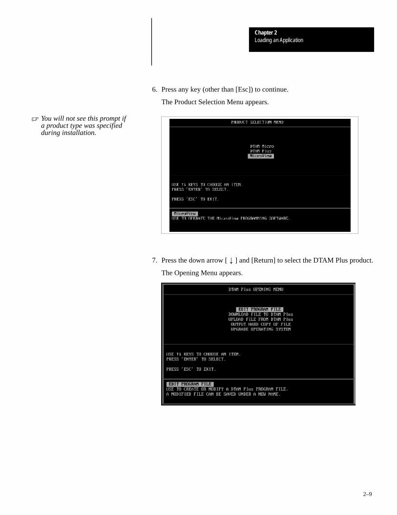
6. Press any key (other than [Esc]) to continue.
The Product Selection Menu appears.
� You will not see this prompt ifa product type was specifiedduring installation.
7. Press the down arrow [ � ] and [Return] to select the DTAM Plus product.
The Opening Menu appears.

Loading an ApplicationChapter 2
2–10
8. Highlight Download File to DTAM Plus and press [Return].
The Communication Port Selection screen appears.
� You will not see this screen if acommunication port wasspecified during DPSinstallation.
9. Highlight the serial port on your computer that is connected to theDTAM Plus (COMM 1 or COMM 2) and press [Return].
10. When communication is established, this screen appears:
11. Enter or select the file you want to download. If the application file type(DH-485, PLC5 DF1, or Remote I/O) is different from the existingDTAM Plus operating system, you are prompted to download the newoperating system.
☞ If a communication link does not occur in 10 seconds, you get anerror message. Check DTAM Plus DIP switch settings and cable connections.
☞ If a RAM memory error occurs, make sure enough computer base RAM is available. If other programs such as windows arerunning, reboot your computer to exit to DOS.
Downloading an Application
Loading an ApplicationChapter 2
2–11
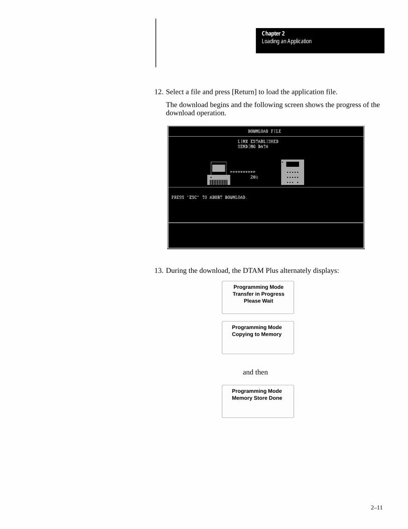
12. Select a file and press [Return] to load the application file.
The download begins and the following screen shows the progress of thedownload operation.
13. During the download, the DTAM Plus alternately displays:
Programming ModeTransfer in Progress
Please Wait
Programming ModeCopying to Memory
and then
Programming ModeMemory Store Done

Loading an ApplicationChapter 2
2–12
14. When the download is complete, you return to the Opening Menu.
and the DTAM Plus displays:
Programming ModeWaiting Up/Download
15. Press [Esc] to exit the software.
16. Press [Y] to return to DOS.
The application is now loaded in the DTAM Plus. You can test theapplication using the simulate function described in Chapter 4 or you canrun the application as described in Chapter 5.
Important: To run the application, set DIP switch SW-1 OFF. TheDTAM Plus will reset and start the application.

Loading an ApplicationChapter 2
2–13
This section shows how to upload an application from the DTAM Plus to acomputer running DPS software (Catalog No. 2707-NP). Refer to the DPSUser manual (Publication No. 2707-801) for additional instructions.
To upload an application:
1. Apply power to the DTAM Plus.
The following message appears.
Programming ModeWaiting Up/Download
If you do not see this message, check the DIP switch settings. DIP Switch SW-1 must be ON.
2. On your computer, move to the /DPS subdirectory.
C:\DPS>
3. Type dps and press [Return] to start the program.
C:\DPS>dps [Return]
4. Specify whether you are using a color monitor. Enter Y or N.
5. The startup screen displays.
Voice: 440–646–6800FAX: 440–646–6850 or 6890E–mail: [email protected]
Technical Support
� You will not see this prompt ifa monitor was specified duringDPS installation.
Uploading an Application

Loading an ApplicationChapter 2
2–14
6. Press any key (other than [Esc]) to continue.
The Product Selection Menu appears.
� You will not see this prompt ifa product type was specifiedduring installation.
7. Press the down arrow [ � ] and [Return] to select the DTAM Plus product.
The Opening Menu appears.

Loading an ApplicationChapter 2
2–15
8. Highlight Upload File from DTAM Plus and press [Return].
The Communication Port Selection screen appears.
� You will not see this screen if acommunication port wasspecified during DPSinstallation.
9. Highlight the serial port on your computer that is connected to theDTAM Plus (COMM 1 or COMM 2) and press [Return].
10. The upload begins and the following screen shows the progress of theupload operation.
11. You are prompted for the application file name. Enter the file name andpress [Return].

Loading an ApplicationChapter 2
2–16
12. When the upload is complete, you return to the Opening Menu.
13. Press [Esc] to exit the software.
14. Press [Y] to return to DOS.
The application is now loaded into the DPS software. You can edit theapplication as described in the DPS Programming Manual (PublicationNo. 2707-801).

A–B 3Chapter
3–1
Using the Function Menu
This chapter describes how to perform operations from the Function menuand contains the following sections:
Section Page
Function Key Menu 3–2
Resetting the DTAM Plus 3–3
Setting Communication Port Parameters 3–4
Displaying Remote I/O Port Parameters 3–5
Setting Printer Port Parameters 3–7
Enabling Screen Prints 3–9
Setting the Clock Calendar 3–10
Adjusting the Display Contrast 3–11
Adjusting the Display Brightness 3–12
Enabling Simulate Mode 3–13
Enabling Terminal Mode 3–14
Entering a New Master Security Code 3–16
Using Scaling 3–18
Accessing the Point /Access Display Function 3–19
Accessing Test Functions 3–20
Objectives

Chapter 3Using the Function Menu
3–2
Many DTAM Plus functions are accessed from the Function menu. Toaccess the Function menu, press the [F] key on the keypad. All otherfunctions are halted when the menu is displayed.
Note: To enable the F (Function) key, DIP switch SW-4 must be set ON.
The Function menu provides access to these functions:
1 C-Port 5 Special2 P-Port 6 Term3 Clk/Cal 7 Test4 Reset 8 Other
Select a menu item by pressing the corresponding numeric key [1] � [8].The menu structure is shown below:
Resets the DTAM Plus
Configures the Comm Port Special Controller Operations
1 C-Port 5 Special2 P-Port 6 Term3 Clk/Cal 7 Test4 Reset 8 Other
Select Item:1 Baud Rate 4 Exit2 Data Bits3 Parity
1 Baud Rate 5 L/Feed2 Data Bits 6 Penable3 Parity 7 Exit4 Hndshk
Configures the Printer Port
Sets the Clock /Calendar
1 Half Duplex2 Line Feed Enable3 Cursor Enable4 Exit
Configures Terminal Mode
Screen display dependsupon operating system.
Refer to Appendix C.
1 Simulate 5 Master C2 BL / INT 6 Scale E3 Contrast 7 Exit4 Prn Scrn
DTAM Plus DiagnosticNEXT to Select TestENTER to Initiate [Test Function]
Performs Self Tests
Accesses Additional Functions
Function Key Menu

Chapter 3Using the Function Menu
3–3
Use the Reset function to reset the DTAM Plus after DIP switch changes or aconfiguration change using the Function Key Menu.
You can also use the Reset function to activate Terminal Mode if DIP switchSW-5 is set ON.
To reset the DTAM Plus:
1. From the Function Menu, select Reset [4].
1 C-Port 5 Special2 P-Port 6 Term3 Clk/Cal 7 Test4 Reset 8 Other
This screen appears:
Press ”Y” To ResetPress ”N” To Abort
2. Press [Y] on the keypad to initiate the reset.
The DTAM Plus resets. This has the same effect as turning the power offand on. The DTAM Plus performs the self diagnostic tests and powerupdisplays as described in the previous section.
Resetting the DTAM Plus

Chapter 3Using the Function Menu
3–4
The C-Port option on the Function Menu lets you manually adjust thecommunication port parameters. Normally these parameters are set from theDPS programming software when an application is downloaded.
Select C-Port [1] from the Function Menu.
1 C-Port 5 Special2 P-Port 6 Term3 Clk/Cal 7 Test4 Reset 8 Other
This menu displays:
Select Item:1 Baud Rate 4 Exit2 Data Bits3 Parity
Exits to Function Menu
Select an item by pressing the corresponding numeric key [1] � [4].
Baud Rate
Selecting Baud Rate [1] displays the current baud rate.
Select Baud Rate:Baud Rate 2400”NEXT” To Change”ENTER” To Select
Press [NEXT] to toggle through the options: 300, 1200, 2400, 4800, 9600,19200, 38400. Press [ ] to select a new rate. DH-485 communicationswith an SLC or network cannot be set to 300 Baud.
Data Bits
Selecting Data Bits [2] displays the current setting.
Select Bit Counts:Bits 8”NEXT” To Change”ENTER” To Select
Press [NEXT] to change between 7 or 8 bits. Press [ ] to select a setting.
Parity
Selecting Parity [3] displays the current setting.
Select Parity:Parity None”NEXT” To Change”ENTER” To Select
Press [NEXT] to change between Even, Odd, or No parity. Press [ ] toselect a new parity.
Setting CommunicationPort Parameters

Chapter 3Using the Function Menu
3–5
The R–Port option allows you to display (not modify) Remote I/Oparameters for the DTAM Plus. These parameters are set from theprogramming software when an application is downloaded.
The R–Port option is only available for versions with a Remote I/O port.
To display Remote I/O communication parameters:
1. Select Special [5] from the Function Menu.
1 C-Port 5 Special2 P-Port 6 Term3 Clk/Cal 7 Test4 Reset 8 Other
This menu displays:
1. P - AD2. R - PORT
Note: P–AD functions are described in Appendix C
2. Select R–Port [2] from the menu.
This menu displays:
1 BaudRate 4 RackNum2 RackSize 5 ModuGrp3 LastRack 6 Reset
Select an item by pressing the corresponding numeric key [1] � [6].
The current setting for the selected parameter is displayed. Press [ ] toreturn to the previous menu.
Baud Rate
Selecting BaudRate [1] displays the current baud rate.
Baud Rate 230.4K
”ENTER” To Continue
Rack Size
Selecting RackSize [2] displays the current rack size.
Rack Size FULL
”ENTER” To Continue
Displaying Remote I/OPort Parameters

Chapter 3Using the Function Menu
3–6
Last Rack
Selecting LastRack [3] shows whether the DTAM Plus is configured as thelast rack.
Is Last Rack YES
”ENTER” To Continue
Rack Number
Selecting RackNum [4] displays the current rack number of the DTAM Plus.
Rack Number 02
”ENTER” To Continue
Module Group
Selecting ModuGrp [5] displays the starting module group of the DTAM Plus.
Module Group 0
”ENTER” To Continue
Reset
Selecting Reset [6] restarts the DTAM Plus (same as cycling power).

Chapter 3Using the Function Menu
3–7
The P-Port option on the Function Menu lets you manually set the RS-232printer port parameters. Normally these parameters are set automaticallyfrom the DPS programming software when an application is downloaded.
This menu options is only valid for versions that have a printer port.
Select P-Port [2] from the Function Menu.
1 C-Port 5 Special2 P-Port 6 Term3 Clk/Cal 7 Test4 Reset 8 Other
This menu displays:
1 Baud Rate 5 L/Feed2 Data Bits 6 Penable3 Parity 7 Exit4 Hndshk
Baud Rate
Selecting Baud Rate [1] displays the current baud rate.
Select Baud Rate:Baud Rate 9600”NEXT” To Change”ENTER” To Select
Press [NEXT] to toggle through the options: 300, 1200, 2400, 4800, 9600,19200, 38400. Press [ ] to select a new rate.
Data Bits
Selecting Data Bits [2] displays the current setting.
Select Bit Counts:Bits 8”NEXT” To Change”ENTER” To Select
Press [NEXT] to change between 7 or 8 bits. Press [ ] to select a setting.
Setting PrinterPort Parameters

Chapter 3Using the Function Menu
3–8
Parity
Selecting Parity [3] displays the current setting.
Select Parity:Parity None”NEXT” To Change”ENTER” To Select
Press [NEXT] to change between Even, Odd, or No parity. Press [ ] toselect a new parity.
Handshake
Selecting Hndshk [4] enables/disables handshaking. Handshaking is arequest to send a communications signal (RTS) and notification that atransmission may be sent (CTS).
HNDSHK Enable OFF (0)”1” or ”Y” = ON”0” or ”N” = OFFENTER = NC
Press [1] or [Y] to enable handshaking. Press [0] or [N] to disablehandshaking. Press [ ] to return to P-Port menu without any change.
Line Feed
Selecting L/Feed [5] enables/disables Line Feed. When enabled, The DTAMPlus sends a line feed (LF), in addition to a carriage return after a form hasbeen printed. When disabled, only a carriage return is sent.
L/Feed Enable OFF (0)”1” or ”Y” = ON”0” or ”N” = OFFENTER = NC
Press [1] or [Y] to enable a line feed. Press [0] or [N] to disable a line feed.Press [Enter] to return to P-Port menu without any change.
Port Enable
Selecting PEnable [6] enables/disables the printer port. You must enable theprinter port, to upload or download applications through the port.
PEnable ON (1)”1” or ”Y” = ON”0” or ”N” = OFFENTER = NC
Press [1] or [Y] to enable the printer port. Press [0] or [N] to disable theprinter port. Press [ ] to return to P-Port menu without any change.

Chapter 3Using the Function Menu
3–9
The Prn Scrn option allows you to send the current display screen to theprinter port when the [EXP] key is pressed on the keypad.
When the Prn Scrn option is disabled, you can only use the [EXP] key toenter floating point data.
This menu options is only valid for versions that have a printer port.
To enable printing of screens:
1. Select Other [5] from the Function menu.
1 C-Port 5 Special2 P-Port 6 Term3 Clk/Cal 7 Test4 Reset 8 Other
This menu displays:
1 Simulate 5 Mastr C2 BL / Int 6 Scale E3 Contrast 7 Exit4 Prn Scrn
2. Press [4] to select Prn Scrn.
The following screen appears.
PSCREEN Enab ON (1)”1” or ”Y” = ON”0” or ”N” = OFFENTER = NC
3. Press [1] to enable the screen prints or [0] to disable.
4. Press [7] to exit and return to the Function Menu.
Enabling Screen Prints

Chapter 3Using the Function Menu
3–10
The Clk/Cal option on the Function Menu lets you set and display theinternal real time clock of the DTAM Plus (only on versions with clockoption).
The real time clock provides time and date information for DTAM Plusoperations. You can also insert the time and date in operator screens andprint forms. Refer to your controller documentation for more details on timesynchronization.
The real time clock is accurate to +/– 1 minute per month @25° C.
To set the real time clock:
1. Select Clk/Cal [3] from the Function menu.
1 C-Port 5 Special2 P-Port 6 Term3 Clk/Cal 7 Test4 Reset 8 Other
This screen displays:
Enter Date MM.DD.YY
2. Enter a new date in the form MM.DD.YY with decimal points betweenthe MM, DD and YY. Press [ ] to store the values in the DTAM Plus.
The screen prompts you to enter a time.
Enter Date MM.DD.YY08.05.98
Enter Time HH.MM.SS
HH = Hour (0-23 or –12)MM = Minutes (0-59)SS = Seconds (0-59)
3. Enter a new time in the form HH.MM.SS with decimal points betweenthe HH, MM and SS and then press [ ].
The screen prompts you to select a 24 hour or 12 hour format.
Select Time Format”Y” = 24 Hour Format”N” = 12 Hour Format
4. Press [Y] to select 24 hour format or [N] to select 12 hour (AM/PM)format. If you press [N], you are prompted to select AM or PM.
The screen displays both the current time and date.
TIME 10:14:28DATEWed Aug 5 98
Press ”ENTER”
5. Press [ ] to return to the Function menu.
Setting the Clock/Calendar

Chapter 3Using the Function Menu
3–11
The Contrast option on the Other menu enables or disables the contrastadjustment the of the LCD display from the contrast key. Any adjustments tothe contrast from the keypad are maintained after power is cycled to theDTAM Plus. If disabled, the contrast and backlight intensity remain at theircurrent setting and cannot be changed from the keypad.
The Contrast option is only available on DTAM Plus versions with a LiquidCrystal Display (LCD).
To enable contrast adjustments from the keypad:
1. Select Other [8] from the Function menu.
1 C-Port 5 Special2 P-Port 6 Term3 Clk/Cal 7 Test4 Reset 8 Other
This menu displays:
1 Simulate 5 Mastr C2 BL / Int 6 Scale E3 Contrast 7 Exit4 Prn Scrn
2. Press [3] to select Contrast.
The following screen appears.
Current SettingContrast Enab ON(1)”1” or ”Y” = ON”0” or ”N” = OFFENTER = NC
3. Press [1] to control the contrast from the keypad or [0] to disable.
The Other menu displays.
4. Press [7] to return to the Function Menu.
Adjusting the Display Contrast(LCD versions only)

Chapter 3Using the Function Menu
3–12
The BL / INT option on the Other menu enables or disables the backlighting (LCD versions) or character intensity (VFD versions)adjustment from the keypad. Any adjustments to the brightness from thekeypad are maintained after power is cycled to the DTAM Plus. If disabled, the brightness remains at its current setting and cannot be changed from the keypad.
To enable brightness adjustments from the keypad:
1. Select Other [8] from the Function menu.
1 C-Port 5 Special2 P-Port 6 Term3 Clk/Cal 7 Test4 Reset 8 Other
This menu displays:
1 Simulate 5 Mastr C2 BL / Int 6 Scale E3 Contrast 7 Exit4 Prn Scrn
2. Press [2] to select BL / INT.
The following screen appears.
BL / INT Enab ON (1)”1” or ”Y” = ON”0” or ”N” = OFFENTER = NC
Current Setting
3. Press [1] to control brightness from the keypad or [0] to disable.
4. Press [7] to exit and return to the Function Menu.
Adjusting the Display Brightness
Chapter 3Using the Function Menu
3–13
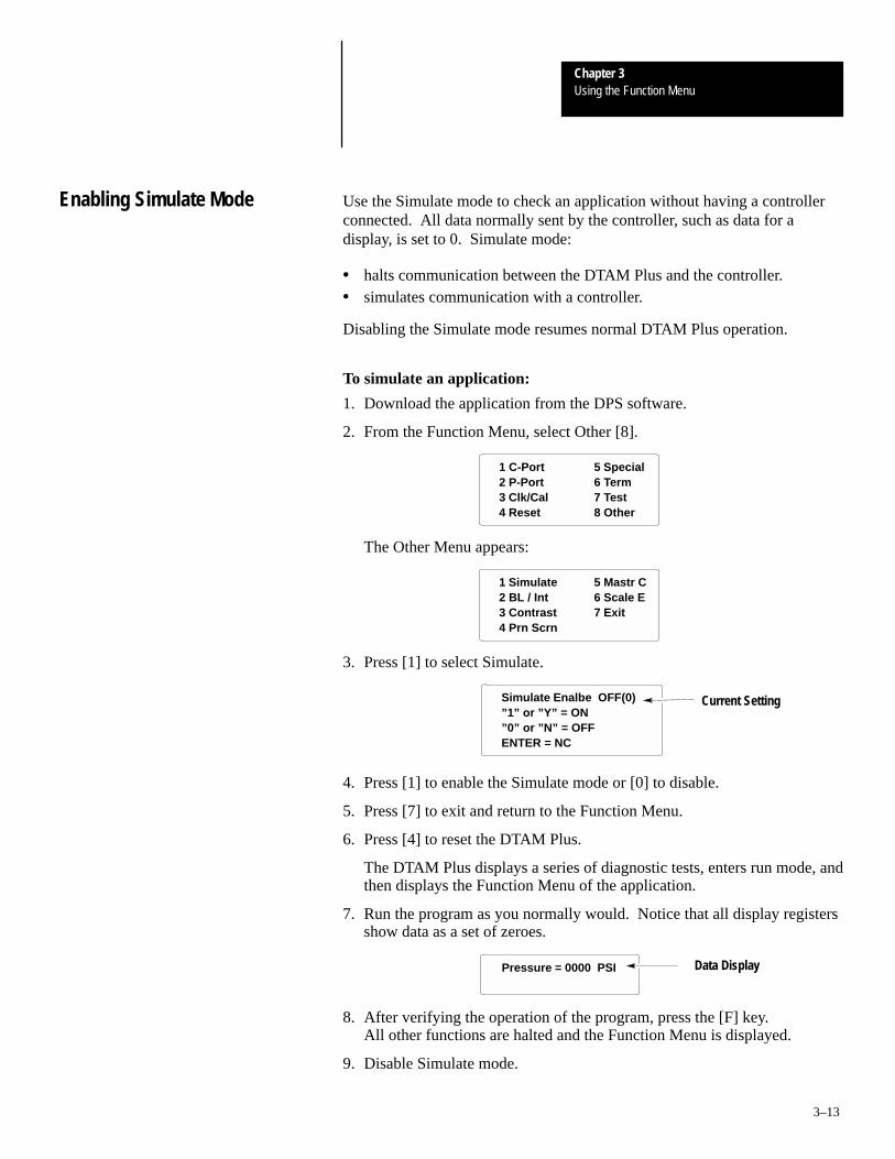
Use the Simulate mode to check an application without having a controllerconnected. All data normally sent by the controller, such as data for adisplay, is set to 0. Simulate mode:
• halts communication between the DTAM Plus and the controller.• simulates communication with a controller.
Disabling the Simulate mode resumes normal DTAM Plus operation.
To simulate an application:
1. Download the application from the DPS software.
2. From the Function Menu, select Other [8].
1 C-Port 5 Special2 P-Port 6 Term3 Clk/Cal 7 Test4 Reset 8 Other
The Other Menu appears:
1 Simulate 5 Mastr C2 BL / Int 6 Scale E3 Contrast 7 Exit4 Prn Scrn
3. Press [1] to select Simulate.
Simulate Enalbe OFF(0)”1” or ”Y” = ON”0” or ”N” = OFFENTER = NC
Current Setting
4. Press [1] to enable the Simulate mode or [0] to disable.
5. Press [7] to exit and return to the Function Menu.
6. Press [4] to reset the DTAM Plus.
The DTAM Plus displays a series of diagnostic tests, enters run mode, andthen displays the Function Menu of the application.
7. Run the program as you normally would. Notice that all display registersshow data as a set of zeroes.
Pressure = 0000 PSI Data Display
8. After verifying the operation of the program, press the [F] key. All other functions are halted and the Function Menu is displayed.
9. Disable Simulate mode.
Enabling Simulate Mode

Chapter 3Using the Function Menu
3–14
The Term option on the Function Menu lets you set communication anddisplay parameters for using the DTAM Plus in terminal mode.
Terminal Mode disables execution of the application program and enablesthe DTAM Plus to function as a terminal device.
In Terminal mode, the DTAM Plus displays any ASCII data received throughthe communications port. The ASCII codes associated with the keys on theDTAM Plus keypad are transmitted through the communications port when akey is pressed.
To activate terminal mode, you must set DIP switch SW1-5 to ON and resetthe device. The display is cleared and ready to display received data.
To set parameters for Terminal Mode:
Select Term [6] from the Function Menu.
1 C-Port 5 Special2 P-Port 6 Term3 Clk/Cal 7 Test4 Reset 8 Other
This menu displays:
1 Half Duplex2 Line Feed Enable3 Cursor Enable4 Exit Exits to Function Menu
Half Duplex
Selecting Half Duplex [1] enables/disables half duplex communications toand from the device. Enabling half duplex echoes to the display all theDTAM Plus keys pressed.
Half Duplex ON (1)”1” or ”Y” = ON”0” or ”N” = OFFENTER = NC
Press [1] or [Y] to enable half duplex. Press [0] or [N] to disable halfduplex. Press [ ] to return to P-Port menu without any change.
Enabling Terminal Mode

Chapter 3Using the Function Menu
3–15
Line Feed Enable
Selecting L/Feed [2] enables/disables Line Feed. When enabled, The DTAMPlus sends a line feed (LF) and carriage return (CR) each time a carriagereturn is received. When disabled, only a carriage return is sent.
L/Feed Enable OFF (0)”1” or ”Y” = ON”0” or ”N” = OFFENTER = NC
Press [1] or [Y] to enable a line feed. Press [0] or [N] to disable a line feed.Press [ ] to return to P-Port menu without any change.
Cursor Enable
Selecting Cursor Enable [3] enables/disables a block cursor display. Whenenabled, The DTAM Plus uses a block cursor display.
Cursor Enable ON (1)”1” or ”Y” = ON”0” or ”N” = OFFENTER = NC
Press [1] or [Y] to enable a block cursor display. Press [0] or [N] to disable athe block cursor. Press [ ] to return to P-Port menu without any change.

Chapter 3Using the Function Menu
3–16
The Special [5] menu item on the function menu may be password protectedto restrict access to the P-A/D feature. When an application has a securityscreen, the operator will be prompted for a security code. The mastersecurity code provides access to the Special menu and all other securitycodes allowing them to be modified. Two master security codes performspecial functions:
00000000 allows the operator to modify the existing master code without entering the current code.
99999999 does not allow operator to modify security codes. The mastersecurity code must be changed using the DPS software.
Note: DIP Switch SW-3 must be ON to access the master code function.
To enter a new Master Security code:
1. From the Function Menu, select Other [8].
1 C-Port 5 Special2 P-Port 6 Term3 Clk/Cal 7 Test4 Reset 8 Other
The Other Menu appears:
1 Simulate 5 Mastr C2 BL / Int 6 Scale E3 Contrast 7 Exit4 Prn Scrn
2. Press [5] to select the Master security code function.
The master code entry screen displays:
Enter Current MasterCode:_
3. Enter the current code and press [ ].
You are prompted to enter a new code.
Enter New MasterCode:_
4. Enter a new code.
Entering a New MasterSecurity Code

Chapter 3Using the Function Menu
3–17
Note: Security codes can contain the wildcard character “?”. Anyentered value will be seen as a match to the wildcard. The master securitycode must be different from security codes using wildcard entries.Otherwise the master security code may be seen as a security code. Forexample:
Security Code =12??????Master Code = 12368794
When the master security code above is entered, the DTAM Plusinterprets it as a security code.
5. Press [ ] to return to the Other menu.
6. Press [7] to return to the Function menu.
Master Security code operation:
Assuming that a security screen has been defined for the application.
1. From the Function Menu, select Special [5].
1 C-Port 5 Special2 P-Port 6 Term3 Clk/Cal 7 Test4 Reset 8 Other
You are prompted :
*RESTRICTED ACCESS*ENTER CODE:
2. If you enter a valid security code, the Special menu is displayed. If youenter the master security code, you are shown the current special securitycodes:
1 9 9 4 ? ? ? ?3 9 4 7 4 0 0 91 2 3 4 0 0 0 0Security Codes
You can modify any of the security codes.
3. Press the Enter key.
Access to the Special menu is provided:
Valid Security CodeAccess Permittted
The Special menu is then displayed.

Chapter 3Using the Function Menu
3–18
Use scaling to convert data from a controller to engineering units such asgallons or psi. When scaling is disabled, the values are not converted. Referto the DTAM Programming Software Manual for a description of how valuesare scaled. The scaling factor is determined by the application designer, itcannot be changed by the operator.
PLC-5
Flow RateTransducer
Flow RateTransducerValue = 510
Value FromController = 510
DTAM Plus displaysscaled value of
16 Gallons Per Minute
Flow = 16 Gallons Per Minute
To enable or disable scaling:
1. From the Function Menu, select Other.
1 C-Port 5 Special2 P-Port 6 Term3 Clk/Cal 7 Test4 Reset 8 Other
The Other Menu appears:
1 Simulate 5 Mastr C2 BL / Int 6 Scale E3 Contrast 7 Exit4 Prn Scrn
2. Press [6] to select Scale Enable.
The scale enable screen appears:
Scale Enalbe ON(0)”1” or ”Y” = ON”0” or ”N” = OFFENTER = NC
Current Setting
3. Press [1] on the keypad to enable scaling or [0] to disable scaling.
You return to the Other Menu.
4. Press [7] to exit to the Function Menu.
Using Scaling

Chapter 3Using the Function Menu
3–19
The Point - Access / Display function allows you to display and modifycontroller data files. The P-A/D function does not allow you to writecontroller Input and Output files.
Appendix C provides a listing of the applicable file types for SLC and PLC-5 controllers, along with step-by-step instructions on how to use theP-A/D function.
To access the Point - Access/Display Function:
1. From the Function Menu, select Special [5].
1 C-Port 5 Special2 P-Port 6 Term3 Clk/Cal 7 Test4 Reset 8 Other
This menu displays:
SLC 50X Network AddrPress
”Y’ to Edit Address”N” to Bypass
1. P – A/D2. R – PORT
Remote I/OOperating System
PLC5 DF1Operating System
DH485Operating System
DTAMPlus:00 Max:02SLC Expected At 01Input NewSLC Node01* Press ENTER
1. P – A/D2. SLC 50X Mode3. Memory Transfer4. Clear SLC Fault
1. P – A/D2. PLC Mode3. Memory Transfer4. Clear PLC Fault
* Only applies to the P-A/D function.
2. Select the P-A/D [1] option.
3. See Appendix C for details on how to use the P-A/D function.
Note: When an application is created (using DPS programming software), aspecial security screen can be configured that restricts access to the SpecialMenu.
Accessing the Point/AccessDisplay Function

Chapter 3Using the Function Menu
3–20
Use the Test menu to perform variety of tests that check the status of theDTAM Plus functions and hardware. You can access all of the Test optionsfrom the Function menu.
This section shows how to access the test functions. For details on how toperform each test, see Chapter 7 Troubleshooting and Maintenance.
To access the Test functions:
From the Function Menu, select Test [7].
1 C-Port 5 Special2 P-Port 6 Term3 Clk/Cal 7 Test4 Reset 8 Other
The test screen appears:
DTAM Plus DiagnosticNEXT to Select TestENTER To Initiate
Reset DUT Current Test Selection
The last line displays the current text selection. Press [NEXT] to togglethrough all the options. Press [ ] to initiate the selected test.
You can run the following tests from the Test menu.
• Reset DUT (DTAM Under Test)• DIP switch positions• Display• Keyboard• Communications port• Printer Port• Display Control• Random Access Memory (RAM)• System Memory• Program File• Clock/Calendar• Transmit Enable and Alarm
Accessing Test Functions

A–B 4Chapter
4–1
Running Applications
This chapter describes screen types and operating procedures that arecommon to most applications. It contains the following sections:
Section Page
DIP Switch Setting 4–1
Application Documentation 4–1
Screen Types 4–2
Screen Navigation 4–2
Menu and Sub-Menu Screens 4–3
Security Screens 4–3
Data Display Screens 4–4
Bar Graph Screens 4–4
Data Entry Screens 4–4
ASCII Input 4–5
Recipe Screens 4–6
Alarm Screens 4–6
Before an application can be run, verify that the DIP switch SW-1 is OFF.This enables the run mode. Refer to the DIP switch description on page 1–5.
It is the responsibility of the application designer to document the operationof an application program. This chapter only provides basic guidelines.Before running an application, you should understand what processes arebeing controlled and monitored.
Chapter Objectives
DIP Switch Setting
ApplicationDocumentation

Chapter 4Running Applications
4–2
Application screens can have a variety of appearances. The DTAM Plus candisplay seven types of screens.
• Menu and Sub-Menu Screens• Security Screens• Data Display Screens• Data Entry Screens• Recipe Screens• Bargraph Screens• Alarm Screens
The DTAM Plus provides several options for changing the screen displays:
• Screen links• Advisor option
Screen Links
Use the [NEXT] and [PREV] keys to step backward and forward through thissequence.
Main Menu and Sub-Menu screens list screens that can be accessed bypressing the assigned numeric key [1] through [8]. A typical Main Menuscreen provides links to individual screens or sub-menus:
1 Pump2 Tank Stat3 Mixer Stat4 Recipe
In the example above, pressing [2] at the Main Menu displays the status of aholding tank. Pressing [4] displays a Sub-Menu of the recipe screen options.
Advisor Option
Applications can allow screen changes that are controlled by an SLC or PLClogic controller. When the logic controller writes a valid screen number to aspecified Advisor register, the corresponding screen is displayed. Thecontroller can initiate a screen change based upon a variety of inputs to thecontroller. For example, a pressure limit switch can be used to initiate thedisplay of a pressure control screen. It is the responsibility of the applicationdesigner to document when and what screen changes may occur.
Screen Types
Screen Navigation

Chapter 4Running Applications
4–3
Menus and Sub-Menus provide a convenient method of accessing a largenumber of display screens.
Main Menu
Every application has a Main Menu screen. The Main Menu is the firstapplication screen displayed after an initial power-up or reset.
1 Pump2 Tank Stat3 Mixer Stat4 Recipe
The Main Menu provides access to the next level of screens and Sub-Menus.To access the Main Menu, press the [MAIN MENU] key. Pressing this keyat any time displays the Main Menu. The only time the Main Menu will notbe displayed is when an alarm screen has been triggered but notacknowledged. You must acknowledge alarm screens, by pressing [Y],before another screen can be displayed.
Sub-Menus
Sub-Menu screens function like the Main Menu. The only difference is thatyou must navigate through the other screens to access the Sub-Menus.
Security screens limit access to parts of an application. Although the text ona security screen may be changed by the application designer, manyapplications will use the default text:
*RESTRICTED ACCESS*ENTER CODE:
A security code is a series of 1 to 8 digits. Each security screen can have upto 3 code entries. Entering any one of the codes provides access.
To enter a security code, use the numeric keypad. An asterisk (*) isdisplayed for each number entered. Press [ ] after the entire code isentered.
If a valid security code has been entered, the next linked screen is displayed.If an invalid security code is entered, an error message appears. Once theerror condition is acknowledged by pressing [Y], you can re-enter the codeor return to the Main Menu.
Menu and Sub-Menu Screens
Security Screens

Chapter 4Running Applications
4–4
Data display screens show either the actual or scaled value of a logiccontroller data address.
Pump 1 Pressure = 150 PSICounter = 5
Data Display Field
Data Display Field
Data displays are updated at different intervals depending upon theapplication and the size of the network.
Bar graph displays provide a graphical representation of an actual or scaledvalue at a logic controller data address.
1700
Bar graph displays may also contain a data display field showing the actualnumeric value.
Data entry screens contain an entry field. The length and format of the dataentry field is selected by the application designer. In addition, the applicationdesigner can place a data display field on the same screen:
Temp = 120 Deg FEnter New Temp:
Data Entry Field
Data Display Field
The data entry field must always appear last on the screen. The applicationdesigner cannot place text after a data entry field.
To enter data, use the numeric keypad. To modify an entry, press the clearentry key [CE] and re-enter the value. Press the [+/–] key to toggle betweenpositive and negative values. Press [ ] after the entire value is entered.
Data entry screens can have a default value appear in the data entry field. A flashing cursor identifies the first digit of the default value. Pressing[ ] writes the default to the controller or you can enter a different value bypressing the [CE] key.
If a data display is included on a data entry screen, the data display value isonly updated when the screen is entered. Data does not update continuously.
Data Display Screens
Bar Graph Screens
Data Entry Screens

Chapter 4Running Applications
4–5
The DTAM Plus allows ASCII data to be directly entered from a device suchas a bar code scanner. An ASCII entry screen looks like a standard dataentry display. When the ASCII input screen is displayed, data can then beentered through the ASCII device connected to the printer port using the2707-NC6 cable.
Here are some items you should note when using a bar code scanner as aninput device for data entry fields.
• Odd character counts from the scanner are rounded up to create even bytecounts. This facilitates word writes to the controller. If rounded up, thelast character written will be a Null.
• When displaying an ASCII data entry screen, the following DTAM keysare active:
MAINMENU
PREVMENU
PREV NEXT
and the following keys are inactive:
EXP
F
and the key is not available for printing screens
• If keypad entry is enabled, you can enter the ASCII character’s decimalequivalent value into the data entry field. The ASCII input is alsoenabled at the same time. This allows input from both sources. Forexample, an operator can manually enter 3 characters and then scan a barcode containing 8 characters. The DTAM would then write all 11characters to the controller. Data is written to the controller on receipt ofan ASCII carriage return or when the [RETURN] key is pressed.
ASCII Input

Chapter 4Running Applications
4–6
Recipe screens allow the DTAM Plus to write to multiple controlleraddresses in one operation. Recipe screens can also be linked so that morethan one recipe is downloaded.
T4:14.2 (Timer Value)N7:30 = 0 (Integer Value)N7:31 = 100 (Integer Value)T4:15.1 (Timer Value)N7:200 = 500 (Integer Value)B3:10 = 10 (Binary Value)
Operator InitiatesRecipe Download
DTAM Plus DownloadsData to Multiple Controller Addresses
Controller Modifies ProcessUsing New Recipe Data
Download Recipe 323?Press ENTER to send
Depending on how the application was designed, recipe screens will eitherautomatically download data or display a prompt allowing the download tobe initiated when [Y] is pressed.
PRESS ’Y’ TO SEND
Once the download is initiated, the DTAM Plus writes the recipe data to thevarious controller addresses. You cannot modify the recipe data that is sent,recipe data is specified by the application designer.
Alarm screens indicate conditions that are not expected during normaloperation. Alarm screens are triggered when the controller writes the alarmscreen number to the Advisor register or when triggered by the backgroundmonitor. Refer to page 4–2 for additional information on the Advisoroption.
You must respond to an alarm screen before any other screens can bedisplayed. The [F] key (accessing function menu) will not operate while analarm screen is displayed. Press [Y] to acknowledge the alarm.
PRESS ’Y’ TO CLEAR
Recipe Screens
Alarm Screens

A–B 5Chapter
5–1
Installation
This chapter contains the following sections:
Section Page
Safety Guidelines 5–1
Operating Environment 5–2
Enclosures 5–3
Equipment Required 5–3
Clearances 5–3
Mounting Dimensions 5–4
Cutout Template 5–5
Installation 5–6
Connecting Power 5–7
Install the DTAM Plus using publication NFPA 70E, Electrical SafetyRequirements for Employee Workplaces as a guide.
In addition, grounding is an important safety measure in electricalinstallations. A source for grounding recommendations is the NationalElectrical Code published by the National Fire protection Association ofBoston Massachusetts.
Be certain to follow all directions for installing and connecting power to theDTAM Plus.
When used in a hazardous environment, the ultimate enclosure must be inaccordance with Class 1, Division 2 wiring methods as described in theNational Electrical Code (ANSI/NFPA 70) and the Canadian Electrical Code.
All peripheral equipment must be suitable for the location in which it is used.
For P1 powered units, use only a Class 2 power source as described in theNational Electrical Code (ANSI/NFPA 70) and the Canadian Electrical Code.
Objectives
Safety Guidelines

Chapter 5Installation
5–2
!ATTENTION: EXPLOSION HAZARD: SUBSTITUTION OFCOMPONENTS MAY IMPAIR SUITABILITY FOR CLASS1, DIVISION 2.
RISQUE D’EXPLOSION: LA SUBSTITUTION DECOMPOSANTS PEUT RENDRE CE MATÉRIELINACCEPTABLE POUR LES EMPLACEMENTS DECLASSE 1, DIVISION 2.
!ATTENTION: USE P1 POWERED UNITS ONLY WITHCLASS 2 POWER SOURCE LIMITED TO 30 VDC OPENCIRCUIT AND 8A SHORT CIRCUIT.
ATTENTION: UTILISER AVEC UNE TENSIOND’ALIMENTATION CLASSE 2 DE 30 VCC MAXI ENCIRCUIT OUVERT AVEC UN COURANT DECOURT-CIRCUIT DE 8A MAXI.
!ATTENTION: EXPLOSION HAZARD: DO NOT CONNECT ORDISCONNECT EQUIPMENT WHILE CIRCUIT IS LIVEUNLESS AREA IS KNOWN TO BE NON-HAZARDOUS.
RISQUE D’EXPLOSION: NE PAS BRANCHER OUDEBRANCHER TANT QUE LE CIRCUIT EST SOUSTENSION, A MOINS QU’IL NE S’AGISSE D’UNEMPLACEMENT NON DANGEREUX.
Refer to the inside front cover of this manual for additional guidelines.
The DTAM Plus is rated for an operating temperature range of:
• LCD displays – 32�F to 113�F (0�C to 45�C)• VFD displays – 32�F to 140�F (0�C to 60�C)
The storage temperature range is -4°F to 185°F (-20°C to 85°C). The humidity rating is 5% to 95% relative humidity (noncondensing).
Operating Environment

Chapter 5Installation
5–3
The terminal must be mounted in a panel or enclosure to protect the internalcircuitry. The terminal meets NEMA Type 4, 12, 13 (indoor use only) or 4X(indoor 2707-V40P2N, -V40P2NR) ratings only when mounted in a panel orenclosure with the equivalent rating.
Allow enough spacing within an enclosure for adequate ventilation. Forsome applications, you may have to consider heat produced by other deviceswithin a panel. The ambient temperature around the terminal must bemaintained as specified above.
Make sure that provisions are made for accessing the back panel of theterminal for wiring, routine maintenance, and troubleshooting.
Other than the tools required to make the panel cutout, the tools required forinstallation are:
• 7mm (M4) deep well socket wrench or nut driver• small slotted screwdriver• torque wrench (in. / lbs).
The terminal is tightened against the panel with six self-locking nuts.
Make sure that you leave adequate room, as shown in Figure 5.1, formounting, air flow, cabling and access to DIP switches.
Figure 5.1Recommended Clearances
Leave 3 inches (76.2 mm)for Mounting, Air Flow, and
access to DIP Switches.
Leave 3 inches (76.2 mm) for communications port connectors.
Enclosures
Equipment Required
Clearances
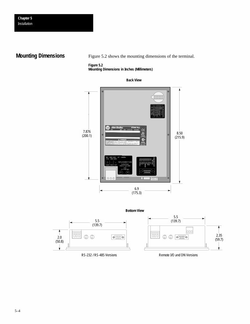
Chapter 5Installation
5–4
Figure 5.2 shows the mounting dimensions of the terminal.
Figure 5.2Mounting Dimensions in Inches (Millimeters)
7.876(200.1)
Bottom View
6.9(175.3)
8.50(215.9)
5.5(139.7)
2.35(59.7)
2.0(50.8)
5.5(139.7)
Back View
Remote I/O and DN VersionsRS-232 / RS-485 Versions
Mounting Dimensions

Chapter 5Installation
5–5
A cutout template is provided on the inside back cover of this manual tomark the cutout dimensions. Figure 5.3 provides a reference copy, don’tremove this page from the manual.
Figure 5.3Panel Cutout Dimensions in Inches (Millimeters)
Cutout Template

Chapter 5Installation
5–6
To install the DTAM Plus Operator Module:
Disconnect all electrical power from the panel before making cutout.
Make sure that area around panel cutout is clear.
Take precautions so that metal filings or other debris do notfall into the DTAM Plus ventilation slots or enter anycomponents that may already be installed in panel.
Make sure that no objects are inserted or fall into the terminalthrough the ventilation slots or DIP switch access hole.
Failure to follow these warnings may result in personal injuryor damage to the panel components.
ATTENTION:
!
1. Cut an opening in the panel as shown in Figure 5.3. Use the cutouttemplate located inside the back cover of this manual. Remove any sharpedges or burrs.
2. Make sure the sealing gasket is properly positioned on the DTAM PlusThis gasket forms a compression type seal. Do not use sealingcompounds.
3. Place the DTAM Plus in the panel cutout.
Mounting nuts must be tightened to a torque of 8 to 10 inchpounds to provide a proper seal and to prevent potentialdamage to the terminal. Allen-Bradley assumes noresponsibility for water or chemical damage to the terminal orother equipment within the panel enclosure because ofimproper installation.
ATTENTION:
!
4. Install the six self locking mounting nuts hand tight.
5. Alternately tighten the mounting nuts until the DTAM Plus is held firmlyagainst the panel. Tighten mounting nuts to a torque of 8 to 10inch-pounds. Do not over-tighten nuts.
Installation
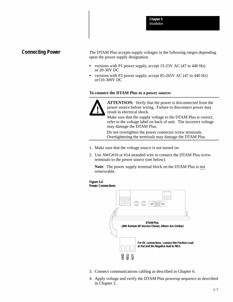
Chapter 5Installation
5–7
The DTAM Plus accepts supply voltages in the following ranges dependingupon the power supply designation.
• versions with P1 power supply, accept 15-23V AC (47 to 440 Hz) or 20-30V DC
• versions with P2 power supply, accept 85-265V AC (47 to 440 Hz)or110-300V DC
To connect the DTAM Plus to a power source:
!ATTENTION: Verify that the power is disconnected from thepower source before wiring. Failure to disconnect power mayresult in electrical shock.Make sure that the supply voltage to the DTAM Plus is correct,refer to the voltage label on back of unit. The incorrect voltagemay damage the DTAM Plus.Do not overtighten the power connector screw terminals.Overtightening the terminals may damage the DTAM Plus.
1. Make sure that the voltage source is not turned on.
2. Use AWG#16 or #14 stranded wire to connect the DTAM Plus screwterminals to the power source (see below).
Note: The power supply terminal block on the DTAM Plus is notremoveable.
Figure 5.4Power Connections
DTAM Plus (40K Remote I/O Version Shown, Others Are Similar)
For DC connections, connect the Positive Leadto Hot and the Negative lead to NEU.
3. Connect communications cabling as described in Chapter 6.
4. Apply voltage and verify the DTAM Plus powerup sequence as describedin Chapter 2.
Connecting Power

A–B 6Chapter
6–1
Communication Connections and Setup
This chapter describes how to connect the DTAM Plus to peripheral devices.It contains the following sections:
Section Page
Wiring Guidelines 6–1
Connecting RS-232 Devices 6–2
Connecting RS-485 Devices 6–3
Connecting Remote I/O Devices 6–5
Communicating with a Logic Controller 6–6
RS-232 or RS-422 Communications with a PLC-5 6–7
RS-232 Communications with an SLC 5/03, –5/04 6–8
DH-485 Communication with an SLC 500 or Network 6–9
RS-232 Communications with a MicroLogix 1000 6–10
RS-485 Communications with a MicroLogix 1000 6–11
DH-485 Communications with a MicroLogix 1000 6–12
Here are some recommendations on how to reduce electromagnetic noise onthe communications connections:
• Careful wire routing helps reduce or minimize electrical noise. Routeincoming power to the terminal by a separate path from thecommunications cables.
• Do not run communications wiring and power wiring in the same conduit.• Where communications and power wiring must cross, make their
intersection perpendicular.• Proper grounding helps to reduce the effects of noise due to
Electromagnetic Interference (EMI). To avoid problems caused by EMI,all cables must be shielded and grounded at one end. Grounding is alsoan important safety measure in electrical installations.
Chapter Objectives
Wiring Guidelines

Chapter 6Communication Connections and Setup
6–2
The RS-232 Comm port of the DTAM Plus allows point-to-pointcommunications with:
• PLC-5 Channel 0 (configured as RS-232 port)• SLC 5/03, 5/04, 5/05 Channel 0 (configured as RS-232 port)• MicroLogix 1000
The figure below shows typical RS-232 connections.
DTAM Plus to PLC5 Channel 0
RS-232
PLC-5
Cable (Catalog No. 2707-NC3)
Channel 0
DTAM Plus to SLC 5/03, 5/04,5/05
RS-232
Channel 0
SLC 5/03
Cable (Catalog No. 1747-CP3)
Gender Adapter
Comm Port
DTAM Plus
Comm Port
DTAM Plus
To connect the DTAM Plus to an RS-232 device:
1. Make sure that the DTAM Plus is not connected to a voltage source.
2. Use the proper cabling to connect the DTAM Plus Comm port to the portof the controller (PLC-5 channel 0 or SLC 5/03 RS-232 port).
• Use cable, Catalog No 2707-NC3 for PLC-5 channel 0 connection.• Use cable, Catalog No. 1747-CP3 for SLC 5/03, 5/04, 5/05 port
connection. This cable requires a 9-pin female to male gender adapter.
If you need to make your own cable, refer to the cable diagrams inAppendix B. The maximum recommended cable length is 50 feet (15.2 meters).
3. Make sure that the communication parameters of the DTAM Plus matchthe host device.
4. Apply power and verify that communications are established.
Connecting RS-232Devices

Chapter 6Communication Connections and Setup
6–3
The RS-485 Comm port allows:
• Point-to-point communications with a PLC-5 Channel 0 port
• Point-to-point or multidrop communications with an SLC controllerDH-485 port
• MicroLogix 1000 using the AIC+ Interface
The figure below shows typical RS-485 connections.
DTAM Plus to Single SLC
DTAM Plus to PLC5 Channel 0
RS-422
PLC-5
Cable (Catalog No. 2707-NC4)
SLC
Comm Port
Channel 0
RS-485
Cable (Catalog No. 2707-NC1)
Comm Port
DTAM Plus
DTAM Plus
(Point-to-Point Only)
(Point-to-Point)
RS-422
RS-485
DTAM Plus to PLC5 Channel 0
RS-232
PLC-5
Cable (Catalog No. 2707-NC5)
Comm Port
Channel 0
DTAM Plus
(Point-to-Point Only)
RS-232
RS-485
RS-485
Connecting RS-485 Devices
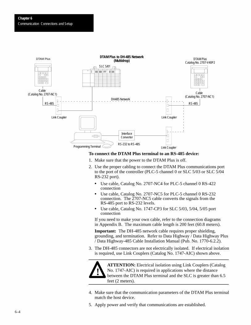
Chapter 6Communication Connections and Setup
6–4
DTAM Plus to DH-485 Network
SLC 5/01
InterfaceConverter
Programming Terminal
Link Coupler
Link Coupler
Link Coupler
RS-232 to RS-485
DTAM PlusCatalog No. 2707-V40P2
DH485 Network
Cable (Catalog No. 2707-NC1)
Cable (Catalog No. 2707-NC1)
DTAM Plus (Multidrop)
RS-485RS-485
To connect the DTAM Plus terminal to an RS-485 device:1. Make sure that the power to the DTAM Plus is off.
2. Use the proper cabling to connect the DTAM Plus communications portto the port of the controller (PLC-5 channel 0 or SLC 5/03 or SLC 5/04RS-232 port).
• Use cable, Catalog No. 2707-NC4 for PLC-5 channel 0 RS-422connection
• Use cable, Catalog No. 2707-NC5 for PLC-5 channel 0 RS-232connection. The 2707-NC5 cable converts the signals from theRS-485 port to RS-232 levels.
• Use cable, Catalog No. 1747-CP3 for SLC 5/03, 5/04, 5/05 portconnection
If you need to make your own cable, refer to the connection diagrams in Appendix B. The maximum cable length is 200 feet (60.8 meters).
Important: The DH-485 network cable requires proper shielding,grounding, and termination. Refer to Data Highway / Data Highway Plus/ Data Highway-485 Cable Installation Manual (Pub. No. 1770-6.2.2).
3. The DH-485 connectors are not electrically isolated. If electrical isolationis required, use Link Couplers (Catalog No. 1747-AIC) shown above.
!ATTENTION: Electrical isolation using Link Couplers (CatalogNo. 1747-AIC) is required in applications where the distancebetween the DTAM Plus terminal and the SLC is greater than 6.5feet (2 meters).
4. Make sure that the communication parameters of the DTAM Plus terminalmatch the host device.
5. Apply power and verify that communications are established.

Chapter 6Communication Connections and Setup
6–5
The Remote I/O port of the DTAM Plus provides access via a Remote I/Olink directly to a controller or subscanner. Use cable (Catalog No. 1770-CD)Belden 9463 for all Remote I/O connections. Refer to Publication No.1770-4.1 for detailed grounding and wiring guidelines. The user manual foryour controller or subscanner will also provide cabling instructions.
The following figures show typical Remote I/O connections.
PLC-5
RediPANEL
Remote I/O Network
PanelView
Remote I/O DL40 Plus
Computer
Cabling (Catalog No.1770-CD) Belden 9463
DTAM Plus Operator Interface
SLC 5/03, 5/04, 5/05
DTAM Plus Remote I/O Port
Cabling (Catalog No. 1770-CD) Belden 9463
RIO Scanner(Catalog No. 1747-SN)
DTAM Plus to an Remote I/O Link
DTAM Plus Operator Interface
DTAM Plus to an SLC 5/03, 5/04, 5/05 Remote I/O Scanner
Connecting Remote I/ODevices

Chapter 6Communication Connections and Setup
6–6
The DTAM Plus supports four operating systems.
• Remote I/O• PLC5-DF1• AB BASIC• AB DH-485 protocol
The type of operating system supported by the DTAM Plus depends upon itscommunication configuration.
DTAM Plus Version OperatingSystem Controller Type
RS-485 / RS-232 Versions(Catalog No. 2707-L8P1, -L8P2,
PLC5 DF1 PLC-5 Family channel 0 port (RS-422) ➀
(Catalog No. 2707-L8P1, -L8P2,-L40P1, -L40P2, -V40P1, -V40P2,-V40P2N)
AB DH485 SLC Family DH-485 portDH-485 networkSLC 5/03, 5/04 serial port
Remote I/O Versions(Catalog No. 2707-L8P1R, -L8P2R,-L40P1R, -L40P2R, -V40P1R,-V40P2R, -V40P2NR)
Remote I/O PLC / SLC Controllers with Remote I/O link orsubscanner.
➀ The DTAM Plus RS-485 port supports RS-422 communication with the PLC-5. RS-422 communication is limited by the PLC to 19.2K baud and a distance of 200 feet (61 meters).
The operating system is selected when an application is created. Applications are downloaded with the applicable operating system. If youdownload an application that has a different operating system than thecurrent operating system in the DTAM Plus, you are prompted to downloadthe new operating system. Refer to Chapter 2 for additional information.
Communications Parameters
The communication settings of the DTAM Plus must be set to match theSLC, PLC, or DH-485 network. You can set the following parameters (asdescribed in Chapter 3):
Parameter Selections
Baud Rate 300, 1200, 2400, 4800, 9600, 19200, 38400
Data Bits 7 or 8
Parity None, Odd, and Even
Remote I/O versions of the DTAM Plus support direct links to a PLC scanneror subscanner module. The DTAM Plus appears to the PLC as a standard1771 I/O rack.
Remote I/O Communications Parameters Options
Baud Rate 57.6K, 115.2K, 230.4K
Rack Size 1/4, 1/2, 3/4, Full
Communicating with a LogicController
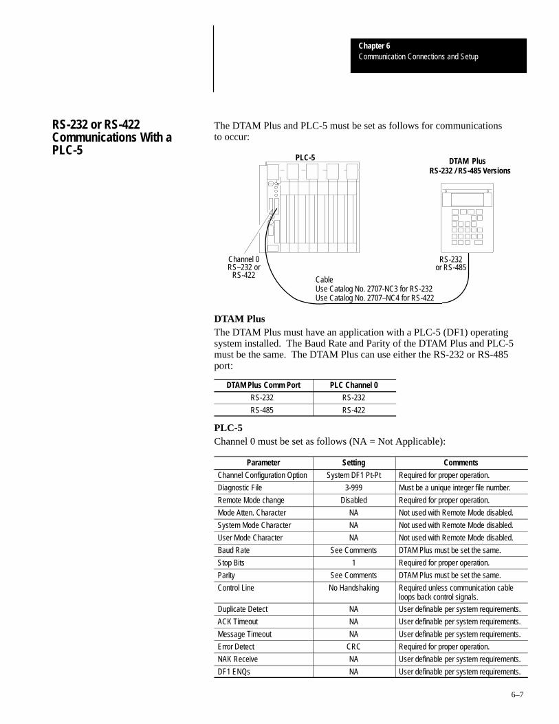
Chapter 6Communication Connections and Setup
6–7
The DTAM Plus and PLC-5 must be set as follows for communications to occur:
RS-232
DTAM PlusPLC-5
Channel 0
RS-232 / RS-485 Versions
RS–232 orRS-422
or RS-485
CableUse Catalog No. 2707-NC3 for RS-232Use Catalog No. 2707–NC4 for RS-422
DTAM PlusThe DTAM Plus must have an application with a PLC-5 (DF1) operatingsystem installed. The Baud Rate and Parity of the DTAM Plus and PLC-5must be the same. The DTAM Plus can use either the RS-232 or RS-485port:
DTAM Plus Comm Port PLC Channel 0
RS-232 RS-232
RS-485 RS-422
PLC-5Channel 0 must be set as follows (NA = Not Applicable):
Parameter Setting Comments
Channel Configuration Option System DF1 Pt-Pt Required for proper operation.
Diagnostic File 3-999 Must be a unique integer file number.
Remote Mode change Disabled Required for proper operation.
Mode Atten. Character NA Not used with Remote Mode disabled.
System Mode Character NA Not used with Remote Mode disabled.
User Mode Character NA Not used with Remote Mode disabled.
Baud Rate See Comments DTAM Plus must be set the same.
Stop Bits 1 Required for proper operation.
Parity See Comments DTAM Plus must be set the same.
Control Line No Handshaking Required unless communication cableloops back control signals.
Duplicate Detect NA User definable per system requirements.
ACK Timeout NA User definable per system requirements.
Message Timeout NA User definable per system requirements.
Error Detect CRC Required for proper operation.
NAK Receive NA User definable per system requirements.
DF1 ENQs NA User definable per system requirements.
RS-232 or RS-422Communications With aPLC-5

Chapter 6Communication Connections and Setup
6–8
The DTAM Plus and RS-232 port of the SLC 5/03, 5/04, 5/05 must be set asfollows for communications to occur:
RS-232C
DTAM Plus
Channel 0
SLC 5/03, 5/04, 5/05
Cable (Catalog No. 1747-CP3)
GenderAdapter
RS-232 / RS-485 Versions
Gender Adapter Required
Comm Port
DTAM Plus
The DTAM Plus must have an application with AB DH485 operating systeminstalled. The Baud Rate and Parity of the DTAM Plus and the SLC 5/03,5/04, 5/05 must be the same. We recommend you use 19200 baud, evenparity, and 8 data bits to match the default settings of an SLC 500controller.
SLC 5/03, 5/04, 5/05
Make sure that the channel 0 port of the SLC controller is set for DH-485MASTER using the following parameters.
Parameter Selections Recommended
Baud Rate 1200, 2400, 9600, 19.2K 19.2K
Node Address 0 to 31 1①
Maximum Node Address
0 to 31 1①
Token Hold Factor 1 to 4 1
Diagnostic File Number 0 to 255 Any
Parity None, Odd, or Even Even②
Data Bits 7 or 8 8
① To provide maximum response times, we recommend that the DTAM Plus be set as node 0 and theSLC 500 channel 0 as node 1. Maximum node address should be 1. The connections are a completely separate DH-485 network, you do not need to be concerned about duplicate node addresses from another network.
② SLC 5/03, 5/04, 5/05 (channel 0) only support EVEN parity.
RS-232 Communications withan SLC 5/03, -5/04, -5/05

Chapter 6Communication Connections and Setup
6–9
The DTAM Plus and SLC 500 DH-485 port must be set as follows forcommunications to occur. If you are using an SLC 5/03, 5/04, 5/05 RS-232port, refer to the previous section.
RS-485
SLC 500
Cable (Catalog No. 2707-NC1)
Link Coupler
DH-485 Network
Link Coupler
SLC 500
DH-485 Network
RS-485Cable (Catalog No. 2707-NC1)
DTAM PlusRS-232 / RS-485 Versions
DTAM PlusRS-232 / RS-485 Versions
Comm Port
Comm Port
DTAM Plus
The DTAM Plus must have an application with the AB DH485 operatingsystem installed. The baud rate, parity, and data bits of the DTAM Plus andDH-485 network (or SLC 500) must be set the same. We recommend youuse 19200 baud, even parity, and 8 data bits to match the default settingsof an SLC 500 controller.
If the DTAM Plus module is installed on a DH-485 network that has a largenumber of nodes connected and there is heavy network traffic, the networkmay produce NAK NOMEM commands. Three consecutive NAK NOMEMcommands will produce a 10H error on the DTAM Plus module. Pressingthe enter key or resetting the module is required to resume operation.
DH-485 Communications withan SLC 500 or Network

Chapter 6Communication Connections and Setup
6–10
SLC 5/03, 5/04, 5/05 (channel 0)
Make sure that the SLC DH-485 port is configured as follows:
Parameter Selections Recommended
Baud Rate 1200, 2400, 9600, 19.2K 19.2K
Node Address 0 to 31 Next lowest address on thenetwork. Set to 1 for point-topoint communications ① .
Maximum Node Address
0 to 31 Set to maximum node on net-work. Set to 1 for point-topoint communications ① .
Token Hold Factor 1 to 4 1
Diagnostic File Number 0 to 255 Any
Parity None, Odd, or Even Even②
Data Bits 7 or 8 8
① For maximum response times on point-to-point networks, we recommend:To transfer data quickly from the SLC 500 to the DTAM set as the SLC as node 0 and the DTAM asnode 1. Maximum node address should be 1.To transfer data quickly from the DTAM to the SLC 500 set as the DTAM as node 0 and the SLC asnode 1. Maximum node address should be 1.
② SLC 5/03, 5/04, 5/05 (channel 0) only supports EVEN parity.
The DTAM Plus must be set as follows for communication to occur. TheDTAM module uses DH485 protocol but the comm port is set for RS-232(switch 1 position 2 is open).
Cable (Catalog No. 2707-NC2)
DTAM Plus
DH485
Cable (Catalog No.
1761-CBL-HM02)
RS-232
MicroLogix 1000
AIC+
RS-232
Cable (Catalog No. 2707-NC10)
DTAM Plus
Comm Port (RS-232)
MicroLogix 1000
RS-232
Comm Port (RS-232)
RS-232 Communications witha MicroLogix 1000

Chapter 6Communication Connections and Setup
6–11
The DTAM Plus must be set as follows for communication to occur. TheDTAM module uses DH485 protocol but the comm port is set for RS-485(switch 1 position 2 is on). This is a 3-node network and is not expandable.
DTAM Plus
Comm Port (RS485)
Cable (Catalog No.
1761-CBL-HM02)
RS232
MicroLogix 1000
AIC+DH485
RS232Com 1
Personal Computer
You will need to construct a cable that connects to the AIC+ and the DTAMPlus/Micro. Refer to the following illustration.
Termination
AIC+Port 3Communications Port
DTAM Plus
9-Pin Male D Connector
A
Common
1
2
3
4
5
1
2
3
4
8
9
6
B
Shield
Chassis Ground
6-Pin Connector
RS-485 Communications witha MicroLogix 1000

Chapter 6Communication Connections and Setup
6–12
The DTAM Plus must be set as follows for communication to occur. TheDTAM module uses DH485 protocol but the comm port is set for DH485(switch 1 position 2 is open). The 2707-NC5 cable converts the signals fromthe RS-485 port to RS-232 levels. It is connected to port 1 on the AIC+ forRS-232 communications.
Cable (Catalog No. 2707-NC5)
DTAM Plus
Comm Port (RS485)
DH485
Cable (Catalog No.
1761-CBL-HM02)
RS232
MicroLogix 1000
AIC+
RS232
DH-485 Communications witha MicroLogix 1000

A–B 7Chapter
7–1
Troubleshooting and Maintenance
This chapter describes how to isolate and correct the most commonoperating problems and routine maintenance tasks. It contains these sections:
Section Page
Troubleshooting Recommendations 7–1
Equipment Required 7–1
Common Operating Problems 7–2
Error Messages 7–2
Communication Error Codes 7–4
Using the Test Functions 7–5
DIP Switch Test 7–6
Display Test 7–7
Keyboard Test 7–8
Comm Port Test 7–9
Printer Port Test 7–10
Display Control Test 7–11
RAM Test 7–12
System Memory Test 7–13
Program File Test 7–14
Clock/Calendar Test 7–15
TXEN Test 7–16
Cleaning the display window 7–17
Most errors are accompanied by an error message. Find the error message inthe error message listing and perform the recommended corrective action.
If you encounter a problem that is not listed in the table, contact your localAllen-Bradley distributor for assistance.
!ATTENTION: Make sure that no objects are inserted or fall intothe DTAM Plus through the ventilation slots or DIP switch accesshole. Always disconnect power when checking wiringconnections. Failure to take adequate precautions may result insevere electrical shock or equipment damage.
Other than verifying that the correct power source is connected to the DTAMPlus (use a voltmeter), no electronic diagnostic equipment is required fortroubleshooting.
Chapter Objectives
TroubleshootingRecommendations
Equipment Required

Chapter 7Troubleshooting and Maintenance
7–2
If there is no display on the DTAM Plus, verify that the proper voltage ispresent at the DTAM Plus power supply terminal block (check label on backof unit). If no voltage is present, check the power to/from the power source.
The most common DTAM Plus problems are related to cablingconfigurations and the communication parameters (baud rate, data bits,parity). These parameters must be identical for both the DTAM Plus and thecontroller. Cabling and the communications parameters are always the firstthings to check.
If the communications cabling and communications parameters are correct,perform the diagnostic tests (described in this chapter) to verify that theDTAM Plus is functioning properly.
Refer to the following table when the DTAM Plus displays an error message.
Message Probable Cause(s) Corrective Action(s)
Checksum:failed Read Only Memory (ROM) is incorrect.
Possible defective ROM. Reset the DTAM Plus andre-check. If problem still exists, re-download theoperating system through the programming soft-ware. If problem still exists, send DTAM Plus forrepair.
RAM fail RAM memory failed write or read test. Reset the DTAM Plus and re-check. If problem stillexists, send DTAM Plus for repair.
Check-sum: nnnn (CFG)Check-sum: nnnn (DTAM Plus)*.CFG File Invalid
Application file checksum is incorrect. Possible bad application file. Download the applica-tion (.CFG) file and re-check.
Watch Dog FaultPush Key to Continue
Watch dog timer not within specs. If problem persists, send DTAM Plus for repair.
Watch Dog Fault Push Key to Reset
Watch dog timer timed out or pass bits not set. If problem persists, send DTAM Plus for repair.
Allen-Bradley SLC 50XEstablishing Comm
Attempting to communicate with an SLC. Normal display when initiating communications withan SLC.
Allen-Bradley SLC 50X (or PLC-5)Establishing Comm
Attempting to communicate with a PLC. Normal display when initiating communications witha PLC.
Allen-Bradley RIOSCANNER NOT FOUND
No communications with Remote I/O link.Check cabling and communications parameters to verify that the controller matches those of theDTAM Plus.
SLC not foundThis display is displayed after a 2 second interval ofattempting to establish communications with theSLC.
Communications not established with the SLC.Check cabling and communications parameters to verify that the SLC matches those of the DTAMPlus.
PLC not foundThis display is displayed after a 2 second interval ofattempting to establish communications with thePLC.
Communications not established with the PLC.Check cabling and communications parameters to verify that the PLC matches those of the DTAMPlus.
Communication LossPress ENTER to Reset
Communication with the SLC was lost after 16 retryattempts.
Check DTAM Plus to controller cabling. Check SLCoperating conditions.
Common Operating Problems
Error Messages

Chapter 7Troubleshooting and Maintenance
7–3
Message Corrective Action(s)Probable Cause(s)Com Error Code: nnHPress ENTER to Reset
Communication error code (nn) Received a controller error code. Refer to next sec-tion for error codes.
Attempt Was Made to ’Call’ An Invalid Or Unprogrammed Screen
Illegal or unprogrammed screen type detected(.CFG file error).
Check the program (.CFG) file and download.Check screen links.
NAchip Set:Failed Internal fault. Contact Allen-Bradley for technical support.
Not Programmable Master code is 99999999 and is not user-program-mable.
A master code number of 99999999 may not bechanged from the keypad. Download a new, validmaster code number (using DPS Programming Soft-ware).
Not RespondingPress ”Y” to Reset”ENTER” To Continue
Communications fault. Check cabling and retry.
Incorrect MasterCode
Master code entry did not match. The master code entered did not match the mastercode of the program file.
Invalid File Type<Check CFG File>Press ”Y” to Reset
Attempt was made to access an invalid file type. Check application file. Refer to DPS user manualfor the file types that can be accessed.
Invalid SecurityCode Access Denied
Master code or screen code did not match.Either an incorrect master security code or a screen-code that did not match the programmed screencode was entered. Try again.
Loop ErrorXX
The Communications Port test the transmitted char-acter did not match the received character. Thetransmitted character is displayed.
Verify that the loopback connector is connected tothe Communication and/or Printer Ports. If the loop-back connectors are in place, possible damage tothe port drivers has occurred, send unit for repair.
** Input Error **Press a Key to Cont.
The low and high data values are then dis-played in one of two formats:
Low Lim High LimXXXXXX XXXXXX
Low XXXXXXXHigh XXXXXXX
The data entered is not within the programmed lim-its. The programmed Low and High limits are dis-played.
Verify that the displayed limits are as programmedfor the entry field. Re-enter data within the entrylimits.
READ ONLY The controller location is not configured for a Writefunction (P-A/D function).
Verify that the controller location being accessed bythe P-A/D is acceptable for Write functions.
Prog SW/OI VersionMismatch -OI Locked
An incorrect unlock code sent by DTAM Plus Pro-gramming Software. Wrong version of DTAM PlusProgramming Software
Verify that the version of DTAM Plus ProgrammingSoftware is compatible for the controller type sup-ported by the DTAM Plus.
Password Inhibited Controller has at least one ladder program file thatis password protected.
Remove password protection.
Working(Displayed for Long Period)
Comm port setting may be incorrect
DH-485 communication problems
Data entry screen has no data entry field
Check communication settings.
Verify connections and settings.
Reload corrected application file.

Chapter 7Troubleshooting and Maintenance
7–4
Communication Error Codes appear on the DTAM Plus display as follows:
Com Error Code: nnHPress ENTER to Reset
Error Code
The error code is in the form:
• nnH for SLC controllers that do not show extended error codes.• X nnH for PLC controllers. The X indicates an extended error code.
The communication error codes provide valuable information when othersymptoms either have not been discovered or have not been understood.
Note: For a complete list of error codes, consult the user manuals for yourAllen-Bradley controller.
The communication error codes specific to the communication protocols aredescribed below.
Code(Hex) Meaning
10 Illegal Format. No File, unknown command, address out of range or memory notallocated.
50 Address Problem. SLC 500/501 out of physical memory. SLC 502 out of executablememory.
60 Disallowed due to command protection. Not program owner, file not open for Read/Write directory, target file open.
07 Illegal size. Source program is larger than destination.
0E Failed Longitudinal Redundancy Check (LRC).
0B Access Denied. Not in program mode.
0C Resource not available. No MemMod, in faulted mode, no forces installed.
Communication Error Codes

Chapter 7Troubleshooting and Maintenance
7–5
Use the test selection screen to test or check the following:
• Reset DUT (resets terminal, terminates test function)• DIP switch positions• Display• Keyboard• Comm port• Printer port• Display control• Random Access Memory• System memory• Program file• Clock/calendar• Transmit enable & Alarm
To access the test functions:
1. Access the Test functions from the Functions Menu.
1 C-Port 5 Special2 P-Port 6 Term3 Clk/Cal 7 Test4 Reset 8 Other
The test screen appears:
DTAM Plus DiagnosticNEXT to Select TestENTER To Initiate
Reset DUT Current Test Selection
2. Use the [NEXT] and [PREV] keys to scroll through the test options.Display the test you want to perform.
3. Press [ ] to initiate the test.
4. To terminate the test, press the [NEXT] and [PREV] keys to display Reset DUT in the test selection area. Press [ ] to reset the DTAMPlus.
Using the Test Functions

Chapter 7Troubleshooting and Maintenance
7–6
Use the DIP switch test to verify the DIP switch positions.
To perform the DIP switch test:
1. Use the [NEXT] and [PREV] keys to display DIP Switch on the test selection screen.
DTAM Plus DiagnosticNEXT to Select TestENTER To Initiate
Dipswitch
2. Press [ ] to initiate the test.
The DTAM Plus displays the current DIP switch settings.
DIP SwitchPosition #1 DIP Switch
Position #6
DIP Switch: 0 0 1 1 0 00=OFF 1=ON
DipswitchPress ENTER
The 6 positions of the DIP switch are shown in binary format (0 = Off, 1= On). The leftmost value represents DIP switch position #1.
Note: Position #6 is always shown as 0 regardless of the setting. Thisswitch position is not used
3. Press to terminate the DIP switch test and display the next testselection screen:
DTAM Plus DiagnosticNEXT to Select TestENTER To Initiate
Display Test
4. To terminate the test function , press the [NEXT] or [PREV] keys todisplay Reset DUT in the test selection area. Press [ ] to reset theDTAM Plus.
DIP Switch Test

Chapter 7Troubleshooting and Maintenance
7–7
Use the display test to verify that each screen pixel is operating properly.
To perform the display test:
1. Use the [NEXT] or [PREV] keys to show Display on the test selection screen.
DTAM Plus DiagnosticNEXT to Select TestENTER To Initiate
Display Test
2. Press [ ] to initiate the test.
The DTAM Plus turns all pixels on and then off. Then an alternatecheckerboard pattern is displayed:
3. Press [ ] to terminate the test.
The next test selection screen is displayed.
DTAM Plus DiagnosticNEXT to Select TestENTER To Initiate
Keyboard
4. To terminate the test function , press the [NEXT] or [PREV] keys todisplay Reset DUT in the test selection area. Press [ ] to reset theDTAM Plus.
Display Test

Chapter 7Troubleshooting and Maintenance
7–8
Use the keyboard test to verify that the keyboard is functioning properly.
To perform the keyboard test:
1. Use the [NEXT] or [PREV] keys to display Keyboard on the test selection screen.
DTAM Plus DiagnosticNEXT to Select TestENTER To Initiate
Keyboard
2. Press [ ] to initiate the test.
The DTAM Plus prompts you to press each key in a sequential order.
Press ”MAIN MENU”
3. Press the keys as prompted form left to right beginning at the top.
Begin
End
You must press all of the keys in the order prompted. If you press thewrong key, you must start over with the first key.
4. Pressing the last key in the sequence terminates the keyboard test.
The next test selection screen is displayed.
DTAM Plus DiagnosticNEXT to Select TestENTER To Initiate
Comm Port
5. To terminate the test function , press the [NEXT] or [PREV] keys todisplay Reset DUT in the test selection area. Press [ ] to reset theDTAM Plus.
Keyboard Test

Chapter 7Troubleshooting and Maintenance
7–9
Use the communications test to verify the operation of the RS-232/RS-485 Comm port.
The communications test requires a loopback connector. You can construct asimple loopback connector as follows:
1 Data Out –2 Data Out +3 Data In -4 Data In +5 Signal Ground6 Transmit Enable7 Not Used8 Signal Ground9 Shield
Pin# Signal Name
9 Pin Female
1 Not Used2 Receive Data (RD)3 Transmit Data (TD)4 Not Used5 Signal Ground6 Not Used7 Not Used8 Not Used9 Shield
Pin# Signal Name
Connects pins 2 �3
Loopback Connector
RS-232 Port RS-485 Port
Connects pins 1 �3
and pins 2 � 4
Loopback Connector
9 Pin Female
To test the Comm port:
1. Use the [NEXT] or [PREV] keys to display Comm on the test selection screen.
2. Press [ ] to initiate the test.
The DTAM Plus will continuously send out and receive a message at thesame port. The message is DTAM Plus self looping serial testABCDEFGHIJKLMNOPQRSTUVWXYZ0123456789.
DTAM Plus self looping serial test ABCD
3. Press any key to terminate the Comm Port test.
The next test selection screen is displayed.
DTAM Plus DiagnosticNEXT to Select TestENTER To Initiate
Printer Port
4. To terminate the test function , press the [NEXT] or [PREV] keys todisplay Reset DUT in the test selection area. Press [ ] to reset theDTAM Plus.
Comm Port Test

Chapter 7Troubleshooting and Maintenance
7–10
Use the Printer Port test to verify the operation of the printer port
The test requires a loopback connector. You can construct a simple loopbackconnector as follows:
9-Pin Male
1 Not Used2 Receive Data (RD)3 Transmit Data (TD)4 Not Used5 Signal Ground6 Not Used7 Not Used8 Not Used9 Shield
Pin# Signal Name
Connects pins 2 �3
Loopback Connector
RS-232 Port
To test the printer port:
1. Use the [NEXT] or [PREV] keys to display Printer Port on the test selection screen.
DTAM Plus DiagnosticNEXT to Select TestENTER To Initiate
Printer Port
2. Press [ ] to initiate the test.
The DTAM Plus will continuously send out and receive a message at thesame port. The message is DTAM Plus self looping serial testABCDEFGHIJKLMNOPQRSTUVWXYZ0123456789.
DTAM Plus self looping serial test ABCD
3. Press any key to terminate the test.
The next test selection screen is displayed.
DTAM Plus DiagnosticNEXT to Select TestENTER To Initiate
Display Control
4. To terminate the test function , press the [NEXT] or [PREV] keys todisplay Reset DUT in the test selection area. Press [ ] to reset theDTAM Plus.
Printer Port Test

Chapter 7Troubleshooting and Maintenance
7–11
Use the Display Control test to test the brightness and contrast settings of thedisplay.
1. Use the [NEXT] or [PREV] keys until Display Control appears on the testselection screen.
DTAM Plus DiagnosticNEXT to Select TestENTER To Initiate
Display Control
2. Press [ ] to initiate the test.
The DTAM Plus flashes the following message in each of the 4 contrastand display settings:
******************************** Display Brightness
Test********************************
When done, the screen displays the next test selection.
DTAM Plus DiagnosticNEXT to Select TestENTER To Initiate
RAM Test
3. To terminate the test function , press the [NEXT] and [PREV] keys todisplay Reset DUT in the test selection area. Press [ ] to reset theDTAM Plus.
Display Control Test

Chapter 7Troubleshooting and Maintenance
7–12
Use the RAM test to verify the DTAM Plus Random Access Memory.
1. Use the [NEXT] or [PREV] keys to display RAM on the test selection screen.
DTAM Plus DiagnosticNEXT to Select TestENTER To Initiate
RAM Test
2. Press [ ] to initiate the test.
The DTAM Plus displays either a Pass or Fail message.
RAM: Pass
Press ENTER
3. Pressing [ ] terminates the RAM test.
The next test selection screen is displayed.
DTAM Plus DiagnosticNEXT to Select TestENTER To Initiate
System Memory
4. To terminate the test function , press the [NEXT] or [PREV] keys todisplay Reset DUT in the test selection area. Press [ ] to reset theDTAM Plus.
RAM Test

Chapter 7Troubleshooting and Maintenance
7–13
Use the System Memory test to verify the checksum of the operating system.
1. Use the [NEXT] or [PREV] keys to display System Memory test on thetest selection screen.
DTAM Plus DiagnosticNEXT to Select TestENTER To Initiate
System Memory
2. Press [ ] to initiate the test.
The DTAM Plus displays either a Pass or Fail message.
Checksum: passed
Press ENTER
3. Pressing [ ] terminates the System Memory test.
The next test selection screen is displayed.
DTAM Plus DiagnosticNEXT to Select TestENTER To Initiate
Program File
4. To terminate the test function , press the [NEXT] or [PREV] keys todisplay Reset DUT in the test selection area. Press [ ] to reset theDTAM Plus.
System Memory Test

Chapter 7Troubleshooting and Maintenance
7–14
Use the Program Memory test to verify the checksum of the currentapplication file.
1. Use the [NEXT] or [PREV] keys to display Program File test on the testselection screen.
DTAM Plus DiagnosticNEXT to Select TestENTER To Initiate
Program File
2. Press [ ] to initiate the test.
The screen displays the amount of memory in the DTAM Plus andperforms a checksum test.
40k User Memory
Checksum:passedPress ENTER
3. Pressing [ ] terminates the Program File test.
The next test selection screen is displayed.
DTAM Plus DiagnosticNEXT to Select TestENTER To Initiate
Clock/Calendar
4. To terminate the test function , press the [NEXT] or [PREV] keys todisplay Reset DUT in the test selection area. Press [ ] to reset theDTAM Plus.
Program File Test

Chapter 7Troubleshooting and Maintenance
7–15
Use the Clock/Calendar test to test the realtime clock in the DTAM Plus.This test is valid only for terminals with a realtime clock.
1. Use the [NEXT] or [PREV] keys to display Clock/Calendar test on thetest selection screen.
DTAM Plus DiagnosticNEXT to Select TestENTER To Initiate
Clock/Calendar
2. Press [ ] to initiate the test.
The screen displays the current time and date.
TIME 01:17:25DATE Wed Aug 12 98
Press ENTER
3. Pressing [ ] terminates the Clock/Calendar test.
The next test selection screen is displayed.
DTAM Plus DiagnosticNEXT to Select TestENTER To Initiate
TXEN/ & Alarm
4. To terminate the test function , press the [NEXT] or [PREV] keys todisplay Reset DUT in the test selection area. Press [ ] to reset theDTAM Plus.
Clock/Calendar Test

Chapter 7Troubleshooting and Maintenance
7–16
Only available on the RS-485 Comm port version. Use the TXEN test toverify the transmit enable line at the RS-485 communications port.
The TXEN test requires a loopback connector with an LED. You canconstruct a simple loopback connector as shown below:
DB9 Female
1 Data Out -2 Data Out +3 Data In -4 Data In +5 Signal Ground6 Transmit Enable7 Not Used8 Signal Ground9 Shield
Pin Signal Name
RS-485 Comm Port Only
Connects pins 1 �3
and pins 2 � 4
LED and 750� resistorbetween pins 2-4 and 6
Loopback Connector
750�
LED
To test the transmit enable line:1. Use the [NEXT] or [PREV] keys to display TXEN/ & Alarm Test on the
test selection screen.
DTAM Plus DiagnosticNEXT to Select TestENTER To Initiate
TXEN/ & Alarm
2. Press [ ] to initiate the test.
The following screen appears.
Toggling TXEN Line A stable Alarm LED
Press ENTER
The Alarm LED flashes at approximately 1 second intervals indicatingthat the transmit enable line is functioning properly.
3. Pressing [ ] terminates the TXEN/ & Alarm test.
The next test selection screen is displayed.
DTAM Plus DiagnosticNEXT to Select TestENTER To Initiate
Reset DUT
4. To terminate the test function , press the [NEXT] or [PREV] keys todisplay Reset DUT in the test selection area. Press [ ] to reset theDTAM Plus.
TXEN Test

Chapter 7Troubleshooting and Maintenance
7–17
To clean the display window:
!ATTENTION: Use of abrasive cleansers or solvents maydamage the window. Do not scrub or use brushes. Some types ofpaper towels may scratch the window, only use a soft sponge orcloth.
1. Disconnect power from the DTAM Plus at the power source.
2. Using a clean sponge or a soft cloth, clean the display with a mild soap or detergent.
3. Dry the display with a chamois or moist cellulose sponge to avoid water spots.
Removing Paint and Grease
Remove fresh paint splashes and grease before drying by rubbing lightlywith isopropyl alcohol. Afterward, provide a final wash using a mild soap ordetergent solution. Rinse with clean water.
Cleaning the Display Window

A–B AAppendix
A–1
Specifications
Display
Column and Character 4 lines x 20 charactersDisplay Technology
LCD (2707-L versions) Twisted-nematic type with adjustableLED (yellow) backlighting
VFD (2707-V versions) Vacuum Fluorescent Display with viewing distancethat exceeds 25 feet (7.6 meters)
Backlight Settings for LCD Version(via Keypad) Four (0,33,66 and 100%)
Contrast Ratio 10:1Contrast/Brightness Settings (Keypad)
LCD (2707-L versions) 4 settingsVFD (2707-V versions) 2 settings
Display Size (H x W)LCD (2707-L versions) 1.0 x 3.0 in (25.2 x 76.0 mm)VFD (2707-V versions) 1.3 x 3.9 in (33.0 x 99.0 mm)
Character Size (H x W) 0.19 x 0.12 in (4.75 x 2.95 mm)
KeypadKeypad Type Embossed, sealed membraneTactile Feedback Stainless steel domeOperation Force 12 oz. ± 3 oz. (340 grams ± 85 grams)Operational Life 1 million cycles
ElectricalComm Port RS-485 or RS-232C (configurable)
Printer Port (40K memory units) RS-232C
Serial Communication DistancesRS-485 4,000 ft (1219 meters) maximum with the Link
Coupler (Catalog No. 1747-AIC) RS-232C 50 ft (15 meters) maximumRS-422 200 ft (61 meters) maximum to a PLC-5
Remote I/O Communication Distances57.6K 10,000 ft (2800 meters) maximum115.2K 5,000 ft (1400 meters) maximum230.4K 2,500 ft (700 meters) maximum
Voltage, Current, Fusing Requirements
Power Supply Voltage Current Fuse
P1 15 - 23V AC, 47 - 440 Hz or 20 - 30V DC 800 mA max. 1 amp
P2 85 - 265V AC, 47 - 440 Hz or 110 - 300V DC 300 mA max. 1/2 amp
Port IsolationCommunication Port 500V isolationPrinter Port 500V isolation
DTAM Plus Specifications

Appendix ASpecifications
A–2
EnvironmentalAmbient Temperature Rating
OperatingLCD Display 0 to +45° C (32 to 113° F)VFD Display 0 to +60° C (32 to 140° F)
Storage -20 to +85° C (-4 to 185° F)
Relative Humidity 5 to 95%, noncondensing
MechanicalDimensions (Approximate)
Height: 7.6 inch (193.0 mm)Width: 5.5 inch (139.7 mm)Depth:
RS-232 / RS 485 Versions 1.8 inch (45.7 mm)Remote I/O Versions 2.35 inch (59.7 mm)
Front Panel Size:Height: 8.5 inch (215.9 mm)Width: 6.5 inch (165.1 mm)
WeightAll except 2707-V40P2N, -V40P2NR 2.1 lbs (0.95 kg)2707-V40P2N, -V40P2NR 4.6 lbs (2.09 kg)
LED IndicatorsRUN LED GreenAlarm LED RedFunction LED Yellow
Class 1 Division 2 Groups A, B, C, D, hazardous locations①
NEMA Type 4, 12, 13 (indoor use only)
NEMA Type 4x (2707-V40P2N, 2707-V40P2NR only)
Class 1 Division 2 Groups A, B, C, D, hazardous locations①
①
① Series B or higher – Cat. Nos. 2707-L8P1R, -L8P2R, -L40P1R, -L40P2R, -V40P1R, -V40P2R,
-V40P2NR
Series C or higher – Cat. Nos. 2707-L8P1, -L8P2, -L40P1, -L40P2, -V40P1, -V40P2,
-V40P2N
Agency Ratings

Appendix ASpecifications
A–3
If this product is installed within the European Union or EFTA regions, thefollowing regulations apply.
This apparatus is tested to meet Council Directive 89/336 ElectromagneticCompatibility (EMC) Standards:
• EN50081-2 Class A (Industrial) Emissions
• EN50082-2 Class A (Industrial) Immunity
According to these Standards, the factor which determines, for EMCpurposes, whether an apparatus is deemed to be “Industrial” or “Residential,commercial and light industrial”, is given in Clause 1 of EN50081-2 asfollows:
Apparatus covered by this standard is not intended for connection to apublic mains network but is intended to be connected to a power networksupplied from a high- or medium-voltage transformer dedicated for thesupply of an installation feeding a manufacturing or similar plant.
The product described in this manual is intended for use solely in anindustrial environment as defined above. When installed in Europe, anyother application is in contravention of European Union Directives, and abreach of those laws.
European Union DirectiveCompliance
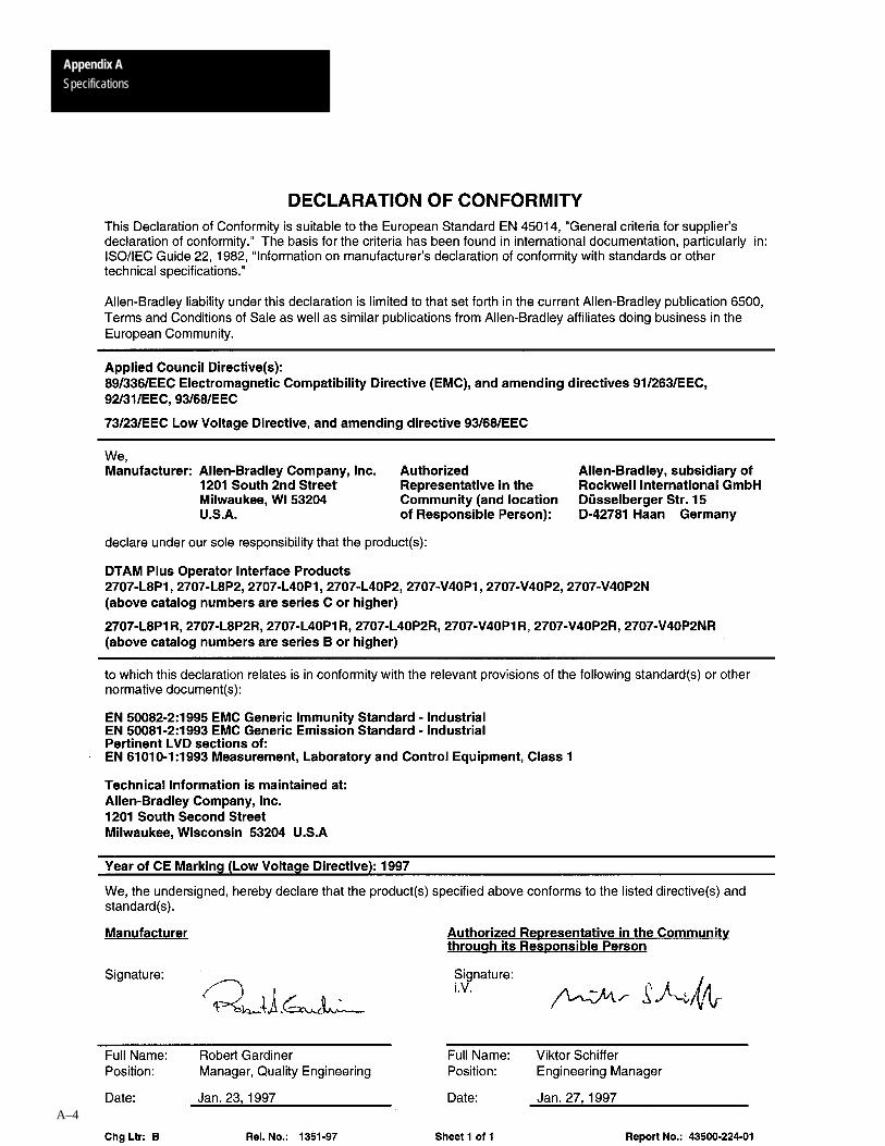
Appendix ASpecifications
A–4

A–B BAppendix
B–1
DTAM Plus Cable Diagrams
Catalog No. 2707-NC1
Use the DH-485 Network Interface Cable to connect the RS-232/RS-485versions of the DTAM Plus to an SLC DH-485 network.
DTAM Plus RS-485Comm Port
SLC 500 Programming Port orIsolated Link Coupler Peripheral Port
8-Pin Male RJ ConnectorAMP#5-55179-X9-Pin Male D Connector
1
2
3
4
5
6
7
8
9
1
2
3
4
5
6
7
8
Data Out –
Data Out +
Data In –
Data In +
Transmit Enable
Ground
Shield
Data (CH A)
Data (CH B)
24 VDC
Gnd RS-485
Transmit Enable TX–ENShield
Gnd RS-485
24 VDC
Catalog No. 2707-NC2
Use the Upload/Download Cable to connect the RS-232/RS-485 versions ofthe DTAM Plus to a personal computer for transferring applications. A 25 to9 pin adapter is required if your computer has a 25 pin communication port.
DTAM Plus RS-232Comm Port
Data In
Data Out
Signal Ground
Data In
Data Out
Signal Ground
1
2
3
4
5
1
2
3
4
5
Computer 9 PinSerial Port (COM1, COM2)
9-Pin Male D Connector 9-Pin Female D Connector
DTAM Plus Cables

Appendix BDTAM Plus Cable Diagrams
B–2
Catalog No. 2707-NC3
Use the RS-232 Communications Cable to connect the RS-232/RS-485versions of the DTAM Plus to Channel 0 (configured as RS-232) of a PLC-5.
Data In
Signal Ground
2
3
5
2
3
7
4
5
6
8
DTAM Plus RS-232Comm Port
PLC-5 Channel 0 Port
RTSCTS
DSR
DCD
DTR20
Data Out
9-Pin Male D Connector
25-Pin Male D Connector
RS-232
Data Out
Signal Ground
Data In
Handshake lines onlyrequired if Handshake is enabled in PLC.
Catalog No. 2707-NC4
Use the RS-422 Communications Cable to connect the RS-485 Comm portof the DTAM Plus to Channel 0 (configured as RS-422) of a PLC-5. TheDTAM Plus RS-485 port is compatible with the PLC-5 RS-422 standard.
DTAM Plus RS-485Comm Port
Data Out –Data Out +
Data In –Data In +
Signal Ground
1
2
3
4
5
2
14
3
16
7
6
8
20
4
PLC-5 Channel 0 Port
5
13
19
25-Pin Male D Connector
9-Pin Male D Connector
RS-422
DTR
Data Out +
Data In –
Data In +
Signal Ground
DSR
DCD
Data Out –
RTS +
CTS +
CTS –
RTS –
Handshake lines onlyrequired if Handshake is enabled in PLC.

Appendix BDTAM Plus Cable Diagrams
B–3
Catalog No. 2707-NC6
Use the ASCII Input cable to connect an ASCII device to the DTAM Plusprinter port. Use this cable with decoded bar code scanners.
RS-232C 9-Pin2 = Data Out3 = Data In5 = Signal Ground
1
2
3
4
5
1
2
3
4
5
6
7
DTAM Plus RS-232C 9 Pin2 = Data In3 = Data Out5 = Signal Ground
DTAM Plus RS-232CPrinter Port
➀ RS-232 Synapse InterfaceCable
= Female Connector= Male Connector
➀ The communications port of the DTAM Plus must be set to RS-232.

Appendix BDTAM Plus Cable Diagrams
B–4
Catalog No. 2707-NC10
Use the RS-232 Communications cable (Catalog No. 2707-NC10) to connectthe DTAM Plus to the MicroLogix 1000 for run-time operation. The lengthof this cable is 2 meters.
Data In
Data Out
Signal Ground
1
2
3
4
5
1
2
3
4
5
9-Pin Male D Connector
Connects to MicroLogix 1000Communications Port
8-Pin Male C DIN Right Angle Connector
6
7
8
Data In (RXD)
Data Out (TXD)
5 4 3 2 1
9 8 7 6
7 86
1 2
53
4
DC Com
6
7
8
9
Connects to DTAM Plus RS-232Communications Port

Appendix BDTAM Plus Cable Diagrams
B–5
Catalog No. 1747-CP3
Use this RS-232 Communications Cable to connect the RS-232 Comm portof the DTAM Plus to Channel 0 of an SLC 5/03, 5/04. A 9 pin male tofemale gender adapter is required when using this cable. If you are makingyour own cable, use a 9 pin male connector on the DTAM Plus end instead ofthe 9 pin female connector (with 90� bend allowing closure of the SLC door)shown below. In addition, the control lines are not needed.
DTAM Plus RS-232Comm Port
CDRXD
TXDDTR
1
2
3
4
5
9-Pin Female D Connector
6
7
8
9
COMMON
DSR
RTS
CTS
RI
CDRXD
TXDDTR
1
2
3
4
5
6
7
8
9
COMMON
DSR
CTS
RTS
RI
9-Pin Female D Connector
SLC 5/03 Channel 0 PortRS-232
Note: A gender adapter is required whenusing the 1747-CP3 cable. If you arecreating your own cable, use a maleconnector on the DTAM Plus end.
= Not used for DTAM Plus
The control lines (pins #1, #4, #6, #7, and #8) are not used by the DTAMPlus. The connections to these pins can be deleted for this application.

Appendix BDTAM Plus Cable Diagrams
B–6
DTAM Plus RS-232 Printer Port Cable
Create the following cable for the optional printer port of the DTAM Plus.Use this port to send data to a printer or serial device such as a large display.
= Male Connector
DTAM Plus RS-232Printer Port
RS-232 Printer
DTAM Plus RS-232 9 Pin3 = Data Out 5 = Signal Ground7 = Request to Send8 = Clear to Send
RS-232 9 Pin2 = Data In5 = Signal Ground7 = Request to Send8 = Clear to Send
or Serial Device
= Female Connector=
1
2
3
4
5
6
7
8
9
1
2
3
4
5
6
7
8
9
RS-232 25 Pin3 = Data In4 = Request to Send5 = Clear to Send7 = Signal Ground
or ➀
➀ Use this pinout if printer or serial device has a 25 pin connector.

A–B CAppendix
C–1
Special Controller Functions
This appendix describes the Special Menu used to access to special featuresfor controller operations.
Section Page
Accessing Special Functions C–2
Using the P-A/D Function C–3
Reading Controller Input and Output Files C–4
Reading / Writing Controller Status Files C–5
Reading / Writing Controller Bit and Integer Files C–6
Reading / Writing Controller Timer Files C–7
Reading / Writing Controller Counter Files C–8
Reading / Writing Controller Control Files C–9
Reading / Writing Floating Point Files C–10
Reading / Writing Controller ASCII Files C–11
Reading / Writing Controller BCD Files C–12
Reading / Writing Controller Block Transfer Files C–13
Reading / Writing Controller Message Files C–14
Reading / Writing PID Files C–15
Reading / Writing SFC Files C–16
Reading Controller ASCII String Files C–17
Using the Mode Function C–19
Using the Memory Transfer Function C–20
Using the Clear Fault Function C–21
Objectives

Special Controller Functions
Appendix C
C–2
To access the Special Functions Menu:
1. Select item 5 from the Function Menu to access the Special Menu:
1 C-Port 5 Special2 P-Port 6 Term3 Clk/Cal 7 Test4 Reset 8 Other
You are prompted:
SLC 50X Network AddrPress
”Y’ to Edit Address”N” to Bypass
1. P – A/D2. R – PORT
Remote I/OOperating System
PLC-5 DF1Operating System
DH485Operating System
DTAMPlus:00 Max:02SLC Expected At 01Input NewSLC Node 01 Press ENTER
1. P – A/D2. SLC 50X Mode3. Memory Transfer4. Clear SLC Fault
1. P – A/D2. PLC Mode3. Memory Transfer4. Clear PLC Fault
2. The special functions you can select depends upon the the operatingsystem.
The Special Menu provides access to one or more of these functions:
1 P-A/D refer to page C–3 for more information.
2 Mode (DH485 or PLC-5 DF1) refer to page C–19 for more information.
2 R Port (Remote I/O) refer to Chapter 3 for more information.
3 Mem Xfer refer to page C–20 for more information.
4 Clr Fault refer to page C–21 for more information.
Accessing SpecialFunctions

Special Controller FunctionsAppendix C
C–3
Use the P-A/D function to display and change values in controller files. Theonly exceptions are Input and Output files, you cannot write to these filetypes. The P-A/D function is often useful when starting up or debuggingapplications. The following tables list the controller file types that can beaccessed using the P-A/D function:
SLC File Types PLC File Types
File Type Identifier Default File Number Read Write File Type Identifier Default
File Number Read Write
Output O 0 Yes No Output O 0 (fixed) Yes No
Input � 1 Yes No Input � 1 (fixed) Yes No
Status S 2 Yes Yes Status S 2 (fixed) Yes Yes
Binary B 3 Yes Yes Binary B 3 Yes Yes
Timer T 4 Yes Yes Timer T 4 Yes Yes
Counter C 5 Yes Yes Counter C 5 Yes Yes
Control R 6 Yes Yes Control R 6 Yes Yes
Integer N 7 Yes Yes Integer N 7 Yes Yes
ASCII➀ A None Yes No Floating Point F 8 Yes Yes
ASCII String➀ ST None Yes No ASCII A 9 Yes Yes
Floating Point➀ F None Yes Yes BCD D 10 Yes Yes
➀ Not supported by SLC 5/01 or 5/02 controllers. Block Transfer BTR orBTW
11 Yes Yes
Message MG 12 Yes No
PID PD 13 Yes Yes
SFC SC 14 Yes Yes
ASCII String ST 15 Yes No
Using the P-A/D Function

Special Controller Functions
Appendix C
C–4
To read the contents of controller Input and Output files:
1. Enter the P–A/D function from the Special Menu.
You are prompted for a file type:
Select file type:(O)OutputPREV/NEXT To ScrollENTER To Select
2. Press [NEXT] and [PREV] keys to scroll through the file types. Select either (I)Input or (O)Output and press [ ].
You are prompted:
(0) Output
Element Addr: 0
Remote I/OOperating System
PLC-5 DF1Operating System
DH485Operating System
Select File Number0Press ENTER
File Number0Word Address: 0
File Number: 0
Element Addr: 0
3. Enter the Element Address (PLC) or the File Number and Word Address(SLC) If you are accessing PLC data, you must enter an octal value.
You are shown the value at that address:
File:Elem DEC HEXO001:000 00000 000015 .... Binary ... 00000 0000 0000 0000
Remote I/OOperating System
DH485, PLC-5 DF1Operating Systems
File:Elem DEC HEXO :000 00000 000015 .... Binary ... 00000 0000 0000 0000
4. Press the [NEXT] key to enter a new element address. Press [ ] todisplay the contents at the new address.
5. Pressing the [PREV MENU] key at any time returns to the P–A/D fileselect menu.
Reading Controller Input andOutput Files

Special Controller FunctionsAppendix C
C–5
To read/write the contents of controller Status files:
!ATTENTION: Changing control status bits may cause aprocessor fault or have other possible effects on the controlleroperation. Make sure you understand the function of status data.
1. Enter the P–A/D function from the Special Menu.
You are prompted for a file type:
Select file type:(O)OutputPREV/NEXT To ScrollENTER To Select
2. Press [NEXT] and [PREV] keys to scroll through the file types. Select (S)Status and press [ ].
You are prompted for a status file number:
Select File Number2Press ENTER
PLC-5 DF1Operating System
DH485Operating System
File Number: 2
Element Addr: 0
File Number2Word Address: 0
3. Enter the status file number and word or element address.
You are shown the value at that address:
File:Elem DEC HEXS002:000 00000 000015 .... Binary ... 00000 0000 0000 0000
PLC-5 DF1Operating System
DH485Operating System
File:Word DEC HEXS002:000 00000 000015 .... Binary ... 00000 0000 0000 0000
4. To change a value or the element address, move the cursor into the datafield using the [NEXT] or [PREV] keys. Enter the new data. If you areediting binary data, use the [+/-] key to toggle the data between 1 and 0and press [NEXT] or [PREV] to move to the next bit. See Attention above.
5. Press [ ] to to load the new data into the file element.
6. Pressing the [PREV MENU] key at any time returns to the P–A/D fileselect menu.
Reading / Writing ControllerStatus Files
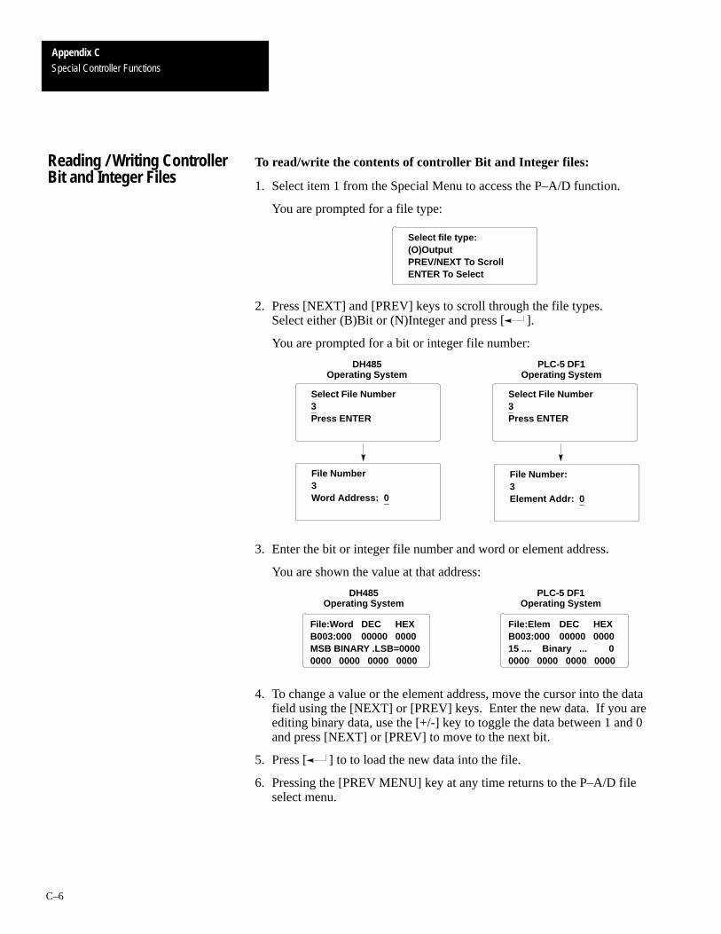
Special Controller Functions
Appendix C
C–6
To read/write the contents of controller Bit and Integer files:
1. Select item 1 from the Special Menu to access the P–A/D function.
You are prompted for a file type:
Select file type:(O)OutputPREV/NEXT To ScrollENTER To Select
2. Press [NEXT] and [PREV] keys to scroll through the file types. Select either (B)Bit or (N)Integer and press [ ].
You are prompted for a bit or integer file number:
Select File Number3Press ENTER
File Number3Word Address: 0
File Number: 3Element Addr: 0
PLC-5 DF1Operating System
DH485Operating System
Select File Number3Press ENTER
3. Enter the bit or integer file number and word or element address.
You are shown the value at that address:
File:Word DEC HEXB003:000 00000 0000MSB BINARY .LSB=00000000 0000 0000 0000
File:Elem DEC HEXB003:000 00000 000015 .... Binary ... 00000 0000 0000 0000
PLC-5 DF1Operating System
DH485Operating System
4. To change a value or the element address, move the cursor into the datafield using the [NEXT] or [PREV] keys. Enter the new data. If you areediting binary data, use the [+/-] key to toggle the data between 1 and 0and press [NEXT] or [PREV] to move to the next bit.
5. Press [ ] to to load the new data into the file.
6. Pressing the [PREV MENU] key at any time returns to the P–A/D fileselect menu.
Reading / Writing ControllerBit and Integer Files

Special Controller FunctionsAppendix C
C–7
To read/write the contents of controller Timer files:
1. Select item 1 from the Special Menu to access the P–A/D function.
You are prompted for a file type:
Select file type:(O)OutputPREV/NEXT To ScrollENTER To Select
2. Press [NEXT] and [PREV] keys to scroll through the file types. Select (T)Timer and press [ ].
You are prompted for a timer file number:
Select File Number4Press ENTER
File Number4Word Address: 0
File Number: 4Element Addr: 0
PLC-5 DF1Operating System
DH485Operating System
Select File Number4Press ENTER
3. Enter the timer file number and word or element address.
You are shown the timer data:
T004:000 Acc 00000Pre 00000
EN TT DN0 0 0
Bits(Enable, Timer Timing,Done)
4. To change the Acc and Pre values or element address, move the cursor tothe data field using the [PREV] or [NEXT] keys. Enter the new data.
!ATTENTION: Do not send negative timer values to thecontroller. Negative timer values can cause a controller fault.
5. Press the [ ] key to enter new accumulator or preset values to thedisplayed timer address.
6. Pressing the [PREV MENU] key at any time returns to the P–A/D fileselect menu.
Reading / Writing ControllerTimer Files

Special Controller Functions
Appendix C
C–8
To read/write the contents of controller Counter files:
1. Select item 1 from the Special Menu to access the P–A/D function.
You are prompted for a file type:
Select file type:(O)OutputPREV/NEXT To ScrollENTER To Select
2. Press [NEXT] and [PREV] keys to scroll through the file types. Select (C) Counter and press [ ].
You are prompted for a counter file number:
Select File Number5Press ENTER
File Number5Word Address: 0
File Number: 5Element Addr: 0
PLC-5 DF1Operating System
DH485Operating System
Select File Number5Press ENTER
3. Enter the counter file number and word or element address.
You are shown the value at that address:
C005:000 Acc 00000Pre 00000
CU Cd DN OV UN0 0 0 0 0
Bits(Count Up Enable,Count Down EnableDoneOverflowUnderflow)
4. To change the Acc and Pre values or element address, move the cursor tothe data field using the [PREV] or [NEXT] keys. Enter the new data.
5. Press the [ ] key to enter new accumulator or preset values to thedisplayed counter address.
6. Pressing the [PREV MENU] key at any time returns to the P–A/D fileselect menu.
Reading / Writing ControllerCounter Files

Special Controller FunctionsAppendix C
C–9
To read/write the contents of controller Control files:
1. Select item 1 from the Special Menu to access the P–A/D function.
You are prompted for a file type:
Select file type:(O)OutputPREV/NEXT To ScrollENTER To Select
2. Press [NEXT] and [PREV] keys to scroll through the file types. Select (R)Control and press [ ].
You are prompted for a control file number:
Select File Number6Press ENTER
File Number6Word Address: 0
File Number: 6Element Addr: 0
PLC-5 DF1Operating System
DH485Operating System
Select File Number6Press ENTER
3. Enter the control file number and word or element address.
You are shown the value at that address:
R006:000 Len 00000Pos 00000
EnEu DnEm ERUl InFd0 0 0 0 0 0 0 0
Bits(Enable, Enable UnloadDone, EmptyError, UnloadInhibit, Found)
PLC-5 DF1Operating System
DH485Operating System
R006:000 Len 00000Pos 00000
EN DN ER Ul IN0 0 0 0 0
Bits(EnableDoneErrorUnloadInhibit)
4. To change the Len and Pos values or element address, move the cursor tothe data field using the [PREV] or [NEXT] keys. Enter the new data.
5. Press the [ ] key to enter new length or position values to thedisplayed control address.
6. Pressing the [PREV MENU] key at any time returns to the P–A/D fileselect menu.
Reading / Writing ControllerControl Files

Special Controller Functions
Appendix C
C–10
To read the contents of Floating Point files:
1. Select item 1 from the Special Menu to access the P–A/D function.
You are prompted for a file type:
Select file type:(O)OutputPREV/NEXT To ScrollENTER To Select
2. Press [NEXT] and [PREV] keys to scroll through the file types. Select (F)Float and press [ ].
You are prompted for a floating point file number:
File Number: 8Element Addr: 0
PLC-5 DF1, DH-485Operating Systems
Select File Number8Press ENTER
3. Enter the floating point file number and word or element address.
You are shown the value at that address:
File:Elem: F008:000
Float0.
4. To change the floating point value or element address, move the cursor tothe data field using the [PREV] or [NEXT] keys. Enter the new data.
5. Press the [ ] key to enter new length or position values to thedisplayed floating point address.
6. Pressing the [PREV MENU] key at any time returns to the P–A/D fileselect menu.
Reading / Writing FloatingPoint Files

Special Controller FunctionsAppendix C
C–11
To read the contents of ASCII files:
1. Select item 1 from the Special Menu to access the P–A/D function.
You are prompted for a file type:
Select file type:(O)OutputPREV/NEXT To ScrollENTER To Select
2. Press [NEXT] and [PREV] keys to scroll through the file types. Select (A)ASCII and press [ ].
You are prompted for an ASCII file number:
File Number: 9Element Addr: 0
PLC-5 DF1, DH485Operating Systems
Select File Number9Press ENTER
3. Enter the ASCII file number and word or element address.
You are shown the value at that address:
File:Elem ASCIIA003:000 ,00, 0015 .... Binary ... 00000 0000 0000 0000
4. To change a value or the element address, move the cursor into the datafield using the [NEXT] or [PREV] keys. Enter the new data. If you areediting binary data, use the [+/-] key to toggle the data between 1 and 0and press [NEXT] or [PREV] to move to the next bit.
5. Press [ ] to to load the new data into the file.
6. Pressing the [PREV MENU] key at any time returns to the P–A/D fileselect menu.
Reading / Writing ControllerASCII Files

Special Controller Functions
Appendix C
C–12
To read/write the contents of controller BCD files:
1. Select item 1 from the Special Menu to access the P–A/D function.
You are prompted for a file type:
Select file type:(O)OutputPREV/NEXT To ScrollENTER To Select
2. Press [NEXT] and [PREV] keys to scroll through the file types. Select (D)BCD and press [ ].
You are prompted for a BCD file number:
File Number: 10Element Addr: 0
PLC-5 DF1Operating System
Select File Number10Press ENTER
3. Enter the BCD file number and word or element address.
You are shown the value at that address:
File:Elem DEC BCDB003:000 00000 000015 .... Binary ... 00000 0000 0000 0000
4. To change a value or the element address, move the cursor into the datafield using the [NEXT] or [PREV] keys. Enter the new data. If you areediting binary data, use the [+/-] key to toggle the data between 1 and 0and press [NEXT] or [PREV] to move to the next bit.
5. Press [ ] to to load the new data into the file.
6. Pressing the [PREV MENU] key at any time returns to the P–A/D fileselect menu.
Reading / Writing ControllerBCD Files

Special Controller FunctionsAppendix C
C–13
To read/write the contents of PLC controller Block Transfer Read or Write files:
1. Select item 1 from the Special Menu to access the P–A/D function.
You are prompted for a file type:
Select file type:(O)OutputPREV/NEXT To ScrollENTER To Select
2. Press [NEXT] and [PREV] keys to scroll through the file types. Select (BT, BTR, or BTW) Block Xfer and press [ ].
You are prompted for a block transfer file number:
File Number: 11Element Addr: 0
PLC-5 DF1 Operating System
Select File Number11Press ENTER
File Number: 11Element Addr: 0Sub-Element Addr: 0
Remote I/O Operating System
(BTR)Block Transfer Read
Element Addr: 0
3. Enter the block transfer file number and word or element / sub-element address.
You are shown the value at that address:
File:Elem: SElem DECBT011:000:00 00 00015 .... Binary ... 00000 0000 0000 0000
PLC-5 DF1 Operating System
Remote I/O Operating System
File:Elem: DEC HexBTR :000 00 000 000015 .... Binary ... 00000 0000 0000 0000
4. To change a value, element, or sub-element address, move the cursor intothe data field using the [NEXT] or [PREV] keys. Enter the new data. Ifyou are editing binary data, use the [+/-] key to toggle the data between 1and 0 and press [NEXT] or [PREV] to move to the next bit.
5. Press [ ] to to load the new data into the file.
6. Pressing the [PREV MENU] key at any time returns to the P–A/D fileselect menu.
Reading / Writing ControllerBlock Transfer Files

Special Controller Functions
Appendix C
C–14
To read the contents of PLC message files:
1. Select item 1 from the Special Menu to access the P–A/D function.
You are prompted for a file type:
Select file type:(O)OutputPREV/NEXT To ScrollENTER To Select
2. Press [NEXT] and [PREV] keys to scroll through the file types. Select (MG)Message and press [ ].
You are prompted for a message file number:
File Number: 12Element Addr: 0
PLC-5 DF1Operating System
Select File Number12Press ENTER
File Number: 12Element Addr: 0Sub–Element Addr: 0
3. Enter the message file number and word or element / sub-element address.
You are shown the value at that address:
File:Elem: SElem DECMG012:000:00 000015 .... Binary ... 00000 0000 0000 0000
4. To change a value, element, or sub-element address, move the cursor intothe data field using the [NEXT] or [PREV] keys. Enter the new data. Ifyou are editing binary data, use the [+/-] key to toggle the data between 1and 0 and press [NEXT] or [PREV] to move to the next bit.
5. Press [ ] to to load the new data into the file.
6. Pressing the [PREV MENU] key at any time returns to the P–A/D fileselect menu.
Reading / Writing ControllerMessage Files

Special Controller FunctionsAppendix C
C–15
To read the contents of PLC PID files:
1. Select item 1 from the Special Menu to access the P–A/D function.
You are prompted for a file type:
Select file type:(O)OutputPREV/NEXT To ScrollENTER To Select
2. Press [NEXT] and [PREV] keys to scroll through the file types. Select (PD)PID and press [ ].
You are prompted for a PID file number:
File Number: 13Element Addr: 0
PLC-5 DF1Operating System
Select File Number13Press ENTER
File Number: 13Element Addr: 0Sub–Element Addr: 0
3. Enter the PID file number and word or element / sub-element address.
You are shown the value at that address:
File:Elem: SElem DECPD013:000:00 0000015 .... Binary ... 00000 0000 0000 0000
4. To change a value, element, or sub-element address, move the cursor intothe data field using the [NEXT] or [PREV] keys. Enter the new data. Ifyou are editing binary data, use the [+/-] key to toggle the data between 1and 0 and press [NEXT] or [PREV] to move to the next bit.
5. Press [ ] to to load the new data into the file.
6. Pressing the [PREV MENU] key at any time returns to the P–A/D fileselect menu.
Reading / Writing PID Files

Special Controller Functions
Appendix C
C–16
To read the contents of PLC SFC files:
1. Select item 1 from the Special Menu to access the P–A/D function.
You are prompted for a file type:
Select file type:(O)OutputPREV/NEXT To ScrollENTER To Select
2. Press [NEXT] and [PREV] keys to scroll through the file types. Select (MG)Message and press [ ].
You are prompted for an SFC file number:
File Number: 14Element Addr: 0
PLC-5 DF1Operating System
Select File Number14Press ENTER
3. Enter the SFC file number and word or element address.
You are shown the value at that address:
SC014:000 Pre00000Tim 00000
SA FS LS OV ER DN0 0 0 0 0 0
4. To change a value or element address, move the cursor into the data fieldusing the [PREV] and [NEXT] keys. Enter the new data.
5. Press [ ] to to load the new data into the file.
6. Pressing the [PREV MENU] key at any time returns to the P–A/D fileselect menu.
Reading / Writing SFC Files

Special Controller FunctionsAppendix C
C–17
To read the contents of PLC ASCII string files:
1. Select item 1 from the Special Menu to access the P-A/D function.
You are prompted for a file type:
Select file type:(O)OutputPREV/NEXT To ScrollENTER To Select
2. Press [NEXT] and [PREV] keys to scroll through the file types. Select (ST)ASCII Str and press [ ].
You are prompted for a message file number:
File Number: 15Element Addr: 0
PLC-5 DF1, DH-485Operating Systems
Select File Number15Press ENTER
File Number: 15Element Addr: 0Starting Char: 0
3. Enter the ASCII string file number, word or element address and thestarting (1 to 81). The starting character specifies the first character in thestring to be displayed followed by the remaining characters (up to the82nd character).
Note: In order to maintain boundary addressing, only odd startingcharacters are allowed. If an even value is entered the DTAM Plus willchange the value down to the next lower odd number.
You are shown the value beginning at the starting character:
ST015:000.00 Len 00XXXXXXXXXXXXXXXXXXXXXXXXXXXXXXXXXXXXXXXXXXXXX
The Len field displays the string length in a decimal format. Up to 60characters of the string are displayed on lines 2, 3, and 4. Strings longerthan 60 characters are truncated.
Reading Controller ASCIIString Files

Special Controller Functions
Appendix C
C–18
4. To change an element address, move the cursor into the data field usingthe [NEXT] or [PREV] keys. Enter the new data.
5. Press [ ] to to display the data at the new address.
6. Pressing the [PREV MENU] key at any time returns to the P–A/D fileselect menu.

Special Controller FunctionsAppendix C
C–19
Use the Mode function to change the controller operating mode (Run orProgram) from the DTAM Plus. The mode function displays for an SLC andPLC operating system are different. Both are shown below:
SLC Controllers
1. Select item 2 from the Special Menu to access the Mode function.
You are prompted for an operating mode:
SLC 50X ModePress”Y” to RUN”N” to PROGRAM
2. Press [Y] to place the controller in Run mode or [N] to enter the Programmode.
You are returned to the Main Menu.
PLC Controllers
1. Select item 2 from the Special Menu to access the Mode function.
The PLC must be in Remote Program mode or you will be prompted:
PLC not in Remote modePress ”Y” to continue
2. Depending upon the current PLC mode, you are prompted to change thecontroller mode:
If the controller is in Run mode: If the controller is in Program mode;
PLC is in Run ModeY=Prog N=Abort
PLC is in PROG ModeY=RUN N=Abort
3. Press [Y] or [N] to enter your selection.
You are returned to the Main Menu.
Using the Mode Function

Special Controller Functions
Appendix C
C–20
The Memory Transfer function allows the DTAM Plus to initiate a memorytransfer between a controller memory module and the controller.
• Memory transfers with an SLC are bidirectional. Data can be transferredto and from the memory module.
• PLC transfers are only from the PLC to the memory module.
SLC Controllers1. Select item 3 from the Special Menu to access the Mem Xfer function.
You are prompted for a transfer direction:
Memory TransferPress”Y” SLC � MEM Pack”N” MEM PAC � SLC
2. Place the memory module into the SLC. The SLC must be in theprogram mode.
3. Press [Y] to transfer data (ladder program and data files) from the SLC tothe memory module.Press [N] to transfer data from the memory module to the SLC.
You are returned to the Main Menu.
PLC Controllers1. Select item 2 from the Special Menu to access the Mem Xfer function.
The PLC must be in Program or Remote Program mode or you will beprompted:
Not in Programor RemoteModePress ”Y” to continue
You are prompted to continue the operation:
Press ”Y” to transferfrom PLC memoryto the module
2. Place the memory module into the PLC.
3. Press [Y] to transfer data from the PLC to the memory module. Press [N] to abort the operation.
The DTAM Plus will display either:
EEPROMSuccessfully BurnedPress ”Y” to continue
ERROREEPROM NOT BURNEDPress ”Y” to continue
Using the Memory TransferFunction

Special Controller FunctionsAppendix C
C–21
Use the Clear Fault function to clear all major and minor faults in the logiccontroller.
To clear controller faults:
1. If you are clearing a PLC, the controller must be in Program or RemoteProgram mode.
2. Select item 4 from the Special Menu to access the Clear Fault function.
You are prompted to clear faults:
Clear SLC FaultPress ”Y”To Clear All SLC 50X FaultsPress ”N” To Exit
Press ”Y”To Clear All PLC 5 FaultsPress ”N” To Exit
SLC Controllers PLC Controllers
3. Press [Y] to clear the faults or [N] to abort the function.
The faults are cleared and you are returned to the special functions menu:
Using the Clear FaultFunction

A–B DAppendix
D–1
Terminal Mode
When using the DTAM Plus in terminal mode, the keypad is mapped to thecharacters shown in the following table.
DTAM Plus Key ASCII HEX Decimal
Main Menu . . . . . . . . . . . . . . . 85 133
Prev Menu . . . . . . . . . . . . . . . 84 132
Prev . . . . . . . . . . . . . . . . . . . . 82 130
Next . . . . . . . . . . . . . . . . . . . . 80 128
*F . . . . . . . . . . . . . . . . . . . . . . 86 134
*Contrast (Half Ball) . . . . . . . 83 131
*Backlight (Sun) . . . . . . . . . . 81 129
Y . . . . . . . . . . . . . . . . Y 59 89
N . . . . . . . . . . . . . . . . N 4E 78
Back Space . . . . . . . . <BS> 8 8
EXP . . . . . . . . . . . . . E 45 69
CE . . . . . . . . . . . . . . <FF> 0C 12
+/– . . . . . . . . . . . . . . +/– 2B/2D 43/45
(.) . . . . . . . . . . . . . . . . 2E 46
Enter (↵ ) . . . . . . . . . <CR> D 13
9 . . . . . . . . . . . . . . . . 9 39 57
8 . . . . . . . . . . . . . . . . 8 38 56
7 . . . . . . . . . . . . . . . . 7 37 55
6 . . . . . . . . . . . . . . . . 6 36 54
5 . . . . . . . . . . . . . . . . 5 35 53
4 . . . . . . . . . . . . . . . . 4 34 52
3 . . . . . . . . . . . . . . . . 3 33 51
2 . . . . . . . . . . . . . . . . 2 32 50
1 . . . . . . . . . . . . . . . . 1 31 49
0 . . . . . . . . . . . . . . . . 0 30 48
* These keys will not transmit a code if DIP Switch SW1–5 is enabled. They will operate in their normal mode untilSW1–5 is disabled. Once SW1–5 is disabled the list codes will be transmitted.
ASCII TransmissionCharacters

Appendix DTerminal Mode
D–2
The following charts show the ASCII display characters and theircorresponding hexadecimal codes.
Table D.1Terminal Mode – Supported Display Character Set*
* All of the above characters are supported when 8 data bit communication is enabled. Hex codes below 80H aresupported by 7 data bit communication.
ASCII Display Characters
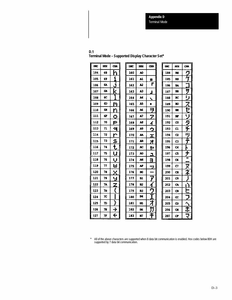
Appendix DTerminal Mode
D–3
D.1Terminal Mode – Supported Display Character Set*
* All of the above characters are supported when 8 data bit communication is enabled. Hex codes below 80H aresupported by 7 data bit communication.

Appendix DTerminal Mode
D–4
D.1Terminal Mode – Supported Display Character Set*
* All of the above characters are supported when 8 data bit communication is enabled. Hex codes below 80H aresupported by 7 data bit communication.

Appendix DTerminal Mode
D–5
Table D.2Terminal Mode – Screen Control Codes
HEX Function Description
08 BS Back Space
0A LF Line Feed
0C FF Blanks the screen, moves the cursor to the upper left corner of thedisplay.
0D CR Moves the cursor to the extreme left position of the line.
A–B EAppendix
E–1
DTAM Plus Mounting Template
Refer to the mounting template on the following page when installing theDTAM Plus.

5.625 in5.876 in
.188 in dia6 places
0.078 in
0.125 in
DTAM Plus
Panel Cut-OutTemplate
5.625 Inch x 7.725 Inch142.87 mm x 196.21 mm
7.725 in
3.938 inch = 100.03 mm7.725 inch = 196.21 mm5.625 inch = 142.87 mm
5.876 inch = 149.25 mm.188 inch = 4.78 mm0.125 inch = 3.18 mm
0.078 inch = 1.98 mm
3.938 in
3.938 in
➀ Drill holes before making the cut-out.
➁ We recommend that a minimum of 2.5” clearance be allowed for operator interface depth.
Note: Maximum panel thickness is 1/4” (.250)

DTAM Plus Operator Interface ModuleIndex
User Manual
I–1
A
Accessories, 1–13
Advisor, 4–2
Alarm LED, 1–2
Alarm Screen, 4–6
ApplicationDocumentation, 4–1Downloading, 2–8Simulation, 3–13Transfer, 2–1Uploading, 2–13
Application Files, Running, 4–1
ASCII Characters, D–1
ASCII Display Characters, D–2
ASCII File, C–11
ASCII Input, 1–1, 4–5, 6–13
ASCII String File, C–17
Audience, Intended, P–2
B
Backspace Key, 1–4
Bar Code, Scanners, 6–13
Bar Code Input, 4–5, 6–13
Baud Rate, 3–4, 3–5, 6–6Printer Port, 3–7
BCD File, C–12
Bit File, C–6
Block Transfer File, C–13
Brightness Key, 1–4
C
Cable, Diagrams, B–1
Cables, Communication, 1–13
CE Key, 1–4
Chapter Descriptions, P–1
Chart, Troubleshooting, 7–1
Cleaning Display, 7–17
Clearances, Mounting, 5–3
Clearing Faults, C–21
Clock/Caledar, Setting, 3–10
Clock/Calendar, Test, 7–15
CodesError, 7–4Master Security, 3–16
CommunicationBasic Module, 1–6Cables, 1–13Connections, 6–2, 6–3, 6–5Default Settings, 1–12DF1, 1–6Error Codes, 7–4Parameters, 1–6, 6–6Ports, 1–3Remote I/O, 1–7, 1–10RS–232, 1–6, 1–8RS–422, 1–6RS–485, 1–6, 1–9Setting Parameters, 3–4, 3–5Setting Printer Port, 3–7Upload/Download Connections, 2–6, 2–7
Communication Port, Test, 7–9
ConnectorCommunication, 6–2, 6–3, 6–5Power, 1–3, 5–7
Contrast, Setting, 3–11
Contrast Key, 1–4
Control Codes–Terminal Mode, D–5
Control File, C–9
ControllerCommunicating With, 6–6File Types, C–3Screen Changes, 4–2
Controller Mode, C–19
Conventions, P–2
Counter File, C–8
Couplers, Link, 6–4
Cursor Enable, Terminal Mode, 3–15
Cutout, Template, 5–5
D
Data Bits, 3–4, 6–6Printer Port, 3–7
Data Display Screen, 4–4
Data Entry Screen, 4–4, 4–5
Defaults, 1–11
DF1, Parameters, 1–6
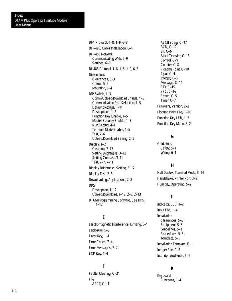
User ManualDTAM Plus Operator Interface ModuleIndex
I–2
DF1 Protocol, 1–8, 1–9, 6–3
DH–485, Cable Installation, 6–4
DH–485 NetworkCommunicating With, 6–9Settings, 6–9
DH485 Protocol, 1–6, 1–8, 1–9, 6–3
DimensionsClearances, 5–3Cutout, 5–5Mounting, 5–4
DIP Switch, 1–3Comm Upload/Download Enable, 1–5Communication Port Selection, 1–5Default Settings, 1–11Descriptions, 1–5Function Key Enable, 1–5Master Security Enable, 1–5Run Setting, 4–1Terminal Mode Enable, 1–5Test, 7–6Upload/Download Setting, 2–5
Display, 1–2Cleaning, 7–17Setting Brightness, 3–12Setting Contrast, 3–11Test, 7–7, 7–11
Display Brightness, Setting, 3–12
Display Test, 2–3
Downloading, Applications, 2–8
DPSDescription, 1–12Upload/Download, 1–12, 2–8, 2–13
DTAM Programming Software, See DPS,1–12
E
Electromagnetic Interference, Limiting, 6–1
Enclosure, 5–3
Enter Key, 1–4
Error Codes, 7–4
Error Messages, 7–2
EXP Key, 1–4
F
Faults, Clearing, C–21
FileASCII, C–11
ASCII String, C–17BCD, C–12Bit, C–6Block Transfer, C–13Control, C–9Counter, C–8Floating Point, C–10Input, C–4Integer, C–6Message, C–14PID, C–15SFC, C–16Status, C–5Timer, C–7
Firmware, Version, 2–3
Floating Point File, C–10
Function Key LED, 1–2
Function Key Menu, 3–2
G
GuidelinesSafety, 5–1Wiring, 6–1
H
Half Duplex, Terminal Mode, 3–14
Handshake, Printer Port, 3–8
Humidity, Operating, 5–2
I
Indicator, LED, 1–2
Input File, C–4
InstallationClearances, 5–3Equipment, 5–3Guidelines, 5–1Procedures, 5–6Template, 5–5
Installation Template, E–1
Integer File, C–6
Intended Audience, P–2
K
KeyboardFunctions, 1–4

DTAM Plus Operator Interface ModuleIndex
User Manual
I–3
Test, 7–8
Keypad, 1–2
L
Last Rack, 3–6
LED Indicator, 1–2
LED Indicators, A–2
Line Feed, Printer Port, 3–8
Line Feed Enable, Terminal Mode, 3–15
Link Coupler, 6–4
Links, Screen, 4–2
M
Main Menu, 4–3
Main Menu Key, 1–4
Master Security CodeDisabling, 3–16Entering, 3–16Operation, 3–17
Memory, Transfer, C–20
MenuCom–Port, 3–2Function Key, 3–2Main, 4–3Other, 3–2Printer Port, 3–2Special, 3–2Sub, 4–3Test, 3–2, 3–20, 7–5
Message File, C–14
Messages, Error, 7–2
ModeController, C–19Simulate, 3–13
Module Group, 3–6
MountingClearances, 5–3Dimensions, 5–4Equipment, 5–3Procedures, 5–6
Mounting Template, E–1
N
Next Key, 1–4
O
Operating SystemDefaults, 1–11Downloading, 6–6Options, 6–6
P
P–A/D Function, 3–19
Parity, 3–4, 6–6Printer Port, 3–8
Personal Computer, Setup, 2–7
PID File, C–15
PLC–5Communicating With, 6–6, 6–7Connections, 1–8, 1–9, 6–3Remote I/O, 1–10Remote I/O Connection, 6–5RS–232 Connection, 6–2RS–422 Connection, 6–3Settings, 6–7
Point Access/Display, C–2Description, 1–1
Port Enable, Printer Port, 3–8
PowerApplying, 2–2Connections, 2–2
Power ConnectionConnecting Power, 5–7Terminals, 5–7
Power Connector, 1–3
Power Source, 2–1
Powerup Sequence, 2–3
Prev Key, 1–4
Prev Menu Key, 1–4
Printer Port, Test, 7–10
Product Options, 1–13
Program Memory, Test, 7–14
ProtocolDF1, 1–6, 1–8, 1–9, 6–3DH485, 1–6, 1–8, 1–9, 6–3Remote I/O, 1–7, 1–10
PublicationsDTAM Micro, P–3PLC–5, P–3SLC, P–3Wiring, P–3

User ManualDTAM Plus Operator Interface ModuleIndex
I–4
R
Rack Number, 3–6
Rack Size, 3–5
RAM, Test, 7–12
Recipe, Description, 1–1
Recipe Screen, 4–6
Related Publications, P–3
Remote I/OCabling, 1–13Communication Port, 1–7Communications, 1–10Connections, 6–5Setting Parameters, 3–5Subscanner, 1–10
Reset, 3–3, 3–6
RS–232Connections, 6–2Port, 1–3
RS–485Connections, 6–3Port, 1–3
Run LED, 1–2
S
Safety, Guidelines, 5–1
Scaling, Enable/Disable, 3–18
ScreenAlarm, 4–6Data Display, 4–4Data Entry, 4–4, 4–5Main Menu, 4–3Navigation, 4–2Recipe, 4–6Security, 4–3Sub–Menu, 4–3Types, 4–2
Screen Changes, Controller, 4–2
Screen Links, 4–2
Screen Prints, Enable/Disable, 3–9
Security Code, 4–3Master, 3–16
Security Screen, 4–3
SFC File, C–16
Simulate Mode, 3–13
SLCCommunicating With, 6–9Settings, 6–9
SLC 5/03Communicating With, 6–8Connections, 1–8, 1–9, 6–3Remote I/O, 1–10Remote I/O Connection, 6–5RS–232 Connection, 6–2RS–485 Connection, 6–3Settings, 6–8
Specifications, A–1, C–1, D–1
Status File, C–5
Sub–Menus, 4–3
Subscanner, Remote I/O, 1–10
System Memory, Test, 7–13
T
Temperature, Operating, 5–2
Template, E–1Cutout, 5–5
Terminal ModeCursor Enable, 3–15Enabling, 3–14Line Feed, 3–15Setting Parameters, 3–14
Terminal Mode Control Codes, D–5
TestClock/Calendar, 7–15Communication Port, 7–9DIP Switch, 7–6Display, 2–3, 7–7Display Control, 7–11Functions, 3–20, 7–5Keyboard, 7–8Memory, 2–4Printer Port, 7–10Program Memory, 7–14RAM, 7–12System Memory, 7–13Transmit Enable, 7–16
Test Menu, 3–20
Timer File, C–7
Transmit Enable, Test, 7–16
Troubleshooting, 7–1Chart, 7–1Equipment, 7–1
U
Upload/DownloadConnections, 2–6, 2–7

DTAM Plus Operator Interface ModuleIndex
User Manual
I–5
DIP Switch Settings, 2–5
Uploading, Applications, 2–13
V
Voltage, Ratings, 2–1
W
Wildcard Character, 3–17

Rockwell Automation helps its customers receive a superior return on their investment by bringingtogether leading brands in industrial automation, creating a broad spectrum of easy-to-integrateproducts. These are supported by local technical resources available worldwide, a global networkof system solutions providers, and the advanced technology resources of Rockwell.
Worldwide representation.Argentina • Australia • Austria • Bahrain • Belgium • Bolivia • Brazil • Bulgaria • Canada • Chile • China, People’s Republic of • Colombia • Costa Rica • Croatia • CyprusCzech Republic • Denmark • Dominican Republic • Ecuador • Egypt • El Salvador • Finland • France • Germany • Ghana • Greece • Guatemala • Honduras • Hong KongHungary • Iceland • India • Indonesia • Iran • Ireland • Israel • Italy • Jamaica • Japan • Jordan • Korea • Kuwait • Lebanon • Macau • Malaysia • Malta • Mexico • MoroccoThe Netherlands • New Zealand • Nigeria • Norway • Oman • Pakistan • Panama • Peru • Philippines • Poland • Portugal • Puerto Rico • Qatar • Romania • Russia • SaudiArabia • Singapore • Slovakia • Slovenia • South Africa, Republic of • Spain • Sweden • Switzerland • Taiwan • Thailand • Trinidad • Tunisia • Turkey • United Arab EmiratesUnited Kingdom • United States • Uruguay • Venezuela
Rockwell Automation Headquarters, 1201 South Second Street, Milwaukee, WI 53204-2496 USA, Tel: (1) 414 382-2000 Fax: (1) 414 382-4444Rockwell Automation European Headquarters, Avenue Hermann Debroux, 46, 1160 Brussels, Belgium, Tel: (32) 2 663 06 00, Fax: (32) 2 663 06 40Rockwell Automation Asia Pacific Headquarters, 27/F Citicorp Centre, 18 Whitfield Road, Causeway Bay, Hong Kong, Tel: (852) 2887 4788, Fax: (852) 2508 1846World Wide Web: http://www.ab.com
Publication 2707-800 – June 1999Supersedes Publication 2707-800 – November 1994
Supersedes Publication 2707-800.4 – January 1997
40062-265-01(D)Copyright 1999 Allen-Bradley Company, Inc. Printed in USA