27cx01b - epanorama 27cx01b.pdf · output rating ..... 1.3w + 1.3w (at 10% distortion and dual ch...
TRANSCRIPT

1
» ELECTRICAL SPECIFICATIONS .........................................................................................................1» IMPORTANT SERVICE SAFETY PRECAUTION .................................................................................2» LOCATION OF USER'S CONTROL .....................................................................................................6» INSTALLATION AND SERVICE INSTRUCTIONS ................................................................................7» CHASSIS LAYOUT .............................................................................................................................13» BLOCK DIAGRAM ..............................................................................................................................14» SCHEMATIC DIAGRAMS ...................................................................................................................15» PRINTED WIRING BOARD ASSEMBLIES ........................................................................................22» REPLACEMENT PARTS LIST ............................................................................................................25» PACKING OF THE SET ......................................................................................................................33
Page
POWER INPUT .................................................... 120 V AC 60 Hz
POWER RATING .................................................................. 110 W
PICTURE SIZE ........................................... 2,187cm2 (339sq inch)
CONVERGENCE ............................................................. Magnetic
SWEEP DEFLECTION .................................................... Magnetic
FOCUS ............................................... Hi-Bi-Potential Electrostatic
INTERMEDIATE FREQUENCIES
Picture IF Carrier Frequency ..................................... 45.75 MHz
Sound IF Carrier Frequency ...................................... 41.25 MHz
Color Sub-Carrier Frequency .................................... 42.17 MHz
(Nominal)
AUDIO POWER
OUTPUT RATING .............. 1.3W + 1.3W (at 10% distortion and
Dual CH Operate)
CONTENTS
ELECTRICAL SPECIFICATIONSSPEAKER
SIZE ...................................................................... 8 cm (Round)
VOICE COIL IMPEDANCE ............................ 32 ohm at 400 Hz
ANTENNA INPUT IMPEDANCE
VHF/UHF ..................................................... 75 ohm Unbalanced
TUNING RANGES
VHF-Channels ............................................................... 2 thru 13
UHF-Channels ............................................................ 14 thru 69
CATV Channels ........................................................... 1 thru 125
(EIA, Channel Plan U.S.A.)
PA No. 0137
27CX01B
R/C: CLU-341USERVICE MANUAL
CAUTION: Before servicing this chassis, it is important that the service technician read the "Safety Precaution" and "ProductSafety Notices" in this service manual.In the interests of user-safety (Required by safety regulations in some countries) the set should be restored to itsoriginal condition and only parts identical to those specified should be used.
SAFETY NOTICEUSE ISOLATION TRANSFORMER WHEN SERVICING
Components having special safety characteristics are identified by a å on the schematics and on the parts list in this Service Dataand its supplements and bulletins. Before servicing the chassis, it is important that the service technician read and follow the "SafetyPrecautions" and "Product Safety Notices" in this Service Manual.
*For continued x-radiation protection, replace picture tube with original type of Hitachi approved equivalent type.
SPECIFICATIONS AND PARTS ARE SUBJECT TO CHANGE FOR IMPROVEMEN
SOLID STATE COLOR TELEVISIONMAY 2000 HHEA-MANUFACTURING DIVISION
TENTATIVE

2
IMPORTANT SERVICE SAFETY PRECAUTIONService work should be performed only by qualified service technicians who are throughlyfamiliar with all safety checks and the servicing guidelines which follow:
4A 125V
SERVICING OF HIGH VOLTAGE SYSTEMAND PICTURE TUBE
When servicing the high voltage system,remove the static charge by connecting a10k ohm resistor in series with an insulatedwire (such as a test probe) between the pic-ture tube ground and the anode lead. (ACline cord should be disconnected from ACoutlet.)
1. Picture tube in this receiver employs integralimplosion protection.
2. Replace with tube of the same type number forcontinued safety.
3. Do not lift picture tube by the neck.4. Handle the picture tube only when wearing
shatterproof goggles and after discharging the highvoltage anode completely.
X-RADIATION AND HIGH VOLTAGE LIMITS
1. Be sure all service personnel are aware of theprocedures and instructions covering X-radiation. Theonly potential source of X-ray in current solid stateTV receivers is the picture tube. However, the picturetube does not emit measurable X-Ray radiation, ifthe high voltage is as specified in the "High VoltageCheck" instructions.It is only when high voltage is excessive that X-radiation is capable of penetrating the shell of thepicture tube including the lead in the glass material.The important precaution is to keep the high voltagebelow the maximum level specified.
2. It is essential that servicemen have available at alltimes an accurate high voltage meter.The calibration of this meter should be checkedperiodically.
3. High voltage should always be kept at the rated value−no higher. Operation at higher voltages may causea failure of the picture tube or high voltage circuitryand;also, under certain conditions, may produceradiation in exceeding of desirable levels.
4. When the high voltage regulator is operating properlythere is no possibility of an X-radiation problem. Everytime a color chassis is serviced, the brightness shouldbe tested while monitoring the high voltage with ameter to be certain that the high voltage does notexceed the specified value and that it is regulatingcorrectly.
5. Do not use a picture tube other than that specified ormake unrecommended circuit modifications to thehigh voltage circuitry.
6. When trouble shooting and taking test measurementson a receiver with excessive high voltage, avoid beingunnecessarily close to the receiver.Do not operate the receiver longer than is necessaryto locate the cause of excessive voltage.
WARNING
1. For continued safety, no modification of any circuitshould be attempted.
2. Disconnect AC power before servicing.3. Semiconductor heat sinks are potential shock
hazards when the chassis is operating.4. The chassis in this receiver has two ground systems
which are separated by insulating material. The non-isolated (hot) ground system is for the B+ voltageregulator circuit and the horizontal output circuit. Theisolated ground system is for the low B+ DC voltagesand the secondary circuit of the high voltagetransformer.To prevent electrical shock use an isolationtransformer between the line cord and powerreceptacle, when servicing this chassis.
CAUTION: FOR CONTINUEDPROTECTION AGAINST ARISK OF FIRE, REPLACEONLY WITH SAME TYPE 4A-125V FUSE.
3
123456789012345678901234567890121234567890123456789012345678901212345678901234567890123456789012121234567890123456789012345678901212345678901234567890123456789012123456789012345678901234567890121212345678901234567890123456789012123456789012345678901234567890121234567890123456789012345678901212
123456789012345678901234567890121234567890123456789012345678901212345678901234567890123456789012121234567890123456789012345678901212345678901234567890123456789012123456789012345678901234567890121212345678901234567890123456789012123456789012345678901234567890121234567890123456789012345678901212
SAFETY NOTICE
Many electrical and mechanical parts in televisionreceivers have special safety-related characteristics.These characteristics are often not evident from visualinspection, nor can protection afforded by them benecessarily increased by using replacement componentsrated for higher voltage, wattage, etc.Replacement parts which have these special safetycharacteristics are identified in this manual; electricalcomponents having such features are identified by "å"and shaded areas in the Replacement Parts Lists andSchematic Diagrams.
IMPORTANT SERVICE SAFETY PRECAUTION(Continued)
1. Inspect all lead dress to make certain that leads arenot pinched or that hardware is not lodged betweenthe chassis and other metal parts in the receiver.
2. Inspect all protective devices such as non-metalliccontrol knobs, insulating materials, cabinet backs,adjustment and compartment covers or shields,isolation resistor-capacity networks, mechanicalinsulators, etc.
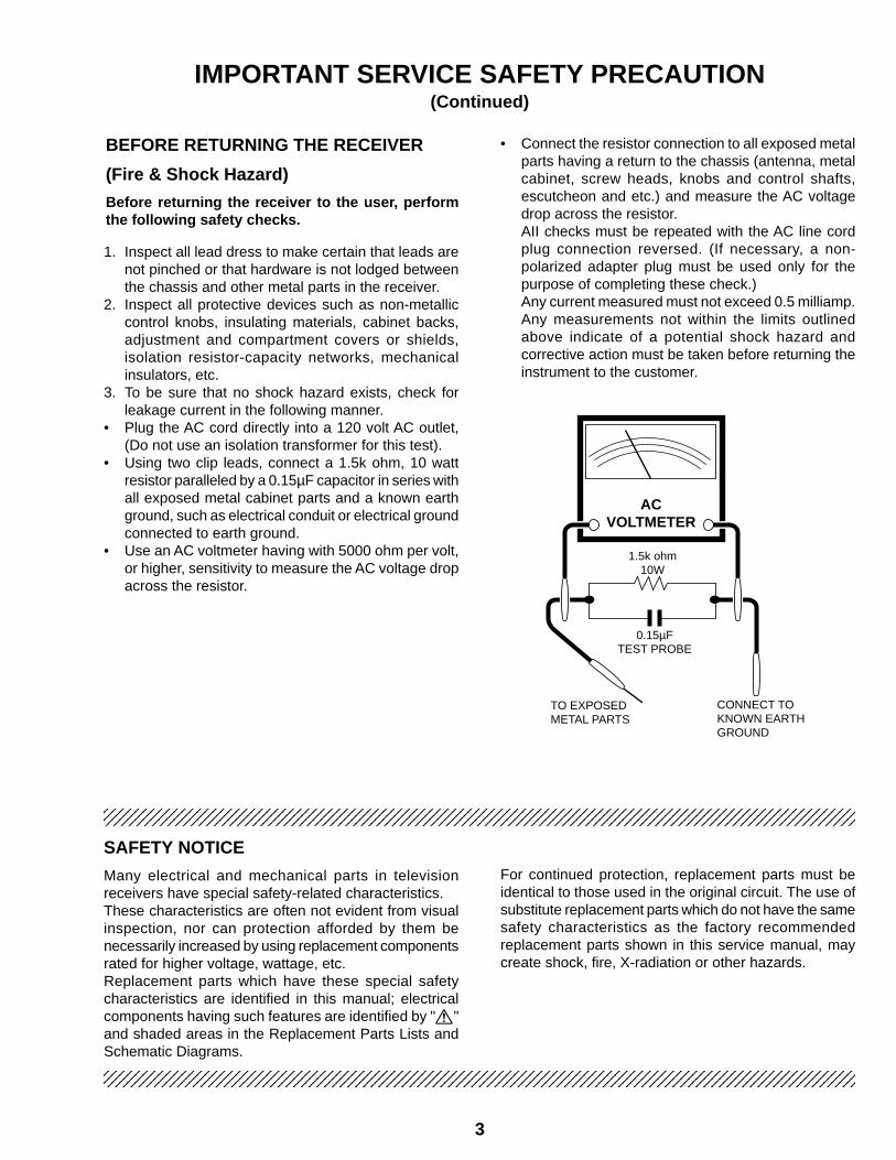
3. To be sure that no shock hazard exists, check forleakage current in the following manner.
• Plug the AC cord directly into a 120 volt AC outlet,(Do not use an isolation transformer for this test).
• Using two clip leads, connect a 1.5k ohm, 10 wattresistor paralleled by a 0.15µF capacitor in series withall exposed metal cabinet parts and a known earthground, such as electrical conduit or electrical groundconnected to earth ground.
• Use an AC voltmeter having with 5000 ohm per volt,or higher, sensitivity to measure the AC voltage dropacross the resistor.
For continued protection, replacement parts must beidentical to those used in the original circuit. The use ofsubstitute replacement parts which do not have the samesafety characteristics as the factory recommendedreplacement parts shown in this service manual, maycreate shock, fire, X-radiation or other hazards.
BEFORE RETURNING THE RECEIVER
(Fire & Shock Hazard)
Before returning the receiver to the user, performthe following safety checks.
• Connect the resistor connection to all exposed metalparts having a return to the chassis (antenna, metalcabinet, screw heads, knobs and control shafts,escutcheon and etc.) and measure the AC voltagedrop across the resistor.AII checks must be repeated with the AC line cordplug connection reversed. (If necessary, a non-polarized adapter plug must be used only for thepurpose of completing these check.)Any current measured must not exceed 0.5 milliamp.Any measurements not within the limits outlinedabove indicate of a potential shock hazard andcorrective action must be taken before returning theinstrument to the customer.
1.5k ohm10W
0.15µFTEST PROBE
CONNECT TOKNOWN EARTHGROUND
TO EXPOSEDMETAL PARTS
ACVOLTMETER

4
PRECAUTIONS A PRENDRE LORS DE LA REPARATIONNe peut effectuer la réparation qu' un technicien spécialisé qui s'est parfaitementaccoutumé à toute vérification de sécurité et aux conseils suivants.
AVERTISSEMENT
1. N'entreprendre aucune modification de tout circuit.C'est dangereux.
2. Débrancher le récepteur avant toute réparation.3. Les déversoirs thermiques à semi-conducteurs
peuvent présenter un danger de choc électriquelorsque le réceqteur est en marche.
4. Le châssis de ce récepteur possède deux systèmesde masse qui sont séparées par du matérield'isolation. Le système de masse non-isolée (soustension) est pour le circuit du régulateur de tensionB+ et le circuit de sortie horizontale. Le système demasse isolée est pour les tensions DC B+ basses etle circuit secondaire du transformateur haute tension.Pour éviter tout risque d'électrocution lors del'entretien de ce châssis, utiliser un transformateurd'isolation entre le cordon de ligne et la prise decourant.
4A 125V
PRECAUTION: POUR LAPROTECTION CONTINUECONTRE LES RISQUESD'INCENDIE, REMPLACER LEFUSIBLE PAR UN FUSIBLE DEMEME TYPE 4A-125V.
REPARATION DU SYSTEME A HAUTE TEN-SION ET DU TUBE-IMAGE
Lors de la réparation de ce systéme,supprimer la charge statique en branchantune résistance de 10 kΩ en série avec un filisolé (comme une sonde d'essai) entre lamise à la terre du tube-image et le fild'anodel. (Le corden d'alimentation doit êtreretiré de la prise murale.)
1. Le tube image dans ce récepteur emploie uneprotection intégrée contre l'implosion.
2. Par mesure de sécurité, changer le tube-image pourun tube du même numéro de type.
3. Ne pas lever le tube-image par son col.4. Ne manipuler le tube-image qu'en porant des lunettes
incassables et qu'après avoir déchargé totalementla haute tension.
LIMITES DES RADIATIONS X ET DE LAHAUTE TENSION
1. Tout le personnel réparateur doit être instruit desinstructions et procédés relatifs aux radiations X.Le tube-image, seule source de rayons X dons lestéleviseurs transistorisés, n'émet pourtant pas derayons mesurables si la haute tension est maintenueà un niveau préconisé dans la section "Vérificationde la haute tension".C'est seulement quand la haute tension est excessiveque les rayons X peuvent entrer dans l'enveloppe dutube-image y compris le conducteur de verre. Il estimportant de maintenir la haute tension en-dessousdu niveau spécifié.
2. Il est essentiel que le réparateur ait sous la main unvoltmètre à haute tension qui doit être périodiquementétalonné.
3. La haute tension doit toujours être maintenue à lavaleur de régime -et pas plus haute. L'opération àdes tensions plus élevées peut entraîner une pannedu tube-image ou du circuit à haute tension et, danscertaines conditions, peut entraîner une radiationdépassant les niveaux préscrits.
4. Quand le régulateur à haute tension fonctionnecorrectement, il n'y a aucun problème de radiationX. Chaque fois qu'un châssis couleurs est réparé, laluminosité doit être examinée bout en contrôlant lahaute tension à l'aide d'un voltmètre pour s'assurerque la haute tension ne dépasse pas la valeurspécifiée et qu'elle soit correctement réglée.
5. Ne pas utiliser un tube-image autre que celui spécifiéet ne pas effectuer de modifications déconseilléesdu circuit à haute tension.
6. Lors de la recherche des pannes et des mesuresd'essai sur un récepteur qui présente une hautetension excessive, éviter de s'approcher inutilementdu récepteur.Ne pas faire fonctionner le récepteur plus longtempsque nécessaire pour localiser la cause de la tensionexcessive.

5
VERIFICATIONS CONTRE L'INCEN-DIE ETLE CHOC ELECTRIQUE
Avant de rendre le récepteur à l'utilisateur, effectuerles vérifications suivantes.
123456789012345678901234567890121234567890123456789012345678901212345678901234567890123456789012121234567890123456789012345678901212345678901234567890123456789012123456789012345678901234567890121212345678901234567890123456789012123456789012345678901234567890121234567890123456789012345678901212
123456789012345678901234567890121234567890123456789012345678901212345678901234567890123456789012121234567890123456789012345678901212345678901234567890123456789012123456789012345678901234567890121212345678901234567890123456789012123456789012345678901234567890121234567890123456789012345678901212
AVIS POUR LA SECURITE
De nombreuses pièces, électriques et mécaniques, dansles téléviseurs présentent des caractéristiques spécialesrelatives à la sécurité, qui ne sont souvent pas évidentesà vue. Le degré de protection ne peut pas êtrenécessairement augmentée en utilisant des pièces deremplacement étalonnées pour haute tension,puissance, etc.Les pièces de remplacement qui présentent cescaractéristiques sont identifiées dans ce manuel; lespièces électriques qui présentent ces particularités sont
PRECAUTIONS A PRENDRE LORS DE LA REPARATION(Suite)
1. Inspecter tous les faisceaux de câbles pour s'assurerque les fils ne soient pas pincés ou qu'un outil ne soitpas placé entre le châssis et les autres piècesmétalliques du récepteur.
2. Inspecter tous les dispositifs de protection commeles boutons de commande non-métalliques, lesisolants, le dos du coffret, les couvercles ou blindagesde réglage et de compartiment, les réseaux derésistance-capacité, les isolateurs mécaniques, etc.
3. S'assurer qu'il n'y ait pas de danger d'électrocutionen vérifiant la fuite de courant, de la facon suivante:
• Brancher le cordon d'alimentation directem-ent à uneprise de courant de 120V. (Ne pas utiliser detransformateur d'isolation pour cet essai).
• A l'aide de deux fils à pinces, brancher une résistancede 1,5 kΩ 10 watts en parallèle avec un condensateurde 0,15µF en série avec toutes les pièces métalliquesexposées du coffret et une terre connue comme uneconduite électrique ou une prise de terre branchée àla terre.
• Utiliser un voltmètre CA d'une sensibilité d'au moins5000Ω/V pour mesurer la chute de tension en traversde la résistance.
TO EXPOSEDMETAL PARTS
CONNECT TOKNOWN EARTHGROUND
• Toucher avec la sonde d'essai les pièces métalliquesexposées qui présentent une voie de retour auchâssis (antenne, coffret métallique, tête des vis,arbres de commande et des boutons, écusson, etc.)et mesurer la chute de tension CA en-travers de larésistance. Toutes les vérifications doivent êtrerefaites après avoir inversé la fiche du cordond'alimentation. (Si nécessaire, une prise d'adpatationnon polarisée peut être utilisée dans le but de terminerces vérifications.)Tous les courants mesurés ne doivent pas dépasser0,5 mA.Dans le cas contraire, il y a une possibilité de chocélectrique qui doit être supprimée avant de rendre lerécepteur au client.
identifiées par la marque " å " et hachurées dans laliste des pièces de remplacement et les diagrammesschématiques.Pour assurer la protection, ces pièces doivent êtreidentiques à celles utilisées dans le circuit d'origine.L'utilisation de pièces qui n'ont pas les mêmescaractéristiques que les pièces recommandées parl'usine, indiquées dans ce manuel, peut provoquer desélectrocutions, incendies, radiations X ou autresaccidents.
Voltmètre CA
1.5k ohm10W
BRANCHER A UNETERRE CONNUE
AUX PIECESMETALLIQUESEXPOSEES
0.15µFSONDE D'ESSAI
6
LOCATION OF USER'S CONTROL
TV/CATV
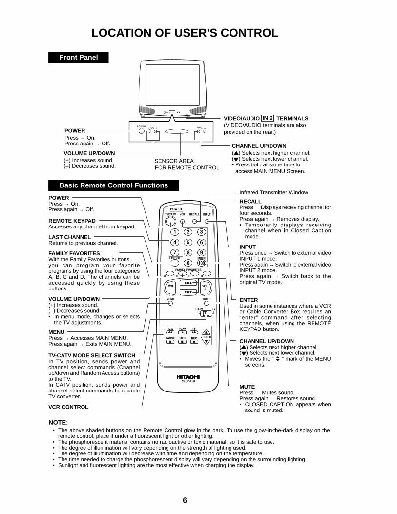
Front Panel
Basic Remote Control FunctionsInfrared Transmitter Window
RECALLPress → Displays receiving channel forfour seconds.Press again → Removes display.• Temporarily displays receiving
channel when in Closed Captionmode.
INPUTPress once → Switch to external videoINPUT 1 mode.Press again Switch to external videoINPUT 2 mode.Press again →
→
Switch back to theoriginal TV mode.
ENTERUsed in some instances where a VCRor Cable Converter Box requires an“enter” command after selectingchannels, when using the REMOTEKEYPAD button.
CHANNEL UP/DOWN(') Selects next higher channel.(") Selects next lower channel.• Moves the “ ” mark of the MENU
screens.
MUTEPress Mutes sound.Press again Restores sound.• CLOSED CAPTION appears when
sound is muted.
• The above shaded buttons on the Remote Control glow in the dark. To use the glow-in-the-dark display on theremote control, place it under a fluorescent light or other lighting.
• The phosphorescent material contains no radioactive or toxic material, so it is safe to use.• The degree of illumination will vary depending on the strength of lighting used.• The degree of illumination will decrease with time and depending on the temperature.• The time needed to charge the phosphorescent display will vary depending on the surrounding lighting.• Sunlight and fluorescent lighting are the most effective when charging the display.
NOTE:
POWERPress → On.Press again → Off.
REMOTE KEYPADAccesses any channel from keypad.
LAST CHANNELReturns to previous channel.
FAMILY FAVORITESWith the Family Favorites buttons,you can program your favoriteprograms by using the four categoriesA, B, C and D. The channels can beaccessed quickly by using thesebuttons.
VOLUME UP/DOWN(+) Increases sound.(–) Decreases sound.• In menu mode, changes or selects
the TV adjustments.
MENUPress → Accesses MAIN MENU.Press again → Exits MAIN MENU.
TV-CATV MODE SELECT SWITCHIn TV position, sends power andchannel select commands (Channelup/down and Random Access buttons)to the TV.In CATV position, sends power andchannel select commands to a cableTV converter.
VCR CONTROL
– +POWER
POWERPress → On.Press again → Off.
VOLUME UP/DOWN(+) Increases sound.(–) Decreases sound.
SENSOR AREA FOR REMOTE CONTROL
CHANNEL UP/DOWN( ) Selects next higher channel.( ) Selects next lower channel.• Press both at same time to access MAIN MENU Screen.
VIDEO/AUDIO TERMINALS(VIDEO/AUDIO terminals are alsoprovided on the rear.)
IN 2
'
"
VIDEO IN L-AUDIO-R
VOL

7
CIRCUIT PROTECTION
The receiver is protected by a 4.0A fuse (F701),mounted on PWB-A, wired into one side of the ACline input.
X-RADIATION PROTECTOR CIRCUIT TEST
After service has been performed on the horizontaldeflection system, high voltage system, B+ system,test the X-Radiation protection circuit to ascertainproper operation as follows:
1. Apply 120V AC using a variac transformer foraccurate input voltage.
2. Allow for warm up and adjust all customer controlsfor normal picture and sound.
3. Receive a good local channel.4. Connect a digital voltmeter to TP653 and make sure
that the voltmeter reads 11.2 ± 0.6V.5. Apply external 13.8V DC at TP653 by using an
external DC supply, TV must shut off.6. To reset the protector, unplug the AC cord and make
a short circuit between TP651 and TP652. Now makesure that normal picture appears on the screen.
7. If the operation of the horizontal oscillator does notstop in step 5, the circuit must be repaired before theset is returned to the customer.
HIGH VOLTAGE CHECK
High voltage is not adjustable but must be checkedto verify that the receiver is operating within safeand efficient design limitations as specified. Checksshould be as follows:
1. Connect an accurate high voltage meter betweenground and anode of picture tube.
2. Operate receiver for at least 15 minutes at 120V ACline voltage, with a strong air signal or a properly tunedin test signal.
3. Enter the service mode and select the serviceadjustment "S19" and Bus data "01" (Y-mute on).
4. The voltage should be approximately, 28.7kV (at zerobeam).If a correct reading cannot be obtained, check circuitryfor malfunctioning components. After the voltage test,make Y-mute off to the normal mode.
INSTALLATION AND SERVICE INSTRUCTIONSNote: (1) When performing any adjustments to resistor controls and transformers use non-metallic
screwdrivers or TV alignment tools.(2) Before performing adjustments, the TV set must be on at least 15 minutes.
8
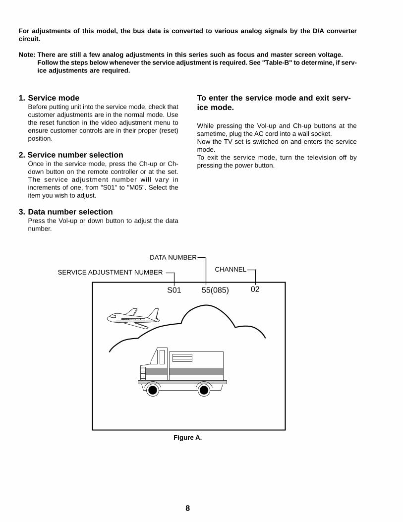
Figure A.
S01 02
CHANNELSERVICE ADJUSTMENT NUMBER
DATA NUMBER
S01 D:00
For adjustments of this model, the bus data is converted to various analog signals by the D/A convertercircuit.
Note: There are still a few analog adjustments in this series such as focus and master screen voltage.Follow the steps below whenever the service adjustment is required. See "Table-B" to determine, if serv-ice adjustments are required.
1. Service modeBefore putting unit into the service mode, check thatcustomer adjustments are in the normal mode. Usethe reset function in the video adjustment menu toensure customer controls are in their proper (reset)position.
2. Service number selectionOnce in the service mode, press the Ch-up or Ch-down button on the remote controller or at the set.The service adjustment number will vary inincrements of one, from "S01" to "M05". Select theitem you wish to adjust.
3. Data number selectionPress the Vol-up or down button to adjust the datanumber.
To enter the service mode and exit serv-ice mode.
While pressing the Vol-up and Ch-up buttons at thesametime, plug the AC cord into a wall socket.Now the TV set is switched on and enters the servicemode.To exit the service mode, turn the television off bypressing the power button.
55(085)

9
SERVICE NUMBER
DATAADJUSTMENT CONTENTSADJUSTMENT ITEM
RANGEINITIAL VALUE
S01 PICTURE 55 00-7FS02 TINT 46 00-7FS03 COLOR 32 00-7FS04 BRIGHTNESS 40 00-7FS05 SHARPNESS 28 00-3F Must be set to "28"S06 VERTICAL PHASE 00 00-07 Must be set to "00"S07 HORIZONTAL PHASE 12 00-1FS08 RF-AGC 23 00-3FS09 VERTICAL AMP 20 00-3FS10 PIF VCO 2C 00-7FS11 R CUT-OFF 00 00-FFS12 G CUT -OFF 00 00-FFS13 B CUT-OFF 00 00-FFS14 G GAIN 7F 00-FFS15 B GAIN 7F 00-FFS16 TRAP 00 00 or 01 Must be set to "00"S17 BALANCE 20 00-3F Must be set to "20"S18 C.C.POSITION 17 00-7FS19 MUTE 00 00,01,03 "00"=Normal, "01"=No-Y, "03"=No VerticalS20 ENERGY SAVE OFFSET 20 00-3F Must be set to "23"S21 D.D.E. OFFSET 03 00-1F Must be set to "03"S22 OSD SETUP 00 00-03 Must be set to "00"S23 TUNER SETUP 00 00, 01 Must be set to "00"OP1 OPTION1 (Set to each mode) 00 00-FF "B3"OP2 OPTION2 00 00-FF "A7"M01 INPUT LEVEL 0A 00-0FM02 ST VCO 20 00-3FM03 FILTER 1C 00-3FM04 WIDE BAND 20 00-3FM05 SPECTRAL 1B 00-3F
NECESSARY UNNECESSARY
ADJUSTMENTNOTESPART REPLACED
IC2001
IC2101 X
IC3001 X
CRT X
IC201 X
X Data is stored in IC2101.
The adjustment is needed to compensate for characteristicsof parts including IC201 and MTS level (M01).
Holding down both the Vol-up/CH-down buttons on the TVset in the service mode for more than 2 seconds willautomatically write the above initial values into IC2101. Thenperform a complete adjustment.
Adjust items related to picture tube only.
Adjust items related to MTS only (M01~M05).
Holding down both the Vol-up/CH-down buttons on the TV set at service mode for more than 2 seconds willautomatically write the above initial values into IC2101.
Table - A
Table - B

10
SERVICE ADJUSTMENTVCO Adjustment
1. Connect a digital voltmeter between pin (44) of IC201and ground.
2. Receive a good local channel.3. Enter the service mode and select the service
adjustment "S10".4. Adjust the data so that digital voltmeter reads 2.2V.5. Adjustment is completed, remove the voltmeter,
return to "normal" mode.
RF AGC Adjustment
1. Receive a good local channel.2. Enter the service mode and select the service
adjustment "S08".3. Set the data value to point where no noise or beat
appears.4. Select another channel to confirm that no noise or
beat appears.Note 1 : You will have to come out of the service
mode to select another channel.Note 2 : Setting the data to "00" will produce a black
raster.
Screen Adjustment
1. Connect a oscilloscope between TP854 and GNDon the CRT Unit.
2. Receive a good local channel.3. Enter the service mode and select the service
adjustment "S03" and set the data value to "00" toset the color level to minimum. (Record original datacode under adjustment "S03" before changing) Youmay skip this step, if you selected a B/W picture ormonoscope pattern.
4. Select the service adjustment "S19" and adjust thedata value to "01", this turn off the luminance signal(Y-mute).
5. Select the service adjustment "S04" and adjust datavalue to obtain 2.35 volts on the oscilloscope screen.
6. Adjust the master screen control until the rasterdarkens to the point where raster is barely seen.
7. Adjust the service adjustments "S11" red, "S12" greenand "S13" blue to obtain a good grey scale withnormal whites at low brightness level.
8. Select the service adjustment "S19" and reset datato "00". Select the service adjustment "S03" and resetdata to obtain normal color level.
9. Remove oscilloscope, and reset the master screencontrol to obtain normal brightness range.
White Balance Adjustment
1. Receive a good local channel.2. Enter the service mode and select the service
adjustment "S03" and set to "00" (minimumcolor)(Record original data code under adjustment"S03" before changing). "S03" does not have to beadjusted, if you selected a B/W picture or monoscopepattern.
3. Alternately adjust the service adjustment data of "S14"and "S15" until a good grey scale with normal whitesis obtained.
4. Select the service adjustment "S03" and adjust datato obtain normal color level.
Sub-Picture Adjustment
1. Receive a good local channel.2. Make sure the customer picture control is set to
maximum.3. Enter the service mode and select the service
adjustment "S01".4. Adjust the data value to achieve normal contrast
range.
Sub-Tint Adjustment
1. Receive a good local channel.2. Set customer tint control to center of it's range.3. Enter the service mode and select the service
adjustment "S02".4. Adjust "S02" data value to obtain normal flesh tones.
Sub-Color Adjustment
1. Receive a good local channel.2. Make sure the customer color control is set to center
position .3. Enter the service mode and select service adjustment
"S03".4. Adjust "S03" data value to obtain normal color level.
11
3.58MHz Trap Adjustment
1. Receive a good local channel.2. Enter the service mode and select the service
adjustment "S16".3. This is a two position adjustment, "00" is ON, "01" is
OFF.4. Models should be adjusted as follows.
Sharpness and Audio Balance Adjust-ments
1. Receive a good local channel.2. Enter the service mode and select the service
adjustments "S05" for sharpness and "S17" forbalance.
» Sharpness Adjustment3. Adjust data value to "28"(center of data range) for
sharpness adjustment.» Audio Balance Adjustment4. Adjust data value to "20"(center of data range) for
audio balance adjustment.
Energy save offset Adjustment
1. Enter the service mode and select the serviceadjustment "S20".
2. Adjust data value to "23".Note : This position is used to preset the level for the
energy save function.
Other Adjustments
1. Enter the service mode.2. Adjust the following data values as listed below.
Sub-Brightness Adjustment
1. Receive a good local channel.2. Make sure the customer brightness control is set to
center position.3. Enter the service mode and select the service
adjustment "S04".4. Adjust "S04" data value to obtain normal brightness
level.
Vertical-Size Adjustment
1. Receive a good local channel.2. Enter the service mode and select the service
adjustment "S09".3. While observing the top and bottom of the screen,
adjust "S09" data value to proper vertical size.
Vertical Phase Adjustment
1. Enter the service mode and select the serviceadjustment "S06".
2. Adjust data value to "00".Note: This must be set "00" when changed data retrace
line will appear.
Horizontal Position Adjustment
1. Receive a good local channel.2. Enter the service mode and select the service
adjustment "S07".3. Adjust "S07" data value so that picture is centered.
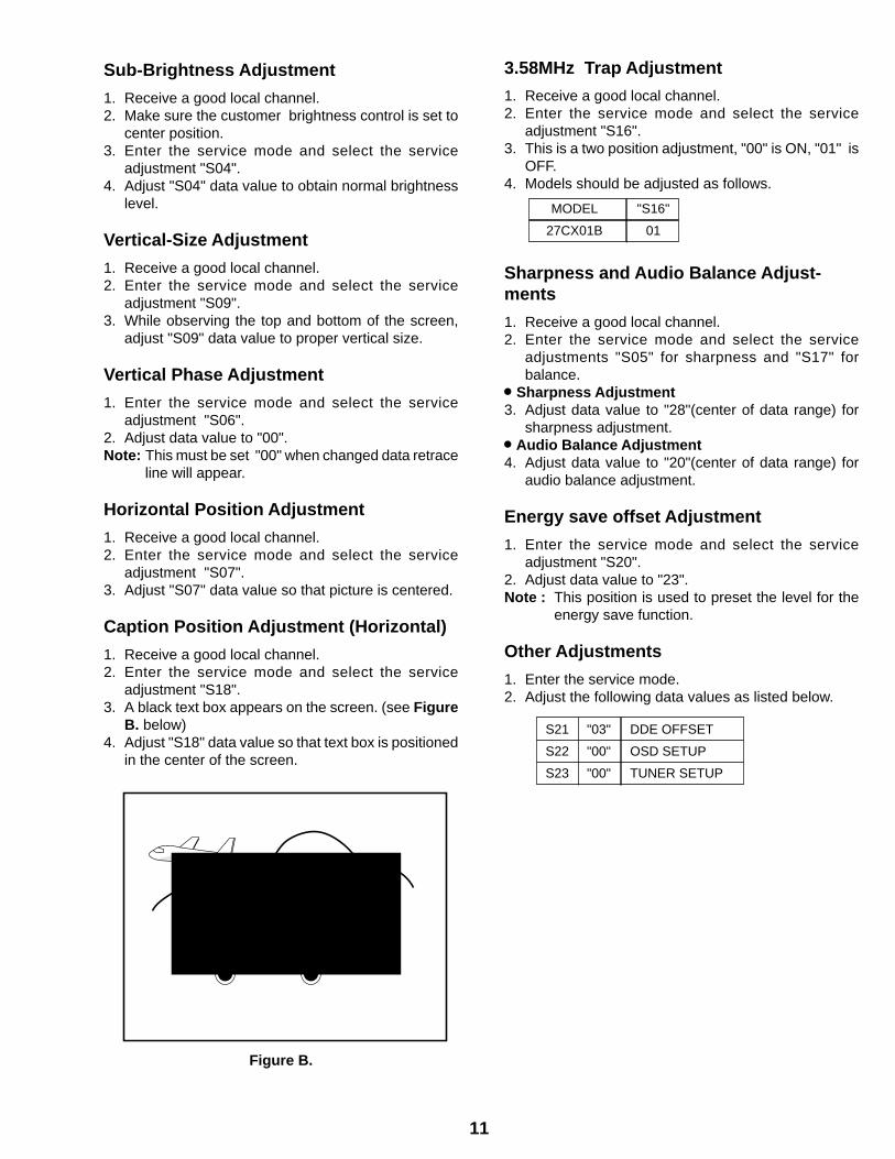
Caption Position Adjustment (Horizontal)
1. Receive a good local channel.2. Enter the service mode and select the service
adjustment "S18".3. A black text box appears on the screen. (see Figure
B. below)4. Adjust "S18" data value so that text box is positioned
in the center of the screen.
MODEL "S16"
27CX01B 01
Figure B.
S21 "03" DDE OFFSET
S22 "00" OSD SETUP
S23 "00" TUNER SETUP

12
MTS ADJUSTMENT
MTS Level Adjustment1. Feed the following monaural signal to pin (14) of
IC3001.Monaural signal : 300Hz, 245mVrms
2. Connect the rms voltmeter to pin (39) of IC3001.3. Enter the service mode and select the service
adjustment "M01".4. Adjust the data so that the rms voltmeter reads.
Spec.: 490 ±10mVrms.
MTS VCO Adjustment1. Keep the unit in no-signal state.2. Connect the frequency counter to pin (39) of IC3001.3. Connect a capacitor (100µF, 50V) in between
positive(+) side of C3005 and ground.4. Enter the service mode and select the service
adjustment "M02"5. Adjust the data so that the frequency counter reads.
Spec.: 62.94 ±0.75kHz.
Filter Adjustment1. Feed the following stereo pilot signal to pin (14) of
IC3001 .Stereo pilot signal: 9.4kHz, 600mVrms.
2. Enter the service mode and select the serviceadjustment "M03".
3. Adjust the data at the point where "OK" appears onthe screen. The "OK" represents the approximatecenter of the adjustable range of the data.
Separation Adjustment1. Connect the rms voltmeter to pin (39) of IC3001.2. Receive the following composite stereo signal 1.
Composite stereo signal: 30% modulation, leftchannel only, noise reduction on, 300Hz
3. Enter the service mode and select the serviceadjustment "M04".
4. Adjust the data until the AC voltage reading of therms voltmeter is minimum.
5. Receive the following composite stereo signal 2.Stereo signal: 30% modulation, left channel only,noise reduction on, 3kHz
6. Enter the service mode and select the serviceadjustment "M05".
7. Adjust the data until the AC voltage reading of therms voltmeter is minimum.
8. Take the above steps 1 thru 8 again for fineadjustment.

13
1716 1918151413121110
CHASSIS LAYOUT
654321
A
B
C
D
E
F
G
H
PWB-K
PWB-B
PWB-H
PWB-A
14
87 109654321
A
B
C
D
E
F
G
H
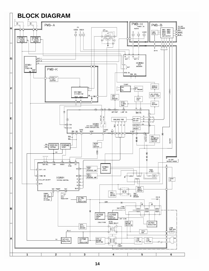
BLOCK DIAGRAM
654321
A
B
C
D
E
F
G
H
15
1716 1918151413121110
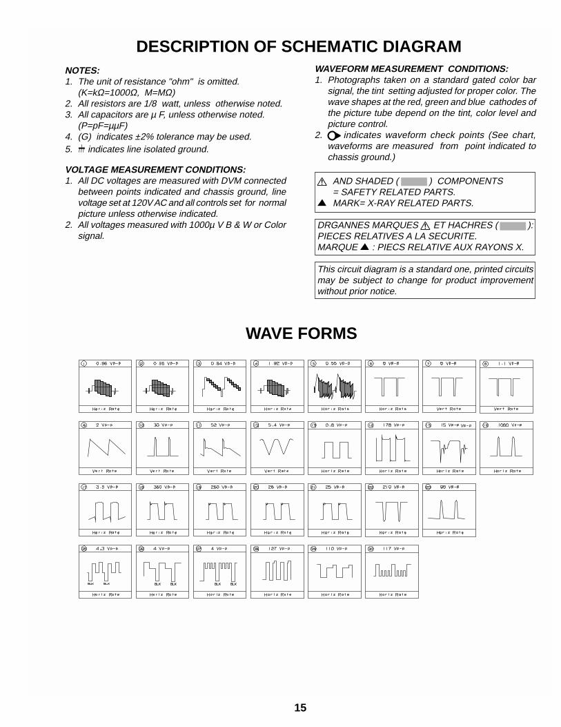
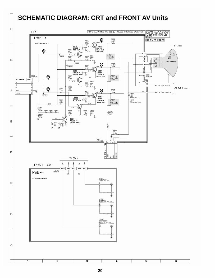
DESCRIPTION OF SCHEMATIC DIAGRAMNOTES:1. The unit of resistance "ohm" is omitted.
(K=kΩ=1000Ω, M=MΩ)2. All resistors are 1/8 watt, unless otherwise noted.3. All capacitors are µ F, unless otherwise noted.
(P=pF=µµF)4. (G) indicates ±2% tolerance may be used.5. indicates line isolated ground.
VOLTAGE MEASUREMENT CONDITIONS:1. All DC voltages are measured with DVM connected
between points indicated and chassis ground, linevoltage set at 120V AC and all controls set for normalpicture unless otherwise indicated.
2. All voltages measured with 1000µ V B & W or Colorsignal.
WAVEFORM MEASUREMENT CONDITIONS:1. Photographs taken on a standard gated color bar
signal, the tint setting adjusted for proper color. Thewave shapes at the red, green and blue cathodes ofthe picture tube depend on the tint, color level andpicture control.
2. indicates waveform check points (See chart,waveforms are measured from point indicated tochassis ground.)
å AND SHADED ( ) COMPONENTS= SAFETY RELATED PARTS.
' MARK= X-RAY RELATED PARTS.
DRGANNES MARQUES å ET HACHRES ( ):PIECES RELATIVES A LA SECURITE.MARQUE ' : PIECS RELATIVE AUX RAYONS X.
This circuit diagram is a standard one, printed circuitsmay be subject to change for product improvementwithout prior notice.
WAVE FORMS
1716
121110987654321
A
B
C
D
E
F
G
H
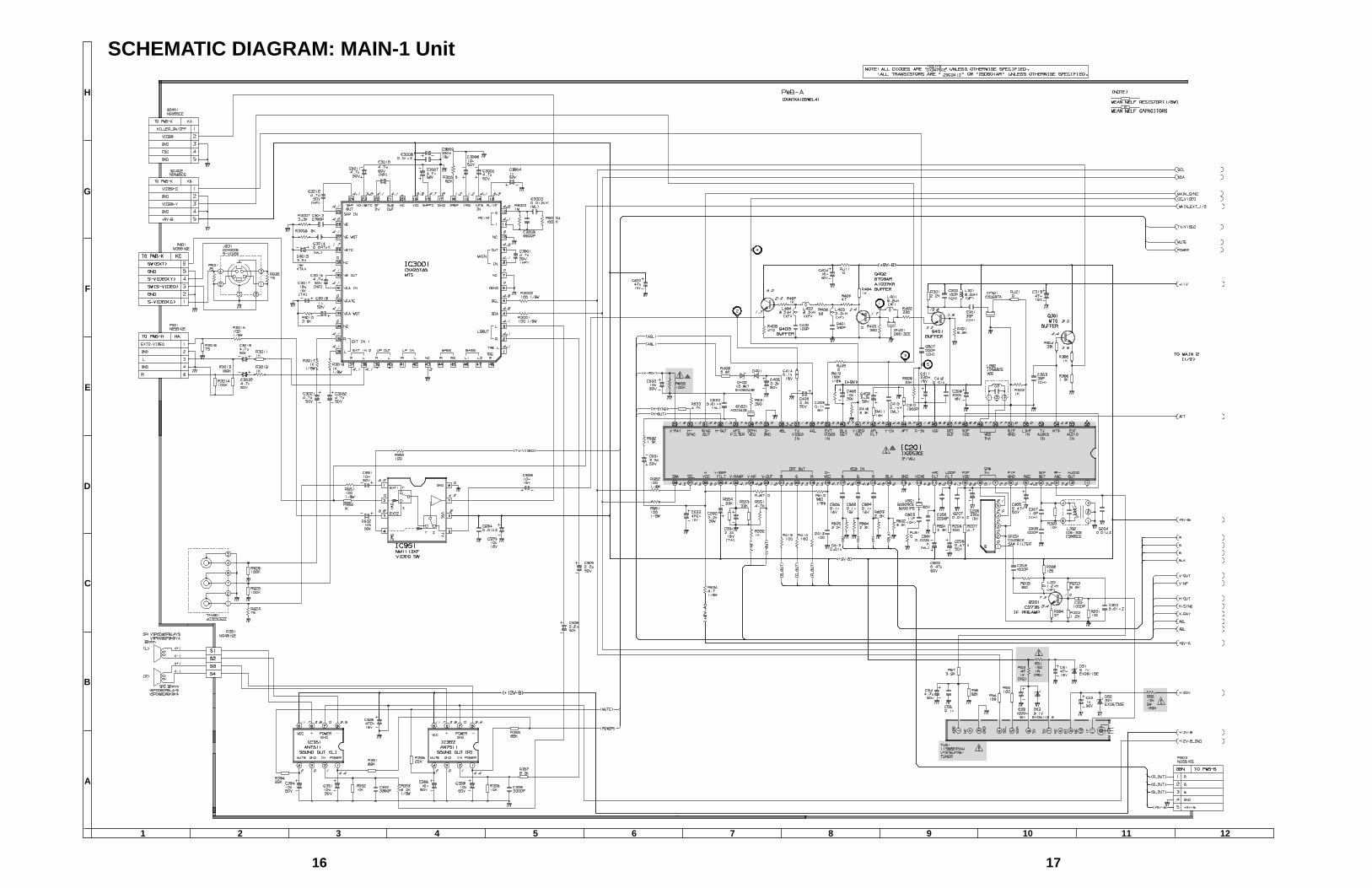
SCHEMATIC DIAGRAM: MAIN-1 Unit
1918
121110987654321
A
B
C
D
E
F
G
H
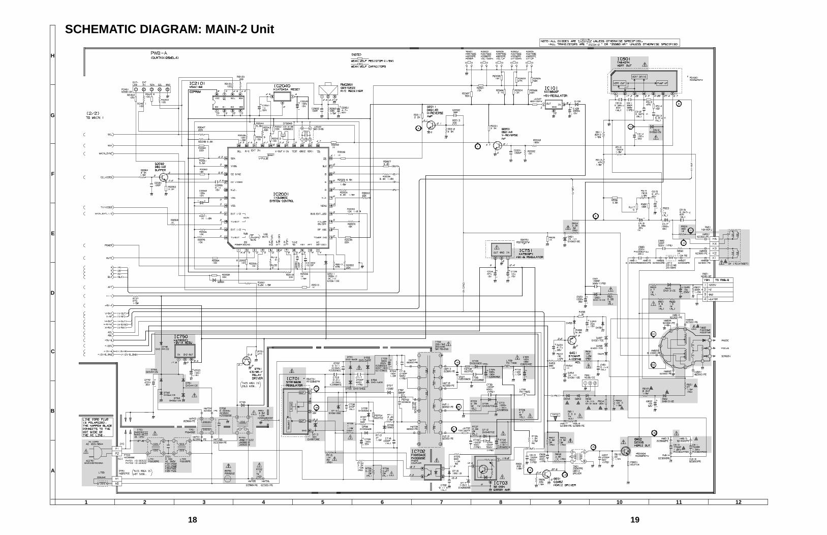
SCHEMATIC DIAGRAM: MAIN-2 Unit
20
87 109654321
A
B
C
D
E
F
G
H
654321
A
B
C
D
E
F
G
H
SCHEMATIC DIAGRAM: CRT and FRONT AV Units

21
654321
A
B
C
D
E
F
G
H
SCHEMATIC DIAGRAM: S-VIDEO Unit
22
654321
A
B
C
D
E
F
G
H
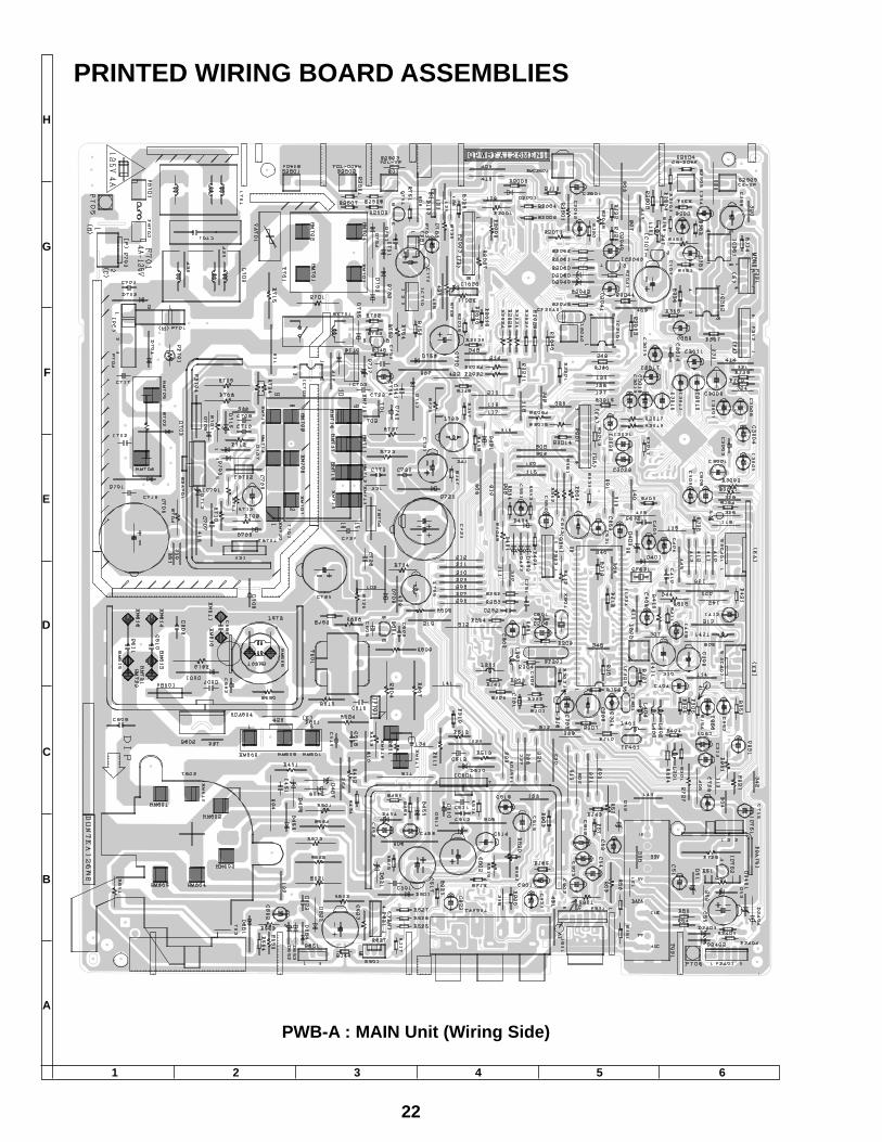
PWB-A : MAIN Unit (Wiring Side)
PRINTED WIRING BOARD ASSEMBLIES
23
654321
A
B
C
D
E
F
G
H
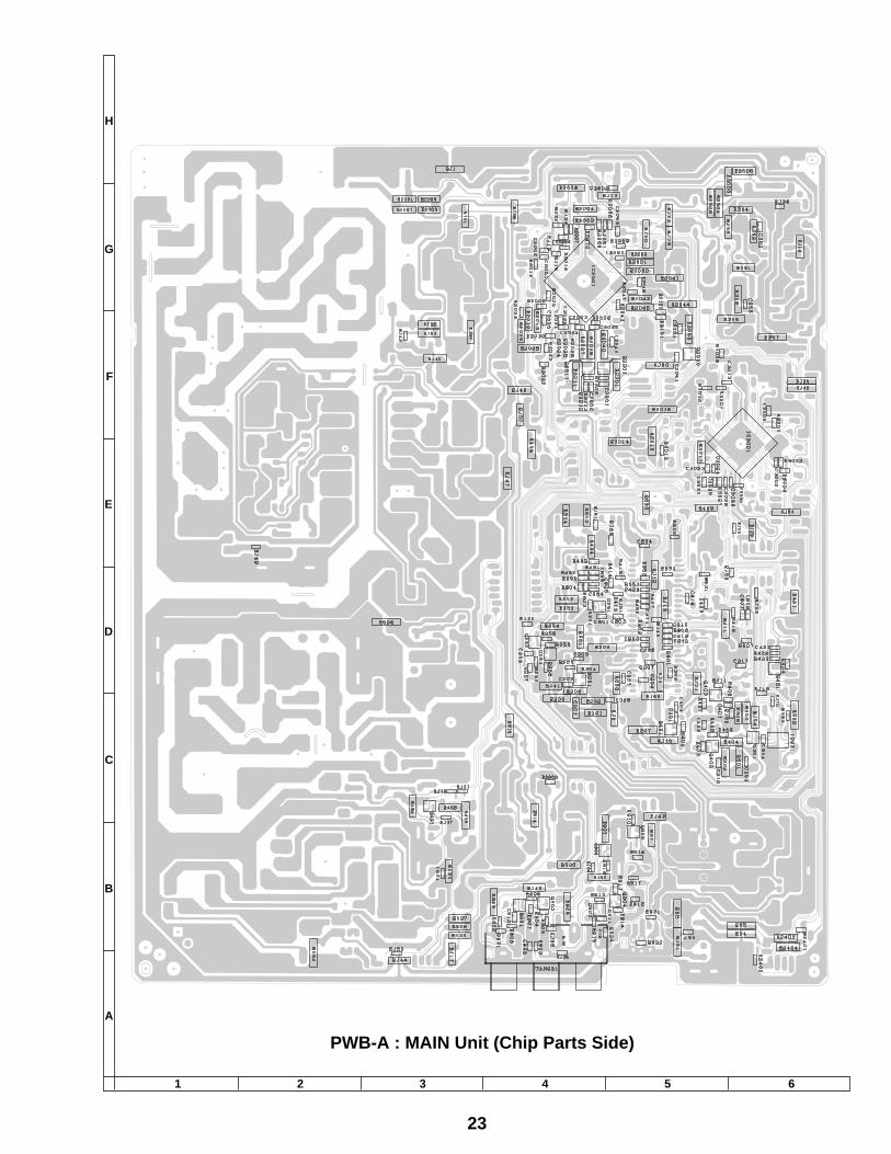
PWB-A : MAIN Unit (Chip Parts Side)

24
654321
A
B
C
D
E
F
G
H
PWB-B : CRT Unit (Wiring Side)
PWB-H : FRONT AV Unit (Wiring Side)
Q1
50
4
Q 1 5 0 3
R 1 5 0 1
R 1 5 1 0R 1 5 0 9
C 1 5 0 6C 1 5 0 5C 1 5 0 4
R 1 5 0 5C 1 5 0 2R 1 5 0 6R 1 5 0 3
R1
50
2
Q1
50
1Q
15
02
R1
50
4
R 1 5 0 8R 1 5 0 7
R1
51
1
L1
50
2
L 1 5 0 1
L 1 5 0 3C 1 5 0 7
R 1 5 1 3R 1 5 1 2
J 3
J 6
I C 1 5 0 1
P 1 5 0 3 K C
R 1 5 1 7 R 1 5 1 5
C 1 5 1 3 D 1 5 0 4
J 2
J 1
1 6D 1 5 0 1
C1
50
1R
15
18
J5
J4
C1
51
1
C1
50
8
C1
50
3
R1
51
6
R1
51
9
D1
50
2
C1
50
9
C1
51
2K
B1
D1
50
3C
15
10
R1
51
4
P1
50
2
5
KA
1
5
P1
50
1
PWB-K : S-VIDEO Unit (Wiring Side)
Ref. No. Part No. Description Ref. No. Part No. Description
25
Ref. No. Part No. Description
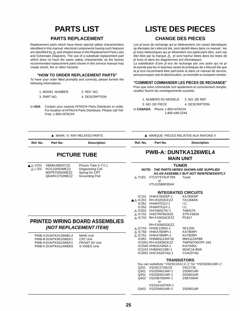
PICTURE TUBE
PWB-A DUNTKA126WEL4 MAIN UnitPWB-B DUNTK9510WEK1 CRT UnitPWB-H DUNTK9310WEK1 FRONT AV UnitPWB-K DUNTKA114WEK0 S-VIDEO Unit
PRINTED WIRING BOARD ASSEMBLIES(NOT REPLACEMENT ITEM)
Ref. No. Part No. Description
çå V101 VB68AJB82071E Picture Tube (I.T.C.)å L703 RCiLG0054MEZZ Degaussing Coil
MSPRT0002MEZZ Spring for CRTQEARC2702MEZZ Grounding Part
TUNERNOTE: THE PARTS HERES SHOWN ARE SUPPLIED
AS AN ASSEMBLY BUT NOT INDEPENEDENTLY.å TU51 VTUVTST5UF78S Tuner
orVTU115B8035AH
INTEGRATED CIRCUITSIC101 VHiKA78S05P-1 KA78S05P
çå IC201 RH-iX3253CEZZ TA1268ANIC351 VHiAN7511//-1 I.C.IC352 VHiAN7511//-1 I.C.
å IC501 VHiTA8427K/-1 TA8427Kå IC701 VHiSTRF66261E STR-F6626å IC702 RH-FX0034CEZZ PC817
orRH-FX0002GEZZ
å IC703 VHiSE120N//-1 SE120Nå IC750 VHiKA7809Pi-1 KA7809PIå IC751 VHiKA7809Pi-1 KA7809PI
IC951 VHiMM1113XF1E MM1113XFBEIC2001 RH-iX3436CEZZ TMPA8700CPF-164IC2040 VHiKiA7045A-1 KIA7045AIC2101 VHiM24C16B/-1 M24C16-BN6IC3001 VHiCXA2074Q-1 CXA2074Q
TRANSISTORSYou can substitute "VS2SC2412-C-1" for "VS2SD601AR/-1".Q201 VS2SC2735//1E 2SC2735Q301 VS2SD601AR/-1 2SD601ARQ401 VS2SD601AR/-1 2SD601ARQ402 VS2SB709AR/-1 2SB709AR
orVS2SA1037KR-1
Q403 VS2SD601AR/-1 2SD601AR
PARTS LISTPARTS REPLACEMENT
Replacement parts which have these special safety characteristicsidentified in this manual; electrical components having such featuresare identified by å and shaded areas in the Replacement Parts Listsand Schematic Diagrams. The use of a substitute replacement partwhich dose no have the same safety characteristic as the factoryrecommended replacement parts shown in this service manual maycreate shock, fire or other hazards.
"HOW TO ORDER REPLACEMENT PARTS"To have your order filled promptly and correctly, please furnish thefollowing informations.
1. MODEL NUMBER 2. REF. NO.
3. PART NO. 4. DESCRIPTION
in USA: Contact your nearest HITACHI Parts Distributor to order.For location of HITACHI Parts Distributor, Please call Toll-Free; 1-800-HITACHI
MARK: SPARE PARTS-DELIVERY SECTION
MARK: X- RAY RELATED PARTS
LISTE DES PIECESCHANGE DES PIECES
Les pi`eces de rechange qui pr élelesentent ces caract éleristiquessp éleciales de s élecurit éle, sont identifi élees dans ce manuel : lespi`eces élelectriques qui pr élesentent ces particularit éles, sont repéler élee par la marque å et sont hachur élees dans les listes depi`eces et dans les diagrammes sch élematiques.La substitution d'une pi`ece de rechange par une autre qui ne préLesente pas les m éoemes caract éLeristiques de s élecurit éle quela pi`ece recommand élee parl'usine et dans ce manuel de service,peut provoquer une éLelectrocution, un incendie ou toutautre sinistre.
"COMMENT COMMANDER LES PIECES DE RECHANGE"Pour que votre commande soit rapidement et correctement remplie,veuillez fournir les renseignements suivants.
1. NUMERO DU MODELE 2. NO. DE REF
3. NO. DE PIECE 4. DESCRIPTION
in CANADA: Phone 1-800-HITACHI1-800-448-2244
MARQUE: SECTION LIVRAISON DES PIECES DE RECHANGE
MARQUE: PIECES RELATIVE AUX RAYONS X
PWB-A: DUNTKA126WEL4MAIN UNIT
Ref. No. Part No. Description Ref. No. Part No. Description
26
COILSL201 VP-XF1R2K0000 Peaking 1.2µHL202 RCiLi0588CEZZ VCO CoilL301 VP-XF8R2K0000 Peaking 8.2µHL302 RCiLi0613CEZZ IF Coil
orRCiLi0605CEZZ
L401 VP-XF6R8K0000 Peaking 6.8µHL402 VP-XF3R3K0000 Peaking 3.3µHL403 VP-XF8R2K0000 Peaking 8.2µHL404 VP-XF8R2K0000 Peaking 8.2µHL672 RCiLZ0101MEZZ Coil
orRCiLZ0102MEZZ
å L701 RCiLF0025PEZZ Coilå L702 RCiLF0025PEZZ Coilå L705 RCiLP0179CEZZ Coil
L729 RCiLP0179CEZZ CoilL2040 RCiLB0131CEZZ Oscillation Coil
TRANSFORMERST601 RTRNZ0057PEZZ Transformer
çå T602 RTRNF0033MEZZ H-Volt Transformer orRTRNF0037MEZZ
å T701 RTRNP0543CEZZ Power Transformerå T702 RTRNZ0017MEZZ Transformer
orRTRNZ0022MEZZ
CAPACITORS[EL.··· Electrolytic, M-Poly.··· Metalized Polypro Film]
C51 VCEA0A1CW476M 47 16V EL.C53 VCEA0A1HW105M 1 50V EL.C54 VCEA0A1HW475M 4.7 50V EL.C55 VCEA0A1CW108M 1000 16V EL.C56 VCKYCY1CB104K 0.1 16V CeramicC103 VCEA0A1CW228M 2200 16V EL.C201 VCKYMN1HB102K 1000p 50V CeramicC202 VCKYCY1HF103Z 0.01 50V CeramicC203 VCKYCY1HB102K 1000p 50V CeramicC204 VCKYCY1HF103Z 0.01 50V CeramicC205 VCEA0A1HW474M 0.47 50V EL.C206 VCEA0A1CW337M 330 16V EL.C207 VCKYCY1HF103Z 0.01 50V CeramicC208 VCEA0A1HW474M 0.47 50V EL.C209 VCKYCY1HB222K 2200p 50V CeramicC210 VCKYCY1HB102K 1000p 50V CeramicC301 VCCCCY1HH330J 33p 50V CeramicC302 VCCCCY1HH151J 150p 50V CeramicC303 VCCCCY1HH390J 39p 50V CeramicC307 VCCCCY1HH1R5C 1.5p 50V CeramicC308 VCKYCY1HB102K 1000p 50V CeramicC309 VCEA0A1CW337M 330 16V EL.C313 VCEA0A1CW476M 47 16V EL.C351 VCEA0A1HW106M 10 50V EL.C352 VCKYCY1HB332K 3300p 50V CeramicC354 VCEA0A1HW106M 10 50V EL.C355 VCKYCY1HB332K 3300p 50V CeramicC356 VCEA0A1HW106M 10 50V EL.C358 VCEA0A1CW477M 470 16V EL.C359 VCEA0A1HW106M 10 50V EL.C401 VCKYCY1HB331K 330p 50V CeramicC402 VCCCCY1HH101J 100p 50V CeramicC403 VCKYCY1CB104K 0.1 16V CeramicC404 VCEA0A1HW106M 10 50V EL.C405 VCEA0A1HW335M 3.3 50V EL.C406 VCEA0A1HW225M 2.2 50V EL.C408 VCEA0A1HW106M 10 50V EL.C409 VCEA0A1HW335M 3.3 50V EL.C410 VCQYTA1HM104K 0.1 50V MylarC411 VCEA0A1CW337M 330 16V EL.C412 VCKYCY1HB103K 0.01 50V CeramicC413 VCKYCY1HB103K 0.01 50V CeramicC414 VCKYCY1CB104K 0.1 16V Ceramic
Q451 VS2SB709AR/-1 2SB709AR orVS2SA1037KQ-1
Q601 VS2SC2482//-1 2SC2482å Q602 VS2SD2539//1E 2SD2539
Q751 VS2SC3198-Y-1 2SC3198(Y)Q2060 VS2SD601AR/-1 2SD601ARQ2201 VS2SD601AR/-1 2SD601ARQ2211 VS2SD601AR/-1 2SD601AR
DIODESYou can substitute "RH-DX0475CEZZ" for "VHD1SS119//-1".D51 RH-EX0611GEZZ Zener Diode, 5.1VD52 RH-EX0673GEZZ Zener Diode, 32VD53 RH-EX0611GEZZ Zener Diode, 5.1VD103 VHD1SS119//-1 DiodeD401 VHD1SS119//-1 DiodeD402 RH-EX0604GEZZ Zener Diode, 3.9VD454 RH-EX0611GEZZ Zener Diode, 5.1VD455 VHD1SS119//-1 DiodeD456 VHD1SS119//-1 DiodeD457 RH-EX0217CEZZ Zener DiodeD458 RH-EX0217CEZZ Zener DiodeD459 VHD1SS119//-1 Diode
å D501 RH-DX0131CEZZ Diodeå D510 RH-DX0441CEZZ Diode
D621 RH-EX0631GEZZ Zener Diode, 9.1Vå D622 RH-DX0131CEZZ Diode
çå D651 RH-DX0131CEZZ Diodeçå D652 RH-EX1313CEZZ Zener Diode, 9.1Vçå D653 VHD1SS119//-1 Diodeçå D654 VHD1SS119//-1 Diode
å D701 RH-DX0154CEZZ Diodeå D702 RH-DX0154CEZZ Diodeå D703 RH-DX0154CEZZ Diodeå D704 RH-DX0154CEZZ Diode
D705 VHD1SS82///1A DiodeD706 RH-DX0066GEZZ DiodeD707 VHD1SS82///1A DiodeD708 RH-DX0066GEZZ Diode
å D709 RH-DX0229CEZZ Diodeå D712 RH-DX0407CEZZ Diodeå D713 RH-EX0673GEZZ Zener Diode, 32Vå D715 RH-EX0610GEZZ Zener Diode
D716 VHD1SS119//-1 DiodeD717 RH-EX0650GEZZ Zener Diode, 16V
å D725 RH-DX0407CEZZ Diodeå D751 RH-DX0441CEZZ Diodeå D752 RH-DX0441CEZZ Diodeå D753 RH-DX0441CEZZ Diodeå D754 RH-DX0441CEZZ Diode
D755 VHD1SS119//-1 Diodeå D756 RH-DX0441CEZZ Diode
D2001 VHD1SS119//-1 DiodeD2011 RH-EX0611GEZZ Zener Diode, 5.1V
PACKAGED CITCUITSå PR701 RMPTP0092CEZZ Packaged Circuit
X801 RCRSB0205CEZZ Crystal orRCRSB0001PEZZ
FILTERSCF301 RFiLC0029TAZZ Ceramic FilterCF401 RFiLC0013CEZZ Ceramic FilterCF631 RFiLA0034CEZZ Ceramic FilterCF2040 RFiLC0121GEZZ Ceramic Filter
orRFiLA0099CEZZ
SF201 RFiLC0405CEZZ SAW Filter
PWB-A: DUNTKA126WEL4MAIN UNIT (Continued)
Ref. No. Part No. Description Ref. No. Part No. Description
27
C422 VCEA0A1CW476M 47 16V EL.C451 VCQYTA1HM104K 0.1 50V MylarC452 VCEA0A1HW475M 4.7 50V EL.C453 VCEA0A1CW226M 22 16V EL.C501 VCKYPA2HB102K 1000p 500V CeramicC502 VCEA0A1VW108M 1000 35V EL.C510 VCFYSA1JB564J 0.56 63V MylarC511 VCKYPA2HB391K 390p 500V CeramicC512 VCQYTA1HM473K 0.047 50V MylarC513 VCQYTA1HM103K 0.01 50V MylarC514 VCEA0A1VW107M 100 35V EL.C515 VCEA0A1HW474M 0.47 50V EL.C516 VCSATA1VE684K 0.68 35V TantalumC517 VCEA0A1VW108M 1000 35V EL.C518 VCFYSA1JB473J 0.047 63V MylarC551 VCSATA1CE225K 2.2 16V TantalumC552 VCEA0A1HW225M 2.2 50V EL.C606 VCKYPA2HB561K 560p 500V CeramicC607 VCKYPA1HB472K 4700p 50V Ceramic
çå C610 VCFPVC3CA772H 7700p 1.6kV M-Poly.çå C611 VCFPVC3CA722H 7200p 1.6kV M-Poly.
C615 VCKYPA2HB102K 1000p 500V Ceramicå C623 VCEA4A2EN106M 10 250V EL.
C631 VCEA0A1HW335M 3.3 50V EL.C632 VCQYTA1HM103K 0.01 50V MylarC633 VCEA0A1CW477M 470 16V EL.C652 VCEA0A1HW106M 10 50V EL.C653 VCEA0A1HW106M 10 50V EL.C680 VCFPVC2DB474J 0.47 200V M-Poly.C682 VCKYPA2HB331K 330p 500V Ceramic
å C701 RC-FZ012SCEZZ 0.22 AC250V Plastic orRC-FZ012SGEZZ orRC-FZ037SCEZZ orRC-FZ017SCEZZ
C702 RC-KZ0029CEZZ 0.01 AC250V CeramicC703 RC-KZ0029CEZZ 0.01 AC250V Ceramic
å C705 RC-EZ0800CEZZ 560 200V EL. orRC-EZ0719CEZZ orRC-EZ1336CEZZ
å C706 RC-KZ0092GEZZ 0.0033 AC250V CeramicC707 VCFPVC3CA222H 2200p 1.6kV M-Poly.C708 VCCSPA1HL471J 470p 50V CeramicC709 VCEA0A1VW107M 100 35V EL.C710 VCQYTA1HM102J 1000p 50V MylarC717 VCKYPA2HB472K 4700p 500V CeramicC718 VCKYPA2HB472K 4700p 500V CeramicC722 VCQYTA1HM104K 0.1 50V Mylar
å C723 RC-EZ0724CEZZ 100 160V EL.å C725 RC-EZ0809CEZZ 220 160V EL.
C726 RC-KZ0338CEZZ 560p 2kV CeramicC727 RC-KZ0338CEZZ 560p 2kV CeramicC729 VCEA0A1CW106M 10 16V EL.
å C730 RC-EZ0385CEZZ 1000 16V EL.å C731 RC-EZ0385CEZZ 1000 16V EL.
C732 VCKYPA2HB102K 1000p 500V CeramicC741 VCKYPA2HB102K 1000p 500V CeramicC742 VCKYPA2HB102K 1000p 500V CeramicC753 VCEA0A1CW107M 100 16V EL.C755 VCEA0A1CW476M 47 16V EL.C772 VCEA0A1VW477M 470 35V EL.C801 VCQYTA1HM223K 0.022 50V MylarC802 VCEA0A1HW474M 0.47 50V EL.C803 VCCCCY1HH110J 11p 50V CeramicC804 VCKYCY1CB104K 0.1 16V CeramicC805 VCKYCY1CB104K 0.1 16V CeramicC806 VCKYCY1CB104K 0.1 16V Ceramic
C807 VCCCCY1HH221J 220p 50V CeramicC908 VCEA0A1HW225M 2.2 50V EL.C909 VCEA0A1HW225M 2.2 50V EL.C951 VCEA0A1HW106M 10 50V EL.C952 VCEA0A1HW106M 10 50V EL.C954 VCKYCY1HF103Z 0.01 50V CeramicC955 VCEA0A1CW106M 10 16V EL.C956 VCEA0A1CW106M 10 16V EL.C2001 VCCCCY1HH101J 100p 50V CeramicC2002 VCCCCY1HH101J 100p 50V CeramicC2040 VCEA0A1AW107M 100 10V EL.C2041 VCEA0A1HW105M 1 50V EL.C2060 VCKYCY1CB104K 0.1 16V CeramicC2061 VCCCCY1HH101J 100p 50V CeramicC2062 VCEA0A1AW107M 100 10V EL.C2201 VCKYCY1HB152K 1500p 50V CeramicC2202 VCCCCY1HH390J 39p 50V CeramicC2601 VCEA0A1HW475M 4.7 50V EL.C2602 VCCCCY1HH101J 100p 50V CeramicC3001 VCE9GA1HW475M 4.7 50V EL.(N.P)C3002 VCKYCY1HB562K 5600p 50V CeramicC3003 VCQYTA1HM123K 0.012 50V MylarC3004 VCEA0A1HW105M 1 50V EL.C3005 VCEA0A1HW475M 4.7 50V EL.C3006 VCEA0A1HW106M 10 50V EL.C3007 VCEA0A1HW475M 4.7 50V EL.C3008 VCKYCY1HF103Z 0.01 50V CeramicC3009 VCEA0A1CW227M 220 16V EL.C3010 VCE9GA1HW475M 4.7 50V EL.(N.P)C3011 VCEA0A1HW475M 4.7 50V EL.C3012 VCE9GA1HW475M 4.7 50V EL.(N.P)C3013 VCKYCY1HB272K 2700p 50V CeramicC3014 VCQYTA1HM473K 0.047 50V MylarC3015 VCSATA1CE335K 3.3 16V TantalumC3016 VCE9GA1HW475M 4.7 50V EL.(N.P)C3017 VCSATA1CE106K 10 16V TantalumC3018 VCEA0A1HW105M 1 50V EL.C3019 VCEA0A1HW475M 4.7 50V EL.C3020 VCEA0A1HW475M 4.7 50V EL.C3021 VCEA0A1HW475M 4.7 50V EL.C3022 VCEA0A1HW475M 4.7 50V EL.
RESISTORS[M-Ox.··· Metal Oxide, M-Film··· Metal Film]
RJ1 VRD-MN2BE000J 0 1/8W CarbonRJ10 VRD-MN2BE000J 0 1/8W CarbonRJ11 VRS-CY1JF000J 0 1/16W M-Ox.RJ12 VRD-MN2BE000J 0 1/8W CarbonRJ13 VRD-MN2BE000J 0 1/8W CarbonRJ14 VRD-MN2BE000J 0 1/8W CarbonRJ15 VRS-CY1JF000J 0 1/16W M-Ox.RJ17 VRD-MN2BE000J 0 1/8W CarbonRJ19 VRD-MN2BE000J 0 1/8W CarbonRJ20 VRD-MN2BE000J 0 1/8W CarbonRJ21 VRD-MN2BE000J 0 1/8W CarbonRJ22 VRD-MN2BE000J 0 1/8W CarbonRJ25 VRD-MN2BE000J 0 1/8W CarbonRJ26 VRS-CY1JF000J 0 1/16W M-Ox.RJ28 VRD-MN2BE000J 0 1/8W CarbonRJ29 VRD-MN2BE000J 0 1/8W CarbonRJ30 VRS-CY1JF000J 0 1/16W M-Ox.RJ31 VRS-CY1JF000J 0 1/16W M-Ox.RJ32 VRS-CY1JF000J 0 1/16W M-Ox.RJ33 VRS-CY1JF000J 0 1/16W M-Ox.RJ35 VRS-CY1JF000J 0 1/16W M-Ox.RJ36 VRS-CY1JF000J 0 1/16W M-Ox.RJ37 VRS-CY1JF000J 0 1/16W M-Ox.RJ38 VRS-CY1JF000J 0 1/16W M-Ox.RJ39 VRD-MN2BE000J 0 1/8W CarbonRJ40 VRD-MN2BE000J 0 1/8W CarbonRJ41 VRD-MN2BE000J 0 1/8W CarbonRJ42 VRS-CY1JF000J 0 1/16W M-Ox.RJ43 VRD-MN2BE000J 0 1/8W CarbonRJ46 VRS-CY1JF000J 0 1/16W M-Ox.RJ48 VRD-MN2BE000J 0 1/8W Carbon
PWB-A: DUNTKA126WEL4MAIN UNIT (Continued)
Ref. No. Part No. Description Ref. No. Part No. Description
28
RJ49 VRD-MN2BE000J 0 1/8W CarbonRJ50 VRD-MN2BE000J 0 1/8W CarbonRJ51 VRD-MN2BE000J 0 1/8W CarbonRJ54 VRD-MN2BE000J 0 1/8W CarbonRJ55 VRS-CY1JF000J 0 1/16W M-Ox.RJ56 VRS-CY1JF000J 0 1/16W M-Ox.RJ57 VRD-MN2BE000J 0 1/8W CarbonRJ58 VRD-MN2BE000J 0 1/8W CarbonRJ59 VRS-CY1JF000J 0 1/16W M-Ox.RJ60 VRD-MN2BE000J 0 1/8W CarbonRJ61 VRS-CY1JF000J 0 1/16W M-Ox.RJ63 VRD-MN2BE000J 0 1/8W CarbonRJ64 VRD-MN2BE000J 0 1/8W CarbonRJ67 VRS-CY1JF000J 0 1/16W M-Ox.
å R51 VRS-RG3AB151J 150 1W M-Ox.å R52 VRS-RG3DB123J 12k 2W M-Ox.å R53 VRS-RG3AB470J 47 1W M-Ox.
R54 VRD-MN2BE101J 100 1/8W CarbonR55 VRD-MN2BE101J 100 1/8W CarbonR56 VRD-MN2BE823J 82k 1/8W CarbonR57 VRD-MN2BE392J 3.9k 1/8W CarbonR201 VRD-MN2BE151J 150 1/8W CarbonR202 VRD-MN2BE122J 1.2k 1/8W CarbonR203 VRD-MN2BE682J 6.8k 1/8W CarbonR204 VRD-MN2BE270J 27 1/8W CarbonR205 VRS-CY1JF331J 330 1/16W M-Ox.R206 VRD-MN2BE121J 120 1/8W CarbonR207 VRD-MN2BE4R7J 4.7 1/8W CarbonR208 VRD-MN2BE331J 330 1/8W CarbonR301 VRD-MN2BE222J 2.2k 1/8W CarbonR302 VRS-CY1JF102J 1k 1/16W M-Ox.R303 VRD-MN2BE103J 10k 1/8W CarbonR304 VRD-MN2BE333J 33k 1/8W CarbonR305 VRD-MN2BE102J 1k 1/8W CarbonR306 VRD-MN2BE152J 1.5k 1/8W CarbonR351 VRD-MN2BE683J 68k 1/8W CarbonR352 VRD-MN2BE103J 10k 1/8W CarbonR353 VRD-RA2BE822J 8.2k 1/8W CarbonR354 VRD-MN2BE223J 22k 1/8W CarbonR355 VRD-MN2BE683J 68k 1/8W CarbonR356 VRD-MN2BE103J 10k 1/8W CarbonR357 VRD-MN2BE822J 8.2k 1/8W CarbonR358 VRD-MN2BE223J 22k 1/8W CarbonR401 VRS-CY1JF682J 6.8k 1/16W M-Ox.R402 VRS-CY1JF331J 330 1/16W M-Ox.R403 VRS-CY1JF391J 390 1/16W M-Ox.R404 VRD-MN2BE102J 1k 1/8W CarbonR405 VRS-CY1JF470J 47 1/16W M-Ox.R406 VRS-CY1JF680J 68 1/16W M-Ox.R407 VRS-CY1JF102J 1k 1/16W M-Ox.R408 VRS-CY1JF471J 470 1/16W M-Ox.R409 VRD-MN2BE562J 5.6k 1/8W CarbonR410 VRD-RA2BE154J 150k 1/8W CarbonR411 VRD-MN2BE153J 15k 1/8W CarbonR412 VRD-RA2BE561J 560 1/8W CarbonR413 VRS-CY1JF101J 100 1/16W M-Ox.R414 VRS-CY1JF101J 100 1/16W M-Ox.R415 VRS-CY1JF101J 100 1/16W M-Ox.R416 VRS-CY1JF332J 3.3k 1/16W M-Ox.
å R451 VRS-RG2HC103J 10k 1/2W M-Ox.R452 VRD-RM2HD153J 15k 1/2W CarbonR453 VRD-RA2EE683J 68k 1/4W CarbonR454 VRD-MN2BE102J 1k 1/8W CarbonR456 VRD-MN2BE682J 6.8k 1/8W CarbonR458 VRD-MN2BE152J 1.5k 1/8W Carbon
å R501 VRN-RL3ABR56J 0.56 1W M-FilmR510 VRD-MN2BE471J 470 1/8W CarbonR511 VRD-RA2BE823G 82k 1/8W CarbonR512 VRD-RA2BE124G 120k 1/8W CarbonR513 VRD-RA2BE473J 47k 1/8W CarbonR514 VRD-MN2BE101J 100 1/8W CarbonR519 VRD-RA2BE153G 15k 1/8W Carbon
R520 VRD-MN2BE184J 180k 1/8W CarbonR523 VRN-RL3AB1R0J 1 1W M-Film
å R524 VRS-RG3AB391J 390 1W M-Ox.R526 VRD-MN2BE562J 5.6k 1/8W CarbonR551 VRS-CY1JF472J 4.7k 1/16W M-Ox.R552 VRS-CY1JF102J 1k 1/16W M-Ox.R553 VRD-MN2BE333J 33k 1/8W CarbonR554 VRD-MN2BE333J 33k 1/8W Carbon
å R604 VRS-RG3LB392J 3.9k 3W M-Ox.R605 VRD-RA2BE331J 330 1/8W CarbonR606 VRD-RA2BE331J 330 1/8W Carbon
å R607 VRS-RG3LB392J 3.9k 3W M-Ox.å R609 VRS-RG3AB562J 5.6k 1W M-Ox.
R610 VRD-RM2HD220J 22 1/2W Carbonå R611 VRS-KA3NG3R3K 3.3 7W M-Ox.å R621 VRN-RL3AB3R9J 3.9 1W M-Filmå R622 VRN-RL3AB1R0J 1 1W M-Filmå R623 VRN-RL3AB2R7J 2.7 1W M-Filmå R624 VRS-RG3DB332J 3.3k 2W M-Ox.
R625 VRD-MN2BE102J 1k 1/8W CarbonR627 VRD-RM2HD224J 220k 1/2W CarbonR631 VRS-CY1JF391J 390 1/16W M-Ox.R632 VRS-CY1JF152J 1.5k 1/16W M-Ox.R633 VRD-MN2BE472J 4.7k 1/8W CarbonR634 VRD-RA2BE4R7J 4.7 1/8W Carbon
çå R651 VRS-RG2HC270J 27 1/2W M-Ox.çå R652 VRN-RA2BK103F 10k 1/8W M-Filmçå R653 VRN-RA2BK822F 8.2k 1/8W M-Filmçå R654 VRD-MN2BE184J 180k 1/8W Carbonçå R655 VRS-CY1JF104J 100k 1/16W M-Ox.
R690 VRS-RG2HC102J 1k 1/2W M-Ox.å R701 RR-HZ0048CEZZ 3.9M 1/2W Solidå R702 VRW-KQ3NC1R2K 1.2 7W Cement
R704 VRD-RM2HD154J 150k 1/2W Carbonå R705 VRN-RL3DBR22J 0.22 2W M-Filmå R706 VRN-RL3DBR27J 0.27 2W M-Film
R707 VRS-RG2HC681J 680 1/2W M-Ox.å R709 VRN-GA2EB1R0J 1 1/4W M-Film
R710 VRD-RM2HD470J 47 1/2W CarbonR711 VRD-RA2BE242J 2.4k 1/8W Carbon
å R715 VRS-RG3DB153J 15k 2W M-Ox.å R723 VRN-RL3DBR39J 0.39 2W M-Film
R724 VRS-RG2HC332J 3.3k 1/2W M-Ox.R725 VRS-RG2HC821J 820 1/2W M-Ox.R726 VRS-RG2HC122J 1.2k 1/2W M-Ox.R727 VRD-RA2BE271J 270 1/8W Carbon
å R728 VRN-RL3LB4R7J 4.7 3W M-FilmR734 VRD-RM2HD124J 120k 1/2W Carbon
å R737 VRN-RL3DBR56J 0.56 2W M-FilmR751 VRD-MN2BE473J 47k 1/8W CarbonR801 VRD-MN2BE332J 3.3k 1/8W CarbonR802 VRS-CY1JF332J 3.3k 1/16W M-Ox.R803 VRS-CY1JF222J 2.2k 1/16W M-Ox.R804 VRS-CY1JF222J 2.2k 1/16W M-Ox.R805 VRS-CY1JF222J 2.2k 1/16W M-Ox.R806 VRS-CY1JF333J 33k 1/16W M-Ox.R924 VRS-CY1JF750J 75 1/16W M-Ox.R925 VRD-MN2BE104J 100k 1/8W CarbonR926 VRD-MN2BE104J 100k 1/8W CarbonR931 VRS-CY1JF750J 75 1/16W M-Ox.R932 VRS-CY1JF750J 75 1/16W M-Ox.R951 VRD-RA2BE101J 100 1/8W CarbonR952 VRD-MN2BE102J 1k 1/8W CarbonR953 VRS-CY1JF101J 100 1/16W M-Ox.R961 VRD-RA2BE101J 100 1/8W CarbonR962 VRD-RA2BE101J 100 1/8W CarbonR2001 VRD-RA2BE562J 5.6k 1/8W CarbonR2002 VRD-MN2BE103J 10k 1/8W CarbonR2004 VRD-MN2BE101J 100 1/8W CarbonR2006 VRS-CY1JF103J 10k 1/16W M-Ox.R2008 VRD-MN2BE333J 33k 1/8W CarbonR2009 VRD-RA2BE102J 1k 1/8W CarbonR2010 VRD-MN2BE102J 1k 1/8W CarbonR2012 VRS-CY1JF471J 470 1/16W M-Ox.R2016 VRS-CY1JF223J 22k 1/16W M-Ox.
PWB-A: DUNTKA126WEL4MAIN UNIT (Continued)

Ref. No. Part No. Description Ref. No. Part No. Description
29
R2020 VRS-CY1JF223J 22k 1/16W M-Ox.R2023 VRS-CY1JF223J 22k 1/16W M-Ox.R2024 VRD-RA2BE682J 6.8k 1/8W CarbonR2025 VRD-RA2BE682J 6.8k 1/8W CarbonR2026 VRD-RA2BE682J 6.8k 1/8W CarbonR2027 VRD-MN2BE682J 6.8k 1/8W CarbonR2028 VRD-MN2BE102J 1k 1/8W CarbonR2029 VRS-CY1JF103J 10k 1/16W M-Ox.R2032 VRD-RA2BE103J 10k 1/8W CarbonR2035 VRD-MN2BE223J 22k 1/8W CarbonR2040 VRD-MN2BE102J 1k 1/8W CarbonR2041 VRD-MN2BE333J 33k 1/8W CarbonR2042 VRD-MN2BE101J 100 1/8W CarbonR2043 VRS-CY1JF333J 33k 1/16W M-Ox.R2044 VRD-MN2BE682J 6.8k 1/8W CarbonR2045 VRD-MN2BE101J 100 1/8W CarbonR2046 VRD-RA2BE101J 100 1/8W CarbonR2047 VRS-CY1JF221J 220 1/16W M-Ox.R2048 VRS-CY1JF562J 5.6k 1/16W M-Ox.R2060 VRD-MN2BE221J 220 1/8W CarbonR2061 VRD-MN2BE562J 5.6k 1/8W CarbonR2062 VRD-MN2BE183J 18k 1/8W CarbonR2063 VRD-MN2BE222J 2.2k 1/8W CarbonR2064 VRD-RA2BE332J 3.3k 1/8W CarbonR2068 VRS-CY1JF103J 10k 1/16W M-Ox.R2069 VRS-CY1JF102J 1k 1/16W M-Ox.R2070 VRS-CY1JF103J 10k 1/16W M-Ox.R2071 VRD-RA2BE102J 1k 1/8W CarbonR2101 VRS-CY1JF101J 100 1/16W M-Ox.R2102 VRS-CY1JF101J 100 1/16W M-Ox.R2201 VRD-MN2BE222J 2.2k 1/8W CarbonR2202 VRS-CY1JF103J 10k 1/16W M-Ox.R2203 VRS-CY1JF184J 180k 1/16W M-Ox.R2211 VRD-MN2BE222J 2.2k 1/8W CarbonR2212 VRS-CY1JF682J 6.8k 1/16W M-Ox.R2213 VRS-CY1JF333J 33k 1/16W M-Ox.R2401 VRS-CY1JF101J 100 1/16W M-Ox.R2402 VRS-CY1JF101J 100 1/16W M-Ox.R2403 VRD-MN2BE101J 100 1/8W CarbonR2404 VRD-MN2BE101J 100 1/8W CarbonR2501 VRD-MN2BE103J 10k 1/8W CarbonR2503 VRD-MN2BE273J 27k 1/8W CarbonR2504 VRD-MN2BE123J 12k 1/8W CarbonR2505 VRD-MN2BE563J 56k 1/8W CarbonR2506 VRD-MN2BE563J 56k 1/8W CarbonR2507 VRD-MN2BE823J 82k 1/8W CarbonR2508 VRD-MN2BE153J 15k 1/8W CarbonR2509 VRD-MN2BE272J 2.7k 1/8W CarbonR2601 VRD-RA2BE331J 330 1/8W CarbonR3001 VRD-RA2BE101J 100 1/8W CarbonR3002 VRD-RA2BE101J 100 1/8W CarbonR3003 VRS-CY1JF105J 1M 1/16W M-Ox.R3004 VRS-CY1JF104J 100k 1/16W M-Ox.R3005 VRS-CY1JF623J 62k 1/16W M-Ox.R3007 VRS-CY1JF332J 3.3k 1/16W M-Ox.R3008 VRS-CY1JF302J 3k 1/16W M-Ox.R3010 VRS-CY1JF392J 3.9k 1/16W M-Ox.R3011 VRD-MN2BE102J 1k 1/8W CarbonR3012 VRS-CY1JF102J 1k 1/16W M-Ox.R3013 VRD-MN2BE104J 100k 1/8W CarbonR3014 VRD-MN2BE104J 100k 1/8W CarbonR3015 VRD-RA2BE101J 100 1/8W CarbonR3016 VRD-MN2BE750J 75 1/8W CarbonR3017 VRD-RA2BE102J 1k 1/8W CarbonR3018 VRD-RA2BE102J 1k 1/8W Carbon
SWITCHESS2501 QSW-K0079GEZZ Power
orQSW-K0202PEZZ
S2502 QSW-K0079GEZZ Vol-Down orQSW-K0202PEZZ
S2503 QSW-K0079GEZZ Vol-Up orQSW-K0202PEZZ
S2504 QSW-K0079GEZZ CH-Down orQSW-K0202PEZZ
S2505 QSW-K0079GEZZ CH-Up orQSW-K0202PEZZ
MISCELLANEOUS PARTSå RY701 RRLYJ0081CEZZ Relay
orRRLYJ0088CEZZ orRRLYJ0094CEZZ
å F701 QFS-B4023CEZZ Fuse, 4A 125V orQFS-B4021GEZZ
FB601 RBLN-0047CEZZ Ferrite BeadFB702 RBLN-0036CEZZ Ferrite BeadFB704 RBLN-0037CEZZ Ferrite BeadFB706 RBLN-0037CEZZ Ferrite BeadFH701 QFSHD1013CEZZ Fuse HolderFH702 QFSHD1014CEZZ Fuse HolderJ931 QSOCD0430CEZZ Socket, S-VideoP351 QPLGN0461CEZZ Plug, 4-pin (S)P601 QPLGN0160FJZZ Plug, 5-pin (K)P621 QPLGN0461CEZZ Plug, 4-pin (YBN)P651 QPLGN0361CEZZ Plug, 3-pinP701 QPLGN0207CEZZ Plug, 2-pin (M)P703 QPLGN0269GEZZ Plug, 2-pin (P)P901 QPLGN0561CEZZ Plug, 5-pin (HA)P903 QPLGN0561CEZZ Plug, 5-pin (GBN)P931 QPLGN0661CEZZ Plug, 6-pin (KC)P2401 QPLGN0561CEZZ Plug, 5-pinSC401 QSOCN0585CEZZ Socket, 5-pin (KA)SC402 QSOCN0585CEZZ Socket, 5-pin (KB)RMC2601 RRMCU0237CEZZ R/C ReceiverRDA501 PRDAR0234PEFW Heat Sink, for IC501RDA604 PRDAR0233PEFW Heat Sink, for Q602RDA701 PRDAR1008MEFW Heat Sink, for IC701RDA751 PRDAR5072CEFW Heat Sink, for IC751TAN921 QTANJ0323CEZZ AV Terminal
LX-BZ3049GEFD ScrewLX-HZ3007MEFD ScrewPSPAK0001MEKZ Holder
PWB-A: DUNTKA126WEL4MAIN UNIT (Continued)
Ref. No. Part No. Description Ref. No. Part No. Description
30
PWB-B: DUNTK9510WEK1CRT UNIT
TRANSISTORSQ851 VS2SC3198-Y-1 2SC3198(Y)Q852 VS2SC3789//2E 2SC3789
orVS2SC3619LB1E
Q853 VS2SC3198-Y-1 2SC3198(Y)Q854 VS2SC3789//2E 2SC3789
orVS2SC3619LB1E
Q855 VS2SC3198-Y-1 2SC3198(Y)Q856 VS2SC3789//2E 2SC3789
orVS2SC3619LB1E
Q881 VS2SA1266-Y-1 2SA1266(Y)
DIODESYou can substitute "RH-DX0475CEZZ" for "VHD1SS119//-1".D881 VHD1SS119//-1 DiodeD882 VHD1SS119//-1 DiodeD884 VHD1SS119//-1 Diode
COILL851 VP-MK820K0000 Peaking 82µH
CAPACITORS[EL.··· Electrolytic]
C851 VCCSPA1HL391J 390p 50V CeramicC852 VCCSPA1HL331J 330p 50V CeramicC853 VCCSPA1HL391J 390p 50V CeramicC854 RC-KZ0024CEZZ 0.001 2kV Ceramic
orVCKYPB3DE472Z 0.0047 2kV Ceramic
C883 VCEA0A1HW106M 10 50V EL.
RESISTORS[M-Ox.··· Metal Oxide]
R851 VRD-RA2BE470J 47 1/8W CarbonR852 VRD-RA2BE181J 180 1/8W CarbonR853 VRD-RA2BE121J 120 1/8W CarbonR855 VRD-RA2BE471J 470 1/8W CarbonR856 VRD-RA2BE221J 220 1/8W Carbon
å R857 VRS-VV3LB123J 12k 3W M-Ox.R858 VRD-RM2HD222J 2.2k 1/2W CarbonR859 VRD-RA2BE470J 47 1/8W CarbonR860 VRD-RA2BE181J 180 1/8W CarbonR861 VRD-RA2BE121J 120 1/8W CarbonR863 VRD-RA2BE471J 470 1/8W CarbonR864 VRD-RA2BE221J 220 1/8W Carbon
å R865 VRS-VV3LB123J 12k 3W M-Ox.R866 VRD-RM2HD222J 2.2k 1/2W CarbonR867 VRD-RA2BE470J 47 1/8W CarbonR868 VRD-RA2BE181J 180 1/8W CarbonR869 VRD-RA2BE121J 120 1/8W CarbonR871 VRD-RA2BE471J 470 1/8W CarbonR872 VRD-RA2BE221J 220 1/8W Carbon
å R873 VRS-VV3LB123J 12k 3W M-Ox.R874 VRD-RM2HD222J 2.2k 1/2W CarbonR881 VRD-RA2BE102J 1k 1/8W CarbonR882 VRD-RA2BE331J 330 1/8W CarbonR883 VRD-RA2BE561J 560 1/8W CarbonR884 VRD-RA2BE152J 1.5k 1/8W CarbonR895 VRD-RA2BE470J 47 1/8W Carbon
MISCELLANEOUS PARTSP851 QPLGN0541CEZZ Plug, 5-pin (GBN)P852 QPLGN0441CEZZ Plug, 4-pin (YBN)SC851 QSOCV0937CEZZ CRT Socket
INTEGRATED CIRCUITIC1501 VHiM52055FP-1 M52055FP
TRANSISTORSYou can substitute "VS2SD601AR/-1" for "VS2SC2412KQ-1".Q1501 VS2SC2412KQ-1 2SC2412KQ1502 VS2SB709AR/-1 2SB709AR
orVS2SA1037KR-1
Q1503 VS2SC2412KQ-1 2SC2412KQ1504 VS2SC2412KQ-1 2SC2412K
DIODESYou can substitute "RH-DX0475CEZZ" for "VHD1SS119//-1".D1501 VHD1SS119//-1 DiodeD1502 VHD1SS119//-1 DiodeD1503 RH-EX0631GEZZ Zener Diode, 9VD1504 RH-EX0631GEZZ Zener Diode, 9V
COILSL1501 VP-XF6R8K0000 Peaking 6.8µHL1502 VP-XF6R8K0000 Peaking 6.8µHL1503 VP-XF8R2K0000 Peaking 8.2µH
CAPACITORS[EL.··· Electrolytic]
C1501 VCEA0A1CW106M 10 16V EL.C1502 VCCCCY1HH470J 47p 50V CeramicC1503 VCKYCY1HF103Z 0.01 50V CeramicC1504 VCCCCY1HH271J 270p 50V CeramicC1505 VCCCCY1HH330J 33p 50V CeramicC1506 VCCCCY1HH151J 150p 50V CeramicC1507 VCCCCY1HH330J 33p 50V CeramicC1508 VCE9GA1CW106M 10 16V EL. (N.P)C1509 VCEA0A1CW106M 10 16V EL.C1510 VCKYCY1HF103Z 0.01 50V CeramicC1511 VCEA0A1CW106M 10 16V EL.C1512 VCKYCY1HF103Z 0.01 50V CeramicC1513 VCKYCY1HF103Z 0.01 50V Ceramic
RESISTORS[M-Ox.··· Metal Oxide]
R1501 VRS-CY1JF223J 22k 1/16W M-Ox.R1502 VRS-CY1JF123J 12k 1/16W M-Ox.R1503 VRS-CY1JF122J 1.2k 1/16W M-Ox.R1504 VRS-CY1JF102J 1k 1/16W M-Ox.R1505 VRS-CY1JF152J 1.5k 1/16W M-Ox.R1506 VRS-CY1JF102J 1k 1/16W M-Ox.R1507 VRS-CY1JF102J 1k 1/16W M-Ox.R1508 VRS-CY1JF561J 560 1/16W M-Ox.R1509 VRS-CY1JF101J 100 1/16W M-Ox.R1510 VRS-CY1JF181J 180 1/16W M-Ox.R1511 VRS-CY1JF152J 1.5k 1/16W M-Ox.R1512 VRS-CY1JF333J 33k 1/16W M-Ox.R1513 VRS-CY1JF122J 1.2k 1/16W M-Ox.R1514 VRS-CY1JF101J 100 1/16W M-Ox.R1515 VRS-CY1JF102J 1k 1/16W M-Ox.R1516 VRS-CY1JF682J 6.8k 1/16W M-Ox.R1517 VRS-CY1JF103J 10k 1/16W M-Ox.R1518 VRS-CY1JF101J 100 1/16W M-Ox.R1519 VRS-CY1JF101J 100 1/16W M-Ox.
MISCELLANEOUS PARTSP1501 QPLGN0585CEZZ Plug, 5-pin (KA)P1502 QPLGN0585CEZZ Plug, 5-pin (KB)P1503 QPLGN0661CEZZ Plug, 6-pin (KC)
PWB-K: DUNTKA114WEK0S-VIDEO UNIT
Ref. No. Part No. Description Ref. No. Part No. Description
31
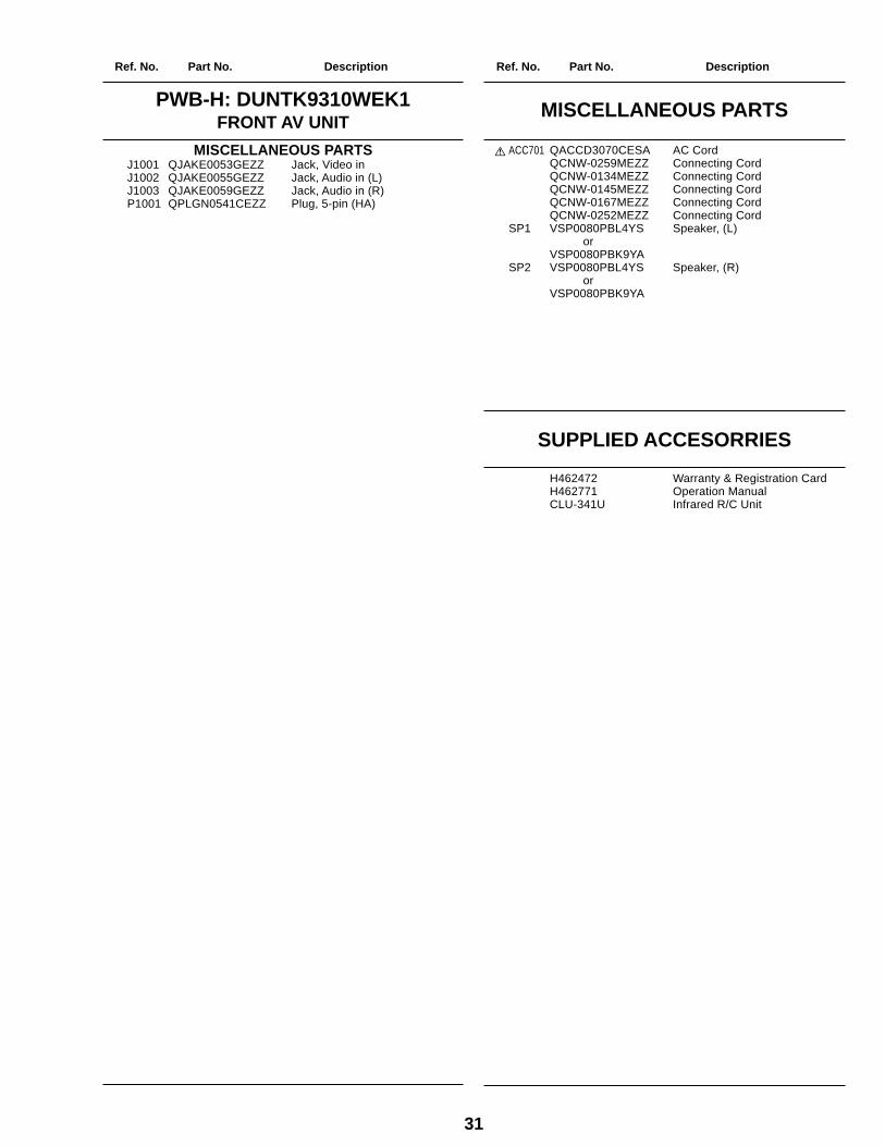
SUPPLIED ACCESORRIES
H462472 Warranty & Registration CardH462771 Operation ManualCLU-341U Infrared R/C Unit
å ACC701 QACCD3070CESA AC CordQCNW-0259MEZZ Connecting CordQCNW-0134MEZZ Connecting CordQCNW-0145MEZZ Connecting CordQCNW-0167MEZZ Connecting CordQCNW-0252MEZZ Connecting Cord
SP1 VSP0080PBL4YS Speaker, (L) orVSP0080PBK9YA
SP2 VSP0080PBL4YS Speaker, (R) orVSP0080PBK9YA
MISCELLANEOUS PARTSPWB-H: DUNTK9310WEK1FRONT AV UNIT
MISCELLANEOUS PARTSJ1001 QJAKE0053GEZZ Jack, Video inJ1002 QJAKE0055GEZZ Jack, Audio in (L)J1003 QJAKE0059GEZZ Jack, Audio in (R)P1001 QPLGN0541CEZZ Plug, 5-pin (HA)
Ref. No. Part No. Description Ref. No. Part No. Description
32
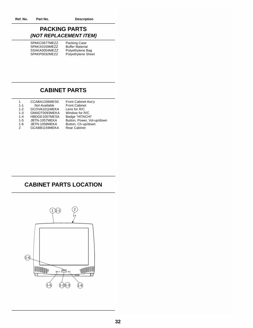
SPAKC0677MEZZ Packing CaseSPAKX0159MEZZ Buffer MaterialSSAKA0004MEZZ Polyethylene BagSPAKP0032MEZZ Polyethylene Sheet
PACKING PARTS(NOT REPLACEMENT ITEM)
CABINET PARTS
1 CCABA1336MES0 Front Cabinet Ass'y1-1 Not Available Front Cabinet1-2 GCOVA1011MEKA Lens for R/C1-3 GMADT0093MEKA Window for R/C1-4 HBDGE1007MESA Badge "HITACHI"1-5 JBTN-1057MEKA Button, Power, Vol-up/down1-6 JBTN-1058MEKA Button, Ch-up/down2 GCABB1159MEKA Rear Cabinet
CABINET PARTS LOCATION
1 21-1
1-5
1-4
1-2 1-3 1-6
Ref. No. Part No. Description Ref. No. Part No. Description
33
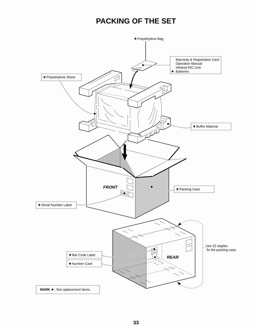
PACKING OF THE SET
REAR
Use 22 staples fix the packing case.
Bar Code Label
Packing Case
Serial Number Label
MARK : Not replacement items.
Number Card
FRONT
Buffer Material
Polyethylene Sheet
Polyethylene Bag
Warranty & Registration CardOperation ManualInfrared R/C Unit
Batteries

Ref. No. Part No. Description Ref. No. Part No. Description
34