2.8 application of panels in the production of box beams...
TRANSCRIPT
1PanelGuide (V4) Section 2.8
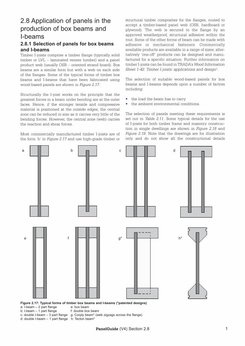
2.8 Application of panels in the production of box beams and I-beams2.8.1 Selection of panels for box beams and I-beamsTimber I-joists comprise a timber flange (typically solid timber or LVL – laminated veneer lumber) and a panel product web (usually OSB – oriented strand board). Box beams are a similar form but with a web on each side of the flanges. Some of the typical forms of timber box beams and I-beams that have been fabricated using wood-based panels are shown in Figure 2.17.
Structurally the I-joist works on the principle that the greatest forces in a beam under bending are at the outer faces. Hence, if the stronger tensile and compressive material is positioned at the outside edges, the central zone can be reduced in size as it carries very little of the bending forces. However, the central zone (web) carries the reaction and shear forces.
Most commercially manufactured timber I-joists are of the form ‘b’ in Figure 2.17 and use high-grade timber or
structural timber composites for the flanges, routed to accept a timber-based panel web (OSB, hardboard or plywood). The web is secured to the flange by an approved weatherproof, structural adhesive within the rout. Some of the other forms of beam can be made with adhesive or mechanical fasteners. Commercially available products are available in a range of sizes; alter-natively ‘one-off’ products can be designed and manu-factured for a specific situation. Further information on timber I-joists can be found in TRADA’s Wood Information Sheet 1-42: Timber I-joists: applications and design1.
The selection of suitable wood-based panels for box beams and I-beams depends upon a number of factors including:
• the load the beam has to carry• the ambient environmental conditions.
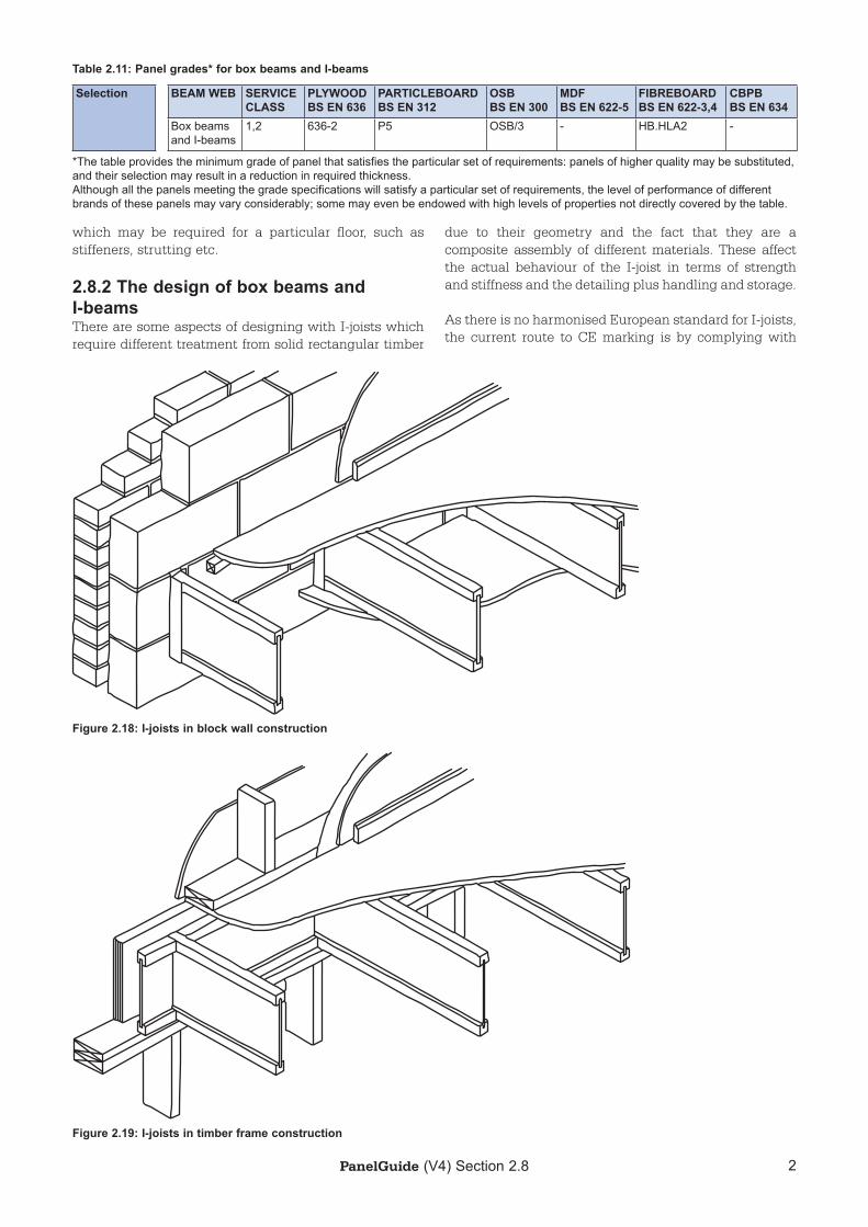
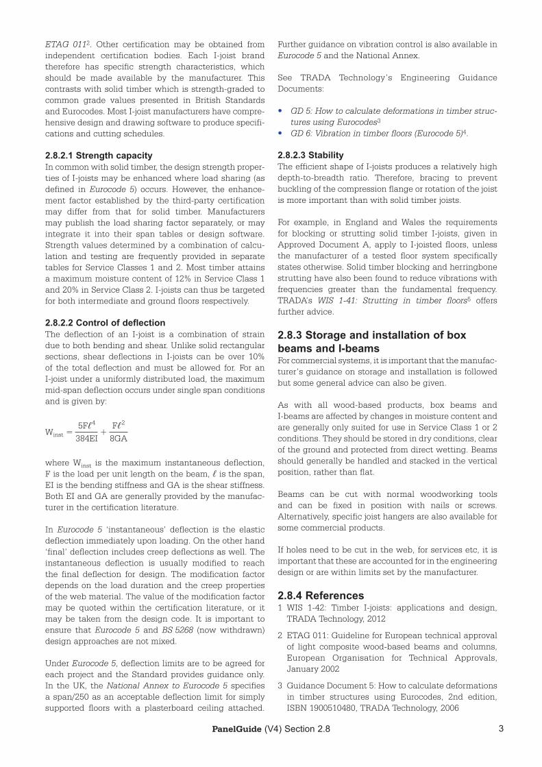
The selection of panels meeting these requirements is set out in Table 2.11. Some typical details for the use of I-joists for both timber frame and masonry construc-tion in single dwellings are shown in Figure 2.18 and Figure 2.19. Note that the drawings are for illustration only and do not show all the constructional details
ba c
e f g* h*
d
Figure 2.17: Typical forms of timber box beams and I-beams (*patented designs)a: I-beam – 2 part flange e: box beam b: I-beam – 1 part flange f: double box beam c: double I-beam – 3 part flange g: Corply beam* (web zigzags across the flange) d: double I-beam – 1 part flange h: Tecton beam*
2PanelGuide (V4) Section 2.8
due to their geometry and the fact that they are a composite assembly of different materials. These affect the actual behaviour of the I-joist in terms of strength and stiffness and the detailing plus handling and storage.
As there is no harmonised European standard for I-joists, the current route to CE marking is by complying with
which may be required for a particular floor, such as stiffeners, strutting etc.
2.8.2 The design of box beams and I-beamsThere are some aspects of designing with I-joists which require different treatment from solid rectangular timber
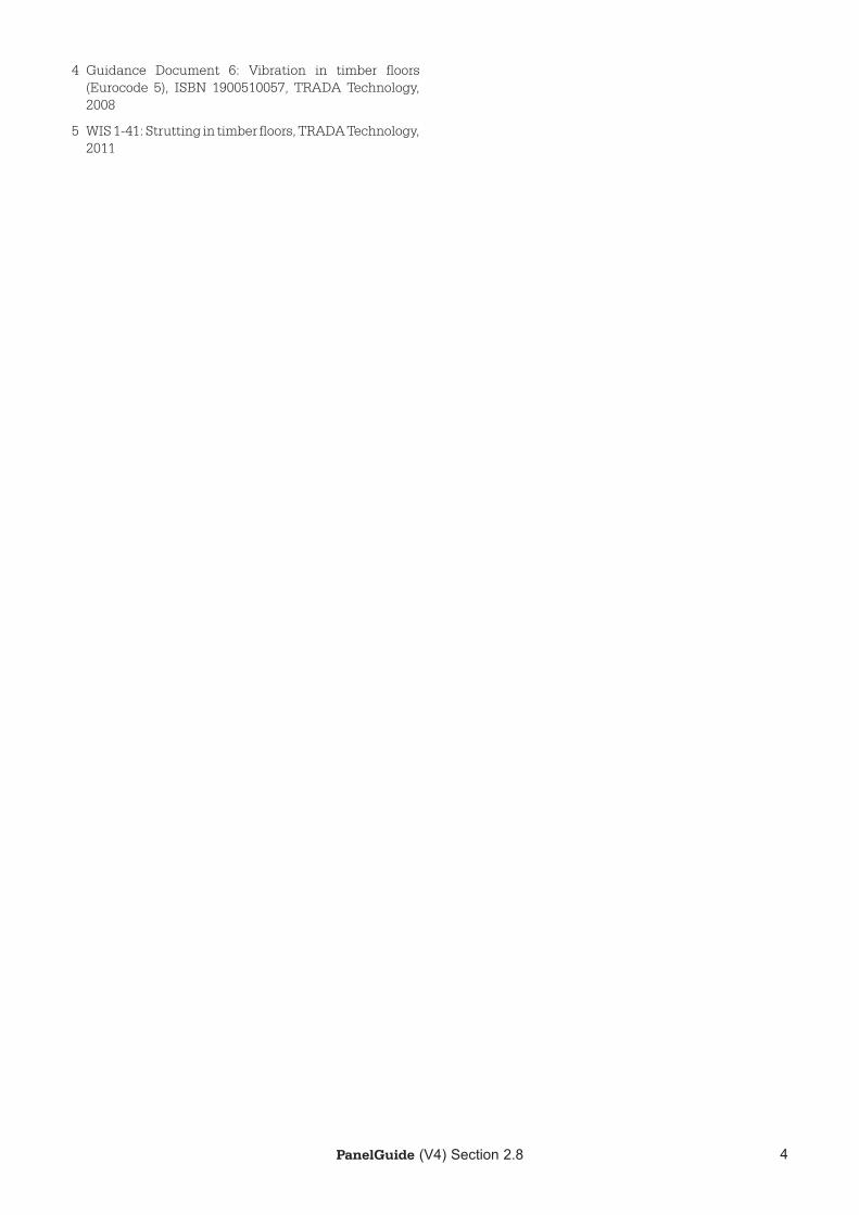
Table 2.11: Panel grades* for box beams and I-beams
Selection BEAM WEB SERVICECLASS
PLYWOODBS EN 636
PARTICLEBOARDBS EN 312
OSBBS EN 300
MDFBS EN 622-5
FIBREBOARDBS EN 622-3,4
CBPBBS EN 634
Box beams and I-beams
1,2 636-2 P5 OSB/3 - HB.HLA2 -
*The table provides the minimum grade of panel that satisfies the particular set of requirements: panels of higher quality may be substituted, and their selection may result in a reduction in required thickness. Although all the panels meeting the grade specifications will satisfy a particular set of requirements, the level of performance of different brands of these panels may vary considerably; some may even be endowed with high levels of properties not directly covered by the table.
Figure 2.18: I-joists in block wall construction
Figure 2.19: I-joists in timber frame construction
3PanelGuide (V4) Section 2.8
ETAG 0112. Other certification may be obtained from independent certification bodies. Each I-joist brand therefore has specific strength characteristics, which should be made available by the manufacturer. This contrasts with solid timber which is strength-graded to common grade values presented in British Standards and Eurocodes. Most I-joist manufacturers have compre-hensive design and drawing software to produce specifi-cations and cutting schedules.
2.8.2.1 Strength capacityIn common with solid timber, the design strength proper-ties of I-joists may be enhanced where load sharing (as defined in Eurocode 5) occurs. However, the enhance-ment factor established by the third-party certification may differ from that for solid timber. Manufacturers may publish the load sharing factor separately, or may integrate it into their span tables or design software. Strength values determined by a combination of calcu-lation and testing are frequently provided in separate tables for Service Classes 1 and 2. Most timber attains a maximum moisture content of 12% in Service Class 1 and 20% in Service Class 2. I-joists can thus be targeted for both intermediate and ground floors respectively.
2.8.2.2 Control of deflectionThe deflection of an I-joist is a combination of strain due to both bending and shear. Unlike solid rectangular sections, shear deflections in I-joists can be over 10% of the total deflection and must be allowed for. For an I-joist under a uniformly distributed load, the maximum mid-span deflection occurs under single span conditions and is given by:
5Fℓ4 Fℓ2
Winst = + 384EI 8GA
where Winst is the maximum instantaneous deflection, F is the load per unit length on the beam, ℓ is the span, EI is the bending stiffness and GA is the shear stiffness. Both EI and GA are generally provided by the manufac-turer in the certification literature.
In Eurocode 5 ‘instantaneous’ deflection is the elastic deflection immediately upon loading. On the other hand ‘final’ deflection includes creep deflections as well. The instantaneous deflection is usually modified to reach the final deflection for design. The modification factor depends on the load duration and the creep properties of the web material. The value of the modification factor may be quoted within the certification literature, or it may be taken from the design code. It is important to ensure that Eurocode 5 and BS 5268 (now withdrawn) design approaches are not mixed.
Under Eurocode 5, deflection limits are to be agreed for each project and the Standard provides guidance only. In the UK, the National Annex to Eurocode 5 specifies a span/250 as an acceptable deflection limit for simply supported floors with a plasterboard ceiling attached.
Further guidance on vibration control is also available in Eurocode 5 and the National Annex.
See TRADA Technology’s Engineering Guidance Documents:
• GD 5: How to calculate deformations in timber struc-tures using Eurocodes3
• GD 6: Vibration in timber floors (Eurocode 5)4.
2.8.2.3 StabilityThe efficient shape of I-joists produces a relatively high depth-to-breadth ratio. Therefore, bracing to prevent buckling of the compression flange or rotation of the joist is more important than with solid timber joists.
For example, in England and Wales the requirements for blocking or strutting solid timber I-joists, given in Approved Document A, apply to I-joisted floors, unless the manufacturer of a tested floor system specifically states otherwise. Solid timber blocking and herringbone strutting have also been found to reduce vibrations with frequencies greater than the fundamental frequency. TRADA’s WIS 1-41: Strutting in timber floors5 offers further advice.
2.8.3 Storage and installation of box beams and I-beamsFor commercial systems, it is important that the manufac-turer’s guidance on storage and installation is followed but some general advice can also be given.
As with all wood-based products, box beams and I-beams are affected by changes in moisture content and are generally only suited for use in Service Class 1 or 2 conditions. They should be stored in dry conditions, clear of the ground and protected from direct wetting. Beams should generally be handled and stacked in the vertical position, rather than flat.
Beams can be cut with normal woodworking tools and can be fixed in position with nails or screws. Alternatively, specific joist hangers are also available for some commercial products.
If holes need to be cut in the web, for services etc, it is important that these are accounted for in the engineering design or are within limits set by the manufacturer.
2.8.4 References1 WIS 1-42: Timber I-joists: applications and design,
TRADA Technology, 2012
2 ETAG 011: Guideline for European technical approval of light composite wood-based beams and columns, European Organisation for Technical Approvals, January 2002
3 Guidance Document 5: How to calculate deformations in timber structures using Eurocodes, 2nd edition, ISBN 1900510480, TRADA Technology, 2006
PanelGuide (V4) Section 2.8 4
4 Guidance Document 6: Vibration in timber floors (Eurocode 5), ISBN 1900510057, TRADA Technology, 2008
5 WIS 1-41: Strutting in timber floors, TRADA Technology, 2011

1PanelGuide (V4)
PanelGuide Version 4ISBN 978-1-909594-21-0
Published in 2014 by the Wood Panel Industries Federation, TRADA Technology Ltd (a BM TRADA company), and the National Panel Products Division (a division of the Timber Trades Federation)
Previous editions are listed in Annex 4 of the PanelGuide
This is a technical book for professionals in the built environment sector. While every effort is made to ensure the accuracy of the advice given, the project partners cannot accept liability for loss or damage however caused arising from the use of the information supplied
All rights reserved. PanelGuide may be downloaded and printed for single use only. You must request the permission of the copyright owners if you wish to extract content from the PanelGuide or use it for any other purpose
© Wood Panel Industries Federation, TRADA Technology Ltd (a BM TRADA company), and the National Panel Products Division (a division of the Timber Trades Federation)
Unless otherwise stated in the caption, all photographs and illustrations included in the Panel Guide are © Wood Panel Industries Federation, TRADA Technology Ltd and the National Panel Products Division
Revisions to PanelGuide Version 4 contributed by Ian Rochester (WPIF), Vic Kearley (BM TRADA) and Nick Boulton (TTF)
Produced by the publishing team at BM TRADA, the official publisher for the Timber Research and Development Association
Contact details for the PanelGuide project partners are:
WOODPANELINDUSTRIESFEDERATION
Wood Panel Industries FederationAutumn Business ParkDysart RoadGranthamLincsNG31 7EUTel: 01476 512 381Email: [email protected]: www.wpif.org.uk
Timber Research and Development AssociationChiltern HouseStocking LaneHughenden ValleyHigh WycombeBucksHP14 4NDTel: 01494 569 603Email: [email protected]: www.trada.co.uk
National Panel Products DivisionTimber Trades FederationThe Building Centre26 Store StreetLondonWC1E 7BTTel: 020 3205 0067Email: [email protected]: www.ttf.co.uk
Produced by BM TRADA, the official publisher for TRADA
Email: [email protected]: www.bmtradagroup.com