280 motor version - gws (grand wing system u.s.a....
TRANSCRIPT
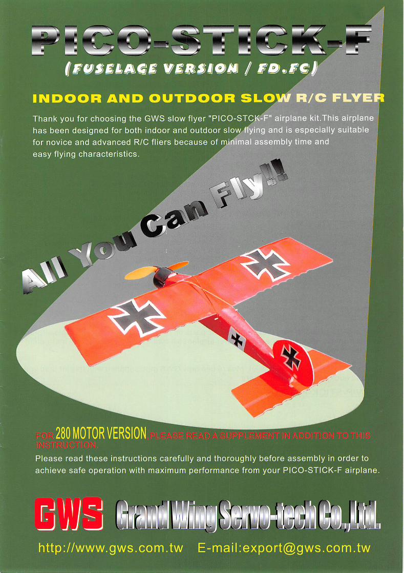
280 MOTOR VERSION
Please read these instructions carefully and thoroughly before assembly In order to
achieve safe operation with maximum performance from your PICO-STICK-F airplane.
http://www.gws.com.tw E-mail:[email protected]
vou
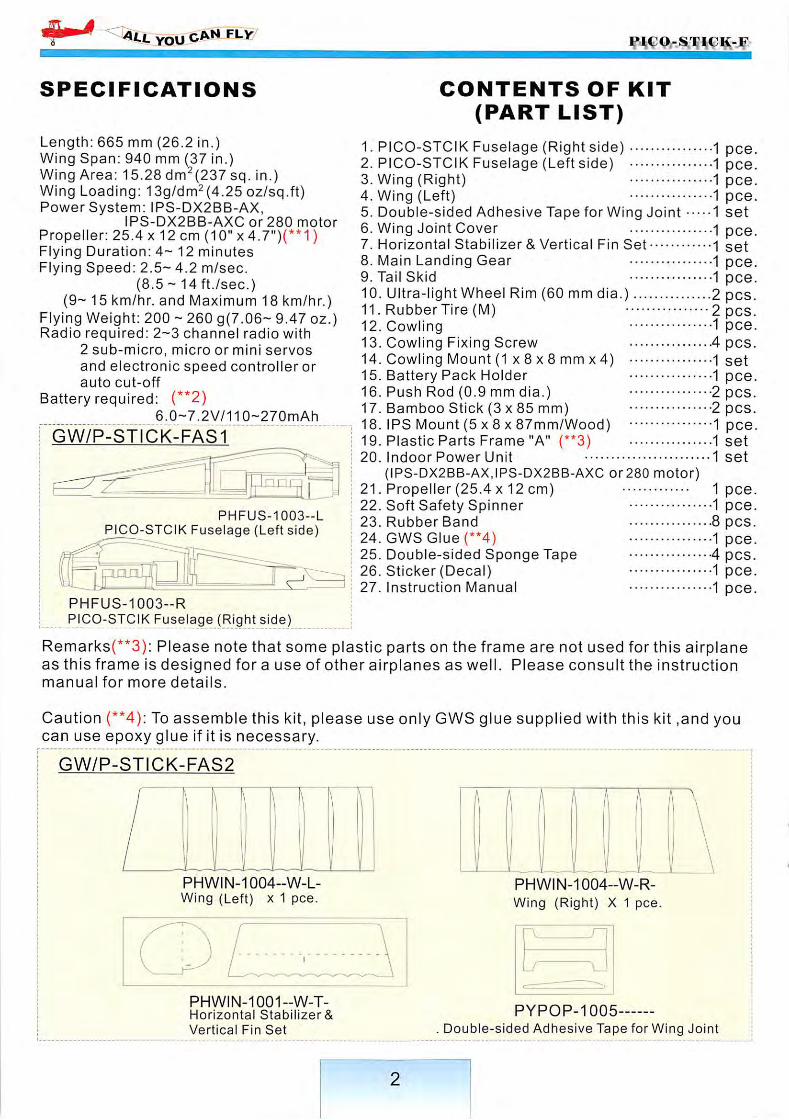
SPECIFICATIONS
Length: 665 mm (26.2 in.)Wing Span: 940 mm (37 in.)Wing Area: 15.28 dm^(237 sq. in.)Wing Loading: 13g/dm2(4.25 oz/sq.ft)Power System: IPS-DX2BB-AX,
IPS-DX2BB-AXC or 280 motorPropeller: 25.4 x 12 cm (10" x 4.7")(**1)Flying Duration: 4- 12 minutesFlying Speed: 2.5- 4.2 m/sec.
(8.5 - 14 ft./sec.)(9- 15 km/hr. and Maximum 18 km/hr.)
Flying Weight: 200 - 260 g(7.06- 9.47 oz.)Radio required: 2-3 channel radio with
2 sub-micro, micro or mini servosand electronic speed controller orauto cut-off
Battery required: (**2)6.0-7.2V/110-270mAh
GW/P-STICK-FAS1
•.an
PHFUS-1003-LPICO-STCIK Fuselage (Left side)
iinQ
PHFUS-1003-RPICO-STCIK Fuselage (Right side)
CONTENTS OF KIT
(PART LIST)
1. PICO-STCIK Fuselage (Right side) 1 pee.2. PICO-STCIK Fuselage (Left side) 1 pee.3. Wing (Right) 1 pee.4. Wing (Left) 1 pee.5. Double-sided Adhesive Tape for Wing Joint 1 set6. Wing Joint Cover 1 pee.7. Horizontal Stabilizer & Vertical Fin Set l set8. Main Landing Gear 1 pee.9. Tail Skid 1 pee.10. Ultra-light Wheel Rim (60 mm dia.) 2 pes.11. Rubber Tire (M) 2 pes.12. Cowling 1 pee.13. Cowling Fixing Screw 4 pes.14. Cowling Mount (1 x8x8mmx4) 1 set15. Battery Pack Holder 1 pee.16. Push Rod (0.9 mm dia.) 2 pes.17. Bamboo Stick (3 x 85 mm) 2 pes.18. IPS Mount (5 x 8 X87mm/Wood) 1 pee,19. Plastic Parts Frame "A" (**3) 1 set20. Indoor Power Unit 1 set
(IPS-DX2BB-AX,IPS-DX2BB-AXC or280 motor)21. Propeller (25.4 X12 cm) 1 pee.22. Soft Safety Spinner 1 pee.23. Rubber Band 8 pes.24. GWSGIue(**4) 1 pee.25. Double-sided Sponge Tape 4 pes.26. Sticker (Decal) 1 pee.27. Instruction Manual 1 pee.
Rennarks(**3): Please note that some plastie parts on the frame are not used forthis airplaneas this frame is designed for a use of other airplanes as well. Please consult the instructionmanual for more details.
Caution (**4): To assemble this kit, please use only GWS glue supplied with this kit ,and youcan use epoxy glue if it is necessary.
GW/P-.STICK-FAS2
PHWIN-1004-W-L-Wing (Left) x 1 pee.
PHW1N-1001--W-T-Horizontal Stabilizer&
Vertieal Fin Set
"'W
PHW1N-1004-W-R-
Wing (Right) X 1 pee.
PYPOP-1005
Double-sided Adhesive Tape for Wing Joint
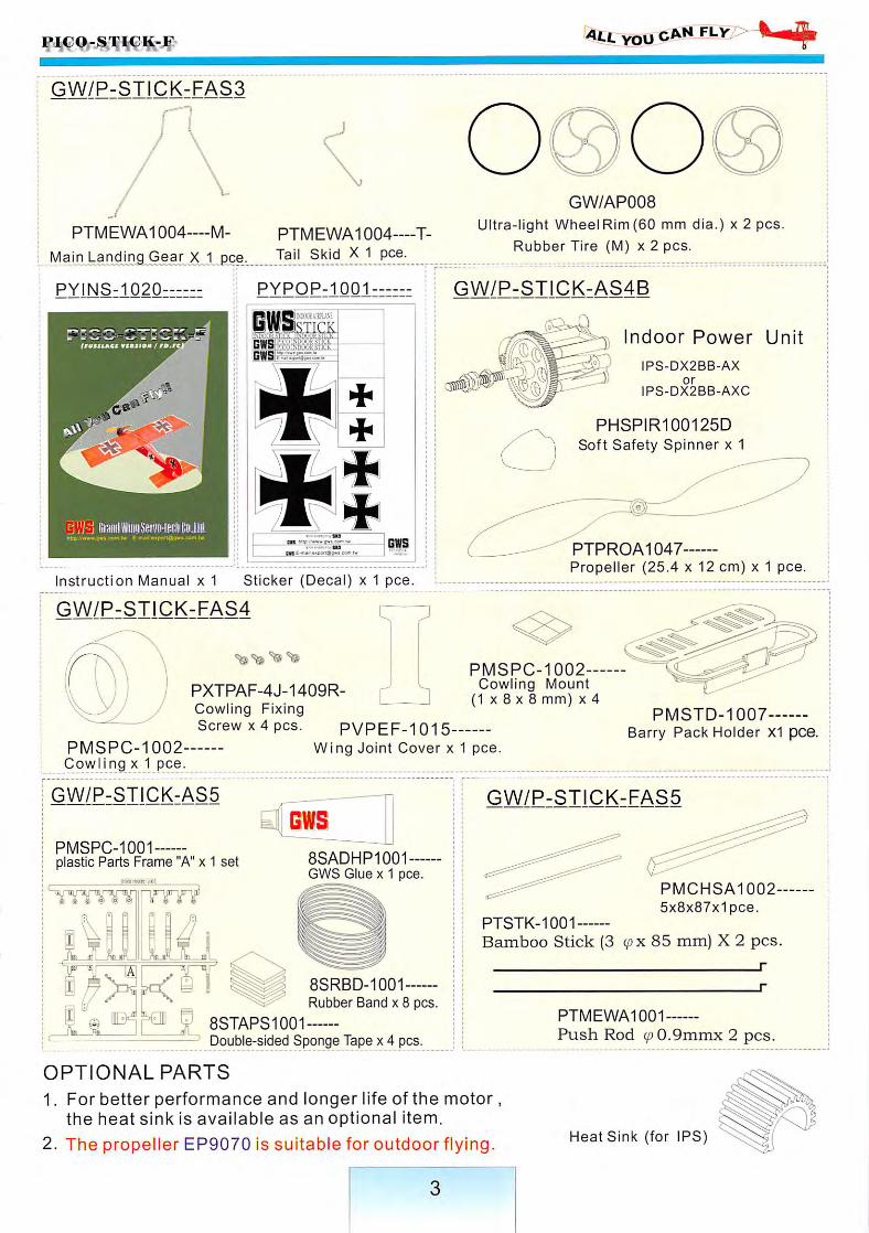
GW/P-ST1CK-FAS3
PTMEWA1004—M- PTMEWA1004—T-
Main Landing Gear X 1 pee..
allyou cANMV/>^-ii^
GW/AP008
Ultra-light WheelRim(60 mm dia.) x 2 pos.
Rubber Tire (M) x 2 pos.
PYINS-1020 PYPOP-1001 GW/P-STICK-AS4B
cjViij (mniiWiiiiiSmo-iBciib'DJiil.Rffa Awi»**S'«$ c«n« t» E-mA't «<po't \ -jf 'c 5-r
STICK
Instruction Manual x 1 Sticker (Decal) x 1 pee
GW/P-STICK-FAS4 r
PXTPAF-4J-1409R- ^ ^Cowling FixingScrew X4 pcs. PVPEF-1015-
Indoor Power Unit
IPS-DX2BB-AXor
IPS-DX2BB-AXC
PHSPIR100125D
Soft Safety Spinner x 1
PTPROA1047Propeller (25.4 x 12 cm) x 1 pee.
PMSPC-1002Cowling Mount
{1 X8 X 8 mm) x 4
PMSPC-1002-Cowling x 1 pee.
Wing Joint Cover x 1 pee.
GW/P-STICK-FAS5
PMSTD-1007Barry Pack Holder XI pce.
GW/P-STICK-AS5
PMSPC-1001plastic Parts Frame "A" x 1 set
8SRBD-1001Rubber Band x 8 pcs.
f 8STAPS1001Double-sided Sponge Tape x 4 pcs.
8SADHP1001GWS Glue X1 pce.
PMCHSA1002-
5x8x87x1pce.PTSTK-1001
Bamboo Stick (3 (px85 mm) X 2 pcs.
r
r
PTMEWA1001
Push Rod (/)0.9mmx 2 pcs.
OPTIONAL PARTS
1. For better performance and longer life of the motor,the heat sink is available as an optional item.
2. The propeller EP9070 is suitable for outdoor flying. Heat Sink (for IPS)
you fly
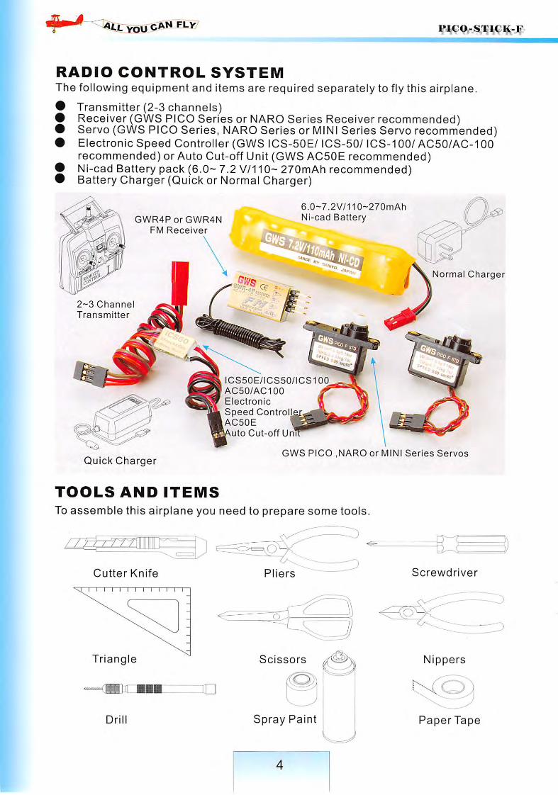
RADIO CONTROL SYSTEMThe following equipment and items are required separately to fly this airplane.
• Transmitter (2-3 channels)• Receiver (GWS PICO Series or NARO Series Receiver recommended)• Servo (GWS PICO Series, NARO Series or MINI Series Servo recommended)• Electronic Speed Controller (GWS ICS-50E/ ICS-50/ ICS-100/ AC50/AC-100
recommended) or Auto Cut-off Unit (GWS AC50E recommended)• Ni-cad Battery pack (6.0- 7.2 V/110- 270mAh recommended)• Battery Charger (Quick or Normal Charger)
2-3 Channel
Transmitter
GV\/R4P or GWR4N
FM Receiver
6.0-7.2V/110--270mAh
Ni-cad Battery
ICS50E/ICS50/ICS100
AC50/AC100
Electronic
Speed ControllAC50E
uto Cut-off Unl
Normal Charger
Quick ChargerGWS PICO ,NARO or MINI Series Servos
TOOLS AND ITEMS
To assemble this airplane you need to prepare some tools.
Cutter Knife Pliers
Triangle Scissors
Spray Paint
Screwdriver
Nippers
Paper Tape
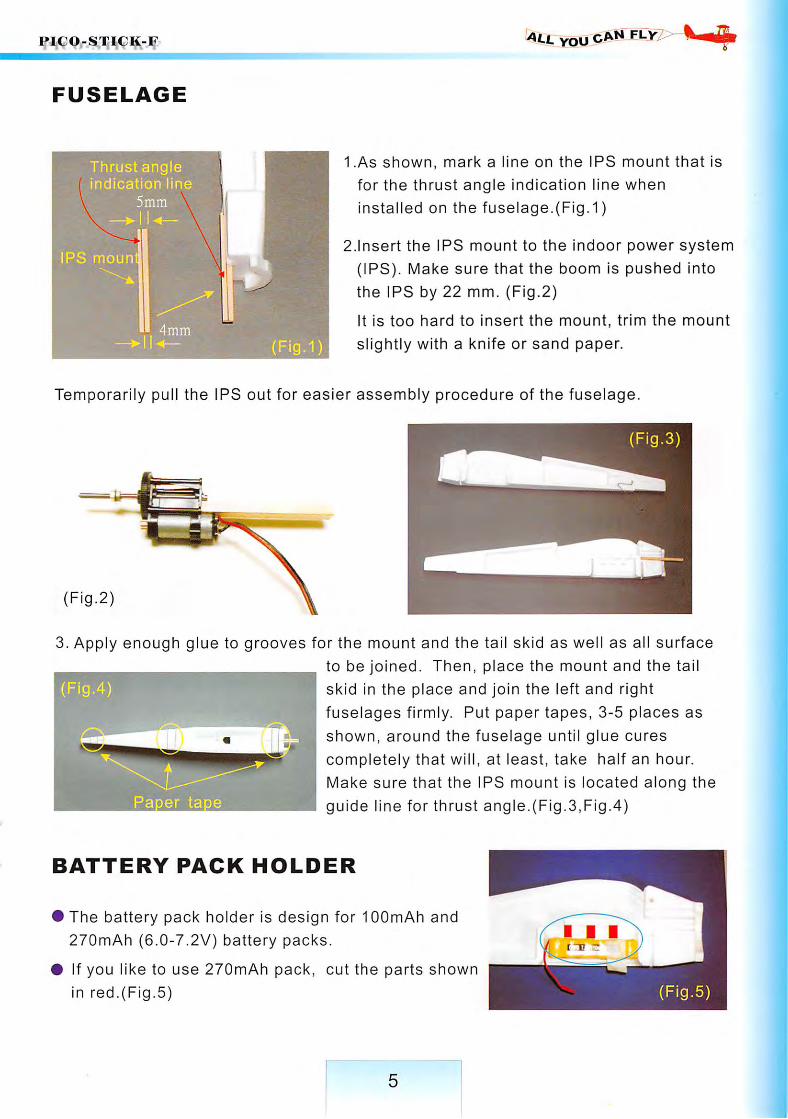
FUSELAGE
Thrust angleindication line
5min
IPS moun
(Fig.i)
YOU CAN
1.As shown, mark a line on the IPS mount that is
for the thrust angle indication line when
installed on the fuselage.(Fig.1)
2.Insert the IPS mount to the indoor power system
(IPS). Make sure that the boom is pushed into
the IPS by 22 mm. (Fig.2)
It is too hard to insert the mount, trim the mount
slightly with a knife or sand paper.
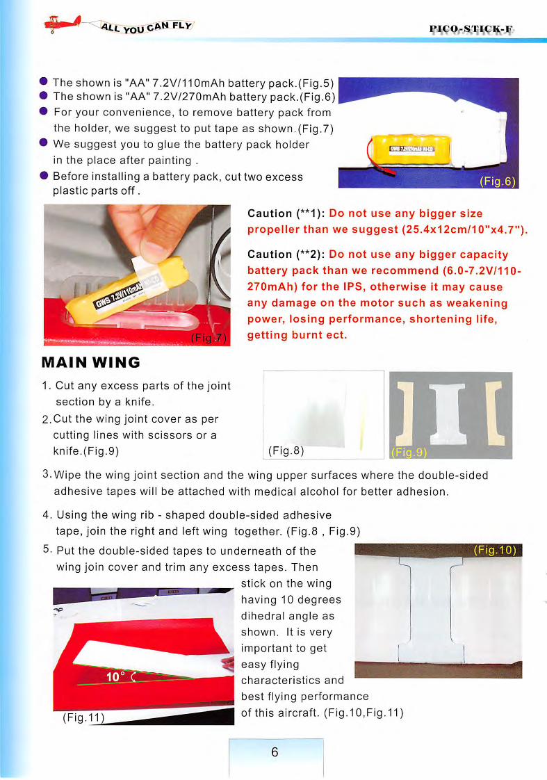
Temporarily pull the IPS out for easier assembly procedure of the fuselage.
Fig.3
(Fig.2)
3. Apply enough glue to grooves for the mount and the tail skid as well as all surface
to be joined. Then, place the mount and the tail
skid in the place and join the left and right
fuselages firmly. Put paper tapes, 3-5 places as
shown, around the fuselage until glue cures
completely that will, at least, take half an hour.
Make sure that the IPS mount is located along the
guide line for thrust angle.(Fig.3,Fig.4)
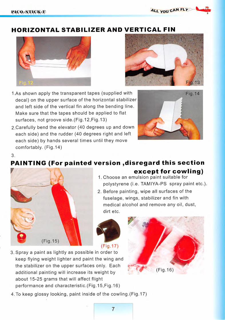
BATTERY PACK HOLDER
• The battery pack holder is design for lOOmAh and
270mAh (6.0-7.2V) battery packs.
• If you like to use 270mAh pack, cut the parts shown
in red.(Fig.5) (Fig.5)
4^- you fly
The shown is "AA" 7.2V/110mAh battery pack.(Fig.5)The shown is "AA" 7.2V/270mAh battery pack.(Fig.6)For your convenience, to remove battery pack from
the holder, we suggest to put tape as shown.(Fig.7)
We suggest you to glue the battery pack holder
in the place after painting .
Before installing a battery pack, cut two excessplastic parts off.
c(Fig.6)
Caution (**1): Do not use any bigger size
propeller than we suggest (25.4x12cm/10"x4.7").
Caution (**2): Do not use any bigger capacity
battery pack than we recommend (6.0-7.2V/110-
270mAh) for the IPS, otherwise it may cause
any damage on the motor such as weakening
power, losing performance, shortening life,
getting burnt ect.
MAIN WING
1. Cut any excess parts of the joint
section by a knife.
2.Cut the wing joint cover as per
cutting lines with scissors or a
knife.(Fig.9) (Flg.8)]1[
(Fig.9)
3. Wipe the wing joint section and the wing upper surfaces where the double-sidedadhesive tapes will be attached with medical alcohol for better adhesion.
4. Using the wing rib - shaped double-sided adhesive
tape, join the right and left wing together. (Fig.8 , Fig.9)
5- Put the double-sided tapes to underneath of thewing join cover and trim any excess tapes. Then
stick on the wing
having 10 degrees
dihedral angle as
shown. It is very
important to get
easy flying
characteristics and
best flying performance
of this aircraft. (Fig.10,Fig.11)
6
(Fig.10)
all you FLY^P^KmS^
HORIZONTAL STABILIZER AND VERTICAL FIN
1.As shown apply the transparent tapes {supplied with
decal) on the upper surface of the horizontal stabilizer
and left side of the vertical fin along the bending line.
Make sure that the tapes should be applied to flat
surfaces, not groove side.(Fig.12,Fig.13)
2.Carefully bend the elevator (40 degrees up and down
each side) and the rudder (40 degrees right and left
each side) by hands several times until they move
comfortably. (Fig.14)
3.
PAINTING (For painted version ,disregard this sectionf except for cowling)
1. Choose an emulsion paint suitable for
polystyrene (i.e. TAMIYA-PS spray paint etc.).
Illl^ I 2. Before painting, wipe all surfaces of the} i fuselage, wings, stabilizer and fin with
medical alcohol and remove any oil, dust,
dirt etc.
(Fig.15)(Fig.17)
3. Spray a paint as lightly as possible in order to
keep flying weight lighter and paint the wing and
the stabilizer on the upper surfaces only. Each
additional painting will increase its weight by
about 15-25 grams that will affect flight
performance and characteristic.(Fig.15,Fig.16)
4.To keep glossy looking, paint inside of the cowling.(Fig.17)
Fig.14
(Fig.16)

you FLy PlCO-STlC^-f,
MAIN LANDING GEAR
(Fig.19
(Fig.20(Fig.18)
1. Install the wheel rims on the main landing gear and push on the stoppers (A-1).Carefully Install the rubber tires on the grooves of the wheel rims and apply a
little amount of an Instant glue to secure. (Fig.18,Fig.19)
2. Insert the landing gear into the slot on the fuselage and apply enough glue to theslot (Flg.20)
HORIZONTAL STABILIZER AND VERTICAL FIN
Flg.22
1. Use a triangle to determine the center of
horizontal stabilizer as shown. (Fig.21)
2. Apply glue to the tall of the fuselage and
stick the horizontal stabilizer. Put pins to
secure until glue cures and make sure
that the stabilizer Is glued to the fuselage
securely and horlzontally.(Flg.22,Flg.23)
8

Fig.24)
3. Make sure the fin is perpendicular to
the stabilizer. (Fig.26)
Fig.26
you fly
2. Insert the vertical fin to the fuselage
slot and mark a guide line with a
pencil. Then, apply glue to the root
(about 3 mm) and bottom of the fin
and insert it the slot as shown.(Fig .24 .Fig .25)
I
Fig.27
4. Stick the decals onto the fuselage, wing and fin in accordance with some pictures
in this instruction and outer display box.(Fig.27)
MAIN WING MOUNTING
1. For mounting the main wing on the fuselage,
insert two bamboo sticks (3 x 85mm) to the
holes on the side wall of the fuselage and
apply glue to secure.(Fig.28,Fig.29)
(Fig.28) Fig.29
9

YOU
(Fig.30)
2.To mount the main wing, use 2-4 rubber band
and hook them crossed as shown.(Fig.30)
INDOOR POWER SYSTEM (IPS),
COWLING, PROPELLER AND SPINNER
*iW
(Fig.31-2)
1. Holding the IPS mount (wood part), insert the mount to the Indoor Power System
(IPS). Make sure that the mount is pushed into the IPS by 22mm. The motor
wires should go through a hole to inside of the fuselage.(Fig.31-1,Fig.31-2)
Flg.32
Fig.33)
2. As shown glue 4 cowling mounts to the
nose of the fuselage. Put the cowling
in a position and drill 1.2mm dia. holes,
then fix the cowling with 4 screws (1.4
X 9mm) .(Fig.32,Fig.33)
3. Install the propeller and fix it firmly with
the washer and nut, then push on the
spinner.(Fig.34)
(Fig.34)
10
YOU fly
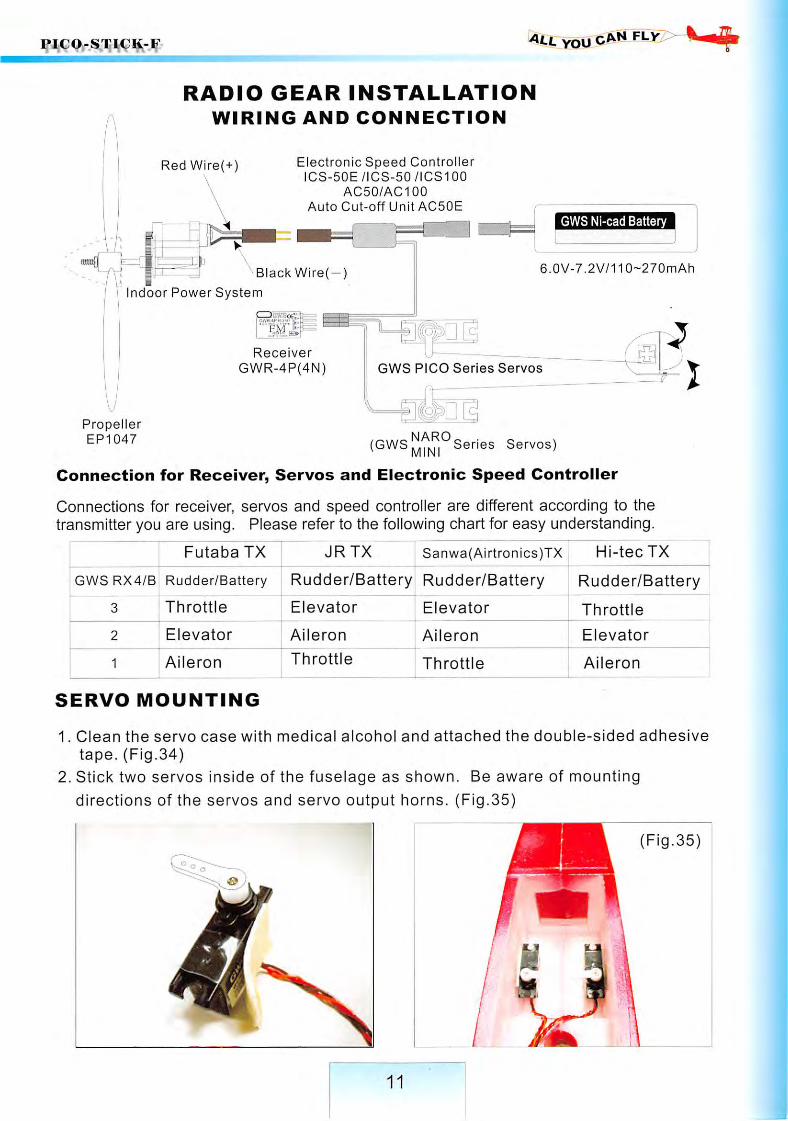
RADIO GEAR INSTALLATION
WIRING AND CONNECTION
Red Wire(+ Electronic Speed ControllerICS-50E/ICS-50/ICS100
AC50/AC100
Auto Cut-off Unit AC50E
GWS Nl-cad Battery
Black Wire(—; 6.0V-7.2V/110-270mAh
Indoor Power System
lii^
Receiver
GWR-4P(4N)
""W'l-
PropellerEP1047
GWS PICO Series Servos
(GWS Series Servos)
Connection for Receiver, Servos and Electronic Speed Controller
Connections for receiver, servos and speed controller are different according to thetransmitter you are using. Please refer to the following chart for easy understanding.
Futaba TX
GWSRX4/B Rudder/Battery
3 Throttle
Elevator
Aileron
SERVO MOUNTING
JRTX Sanwa(Airtronics)TX Hi-tec TX
Rudder/Battery Rudder/Battery | Rudder/BatteryElevator
Aileron
Throttle
Elevator
Aileron
Throttle
Throttle
Elevator
Aileron
1. Glean the servo case with medical alcohol and attached the double-sided adhesive
tape. (Fig.34)
2. Stick two servos inside of the fuselage as shown. Be aware of mounting
directions of the servos and servo output horns. (Fig.35)
Fig.35
11
4^ you
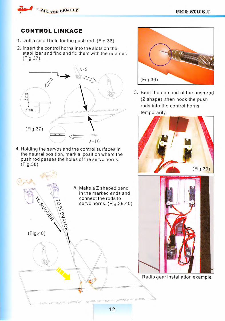
CONTROL LINKAGE
1. Drill a small holeforthe push rod. (Fig.36)
2. Insert the control horns into the slots on thestabilizer and find and fix them with the retainer.
(Fig.37)
\ A-5
(Fig.37)
A-10
4. Holding the servos and the control surfaces inthe neutral position, mark a position where thepush rod passes the holes of the servo horns.(Fig.38)
(Fig.36
3. Bent the one end of the push rod
(Z shape) ,then hook the push
rods into the control horns
temporarily.
(Fig.39)
5. Make a Z shaped bendin the marked ends and
connect the rods to
servo horns. (Fig.39,40)
(Fig.40)
Radio gear Installation example

PICO-STICK-F all YOU can flvt^^^
TIPS AND HINTS
PREFLIGHT CHECKS
it is always recommended that you charge your transmitter and receiver batteries as
well as the battery pack for the motor before attempting to fly your airplane.
The Center of Gravity (C.G./balancing point) is located 50^60mm back from the
leading edge of the main wing. After all radio gear and the battery pack is installed,
check the C.G. point of your airplane. If the balancing point is offset, move the
receiver and speed controller forward or vice versa until you find the recommended
balancing point.
Check the radio gear and the linkage thoroughly on the ground and make sure that
all the control surfaces are working properly and correctly before attempting to take
off your airplane.
We recommend that you should check the range of your radio before the first flight
of the day.
FLIGHT
Always turn on the receiver last after turning on the transmitter, and shut off the
receiver first before turning off the transmitter.
You can take off you airplane from the smooth surface ground, normally 1-3 meters
for run and take off.
If you are hand-launching your model, move the throttle stick up fully and see if the
motor is running at the maximum rpm. Then, throw your model to the air horizontally
as shown and apply up elevator as model climbs at a shallow angle. If you launch
your airplane at a steep angle, upward or downward, it may result in a crash of your
model.
13
you
CAUTION
# If you are only beginner for the radio control model flying, do not attempt to fly yourmodel without any assistance or advice from advanced and expert fliers.
# Do not fly close to buildings, electric power lines, or roads. Do not fly near otherpeople who are not aware of what you are doing.
IVEVER FLY OVER PEOPLES^ HEADS OR CARS
# Fly on a calm day. Gusty winds will make it hard for you until you learn to control your
aircraft well. Turbulence caused by wind blowing over near by trees and buildings will
make it very difficult for you to fly. Pick an open area and wait until the wind is calm.
# If you are going to attempt to fly your airplane in the indoor arena, closer attentionand more safety preparation must be made in order to avoid any possible casualties
LIMITED WARRANTY
# Your new GWS PICO-STICK-F airplane kit is warranted against defects in material
and workmanship.
# This warranty does not apply to any component parts, which have been improperly
installed, handled, abused, damaged, modified and used.
WARNING:
# If you are a beginner to R/C model flight then we strongly recommend you seek advice
from your supplier and local model flying club before attempting to fly your model.
# This model is not a toy and must be assembled and used responsibility in order for
successful flight to be achieved.
# Improper use of this model may lead to injury or damage to persons or property.
GWS ad their distributors will not accept any responsibility for any injury or damage
arising from improper use of this model.
E & O E
14