2800 series -...
TRANSCRIPT
VLT® 2800 Series
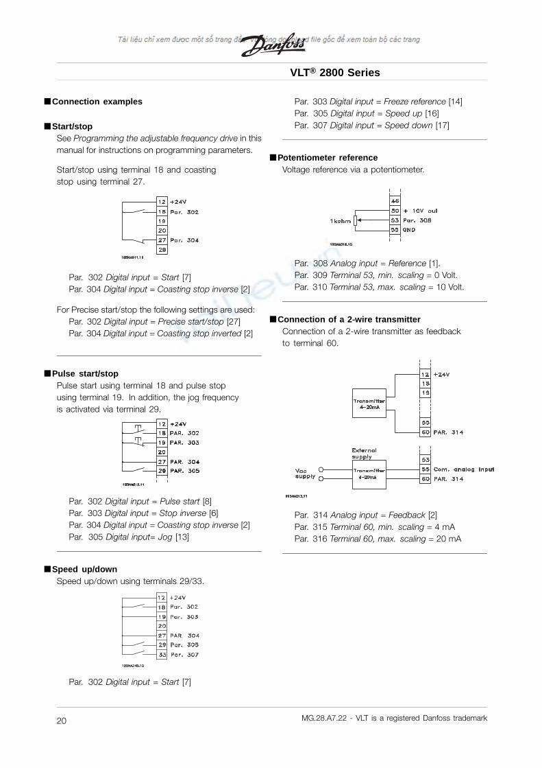
■ Connection examples
■ Start/stopSee Programming the adjustable frequency drive in thismanual for instructions on programming parameters.
Start/stop using terminal 18 and coastingstop using terminal 27.
Par. 302 Digital input = Start [7]Par. 304 Digital input = Coasting stop inverse [2]
For Precise start/stop the following settings are used:Par. 302 Digital input = Precise start/stop [27]Par. 304 Digital input = Coasting stop inverted [2]
■ Pulse start/stopPulse start using terminal 18 and pulse stopusing terminal 19. In addition, the jog frequencyis activated via terminal 29.
Par. 302 Digital input = Pulse start [8]Par. 303 Digital input = Stop inverse [6]Par. 304 Digital input = Coasting stop inverse [2]Par. 305 Digital input= Jog [13]
■ Speed up/downSpeed up/down using terminals 29/33.
Par. 302 Digital input = Start [7]
Par. 303 Digital input = Freeze reference [14]Par. 305 Digital input = Speed up [16]Par. 307 Digital input = Speed down [17]
■ Potentiometer referenceVoltage reference via a potentiometer.
Par. 308 Analog input = Reference [1].Par. 309 Terminal 53, min. scaling = 0 Volt.Par. 310 Terminal 53, max. scaling = 10 Volt.
■ Connection of a 2-wire transmitterConnection of a 2-wire transmitter as feedbackto terminal 60.
Par. 314 Analog input = Feedback [2]Par. 315 Terminal 60, min. scaling = 4 mAPar. 316 Terminal 60, max. scaling = 20 mA
MG.28.A7.22 - VLT is a registered Danfoss trademark20
VLT® 2800 Series
Inst
alla
tion
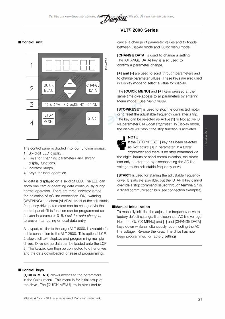
■ Control unit
The control panel is divided into four function groups:1. Six-digit LED display .2. Keys for changing parameters and shifting
display functions.3. Indicator lamps.4. Keys for local operation.
All data is displayed on a six-digit LED. The LED canshow one item of operating data continuously duringnormal operation. There are three indicator lampsfor indication of AC line connection (ON), warning(WARNING) and alarm (ALARM). Most of the adjustablefrequency drive parameters can be changed via thecontrol panel. This function can be programmed asLocked in parameter 018, Lock for data changes,to prevent tampering or local data entry.
A keypad, similar to the larger VLT 6000, is available forcable connection to the VLT 2800. This optional LCP2 allows full text displays and programming multipledrives. Drive set up data can be loaded onto the LCP2. The keypad can then be connected to other drivesand the data downloaded for ease of programming.
■ Control keys[QUICK MENU] allows access to the parametersin the Quick menu. This menu is for initial setup ofthe drive. The [QUICK MENU] key is also used to
cancel a change of parameter values and to togglebetween Display mode and Quick menu mode.
[CHANGE DATA] is used to change a setting.The [CHANGE DATA] key is also used toconfirm a parameter change.
[+] and [-] are used to scroll through parameters andto change parameter values. These keys are also usedin Display mode to select a value for display.
The [QUICK MENU] and [+] keys pressed at thesame time give access to all parameters by enteringMenu mode. See Menu mode.
[STOP/RESET] is used to stop the connected motoror to reset the adjustable frequency drive after a trip.The key can be selected as Active [1] or Not active [0]via parameter 014 Local stop/reset. In Display mode,the display will flash if the stop function is activated.
NOTEIf the [STOP/RESET ] key has been selectedas Not active [0] in parameter 014 Localstop/reset and there is no stop command via
the digital inputs or serial communication, the motorcan only be stopped by disconnecting the AC linevoltage to the adjustable frequency drive.
[START] is used for starting the adjustable frequencydrive. It is always available, but the [START] key cannotoverride a stop command issued through terminal 27 ora digital communication bus (see connection examples).
■ Manual initializationTo manually initialize the adjustable frequency drive tofactory default settings, first disconnect AC line voltage.Hold the [QUICK MENU] and [+] and [CHANGE DATA]keys down while simultaneously reconnecting the ACline voltage. Release the keys. The drive has nowbeen programmed for factory settings.
MG.28.A7.22 - VLT is a registered Danfoss trademark 21
VLT® 2800 Series
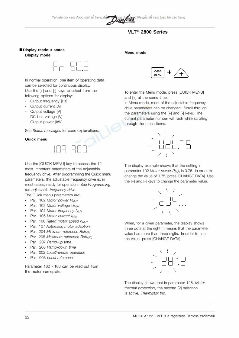
■ Display readout statesDisplay mode
In normal operation, one item of operating datacan be selected for continuous display.Use the [+] and [-] keys to select from thefollowing options for display:- Output frequency [Hz]- Output current [A]- Output voltage [V]- DC bus voltage [V]- Output power [kW]
See Status messages for code explanations.
Quick menu
Use the [QUICK MENU] key to access the 12most important parameters of the adjustablefrequency drive. After programming the Quick menuparameters, the adjustable frequency drive is, inmost cases, ready for operation. See Programmingthe adjustable frequency drive.The Quick menu parameters are:• Par. 102 Motor power PM,N
• Par. 103 Motor voltage UM,N
• Par. 104 Motor frequency fM,N
• Par. 105 Motor current IM,N
• Par. 106 Rated motor speed nM,N
• Par. 107 Automatic motor adaption.• Par. 204 Minimum reference RefMIN
• Par. 205 Maximum reference RefMAX
• Par. 207 Ramp-up time• Par. 208 Ramp-down time• Par. 002 Local/remote operation• Par. 003 Local reference
Parameter 102 - 106 can be read out fromthe motor nameplate.
Menu mode
To enter the Menu mode, press [QUICK MENU]and [+] at the same time.In Menu mode, most of the adjustable frequencydrive parameters can be changed. Scroll throughthe parameters using the [+] and [-] keys. Thecurrent parameter number will flash while scrollingthrough the menu items.
The display example shows that the setting inparameter 102 Motor power PM,N is 0.75. In order tochange the value of 0.75, press [CHANGE DATA]. Usethe [+] and [-] keys to change the parameter value.
When, for a given parameter, the display showsthree dots at the right, it means that the parametervalue has more than three digits. In order to seethe value, press [CHANGE DATA].
The display shows that in parameter 128, Motorthermal protection, the second [2] selectionis active, Thermistor trip.
MG.28.A7.22 - VLT is a registered Danfoss trademark22

VLT® 2800 Series
Inst
alla
tion
Programming the adjustable frequency drive
NOTEThe motor must be stopped to changeparameter data.
Program the drive in accordance with thefollowing procedure:1. Press the [QUICK MENU] key to enter
the Quick menu.2. Scroll through the Quick menu using the
[+] and [-] keys.3. Change the data values by first pressing
[CHANGE DATA] key4. and then change the parameter value with
the [+] and [-] keys.5. Press [CHANGE DATA] again to accept the change
or [QUICK MENU] to cancel the change. Press[QUICK MENU] once more to exit Quick menumode and enter Display mode. (The drive willdefault from Quick menu mode to Display modein 2 minutes if no activity has taken place.)
NOTEEnter parameters 102 through 106 data, atminimum, to ready the drive for operation.Data for parameters 102 through 106 can
be read from the motor nameplate.
Automatic motor tuningAutomatic motor tuning (AMT) measures statorresistance RS without the motor turning. This meansthat the motor is not delivering any torque. AMTcan optimize adjustment of the adjustable frequencydrive to the motor. For best possible tuning, it isrecommended that AMT be performed on a coldmotor. Repeated AMT runs can cause motor heating,resulting in an increase in the stator resistance. Asa rule, however, this is not critical. (See parameter107, Automatic motor tuning, AMT, descriptionfor more detail before running AMT.)
Perform AMT in accordance with thefollowing procedure:
1. Press the [QUICK MENU] key to enterQuick menu mode
2. Use the [+] key to scroll to parameter 107.3. In parameter 107, Automatic motor tuning,
"107" will now flash.
4. Press [CHANGE DATA] and use the [+] keyto select data value [2], Optimization on (AMTSTART). [2] will now flash.
5. Press [START] key to activate AMT. "107" willnow flash and dashes will move from left toright in the data value field.
6. When "107" appears once more with the datavalue [0], AMT is complete. Press [STOP/RESET]to save the motor data into the drive memory.
7. "107" will then continue to flash with the datavalue [0]. Press [QUICK MENU] to exit Menumode and enter Display mode.
MG.28.A7.22 - VLT is a registered Danfoss trademark 23
VLT® 2800 Series
■ Status messagesFrThe drive displays the present output frequencyin Hertz [Hz].
IoThe drive displays the present output currentin Amps [A].
UoThe drive displays the present output voltage in Volts [V].
UdThe drive displays the DC bus voltage in Volts [V].
PoThe drive displays the calculated output in kilowatt [kW].
notrunThis message is shown if an attempt is made to changea parameter value while the motor is running. Stopthe motor to change the parameter value.
LCPThis message is shown if an LCP 2 control unit isconnected and the [QUICK MENU] or [CHANGE DATA]key is pressed. With an LCP 2 control unit connected,it is only possible to change parameters via the LCP 2.
HAHA indicates the drive is in Hand mode, whichmeans the drive’s speed is controlled at the keypadwith the [+] and [-] keys. Only output frequency isshown on the display in Hand mode.
■ Hand / Auto mode operationDuring Auto mode operation, the adjustable frequencydrive receives an external reference through the controlterminals as analog or digital signals. In Auto mode, usethe [+] and [-] keys to scroll through the display of drivestatus messages. In Hand mode, it is possible to controlthe speed of the drive locally through the keypad.
On the control terminals, the following control signalswill remain active when Hand mode is activated:• Hand Start (LCP2)• Off Stop (LCP2)• Auto Start (LCP2)• Reset• Coasting Stop Inverse• Reset and Coasting Stop Inverse• Quick Stop Inverse• Stop Inverse• Reversing• DC Braking Inverse• Setup Select LSB• Setup Select MSB• Thermistor• Precise Stop Inverse• Precise Stop/Start• Jog• Stop Command Via Serial Comm.
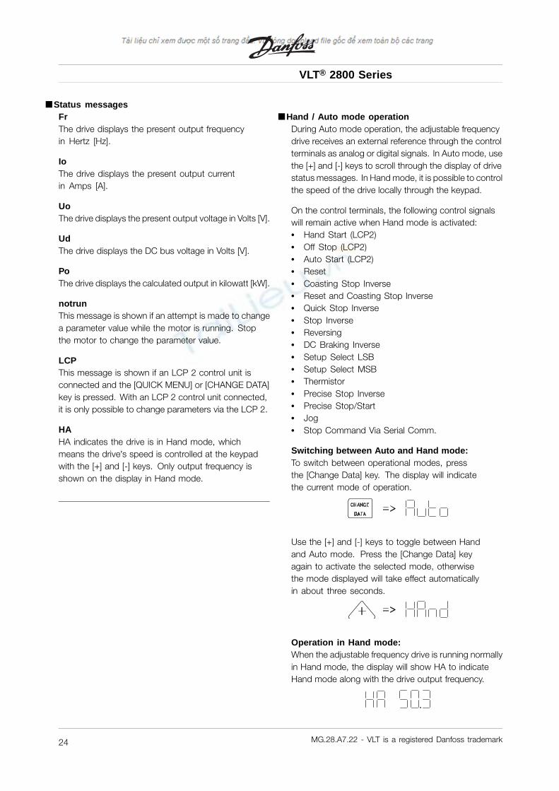
Switching between Auto and Hand mode:To switch between operational modes, pressthe [Change Data] key. The display will indicatethe current mode of operation.
Use the [+] and [-] keys to toggle between Handand Auto mode. Press the [Change Data] keyagain to activate the selected mode, otherwisethe mode displayed will take effect automaticallyin about three seconds.
Operation in Hand mode:When the adjustable frequency drive is running normallyin Hand mode, the display will show HA to indicateHand mode along with the drive output frequency.
MG.28.A7.22 - VLT is a registered Danfoss trademark24

VLT® 2800 Series
Inst
alla
tion
In Hand mode, the local speed reference can beincreased or decreased with the [+] and [-] keys:
In Hand mode, the [+] and [-] keys are also used totoggle through status messages. Press and hold the[Change Data] key for approximately 3 seconds. Whenthe display begins to flash, use the [+] and [-] keysto change the drive status display. The displays aretemporary and will default back to output frequency.
NOTEParameter 020 can be used to disableHand mode operation.
■ Warnings/alarmsWarnings or alarms appear in the LED display as anumerical code [Err. xx]. A warning is displayed untilthe fault has been corrected, while an alarm will flashuntil the [STOP/RESET] key is pressed. The table inWarnings/alarms messages in this manual explainsthe various warnings and alarms, and whether a faultlocks the adjustable frequency drive. After a Triplocked fault, cut off the AC line supply and correct thefault. Then reconnect the AC line supply and pressthe [STOP/RESET] key. The adjustable frequencydrive is now reset and ready. See Warnings/alarmsmessages in this manual for more detail.
MG.28.A7.22 - VLT is a registered Danfoss trademark 25
VLT® 2800 Series
■ Special conditions
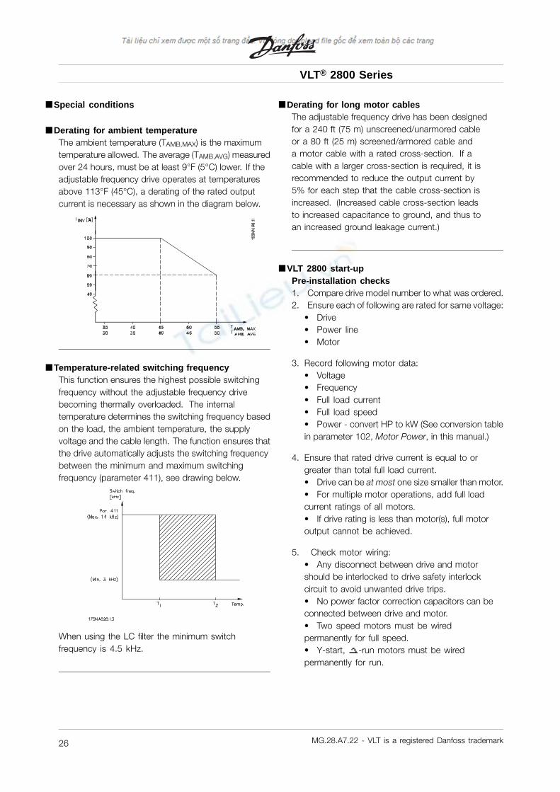
■ Derating for ambient temperatureThe ambient temperature (TAMB,MAX) is the maximumtemperature allowed. The average (TAMB,AVG) measuredover 24 hours, must be at least 9°F (5°C) lower. If theadjustable frequency drive operates at temperaturesabove 113°F (45°C), a derating of the rated outputcurrent is necessary as shown in the diagram below.
■ Temperature-related switching frequencyThis function ensures the highest possible switchingfrequency without the adjustable frequency drivebecoming thermally overloaded. The internaltemperature determines the switching frequency basedon the load, the ambient temperature, the supplyvoltage and the cable length. The function ensures thatthe drive automatically adjusts the switching frequencybetween the minimum and maximum switchingfrequency (parameter 411), see drawing below.
When using the LC filter the minimum switchfrequency is 4.5 kHz.
■ Derating for long motor cablesThe adjustable frequency drive has been designedfor a 240 ft (75 m) unscreened/unarmored cableor a 80 ft (25 m) screened/armored cable anda motor cable with a rated cross-section. If acable with a larger cross-section is required, it isrecommended to reduce the output current by5% for each step that the cable cross-section isincreased. (Increased cable cross-section leadsto increased capacitance to ground, and thus toan increased ground leakage current.)
■ VLT 2800 start-upPre-installation checks1. Compare drive model number to what was ordered.2. Ensure each of following are rated for same voltage:
• Drive• Power line• Motor
3. Record following motor data:• Voltage• Frequency• Full load current• Full load speed• Power - convert HP to kW (See conversion tablein parameter 102, Motor Power, in this manual.)
4. Ensure that rated drive current is equal to orgreater than total full load current.• Drive can be at most one size smaller than motor.• For multiple motor operations, add full loadcurrent ratings of all motors.• If drive rating is less than motor(s), full motoroutput cannot be achieved.
5. Check motor wiring:• Any disconnect between drive and motorshould be interlocked to drive safety interlockcircuit to avoid unwanted drive trips.• No power factor correction capacitors can beconnected between drive and motor.• Two speed motors must be wiredpermanently for full speed.• Y-start, -run motors must be wiredpermanently for run.
MG.28.A7.22 - VLT is a registered Danfoss trademark26