29 emi & filtering
TRANSCRIPT
29 – Interference & Filtering29 – Interference & Filtering
• When you interfere with Broadcast Stations
• When you interfere with Television Stations
• When you interfere with Audio devices (Stereos etc)
• When you interfere with other Amateurs
• When you interfere with telephone devices
• When you interfere with garage doors etc etc
When your Signals InterfereWhen your Signals InterfereBCI and TVI:BCI and TVI: Interference is inevitable from time to time. You should face the problem when Interference is inevitable from time to time. You should face the problem when
it arises and not worry about it beforehandit arises and not worry about it beforehand
Make sure You are “Clean” FirstMake sure You are “Clean” FirstMake sure all the apparatus in your own home do not cause any interference Make sure all the apparatus in your own home do not cause any interference
with any of your devices in your home. You should be “Holier than thou”with any of your devices in your home. You should be “Holier than thou”
BCIBCIThe BC Receiver should have a RF Amp stage and be connected to an The BC Receiver should have a RF Amp stage and be connected to an outside Antenna. It is interference only when you interfere with an actual outside Antenna. It is interference only when you interfere with an actual
station.station.
Audio Devices (Stereos – Radiograms – Record Players etc)Audio Devices (Stereos – Radiograms – Record Players etc)These devices are not designed to be radio receivers. Courteously discuss the These devices are not designed to be radio receivers. Courteously discuss the
matter with the owner and advice him to contact the supplier of the device or matter with the owner and advice him to contact the supplier of the device or his agent to have the deficiency cured. Courteously is the operative word.his agent to have the deficiency cured. Courteously is the operative word.
What kind of EMI have you got?What kind of EMI have you got?
Troubleshooting an EMI problem is a three-step process, Troubleshooting an EMI problem is a three-step process, and all three steps are equally important: and all three steps are equally important:
Identify the problem Identify the problem Diagnose the problem Diagnose the problem Cure the problem. Cure the problem.
There is the “Social” aspect of any Interference problemThere is the “Social” aspect of any Interference problem
You don’t want to be “The Neighbour from Hell!”You don’t want to be “The Neighbour from Hell!”
Either your neighbour or the Either your neighbour or the RSM RI will contact you first.RSM RI will contact you first.
Don’t Panic! Check your operating activities against your logbookDon’t Panic! Check your operating activities against your logbook
It is a good idea to keep a logbook!It is a good idea to keep a logbook!
Is it you? Have you changed antennas? Is it you? Have you changed antennas? Have you built a new Amplifier or changed modes? Have you built a new Amplifier or changed modes? What did your neighbour actually see or hear?What did your neighbour actually see or hear?
Show “Concern” but do not admit responsibility. Show “Concern” but do not admit responsibility. Wait for tests to be conducted. Get all the details, time, date andWait for tests to be conducted. Get all the details, time, date and nature of the interference. Do not Worry!nature of the interference. Do not Worry!
Do not hesitate to contact the RSM by phone and it will Do not hesitate to contact the RSM by phone and it will help to contact a local radio club member for advicehelp to contact a local radio club member for advice

Causes of InterferenceCauses of Interference
The Technical cause of interference may be:The Technical cause of interference may be:
A) At the Transmitter installation or,A) At the Transmitter installation or,
B) At the Receiver installation or,B) At the Receiver installation or,
C) Somewhere else or,C) Somewhere else or,
D) Combinations of all of those above D) Combinations of all of those above

Interference TestingInterference TestingA) Have another Ham operate your equipment while you A) Have another Ham operate your equipment while you communicate with him by a VHF handheld. Observe what happens to communicate with him by a VHF handheld. Observe what happens to colour, sound, channels etc and note it in your notebook. Have a colour, sound, channels etc and note it in your notebook. Have a cursory look at the installation of his antenna and feedline and note cursory look at the installation of his antenna and feedline and note those details down. Be very non-committal with your communication those details down. Be very non-committal with your communication to the neighbour.to the neighbour.
B) Substitute another TV set know to be TVI free in your location.B) Substitute another TV set know to be TVI free in your location.
C) Confine your tests to operational ones. Do not remove the back of C) Confine your tests to operational ones. Do not remove the back of his set.his set.
D) Keep your tests short. Do not offer an opinion. Withdraw and D) Keep your tests short. Do not offer an opinion. Withdraw and consult textbooks and others for advice and decide on a course of consult textbooks and others for advice and decide on a course of action.action.
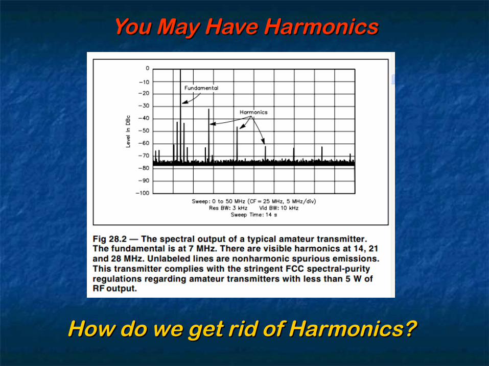
You May Have HarmonicsYou May Have Harmonics
How do we get rid of Harmonics?How do we get rid of Harmonics?

Curing Harmonic InterferenceCuring Harmonic Interference (( Harmonic and Fundamental Overload Problems)Harmonic and Fundamental Overload Problems)
Your transmitter operates from 1.8Mhz to 30 Mhz in various bands. Your transmitter operates from 1.8Mhz to 30 Mhz in various bands. The 2nd harmonics exist from 3.6Mhz to 60Mhz and 3The 2nd harmonics exist from 3.6Mhz to 60Mhz and 3 rdrd harmonics operate right up to 90Mhz. 4harmonics operate right up to 90Mhz. 4 thth, 5, 5 thth and 6 and 6 thth harmonics are harmonics are all over the television receiver frequencies. You need a device on all over the television receiver frequencies. You need a device on your transmitter which “passes” Low frequencies (1.8 – 30 Mhz) your transmitter which “passes” Low frequencies (1.8 – 30 Mhz) and is extremely “lossy” above 30 Mhz. and is extremely “lossy” above 30 Mhz.
This is a This is a LOW PASS FILTERLOW PASS FILTER
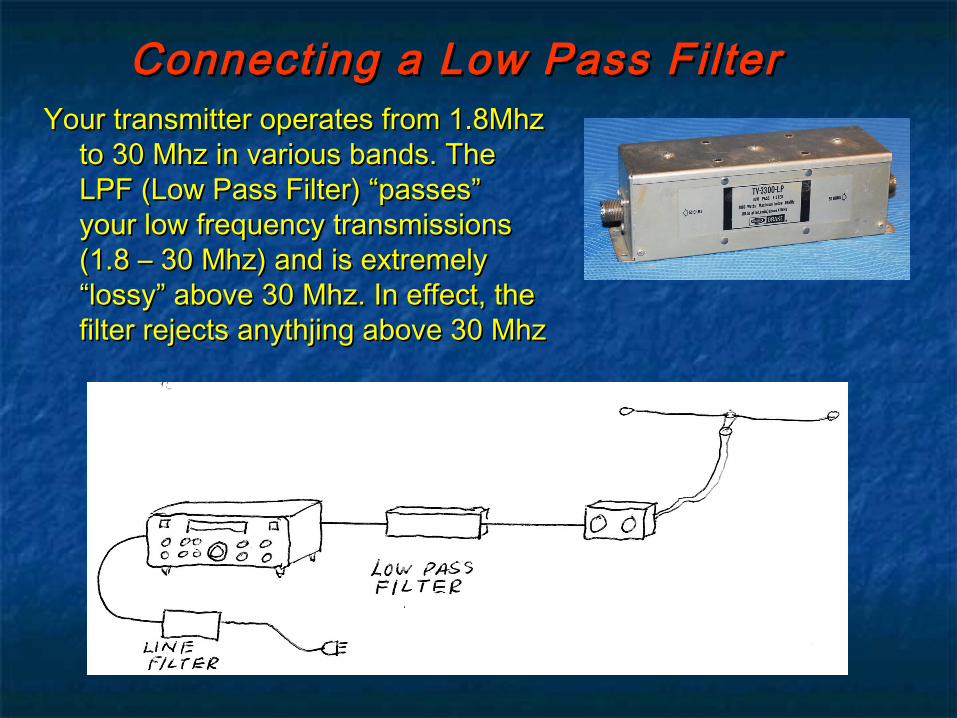
Connecting a Low Pass FilterConnecting a Low Pass FilterYour transmitter operates from 1.8Mhz Your transmitter operates from 1.8Mhz
to 30 Mhz in various bands. The to 30 Mhz in various bands. The LPF (Low Pass Filter) “passes” LPF (Low Pass Filter) “passes” your low frequency transmissions your low frequency transmissions (1.8 – 30 Mhz) and is extremely (1.8 – 30 Mhz) and is extremely “lossy” above 30 Mhz. In effect, the “lossy” above 30 Mhz. In effect, the filter rejects anythjing above 30 Mhzfilter rejects anythjing above 30 Mhz
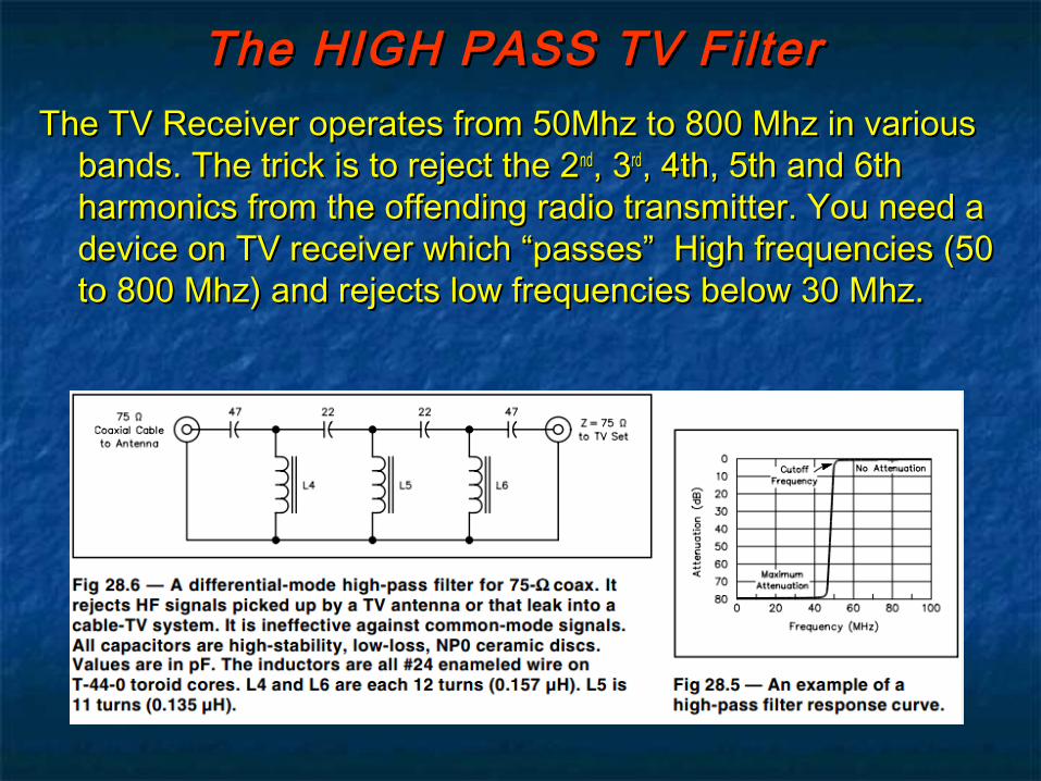
The TV Receiver operates from 50Mhz to 800 Mhz in various The TV Receiver operates from 50Mhz to 800 Mhz in various bands. The trick is to reject the 2bands. The trick is to reject the 2ndnd, 3, 3rdrd, 4th, 5th and 6th , 4th, 5th and 6th harmonics from the offending radio transmitter. You need a harmonics from the offending radio transmitter. You need a device on TV receiver which “passes” High frequencies (50 device on TV receiver which “passes” High frequencies (50 to 800 Mhz) and rejects low frequencies below 30 Mhz. to 800 Mhz) and rejects low frequencies below 30 Mhz.
The HIGH PASS TV FilterThe HIGH PASS TV Filter

The TV Receiver operates from The TV Receiver operates from 50Mhz to 800 Mhz in various 50Mhz to 800 Mhz in various bands. The High Pass Filters will bands. The High Pass Filters will “pass” high frequencies (50 to 800 “pass” high frequencies (50 to 800 Mhz) while rejecting low Mhz) while rejecting low frequencies below 30 Mhz. frequencies below 30 Mhz.
Connecting a High Pass TV FilterConnecting a High Pass TV Filter
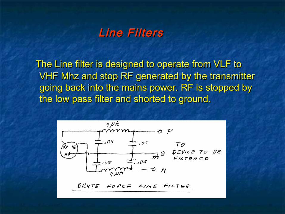
The Line filter is designed to operate from VLF to The Line filter is designed to operate from VLF to VHF Mhz and stop RF generated by the transmitter VHF Mhz and stop RF generated by the transmitter going back into the mains power. RF is stopped by going back into the mains power. RF is stopped by the low pass filter and shorted to ground.the low pass filter and shorted to ground.
Line Filters Line Filters
What else can cause interference?What else can cause interference?
• Electric Blanket switches (They tend to regularly click on and off)
• Refrigerator thermostats (They tend to regularly click on and off)
• Washer and Dryer electronics (Tends to change pitch with various wash cycles)
• TV Sets (Generates a Line Oscillator signal around 15 Khz with harmonics)
• Some Garage Door electronics (Continuous signals on 1 or more frequencies)
• Poor Commutation in an electric motor (On continuously with motor on)
• Plasma TVs
Some Broadband noise generators to beware of!Some Broadband noise generators to beware of!
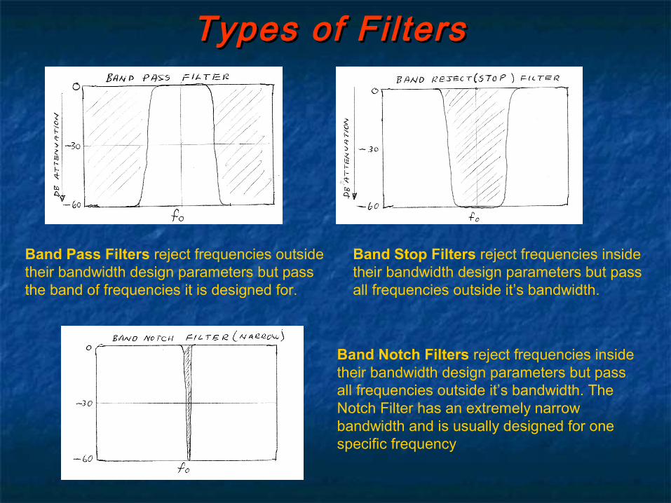
Types of Fil tersTypes of Fil ters
Band Pass Filters reject frequencies outside their bandwidth design parameters but pass the band of frequencies it is designed for.
Band Stop Filters reject frequencies inside their bandwidth design parameters but pass all frequencies outside it’s bandwidth.
Band Notch Filters reject frequencies inside their bandwidth design parameters but pass all frequencies outside it’s bandwidth. The Notch Filter has an extremely narrow bandwidth and is usually designed for one specific frequency

Active FiltersActive FiltersFilters can be active or passive. Passive filters are comprised of inductors and capacitors and are used for the suppression of unwanted signals and interference.
Active filters use amplifying devices such as transistors or integrated circuits with feedback applied to achieve the required filter characteristics.
The “Operational amplifier” is an active device with features making it particularly suitable for filter applications up to a few megahertz. This diagram shows a typical example.
Active Filters can have a very high gain but with negative feedback applied, are usually operated to produce a circuit with unity gain. The input impedance to such a circuit can be very high.
These circuits are compact, and able to have variable Q, centre, and cut-off frequencies. The circuit gain and performance can be adjusted by changes to the feedback network.
Op Amp Active Fil ter
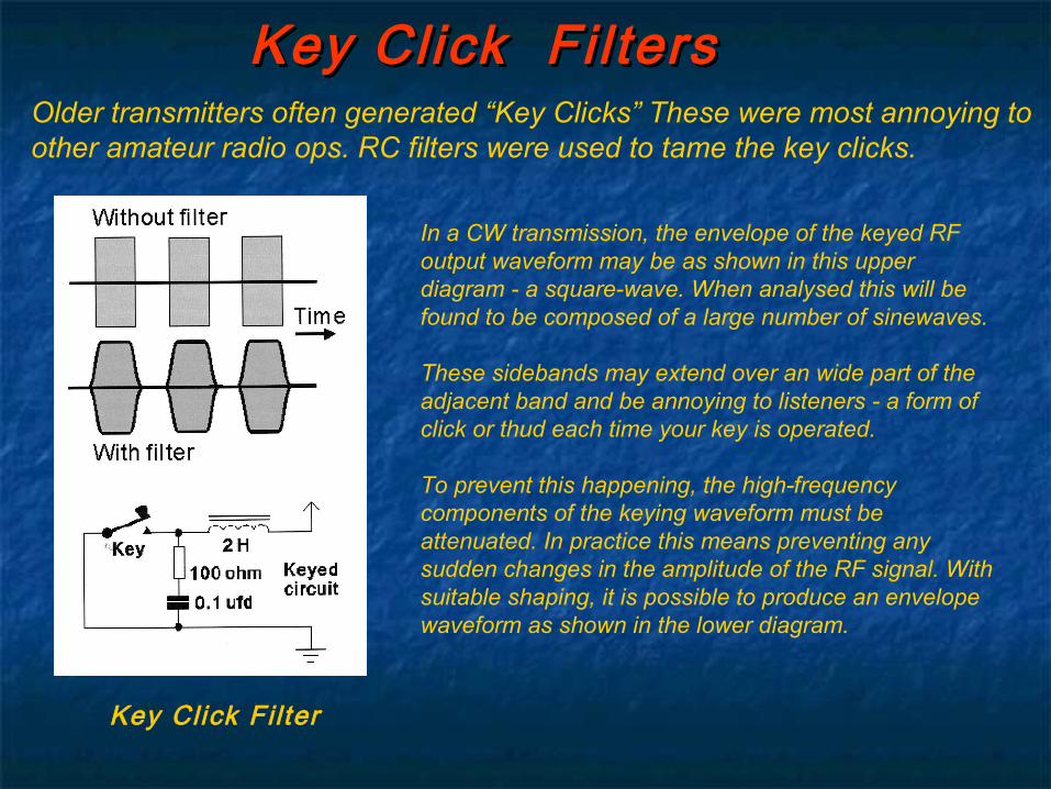
Key Click Fi ltersKey Click Fi ltersOlder transmitters often generated “Key Clicks” These were most annoying to other amateur radio ops. RC filters were used to tame the key clicks.
In a CW transmission, the envelope of the keyed RF output waveform may be as shown in this upper diagram - a square-wave. When analysed this will be found to be composed of a large number of sinewaves.
These sidebands may extend over an wide part of the adjacent band and be annoying to listeners - a form of click or thud each time your key is operated.
To prevent this happening, the high-frequency components of the keying waveform must be attenuated. In practice this means preventing any sudden changes in the amplitude of the RF signal. With suitable shaping, it is possible to produce an envelope waveform as shown in the lower diagram.
Key Click Filter

We Are Done !We Are Done !