29008181r001 3g3070 v3.5 im na ulc ul draft 11 final
TRANSCRIPT

3G30703G (HSPA) WIRELESS ALARM
COMMUNICATOR
INSTALLATION MANUALV3.5
WARNING: This manual contains information on limitations regarding productuse and function and information on the limitations as to liability of the manu-facturer. The entire manual should be carefully read.

i
Introduction . . . . . . . . . . . . . . . . . . . . . . . . . . . . . . . . . . . . . . . . . . . . .1
Features . . . . . . . . . . . . . . . . . . . . . . . . . . . . . . . . . . . . . . . . . . . . . . . .1
Technical Specifications . . . . . . . . . . . . . . . . . . . . . . . . . . . . . . . . . . .1
Ratings . . . . . . . . . . . . . . . . . . . . . . . . . . . . . . . . . . . . . . . . . . . . . . . . .1
Identification of Parts . . . . . . . . . . . . . . . . . . . . . . . . . . . . . . . . . . . . . .2
Description . . . . . . . . . . . . . . . . . . . . . . . . . . . . . . . . . . . . . . . . . . . . . .3
Installing the 3G3070 . . . . . . . . . . . . . . . . . . . . . . . . . . . . . . . . . . . . . .4
Connecting the 3G3070 . . . . . . . . . . . . . . . . . . . . . . . . . . . . . . . . . . . .4
Status LEDS . . . . . . . . . . . . . . . . . . . . . . . . . . . . . . . . . . . . . . . . . . . . .5
Operating Principles . . . . . . . . . . . . . . . . . . . . . . . . . . . . . . . . . . . . . .6
Simulated Landline Mode . . . . . . . . . . . . . . . . . . . . . . . . . . . . . . . . . .6
Panel Transmission Monitoring (PTM) . . . . . . . . . . . . . . . . . . . . . . . . .6
Wireless Communications Sequence . . . . . . . . . . . . . . . . . . . . . . . . .6
Inputs . . . . . . . . . . . . . . . . . . . . . . . . . . . . . . . . . . . . . . . . . . . . . . . . . .6
Outputs . . . . . . . . . . . . . . . . . . . . . . . . . . . . . . . . . . . . . . . . . . . . . . . .7
Activating the Outputs . . . . . . . . . . . . . . . . . . . . . . . . . . . . . . . . . . . . .7
Swinger Shutdown . . . . . . . . . . . . . . . . . . . . . . . . . . . . . . . . . . . . . . . .7
Hardware Default . . . . . . . . . . . . . . . . . . . . . . . . . . . . . . . . . . . . . . . . .7
Low Power Radio Shutdown . . . . . . . . . . . . . . . . . . . . . . . . . . . . . . . .8
CONNECT 24 Remote Programming . . . . . . . . . . . . . . . . . . . . . . . . .8
Troubleshooting Guide . . . . . . . . . . . . . . . . . . . . . . . . . . . . . . . . . . . .8
3G3070 Wiring Diagrams . . . . . . . . . . . . . . . . . . . . . . . . . . . . . . . . . .12
TABLE OF CONTENTS

ii
IMPORTANTThe equipment is fixed, wall-mounted and shall be installed in the position specified in these instructions. The equipment enclosure must be fully assembled and closed, with all the necessary screws/tabs and secured to a wall before operation. Internal wiring must be routed in a manner that prevents:- Excessive strain on wire and on terminal connections- Loosening of terminal; connections- Damage of conductor insulationWARNING: Never install this equipment during a lightning storm!Instruct the end-user to:- Not attempt to service this product. Opening or removing covers may expose the user to dangerous voltages or other risks. Any servicing shall be referred to trained service persons only.
- Use authorized accessories only with this equipment.Do not dispose of the battery in fire or water. Disposing of the battery in a fire will cause rupture and explosion.Do not dispose of the waste battery as unsorted municipal waste. Consult your local regulations and /or laws regarding recycling with regard to this lithium battery pack. Doing
so will help protect the environment. Some of the materials that are found within the bat-
tery could become toxic if not disposed of properly and may affect the environment.

1
The 3G3070 is a wireless communicator that sends alarm system information to an SurGard System I, II, III or IV receiver through a 3G (HSPA) or 2G (GPRS) wireless network. This wireless communicator can be used with UL/ULC Listed compatible control units, as indicated in the manufacturer's installation instruc-tions.NOTE: The 3G3070 is designed to work with the Contact ID communication format as described in SIA DC-05 Standard. Before completing the field installation of the alarm monitoring system please ensure com-munication with the supervising central station is successful by sending several events and getting confir-mation that they have been received.
Features• Compatible with 4-digit or 10-digit Contact ID communication format as described in SIA DC-05
Standard. Example of suitable compatible alarm panels: DSC Models PC1864, PC1832, PC1616, PC4020.
• Simulates landline• Switches automatically to the 3G (HSPA) or 2G (GPRS) network in the event of landline trouble
(e.g., line down)• Wireless Signal Indicator• Four programmable outputs• Contains one 12V - 1.2 Ah battery• Case Tamper Output• Landline overvoltage protection• Tri-band UMTS/HSPA; Quad-Band GSM/EDGE Radio• Four programmable inputs• 3G (HSPA)/2G (GPRS) / Internet communication with Sur-Gard System I / II / III / IV• Panel transmission monitoring for up to four phone numbers
Technical SpecificationsThe input voltage to the 3G3070 can be drawn from the UL/ULC Listed control panel or provided by an external UL/ULC Listed power supply rated for the application (external power-limited source).NOTE: The power supply must be Class 2, Power Limited. For residential applications a suitable power adap-tor is model DSC ADP1310-NAU (for USA) and model DSC ADP1310-NA (for Canada).
RatingsPower Supply Ratings - Input Voltage (for long-term operation)JP3-OFF with internal battery: . . . . . . . . . . . . . . . . . . . . . . . . . . . 13.8VDC required JP3-ON without internal battery: . . . . . . . . . . . . . . . . . . . . . . . 13.8VDC recommendedNOTE: When the input voltage drops below 13.5VDC, the internal battery supplied with the 3G3070will not be charged. In order to maintain a charged level for the internal battery, the power supplymust have a minimum voltage of 13.5VDC to ensure a sufficient battery charge in all conditions of use.Current ConsumptionJP3-OFF with internal battery: . . . . . . . . . . . . . . . . . . . . . . . . . . . . . . . . 120mA*JP3-ON without internal battery: . . . . . . . . . . . . . . . . . . . . . . . . . . . . . . . 500mA** Plus any current drawn from the 3G3070 AUX+ terminalWorking Voltage Range . . . . . . . . . . . . . . . . . . . . . . . . . . . . . . . . . . 9-14VDC Battery: . . . . . . . sealed, rechargeable type, rated 12V/1.2Ah or 12V/7Ah (for 24hr standby time)Battery charging voltage: . . . . . . . . . . . . . . . . . . . . . . . . . . . . . . . . . . . 13.5VDCBattery charging current: . . . . . . . . . . . . . . . . . . . . . . . . . . . . . . . . . . . . 50mANOTE: Battery must be replaced every 3-5 years.Operating frequency: . . . . . . . . . . . . . . . . . . . . . . . . . . . . . . . . . 850/1900MHzAntenna gain: . . . . . . . . . . . . . . . . . . . . . . . . . . . . . . . . . . . . . . . . . 2.0dBiEnvironmental SpecificationsOperating temperature: . . . . . . . . . . . . . . . . . . . . . . . . . . . . 0°C-49°C (32°F-120°F)Humidity: . . . . . . . . . . . . . . . . . . . . . . . . . . . .93%RH Maximum (non-condensing) Mechanical SpecificationsDimensions (metal enclosure, painted): . . . . . . . . 138mm x 224mm x 55mm / 5.4” x 8.8” x 2.2”Weight (without battery): . . . . . . . . . . . . . . . . . . . . . . . . . . . . . . . . 900g / 3.2ozInternal Event Buffer (communications): . . . . . . . . . . . . . . . . . . 256 Events (not viewable)Simulated Telco Loop specifications (TIP/RING)On-Hook Voltage: . . . . . . . . . . . . . . . . . . . . . . . . . . . . . . . . . . . . . . . 35VDC Loop Current . . . . . . . . . . . . . . . . . . . . . . . . . . . . . . . . . . . . . . . . . . 25mALoop Resistance . . . . . . . . . . . . . . . . . . . . . . . . . . . . . . . . . . . . . . 600 Ohms Alternate construction Dimensions (enclosure for 3G3070RF): . . . . . . . . . 165mm x 257mm x 76mm / 6.3” x 10.1” x 3”Weight (alternate construction enclosure without battery): . . . . . . . . . . . . . . 1300g / 2.8lbs
Introduction
2
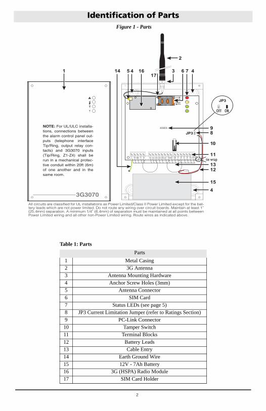
Figure 1 - Parts
Identification of Parts
Table 1: Parts
Parts
1 Metal Casing2 3G Antenna3 Antenna Mounting Hardware4 Anchor Screw Holes (3mm)5 Antenna Connector6 SIM Card7 Status LEDs (see page 5)8 JP3 Current Limitation Jumper (refer to Ratings Section)9 PC-Link Connector10 Tamper Switch11 Terminal Blocks12 Battery Leads13 Cable Entry14 Earth Ground Wire15 12V - 7Ah Battery16 3G (HSPA) Radio Module17 SIM Card Holder
1
LE LI- O1M O2 O3 O4 +OC AS M L1 L2 L3 L4 +12V-
LOCK
OPEN
44517
3
2
616
9
10
8
11
1312
15
14
4
12 13TAMPER
9PGM3
8PGM2
19 20+ DC IN -
11AUX+
16Z2
17Z3
15Z1
14COM
10PGM4
7PGM1
6COM
4T1
5R1
2TIP
3RNG
1 18Z4
JP3
JP3
tie wrap
OFF ON
All circuits are classified for UL installations as Power Limited/Class II Power Limited except for the bat-tery leads which are not power limited. Do not route any wiring over circuit boards. Maintain at least 1” (25.4mm) separation. A minimum 1/4” (6.4mm) of separation must be maintained at all points between Power Limited wiring and all other non-Power Limited wiring. Route wires as indicated above.
3G3070
NOTE: For UL/ULC installa-tions, connections between the alarm control panel out-puts (telephone interface Tip/Ring, output relay con-tacts) and 3G3070 inputs (Tip/Ring, Z1-Z4) shall be run in a mechanical protec-tive conduit within 20ft (6m) of one another and in the same room.

3
This equipment 3G3070 is fixed and shall be installed by Service Persons only (Service Person isdefined as a person having the appropriate technical training and experience necessary to beaware of hazards to which that person may be exposed in performing a task, and of measuresavailable to minimize the risks to that person or other persons). It shall be installed and usedwithin an environment that provides the pollution degree max 2, over voltages category II, innon-hazardous, indoor locations only. This manual shall be used with the Installation Manual ofthe relevant alarm control panel. All instructions specified within that manual must be observed.
DescriptionThis 3G3070 manages transmissions to a central station and can simulate the landline in the event of trouble (e.g., landline down) or even substitute the landline completely in areas where the 3G or 2G wireless service is provided and a landline is not available.The 3G3070 has the capability of communicating alarm signals via the 3G or 2G data network. This capability ensures a fast, reliable path to central stations equipped with a Sur-Gard System I / II / III / IV receiver. By connecting a 3G3070 to a control panel's standard PSTN interface, telephone-based Contact ID signals are decoded and seamlessly routed through the 3G or 2G network to any of the compatible receiver options.The performance of the 3G3070 depends greatly on wireless network coverage. Therefore, it should not be mounted without first performing placement tests to determine the best location for reception (minimum of one green LED ON). Optional antenna kits – GS15/25/50-ANT (15ft/4.6m, 25ft/7.6m or 50ft/15.2m) – are available.The 3G3070 requires enrollment with CONNECT 24 to operate. Dealer application forms and additional information on the CONNECT 24 Voice Response Unit (VRU) and web user interface can be found at www.connect24.com, or at the following telephone numbers:USA 1-888-251-7458 CANADA 1-888-955-5583For UL Residential Fire and Burglary installations, the 3G3070 is listed as a sole means of communication or as a back up when used in conjunction with a POTS line (dialer). For UL Residential Fire installations, when installed in the alternate enclosure for 3G3070RF, the 3G3070 has provisions for 24-hour standby power.For UL Commercial Burglary installations, the 3G3070 is listed as a sole means of communication (supervision window of 200s required at monitoring station) or as a back-up when used in conjunction with a POTS line (dialer).The 3G3070 shall be powered from any compatible listed control unit or compatible listed power supply that complies with the ratings specified on page 1. The power supply shall be listed for burglary applications and provide a minimum of 4 hours standby power capabilities. An example of a suitable listed compatible control unit is the DSC Model PC1864 with an AUX output rated 11.1 - 12.6VDC. An example of a suitable Listed power supply is DSC Model PC5204 with an AUX output rated 11.6 - 12.6VDC.For ULC Commercial Fire Monitoring installations the 3G3070 is listed as a passive communication system when used in conjunction with a POTS line (dialer). Fire alarms shall be sent simultaneously over both communication methods (wireless network and PSTN).For ULC Commercial Burglary installations the 3G3070 is listed as a passive communication system with communication line security level P2 when used as a back up in conjunction with a POTS line (dialer).For ULC Residential Fire and Burglary installations the 3G3070 is listed as a sole means communication or as a back up when used in conjunction with a POTS line (dialer).ATTENTION: The 3G3070 is equipped with a current limiter that limits current demand on the12VDC power input to 120mA. The current limiter is enabled by default (see Part #8 in 'Identifica-tion of Parts’ on page 3) with JP3 in the OFF position. The current limiter can be disabled(bypassed) with JP3 in the ON position. When the 3G3070 12VDC power input is supplied by theAlarm Panel Aux+ output, DSC recommends that the current limiter be active to limit the demandfrom the panel. If the alarm panel is intended to supply all of the current demand, you mustensure that the panel can supply 500mA and that the current limiter is disabled. When the 3G3070is transmitting, the current demand exceeds 120mA (500mA). With the current limiter in place,the additional current demand is supplied by the 3G3070 battery.NOTE: With the current limiter active, there is a risk of discharging the 3G3070 battery whentransmission frequency is high. The back up battery must always be connected to the device whenthe current limiter is enabled.If power to the 3G3070 is supplied by an external power supply (recommended 13.8 VDC, 0.7A), the current limiter must be disabled to allow the full current demand to be supplied. In this configuration the 3G3070 battery is not required.
4
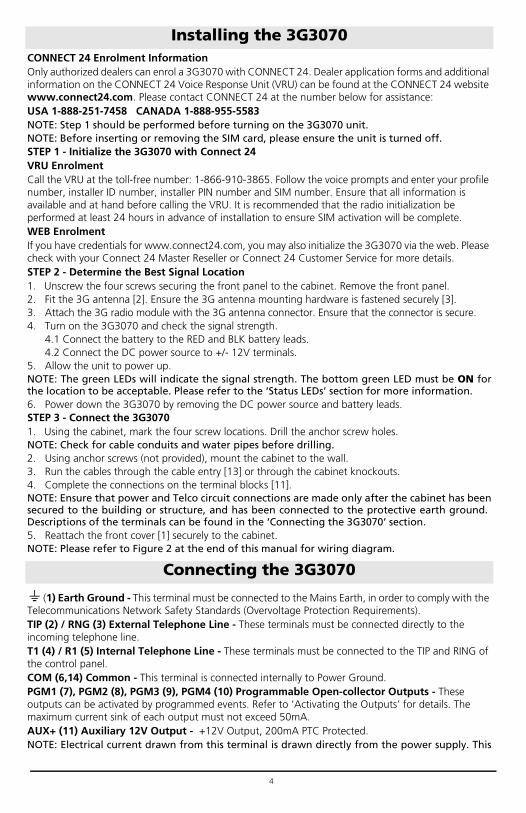
CONNECT 24 Enrolment InformationOnly authorized dealers can enrol a 3G3070 with CONNECT 24. Dealer application forms and additional information on the CONNECT 24 Voice Response Unit (VRU) can be found at the CONNECT 24 website www.connect24.com. Please contact CONNECT 24 at the number below for assistance:USA 1-888-251-7458 CANADA 1-888-955-5583NOTE: Step 1 should be performed before turning on the 3G3070 unit.NOTE: Before inserting or removing the SIM card, please ensure the unit is turned off.STEP 1 - Initialize the 3G3070 with Connect 24VRU EnrolmentCall the VRU at the toll-free number: 1-866-910-3865. Follow the voice prompts and enter your profile number, installer ID number, installer PIN number and SIM number. Ensure that all information is available and at hand before calling the VRU. It is recommended that the radio initialization be performed at least 24 hours in advance of installation to ensure SIM activation will be complete.WEB EnrolmentIf you have credentials for www.connect24.com, you may also initialize the 3G3070 via the web. Please check with your Connect 24 Master Reseller or Connect 24 Customer Service for more details.STEP 2 - Determine the Best Signal Location1. Unscrew the four screws securing the front panel to the cabinet. Remove the front panel.2. Fit the 3G antenna [2]. Ensure the 3G antenna mounting hardware is fastened securely [3].3. Attach the 3G radio module with the 3G antenna connector. Ensure that the connector is secure.4. Turn on the 3G3070 and check the signal strength.
4.1 Connect the battery to the RED and BLK battery leads.4.2 Connect the DC power source to +/- 12V terminals.
5. Allow the unit to power up.NOTE: The green LEDs will indicate the signal strength. The bottom green LED must be ON forthe location to be acceptable. Please refer to the ‘Status LEDs’ section for more information.6. Power down the 3G3070 by removing the DC power source and battery leads. STEP 3 - Connect the 3G3070 1. Using the cabinet, mark the four screw locations. Drill the anchor screw holes. NOTE: Check for cable conduits and water pipes before drilling.2. Using anchor screws (not provided), mount the cabinet to the wall.3. Run the cables through the cable entry [13] or through the cabinet knockouts.4. Complete the connections on the terminal blocks [11]. NOTE: Ensure that power and Telco circuit connections are made only after the cabinet has beensecured to the building or structure, and has been connected to the protective earth ground. Descriptions of the terminals can be found in the ‘Connecting the 3G3070’ section.5. Reattach the front cover [1] securely to the cabinet.NOTE: Please refer to Figure 2 at the end of this manual for wiring diagram.
(1) Earth Ground - This terminal must be connected to the Mains Earth, in order to comply with the Telecommunications Network Safety Standards (Overvoltage Protection Requirements).TIP (2) / RNG (3) External Telephone Line - These terminals must be connected directly to the incoming telephone line.T1 (4) / R1 (5) Internal Telephone Line - These terminals must be connected to the TIP and RING of the control panel.COM (6,14) Common - This terminal is connected internally to Power Ground.PGM1 (7), PGM2 (8), PGM3 (9), PGM4 (10) Programmable Open-collector Outputs - These outputs can be activated by programmed events. Refer to ‘Activating the Outputs’ for details. The maximum current sink of each output must not exceed 50mA. AUX+ (11) Auxiliary 12V Output - +12V Output, 200mA PTC Protected. NOTE: Electrical current drawn from this terminal is drawn directly from the power supply. This
Installing the 3G3070
Connecting the 3G3070
5
must be added to the 3G3070 current when determining the total draw on the host panel orpower supply. Jumper JP3 does not limit the electrical current available on this output.Tamper (12-13) - These terminals are connected in series to the Tamper switch [10]. They will close when the cabinet is properly closed, and will open when the front cover is removed.Z1-Z4 (15-16-17-18) Programmable Inputs - These terminals can be set up to trigger events. Refer to ‘Inputs’ for details.12V (19), COM (20) Device Power Supply - hese terminals must be connected to a rated power supply. Once the connections are completed, connect the battery leads (Red and Black wires, [12] in Figure 1) to a 12V, 7Ah battery.Jumper JP3
JP3 ON - Full power, including standby capacity, comes from the host panel or external power supply. Supply must be capable of up to 700mA. The 3G3070 battery must not be connected.JP3 OFF - Current limiting mode, the host panel or external supply provides standby current. Supply must be capable of 120mA plus any current drawn from AUX+ terminal. 3G3070 battery must be installed for proper operation.
NOTE: The power supply must have a minimum voltage of 13.5V to ensure a sufficient batterycharge. An example of a suitable power supply is the DSC Model ADP1310-NA with DC outputrated 13.8 VDC, 1Amp. This is to be used in conjunction with a 12V/7Ah rated battery for UL/ULClisted residential installations.NOTE: This mode of operation must not be used for ULC Listed Fire Monitoring installations.NOTE: When disposing of batteries, follow the instructions and precautions printed on the bat-teries, and contact your municipal offices for information on the disposal of used batteries.
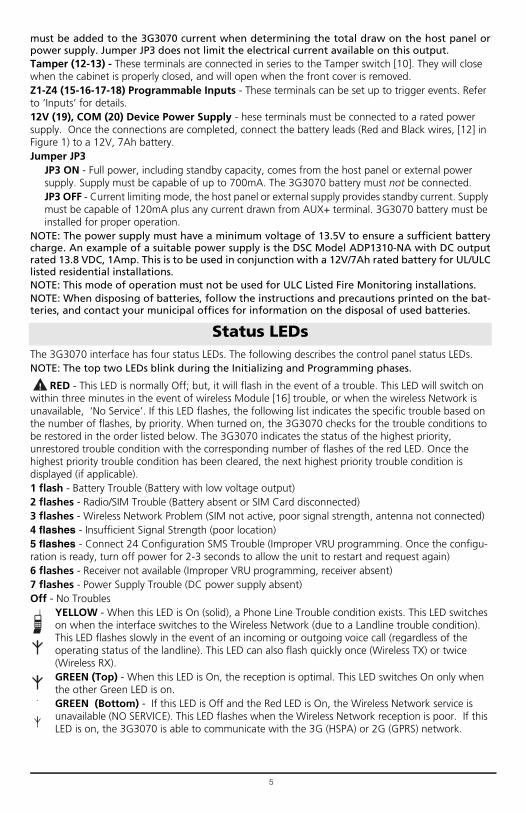
The 3G3070 interface has four status LEDs. The following describes the control panel status LEDs.NOTE: The top two LEDs blink during the Initializing and Programming phases.
RED - This LED is normally Off; but, it will flash in the event of a trouble. This LED will switch on within three minutes in the event of wireless Module [16] trouble, or when the wireless Network is unavailable, ‘No Service’. If this LED flashes, the following list indicates the specific trouble based on the number of flashes, by priority. When turned on, the 3G3070 checks for the trouble conditions to be restored in the order listed below. The 3G3070 indicates the status of the highest priority, unrestored trouble condition with the corresponding number of flashes of the red LED. Once the highest priority trouble condition has been cleared, the next highest priority trouble condition is displayed (if applicable).1 flash - Battery Trouble (Battery with low voltage output)2 flashes - Radio/SIM Trouble (Battery absent or SIM Card disconnected)3 flashes - Wireless Network Problem (SIM not active, poor signal strength, antenna not connected)4 flashes - Insufficient Signal Strength (poor location)5 flashes - Connect 24 Configuration SMS Trouble (Improper VRU programming. Once the configu-ration is ready, turn off power for 2-3 seconds to allow the unit to restart and request again)6 flashes - Receiver not available (Improper VRU programming, receiver absent)7 flashes - Power Supply Trouble (DC power supply absent)Off - No Troubles
YELLOW - When this LED is On (solid), a Phone Line Trouble condition exists. This LED switches on when the interface switches to the Wireless Network (due to a Landline trouble condition). This LED flashes slowly in the event of an incoming or outgoing voice call (regardless of the operating status of the landline). This LED can also flash quickly once (Wireless TX) or twice (Wireless RX).GREEN (Top) - When this LED is On, the reception is optimal. This LED switches On only when the other Green LED is on.GREEN (Bottom) - If this LED is Off and the Red LED is On, the Wireless Network service is unavailable (NO SERVICE). This LED flashes when the Wireless Network reception is poor. If this LED is on, the 3G3070 is able to communicate with the 3G (HSPA) or 2G (GPRS) network.
Status LEDs

6
Simulated Landline ModeThe simulated landline provides the alarm control panel (with dialer interface) with a back up line in the event of PSTN line trouble. If the voltage on the landline terminals (TIP/RNG) drops below 2.8V for a period of between 10 seconds and 45 seconds - depending on the device connected to the T1/R1 terminals- the 3G3070 switches the connected telephone device to the wireless network. After waiting between 30 and 40 seconds, it checks the landline for one of the following:
• If the landline has been restored, the 3G3070 switches the connected device back to the landline, OR
• If the landline is still down, the 3G3070 continues the simulation until the landline is restored. The 3G3070 will not switch during ongoing calls.
NOTE: When the landline is down, the 3G3070 provides a dial tone to any device connected toT1 and R1, including any telephones on the premises. The phones on the premises will not, how-ever, be able to dial out over the 3G3070.
Panel Transmission Monitoring (PTM)The 3G3070 can also monitor the panel’s attempt to communicate with the central station. If it determines that the panel is having difficulty, it switches the line to the wireless network. This feature is only active when the 3G3070 is configured as a back up communicator. This feature is in addition to the regular line voltage detection.The 3G3070 monitors the phone line for four consecutive failed attempts within a 12-minute window. A failed attempt is assumed to have occurred when a line seizure takes place during dialing (either the alarm panel or the customer telephone), but no 1400Hz tone (or Contact Kiss-off) is sent from the receiver.Once the conditions for a failed attempt are met, the 3G3070 connects the panel to the wireless network to communicate the events. When the 3G3070 switches the line it stays in this mode until the panel hangs up. On the next event the 3G3070 restarts the error detection sequence before switching.The 3G3070 performs this sequence on any phone number that is detected on the line. Specific central station phone numbers can be programmed into the 3G3070 if desired. Up to four, 20-digit numbers can be added to your profile at Connect 24. If programmed, the 3G3070 will only look for Contact ID Kiss-off after these numbers are dialed. A Telephone Line Monitoring trouble (PGM output activation and/or reporting code if applicable) is also activated and/or transmitted when the PTM is activated. A restoral is sent at the end of the call.
Wireless Communications Sequence• When an alarm is triggered, the control panel goes off-hook.• The 3G3070 asserts a dial tone.• The Control panel dials the number of the central station. Ensure that the alarm panel inserts a
minimum one second pause, or has Dial Tone Search enabled before dialing the number.• The 3G3070 detects the DTMF dialing and stops dial tone.
NOTE: The 3G3070 is unable to decode pulse dialing.• The 3G3070 sends the required Contact ID dual-tone handshake to the panel.• After receiving the handshake, the control panel transmits an alarm message in Contact ID format.• The 3G3070 decodes and transforms the Contact ID digits into an IP packet and sends it to the
central station receiver over the wireless network.• The central station receiver acknowledges the alarm and sends a command to the 3G3070 to gen-
erate the corresponding 1400Hz Kiss-off signal for a minimum of 800msec.After the 3G3070 generates a Kiss-off signal, it sends the next alarm or, if no further alarms need to be sent, the control panel goes on-hook.
InputsThe 3G3070 has four inputs that can be used to trigger specific communications. These events will transmit using Contact ID format with Inputs 1-4 reporting as [991] to [994] respectively. Default settings are:INPUT 1- FIRE INPUT 3 - BURGLARYINPUT 2 - PANIC ALARM INPUT 4 - SYSTEM TROUBLEThese inputs are normally open and will activate when a short condition is detected between the terminal and the COM. Refer to the 3G3070 Wiring Diagram (Figure 2) at the back of this manual.NOTE: These inputs communicate using Contact ID format.
Operating Principles
7
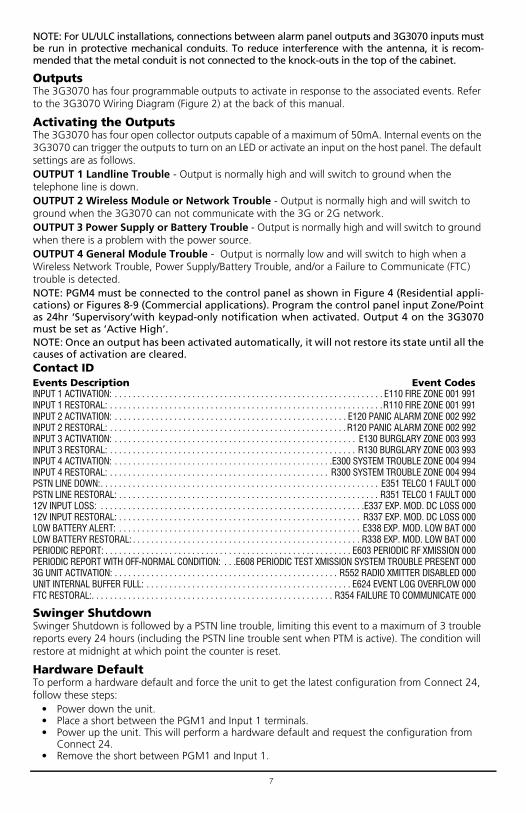
NOTE: For UL/ULC installations, connections between alarm panel outputs and 3G3070 inputs mustbe run in protective mechanical conduits. To reduce interference with the antenna, it is recom-mended that the metal conduit is not connected to the knock-outs in the top of the cabinet.
OutputsThe 3G3070 has four programmable outputs to activate in response to the associated events. Refer to the 3G3070 Wiring Diagram (Figure 2) at the back of this manual.
Activating the OutputsThe 3G3070 has four open collector outputs capable of a maximum of 50mA. Internal events on the 3G3070 can trigger the outputs to turn on an LED or activate an input on the host panel. The default settings are as follows.OUTPUT 1 Landline Trouble - Output is normally high and will switch to ground when the telephone line is down.OUTPUT 2 Wireless Module or Network Trouble - Output is normally high and will switch to ground when the 3G3070 can not communicate with the 3G or 2G network.OUTPUT 3 Power Supply or Battery Trouble - Output is normally high and will switch to ground when there is a problem with the power source.OUTPUT 4 General Module Trouble - Output is normally low and will switch to high when a Wireless Network Trouble, Power Supply/Battery Trouble, and/or a Failure to Communicate (FTC) trouble is detected.NOTE: PGM4 must be connected to the control panel as shown in Figure 4 (Residential appli-cations) or Figures 8-9 (Commercial applications). Program the control panel input Zone/Pointas 24hr ‘Supervisory’with keypad-only notification when activated. Output 4 on the 3G3070must be set as ‘Active High’.NOTE: Once an output has been activated automatically, it will not restore its state until all thecauses of activation are cleared.Contact IDEvents Description Event CodesINPUT 1 ACTIVATION: . . . . . . . . . . . . . . . . . . . . . . . . . . . . . . . . . . . . . . . . . . . . . . . . . . . . . . . . . . . E110 FIRE ZONE 001 991INPUT 1 RESTORAL: . . . . . . . . . . . . . . . . . . . . . . . . . . . . . . . . . . . . . . . . . . . . . . . . . . . . . . . . . . . .R110 FIRE ZONE 001 991INPUT 2 ACTIVATION: . . . . . . . . . . . . . . . . . . . . . . . . . . . . . . . . . . . . . . . . . . . . . . . . . . . E120 PANIC ALARM ZONE 002 992INPUT 2 RESTORAL: . . . . . . . . . . . . . . . . . . . . . . . . . . . . . . . . . . . . . . . . . . . . . . . . . . . . R120 PANIC ALARM ZONE 002 992INPUT 3 ACTIVATION: . . . . . . . . . . . . . . . . . . . . . . . . . . . . . . . . . . . . . . . . . . . . . . . . . . . . . E130 BURGLARY ZONE 003 993INPUT 3 RESTORAL: . . . . . . . . . . . . . . . . . . . . . . . . . . . . . . . . . . . . . . . . . . . . . . . . . . . . . . R130 BURGLARY ZONE 003 993INPUT 4 ACTIVATION: . . . . . . . . . . . . . . . . . . . . . . . . . . . . . . . . . . . . . . . . . . . . . . . .E300 SYSTEM TROUBLE ZONE 004 994INPUT 4 RESTORAL: . . . . . . . . . . . . . . . . . . . . . . . . . . . . . . . . . . . . . . . . . . . . . . . . R300 SYSTEM TROUBLE ZONE 004 994PSTN LINE DOWN:. . . . . . . . . . . . . . . . . . . . . . . . . . . . . . . . . . . . . . . . . . . . . . . . . . . . . . . . . . . . . E351 TELCO 1 FAULT 000PSTN LINE RESTORAL: . . . . . . . . . . . . . . . . . . . . . . . . . . . . . . . . . . . . . . . . . . . . . . . . . . . . . . . . . R351 TELCO 1 FAULT 00012V INPUT LOSS: . . . . . . . . . . . . . . . . . . . . . . . . . . . . . . . . . . . . . . . . . . . . . . . . . . . . . . . . . .E337 EXP. MOD. DC LOSS 00012V INPUT RESTORAL: . . . . . . . . . . . . . . . . . . . . . . . . . . . . . . . . . . . . . . . . . . . . . . . . . . . . . R337 EXP. MOD. DC LOSS 000LOW BATTERY ALERT: . . . . . . . . . . . . . . . . . . . . . . . . . . . . . . . . . . . . . . . . . . . . . . . . . . . . . E338 EXP. MOD. LOW BAT 000LOW BATTERY RESTORAL: . . . . . . . . . . . . . . . . . . . . . . . . . . . . . . . . . . . . . . . . . . . . . . . . . . R338 EXP. MOD. LOW BAT 000PERIODIC REPORT: . . . . . . . . . . . . . . . . . . . . . . . . . . . . . . . . . . . . . . . . . . . . . . . . . . . . . . E603 PERIODIC RF XMISSION 000PERIODIC REPORT WITH OFF-NORMAL CONDITION: . . .E608 PERIODIC TEST XMISSION SYSTEM TROUBLE PRESENT 0003G UNIT ACTIVATION: . . . . . . . . . . . . . . . . . . . . . . . . . . . . . . . . . . . . . . . . . . . . . . . . . R552 RADIO XMITTER DISABLED 000UNIT INTERNAL BUFFER FULL: . . . . . . . . . . . . . . . . . . . . . . . . . . . . . . . . . . . . . . . . . . . . . E624 EVENT LOG OVERFLOW 000FTC RESTORAL:. . . . . . . . . . . . . . . . . . . . . . . . . . . . . . . . . . . . . . . . . . . . . . . . . . . . . R354 FAILURE TO COMMUNICATE 000
Swinger ShutdownSwinger Shutdown is followed by a PSTN line trouble, limiting this event to a maximum of 3 trouble reports every 24 hours (including the PSTN line trouble sent when PTM is active). The condition will restore at midnight at which point the counter is reset.
Hardware DefaultTo perform a hardware default and force the unit to get the latest configuration from Connect 24, follow these steps:
• Power down the unit.• Place a short between the PGM1 and Input 1 terminals.• Power up the unit. This will perform a hardware default and request the configuration from
Connect 24.• Remove the short between PGM1 and Input 1.

8
NOTE: If the unit has previously received programming from Connect 24, a hardware default isrequired to initiate the download of the latest configuration from Connect 24. Failure to do sowill result in the unit transmitting with the previously programmed configuration.NOTE: A Hardware default must be performed when the SIM card is being swapped.
Low Power Radio ShutdownWhen the battery voltage reaches the low battery threshold of 10.5V, the unit turns off the radio to prevent unnecessary network registrations. In this state, the unit does not communicate any events.Radio shutdown is indicated by the LEDs as follows:
• for 1 second -- red is on, yellow is off, green 1 is off, and green 2 is off.• for 1 second -- red is off, yellow is on, green 1 is on, and green 2 is on.
This LED sequence will continue to be displayed until the low battery voltage is restored and the radio enabled again.
The inputs, outputs, and other features can be remotely programmed through Connect 24 for fast and convenient installation using the internet.NOTE: This programming option has not been investigated by UL.
Powering up the 3G3070 – when powering up the 3G3070, always connect the battery first before connecting primary DC power from the control panel or transformer.Wiring Primary – R-1/T-1 of 3G3070 to RING/TIP of control panel, DC power from control panel or DC transformer to DC input, backup battery if JP3 OFF.Wiring Backup – Incoming line to RING/TIP on 3G3070, R-1/T-1 of 3G3070 to RING/TIP of control panel, R-1/T-1 of control panel to house phones, DC power from control panel or DC transformer to DC input, backup battery if JP3 OFF.Testing Communications – when the 3G3070 transmits a signal for the control panel, or for an internal transmission, the YELLOW light will flash one time when the signal is transmitted and two times when it gets a kiss-off.SIM – the SIM should be activated at least 24 hours prior to installation. The 3G3070 will show signal strength with an inactive SIM, however it will display the signal strength of any available wireless network. The SIM must be active to ensure the signal strength displayed is that of the wireless network provider for which the SIM belongs to.Panel Programming – the control panel should be programmed to communicate Contact ID exactly the same way it would be programmed to communicate Contact ID over the telephone line.
Connect 24 Remote Programming
Troubleshooting Guide
Green Light Status
What it means: Signal Strength Status
Both Green Lights ON Excellent Signal Strength
• Unit can be installed in the current mounting location
One Green Light ON Good Signal Strength • Unit can be installed in the current mounting location
Bottom Green Light FLASHING
Poor Signal Strength • Ensure the antenna cable is plugged securely into the radio connector
• If the SIM is active, connect a battery to the unit and test various locations for good/excel-lent signal strength
• Connect an antenna extension kit (GS-15ANT, GS-25ANT or GS-50ANT)
9
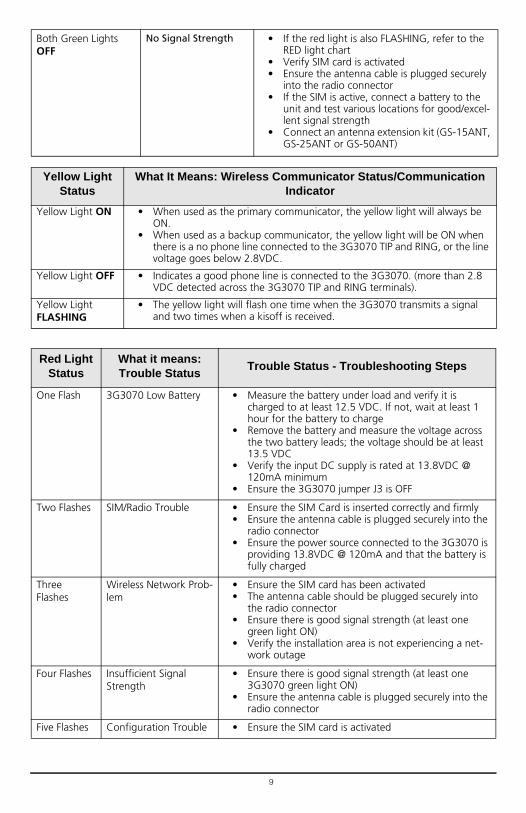
Both Green Lights OFF
No Signal Strength • If the red light is also FLASHING, refer to the RED light chart
• Verify SIM card is activated• Ensure the antenna cable is plugged securely
into the radio connector• If the SIM is active, connect a battery to the
unit and test various locations for good/excel-lent signal strength
• Connect an antenna extension kit (GS-15ANT, GS-25ANT or GS-50ANT)
Yellow Light Status
What It Means: Wireless Communicator Status/Communication Indicator
Yellow Light ON • When used as the primary communicator, the yellow light will always be ON.
• When used as a backup communicator, the yellow light will be ON when there is a no phone line connected to the 3G3070 TIP and RING, or the line voltage goes below 2.8VDC.
Yellow Light OFF • Indicates a good phone line is connected to the 3G3070. (more than 2.8 VDC detected across the 3G3070 TIP and RING terminals).
Yellow Light FLASHING
• The yellow light will flash one time when the 3G3070 transmits a signal and two times when a kisoff is received.
Red Light Status
What it means:Trouble Status
Trouble Status - Troubleshooting Steps
One Flash 3G3070 Low Battery • Measure the battery under load and verify it is charged to at least 12.5 VDC. If not, wait at least 1 hour for the battery to charge
• Remove the battery and measure the voltage across the two battery leads; the voltage should be at least 13.5 VDC
• Verify the input DC supply is rated at 13.8VDC @ 120mA minimum
• Ensure the 3G3070 jumper J3 is OFF
Two Flashes SIM/Radio Trouble • Ensure the SIM Card is inserted correctly and firmly• Ensure the antenna cable is plugged securely into the
radio connector• Ensure the power source connected to the 3G3070 is
providing 13.8VDC @ 120mA and that the battery is fully charged
Three Flashes
Wireless Network Prob-lem
• Ensure the SIM card has been activated• The antenna cable should be plugged securely into
the radio connector• Ensure there is good signal strength (at least one
green light ON)• Verify the installation area is not experiencing a net-
work outage
Four Flashes Insufficient Signal Strength
• Ensure there is good signal strength (at least one 3G3070 green light ON)
• Ensure the antenna cable is plugged securely into the radio connector
Five Flashes Configuration Trouble • Ensure the SIM card is activated

10
Six Flashes Receiver Not Available • Contact the monitoring station to verify that the 3G3070 programming is correct (port, IP address, DNIS)
• Contact your central station to verify they are not experiencing any receiver issues
Seven Flashes
DC Supply Trouble • Ensure the power source connected to the 3G3070 is providing 13.8VDC @ 120mA
11
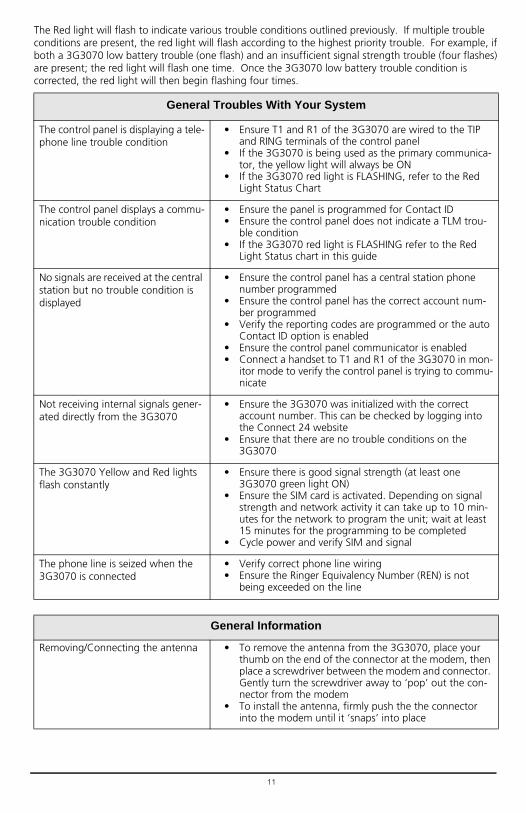
The Red light will flash to indicate various trouble conditions outlined previously. If multiple trouble conditions are present, the red light will flash according to the highest priority trouble. For example, if both a 3G3070 low battery trouble (one flash) and an insufficient signal strength trouble (four flashes) are present; the red light will flash one time. Once the 3G3070 low battery trouble condition is corrected, the red light will then begin flashing four times.
General Troubles With Your System
The control panel is displaying a tele-phone line trouble condition
• Ensure T1 and R1 of the 3G3070 are wired to the TIP and RING terminals of the control panel
• If the 3G3070 is being used as the primary communica-tor, the yellow light will always be ON
• If the 3G3070 red light is FLASHING, refer to the Red Light Status Chart
The control panel displays a commu-nication trouble condition
• Ensure the panel is programmed for Contact ID• Ensure the control panel does not indicate a TLM trou-
ble condition• If the 3G3070 red light is FLASHING refer to the Red
Light Status chart in this guide
No signals are received at the central station but no trouble condition is displayed
• Ensure the control panel has a central station phone number programmed
• Ensure the control panel has the correct account num-ber programmed
• Verify the reporting codes are programmed or the auto Contact ID option is enabled
• Ensure the control panel communicator is enabled• Connect a handset to T1 and R1 of the 3G3070 in mon-
itor mode to verify the control panel is trying to commu-nicate
Not receiving internal signals gener-ated directly from the 3G3070
• Ensure the 3G3070 was initialized with the correct account number. This can be checked by logging into the Connect 24 website
• Ensure that there are no trouble conditions on the 3G3070
The 3G3070 Yellow and Red lights flash constantly
• Ensure there is good signal strength (at least one 3G3070 green light ON)
• Ensure the SIM card is activated. Depending on signal strength and network activity it can take up to 10 min-utes for the network to program the unit; wait at least 15 minutes for the programming to be completed
• Cycle power and verify SIM and signal
The phone line is seized when the 3G3070 is connected
• Verify correct phone line wiring• Ensure the Ringer Equivalency Number (REN) is not
being exceeded on the line
General Information
Removing/Connecting the antenna • To remove the antenna from the 3G3070, place your thumb on the end of the connector at the modem, then place a screwdriver between the modem and connector. Gently turn the screwdriver away to ‘pop’ out the con-nector from the modem
• To install the antenna, firmly push the the connector into the modem until it ‘snaps’ into place
12
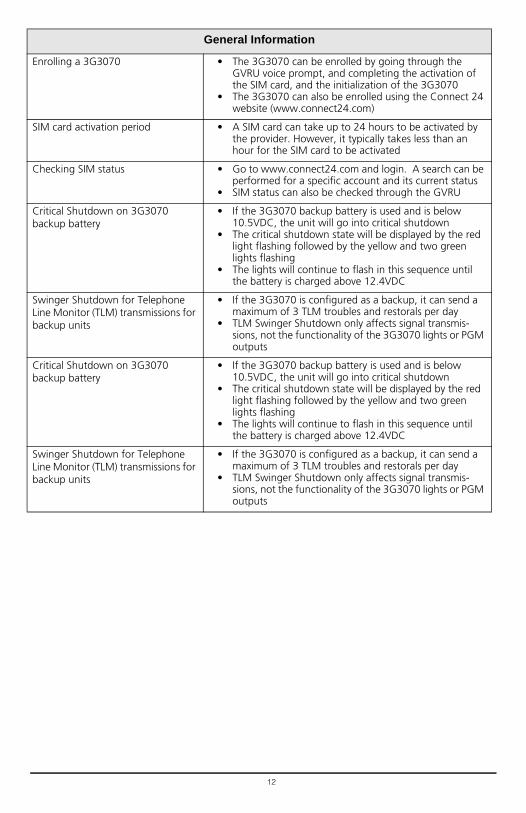
Enrolling a 3G3070 • The 3G3070 can be enrolled by going through the GVRU voice prompt, and completing the activation of the SIM card, and the initialization of the 3G3070
• The 3G3070 can also be enrolled using the Connect 24 website (www.connect24.com)
SIM card activation period • A SIM card can take up to 24 hours to be activated by the provider. However, it typically takes less than an hour for the SIM card to be activated
Checking SIM status • Go to www.connect24.com and login. A search can be performed for a specific account and its current status
• SIM status can also be checked through the GVRU
Critical Shutdown on 3G3070 backup battery
• If the 3G3070 backup battery is used and is below 10.5VDC, the unit will go into critical shutdown
• The critical shutdown state will be displayed by the red light flashing followed by the yellow and two green lights flashing
• The lights will continue to flash in this sequence until the battery is charged above 12.4VDC
Swinger Shutdown for Telephone Line Monitor (TLM) transmissions for backup units
• If the 3G3070 is configured as a backup, it can send a maximum of 3 TLM troubles and restorals per day
• TLM Swinger Shutdown only affects signal transmis-sions, not the functionality of the 3G3070 lights or PGM outputs
General Information

13
Figure 2 - Wiring Diagram
3G3070 Wiring Diagrams
54
12
36
78
910
1114
1516
1718
1920
LELI
O1O2
O3O4
+OC
1312AS
L1L2
L3L4
12V
1K5
This
Con
nect
ion
isne
cess
ary
T I PT I P
R I N GR I N G
3G30
7012
1
3TA
MPE
R9
PGM3
8PG
M219
2
0+
DC IN
-11
AUX+
16 Z217 Z3
15 Z114 CO
M10 PGM4
7PG
M16 COM
4 T15 R1
2 TIP
3 RNG
118 Z4
RJ-4
5
BATT
ERY
Seale
d Re
char
geab
le12
V / 1
.2Ah
Typi
cal b
atte
ry ch
arge
: 30-
50 m
ARe
com
men
ded
Mod
el: 1
2V/1
.2Ah
or
12V/
7Ah
(for
ord
er co
de 3
G307
0 on
ly)
Batte
ry n
ot re
quire
dif
JP3
is ON
9-14
VDC/
*70
0mA
(max
)
Tam
per
Outp
ut
Eart
h-gr
ound
Grou
nd w
irefr
om b
uild
ing
elec
trica
l ins
talla
tion
Inpu
ts to
be
conn
ecte
dto
dry
cont
act o
utpu
tsfr
om a
larm
cont
rol p
anel
}
GRO
UN
DCO
NN
ECTI
ON
Tigh
ten
nut t
o br
eak
pain
t &m
ake
good
conn
ectio
n to
th
e ca
bine
t.Nu
t
Nut
Bolt
Lock
was
her
Lock
was
her
Star
was
her
Cabi
net
Alar
m C
ontr
ol P
anel
with
Dial
ler I
nter
face
(Sup
port
s Con
tact
ID fo
rmat
)
Pane
l Aux
Pow
eror
Ext
erna
l Pow
erSu
pply
(13.
8VDC
re
quire
d fo
r nor
mal
,lo
ng-t
erm
ope
ratio
n)
Tele
phon
e Li
neCo
nnec
tion
Supe
rvisi
onRe
lay
RM1-
UL In
stal
latio
nsRM
1C-U
LC In
stal
latio
ns
WAR
NING
: Inc
orre
ct co
nnec
tions
may
resu
lt in
PTC
failu
re o
r im
prop
er o
pera
tion.
Insp
ect w
iring
and
ens
ure
conn
ectio
ns a
re co
rrec
t bef
ore
turn
ing
on.
Conn
ect r
elay
cont
acts
toa
zone
inpu
t on
the
alar
mco
ntro
l pan
el fo
r 3G3
070
trou
bles
supe
rvisi
on
(24h
r-ty
pe z
one)
Optio
nal
use
of P
GMou
tput
(See
Prog
ram
min
g)
WAR
NING
!HI
GH V
OLTA
GE. D
ISCO
NNEC
T AC
POW
ER &
TEL
EPHO
NE L
INES
PRIO
R TO
SER
VICI
NG
All c
ircui
ts a
re cl
assif
ied
for U
L in
stal
latio
ns a
s Pow
er L
imite
d/Cl
ass I
I Pow
er L
imite
d ex
cept
for t
he b
atte
ry le
ads w
hich
are
not
Pow
er L
imite
d. D
o no
t rou
te a
ny w
iring
ov
er ci
rcui
t boa
rds.
Mai
ntai
n at
leas
t 1”
(25.
4mm
) sep
arat
ion.
A m
inim
um 1
/4”
(6.4
mm
) sep
arat
ion
mus
t be
mai
ntai
ned
at a
ll po
ints
bet
ween
Pow
er L
imite
d wi
ring
and
all o
ther
Non
-Pow
er L
imite
d wi
ring.
Rou
te w
ires a
s ind
icate
d in
the
diag
ram
.NO
TE: F
or U
LC C
omm
ercia
l Fire
and
Bur
glar
y In
stal
latio
n re
quire
men
ts p
leas
e re
fer t
o Fi
gure
s 5, 6
, 7 &
8 a
nd to
the
ULC
Inst
alla
tion
Guid
e P/
N 29
0021
57R0
09.
(Use
No.
26
AWG
wire
s for
the
conn
ectio
n to
PST
N)*R
efer
to Ju
mpe
r 3 se
ctio
n
for c
urre
nt ra
ting
For
ULC
Fire
Mon
itorin
g in
stal
latio
ns f
ire a
larm
sig
nals
shal
l be
sen
t sim
ulta
neou
sly o
ver
POTS
line
(us
ing
the
dial
ler)
and
ove
r th
e wi
rele
ss
netw
ork
(usin
g 3G
3070
). Co
nnec
t ala
rm o
utpu
t fro
m co
ntro
l pan
el (P
GM)
to th
e in
put o
n th
e 3G
3070
that
is p
rogr
amm
ed a
s a F
ire A
larm
Inpu
t.
Exam
ples
of C
ontr
ol U
nits
/Sub
scrib
ers U
nits
or P
ower
Sup
plie
s com
patib
lem
odel
s: D
SC P
C186
4, P
C183
2, P
C161
6, P
C520
4, e
tc.
DG009655
14
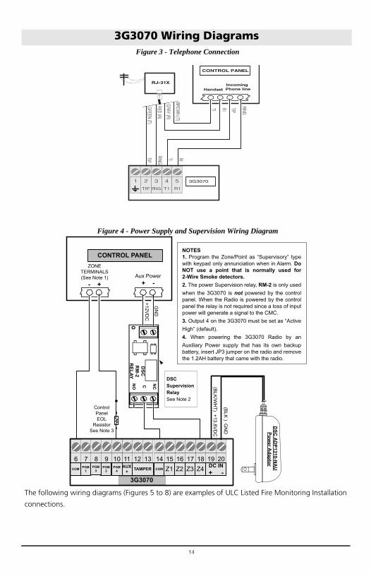
Figure 3 - Telephone Connection
Figure 4 - Power Supply and Supervision Wiring Diagram
The following wiring diagrams (Figures 5 to 8) are examples of ULC Listed Fire Monitoring Installation
connections.
3G3070 Wiring Diagrams
RED (R)
GREEN (T)
GRAY (R)
BROWN (T)
RJ-31X
RING
TIP
CONTROL PANEL
IncomingPhone lineHandset
RITI
TI RITIP
RING
4321 5 3G3070
TIP T1 R1RNG
(BLK
/WH
T) +13.8VD
C
(BLK
) GN
D
ControlPanel EOL
ResistorSee Note 3
DSC
RM
-2 R
ELAY
NCCNO
ZONE TERMINALS(See Note 1)
- +
+12VD
C
GN
D
CONTROL PANEL
Aux Power+ -
DSC Supervision RelaySee Note 2
1918171614 201512111097 138619Z4Z3Z2COM 20Z112AUX
+PGM
3PGM
1 13PGM4COM TAMPER
3G3070
PGM3
DC IN+ -
DSC
AD
P1310-NA
U Pow
er Adaptor
NOTES1. Program the Zone/Point as “Supervisory” type with keypad only annunciation when in Alarm. Do NOT use a point that is normally used for 2-Wire Smoke detectors.2. The power Supervision relay, RM-2 is only used when the 3G3070 is not powered by the control panel. When the Radio is powered by the control panel the relay is not required since a loss of input power will generate a signal to the CMC. 3. Output 4 on the 3G3070 must be set as “Active High” (default).4. When powering the 3G3070 Radio by an Auxiliary Power supply that has its own backup battery, insert JP3 jumper on the radio and remove the 1.2AH battery that came with the radio.

15
Figure 5 - Fire Alarm Control Unit and 3G Transmitter
Figure 6 - DSC Subscribers’ Unit Fire and 3G Transmitter Mounted in the Same Room
3G3070 Wiring Diagrams
Wiring Diagram for Fire Alarm Control Unit (with dialler) and 3G (HSPA/2G (GPRS) Transmitter (Passive Communication System)
AUX Power
(12V/700mA)
RM1C ULC
Relay
Fire Alarm
Control Unit
TIP/RING
Zone Input
Outputs
Fire
Trouble
3G Wireless
Transmitter
3G3070
T1/R1
TIP/RING
Zone PGM4
Inputs Output
3G3070 cabinet
3G (HSPA) or
2G (GPRS)
AC Input
NOTES:
- Power for 3G3070 shall be provided from Fire Alarm Control Unit or separately Listed power supply rated for the application, 12V/700mA (Jumper JP3 shall be set to on for Fire Monitoring).
- All wiring connections must be run in a protective conduit.
- For local supervision of the wireless transmitter connect PGM output from 3G3070 to one zone input on the Fire Alarm Control Unit.
- Dry Contact Trouble output from ULC Listed Fire Alarm Control Unit must be connected to zone input on the 3G3070 for supervision of Tip/Ring connection.
- Fire Alarms must be sent over both communication
channels. Fire output from Fire Alarm Control Unit
must be connected to the Input 1 on the 3G3070.
- 24h Test Transmission must be enabled on the dialler and on the 3G3070.
PSTN
Wiring Diagram for DSC Subscribers’ Unit Fire and 3G Transmitter
(Passive Communication System)
Fire Alarm
Control Unit
Outputs
Fire
Supervisory
Trouble
DSC
Subscribers’
Unit Fire
Zone
Inputs TIP
TIP RING
PGM1
DSC Keypad
LCD4501
PK55XX
3G Wireless
Transmitter
3G3070
T1/R1
TIP/RING
Zone
Input PGM4
AUX Power
12V/700mA
RM1C ULC
Relay
PC5003C
PC4050CR
cabinet
3G (HSPA)/2G (GPRS)
PSTN
AC Input
AC Input
NOTES:
- Power for 3G3070 must be provided from Fire Alarm Control Unit or separately listed power supply rated for the application (12V/700mA)
(Jumper JP3 shall be on for Fire Monitoring).
- All wiring connections must be run in a protective conduit.
- Phone Line Monitoring (TLM) must be enabled.
- Connect PGM4 output from 3G3070 (Trouble Conditions) to a zone input on the Subscriber Unit for supervision of the GSM Transmitter.
- 24hr Test Transmission over phone line (PSTN) and 3G3070 must be enabled.
- Fire Alarms must be sent over both communication channels.
- On the Subscribers’ Unit, program PGM1 for PC1616/PC1832/PC1864 as System Event (Section [009] as type 10; Section [501] Fire Event option 2
ON). An alternate option is to program PGM1 as ZoneFollower (Sec [009] = 29) and assign Fire Zone to PGM1in Section [551]. Ensure Bit 3 is on in [501]. In this case,a restored fire alarm condition does not require the DSCcontrol panel to be reset.For PC4020 program PGM1 as type 49 Steady Fire ([00070049]).
- Dry contact outputs from ULC Listed Fire Alarm
Control Unit must be connected to zone inputs on
the ULC Listed DSC Subscribers’ Unit Fire.
PC4020
PC1864
PC1832
PC1616
RM1C ULC
Relay
3G3070 cabinet
- Phone Line trouble is indicated by Yellow LED on 3G3070.
- Refer to detailed diagrams in Figure 7.

16
Figure 7 - DSC Subscribers’ Unit Fire and 3G Wireless Transmitter Mounted Remotely
3G3070 Wiring Diagrams
Alternate Wiring Diagram for DSC Subscribers’ Unit Fire and wireless TransmitterPassive Communication System -Using Phone Line Supervision Relay
PLEASE NOTE THAT EITHER RM1C ULC OR RM2 RELAYS
CAN BE USED FOR ULC INSTALLATIONS
Fire Alarm
Control Unit
Outputs
Fire
Supervisory
Trouble
DSC
Subscribers’
Unit Fire
Zone
InputsTIP
RING
PGM1
DSC Keypad LCD4501
PK55XX
3G WirelessTransmitter
3G3070
T1/R1
PGM1
TIP/RING
Zone Input PGM4
AUX Power
12V/700mA
RM1C ULC
Relay
PC5003CPC4050CRcabinet
3G (HSPA)/2G (GPRS)
PSTN
AC Input
AC Input
PC4020
PC1864
PC1832
PC1616
RM1C ULC Relay
GS30XX cabinet
RM1C ULC Relay
NOTES:
- Connect PGM output from 3G3070 (Phone Line Trouble)
to a zone input on the subscriber unit for supervision of the
phone line voltage.
- When the 3G3070 is installed remotely from the DSC
Control Panel, it is required to monitor the Phone Line
Trouble condition at the keypad by using an additional
RM1C Relay.
- Refer to detailed diagrams in Figure 8.
17
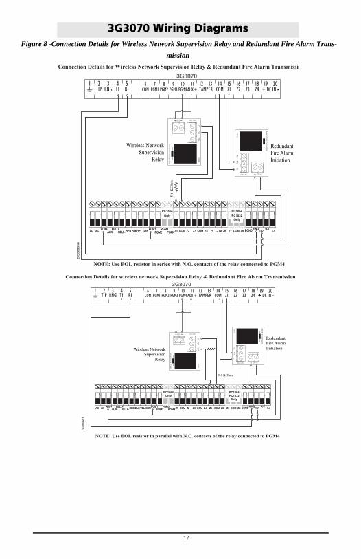
Figure 8 -Connection Details for Wireless Network Supervision Relay and Redundant Fire Alarm Trans-
mission
3G3070 Wiring Diagrams
DG
0096
56
5.6
KO
hm
Wireless Network
Supervision
Relay
Redundant
Fire Alarm
Initiation
541 2 3 6 7 8 9 10 11 14 15 16 17 18 19 20LE LI O1O2 O3 O4+OC
1312AS L1 L2 L3 L4 12V
3G307012 13TAMPER
9PGM3
8PGM2
19 20+ DC IN -
11AUX+
16Z2
17Z3
15Z1
14COM
10PGM4
7PGM1
6COM
4T1
5R1
2TIP
3RNG
1 18Z4
AC AC RED BLK YEL GRN Z1 COM Z2 Z3 COM Z4 Z5 COM Z6 Z7 COM Z8AUX+ BELL+AUX- BELL-
PGM1 PGM3 EGND TIP T-1PGM2 PGM4RING R-1
PC1864Only
PC1864PC1832
Only
AC AC RED BLK YEL GRN Z1 COM Z2 Z3 COM Z4 Z5 COM Z6 Z7 COM Z8AUX+ BELL+AUX- BELL-
PGM1 PGM3 EGND TIP T-1PGM2 PGM4RING R-1
PC1864Only
PC1864PC1832
Only
Connection Details for Wireless Network Supervision Relay & Redundant Fire Alarm Transmissio
NOTE: Use EOL resistor in series with N.O. contacts of the relay connected to PGM4
5.6 KOhm
Wireless Network
Supervision
Relay
Redundant
Fire Alarm
Initiation
DG
0096
57
541 2 3 6 7 8 9 10 11 14 15 16 17 18 19 20LE LI O1O2 O3 O4+OC
1312AS L1 L2 L3 L4 12V
3G307012 13TAMPER
9PGM3
8PGM2
11AUX+
16Z2
17Z3
15Z1
14COM
10PGM4
7PGM1
6COM
4T1
5R1
2TIP
3RNG
1 18Z4
AC AC RED BLK YEL GRN Z1 COM Z2 Z3 COM Z4 Z5 COM Z6 Z7 COM Z8AUX+ BELL+AUX- BELL-
PGM1 PGM3 EGND TIP T-1PGM2 PGM4RING R-1
PC1864Only
PC1864PC1832
Only
AC AC RED BLK YEL GRN Z1 COM Z2 Z3 COM Z4 Z5 COM Z6 Z7 COM Z8AUX+ BELL+AUX- BELL-
PGM1 PGM3 EGND TIP T-1PGM2 PGM4RING R-1
PC1864Only
PC1864PC1832
Only
Connection Details for wireless network Supervision Relay & Redundant Fire Alarm Transmission
NOTE: Use EOL resistor in parallel with N.C. contacts of the relay connected to PGM4
19 20+ DC IN -

18
Figure 9 - Connection Details for GSM Supervision Relay, Phone Line Supervision andRedundant Fire Alarm Transmission
3G3070 Wiring Diagrams
5.6
KO
hm
5.6
KO
hm
WirelessNetwork
SupervisionRelay
Phone LineSupervision
Relay
Redundant Fire AlarmInitiation
541 2 3 6 7 8 9 10 11 14 15 16 17 18 19 20LE LI O1O2 O3 O4+OC
1312AS L1 L2 L3 L4 12V
3G307012 13TAMPER
9PGM3
8PGM2
11AUX+
16Z2
17Z3
15Z1
14COM
10PGM4
7PGM1
6COM
4T1
5R1
2TIP
3RNG
1 18Z4
AC AC RED BLK YEL GRN Z1 COM Z2 Z3 COM Z4 Z5 COM Z6 Z7 COM Z8AUX+ BELL+AUX- BELL-
PGM1 PGM3 EGND TIP T-1PGM2 PGM4RING R-1
PC1864Only
PC1864PC1832
Only
AC AC RED BLK YEL GRN Z1 COM Z2 Z3 COM Z4 Z5 COM Z6 Z7 COM Z8AUX+ BELL+AUX- BELL-
PGM1 PGM3 EGND TIP T-1PGM2 PGM4RING R-1
PC1864Only
PC1864PC1832
Only
Connection Details for Wireless Network Supervision Relay, Phone Line Supervision Relay and Redundant Fire Alarm Transmission
NOTE: Use EOL resistor in series with N.O. contacts of the relay connected to PGM4
DG
0096
58
19 20+ DC IN -
5.6
KOhm
5.6
KOhm
WirelessNetwork
SupervisionRelay
Phone LineSupervision
Relay
Redundant Fire AlarmInitiation
541 2 3 6 7 8 9 10 11 14 15 16 17 18 19 20LE LI O1O2 O3 O4+OC
1312AS L1 L2 L3 L4 12V
3G307012 13TAMPER
9PGM3
8PGM2
11AUX+
16Z2
17Z3
15Z1
14COM
10PGM4
7PGM1
6COM
4T1
5R1
2TIP
3RNG
1 18Z4
AC AC RED BLK YEL GRN Z1 COM Z2 Z3 COM Z4 Z5 COM Z6 Z7 COM Z8AUX+ BELL+AUX- BELL-
PGM1 PGM3 EGND TIP T-1PGM2 PGM4RING R-1
PC1864Only
PC1864PC1832
Only
AC AC RED BLK YEL GRN Z1 COM Z2 Z3 COM Z4 Z5 COM Z6 Z7 COM Z8AUX+ BELL+AUX- BELL-
PGM1 PGM3 EGND TIP T-1PGM2 PGM4RING R-1
PC1864Only
PC1864PC1832
Only
Connection Details for Wireless Network Supervision Relay, Phone Line Supervision Relay
and Redundant Fire Alarm Transmission
NOTE: Use EOL resistor in parallel with N.C. contacts of the relay connected to PGM4
DG
0096
59
19 20+ DC IN -
19
IMPORTANT READ CAREFULLY: DSC Software purchased with or without Products and Components is copyrighted and is purchased under thefollowing license terms:• This End User License Agreement ("EULA") is a legal agreement
between You (the company, individual or entity who acquired the Soft-ware and any related Hardware) and Digital Security Controls, a divi-sion of Tyco Safety Products Canada Ltd. ("DSC"), the manufacturer ofthe integrated security systems and the developer of the software andany related products or components ("HARDWARE") which Youacquired.
• If the DSC software product ("SOFTWARE PRODUCT" or "SOFTWARE")is intended to be accompanied by HARDWARE, and is NOT accom-panied by new HARDWARE, You may not use, copy or install theSOFTWARE PRODUCT. The SOFTWARE PRODUCT includes com-puter software, and may include associated media, printed materials,and "online" or electronic documentation.
• Any software provided along with the SOFTWARE PRODUCT that isassociated with a separate end user license agreement is licensed toYou under the terms of that license agreement.
• By installing, copying, downloading, storing, accessing or otherwiseusing the SOFTWARE PRODUCT, You agree unconditionally to bebound by the terms of this EULA, even if this EULA is deemed to be amodification of any previous arrangement or contract. If You do notagree to the terms of this EULA, DSC is unwilling to license the SOFT-WARE PRODUCT to You, and You have no right to use it.
SOFTWARE PRODUCT LICENSE
The SOFTWARE PRODUCT is protected by copyright laws and interna-tional copyright treaties, as well as other intellectual property laws andtreaties. The SOFTWARE PRODUCT is licensed, not sold.
1. GRANT OF LICENSE. This EULA grants You the following rights:
(a) Software Installation and Use - For each license You acquire, Youmay have only one copy of the SOFTWARE PRODUCT installed. (b) Storage/Network Use - The SOFTWARE PRODUCT may not beinstalled, accessed, displayed, run, shared or used concurrently on orfrom different computers, including a workstation, terminal or other digi-tal electronic device ("Device"). In other words, if You have several work-stations, You will have to acquire a license for each workstation wherethe SOFTWARE will be used.(c) Backup Copy - You may make back up copies of the SOFTWAREPRODUCT, but You may only have one copy per license installed at anygiven time. You may use the back up copy solely for archival purposes.Except as expressly provided in this EULA, You may not otherwise makecopies of the SOFTWARE PRODUCT, including the printed materialsaccompanying the SOFTWARE.2. DESCRIPTION OF OTHER RIGHTS AND LIMITATIONS
(a) Limitations on Reverse Engineering, Decompilation and Disassembly- You may not reverse engineer, decompile, or disassemble the SOFT-WARE PRODUCT, except and only to the extent that such activity isexpressly permitted by applicable law notwithstanding this limitation.You may not make any changes or modifications to the Software, withoutthe written permission of an officer of DSC. You may not remove anyproprietary notices, marks or labels from the Software Product. You shallinstitute reasonable measures to ensure compliance with the terms andconditions of this EULA.(b) Separation of Components - The SOFTWARE PRODUCT is licensedas a single product. Its component parts may not be separated for useon more than one HARDWARE unit.(c) Single INTEGRATED PRODUCT - If You acquired this SOFTWAREwith HARDWARE, then the SOFTWARE PRODUCT is licensed with theHARDWARE as a single integrated product. In this case, the SOFT-WARE PRODUCT may only be used with the HARDWARE as set forth inthis EULA.(d) Rental - You may not rent, lease or lend the SOFTWARE PRODUCT.You may not make it available to others or post it on a server or web site.(e) Software Product Transfer - You may transfer all of Your rights underthis EULA only as part of a permanent sale or transfer of the HARD-WARE, provided You retain no copies, You transfer all of the SOFTWAREPRODUCT (including all component parts, the media and printed mate-rials, any upgrades and this EULA), and provided the recipient agreesto the terms of this EULA. If the SOFTWARE PRODUCT is an upgrade,any transfer must also include all prior versions of the SOFTWAREPRODUCT.(f) Termination - Without prejudice to any other rights, DSC may termi-nate this EULA if You fail to comply with the terms and conditions of thisEULA. In such event, You must destroy all copies of the SOFTWAREPRODUCT and all of its component parts.(g) Trademarks - This EULA does not grant You any rights in connectionwith any trademarks or service marks of DSC or its suppliers.
3. COPYRIGHT
All title and intellectual property rights in and to the SOFTWARE PROD-UCT (including but not limited to any images, photographs, and textincorporated into the SOFTWARE PRODUCT), the accompanyingprinted materials, and any copies of the SOFTWARE PRODUCT, areowned by DSC or its suppliers. You may not copy the printed materialsaccompanying the SOFTWARE PRODUCT. All title and intellectual prop-erty rights in and to the content which may be accessed through use ofthe SOFTWARE PRODUCT are the property of the respective contentowner and may be protected by applicable copyright or other intellec-tual property laws and treaties. This EULA grants You no rights to usesuch content. All rights not expressly granted under this EULA arereserved by DSC and its suppliers.4. EXPORT RESTRICTIONS
You agree that You will not export or re export the SOFTWARE PROD-UCT to any country, person, or entity subject to Canadian export restric-tions. 5. CHOICE OF LAW: This Software License Agreement is governed bythe laws of the Province of Ontario, Canada.
6. ARBITRATION
All disputes arising in connection with this Agreement shall be deter-mined by final and binding arbitration in accordance with the ArbitrationAct, and the parties agree to be bound by the arbitrator's decision. Theplace of arbitration shall be Toronto, Canada, and the language of thearbitration shall be English.7. LIMITED WARRANTY
(a) NO WARRANTYDSC PROVIDES THE SOFTWARE "AS IS" WITHOUT WARRANTY. DSCDOES NOT WARRANT THAT THE SOFTWARE WILL MEET YOURREQUIREMENTS OR THAT OPERATION OF THE SOFTWARE WILL BEUNINTERRUPTED OR ERROR-FREE.(b) CHANGES IN OPERATING ENVIRONMENTDSC shall not be responsible for problems caused by changes in theoperating characteristics of the HARDWARE, or for problems in the inter-action of the SOFTWARE PRODUCT with non-DSC-SOFTWARE orHARDWARE PRODUCTS.(c) LIMITATION OF LIABILITY; WARRANTY REFLECTS ALLOCATION OFRISK IN ANY EVENT, IF ANY STATUTE IMPLIES WARRANTIES OR CONDI-TIONS NOT STATED IN THIS LICENSE AGREEMENT, DSC'S ENTIRELIABILITY UNDER ANY PROVISION OF THIS LICENSE AGREEMENTSHALL BE LIMITED TO THE GREATER OF THE AMOUNT ACTUALLYPAID BY YOU TO LICENSE THE SOFTWARE PRODUCT AND FIVECANADIAN DOLLARS (CAD$5.00). BECAUSE SOME JURISDICTIONSDO NOT ALLOW THE EXCLUSION OR LIMITATION OF LIABILITY FORCONSEQUENTIAL OR INCIDENTAL DAMAGES, THE ABOVE LIMITA-TION MAY NOT APPLY TO YOU.(d) DISCLAIMER OF WARRANTIESTHIS WARRANTY CONTAINS THE ENTIRE WARRANTY AND SHALL BEIN LIEU OF ANY AND ALL OTHER WARRANTIES, WHETHEREXPRESSED OR IMPLIED (INCLUDING ALL IMPLIED WARRANTIES OFMERCHANTABILITY OR FITNESS FOR A PARTICULAR PURPOSE) ANDOF ALL OTHER OBLIGATIONS OR LIABILITIES ON THE PART OF DSC.DSC MAKES NO OTHER WARRANTIES. DSC NEITHER ASSUMES NORAUTHORIZES ANY OTHER PERSON PURPORTING TO ACT ON ITSBEHALF TO MODIFY OR TO CHANGE THIS WARRANTY, NOR TOASSUME FOR IT ANY OTHER WARRANTY OR LIABILITY CONCERNINGTHIS SOFTWARE PRODUCT.(e) EXCLUSIVE REMEDY AND LIMITATION OF WARRANTYUNDER NO CIRCUMSTANCES SHALL DSC BE LIABLE FOR ANY SPE-CIAL, INCIDENTAL, CONSEQUENTIAL OR INDIRECT DAMAGESBASED UPON BREACH OF WARRANTY, BREACH OF CONTRACT,NEGLIGENCE, STRICT LIABILITY, OR ANY OTHER LEGAL THEORY.SUCH DAMAGES INCLUDE, BUT ARE NOT LIMITED TO, LOSS OFPROFITS, LOSS OF THE SOFTWARE PRODUCT OR ANY ASSOCIATEDEQUIPMENT, COST OF CAPITAL, COST OF SUBSTITUTE OR REPLACE-MENT EQUIPMENT, FACILITIES OR SERVICES, DOWN TIME, PUR-CHASERS TIME, THE CLAIMS OaF THIRD PARTIES, INCLUDING CUS-TOMERS, AND INJURY TO PROPERTY.
WARNING: DSC recommends that the entire system be completelytested on a regular basis. However, despite frequent testing, and due to,but not limited to, criminal tampering or electrical disruption, it is possi-ble for this SOFTWARE PRODUCT to fail to perform as expected.

FCC COMPLIANCE STATEMENTCAUTION: Changes or modifications not expressly approved byDigital Security Controls could void your authority to use thisequipment. This equipment generates and uses radio frequency energyand if not installed and used properly, in strict accordance with themanufacturer's instructions, may cause interference to radio andtelevision reception. It has been type tested and found to comply withthe limits for Class B device in accordance with the specifications inSubpart "B" of Part 15 of FCC Rules, which are designed to providereasonable protection against such interference in any residentialinstallation. However, there is no guarantee that interference will notoccur in a particular installation. If this equipment does causeinterference to television or radio reception, which can be determinedby turning the equipment off and on, the user is encouraged to try tocorrect the interference by one or more of the following measures: • Re-orient the receiving antenna• Relocate the alarm control with respect to the receiver• Move the alarm control away from the receiver• Connect the alarm control into a different outlet so that alarm controland receiver are on different circuits.If necessary, the user should consult the dealer or an experienced radio/television technician for additional suggestions. The user may find thefollowing booklet prepared by the FCC helpful: "How to Identify andResolve Radio/Television Interference Problems". This booklet isavailable from the U.S. Government Printing Office, Washington, D.C.20402, Stock # 004-000-00345-4.IMPORTANT INFORMATIONThis equipment complies with Part 68 of the FCC Rules. On the side ofthis equipment is a label that contains, among other information, theFCC registration number and ringer equivalence number (REN) for thisequipment. If requested, this number must be provided to theTelephone Company.3G3070 Product IdentifierUS: F53MO00B3G3070REN:0.0BUSOC Jack:RJ-31XTelephone Connection RequirementsA plug and jack used to connect this equipment to the premises wiringand telephone network must comply with the applicable FCC Part 68rules and requirements adopted by the ACTA. A compliant telephonecord and modular plug is provided with this product. It is designed tobe connected to a compatible modular jack that is also compliant. Seeinstallation instructions for details.Ringer Equivalence Number (REN)The REN is used to determine the number of devices that may beconnected to a telephone line. Excessive RENs on a telephone line mayresult in the devices not ringing in response to an incoming call.In most but not all areas, the sum of RENs should not exceed five (5.0).To be certain of the number of devices that may be connected to a line,as determined by the total RENs, contact the local TelephoneCompany. For products approved after July 23, 2001, the REN for thisproduct is part of the product identifier that has the format. US:AAAEQ##TXXXX. The digits represented by ## are the REN withouta decimal point (e.g., 03 is a REN of 0.3). For earlier products, the RENis separately shown on the label.Incidence of HarmIf this equipment 3G3070 causes harm to the telephone network, thetelephone company will notify you in advance that temporarydiscontinuance of service may be required. But if advance notice is notpractical, the Telephone Company will notify the customer as soon aspossible. Also, you will be advised of your right to file a complaint withthe FCC if you believe it is necessary.Changes in Telephone Company Equipment or FacilitiesThe Telephone Company may make changes in its facilities,equipment, operations or procedures that could affect the operation ofthe equipment. If this happens the Telephone Company will provideadvance notice in order for you to make necessary modifications tomaintain uninterrupted service.Equipment Maintenance FacilityIf trouble is experienced with this equipment for repair or warrantyinformation, please contact the facility indicated below. If theequipment is causing harm to the telephone network, the Telephone
Company may request that you disconnect the equipment until the problemis solved. This equipment is of a type that is not intended to be repaired bythe end user.DSC c/o APL Logistics, 757 Douglas Hill Rd., Lithia Springs, GA 30122Additional InformationConnection to party line service is subject to state tariffs. Contact the statepublic utility commission, public service commission or corporationcommission for information.Alarm dialling equipment must be able to seize the telephone line and placea call in an emergency situation. It must be able to do this even if otherequipment (telephone, answering system, computer modem, etc.) alreadyhas the telephone line in use. To do so, alarm dialling equipment must beconnected to a properly installed RJ-31X jack that is electrically in serieswith and ahead of all other equipment attached to the same telephone line.Proper installation is depicted in the figure below. If you have anyquestions concerning these instructions, you should consult your telephonecompany or a qualified installer about installing the RJ-31X jack and alarmdialling equipment foryou.
Industry Canada Compliance StatementThis Equipment meets the applicable Industry Canada Terminal EquipmentTechnical Specifications. This is confirmed by the registration number.The abbreviation, IC, before the registration number signifies thatregistration was performed based on a Declaration of Conformityindicating that Industry Canada technical specifications were met. It doesnot imply that that Industry Canada approved the equipment. The RingerEquivalence Number (REN) for this terminal equipment is 0.0. The RENassigned to each terminal equipment provides an indication of themaximum number of terminals allowed to be connected to a telephoneinterface. The termination on an interface may consist of any combinationof devices subject only to the requirement that the sum of the RingerEquivalence Numbers of all devices does not exceed 5.Cet équipement est conforme aux spécifications techniques applicables auxéquipements terminaux d'Industrie Canada. Ceci est confirmé par lenuméro d'enregistrement. L'abréviation IC précédant le numérod'enregistrement signifie que l'enregistrement a été effectué sur la base dela Déclaration de conformité indiquant que le produit est conforme auxspécifications techniques d'Industrie Canada. Ceci n'implique pas que leproduit ait été approuvé par Industrie Canada.Le nombre équivalent de sonneries (REN) de cet appareil terminal est 0.0.Le REN attribué à chaque équipement terminal fournit une indication surle nombre maximum de terminaux pouvant être connectés sur une interfacetéléphonique. La terminaison sur une interface peut constituer en n'importequelle combinaison d'appareils, à la condition seulement que la somme desNombres équivalents de sonneries de tous les appareils ne soit passupérieure à 5.This Class B digital apparatus meets all requirements of the Canadianinterference-causing equipment regulations. Cet appareil numérique de laClasse B respecte toutes les exigences de règlement sur le matérielbrouilleur du Canada.The term “IC:” before the radio certification number only signifies that Industry Canada technical specifications were met.
WARNING: To satisfy FCC RF exposure requirements for mobile transmitting devices, a separation distance of 20cm or more must be maintained between the antenna of this device and persons during device operation.
Tech Support: 1-800-387-3630 (Canada & US) or 905-760-30000 - www.dsc.comPrinted in Canada 2 9 0 0 8 1 8 1 R0 0 1
© 2012 Tyco International Ltd. and its Respective Companies. All Rights Reserved.The trademarks, logos, and service marks displayed on this document are registered in the United States [or othercountries]. Any misuse of the trademarks is strictly prohibited and Tyco International Ltd. will aggressively enforce itsintellectual property rights to the fullest extent of the law, including pursuit of criminal prosecution wherever necessary. Alltrademarks not owned by Tyco International Ltd. are the property of their respective owners, and are used with permissionor allowed under applicable laws. Product offerings and specifications are subject to change without notice. Actual products may vary from photos. Not allproducts include all features. Availability varies by region; contact your sales representative.
Limited WarrantyDigital Security Controls warrants the original purchaser that for a period of twelve months from the date of purchase, the product shall be free of defects in materials and workmanship under normal use. During the warranty period, Digital Security Controls shall, at its option, repair or replace any defective product upon return of the prod-uct to its factory, at no charge for labour and materials. Any replacement and/or repaired parts are warranted for the remainder of the original warranty or ninety (90) days, whichever is longer. The original purchaser must promptly notify Digital Security Controls in writing that there is defect in material or workmanship, such written notice to be received in all events prior to expiration of the warranty period. There is absolutely no warranty on software and all software products are sold as a user license under the terms of the software license agree-ment included with the product. The Customer assumes all responsibility for the proper selection, installation, operation and maintenance of any products purchased from DSC. Custom products are only warranted to the extent that they do not function upon delivery. In such cases, DSC can replace or credit at its option.International WarrantyThe warranty for international customers is the same as for any customer within Canada and the United States, with the exception that Digital Security Controls shall not be responsible for any customs fees, taxes, or VAT that may be due.Warranty ProcedureTo obtain service under this warranty, please return the item(s) in question to the point of purchase. All autho-rized distributors and dealers have a warranty program. Anyone returning goods to Digital Security Controls must first obtain an authorization number. Digital Security Controls will not accept any shipment whatsoever for which prior authorization has not been obtained.Conditions to Void WarrantyThis warranty applies only to defects in parts and work-manship relating to normal use. It does not cover:• damage incurred in shipping or handling;• damage caused by disaster such as fire, flood, wind,
earthquake or lightning;• damage due to causes beyond the control of Digital
Security Controls such as excessive voltage, mechanical shock or water damage;
• damage caused by unauthorized attachment, altera-tions, modifications or foreign objects;
• damage caused by peripherals (unless such peripherals were supplied by Digital Security Controls);
• defects caused by failure to provide a suitable installa-tion environment for the products;
• damage caused by use of the products for purposes other than those for which it was designed;
• damage from improper maintenance;• damage arising out of any other abuse, mishandling or
improper application of the products.Items Not Covered by WarrantyIn addition to the items which void the Warranty, the following items shall not be covered by Warranty: (i) freight cost to the repair centre; (ii) products which are not identified with DSC's product label and lot number or serial number; (iii) products disassembled or repaired in such a manner as to adversely affect performance or
prevent adequate inspection or testing to verify any war-ranty claim. Access cards or tags returned for replace-ment under warranty will be credited or replaced at DSC's option. Products not covered by this warranty, or other-wise out of warranty due to age, misuse, or damage shall be evaluated, and a repair estimate shall be provided. No repair work will be performed until a valid purchase order is received from the Customer and a Return Merchandise Authorisation number (RMA) is issued by DSC's Customer Service.Digital Security Controls’ liability for failure to repair the product under this warranty after a reasonable number of attempts will be limited to a replacement of the product, as the exclusive remedy for breach of warranty. Under no circumstances shall Digital Security Controls be liable for any special, incidental, or consequential damages based upon breach of warranty, breach of contract, negligence, strict liability, or any other legal theory. Such damages include, but are not limited to, loss of profits, loss of the product or any associated equipment, cost of capital, cost of substitute or replacement equipment, facilities or ser-vices, down time, purchaser’s time, the claims of third parties, including customers, and injury to property. The laws of some jurisdictions limit or do not allow the dis-claimer of consequential damages. If the laws of such a jurisdiction apply to any claim by or against DSC, the limitations and disclaimers contained here shall be to the greatest extent permitted by law. Some states do not allow the exclusion or limitation of incidental or conse-quential damages, so that the above may not apply to you.Disclaimer of WarrantiesThis warranty contains the entire warranty and shall be in lieu of any and all other warranties, whether expressed or implied (including all implied warranties of merchantabil-ity or fitness for a particular purpose) and of all other obligations or liabilities on the part of Digital Security Controls Digital Security Controls neither assumes responsibility for nor authorizes any other person pur-porting to act on its behalf to modify or to change this warranty, nor to assume for it any other warranty or liability concerning this product.This disclaimer of warranties and limited warranty are governed by the laws of the province of Ontario, Canada.WARNING: Digital Security Controls recommends that the entire system be completely tested on a regular basis. However, despite frequent testing, and due to, but not limited to, criminal tampering or electrical disruption, it is possible for this product to fail to perform as expected.Out of Warranty RepairsDigital Security Controls will at its option repair or replace out-of-warranty products which are returned to its fac-tory according to the following conditions. Anyone returning goods to Digital Security Controls must first obtain an authorization number. Digital Security Controls will not accept any shipment whatsoever for which prior authorization has not been obtained.Products which Digital Security Controls determines to be repairable will be repaired and returned. A set fee which Digital Security Controls has predetermined and which may be revised from time to time, will be charged for each unit repaired.