2nd lspa generator at sans souci 500kv switchyard osceola, arkansas€¦ · · 2007-04-262nd lspa...
TRANSCRIPT
TRANSMISSION / DISTRIBUTION PROJECTS
COMPANY: EAI
CUSTOMER: LS POWER
FACITLIY STUDY EJO # F4PPAR0401
2ND LSPA GENERATOR AT SANS SOUCI 500KV SWITCHYARD OSCEOLA, ARKANSAS
Revision: 1
Rev Issue
Date Description of Revision Program Manager
Project Manager
0 02/27/07 Issued to ICT Mike Gravolet
Douglas Bowman
1 04/24/07 Upgrades Classified
Table of Contents
Section Title 1 EXECUTIVE SUMMARY…………………………………………….….…..3 2 SCOPE SUMMARY………………………………………………… ……...3 3 SCOPE DETAILS – SUBSTATIONS……………………………… ……..4 4 SCOPE DETAILS – TRANSMISSION LINES……………………….….11 5 PERMIT REQUIREMENTS…………………………………………..…...14 6 ENVIRONMENTAL REQUIREMENTS…………………………….…....15 7 CONSTRUCTION PLAN…………………………………………………..16 8 SAFETY PLAN……………………………………………………………..21 9 ASSUMPTIONS………………………………………………………….…24 10 PROJECTED SCHEDULE………………………………………….….….25 11 PROJECTED COST……………………………………………….……….26 12 PROJECT TEAM MEMBERS………………………………………..…....27 13 ATTACHMENT A – SUBSTATION ONE- LINE DIAGRAMS….……....28 14 ATTACHMENT B – TRANSMISSION LINE UPGRADES MAP……....32
PID198_Facility_Study_rev1.doc 04/25/07 Page 2 of 32
1. EXECUTIVE SUMMARY
LS Power Associates, LP (LSPA) submitted a request for a System Impact Study (SIS) as required by the Large Generator Interconnection Process (LGIP) for adding a new generation facility in Osceola, Arkansas. The new 820 MVA generating station would inject approximately 700 MW into the Entergy transmission system. As part of the SIS, LSPA requested to be studied to provide Network Resource Interconnection Service (NRIS). Network Resource Interconnection Service in and of itself does not convey transmission service. However, NRIS allows Interconnection Customer's Large Generating Facility to be designated by any Network Customer under the Tariff on Transmission Provider's Transmission System as a Network Resource, up to the Large Generating Facility's full output, on the same basis as existing Network Resources interconnected to Transmission Provider's Transmission System. Designation of an NRIS unit as a Network Resource may incur congestion costs. The NRIS study was performed in accordance with Attachment N-1 to Entergy’s OATT. The study identified transmission limitations that prevented the facility from delivering full capability into the system and recommend upgrades to remove those limitations.
LSPA requested a facility study to provide a +/- 20% estimated cost of the necessary transmission upgrades. Final cost will include overheads and AFUDC. The estimated cost of these transmission facilities does not include a grossed-up cost of Entergy’s income tax burden. However these tax gross-ups will apply.
Cost responsibility for the required upgrades will be determined per the procedures contained in Attachment T to Entergy’s OATT. After this Facilities Study was commenced on the basis of the SIS results, LSPA requested that Entergy review the impact of adding a new 500/161 kV substation as one solution to obtain NRIS status. Entergy performed that analysis and presented the results to LSPA, including an order of magnitude cost estimate for the work required under that option. Because no direction was received from LSPA to prepare a +/- 20% estimate for those costs, that option has not been included in this Facilities Study. 2. SCOPE SUMMARY
2.1 The following 161kV transmission substations require upgrades:
• Jonesboro 161kV Substation
• Paragould 161kV Substation
• Monette Junction 161kV Switching Station
• Dell 161kV Substation
PID198_Facility_Study_rev1.doc 04/25/07 Page 3 of 32
• Sans Souci 500kV Switchyard
2.2 The following 161kV transmission lines require upgrades:
• Jonesboro - Jonesboro North
• Jonesboro North. - Paragould South. AECC
• Paragould – Monette Junction
• Monette Junction - Manilla AECC
• Manilla AECC – Dell
3. SCOPE DETAILS - SUBSTATIONS
3.1 Jonesboro 161kV Substation
3.1.1
Foundation Work
No Foundation Work is required for this site
3.1.2
Electrical Work
• Remove and replace existing 366 kcmil ACSR conductor risers and OCB B7570 jumpers with approximately 500 ft of new 666 kcmil ACSR conductor.
• Remove and replace copper bus to aluminum flat bar (1/2” X 4 ¼”) rated ampacity 1950 amps with approximately 200 ft of new aluminum flat bar (1/2” X 4 ¼”).
• Install (3) 161kV station post insulators
• Install (3) 161kV suspension insulators and associated hardware
3.1.3
Relay Settings Work
• Calculate new line impedances on the Paragould Line due to re-conductoring of the line and update system model as needed. Review and revise as necessary the relay settings on the Paragould Line to compensate for line impedance changes. Review and, if necessary, make changes to relays on all other lines and system autotransformers terminating on the Jonesboro 161 kV bus.
PID198_Facility_Study_rev1.doc 04/25/07 Page 4 of 32
3.2 Jonesboro North 161kV Substation
• No Work
3.3 Paragould South AECC 161kV Substation
• No Work
3.4 Paragould 161kV Substation
Foundation Work
• Install grounding and conduit for motor operator device (MOD)
Electrical Work
• Install (1) 161kV 2000 amp vertical break disconnect switch B6673
• Install (1) 125VDC (MOD)
• Install (12) 161kV station post insulators
• Replace and install (400) ft of 666 kcmil ACSR conductor from transmission line to switch
• Install (3) 161kV suspension insulators and associated hardware
Relay Work
Add a motor operator mechanism to switch B6673. This will require new AC, DC, control, alarm, and indication cables. This station has stand alone AC & DC panels with spare circuit breakers. The station has a D20 Remote Terminal Unit, (RTU) with sufficient spare alarm and control points needed for the motor operator. The only material required for this project will be control cable. An RTU configuration package will be needed for this project.
Relay Settings Work
• Calculate new line impedances on the Jonesboro Line due to re-conductoring of the line and update system model as needed. Review and revise as necessary the relay settings on the Jonesboro Line to compensate for line impedance changes. Review and, if necessary, make changes to relays on all other lines and system autotransformers terminating on the Paragould 161 kV bus.
PID198_Facility_Study_rev1.doc 04/25/07 Page 5 of 32
• Calculate new line impedances on the Dell Line due to re-conductoring of the line and update system model as needed. Review and revise as necessary the relay settings on the Dell Line to compensate for line impedance changes.
3.5 Monette Junction 161kV Switching Station:
Foundation Work
• Perform a grounding and lightning study
• Upgrade existing ground grid to accommodate new equipment
• Install conduit for (2) new MOD’s
Install following required foundations
• Install (2) foundations for 42’ lattice A towers
Electrical Work
• Install (2) 42’ lattice A towers
• Install (2) 2000 amp vertical break switches B5473 and B2666
• Install (2) line interrupting devices
• Install (2) 125VDC MOD’s
• Install 500’ of 666 kcmil ACSR conductor for operating bus
• Install (18) 161kV station post insulators
• Install (12) 161kV suspension insulators with hardware
Relay Work
Replace the motor operators on switches B5473 and B2666. This will require new AC, DC, control, alarm, and indication cables. Available print information does not exist for the AC and DC panels. If the existing circuit breakers and circuit configuration are adequate for the new motor operators they can be reused. If not, additional capacity will be required. The station has a NW-ALERT RTU and the existing control and indication points will be reused. The RTU has capacity for the additional alarm points. The material required for this project will be control cable and possibly an AC/DC panel(s) depending on existing panel capacity. No relay settings will be required but an RTU configuration package will be needed for this project.
PID198_Facility_Study_rev1.doc 04/25/07 Page 6 of 32

3.6 Manilla AECC 161kV Substation
• No Work
3.7 Dell 500/161kV Substation
Relay Settings Work
• Calculate new line impedances on the Paragould Line due to re-conductoring of the line and update system model as needed. Review and revise as necessary the relay settings on the Paragould Line to compensate for line impedance changes. Review and, if necessary, make changes to relays on all other lines and system autotransformers terminating on the Dell 161 kV bus.
3.8 Sans Souci 500kV Switchyard
Foundation Work
Install the following required foundations
• Install (1) 70’ 500kV dead end tower
• Install (45) 500kV high bus support foundations
• Install (10) 500kV low bus support foundations
• Install (1) 500kV high switch stand high bus
• Install (1) 500kV high switch stand low bus
• Install (1) 500kV breaker foundation
• Install (4) 500kV CCVT foundations
• Install (3) 500kV CT foundations
• Install (2) shieldwire tower foundations
• Install conduits for new equipment
• Upgrade ground grid to accommodate new equipment
Electrical Work
Purchase the following structures
• (1) 70’ 500kV dead end tower
PID198_Facility_Study_rev1.doc 04/25/07 Page 7 of 32
• (45) 500kV high bus structures
• (10) 500kV low bus structures
• (1) 500kV switch stand high bus
• (1) 500kV switch stand low bus
• (4) 500kV CCVT structures
• (3) 500kV CCVT structures
• (3) 500kV arrester structures
• (2) Shieldwire towers
Install the following equipment
• (3) 500kV, 335kV rated MCOV arresters
• (1) 500kV, 3000amp vertical break switch with ground switch
• (1) 500kV, 3000amp vertical break switch
• (2) 125VDC MOD’s
• (1) 500kV, 3000 amp, 63kA dead tank gas circuit breaker
• (72) 500kV station post insulators
• (4,000) feet of 6” SCH 40, SPS, Aluminum tube
• (4,000) feet of 666 kcmil ACSR conductor for bus damping
• (1,000) feet of 954 kcmil ACSR conductor for equipment connection
• (500) feet of 7#7 Alumoweld shieldwire
Relay Work
Install One Breaker Control Panel
The new installed circuit breaker will require its own breaker control panel. The breaker control panels shall be arranged to mimic the physical layout of the ring bus. .
• Purchase and design one breaker control panel using Entergy’s standard design. The protection standard number is PM0501, Rev. 04. The breaker control panel shall include controls for the motor operated disconnect switches for the breakers.
Install One Line Current Differential Panel
PID198_Facility_Study_rev1.doc 04/25/07 Page 8 of 32
This line panel shall protect the transmission lines between PPES and the San Souci 500 kV switching station. The Schweitzer type SEL-311L relay and the Schweitzer type SEL-421 relay, over fiber optic communication cables, shall be used to provide dual primary protection for the very short transmission line. The SEL-311L relay shall provide current differential protection. The SEL-421 relay shall utilize a Permissive Overreach Transfer Trip (POTT) scheme for high speed tripping. Both relays shall also provide Direct Transfer Trip (DTT) to PPES for breaker failure.
• Purchase and design a transmission line panel using Schweitzer type SEL-311L and SEL-421 relays to protect the transmission line between PPES and the San Souci 500 kV switching station. A copy of Entergy’s transmission line panel design must be shared with PPES’s design consultants to ensure that the panels at each end of the transmission line are identical.
• Both relays shall communicate over an OPTGW fiber optic cable connection. The mirrored bit logic in the SEL-421 shall be used for this installation.
• A control switch shall be required for the motor operated line disconnect switch and will be part of this line panel.
The OPTGW fiber optic cable shall be installed in the shield wire position on the transmission towers. In addition to the OPTGW fiber optic cable, splice boxes, ADSS fiber optic cables and patch panels will be needed to complete the fiber optic communication circuit. The ADSS fiber optic cables must be installed in inner-duct for protection. The procurement of the fiber optic cable and equipment should be coordinated with Entergy’s Telecommunications Group in Arkansas.
• Purchase and design the 3 CVT’s without carrier accessories to provide line potential to primary and backup relays on the PPES line and to provide line potential to the metering panel for this line. These CVT’s will be installed after the disconnect switch and the secondaries will terminate in a relay potential junction box.
• Purchase and design the 1 CVT without carrier accessories to provide hot line indication This CVT will be installed ahead of the line disconnect switch on the PPEA line and the secondaries will terminate in a relay potential junction box.
• Purchase and design the 3 metering accuracy 500 kV CT’s, capable of maintaining revenue class accuracy during minimal load conditions, installed after the line disconnect switch and ahead of the bus on the PPEA line. Ratio to be specified at a later date when load data becomes known.
The CVT’s for this project must be purchased according to Entergy Standard PN0202, Rev. 02. According to the standard this project warrants EHC-CVT’s. The EHC stands for extra high capacitance. Metering CVT’s and CT’s to have a minimum accuracy class of 0.3.
PID198_Facility_Study_rev1.doc 04/25/07 Page 9 of 32

Revenue Metering
Entergy’s Generator Interconnection Customer Requirements Standard, PM3901, requires the installation of revenue class metering at each point of interconnection; therefore, a Class 20 revenue meter panel and associated metering equipment will be required for this project. The output of the meter, at the point of interconnection, will be given to the System Operating System (SOC) via an analog point in the RTU. A meter pulse isolation relay will also be installed to multiply the meter K, Y, Z pulses to provide outputs to Entergy and PPEA. Entergy will also require an additional set of revenue class metering to meter the generator’s auxiliary load; however, there is not enough details to complete the scope of work associated with this metering. The auxiliary meters will only be activated when PPEA is not generating power into the Entergy system. An analog point to the RTU and meter pulses will also be required for the auxiliary load metering. No cost has been included in this project for auxiliary metering.
• Purchase and design a single meter revenue metering panel. • Note: The revenue metering is a separate line item in the estimate.
Control Cables
All control cables that run through the 500kV switchyard must be shielded cables. Also, if extremely long cable runs are required to some of the substation devices, it will be necessary to calculate voltage drops to ensure proper conductor sizing for all supply cables.
The shielded conductor should be connected to ground at only one point. The end that is not grounded should be pulled back and taped.
All panels purchased for this project should be manufactured with accessible means for attaching the shields to the panel.
Relay Settings
Relay settings will be required for all the relay panels. One Entergy standard Breaker Control Panel. One Line current differential panel with a Schweitzer type SEL-311L relay and a Schweitzer type SEL-421 relay for the interconnection between Entergy and PPES’s plant.
Entergy will provide relay settings for the new PPES Line Panel. (Panel supplied and installed by PPES)
RTU Configuration
A configuration package will be required for this project.
PID198_Facility_Study_rev1.doc 04/25/07 Page 10 of 32
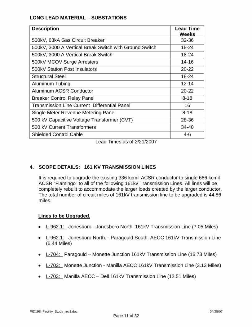
LONG LEAD MATERIAL – SUBSTATIONS
Description Lead Time Weeks
500kV, 63kA Gas Circuit Breaker 32-36 500kV, 3000 A Vertical Break Switch with Ground Switch 18-24 500kV, 3000 A Vertical Break Switch 18-24 500kV MCOV Surge Arresters 14-16 500kV Station Post Insulators 20-22 Structural Steel 18-24 Aluminum Tubing 12-14 Aluminum ACSR Conductor 20-22 Breaker Control Relay Panel 8-18 Transmission Line Current Differential Panel 16 Single Meter Revenue Metering Panel 8-18 500 kV Capacitive Voltage Transformer (CVT) 28-36 500 kV Current Transformers 34-40 Shielded Control Cable 4-6
Lead Times as of 2/21/2007
4. SCOPE DETAILS: 161 KV TRANSMISSION LINES
It is required to upgrade the existing 336 kcmil ACSR conductor to single 666 kcmil ACSR “Flamingo” to all of the following 161kv Transmission Lines. All lines will be completely rebuilt to accommodate the larger loads created by the larger conductor. The total number of circuit miles of 161kV transmission line to be upgraded is 44.86 miles.
Lines to be Upgraded. • L-962.1: Jonesboro - Jonesboro North. 161kV Transmission Line (7.05 Miles)
• L-962.1: Jonesboro North. - Paragould South. AECC 161kV Transmission Line (5.44 Miles)
• L-704: Paragould – Monette Junction 161kV Transmission Line (16.73 Miles)
• L-703: Monette Junction - Manilla AECC 161kV Transmission Line (3.13 Miles)
• L-703: Manilla AECC – Dell 161kV Transmission Line (12.51 Miles)
PID198_Facility_Study_rev1.doc 04/25/07 Page 11 of 32
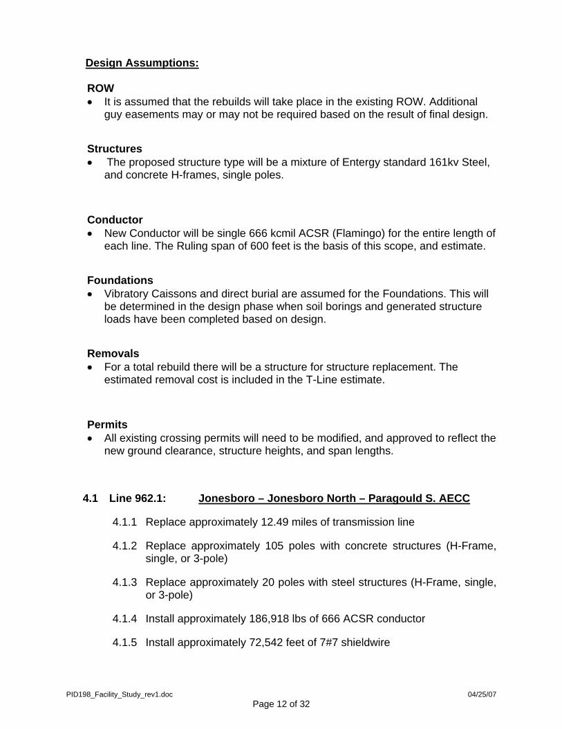
Design Assumptions: ROW • It is assumed that the rebuilds will take place in the existing ROW. Additional
guy easements may or may not be required based on the result of final design.
Structures • The proposed structure type will be a mixture of Entergy standard 161kv Steel,
and concrete H-frames, single poles.
Conductor • New Conductor will be single 666 kcmil ACSR (Flamingo) for the entire length of
each line. The Ruling span of 600 feet is the basis of this scope, and estimate.
Foundations • Vibratory Caissons and direct burial are assumed for the Foundations. This will
be determined in the design phase when soil borings and generated structure loads have been completed based on design.
Removals • For a total rebuild there will be a structure for structure replacement. The
estimated removal cost is included in the T-Line estimate.
Permits • All existing crossing permits will need to be modified, and approved to reflect the
new ground clearance, structure heights, and span lengths.
4.1 Line 962.1: Jonesboro – Jonesboro North – Paragould S. AECC
4.1.1 Replace approximately 12.49 miles of transmission line
4.1.2 Replace approximately 105 poles with concrete structures (H-Frame, single, or 3-pole)
4.1.3 Replace approximately 20 poles with steel structures (H-Frame, single, or 3-pole)
4.1.4 Install approximately 186,918 lbs of 666 ACSR conductor
4.1.5 Install approximately 72,542 feet of 7#7 shieldwire
PID198_Facility_Study_rev1.doc 04/25/07 Page 12 of 32
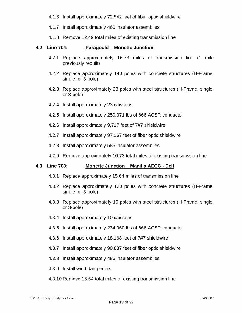
4.1.6 Install approximately 72,542 feet of fiber optic shieldwire
4.1.7 Install approximately 460 insulator assemblies
4.1.8 Remove 12.49 total miles of existing transmission line
4.2 Line 704: Paragould – Monette Junction
4.2.1 Replace approximately 16.73 miles of transmission line (1 mile previously rebuilt)
4.2.2 Replace approximately 140 poles with concrete structures (H-Frame, single, or 3-pole)
4.2.3 Replace approximately 23 poles with steel structures (H-Frame, single, or 3-pole)
4.2.4 Install approximately 23 caissons
4.2.5 Install approximately 250,371 lbs of 666 ACSR conductor
4.2.6 Install approximately 9,717 feet of 7#7 shieldwire
4.2.7 Install approximately 97,167 feet of fiber optic shieldwire
4.2.8 Install approximately 585 insulator assemblies
4.2.9 Remove approximately 16.73 total miles of existing transmission line
4.3 Line 703: Monette Junction – Manilla AECC - Dell
4.3.1 Replace approximately 15.64 miles of transmission line
4.3.2 Replace approximately 120 poles with concrete structures (H-Frame, single, or 3-pole)
4.3.3 Replace approximately 10 poles with steel structures (H-Frame, single, or 3-pole)
4.3.4 Install approximately 10 caissons
4.3.5 Install approximately 234,060 lbs of 666 ACSR conductor
4.3.6 Install approximately 18,168 feet of 7#7 shieldwire
4.3.7 Install approximately 90,837 feet of fiber optic shieldwire
4.3.8 Install approximately 486 insulator assemblies
4.3.9 Install wind dampeners
4.3.10 Remove 15.64 total miles of existing transmission line
PID198_Facility_Study_rev1.doc 04/25/07 Page 13 of 32
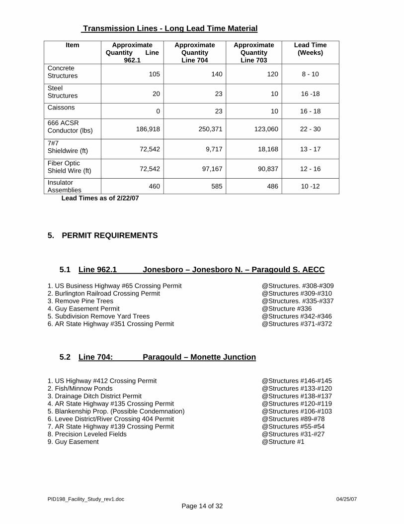
Transmission Lines - Long Lead Time Material
Item Approximate Quantity Line
962.1
Approximate Quantity Line 704
Approximate Quantity Line 703
Lead Time (Weeks)
Concrete Structures 105 140 120 8 - 10
Steel Structures 20 23 10 16 -18
Caissons 0 23 10 16 - 18
666 ACSR Conductor (lbs) 186,918 250,371 123,060 22 - 30
7#7 Shieldwire (ft) 72,542 9,717 18,168 13 - 17
Fiber Optic Shield Wire (ft) 72,542 97,167 90,837 12 - 16
Insulator Assemblies 460 585 486 10 -12
Lead Times as of 2/22/07
5. PERMIT REQUIREMENTS
5.1 Line 962.1 Jonesboro – Jonesboro N. – Paragould S. AECC
1. US Business Highway #65 Crossing Permit @Structures. #308-#309 2. Burlington Railroad Crossing Permit @Structures #309-#310 3. Remove Pine Trees @Structures. #335-#337 4. Guy Easement Permit @Structure #336 5. Subdivision Remove Yard Trees @Structures #342-#346 6. AR State Highway #351 Crossing Permit @Structures #371-#372
5.2 Line 704: Paragould – Monette Junction
1. US Highway #412 Crossing Permit @Structures #146-#145 2. Fish/Minnow Ponds @Structures #133-#120 3. Drainage Ditch District Permit @Structures #138-#137 4. AR State Highway #135 Crossing Permit @Structures #120-#119 5. Blankenship Prop. (Possible Condemnation) @Structures #106-#103 6. Levee District/River Crossing 404 Permit @Structures #89-#78 7. AR State Highway #139 Crossing Permit @Structures #55-#54 8. Precision Leveled Fields @Structures #31-#27 9. Guy Easement @Structure #1
PID198_Facility_Study_rev1.doc 04/25/07 Page 14 of 32
5.3 Line 703: Monette Junction – Manilla AECC - Dell
1. AR State Highway #77 Crossing Permit @Structures #51-#52 2. Remove Trees @Structures #51-#53 3. Guy Easement @Structure #52 4. Levee District/River Crossing 404 Permit @Structures #67-#77 5. AR State Highway #18 Crossing Permit @Structures #79-#80 6. AR State Highway #18 Crossing Permit @Structures #1-#2
6. ENVIRONMENTAL REQUIREMENTS
An Environmental Assessment and Wetland Delineation will be required. Depending upon what is deemed a permanent impact by the USACE, an Individual 404 Permit may be required. Otherwise, being a rebuild, the lines could possibly be permitted under the NWP 12. Associated requirements include:
• Navigation stream crossing (St Francis River) --USACE Section 10
• Structural Discharges or any T-Line footing in waterways must be covered under 401 Water Quality Evaluation. An impaired stream evaluation for any streams crossed will likely be required. Pollution prevention measures will be implemented to avoid detrimental impacts to water quality.
• Oil spill response supplies will be immediately available in case of fuel releases or hydraulic spills. Refueling areas will be designated remote from surface water.
• Erosion and Sediment Controls will be required. (includes detailed specification of caissons and how they can be used to reduce sedimentation of affected waterways). These controls will be required as a condition of issuance of any wetland permits and to prevent incidental “fill” in areas adjacent to the construction projects.
• T&E Impact Evaluation (USF&WS and State Fish and Wildlife Agency)
• A statement of intent to reduce soil disturbance with equipment will be required (i.e.: mats, pontoons). All temporary culverts will be removed at the conclusion of the projects.
• State Historical Preservation Office (SHPO) (Section 106 Cultural Resource Impact Evaluation)
• Storm Water Pollution Prevention Plan (SWPPP), NOI/NOT
• Purchase of wetland impact mitigation bank credits may be required--2000/acre in a 3:1 ratio. Total mitigation costs may be $6000/acre of permanent impact, although since this is a rebuild, I don’t think this will be an issue.
PID198_Facility_Study_rev1.doc 04/25/07 Page 15 of 32

7. CONSTRUCTION PLAN
• Transmission Line Upgrades
Construction will be accomplished by pre-qualified electrical contract crews under the supervision of Entergy personnel in a sequential operation of surveying, clearing, foundation work, structure erection, switch upgrade, conductor installation, and clean-up. Commencement of construction operations will depend on Facility Study approval and requested in-service dates provided by LSPA. The sequence of construction for the lines will be dictated by the time of year the work is begun. For example, should construction start at the beginning of the year or early spring, Dell – Paragould will be the first section to be completed. This will reduce crop damage costs, since work can be accomplished around local farmers as they plant their crops. Should construction start in late summer or early fall, Jonesboro – AECC Paragould South will be the first section to be completed. This will reduce ROW damage costs in residential areas.
• Jonesboro – AECC Jonesboro North – AECC Paragould South
The ROW will first be surveyed for danger trees. The right-of-way clearing crews will then remove, chip, and mulch the trees. Concurrently, gates and fences needed to access the ROW will be installed. SWPPP measures will also be implemented and inspected. When the ROW clearing is approximately 50% complete, the line crews will mobilize all needed equipment to the job site and begin receiving materials. Once most of the material is received, half of the crew will start hauling, spotting, and framing the structures. The other half will take an outage on the Jonesboro – AECC Jonesboro North line and begin setting poles as they are made available. Structure 309 will be moved closer to the station since it impinges on highway ROW. This may cause a guy easement problem, which will necessitate a reduced tension to align the guys. Reducing the tension will require structure 311 to be replaced with a Dead-end Structure. Structures 316 – 320 will be replaced with H-frame structures since this section of the line crosses under three SPA Lines. Obtaining proper clearance under these SPA lines will be the goal. Structures 325-327 will need to be steel poles since this is a residential area and installing steel will cause less damage to the ROW. Structures 334 and 336 will be installed in the same location as the existing structures. The new guys locations will be close to the existing locations; therefore, the house that is located nearby will not be impacted. Structures 342 – 346 is an additional residential area that will require steel poles. Structures 371, 371-1, and 371-2 were changed out to single pole steel structures on a previous project. When structure framing is complete, the crew will fall back and install all guard structures that are needed on the line. Once both crews are finish setting poles, preparation will be made to pull new conductor (666 kcmil ACSR) and shield wire (OPGW). Pulling the new wire will present a number of challenges. There are a total of
PID198_Facility_Study_rev1.doc 04/25/07 Page 16 of 32
two main Hwy crossings, eight county road crossings, one railroad crossing, and a number of distribution crossings to work with. The distribution line varies from single phase to three phase and it is unknown at this time if outages are possible. Construction will have details on outage possibilities as the time approaches. At the Jonesboro Substation, the line will be pulled over the energized 161kV operating bus. The span from STR 310 and 311 will be pulled over a 69kV line and it is unknown at this time if a 69kV outage is possible. Construction will have more details on outage possibilities as the time approaches. The most difficult section to be pulled will be the span from STR 316 -320, which spans beneath three energized SPA 161kV lines. Proper clearances must be maintained as the new lines are pulled. The design group may need to remove the shield wires from this span to get clearance. If so, down guys will need to be added to structures 316 and 320 to backup dead-ending the shield wires as well as adding lightning arresters to protect the un-shielded segment. Once the new conductor is pulled in and sagged, the wire will be clipped. The OPGW will also then be installed. With the line completed, the framing crew will move to the AECC Jonesboro – AECC Paragould South Line section and begin framing poles. At this time, the danger trees on this section will have been removed and cleared. The other half of the line crew will re-energize the Jonesboro – AECC Jonesboro North line and begin cleaning up ROW. In the mean time, the framing crew will get poles ready to set. Concurrently, this section of the ROW will be seeded and mulched for the SWPPP measures. Once the ROW achieves 80% growth, this section of the SWPPP permit can be closed out. With the Jonesboro – AECC Jonesboro North line complete, the setting crew will then trail the framing crew and take an outage on the AECC Jonesboro – AECC Paragould South Line. The pole setting will begin at structure 373 since structures 371-3, 371-4, and 372 were also changed out to single pole steel structures on a previous project. This section is straight forward and predominately consists of tangent structures and a couple of small angled structures. Setting structure 419-1 will be the only difficulty. It will need to be installed where the guys do not fall into the roadway around the outside of AECC Paragould South Station. The framing crew will again install the guard structures and both crews will then set up to pull new conductors (666 ACSR) and shield wire (OPGW). This section has one Hwy crossing, seven county road crossings, and a number of distribution crossings. Again, Construction will obtain more detail on distribution line outages as the time approaches. Aside from the one long pull of wire from structures 372 – 419-1, pulling the two shield wires over AECC Paragould South substation operating bus will be the largest hazard faced on this section of the project. Sagging, clipping, and adding the splice boxes to this section will be quickly accomplished. Adding splice boxes at AECC Paragould South to structure 420 must not be forgotten. With the line completed, the AECC Jonesboro North – AECC Paragould South will be re-energized and both line crews will begin cleaning the ROW. The SWPPP Contractor will also seed and mulch the ROW such that 80% growth on this section can also be obtained.
PID198_Facility_Study_rev1.doc 04/25/07 Page 17 of 32
• Paragould – Monette Junction – AECC Manila – Dell
The ROW for Paragould – Dell will first be surveyed for danger trees, the time for which will be minimal since it is predominately farm land. The right-of-way clearing crews will then remove, chip, and mulch the trees. The SWPPP contractor will concurrently begin installing gates and fences needed to access the ROW, as well as SWPPP measures and inspection. The SWPPP will play the largest part of this project due to the large ditch that must be worked around and the wetlands that must be traversed. When the clearing crews are approximately 25% complete, the line crews will mobilize all needed equipment to the Paragould job site and begin receiving materials. Once a majority of the material has been received, half of the crew will begin hauling, spotting, and framing the structures and the other half will take an outage on the Paragould – Monette Junction line and begin setting poles as they are made available. Structures 148 – 143 may or may not need to be replaced. This portion of the line was rebuilt under a previous project. Project files do not reveal that the concrete poles were designed for a conductor larger than 336 ACSR. Structure 142 will need to go back as it is. This will allow the new guys to fall closer to the location of the old guys. A single pole angle structure will put the guys into the city water property. Structure 133 - 119 has bird guards on the line; therefore, these may need to be added to the new structure. Also, these structures are located adjacent to and inside fish ponds. Optimally, it will be best to relocate structures 130, 128, 127, and 125 – 120 closer to the pond levees and piece meal remove the old structures. Installing new steel poles will reduce the cost damage to the pond levees. Extra poles will not be required with proper planning. Beginning at structure 118, the terrain extending to the Dell Substation is predominantly sandy soil. The same terrain was experienced on the Trumann – Harrisburg Line. The soil borings there revealed dense, sandy soil, so caissons weren’t added. However, hole caving was experienced. The solution at that location was to install steel pipe sleeves to hold the hole open. Should caissons not be used, pipe sleeves will be required on this section of the line. Structure 109 is a concrete H-frame structure that will be replaced by a single pole structure. This will eliminate the angle offset between structures 110 and 108. The H-frame will be returned to the storeroom. Structures 88 – 78 are inside the St Francis River levees. High water is often experienced twice a year for long period of time. It is recommended that caissons and steel poles be installed. Marsh equipment is planned for this part of the work. Structures 70 and 55 are both concrete H-frame structures similar to structure 109. Again, these poles will be returned to the storeroom. Structure 1 is the dead-end Structure at the Monette Junction Switching Station. The new pole spacing for dead-end structures is 20’ wider than the existing type structure. This will cause the guys to fall outside the existing ARKMO guy easements; therefore, new guy easements will need to be acquired. Upon completion of structure framing, the crew will then fall back and install all guard structures that are needed on the line. Once both crews are finished setting poles, they will set up to pull new conductors (666 kcmil ACSR) and shield wire (OPGW). There will
PID198_Facility_Study_rev1.doc 04/25/07 Page 18 of 32
be a number of crossings that will need to be worked around to get the new wire pulled. There are a total of three main Hwy crossings, fifteen county road crossings, the St. Francis River crossing, and a number of distribution crossings. The distribution line varies from single phase to three phase and it is unknown at this time if outages are possible. Construction will have more details on outage possibilities as the time approaches. At the Paragould Substation, coordination with substation crews will be required to pull the new conductor and shield wires (7#7 and OPGW) over the operating buss. Once the new conductor is pulled in and sagged, the wire will be clipped. The splice boxes for the OPGW will also then be installed where required. With the line complete, the crew will re-energize the Paragould – Monette Junction line. ROW cleanup will also begin with the assistance of the setting crew. Both crews will be needed to get the ROW cleaned due to the line length. Concurrently, the SWPPP contractor will seed and mulch the ROW. Once the ROW is 80% stabilized, this section of the SWPPP permit can be closed out. The line crews will de-energize the Monette Junction – AECC Manilla Line section and begin framing and setting poles. Here again, Structure 1 will have an identical guying problem as encountered by structure 1 on the Paragould to Monette Junction line. However, as a result, structure 2 may benefit by removal of the guys due to line angle reduction. This will also benefit the customer since the existing guys are in his front yard. Structure setting should be quickly completed since this is a short section of line. Pipe sleeve installation is also recommended on this section of the line. Once complete, the framing crew will relocate to the AECC Manila – Dell line section and begin framing. The setting crew will install the guard structures for Monette Junction – AECC Manila as well as pulling the conductors and clipping in the structure, since there is only one Hwy crossing and two county road crossings. When the setting crew re-energizes the Monette Junction – AECC Manila line, the framing crew will have made good progress on the AECC Manila – Dell section. A farm road easement is beneath the structure 26 guys; therefore, attention must be given to possibly installing a three pole angle structure and guying it outside the easement or using a single pole and guyed to a stub pole. Attention will likewise be given to structure 52 since the guys are near a home. Structures 68 – 78 are part of the Big Lake Relief Ditch. Water occupies this area throughout the year. Caissons and steel poles should be considered due to soil saturation and access. Marsh equipment will be required for this portion of the work. This work will be coordinated with the Paragould –Monette Junction line work, since the marsh equipment can be efficiently utilized Structures 105 – 117 were previously replaced by Entergy, therefore, work will not be required. H-frames may be required at structures 118 - 119 since this section of the line crosses under the Dell –ISES 500kV Line and proper clearances will need to be maintained. Structure 128 is a lattice tower that may need to be replaced. If the tower is replaced, the setting crew will set two additional structures. If it is not replaced, the work is complete. The remaining structures (129-138) were replaced on a previous project.
PID198_Facility_Study_rev1.doc 04/25/07 Page 19 of 32
Once both crews are finished setting poles, new conductors (666 kcmil ACSR) and shield wire (OPGW) will be pulled. There will be a number of crossings that will need to be worked around to get the new wire pulled in. There are a total of three main Hwy crossings, seven county road crossings, the Big Lake Relief Ditch crossing, two 500kV line crossings, and a number of distribution crossings. The distribution line varies from single phase to three phase and it is unknown at this time if outages are possible. Construction will have more details on outage possibilities as the time approaches. Pulling the two new shield wires (7#7 and OPGW) over the operating buss at AECC Manila will need to be done hot. The shorter pull will be used to reduce the hazards. The new conductor and shield wire will be pulled, sagged and clipped for structures 24 – 106. Structures 106 – 117 have been previously upgraded; however, depending on the size of the OPGW reel, part of the 7#7 shield wire may need to be replaced to prevent the addition of an extra splice box. Pull new conductors and shield wire from STR 117 – 129 and sag and clip in. Structures 129 -138 were upgraded on a previous project. With the line complete, both crews will re-energize the AECC Manila – Dell line. The crew will begin cleaning up the ROW and, at the same time, the SWPPP contractor will seed and mulch the ROW. Once 80% stabilization of the ROW is achieved, this section of the SWPPP permit can be closed out. Jonesboro Substation
The Jonesboro Substation work will be completed subsequent to completion of the Jonesboro – AECC Jonesboro North line section, thus reducing the number of outages. Since the line will be upgraded to 666 kcmil ACSR conductor, the taps to the bus will likewise require the same. However, the small section of 2” copper pipe buss between the two disconnect switches and three cap and pin insulators will be replaced. The 336 kcmil ACSR jumpers at breaker B7570 will be upgraded to 666 kcmil ACSR. Cleanup will be then be completed. Paragould
The Paragould Substation will be completed subsequent to completion of the Paragould – Monette Junction line section, thus reducing the number of outages. This would reduce the number of outages. Construction will commence with replacement of switch B6673 with a new 2000A switch. Approximately 100’ of conduit and control cable will be required for the new B6673 MOD. The 336 kcmil ACSR jumpers from the disconnect switch to the buss with will then be replaced 666 kcmil ACSR. Cleanup will then be completed. Monette Junction
The Monette Junction Substation will require a mobile transformer. Foundations for new 42’ lattice “A” towers will first be installed; as well as conduit and grounding. The mobile transformer will then be installed at the station and will need to be coordinated with line crews and the area distribution group. This can be done in conjunction with the line work and will be installed on either line section from Paragould
PID198_Facility_Study_rev1.doc 04/25/07 Page 20 of 32
– Monette Junction - AECC Manila. Once the mobile is installed, switches B5473 and B2666 can be removed along with the 161kV high buss, and the two H-frame wood poles switch stands. Loads of dirt and gravel will be required to fill the holes. The contractor can then install the two new 42’ lattice “A” towers, the new high buss (666 kcmil ACSR conductor), and two new 2000A disconnect switches with MODs and interrupter devices. The line crew will change out the shield wire traversing the station to 7#7 Alumoweld and OPGW during the substation work. Once the station work is done, the mobile transformer will be removed. Cleanup will then be completed. Sans Souci
The Sans Souci 500kV Substation will initially be a three breaker ring station. This project consists of adding a fourth breaker to the ring as well as a new node to connect the second generator. Construction will first install all equipment that does not require a ring buss outage. This equipment consists of (3) CTs, (4) CCVTs, (39) high buss supports, (1) high buss switch stand, (1) low buss switch stand, (2) shield mass, (1) breaker, and (1) dead-end tower foundation. Buss supports, insulators, 6” buss, Dead-end tower, CTs, CCVTs, shield mass, and shield wire, will then be installed. All the conduits, ground grid, and relay cables will be installed prior to any outages
Once all the work is complete, an outage on the ring buss to install the (6) low buss switch stand foundations, if they are not already there, and the (6) high buss foundations will be taken. Subsequently, the switch will be installed as well as the buss supports, insulators, and 6” buss. Meanwhile, a crew will install the 500kV breaker and jumpers and the new relay panels inside the control house. The plan is to reduce the time that the ring buss is out of service. Once the station work is complete, the yard will be cleaned and unused materials returned to the storeroom.
8. SAFETY PLAN
• General safety considerations The transmission Safety and Training web page can be accessed at: http://transmission.poy.entergy.com/SafetyTrainingGeneral safety policy and guidelines are provided in the Entergy Transmission Safety Manual, which can be accessed within the Safety & Training Web page at: http://distributionsafety.entergy.com/op_supp/safety/Manual2005/Manual.htm
• Accident / Incident Reporting
The project manager will be copied on all accident/near incident reports for the project.
Additional information on Motor Vehicle accident reporting is available in the document whose link is provided below: http://transmission.poy.entergy.com/SafetyTraining/safety/Processes/index_html
PID198_Facility_Study_rev1.doc 04/25/07 Page 21 of 32
In general, accident/near miss report forms are found on the transmission web page at http://transmission.poy.entergy.com/SafetyTraining/safety/Processes/index_html
• Design for safety
Safety considerations will be incorporated in the design of the transmission line and substation projects. This will involve ensuring proper clearances are maintained, locating structures within safe environments, and collaboration with Construction Management on possible safety issues. These meetings, or constructability reviews, will be held at approximately 75% of design completion.
• Construction Safety Plan
I recognize that I cannot delegate the full responsibility of my personal safety while
discharging the duties required of me. I recognize that no work is so urgent or important as to preclude taking the necessary steps to insure that all work be done safely.
Therefore, I pledge that I will be ever vigilant for my own safety and that of my fellow employee. This creed I pledge to live by daily.
- Entergy T&D Safety Pledge to Myself
The goal of this project is zero accidents and incidents. All accidents and incidents, should they occur, shall be reported in a timely manner. All employees working directly or indirectly for Entergy shall adhere to all the general safety policy and guidelines outlined in the “Entergy Transmission & Distribution Safety Manual”.
Safety Hazards/Risks for: Jonesboro – AECC Jonesboro N. – AECC Paragould S. 161kV Line Upgrades
1) Specific Considerations: • Working around and crossing over railroad track. • Working around and crossing under three SPA lines. • Working parallel to a 69kV line. • Multiple entrances and exits on Highways
2) Installing Tangent, Angle, and Dead-end Structures:
• Working in residential area. • Setting poles close to a 69kV line. • Transferring old conductor to new structures.
3) Installing new conductor and shield wire:
• Pulling over hot buss at Jonesboro Sub. • Working in tight areas. • Railroad and Hwy traffic control. • Maintaining clearance under the three SPA lines.
PID198_Facility_Study_rev1.doc 04/25/07 Page 22 of 32
4) Jonesboro Substation Upgrades: • Problems with opening the line and breaker switches. • Problem with open the old OCB breaker.
5) Outages:
• Unscheduled interruptions on adjacent lines feeding Jonesboro and AECC Paragould S. Substation.
• Switching out the 161kV line from Jonesboro - AECC Jonesboro N., AECC Jonesboro N. - AECC Paragould S. Substation.
Safety Hazards/Risks for: Paragould – Monette Junction – Manilla – Dell 161kV Line Upgrades
1) Specific Considerations: • Working around and crossing over St. Francis River • Working around and crossing over Big Lake Relief Ditch • Working around and crossing under two 500kv lines. • Multiple entrances and exits on Highways
2) Installing Tangent, Angle, and Dead-end Structures:
• Working in residential area. • Transferring old conductor to new structures. • Relocating poles in the center of ponds to the pond levees. • Setting pole close to the 500kV lines.
3) Installing new conductor and shield wire:
• Pulling over hot buss at Paragould Substation • Working in tight areas. • Highway traffic control • Maintaining clearance under the two 500kV lines
4) Paragould Substation Upgrades:
• Opening the line and breaker switches. • Opening the old OCB breaker. • Cutting into old cables while digging new conduit run for MOD
5) Monette Junction Switching Station Upgrades:
• Opening the line switches • Cutting into old cables while digging new conduit run for MOD • Problems getting the mobile transformer connected at the station
6) Outages:
• Unscheduled interruptions on adjacent lines feeding Paragould and Dell Substation.
• Unscheduled interruption to the transmission line feeding the mobile transformer. • Switching out the 161kV line from Paragould – Monette Jct., Monette Jct. –
Manilla, and Manilla - Dell Substation.
PID198_Facility_Study_rev1.doc 04/25/07 Page 23 of 32
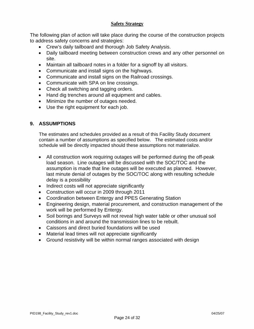
Safety Strategy
The following plan of action will take place during the course of the construction projects to address safety concerns and strategies:
• Crew’s daily tailboard and thorough Job Safety Analysis. • Daily tailboard meeting between construction crews and any other personnel on
site. • Maintain all tailboard notes in a folder for a signoff by all visitors. • Communicate and install signs on the highways. • Communicate and install signs on the Railroad crossings. • Communicate with SPA on line crossings. • Check all switching and tagging orders. • Hand dig trenches around all equipment and cables. • Minimize the number of outages needed. • Use the right equipment for each job.
9. ASSUMPTIONS
The estimates and schedules provided as a result of this Facility Study document contain a number of assumptions as specified below. The estimated costs and/or schedule will be directly impacted should these assumptions not materialize.
• All construction work requiring outages will be performed during the off-peak
load season. Line outages will be discussed with the SOC/TOC and the assumption is made that line outages will be executed as planned. However, last minute denial of outages by the SOC/TOC along with resulting schedule delay is a possibility
• Indirect costs will not appreciate significantly • Construction will occur in 2009 through 2011 • Coordination between Entergy and PPES Generating Station • Engineering design, material procurement, and construction management of the
work will be performed by Entergy. • Soil borings and Surveys will not reveal high water table or other unusual soil
conditions in and around the transmission lines to be rebuilt. • Caissons and direct buried foundations will be used • Material lead times will not appreciate significantly • Ground resistivity will be within normal ranges associated with design
PID198_Facility_Study_rev1.doc 04/25/07 Page 24 of 32
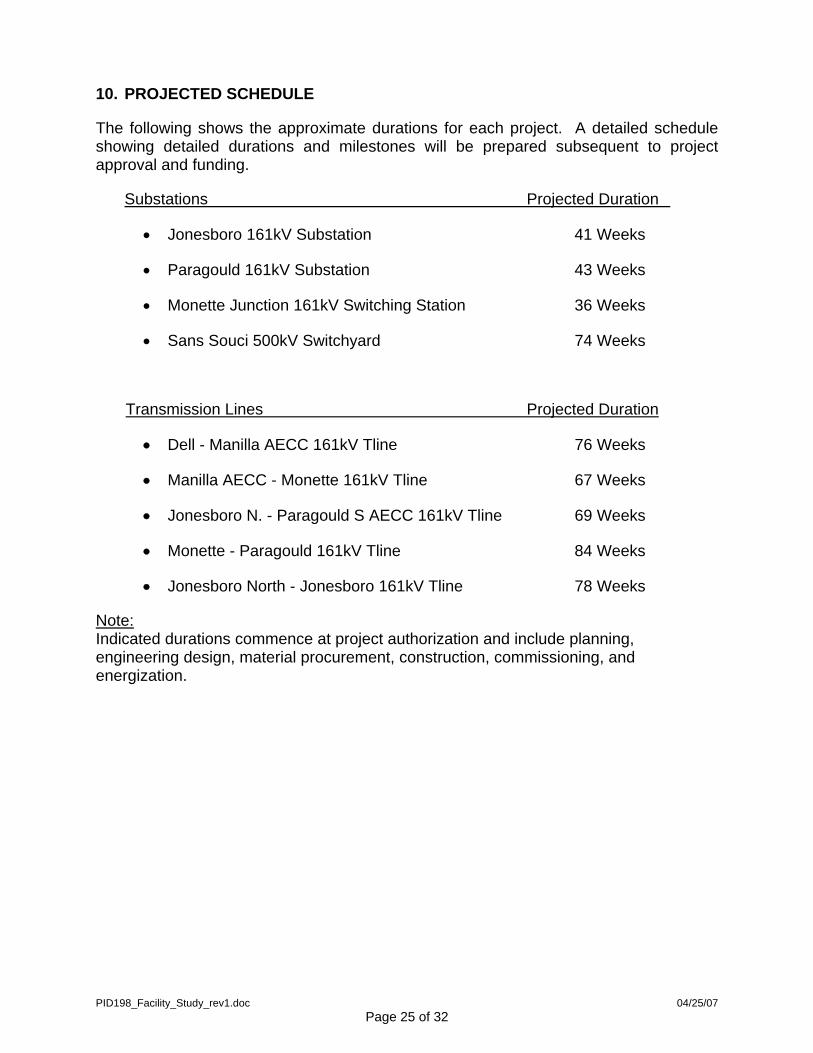
10. PROJECTED SCHEDULE
The following shows the approximate durations for each project. A detailed schedule showing detailed durations and milestones will be prepared subsequent to project approval and funding.
Substations Projected Duration
• Jonesboro 161kV Substation 41 Weeks
• Paragould 161kV Substation 43 Weeks
• Monette Junction 161kV Switching Station 36 Weeks
• Sans Souci 500kV Switchyard 74 Weeks
Transmission Lines Projected Duration
• Dell - Manilla AECC 161kV Tline 76 Weeks
• Manilla AECC - Monette 161kV Tline 67 Weeks
• Jonesboro N. - Paragould S AECC 161kV Tline 69 Weeks
• Monette - Paragould 161kV Tline 84 Weeks
• Jonesboro North - Jonesboro 161kV Tline 78 Weeks
Note: Indicated durations commence at project authorization and include planning, engineering design, material procurement, construction, commissioning, and energization.
PID198_Facility_Study_rev1.doc 04/25/07 Page 25 of 32
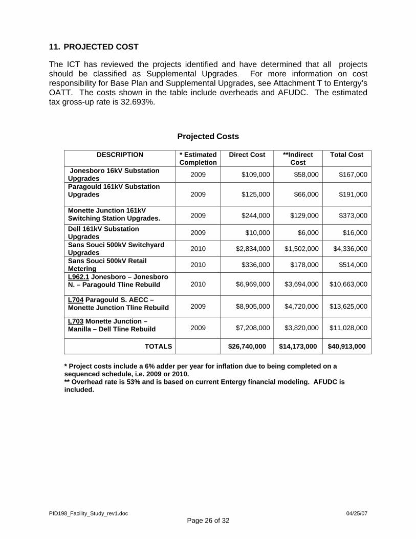
11. PROJECTED COST
The ICT has reviewed the projects identified and have determined that all projects should be classified as Supplemental Upgrades. For more information on cost responsibility for Base Plan and Supplemental Upgrades, see Attachment T to Entergy’s OATT. The costs shown in the table include overheads and AFUDC. The estimated tax gross-up rate is 32.693%.
Projected Costs
DESCRIPTION * Estimated Completion
Direct Cost **Indirect Cost
Total Cost
Jonesboro 16kV Substation Upgrades 2009 $109,000 $58,000 $167,000
Paragould 161kV Substation Upgrades
2009 $125,000 $66,000 $191,000
Monette Junction 161kV Switching Station Upgrades. 2009 $244,000 $129,000 $373,000
Dell 161kV Substation Upgrades 2009 $10,000 $6,000 $16,000
Sans Souci 500kV Switchyard Upgrades 2010 $2,834,000 $1,502,000 $4,336,000
Sans Souci 500kV Retail Metering 2010 $336,000 $178,000 $514,000
L962.1 Jonesboro – Jonesboro N. – Paragould Tline Rebuild 2010 $6,969,000 $3,694,000 $10,663,000
L704 Paragould S. AECC – Monette Junction Tline Rebuild 2009 $8,905,000 $4,720,000 $13,625,000
L703 Monette Junction – Manilla – Dell Tline Rebuild 2009 $7,208,000 $3,820,000 $11,028,000
TOTALS $26,740,000 $14,173,000 $40,913,000
* Project costs include a 6% adder per year for inflation due to being completed on a sequenced schedule, i.e. 2009 or 2010. ** Overhead rate is 53% and is based on current Entergy financial modeling. AFUDC is included.
PID198_Facility_Study_rev1.doc 04/25/07 Page 26 of 32
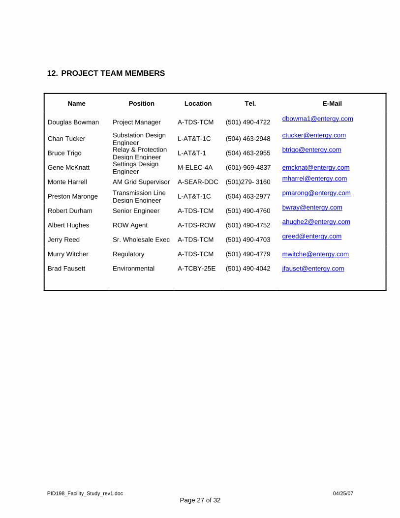
12. PROJECT TEAM MEMBERS
Name Position Location Tel. E-Mail
Douglas Bowman Project Manager A-TDS-TCM (501) 490-4722 [email protected]
Chan Tucker Substation Design Engineer L-AT&T-1C (504) 463-2948 [email protected]
Bruce Trigo Relay & Protection
Design Engineer L-AT&T-1 (504) 463-2955 [email protected]
Gene McKnatt Settings Design Engineer M-ELEC-4A (601)-969-4837 [email protected]
Monte Harrell AM Grid Supervisor A-SEAR-DDC (501)279- 3160 [email protected]
Preston Maronge Transmission Line Design Engineer L-AT&T-1C (504) 463-2977 [email protected]
Robert Durham Senior Engineer A-TDS-TCM (501) 490-4760 [email protected]
Albert Hughes ROW Agent A-TDS-ROW (501) 490-4752 [email protected]
Jerry Reed Sr. Wholesale Exec A-TDS-TCM (501) 490-4703 [email protected]
Murry Witcher Regulatory A-TDS-TCM (501) 490-4779 [email protected]
Brad Fausett Environmental A-TCBY-25E (501) 490-4042 [email protected]
PID198_Facility_Study_rev1.doc 04/25/07 Page 27 of 32
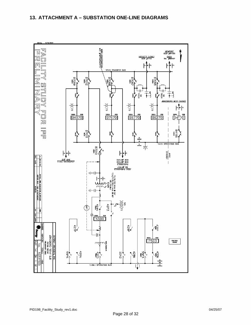
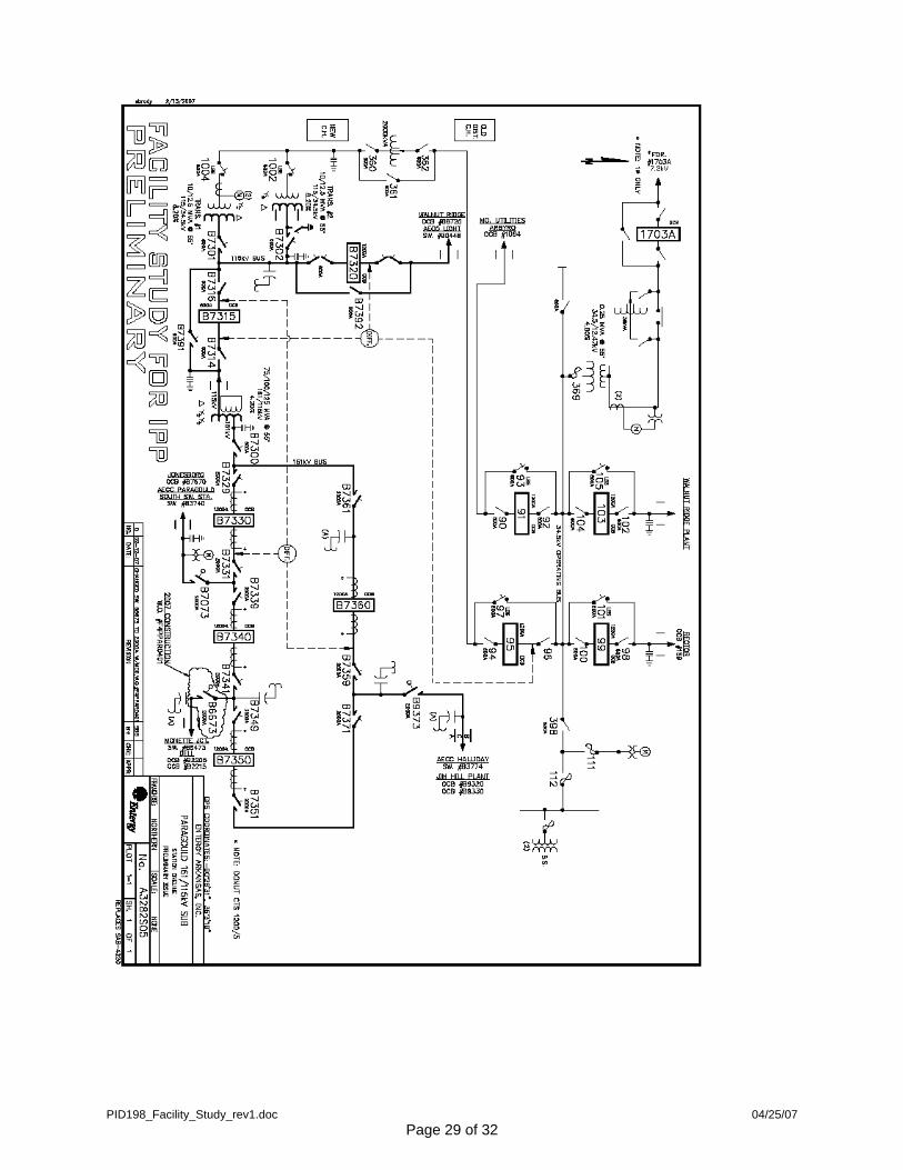
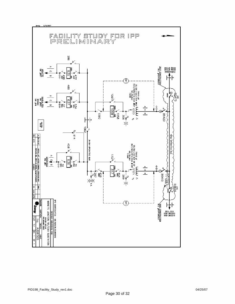
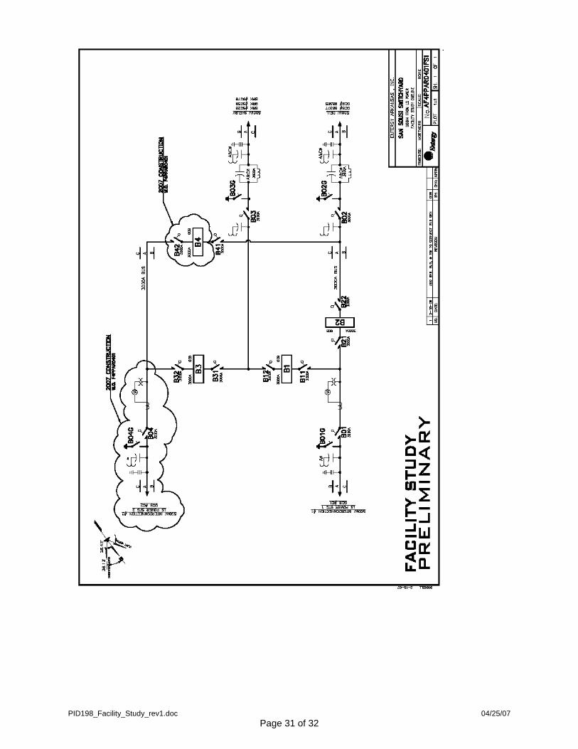
13. ATTACHMENT A – SUBSTATION ONE-LINE DIAGRAMS
PID198_Facility_Study_rev1.doc 04/25/07 Page 28 of 32
PID198_Facility_Study_rev1.doc 04/25/07 Page 29 of 32
PID198_Facility_Study_rev1.doc 04/25/07 Page 30 of 32
PID198_Facility_Study_rev1.doc 04/25/07 Page 31 of 32
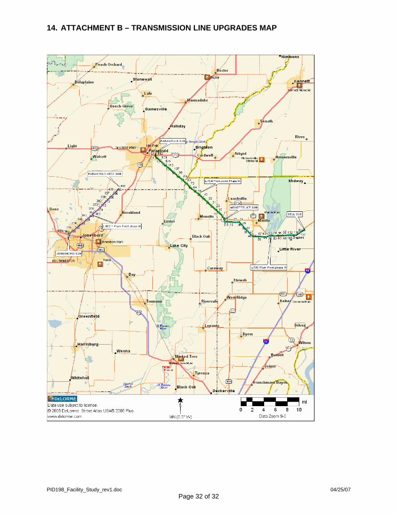
14. ATTACHMENT B – TRANSMISSION LINE UPGRADES MAP
PID198_Facility_Study_rev1.doc 04/25/07 Page 32 of 32