3. arithmetic for computers - mcmaster universityse2ga3/chapter 3.pdf · 3. arithmetic for...
TRANSCRIPT

3. Arithmetic for Computers Computer Architecture COMP SCI 2GA3 / SFWR ENG 2GA3
Emil Sekerinski, McMaster University, Fall Term 2015/16
"There are only 10 types of people in the world:those who understand binary and those who don't"

What Should the Instructor …
Start – Stop – Continue?
• Please write on the sheet.• You don’t need to put your name.• Sheets will be collected together with the quiz.
Summary of responses or individual responses will be shown in class and on Avenue.

Numbers with Fixed Width
Recall that words in memory are untyped:
• How to do arithmetic?
• How to identify errors like overflow?
• How does an Arithmetic Logic Unit (ALU) work?
bits (011011011100010 ....01)
instruction
R-format I-format ...
data
number text chars ..............
integer floating point
signed unsigned single precision double precision
... ... ... ...
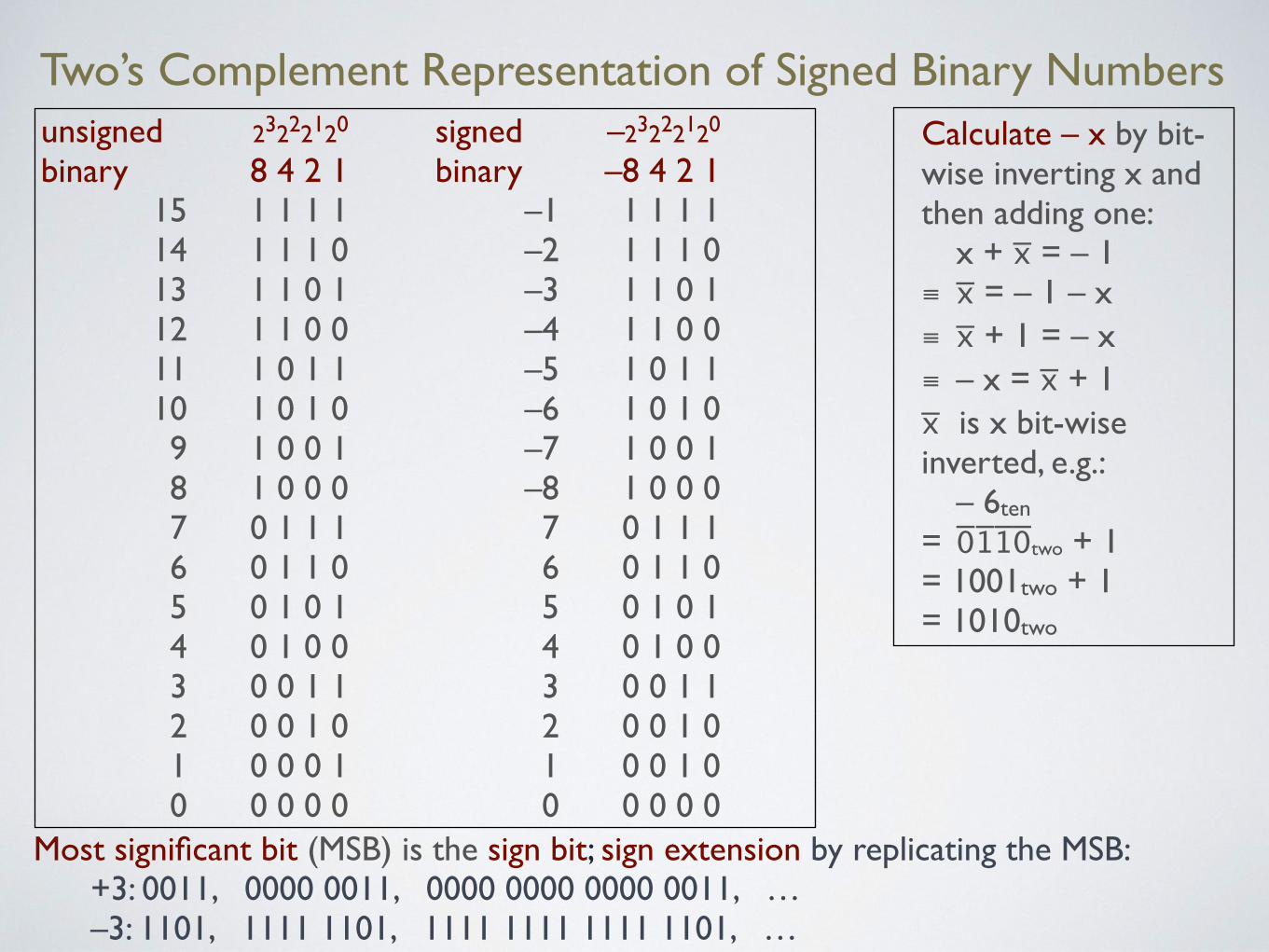
Two’s Complement Representation of Signed Binary Numbersunsigned 23222120 signed –23222120binary 8 4 2 1 binary –8 4 2 1
15 1 1 1 1 –1 1 1 1 1 14 1 1 1 0 –2 1 1 1 0 13 1 1 0 1 –3 1 1 0 1 12 1 1 0 0 –4 1 1 0 0 11 1 0 1 1 –5 1 0 1 1 10 1 0 1 0 –6 1 0 1 0 9 1 0 0 1 –7 1 0 0 1 8 1 0 0 0 –8 1 0 0 0 7 0 1 1 1 7 0 1 1 1 6 0 1 1 0 6 0 1 1 0 5 0 1 0 1 5 0 1 0 1 4 0 1 0 0 4 0 1 0 0 3 0 0 1 1 3 0 0 1 1 2 0 0 1 0 2 0 0 1 0 1 0 0 0 1 1 0 0 1 0 0 0 0 0 0 0 0 0 0 0
Most significant bit (MSB) is the sign bit; sign extension by replicating the MSB: +3: 0011, 0000 0011, 0000 0000 0000 0011, … –3: 1101, 1111 1101, 1111 1111 1111 1101, …
Calculate – x by bit-wise inverting x and then adding one:
x + x̅ = – 1 ≡ x̅ = – 1 – x ≡ x̅ + 1 = – x ≡ – x = x̅ + 1x̅ is x bit-wise inverted, e.g.:
– 6ten = 0̅11̅0̅̅two + 1 = 1001two + 1 = 1010two

Addition of Unsigned Numbers
8 4 2 1
2 0 0 1 0 + 3 0 0 1 1
8 4 2 1
3 0 0 1 1 + 5 0 1 0 1
8 4 2 1
11 1 0 1 1 + 7 0 1 1 1
Carries 0 1 0
5 0 1 0 1
Carries 1 1 1
8 1 0 0 0
Carries 1 1 1 1
? 0 1 1 0
Addition results in carry, overflow detected!

Addition of Two’s Complement Signed Numbers
– 8 4 2 1
2 0 0 1 0 + 3 0 0 1 1
– 8 4 2 1
3 0 0 1 1 + 5 0 1 0 1
– 8 4 2 1
– 5 1 0 1 1 + 7 0 1 1 1
Carries
Carries
Carries
Can we use the same procedure asfor unsigned number?A. Yes, same procedure appliesB. Yes, “same” procedure but with
different overflow detectionC. No, need new procedure to detect
overflowD. No, overflow cannot be detectedE. None of the above
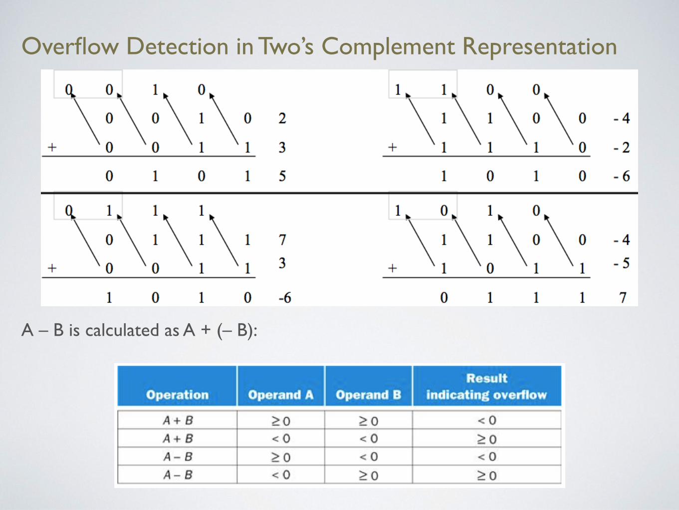
Overflow Detection in Two’s Complement Representation
A – B is calculated as A + (– B):

Dealing with Overflow
Some languages (e.g. C, Java) ignore overflow and use modulo arithmetic:
• A + B = (A ⊕ B) % 232 (% is modulo, ⊕ is mathematical addition)
• In MIPS, add unsigned (addu), add immediate unsigned (adiud), and subtract unsigned (addu) do not cause exceptions on overflow
Other languages (e.g. Ada, Fortran, Eiffel) use strict arithmetic and raise an exception:
• In MIPS, add (add), add immediate (addi), and subtract (sub) cause exceptions on overflow.
• On overflow, exception handler (interrupt handler) is invoked:
• save PC in exception program counter (EPC)
• jump to predefined handler address, e.g. as in Python
• mfc0 (move from coprocessor reg) instructioncan retrieve EPC value, to return after corrective action
try:x=A+Bexcept:...handler...
Saturating Arithmetic
Graphics and media processing operates on vectors of 8-bit and 16-bit data, e.g. colour channels
• Use 64-bit (128 bit, 256 bit, 512 bit) adder, with partitioned carry chain
• Operate on 8×8-bit, 4×16-bit, or 2×32-bit vectors
• SIMD (single-instruction, multiple-data)
Saturating operations
• On overflow, result is largest representable value
• E.g. clipping in audio, saturation in video

Why Two’s Complement Representation?
Other representations are possible:
• sign-magnitude: additional +/–
• one’s complement: – x = x̅
Two’s complement gives us:
• obvious representation of 0,1,2...
• single value of 0
• (almost) equal coverage of positive and negative numbers
• easy detection of sign
• easy negation
• easy implementation with logic gates

Logic Design
Electronics in modern computers is digital, distinguishing only high and low voltage. A signal that is true, or 1, is asserted, a signal that is false, or 0 is deasserted.
The Boolean algebra is used in designing circuits:
• Disjunction (OR operator): A ∨ B, A + B
• Conjunction (AND operator): A ∧ B, A·• B
• Negation (NOT operator): ¬A, A̅
We use the notation common in circuit design. Some laws of Boolean algebra:
• Identity law: A + 0 = A and A • 1 = A
• Zero and One laws: A + 1 = 1 and A • 0 = 0
• Inverse laws: A + A̅ = 1and A • A̅ = 0
• Commutative laws: A + B = B + A and A • B = B • A
• Associative laws: A + (B + C) = (A + B) + C and A • (B • C) = (A • B) • C
• Distributive laws: A· (B + C) = (A • B) + (A • C) and A + (B • C) = (A + B) • (A + C)
• DeMorgan’s laws, …
Gates
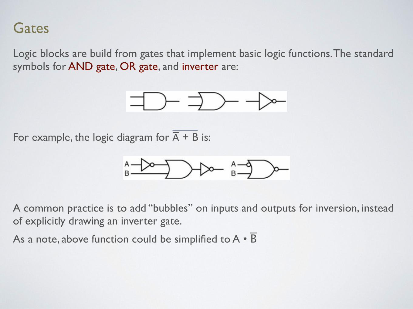
Logic blocks are build from gates that implement basic logic functions. The standard symbols for AND gate, OR gate, and inverter are:
For example, the logic diagram for A̅ + B is:
A common practice is to add “bubbles” on inputs and outputs for inversion, instead of explicitly drawing an inverter gate.
As a note, above function could be simplified to A • B ̅

A 1-Bit Adder
A full adder or (3, 2) adder as it has 3 inputs and2 outputs, in contrast to a half adder or (2, 2) adder with only 2 inputs:

Implementing a 1-Bit Adder
From the table, we see that:
CarryOut = (b • CarryIn) + (a • CarryIn ) + (a • b)
We also have that Sum is 1 if an odd number of inputs is 1 (CI abbreviates CarryIn):
Sum = (a • b ̅• C̅ I)̅ + (a ̅• b • C̅ I)̅ + (a ̅• b ̅• CI) + (a • b • CI)

Multiplexor
A multiplexor, or selector, takes several data values and a selector or control value. For data A, B and selector S, it computes C = (A • S) + (B • S)̅. As it is common, we use a dedicated symbol:
In general, there can be more than two data inputs. For n data inputs, log n selector inputs are needed. In this case, first a decoder takes the selector input and generates n signals.
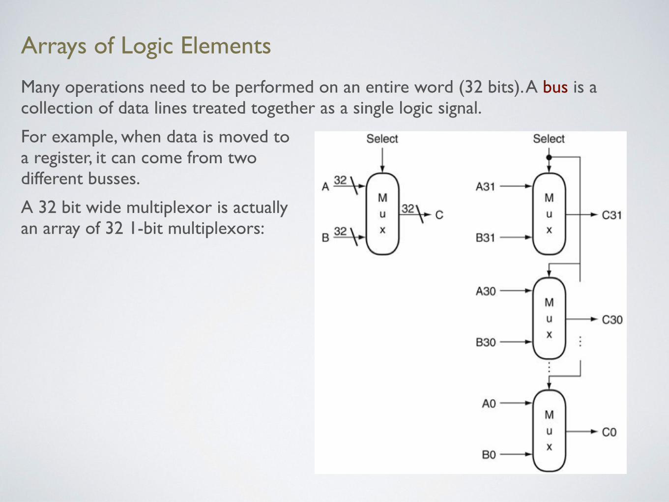
Arrays of Logic Elements
Many operations need to be performed on an entire word (32 bits). A bus is a collection of data lines treated together as a single logic signal.
For example, when data is moved toa register, it can come from twodifferent busses.
A 32 bit wide multiplexor is actually an array of 32 1-bit multiplexors:

Constructing an ALU
The arithmetic logic unit (ALU) isthe brawn of the computer.
The operation is controlled throughthe ALU Control Lines:
• 000 and
• 001 or
• 010 add
• 110 subtract
• 111 set-on-less-than
These ALU Control Lines are obtainedfrom the corresponding bits of theinstructions.

A 1-Bit ALU
This 1-bit ALU can perform AND, OR, ADD

A 32-Bit ALU
1-bit ALU 32-bit ALU
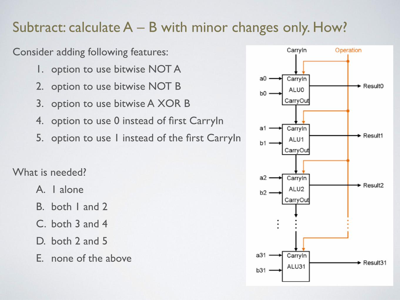
Subtract: calculate A – B with minor changes only. How?
Consider adding following features:
1. option to use bitwise NOT A
2. option to use bitwise NOT B
3. option to use bitwise A XOR B
4. option to use 0 instead of first CarryIn
5. option to use 1 instead of the first CarryIn
What is needed?
A. 1 alone
B. both 1 and 2
C. both 3 and 4
D. both 2 and 5
E. none of the above
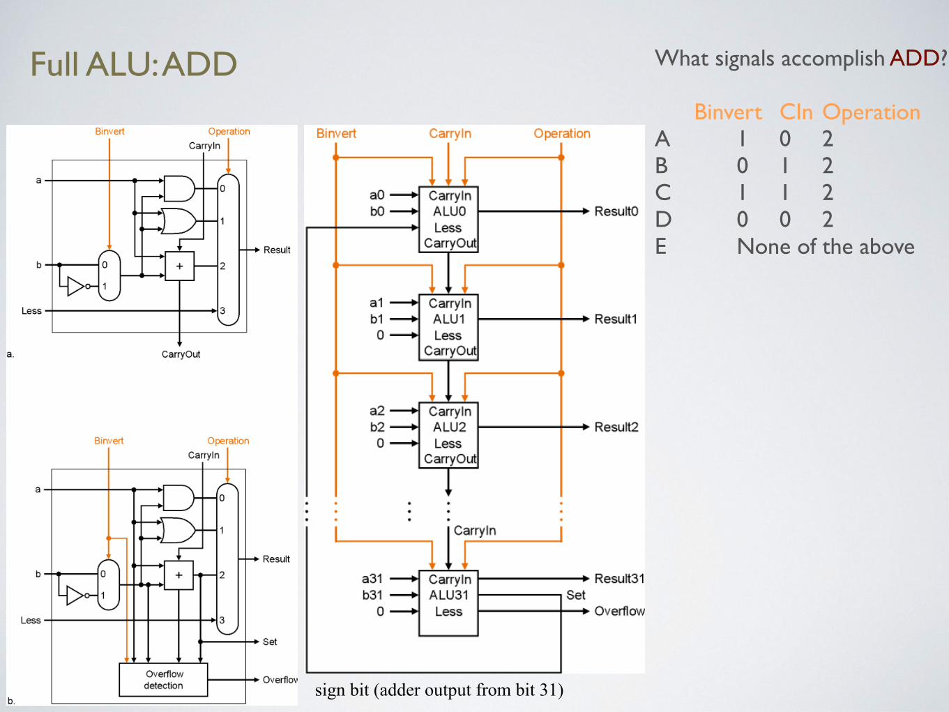
Full ALU: ADD What signals accomplish ADD?
Binvert CIn Operation A 1 0 2 B 0 1 2 C 1 1 2 D 0 0 2 E None of the above
sign bit (adder output from bit 31)

Full ALU: OR What signals accomplish OR?
Binvert CIn Operation A 1 0 0 B 0 1 1 C 1 1 1 D 1 0 1 E None of the above
sign bit (adder output from bit 31)

Full ALU: SUB What signals accomplish SUB?
Binvert CIn Operation A 1 0 2 B 0 1 2 C 1 1 2 D 0 0 2 E None of the above
sign bit (adder output from bit 31)

Full ALU: SLT What signals accomplish SLT?
Binvert CIn Operation A 1 0 2B 0 1 2C 1 1 3D 0 0 3E None of the above
Recall: slt$t0,$t1,$t2
meansif($t1<$t2)$t0=1else$t0=0
Assume A in $t1, B in $t2
sign bit (adder output from bit 31)

Full ALU: Practice What signals accomplish:
Binvert CIn Operation add sub and or beq slt
sign bit (adder output from bit 31)

Disadvantage of Ripple Carry Adder
• The carry bit may have to propagate from LSB to MSB
• Worst case delay for N bit adder: 2N gate delays
• Faster schemes accelerate the movement of the carry, but need more gates

Long Multiplication
1000 × 1001 1000 0000 0000 1000 01001000
multiplicand
multiplier
product
Length of product is sum of lengths of operands

Multiplication Hardware
initially 0
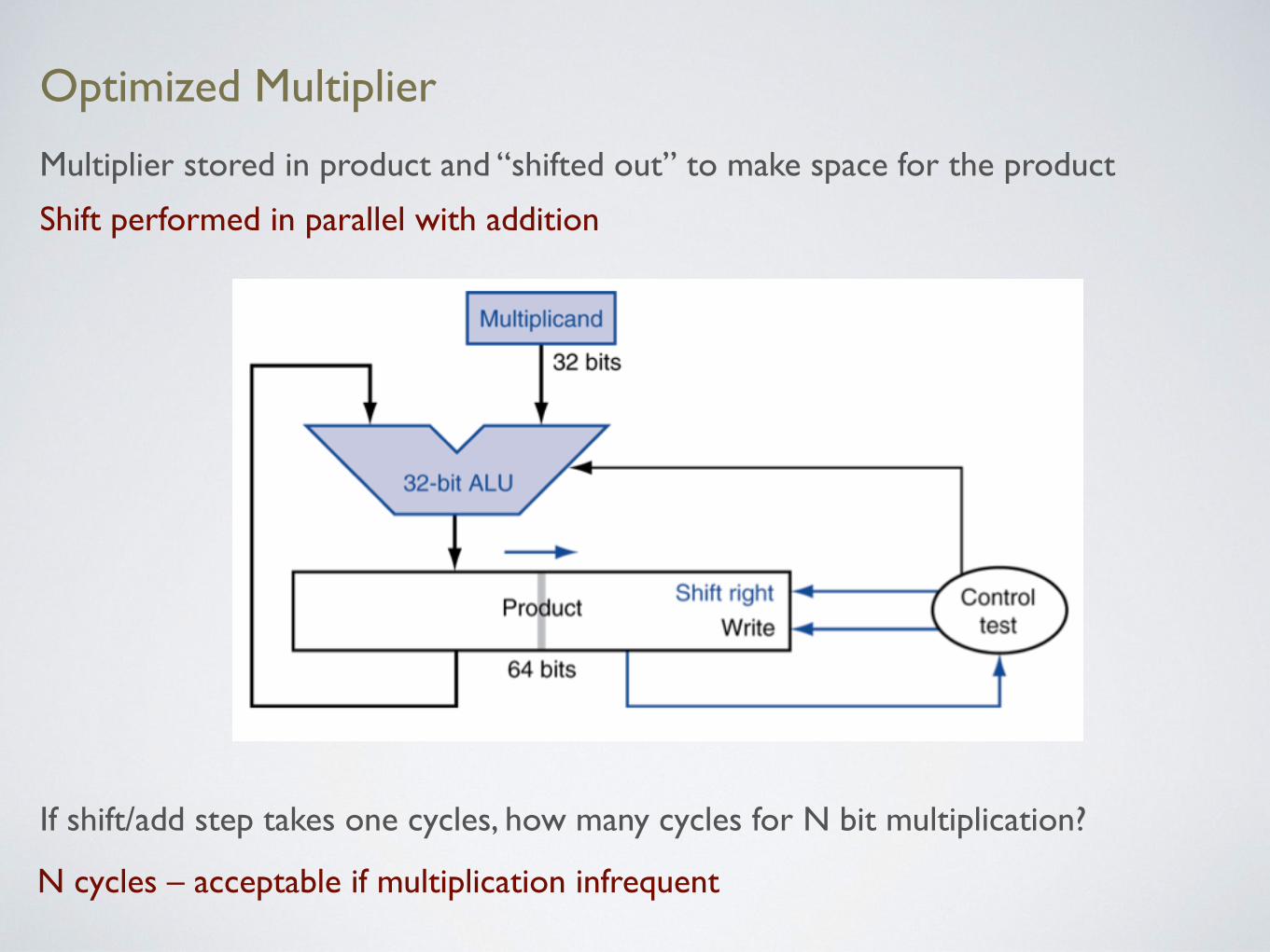
Optimized Multiplier
Multiplier stored in product and “shifted out” to make space for the product
Shift performed in parallel with addition
If shift/add step takes one cycles, how many cycles for N bit multiplication?
N cycles – acceptable if multiplication infrequent

Faster Multiplier
Multiplications of the multiplicand by 0 or 1 of the multiplier can be done in parallel
Multiple adders are used to sum up in parallel
How many cycles are needed for N bits? How many adders are needed for N bits?
For N bits, log2 N cycles (5 for 32 bits) and N – 1 adders (31 for 32 bits) Multiplications can be pipelined

MIPS Multiplication and Division
Two 32-bit registers for product
• HI: most-significant 32-bits of product / 32-bit remainder of division
• LO: least-significant 32-bits of product / 32-bit quotient of division
Instructions
• mult rs, rt / multu rs, rt 64-bit product in HI/LO
• mfhi rd / mflo rdMove from HI/LO to rd Can test HI value to see if product overflows 32 bits
• mul rd, rs, rt Least-significant 32 bits of product → rd
• div rs, rt / divu rs, rt 32-bit remainder in HI, 32-bit quotient in LO No divide-by-0 checking, must be performed explicitly
Integer Multiplication and Division Summary
Multiplication of two’s complement integers uses the same algorithm as for unsigned integers
Division has similar structure to multiplication, same hardware can be used
Quotient and remainder of division can be computed at the same time at no extra cost, c.f. q,r=divmod(x,y) in Python, compiler optimization
Computing the carry bit faster and multiplying faster are examples when for trading number of gates with speed.

Floating Point
Representation for non-integral numbers, including very small and very large
Like scientific notation
• –2.34 × 1056
• +0.002 × 10⁻⁴
• +987.02 × 10⁹
In binary
• ±1.xxxxxxxtwo × 2yyyy
Types float (single precision) and double (double precision) in C, type float (double precision) in Python
Defined by IEEE Std 754-1985, in response to divergence of representations
Two representations
• single precision: 32-bit
• double precision: 64-bit
normalized
not normalized
not normalized
significand exponent

IEEE Floating Point Format
Sign bit S: 0 → non-negative, 1 → negative
Normalized significand: 1.0 ≤ significand < 2.0
• always leading pre-binary-point 1 bit, no need to represent
• significand is fraction with “1.” restored
Unsigned exponent: actual exponent = exponent – bias
• single precision: bias = 127
• double precision: bias = 1203
S Exponent Fraction
single precision: 8 bits 23 bitsdouble precision: 11 bits 52 bits
x = (-1)S × (1+Fraction) × 2(Exponent–Bias)

Convert Floating-Point Number
What is 1100 0001 0010 0000 0000 0000 0000 0000 ?
A. – 1.010 x 2130
B. – 10
C. + 10
D. + 1.010 x 2130
E. None of the above
S Exponent Fraction
single precision: 8 bits 23 bits
x = (-1)S × (1+Fraction) × 2(Exponent–Bias)

Floating-Point Addition: Decimal
Consider a 4-digit decimal example
9.999 × 101 + 1.610 × 10⁻¹
1. Align decimal points: shift number with smaller exponent
9.999 × 101 + 0.016 × 101
2. Add significands
9.999 × 101 + 0.016 × 101 = 10.015 × 101
3. Normalize result & check for over/underflow
1.0015 × 10²
4. Round and renormalize if necessary
1.002 × 10²

Floating-Point Addition: Binary
Now consider a 4-digit binary example
1.0002 × 2–1 + –1.1102 × 2–2 = 0.5 + –0.4375
1. Align binary points: shift number with smaller exponent
1.0002 × 2–1 + –0.1112 × 2–1
2. Add significands
0.0012 × 2–1
3. Normalize result & check for over/underflow
1.0002 × 2–4, no over/underflow
4. Round and renormalize if necessary
1.0002 × 2–4 (no change) = 0.0625

Floating-Point Adder Hardware
Step 1
Step 2
Step 3
Step 4

Floating-Point Hardware
Floating-point adder much more complex than integer adder:
• Doing it in one clock cycle would take too long
• Slower clock would penalize all instructions
FP multiplier is of similar complexity to FP adder
• But uses a multiplier for significands instead of an adder
FP arithmetic hardware usually does
• Addition, subtraction, multiplication, division, reciprocal, square-root
• FP ↔ integer conversion
Operations usually takes several cycles, but can be pipelined

Floating-Point Instructions in MIPS
FP hardware is coprocessor 1: adjunct processor that extends the ISA with separate FP registers
• 32 single-precision: $f0, $f1, … $f31, paired for double-precision: $f0/$f1, $f2/$f3, …
• Release 2 of MIPS ISA supports 32 × 64-bit FP reg’s
• FP instructions operate only on FP registers
• More registers with minimal code-size impact
FP load and store instructions: lwc1, ldc1, swc1, sdc1
ldc1$f8,32($sp)
Single-precision arithmetic: add.s, sub.s, mul.s, div.s
add.s$f0,$f1,$f6
Double-precision arithmetic: add.d, sub.d, mul.d, div.d
mul.d$f4,$f4,$f6
Comparison: c.xx.s, c.xx.d (xx is eq, lt, le, …), sets or clears FP condition-code bit
c.lt.s$f3,$f4
Branch on FP condition code true or false: bc1t, bc1f
bc1tTargetLabel
Floating-Point Example: °F to °C
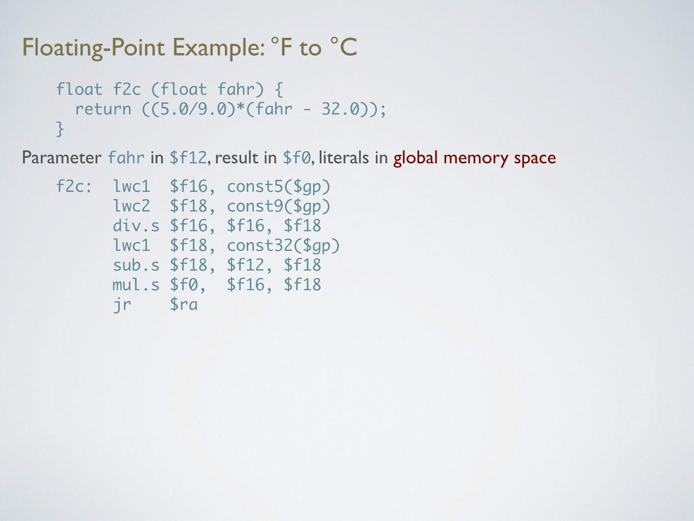
floatf2c(floatfahr){return((5.0/9.0)*(fahr-32.0));}
Parameter fahr in $f12, result in $f0, literals in global memory space
f2c: lwc1$f16,const5($gp) lwc2$f18,const9($gp) div.s$f16,$f16,$f18 lwc1$f18,const32($gp) sub.s$f18,$f12,$f18 mul.s$f0,$f16,$f18 jr$ra