3. automatic generation of java code from uml diagrams using ujector · international journal of...
TRANSCRIPT
International Journal of Software Engineering and Its Applications
Vol.3, No.2, April, 2009
21
Automatic Generation of Java Code from UML Diagrams using UJECTOR
Muhammad Usman, and Aamer Nadeem Center for Software Dependability
Mohammad Ali Jinnah University, Islamabad, Pakistan [email protected], [email protected]
Abstract
In recent years, the significance of automated generation of object-oriented code from UML diagrams has increased due to its benefits, such as, cost reduction and accuracy. Consistency Checking between UML diagrams, and ensuring accuracy, maintainability, efficiency, and completeness of the generated code are the main concerns in this area. This paper extends our work on a tool called UJECTOR for automatic generation of executable Java code from UML diagrams. A set of three UML diagrams, i.e., class diagram, sequence diagrams and activity diagrams are input to the tool to generate completely executable Java code automatically. The object-oriented code structure is built from class diagram, methods’ flow of control is created through sequence diagrams, and object manipulations are included by activity diagrams from the implemented approach in UJECTOR. The extension includes a more detailed overview of the code generation tool regarding its architecture and code generation process. Two detailed case studies are presented to validate the generated code from the code generation tool. We also compare UJECTOR with the existing research-based, commercial and open-source tools. The evaluation results show that the generated code from UJECTOR is fully functional and understandable. 1. Introduction
The Unified Modeling Language (UML) [1] has now become the de-facto industry standard for object-oriented (OO) software development. UML provides a set of diagrams to model structural and behavioral aspects of an object-oriented system [2, 3]. The UML diagrams created in the design phase to model an object-oriented system are later used in the implementation phase [4]. UML diagrams are powerful enough to hold most of the implementation details. However, manual translation of UML diagrams into object-oriented code does not guarantee conformance of the code with the UML diagrams due to the possibility of occurrence of human errors. Automatic translation of UML diagrams to object-oriented code is highly desirable because it eliminates the chances of introduction of human errors in the translation process. Automatic code generation is efficient which, in turn, helps the software engineers deliver the software on time. Realizing the potential of automated code generation, in recent years, the Object Management Group (OMG) introduced Model Driven Architecture (MDA) [5] which supports automated translation of diagrams into code.
In this paper, we extend our work in [6] on UJECTOR (UML to Java Executable Code generaTOR) which generates executable Java code from UML 2.0 class, sequence, and activity diagrams. The paper provides deep overview of our tool’s implementation. UJECTOR is developed to implement our proposed code generation approach in [7]. It integrates both structural and behavioral features of an OO application. UML class diagram is used to generate code skeleton while UML sequence diagram adds behavior in generated
International Journal of Software Engineering and Its Applications
Vol.3, No.2, April, 2009
22
skeleton. UML activity diagrams are used to provide code completeness and user interactions. Activity diagrams are referenced in sequence diagrams. Actions from UML superstructure [8] are used in activity diagrams.
We have applied our proposed work on two real-life example, i.e., Point-of-Sale and University system. The developed code generation tool is used to generate code for both the case studies to experimentally validate the generated code. The results show that the generated code is consistent with the input UML diagrams. The generated code is fully functional, and understandable. The simplicity of the generated Java code is ensured by the use of UML class and sequence diagrams. UML activity diagram actions incorporate fully functional features in the generated code which include object manipulations and user interactions. We have also compared UJECTOR with the existing research-based, commercial, and open-source UML code generators. We conclude that the code generated by UJECTOR is more thorough and understandable than the other tools.
The rest of this paper is structured as follows: section 2 presents the code generation tools developed to implement existing approaches. Section 3 provides a brief overview of our code generation tool architecture. Section 4 describes the process flow of our tool implementing the code generation approach in [7]. Section 5 discusses real-life case studies, i.e., Point-of-Sale and University system, and also presents a demonstration of the generated code from Point-of-Sale case study. Section 6 compares generated code results from real-life example with available UML code generation tools. Section 7 concludes the paper. 2. Related Work
In this section, we discuss the existing tools to automatically generate the code from UML diagrams. 2.1. OCode
OCode was developed by Ali and Tanaka [9] to generate Java code from UML state diagram. The tool takes state diagram represented in Design Schema List language (DSL) as an input. It consists of two components known as interpreter and code generator. The interpreter generates a transition table from the DSL while code generator generates Java code from the transition table. 2.2. JCode
JCode was implemented by Niaz and Tanaka [10] to generate Java code from UML statechart. The tool takes statechart represented in DSL as an input. The tool consists of three components known as interpreter, transformer and code generator. The interpreter takes DSL as an input and generates intermediate transition table. The transformer generates transformed transition table from the intermediate transition table. The transformer focuses on resolving concepts like state hierarchy, state composition, compound transition, etc in the intermediate transition table. The transformed transition table is used as an input to the code generator to generate Java code. 2.3. Rhapsody
International Journal of Software Engineering and Its Applications
Vol.3, No.2, April, 2009
23
Rhapsody was developed by Harel and Gery [11] to generate C++ code from UML object and statechart diagrams. It also takes message sequence charts (MSC) as an additional input. The tool takes STATEMATE representation of statechart as an input and generates C++ code. 2.4. dCode
dCode was created by Ali and Tanaka [12] to generate Java code from UML object, activity and statechart diagrams. The tool follows the same code generation process as described for OCode [9].
From an analysis of the existing code generation tools from UML diagrams, we conclude that:
The completeness of the generated code is a big issue which includes complete flow of control for each method, object manipulations, and user interactions. Although all the tools include flow of control in the generated code but object manipulations are ignored.
The generated code lacks object manipulation which reflects that the class methods in the generated code are not completely implemented because object manipulation ensure variable creations, their values updating, etc, which are very important in the complete implementation of a class method.
The generated code lacks user interaction which means that the user cannot input any object value to the application. The user also does not have the facility to know about the current state of the system. When user interactions are missing then the generated code would always execute on a single set of variables’ value.
The existing work lacks understandability in the generated code. Although Rhapsody and dCode use UML structural diagrams for creating structure but the generated code structure from nearly all the tools does not fully conforms the input UML diagrams which leads to problems during code maintenance phase.
All the UML based code generation tools use older versions of UML in code generation process rather than UML 2.x. UML 2.x introduces new diagrams and features for complete OO application designing which help in completeness of the generated code.
3. Tool Architecture
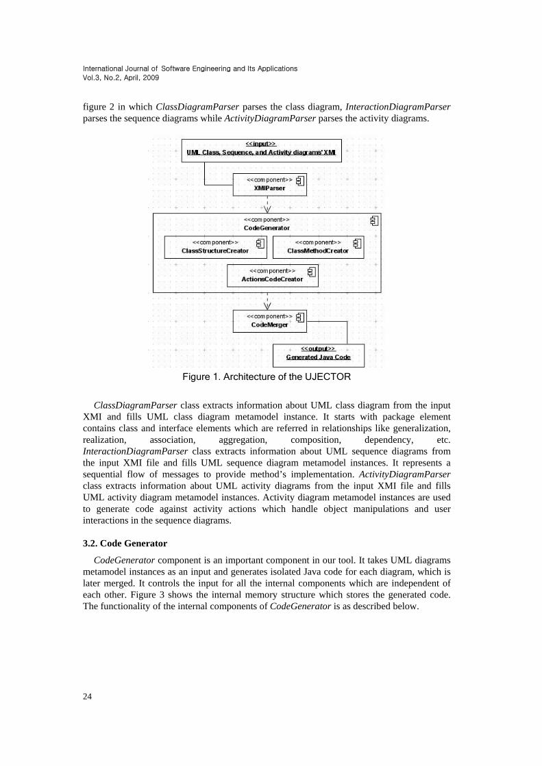
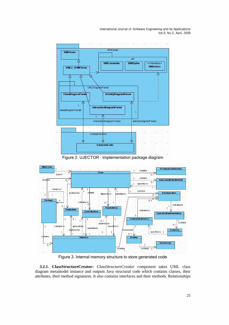
Figure 1 presents the overall architecture of the UJECTOR tool which implements the code generation approach described in [7]. The architecture of UJECTOR has three main components known as XMIParser, CodeGenerator, and CodeMerger. CodeGenerator is the main component responsible for generating Java code. ActionsCodeCreator, ClassMethodCreator, and ClassStructureCreator are the internal components of the CodeGenerator component. 3.1. XMIParser
XMIParser initiates the execution of our tool. It takes UML diagrams in XMI format [13] as input and generates UML diagrams metamodel instances [8]. The input consists of UML class, sequence and activity diagrams. The internal components of XMIParser are shown in
International Journal of Software Engineering and Its Applications
Vol.3, No.2, April, 2009
24
figure 2 in which ClassDiagramParser parses the class diagram, InteractionDiagramParser parses the sequence diagrams while ActivityDiagramParser parses the activity diagrams.
Figure 1. Architecture of the UJECTOR
ClassDiagramParser class extracts information about UML class diagram from the input XMI and fills UML class diagram metamodel instance. It starts with package element contains class and interface elements which are referred in relationships like generalization, realization, association, aggregation, composition, dependency, etc. InteractionDiagramParser class extracts information about UML sequence diagrams from the input XMI file and fills UML sequence diagram metamodel instances. It represents a sequential flow of messages to provide method’s implementation. ActivityDiagramParser class extracts information about UML activity diagrams from the input XMI file and fills UML activity diagram metamodel instances. Activity diagram metamodel instances are used to generate code against activity actions which handle object manipulations and user interactions in the sequence diagrams. 3.2. Code Generator
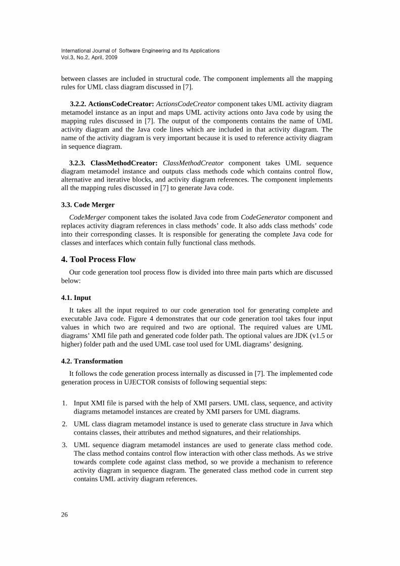
CodeGenerator component is an important component in our tool. It takes UML diagrams metamodel instances as an input and generates isolated Java code for each diagram, which is later merged. It controls the input for all the internal components which are independent of each other. Figure 3 shows the internal memory structure which stores the generated code. The functionality of the internal components of CodeGenerator is as described below.
International Journal of Software Engineering and Its Applications
Vol.3, No.2, April, 2009
25
Figure 2. UJECTOR – Implementation package diagram
Figure 3. Internal memory structure to store generated code
3.2.1. ClassStructureCreator: ClassStructureCreator component takes UML class
diagram metamodel instance and outputs Java structural code which contains classes, their attributes, their method signatures. It also contains interfaces and their methods. Relationships
International Journal of Software Engineering and Its Applications
Vol.3, No.2, April, 2009
26
between classes are included in structural code. The component implements all the mapping rules for UML class diagram discussed in [7].
3.2.2. ActionsCodeCreator: ActionsCodeCreator component takes UML activity diagram
metamodel instance as an input and maps UML activity actions onto Java code by using the mapping rules discussed in [7]. The output of the components contains the name of UML activity diagram and the Java code lines which are included in that activity diagram. The name of the activity diagram is very important because it is used to reference activity diagram in sequence diagram.
3.2.3. ClassMethodCreator: ClassMethodCreator component takes UML sequence
diagram metamodel instance and outputs class methods code which contains control flow, alternative and iterative blocks, and activity diagram references. The component implements all the mapping rules discussed in [7] to generate Java code. 3.3. Code Merger
CodeMerger component takes the isolated Java code from CodeGenerator component and replaces activity diagram references in class methods’ code. It also adds class methods’ code into their corresponding classes. It is responsible for generating the complete Java code for classes and interfaces which contain fully functional class methods. 4. Tool Process Flow
Our code generation tool process flow is divided into three main parts which are discussed below: 4.1. Input
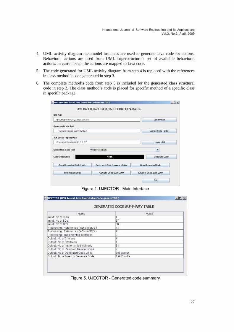
It takes all the input required to our code generation tool for generating complete and executable Java code. Figure 4 demonstrates that our code generation tool takes four input values in which two are required and two are optional. The required values are UML diagrams’ XMI file path and generated code folder path. The optional values are JDK (v1.5 or higher) folder path and the used UML case tool used for UML diagrams’ designing. 4.2. Transformation
It follows the code generation process internally as discussed in [7]. The implemented code generation process in UJECTOR consists of following sequential steps:
1. Input XMI file is parsed with the help of XMI parsers. UML class, sequence, and activity diagrams metamodel instances are created by XMI parsers for UML diagrams.
2. UML class diagram metamodel instance is used to generate class structure in Java which contains classes, their attributes and method signatures, and their relationships.
3. UML sequence diagram metamodel instances are used to generate class method code. The class method contains control flow interaction with other class methods. As we strive towards complete code against class method, so we provide a mechanism to reference activity diagram in sequence diagram. The generated class method code in current step contains UML activity diagram references.
International Journal of Software Engineering and Its Applications
Vol.3, No.2, April, 2009
27
4. UML activity diagram metamodel instances are used to generate Java code for actions. Behavioral actions are used from UML superstructure’s set of available behavioral actions. In current step, the actions are mapped to Java code.
5. The code generated for UML activity diagram from step 4 is replaced with the references in class method’s code generated in step 3.
6. The complete method’s code from step 5 is included for the generated class structural code in step 2. The class method’s code is placed for specific method of a specific class in specific package.
Figure 4. UJECTOR – Main Interface
Figure 5. UJECTOR – Generated code summary
International Journal of Software Engineering and Its Applications
Vol.3, No.2, April, 2009
28
Figure 6. UJECTOR – View generated code
4.3. Output
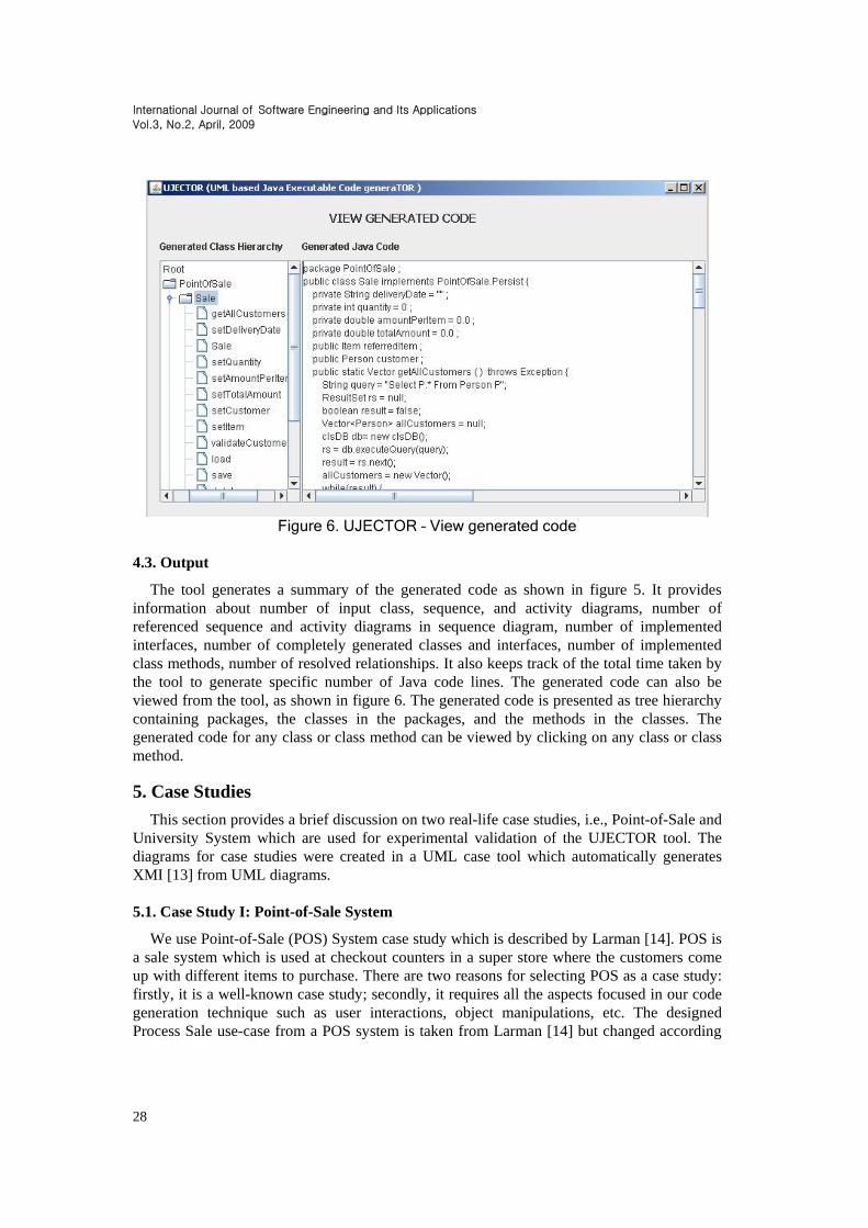
The tool generates a summary of the generated code as shown in figure 5. It provides information about number of input class, sequence, and activity diagrams, number of referenced sequence and activity diagrams in sequence diagram, number of implemented interfaces, number of completely generated classes and interfaces, number of implemented class methods, number of resolved relationships. It also keeps track of the total time taken by the tool to generate specific number of Java code lines. The generated code can also be viewed from the tool, as shown in figure 6. The generated code is presented as tree hierarchy containing packages, the classes in the packages, and the methods in the classes. The generated code for any class or class method can be viewed by clicking on any class or class method. 5. Case Studies
This section provides a brief discussion on two real-life case studies, i.e., Point-of-Sale and University System which are used for experimental validation of the UJECTOR tool. The diagrams for case studies were created in a UML case tool which automatically generates XMI [13] from UML diagrams. 5.1. Case Study I: Point-of-Sale System
We use Point-of-Sale (POS) System case study which is described by Larman [14]. POS is a sale system which is used at checkout counters in a super store where the customers come up with different items to purchase. There are two reasons for selecting POS as a case study: firstly, it is a well-known case study; secondly, it requires all the aspects focused in our code generation technique such as user interactions, object manipulations, etc. The designed Process Sale use-case from a POS system is taken from Larman [14] but changed according
International Journal of Software Engineering and Its Applications
Vol.3, No.2, April, 2009
29
to our requirements. The set of UML diagrams consists of one UML class diagram, thirty-seven UML sequence diagrams, and sixty UML activity diagrams. The Process Sale use-case is specified as customer comes to a shop counter with some selected items from a shop. The cashier initiates a new sale. The cashier checks whether the customer is new or already existing. In the case of an existing customer, the customer record is retrieved from the system. A list of items is included in a new sale against a specific customer. Finally, a receipt is generated and the sale is saved in the database.
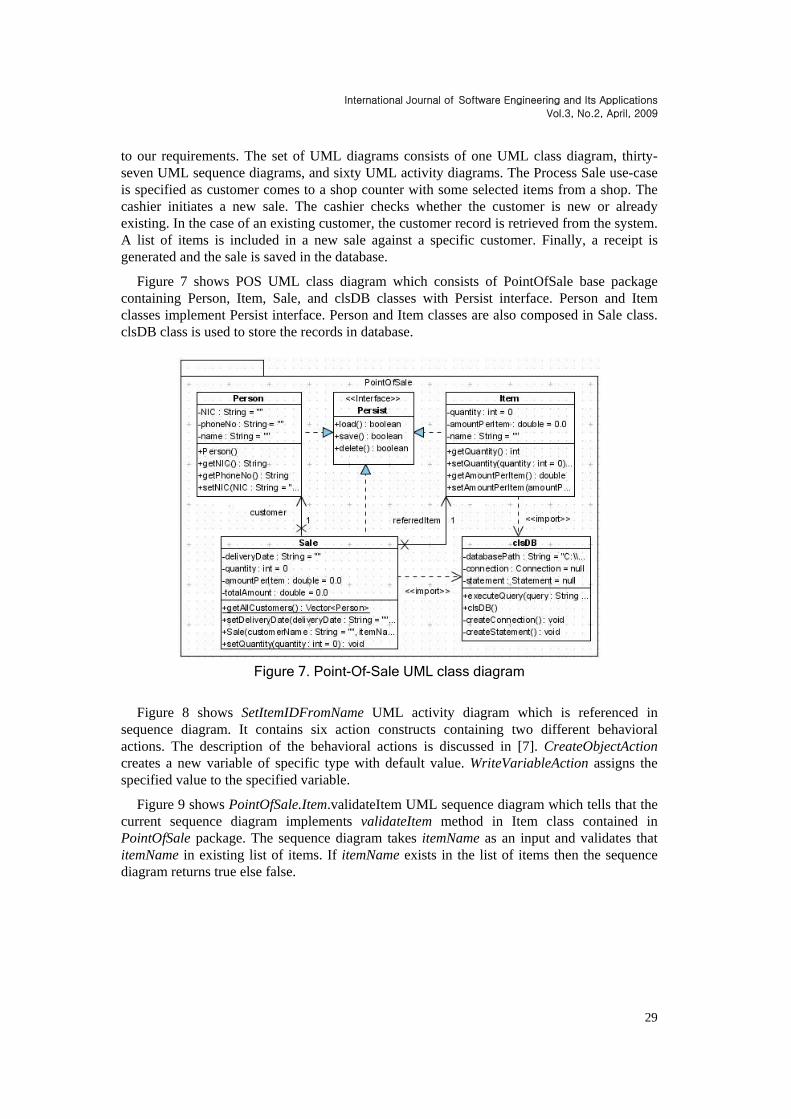
Figure 7 shows POS UML class diagram which consists of PointOfSale base package containing Person, Item, Sale, and clsDB classes with Persist interface. Person and Item classes implement Persist interface. Person and Item classes are also composed in Sale class. clsDB class is used to store the records in database.
Figure 7. Point-Of-Sale UML class diagram
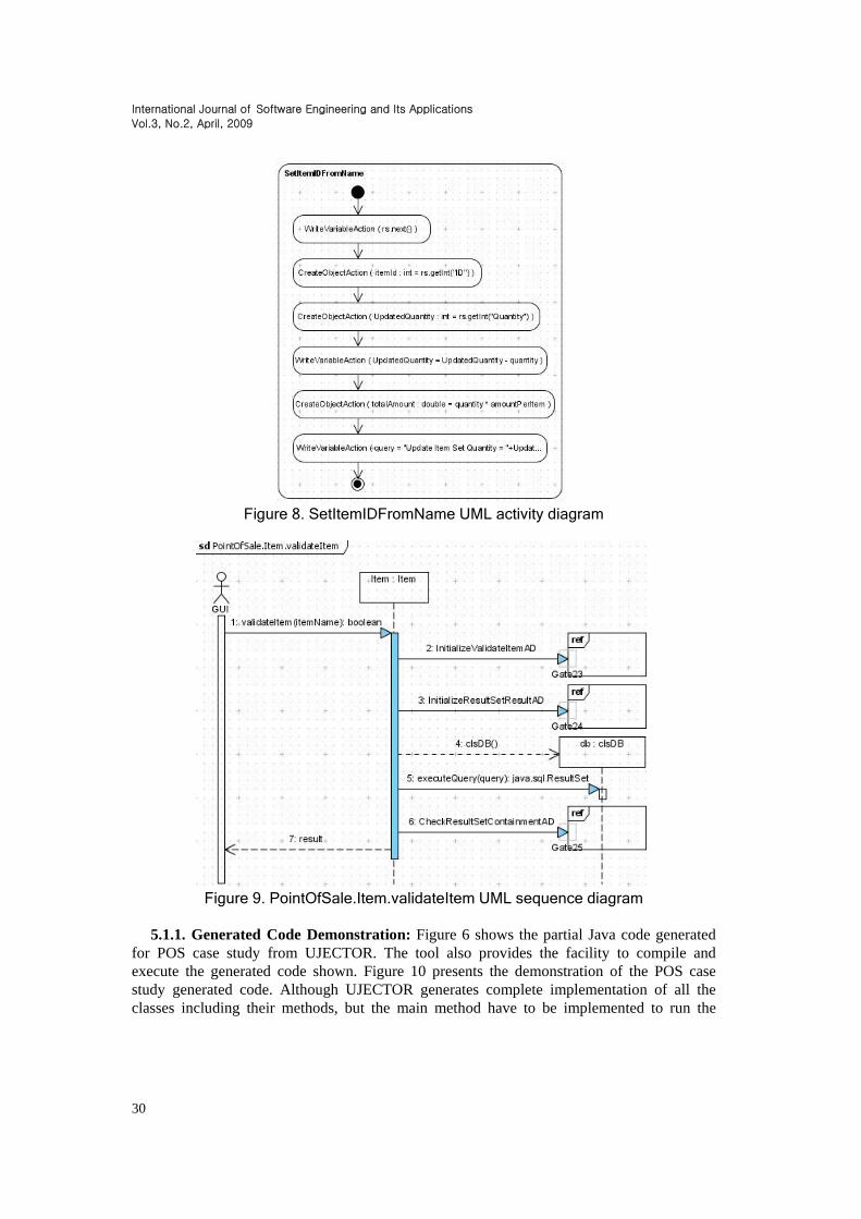
Figure 8 shows SetItemIDFromName UML activity diagram which is referenced in sequence diagram. It contains six action constructs containing two different behavioral actions. The description of the behavioral actions is discussed in [7]. CreateObjectAction creates a new variable of specific type with default value. WriteVariableAction assigns the specified value to the specified variable.
Figure 9 shows PointOfSale.Item.validateItem UML sequence diagram which tells that the current sequence diagram implements validateItem method in Item class contained in PointOfSale package. The sequence diagram takes itemName as an input and validates that itemName in existing list of items. If itemName exists in the list of items then the sequence diagram returns true else false.
International Journal of Software Engineering and Its Applications
Vol.3, No.2, April, 2009
30
Figure 8. SetItemIDFromName UML activity diagram
Figure 9. PointOfSale.Item.validateItem UML sequence diagram
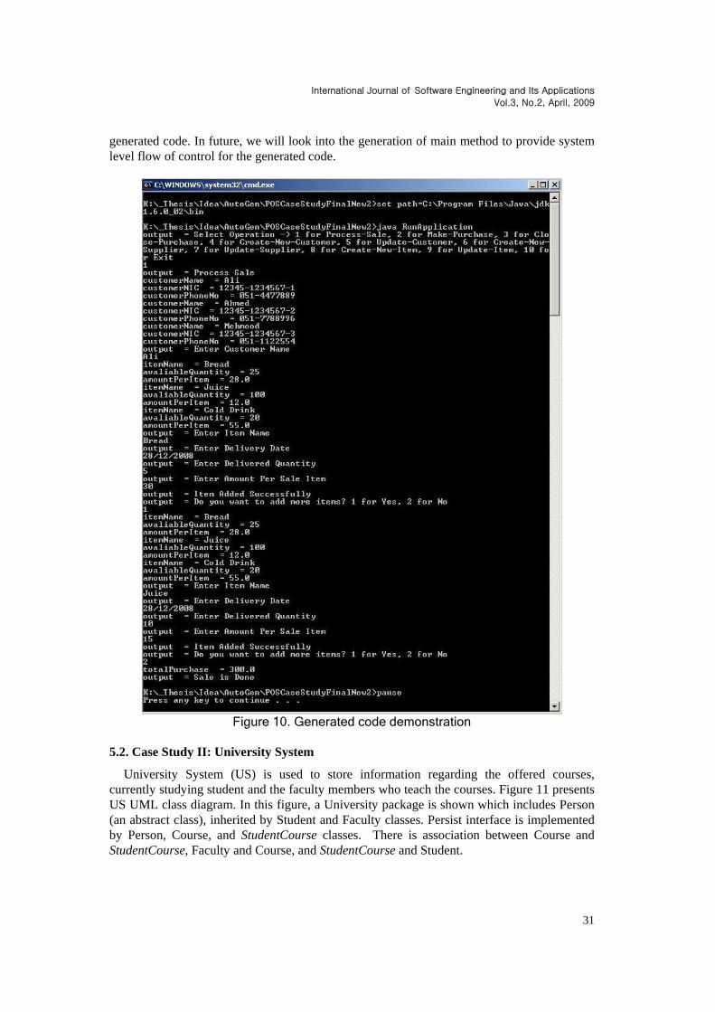
5.1.1. Generated Code Demonstration: Figure 6 shows the partial Java code generated
for POS case study from UJECTOR. The tool also provides the facility to compile and execute the generated code shown. Figure 10 presents the demonstration of the POS case study generated code. Although UJECTOR generates complete implementation of all the classes including their methods, but the main method have to be implemented to run the
International Journal of Software Engineering and Its Applications
Vol.3, No.2, April, 2009
31
generated code. In future, we will look into the generation of main method to provide system level flow of control for the generated code.
Figure 10. Generated code demonstration
5.2. Case Study II: University System
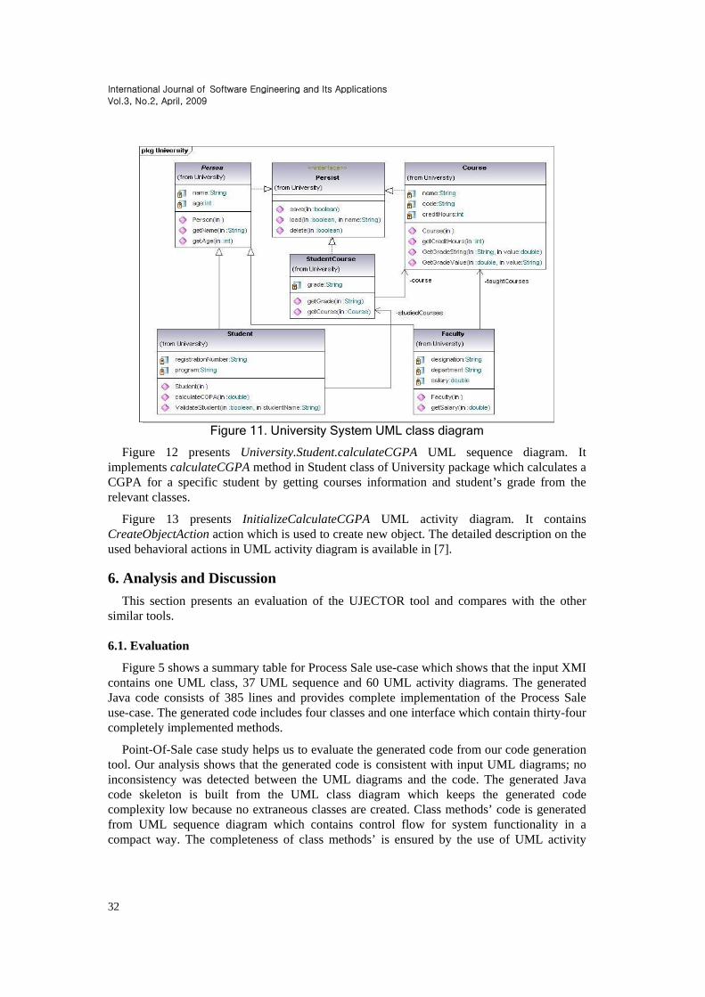
University System (US) is used to store information regarding the offered courses, currently studying student and the faculty members who teach the courses. Figure 11 presents US UML class diagram. In this figure, a University package is shown which includes Person (an abstract class), inherited by Student and Faculty classes. Persist interface is implemented by Person, Course, and StudentCourse classes. There is association between Course and StudentCourse, Faculty and Course, and StudentCourse and Student.
International Journal of Software Engineering and Its Applications
Vol.3, No.2, April, 2009
32
Figure 11. University System UML class diagram
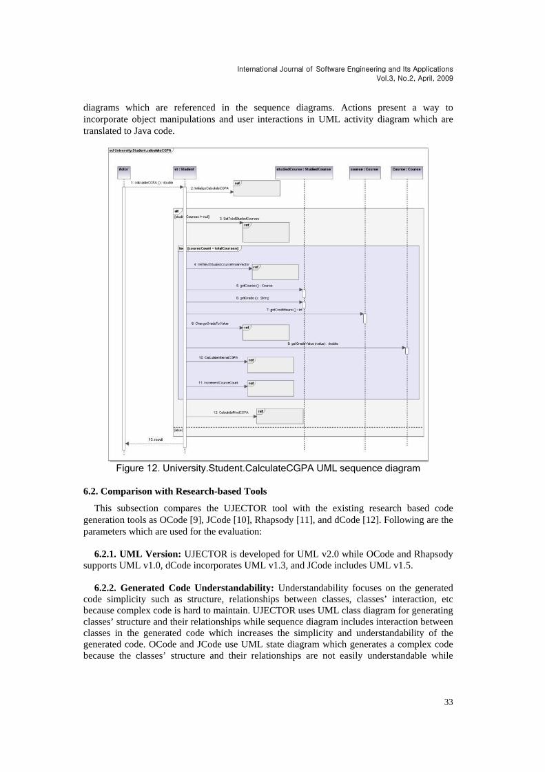
Figure 12 presents University.Student.calculateCGPA UML sequence diagram. It implements calculateCGPA method in Student class of University package which calculates a CGPA for a specific student by getting courses information and student’s grade from the relevant classes.
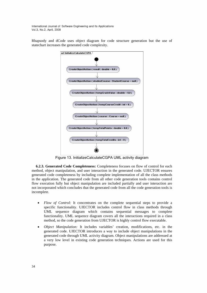
Figure 13 presents InitializeCalculateCGPA UML activity diagram. It contains CreateObjectAction action which is used to create new object. The detailed description on the used behavioral actions in UML activity diagram is available in [7]. 6. Analysis and Discussion
This section presents an evaluation of the UJECTOR tool and compares with the other similar tools. 6.1. Evaluation
Figure 5 shows a summary table for Process Sale use-case which shows that the input XMI contains one UML class, 37 UML sequence and 60 UML activity diagrams. The generated Java code consists of 385 lines and provides complete implementation of the Process Sale use-case. The generated code includes four classes and one interface which contain thirty-four completely implemented methods.
Point-Of-Sale case study helps us to evaluate the generated code from our code generation tool. Our analysis shows that the generated code is consistent with input UML diagrams; no inconsistency was detected between the UML diagrams and the code. The generated Java code skeleton is built from the UML class diagram which keeps the generated code complexity low because no extraneous classes are created. Class methods’ code is generated from UML sequence diagram which contains control flow for system functionality in a compact way. The completeness of class methods’ is ensured by the use of UML activity
International Journal of Software Engineering and Its Applications
Vol.3, No.2, April, 2009
33
diagrams which are referenced in the sequence diagrams. Actions present a way to incorporate object manipulations and user interactions in UML activity diagram which are translated to Java code.
Figure 12. University.Student.CalculateCGPA UML sequence diagram
6.2. Comparison with Research-based Tools
This subsection compares the UJECTOR tool with the existing research based code generation tools as OCode [9], JCode [10], Rhapsody [11], and dCode [12]. Following are the parameters which are used for the evaluation:
6.2.1. UML Version: UJECTOR is developed for UML v2.0 while OCode and Rhapsody
supports UML v1.0, dCode incorporates UML v1.3, and JCode includes UML v1.5. 6.2.2. Generated Code Understandability: Understandability focuses on the generated
code simplicity such as structure, relationships between classes, classes’ interaction, etc because complex code is hard to maintain. UJECTOR uses UML class diagram for generating classes’ structure and their relationships while sequence diagram includes interaction between classes in the generated code which increases the simplicity and understandability of the generated code. OCode and JCode use UML state diagram which generates a complex code because the classes’ structure and their relationships are not easily understandable while
International Journal of Software Engineering and Its Applications
Vol.3, No.2, April, 2009
34
Rhapsody and dCode uses object diagram for code structure generation but the use of statechart increases the generated code complexity.
Figure 13. InitializeCalculateCGPA UML activity diagram
6.2.3. Generated Code Completeness: Completeness focuses on flow of control for each
method, object manipulation, and user interaction in the generated code. UJECTOR ensures generated code completeness by including complete implementation of all the class methods in the application. The generated code from all other code generation tools contains control flow execution fully but object manipulation are included partially and user interaction are not incorporated which concludes that the generated code from all the code generation tools is incomplete.
Flow of Control: It concentrates on the complete sequential steps to provide a specific functionality. UJECTOR includes control flow in class methods through UML sequence diagram which contains sequential messages to complete functionality. UML sequence diagram covers all the interactions required in a class method, so the code generation from UJECTOR is highly control flow executable.
Object Manipulation: It includes variables’ creation, modifications, etc. in the generated code. UJECTOR introduces a way to include object manipulations in the generated code through UML activity diagram. Object manipulations are addressed at a very low level in existing code generation techniques. Actions are used for this purpose.
International Journal of Software Engineering and Its Applications
Vol.3, No.2, April, 2009
35
User Interaction: It deals with getting input and showing output to the end user. UJECTOR provides a mechanism to include user interactions in the generated code which is not addressed ever in the generated code from the existing code generation techniques. Actions are used for this purpose.
Our analysis of UJECTOR with OCode, JCode, Rhapsody, and dCode concludes that the generated code from UJECTOR is more understandable than the generated code from all other tools. We strive to generate fully functional code which is the most distinguishable feature of our code generation tool. 6.3. Comparison with UML Case Tools
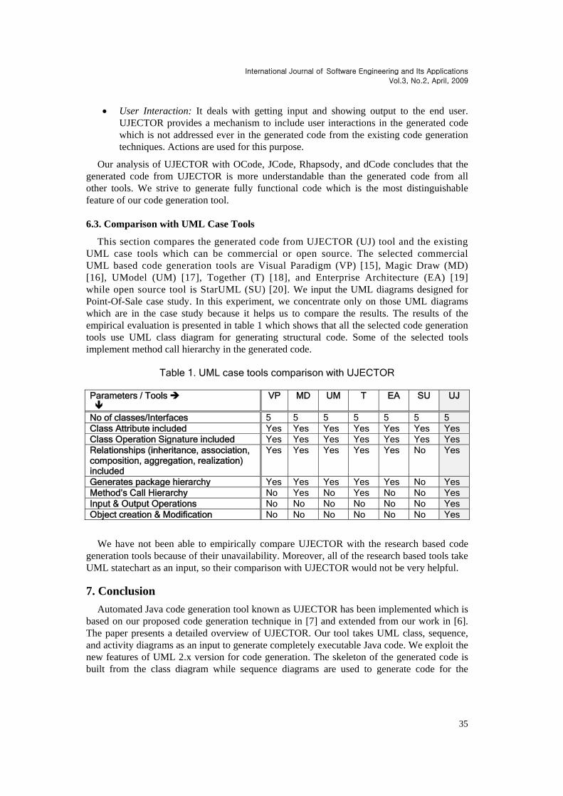
This section compares the generated code from UJECTOR (UJ) tool and the existing UML case tools which can be commercial or open source. The selected commercial UML based code generation tools are Visual Paradigm (VP) [15], Magic Draw (MD) [16], UModel (UM) [17], Together (T) [18], and Enterprise Architecture (EA) [19] while open source tool is StarUML (SU) [20]. We input the UML diagrams designed for Point-Of-Sale case study. In this experiment, we concentrate only on those UML diagrams which are in the case study because it helps us to compare the results. The results of the empirical evaluation is presented in table 1 which shows that all the selected code generation tools use UML class diagram for generating structural code. Some of the selected tools implement method call hierarchy in the generated code.
Table 1. UML case tools comparison with UJECTOR
Parameters / Tools
VP MD UM T EA SU UJ
No of classes/Interfaces 5 5 5 5 5 5 5 Class Attribute included Yes Yes Yes Yes Yes Yes Yes Class Operation Signature included Yes Yes Yes Yes Yes Yes Yes Relationships (inheritance, association, composition, aggregation, realization) included
Yes Yes Yes Yes Yes No Yes
Generates package hierarchy Yes Yes Yes Yes Yes No Yes Method’s Call Hierarchy No Yes No Yes No No Yes Input & Output Operations No No No No No No Yes Object creation & Modification No No No No No No Yes
We have not been able to empirically compare UJECTOR with the research based code generation tools because of their unavailability. Moreover, all of the research based tools take UML statechart as an input, so their comparison with UJECTOR would not be very helpful. 7. Conclusion
Automated Java code generation tool known as UJECTOR has been implemented which is based on our proposed code generation technique in [7] and extended from our work in [6]. The paper presents a detailed overview of UJECTOR. Our tool takes UML class, sequence, and activity diagrams as an input to generate completely executable Java code. We exploit the new features of UML 2.x version for code generation. The skeleton of the generated code is built from the class diagram while sequence diagrams are used to generate code for the

International Journal of Software Engineering and Its Applications
Vol.3, No.2, April, 2009
36
methods. UML activity diagrams are referenced in sequence diagrams, which provide behavioral actions to incorporate object manipulations and user interactions. UML activity diagram is included to ensure class methods’ complete implementation. Two case studies have been used to validate our implemented tool. We empirically evaluate the generated code from UJECTOR with different existing UML case tools. The results show that the generated Java code is consistent with UML diagrams. The generated code is fully functional and understandable. References [1] Object Management Group (OMG), Unified Modeling Language Specification, Version 2.1.1, (2007-02-07).
[2] Booch, G., Object Oriented Design with Applications, Benjamin/Cummings, Redwood, California, 1991. ISBN: 0-8053-0091-0, ISSN: 0896-8438
[3] Coad, P., and E. Youdon, Object-Oriented Analysis, Prentice Hall, Eaglewood Cliffs, New Jersey, 1991. ISBN: 0-13-630070-7
[4] Jacobson, I., G. Booch, and J. Rumbaugh, The Unified Software Development Process, Addison-Wesley, Reading, MA, 1999.
[5] Object Management Group (OMG), MDA Guide (2003), Version 1.0.1, http://www.omg.org/docs/omg/03-06-01.pdf.
[6] M. Usman, A. Nadeem, and T. Kim, “UJECTOR: A tool for Executable Code Generation from UML Models”, International Conference on Advanced Software Engineering and its Applications (ASEA’08), IEEE Computer Society Press, Hainan Island, China, December. 13-15, 2008, pp. 165-170.
[7] M. Usman, “Automated Generation of Executable Java Code from UML Diagrams”, Masters Thesis, Mohammad Ali Jinnah University, Islamabad, Pakistan, December 2008.
[8] Object Management Group (OMG), UML Superstructure: http://www.omg.org/docs/ ptc/06-04-02.pdf.
[9] J. Ali, and J. Tanaka, “An Object Oriented Approach to Generate Executable Code from the OMT-based Dynamic Model”, Journal of Integrated Design and Process Science (SDPT), vol. 2, no. 4, 1998, pp.65-77.
[10] I. A. Niaz, and J. Tanaka, “An Object-Oriented Approach to Generate Java Code from UML Statecharts”, International Journal of Computer & Information Science (IJCIS), vol. 6, no. 2, 2005, pp. 83-98.
[11] D. Harel, and E. Gery, “Executable Object Modeling with Statecharts”, 18th International Conference on Software Engineering (SE’96), IEEE Computer Society Press, Berlin, Germany, March 25-29, 1996, pp. 246-257.
[12] J. Ali, and J. Tanaka, “Implementing the Dynamic Behavior Represented as Multiple State Diagrams and Activity Diagrams”, Journal of Computer Science & Information Management (JCSIM), vol. 2, no. 1, 2001, pp.24-34.
[13] Object Management Group (OMG), XML Metadata Interchange (XMI) Version 2.1.1, http://www.omg.org/docs/formal/07-12-01.pdf
[14] Larman, C., Applying UML and Patterns: An Introduction to Object-Oriented Analysis and Design (3rd Edition), Prentice Hall PTR Upper Saddle River, NJ, USA, 2004. ISBN: 0131489062
[15] Visual Paradigm Homepage, 2008. http://www.visual-paradigm.com
[16] Magic Draw Homepage, 2008. http://www.magicdraw.com
[17] Altova, UModel Homepage, 2008. http://www.altova.com/products/umodel/uml_tool.html
[18] Borland, Together, 2008. http://www.borland.com/us/products/together/index.html
[19] Sprax Systems, Enterprise Architect Homepage, 2008. http://www.sparxsystems.com/products/ea/index.html
[20] StarUML, 2008. http://staruml.sourceforge.net/en/download.php

International Journal of Software Engineering and Its Applications
Vol.3, No.2, April, 2009
37
Authors
Muhammad Usman is currently working as a Research Assistant in Center for Software Dependability at Mohammad Ali Jinnah University, Islamabad, Pakistan. He completed his Bachelors and Masters degree in Computer Science from Mohammad Ali Jinnah University, Islamabad, Pakistan. This publication is based on his work in Master Thesis. His research interests are model driven architecture, model transformations, UML modeling, UML based code generation.
Aamer Nadeem is currently an Associate Professor in the Department of Computer Science at Mohammad Ali Jinnah University, Islamabad, Pakistan. He is also Director of the Center for Software Dependability at Mohammad Ali Jinnah University. He received his MSc in computer science from Quaid-i-Azam University, Islamabad, MS in software engineering from National University of Sciences and Technology, and PhD in software engineering from Mohammad Ali Jinnah University. He is a professional member of the ACM.

International Journal of Software Engineering and Its Applications
Vol.3, No.2, April, 2009
38