3 channel digital storage oscilloscope (dso) instrument · 2019-02-25 · abi electronics test...
TRANSCRIPT


ABI Electronics · Test & Measurement Systems · 2
HORIZONTAL (TIMEBASE) SPECIFICATIONS
Timebase ranges
3 Channel Digital Storage Oscilloscope (DSO) Instrument
VERTICAL SPECIFICATIONS
Analogue Bandwidth (-3dB) 350 MHz
20 MHz, 100 MHz, 200 MHz, switchableBandwidth Limiting
Rise time (10% to 90%, calculated) 1ns
±40 mV to ±8 V, in 8 rangesInput ranges (full scale)
50 ns/div to 1000 s/div (real-time sampling)1 ns/div to 20 ns/div (ERS)
ACQUISITIONResolution
500 MS/s / ChannelMaximum real-time sampling rate
25 GS/sMaximum ERS rate
1,048,576 Samples / ChannelBuffer size
8 bits
Input sensitivity 10 mV/div to 2 V/div
1 MΩ (AC or DC or GND)Input coupling
Input characteristics 1 MΩ || 15 pF
Analog offset range ±40 mV input range: ±40 mV±80 mV input range: ±80 mV±200 mV input range: ±200 mV±400 mV input range: ±400 mV±800 mV input range: ±800 mV±2 V input range: ±2 V ±4 V input range: ±4 V±8 V input range: ±8 V
TRIGGERING
Sources DSO Channels 1 to 3AWG Channel 1 to 2FC Channel 1
Auto, normal, singleModes
Advanced types (real-time mode) Edge (AC, DC, HF reject, LF reject)
Trigger level range ±40 mV input range: ±40 mV±80 mV input range: ±80 mV±200 mV input range: ±200 mV±400 mV input range: ±400 mV±800 mV input range: ±800 mV±2 V input range: ±2 V±4 V input range: ±4 V±8 V input range: ±8 V
Trigger sensitivity 1 division up to full bandwidth of scope
AUTOMATIC MEASUREMENTS
Types
Amplitude,Peak-Peak,Top,Top Peak, Base, Base Peak,Mean, RMS, Cyclic Mean, Cyclic RMS, Overshoot, Un-dershoot, Crest Factor, V Resolution, Period, Frequency, Rise Time, Fall Time, Pos Time Constant, Neg Time Constant, Positive Width, Negative Width, Positive Slew, Negative Slew, Bandwidth, Duty Cycle, T Resolution, Cycle Count
PROTECTIONInput Over Voltage ±200V MAX
Minimum, maximum, average and sweeps
Statistics
Selectable inside or outside mode with voltage and time tolerances
Mask Comparison
STANDARD WAVEFORM FEATURESWaveform Shapes
Maximum combined output voltage: ±10 V
ARBITRARY WAVEFORM FEATURES
Channels have fully independent control and are asynchronous with respect to each other and to other instruments on the MIS 4. Independent variable clock control for true repetitive outputs at any frequency, with zero cycle to cycle jitter.
ADDITIONAL INFO
Amplitude / Offset Adjustment
2 Channel Arbitrary Waveform Generator (AWG) Instrument
0.5 Hz to 25 MHzSignal Frequency
Sample Rate Range 2 kS/s to 200 MS/s (continuously variable clock)
4,096 Samples / ChannelBuffer Size
PROTECTION
Input Over Voltage ±15 V
Continuous with automatic recoveryOutput Short Circuit
OUTPUT SPECIFICATIONS
Voltage Output Range -10 V to +10 V
10 mVAmplitude/Offset Set Resolution
Current Limit (Drive Strength) ±200 mA / Channel
50 Ω (±1%)Output Impedance
0% to 100%Duty Cycle Range
DC, Sine, Square, Triangle, Ramp+, Ramp-
TRIGGERINGSources
Normal or SingleModes
-10 V to +10 VTrigger Output Level
Cycle or EdgeTrigger Output Mode
DSO Channels 1 to 3, AWG Channel 1 to 2 or FC Channel 1
14 BitsResolution
INPUT SPECIFICATIONS
Voltage Range ±3.3 V
50 Ω (±1%)Impedance
4 Channel Frequency Counter (FC and DSOFC) Instrument
DC to 1.1 GHzFrequency Range
AUTOMATIC MEASUREMENTS
Statistics Minimum, maximum, average and sweeps
Selectable inside or outside mode with target and tolerances
Comparison
±40 mV to ±8 V (see DSO)
Sensivity -21dBm @ 100kHz-1.2dBm @ 1.1GHz
1 MΩ || 15 pF
DC to 350 MHz
1 division (see DSO)
Dedicated Channel DSO Channel
GATE TRIGGERING
Sources DSO Channels 1 to 3, AWG Channel 1 to 2 or FC Channel 1

3ABI Electronics · Test & Measurement Systems ·
8 Channel Universal Input Output (UIO) Instrument
OUTPUT SPECIFICATIONS
Voltage Resolution
Voltage Output Range -10 V to +10 V
10 mV
Output Short Circuit Continuous with automatic recovery
PROTECTION
METER SPECIFICATIONS
Channels are non-isolated, constant voltage and can be accessed via the multiway connector. Each channel has an independent mode control. Pre-sets are provided for CMOS, LVCMOS, ECL, TTL and LVTTL logic levels.
1 mV
1 mA
ADDITIONAL INFO
Voltage Set Resolution
Current Resolution
Current Limit (Drive Strength) ±20 mA / Channel
Input Over Voltage ±15 V (transient suppressor)
Voltage Input Range -12 V to +12 V
INPUT SPECIFICATIONS
Voltage Resolution 1 mV
DIRECT VOLTAGE
Voltage Resolution
Ranges ±1 V, ±10 V, ±100 V and ±500 V
100 µV to 10 mV
ALTERNATING VOLTAGE @ 50-60Hz (TRUE RMS, AC or AC+DC)
METER SPECIFICATIONS
The DVM shares its common terminal with the DOM but is isolated (500V MAX) from all other instruments.
4½ Digits 20,000 Count
ADDITIONAL INFO
Resolution
2 Channel Digital Voltmeter (DVM) Instrument
10 MΩInput Impedance
Ranges 1 V, 10 V, 100 V and 500 V
toBandwidth
100 µV to 10 mVResolution
10 MΩInput Impedance
AUTOMATIC MEASUREMENTS
Statistics Minimum, maximum, average and sweeps
Selectable inside or outside mode with target and tolerances
Comparison
DIRECT CURRENT
Resolution
Ranges ±100 mA, ±1 A and ±10 A
10 µV to 1 mA
ALTERNATING CURRENT @ 50-60Hz (TRUE RMS, AC or AC+DC)
METER SPECIFICATIONS
The DAM is isolated (500V MAX) from all other instruments.
4½ Digits 20,000 Count
ADDITIONAL INFO
Resolution
1 Channel Digital Ammeter (DAM) Instrument
10 mΩ + cable resistanceSense Resistance
Ranges 100 mA, 1 A and 10 A
toBandwidth
10 µV to 1 mAResolution
10 mΩ + cable resistanceSense Resistance
AUTOMATIC MEASUREMENTS
Statistics Minimum, maximum, average and sweepsSelectable inside or outside mode with target and tolerances
Comparison
Fuse Fast Acting 12.5 A
RESISTANCE
Resolution
Ranges 10 Ω, 100 Ω, 1 kΩ, 10 kΩ, 100 kΩ, 1 MΩ and 10 MΩ
1 mΩ to 1 kΩ
CONTINUITY
METER SPECIFICATIONS
The DOM shares its common terminal with the DVM but is isolated (500V MAX) from all other instruments
4½ Digits 20,000 Count
ADDITIONAL INFO
Resolution
1 Channel Digital Ohmmeter (DOM) Instrument
Ranges 0 Ω to 1 kΩ
100 mΩResolution
AUTOMATIC MEASUREMENTS
Statistics Minimum, maximum, average and sweeps
Selectable inside or outside mode with target and tolerances
Comparison
DIODE
Ranges 0 V to 2 V
100 µVResolution
1 mATest Current
ABI Electronics · Test & Measurement Systems · 4
OUTPUT SPECIFICATIONS
Voltage Resolution
Voltage Output +5 V (±2%)
1 A
Output Short Circuit Continuous with automatic recovery
PROTECTION
METER SPECIFICATIONS
Outputs are fixed, non-isolated, constant voltage and can be accessed via the multiway connector. Each output has an independent On/Off control, however, additional control buttons are provided which turn all outputs on or off simultaneously.
10 mV
1 mA
ADDITIONAL INFO
Current Limit
Current Resolution
1 A 100 mA 100 mA
+3.3 V (±2%) +12 V (±2%) -12 V (±2%)
4 Channel Auxiliary Power Supply (APS) Instrument
Errors and omissions excepted. Windows is a registered trade mark of MicrosoftCorporation in the United States and other countries.Copyright 2015 ABI Electronics Limited - Registered in England - No 1824588
Ordering Information
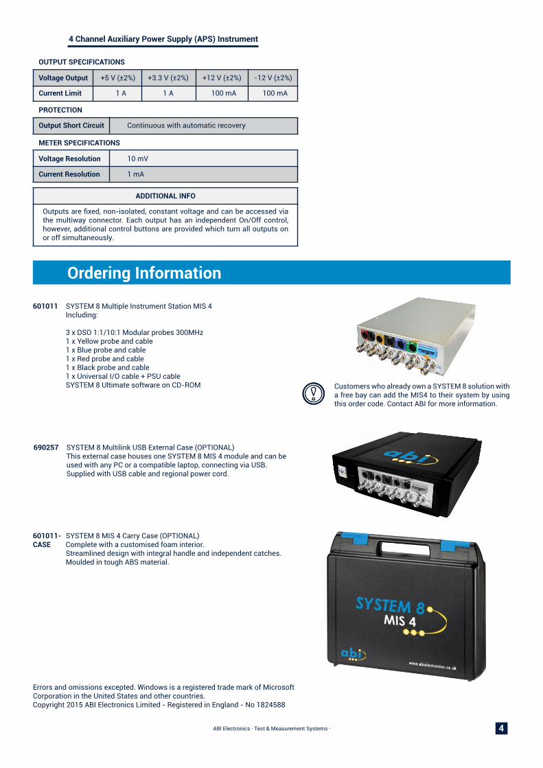
601011 SYSTEM 8 Multiple Instrument Station MIS 4 Including: 3 x DSO 1:1/10:1 Modular probes 300MHz 1 x Yellow probe and cable 1 x Blue probe and cable 1 x Red probe and cable 1 x Black probe and cable 1 x Universal I/O cable + PSU cable SYSTEM 8 Ultimate software on CD-ROM
690257 SYSTEM 8 Multilink USB External Case (OPTIONAL) This external case houses one SYSTEM 8 MIS 4 module and can be used with any PC or a compatible laptop, connecting via USB. Supplied with USB cable and regional power cord.
601011- SYSTEM 8 MIS 4 Carry Case (OPTIONAL) CASE Complete with a customised foam interior. Streamlined design with integral handle and independent catches. Moulded in tough ABS material.
Customers who already own a SYSTEM 8 solution with a free bay can add the MIS4 to their system by using this order code. Contact ABI for more information.

5ABI Electronics · Test & Measurement Systems ·
Installation Options & Requirements
*Back view - Internal case
* Back view - External case
POWER REQUIREMENTSExternal caseVoltage input range 100-240 VAC auto sensingPower consumption 140 WInternal case (installation on PC 5.25” bay or existing SYSTEM 8 solution)Voltage input range +5V, 2A (minimum at rated full load) +12V, 2A (minimum at rated full load)
PHYSICAL CHARACTERISTICSDimensions External case 250mmX287mmX74mm Internal case 204.8mmX148mmX42.3mm Weight External case 3.35Kg (7 lb 6.2 oz) Internal case 0.80Kg (1.76 lb)
Connectivity 3 channel oscilloscope / frequency counter BNC 2 channel arbitrary waveform generator BNC 1 channel universal frequency counter BNC Auxiliary power supply and Digital I/O Type Multiway connector (14 pins) Cable (included) 12 hooks + 2 grounds 2 channel Voltmeter 4 mm banana jack 1 channel Ohmmeter 4 mm banana jack 1 channel Ammeter 4 mm banana jack USB B type Power input connector IEC C13 (External case) Molex 4 pins (Internal case)
ENVIRONMENTALOperating temperature 0 to 40 ºC
External Case - 690257
Internal Case - 601011
PC REQUIREMENTSIntel core i3 or similar @ 1.6 GHz or above. 80GB HDD, 3GB RAM. USB 2.0 and above.Windows XP, Windows Vista, Windows 7 & Windows 8.1 (32 & 64 bits) versions. 1366x768 minimum display resolution.
