3 continuous heat processing - ufuftp.feq.ufu.br/luis_claudio/books/e-books/food/therma… · ·...
TRANSCRIPT

3.1 Introduction
An improvement in quality was one of the main driving forces behind thedevelopment of continuous heat processes. Liquid and semi-liquid products suchas milks, juices and sauces suffered from overprocessing in the traditional lowtemperature–long time of in-container or batch processing. Caramelisedflavours, poor colour retention and a lack of a reproducible product were allproblems associated with products processed by batch methods. Improvingquality whilst maintaining product safety was the main aim for those developingcontinuous processing approaches.
The achievement of safe products by thermal processing is based upon thetheory behind the destruction of microorganisms. Products must be heated to aset temperature for a set time in order to achieve a commercially sterile product.For continuous heat processing, also called continuous flow processing, theproduct is thermally processed before being placed into an appropriatecontainer, on a continuous basis through a heat exchange plant. Heat exchangeapparatus will be used for both the heating and cooling (if required) phase of theprocess.
In a continuous system the foods under consideration are liquid or semi-liquidproducts, which may be pumped through a system, heated and cooled whilstcontinuously flowing down the processing line. A wide range of products areprocessed by this method, either as the main process to achieve a safe product(as in Ultra Heat Treated or Ultra High Temperature (UHT) processing) or as astep within a further process.
Continuous heat processing is not a new technology and several good textsexist which give background to the developments through the years in this area.
3
Continuous heat processingS.P. Emond, Campden & Chorleywood Food Research Association,Chipping Campden

This chapter will review the current status within processing equipment andhighlight the developments which have been made in order to take into accountthe processor’s requirements for safe, reproducible systems which will ensure asafe product, maintain product quality and also maximise process efficiency.
The three main types of process that are suitable for continuous flowprocessing are, aseptic systems (high and low acid), hot fill systems andpasteurisation processes. Aseptically packed products are processed attemperatures that will render the product commercially sterile. High acidproducts such as juices can be processed at pasteurisation temperatures todestroy the microorganisms that can cause the spoilage of the product; these arethen rapidly cooled (to reduce losses of volatiles within the product) and filledinto a pre-sterilised pack under sterile conditions. Low acid products willundergo the same principle, however the temperatures employed are muchhigher to ensure no survival of pathogenic bacteria. The temperatures usedwithin a UHT system for low acid products are usually in the range 125ºC to145ºC, so allowing for much shorter holding times and promoting a higherquality product. Continuous flow processing systems can also be used in hot fillprocesses for high acid products that would otherwise lose product qualitythrough slow cooling methods. High acid sauces, purees and chutneys canbenefit from a continuous process by heating the product to pasteurisationtemperatures and then filling directly into suitable containers, using the heat ofthe product to decontaminate the packaging. This method allows for a muchquicker throughput than a typical batch process would offer. The final heatingmethod for this type of system is pasteurisation of low acid products that willthen be cooled and held under chilled conditions (e.g. pasteurised milk, juicesand soups). This processing step extends the shelf-life and ensures a safeproduct. The product must be chilled to maintain its safety and qualitythroughout the shelf-life. Shelf-lives of up to ten days can be achieved for someproducts.
There are two main options open to a food manufacturer considering acontinuous heat process, to process by indirect method, or by direct method.Indirect heating involves a heat transfer surface between the product and theheating media. Direct heating occurs where the product and heating media are indirect contact. Figure 3.1 illustrates the main options open to a processor.Another established continuous heating method available is Ohmic heating. Thiswill be discussed in Chapter 12.
3.2 Indirect heating
Indirect heating methods rely on having a heat transfer surface between theproduct and the heating media. There are three main types of indirect heatingsystem: plate heat exchangers, tubular heat exchangers and scraped surface heatexchangers. Each system has benefits and drawbacks depending on the productrequiring processing and each has been adapted since the advent of these
30 Thermal technologies in food processing

systems to process a wider range of products and enabling the systems tocompete directly.
3.2.1 Plate heat exchangersPlate heat exchangers are a well-established method for processing homogenousproducts of low viscosity, making them ideal for use within dairies. Plate heatexchangers consist of a series of plates connected on a frame. The product andheating (or cooling media) flow in alternate channels in thin layers to providegood heat transfer conditions (Fig. 3.2). The plates are sealed by elastic sealinggaskets cemented into a perforated groove. Generally the plates are of polishedstainless steel of 0.5–1.25 mm in thickness separated by 3–6 mm. The surface ofthe plates is usually corrugated in order to increase the area available for heattransfer and enhance the turbulence present in the system, resulting in a highthermal efficiency. Thermal regeneration can lower energy costs substantially.The narrow gaps mean that the units are best suited to low viscosity homogenousproducts. Attempts to process particulate products (e.g. fruit juice cells) mayresult in blocked channels and eventually blown plates due to the pressureimbalance between product and media sides of the plates. For this reason onlyproducts with less than 10% cell content are normally recommended whenprocessing with plate heat exchangers.
The design of the plates can vary from supplier to supplier, each havingdifferent designs to maximise process efficiency and ensure product safety.Plates can be product specific. The corrugations that are present in plates areusually of a chevron or herringbone design in order to develop a turbulent flowthrough the plate as it passes through the plate pack (so increasing heat transfer).As the plates are assembled, the herringbone pattern is usually alternated, withthe chevrons going up on one plate and down on the next, creating the channelsthrough which the product can flow. The thickness of the plates will vary from
Fig. 3.1 Methods of continuous heat processing.
Continuous heat processing 31

type to type, depending on the working pressure expected from the plates, butthese can also be of thin gauge material which will ensure a high heat transfer.The design of the pattern on the plates in most cases allows for support of thewhole plate pack, the plates are touching a designated point to ensure that thestrength within the system is maintained but also the ease of cleanability is takeninto account. The plates may also have larger spaces between, which will allowsmall particles to be processed in the system.
A further development in this area has been with the double-separation plate,which is designed for highest security, stopping contamination between theheating media and the processed product. The design is similar to a traditionalplate heat exchanger but plate pairs are mounted together and are welded at the
Fig. 3.2 Flow through a plate heat exchanger (courtesy of Tetra Pak).
32 Thermal technologies in food processing
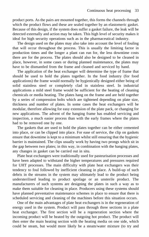
product ports. As the pairs are mounted together, this forms the channels throughwhich the product flows and these are sealed together by an elastomeric gasket.Because of this design, if the system does suffer a gasket failure, the leak will bedetected externally and action may be taken. This high level of security makes itideal for high security operations such as in the pharmaceutical industry.
The design used on the plates may also take into account the level of foulingthat will occur throughout the process. This is usually the limiting factor inproduction times and the longer a plant can run for, the less downtime coststhere are for the process. The plates should also be designed to be cleaned inplace, however, in some cases or during planned maintenance, the plates mayhave to be dismantled from the frame and cleaned and serviced by hand.
The application of the heat exchanger will determine the type of frame thatshould be used to hold the plates together. In the food industry (for foodapplications) the frame would normally be hygienically designed either being ofsolid stainless steel or completely clad in stainless steel. In industrialapplications a mild steel frame would be sufficient for the heating of cleaningchemicals or media heating. The plates hang on the frame and are held togetherby a series of compression bolts which are tightened depending on plate size,thickness and number of plates. In some cases the heat exchangers will bemodular, therefore allowing for easy extension of the plate pack, or changing fornew applications. The advent of the hanging frame has enabled servicing andinspection, a much easier process than with the early frames where the plateshad to be removed one by one.
The gaskets that are used to hold the plates together can be either cementedinto place, or can be clipped into place. For ease of service, the clip on gasketsensure that downtime is kept to a minimum whilst still ensuring that the hygienicbarrier is maintained. The clips usually work by having two prongs which sit inthe gap between two plates; in this way, in combination with the hanging plates,any changes in gasket can be carried out in situ.
Plate heat exchangers were traditionally used for pasteurisation processes andhave been adapted to withstand the higher temperatures and pressures requiredfor UHT processes. The main difficulty with plate heat exchangers was theirtendency to foul followed by inefficient cleaning in place. A build-up of suchdebris in the streams in the system may ultimately lead to the product beingundersterilised leading to product spoilage or an unsterile product. Themanufacturers of such systems are designing the plates in such a way as tomake them suitable for cleaning in place. Producers using these systems shouldhave planned preventative maintenance schemes in place to ensure that there isscheduled servicing and cleaning of the machines before this situation occurs.
One of the main advantages of plate heat exchangers is in the regeneration ofenergy used in the system. Product will pass through three sections in a plateheat exchanger. The first section will be a regeneration section where theincoming product will be heated by the outgoing hot product. The product willthen enter the main heating section with the heating media on one side, whichcould be steam, but would more likely be a steam/water mixture (to try and
Continuous heat processing 33
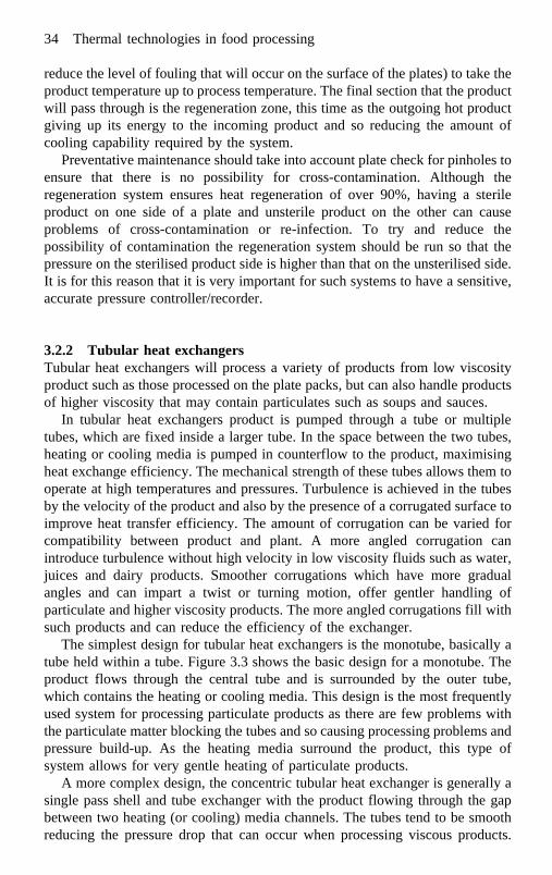
reduce the level of fouling that will occur on the surface of the plates) to take theproduct temperature up to process temperature. The final section that the productwill pass through is the regeneration zone, this time as the outgoing hot productgiving up its energy to the incoming product and so reducing the amount ofcooling capability required by the system.
Preventative maintenance should take into account plate check for pinholes toensure that there is no possibility for cross-contamination. Although theregeneration system ensures heat regeneration of over 90%, having a sterileproduct on one side of a plate and unsterile product on the other can causeproblems of cross-contamination or re-infection. To try and reduce thepossibility of contamination the regeneration system should be run so that thepressure on the sterilised product side is higher than that on the unsterilised side.It is for this reason that it is very important for such systems to have a sensitive,accurate pressure controller/recorder.
3.2.2 Tubular heat exchangersTubular heat exchangers will process a variety of products from low viscosityproduct such as those processed on the plate packs, but can also handle productsof higher viscosity that may contain particulates such as soups and sauces.
In tubular heat exchangers product is pumped through a tube or multipletubes, which are fixed inside a larger tube. In the space between the two tubes,heating or cooling media is pumped in counterflow to the product, maximisingheat exchange efficiency. The mechanical strength of these tubes allows them tooperate at high temperatures and pressures. Turbulence is achieved in the tubesby the velocity of the product and also by the presence of a corrugated surface toimprove heat transfer efficiency. The amount of corrugation can be varied forcompatibility between product and plant. A more angled corrugation canintroduce turbulence without high velocity in low viscosity fluids such as water,juices and dairy products. Smoother corrugations which have more gradualangles and can impart a twist or turning motion, offer gentler handling ofparticulate and higher viscosity products. The more angled corrugations fill withsuch products and can reduce the efficiency of the exchanger.
The simplest design for tubular heat exchangers is the monotube, basically atube held within a tube. Figure 3.3 shows the basic design for a monotube. Theproduct flows through the central tube and is surrounded by the outer tube,which contains the heating or cooling media. This design is the most frequentlyused system for processing particulate products as there are few problems withthe particulate matter blocking the tubes and so causing processing problems andpressure build-up. As the heating media surround the product, this type ofsystem allows for very gentle heating of particulate products.
A more complex design, the concentric tubular heat exchanger is generally asingle pass shell and tube exchanger with the product flowing through the gapbetween two heating (or cooling) media channels. The tubes tend to be smoothreducing the pressure drop that can occur when processing viscous products.
34 Thermal technologies in food processing

Concentric tubes have a single channel design where product flows through atube which is surrounded by a second jacketed tube containing the heating (orcooling) media. Through the centre of the product tube is a further tube whichalso has the heating or cooling media flowing through it. In this way the productis surrounded by the media thus giving two heat transfer surfaces allowing for amore efficient heat transfer. As there is generally only one tube for the productto flow down this makes the plant easier to clean and to sterilise. Having aminimal effect on the flow patterns of the product, a uniform product quality forviscous products such as fruit purees, concentrates and sauces, such as mustardand mayonnaise can be achieved. The gap for the product flow can be designeddepending on the application, giving wider gaps for products containingparticulates.
A third design for tubular heat exchangers is the multitube system (Fig. 3.4).This can be anything from two to several parallel tubes, through which theproduct flows, surrounded by a casing which contains the heating mediaallowing the heating media to be between and around each tube. The tubes canbe corrugated or smooth depending on the level of turbulence and heat transferefficiency required. The models tend to be modular in that the heat exchangerscan be put in series depending on the level of heat energy required to achieve theprocessing temperature. This design of heat exchanger can work at hightemperatures (approximately 160ºC) and pressures (approximately 6 mPa).
A variation on the multitube is the multichannel, consisting of several tubesin tubes allowing the heating media to flow either side of the product channel.This type of set-up allows for a very large heat transfer surface and thereforehigh thermal efficiency. This design also allows for heat recovery in the form of
Fig. 3.3 Typical monotube design (courtesy of Tetra Pak).
Continuous heat processing 35

product to product heating or cooling, as is achieved in plate heat exchangers.This design is based on narrow channels and is ideal for low viscosity productssuch as fruit juices.
There are several advantages for the processor using tubular heat exchangers.Designs are available to produce a wide product range. They are able to produceparticulate product up to 12 mm and maintain the particle integrity and qualitythroughout the process. One of the main advantages though, is in the very simpledesigns, which cut down on maintenance costs and downtime.
One of the disadvantages with tubular heat exchangers is the tendency toform thermal cracks, due to the changes in temperature that occur in this type ofprocess having hot product on one side of the tube and cold product or media onthe other. To overcome this a floating end design may be used; this allows theinternal tube bundle to move slightly within the outer shell, as they are notwelded together (as in other designs). The floating end configuration also allowsfor changes in the tube configuration, allowing monotubes to be replaced bymultitubes if a multipurpose system is required (e.g. in pilot scale or researchunits).
Tubular heat exchangers can also suffer very high pressure drops in thesystem (due to the long pipe lengths used in the systems) and this can lead topractical processing problems and issues with recontamination. For example, ifthe processor is processing a fruit puree at the pasteurisation temperature 95ºC,the product will flow easily down the pipe, the viscosity of the product beingmuch lower than at ambient temperatures. When the product is cooled theviscosity will rise again and cause a large pressure build-up in the system. It is
Fig. 3.4 Typical multitube design (courtesy of Tetra Pak).
36 Thermal technologies in food processing

for this reason that the pump used in the system must be well designed and ableto stand large pressure changes to ensure that blowback does not occur.
Tubular heat exchangers can also suffer from fouling and burn on. As thetubes tend to be long, the processor does not have the ability to open and inspectthe plant after processing or cleaning so any fouling problems that can occurmust be understood and strictly monitored. Finally, though regeneration ispossible (currently for low viscosity products only), the maximum that canusually be achieved is 70–75%.
3.2.3 Scraped surface heat exchangersA more complex design than the plate or tubular heat exchanger, the scrapedsurface heat exchanger offers a way of processing highly viscous productcontaining particles that traditionally have been processed by the slower, batchoperations and enables a higher quality, repeatable product to be produced. Thebasic design consists of a large tube in a tube (similar to the simple monotubes)with the heating or cooling media on the outer shell. The central processing tubecontains a shaft which is connected to a motor and is supported by bearings ateither end. The shaft has blades attached, which are designed to scrape theheating surface of the tube as the motor activates the rotation of the shaft. Thisdesign is ideal for viscous products as the rotation causes turbulence within theheating chamber, so increasing the heat transfer into the product and second, theblades scraping on the heating surface reduce the build-up of fouling that canoccur with such products. Figure 3.5 outlines the main structure of scrapedsurface heat exchangers.
The shell of the heating tube can be chrome plated nickel (due to the highthermal conductivity that it offers), stainless steel, bimetallic or chromedstainless steel, depending on the application for which it is to be used. The shellis usually of a standard diameter and manufacturers offer a range of centralshafts (or rotors) for a specific set of conditions to optimise processing. Asmaller diameter rotor will give a larger clearance within the heating chamber,therefore allowing for the processing of products with larger particles and alsoallow for a longer residence time in the heating unit. A larger diameter rotor willminimise the heating channel therefore minimising the residence time butallowing a more efficient heat transfer to occur. This design would be moreappropriate for lower viscosity products with only small particles.
Each rotor contains a set of blades and there are again several choices for theprocessor depending on application. The material of the blade should becompatible with the material of the shell of the heating tube. The scraper bladesshould not cause wearing of the outer shell (for example if stainless steel bladeswere used with a stainless steel shell) as this can cause damage to the heatexchanger, allow for foreign bodies within the product and make the plantdifficult to clean. Manufacturers offer a wide range of materials such as durableplastics (that withstand operating temperatures and conditions) which are a goodchoice as they minimise the damage that can be done to the heat exchanger.
Continuous heat processing 37

Stainless steel blades are also available for some specialist operations. Theblades are attached to the rotor in different ways; the first is a ‘floating’configuration, which enables blades to be easily attached to the rotor. As therotor rotates through the product the blades scrape at the heating surfacethroughout the chamber. For very viscous products, some manufacturers offerdifferent designs. The oval tube unit combines an oval shell containing a roundrotor. By using this format the blade angle changes as the shaft rotates withproduct forced out from under the blade as the angle closes and moves under theblade as the angle opens. This method stops any mass movement that may occurin very viscous product as the shaft rotates. The second design is a spring-loaded
Fig. 3.5 Structure of a scraped surface heat exchanger (Contherm) (courtesy of TetraPak).
38 Thermal technologies in food processing
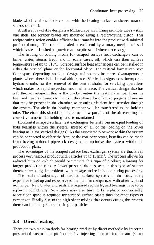
blade which enables blade contact with the heating surface at slower rotationspeeds (50 rpm).
A different available design is a Multiscrape unit. Using multiple tubes withinone shell, the scraper blades are mounted along a reciprocating piston. Thisreciprocating action enables efficient heat transfer into the product with minimalproduct damage. The rotor is sealed at each end by a rotary mechanical sealwhich is steam flushed to provide an aseptic seal (where necessary).
The heating or cooling media for scraped surface heat exchangers can bebrine, water, steam, freon and in some cases, oil, which can then achievetemperatures of up to 315ºC. Scraped surface heat exchangers can be installed ineither the vertical plane or the horizontal plane. The vertical format can savefloor space depending on plant design and so may be more advantageous inplants where there is little available space. Vertical designs now incorporatehydraulic units for the removal of the central shafts for servicing operationswhich makes for rapid inspection and maintenance. The vertical design also hasa further advantage in that as the product enters the heating chamber from thebase and travels upwards to the exit, this allows for effective purging of any airthat may be present in the chamber so ensuring efficient heat transfer throughthe system. The air in the heating chamber will be transferred to the holdingtube. Therefore this should be angled to allow purging of the air ensuring thecorrect volume in the holding tube is maintained.
Horizontal scraped surface heat exchangers benefit from an equal loading onboth bearings within the system (instead of all of the loading on the lowerbearing as in the vertical designs). As the associated pipework within the systemcan be connected to either the front or the rear connectors, benefits can be madefrom having reduced pipework designed to optimise the system within theproduction plant.
The advantages of the scraped surface heat exchanger system are that it canprocess very viscous product with particles up to 15 mm3. The process allows forreduced burn on (which would occur with this type of product) allowing forlonger production runs. A lower pressure drop is seen in this type of systemtherefore reducing the problems with leakage and re-infection during processing.
The main disadvantage of scraped surface systems is the cost, beingexpensive to set up and expensive to maintain in comparison with other types ofexchanger. New blades and seals are required regularly, and bearings have to bereplaced periodically. New tubes may also have to be replaced occasionally.More floor space is required for scraped surface plants than for other types ofexchanger. Finally due to the high shear mixing that occurs during the processthere can be damage to some fragile particles.
3.3 Direct heating
There are two main methods for heating product by direct methods: by injectingpressurised steam into product or by injecting product into steam (steam
Continuous heat processing 39

infusion). Both systems work on the principle that as the steam comes intocontact with the product it will condense and give up some latent heat so causingthe product to heat up very quickly. Both methods give practically instantaneousheating, as opposed to the indirect methods or by the very slow batch or in-container methods. Figure 3.6 compares typical heating curves for productsheated by direct, indirect and batch processes.
The basic principle for both systems is to pass the product from a balancetank to a preheating system, usually by a plate heat exchanger to 70–80ºC (for aUHT process). After this the product will pass through the main product pumpthrough to the steam injection or infusion system. After holding the product forthe required amount of time, the product passes through a reducing valve intothe cooler. The cooling mechanism for such systems must also be quick andmust remove additional water which will have been added by the heatingmethod. To achieve this the product is passed into a vacuum chamber which willbe held at a specific pressure corresponding to the product temperature beforeheating so causing the product to instantaneously boil and drive off the excessfluid whilst reducing the temperature to the preheat temperature before injection.The products processed by this method are then usually homogenised beforecooling by indirect methods to ambient or chilled temperatures by indirect heatexchange (tube or plate).
3.3.1 Steam injectionSteam injection is most suitable for low viscosity, homogenous products such asmilk and juices. There are many different types of steam injector available, withprobably the most varied designs of all the heat exchangers. There are both staticand dynamic injectors and the methods of introducing steam into the product are
Fig. 3.6 Typical heating curves for in-container, indirect and direct heatingmechanisms.
40 Thermal technologies in food processing

aimed to heat the product as quickly as possible, to minimise any possiblefouling by indirect heating methods (that is, from the surface of the injectoritself) and to maximise the length of production run that can be carried out bythe processor. The first requirement is thought to be maximised by the rapidcondensation of the steam so rapidly heating the product. The product must bemaintained at high pressure to prevent boiling at the injector; this is achieved byhaving a sufficient backpressure valve in the line before the injector system. Theheating is also maximised by ensuring that the steam has good access to theproduct if the steam is introduced as small bubbles, or as a thin sheet. Althoughfouling is less of a problem in direct systems than indirect systems, there are stillproblems seen when the injector is poorly designed. As the steam will beinjected through a nozzle or system of orifices, if this is not kept separate fromthe product the injector system will start to heat the product indirectly from thesurface of the nozzle. This will cause fouling at the surface of the injector andtherefore reduce the steam flow, so reducing the efficiency of the heating. Toovercome this, manufacturers have designed systems that have the productentering the heating zone at right angles to the injector; this keeps the productaway from the injector head and reduces fouling. After heating, the productpasses through a reducing valve before entering the flash vacuum cooler whichis held at a pressure suitable to cause the product to boil and drive off the addedwater from the steam injection. Control of the pressure in this system is neededfor two reasons. First, this is to ensure that the correct amount of water is drivenoff, and second, that any undesirable volatile odours that may have developedduring the injection process are removed. The flash vacuum chamber does bringits own problems however, as operating this at pressures lower than atmosphericpressure may allow contaminants to be sucked into the chamber. In order toreduce this, aseptic systems apply steam barriers to connecting joints movingseals and valves so that any material that may be sucked in will be sterilisedbefore re-infecting both plant and product.
Steam injection can be quite damaging to products due to the aggressivemethod of heating taking place. The rapid condensation of the steam causeschanges in pressure in the liquid. In milk products this is thought to break downhomogenisation of the product and can cause the formation of casein aggregatesgiving a chalky mouthfeel. In order to reduce this, it is necessary after directsteam injection to homogenise (aseptically) such products.
3.3.2 Steam infusionSteam infusers were designed to give a gentler process than that achieved bysteam injection. Suitable for the same types of product, infusion systems canalso be modified to handle small particles (such as cells in juices). The basis forthis method is to introduce preheated product into a chamber containing steam atthe temperature required for sterilisation. The steam chamber is usually apressure vessel with a conical-shaped base through which the heated productfalls into the holding section. Different types of infusion systems are available
Continuous heat processing 41

and can be designed to allow for the direct processing of products containingsmall particulates. Other systems have varying numbers of diffusion holesthrough which the product is passed before entering the infusion chamber; theholes can be closed off depending on the heating capacity required by the plant.One of the main areas that must be strictly controlled within the infusion systemis the holding period between heating and cooling. As the product, once heated,falls to the base of the pressurised vessel, the amount of time taken to travel tothe cooler is dependent on level controllers which are connected to the productfeed pump to ensure that a sufficient quantity of product is entering into thechamber but is also leaving so ensuring a sufficient holding period and reducedoverheating of the product. A further problem with infusion systems is that onentering the heating chamber any dissolved gases in the product will leave theproduct (as the solubility of gases is lower at sterilisation than at atmospherictemperatures), which cause the mixture in the heating chamber to change fromsaturated steam to a steam/air mixture. This can have an effect on the efficiencyof the heating and to overcome this very often the steam pressure in the systemmust be increased gradually to ensure the process temperature can be achieved.
For both steam injection and infusion systems one critical part of the processis the steam quality. As the product and steam come into direct contact the steammust be of culinary standard. In the UK any producers should ensure that thesteam adheres to the Food Safety (General Food Hygiene) Regulations 1995,specifically the requirement that any steam that comes into direct contact withfood should be produced from potable water. Potable water means water whichat the time of supply is or was not likely in a given case to affect adversely thewholesomeness of a particular foodstuff in its finished form. The steam shouldbe dry saturated, oil free and should not contain volatile substances that can becarried from the steam into the product. The steam lines associated with directheating systems should be stainless steel to prevent rust build-up and should alsobe filtered to remove any particulate matter.
3.4 Holding section
The holding section in a continuous system is the part of the plant where theproduct receives the cook and sufficient destruction of microorganisms to ensurethat a commercially sterile and hence safe product is achieved. Usually a seriesof pipes and bends of known volume, product flows through the holding sectionat a known flow rate which allows the holding time from the entrance to the exitof the section to be determined.
Temperatures in UHT continuous flow systems are much higher than thoseused for traditional in-container processing. Temperatures in the range 125ºC–130ºC are typical and temperature in some exchangers can be greater than145ºC. For this reason the holding times that are considered in continuous flowprocessing tend to be much shorter. As these times are much shorter, strictcontrol is needed to ensure the correct time temperature regime is given to
42 Thermal technologies in food processing

products as any deviation at high temperature can have a significant effect on thecommercial sterility of the product.
The product is held at constant temperature (as set by the controller) and heldfor a time (dictated by the length of the holding section and flow characteristicsof the product). To ensure that worst case conditions are taken into account whencalculating the time for which the product is held, it is necessary to knowsomething of the product flow characteristics. When assessing the flow behaviourof a fluid, the physical properties of that fluid must be known, including density,specific gravity, temperature and apparent viscosity. From this data the processorcan calculate the Reynolds number (Re), a dimensionless number, whichcharacterises the flow. This is calculated by the following equation:
Re � fluid density �kg m�3��pipe diameter �m��fluid velocity �ms�1�fluid viscosity �Pa s�
In general if the Reynolds number calculates to be less than 2100, the flow isconsidered to be laminar, if between 2100 and 10 000, the flow is transitionaland if greater than 10 000, the flow is turbulent.
When flow is laminar, the calculations are based on the fastest part of theflow (the centre) which is travelling twice as fast as the product, which is againstthe pipe wall. If the holding time is calculated on the mean velocity this wouldmean that the product at the centre only received half of the process required.For example, if the mean flow rate is 10 litres per minute and the volume of theholding section is 10 litres, the mean holding time would be 1 minute. However,the holding time would need to be doubled to 2 minutes to take into account thefastest moving fluid at the centre of the pipe to ensure that this part of the fluidreceived a 1 minute hold. The true relationship between the fastest movingparticle and the pipe mean velocity depends on many factors. For example, thefrictional resistance to the flow of the inside pipe walls, the changingtemperature across and along the holding tube and the flow (rheological)properties are all important factors.
Worst case scenarios for the holding section should also take into accountparticle sizes and quantities in the product. The size of particle that can beprocessed by continuous methods is limited by the time for conduction of heat tothe centre of the particle. Usually for particulate product a laminar flow isassumed, where the particles may be flowing twice as fast as the mean flow. Formodelling purposes, it should be assumed that the carrier fluid around theparticle is static, because this will give the worst case heat transfer to the particlesurface and therefore will underestimate the process delivered.
When monitoring the temperature within the holding section, temperaturelosses along the pipeline should be taken into account. For this reason, it isnecessary to securely lag the holding section to ensure any heat losses are kept toa minimum. In particular, the temperature sensors should be well lagged.Typically the controller temperature is located at the entrance to the holdingsection; however several degrees can be lost as the product passes along it, and
Continuous heat processing 43
this should be monitored and taken into account when calculating the lethality ofthe process.
The holding section should also be designed to avoid entrapment of air withinthe product by elevating the tube by a small angle. It may also be necessary toconsider the use of in-line mixers for high viscosity products. The mixers shouldbe placed into the line prior to temperature measurement at the holding tube exit,to ensure adequate mixing. In-line mixing should also be used to avoidchannelling of product within the holding tube and several may be used in seriesif the tube is long or product viscosity is very high.
3.5 Future trends
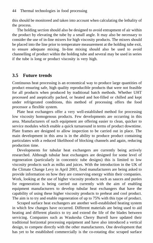
Continuous heat processing is an economical way to produce large quantities ofproduct ensuring safe, high quality reproducible products that were not feasiblefor all products when produced by traditional batch methods. Whether UHTprocessed and aseptically packed, or heated and hot-filled or chilled and keptunder refrigerated conditions, this method of processing offers the foodprocessor a flexible system.
Plate heat exchangers offer a very well-established method for processinglow viscosity homogenous products. Few developments are occurring in thisarea. Manufacturers of such equipment are offering easier to clean, quicker toservice modules which enable a quick turnaround in terms of product downtime.Plate frames are designed to allow inspection to be carried out in place. Themain development in this area is in the ability to produce product containingparticulates with a reduced likelihood of blocking channels and again, reducingproduction time.
Developments for tubular heat exchangers are currently being activelyresearched. Although tubular heat exchangers are designed for some level ofregeneration (particularly in concentric tube designs) this is limited to lowviscosity products such as milks and juices. With the introduction in the UK ofthe Climate Change Levy in April 2001, food manufacturers are being asked toprovide information on how they are conserving energy within their companies.Work, looking at the use of higher viscosity products such as sauces and pureesfor regeneration is being carried out currently with the aim of enablingequipment manufacturers to develop tubular heat exchangers that have thecapability of using these higher viscosity products to preheat and cool product.The aim is to try and enable regeneration of up to 75% with this type of product.
Scraped surface heat exchangers are another well-established heating systemin which few changes have occurred. Different materials are being used to aidheating and different plastics to try and extend the life of the blades betweenservicing. Companies such as Waukesha Cherry Burrell have updated theirtraditional horizontal processing equipment and have also introduced a verticaldesign, to compete directly with the other manufacturers. One development thathas yet to be established commercially is the co-rotating disc scraped surface
44 Thermal technologies in food processing
heat exchanger (CDHE). Having a rotating heating surface and a stationaryscraping device this system claims a high heat transfer capacity having heattransfer coefficients as high as 600 W/m2K when processing viscous fluids. TheCDHE develops large zones of reverse flow in the processing chamber soimproving mixing in the chamber and improving heat transfer. The work carriedout by the University of Denmark outlines that when placing several processingchambers in series the CDHE has great potential specifically for UHTprocessing of foods showing pseudoplastic behaviour and also particulate foods.
Direct heating systems are also fairly static in terms of development beingwell-established systems. One of the areas where work is being carried out is inthe use of direct systems for processing particulate matter. As already stated,infusion chambers can handle products containing small particles (such as juicecells) and further work is being carried out. Much needs to be understood aboutthe method of heat transfer to the particles to ensure that on entry to the heatingchamber the centre of the particle also achieves the required heat process soensuring a safe product.
Other trends in this area do not refer to the traditional heating methodsalready discussed. There are other methods of continuous processing that arebeing used for both development and commercial purposes. Ohmic heating willbe discussed in a later chapter and so is not discussed here.
3.6 Sources of further information and advice
3.6.1 Equipment manufacturersFurther detailed information on specific designs of equipment is available fromthe manufacturers of the equipment. Major manufacturers that can offer help andadvice on types of exchangers suitable for specific processes are:
Tetra Pak Ltd., 1 Longwalk Road, Stockley Park, Uxbridge, Middlesex UB111DL, UKTel: +44 (0) 870 442 6000Fax: +44 (0) 870 442 6001Website: www.tetrapak.com
HRS Heat Exchangers Ltd., 10–12 Caxton Way, Watford Business Park,Watford, Hertfordshire WD1 8UA, UKTel: +44 (0) 1923 232335Fax: +44 (0) 1923 230266Website: www.hrs.co.uk
Waukesha Cherry Burrell, 2300 One First Union Center, 301 South CollegeStreet, Charlotte, NC 28202, USATel: +1 800 252 5200Fax: +1 800 252 5012Website: www.waukesha-cb.com
Continuous heat processing 45

FMC Food Tech. Food Processing Systems, Sint-Niklaas, BelgiumTel: +32 3 780 1211Fax: +32 3 777 7955Website: www.fmcfoodtech.com
APV Systems, 23 Gatwick Road, Crawley, West Sussex RH10 2JB, UKTel: +44 (0) 1293 527777Fax: +44 (0) 1293 552640Website: www.apv.com
3.6.2 Trade associationsTrade associations offer advice on equipment and processors in this area. Furtherinformation can be found from:
The Processing and Packaging Manufacturers Association (PPMA), NewProgress House, 34 Stafford Road, Wallingford, Surrey SM6 9AA, UKTel: +44 (0) 20 8773 8111Fax: +44 (0) 20 8773 0022Website: www.ppma.co.uk
The Dairy Trade Federation, 19 Cornwall Terrace, London NW1 4QP, UKTel: +44 (0) 20 7486 7244Fax: +44 (0) 20 7487 4734
3.6.3 Professional bodiesProfessional bodies offer information and publications in this area. Furtherinformation can be found from:
Institute of Food Science and Technology (IFST), 5 Cambridge Court, 210Shepherds Bush Road, London W6 7NJ, UKTel: +44 (0) 20 7603 6316Fax: +44 (0) 20 7602 9936Website: www.ifst.org
Institute of Food Technology (IFT), 221 N. LaSalle Street, Ste. 300, Chicago IL60601-1291, USATel: +1 312 782 8424Fax: +1 312 782 8348Website: www.ift.org
3.6.4 Research associations and universitiesSeveral universities and research associations can offer independent help andadvice on processes and problems with processes. Further information can befound from:
46 Thermal technologies in food processing

Campden and Chorleywood Food Research Association, Chipping Campden,Gloucestershire GL55 6LD, UKTel: +44 (0) 1386 842000Fax: +44 (0) 1386 842100Website: www.campden.co.uk
Reaseheath College, Nantwich, Cheshire CW5 6DF, UKTel: +44 (0) 1270 625131Fax: +44 (0) 1270 625665Website: www.reaseheath.ac.uk
University of Reading, Faculty of Agriculture and Food, Whiteknights, ReadingRG6 2AP, UKTel: +44 (0) 1189 318700Fax: +44 (0) 1189 310080Website: www.rdg.ac.uk
Milk Marque, Product Development Centre, Reaseheath, Nantwich, CheshireCW5 6TA, UKTel: +44 (0) 1270 611051Fax: +44 (0) 1270 611013Website: www.milkmarque.co.uk
School of Chemical Engineering, University of Birmingham, Edgbaston,Birmingham B15 2TT, UKTel: +44 (0) 121 414 5330Fax: +44 (0) 121 414 5324Website: www.bham.ac.uk
3.6.5 Further readingFor further background reading the following texts offer specific advice andinformation in specialised areas:
BURTON H, Ultra High Temperature Processing of Milk and Milk Products.London, Elsevier Applied Science, 1988.
HOLDSWORTH S D, Aseptic Processing and Packaging of Food Products.London, Elsevier Applied Science, 1992.
ROSE D, Guidelines for the processing and aseptic packaging of low acid foods.Part 1. Principles of design, installation and commissioning. CCFRATechnical Manual 11, 1986.
ROSE D, Guidelines for the processing and aseptic packaging of low acid foods.Part 2. CCFRA Technical Manual 11, 1987.
Continuous heat processing 47

3.7 References
BUCHNER N, Aseptic processing and packaging of food particulates. In: AsepticProcessing and Packaging of Particulate Foods. Ed. Willhoft, E M A,Glasgow, Blackie Academic and Professional, 1993.
BURTON H, Ultra High Temperature Processing of Milk and Milk Products.London, Elsevier Applied Science, 1988.
DAVID J R D, GRAVES R H, CARLSON, V R, Aseptic Processing and Packaging ofFood. A food industry perspective. Boca Raton, USA, CRC Press Inc,1996.
FRIIS A, ADLER-NISSEN J, ‘The co-rotating scraped surface heat exchanger forfood processing’. In: Advances in Aseptic Processing and PackagingTechnologies. Ed. Ohlsson, T, Goteborg, Sweden, Kompendiet, 1995.
NELSON P E, CHAMBERS J V, RODRIGUEZ J H, Principles of Aseptic Processing andPackaging. Washington DC, The Food Processors Institute, 1987.
ROSE D, Guidelines for the processing and packaging of low acid foods. Parts 1and 2. CCFRA Technical Manual 11, 1986, 1987.
48 Thermal technologies in food processing