3. foundation design loads
TRANSCRIPT

RECOMMENDED RESIDENTIAL CONSTRUCTION FOR COASTAL AREAS 3-1
3. Foundation Design LoadsThis chapter provides guidance on how to determine the magnitude
of the loads placed on a building by a particular natural hazard event
or a combination of events. The methods presented are intended to
serve as the basis of a methodology for applying the calculated loads
to the building during the design process.
The process for determining site-specific loads from natural hazards begins with identifying the building codes or engineering standards in place for the selected site (e.g., the International Building Code 2009 (IBC 2009) or ASCE 7-05, Minimum Design Loads for Buildings and Other
Structures), if model building codes and other building standards do not provide load determi-nation and design guidance for each of the hazards identified. In these instances, supplemental guidance such as FEMA 55 should be sought, the loads imposed by each of the identified haz-ards should be calculated, and the load combinations appropriate for the building site should be determined. The load combinations used in this manual are those specified by ASCE 7-05, the standard referenced by the IBC 2009. Either allowable stress design (ASD) or strength

3-2 BUILDING ON STRONG AND SAFE FOUNDATIONS
3 FOUNDATION DESIGN LOADS
design methods can be used to design a building. For this manual, all of the calculations, analy-ses, and load combinations presented are based on ASD. The use of strength design methods will require the designer to modify the design values to accommodate strength design concepts. Assumptions utilized in this manual can be found in Appendix C.
3.1 Wind Loads
Wind loads on a building structure are calculated using the methodology presented in ASCE 7-05. This document is the wind standard referenced by the 2003 editions of the IBC and IRC. Equations used to calculate wind loads are presented in Appendix D.
The most important variable in calculating wind load is the design wind speed. Design wind speed can be obtained from the local building official or the ASCE 7-05 wind speed map (Fig-ure 3-1). The speeds shown in this figure are 3-second gust speeds for Exposure Category C at a 33-foot (10-meter) height. ASCE 7-05 includes scaling factors for other exposures and heights.
ASCE 7-05 specifies wind loads for structural components known as a main wind force re-sisting system (MWFRS). The foundation designs developed for this manual are based on MWFRS pressures calculated for Exposure Category C, the category with the highest antici-pated wind loads for land-based structures.
ASCE 7-05 also specifies wind loads for components and cladding (C&C). Components and cladding are considered part of the building envelope, and ASCE 7-05 requires C&C to be de-signed to resist higher wind pressures than a MWFRS.
3.2 Flood Loads
This manual develops in more detail flood load calculations and incorporates the methodol-ogy presented in ASCE 7-05. Although wind loads can directly affect a structure and dictate the actual foundation design, the foundation is more affected by flood loads. ASCE 24-05
discusses floodproof construction. Loads developed in ASCE 24-05 come directly from ASCE 7-05, which is what the designs presented herein are based upon.
The effects of flood loads on buildings can be exacerbated by storm-induced erosion and lo-calized scour, and by long-term erosion. Erosion and scour lower the ground surface around foundation members and can cause the loss of load-bearing capacity and resistance to lateral and uplift loads. Erosion and scour also increase flood depths and, therefore, increase depth dependent flood loads.
3.2.1 Design Flood and DFE
The design flood is defined by ASCE 7-05 as the greater of the following two flood events:
1. Base flood, affecting those areas identified as SFHAs on the community’s FIRM, or

3-3RECOMMENDED RESIDENTIAL CONSTRUCTION FOR COASTAL AREAS
FOUNDATION DESIGN LOADS 3
Fig
ure
3-1
.
Win
d s
peed
s (i
n m
ph
) fo
r th
e e
nti
re U
.S.
SO
UR
CE
: A
SC
E 7
-05

3-4 BUILDING ON STRONG AND SAFE FOUNDATIONS
3 FOUNDATION DESIGN LOADS
3.2.2 Design Stillwater Flood Depth (ds)
Design stillwater flood depth (ds) is the vertical distance between the eroded ground elevation and the stillwater flood elevation associated with the design flood. Determining the maximum
Figure 3-2.
Parameters that
determine or are
affected by flood
depth.
SOURCE: COASTAL
CONSTRUCTION
MANUAL
(FEMA 55)
2. The flood corresponding to the area designated as a flood hazard area on a community’s flood hazard map or otherwise legally designated.
The DFE is defined as the elevation of the design flood, including wave height and freeboard, relative to the datum specified on a community’s flood hazard map. Figure 3-2 shows the param-eters that determine or are affected by flood depth.

3-5RECOMMENDED RESIDENTIAL CONSTRUCTION FOR COASTAL AREAS
FOUNDATION DESIGN LOADS 3
design stillwater flood depth over the life of a building is the single most important flood load calculation that will be made; nearly all other coastal flood load parameters or calculations (e.g., hydrostatic load, design flood velocity, hydrodynamic load, design wave height, DFE, debris im-pact load, local scour depth) depend directly or indirectly on the design stillwater flood depth. The design stillwater flood depth (ds) is defined as:
ds = Esw – GS
Where
ds = Design stillwater flood depth (ft)
Esw = Design stillwater flood elevation (ft) above the datum (e.g., National Geodetic Ver-tical Datum [NGVD], North American Vertical Datum [NAVD]), including wave setup effects
GS = Lowest eroded ground elevation above datum (ft), adjacent to building, including the effects of localized sour around piles
GS is not the lowest existing pre-flood ground surface; it is the lowest ground surface that will result from long-term erosion and the amount of erosion expected to occur during a design flood, excluding local scour effects. The process for determining GS is described in Chapter 7 of FEMA 55.
Values for Esw are not shown on a FIRM, but they are given in the Flood Insurance Study (FIS) report, which is produced in conjunction with the FIRM for a community. FIS reports are usu-ally available from community officials, from NFIP State Coordinating Agencies, and on the web at the FEMA Map Service Center (http://store.msc.fema.gov). Some States have FIS reports available on their individual web sites.
3.2.3 Design Wave Height (Hb)
The design wave height at a coastal building site will be one of the most important design pa-rameters. Therefore, unless detailed analysis shows that natural or manmade obstructions will protect the site during a design event, wave heights at a site will be calculated from Equation 5-2 of ASCE 7-05 as the heights of depth-limited breaking waves (Hb), which are equivalent to 0.78 times the design stillwater flood depth:
Hb = 0.78ds
Note: 70 percent of the breaking wave height (0.7Hb) lies above the stillwater flood level.
3.2.4 Design Flood Velocity (V)
Estimating design flood velocities in coastal flood hazard areas is subject to considerable un-certainty. Little reliable historical information exists concerning the velocity of floodwaters during coastal flood events. The direction and velocity of floodwaters can vary significantly

3-6 BUILDING ON STRONG AND SAFE FOUNDATIONS
3 FOUNDATION DESIGN LOADS
throughout a coastal flood event, approaching a site from one direction during the beginning of the flood event before shifting to another (or several directions). Floodwaters can inundate some low-lying coastal sites from both the front (e.g., ocean) and the back (e.g., bay, sound, river). In a similar manner, flow velocities can vary from close to zero to high velocities during a single flood event. For these reasons, flood velocities should be estimated conservatively by assuming that floodwaters can approach from the most critical direction and that flow veloci-ties can be high.
For design purposes, the Commentary of ASCE 7-05 suggested a range of flood velocities from:
V = ds ÷ t (expected lower bound)
to
V = (gds)0.5 (expected upper bound)
Where
V = Average velocity of water in ft/s
ds = Design stillwater flood depth
t = Time (1 second)
g = Gravitational constant (32.2 ft/sec2)
Factors that should be considered before selecting the upper- or lower-bound flood velocity for design include:
Flood zone
Topography and slope
Distance from the source of flooding
Proximity to other buildings or obstructions
The upper bound should be taken as the design flood velocity if the building site is near the flood source, in a V zone, in an AO zone adjacent to a V zone, in an A zone subject to velocity flow and wave action, steeply sloping, or adjacent to other buildings or obstructions that will confine floodwaters and accelerate flood velocities. The lower bound is a more appropriate de-sign flood velocity if the site is distant from the flood source, in an A zone, flat or gently sloping, or unaffected by other buildings or obstructions.
3.3 Hydrostatic Loads
Hydrostatic loads occur when standing or slowly moving water comes into contact with a building or building component. These loads can act laterally (pressure) or vertically (buoyancy).

3-7RECOMMENDED RESIDENTIAL CONSTRUCTION FOR COASTAL AREAS
FOUNDATION DESIGN LOADS 3
Lateral hydrostatic forces are generally not sufficient to cause deflection or displacement of a building or building component unless there is a substantial difference in water elevation on opposite sides of the building or component; therefore, the NFIP requires that floodwater openings be provided in vertical walls that form an enclosed space below the BFE for a building in an A zone.
Lateral hydrostatic force is calculated by the following:
fstat = ½ γ ds2
Where
fstat = Hydrostatic force per unit width (lb/ft) resulting from flooding against vertical element
γ = Specific weight of water (62.4 lb/ft3 for freshwater and 64 lb/ft3 for saltwater)
Vertical hydrostatic forces during design flood conditions are not generally a concern for prop-erly constructed and elevated coastal buildings. Buoyant or flotation forces on a building can be of concern if the actual stillwater flood depth exceeds the design stillwater flood depth.
Vertical (buoyancy) hydrostatic force is calculated by the following:
FBuoy = γ (Vol)
Where
FBuoy = vertical hydrostatic force (lb) resulting from the displacement of a given volume of floodwater
Vol = volume of floodwater displaced by a submerged object (ft3) = displaced area x depth of flooding
Buoyant force acting on an object must be resisted by the weight of the object and any other op-posing force (e.g., anchorage forces) resisting flotation. In the case of a building, the live load on floors should not be counted on to resist buoyant forces.
3.4 Wave Loads
Calculating wave loads requires information about expected wave heights. For the purpos-es of this manual, the calculations will be limited by water depths at the site of interest. Wave forces can be separated into four categories:
Non-breaking waves (can usually be computed as hydrostatic forces against walls and hydro-dynamic forces against piles)
3-8 BUILDING ON STRONG AND SAFE FOUNDATIONS
3 FOUNDATION DESIGN LOADS
Breaking waves (short duration but large magnitude forces against walls and piles)
Broken waves (similar to hydrodynamic forces caused by flowing or surging water)
Uplift (often caused by wave runup, deflection, or peaking against the underside of hori-zontal surfaces)
Of these four categories, the forces from breaking waves are the largest and produce the most severe loads. Therefore, it is strongly recommended that the breaking wave load be used as the design wave load.
Two breaking wave loading conditions are of interest in residential construction: waves breaking on small-diameter vertical elements below the DFE (e.g., piles, columns in the foundation of a building in a V zone) and waves breaking against vertical walls below the DFE (e.g., solid foun-dation walls in A zones, breakaway walls in V zones).
3.4.1 Breaking Wave Loads on Vertical Piles
The breaking wave load (Fbrkp) on a pile can be assumed to act at the stillwater flood level and is calculated by Equation 5-4 from ASCE 7-05:
Fbrkp = (1/2)CDγDHb2
Where
Fbrkp = Net wave force (lb)
CD = Coefficient of drag for breaking waves = 1.75 for round piles or column, and 2.25 for square piles or columns
γ = Specific weight of water (lb/ft3)
D = Pile or column diameter (ft) for circular section. For a square pile or column, 1.4 times the width of the pile or column (ft).
Hb = Breaking wave height (ft)
3.4.2 Breaking Wave Loads on Vertical Walls
The net force resulting from a normally incident breaking wave (depth limited in size, with Hb = 0.78ds) acting on a rigid vertical wall, can be calculated by Equation 5-6 from ASCE 7-05:
Fbrkw = 1.1Cpγds2 + 2.4γds
2
Where
Fbrkw = net breaking wave force per unit length of structure (lb/ft) acting near the stillwater flood elevation
3-9RECOMMENDED RESIDENTIAL CONSTRUCTION FOR COASTAL AREAS
FOUNDATION DESIGN LOADS 3
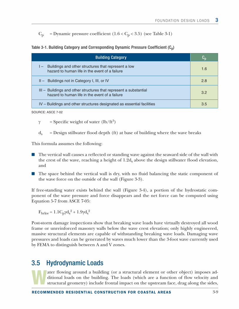
Cp = Dynamic pressure coefficient (1.6 < Cp < 3.5) (see Table 3-1)
Table 3-1. Building Category and Corresponding Dynamic Pressure Coefficient (Cp)
Building Category Cp
I – Buildings and other structures that represent a low
hazard to human life in the event of a failure1.6
II – Buildings not in Category I, III, or IV 2.8
III – Buildings and other structures that represent a substantial
hazard to human life in the event of a failure3.2
IV – Buildings and other structures designated as essential facilities 3.5
SOURCE: ASCE 7-02
γ = Specific weight of water (lb/ft3)
ds = Design stillwater flood depth (ft) at base of building where the wave breaks
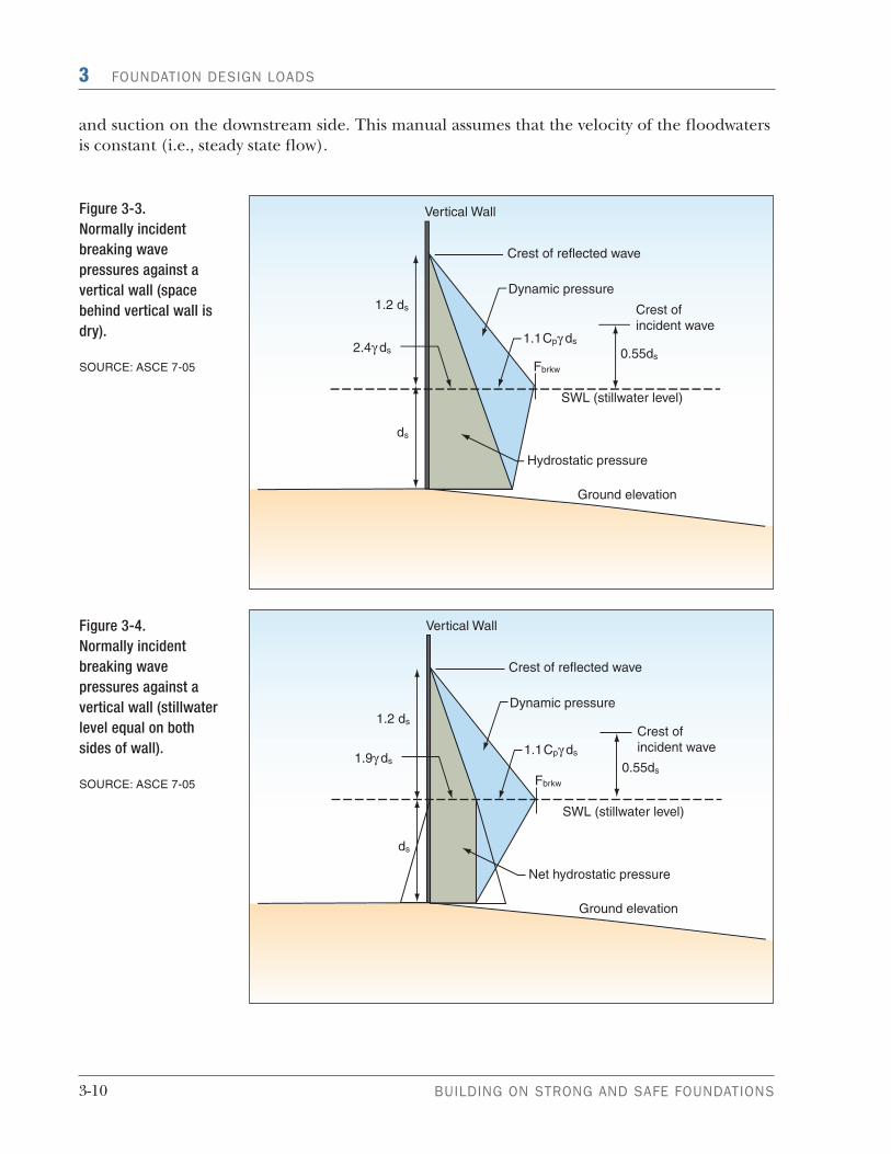
This formula assumes the following:
The vertical wall causes a reflected or standing wave against the seaward side of the wall with the crest of the wave, reaching a height of 1.2ds above the design stillwater flood elevation, and
The space behind the vertical wall is dry, with no fluid balancing the static component of the wave force on the outside of the wall (Figure 3-3).
If free-standing water exists behind the wall (Figure 3-4), a portion of the hydrostatic com-ponent of the wave pressure and force disappears and the net force can be computed using Equation 5-7 from ASCE 7-05:
Fbrkw = 1.1Cpγds2 + 1.9γds
2
Post-storm damage inspections show that breaking wave loads have virtually destroyed all wood frame or unreinforced masonry walls below the wave crest elevation; only highly engineered, massive structural elements are capable of withstanding breaking wave loads. Damaging wave pressures and loads can be generated by waves much lower than the 3-foot wave currently used by FEMA to distinguish between A and V zones.
3.5 Hydrodynamic Loads
Water flowing around a building (or a structural element or other object) imposes ad-ditional loads on the building. The loads (which are a function of flow velocity and structural geometry) include frontal impact on the upstream face, drag along the sides,
3-10 BUILDING ON STRONG AND SAFE FOUNDATIONS
3 FOUNDATION DESIGN LOADS
Figure 3-4.
Normally incident
breaking wave
pressures against a
vertical wall (stillwater
level equal on both
sides of wall).
SOURCE: ASCE 7-05
Figure 3-3.
Normally incident
breaking wave
pressures against a
vertical wall (space
behind vertical wall is
dry).
SOURCE: ASCE 7-05
and suction on the downstream side. This manual assumes that the velocity of the floodwaters is constant (i.e., steady state flow).
3-11RECOMMENDED RESIDENTIAL CONSTRUCTION FOR COASTAL AREAS
FOUNDATION DESIGN LOADS 3
One of the most difficult steps in quantifying loads imposed by moving water is determining the expected flood velocity. Refer to Section 3.2.4 for guidance concerning design flood velocities.
The following equation from FEMA 55 can be used to calculate the hydrodynamic load from flows with velocity greater than 10 ft/sec:
Fdyn = ½Cd ρV2A
Where
Fdyn = Hydrodynamic force (lb) acting at the stillwater mid-depth (halfway between the stillwater elevation and the eroded ground surface)
Cd = Drag coefficient (recommended values are 2.0 for square or rectangular piles and 1.2 for round piles)
ρ = Mass density of fluid (1.94 slugs/ft3 for freshwater and 1.99 slugs/ft3 for saltwater)
V = Velocity of water (ft/sec)
A = Surface area of obstruction normal to flow (ft2)
Note that the use of this formula will provide the total force against a building of a given im-pacted surface area (A). Dividing the total force by either length or width would yield a force per unit length; dividing by “A” would yield a force per unit area.
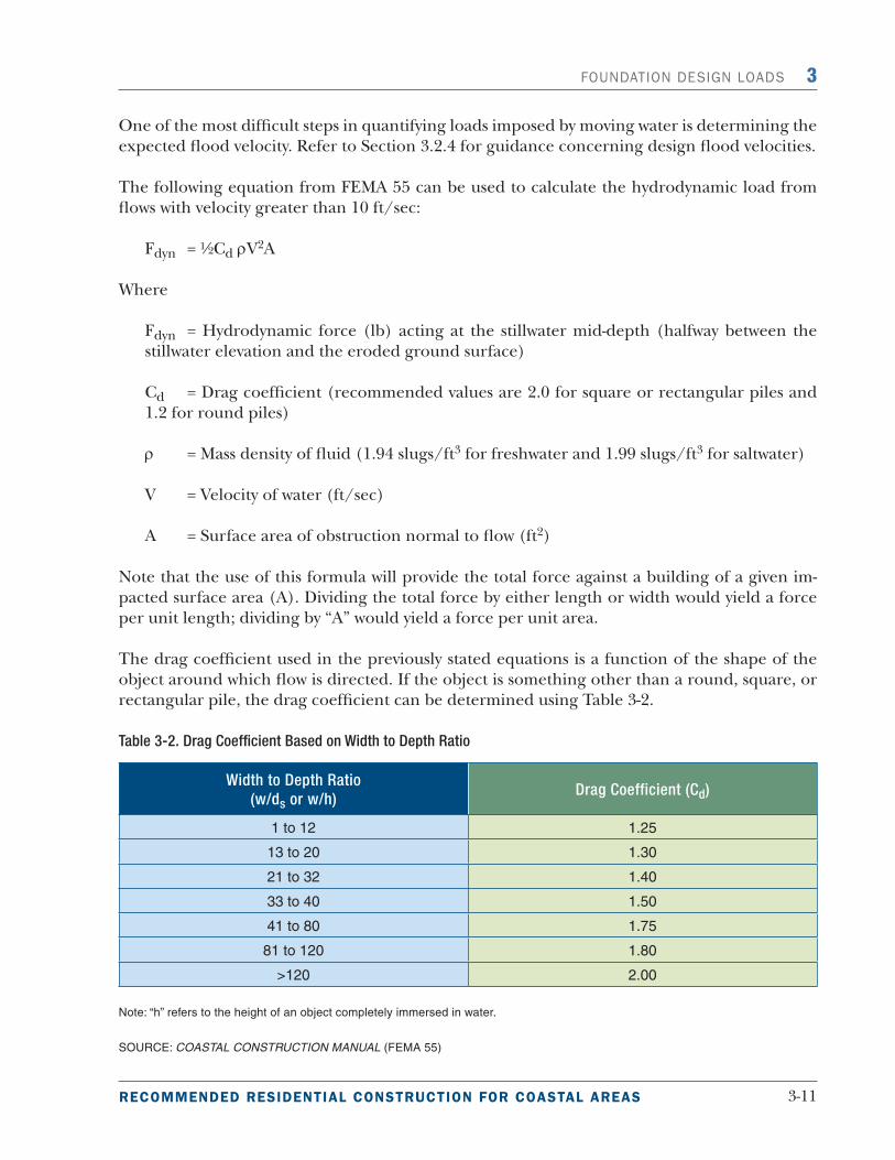
The drag coefficient used in the previously stated equations is a function of the shape of the object around which flow is directed. If the object is something other than a round, square, or rectangular pile, the drag coefficient can be determined using Table 3-2.
Table 3-2. Drag Coefficient Based on Width to Depth Ratio
Width to Depth Ratio
(w/ds or w/h)Drag Coefficient (Cd)
1 to 12 1.25
13 to 20 1.30
21 to 32 1.40
33 to 40 1.50
41 to 80 1.75
81 to 120 1.80
>120 2.00
Note: “h” refers to the height of an object completely immersed in water.
SOURCE: COASTAL CONSTRUCTION MANUAL (FEMA 55)

3-12 BUILDING ON STRONG AND SAFE FOUNDATIONS
3 FOUNDATION DESIGN LOADS
Flow around a building or building component will also create flow-perpendicular forces (lift forces). If the building component is rigid, lift forces can be assumed to be small. But if the building component is not rigid, lift forces can be greater than drag forces. The formula for lift force is similar to the formula for hydrodynamic force except that the drag coefficient (Cd) is replaced with the lift coefficient (Cl). For the purposes of this manual, the founda-tions of coastal residential buildings can be considered rigid, and hydrodynamic lift forces can therefore be ignored.
3.6 Debris Impact Loads
Debris or impact loads are imposed on a building by objects carried by moving water. The magnitude of these loads is very difficult to predict, yet some reasonable allowance must be made for them. The loads are influenced by where the building is located in the poten-
tial debris stream:
Immediately adjacent to or downstream from another building
Downstream from large floatable objects (e.g., exposed or minimally covered storage tanks)
Among closely spaced buildings
The following equation to calculate the magnitude of impact load is provided in the Commentary
of ASCE 7-05:
Fi = (πWVbCICOCDCBRmax) ÷ (2g∆t)
Where
Fi = Impact force acting at the stillwater level (lb)
π = 3.14
W = Weight of debris (lb), suggest using 1,000 if no site-specific information is available
Vb = Velocity of object (assume equal to velocity of water) (ft/sec)
CI = Importance coefficient (see Table C5-1 of ASCE 7-05)
CO = Orientation coefficient = 0.8
CD = Depth coefficient (see Table C5-2 and Figure C5-1 of ASCE 7-05)
CB = Blockage coefficient (see Table C5-3 and Figure C5-2 of ASCE 7-05)
Rmax= Maximum response ratio for impulsive load (see Table C5-4 of ASCE 7-05)

3-13RECOMMENDED RESIDENTIAL CONSTRUCTION FOR COASTAL AREAS
FOUNDATION DESIGN LOADS 3
g = Gravitational constant (32.2 ft/sec2)
∆t = Duration of impact (sec)
When the C coefficients and Rmax are set to 1.0, the above equation reduces to
Fi = (πWV) ÷ (2g∆t)
This equation is very similar to the equation provided in ASCE 7-98 and FEMA 55. The only dif-ference is the π/2 term, which results from the half-sine form of the impulse load.
The following uncertainties must be quantified before the impact of debris loading on the building can be determined using the above equation:
Size, shape, and weight (W) of the waterborne object
Flood velocity (V)
Velocity of the object compared to the flood velocity
Portion of the building that will be struck and most vulnerable to collapsing
Duration of the impact (t)
Once floodborne debris impact loads have been quantified, decisions must be made on how to apply them to the foundation and how to design foundation elements to resist them. For open foundations, the Coastal Construction Manual (FEMA 55) advises applying impact loading to a corner or critical column or pile concurrently with other flood loads (see FEMA 55, Table 11-6). For closed foundations (which are not recommended in Coastal A zones and are not allowed in V zones), FEMA 55 advises that the designer assume that one corner of the foundation will be destroyed by debris and recommends the foundation and the structure above be designed to contain redundancy to allow load redistribution to prevent collapse or localized failure. The following should be considered in determining debris impact loads:
Size, shape, and weight of the debris. It is recommended that, in the absence of information about the nature of the potential debris, a weight of 1,000 pounds be used for the debris weight (W). Objects of this weight could include portions of damaged buildings, utility poles, portions of previously embedded piles, and empty storage tanks.
Debris velocity. Flood velocity can be approximated by one of the equations discussed in Sec-tion 3.2.4. For the calculation of debris loads, the velocity of the waterborne object is assumed to be the same as the flood velocity. Note that, although this assumption may be accurate for small objects, it will overstate debris velocities for large objects (e.g., trees, logs, pier piles). The Com-
mentary of ASCE 7-05 provides guidance on estimating debris velocities for large debris.
Portion of building to be struck. The object is assumed to be at or near the water surface lev-el when it strikes the building. Therefore, the object is assumed to strike the building at the stillwater flood level.

3-14 BUILDING ON STRONG AND SAFE FOUNDATIONS
3 FOUNDATION DESIGN LOADS
Duration of impact. Uncertainty about the dura-tion of impact (∆t) (the time from initial impact, through the maximum deflection caused by the impact, to the time the object leaves) is the most likely cause of error in the calculation of debris impact loads. ASCE 7-05 showed that measured impact duration (from initial impact to time of maximum force) from laboratory tests varied from 0.01 to 0.05 second. The ASCE 7-05 recom-mended value for ∆t is 0.03 second.
3.7 Erosion and Localized Scour
Erosion is defined by Section 1-2 of ASCE 24-05 as the "wearing away of the land surface by detachment and movement of soil and
rock fragments, during a flood or storm or over a period of years, through the action of wind, wa-ter, or other geological processes." Section 7.5 of FEMA 55 describes erosion as “the wearing or washing away of coastal lands.” Since the exact configuration of the soil loss is important for foundation design purposes, a more specific defi-nition is used in this document (see the text box above and Figure 3-5).
Waves and currents during coastal flood conditions are capable of creating turbulence around foundation elements and causing localized scour, and the moving floodwaters can cause generalized erosion. Determining potential for localized scour and generalized erosion is critical in designing coastal foundations to ensure that failure during and after flooding does not occur as a result of the loss in either bearing capacity or anchoring resistance around
NOTE: The method for
determining debris impact
loads in ASCE 7-05 was
developed for riverine impact loads
and has not been evaluated for coastal
debris that may impact a building over
several wave cycles. Although these
impact loads are very large but of short
duration, a structural engineer should
be consulted to determine the structural
response to the short load duration (0.03
second recommended).
Erosion refers to a general lowering of
the ground surface over a wide area.
Scour refers to a localized loss of soil,
often around a foundation element.
Figure 3-5. Distinguishing between coastal erosion and scour. A building may be subject to either or both,
depending on the building location, soil characteristics, and flood conditions.
OriginalGround
Erosion Scour Erosionand Scour
OriginalGround
3-15RECOMMENDED RESIDENTIAL CONSTRUCTION FOR COASTAL AREAS
FOUNDATION DESIGN LOADS 3
the posts, piles, piers, columns, footings, or walls. Localized scour and generalized erosion determinations will require knowledge of the flood depth, flow conditions, soil characteristics, and foundation type.
In some locations, soil at or below the ground surface can be resistant to localized scour, and scour depths calculated below will be excessive. In instances where the designer believes the soil at a site will be scour-resistant, a geotechnical engineer should be consulted before calculated scour depths are reduced.
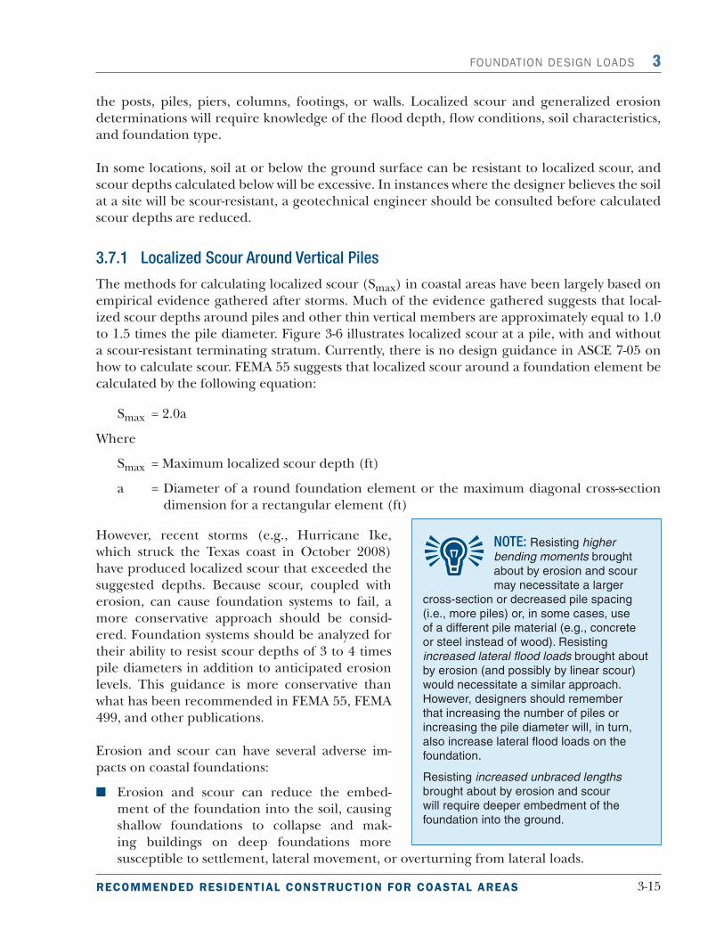
3.7.1 Localized Scour Around Vertical Piles
The methods for calculating localized scour (Smax) in coastal areas have been largely based on empirical evidence gathered after storms. Much of the evidence gathered suggests that local-ized scour depths around piles and other thin vertical members are approximately equal to 1.0 to 1.5 times the pile diameter. Figure 3-6 illustrates localized scour at a pile, with and without a scour-resistant terminating stratum. Currently, there is no design guidance in ASCE 7-05 on how to calculate scour. FEMA 55 suggests that localized scour around a foundation element be calculated by the following equation:
Smax = 2.0a
Where
Smax = Maximum localized scour depth (ft)
a = Diameter of a round foundation element or the maximum diagonal cross-section dimension for a rectangular element (ft)
However, recent storms (e.g., Hurricane Ike, which struck the Texas coast in October 2008) have produced localized scour that exceeded the suggested depths. Because scour, coupled with erosion, can cause foundation systems to fail, a more conservative approach should be consid-ered. Foundation systems should be analyzed for their ability to resist scour depths of 3 to 4 times pile diameters in addition to anticipated erosion levels. This guidance is more conservative than what has been recommended in FEMA 55, FEMA 499, and other publications.
Erosion and scour can have several adverse im-pacts on coastal foundations:
Erosion and scour can reduce the embed-ment of the foundation into the soil, causing shallow foundations to collapse and mak-ing buildings on deep foundations more susceptible to settlement, lateral movement, or overturning from lateral loads.
NOTE: Resisting higher
bending moments brought
about by erosion and scour
may necessitate a larger
cross-section or decreased pile spacing
(i.e., more piles) or, in some cases, use
of a different pile material (e.g., concrete
or steel instead of wood). Resisting
increased lateral flood loads brought about
by erosion (and possibly by linear scour)
would necessitate a similar approach.
However, designers should remember
that increasing the number of piles or
increasing the pile diameter will, in turn,
also increase lateral flood loads on the
foundation.
Resisting increased unbraced lengths
brought about by erosion and scour
will require deeper embedment of the
foundation into the ground.

3-16 BUILDING ON STRONG AND SAFE FOUNDATIONS
3 FOUNDATION DESIGN LOADS
Erosion and scour can increase the unbraced length of pile foundations, increase the bend-ing moment to which they are subjected, and overstress piles.
Erosion over a large area between a foundation and a flood source can expose the foun-dation to increased lateral flood loads (i.e., greater stillwater depths, possible higher wave heights, and higher flow velocities).
Local scour around individual piles will not generally expose foundations to greater flood loads, but scour across a building site may do so.
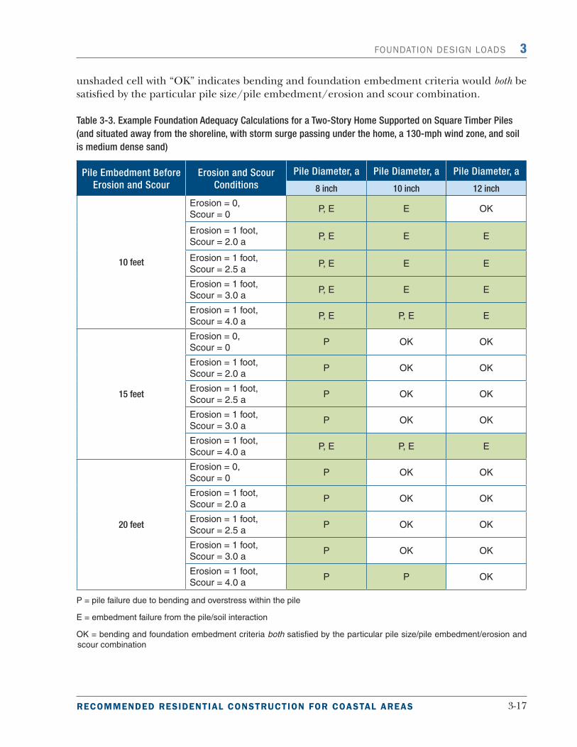
To illustrate these points, calculations were made to examine the effects of erosion and scour on foundation design for a simple case – a 32-foot x 32-foot two-story home (10-foot story height), situated away from the shoreline and elevated 8 feet above grade on 25 square timber piles (spaced 8 feet apart), on medium dense sand. The home was subjected to a design wind event with a 130-mph (3-second gust speed) wind speed and a 4-foot stillwater depth above the unerod-ed grade, with storm surge and broken waves passing under the elevated building. Lateral wind and flood loads were calculated in accordance with ASCE. For simplicity, the piles were ana-lyzed under lateral wind and flood loads only; dead, live, and wind uplift loads were neglected. If dead, live, and wind uplift loads were included in the analysis, deeper pile embedment and possibly larger piles may be needed.
Three different timber pile sizes (8-, 10-, and 12-inch square) were evaluated using pre-storm embedment depths of 10-, 15-, and 20-feet, and five different erosion and scour conditions (ero-sion = 0 or 1 foot; scour ranges from 2.0 times the pile diameter to 4.0 times the pile diameter). The results of the analysis are shown in Table 3-3. A shaded cell indicates the combination of pile size, pre-storm embedment, and erosion and scour would not provide the bending resistance and/or embedment required to resist the lateral loads imposed on them. The reason(s) for a foundation failure is indicated in each shaded cell, using “P” for pile failure due to bending and overstress within the pile and “E” for an embedment failure from the pile/soil interaction. An
Figure 3-6.
Scour at vertical
foundation member
stopped by underlying
scour-resistant
stratum.
SOURCE: COASTAL
CONSTRUCTION
MANUAL
(FEMA 55)
3-17RECOMMENDED RESIDENTIAL CONSTRUCTION FOR COASTAL AREAS
FOUNDATION DESIGN LOADS 3
unshaded cell with “OK” indicates bending and foundation embedment criteria would both be satisfied by the particular pile size/pile embedment/erosion and scour combination.
Table 3-3. Example Foundation Adequacy Calculations for a Two-Story Home Supported on Square Timber Piles
(and situated away from the shoreline, with storm surge passing under the home, a 130-mph wind zone, and soil
is medium dense sand)
Pile Embedment Before
Erosion and Scour
Erosion and Scour
Conditions
Pile Diameter, a Pile Diameter, a Pile Diameter, a
8 inch 10 inch 12 inch
10 feet
Erosion = 0,
Scour = 0P, E E OK
Erosion = 1 foot,
Scour = 2.0 aP, E E E
Erosion = 1 foot,
Scour = 2.5 aP, E E E
Erosion = 1 foot,
Scour = 3.0 aP, E E E
Erosion = 1 foot,
Scour = 4.0 aP, E P, E E
15 feet
Erosion = 0,
Scour = 0P OK OK
Erosion = 1 foot,
Scour = 2.0 aP OK OK
Erosion = 1 foot,
Scour = 2.5 aP OK OK
Erosion = 1 foot,
Scour = 3.0 aP OK OK
Erosion = 1 foot,
Scour = 4.0 aP, E P, E E
20 feet
Erosion = 0,
Scour = 0P OK OK
Erosion = 1 foot,
Scour = 2.0 aP OK OK
Erosion = 1 foot,
Scour = 2.5 aP OK OK
Erosion = 1 foot,
Scour = 3.0 aP OK OK
Erosion = 1 foot,
Scour = 4.0 aP P OK
P = pile failure due to bending and overstress within the pile
E = embedment failure from the pile/soil interaction
OK = bending and foundation embedment criteria both satisfied by the particular pile size/pile embedment/erosion and
scour combination

3-18 BUILDING ON STRONG AND SAFE FOUNDATIONS
3 FOUNDATION DESIGN LOADS
A review of Table 3-3 shows several key points:
Increasing pile embedment will not offset foundation inadequacy (bending failure) result-ing from too small a pile cross-section or too weak a pile material.
Increasing cross-section (or material strength) will not compensate for inadequate pile embedment.
Given the building and foundation configuration used in the example, the 8-inch square pile is not strong enough to resist the lateral loads resulting from the 130-mph design wind speed under any of the erosion and scour conditions evaluated, even if there is no erosion or scour. Homes supported by 8-inch square timber piles, with embedment depths of 10 feet or less, will likely fail in large numbers when subjected to design or near design loads and conditions. Homes supported by deeper 8-inch piles may still be lost during a design event due to pile (bending failures).
The 10-inch square pile is strong enough to resist bending under all but the most severe erosion and scour conditions analyzed.
The 12-inch pile is the only pile size evaluated that satisfies bending requirements under all erosion and scour conditions analyzed. This pile works with 10 feet of embedment under the no erosion and scour condition. However, introducing as little as 1 foot of erosion and scour equal to twice the pile diameter was enough to render the foundation too shallow.
Fifteen feet of pile embedment is adequate for both 10- and 12-inch piles subject to 1 foot of erosion and scour up to three times the pile diameter. However, when the scour is increased to four times the pile diameter (frequently observed following Hurricane Ike), 15 feet of embedment is inadequate for both piles. In general terms, approximately 11 feet of em-bedment is required in this example home to resist the loads and conditions after erosion and scour are imposed.
The 12-inch pile with 20 feet of embedment was the only foundation that worked under all erosion and scour conditions analyzed. This pile design may be justified for the example home analyzed when expected ero-sion and scour conditions are unknown or uncertain.
These analyses were based on only 1 foot of erosion, which historically is a relatively small amount. Many storms like Hurricanes Isabel, Ivan, and Ike caused much more extensive ero-sion. In some areas, these storms stripped away several feet of soil.
A foot of erosion is more damaging than a foot of scour. While scour reduces pile embedment and increases stresses within the pile, erosion reduces embedment, increases stresses, and, since it increases stillwater depths, it also increases the flood loads that the foundation must resist.
CAUTION: The results in Table
3-3 should not be used in lieu of
building- and site-specific engi-
neering analyses and foundation design. The
table is intended for illustrative purposes only
and is based upon certain assumptions and
simplifications, and for the combinations of
building characteristics, soil conditions, and
wind and flood conditions described above.
Registered design professionals should be
consulted for foundation designs.

3-19RECOMMENDED RESIDENTIAL CONSTRUCTION FOR COASTAL AREAS
FOUNDATION DESIGN LOADS 3
Table 3-3 suggests that increasing embedment beyond 15 feet is not necessary for 10- and 12-inch piles. This is only the case for relatively small amounts of erosion (like the 1 foot of erosion in the example). If erosion depths are greater, pile embedment must be increased.
3.7.2 Localized Scour Around Vertical Walls and Enclosures
Localized scour around vertical walls and enclosed areas (e.g., typical A zone construction) can be greater than that around vertical piles, and should be estimated using Table 3-4.
Table 3-4. Local Scour Depth as a Function of Soil Type
Soil Type Expected Depth (% of ds)
Loose sand 80
Dense sand 50
Soft silt 50
Stiff silt 25
Soft clay 25
Stiff clay 10
SOURCE: COASTAL CONSTRUCTION MANUAL (FEMA 55)
3.8 Flood Load Combinations
Load combinations (including those for flood loads) are given in ASCE 7-05, Sections 2.3.2 and 2.3.3 for strength design and Sections 2.4.1 and 2.4.2 for allowable stress design.
The basic load combinations are:
Allowable Stress Design
(1) D + F
(2) D + H + F + L + T
(3) D + H + F + (Lr or S or R)
(4) D + H + F + 0.75(L + T) + 0.75(Lr or S or R)
(5) D + H + F + (W or 0.7E)
(6) D + H + F + 0.75(W or 0.7E) + 0.75L + 1.5Fa + 0.75(Lr or S or R)
(7) 0.6D + W + H
(8) 0.6D + 0.7 E + H
3-20 BUILDING ON STRONG AND SAFE FOUNDATIONS
3 FOUNDATION DESIGN LOADS
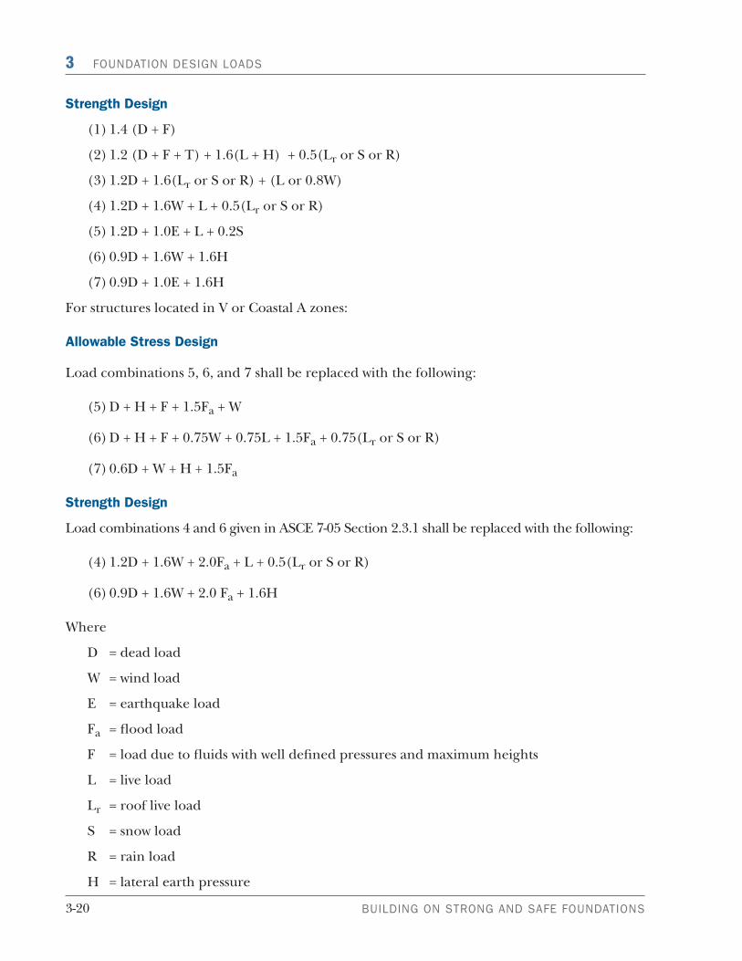
Strength Design
(1) 1.4 (D + F)
(2) 1.2 (D + F + T) + 1.6(L + H) + 0.5(Lr or S or R)
(3) 1.2D + 1.6(Lr or S or R) + (L or 0.8W)
(4) 1.2D + 1.6W + L + 0.5(Lr or S or R)
(5) 1.2D + 1.0E + L + 0.2S
(6) 0.9D + 1.6W + 1.6H
(7) 0.9D + 1.0E + 1.6H
For structures located in V or Coastal A zones:
Allowable Stress Design
Load combinations 5, 6, and 7 shall be replaced with the following:
(5) D + H + F + 1.5Fa + W
(6) D + H + F + 0.75W + 0.75L + 1.5Fa + 0.75(Lr or S or R)
(7) 0.6D + W + H + 1.5Fa
Strength Design
Load combinations 4 and 6 given in ASCE 7-05 Section 2.3.1 shall be replaced with the following:
(4) 1.2D + 1.6W + 2.0Fa + L + 0.5(Lr or S or R)
(6) 0.9D + 1.6W + 2.0 Fa + 1.6H
Where
D = dead load
W = wind load
E = earthquake load
Fa = flood load
F = load due to fluids with well defined pressures and maximum heights
L = live load
Lr = roof live load
S = snow load
R = rain load
H = lateral earth pressure

3-21RECOMMENDED RESIDENTIAL CONSTRUCTION FOR COASTAL AREAS
FOUNDATION DESIGN LOADS 3
Flood loads were included in the load combinations to account for the strong correlation be-tween flood and winds in hurricane-prone regions that run along the Gulf of Mexico and the Atlantic Coast.
In non-Coastal A zones, for ASD, replace the 1.5Fa with 0.75Fa in load combinations 5, 6, and 7 given above. For strength design, replace coefficients W and Fa in equations 4 and 6 above with 0.8 and 1.0, respectively.
Designers should be aware that not all of the flood loads will act at certain locations or against certain building types. Table 3-5 provides guidance to designers for the calculation of appropri-ate flood loads in V zones and Coastal A zones (non-Coastal A zone flood load combinations are shown for comparison).
The floodplain management regulations enacted by communities that participate in the NFIP prohibit the construction of solid perimeter wall foundations in V zones, but allow such founda-tions in A zones. Therefore, the designer should assume that breaking waves will impact piles in V zones and walls in A zones. It is generally unrealistic to assume that impact loads will occur on all piles at the same time as breaking wave loads; therefore, this manual recommends that impact loads be evaluated for strategic locations such as a building corner.
Table 3-5. Selection of Flood Load Combinations for Design
Case 1 Pile or Open Foundation in V Zone (Required)
Fbrkp (on all piles) + Fi (on one corner or critical pile only)
or
Fbrkp (on front row of piles only) + Fdyn (on all piles but front row) +Fi (on one corner or critical pile only)
Case 2 Pile or Open Foundation in Coastal A Zone (Recommended)
Fbrkp (on all piles) + Fi (on one corner or critical pile only)
or
Fbrkp (on front row of piles only) + Fdyn (on all piles but front row) +Fi (on one corner or critical pile only)
Case 3 Solid (Wall) Foundation in Coastal A Zone (NOT Recommended)
Fbrkp (on walls facing shoreline, including hydrostatic component) + Fdyn;
assume one corner is destroyed by debris, and design in redundancy
Case 4 Solid (Wall) Foundation in Non-Coastal A Zone (Shown for Comparison)
Fsta + Fdyn
SOURCE: COASTAL CONSTRUCTION MANUAL (FEMA 55)
