storage.spatiulconstruit.ro · 3 geze rwa geze rwa systems smoke and heat extraction systems (rwa)...
TRANSCRIPT
B E W E G U N G M I T S Y S T E M
SAFE T Y WITH VENTILATION POWERGEZE DRIVE TECHNOLOGY FOR
SMOKE AND HEAT EXTRACTION SYSTEMS (RWA)
G E Z E R WA A N D V E N T I L AT I O N T E C H N O LO G Y
3
GEZ
E RW
A
GEZE RWA systems
Smok
e an
d he
at
extr
actio
n sy
stem
s (R
WA
)
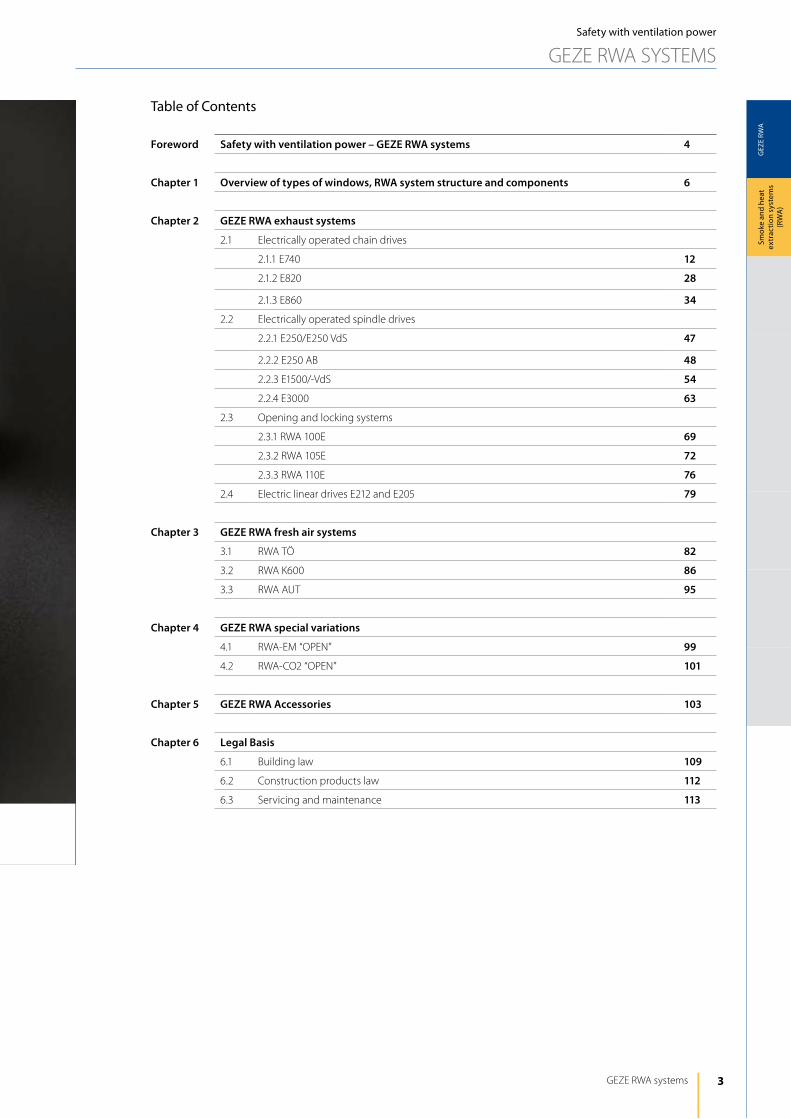
Table of Contents
Foreword Safety with ventilation power – GEZE RWA systems 4
Chapter 1 Overview of types of windows, RWA system structure and components 6
Chapter 2 GEZE RWA exhaust systems
2.1 Electrically operated chain drives
2.1.1 E740 12
2.1.2 E820 28
2.1.3 E860 34
2.2 Electrically operated spindle drives
2.2.1 E250/E250 VdS 47
2.2.2 E250 AB 48
2.2.3 E1500/-VdS 54
2.2.4 E3000 63
2.3 Opening and locking systems
2.3.1 RWA 100E 69
2.3.2 RWA 105E 72
2.3.3 RWA 110E 76
2.4 Electric linear drives E212 and E205 79
Chapter 3 GEZE RWA fresh air systems
3.1 RWA TÖ 82
3.2 RWA K600 86
3.3 RWA AUT 95
Chapter 4 GEZE RWA special variations
4.1 RWA-EM “OPEN” 99
4.2 RWA-CO2 “OPEN” 101
Chapter 5 GEZE RWA Accessories 103
Chapter 6 Legal Basis
6.1 Building law 109
6.2 Construction products law 112
6.3 Servicing and maintenance 113
Safety with ventilation power
GEZE RWA SySTEMS
4
GEZ
E RW
A
GEZE RWA ANd VENTilATiON TEChNOlOGy
Smok
e an
d he
at
extr
actio
n sy
stem
s (R
WA
)Safety with ventilation power
GEZE RWA SySTEMS
GEZE RWA systems – Safety with ventilation power
GEZE offers numerous opening and closing solutions for windows for a wide range of different application cases. The varied products on offer range from a large selection of drive systems for regular ventilation to complete fresh and exhaust air solutions for safe and fast natural smoke extraction (NRA) – safety with ventilation power.
We at GEZE attach great importance to all-round support – from planning through help with technical implementation through to servicing and maintenance.
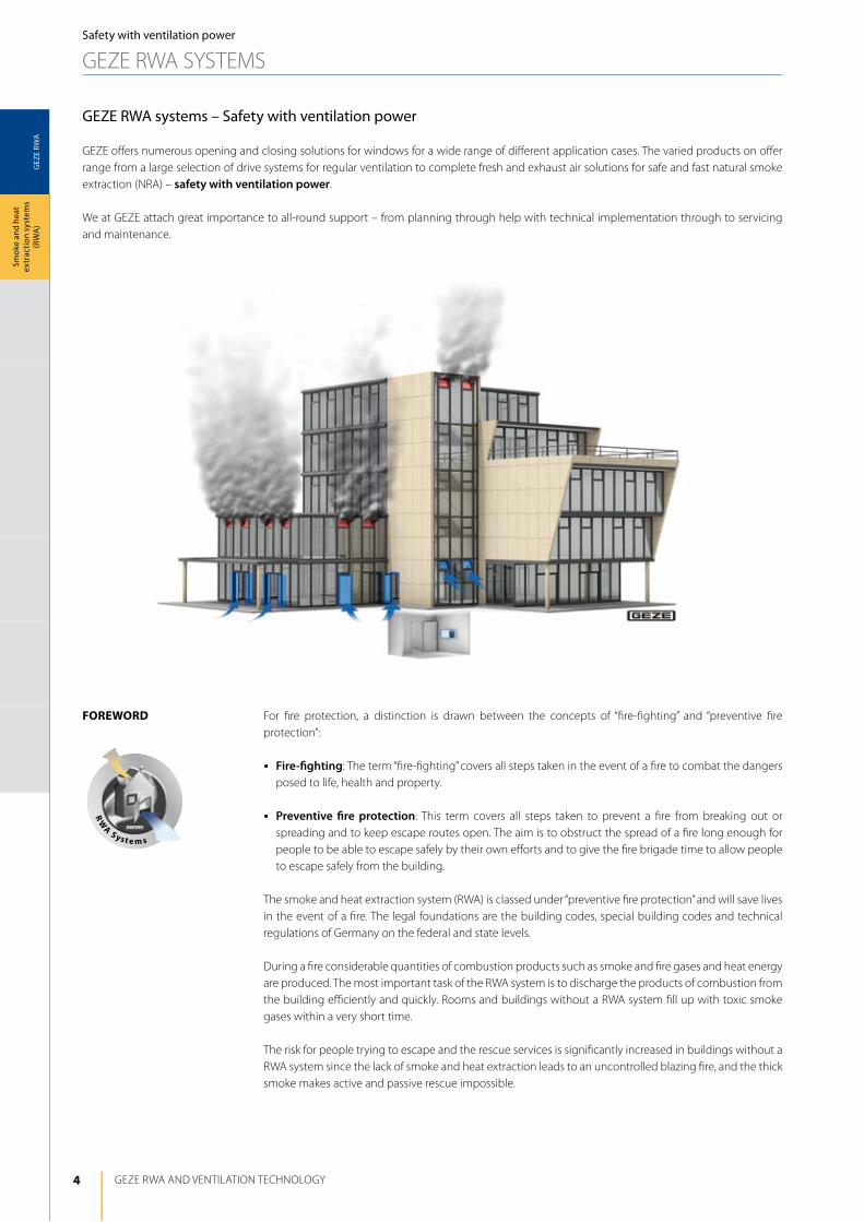
For fire protection, a distinction is drawn between the concepts of “fire-fighting” and “preventive fire protection”:
j Fire-fighting: The term “fire-fighting” covers all steps taken in the event of a fire to combat the dangers posed to life, health and property.
j Preventive fire protection: This term covers all steps taken to prevent a fire from breaking out or spreading and to keep escape routes open. The aim is to obstruct the spread of a fire long enough for people to be able to escape safely by their own efforts and to give the fire brigade time to allow people to escape safely from the building.
The smoke and heat extraction system (RWA) is classed under “preventive fire protection” and will save lives in the event of a fire. The legal foundations are the building codes, special building codes and technical regulations of Germany on the federal and state levels.
during a fire considerable quantities of combustion products such as smoke and fire gases and heat energy are produced. The most important task of the RWA system is to discharge the products of combustion from the building efficiently and quickly. Rooms and buildings without a RWA system fill up with toxic smoke gases within a very short time.
The risk for people trying to escape and the rescue services is significantly increased in buildings without a RWA system since the lack of smoke and heat extraction leads to an uncontrolled blazing fire, and the thick smoke makes active and passive rescue impossible.
Foreword
rw
A S yst e m s
5
GEZ
E RW
A
GEZE RWA systems
Smok
e an
d he
at
extr
actio
n sy
stem
s (R
WA
)
Safety with ventilation power
GEZE RWA SySTEMS
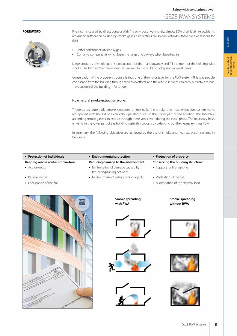
Smoke spreadingwithout RWA
Smoke spreadingwith RWA
Fire victims caused by direct contact with fire only occur very rarely; almost 90% of all fatal fire accidents are due to suffocation caused by smoke gases. “Fire victims are smoke victims” – there are two reasons for this:
j lethal constituents in smoky gasj Corrosive components which burn the lungs and airways when breathed in
large amounts of smoke gas rise on account of thermal buoyancy and fill the room or the building with smoke. The high ambient temperature can lead to the building collapsing in worst cases.
Conservation of the property structure is thus one of the major tasks for the RWA system. This way people can escape from the building through their own efforts, and the rescue services can carry out active rescue – evacuation of the building – for longer.
How natural smoke extraction works:
Triggered by automatic smoke detectors or manually, the smoke and heat extraction system vents are opened with the aid of electrically operated drives in the upper part of the building. The thermally ascending smoke gases can escape through these vents even during the initial phase. The necessary fresh air vents in the lower part of the building assist this process by balancing out the necessary mass flow.
in summary, the following objectives are achieved by the use of smoke and heat extraction systems in buildings:
Foreword
j Protection of individuals j Environmental protection j Protection of property
Keeping rescue routes smoke-free: Reducing damage to the environment: Conserving the building structure:j Active rescue j Minimisation of damage caused by
fire-extinguishing activities
j Support for fire-fighting
j Passive rescue j Minimum use of extinguishing agents j Ventilation of the fire
j localisation of the fire j Minimisation of the thermal load
rw
A S yst e m s
6
GEZ
E RW
A
GEZE RWA ANd VENTilATiON TEChNOlOGy
Smok
e an
d he
at
extr
actio
n sy
stem
s (R
WA
)
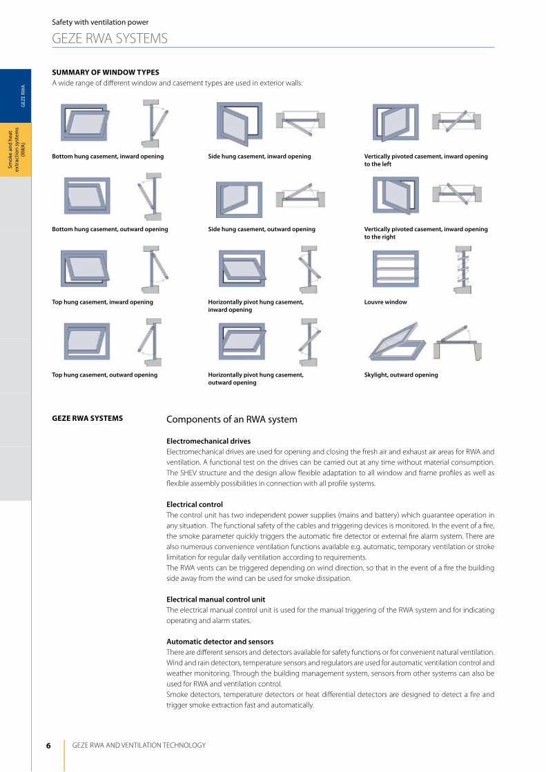
Components of an RWA system
Electromechanical drivesElectromechanical drives are used for opening and closing the fresh air and exhaust air areas for RWA and ventilation. A functional test on the drives can be carried out at any time without material consumption. The ShEV structure and the design allow flexible adaptation to all window and frame profiles as well as flexible assembly possibilities in connection with all profile systems.
Electrical controlThe control unit has two independent power supplies (mains and battery) which guarantee operation in any situation. The functional safety of the cables and triggering devices is monitored. in the event of a fire, the smoke parameter quickly triggers the automatic fire detector or external fire alarm system. There are also numerous convenience ventilation functions available e.g. automatic, temporary ventilation or stroke limitation for regular daily ventilation according to requirements. The RWA vents can be triggered depending on wind direction, so that in the event of a fire the building side away from the wind can be used for smoke dissipation.
Electrical manual control unitThe electrical manual control unit is used for the manual triggering of the RWA system and for indicating operating and alarm states.
Automatic detector and sensorsThere are different sensors and detectors available for safety functions or for convenient natural ventilation. Wind and rain detectors, temperature sensors and regulators are used for automatic ventilation control and weather monitoring. Through the building management system, sensors from other systems can also be used for RWA and ventilation control. Smoke detectors, temperature detectors or heat differential detectors are designed to detect a fire and trigger smoke extraction fast and automatically.
Safety with ventilation power
GEZE RWA SySTEMS
Bottom hung casement, inward opening
Bottom hung casement, outward opening
Top hung casement, inward opening
Top hung casement, outward opening
Side hung casement, inward opening
Side hung casement, outward opening
Horizontally pivot hung casement, inward opening
Horizontally pivot hung casement, outward opening
Vertically pivoted casement, inward opening to the left
Vertically pivoted casement, inward opening to the right
Louvre window
Skylight, outward opening
SummAry oF window typeSA wide range of different window and casement types are used in exterior walls:
geze rwA SyStemS
7
GEZ
E RW
A
MBZ300
GEZE RWA systems
Smok
e an
d he
at
extr
actio
n sy
stem
s (R
WA
)
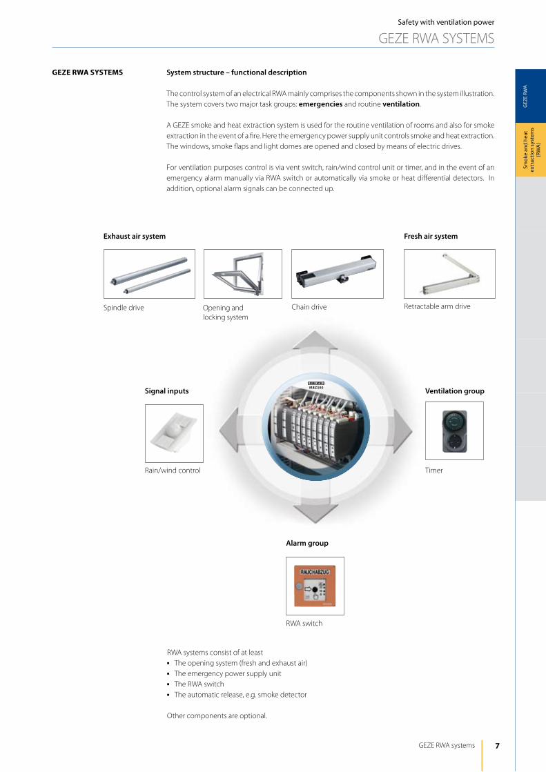
geze rwA SyStemS System structure – functional description
The control system of an electrical RWA mainly comprises the components shown in the system illustration. The system covers two major task groups: emergencies and routine ventilation.
A GEZE smoke and heat extraction system is used for the routine ventilation of rooms and also for smoke extraction in the event of a fire. here the emergency power supply unit controls smoke and heat extraction. The windows, smoke flaps and light domes are opened and closed by means of electric drives.
For ventilation purposes control is via vent switch, rain/wind control unit or timer, and in the event of an emergency alarm manually via RWA switch or automatically via smoke or heat differential detectors. in addition, optional alarm signals can be connected up.
RWA systems consist of at leastj The opening system (fresh and exhaust air)j The emergency power supply unitj The RWA switchj The automatic release, e.g. smoke detector
Other components are optional.
RWA switch
TimerRain/wind control
Chain drive
Exhaust air system Fresh air system
Spindle drive Retractable arm driveOpening and locking system
Ventilation groupSignal inputs
Alarm group
Safety with ventilation power
GEZE RWA SySTEMS
8
GEZ
E RW
A
1 2
1
2
2
130 LB17.5 17.5
1514.5
10
11
18 18
36
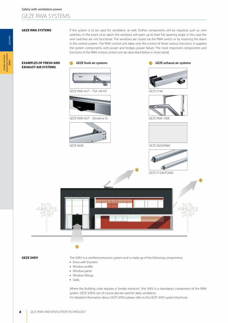
GEZE RWA AUT – TSA 160 NT
GEZE RWA 100E
GEZE E740
GEZE E820/E860
GEZE E1500/E3000
GEZE RWA AUT – Slimdrive Sl
GEZE K600
GEZE RWA ANd VENTilATiON TEChNOlOGy
Smok
e an
d he
at
extr
actio
n sy
stem
s (R
WA
)
geze rwA SyStemS
exAmpleS oF FreSh And exhAuSt Air SyStemS
geze SheV
if the system is to be used for ventilation as well, further components will be required, such as vent switches. in the event of an alarm the windows will open up to their full opening angle. in this case the vent switches are not functional. The windows are closed via the RWA switch or by resetting the alarm in the control system. The RWA control unit takes over the control of these various functions. it supplies the system components with power and bridges power failure. The most important components and functions of the RWA central control unit are described below in more detail.
The ShEV is a certified extraction system and is made up of the following components:j drive with bracketsj Window profilej Window panelj Window fittingsj Seals
Where the building code requires a “smoke extractor”, the ShEV is a mandatory component of the RWA system. GEZE ShEVs can of course also be used for daily ventilation. For detailed information about GEZE ShEVs please refer to the GEZE ShEV system brochure.
GEZE fresh air systems GEZE exhaust air systems
Safety with ventilation power
GEZE RWA SySTEMS
9
GEZ
E RW
A
GEZE RWA systems
Smok
e an
d he
at
extr
actio
n sy
stem
s (R
WA
)
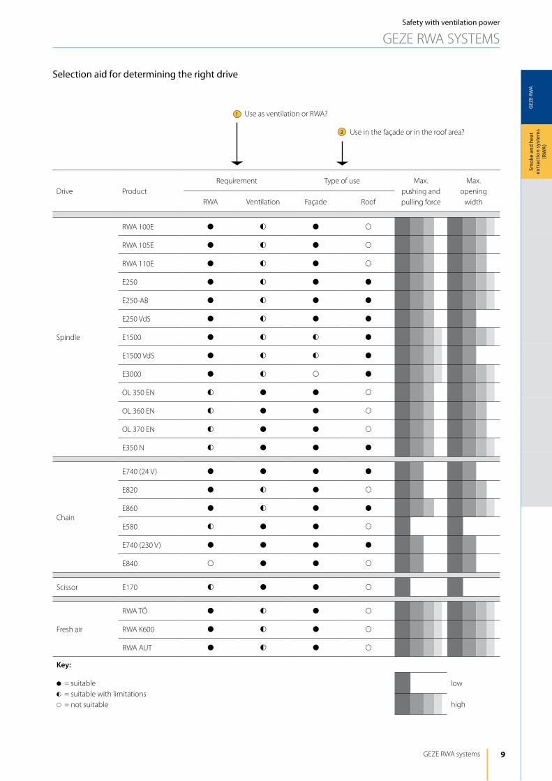
Use as ventilation or RWA?
Use in the façade or in the roof area?
drive ProductRequirement Type of use Max.
pushing and pulling force
Max. opening
widthRWA Ventilation Façade Roof
Spindle
RWA 100E d f d s
RWA 105E d f d s
RWA 110E d f d s
E250 d f d d
E250-AB d f d d
E250 VdS d f d d
E1500 d f f d
E1500 VdS d f f d
E3000 d f s d
Ol 350 EN f d d s
Ol 360 EN f d d s
Ol 370 EN f d d s
E350 N f d d d
Chain
E740 (24 V) d d d d
E820 d f d s
E860 d f d d
E580 f d d s
E740 (230 V) d d d d
E840 s d d s
Scissor E170 f d d s
Fresh air
RWA TÖ d f d s
RWA K600 d f d s
RWA AUT d f d s
Key:
d= suitablef= suitable with limitations s= not suitable
low
high
Selection aid for determining the right drive
1
2
Safety with ventilation power
GEZE RWA SySTEMS
10
GEZ
E RW
A
GEZE RWA ANd VENTilATiON TEChNOlOGy
Smok
e an
d he
at
extr
actio
n sy
stem
s (R
WA
)Safety with ventilation power
GEZE RWA SySTEMS
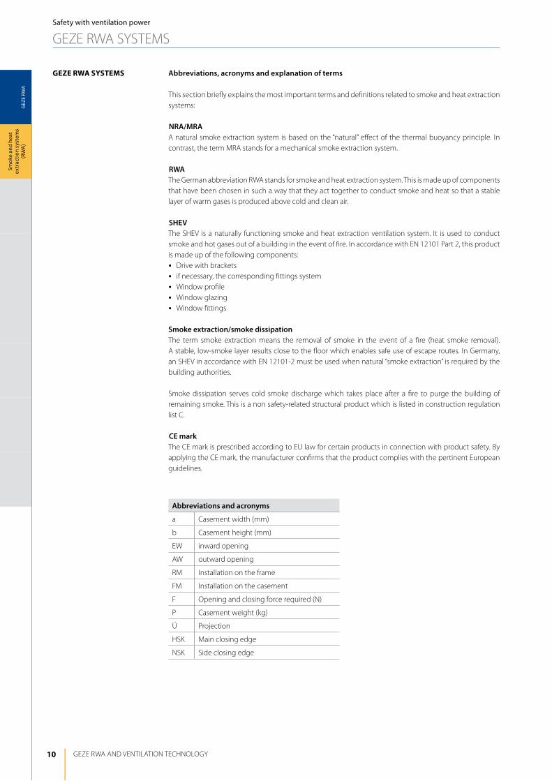
geze rwA SyStemS Abbreviations, acronyms and explanation of terms
This section briefly explains the most important terms and definitions related to smoke and heat extraction systems:
NRA/MRAA natural smoke extraction system is based on the “natural” effect of the thermal buoyancy principle. in contrast, the term MRA stands for a mechanical smoke extraction system.
RWAThe German abbreviation RWA stands for smoke and heat extraction system. This is made up of components that have been chosen in such a way that they act together to conduct smoke and heat so that a stable layer of warm gases is produced above cold and clean air.
SHEVThe ShEV is a naturally functioning smoke and heat extraction ventilation system. it is used to conduct smoke and hot gases out of a building in the event of fire. in accordance with EN 12101 Part 2, this product is made up of the following components:j drive with bracketsj if necessary, the corresponding fittings system j Window profilej Window glazingj Window fittings
Smoke extraction/smoke dissipationThe term smoke extraction means the removal of smoke in the event of a fire (heat smoke removal). A stable, low-smoke layer results close to the floor which enables safe use of escape routes. in Germany, an ShEV in accordance with EN 12101-2 must be used when natural “smoke extraction” is required by the building authorities.
Smoke dissipation serves cold smoke discharge which takes place after a fire to purge the building of remaining smoke. This is a non safety-related structural product which is listed in construction regulation list C.
CE markThe CE mark is prescribed according to EU law for certain products in connection with product safety. By applying the CE mark, the manufacturer confirms that the product complies with the pertinent European guidelines.
Abbreviations and acronyms
a Casement width (mm)
b Casement height (mm)
EW inward opening
AW outward opening
RM installation on the frame
FM installation on the casement
F Opening and closing force required (N)
P Casement weight (kg)
Ü Projection
hSK Main closing edge
NSK Side closing edge
11
GEZ
E RW
A
GEZE RWA systems
Smok
e an
d he
at
extr
actio
n sy
stem
s (R
WA
)
GEZE RWA exhaust systems
GEZE ElECTRiCAlly OPERATEd ChAiN dRiVES
GEZE RWA exhaust systems
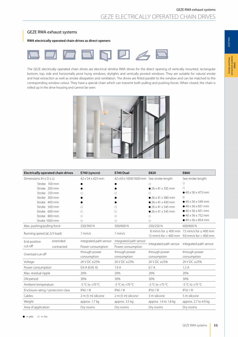
RWA electrically operated chain drives as direct openers
The GEZE electrically operated chain drives are electrical slimline RWA drives for the direct opening of vertically mounted, rectangular bottom, top, side and horizontally pivot hung windows, skylights and vertically pivoted windows. They are suitable for natural smoke and heat extraction as well as smoke dissipation and ventilation. The drives are fitted parallel to the window and can be matched to the corresponding window colour. They have a special chain which can transmit both pulling and pushing forces. When closed, the chain is rolled up in the drive housing and cannot be seen.
Electrically operated chain drives E740 (syncro) E740 Dual E820 E860
dimensions (h x d x l): 42 x 54 x 423 mm 42 x 63 x 1000/1600 mm See stroke length: See stroke length:
Stroke 100 mmStroke 200 mmStroke 250 mmStroke 300 mmStroke 400 mmStroke 500 mmStroke 600 mmStroke 800 mmStroke 1000 mm
d
d
s
d
d
s
s
s
s
d
d
s
d
d
s
s
s
s
s
d26 x 41 x 335 mms
d26 x 41 x 380 mmd26 x 41 x 430 mmd26 x 41 x 545 mmd26 x 41 x 545 mms
s
s
s
d40 x 56 x 473 mmod40 x 56 x 549 mmd40 x 56 x 651 mmd40 x 56 x 651 mmd40 x 56 x 752 mmd40 x 56 x 854 mm
Max. pushing/pulling force 250/300 N 500/600 N 250/250 N 600/600 N
Running speed (at 2/3 load) 7 mm/s 7 mm/s8 mm/s for ≤ 400 mm
12 mm/s for > 400 mm7.5 mm/s for ≤ 400 mm9.0 mm/s for > 400 mm
End position cut-off
extended integrated path sensor integrated path sensorintegrated path sensor integrated path sensor
contracted Power consumption Power consumption
Overload cut-offthrough power consumption
through power consumption
through power consumption
through power consumption
Voltage 24 V dC ±25% 24 V dC ±25% 24 V dC ±25% 24 V dC ±25%
Power consumption 0.9 A (0.95 A) 1.9 A 0.7 A 1.2 A
Max. residual ripple 20% 20% 20% 20%
ON period 30% 30% 30% 30%
Ambient temperature -5 0C to +70 0C -5 0C to +70 0C -5 0C to +75 0C -5 0C to +75 0C
Enclosure rating / protection class iP42 / iii iP42 / iii iP32 / iii iP32 / iii
Cables 2 m (5 m) silicone 2 m (5 m) silicone 3 m silicone 5 m silicone
Weight approx. 1.7 kg approx. 3.5 kg approx. 1.4 to 1.8 kg approx. 2.7 to 4.9 kg
Area of application dry rooms dry rooms dry rooms dry rooms
d= yes s= no
12
GEZ
E RW
A
geze e740
GEZE RWA ANd VENTilATiON TEChNOlOGy
Smok
e an
d he
at
extr
actio
n sy
stem
s (R
WA
)GEZE RWA exhaust systems
GEZE ElECTRiCAlly OPERATEd ChAiN dRiVES
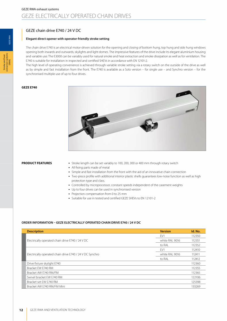
GEZE chain drive E740 / 24 V DC
Elegant direct opener with operator-friendly stroke setting
The chain drive E740 is an electrical motor-driven solution for the opening and closing of bottom hung, top hung and side hung windows opening both inwards and outwards, skylights and light domes. The impressive features of the drive include its elegant aluminium housing and variable use: The E3000 can be variably used for natural smoke and heat extraction and smoke dissipation as well as for ventilation. The E740 is suitable for installation in inspected and certified ShEVs in accordance with EN 12101-2. The high level of operating convenience is achieved through variable stroke setting via a rotary switch on the outside of the drive as well as by simple and fast installation from the front. The E740 is available as a Solo version – for single use – and Synchro version – for the synchronised multiple use of up to four drives.
j Stroke length can be set variably to 100, 200, 300 or 400 mm through rotary switchj All fixing parts made of metalj Simple and fast installation from the front with the aid of an innovative chain connectionj Two-piece profile with additional interior plastic shells guarantees low-noise function as well as high
protection type and class.j Controlled by microprocessor, constant speeds independent of the casement weightsj Up to four drives can be used in synchronised versionj Projection compensation from 0 to 25 mmj Suitable for use in tested and certified GEZE ShEVs to EN 12101-2
product FeAtureS
Description Version Id. No.
Electrically operated chain drive E740 / 24 V dC
EV1 112350
white RAl 9016 112351
to RAl 112352
Electrically operated chain drive E740 / 24 V dC Synchro
EV1 112410
white RAl 9016 112411
to RAl 112412
drive fixture skylight E740 112360
Bracket EW E740 RM 112355
Bracket AW E740 RM/FM 112365
Swivel bracket EW E740 RM 122106
Bracket set EW E740 RM 125398
Bracket AW E740 RM/FM Mini 133269
ORDER INFORMATION – GEZE ELECTRICALLy OPERATED CHAIN DRIVE E740 / 24 V DC
13
GEZ
E RW
A
GEZE RWA systems
Smok
e an
d he
at
extr
actio
n sy
stem
s (R
WA
)
GEZE RWA exhaust systems
GEZE ElECTRiCAlly OPERATEd ChAiN dRiVES
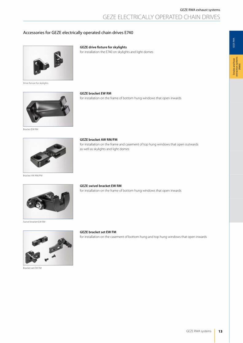
Accessories for GEZE electrically operated chain drives E740
GEZE bracket EW RMfor installation on the frame of bottom hung windows that open inwards
GEZE bracket AW RM/FMfor installation on the frame and casement of top hung windows that open outwardsas well as skylights and light domes
GEZE swivel bracket EW RMfor installation on the frame of bottom hung windows that open inwards
GEZE bracket set EW FMfor installation on the casement of bottom hung and top hung windows that open inwards
GEZE drive fixture for skylightsfor installation the E740 on skylights and light domes
drive fixture for skylights
Bracket set EW FM
Swivel bracket EW RM
Bracket AW RM/FM
Bracket EW RM
14
GEZ
E RW
A
423
206
412
54 70
42
a
GEZE RWA ANd VENTilATiON TEChNOlOGy
Smok
e an
d he
at
extr
actio
n sy
stem
s (R
WA
)
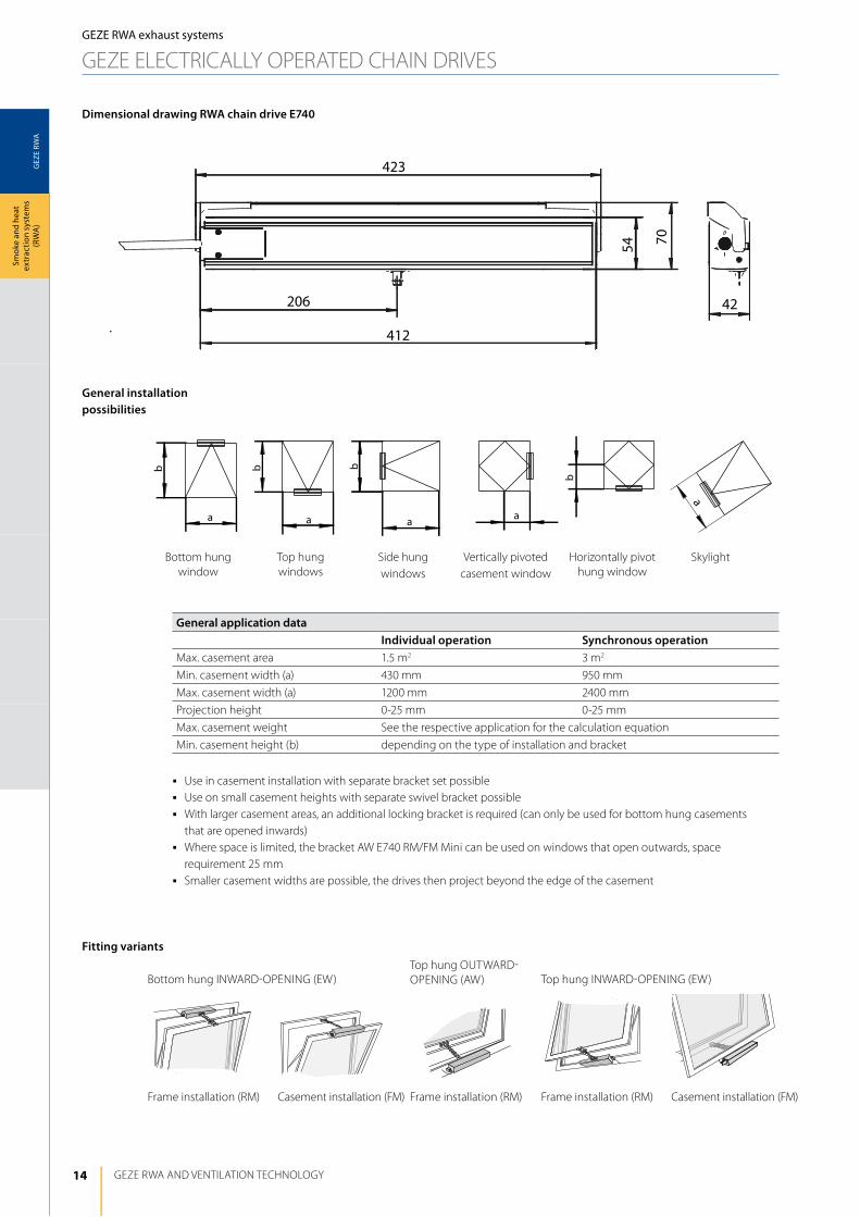
General installation possibilities
Fitting variants
General application dataIndividual operation Synchronous operation
Max. casement area 1.5 m2 3 m2
Min. casement width (a) 430 mm 950 mm
Max. casement width (a) 1200 mm 2400 mm
Projection height 0-25 mm 0-25 mm
Max. casement weight See the respective application for the calculation equation
Min. casement height (b) depending on the type of installation and bracket
j Use in casement installation with separate bracket set possiblej Use on small casement heights with separate swivel bracket possiblej With larger casement areas, an additional locking bracket is required (can only be used for bottom hung casements
that are opened inwards)j Where space is limited, the bracket AW E740 RM/FM Mini can be used on windows that open outwards, space
requirement 25 mmj Smaller casement widths are possible, the drives then project beyond the edge of the casement
GEZE RWA exhaust systems
GEZE ElECTRiCAlly OPERATEd ChAiN dRiVES
Dimensional drawing RWA chain drive E740
Bottom hung iNWARd-OPENiNG (EW)Top hung OUTWARd-OPENiNG (AW) Top hung iNWARd-OPENiNG (EW)
Frame installation (RM) Casement installation (FM) Frame installation (RM) Casement installation (FM)
Bottom hung window
Top hung windows
Side hung windows
Vertically pivoted casement window
horizontally pivot hung window
Skylight
Frame installation (RM)

15
GEZ
E RW
A
b
P
F
F
P
b
GEZE RWA systems
Smok
e an
d he
at
extr
actio
n sy
stem
s (R
WA
)
F =p x stroke x 0.68
b
Example for E740 in individual operation:
P = 25 kg = approx. 250 NStroke = 300 mmb = 1000 mm
F =250 x 300 x 0.68
F = 51 N1000
Example for two drives E740 Syncro:
P = 150 kg = approx. 1500 NStroke = 300 mmb = 1000 mm
F =1500 x 300 x 0.68
F = 306 N1000
Top hung windows
F max. = 250 N (individual operation)F max. = 500 N (synchronous operation)
Bottom hung window
F max. = 300 N (individual operation)F max. = 600 N (synchronous operation)
Equation for calculating opening and closing force:
Stroke
Stroke
Bracket Bracket Swivelling bracket Bracket set Drive fixtures
EW RM AW RM/FM EW RM EW FM Standard Skylight
Bottom hung case-ment, inward opening
d s d d d s
Top hung casement, outward opening
s d s s d s
Top hung casement, inward opening
d s s d d s
Skylight s d s s s d
d= yes s= no
rwA chain drive e740 on bottom hung and top hung windows that open inwards and outwards
Calculation of the area of application depending on casement weight and casement dimensionsPermissible wind loads must be taken into consideration!
Combination of brackets/type of installation
Key
F Opening and closing force required (N)
P Casement weight (kg)
Stroke Casement path/drive stroke (mm)
b Casement height (mm)
GEZE RWA exhaust systems
GEZE ElECTRiCAlly OPERATEd ChAiN dRiVES
16
GEZ
E RW
A
39028 28
25
58
38 21 32
423167167
390 390
25
3558
2128 32
167 167 167 167
GEZE RWA ANd VENTilATiON TEChNOlOGy
Smok
e an
d he
at
extr
actio
n sy
stem
s (R
WA
)
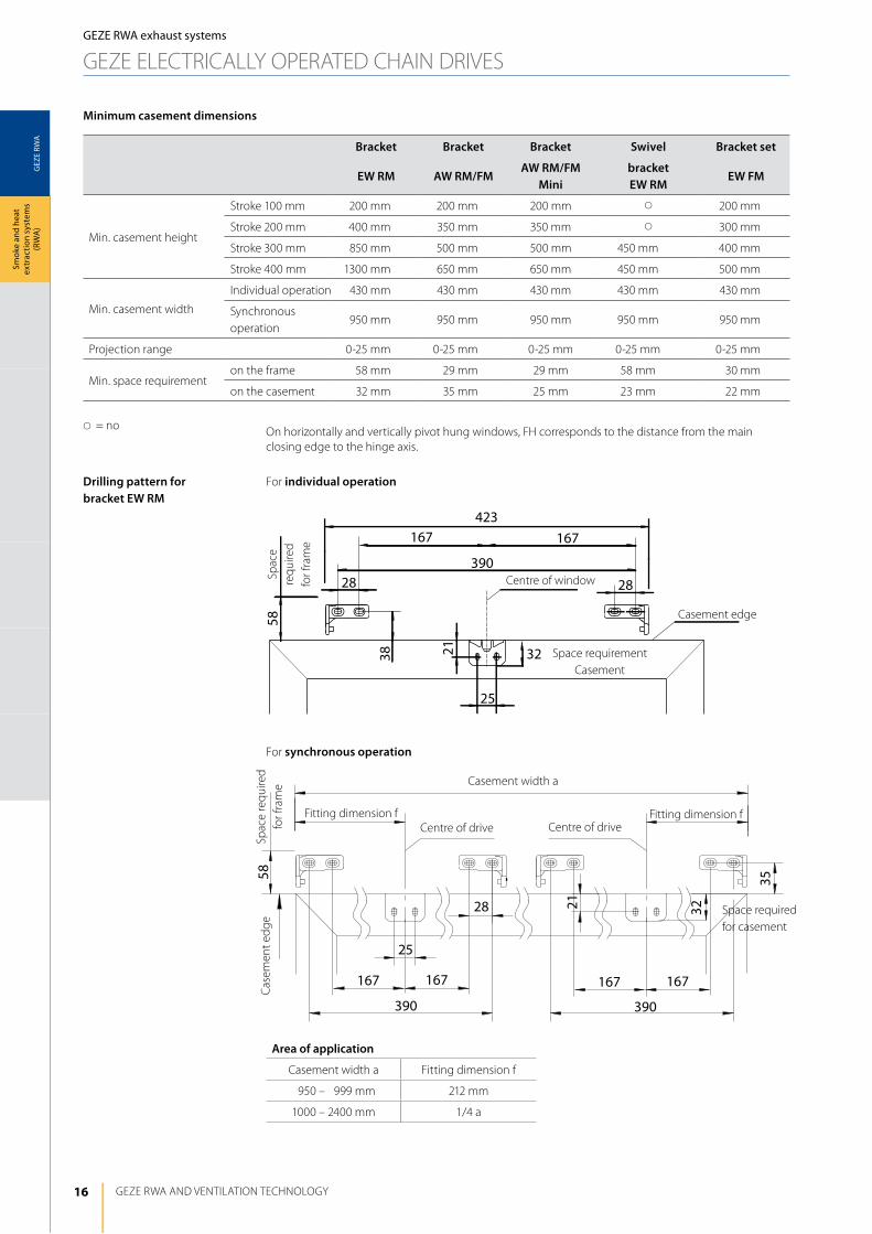
Bracket Bracket Bracket Swivel Bracket set
EW RM AW RM/FMAW RM/FM
Minibracket EW RM
EW FM
Min. casement height
Stroke 100 mm 200 mm 200 mm 200 mm s 200 mm
Stroke 200 mm 400 mm 350 mm 350 mm s 300 mm
Stroke 300 mm 850 mm 500 mm 500 mm 450 mm 400 mm
Stroke 400 mm 1300 mm 650 mm 650 mm 450 mm 500 mm
Min. casement width
individual operation 430 mm 430 mm 430 mm 430 mm 430 mm
Synchronous operation
950 mm 950 mm 950 mm 950 mm 950 mm
Projection range 0-25 mm 0-25 mm 0-25 mm 0-25 mm 0-25 mm
Min. space requirement on the frame 58 mm 29 mm 29 mm 58 mm 30 mm
on the casement 32 mm 35 mm 25 mm 23 mm 22 mm
s= no
For individual operation
On horizontally and vertically pivot hung windows, Fh corresponds to the distance from the main closing edge to the hinge axis.
For synchronous operation
Drilling pattern for bracket EW RM
Casement edge
Case
men
t edg
e
Centre of window
Centre of drive
Casement width a
Spac
e re
quire
d fo
r fra
me
Spac
e re
quire
d fo
r fra
me
Minimum casement dimensions
Centre of driveFitting dimension f Fitting dimension f
Area of application
Casement width a Fitting dimension f
1950 – 2999 mm 212 mm
1000 – 2400 mm 1/4 a
GEZE RWA exhaust systems
GEZE ElECTRiCAlly OPERATEd ChAiN dRiVES
Space requirementCasement
Space required for casement
17
GEZ
E RW
A
390390
29
21
44 28
35
167 16728
167 167
23
167167
38
2828
390
58
390
28 28
38
167 167
23
56 56
423 423
167
44
28 28
29
11 21 35
390167
23
167167
38
2828
390
58
56
423
GEZE RWA systems
Smok
e an
d he
at
extr
actio
n sy
stem
s (R
WA
)
For synchronous operation
For synchronous operation
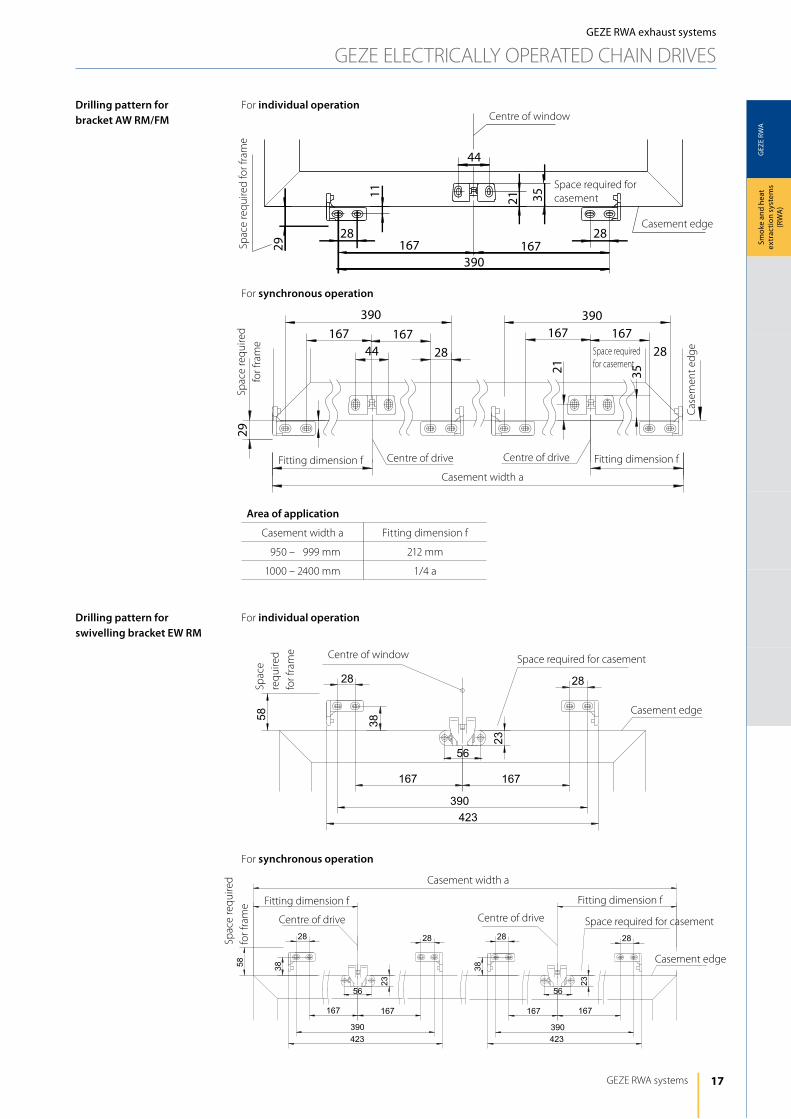
Drilling pattern for bracket AW RM/FM
Case
men
t edg
e
Centre of drive
Casement width a
Casement edge
Centre of window
Spac
e re
quire
d fo
r fra
me
For individual operation
For individual operation
Centre of driveFitting dimension f Fitting dimension f
Area of application
Casement width a Fitting dimension f
1950 – 2999 mm 212 mm
1000 – 2400 mm 1/4 a
Spac
e re
quire
d
for f
ram
e
Drilling pattern for swivelling bracket EW RM
GEZE RWA exhaust systems
GEZE ElECTRiCAlly OPERATEd ChAiN dRiVES
Space required for casement
Space required for casement
Casement width a
Spac
e re
quire
d
for f
ram
e Centre of window Space required for casement
Casement edge
Centre of drive Centre of drive Space required for casement
Casement edge
Fitting dimension fFitting dimension f
Spac
e re
quire
d fo
r fra
me

18
GEZ
E RW
A
390
2843,528
13 15,5
3022
1111
2222
12.5
167167 2828
29
25
390
2828 43.5
13
15.5
390
3022 2828 43.5
13
15.5
390
25
29 12.5
1111
2222
167167
28
28
28
28167 167
22 22
11
1112.5
390390
GEZE RWA ANd VENTilATiON TEChNOlOGy
Smok
e an
d he
at
extr
actio
n sy
stem
s (R
WA
)GEZE RWA exhaust systems
GEZE ElECTRiCAlly OPERATEd ChAiN dRiVES
For individual operation
For individual operation
Drilling pattern for bracket set EW RM
Drilling pattern for bracket AW RM/FM Mini
Casement edge
Centre of window
Space required for casement
Space required for frame
For synchronous operation
For synchronous operation
Area of application
Casement width a Fitting dimension f
1950 – 2999 mm 212 mm
1000 – 2400 mm 1/4 a
Casement edge
Casement width a
Centre of driveCentre of drive
Casement edge
Fitting dimension fFitting dimension f
Spac
e re
quire
d fo
r fra
me
Spac
e re
quire
d fo
r ca
sem
ent
Centre of casement
Spac
e re
quire
d fo
r fra
me
Spac
e re
quire
d fo
r cas
emen
t
Casement edge
Casement width a
Centre of driveCentre of drive
Casement edge
Fitting dimension fFitting dimension f
Spac
e re
quire
d fo
r fra
me
Spac
e re
quire
d fo
r cas
emen
t

19
GEZ
E RW
A
PF
4060
GEZE RWA systems
Smok
e an
d he
at
extr
actio
n sy
stem
s (R
WA
)
Bracket
AW RM/FM
Min. casement height
Stroke 100 mm 250 mm
Stroke 200 mm 450 mm
Stroke 300 mm 600 mm
Stroke 400 mm 750 mm
Min. casement width
individual operation
450 mm
Synchronous operation
1000 mm
Projection range 0-20 mm
Min. space requirement
on the frame 60 mm
on the casement 42 mm
Minimum casement dimensions
Min. casement heights depending on projection
j Min. casement height depends on projection and increases as projection increasesj Guideline values: installation can vary depending on the type of window
Cas
emen
t hei
ght u
p to
cen
tre
of h
inge
(mm
)
F = P x 0.68
Equation for calculating opening and closing force:
rwA chain drive e740 on skylight
Calculation of the area of application depending on casement weight and casement dimensionsPermissible wind loads must be taken into consideration!
Key
F drive force required for opening (N)
P Casement weight (kg)
Horizontal windows and light domes
F max. = 250 N (individual operation)F max. = 500 N (synchronous operation)
Example for E740 in individual operation:
P = 25 kg = approx. 250 N
F = 250 x 0.68 F = 170 N
Example for two drives E740 Syncro:
P = 60 kg = approx. 600 N
F = 600 x 0.68 F = 408 N
Max. stroke 100 mm
Max. stroke 200 mm
Max. stroke 300 mm
Max. stroke 400 mm
Projection (mm)
GEZE RWA exhaust systems
GEZE ElECTRiCAlly OPERATEd ChAiN dRiVES
Space required for casement
Space required for frame
20
GEZ
E RW
A
44
4821
18
218
436
218
436 436
218218
2148
44
GEZE RWA ANd VENTilATiON TEChNOlOGy
Smok
e an
d he
at
extr
actio
n sy
stem
s (R
WA
)
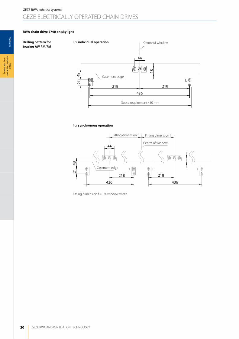
rwA chain drive e740 on skylight
For individual operationDrilling pattern for bracket AW RM/FM
Casement edge
Centre of window
Space requirement 450 mm
For synchronous operation
Fitting dimension f = 1/4 window width
Casement edge
Centre of window
Fitting dimension f Fitting dimension f
GEZE RWA exhaust systems
GEZE ElECTRiCAlly OPERATEd ChAiN dRiVES
21
GEZ
E RW
A
geze e740 duAl
GEZE RWA systems
Smok
e an
d he
at
extr
actio
n sy
stem
s (R
WA
)
GEZE RWA exhaust systems
GEZE ElECTRiCAlly OPERATEd ChAiN dRiVES
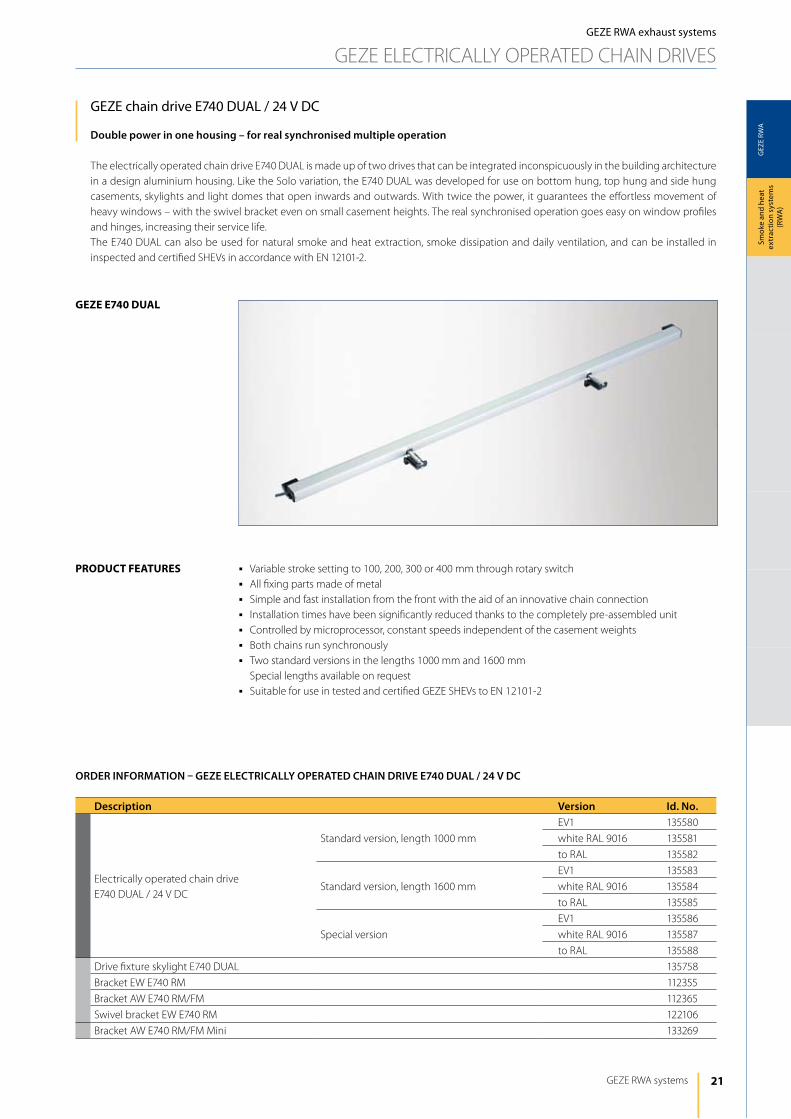
GEZE chain drive E740 DuAl / 24 V DC
Double power in one housing – for real synchronised multiple operation
The electrically operated chain drive E740 dUAl is made up of two drives that can be integrated inconspicuously in the building architecture in a design aluminium housing. like the Solo variation, the E740 dUAl was developed for use on bottom hung, top hung and side hung casements, skylights and light domes that open inwards and outwards. With twice the power, it guarantees the effortless movement of heavy windows – with the swivel bracket even on small casement heights. The real synchronised operation goes easy on window profiles and hinges, increasing their service life.The E740 dUAl can also be used for natural smoke and heat extraction, smoke dissipation and daily ventilation, and can be installed in inspected and certified ShEVs in accordance with EN 12101-2.
j Variable stroke setting to 100, 200, 300 or 400 mm through rotary switchj All fixing parts made of metalj Simple and fast installation from the front with the aid of an innovative chain connectionj installation times have been significantly reduced thanks to the completely pre-assembled unitj Controlled by microprocessor, constant speeds independent of the casement weightsj Both chains run synchronouslyj Two standard versions in the lengths 1000 mm and 1600 mm Special lengths available on requestj Suitable for use in tested and certified GEZE ShEVs to EN 12101-2
product FeAtureS
Description Version Id. No.
Electrically operated chain drive E740 dUAl / 24 V dC
Standard version, length 1000 mm
EV1 135580
white RAl 9016 135581
to RAl 135582
Standard version, length 1600 mm
EV1 135583
white RAl 9016 135584
to RAl 135585
Special version
EV1 135586
white RAl 9016 135587
to RAl 135588
drive fixture skylight E740 dUAl 135758
Bracket EW E740 RM 112355
Bracket AW E740 RM/FM 112365
Swivel bracket EW E740 RM 122106
Bracket AW E740 RM/FM Mini 133269
ORDER INFORMATION – GEZE ELECTRICALLy OPERATED CHAIN DRIVE E740 DUAL / 24 V DC
22
GEZ
E RW
A
GEZE RWA ANd VENTilATiON TEChNOlOGy
Smok
e an
d he
at
extr
actio
n sy
stem
s (R
WA
)GEZE RWA exhaust systems
GEZE ElECTRiCAlly OPERATEd ChAiN dRiVES
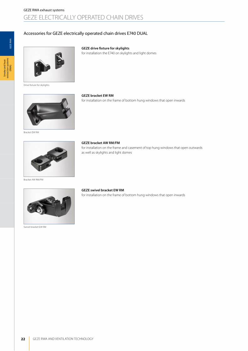
Accessories for GEZE electrically operated chain drives E740 DuAl
GEZE bracket EW RMfor installation on the frame of bottom hung windows that open inwards
GEZE bracket AW RM/FMfor installation on the frame and casement of top hung windows that open outwards as well as skylights and light domes
GEZE swivel bracket EW RMfor installation on the frame of bottom hung windows that open inwards
GEZE drive fixture for skylightsfor installation the E740 on skylights and light domes
drive fixture for skylights
Swivel bracket EW RM
Bracket AW RM/FM
Bracket EW RM
23
GEZ
E RW
A
L2
L1
KK
63 72
42
a
GEZE RWA systems
Smok
e an
d he
at
extr
actio
n sy
stem
s (R
WA
)
GEZE RWA exhaust systems
GEZE ElECTRiCAlly OPERATEd ChAiN dRiVES
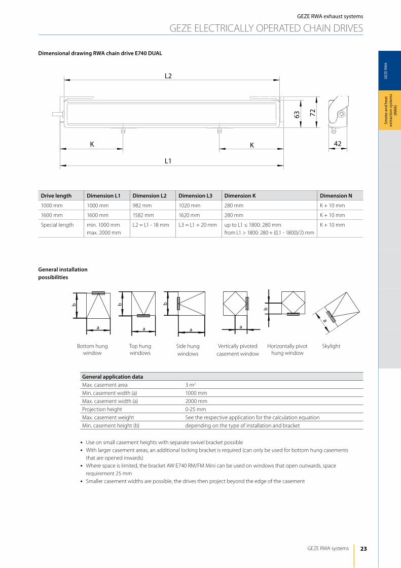
Dimensional drawing RWA chain drive E740 DUAL
Drive length Dimension L1 Dimension L2 Dimension L3 Dimension K Dimension N
1000 mm 1000 mm 982 mm 1020 mm 280 mm K + 10 mm
1600 mm 1600 mm 1582 mm 1620 mm 280 mm K + 10 mm
Special length min. 1000 mmmax. 2000 mm
l2 = l1 - 18 mm l3 = l1 + 20 mm up to l1 ≤ 1800: 280 mmfrom l1 > 1800: 280 + ((l1 - 1800)/2) mm
K + 10 mm
General application dataMax. casement area 3 m2
Min. casement width (a) 1000 mm
Max. casement width (a) 2000 mm
Projection height 0-25 mm
Max. casement weight See the respective application for the calculation equation
Min. casement height (b) depending on the type of installation and bracket
j Use on small casement heights with separate swivel bracket possiblej With larger casement areas, an additional locking bracket is required (can only be used for bottom hung casements
that are opened inwards)j Where space is limited, the bracket AW E740 RM/FM Mini can be used on windows that open outwards, space
requirement 25 mmj Smaller casement widths are possible, the drives then project beyond the edge of the casement
General installation possibilities
Bottom hung window
Top hung windows
Side hung windows
Vertically pivoted casement window
horizontally pivot hung window
Skylight
24
GEZ
E RW
A
b
P
F
F
P
b
GEZE RWA ANd VENTilATiON TEChNOlOGy
Smok
e an
d he
at
extr
actio
n sy
stem
s (R
WA
)GEZE RWA exhaust systems
GEZE ElECTRiCAlly OPERATEd ChAiN dRiVES
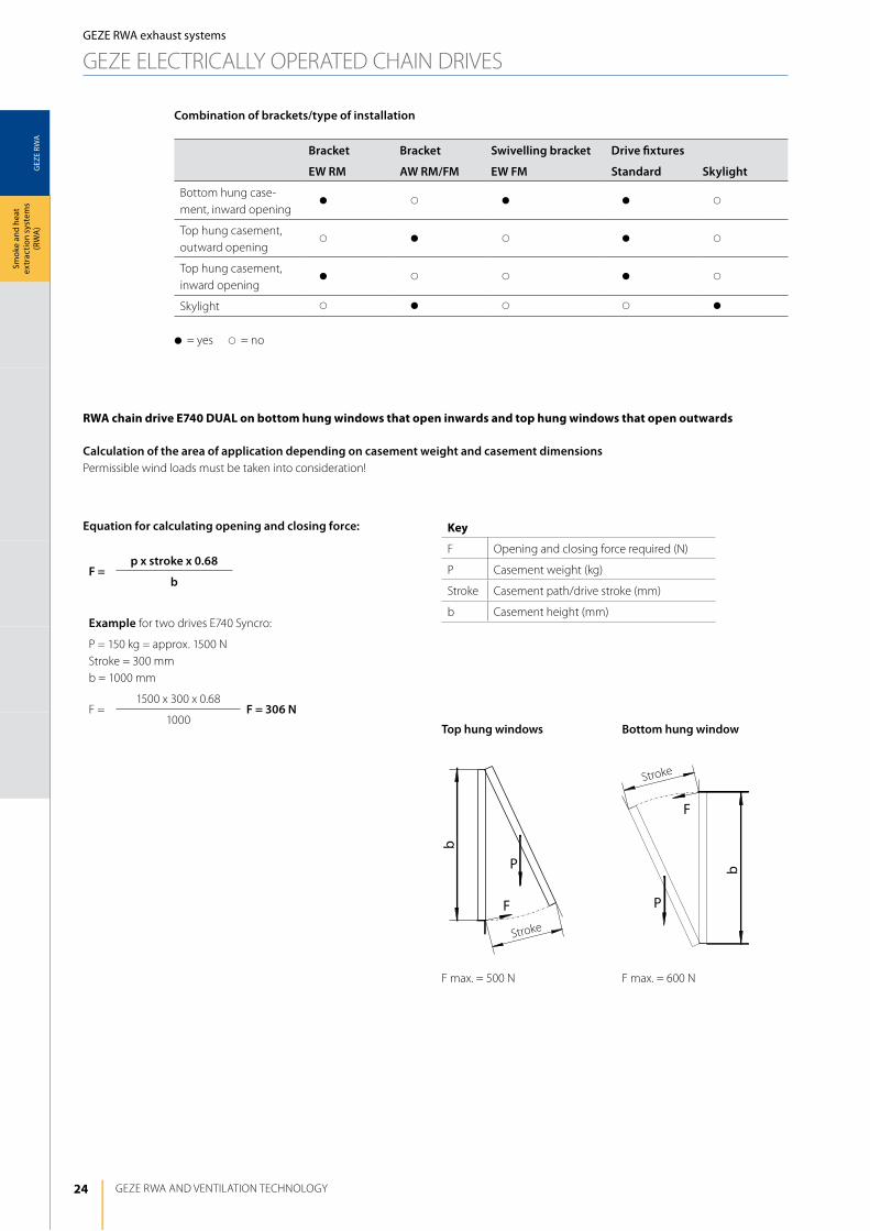
Bracket Bracket Swivelling bracket Drive fixtures
EW RM AW RM/FM EW FM Standard Skylight
Bottom hung case-ment, inward opening
d s d d s
Top hung casement, outward opening
s d s d s
Top hung casement, inward opening
d s s d s
Skylight s d s s d
d= yes s= no
Combination of brackets/type of installation
F =p x stroke x 0.68
b
Example for two drives E740 Syncro:
P = 150 kg = approx. 1500 NStroke = 300 mmb = 1000 mm
F =1500 x 300 x 0.68
F = 306 N1000
Top hung windows
F max. = 500 N
Bottom hung window
F max. = 600 N
Equation for calculating opening and closing force:
Stroke
Stroke
rwA chain drive e740 duAl on bottom hung windows that open inwards and top hung windows that open outwards
Calculation of the area of application depending on casement weight and casement dimensionsPermissible wind loads must be taken into consideration!
Key
F Opening and closing force required (N)
P Casement weight (kg)
Stroke Casement path/drive stroke (mm)
b Casement height (mm)
25
GEZ
E RW
A
b = (L1 – 42 mm)
L1
KK
25
22
22
22
22
25
6
36
21 21
6
36
3232
70
20
22
22
22
22
20
11 11
44 44
6 6
B = (L1 - 42 mm)
L1
K K
3535
36
GEZE RWA systems
Smok
e an
d he
at
extr
actio
n sy
stem
s (R
WA
)
GEZE RWA exhaust systems
GEZE ElECTRiCAlly OPERATEd ChAiN dRiVES
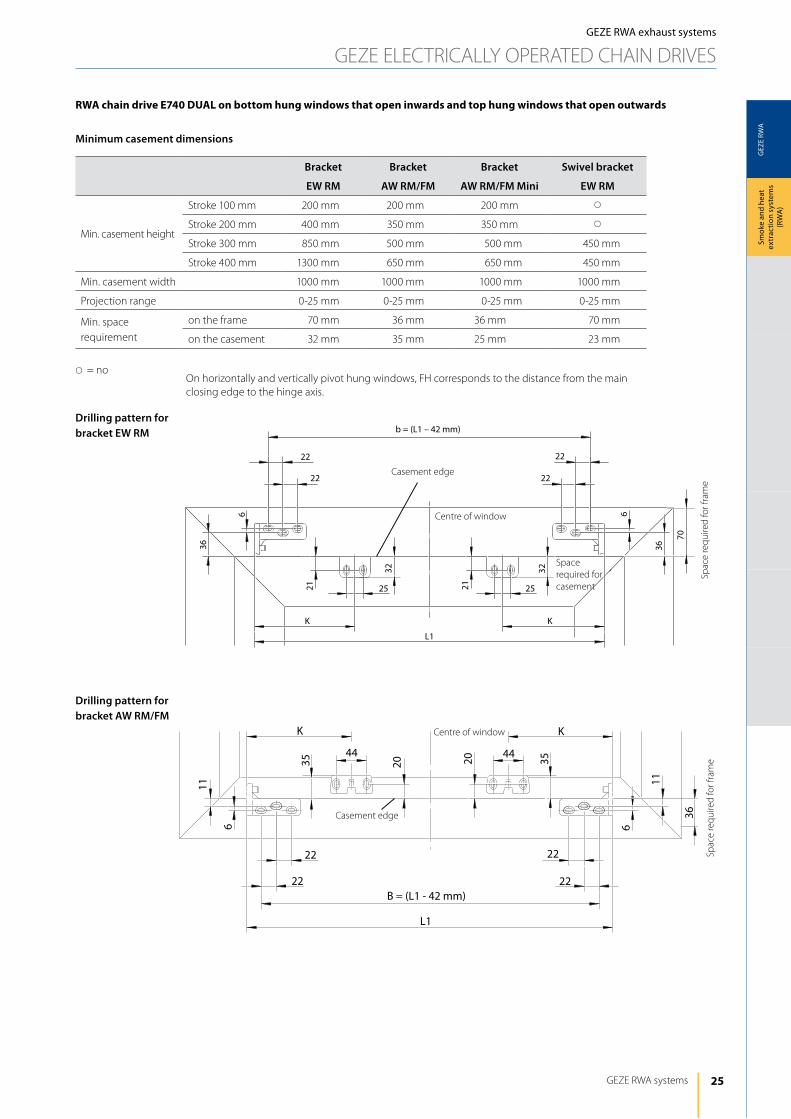
Drilling pattern for bracket EW RM
Drilling pattern for bracket AW RM/FM
Bracket Bracket Bracket Swivel bracket
EW RM AW RM/FM AW RM/FM Mini EW RM
Min. casement height
Stroke 100 mm 200 mm 200 mm 200 mm s
Stroke 200 mm 400 mm 350 mm 350 mm s
Stroke 300 mm 850 mm 500 mm 500 mm 450 mm
Stroke 400 mm 1300 mm 650 mm 650 mm 450 mm
Min. casement width 1000 mm 1000 mm 1000 mm 1000 mm
Projection range 0-25 mm 0-25 mm 0-25 mm 0-25 mm
Min. space requirement
on the frame 70 mm 36 mm 36 mm 70 mm
on the casement 32 mm 35 mm 25 mm 23 mm
s= no
Minimum casement dimensions
rwA chain drive e740 duAl on bottom hung windows that open inwards and top hung windows that open outwards
On horizontally and vertically pivot hung windows, Fh corresponds to the distance from the main closing edge to the hinge axis.
Spac
e re
quire
d fo
r fra
me
Spac
e re
quire
d fo
r fra
me
Casement edge
Casement edge
Centre of window
Centre of window
Space required for casement
26
GEZ
E RW
A
L1
6
11 11
6
22
22
22
22B (=L1 - 42mm)
12.5 25
36
KK
22222222
70
KK
28282828
23 36
L1
36
6
6
22
22 22
22
B (=L1 - 42mm)
GEZE RWA ANd VENTilATiON TEChNOlOGy
Smok
e an
d he
at
extr
actio
n sy
stem
s (R
WA
)GEZE RWA exhaust systems
GEZE ElECTRiCAlly OPERATEd ChAiN dRiVES
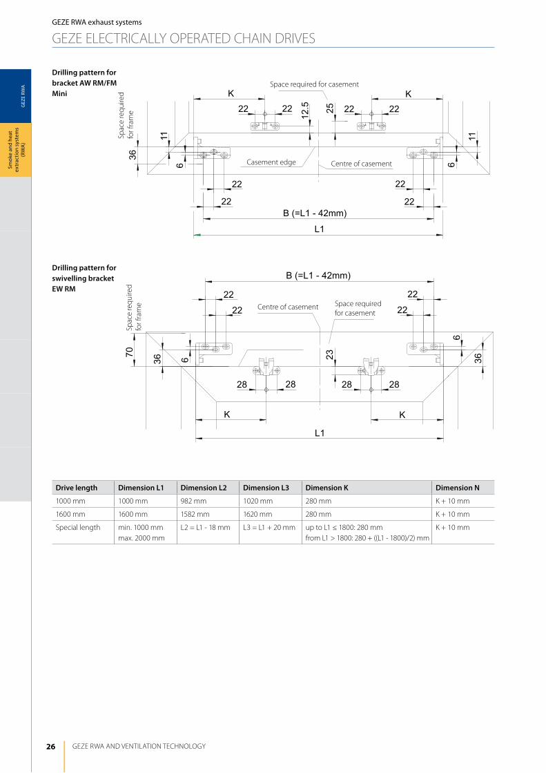
Drilling pattern for bracket AW RM/FM Mini
Drilling pattern for swivelling bracket EW RM
Drive length Dimension L1 Dimension L2 Dimension L3 Dimension K Dimension N
1000 mm 1000 mm 982 mm 1020 mm 280 mm K + 10 mm
1600 mm 1600 mm 1582 mm 1620 mm 280 mm K + 10 mm
Special length min. 1000 mmmax. 2000 mm
l2 = l1 - 18 mm l3 = l1 + 20 mm up to l1 ≤ 1800: 280 mmfrom l1 > 1800: 280 + ((l1 - 1800)/2) mm
K + 10 mm
Spac
e re
quire
d fo
r fra
me
Space required for casement
Space required for casement
Centre of casement
Centre of casement
Casement edge
Spac
e re
quire
d fo
r fra
me
27
GEZ
E RW
A
6,5
5525
,5
44
20
44 6,5
5525
,5
20
L3 = L1 + 20 mm
NN
PF
4060
GEZE RWA systems
Smok
e an
d he
at
extr
actio
n sy
stem
s (R
WA
)
GEZE RWA exhaust systems
GEZE ElECTRiCAlly OPERATEd ChAiN dRiVES
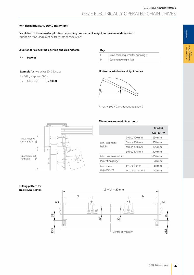
Drilling pattern for bracket AW RM/FM
Bracket
AW RM/FM
Min. casement height
Stroke 100 mm 250 mm
Stroke 200 mm 250 mm
Stroke 300 mm 325 mm
Stroke 400 mm 400 mm
Min. casement width 1000 mm
Projection range 0-20 mm
Min. space requirement
on the frame 68 mm
on the casement 42 mm
Minimum casement dimensions
F = P x 0.68
Equation for calculating opening and closing force:
rwA chain drive e740 duAl on skylight
Calculation of the area of application depending on casement weight and casement dimensionsPermissible wind loads must be taken into consideration!
Key
F drive force required for opening (N)
P Casement weight (kg)
Horizontal windows and light domes
F max. = 500 N (synchronous operation)
Example for two drives E740 Syncro:
P = 60 kg = approx. 600 N
F = 600 x 0.68 F = 408 N
Space required for casement
Space required for frame
Centre of window
28
GEZ
E RW
A
geze e820
GEZE RWA ANd VENTilATiON TEChNOlOGy
Smok
e an
d he
at
extr
actio
n sy
stem
s (R
WA
)GEZE RWA exhaust systems
GEZE ElECTRiCAlly OPERATEd ChAiN dRiVES
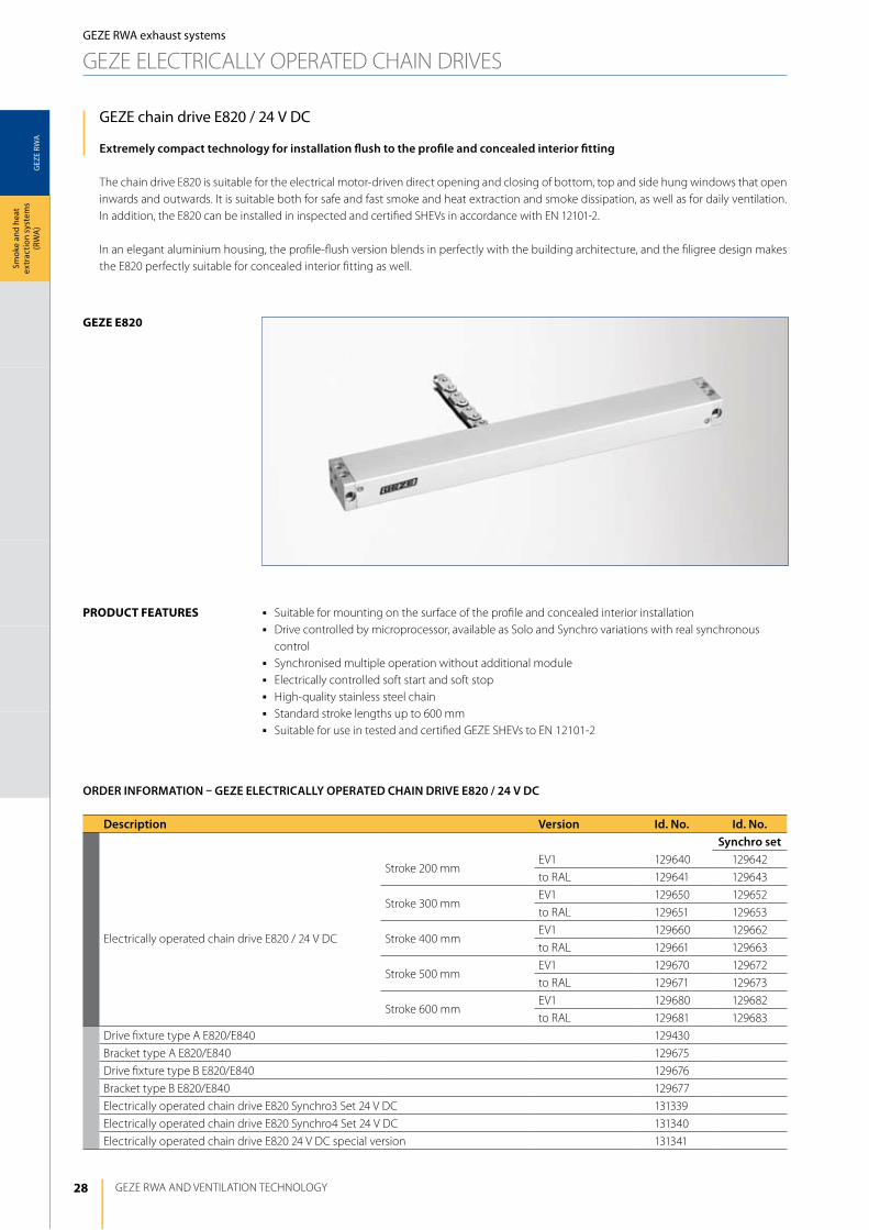
GEZE chain drive E820 / 24 V DC
Extremely compact technology for installation flush to the profile and concealed interior fitting
The chain drive E820 is suitable for the electrical motor-driven direct opening and closing of bottom, top and side hung windows that open inwards and outwards. it is suitable both for safe and fast smoke and heat extraction and smoke dissipation, as well as for daily ventilation. in addition, the E820 can be installed in inspected and certified ShEVs in accordance with EN 12101-2.
in an elegant aluminium housing, the profile-flush version blends in perfectly with the building architecture, and the filigree design makes the E820 perfectly suitable for concealed interior fitting as well.
j Suitable for mounting on the surface of the profile and concealed interior installationj drive controlled by microprocessor, available as Solo and Synchro variations with real synchronous
controlj Synchronised multiple operation without additional modulej Electrically controlled soft start and soft stopj high-quality stainless steel chainj Standard stroke lengths up to 600 mmj Suitable for use in tested and certified GEZE ShEVs to EN 12101-2
product FeAtureS
Description Version Id. No. Id. No. Synchro set
Electrically operated chain drive E820 / 24 V dC
Stroke 200 mmEV1 129640 129642
to RAl 129641 129643
Stroke 300 mmEV1 129650 129652
to RAl 129651 129653
Stroke 400 mmEV1 129660 129662
to RAl 129661 129663
Stroke 500 mmEV1 129670 129672
to RAl 129671 129673
Stroke 600 mmEV1 129680 129682
to RAl 129681 129683
drive fixture type A E820/E840 129430
Bracket type A E820/E840 129675
drive fixture type B E820/E840 129676
Bracket type B E820/E840 129677
Electrically operated chain drive E820 Synchro3 Set 24 V dC 131339
Electrically operated chain drive E820 Synchro4 Set 24 V dC 131340
Electrically operated chain drive E820 24 V dC special version 131341
ORDER INFORMATION – GEZE ELECTRICALLy OPERATED CHAIN DRIVE E820 / 24 V DC

29
GEZ
E RW
A
GEZE RWA systems
Smok
e an
d he
at
extr
actio
n sy
stem
s (R
WA
)
Accessories for GEZE electrically operated chain drives E820
GEZE drive fitting type A E820/E840for installation on frames and casements of bottom hung, top hung and side hung windows that open inwards and outwards
GEZE bracket type A E820/E840combined with drive fitting type A for installation on frames and casements of bottom hung, top hung and side hung windows that open inwards and outwards
GEZE drive fitting type B E820/E840for installation on the frame of bottom hung windows that open inwards
GEZE bracket type B E820/E840combined with drive fitting type B for frame installation on bottom hung windows that open inwardswithout drive fitting for frame installation on bottom hung and top hung windows that open inwards as well as on side hung windows that open outwards
Bracket type B E 820/E 840
drive fitting type B E 820/E 840
Bracket type A E 820/E 840
drive fitting type A E 820/E 840
GEZE RWA exhaust systems
GEZE ElECTRiCAlly OPERATEd ChAiN dRiVES
30
GEZ
E RW
A
145
26 13
41
12
L
LM
5
13
a
GEZE RWA ANd VENTilATiON TEChNOlOGy
Smok
e an
d he
at
extr
actio
n sy
stem
s (R
WA
)GEZE RWA exhaust systems
GEZE ElECTRiCAlly OPERATEd ChAiN dRiVES
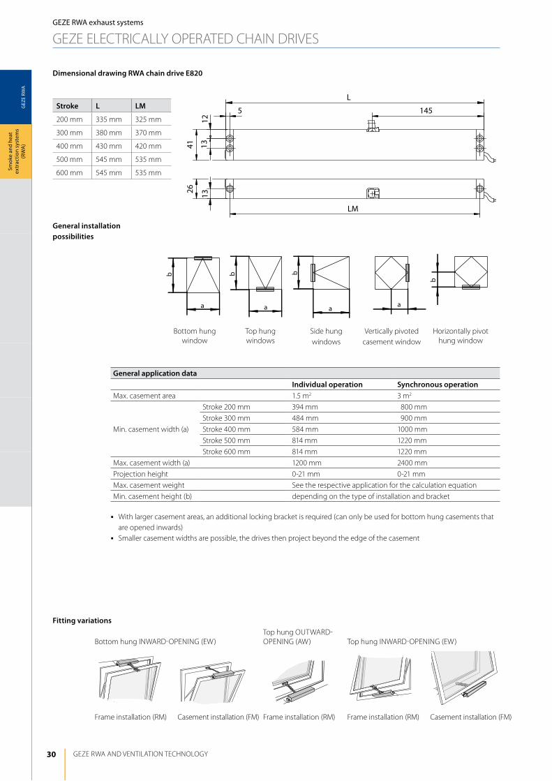
General installation possibilities
Fitting variations
General application dataIndividual operation Synchronous operation
Max. casement area 1.5 m2 3 m2
Min. casement width (a)
Stroke 200 mm 394 mm 1800 mm
Stroke 300 mm 484 mm 1900 mm
Stroke 400 mm 584 mm 1000 mm
Stroke 500 mm 814 mm 1220 mm
Stroke 600 mm 814 mm 1220 mm
Max. casement width (a) 1200 mm 2400 mm
Projection height 0-21 mm 0-21 mm
Max. casement weight See the respective application for the calculation equation
Min. casement height (b) depending on the type of installation and bracket
j With larger casement areas, an additional locking bracket is required (can only be used for bottom hung casements that are opened inwards)
j Smaller casement widths are possible, the drives then project beyond the edge of the casement
Dimensional drawing RWA chain drive E820
Bottom hung iNWARd-OPENiNG (EW)Top hung OUTWARd-OPENiNG (AW) Top hung iNWARd-OPENiNG (EW)
Frame installation (RM) Casement installation (FM) Frame installation (RM) Casement installation (FM)
Bottom hung window
Top hung windows
Side hung windows
Vertically pivoted casement window
horizontally pivot hung window
Frame installation (RM)
Stroke L LM
200 mm 335 mm 325 mm
300 mm 380 mm 370 mm
400 mm 430 mm 420 mm
500 mm 545 mm 535 mm
600 mm 545 mm 535 mm
31
GEZ
E RW
A
b
P
F
F
P
b
300 400
200
100150
250
050
200 500 600
100
200
GEZE RWA systems
Smok
e an
d he
at
extr
actio
n sy
stem
s (R
WA
)
GEZE RWA exhaust systems
GEZE ElECTRiCAlly OPERATEd ChAiN dRiVES
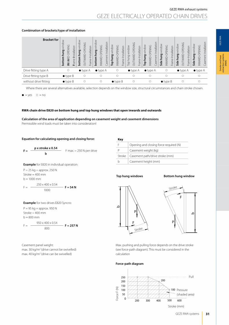
F =p x stroke x 0.54
b
Example for E820 in individual operation:
P = 25 kg = approx. 250 NStroke = 400 mmb = 1000 mm
F =250 x 400 x 0.54
F = 54 N1000
Example for two drives E820 Syncro:
P = 95 kg = approx. 950 NStroke = 400 mmb = 800 mm
F =950 x 400 x 0.54
F = 257 N800
Top hung windows
Casement panel weight: max. 30 kg/m2 (drive cannot be swivelled)max. 40 kg/m2 (drive can be swivelled)
Max. pushing and pulling force depends on the drive stroke (see force-path diagram). This must be considered in the calculation
Bottom hung window
Equation for calculating opening and closing force:
Stroke
Stroke
Bracket for
bott
om h
ung
win
dow
INW
ARd
-OPE
NiN
G
Fram
e-In
stal
latio
n
bott
om h
ung
win
dow
OU
TWAR
d-O
PEN
iNG
Fram
e-in
stal
latio
n
bott
om h
ung
win
dow
iNW
ARd
-OPE
NiN
G
Case
men
t ins
talla
tion
Top
hung
win
dow
iNW
ARd
-OPE
NiN
G
Fram
e-in
stal
latio
n
Top
hung
win
dow
OU
TWAR
d-O
PEN
iNG
Fram
e-in
stal
latio
n
Top
hung
win
dow
iNW
ARd
-OPE
NiN
G
Case
men
t ins
talla
tion
Side
hun
g w
indo
w
iNW
ARd
-OPE
NiN
G
Fram
e-in
stal
latio
n
Side
hun
g w
indo
w
OU
TWAR
d-O
PEN
iNG
Fram
e-in
stal
latio
n
Side
hun
g w
indo
w
iNW
ARd
-OPE
NiN
G
Case
men
t ins
talla
tion
drive fitting type A s dtype A dtype A s dtype A dtype A s dtype A dtype A
drive fitting type B dtype B s s s s s s s s
without drive fitting dtype B s s dtype B s s dtype B s s
Where there are several alternatives available, selection depends on the window size, structural circumstances and chain stroke chosen.
d= yes s= no
rwA chain drive e820 on bottom hung and top hung windows that open inwards and outwards
Calculation of the area of application depending on casement weight and casement dimensionsPermissible wind loads must be taken into consideration!
Combination of brackets/type of installation
Key
F Opening and closing force required (N)
P Casement weight (kg)
Stroke Casement path/drive stroke (mm)
b Casement height (mm)
F max. = 250 N per drive
Force-path diagram
Forc
e F
(N)
Stroke (mm)
Pressure(shaded area)
Pull
32
GEZ
E RW
A
39
55
31-x
x
x-7
A B
55
1012
22
5118
8
LA
LI
12 32 8 28
125
LI
140 LC
LB130
26
GEZE RWA ANd VENTilATiON TEChNOlOGy
Smok
e an
d he
at
extr
actio
n sy
stem
s (R
WA
)GEZE RWA exhaust systems
GEZE ElECTRiCAlly OPERATEd ChAiN dRiVES
Stroke(mm)
Bottom hungEW RM
Bottom hung/side hungEW RM
Side hungAW RM
Bottom hung/side hungEW FM
Bottom hung/side hungEW FM
Top hungEW RM
Top hungAW RM
Top hungAW RM
Top hungEW FM
Top hungEW FM
x = 16 mm x = 21 mm
Ü (mm) ≤10 ≤21 ≤10 ≤21 ≤10 ≤21 ≤10 ≤21 ≤10 ≤21 ≤10 ≤21 ≤10 ≤21 ≤10 ≤21 ≤10 ≤21 ≤10 ≤21
200 250 275 425 475 325 360 325 360 325 360 425 475 400 450 350 400 350 400 400 450
300 325 360 500 550 450 500 500 550 450 500 500 550 500 550 400 450 400 450 500 550
400 400 450 600 650 550 600 750 800 550 600 600 650 700 750 450 500 450 500 700 750
500 500 550 775 825 675 725 975 1025 675 725 700 750 800 850 600 650 600 650 800 850
600 600 650 950 1000 800 850 1200 1250 800 850 s s s s s s s s s s
d= yes s= no
B AC BA AD C B A
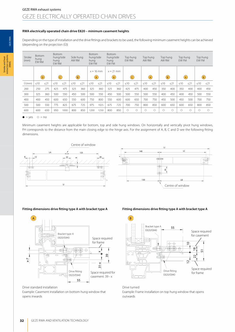
RWA electrically operated chain drive E820 – minimum casement heights
depending on the type of installation and the drive fittings and brackets to be used, the following minimum casement heights can be achieved (depending on the projection (Ü))
Minimum casement heights are applicable for bottom, top and side hung windows. On horizontally and vertically pivot hung windows, Fh corresponds to the distance from the main closing edge to the hinge axis. For the assignment of A, B, C and d see the following fitting dimensions.
drive standard installationExample: Casement installation on bottom hung window that opens inwards
drive turnedExample: Frame installation on top hung window that opens outwards
Fitting dimensions drive fitting type A with bracket type A Fitting dimensions drive fitting type A with bracket type A
Bracket type AE820/E840
drive fitting E820/E840
Bracket type AE820/E840
drive fitting E820/E840
Centre of window
Centre of window
Space required for casement
Space required for casement: 39 - x
Space required for frame
Space required for frame
33
GEZ
E RW
A
C
min
. 26
513
min
. 8
max
. 32
70
D
1011
40
A min
. 33
3
min
. 8
max
. 29
78
2727
LILI
8328 12
LA 125
2828
125LA
128 32
8
LI
LB130
26
140 LC13 13
LI
LB130
140 LC 1313
26
GEZE RWA systems
Smok
e an
d he
at
extr
actio
n sy
stem
s (R
WA
)
GEZE RWA exhaust systems
GEZE ElECTRiCAlly OPERATEd ChAiN dRiVES
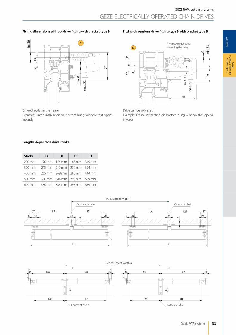
drive directly on the frameExample: Frame installation on bottom hung window that opens inwards
drive can be swivelledExample: Frame installation on bottom hung window that opens inwards
Fitting dimensions without drive fitting with bracket type B Fitting dimensions drive fitting type B with bracket type B
Stroke LA LB LC LI
200 mm 170 mm 174 mm 185 mm 349 mm
300 mm 215 mm 219 mm 230 mm 394 mm
400 mm 265 mm 269 mm 280 mm 444 mm
500 mm 380 mm 384 mm 395 mm 559 mm
600 mm 380 mm 384 mm 395 mm 559 mm
Lengths depend on drive stroke
A = space required for swivelling the drive
1/2 casement width a
1/2 casement width a
Centre of chain Centre of chain
Centre of chain Centre of chain
34
GEZ
E RW
A
geze e860
Parish hall heuchlingen, GermanyAlanus Academy of Art, Alfter, Germany
GEZE RWA ANd VENTilATiON TEChNOlOGy
Smok
e an
d he
at
extr
actio
n sy
stem
s (R
WA
)GEZE RWA exhaust systems
GEZE ElECTRiCAlly OPERATEd ChAiN dRiVES
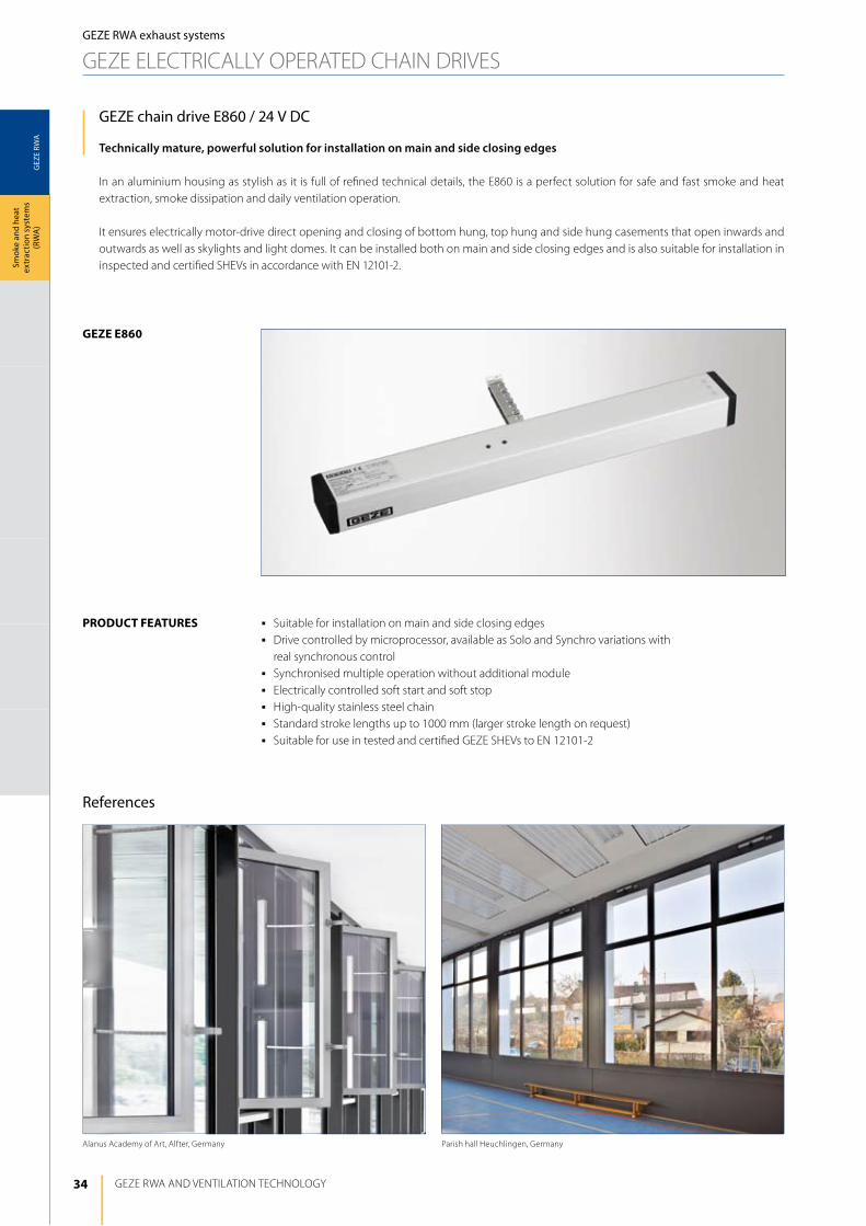
GEZE chain drive E860 / 24 V DC
Technically mature, powerful solution for installation on main and side closing edges
in an aluminium housing as stylish as it is full of refined technical details, the E860 is a perfect solution for safe and fast smoke and heat extraction, smoke dissipation and daily ventilation operation.
it ensures electrically motor-drive direct opening and closing of bottom hung, top hung and side hung casements that open inwards and outwards as well as skylights and light domes. it can be installed both on main and side closing edges and is also suitable for installation in inspected and certified ShEVs in accordance with EN 12101-2.
j Suitable for installation on main and side closing edgesj drive controlled by microprocessor, available as Solo and Synchro variations with
real synchronous controlj Synchronised multiple operation without additional modulej Electrically controlled soft start and soft stopj high-quality stainless steel chainj Standard stroke lengths up to 1000 mm (larger stroke length on request)j Suitable for use in tested and certified GEZE ShEVs to EN 12101-2
product FeAtureS
References
35
GEZ
E RW
A
GEZE RWA systems
Smok
e an
d he
at
extr
actio
n sy
stem
s (R
WA
)
GEZE RWA exhaust systems
GEZE ElECTRiCAlly OPERATEd ChAiN dRiVES
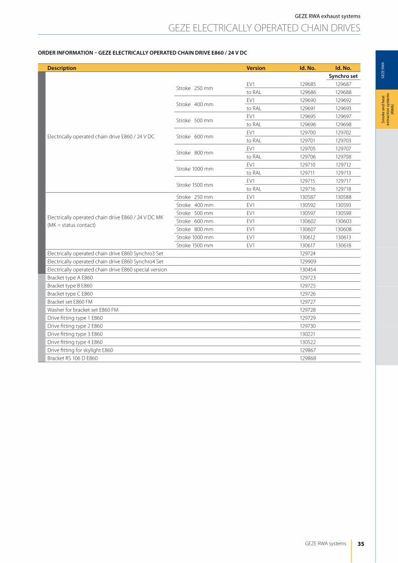
Description Version Id. No. Id. No. Synchro set
Electrically operated chain drive E860 / 24 V dC
Stroke 250 mmEV1 129685 129687
to RAl 129686 129688
Stroke 400 mmEV1 129690 129692
to RAl 129691 129693
Stroke 500 mmEV1 129695 129697
to RAl 129696 129698
Stroke 600 mmEV1 129700 129702
to RAl 129701 129703
Stroke 800 mmEV1 129705 129707
to RAl 129706 129708
Stroke 1000 mmEV1 129710 129712
to RAl 129711 129713
Stroke 1500 mmEV1 129715 129717
to RAl 129716 129718
Electrically operated chain drive E860 / 24 V dC MK(MK = status contact)
Stroke 250 mm EV1 130587 130588
Stroke 400 mm EV1 130592 130593
Stroke 500 mm EV1 130597 130598
Stroke 600 mm EV1 130602 130603
Stroke 800 mm EV1 130607 130608
Stroke 1000 mm EV1 130612 130613
Stroke 1500 mm EV1 130617 130618
Electrically operated chain drive E860 Synchro3 Set 129724
Electrically operated chain drive E860 Synchro4 Set 129909
Electrically operated chain drive E860 special version 130454
Bracket type A E860 129723
Bracket type B E860 129725
Bracket type C E860 129726
Bracket set E860 FM 129727
Washer for bracket set E860 FM 129728
drive fitting type 1 E860 129729
drive fitting type 2 E860 129730
drive fitting type 3 E860 130221
drive fitting type 4 E860 130522
drive fitting for skylight E860 129867
Bracket RS 106 d E860 129868
ORDER INFORMATION – GEZE ELECTRICALLy OPERATED CHAIN DRIVE E860 / 24 V DC
36
GEZ
E RW
A
GEZE RWA ANd VENTilATiON TEChNOlOGy
Smok
e an
d he
at
extr
actio
n sy
stem
s (R
WA
)
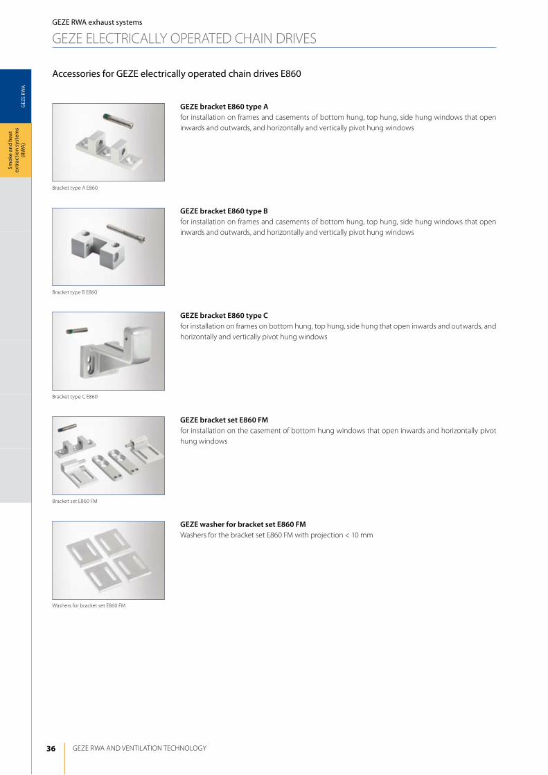
Accessories for GEZE electrically operated chain drives E860
GEZE bracket E860 type Afor installation on frames and casements of bottom hung, top hung, side hung windows that open inwards and outwards, and horizontally and vertically pivot hung windows
GEZE bracket E860 type Bfor installation on frames and casements of bottom hung, top hung, side hung windows that open inwards and outwards, and horizontally and vertically pivot hung windows
GEZE bracket E860 type Cfor installation on frames on bottom hung, top hung, side hung that open inwards and outwards, and horizontally and vertically pivot hung windows
GEZE bracket set E860 FMfor installation on the casement of bottom hung windows that open inwards and horizontally pivot hung windows
GEZE washer for bracket set E860 FMWashers for the bracket set E860 FM with projection < 10 mm
Washers for bracket set E860 FM
Bracket set E860 FM
Bracket type C E860
Bracket type B E860
Bracket type A E860
GEZE RWA exhaust systems
GEZE ElECTRiCAlly OPERATEd ChAiN dRiVES
37
GEZ
E RW
A
GEZE RWA systems
Smok
e an
d he
at
extr
actio
n sy
stem
s (R
WA
)
GEZE RWA exhaust systems
GEZE ElECTRiCAlly OPERATEd ChAiN dRiVES
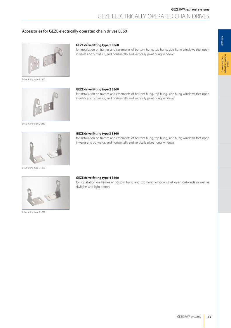
Accessories for GEZE electrically operated chain drives E860
GEZE drive fitting type 1 E860for installation on frames and casements of bottom hung, top hung, side hung windows that open inwards and outwards, and horizontally and vertically pivot hung windows
GEZE drive fitting type 2 E860for installation on frames and casements of bottom hung, top hung, side hung windows that open inwards and outwards, and horizontally and vertically pivot hung windows
GEZE drive fitting type 3 E860for installation on frames and casements of bottom hung, top hung, side hung windows that open inwards and outwards, and horizontally and vertically pivot hung windows
GEZE drive fitting type 4 E860for installation on frames of bottom hung and top hung windows that open outwards as well as skylights and light domes
drive fitting type 4 E860
drive fitting type 3 E860
drive fitting type 2 E860
drive fitting type 1 E860
38
GEZ
E RW
A
L
230
40
16
56
a
GEZE RWA ANd VENTilATiON TEChNOlOGy
Smok
e an
d he
at
extr
actio
n sy
stem
s (R
WA
)GEZE RWA exhaust systems
GEZE ElECTRiCAlly OPERATEd ChAiN dRiVES
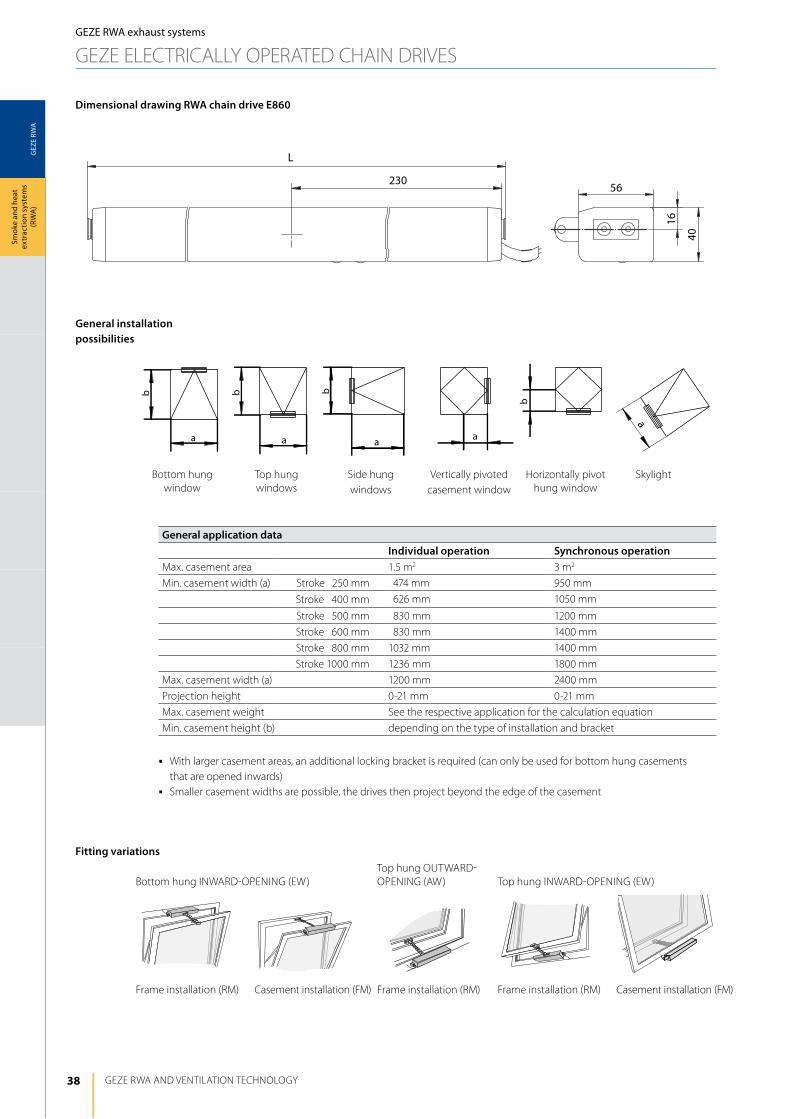
General installation possibilities
Fitting variations
General application dataIndividual operation Synchronous operation
Max. casement area 1.5 m2 3 m2
Min. casement width (a) Stroke 1250 mm 1474 mm 950 mm
Stroke 1400 mm 1626 mm 1050 mm
Stroke 1500 mm 1830 mm 1200 mm
Stroke 1600 mm 1830 mm 1400 mm
Stroke 1800 mm 1032 mm 1400 mm
Stroke 1000 mm 1236 mm 1800 mm
Max. casement width (a) 1200 mm 2400 mm
Projection height 0-21 mm 0-21 mm
Max. casement weight See the respective application for the calculation equation
Min. casement height (b) depending on the type of installation and bracket
j With larger casement areas, an additional locking bracket is required (can only be used for bottom hung casements that are opened inwards)j Smaller casement widths are possible, the drives then project beyond the edge of the casement
Dimensional drawing RWA chain drive E860
Bottom hung iNWARd-OPENiNG (EW)Top hung OUTWARd-OPENiNG (AW) Top hung iNWARd-OPENiNG (EW)
Frame installation (RM) Casement installation (FM) Frame installation (RM) Casement installation (FM)
Bottom hung window
Top hung windows
Side hung windows
Vertically pivoted casement window
horizontally pivot hung window
Skylight
Frame installation (RM)
39
GEZ
E RW
A
GEZE RWA systems
Smok
e an
d he
at
extr
actio
n sy
stem
s (R
WA
)
GEZE RWA exhaust systems
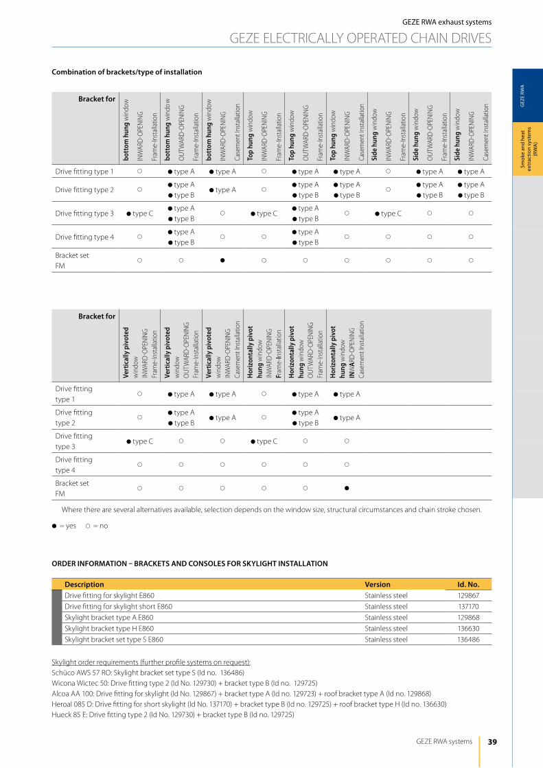
GEZE ElECTRiCAlly OPERATEd ChAiN dRiVES
Bracket for
bott
om h
ung
win
dow
iNW
ARd
-OPE
NiN
G
Fram
e-in
stal
latio
n
bott
om h
ung
win
dow
OU
TWAR
d-O
PEN
iNG
Fram
e-in
stal
latio
n
bott
om h
ung
win
dow
iNW
ARd
-OPE
NiN
G
Case
men
t ins
talla
tion
Top
hung
win
dow
iNW
ARd
-OPE
NiN
G
Fram
e-in
stal
latio
n
Top
hung
win
dow
OU
TWAR
d-O
PEN
iNG
Fram
e-in
stal
latio
n
Top
hung
win
dow
iNW
ARd
-OPE
NiN
G
Case
men
t ins
talla
tion
Side
hun
g w
indo
w
iNW
ARd
-OPE
NiN
G
Fram
e-in
stal
latio
n
Side
hun
g w
indo
w
OU
TWAR
d-O
PEN
iNG
Fram
e-in
stal
latio
n
Side
hun
g w
indo
w
iNW
ARd
-OPE
NiN
G
Case
men
t ins
talla
tion
drive fitting type 1 s dtype A dtype A s dtype A dtype A s dtype A dtype A
drive fitting type 2 sdtype Adtype B
dtype A sdtype Adtype B
dtype Adtype B
sdtype Adtype B
dtype Adtype B
drive fitting type 3 dtype Cdtype Adtype B
s dtype Cdtype Adtype B
s dtype C s s
drive fitting type 4 sdtype Adtype B
s sdtype Adtype B
s s s s
Bracket setFM
s s d s s s s s s
Bracket for
Vert
ical
ly p
ivot
ed
win
dow
iNW
ARd
-OPE
NiN
GFr
ame-
inst
alla
tion
Vert
ical
ly p
ivot
ed
win
dow
OU
TWAR
d-O
PEN
iNG
Fram
e-in
stal
latio
n
Vert
ical
ly p
ivot
ed
win
dow
iNW
ARd
-OPE
NiN
GCa
sem
ent i
nsta
llatio
n
Hor
izon
tally
piv
ot
hung
win
dow
iNW
ARd
-OPE
NiN
GFr
ame-
Inst
alla
tion
Hor
izon
tally
piv
ot
hung
win
dow
OU
TWAR
d-O
PEN
iNG
Fram
e-in
stal
latio
n
Hor
izon
tally
piv
ot
hung
win
dow
INW
ARd
-OPE
NiN
GCa
sem
ent i
nsta
llatio
n
drive fitting type 1
s dtype A dtype A s dtype A dtype A
drive fitting type 2
sdtype Adtype B
dtype A sdtype Adtype B
dtype A
drive fitting type 3
dtype C s s dtype C s s
drive fitting type 4
s s s s s s
Bracket setFM
s s s s s d
Where there are several alternatives available, selection depends on the window size, structural circumstances and chain stroke chosen.
d= yes s= no
Combination of brackets/type of installation
Description Version Id. No. drive fitting for skylight E860 Stainless steel 129867
drive fitting for skylight short E860 Stainless steel 137170
Skylight bracket type A E860 Stainless steel 129868
Skylight bracket type h E860 Stainless steel 136630
Skylight bracket set type S E860 Stainless steel 136486
Skylight order requirements (further profile systems on request):Schüco AWS 57 RO: Skylight bracket set type S (id no. 136486)Wicona Wictec 50: drive fitting type 2 (id No. 129730) + bracket type B (id no. 129725)Alcoa AA 100: drive fitting for skylight (id No. 129867) + bracket type A (id no. 129723) + roof bracket type A (id no. 129868)heroal 085 d: drive fitting for short skylight (id No. 137170) + bracket type B (id no. 129725) + roof bracket type h (id no. 136630) hueck 85 E: drive fitting type 2 (id No. 129730) + bracket type B (id no. 129725)
ORDER INFORMATION – BRACKETS AND CONSOLES FOR SKyLIGHT INSTALLATION
40
GEZ
E RW
A
bP
F
F
P
b
PF
0 0
15001000400 500 800600 700
600
400
200300
500
0100
600600
400300
600600
250
600 600
200
600
GEZE RWA ANd VENTilATiON TEChNOlOGy
Smok
e an
d he
at
extr
actio
n sy
stem
s (R
WA
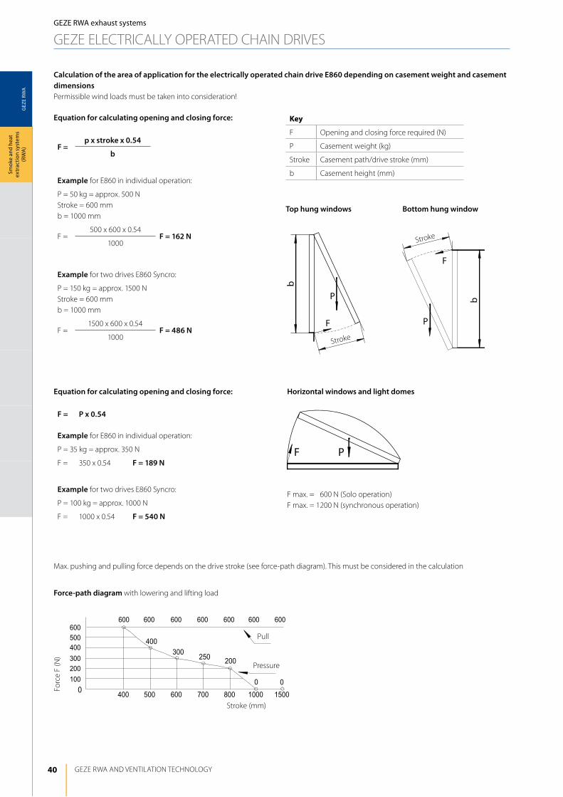
) F =p x stroke x 0.54
b
Example for E860 in individual operation:
P = 50 kg = approx. 500 NStroke = 600 mmb = 1000 mm
F =500 x 600 x 0.54
F = 162 N1000
Example for two drives E860 Syncro:
P = 150 kg = approx. 1500 NStroke = 600 mmb = 1000 mm
F =1500 x 600 x 0.54
F = 486 N1000
Top hung windows
Max. pushing and pulling force depends on the drive stroke (see force-path diagram). This must be considered in the calculation
Bottom hung window
Equation for calculating opening and closing force:
Stroke
Stroke
Calculation of the area of application for the electrically operated chain drive E860 depending on casement weight and casement dimensionsPermissible wind loads must be taken into consideration!
Key
F Opening and closing force required (N)
P Casement weight (kg)
Stroke Casement path/drive stroke (mm)
b Casement height (mm)
Force-path diagram with lowering and lifting load
Forc
e F
(N)
Stroke (mm)
Pressure
Pull
F = P x 0.54
Equation for calculating opening and closing force: Horizontal windows and light domes
F max. = 1600 N (Solo operation)F max. = 1200 N (synchronous operation)
Example for E860 in individual operation:
P = 35 kg = approx. 350 N
F = 350 x 0.54 F = 189 N
Example for two drives E860 Syncro:
P = 100 kg = approx. 1000 N
F = 1000 x 0.54 F = 540 N
GEZE RWA exhaust systems
GEZE ElECTRiCAlly OPERATEd ChAiN dRiVES
41
GEZ
E RW
A
min
. 30
(67)
13
14
15
5116
80
43
24
LE10 22
42
55
198
42
22 10
11
A
3730
(x–1
6)
(88)
2213
7216
80
4324
LE10 22
42
55
198
42
22 10
B
11
x37
GEZE RWA systems
Smok
e an
d he
at
extr
actio
n sy
stem
s (R
WA
)
GEZE RWA exhaust systems
GEZE ElECTRiCAlly OPERATEd ChAiN dRiVES
drive fitting type 1 drive fitting type 2
dimension x =
35 mm
drive fitting type 2
dimension x =
51 mm
drive fitting type 3
+ bracket type C
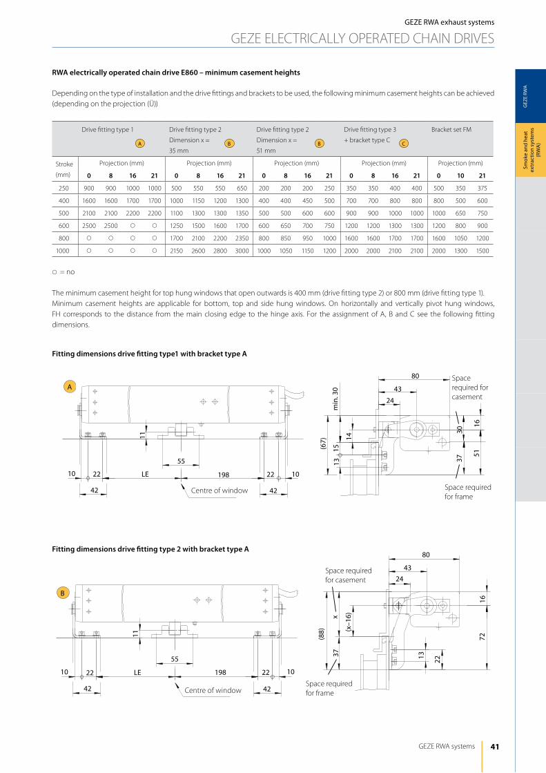
Bracket set FM
Stroke
(mm)
Projection (mm) Projection (mm) Projection (mm) Projection (mm) Projection (mm)
0 8 16 21 0 8 16 21 0 8 16 21 0 8 16 21 0 10 21
1250 900 900 1000 1000 500 550 550 650 200 200 200 250 350 350 400 400 500 350 375
1400 1600 1600 1700 1700 1000 1150 1200 1300 400 400 450 500 700 700 800 800 800 500 600
1500 2100 2100 2200 2200 1100 1300 1300 1350 500 500 600 600 900 900 1000 1000 1000 650 750
1600 2500 2500 s s 1250 1500 1600 1700 600 650 700 750 1200 1200 1300 1300 1200 800 900
1800 s s s s 1700 2100 2200 2350 800 850 950 1000 1600 1600 1700 1700 1600 1050 1200
1000 s s s s 2150 2600 2800 3000 1000 1050 1150 1200 2000 2000 2100 2100 2000 1300 1500
s= no
The minimum casement height for top hung windows that open outwards is 400 mm (drive fitting type 2) or 800 mm (drive fitting type 1).Minimum casement heights are applicable for bottom, top and side hung windows. On horizontally and vertically pivot hung windows, Fh corresponds to the distance from the main closing edge to the hinge axis. For the assignment of A, B and C see the following fitting dimensions.
B CBA
RWA electrically operated chain drive E860 – minimum casement heights
depending on the type of installation and the drive fittings and brackets to be used, the following minimum casement heights can be achieved (depending on the projection (Ü))
Fitting dimensions drive fitting type1 with bracket type A
Fitting dimensions drive fitting type 2 with bracket type A
Centre of window
Centre of window
Space required for casement
Space required for frame
Space required for casement
Space required for frame
42
GEZ
E RW
A
10 22
42
34
LE 198 22 10
42
107
6124
16
(90)
74
1320
45
28
C
4655
A80
43
2441
24
(65)
101055
11
198
42
22 LE
42
22
44.5
3
44,5
22
35
LE 206,522
25
1312
10 74
44,5
3 28
GEZE RWA ANd VENTilATiON TEChNOlOGy
Smok
e an
d he
at
extr
actio
n sy
stem
s (R
WA
)GEZE RWA exhaust systems
GEZE ElECTRiCAlly OPERATEd ChAiN dRiVES
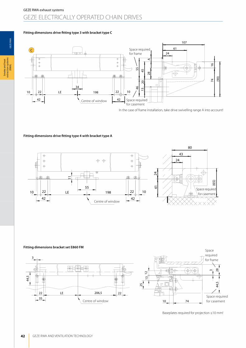
Fitting dimensions drive fitting type 3 with bracket type C
Fitting dimensions drive fitting type 4 with bracket type A
Fitting dimensions bracket set E860 FM
Centre of window
Centre of window
Centre of window
in the case of frame installation, take drive swivelling range A into account!
Baseplates required for projection ≤10 mm!
Space required for frame
Space required for casement
Space required for casement
Space required for casement
Space required for frame
43
GEZ
E RW
A
1 2
GEZE RWA systems
Smok
e an
d he
at
extr
actio
n sy
stem
s (R
WA
)
GEZE RWA exhaust systems
GEZE ElECTRiCAlly OPERATEd ChAiN dRiVES
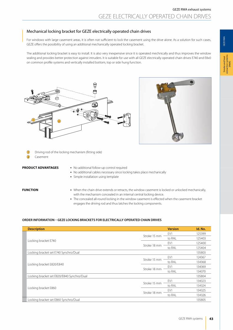
Mechanical locking bracket for GEZE electrically operated chain drives
For windows with large casement areas, it is often not sufficient to lock the casement using the drive alone. As a solution for such cases, GEZE offers the possibility of using an additional mechanically operated locking bracket.
The additional locking bracket is easy to install. it is also very inexpensive since it is operated mechnically and thus improves the window sealing and provides better protection against intruders. it is suitable for use with all GEZE electrically operated chain drives E740 and E8x0 on common profile systems and vertically installed bottom, top or side hung function.
driving rod of the locking mechanism (fitting side)
Casement
1
2
j No additional follow-up control requiredj No additional cables necessary since locking takes place mechanicallyj Simple installation using template
j When the chain drive extends or retracts, the window casement is locked or unlocked mechanically, with the mechanism concealed in an internal central locking device.
j The concealed all-round locking in the window casement is effected when the casement bracket engages the driving rod and thus latches the locking components.
product AdVAntAgeS
Function
Description Version Id. No.
locking bracket E740
Stroke 15 mmEV1 125399
to RAl 125403
Stroke 18 mmEV1 125400
to RAl 125404
locking bracket set E740 Synchro/dual 135803
locking bracket E820/E840
Stroke 15 mmEV1 124367
to RAl 134368
Stroke 18 mmEV1 134369
to RAl 134370
locking bracket set E820/E840 Synchro/dual 135804
locking bracket E860
Stroke 15 mmEV1 134323
to RAl 134324
Stroke 18 mmEV1 134325
to RAl 134326
locking bracket set E860 Synchro/dual 135805
ORDER INFORMATION – GEZE LOCKING BRACKETS FOR ELECTRICALLy OPERATED CHAIN DRIVES
44
GEZ
E RW
A
15/18
53
min
. 0,2
5+0
,5
1
5+0,5
42,5
min
. 0,2
1
36
255
min
. 0,2
+0,5
1
36
GEZE RWA ANd VENTilATiON TEChNOlOGy
Smok
e an
d he
at
extr
actio
n sy
stem
s (R
WA
)GEZE RWA exhaust systems
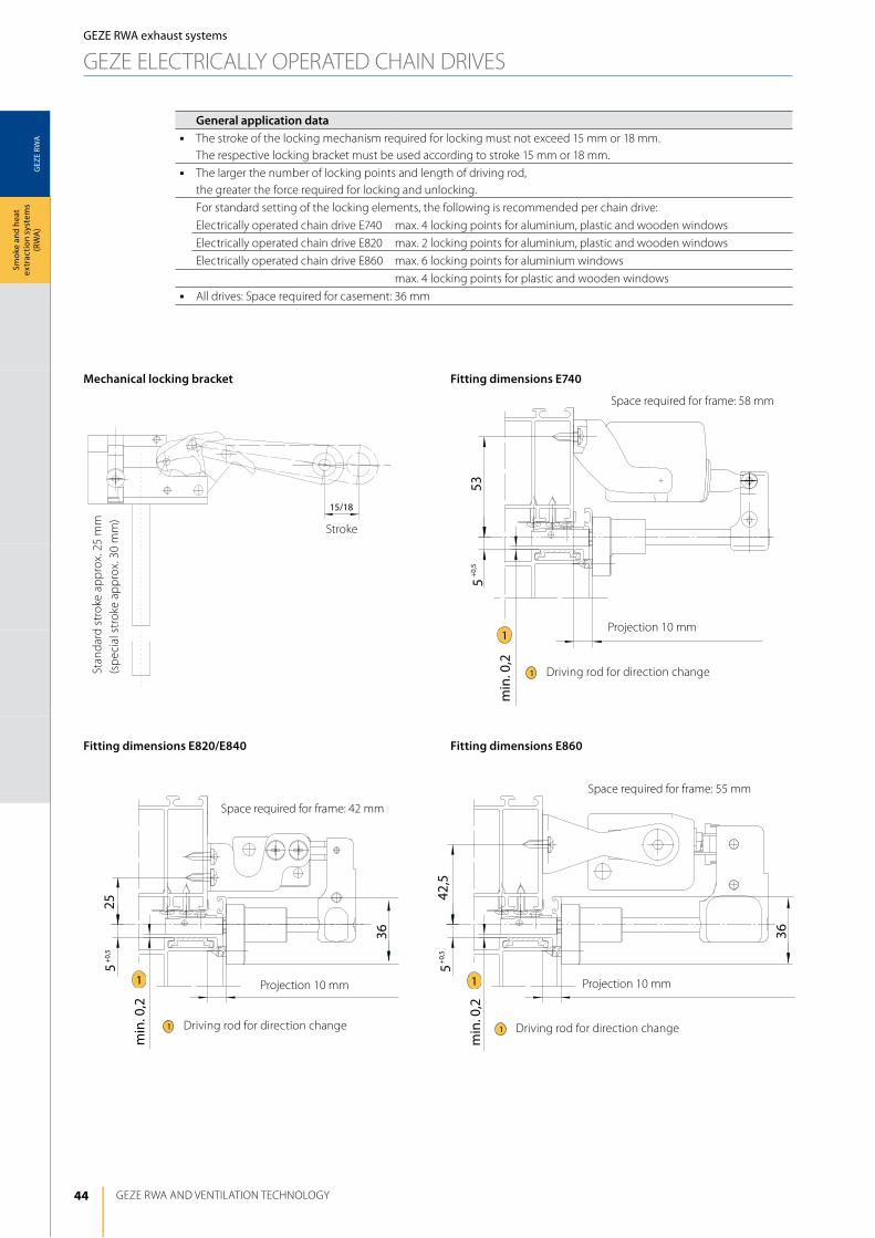
GEZE ElECTRiCAlly OPERATEd ChAiN dRiVESSt
anda
rd s
trok
e ap
prox
. 25
mm
(sp
ecia
l str
oke
appr
ox. 3
0 m
m)
Stroke
Mechanical locking bracket Fitting dimensions E740
Fitting dimensions E860Fitting dimensions E820/E840
Projection 10 mm
Projection 10 mmProjection 10 mm
driving rod for direction change1
driving rod for direction change1driving rod for direction change1
General application dataj The stroke of the locking mechanism required for locking must not exceed 15 mm or 18 mm.
The respective locking bracket must be used according to stroke 15 mm or 18 mm.j The larger the number of locking points and length of driving rod,
the greater the force required for locking and unlocking.
For standard setting of the locking elements, the following is recommended per chain drive:
Electrically operated chain drive E740 max. 4 locking points for aluminium, plastic and wooden windows
Electrically operated chain drive E820 max. 2 locking points for aluminium, plastic and wooden windows
Electrically operated chain drive E860 max. 6 locking points for aluminium windows
max. 4 locking points for plastic and wooden windowsj All drives: Space required for casement: 36 mm
Space required for frame: 58 mm
Space required for frame: 42 mm
Space required for frame: 55 mm
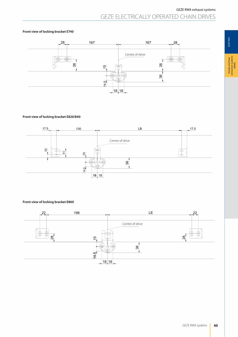
45
GEZ
E RW
A
1818
14.5
15
28 167 167 28
3838
36
130 LB17.5 17.5
1514.5
10
11
18 18
36
28
2222 LE198
28
1818
14.5
15
36
GEZE RWA systems
Smok
e an
d he
at
extr
actio
n sy
stem
s (R
WA
)
GEZE RWA exhaust systems
GEZE ElECTRiCAlly OPERATEd ChAiN dRiVES
Centre of drive
Centre of drive
Centre of drive
Front view of locking bracket E740
Front view of locking bracket E820/840
Front view of locking bracket E860
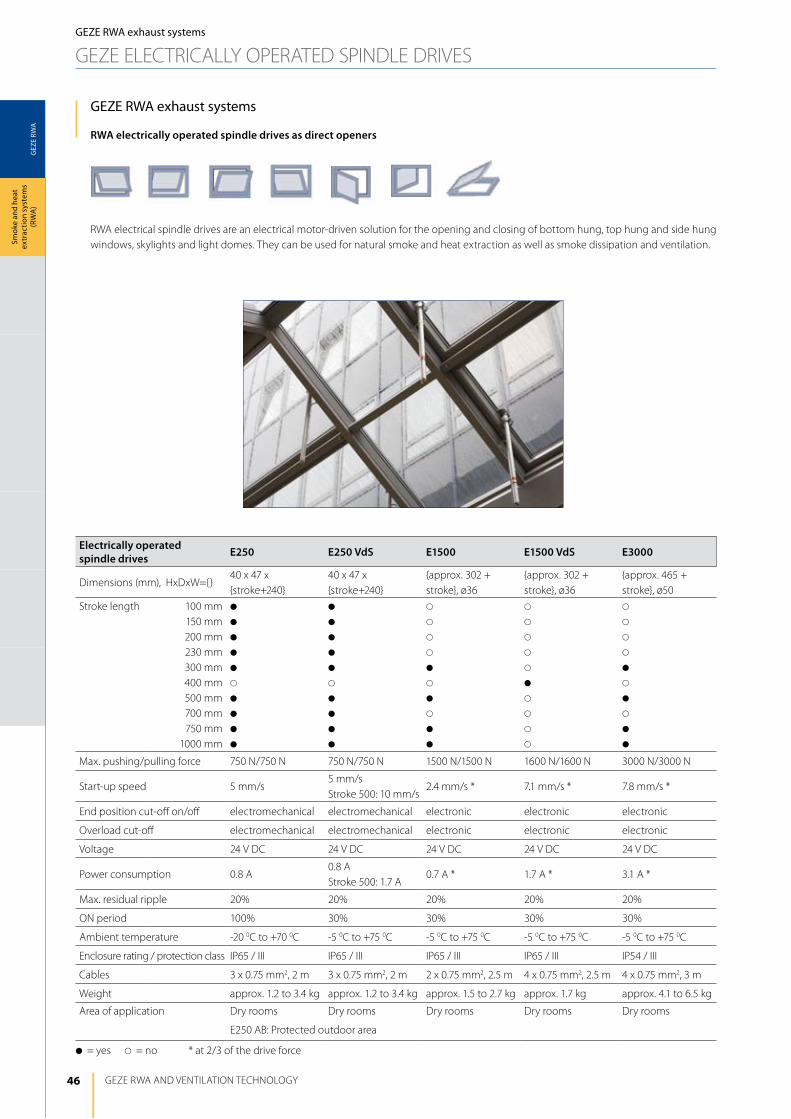
46
GEZ
E RW
A
GEZE RWA ANd VENTilATiON TEChNOlOGy
Smok
e an
d he
at
extr
actio
n sy
stem
s (R
WA
)GEZE RWA exhaust systems
GEZE ElECTRiCAlly OPERATEd SPiNdlE dRiVES
GEZE RWA exhaust systems
RWA electrically operated spindle drives as direct openers
RWA electrical spindle drives are an electrical motor-driven solution for the opening and closing of bottom hung, top hung and side hung windows, skylights and light domes. They can be used for natural smoke and heat extraction as well as smoke dissipation and ventilation.
Electrically operated spindle drives E250 E250 VdS E1500 E1500 VdS E3000
dimensions (mm), hxdxW={}40 x 47 x {stroke+240}
40 x 47 x {stroke+240}
{approx. 302 + stroke}, ø36
{approx. 302 + stroke}, ø36
{approx. 465 + stroke}, ø50
Stroke length 100 mm150 mm200 mm230 mm300 mm400 mm500 mm700 mm750 mm
1000 mm
d
d
d
d
d
s
d
d
d
d
d
d
d
d
d
s
d
d
d
d
s
s
s
s
d
s
d
s
d
d
s
s
s
s
s
d
s
s
s
s
s
s
s
s
d
s
d
s
d
d
Max. pushing/pulling force 750 N/750 N 750 N/750 N 1500 N/1500 N 1600 N/1600 N 3000 N/3000 N
Start-up speed 5 mm/s5 mm/sStroke 500: 10 mm/s
2.4 mm/s * 7.1 mm/s * 7.8 mm/s *
End position cut-off on/off electromechanical electromechanical electronic electronic electronic
Overload cut-off electromechanical electromechanical electronic electronic electronic
Voltage 24 V dC 24 V dC 24 V dC 24 V dC 24 V dC
Power consumption 0.8 A0.8 AStroke 500: 1.7 A
0.7 A * 1.7 A * 3.1 A *
Max. residual ripple 20% 20% 20% 20% 20%
ON period 100% 30% 30% 30% 30%
Ambient temperature -20 0C to +70 0C -5 0C to +75 0C -5 0C to +75 0C -5 0C to +75 0C -5 0C to +75 0C
Enclosure rating / protection class iP65 / iii iP65 / iii iP65 / iii iP65 / iii iP54 / iii
Cables 3 x 0.75 mm2, 2 m 3 x 0.75 mm2, 2 m 2 x 0.75 mm2, 2.5 m 4 x 0.75 mm2, 2.5 m 4 x 0.75 mm2, 3 m
Weight approx. 1.2 to 3.4 kg approx. 1.2 to 3.4 kg approx. 1.5 to 2.7 kg approx. 1.7 kg approx. 4.1 to 6.5 kg
Area of application dry rooms dry rooms dry rooms dry rooms dry rooms
E250 AB: Protected outdoor area
d= yes s= no * at 2/3 of the drive force
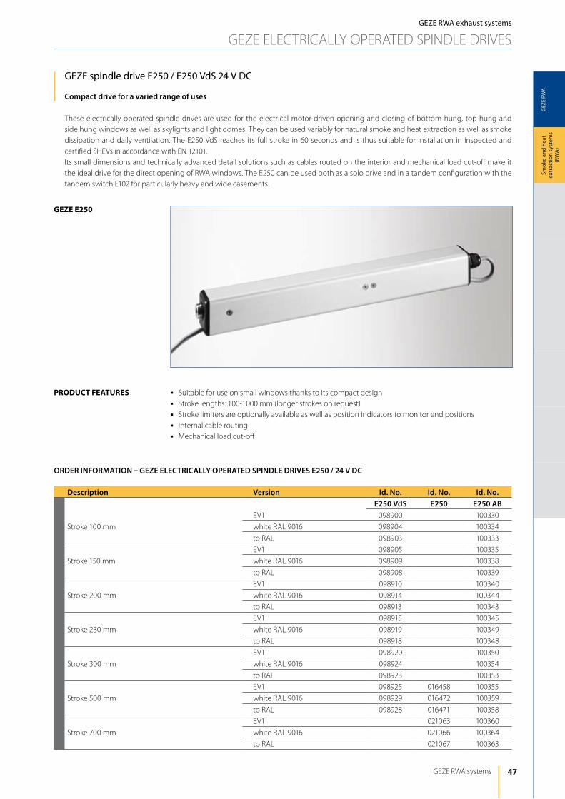
47
GEZ
E RW
A
geze e250
GEZE RWA systems
Smok
e an
d he
at
extr
actio
n sy
stem
s (R
WA
)
GEZE spindle drive E250 / E250 VdS 24 V DC
Compact drive for a varied range of uses
These electrically operated spindle drives are used for the electrical motor-driven opening and closing of bottom hung, top hung and side hung windows as well as skylights and light domes. They can be used variably for natural smoke and heat extraction as well as smoke dissipation and daily ventilation. The E250 VdS reaches its full stroke in 60 seconds and is thus suitable for installation in inspected and certified ShEVs in accordance with EN 12101.its small dimensions and technically advanced detail solutions such as cables routed on the interior and mechanical load cut-off make it the ideal drive for the direct opening of RWA windows. The E250 can be used both as a solo drive and in a tandem configuration with the tandem switch E102 for particularly heavy and wide casements.
j Suitable for use on small windows thanks to its compact designj Stroke lengths: 100-1000 mm (longer strokes on request)j Stroke limiters are optionally available as well as position indicators to monitor end positionsj internal cable routingj Mechanical load cut-off
product FeAtureS
Description Version Id. No. Id. No. Id. No.E250 VdS E250 E250 AB
Stroke 100 mm
EV1 098900 100330
white RAl 9016 098904 100334
to RAl 098903 100333
Stroke 150 mm
EV1 098905 100335
white RAl 9016 098909 100338
to RAl 098908 100339
Stroke 200 mm
EV1 098910 100340
white RAl 9016 098914 100344
to RAl 098913 100343
Stroke 230 mm
EV1 098915 100345
white RAl 9016 098919 100349
to RAl 098918 100348
Stroke 300 mm
EV1 098920 100350
white RAl 9016 098924 100354
to RAl 098923 100353
Stroke 500 mm
EV1 098925 016458 100355
white RAl 9016 098929 016472 100359
to RAl 098928 016471 100358
Stroke 700 mm
EV1 021063 100360
white RAl 9016 021066 100364
to RAl 021067 100363
ORDER INFORMATION – GEZE ELECTRICALLy OPERATED SPINDLE DRIVES E250 / 24 V DC
GEZE RWA exhaust systems
GEZE ElECTRiCAlly OPERATEd SPiNdlE dRiVES
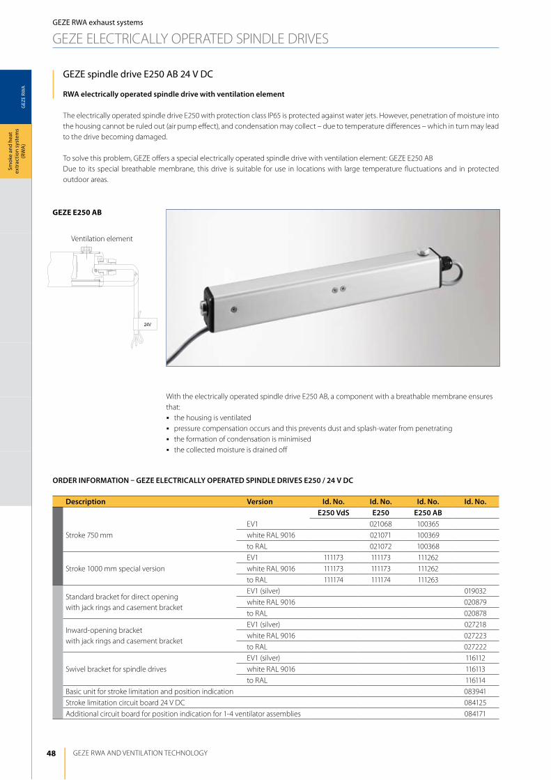
48
GEZ
E RW
A
geze e250 AB
24V
GEZE RWA ANd VENTilATiON TEChNOlOGy
Smok
e an
d he
at
extr
actio
n sy
stem
s (R
WA
)
GEZE spindle drive E250 AB 24 V DC
RWA electrically operated spindle drive with ventilation element
The electrically operated spindle drive E250 with protection class iP65 is protected against water jets. however, penetration of moisture into the housing cannot be ruled out (air pump effect), and condensation may collect – due to temperature differences – which in turn may lead to the drive becoming damaged.
To solve this problem, GEZE offers a special electrically operated spindle drive with ventilation element: GEZE E250 ABdue to its special breathable membrane, this drive is suitable for use in locations with large temperature fluctuations and in protected outdoor areas.
Description Version Id. No. Id. No. Id. No. Id. No.E250 VdS E250 E250 AB
Stroke 750 mm
EV1 021068 100365
white RAl 9016 021071 100369
to RAl 021072 100368
Stroke 1000 mm special version
EV1 111173 111173 111262
white RAl 9016 111173 111173 111262
to RAl 111174 111174 111263
Standard bracket for direct opening with jack rings and casement bracket
EV1 (silver) 019032
white RAl 9016 020879
to RAl 020878
inward-opening bracket with jack rings and casement bracket
EV1 (silver) 027218
white RAl 9016 027223
to RAl 027222
Swivel bracket for spindle drives
EV1 (silver) 116112
white RAl 9016 116113
to RAl 116114
Basic unit for stroke limitation and position indication 083941
Stroke limitation circuit board 24 V dC 084125
Additional circuit board for position indication for 1-4 ventilator assemblies 084171
ORDER INFORMATION – GEZE ELECTRICALLy OPERATED SPINDLE DRIVES E250 / 24 V DC
GEZE RWA exhaust systems
GEZE ElECTRiCAlly OPERATEd SPiNdlE dRiVES
With the electrically operated spindle drive E250 AB, a component with a breathable membrane ensures that:j the housing is ventilatedj pressure compensation occurs and this prevents dust and splash-water from penetratingj the formation of condensation is minimisedj the collected moisture is drained off
Ventilation element

49
GEZ
E RW
A
GEZE RWA systems
Smok
e an
d he
at
extr
actio
n sy
stem
s (R
WA
)
Accessories for GEZE electrically operated drives E250 / E250 VdS / E250 AB
GEZE standard bracketfor direct opening of the E250Scope of supply with jack rings and casement bracket
GEZE inward-opening bracketfor direct opening of the E250 on windows that open inwardsScope of supply with jack rings and casement bracket
GEZE swivel bracketfor direct opening of the E250Scope of supply with jack rings, casement bracket and countersunk screws
With the swivel bracket the spindle drive E250 can be fitted in a tandem version directly to the side closing edge. This results in a greater opening width compared with a fitting with comparable stroke length at the main closing edge of the skylight.
GEZE basic unit for stroke limitation (and position indication)Scope of supply with reed switch, cable tie and cable run(drawing no. 45130-9-0990)
GEZE stroke limitation circuit boardFor limiting the stroke, a basic unit should be fitted in addition to the stroke limitation circuit board (see drawing no. 45130-9-0990)
GEZE additional circuit board for position indication for 1-4 ventilator assembliesFor position indication, one or two basic units (depending on the application) should be fitted in addition to the position indication circuit board (see drawing no. 45130-9-0990)
GEZE RWA exhaust systems
GEZE ElECTRiCAlly OPERATEd SPiNdlE dRiVES
Additional circuit board for position indication
Stroke limitation circuit board
Basic unit for stroke limitation
Swivel bracket
inward-opening bracket
Standard bracket
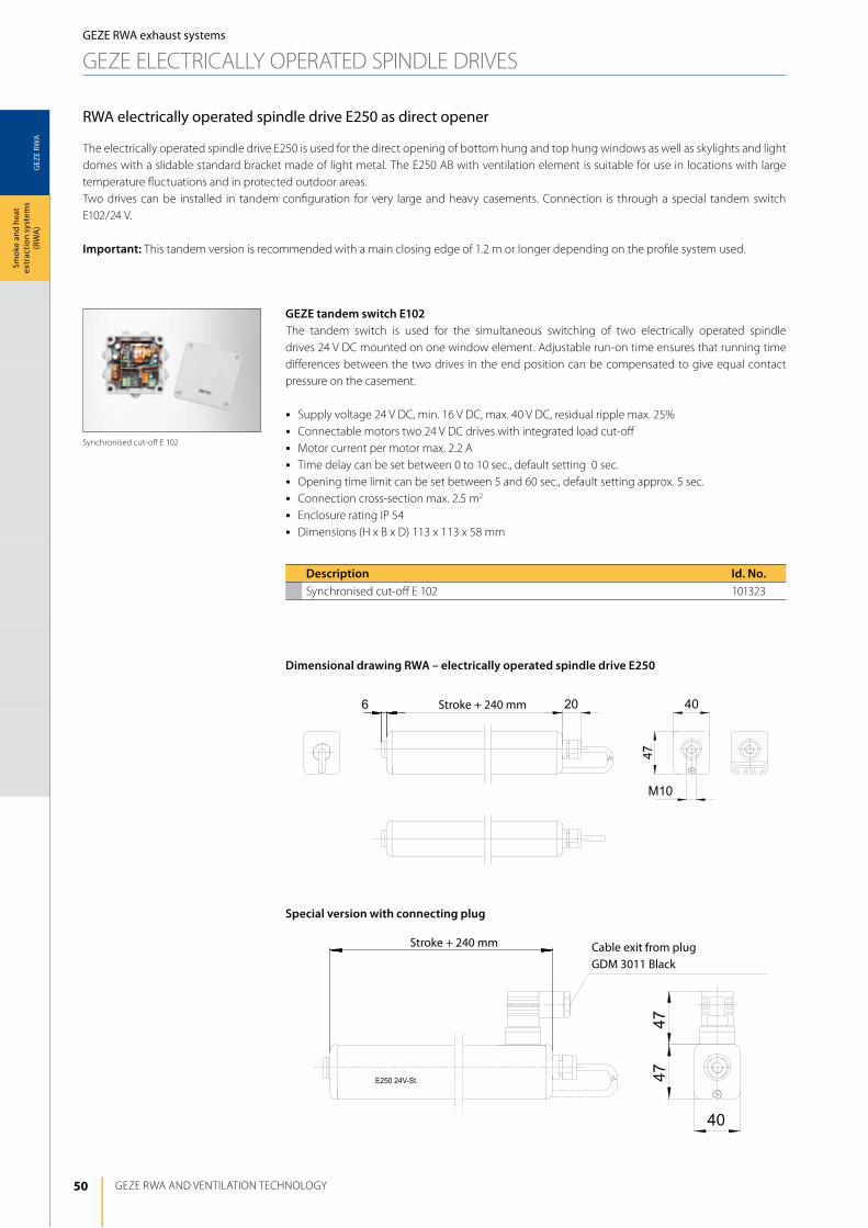
50
GEZ
E RW
A
6 20 40
47
M10
E250 24V-St.
40
4747
GEZE RWA ANd VENTilATiON TEChNOlOGy
Smok
e an
d he
at
extr
actio
n sy
stem
s (R
WA
)
RWA electrically operated spindle drive E250 as direct opener
GEZE RWA exhaust systems
GEZE ElECTRiCAlly OPERATEd SPiNdlE dRiVES
Cable exit from plug GDM 3011 Black
Stroke + 240 mm
Dimensional drawing RWA – electrically operated spindle drive E250
Special version with connecting plug
The electrically operated spindle drive E250 is used for the direct opening of bottom hung and top hung windows as well as skylights and light domes with a slidable standard bracket made of light metal. The E250 AB with ventilation element is suitable for use in locations with large temperature fluctuations and in protected outdoor areas.Two drives can be installed in tandem configuration for very large and heavy casements. Connection is through a special tandem switch E102/24 V.
Important: This tandem version is recommended with a main closing edge of 1.2 m or longer depending on the profile system used.
GEZE tandem switch E102The tandem switch is used for the simultaneous switching of two electrically operated spindle drives 24 V dC mounted on one window element. Adjustable run-on time ensures that running time differences between the two drives in the end position can be compensated to give equal contact pressure on the casement.
j Supply voltage 24 V dC, min. 16 V dC, max. 40 V dC, residual ripple max. 25%j Connectable motors two 24 V dC drives with integrated load cut-offj Motor current per motor max. 2.2 Aj Time delay can be set between 0 to 10 sec., default setting 0 sec.j Opening time limit can be set between 5 and 60 sec., default setting approx. 5 sec.j Connection cross-section max. 2.5 m2
j Enclosure rating iP 54j dimensions (h x B x d) 113 x 113 x 58 mm
Description Id. No.Synchronised cut-off E 102 101323
Synchronised cut-off E 102
Stroke + 240 mm
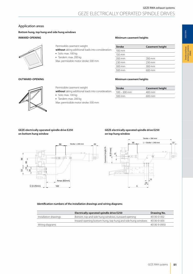
51
GEZ
E RW
A
66 22
Amax [82mm]
165Ü (0-25mm)
20
1460
5396
66 22
A
13
30
B[5
1mm
]
15
GEZE RWA systems
Smok
e an
d he
at
extr
actio
n sy
stem
s (R
WA
)
GEZE RWA exhaust systems
GEZE ElECTRiCAlly OPERATEd SPiNdlE dRiVES
Application areas
Bottom hung, top hung and side hung windows
INWARD-OPENING
OUTWARD-OPENING
Permissible casement weight without taking additional loads into consideration:j Solo: max. 100 kgj Tandem: max. 200 kgMax. permissible motor stroke: 500 mm
Permissible casement weight without taking additional loads into consideration:j Solo: max. 100 kgj Tandem: max. 200 kgMax. permissible motor stroke: 500 mm
Minimum casement heights
Stroke Casement height100 mm
150 mm
200 mm 200 mm
230 mm 230 mm
300 mm 300 mm
500 mm 600 mm
Minimum casement heights
Stroke Casement height100 – 300 mm 400 mm
500 mm 600 mm
Stroke + 240 mm
Stroke + 306 mm
l = Stroke + 240 mm
Case
men
t hei
ght F
h
GEZE electrically operated spindle drive E250 on bottom hung window
GEZE electrically operated spindle drive E250 on top hung window
Identification numbers of the installation drawings and wiring diagrams
Electrically operated spindle drive E250 Drawing No.installation drawings Bottom, top and side hung windows, outward opening 45130-0-002
inward-opening bottom hung, top hung and side hung windows 45130-0-003
Wiring diagrams 45130-9-0950
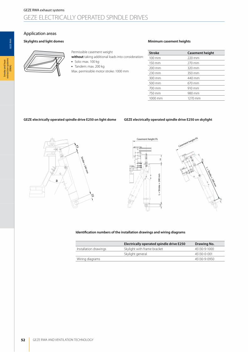
52
GEZ
E RW
A
a
43
22
66
22
22
66
GEZE RWA ANd VENTilATiON TEChNOlOGy
Smok
e an
d he
at
extr
actio
n sy
stem
s (R
WA
)
Casement height Fh
Casement height Fh
l = Stroke + 240 mm
l =
Stro
ke +
240
mm
Stroke + 240 mm
Skylights and light domes
GEZE electrically operated spindle drive E250 on light dome GEZE electrically operated spindle drive E250 on skylight
Permissible casement weight without taking additional loads into consideration:j Solo: max. 100 kgj Tandem: max. 200 kgMax. permissible motor stroke: 1000 mm
Minimum casement heights
Stroke Casement height100 mm 220 mm
150 mm 270 mm
200 mm 320 mm
230 mm 350 mm
300 mm 440 mm
500 mm 670 mm
700 mm 910 mm
750 mm 980 mm
1000 mm 1270 mm
GEZE RWA exhaust systems
GEZE ElECTRiCAlly OPERATEd SPiNdlE dRiVES
Application areas
Identification numbers of the installation drawings and wiring diagrams
Electrically operated spindle drive E250 Drawing No.installation drawings Skylight with frame bracket 45130-9-1000
Skylight general 45130-0-001
Wiring diagrams 45130-9-0950
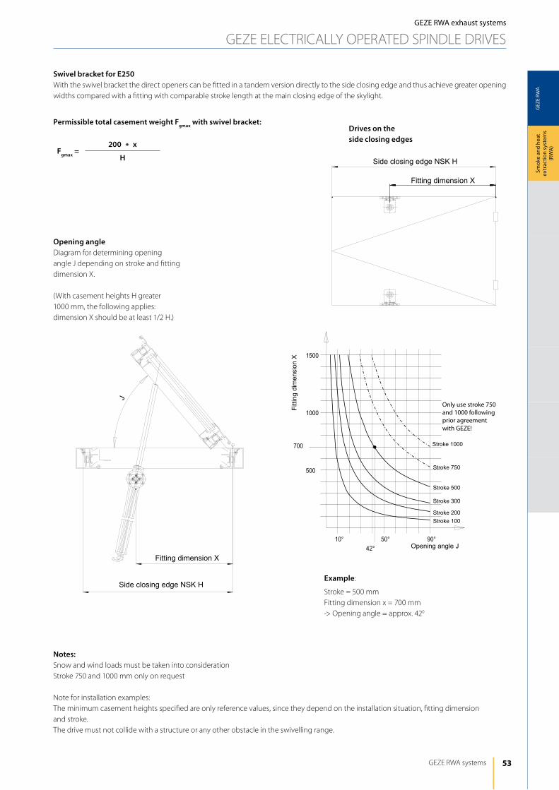
53
GEZ
E RW
A
J
GEZE RWA systems
Smok
e an
d he
at
extr
actio
n sy
stem
s (R
WA
)
GEZE RWA exhaust systems
GEZE ElECTRiCAlly OPERATEd SPiNdlE dRiVES
Fgmax =200 x
H
Permissible total casement weight Fgmax with swivel bracket:
Swivel bracket for E250With the swivel bracket the direct openers can be fitted in a tandem version directly to the side closing edge and thus achieve greater opening widths compared with a fitting with comparable stroke length at the main closing edge of the skylight.
Notes:Snow and wind loads must be taken into considerationStroke 750 and 1000 mm only on request
Note for installation examples:The minimum casement heights specified are only reference values, since they depend on the installation situation, fitting dimension and stroke.The drive must not collide with a structure or any other obstacle in the swivelling range.
Opening anglediagram for determining opening angle J depending on stroke and fitting dimension X.
(With casement heights h greater 1000 mm, the following applies: dimension X should be at least 1/2 h.)
*
Fitti
ng d
imen
sion
X
Only use stroke 750 and 1000 following prior agreement with GEZE!
Stroke 1000
Stroke 750
Stroke 500
Stroke 300
Stroke 200Stroke 100
Opening angle J
Fitting dimension X
Drives on the side closing edges
Example:
Stroke = 500 mmFitting dimension x = 700 mm-> Opening angle = approx. 420
Fitting dimension X
Side closing edge NSK H
Side closing edge NSK H
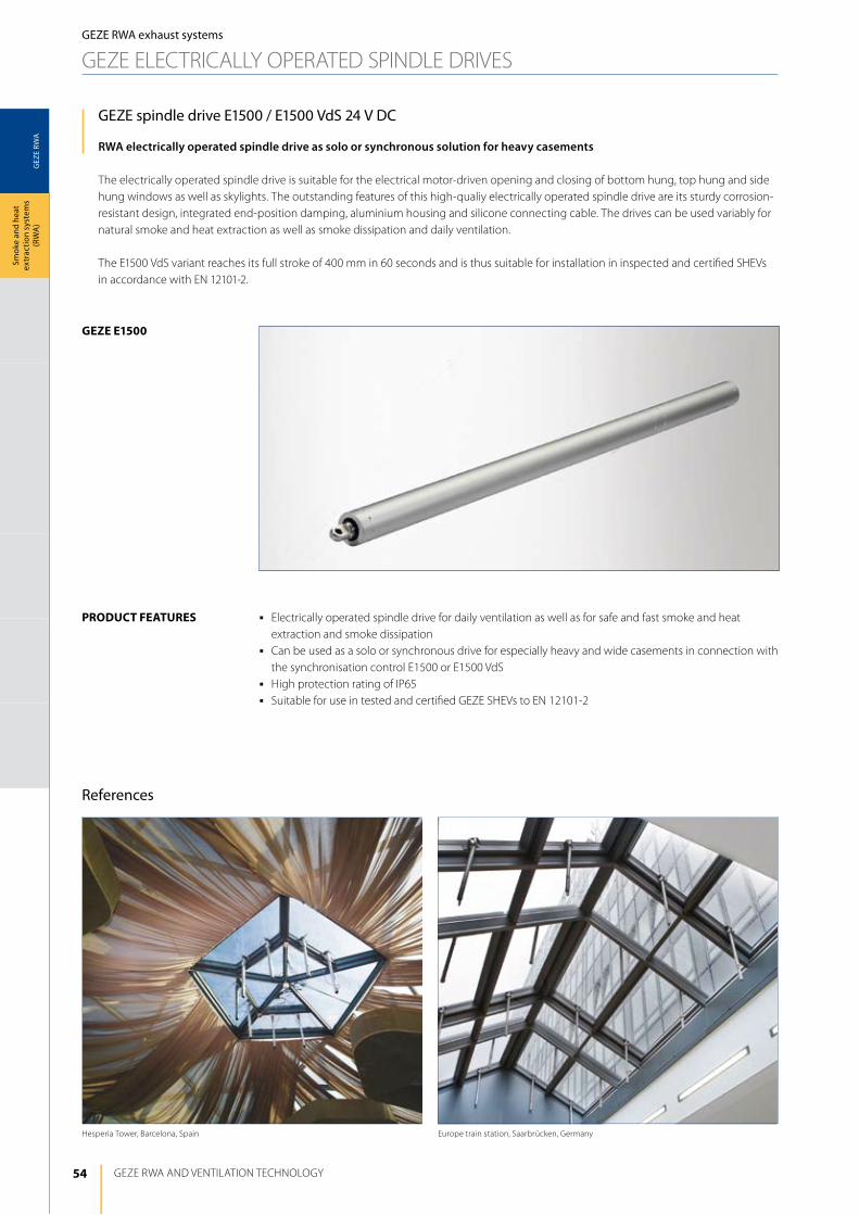
54
GEZ
E RW
A
geze e1500
Europe train station, Saarbrücken, Germanyhesperia Tower, Barcelona, Spain
GEZE RWA ANd VENTilATiON TEChNOlOGy
Smok
e an
d he
at
extr
actio
n sy
stem
s (R
WA
)
GEZE spindle drive E1500 / E1500 VdS 24 V DC
RWA electrically operated spindle drive as solo or synchronous solution for heavy casements
The electrically operated spindle drive is suitable for the electrical motor-driven opening and closing of bottom hung, top hung and side hung windows as well as skylights. The outstanding features of this high-qualiy electrically operated spindle drive are its sturdy corrosion-resistant design, integrated end-position damping, aluminium housing and silicone connecting cable. The drives can be used variably for natural smoke and heat extraction as well as smoke dissipation and daily ventilation.
The E1500 VdS variant reaches its full stroke of 400 mm in 60 seconds and is thus suitable for installation in inspected and certified ShEVs in accordance with EN 12101-2.
j Electrically operated spindle drive for daily ventilation as well as for safe and fast smoke and heat extraction and smoke dissipation
j Can be used as a solo or synchronous drive for especially heavy and wide casements in connection with the synchronisation control E1500 or E1500 VdS
j high protection rating of iP65j Suitable for use in tested and certified GEZE ShEVs to EN 12101-2
product FeAtureS
GEZE RWA exhaust systems
GEZE ElECTRiCAlly OPERATEd SPiNdlE dRiVES
References

55
GEZ
E RW
A
GEZE RWA systems
Smok
e an
d he
at
extr
actio
n sy
stem
s (R
WA
)
GEZE RWA exhaust systems
GEZE ElECTRiCAlly OPERATEd SPiNdlE dRiVES
Description Version Id. No. Id. No. Id. No. Id. No.E1500 VdS E1500 Solo E1500 Syncro
Stroke 300 mm
EV1 (silver) 121167 121201
white RAl 9016 121168 121202
to RAl 121169 121203
Stroke 400 mm
EV1 (silver) 121294
white RAl 9016 121295
to RAl 121296
Stroke 500 mm
EV1 (silver) 121170 121204
white RAl 9016 121191 121205
to RAl 121192 121206
Stroke 750 mm
EV1 (silver) 121193 121207
white RAl 9016 121194 121208
to RAl 121195 121209
Stroke 1000 mm
EV1 (silver) 121196 121210
white RAl 9016 121197 121211
to RAl 121198 121212
Special versionEV1 (silver) 121199 121213
to RAl 121200 121214
Synchronous control unit E1500 121271
Synchronous control unit E1500 VdS 121293
load cut-off E1500 VdS 121391
Clamp ring E1500
EV1 (silver) 121215
white RAl 9016 121216
to RAl 121217
Casement bracket E1500
EV1 (silver) 121218
white RAl 9016 121219
to RAl 121220
Casement bracket E1500 FS(with limited horizontal space for casement bracket E1500)
EV1 (silver) 123085
white RAl 9016 123086
to RAl 123087
Skylight bracket E1500 h40(mainly for flat-closing windows)
EV1 (silver) 121221
white RAl 9016 121222
to RAl 121223
Skylight bracket E1500 h86(mainly for windows with projection)
EV1 (silver) 121224
white RAl 9016 121225
to RAl 121226
Bracket E1500 for bottom, top and side hung windows
EV1 (silver) 123088
white RAl 9016 123089
to RAl 123090
ORDER INFORMATION – GEZE ELECTRICALLy OPERATED SPINDLE DRIVES E1500 / 24 V DC
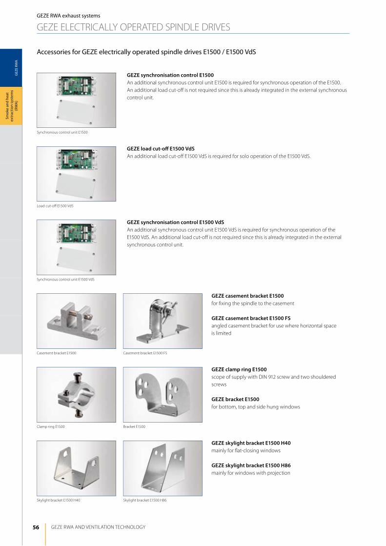
56
GEZ
E RW
A
GEZE RWA ANd VENTilATiON TEChNOlOGy
Smok
e an
d he
at
extr
actio
n sy
stem
s (R
WA
)
Accessories for GEZE electrically operated spindle drives E1500 / E1500 VdS
GEZE synchronisation control E1500An additional synchronous control unit E1500 is required for synchronous operation of the E1500. An additional load cut-off is not required since this is already integrated in the external synchronous control unit.
GEZE load cut-off E1500 VdSAn additional load cut-off E1500 VdS is required for solo operation of the E1500 VdS.
GEZE synchronisation control E1500 VdSAn additional synchronous control unit E1500 VdS is required for synchronous operation of the E1500 VdS. An additional load cut-off is not required since this is already integrated in the external synchronous control unit.
GEZE casement bracket E1500for fixing the spindle to the casement
GEZE casement bracket E1500 FSangled casement bracket for use where horizontal space is limited
GEZE clamp ring E1500scope of supply with diN 912 screw and two shouldered screws
GEZE bracket E1500for bottom, top and side hung windows
GEZE skylight bracket E1500 H40mainly for flat-closing windows
GEZE skylight bracket E1500 H86mainly for windows with projection
GEZE RWA exhaust systems
GEZE ElECTRiCAlly OPERATEd SPiNdlE dRiVES
Skylight bracket E1500 h40
Clamp ring E1500 Bracket E1500
Skylight bracket E1500 h86
load cut-off E1500 VdS
Synchronous control unit E1500
Casement bracket E1500 Casement bracket E1500 FS
Synchronous control unit E1500 VdS
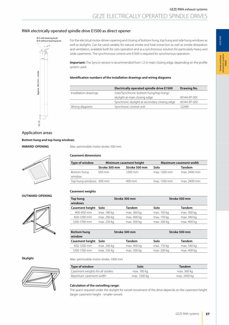
57
GEZ
E RW
A
n 36
n 18
8
19
min
.25
GEZE RWA systems
Smok
e an
d he
at
extr
actio
n sy
stem
s (R
WA
)
RWA electrically operated spindle drive E1500 as direct opener
GEZE RWA exhaust systems
GEZE ElECTRiCAlly OPERATEd SPiNdlE dRiVES
For the electrical motor-driven opening and closing of bottom hung, top hung and side hung windows as well as skylights. Can be used variably for natural smoke and heat extraction as well as smoke dissipation and ventilation, available both for solo operation and as a synchronous solution for particularly heavy and wide casements. The synchronous control unit E1500 is required for synchronous operation.
Important: The Syncro version is recommended from 1.2 m main closing edge, depending on the profile system used.
Application areas
Bottom hung and top hung windows
INWARD-OPENING
Skylight
OUTWARD-OPENING
Max. permissible motor stroke: 500 mm
Casement dimensions
Type of window Minimum casement height Maximum casement widthStroke 300 mm Stroke 500 mm Solo Tandem
Bottom hung window
650 mm 1200 mm max. 1200 mm max. 2400 mm
Top hung windows 400 mm 400 mm max. 1200 mm max. 2400 mm
Max. permissible motor stroke: 1000 mm
Type of window Solo TandemCasement weights for all strokes max. 180 kg max. 360 kg
Maximum casement width max. 1200 kg max. 2400 kg
Calculation of the swivelling range:The space required under the skylight for swivel movement of the drive depends on the casement height (larger casement height - smaller swivel).
Casement weights
Top hung windows
Stroke 300 mm Stroke 500 mm
Casement height Solo Tandem Solo Tandem400-650 mm max. 180 kg max. 360 kg max. 150 kg max. 300 kg
650-1200 mm max. 200 kg max. 400 kg max. 170 kg max. 340 kg
1200-1700 mm max. 250 kg max. 500 kg max. 200 kg max. 400 kg
Bottom hung window
Stroke 300 mm Stroke 500 mm
Casement height Solo Tandem Solo Tandem650-1200 mm max. 200 kg max. 400 kg max. 170 kg max. 340 kg
1200-1700 mm max. 250 kg max. 500 kg max. 200 kg max. 400 kg
Identification numbers of the installation drawings and wiring diagrams
Electrically operated spindle drive E1500 Drawing No.installation drawings Solo/Synchronic bottom hung/top hung/
skylight at main closing edge 45144-EP-001
Synchronic skylight at secondary closing edge 45144-EP-002
Wiring diagrams Synchronic control unit 122481
Ø 6 with bearing bushØ 8 without bearing bush
App
rox.
302
mm
+ s
trok
e
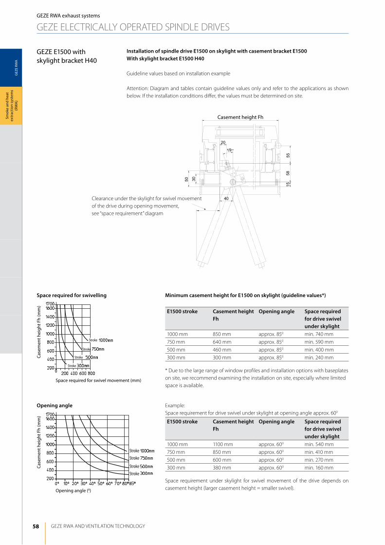
58
GEZ
E RW
A
55
3040
50
20
5815
19~
GEZE RWA ANd VENTilATiON TEChNOlOGy
Smok
e an
d he
at
extr
actio
n sy
stem
s (R
WA
)GEZE RWA exhaust systems
GEZE ElECTRiCAlly OPERATEd SPiNdlE dRiVES
Minimum casement height for E1500 on skylight (guideline values*)
E1500 stroke Casement height Fh
Opening angle Space required for drive swivel under skylight
1000 mm 850 mm approx. 850 min. 740 mm
750 mm 640 mm approx. 850 min. 590 mm
500 mm 460 mm approx. 850 min. 400 mm
300 mm 300 mm approx. 850 min. 240 mm
* due to the large range of window profiles and installation options with baseplates on site, we recommend examining the installation on site, especially where limited space is available.
Example: Space requirement for drive swivel under skylight at opening angle approx. 600
E1500 stroke Casement height Fh
Opening angle Space required for drive swivel under skylight
1000 mm 1100 mm approx. 600 min. 540 mm
750 mm 850 mm approx. 600 min. 410 mm
500 mm 600 mm approx. 600 min. 270 mm
300 mm 380 mm approx. 600 min. 160 mm
Space requirement under skylight for swivel movement of the drive depends on casement height (larger casement height = smaller swivel).
Installation of spindle drive E1500 on skylight with casement bracket E1500With skylight bracket E1500 H40
Guideline values based on installation example
Attention: diagram and tables contain guideline values only and refer to the applications as shown below. if the installation conditions differ, the values must be determined on site.
Casement height Fh
Clearance under the skylight for swivel movement of the drive during opening movement, see “space requirement” diagram
Space required for swivelling
Opening angle
Space required for swivel movement (mm)
Opening angle (0)
Case
men
t hei
ght F
h (m
m)
Case
men
t hei
ght F
h (m
m)
Stroke
Stroke
Stroke
Stroke
Stroke
Stroke
Stroke
Stroke
GEZE E1500 withskylight bracket H40
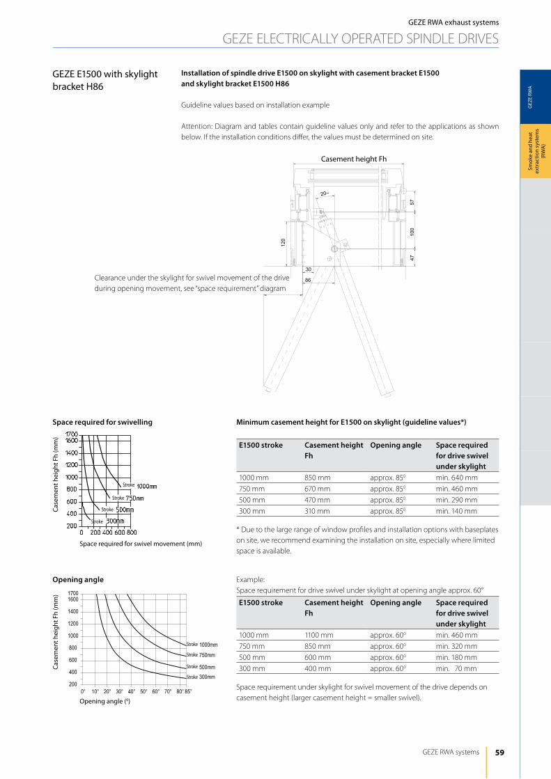
59
GEZ
E RW
A
4710
057
120
30
86
20~
300mm
500mm
750mm
1000mm
17001600
1400
1200
1000
800
600
400
2000° 10° 20° 30° 40° 50° 60° 70° 80° 85°
GEZE RWA systems
Smok
e an
d he
at
extr
actio
n sy
stem
s (R
WA
)
GEZE E1500 with skylight bracket H86
Minimum casement height for E1500 on skylight (guideline values*)
E1500 stroke Casement height Fh
Opening angle Space required for drive swivel under skylight
1000 mm 850 mm approx. 850 min. 640 mm
750 mm 670 mm approx. 850 min. 460 mm
500 mm 470 mm approx. 850 min. 290 mm
300 mm 310 mm approx. 850 min. 140 mm
* due to the large range of window profiles and installation options with baseplates on site, we recommend examining the installation on site, especially where limited space is available.
Example: Space requirement for drive swivel under skylight at opening angle approx. 60°
E1500 stroke Casement height Fh
Opening angle Space required for drive swivel under skylight
1000 mm 1100 mm approx. 600 min. 460 mm
750 mm 850 mm approx. 600 min. 320 mm
500 mm 600 mm approx. 600 min. 180 mm
300 mm 400 mm approx. 600 min. 170 mm
Space requirement under skylight for swivel movement of the drive depends on casement height (larger casement height = smaller swivel).
Installation of spindle drive E1500 on skylight with casement bracket E1500and skylight bracket E1500 H86
Guideline values based on installation example
Attention: diagram and tables contain guideline values only and refer to the applications as shown below. if the installation conditions differ, the values must be determined on site.
Casement height Fh
Space required for swivelling
Opening angle
Space required for swivel movement (mm)
Opening angle (0)
Case
men
t hei
ght F
h (m
m)
Case
men
t hei
ght F
h (m
m)
Stroke
Stroke
Stroke
Stroke
Stroke
Stroke
Stroke
Stroke
Clearance under the skylight for swivel movement of the drive during opening movement, see “space requirement” diagram
GEZE RWA exhaust systems
GEZE ElECTRiCAlly OPERATEd SPiNdlE dRiVES

60
GEZ
E RW
A
n 36
n 18
8
19
min.25
GEZE RWA ANd VENTilATiON TEChNOlOGy
Smok
e an
d he
at
extr
actio
n sy
stem
s (R
WA
)GEZE RWA exhaust systems
GEZE ElECTRiCAlly OPERATEd SPiNdlE dRiVES
RWA – electrically operated spindle drive E1500 VdS as direct opener
The E1500 VdS, tested to VdS 2580, is suitable for the electric motor-operated opening and closing of bottom hung, top hung, side hung windows, skylights and light domes. it can be variable used for natural smoke and heat extraction and smoke dissipation as well as for ventilation. Can be used both as a solo drive and a synchronous solution for particularly heavy and wide casements. in addition, the drive is suitable for installation in tested and certified GEZE ShEVs to EN 12101-2. The synchronic control unit E1500 VdS is required for synchronous drive.
Important: The Syncro version is recommended from 1.2 m main closing edge, depending on the profile system used.
Application areas
Bottom hung and top hung windows
INWARD-OPENING
Skylight
OUTWARD-OPENING
Motor stroke: 400 mm
Casement dimensions
Type of window Minimum casement height Maximum casement widthStroke 400 mm Solo Tandem
Bottom hung window 950 mm max. 1200 mm max. 2400 mm
Top hung windows 400 mm max. 1200 mm max. 2400 mm
Motor stroke: 400 mm
Type of window Solo TandemCasement weights for all strokes max. 180 kg max. 360 kg
Maximum casement width max. 1200 kg max. 2400 kg
Calculation of the swivelling range:The space required under the skylight for swivel movement of the drive depends on the casement height (larger casement height - smaller swivel).
Casement weights
Top hung windows Stroke 400 mmCasement height Solo Tandem
400-950 mm max. 170 kg max. 340 kg
950-1700 mm max. 250 kg max. 500 kg
Bottom hung window Stroke 400 mmCasement height Solo Tandem
950-1700 mm max. 250 kg max. 500 kg
Identification numbers of the installation drawings and wiring diagrams
Electrically operated spindle drive E1500 VdS Drawing No.installation drawings Solo/Synchronic bottom hung/top hung/
skylight at main closing edge 45144-EP-003
Synchronic skylight at secondary closing edge 45144-EP-004
Wiring diagrams Synchronic control unit 122483
load cut-off 122482
Ø 6 with bearing bushØ 8 without bearing bush
App
rox.
302
mm
+ s
trok
e
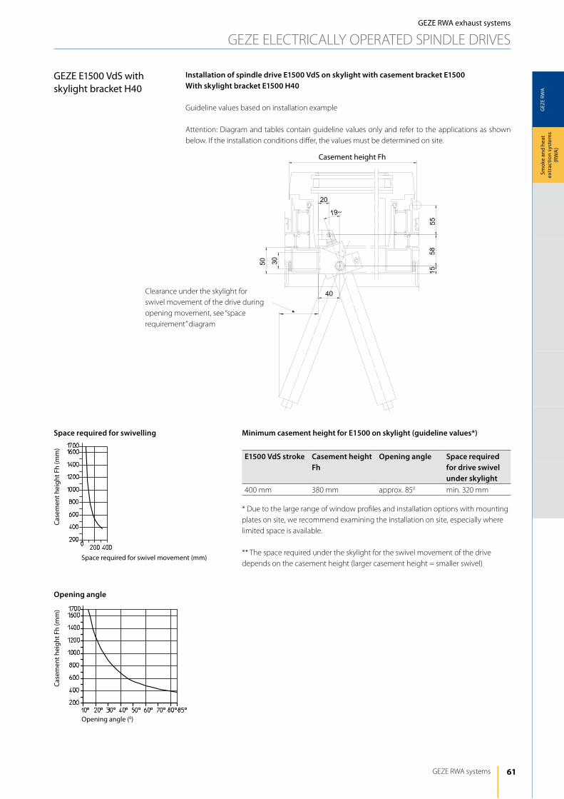
61
GEZ
E RW
A
55
30
40
50
20
5815
19~
GEZE RWA systems
Smok
e an
d he
at
extr
actio
n sy
stem
s (R
WA
)
Minimum casement height for E1500 on skylight (guideline values*)
E1500 VdS stroke Casement height Fh
Opening angle Space required for drive swivel under skylight
400 mm 380 mm approx. 850 min. 320 mm
* due to the large range of window profiles and installation options with mounting plates on site, we recommend examining the installation on site, especially where limited space is available.
** The space required under the skylight for the swivel movement of the drive depends on the casement height (larger casement height = smaller swivel)
Installation of spindle drive E1500 VdS on skylight with casement bracket E1500With skylight bracket E1500 H40
Guideline values based on installation example
Attention: diagram and tables contain guideline values only and refer to the applications as shown below. if the installation conditions differ, the values must be determined on site.
Casement height Fh
Space required for swivelling
Opening angle
Space required for swivel movement (mm)
Opening angle (0)
Case
men
t hei
ght F
h (m
m)
Case
men
t hei
ght F
h (m
m)
Clearance under the skylight for swivel movement of the drive during opening movement, see “space requirement” diagram
GEZE RWA exhaust systems
GEZE ElECTRiCAlly OPERATEd SPiNdlE dRiVES
GEZE E1500 VdS with skylight bracket H40
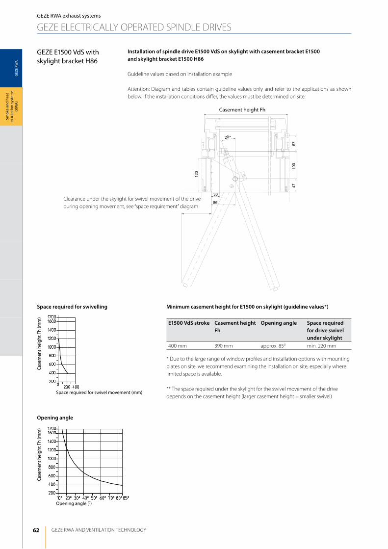
62
GEZ
E RW
A
4710
057
120
30
86
20~
GEZE RWA ANd VENTilATiON TEChNOlOGy
Smok
e an
d he
at
extr
actio
n sy
stem
s (R
WA
)
Minimum casement height for E1500 on skylight (guideline values*)
E1500 VdS stroke Casement height Fh
Opening angle Space required for drive swivel under skylight
400 mm 390 mm approx. 850 min. 220 mm
* due to the large range of window profiles and installation options with mounting plates on site, we recommend examining the installation on site, especially where limited space is available.
** The space required under the skylight for the swivel movement of the drive depends on the casement height (larger casement height = smaller swivel)
Installation of spindle drive E1500 VdS on skylight with casement bracket E1500and skylight bracket E1500 H86
Guideline values based on installation example
Attention: diagram and tables contain guideline values only and refer to the applications as shown below. if the installation conditions differ, the values must be determined on site.
Casement height Fh
Space required for swivelling
Opening angle
Space required for swivel movement (mm)
Opening angle (0)
Case
men
t hei
ght F
h (m
m)
Case
men
t hei
ght F
h (m
m)
GEZE E1500 VdS with skylight bracket H86
GEZE RWA exhaust systems
GEZE ElECTRiCAlly OPERATEd SPiNdlE dRiVES
Clearance under the skylight for swivel movement of the drive during opening movement, see “space requirement” diagram
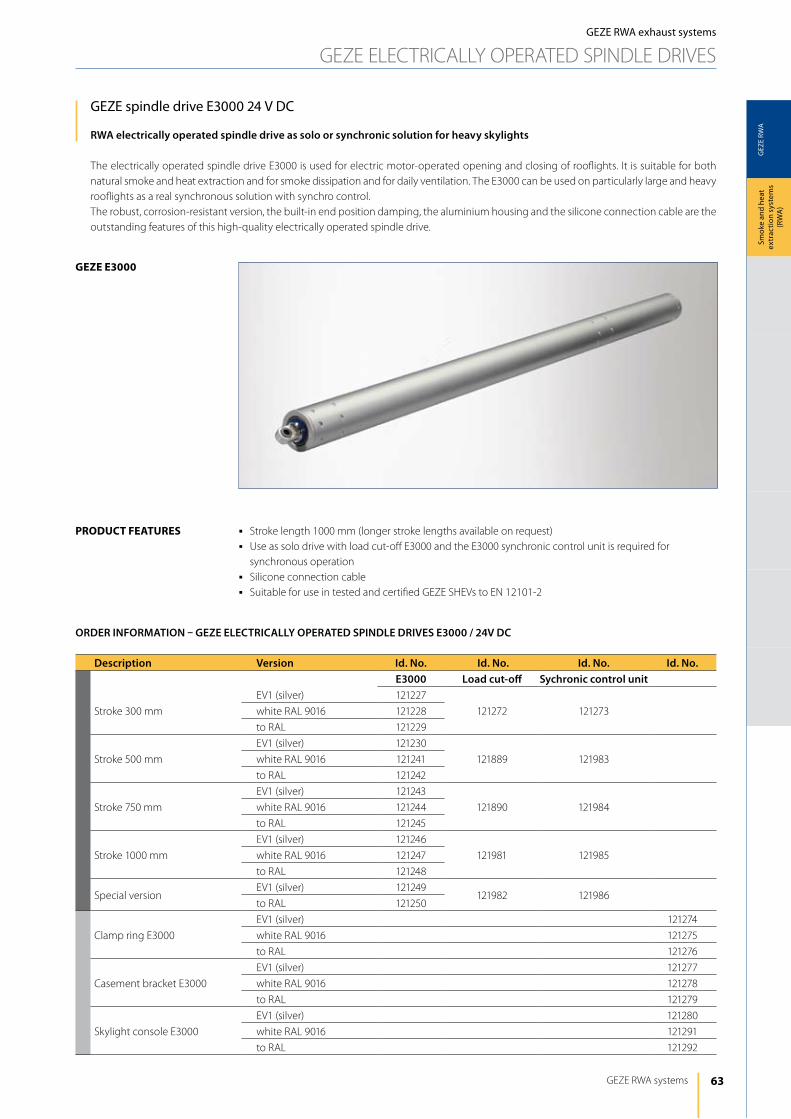
63
GEZ
E RW
A
geze e3000
GEZE RWA systems
Smok
e an
d he
at
extr
actio
n sy
stem
s (R
WA
)
GEZE spindle drive E3000 24 V DC
RWA electrically operated spindle drive as solo or synchronic solution for heavy skylights
The electrically operated spindle drive E3000 is used for electric motor-operated opening and closing of rooflights. it is suitable for both natural smoke and heat extraction and for smoke dissipation and for daily ventilation. The E3000 can be used on particularly large and heavy rooflights as a real synchronous solution with synchro control.The robust, corrosion-resistant version, the built-in end position damping, the aluminium housing and the silicone connection cable are the outstanding features of this high-quality electrically operated spindle drive.
product FeAtureS
GEZE RWA exhaust systems
GEZE ElECTRiCAlly OPERATEd SPiNdlE dRiVES
j Stroke length 1000 mm (longer stroke lengths available on request) j Use as solo drive with load cut-off E3000 and the E3000 synchronic control unit is required for
synchronous operationj Silicone connection cablej Suitable for use in tested and certified GEZE ShEVs to EN 12101-2
Description Version Id. No. Id. No. Id. No. Id. No.E3000 Load cut-off Sychronic control unit
Stroke 300 mm
EV1 (silver) 121227
121272 121273white RAl 9016 121228
to RAl 121229
Stroke 500 mm
EV1 (silver) 121230
121889 121983white RAl 9016 121241
to RAl 121242
Stroke 750 mm
EV1 (silver) 121243
121890 121984white RAl 9016 121244
to RAl 121245
Stroke 1000 mm
EV1 (silver) 121246
121981 121985white RAl 9016 121247
to RAl 121248
Special versionEV1 (silver) 121249
121982 121986to RAl 121250
Clamp ring E3000
EV1 (silver) 121274
white RAl 9016 121275
to RAl 121276
Casement bracket E3000
EV1 (silver) 121277
white RAl 9016 121278
to RAl 121279
Skylight console E3000
EV1 (silver) 121280
white RAl 9016 121291
to RAl 121292
ORDER INFORMATION – GEZE ELECTRICALLy OPERATED SPINDLE DRIVES E3000 / 24V DC
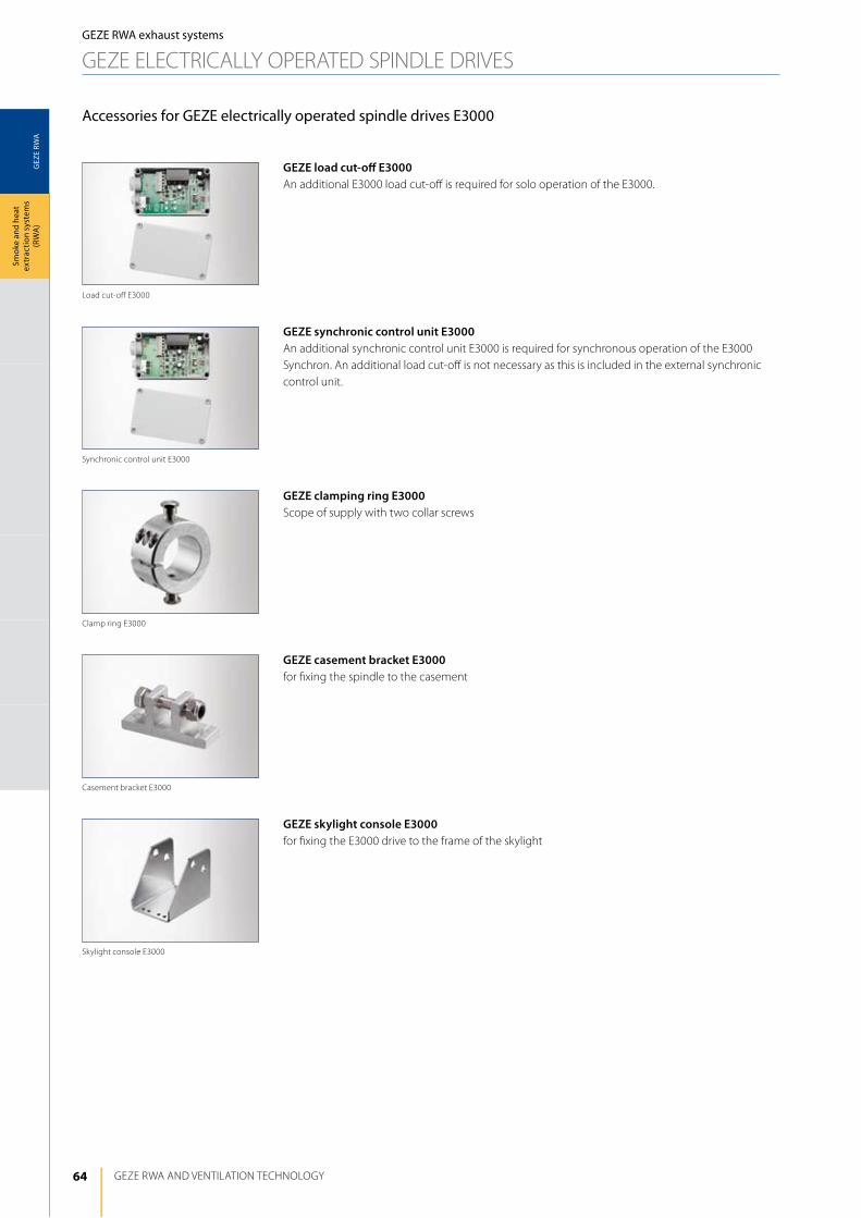
64
GEZ
E RW
A
GEZE RWA ANd VENTilATiON TEChNOlOGy
Smok
e an
d he
at
extr
actio
n sy
stem
s (R
WA
)
Accessories for GEZE electrically operated spindle drives E3000
GEZE load cut-off E3000An additional E3000 load cut-off is required for solo operation of the E3000.
GEZE synchronic control unit E3000An additional synchronic control unit E3000 is required for synchronous operation of the E3000 Synchron. An additional load cut-off is not necessary as this is included in the external synchronic control unit.
GEZE clamping ring E3000Scope of supply with two collar screws
GEZE casement bracket E3000for fixing the spindle to the casement
GEZE skylight console E3000for fixing the E3000 drive to the frame of the skylight
GEZE RWA exhaust systems
GEZE ElECTRiCAlly OPERATEd SPiNdlE dRiVES
Skylight console E3000
Casement bracket E3000
Clamp ring E3000
Synchronic control unit E3000
load cut-off E3000
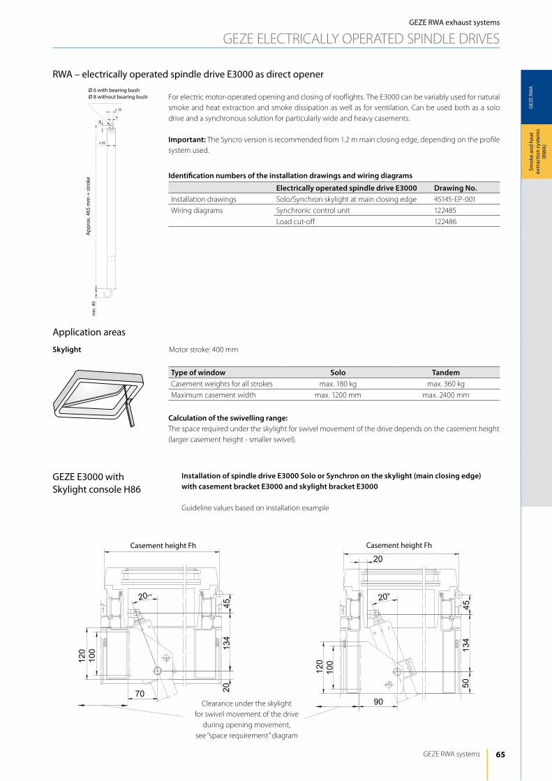
65
GEZ
E RW
A
45
120
100
70 2013
4
20~
20
4513
4
90
100
120
50
20°
n 50
n 18
8
24
min.40
GEZE RWA systems
Smok
e an
d he
at
extr
actio
n sy
stem
s (R
WA
)
GEZE RWA exhaust systems
GEZE ElECTRiCAlly OPERATEd SPiNdlE dRiVES
RWA – electrically operated spindle drive E3000 as direct opener
For electric motor-operated opening and closing of rooflights. The E3000 can be variably used for natural smoke and heat extraction and smoke dissipation as well as for ventilation. Can be used both as a solo drive and a synchronous solution for particularly wide and heavy casements.
Important: The Syncro version is recommended from 1.2 m main closing edge, depending on the profile system used.
Application areas
Skylight Motor stroke: 400 mm
Type of window Solo TandemCasement weights for all strokes max. 180 kg max. 360 kg
Maximum casement width max. 1200 mm max. 2400 mm
Calculation of the swivelling range:The space required under the skylight for swivel movement of the drive depends on the casement height (larger casement height - smaller swivel).
Identification numbers of the installation drawings and wiring diagrams
Electrically operated spindle drive E3000 Drawing No.installation drawings Solo/Synchron skylight at main closing edge 45145-EP-001
Wiring diagrams Synchronic control unit 122485
load cut-off 122486
Installation of spindle drive E3000 Solo or Synchron on the skylight (main closing edge)with casement bracket E3000 and skylight bracket E3000
Guideline values based on installation example
GEZE E3000 with Skylight console H86
Clearance under the skylight for swivel movement of the drive
during opening movement, see “space requirement” diagram
Casement height Fh Casement height Fh
Ø 6 with bearing bushØ 8 without bearing bush
App
rox.
465
mm
+ s
trok
e
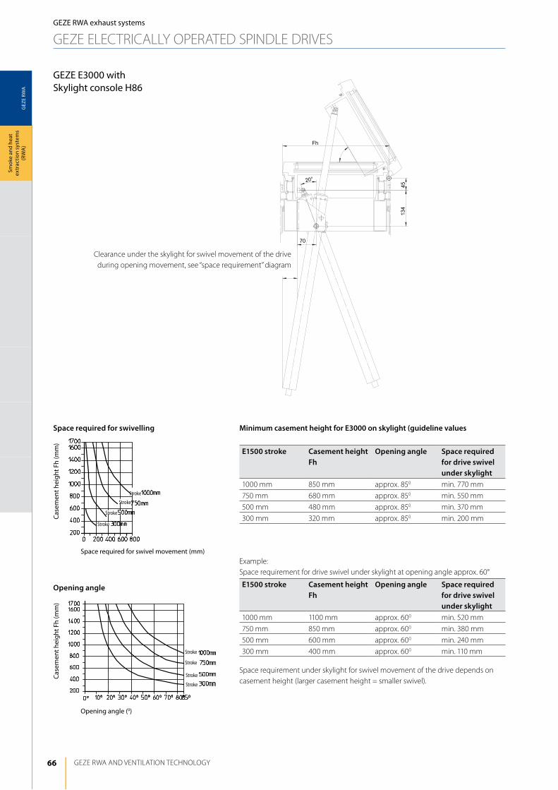
66
GEZ
E RW
A
Fh
134
45
20°
70
�
GEZE RWA ANd VENTilATiON TEChNOlOGy
Smok
e an
d he
at
extr
actio
n sy
stem
s (R
WA
)
Minimum casement height for E3000 on skylight (guideline values
E1500 stroke Casement height Fh
Opening angle Space required for drive swivel under skylight
1000 mm 850 mm approx. 850 min. 770 mm
750 mm 680 mm approx. 850 min. 550 mm
500 mm 480 mm approx. 850 min. 370 mm
300 mm 320 mm approx. 850 min. 200 mm
Example: Space requirement for drive swivel under skylight at opening angle approx. 60°
E1500 stroke Casement height Fh
Opening angle Space required for drive swivel under skylight
1000 mm 1100 mm approx. 600 min. 520 mm
750 mm 850 mm approx. 600 min. 380 mm
500 mm 600 mm approx. 600 min. 240 mm
300 mm 400 mm approx. 600 min. 110 mm
Space requirement under skylight for swivel movement of the drive depends on casement height (larger casement height = smaller swivel).
Space required for swivelling
Opening angle
Space required for swivel movement (mm)
Opening angle (0)
Case
men
t hei
ght F
h (m
m)
Case
men
t hei
ght F
h (m
m)
Stroke
Stroke
Stroke
Stroke
Stroke
Stroke
Stroke
Stroke
GEZE E3000 with Skylight console H86
GEZE RWA exhaust systems
GEZE ElECTRiCAlly OPERATEd SPiNdlE dRiVES
Clearance under the skylight for swivel movement of the drive during opening movement, see “space requirement” diagram
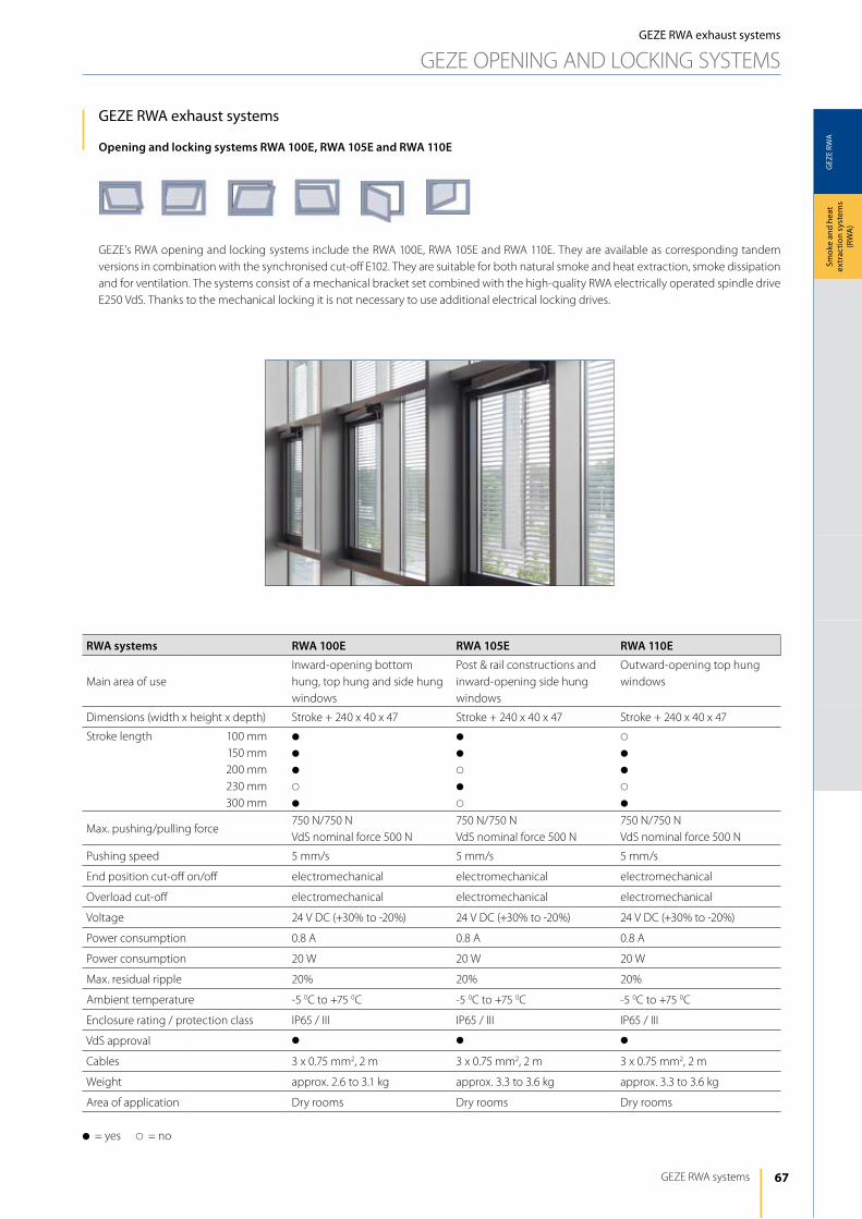
67
GEZ
E RW
A
GEZE RWA systems
Smok
e an
d he
at
extr
actio
n sy
stem
s (R
WA
)
GEZE RWA exhaust systems
GEZE OPENiNG ANd lOCKiNG SySTEMS
GEZE RWA exhaust systems
Opening and locking systems RWA 100E, RWA 105E and RWA 110E
GEZE's RWA opening and locking systems include the RWA 100E, RWA 105E and RWA 110E. They are available as corresponding tandem versions in combination with the synchronised cut-off E102. They are suitable for both natural smoke and heat extraction, smoke dissipation and for ventilation. The systems consist of a mechanical bracket set combined with the high-quality RWA electrically operated spindle drive E250 VdS. Thanks to the mechanical locking it is not necessary to use additional electrical locking drives.
RWA systems RWA 100E RWA 105E RWA 110E
Main area of useinward-opening bottom hung, top hung and side hung windows
Post & rail constructions and inward-opening side hung windows
Outward-opening top hung windows
dimensions (width x height x depth) Stroke + 240 x 40 x 47 Stroke + 240 x 40 x 47 Stroke + 240 x 40 x 47
Stroke length 100 mm150 mm200 mm230 mm300 mm
d
d
d
s
d
d
d
s
d
s
s
d
d
s
d
Max. pushing/pulling force750 N/750 NVdS nominal force 500 N
750 N/750 NVdS nominal force 500 N
750 N/750 NVdS nominal force 500 N
Pushing speed 5 mm/s 5 mm/s 5 mm/s
End position cut-off on/off electromechanical electromechanical electromechanical
Overload cut-off electromechanical electromechanical electromechanical
Voltage 24 V dC (+30% to -20%) 24 V dC (+30% to -20%) 24 V dC (+30% to -20%)
Power consumption 0.8 A 0.8 A 0.8 A
Power consumption 20 W 20 W 20 W
Max. residual ripple 20% 20% 20%
Ambient temperature -5 0C to +75 0C -5 0C to +75 0C -5 0C to +75 0C
Enclosure rating / protection class iP65 / iii iP65 / iii iP65 / iii
VdS approval d d d
Cables 3 x 0.75 mm2, 2 m 3 x 0.75 mm2, 2 m 3 x 0.75 mm2, 2 m
Weight approx. 2.6 to 3.1 kg approx. 3.3 to 3.6 kg approx. 3.3 to 3.6 kg
Area of application dry rooms dry rooms dry rooms
d= yes s= no
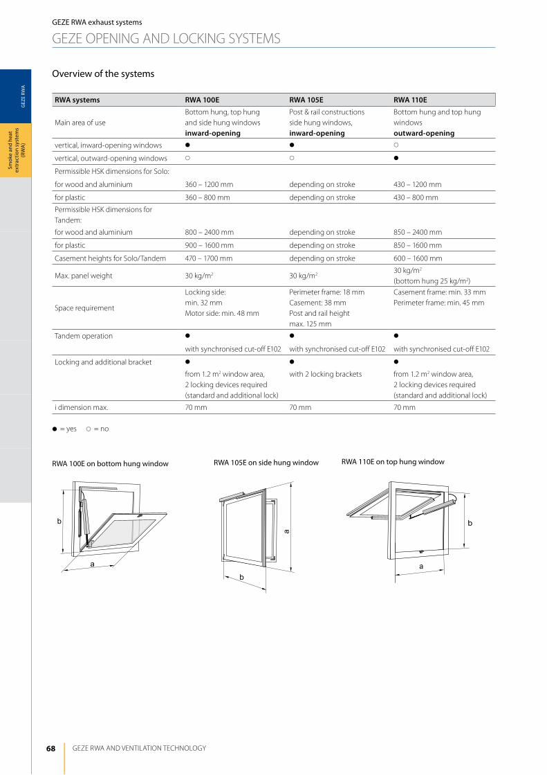
68
GEZ
E RW
A
a
b b
a
a
b
GEZE RWA ANd VENTilATiON TEChNOlOGy
Smok
e an
d he
at
extr
actio
n sy
stem
s (R
WA
)
Overview of the systems
RWA systems RWA 100E RWA 105E RWA 110E
Main area of useBottom hung, top hung and side hung windowsinward-opening
Post & rail constructions side hung windows, inward-opening
Bottom hung and top hung windows outward-opening
vertical, inward-opening windows d d s
vertical, outward-opening windows s s d
Permissible hSK dimensions for Solo:
for wood and aluminium 360 – 1200 mm depending on stroke 430 – 1200 mm
for plastic 360 – 800 mm depending on stroke 430 – 800 mm
Permissible hSK dimensions for Tandem:
for wood and aluminium 800 – 2400 mm depending on stroke 850 – 2400 mm
for plastic 900 – 1600 mm depending on stroke 850 – 1600 mm
Casement heights for Solo/Tandem 470 – 1700 mm depending on stroke 600 – 1600 mm
Max. panel weight 30 kg/m2 30 kg/m230 kg/m2 (bottom hung 25 kg/m2)
Space requirement
locking side:min. 32 mmMotor side: min. 48 mm
Perimeter frame: 18 mm Casement: 38 mm Post and rail height max. 125 mm
Casement frame: min. 33 mmPerimeter frame: min. 45 mm
Tandem operation d d d
with synchronised cut-off E102 with synchronised cut-off E102 with synchronised cut-off E102
locking and additional bracket d d d
from 1.2 m2 window area, 2 locking devices required (standard and additional lock)
with 2 locking brackets from 1.2 m2 window area, 2 locking devices required (standard and additional lock)
i dimension max. 70 mm 70 mm 70 mm
d= yes s= no
GEZE RWA exhaust systems
GEZE OPENiNG ANd lOCKiNG SySTEMS
RWA 100E on bottom hung window RWA 105E on side hung window RWA 110E on top hung window
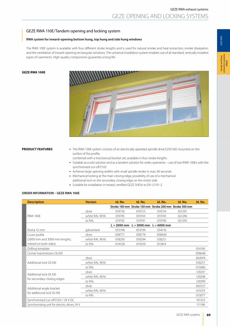
69
GEZ
E RW
A
geze rwA 100e
GEZE RWA systems
Smok
e an
d he
at
extr
actio
n sy
stem
s (R
WA
)
GEZE RWA exhaust systems
GEZE OPENiNG ANd lOCKiNG SySTEMS
GEZE RWA 110E/Tandem opening and locking system
RWA system for inward-opening bottom hung, top hung and side hung windows
The RWA 100E system is available with four different stroke lengths and is used for natural smoke and heat extraction, smoke dissipation and the ventilation of inward-opening rectangular windows. The universal installation system enables use of all standard, vertically installed types of casements. high-quality components guarantee a long life.
j The RWA 100E system consists of an electrically operated spindle drive E250 VdS mounted on the surface of the profile,
combined with a mechanical bracket set; available in four stroke lengthsj Suitable as a solo solution and as a tandem solution for wide casements – use of two RWA 100Es with the
synchronised cut-off E102j Achieves large opening widths with small spindle stroke in max. 60 secondsj Mechanical locking at the main closing edge, possibility of use of a mechanical additional lock on the secondary closing edge on the motor sidej Suitable for installation in tested, certified GEZE ShEVs to EN 12101-2
product FeAtureS
Description Version Id. No. Id. No. Id. No. Id. No. Id. No.Stroke 100 mm Stroke 150 mm Stroke 200 mm Stroke 300 mm
RWA 100E
silver 019726 019725 019724 021291
white RAl 9016 019745 019744 019743 021296
to RAl 019742 019741 019740 021295
L = 2000 mm L = 3000 mm L = 6000 mmRod ø 12 mm galvanised 053198 053199 054116
Cover profile (2000 mm and 3000 mm lengths, mitred on both sides)
silver 058771 058774 058630
white RAl 9016 018293 018294 018251
to RAl 014258 014259 013814
drilling template 014740
Corner transmission Ol100 058648
Additional lock Ol100
silver 063974
white RAl 9016 018257
to RAl 013080
Additional lock Ol100 for secondary closing edges
silver 120297
white RAl 9016 120298
to RAl 120299
Additional angle bracket for additional lock Ol100
silver 050727
white RAl 9016 015519
to RAl 013077
Synchronised cut-off E102 / 24 V dC 101323
Synchronising unit for electric drives 24 V 111198
ORDER INFORMATION – GEZE RWA 100E
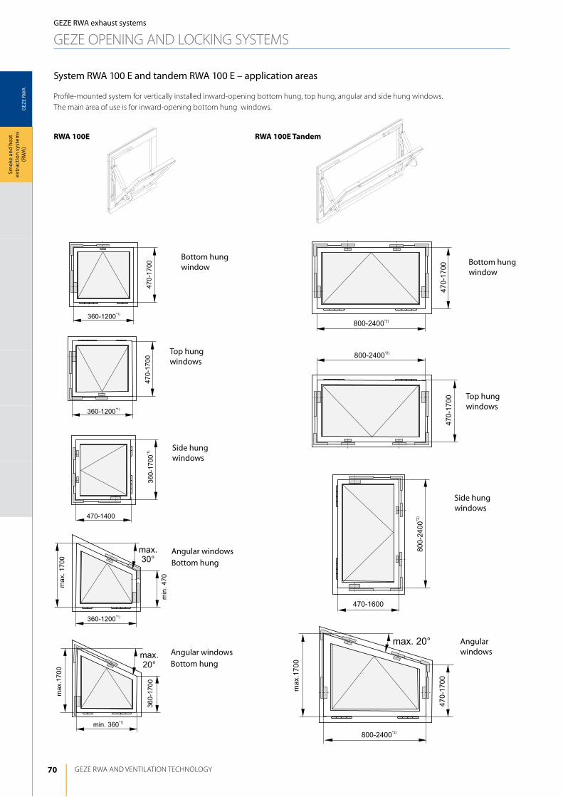
70
GEZ
E RW
A
800-
2400
*2)
470-1600
800-2400*2)
470-
1700
800-2400*2)
470-
1700
max. 20°
470-
1700
max
.170
0
800-2400*2)
GEZE RWA ANd VENTilATiON TEChNOlOGy
Smok
e an
d he
at
extr
actio
n sy
stem
s (R
WA
)
System RWA 100 E and tandem RWA 100 E – application areas
Profile-mounted system for vertically installed inward-opening bottom hung, top hung, angular and side hung windows. The main area of use is for inward-opening bottom hung windows.
GEZE RWA exhaust systems
GEZE OPENiNG ANd lOCKiNG SySTEMS
Side hung windows
Bottom hung window
Top hung windows
Angular windowsBottom hung
Angular windowsBottom hung
Side hung windows
Bottom hung window
Top hung windows
Angular windows
rwA 100e rwA 100e tandem
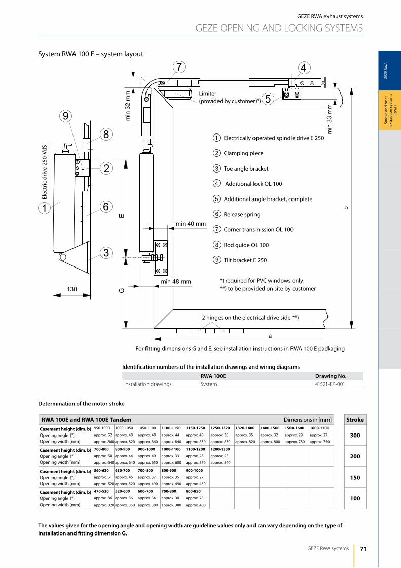
71
GEZ
E RW
A
GEZE RWA systems
Smok
e an
d he
at
extr
actio
n sy
stem
s (R
WA
)
System RWA 100 E – system layout
GEZE RWA exhaust systems
GEZE OPENiNG ANd lOCKiNG SySTEMS
Electrically operated spindle drive E 250
Clamping piece
Toe angle bracket
Additional lock Ol 100
Additional angle bracket, complete
Release spring
Corner transmission Ol 100
Rod guide Ol 100
Tilt bracket E 250
For fitting dimensions G and E, see installation instructions in RWA 100 E packaging
2 hinges on the electrical drive side **)
limiter (provided by customer)*)
Elec
tric
driv
e 25
0-Vd
S
*) required for PVC windows only**) to be provided on site by customer
The values given for the opening angle and opening width are guideline values only and can vary depending on the type of installation and fitting dimension G.
rwA 100e and rwA 100e tandem Dimensions in [mm] Strokecasement height (dim. b)Opening angle [°]Opening width [mm]
950-1000
approx. 52
approx. 860
1000-1050
approx. 48
approx. 820
1050-1100
approx. 48
approx. 860
1100-1150
approx. 44
approx. 840
1150-1250
approx. 40
approx. 830
1250-1320
approx. 38
approx. 850
1320-1400
approx. 35
approx. 820
1400-1500
approx. 32
approx. 800
1500-1600
approx. 29
approx. 780
1600-1700
approx. 27
approx. 750300
casement height (dim. b) Opening angle [°]Opening width [mm]
700-800
approx. 50
approx. 640
800-900
approx. 44
approx. 640
900-1000
approx. 40
approx. 650
1000-1100
approx. 33
approx. 600
1100-1200
approx. 28
approx. 570
1200-1300
approx. 25
approx. 540200
casement height (dim. b) Opening angle [°]Opening width [mm]
560-630
approx. 51
approx. 520
630-700
approx. 46
approx. 520
700-800
approx. 37
approx. 490
800-900
approx. 35
approx. 490
900-1000
approx. 27
approx. 450150
casement height (dim. b) Opening angle [°]Opening width [mm]
470-520
approx. 36
approx. 320
520-600
approx. 36
approx. 350
600-700
approx. 34
approx. 380
700-800
approx. 30
approx. 380
800-850
approx. 28
approx. 400100
Determination of the motor stroke
Identification numbers of the installation drawings and wiring diagrams
RWA 100E Drawing No.installation drawings System 41521-EP-001
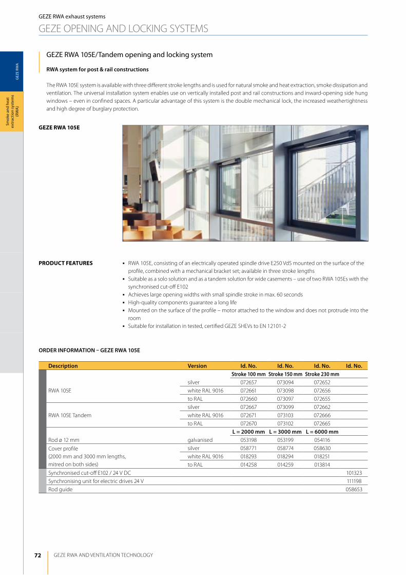
72
GEZ
E RW
A
geze rwA 105e
GEZE RWA ANd VENTilATiON TEChNOlOGy
Smok
e an
d he
at
extr
actio
n sy
stem
s (R
WA
)GEZE RWA exhaust systems
GEZE OPENiNG ANd lOCKiNG SySTEMS
GEZE RWA 105E/Tandem opening and locking system
RWA system for post & rail constructions
The RWA 105E system is available with three different stroke lengths and is used for natural smoke and heat extraction, smoke dissipation and ventilation. The universal installation system enables use on vertically installed post and rail constructions and inward-opening side hung windows – even in confined spaces. A particular advantage of this system is the double mechanical lock, the increased weathertightness and high degree of burglary protection.
j RWA 105E, consisting of an electrically operated spindle drive E250 VdS mounted on the surface of the profile, combined with a mechanical bracket set; available in three stroke lengths
j Suitable as a solo solution and as a tandem solution for wide casements – use of two RWA 105Es with the synchronised cut-off E102
j Achieves large opening widths with small spindle stroke in max. 60 secondsj high-quality components guarantee a long lifej Mounted on the surface of the profile – motor attached to the window and does not protrude into the
roomj Suitable for installation in tested, certified GEZE ShEVs to EN 12101-2
product FeAtureS
Description Version Id. No. Id. No. Id. No. Id. No.Stroke 100 mm Stroke 150 mm Stroke 230 mm
RWA 105E
silver 072657 073094 072652
white RAl 9016 072661 073098 072656
to RAl 072660 073097 072655
RWA 105E Tandem
silver 072667 073099 072662
white RAl 9016 072671 073103 072666
to RAl 072670 073102 072665
L = 2000 mm L = 3000 mm L = 6000 mmRod ø 12 mm galvanised 053198 053199 054116
Cover profile (2000 mm and 3000 mm lengths, mitred on both sides)
silver 058771 058774 058630
white RAl 9016 018293 018294 018251
to RAl 014258 014259 013814
Synchronised cut-off E102 / 24 V dC 101323
Synchronising unit for electric drives 24 V 111198
Rod guide 058653
ORDER INFORMATION – GEZE RWA 105E
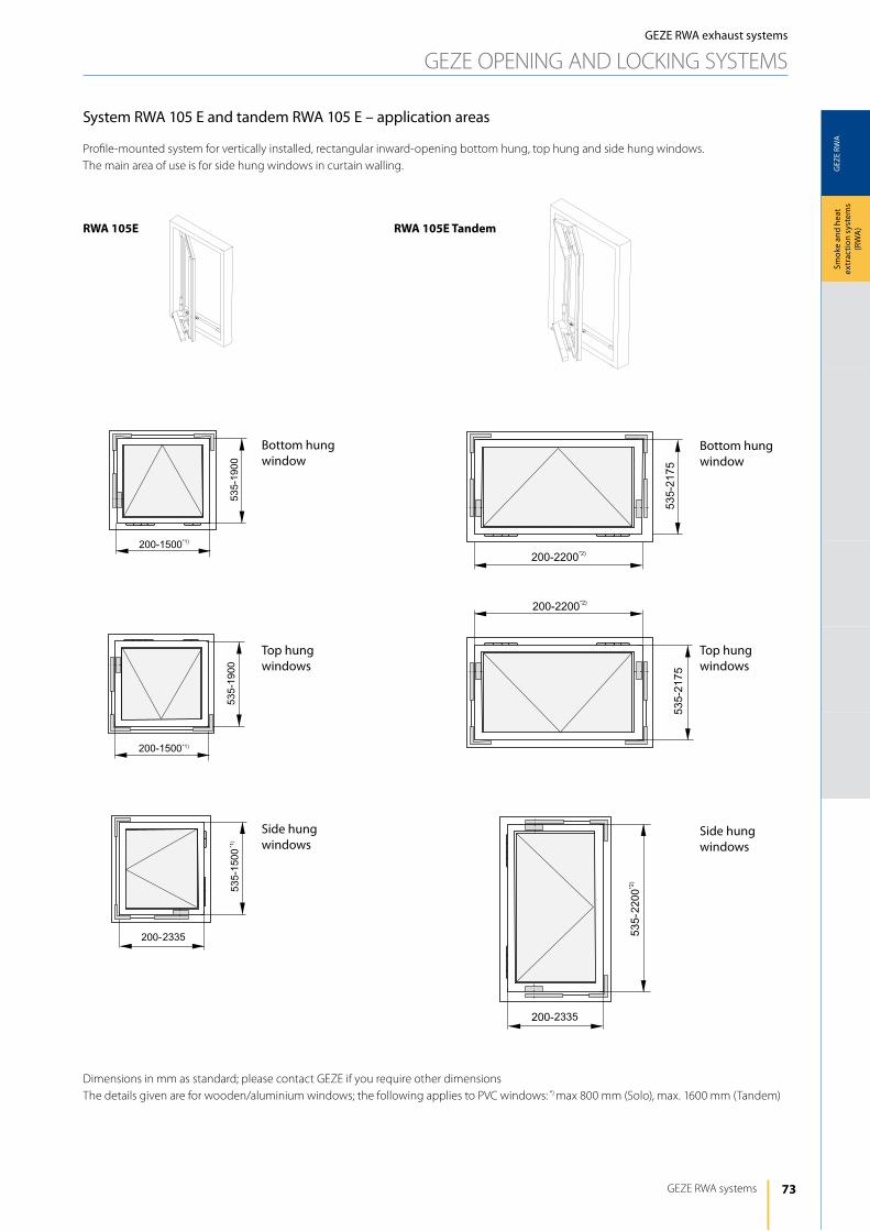
73
GEZ
E RW
A
GEZE RWA systems
Smok
e an
d he
at
extr
actio
n sy
stem
s (R
WA
)
GEZE RWA exhaust systems
GEZE OPENiNG ANd lOCKiNG SySTEMS
System RWA 105 E and tandem RWA 105 E – application areas
Profile-mounted system for vertically installed, rectangular inward-opening bottom hung, top hung and side hung windows. The main area of use is for side hung windows in curtain walling.
dimensions in mm as standard; please contact GEZE if you require other dimensionsThe details given are for wooden/aluminium windows; the following applies to PVC windows: *) max 800 mm (Solo), max. 1600 mm (Tandem)
rwA 105e rwA 105e tandem
Side hung windows
Bottom hung window
Top hung windows
Side hung windows
Bottom hung window
Top hung windows
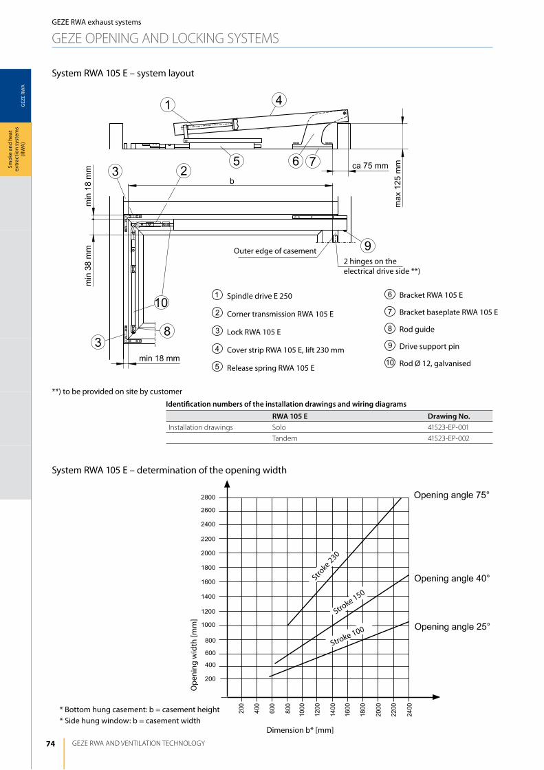
74
GEZ
E RW
A
400
600
800
1000
1600
1200
2000
1400
1800
200
2200
2400
2600
2800
200
600
800
1000
1200
1400400
1600
1800
2000
2200
2400
GEZE RWA ANd VENTilATiON TEChNOlOGy
Smok
e an
d he
at
extr
actio
n sy
stem
s (R
WA
)GEZE RWA exhaust systems
GEZE OPENiNG ANd lOCKiNG SySTEMS
System RWA 105 E – system layout
System RWA 105 E – determination of the opening width
Outer edge of casement2 hinges on the electrical drive side **)
**) to be provided on site by customer
Spindle drive E 250
Corner transmission RWA 105 E
lock RWA 105 E
Cover strip RWA 105 E, lift 230 mm
Release spring RWA 105 E
Bracket RWA 105 E
Bracket baseplate RWA 105 E
Rod guide
Drive support pin
Rod Ø 12, galvanised
Stroke 230
Ope
ning
wid
th [m
m]
Dimension b* [mm]
Stroke 150
Stroke 100
* Bottom hung casement: b = casement height* Side hung window: b = casement width
Opening angle 75°
Opening angle 40°
Opening angle 25°
Identification numbers of the installation drawings and wiring diagrams
RWA 105 E Drawing No.installation drawings Solo 41523-EP-001
Tandem 41523-EP-002
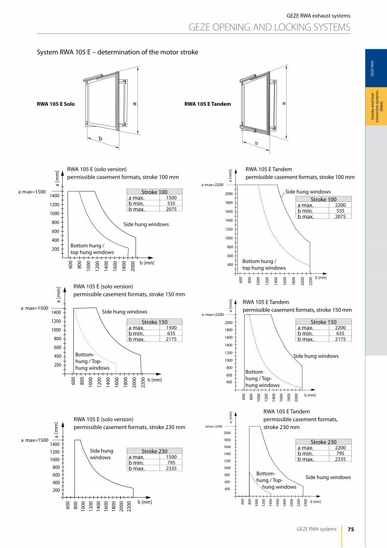
75
GEZ
E RW
A
ab
a
b
GEZE RWA systems
Smok
e an
d he
at
extr
actio
n sy
stem
s (R
WA
)
GEZE RWA exhaust systems
GEZE OPENiNG ANd lOCKiNG SySTEMS
RWA 105 E (solo version)permissible casement formats, stroke 100 mm
RWA 105 E Tandempermissible casement formats, stroke 100 mm
RWA 105 E (solo version)permissible casement formats, stroke 150 mm
RWA 105 E Tandempermissible casement formats, stroke 150 mm
RWA 105 E (solo version)permissible casement formats, stroke 230 mm
RWA 105 E Tandempermissible casement formats, stroke 230 mm
Side hung windows
Side hung windows
Side hung windows
Side hung windows
Side hung windows
Side hung windows
Bottom hung / top hung windows
Bottom hung / top hung windows
Bottom- hung / Top- hung windows
Bottom- hung / Top- hung windows
Bottom- hung / Top- hung windows
Stroke 100a max. 1500b min. 535b max. 2075
Stroke 150a max. 1500b min. 635b max. 2175
Stroke 230a max. 1500b min. 795b max. 2335
Stroke 100a max. 2200b min. 535b max. 2075
Stroke 150a max. 2200b min. 635b max. 2175
Stroke 230a max. 2200b min. 795b max. 2335
System RWA 105 E – determination of the motor stroke
rwA 105 e Solo rwA 105 e tandem
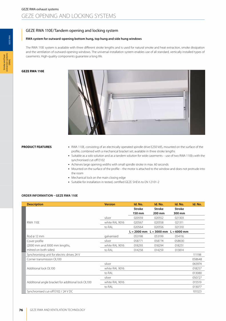
76
GEZ
E RW
A
geze rwA 110e
GEZE RWA ANd VENTilATiON TEChNOlOGy
Smok
e an
d he
at
extr
actio
n sy
stem
s (R
WA
)GEZE RWA exhaust systems
GEZE OPENiNG ANd lOCKiNG SySTEMS
GEZE RWA 110E/Tandem opening and locking system
RWA system for outward-opening bottom hung, top hung and side hung windows
The RWA 110E system is available with three different stroke lengths and is used for natural smoke and heat extraction, smoke dissipation and the ventilation of outward-opening windows. The universal installation system enables use of all standard, vertically installed types of casements. high-quality components guarantee a long life.
j RWA 110E, consisting of an electrically operated spindle drive E250 VdS, mounted on the surface of the profile, combined with a mechanical bracket set; available in three stroke lengths
j Suitable as a solo solution and as a tandem solution for wide casements – use of two RWA 110Es with the synchronised cut-off E102
j Achieves large opening widths with small spindle stroke in max. 60 secondsj Mounted on the surface of the profile – the motor is attached to the window and does not protrude into
the roomj Mechanical lock on the main closing edgej Suitable for installation in tested, certified GEZE ShEVs to EN 12101-2
product FeAtureS
Description Version Id. No. Id. No. Id. No. Id. No.Stroke
150 mmStroke
200 mmStroke
300 mm
RWA 110E
silver 020559 020552 021303
white RAl 9016 020567 020558 021311
to RAl 020564 020556 021310
L = 2000 mm L = 3000 mm L = 6000 mmRod ø 12 mm galvanised 053198 053199 054116
Cover profile (2000 mm and 3000 mm lengths, mitred on both sides)
silver 058771 058774 058630
white RAl 9016 018293 018294 018251
to RAl 014258 014259 013814
Synchronising unit for electric drives 24 V 111198
Corner transmission Ol100 058648
Additional lock Ol100
silver 063974
white RAl 9016 018257
to RAl 013080
Additional angle bracket for additional lock Ol100
silver 050727
white RAl 9016 015519
to RAl 013077
Synchronised cut-off E102 / 24 V dC 101323
ORDER INFORMATION – GEZE RWA 110E
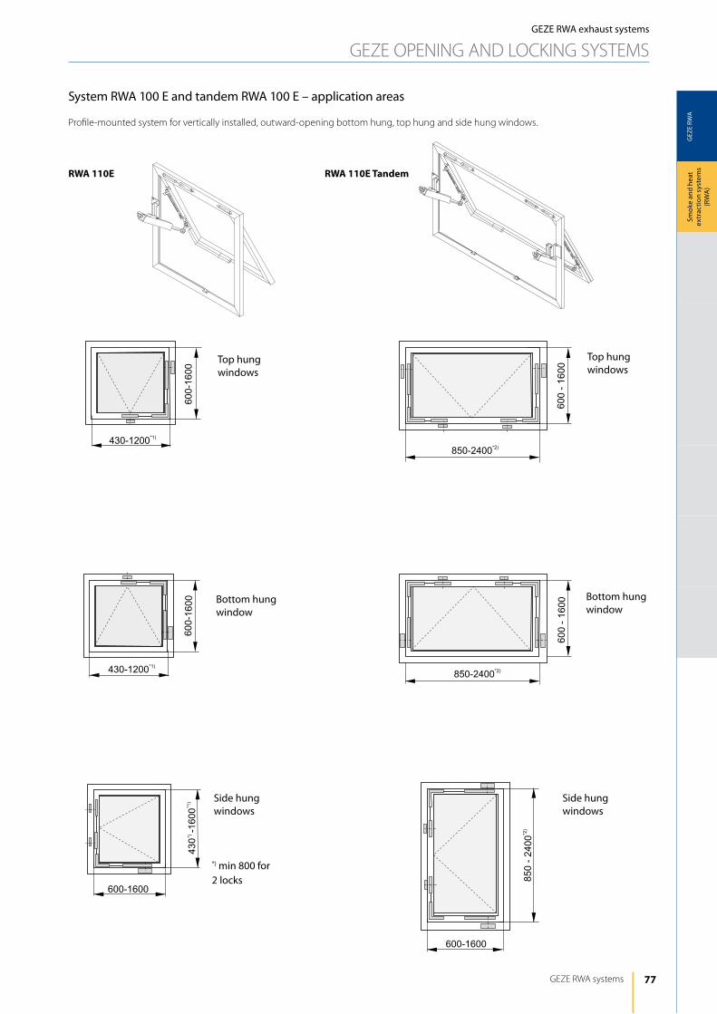
77
GEZ
E RW
A
GEZE RWA systems
Smok
e an
d he
at
extr
actio
n sy
stem
s (R
WA
)
GEZE RWA exhaust systems
GEZE OPENiNG ANd lOCKiNG SySTEMS
System RWA 100 E and tandem RWA 100 E – application areas
Profile-mounted system for vertically installed, outward-opening bottom hung, top hung and side hung windows.
rwA 110e rwA 110e tandem
Top hung windows
Bottom hung window
*) min 800 for 2 locks
Bottom hung window
Top hung windows
Side hung windows
Side hung windows
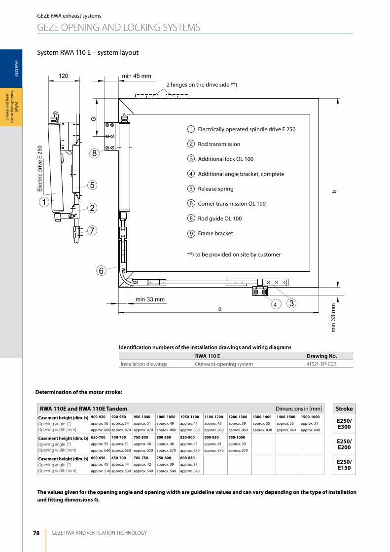
78
GEZ
E RW
A
6
4 3
G
5
2
7
b
a
8
1
120 min 45 mm
min
33m
m
min 33 mm
GEZE RWA ANd VENTilATiON TEChNOlOGy
Smok
e an
d he
at
extr
actio
n sy
stem
s (R
WA
)
System RWA 110 E – system layout
GEZE RWA exhaust systems
GEZE OPENiNG ANd lOCKiNG SySTEMS
Electrically operated spindle drive E 250
Rod transmission
Additional lock Ol 100
Additional angle bracket, complete
Release spring
Corner transmission Ol 100
Rod guide Ol 100
Frame bracket
2 hinges on the drive side **)
Elec
tric
driv
e E
250
**) to be provided on site by customer
determination of the motor stroke:
the values given for the opening angle and opening width are guideline values and can vary depending on the type of installation and fitting dimensions g.
rwA 110e and rwA 110e tandem Dimensions in [mm] Strokecasement height (dim. b)Opening angle [°]Opening width [mm]
900-920
approx. 56
approx. 880
920-950
approx. 54
approx. 870
950-1000
approx. 51
approx. 870
1000-1050
approx. 49
approx. 880
1050-1100
approx. 47
approx. 880
1100-1200
approx. 43
approx. 860
1200-1300
approx. 39
approx. 860
1300-1400
approx. 35
approx. 830
1400-1500
approx. 33
approx. 840
1500-1600
approx. 31
approx. 840
e250/e300
casement height (dim. b) Opening angle [°]Opening width [mm]
650-700
approx. 55
approx. 640
700-750
approx. 51
approx. 650
750-800
approx. 48
approx. 650
800-850
approx. 46
approx. 670
850-900
approx. 43
approx. 670
900-950
approx. 41
approx. 670
950-1000
approx. 39
approx. 670
e250/e200
casement height (dim. b) Opening angle [°]Opening width [mm]
600-650
approx. 45
approx. 510
650-700
approx. 44
approx. 530
700-750
approx. 42
approx. 540
750-800
approx. 39
approx. 540
800-850
approx. 37
approx. 540
e250/e150
Identification numbers of the installation drawings and wiring diagrams
RWA 110 E Drawing No.installation drawings Outward-opening system 41521-EP-002
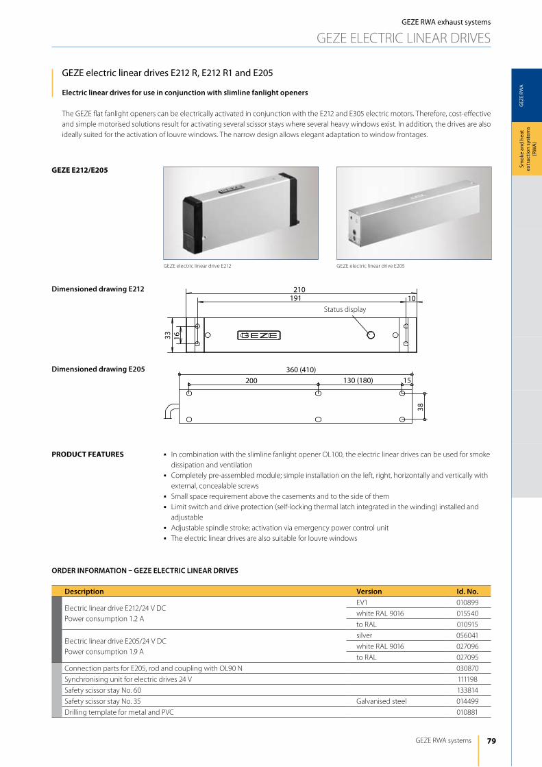
79
GEZ
E RW
A
geze e212/e205
210191 10
33 16
360 (410)200 130 (180) 15
38
GEZE RWA systems
Smok
e an
d he
at
extr
actio
n sy
stem
s (R
WA
)
GEZE RWA exhaust systems
GEZE ElECTRiC liNEAR dRiVES
GEZE electric linear drives E212 R, E212 R1 and E205
Electric linear drives for use in conjunction with slimline fanlight openers
The GEZE flat fanlight openers can be electrically activated in conjunction with the E212 and E305 electric motors. Therefore, cost-effective and simple motorised solutions result for activating several scissor stays where several heavy windows exist. in addition, the drives are also ideally suited for the activation of louvre windows. The narrow design allows elegant adaptation to window frontages.
j in combination with the slimline fanlight opener Ol100, the electric linear drives can be used for smoke dissipation and ventilation
j Completely pre-assembled module; simple installation on the left, right, horizontally and vertically with external, concealable screws
j Small space requirement above the casements and to the side of themj limit switch and drive protection (self-locking thermal latch integrated in the winding) installed and
adjustablej Adjustable spindle stroke; activation via emergency power control unitj The electric linear drives are also suitable for louvre windows
product FeAtureS
Description Version Id. No.
Electric linear drive E212/24 V dCPower consumption 1.2 A
EV1 010899
white RAl 9016 015540
to RAl 010915
Electric linear drive E205/24 V dCPower consumption 1.9 A
silver 056041
white RAl 9016 027096
to RAl 027095
Connection parts for E205, rod and coupling with Ol90 N 030870
Synchronising unit for electric drives 24 V 111198
Safety scissor stay No. 60 133814
Safety scissor stay No. 35 Galvanised steel 014499
drilling template for metal and PVC 010881
ORDER INFORMATION – GEZE ELECTRIC LINEAR DRIVES
GEZE electric linear drive E212 GEZE electric linear drive E205
Dimensioned drawing E212
Dimensioned drawing E205
Status display
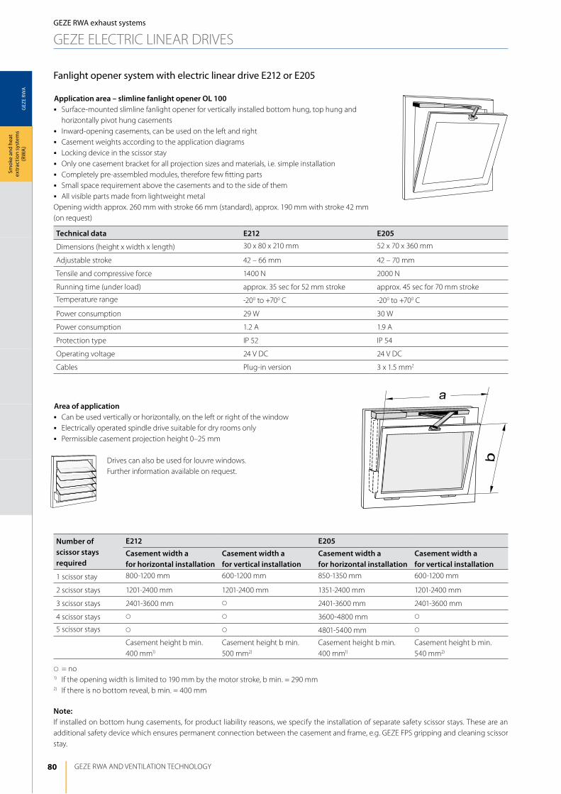
80
GEZ
E RW
A
GEZE RWA ANd VENTilATiON TEChNOlOGy
Smok
e an
d he
at
extr
actio
n sy
stem
s (R
WA
)GEZE RWA exhaust systems
GEZE ElECTRiC liNEAR dRiVES
Fanlight opener system with electric linear drive E212 or E205
Application area – slimline fanlight opener OL 100j Surface-mounted slimline fanlight opener for vertically installed bottom hung, top hung and
horizontally pivot hung casementsj inward-opening casements, can be used on the left and rightj Casement weights according to the application diagramsj locking device in the scissor stayj Only one casement bracket for all projection sizes and materials, i.e. simple installationj Completely pre-assembled modules, therefore few fitting partsj Small space requirement above the casements and to the side of themj All visible parts made from lightweight metalOpening width approx. 260 mm with stroke 66 mm (standard), approx. 190 mm with stroke 42 mm (on request)
Area of applicationj Can be used vertically or horizontally, on the left or right of the windowj Electrically operated spindle drive suitable for dry rooms onlyj Permissible casement projection height 0–25 mm
drives can also be used for louvre windows. Further information available on request.
Technical data E212 E205
dimensions (height x width x length) 30 x 80 x 210 mm 52 x 70 x 360 mm
Adjustable stroke 42 – 66 mm 42 – 70 mm
Tensile and compressive force 1400 N 2000 N
Running time (under load) approx. 35 sec for 52 mm stroke approx. 45 sec for 70 mm stroke
Temperature range -200 to +700 C -200 to +700 C
Power consumption 29 W 30 W
Power consumption 1.2 A 1.9 A
Protection type iP 52 iP 54
Operating voltage 24 V dC 24 V dC
Cables Plug-in version 3 x 1.5 mm2
Number of scissor stays required
E212 E205
Casement width a for horizontal installation
Casement width a for vertical installation
Casement width a for horizontal installation
Casement width a for vertical installation
1 scissor stay 800-1200 mm 600-1200 mm 850-1350 mm 600-1200 mm
2 scissor stays 1201-2400 mm 1201-2400 mm 1351-2400 mm 1201-2400 mm
3 scissor stays 2401-3600 mm s 2401-3600 mm 2401-3600 mm
4 scissor stays s s 3600-4800 mm s
5 scissor stays s s 4801-5400 mm s
Casement height b min. 400 mm1)
Casement height b min. 500 mm2)
Casement height b min. 400 mm1)
Casement height b min. 540 mm2)
s= no1) if the opening width is limited to 190 mm by the motor stroke, b min. = 290 mm2) if there is no bottom reveal, b min. = 400 mm
Note:if installed on bottom hung casements, for product liability reasons, we specify the installation of separate safety scissor stays. These are an additional safety device which ensures permanent connection between the casement and frame, e.g. GEZE FPS gripping and cleaning scissor stay.
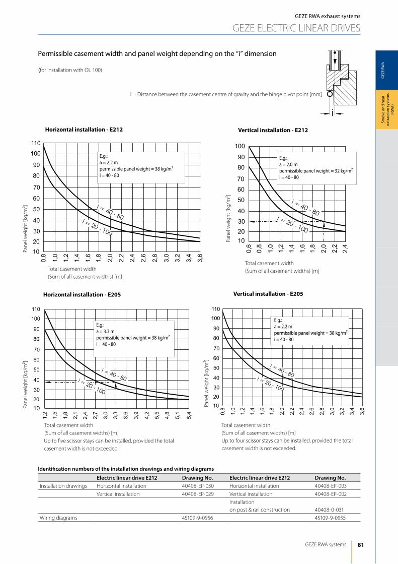
81
GEZ
E RW
A
i
GEZE RWA systems
Smok
e an
d he
at
extr
actio
n sy
stem
s (R
WA
)
GEZE RWA exhaust systems
GEZE ElECTRiC liNEAR dRiVES
Permissible casement width and panel weight depending on the “i” dimension
(for installation with Ol 100)
Up to four scissor stays can be installed, provided the total casement width is not exceeded.
horizontal installation - e205 Vertical installation - e205
Pane
l wei
ght [
kg/m
²]
Total casement width (Sum of all casement widths) [m]
E.g.:a = 2.0 mpermissible panel weight = 32 kg/m²i = 40 - 80
E.g.:a = 2.2 mpermissible panel weight = 38 kg/m²i = 40 - 80
Up to five scissor stays can be installed, provided the total casement width is not exceeded.
Pane
l wei
ght [
kg/m
²]
horizontal installation - e212 Vertical installation - e212
E.g.:a = 3.3 mpermissible panel weight = 38 kg/m²i = 40 - 80
E.g.:a = 2.2 mpermissible panel weight = 38 kg/m²i = 40 - 80
Total casement width (Sum of all casement widths) [m]
Pane
l wei
ght [
kg/m
²]
Pane
l wei
ght [
kg/m
²]
Total casement width (Sum of all casement widths) [m]
Total casement width (Sum of all casement widths) [m]
i = distance between the casement centre of gravity and the hinge pivot point [mm]
Identification numbers of the installation drawings and wiring diagrams
Electric linear drive E212 Drawing No. Electric linear drive E212 Drawing No.installation drawings horizontal installation 40408-EP-030 horizontal installation 40408-EP-003
Vertical installation 40408-EP-029 Vertical installation 40408-EP-002
installation on post & rail construction 40408-0-031
Wiring diagrams 45109-9-0956 45109-9-0955
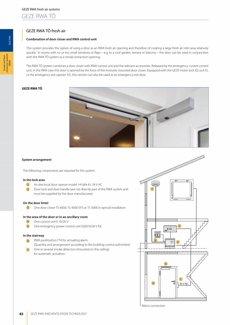
82
GEZ
E RW
A
geze rwA tÖ
1
4
56
7
3
6
GEZE RWA ANd VENTilATiON TEChNOlOGy
Smok
e an
d he
at
extr
actio
n sy
stem
s (R
WA
)GEZE RWA fresh air systems
GEZE RWA TÖ
GEZE RWA TÖ fresh air
Combination of door closer and RWA control unit
This system provides the option of using a door as an RWA fresh air opening and therefore of creating a large fresh air inlet area relatively quickly. in rooms with no or too small windows or flaps – e.g. to a roof garden, terrace or balcony – the door can be used in conjunction with the RWA TÖ system as a smoke extraction opening.
The RWA TÖ system combines a door closer with RWA control unit and the relevant accessories. Released by the emergency current control unit, in the RWA case this door is opened by the force of the inversely mounted door closer. Equipped with the GEZE motor lock iQ lock El or the emergency exit opener 331, this version can also be used as an emergency exit door.
Mains connection
1
3
4
5
6
7
2
System arrangement
The following components are required for this system:
In the lock areaAn electrical door opener model 14 Fafix Kl 24 V AC
door lock and door handle (are not directly part of the RWA system and must be supplied by the door manufacturer)
On the door lintelOne door closer TS 4000, TS 4000 EFS or TS 5000 in special installation
In the area of the door or in an ancillary roomOne control unit E 10/24 V
One emergency power control unit E260 N/24 V dC
In the stairwayRWA pushbutton FT4 for actuating alarm (Quantity and arrangement according to the building control authorities)
One or several smoke detectors (mounted on the ceiling) for automatic actuation
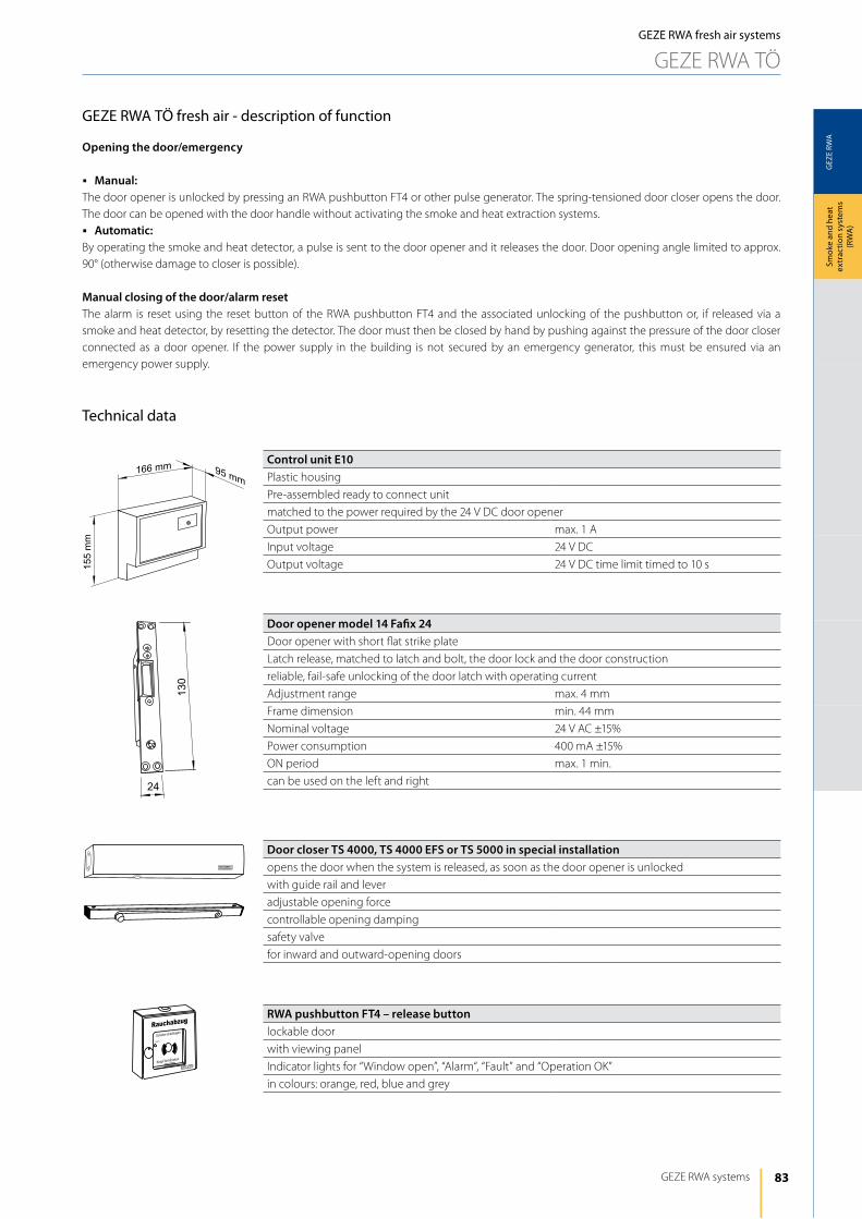
83
GEZ
E RW
A
166 mm 95 mm
155
mm
Rauchabzug
Scheibe einschlagen
Knopf tief drücken
Alarm
GEZE RWA systems
Smok
e an
d he
at
extr
actio
n sy
stem
s (R
WA
)
GEZE RWA fresh air systems
GEZE RWA TÖ
GEZE RWA TÖ fresh air - description of function
Opening the door/emergency
j Manual:The door opener is unlocked by pressing an RWA pushbutton FT4 or other pulse generator. The spring-tensioned door closer opens the door. The door can be opened with the door handle without activating the smoke and heat extraction systems.j Automatic:By operating the smoke and heat detector, a pulse is sent to the door opener and it releases the door. door opening angle limited to approx. 90° (otherwise damage to closer is possible).
Manual closing of the door/alarm resetThe alarm is reset using the reset button of the RWA pushbutton FT4 and the associated unlocking of the pushbutton or, if released via a smoke and heat detector, by resetting the detector. The door must then be closed by hand by pushing against the pressure of the door closer connected as a door opener. if the power supply in the building is not secured by an emergency generator, this must be ensured via an emergency power supply.
Technical data
Control unit E10Plastic housing
Pre-assembled ready to connect unit
matched to the power required by the 24 V dC door opener
Output power max. 1 A
input voltage 24 V dC
Output voltage 24 V dC time limit timed to 10 s
Door closer TS 4000, TS 4000 EFS or TS 5000 in special installationopens the door when the system is released, as soon as the door opener is unlocked
with guide rail and lever
adjustable opening force
controllable opening damping
safety valve
for inward and outward-opening doors
RWA pushbutton FT4 – release buttonlockable door
with viewing panel
indicator lights for “Window open”, “Alarm“, “Fault” and “Operation OK”
in colours: orange, red, blue and grey
Door opener model 14 Fafix 24door opener with short flat strike plate
latch release, matched to latch and bolt, the door lock and the door construction
reliable, fail-safe unlocking of the door latch with operating current
Adjustment range max. 4 mm
Frame dimension min. 44 mm
Nominal voltage 24 V AC ±15%
Power consumption 400 mA ±15%
ON period max. 1 min.
can be used on the left and right
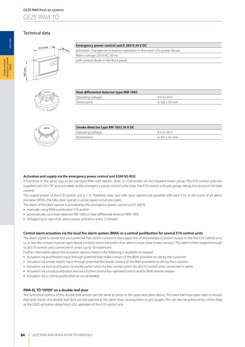
84
GEZ
E RW
A
213 mm 98 mm
180
mm
GEZE RWA ANd VENTilATiON TEChNOlOGy
Smok
e an
d he
at
extr
actio
n sy
stem
s (R
WA
)GEZE RWA fresh air systems
GEZE RWA TÖ
Technical data
Emergency power control unit E 260 N 24 V DCautomatic changeover to battery operation in the event of a power failure
Mains voltage 230 V AC, 50 hz
with control diode in the front panel
Heat differential detector type WM 1005Operating voltage: 8 V to 30 V
dimensions: ø 102 x 50 mm
Smoke detector type RM 1003 24 V DCOperating voltage: 8 V to 30 V
dimensions: ø 102 x 42 mm
Activation and supply via the emergency power control unit E260 N2-N32it functions in the same way as the standard RWA with electric drive, i.e. connection via the required motor group. The E10 control units are supplied with 24 V dC and activated via the emergency power control units (max. five E10 control units per group, taking into account the total current).The output power of the E10 control unit is 1 A. Therefore, max. two Fafix door openers are possible with each E10. in the event of an alarm (window OPEN), the Fafix door opener is active (open-circuit principle). The alarm of the door opener is actuated by the emergency power control unit E 260 Nj manually using RWA pushbutton FT4 and/orj automatically via smoke detector RM 1003 or heat differential detector WM 1005j retriggering in case of an alarm causes activation every 2 minutes
Central alarm actuation via the local fire alarm system (BMA) or a central pushbutton for several E10 control unitsThe alarm signal is connected via a potential-free switch contact to the supply line of the emergency power supply to the first E10 control unit, i.e. at rest the contact must be open (break contact) and in the event of an alarm it must close (make contact). The alarm is then looped through to all E10 control units connected in series (up to 10 maximum).Further information about the actuation options listed in the following is available on request:j Actuation via pushbutton input through potential-free make contact of the BMA provided on site by the customerj Actuation via smoke switch input through potential-free break contact of the BMA provided on site by the customerj Actuation via local pushbutton or smoke switch and a further central switch for all E10 control units connected in seriesj Actuation via a local pushbutton and via a further central key-operated switch and/or BMA remote releasej Actuation via a central pushbutton as circuit-breaker
RWA-EL TÖ “OPEN” on a double-leaf doorThe functional options of the double-leaf version are the same as those in the cases described above. The fixed leaf must open later to ensure that both leaves of a double-leaf door are not opened at the same time, causing them to get caught. This can also be achieved by a time relay or the GEZE activation delay block lEV, upstream of the E10 control unit.
85
GEZ
E RW
A
GEZE RWA systems
Smok
e an
d he
at
extr
actio
n sy
stem
s (R
WA
)
GEZE RWA fresh air systems
GEZE RWA TÖ
Combination with the GEZE escape route system (RWS)The function is similar to that of the standard version. An inverse type door closer (with preloaded spring) and an electrical retention magnet (MA 500 with reed contact) is installed on the door. The retention magnet is continuously supplied with current and keeps the door closed against the spring force of the door closer (closed-circuit principle).The retention magnet is activated and supplied via an RWS door control unit. in a panic case, the door control unit is released directly by pressing the emergency button. The door control unit is connected to an RWA E 260 N emergency power control unit (relay alarm) via a potential-free break contact. in the case of a fire, the alarm is actuated and the magnet is released by pressing an RWA pushbutton (manual release) or smoke switch (automatic release). The door is then opened by the spring force of the door closer.in this system, the door control unit can also be unlocked and the door passed through using a key-operated switch. After passing through the door it must be re-closed manually, against the spring force of the door closer.in the event of short-term release, automatic locking is possible after closing the door (a so-called discontinuation), i.e. the door only has to be pressed shut and locks automatically, as soon as the door leaf is closed.
Note: For further information on the RWS function and the door control units, please refer to the GEZE Seculogic documents.
Combination with TS 4000 EFS(invers version/for convenient passing through the door in normal operation)The Freeswing door closer TS 4000 EFS (in special installation for the RWA-El-TÖ “OPEN” system) in inverse activation enables the user to conveniently pass through the door in routine operation.in case of fire the door opens automatically (by manual or automatic activation), to ensure smoke extraction.
Manual:j Emergency: The door opener is unlocked by pressing a pushbutton or other pulse generator. The spring-tensioned door closer opens the
door (Freeswing function is deactivated).j Normal operation: The door can be opened with the door handle.
Automatic:j By operating the smoke and heat detector, a pulse is sent to the door opener and it releases the door; the door opens (Freeswing function is
deactivated).
Closing the door:j Following emergency: The pressed button and/or smoke and heat switches must be reset. The door must then be closed by hand by
pushing against the pressure of the door closer connected as a “door opener”.
Note: Combination with the GEZE MlS motor lock is possible. Please contact GEZE Gmbh for details.
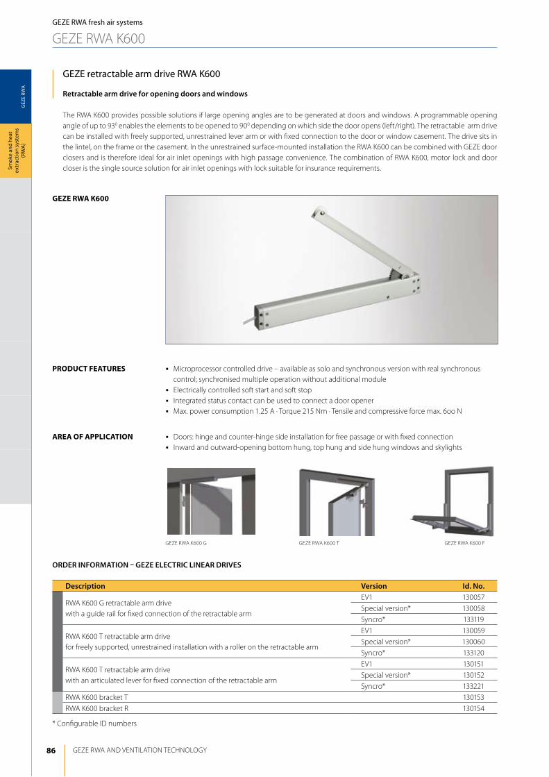
86
GEZ
E RW
A
geze rwA K600
GEZE RWA ANd VENTilATiON TEChNOlOGy
Smok
e an
d he
at
extr
actio
n sy
stem
s (R
WA
)
GEZE RWA K600 FGEZE RWA K600 G GEZE RWA K600 T
GEZE RWA fresh air systems
GEZE RWA K600
GEZE retractable arm drive RWA K600
Retractable arm drive for opening doors and windows
The RWA K600 provides possible solutions if large opening angles are to be generated at doors and windows. A programmable opening angle of up to 930 enables the elements to be opened to 900 depending on which side the door opens (left/right). The retractable arm drive can be installed with freely supported, unrestrained lever arm or with fixed connection to the door or window casement. The drive sits in the lintel, on the frame or the casement. in the unrestrained surface-mounted installation the RWA K600 can be combined with GEZE door closers and is therefore ideal for air inlet openings with high passage convenience. The combination of RWA K600, motor lock and door closer is the single source solution for air inlet openings with lock suitable for insurance requirements.
AreA oF ApplicAtion j doors: hinge and counter-hinge side installation for free passage or with fixed connectionj inward and outward-opening bottom hung, top hung and side hung windows and skylights
Description Version Id. No.
RWA K600 G retractable arm drive with a guide rail for fixed connection of the retractable arm
EV1 130057
Special version* 130058
Syncro* 133119
RWA K600 T retractable arm drive for freely supported, unrestrained installation with a roller on the retractable arm
EV1 130059
Special version* 130060
Syncro* 133120
RWA K600 T retractable arm drive with an articulated lever for fixed connection of the retractable arm
EV1 130151
Special version* 130152
Syncro* 133221
RWA K600 bracket T 130153
RWA K600 bracket R 130154
* Configurable id numbers
ORDER INFORMATION – GEZE ELECTRIC LINEAR DRIVES
j Microprocessor controlled drive – available as solo and synchronous version with real synchronous control; synchronised multiple operation without additional module
j Electrically controlled soft start and soft stopj integrated status contact can be used to connect a door openerj Max. power consumption 1.25 A · Torque 215 Nm · Tensile and compressive force max. 6oo N
product FeAtureS
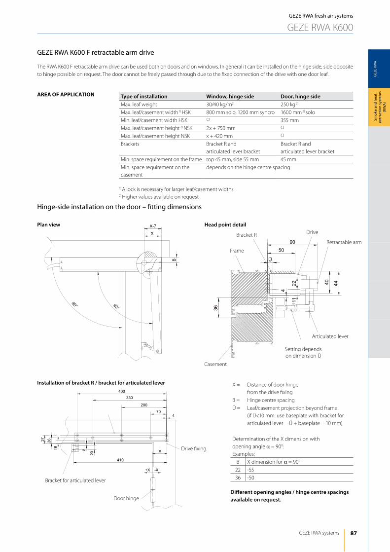
87
GEZ
E RW
A
X
B
93°
90°
X-7
90
50
Ü
40 442 211
4
36
GEZE RWA systems
Smok
e an
d he
at
extr
actio
n sy
stem
s (R
WA
)
GEZE RWA fresh air systems
GEZE RWA K600
AreA oF ApplicAtion
GEZE RWA K600 F retractable arm drive
The RWA K600 F retractable arm drive can be used both on doors and on windows. in general it can be installed on the hinge side, side opposite to hinge possible on request. The door cannot be freely passed through due to the fixed connection of the drive with one door leaf.
Hinge-side installation on the door – fitting dimensions
Type of installation Window, hinge side Door, hinge sideMax. leaf weight 30/40 kg/m2 250 kg 2)
Max. leaf/casement width 1) hSK 800 mm solo, 1200 mm syncro 1600 mm 2) solo
Min. leaf/casement width hSK s 355 mm
Max. leaf/casement height 2) NSK 2x + 750 mm s
Max. leaf/casement height NSK x + 420 mm s
Brackets Bracket R and articulated lever bracket
Bracket R and articulated lever bracket
Min. space requirement on the frame top 45 mm, side 55 mm 45 mm
Min. space requirement on the casement
depends on the hinge centre spacing
1) A lock is necessary for larger leaf/casement widths2) higher values available on request
Plan view Head point detail
Installation of bracket R / bracket for articulated lever
Bracket for articulated lever
door hinge
drive fixing
Bracket R drive
Frame
Retractable arm
Casement
Setting depends on dimension Ü
Articulated lever
X = distance of door hingefrom the drive fixing
B = hinge centre spacing
Ü = leaf/casement projection beyond frame (if Ü<10 mm: use baseplate with bracket for articulated lever = Ü + baseplate = 10 mm)
determination of the X dimension with opening angle a = 900:Examples:
B X dimension for a = 900
22 -55
36 -50
Different opening angles / hinge centre spacings available on request.
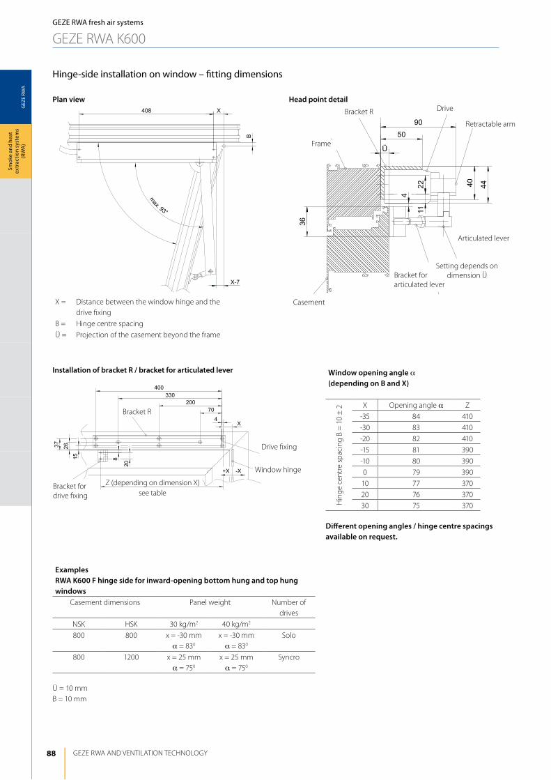
88
GEZ
E RW
A
408 X
B
max. 93°
X-7
90
50
Ü
40 442 211
4
36
GEZE RWA ANd VENTilATiON TEChNOlOGy
Smok
e an
d he
at
extr
actio
n sy
stem
s (R
WA
)
Hinge-side installation on window – fitting dimensions
Plan view Head point detail
Installation of bracket R / bracket for articulated lever
Bracket for drive fixing
Window hinge
drive fixing
Frame
Setting depends on dimension Ü
Window opening angle a (depending on B and X)
hin
ge c
entr
e sp
acin
g B
= 1
0 ±
2 X Opening angle a Z
-35 84 410
-30 83 410
-20 82 410
-15 81 390
-10 80 390
0 79 390
10 77 370
20 76 370
30 75 370
Different opening angles / hinge centre spacings available on request.
GEZE RWA fresh air systems
GEZE RWA K600
X = distance between the window hinge and the drive fixing
B = hinge centre spacing
Ü = Projection of the casement beyond the frame
Bracket R
Casement
Articulated lever
Bracket for articulated lever
drive
Retractable arm
Bracket R
Z (depending on dimension X)see table
Examples RWA K600 F hinge side for inward-opening bottom hung and top hung windows
Casement dimensions Panel weight Number of drives
NSK hSK 30 kg/m2 40 kg/m2
800 800 x = -30 mma = 830
x = -30 mma = 830
Solo
800 1200 x = 25 mma = 750
x = 25 mma = 750
Syncro
Ü = 10 mmB = 10 mm
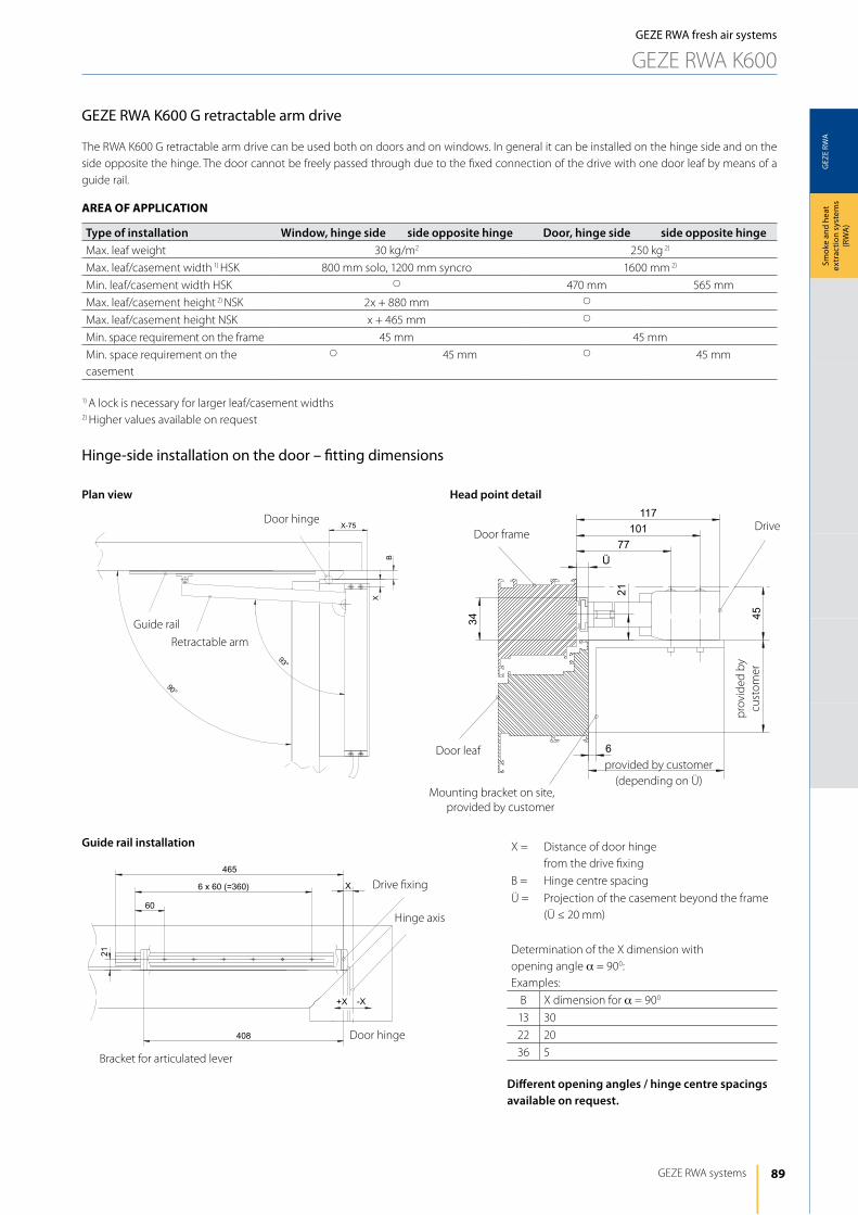
89
GEZ
E RW
A
90°
93°
B
X
X-75
465
6 x 60 (=360)
60
X
408
21
-X+X
117
21
6
77
101
Ü
34 45
GEZE RWA systems
Smok
e an
d he
at
extr
actio
n sy
stem
s (R
WA
)
GEZE RWA fresh air systems
GEZE RWA K600
AreA oF ApplicAtion
GEZE RWA K600 G retractable arm drive
The RWA K600 G retractable arm drive can be used both on doors and on windows. in general it can be installed on the hinge side and on the side opposite the hinge. The door cannot be freely passed through due to the fixed connection of the drive with one door leaf by means of a guide rail.
Hinge-side installation on the door – fitting dimensions
Type of installation Window, hinge side side opposite hinge Door, hinge side side opposite hingeMax. leaf weight 30 kg/m2 250 kg 2)
Max. leaf/casement width 1) hSK 800 mm solo, 1200 mm syncro 1600 mm 2)
Min. leaf/casement width hSK s 470 mm 565 mm
Max. leaf/casement height 2) NSK 2x + 880 mm s
Max. leaf/casement height NSK x + 465 mm s
Min. space requirement on the frame 45 mm 45 mm
Min. space requirement on the casement
s 45 mm s 45 mm
1) A lock is necessary for larger leaf/casement widths2) higher values available on request
Plan view Head point detail
Guide rail installation
Bracket for articulated lever
door hinge
drive fixing
drivedoor frame
provided by customer(depending on Ü)
X = distance of door hingefrom the drive fixing
B = hinge centre spacing
Ü = Projection of the casement beyond the frame(Ü ≤ 20 mm)
determination of the X dimension with opening angle a = 900:Examples:
B X dimension for a = 900
13 30
22 20
36 5
Different opening angles / hinge centre spacings available on request.
door hinge
Guide rail
Retractable arm
hinge axis
door leaf
Mounting bracket on site, provided by customer
prov
ided
by
cust
omer
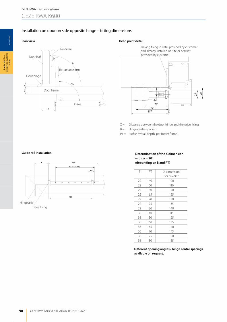
90
GEZ
E RW
A
X 465
6 x 60 (=360)
60
408
GEZE RWA ANd VENTilATiON TEChNOlOGy
Smok
e an
d he
at
extr
actio
n sy
stem
s (R
WA
)
Installation on door on side opposite hinge – fitting dimensions
Plan view Head point detail
Guide rail installation
driving fixing in lintel provided by customer and already installed on site or bracket provided by customer
Determination of the X dimension with a = 900
(depending on B and PT)
B PT X dimension for a = 900
22 40 100
22 50 110
22 60 120
22 65 125
22 70 130
22 75 135
22 80 140
36 40 115
36 50 125
36 60 135
36 65 140
36 70 145
36 75 150
36 80 155
Different opening angles / hinge centre spacings available on request.
X = distance between the door hinge and the drive fixing
B = hinge centre spacing
PT = Profile overall depth, perimeter frame
hinge axis
GEZE RWA fresh air systems
GEZE RWA K600
Guide rail
Retractable arm
drive
door frame
door hinge
door leaf
drive fixing

91
GEZ
E RW
A
B
max. 93°
X
�
X-75
117
101
77
min. 2
21
6
4034
465
450
6 x 60 (=360)
X
60
408
21
-X+X
GEZE RWA systems
Smok
e an
d he
at
extr
actio
n sy
stem
s (R
WA
)
Hinge-side installation on window – fitting dimensions
Plan view Head point detail
Guide rail installation Window opening angle a = 900
(depending on B and X)
X B Opening angle a
30 10 900
60 10 850
90 10 800
120 10 750
150 10 710
190 10 650
230 10 600
Different opening angles / hinge centre spacings available on request.
X = distance between the window hinge and the drive fixing
B = hinge centre spacing
PT = Profile overall depth, perimeter frame
hinge axis
GEZE RWA fresh air systems
GEZE RWA K600
Guide rail
Retractable arm
drive
Mounting bracket on site, provided by customer
Frame
Casement
drive fixing
provided by customer
Examples RWA K600 G hinge side for inward-opening bottom hung and top hung windows
Casement dimensions Panel weight Number of drives
NSK hSK 30 kg/m2 40 kg/m2
800 800 x = 30 mma = 900
x = 30 mma = 900
Solo
800 1200 x = 30 mma = 900
x = 30 mma = 900
Syncro
1200 1200 x = 160 mma = 700
x = 160 mma = 700
Syncro
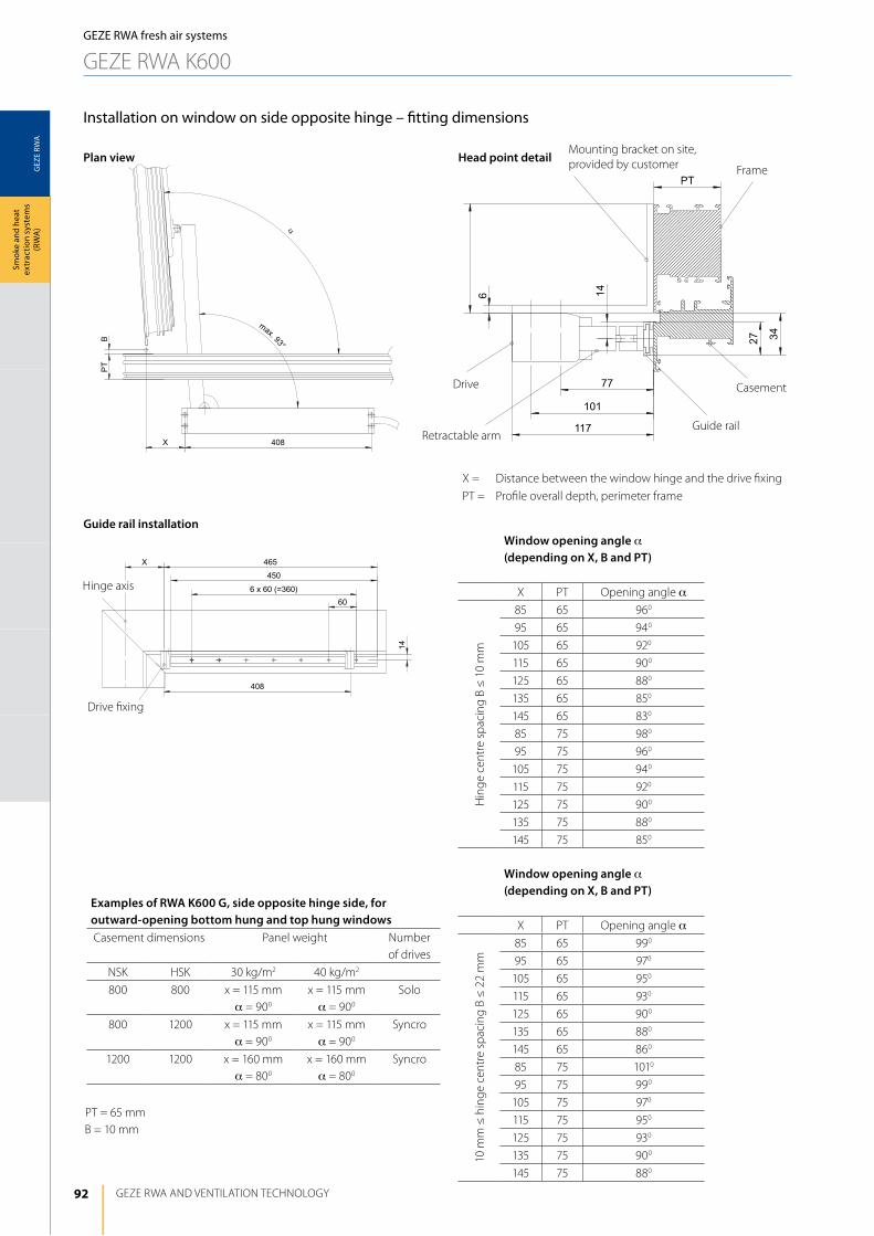
92
GEZ
E RW
A
1 4
408
60
6 x 60 (=360)
450
465X
GEZE RWA ANd VENTilATiON TEChNOlOGy
Smok
e an
d he
at
extr
actio
n sy
stem
s (R
WA
)
Installation on window on side opposite hinge – fitting dimensions
Plan view Head point detail
Guide rail installationWindow opening angle a(depending on X, B and PT)
X PT Opening angle a
hin
ge c
entr
e sp
acin
g B
≤ 1
0 m
m
85 65 960
95 65 940
105 65 920
115 65 900
125 65 880
135 65 850
145 65 830
85 75 980
95 75 960
105 75 940
115 75 920
125 75 900
135 75 880
145 75 850
Window opening angle a(depending on X, B and PT)
X PT Opening angle a
10 m
m ≤
hin
ge c
entr
e sp
acin
g B
≤ 2
2 m
m
85 65 990
95 65 970
105 65 950
115 65 930
125 65 900
135 65 880
145 65 860
85 75 1010
95 75 990
105 75 970
115 75 950
125 75 930
135 75 900
145 75 880
X = distance between the window hinge and the drive fixing
PT = Profile overall depth, perimeter frame
hinge axis
Guide railRetractable arm
drive
Mounting bracket on site, provided by customer Frame
Casement
drive fixing
GEZE RWA fresh air systems
GEZE RWA K600
Examples of RWA K600 G, side opposite hinge side, for outward-opening bottom hung and top hung windowsCasement dimensions Panel weight Number
of drives
NSK hSK 30 kg/m2 40 kg/m2
800 800 x = 115 mma = 900
x = 115 mma = 900
Solo
800 1200 x = 115 mma = 900
x = 115 mma = 900
Syncro
1200 1200 x = 160 mma = 800
x = 160 mma = 800
Syncro
PT = 65 mmB = 10 mm
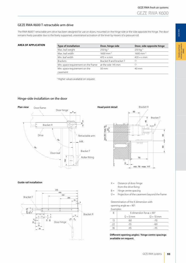
93
GEZ
E RW
A
X
B
93°
90°
100
X-22
470
400
330
200
704
X
42
92
70
30
8
max.70
1 122
1 4
-X+X
2 2
min.55/ma x.70
50
40
5050
75
min. 78 - max. 117
Ü
2
GEZE RWA systems
Smok
e an
d he
at
extr
actio
n sy
stem
s (R
WA
)
GEZE RWA fresh air systems
GEZE RWA K600
GEZE RWA K600 T retractable arm drive
The RWA K600 T retractable arm drive has been designed for use on doors, mounted on the hinge side or the side opposite the hinge. The door remains freely passable due to the freely supported, unrestrained activation of the lever by means of a pressure roll.
Hinge-side installation on the door
Plan view Head point detail
Guide rail installation
Bracket T
door hinge
X = distance of door hinge from the drive fixing
B = hinge centre spacing
Ü = Projection of the casement beyond the frame
determination of the X dimension with opening angle a = 900:Examples:
B X dimension for a = 900
Ü = 0 mm Ü = 10 mm
13 -60 -70
22 -55 -60
36 -45 -45
Different opening angles / hinge centre spacings available on request.
door hingedoor frame
Retractable arm
AreA oF ApplicAtion Type of installation Door, hinge side Door, side opposite hingeMax. leaf weight 250 kg 1) 250 kg 1)
Max. leaf width 1600 mm 1) 1600 mm 1)
Min. leaf width 470 + x mm 420 + x mm
Brackets Bracket R and bracket T s
Min. space requirement on the frame at the side 145 mm s
Min. space requirement on the casement
50 mm 40 mm
1) higher values available on request
Bracket R
Bracket R
Bracket T
drive
door leafBracket T
Roller fitting
Bracket R
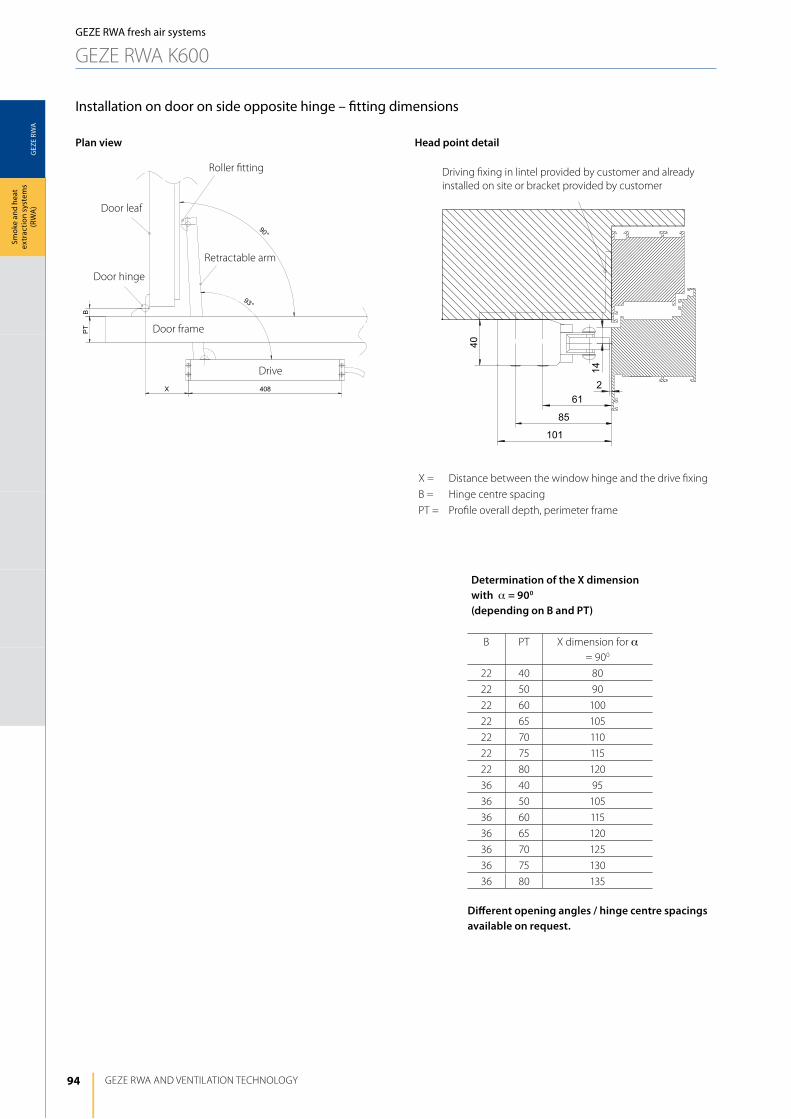
94
GEZ
E RW
A
GEZE RWA ANd VENTilATiON TEChNOlOGy
Smok
e an
d he
at
extr
actio
n sy
stem
s (R
WA
)
Installation on door on side opposite hinge – fitting dimensions
Plan view Head point detail
driving fixing in lintel provided by customer and already installed on site or bracket provided by customer
Determination of the X dimension with a = 900
(depending on B and PT)
B PT X dimension for a = 900
22 40 80
22 50 90
22 60 100
22 65 105
22 70 110
22 75 115
22 80 120
36 40 95
36 50 105
36 60 115
36 65 120
36 70 125
36 75 130
36 80 135
Different opening angles / hinge centre spacings available on request.
X = distance between the window hinge and the drive fixing
B = hinge centre spacing
PT = Profile overall depth, perimeter frame
Roller fitting
Retractable arm
drive
door frame
door hinge
door leaf
GEZE RWA fresh air systems
GEZE RWA K600
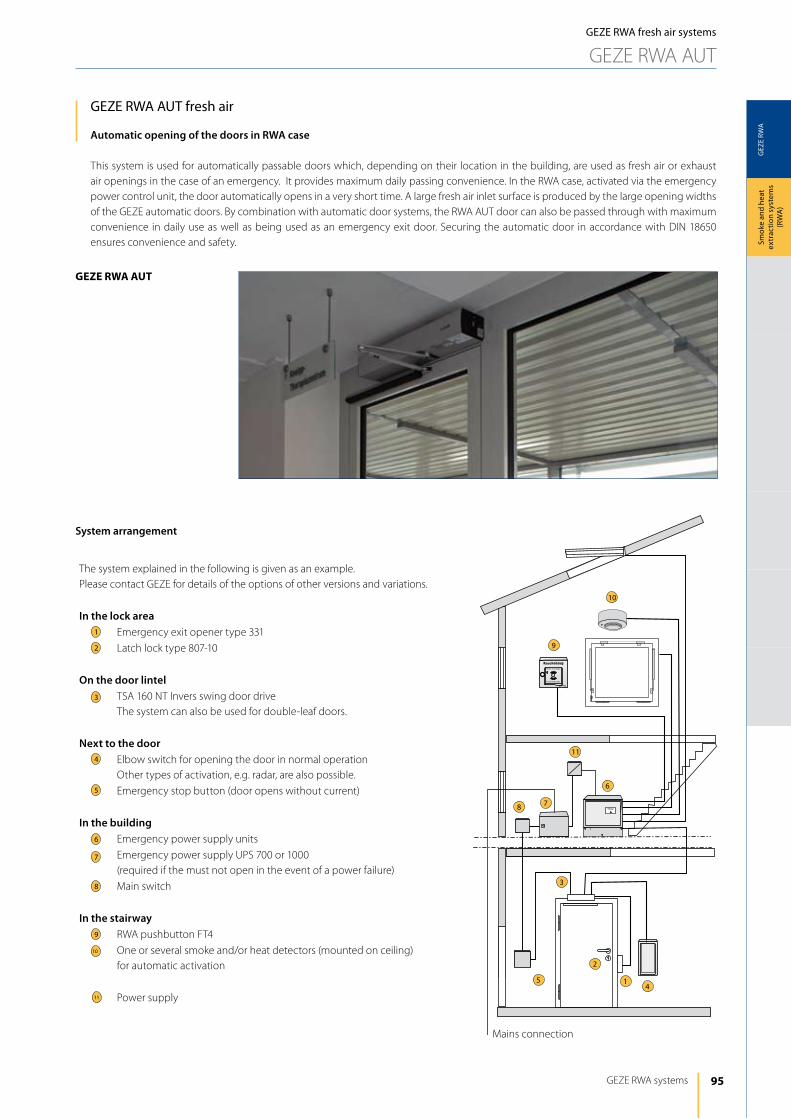
95
GEZ
E RW
A
1
2
3
6
8
9
4
7
5
10
11
GEZE RWA systems
Smok
e an
d he
at
extr
actio
n sy
stem
s (R
WA
)
geze rwA Aut
GEZE RWA fresh air systems
GEZE RWA AUT
GEZE RWA AuT fresh air
Automatic opening of the doors in RWA case
This system is used for automatically passable doors which, depending on their location in the building, are used as fresh air or exhaust air openings in the case of an emergency. it provides maximum daily passing convenience. in the RWA case, activated via the emergency power control unit, the door automatically opens in a very short time. A large fresh air inlet surface is produced by the large opening widths of the GEZE automatic doors. By combination with automatic door systems, the RWA AUT door can also be passed through with maximum convenience in daily use as well as being used as an emergency exit door. Securing the automatic door in accordance with diN 18650 ensures convenience and safety.
Mains connection
System arrangement
The system explained in the following is given as an example. Please contact GEZE for details of the options of other versions and variations.
In the lock areaEmergency exit opener type 331
latch lock type 807-10
On the door lintelTSA 160 NT invers swing door driveThe system can also be used for double-leaf doors.
Next to the doorElbow switch for opening the door in normal operationOther types of activation, e.g. radar, are also possible.
Emergency stop button (door opens without current)
In the buildingEmergency power supply units
Emergency power supply UPS 700 or 1000(required if the must not open in the event of a power failure)
Main switch
In the stairwayRWA pushbutton FT4
One or several smoke and/or heat detectors (mounted on ceiling) for automatic activation
Power supply
1
3
4
5
6
7
8
9
10
11
2
96
GEZ
E RW
A
GEZE RWA ANd VENTilATiON TEChNOlOGy
Smok
e an
d he
at
extr
actio
n sy
stem
s (R
WA
)GEZE RWA fresh air systems
GEZE RWA AUT
GEZE RWA AuT fresh air - functional description
Function description with FTÖ 331Compared to swing door drive TSA 160 NT, which opens the door automatically and closes by spring force, the TSA 160 NT invers drive inverts this function. in this case the closing action is automated, the opening takes place mechanically by means of spring force (advantage in RWA case). i.e. the TSA 160 NT invers opens by means of spring force in case of fire or in the event of a power failure – closed-circuit principle. it is therefore also necessary to use no-load door openers (or retention magnets); electric strike fail secure openers would not release the door in the door in the event of a power failure. An uninterruptible power supply (UPS) is required to prevent unwanted opening of the door in the event of a power failure (e.g. at night).
Opening the door in case of emergencyin the event of a fire button or smoke detector alarm the power supply to the drive and to the door opener is interrupted. The doors are immediately unlocked and mechanically opened to ensure reliable smoke removal. The doors remain open until the alarm is reset.
Opening the door in normal operationThe door opener is unlocked by pressing an elbow switch or other pulse generator. The spring-tensioned swing door drive opens the door mechanically by means of spring force.
Closing the door in normal operationin normal operation the door automatically closes via the control of the swing door drive after the set hold open time has expired.
Supply to the shut-down indicator boardThe shut-down indicator board of the TSA 160 NT invers must be supplied with an additional power supply.
Manual passing through the doorA door equipped with the TSA 160 NT invers cannot be simply passed through manually. The door kept closed, not only by the emergency exit opener but also by the solenoid valve of the hydraulics. As manual passing through the door does not generate an activation signal, when the door is manually opened the drive attempts to close it again – this is comparable to the permanently open position of the (standard) TSA 160 NT, from which it cannot be closed manually.
Emergency power supply UPSif the door must not open in the event of a power failure, the invers must also be equipped with a UPS in addition to the additional power supply required.
Note: Version with automatic swing door drive in accordance with diN 18650.
Combination of TSA 160 NT Invers with motor lock IQ Lock ELThe TSA 160 NT invers can be combined with the GEZE motor lock. As the lock operates according to the open-circuit principle, in the RWA case it is necessary to ensure that the lock is supplied with 24 V, e.g. by a GEZE RWA control unit E260N... Use of the GEZE motor lock iQ lock El is only possible on 1 leaf doors. The MST212 circuit board is also required for the RWA fresh air function; in the RWA case the board forwards the activation of the RWA control unit to the lock and simultaneously switches off the TSA 160 NT invers.
Opening the door in case of emergency:The additional MST212 circuit board is activated, e.g. by the E260N. On the one hand, the MST212 supplies the motor lock with voltage, on the other hand it activates the lock, which means the lock is reliably unlocked, i.e. even in the event of a power failure. The power supply at the TSA160NT invers drive is interrupted by a contact in the MST212. As soon as the lock has been unlocked the doors are opened by the spring force of the drive.
Closing the door after an alarm:After cancelling the alarm, activated RWA pushbuttons and / or the smoke and heat differential detectors must be reset. if the door is closed, it is automatically locked again via the motor lock or switches to the operating mode set at the lock. The door is therefore locked again. After the alarm, the lock locks in precisely the same operating setting as the one set before the alarm (night / day / continuously open). The TSA 160 NT inver must be reset.
Opening the door in normal operation:The GEZE iQ lock El is unlocked by pressing an elbow switch or other pulse generator. The spring-tensioned swing door drive opens the door mechanically by means of spring force.
Closing the door in normal operation:in normal operation the door automatically closes via the control of the swing door drive after the set hold open time has expired. The shut-down indicator board is supplied via the power supply of the MST 212.
Manual passing through the doorManual passing through the door is possible by pressing the internal door handle or by means of a key and a cylinder lock.
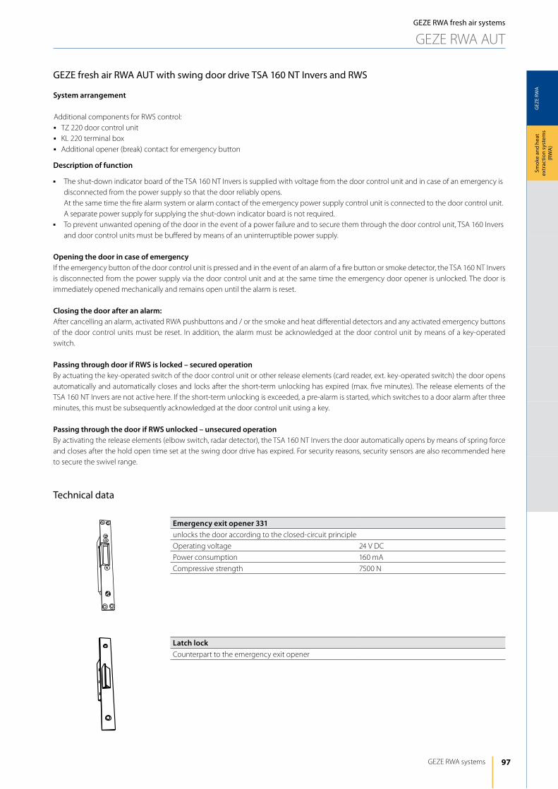
97
GEZ
E RW
A
GEZE RWA systems
Smok
e an
d he
at
extr
actio
n sy
stem
s (R
WA
)
GEZE RWA fresh air systems
GEZE RWA AUT
GEZE fresh air RWA AuT with swing door drive TSA 160 NT Invers and RWS
System arrangement
Additional components for RWS control:j TZ 220 door control unitj Kl 220 terminal boxj Additional opener (break) contact for emergency button
Description of function
j The shut-down indicator board of the TSA 160 NT invers is supplied with voltage from the door control unit and in case of an emergency is disconnected from the power supply so that the door reliably opens. At the same time the fire alarm system or alarm contact of the emergency power supply control unit is connected to the door control unit. A separate power supply for supplying the shut-down indicator board is not required.
j To prevent unwanted opening of the door in the event of a power failure and to secure them through the door control unit, TSA 160 invers and door control units must be buffered by means of an uninterruptible power supply.
Opening the door in case of emergencyif the emergency button of the door control unit is pressed and in the event of an alarm of a fire button or smoke detector, the TSA 160 NT invers is disconnected from the power supply via the door control unit and at the same time the emergency door opener is unlocked. The door is immediately opened mechanically and remains open until the alarm is reset.
Closing the door after an alarm:After cancelling an alarm, activated RWA pushbuttons and / or the smoke and heat differential detectors and any activated emergency buttons of the door control units must be reset. in addition, the alarm must be acknowledged at the door control unit by means of a key-operated switch.
Passing through door if RWS is locked – secured operationBy actuating the key-operated switch of the door control unit or other release elements (card reader, ext. key-operated switch) the door opens automatically and automatically closes and locks after the short-term unlocking has expired (max. five minutes). The release elements of the TSA 160 NT invers are not active here. if the short-term unlocking is exceeded, a pre-alarm is started, which switches to a door alarm after three minutes, this must be subsequently acknowledged at the door control unit using a key.
Passing through the door if RWS unlocked – unsecured operationBy activating the release elements (elbow switch, radar detector), the TSA 160 NT invers the door automatically opens by means of spring force and closes after the hold open time set at the swing door drive has expired. For security reasons, security sensors are also recommended here to secure the swivel range.
Technical data
Emergency exit opener 331unlocks the door according to the closed-circuit principle
Operating voltage 24 V dC
Power consumption 160 mA
Compressive strength 7500 N
Latch lockCounterpart to the emergency exit opener
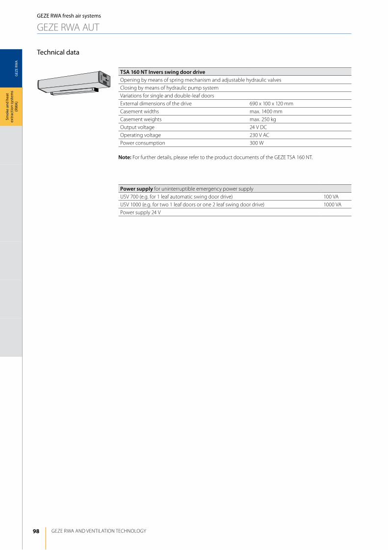
98
GEZ
E RW
A
GEZE RWA ANd VENTilATiON TEChNOlOGy
Smok
e an
d he
at
extr
actio
n sy
stem
s (R
WA
)
Technical data
Power supply for uninterruptible emergency power supply
USV 700 (e.g. for 1 leaf automatic swing door drive) 100 VA
USV 1000 (e.g. for two 1 leaf doors or one 2 leaf swing door drive) 1000 VA
Power supply 24 V
TSA 160 NT Invers swing door driveOpening by means of spring mechanism and adjustable hydraulic valves
Closing by means of hydraulic pump system
Variations for single and double-leaf doors
External dimensions of the drive 690 x 100 x 120 mm
Casement widths max. 1400 mm
Casement weights max. 250 kg
Output voltage 24 V dC
Operating voltage 230 V AC
Power consumption 300 W
Note: For further details, please refer to the product documents of the GEZE TSA 160 NT.
GEZE RWA fresh air systems
GEZE RWA AUT
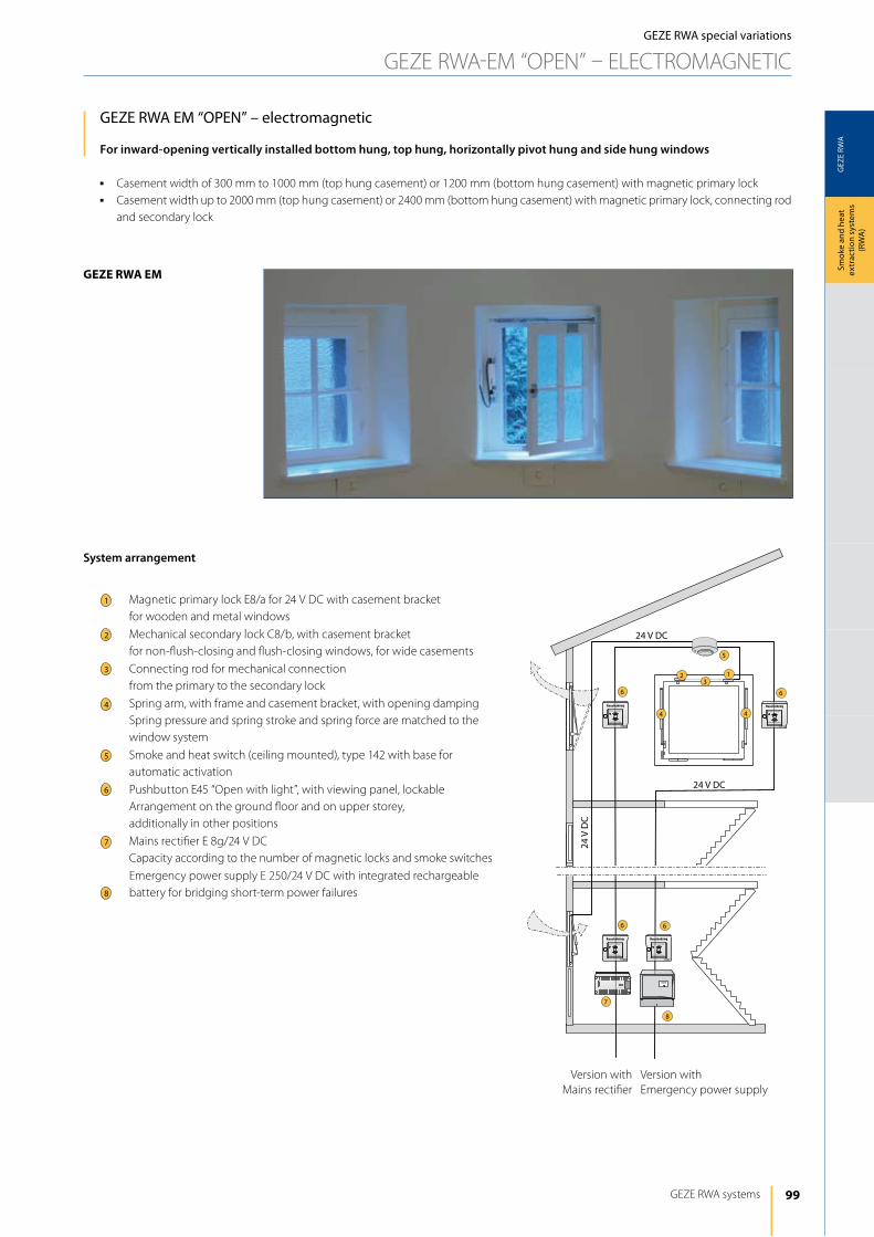
99
GEZ
E RW
A
5
23
1
44
6 6
6 6
7
8
24 V
DC
24 V DC
24 V DC
GEZE RWA systems
Smok
e an
d he
at
extr
actio
n sy
stem
s (R
WA
)
geze rwA em
GEZE RWA special variations
GEZE RWA-EM “OPEN” – ElECTROMAGNETiC
GEZE RWA EM “OPEN” – electromagnetic
For inward-opening vertically installed bottom hung, top hung, horizontally pivot hung and side hung windows
j Casement width of 300 mm to 1000 mm (top hung casement) or 1200 mm (bottom hung casement) with magnetic primary lockj Casement width up to 2000 mm (top hung casement) or 2400 mm (bottom hung casement) with magnetic primary lock, connecting rod
and secondary lock
Version with Mains rectifier
Version with Emergency power supply
1
3
4
5
6
7
8
2
System arrangement
Magnetic primary lock E8/a for 24 V dC with casement bracket for wooden and metal windows
Mechanical secondary lock C8/b, with casement bracket for non-flush-closing and flush-closing windows, for wide casements
Connecting rod for mechanical connection from the primary to the secondary lock
Spring arm, with frame and casement bracket, with opening dampingSpring pressure and spring stroke and spring force are matched to the window system
Smoke and heat switch (ceiling mounted), type 142 with base for automatic activation
Pushbutton E45 “Open with light”, with viewing panel, lockableArrangement on the ground floor and on upper storey, additionally in other positions
Mains rectifier E 8g/24 V dCCapacity according to the number of magnetic locks and smoke switches
Emergency power supply E 250/24 V dC with integrated rechargeable battery for bridging short-term power failures
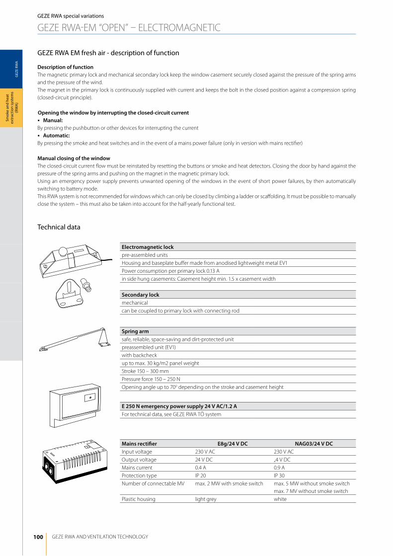
100
GEZ
E RW
A
GEZE RWA ANd VENTilATiON TEChNOlOGy
Smok
e an
d he
at
extr
actio
n sy
stem
s (R
WA
)GEZE RWA special variations
GEZE RWA-EM “OPEN” – ElECTROMAGNETiC
GEZE RWA EM fresh air - description of function
Description of functionThe magnetic primary lock and mechanical secondary lock keep the window casement securely closed against the pressure of the spring arms and the pressure of the wind.The magnet in the primary lock is continuously supplied with current and keeps the bolt in the closed position against a compression spring (closed-circuit principle).
Opening the window by interrupting the closed-circuit currentj Manual:By pressing the pushbutton or other devices for interrupting the currentj Automatic:By pressing the smoke and heat switches and in the event of a mains power failure (only in version with mains rectifier)
Manual closing of the windowThe closed-circuit current flow must be reinstated by resetting the buttons or smoke and heat detectors. Closing the door by hand against the pressure of the spring arms and pushing on the magnet in the magnetic primary lock.Using an emergency power supply prevents unwanted opening of the windows in the event of short power failures, by then automatically switching to battery mode.This RWA system is not recommended for windows which can only be closed by climbing a ladder or scaffolding. it must be possible to manually close the system – this must also be taken into account for the half-yearly functional test.
Technical data
Electromagnetic lockpre-assembled units
housing and baseplate buffer made from anodised lightweight metal EV1
Power consumption per primary lock 0.13 A
in side hung casements: Casement height min. 1.5 x casement width
Secondary lockmechanical
can be coupled to primary lock with connecting rod
Spring armsafe, reliable, space-saving and dirt-protected unit
preassembled unit (EV1)
with backcheck
up to max. 30 kg/m2 panel weight
Stroke 150 – 300 mm
Pressure force 150 – 250 N
Opening angle up to 700 depending on the stroke and casement height
E 250 N emergency power supply 24 V AC/1.2 AFor technical data, see GEZE RWA TÖ system
Mains rectifier E8g/24 V DC NAG03/24 V DCinput voltage 230 V AC 230 V AC
Output voltage 24 V dC „4 V dC
Mains current 0.4 A 0.9 A
Protection type iP 20 iP 30
Number of connectable MV max. 2 MW with smoke switch max. 5 MW without smoke switchmax. 7 MV without smoke switch
Plastic housing light grey white
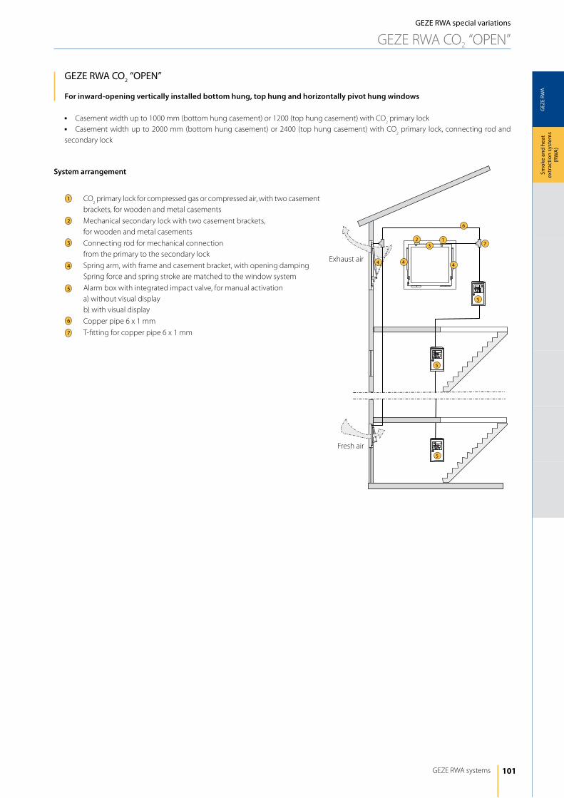
101
GEZ
E RW
A
5
6
5
5
7
4 44
312
GEZE RWA systems
Smok
e an
d he
at
extr
actio
n sy
stem
s (R
WA
)
GEZE RWA special variations
GEZE RWA CO2 “OPEN”
GEZE RWA CO2 “OPEN”
For inward-opening vertically installed bottom hung, top hung and horizontally pivot hung windows
j Casement width up to 1000 mm (bottom hung casement) or 1200 (top hung casement) with CO2 primary lock
j Casement width up to 2000 mm (bottom hung casement) or 2400 (top hung casement) with CO2 primary lock, connecting rod and
secondary lock
Exhaust air
Fresh air
1
3
4
5
6
7
2
System arrangement
CO2 primary lock for compressed gas or compressed air, with two casement
brackets, for wooden and metal casements
Mechanical secondary lock with two casement brackets, for wooden and metal casements
Connecting rod for mechanical connection from the primary to the secondary lock
Spring arm, with frame and casement bracket, with opening dampingSpring force and spring stroke are matched to the window system
Alarm box with integrated impact valve, for manual activationa) without visual displayb) with visual display
Copper pipe 6 x 1 mm
T-fitting for copper pipe 6 x 1 mm

102
GEZ
E RW
A
ZU
GEZE RWA ANd VENTilATiON TEChNOlOGy
Smok
e an
d he
at
extr
actio
n sy
stem
s (R
WA
)GEZE RWA special variations
GEZE RWA CO2 “OPEN”
GEZE RWA CO2 “OPEN” – description of function
Description of functionThe CO
² primary lock and mechanical secondary lock keep the window casement securely closed against the pressure of the spring arms and
the pressure of the wind. The bolt in the primary lock is subjected to spring pressure. The primary lock has a pressure cylinder which is connected to the release stations via a copper cable. The release station (alarm box) is equipped with CO
2 cartridges. These CO
2 cartridges provide the
energy for releasing the windows, independently of other energy sources. The size of the CO2 cartridges must be specified depending on the
number of pressure cylinders and the length of the line.
Opening the windowOn actuating a release station, the CO
2- cartridge is punctured. The CO
2 gas flows through the copper pipe to the pressure cylinders in the
primary locks. The pressure cylinders release the bolt in the windows. The tensioned spring arms open the windows.
Manual closing of the windowThe casements are pressed back manually against the pressing force of the spring arms. The bolts automatically latch into the locks. After closing the punctured CO
2 cartridges in the release station must be replaced. Alarm boxes, from whose position the windows to be opened are seen
do not have to have a visual display. This RWA system is not recommended for windows which can positioned high and can only be closed by climbing ladders or scaffolding, e.g. after each half-yearly function test.
Technical data
CO² primary lockpre-assembled units
housing and baseplate buffer made from anodised lightweight metal EV1
with connecting rod and secondary lock
Connection to copper pipe 6 x 1 mm
Secondary lockmechanical
Spring armsafe, reliable, space-saving and dirt-protected unit
preassembled unit (EV1)
with backcheck
up to max. 30 kg/m2 panel weight
Stroke 150 – 300 mm
Pressure force 150 – 250 N
Opening angle up to 700 depending on the stroke and casement height
Alarm boxinspection window made of glass (2 mm) in the door
door lockable
CO² cartridges 18 g
Push in inspection window in case of emergency
max. 10 primary locks and 70 mm copper pipe 6 x 1 mm
Surface-mounted and flush-mounted version
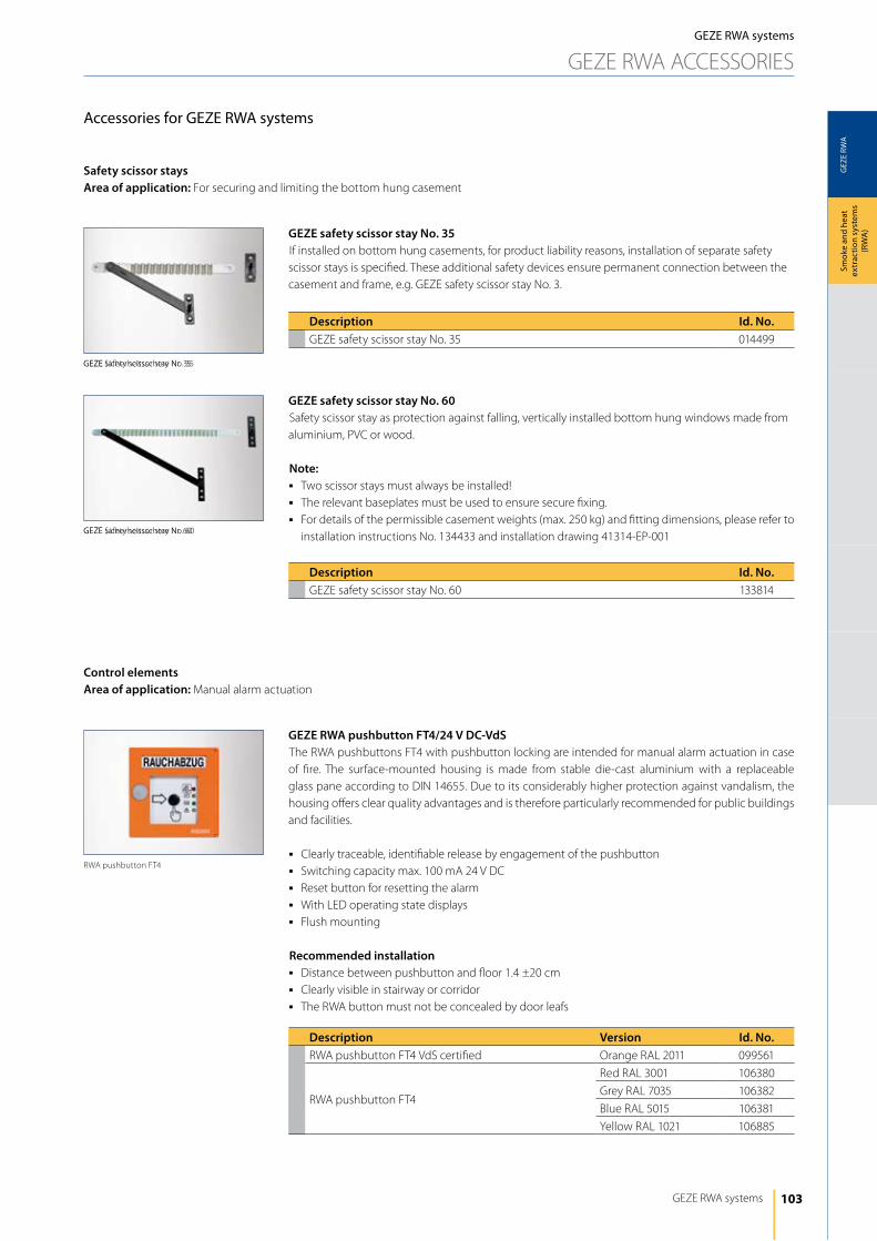
103
GEZ
E RW
A
GEZE Sicherheitsschere Nr. 35
GEZE Sicherheitsschere Nr. 60
GEZE RWA systems
Smok
e an
d he
at
extr
actio
n sy
stem
s (R
WA
)
GEZE RWA systems
GEZE RWA ACCESSORiES
Accessories for GEZE RWA systems
GEZE RWA pushbutton FT4/24 V DC-VdSThe RWA pushbuttons FT4 with pushbutton locking are intended for manual alarm actuation in case of fire. The surface-mounted housing is made from stable die-cast aluminium with a replaceable glass pane according to diN 14655. due to its considerably higher protection against vandalism, the housing offers clear quality advantages and is therefore particularly recommended for public buildings and facilities.
j Clearly traceable, identifiable release by engagement of the pushbuttonj Switching capacity max. 100 mA 24 V dCj Reset button for resetting the alarmj With lEd operating state displaysj Flush mounting
Recommended installationj distance between pushbutton and floor 1.4 ±20 cmj Clearly visible in stairway or corridorj The RWA button must not be concealed by door leafs
Description Version Id. No.RWA pushbutton FT4 VdS certified Orange RAl 2011 099561
RWA pushbutton FT4
Red RAl 3001 106380
Grey RAl 7035 106382
Blue RAl 5015 106381
yellow RAl 1021 106885
Control elementsArea of application: Manual alarm actuation
RWA pushbutton FT4
GEZE safety scissor stay No. 35if installed on bottom hung casements, for product liability reasons, installation of separate safety scissor stays is specified. These additional safety devices ensure permanent connection between the casement and frame, e.g. GEZE safety scissor stay No. 3.
GEZE safety scissor stay No. 60Safety scissor stay as protection against falling, vertically installed bottom hung windows made from aluminium, PVC or wood.
Note:j Two scissor stays must always be installed!j The relevant baseplates must be used to ensure secure fixing.j For details of the permissible casement weights (max. 250 kg) and fitting dimensions, please refer to
installation instructions No. 134433 and installation drawing 41314-EP-001
Description Id. No.GEZE safety scissor stay No. 35 014499
Description Id. No.GEZE safety scissor stay No. 60 133814
Safety scissor staysArea of application: For securing and limiting the bottom hung casement
GEZE safety scissor stay No. 35
GEZE safety scissor stay No. 60
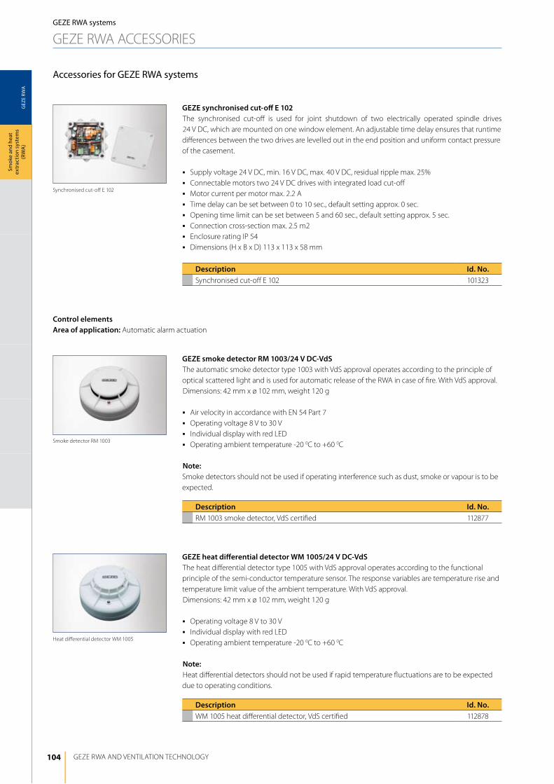
104
GEZ
E RW
A
GEZE RWA ANd VENTilATiON TEChNOlOGy
Smok
e an
d he
at
extr
actio
n sy
stem
s (R
WA
)
GEZE smoke detector RM 1003/24 V DC-VdSThe automatic smoke detector type 1003 with VdS approval operates according to the principle of optical scattered light and is used for automatic release of the RWA in case of fire. With VdS approval.dimensions: 42 mm x ø 102 mm, weight 120 g
j Air velocity in accordance with EN 54 Part 7j Operating voltage 8 V to 30 Vj individual display with red lEdj Operating ambient temperature -20 0C to +60 0C
Note:Smoke detectors should not be used if operating interference such as dust, smoke or vapour is to be expected.
GEZE heat differential detector WM 1005/24 V DC-VdSThe heat differential detector type 1005 with VdS approval operates according to the functional principle of the semi-conductor temperature sensor. The response variables are temperature rise and temperature limit value of the ambient temperature. With VdS approval.dimensions: 42 mm x ø 102 mm, weight 120 g
j Operating voltage 8 V to 30 Vj individual display with red lEdj Operating ambient temperature -20 0C to +60 0C
Note:heat differential detectors should not be used if rapid temperature fluctuations are to be expected due to operating conditions.
GEZE RWA systems
GEZE RWA ACCESSORiES
Description Id. No.RM 1003 smoke detector, VdS certified 112877
Description Id. No.WM 1005 heat differential detector, VdS certified 112878
Accessories for GEZE RWA systems
Control elementsArea of application: Automatic alarm actuation
Smoke detector RM 1003
heat differential detector WM 1005
GEZE synchronised cut-off E 102The synchronised cut-off is used for joint shutdown of two electrically operated spindle drives 24 V dC, which are mounted on one window element. An adjustable time delay ensures that runtime differences between the two drives are levelled out in the end position and uniform contact pressure of the casement.
j Supply voltage 24 V dC, min. 16 V dC, max. 40 V dC, residual ripple max. 25%j Connectable motors two 24 V dC drives with integrated load cut-offj Motor current per motor max. 2.2 Aj Time delay can be set between 0 to 10 sec., default setting approx. 0 sec.j Opening time limit can be set between 5 and 60 sec., default setting approx. 5 sec.j Connection cross-section max. 2.5 m2j Enclosure rating iP 54j dimensions (h x B x d) 113 x 113 x 58 mm
Description Id. No.Synchronised cut-off E 102 101323
Synchronised cut-off E 102

105
GEZ
E RW
A
GEZE RWA systems
Smok
e an
d he
at
extr
actio
n sy
stem
s (R
WA
)
GEZE AS 500 vent switch LTA-24j 24 V mains voltagej Triple switchj With “Open-Stop-Closed” function keysj With lEds to display “Open-Closed”j Flush mounting
GEZE AS 500 vent switch LTA-24-SCTj 24 V mains voltagej Triple switchj With “Open-Stop-Closed” function keysj With lEds to display “Open-Closed”j Combined with key-operated switchj double framej Flush mounting
GEZE AS 500 vent switch LTA-230j 230 Vj Triple switchj With “Open-Stop-Closed” function keysj Flush mounting
GEZE AS 500 vent switch LTA-230-SCTj 230 Vj Triple switchj With “Open-Stop-Closed” function keysj Combined with key-operated switchj double framej Flush mounting
GEZE RWA systems
GEZE RWA ACCESSORiES
Description Id. No.AS 500 vent switch lTA-24 118473
Description Id. No.AS 500 vent switch lTA-24-SCT 127176
Description Id. No.AS 500 vent switch lTA-230 118474
Description Id. No.AS 500 vent switch lTA-230-SCT 118475
Accessories for GEZE RWA systems
Venting modeArea of application: Electrical RWA with additional venting function
Vent switch lTA-230-SCT
Vent switch lTA-230
Vent switch lTA-24-SCT
Vent switch lTA-24
GEZE synchronising unit 24 VThis synchronising unit is suitable for all GEZE electric drives with 24 V.
Description Id. No.Synchronising unit 24 V 111198
Synchronising unit 24 V
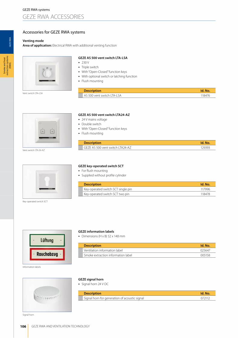
106
GEZ
E RW
A
GEZE RWA ANd VENTilATiON TEChNOlOGy
Smok
e an
d he
at
extr
actio
n sy
stem
s (R
WA
)
Venting modeArea of application: Electrical RWA with additional venting function
GEZE RWA systems
GEZE RWA ACCESSORiES
Accessories for GEZE RWA systems
GEZE AS 500 vent switch LTA24-AZj 24 V mains voltagej double switchj With “Open-Closed” function keys j Flush mounting
GEZE key-operated switch SCTj For flush mountingj Supplied without profile cylinder
Vent switch lTA-24-AZ
Key-operated switch SCT
Description Id. No.GEZE AS 500 vent switch lTA24-AZ 129393
Description Id. No.Key-operated switch SCT single pin 117996
Key-operated switch SCT two pin 118478
GEZE information labelsj dimensions (h x B) 52 x 148 mm
GEZE signal hornj Signal horn 24 V dC
Signal horn
Description Id. No.Ventilation information label 025647
Smoke extraction information label 005158
Description Id. No.Signal horn for generation of acoustic signal 072112
information labels
GEZE AS 500 vent switch LTA-LSAj 230 Vj Triple switchj With “Open-Closed” function keysj With optional switch or latching functionj Flush mounting
Vent switch lTA-lSADescription Id. No.AS 500 vent switch lTA-lSA 118476

107
GEZ
E RW
A
142
3
2 x 2 x 0,8
2 x 2 x 0,8 2 x 2 x 0,8
GEZE RWA systems
Smok
e an
d he
at
extr
actio
n sy
stem
s (R
WA
)
GEZE RWA systems
GEZE RWA ACCESSORiES
Accessories for GEZE RWA systems
Control unit with evaluation electronicsThe control includes the power supply and the potential-free switching contacts with microcontroller control of the rain-wind signals. The evaluation takes place individually or jointly. The weather station is supplied with 24 V dC/GNd/signal input.
Weather stationThe weather station unit contains the rain, wind and temperature sensors. The wind is measured electrically by means of a heated ceramic wire; this removes the need for the usual mechanical measurement using wind scoops. The rain is measured by the gold-plated printed conductors on the surface, which measures even the finest rain.if the rain-wind control is released, the connected vent switches are disabled and all the connected drives are activated to “ClOSEd”. But an alarm has precedence over the rain-wind control, i.e. in the event of an emergency, the windows will be opened even if the rain-wind control is active (the windows are not closed). The switching point of the wind speed sensor can be set between 1-15 m/s.
Visual display unit
Control unit with evaluation electronics, weather station
Description Id. No.Rain-wind control (weather station plus evaluation electronics) 091529
Visual display for optical signals in case of rain and wind activity 029238
1
3
4
2
componentsControl unit with evaluation electronics
Weather station
Visual display unit
Transfer to the emergency power control unit with potential-free switch contact
GEZE rain-wind controlThe rain-wind control unit can be connected to several control units without an additional relay (loop through signal). A rain-wind control unit provided on site by the customer can also be used; this requires a potential-free make contact provided on site by the customer.
GEZE room temperature regulator E70The E70 room temperature regulator is used for control in interior rooms.The temperature switching point can be individually set between 5 0C and 30 0C.
Timerif a timer is connected, windows are opened or closed at preselectable times. Optionally, a timer can be connected to each vent switch line, whereby these must be set to pulse signal, not continuous signal. The timer and vent switches are equal ranked control elements, i.e. the RWA emergency power control unit takes into account the last signal.
Room temperature regulator E70
Description Id. No.Room temperature regulator E70 079087
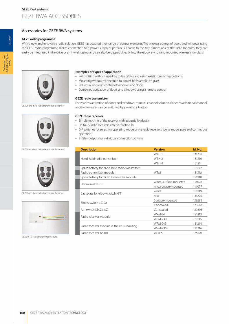
108
GEZ
E RW
A
GEZE RWA ANd VENTilATiON TEChNOlOGy
Smok
e an
d he
at
extr
actio
n sy
stem
s (R
WA
)GEZE RWA systems
GEZE RWA ACCESSORiES
Examples of types of applicationj Retro-fitting without needing to lay cables and using existing switches/buttonsj Mounting without connection to power, for example, on glassj individual or group control of windows and doorsj Combined activation of doors and windows using a remote control
GEZE radio transmitterFor wireless activation of doors and windows, as multi-channel solution. For each additional channel, another terminal can be switched by pressing a button.
GEZE radio receiverj Simple teach-in of the receiver with acoustic feedbackj Up to 85 radio receivers can be teached-inj diP switches for selecting operating mode of the radio receivers (pulse mode, pule and continuous
operation)j 2 Relay outputs for individual connection options
Accessories for GEZE RWA systems
GEZE radio programmeWith a new and innovative radio solution, GEZE has adapted their range of control elements. The wireless control of doors and windows using the GEZE radio programme makes connection to a power supply superfluous. Thanks to the tiny dimensions of the radio modules, they can easily be integrated in the drive or an in-wall casing and can also be clipped directly into the elbow switch and mounted wirelessly on glass.
GEZE hand-held radio transmitter, 1 channel
GEZE hand-held radio transmitter, 2 channel
GEZE hand-held radio transmitter, 4 channel
GEZE WTM radio transmitter module
Description Version Id. No.
hand-held radio transmitter
WTh-1 131209
WTh-2 131210
WTh-4 131211
Spare battery for hand-held radio transmitter 131217
Radio transmitter module WTM 131212
Spare battery for radio transmitter module 131218
Elbow switch KFTwhite, surface-mounted 114078
niro, surface-mounted 114077
Backplate for elbow switch KFTwhite 131219
niro 131220
Elbow switch lS990Surface-mounted 128582
Concealed 128583
Fan switch lTA24-AZ Concealed 129393
Radio receiver moduleWRM-24 131213
WRM-230 131215
Radio receiver module in the iP-54 housingWRM-24B 131214
WRM-230B 131216
Radio receiver board WRB-5 135170
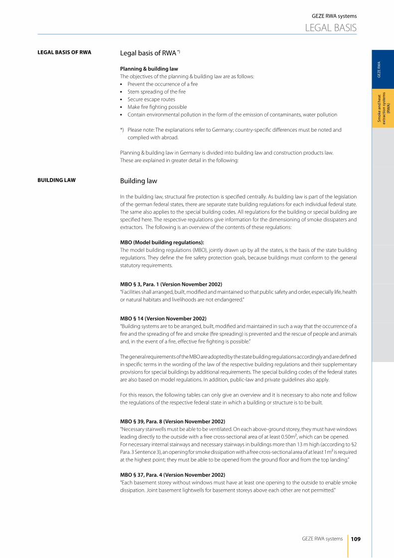
109
GEZ
E RW
A
GEZE RWA systems
Smok
e an
d he
at
extr
actio
n sy
stem
s (R
WA
)
Building law
in the building law, structural fire protection is specified centrally. As building law is part of the legislation of the german federal states, there are separate state building regulations for each individual federal state. The same also applies to the special building codes. All regulations for the building or special building are specified here. The respective regulations give information for the dimensioning of smoke dissipaters and extractors. The following is an overview of the contents of these regulations:
MBO (Model building regulations):The model building regulations (MBO), jointly drawn up by all the states, is the basis of the state building regulations. They define the fire safety protection goals, because buildings must conform to the general statutory requirements.
MBO § 3, Para. 1 (Version November 2002)“Facilities shall arranged, built, modified and maintained so that public safety and order, especially life, health or natural habitats and livelihoods are not endangered.“
MBO § 14 (Version November 2002)“Building systems are to be arranged, built, modified and maintained in such a way that the occurrence of a fire and the spreading of fire and smoke (fire spreading) is prevented and the rescue of people and animals and, in the event of a fire, effective fire fighting is possible.” The general requirements of the MBO are adopted by the state building regulations accordingly and are defined in specific terms in the wording of the law of the respective building regulations and their supplementary provisions for special buildings by additional requirements. The special building codes of the federal states are also based on model regulations. in addition, public-law and private guidelines also apply.
For this reason, the following tables can only give an overview and it is necessary to also note and follow the regulations of the respective federal state in which a building or structure is to be built.
MBO § 39, Para. 8 (Version November 2002)“Necessary stairwells must be able to be ventilated. On each above-ground storey, they must have windows leading directly to the outside with a free cross-sectional area of at least 0.50m², which can be opened. For necessary internal stairways and necessary stairways in buildings more than 13 m high (according to §2 Para. 3 Sentence 3), an opening for smoke dissipation with a free cross-sectional area of at least 1m² is required at the highest point; they must be able to be opened from the ground floor and from the top landing.”
MBO § 37, Para. 4 (Version November 2002)“Each basement storey without windows must have at least one opening to the outside to enable smoke dissipation. Joint basement lightwells for basement storeys above each other are not permitted.”
legal basis of RWA *)
Planning & building lawThe objectives of the planning & building law are as follows:j Prevent the occurrence of a firej Stem spreading of the firej Secure escape routesj Make fire fighting possiblej Contain environmental pollution in the form of the emission of contaminants, water pollution
*) Please note: The explanations refer to Germany; country-specific differences must be noted and complied with abroad.
Planning & building law in Germany is divided into building law and construction products law. These are explained in greater detail in the following:
legAl BASiS oF rwA
Building lAw
GEZE RWA systems
lEGAl BASiS
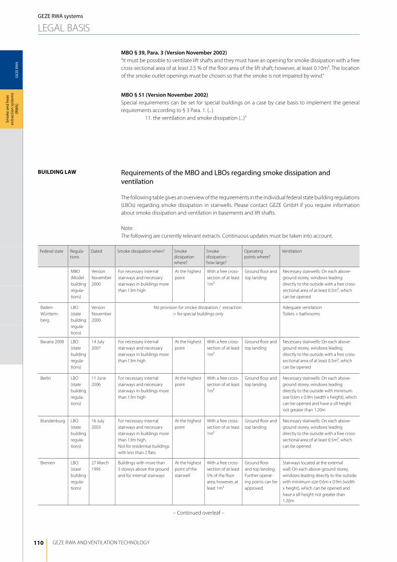
110
GEZ
E RW
A
GEZE RWA ANd VENTilATiON TEChNOlOGy
Smok
e an
d he
at
extr
actio
n sy
stem
s (R
WA
)
MBO § 39, Para. 3 (Version November 2002)“it must be possible to ventilate lift shafts and they must have an opening for smoke dissipation with a free cross-sectional area of at least 2.5 % of the floor area of the lift shaft; however, at least 0.10m². The location of the smoke outlet openings must be chosen so that the smoke is not impaired by wind.“
MBO § 51 (Version November 2002)Special requirements can be set for special buildings on a case by case basis to implement the general requirements according to § 3 Para. 1. (...)
11. the ventilation and smoke dissipation (...)“
Requirements of the MBO and lBOs regarding smoke dissipation and ventilation
The following table gives an overview of the requirements in the individual federal state building regulations (lBOs) regarding smoke dissipation in stairwells. Please contact GEZE Gmbh if you require information about smoke dissipation and ventilation in basements and lift shafts.
Note: The following are currently relevant extracts. Continuous updates must be taken into account.
Building lAw
Federal state Regula-tions
dated Smoke dissipation when? Smoke dissipation where?
Smoke dissipation - how large?
Operating points where?
Ventilation
MBO (Model building regula-tions)
Version November 2000
For necessary internal stairways and necessary stairways in buildings more than 13m high
At the highest point
With a free cross-section of at least 1m²
Ground floor and top landing
Necessary stairwells: On each above-ground storey, windows leading directly to the outside with a free cross-sectional area of at least 0.5m², which can be opened
Baden- Württem-berg
lBO (state building regula-tions)
Version November 2000
No provision for smoke dissipation / extraction -> for special buildings only
Adequate ventilation Toilets + bathrooms
Bavaria 2008 lBO (state building regula-tions)
14 July 2007
For necessary internal stairways and necessary stairways in buildings more than 13m high
At the highest point
With a free cross-section of at least 1m²
Ground floor and top landing
Necessary stairwells: On each above-ground storey, windows leading directly to the outside with a free cross-sectional area of at least 0.5m², which can be opened
Berlin lBO (state building regula-tions)
11 June 2006
For necessary internal stairways and necessary stairways in buildings more than 13m high
At the highest point
With a free cross-section of at least 1m²
Ground floor and top landing
Necessary stairwells: On each above-ground storey, windows leading directly to the outside with minimum size 0.6m x 0.9m (width x height), which can be opened and have a sill height not greater than 1.20m
Brandenburg lBO (state building regula-tions)
16 July 2003
For necessary internal stairways and necessary stairways in buildings more than 13m high. Not for residential buildings with less than 2 flats
At the highest point
With a free cross-section of at least 1m²
Ground floor and top landing
Necessary stairwells: On each above-ground storey, windows leading directly to the outside with a free cross-sectional area of at least 0.5m², which can be opened
Bremen lBO (state building regula-tions)
27 March 1995
Buildings with more than 5 storeys above the ground and for internal stairways
At the highest point of the stairwell
With a free cross-section of at least 5% of the floor area; however, at least 1m²
Ground floor and top landing. Further operat-ing points can be approved.
Stairways located at the external wall: On each above-ground storey, windows leading directly to the outside with minimum size 0.6m x 0.9m (width x height), which can be opened and have a sill height not greater than 1.20m
GEZE RWA systems
lEGAl BASiS
– Continued overleaf –
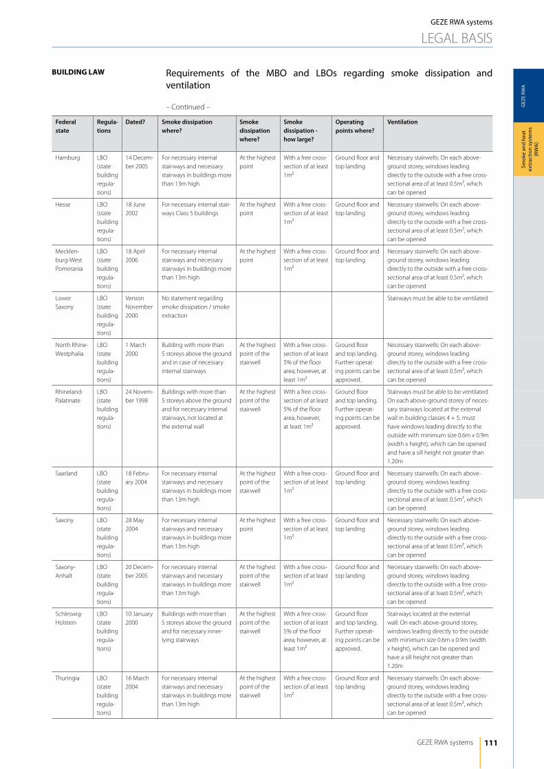
111
GEZ
E RW
A
GEZE RWA systems
Smok
e an
d he
at
extr
actio
n sy
stem
s (R
WA
)
Building lAw
GEZE RWA systems
lEGAl BASiS
Federal state
Regula-tions
Dated? Smoke dissipation where?
Smoke dissipation where?
Smoke dissipation - how large?
Operating points where?
Ventilation
hamburg lBO (state building regula-tions)
14 decem-ber 2005
For necessary internal stairways and necessary stairways in buildings more than 13m high
At the highest point
With a free cross-section of at least 1m²
Ground floor and top landing
Necessary stairwells: On each above-ground storey, windows leading directly to the outside with a free cross-sectional area of at least 0.5m², which can be opened
hesse lBO (state building regula-tions)
18 June 2002
For necessary internal stair-ways Class 5 buildings
At the highest point
With a free cross-section of at least 1m²
Ground floor and top landing
Necessary stairwells: On each above-ground storey, windows leading directly to the outside with a free cross-sectional area of at least 0.5m², which can be opened
Mecklen-burg-West Pomerania
lBO (state building regula-tions)
18 April 2006
For necessary internal stairways and necessary stairways in buildings more than 13m high
At the highest point
With a free cross-section of at least 1m²
Ground floor and top landing
Necessary stairwells: On each above-ground storey, windows leading directly to the outside with a free cross-sectional area of at least 0.5m², which can be opened
lower Saxony
lBO (state building regula-tions)
Version November 2000
No statement regarding smoke dissipation / smoke extraction
Stairways must be able to be ventilated
North Rhine-Westphalia
lBO (state building regula-tions)
1 March 2000
Building with more than 5 storeys above the ground and in case of necessary internal stairways
At the highest point of the stairwell
With a free cross-section of at least 5% of the floor area; however, at least 1m²
Ground floor and top landing. Further operat-ing points can be approved.
Necessary stairwells: On each above-ground storey, windows leading directly to the outside with a free cross-sectional area of at least 0.5m², which can be opened
Rhineland-Palatinate
lBO (state building regula-tions)
24 Novem-ber 1998
Buildings with more than 5 storeys above the ground and for necessary internal stairways, not located at the external wall
At the highest point of the stairwell
With a free cross-section of at least 5% of the floor area; however, at least 1m²
Ground floor and top landing. Further operat-ing points can be approved.
Stairways must be able to be ventilatedOn each above-ground storey of neces-sary stairways located at the external wall in building classes 4 + 5, must have windows leading directly to the outside with minimum size 0.6m x 0.9m (width x height), which can be opened and have a sill height not greater than 1.20m
Saarland lBO (state building regula-tions)
18 Febru-ary 2004
For necessary internal stairways and necessary stairways in buildings more than 13m high
At the highest point of the stairwell
With a free cross-section of at least 1m²
Ground floor and top landing
Necessary stairwells: On each above-ground storey, windows leading directly to the outside with a free cross-sectional area of at least 0.5m², which can be opened
Saxony lBO (state building regula-tions)
28 May 2004
For necessary internal stairways and necessary stairways in buildings more than 13m high
At the highest point
With a free cross-section of at least 1m²
Ground floor and top landing
Necessary stairwells: On each above-ground storey, windows leading directly to the outside with a free cross-sectional area of at least 0.5m², which can be opened
Saxony-Anhalt
lBO (state building regula-tions)
20 decem-ber 2005
For necessary internal stairways and necessary stairways in buildings more than 13m high
At the highest point of the stairwell
With a free cross-section of at least 1m²
Ground floor and top landing
Necessary stairwells: On each above-ground storey, windows leading directly to the outside with a free cross-sectional area of at least 0.5m², which can be opened
Schleswig-holstein
lBO (state building regula-tions)
10 January 2000
Buildings with more than 5 storeys above the ground and for necessary inner-lying stairways
At the highest point of the stairwell
With a free cross-section of at least 5% of the floor area; however, at least 1m²
Ground floor and top landing. Further operat-ing points can be approved.
Stairways located at the external wall: On each above-ground storey, windows leading directly to the outside with minimum size 0.6m x 0.9m (width x height), which can be opened and have a sill height not greater than 1.20m
Thuringia lBO (state building regula-tions)
16 March 2004
For necessary internal stairways and necessary stairways in buildings more than 13m high
At the highest point of the stairwell
With a free cross-section of at least 1m²
Ground floor and top landing
Necessary stairwells: On each above-ground storey, windows leading directly to the outside with a free cross-sectional area of at least 0.5m², which can be opened
Requirements of the MBO and lBOs regarding smoke dissipation and ventilation
– Continued –
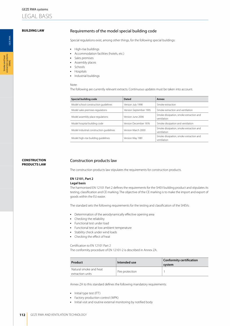
112
GEZ
E RW
A
GEZE RWA ANd VENTilATiON TEChNOlOGy
Smok
e an
d he
at
extr
actio
n sy
stem
s (R
WA
)GEZE RWA systems
lEGAl BASiS
Requirements of the model special building code
Special regulations exist, among other things, for the following special buildings:
j high-rise buildingsj Accommodation facilities (hotels, etc.)j Sales premisesj Assembly placesj Schoolsj hospitalsj industrial buildings
Note:The following are currently relevant extracts. Continuous updates must be taken into account.
Building lAw
Special building code Dated Annex
Model school construction guidelines Version July 1998 Smoke extraction
Model sales premises regulations Version September 1995 Smoke extraction and ventilation
Model assembly place regulations Version June 2006Smoke dissipation, smoke extraction and ventilation
Model hospital building code Version december 1976 Smoke dissipation and ventilation
Model industrial construction guidelines Version March 2000Smoke dissipation, smoke extraction and ventilation
Model high-rise building guidelines Version May 1981Smoke dissipation, smoke extraction and ventilation
Construction products law
The construction products law stipulates the requirements for construction products.
EN 12101, Part 2Legal basisThe harmonised EN 12101 Part 2 defines the requirements for the ShEV building product and stipulates its testing, classification and CE marking. The objective of the CE marking is to make the import and export of goods within the EU easier.
The standard sets the following requirements for the testing and classification of the ShEVs:
j determination of the aerodynamically effective opening areaj Checking the reliabilityj Functional test under loadj Functional test at low ambient temperaturej Stability check under wind loadsj Checking the effect of heat
Certification to EN 12101 Part 2The conformity procedure of EN 12101-2 is described in Annex ZA.
conStruction productS lAw
Product Intended useConformity certification system
Natural smoke and heat extraction units
Fire protection 1
Annex ZA to this standard defines the following mandatory requirements:
j initial type test (iTT)j Factory production control (WPK)j initial visit and routine external monitoring by notified body
113
GEZ
E RW
A
GEZE RWA systems
Smok
e an
d he
at
extr
actio
n sy
stem
s (R
WA
)
Servicing and maintenance
According to the MBO, owners and clients are obliged to ensure proper maintenance, as “buildings and structures ...() shall be arranged, built, modified and maintained so that public safety and order, especially life, health and natural habitats and livelihoods are not endangered”. Construction projects may not be used without proper maintenance (cf. §3 Para. 1 and 2 MBO).The client or owner shall independently ensure servicing, maintenance and inspection. All structural members and components shall be regularly checked for damage or deformations. The owner/operator of an RWA system is obliged to take all necessary safety precautions to avert hazards endangering people and property in the building.By ensuring the function of the smoke and heat extraction systems through regular maintenance, they decisively reduce the actual risk of damage and injuries and also reduce the risk of liability in the event of an incident or claim. in this way they can document at any time that they have fulfilled their obligation to keep the RWA systems ready for use and operation.
A selection of regulations and laws
Constitutional law Art. 2:“Each person has the right to freedom from bodily harm.”
MBO § 3, Para. 1 (Version November 2002)“Facilities shall arranged, built, modified and maintained so that public safety and order, especially life, health or natural habitats and livelihoods are not endangered.“
MBO § 14 (Version November 2002)“Building systems are to be arranged, built, modified and maintained in such a way that the occurrence of a fire and the spreading of fire and smoke (fire spreading) is prevented and the rescue of people and animals and, in the event of a fire, effective fire fighting is possible.”
GEZE drives certified to EN 12101 Part 2 and tested GEZE ShEVs can be installed, are shown separately in Chapter 6ff. For a more precise system description and more detailed information on the topic of ShEV you can refer to the GEZE ShEV system document.
Further important guidelines are MLAR (Model Cable Systems Guidelines - “Musterleitungsanlagen-Richtlinie”) and DIN VDE 0833: Requirements for cables - MLAR (Version March 2000)According to the model cable systems guidelines (MlAR), functional endurance classification E30 is sufficient for natural smoke extraction systems. These cables must be tested and approved according to diN 4102 Part 12. The cables must be laid according to the specifications of the cable manufacturer, with the appropriate fixing materials.
Exceptions according to the MLAR (Version March 2000)Functional endurance for the RWA cables is not necessary if a fire early detection release element with SMOKE variable (smoke detector) monitors the complete cable route and release of the automatic detector results in opening of the RWA. The practical consequence of this is: Rooms through which an RWA cable is routed and in which RWA c omponents are installed must be monitored by smoke detectors if the cable is not laid to E30 standard.
Concealed, flush layingit must be noted that concealed, flush laying (under plaster) is not an approved type of laying to achieve functional endurance based on diN 4102 Part 12. if the functional endurance requirement is to be fulfilled with concealed cables, they must also be to classification E30 or the room must be secured by smoke detectors.
Operating timeReferring to DIN VDE 0833-2 (6.1.6 / 2004) , in the event of a power failure, the RWA must also be able to “at least maintain operation for an operating period of 72 hours”.
conStruction productS lAw
SerVicing And mAintenAnce
GEZE RWA systems
lEGAl BASiS
114
GEZ
E RW
A
GEZE RWA ANd VENTilATiON TEChNOlOGy
Smok
e an
d he
at
extr
actio
n sy
stem
s (R
WA
)
SerVicing And mAintenAnce
GEZE RWA systems
lEGAl BASiS
DIN VDE 0833-1 (5.3.4 / 2003)“Maintenance must be carried out according to the manufacturer's instructions – taking into account the particular operating conditions - however, at least annually.“
DIN 18232 Part 2 (Version November 2007)At regular intervals according to the manufacturer's instructions, usually once a year, smoke extraction systems and their actuators and controls, opening units, power supply cables and their accessories must be inspected to ensure they are in good working order and ready for operation and if necessary must be repaired. The inspections and maintenance work must be noted in an inspection log. inspections are to be carried out by specialist firms qualified for NRA only.
Regulations concerning the monitoring of building services systemsSupplementary to the regular annual maintenance, RWA in so-called buildings and structures of a special type and use, e.g. commercial properties (office blocks with or without shops), assembly places, large garages, must be inspected at three-year intervals by a competent expert licensed under the building legislation/by the state. Regular maintenance is an essential prerequisite for these statutory inspections. The maintenance firm usually undertakes the obligation of the owner/operator to providing suitable qualified personnel for the inspection of the systems by the competent expert. in the inspection regulations for technical systems and building services of the individual federal states, the requirement for maintenance and servicing is specified separately.
Therefore, the following points should be guaranteed with respect to the servicing and maintenance of RWA systems:- RWA systems are to be serviced and if necessary repaired at least once a year.- The servicing/maintenance may only be carried out by competent, qualified persons. This competence
must be verified. Authorisation must be given by GEZE.- inspections must be noted in an inspection log.
Assistance during installation and startupGEZE offers system advice assistance, either by authorised partner firms or personnel from the head office. The installation and functional testing of an RWA must always be carried out by the manufacturer or a specialist firm authorised by the manufacturer, as this is the only way to ensure that the system-relevant functions are completely fulfilled. The RWA acceptance must be accepted by a competent expert.
115
GEZ
E RW
A
GEZE RWA systems
Smok
e an
d he
at
extr
actio
n sy
stem
s (R
WA
)
Steps for RWA system design
Calculation of the smoke extraction areaSmoke extraction is the removal of smoke in case of fire (hot smoke removal). A stable, low-smoke layer results close to the floor which enables safe use of escape routes. A ShEV in accordance with EN 12101 Part 2 must, in Germany, always be used if natural “smoke extraction” is required by the building regulations.Cold smoke removal is used for smoke dissipation, used to remove the remaining smoke in the building after a fire. This is not a safety relevant construction product listed in construction regulations list C.
The smoke extraction area is calculated using the design group, room height and the height of the low-smoke layer from the relevant Table 3 of diN 18232 Part 2 per smoke compartment. This total smoke extraction area is then divided between an appropriate number of façade openings and skylights (NRA: natural smoke extraction). The relevant regulations provided by the standard must be taken into account.
The façade openings determined in this way should each be installed with a maximum distance of 0.5 m between the top edge of the façade openings and the ceiling in at least two opposite external walls of a smoke compartment. The façade openings should be located completely in the smoke compartment; the bottom edge of the discharge opening should be at least 0.5 m above the limit of the calculated low-smoke layer (in accordance with table 3, diN 18232 Part 2).
Calculation of the fresh air area The fresh air areas must be located completely within the low-smoke layer and be at least 1.5 times the size of the exhaust air area. in addition, the correction factors in accordance with EN 18232-2 must be noted and taken into account.The top edge of the fresh air opening must be at least 1 m from the smoke layer limit. in the area of doors or windows with maximum 1.25 m width, this distance can be reduced to 0.5 m. it must always be ensured that the inflowing air does not flow directly into the smoky gas layer and that this impetus does not cause swirling of the smoky gases. The fresh air must be fed into the building close to the floor and at the greatest possible distance from the smoky gas layer.
Various systems are available as drive units for exhaust air and fresh air openings. linear, spindle, scissor stay and chain drives have been tried and tested in practice for many years and nowadays represent state of the art standards. The different systems are available in different performance classes. depending on the opening system (dimensions, weight, installation situation), a drive can be selected which guarantees perfect functional safety for years.
Design of the controlThe RWA emergency power control unit is the central control unit to which all components are connected. in case of a fire they provide the power supply for the RWA openings for at least 72h via rechargeable batteries. Therefore, the power consumption of the individual components must be determined during the planning and the performance class of the central control unit must be selected accordingly.
Planning the wiringAccording to the model cable systems guidelines (MlAR), functional endurance classification E30 is sufficient for natural smoke extraction systems. These cables must be tested and approved according to diN 4102 Part 12. The cables must be laid according to the specifications of the cable manufacturer, with the appropriate fixing materials.
Exceptions according to the MlAR (Version March 2000):Functional endurance for the RWA cables is not necessary if a fire early detection release element with SMOKE variable (smoke detector) monitors the complete cable route and release of the automatic detector results in opening of the RWA. The practical consequence of this is: Rooms through which an RWA cable is routed and in which RWA components are installed must be monitored by smoke detectors if the cable is not laid to E30 standard.
Concealed, flush laying: it must be noted that concealed, flush laying (under plaster) is not an approved type of laying to achieve functional endurance based on diN 4102 Part 12. if the functional endurance requirement is to be fulfilled with concealed cables, they must also be to classification E30 or the room must be secured by smoke detectors.
Safety with ventilation power
GEZE RWA SySTEMS
rw
A S yst e m s
geze gmbhp.o. Box 136371226 leonberggermany
geze gmbhreinhold-Vöster-Straße 21-2971229 leonberggermanytelefon +49 (0) 7152-203-0telefax +49 (0) 7152-203-310
www.geze.com
germanyGEZE Sonderkonstruktionen GmbHPlanken 197944 Boxberg-SchweigernTel. +49 (0) 7930-9294-0Fax +49 (0) 7930-9294-10E-Mail: [email protected]
GEZE GmbHNiederlassung Nord/OstBühringstraße 813086 Berlin (Weissensee)Tel. +49 (0) 30-47 89 90-0Fax +49 (0) 30-47 89 90-17E-Mail: [email protected]
GEZE GmbHNiederlassung WestNordsternstraße 6545329 EssenTel. +49 (0) 201-83082-0 Fax +49 (0) 201-83082-20E-Mail: [email protected]
GEZE GmbHNiederlassung MitteAdenauerallee 261440 Oberursel (b. Frankfurt)Tel. +49 (0) 6171-63610-0Fax +49 (0) 6171-63610-1E-Mail: [email protected]
GEZE GmbHNiederlassung SüdReinhold-Vöster-Straße 21-2971229 leonbergTel. +49 (0) 7152-203-594Fax +49 (0) 7152-203-438E-Mail: [email protected]
GEZE Service GmbH Nl SüdwestReinhold-Vöster-Straße 2571229 leonbergTel. +49 (0) 7152-92 33 34
GEZE Service GmbH Nl Nord-OstBühringstraße 813086 Berlin (Weissensee)Tel. +49 (0) 30-47 02 17 32
GEZE Service GmbH Nl WestNordsternstraße 6545329 EssenTel. +49 (0) 201-8 30 82 16
GEZE Service GmbH Nl MitteAdenauerallee 261440 OberurselTel. +49 (0) 6171-63 61 03
GEZE Service GmbH Nl SüdKeltenring 1085658 EgmatingTel. +49 (0) 8095-87 13 61
AustriaGEZE Austria GmbHMayrwiesstraße 125300 Hallwang b. SalzburgTel. +43-(0)662-663142Fax +43-(0)662-663142-15E-Mail: [email protected]
Baltic StatesGEZE GmbH Baltic States officeDzelzavas iela 120 S1021 RigaTel. +371 (0) 67 89 60 35Fax +371 (0) 67 89 60 36E-Mail: [email protected]
BeneluxGEZE Benelux B.V.leemkuil 1Industrieterrein Kapelbeemd5626 EA EindhovenTel. +31-(0)40-26290-80Fax +31-(0)40-26 290-85E-Mail: [email protected]
BulgariaGEZE Bulgaria - Trade Representative Office61 Pirinski Prohod, entrance „B“, 4th floor, office 5, 1680 SofiaTel. +359 (0) 24 70 43 73 Fax +359 (0) 24 70 62 62E-Mail: [email protected]
indiaGEZE India Private ltd.MF 2 & 3, Guindy Industrial EstateEkkattuthangalChennai 600 097TamilnaduTel. +91 44 3061 6900Fax +91 44 3061 6901E-Mail: [email protected]
italyGEZE Italia SrlVia Giotto, 420040 Cambiago (MI)Tel. +3902950695-11Fax +3902950695-33E-Mail: [email protected]
GEZE Engineering Roma SrlVia lucrezia Romana, 9100178 RomaTel. +3906-7265311Fax +3906-72653136E-Mail: [email protected]
polandGEZE Polska Sp.z o.o.ul. Annopol 2103-236 WarszawaTel. +48 (0)22 440 4 440Fax +48 (0)22 440 4 400E-Mail: [email protected]
romaniaGEZE Romania s.r.l.IRIDE Business Park,Str. Dimitrie Pompeiu nr. 9-9a,Building 10, level 2, Sector 2,020335 BucharestTel.: +40 (0) 21 25 07 750Fax: +40 (0) 21 25 07 750E-Mail: [email protected]
russian FederationGEZE GmbH Representative Office RussiaKolodesnij pereulok3, str. 25 Office Nr. 5201-5203107076 MoskauTel. +7 (0) 49 55 89 90 52Fax +7 (0) 49 55 89 90 51E-Mail: [email protected]
Scandinavia – SwedenGEZE Scandinavia ABMallslingan 10Box 706018711 Täby, SwedenTel. +46(0)8-7323-400Fax +46(0)8-7323-499E-Mail: [email protected]
Scandinavia – norwayGEZE Scandinavia AB avd. NorgeIndustriveien 34 B2073 DalTel. +47(0)639-57200Fax +47(0)639-57173E-Mail: [email protected]
Scandinavia – FinlandBranch office of GEZE Scandinavia ABHerralantie 824Postbox 2015871 HollolaTel. +358(0)10-4005100Fax +358(0)10-4005120E-Mail: [email protected]
Scandinavia – denmarkGEZE DanmarkBranch office of GEZE Scandinavia AB Høje Taastrup Boulevard 532630 TaastrupTel. +45(0)46-323324Fax +45(0)46-323326E-Mail: [email protected]
South AfricaDClSA Distributors (Pty.) ltd.118 Richards Drive, Halfway House,Ext 111P.O. Box 7934, Midrand 1685Tel. +27(0)113158286Fax +27(0)113158261E-Mail: [email protected]
SwitzerlandGEZE Schweiz AGBodenackerstrasse 794657 DullikenTel. +41-(0)62-2855400Fax +41-(0)62-2855401E-Mail: [email protected]
turkeyGEZE GmbH Türkiye - İstanbul İrtibat BürosuAtaşehir Bulvarı, Ata 2/3 Plaza Kat: 9 D: 84 Ataşehir Kadıköy / İstanbulTel. + 90 (0) 21 64 55 43 15Fax + 90 (0) 21 64 55 82 15E-Mail: [email protected]
ukraineRepräsentanz GEZE GmbH ukraineul. Vikentiya Hvoyki, 21,office 15104080 KievTel. +38 (0) 44 49 97 725Fax +38 (0) 44 49 97 725E-Mail: [email protected]
united Arab emirates/gccGEZE Middle EastP.O. Box 17903Jebel Ali Free Zone DubaiTel. +971(0)4-8833112Fax +971(0)4-8833240E-Mail: [email protected]
united KingdomGEZE uK ltd.Blenheim WayFradley ParklichfieldStaffordshire WS13 8SYTel. +44(0)1543443000Fax +44(0)1543443001E-Mail: [email protected]
chinaGEZE Industries (Tianjin) Co., ltd.Shuangchenzhong RoadBeichen Economic DevelopmentArea (BEDA)Tianjin 300400, P.R. ChinaTel. +86(0)22-26973995-0Fax +86(0)22-26972702E-Mail: [email protected]
GEZE Industries (Tianjin) Co., ltd.Branch Office Shanghaiunit 25N, Cross Region PlazaNo 899, ling ling Road, XuHui District200030 Shanghai, P.R ChinaTel. +86 (0)21-523 40 960Fax +86 (0)21-644 72 007E-Mail: [email protected]
GEZE Industries (Tianjin) Co., ltd.Branch Office GuangzhouRoom 17C3Everbright Bank Building, No.689Tian He Bei Road510630 GuangzhouP.R. ChinaTel. +86(0)20-38731842Fax +86(0)20-38731834E-Mail: [email protected]
GEZE Industries (Tianjin) Co., ltd.Branch Office BeijingRm3A02, Building 3ZhuBang 2000 Business PlazaNo.98, Balizhuang xiliChaoyang District100025 Beijing, P.R.ChinaTel. +86 (0)10-8797 5177 /-78Fax +86 (0)10-8797 5171E-Mail: [email protected]
FranceGEZE France S.A.R.l.ZAC de l’Orme RondRN 1977170 ServonTel. +33-(0)1-606260-70Fax +33-(0)1-606260-71E-Mail: [email protected]
hungaryGEZE Hungary Kft.Bartók Béla út 105-113.BudapestH-1115Tel. +36 (1) 481 4670Fax +36 (1) 481 4671E-Mail: [email protected]
iberiaGEZE Iberia S.R.l.Pol. Ind. El PlaC/Comerc, 2-22, Nave 1208980 Sant Feliu de llobregat (Barcelona)Tel. +34(0)9-02194036Fax +34(0)9-02194035E-Mail: [email protected]
G E Z E R WA A N d V E N T i l AT i O N T E C h N O lO G y
id. No. 127785 · Version EN 100312 · All rights reserved
G E Z E R E P R E S E N TAT i V E