3. packet data transfer across egprs and wcdma · pdf filepacket data transfer across egprs...
TRANSCRIPT

3. Packet Data Transfer across EGPRS and WCDMA networks
Dr. David Soldani([email protected], tel. +358.50.3633527)S-38.3215 Special Course on Networking Technology for Ph.D. students at TKK

2 S-38.3215 Special Course on Networking Technology / David Soldani / Fall 2006
Outline
Packet data through EGPRS networksUser plane protocolsControl plan protocolsRadio channels and frame structure
Packet data through (enhanced) WCDMA networksUser plane protocolsControl plan protocolsRadio channels and timingHSPA fundamentals

3 S-38.3215 Special Course on Networking Technology / David Soldani / Fall 2006
EGPRS: UP protocol stacks
Relay
NetworkService
GTP-U
Application
IP
SNDCP
LLC
RLC
MAC
GSM RF L1bisGSM RF
BSSGP
L1bis
Relay
L2
L1
IP
L2
L1
IP
GTP-U
IP
Um Gb Gn GiMS BSS SGSN GGSN
NetworkService
UDPUDP
BSC
BTS
10 11
12 13
0 1
2 3
6
4 5
7 8 9
Packet Control Unit (PCU)• MAC/RLC functions
Channel Coding Unit (CCU)• L1 functions
Sub-Network Dependent Convergence Protocol (SNDCP)• Header compression/decompression (e.g. TCP/IP)• Mux N-PDUs (same QoS) of NSAPI(s) onto LLC-SAPI• Segmentation/reassembly of LLC frames of max length
SNDCP
Logical Link Control Protocol (LLC)• AM, UM and ciphering• Mux of LLC frames onto BSSGP virtual connections
LLC
Radio Link CP (RLC)• Segmentation/reassembly RLC PDUs• AM, UM
RLC
MAC
Medium Access CP (MAC)• Share of PDCHs between MSs• Allows MS to used more PDCHs
BSS GPRS Protocol (BSSGP)• SGSN-BSS flow control• PTP, PTM and signaling peers
BSSGP

4 S-38.3215 Special Course on Networking Technology / David Soldani / Fall 2006
Abis
BSC SGSNBTSCCU
CCU
UmGb
PCU
Packet-switchingCircuit-switchingGn
GGSN
Packet-switching
MS
MS
One tunnel per PDP Context(NSAPI, TLLI, TEID)
LLC connection: BSS Packet Flow Context (PFC)= Mux of N-PDUs from one or more NSAPIs
(DLCI(s) = TLLI + SAPI(s))(LLC–SAPI = NSAP(s))
BSS Virtual Connection= Mux of LLC frames
(BVCI = Cell ID)
One RR connection (TBF)over one or more PDCH(s)
( TS(s) )RR (RLC/MAC) Connection:Temporary Block Flow (TBF)
( TFI)
PCU Frames
Radio Block(s) (4 bursts each = 20ms) on PDTCHCS 1 – CS 4 (GPRS)
MCS 1 – MCS 9 (EGPRS)(M-CS)
One BSS context per MS• BSS PFCs (PFIs)• Aggregate BSS QoS Profile(s)
One MM context per MS• PDP context(s)• QoS Profile(s)• Radio priority (UL)• PFI(s)• Aggregate BSS QoS Profile(s)
• PDP context(s)• QoS Profile(s)• TFT(s)
One MM context• PDP context(s)• QoS Profile(s)• TFT(s)• Radio priority (UL)• PFI(s)
External PDN
EGPRS: End-to-end data transmission

5 S-38.3215 Special Course on Networking Technology / David Soldani / Fall 2006
R98: GPRS channel coding
For a Radio Block (RB) carrying a RLC data block, where 1 Radio Block = 4 bursts (20 ms)
Note: 1 GMSK symbol = 1 bit
Scheme Code rate Radio block size (Bytes)
Modulation Data rate (kb/s)
Data rate excluding RLC/MAC headers (kb/s)
CS-1 ½ 23 GMSK 9.05 8 CS-2 ≈ 2/3 34 GMSK 13.4 12 CS-3 ≈ 3/4 39 GMSK 15.6 14.4 CS-4 1 54 GMSK 21.4 20

6 S-38.3215 Special Course on Networking Technology / David Soldani / Fall 2006
R99: EGPRS channel coding
For RB carrying one or more RLC data blocks
Note: 1 8PSK symbol = 3 bits
Scheme Code rate Header Code rate Modulation RLC blocks per Radio Block (20ms)
Raw Data within one Radio Block
Data rate(kb/s)
MCS-9 1.0 0.36 2 2x592 59.2 MCS-8 0.92 0.36 2 2x544 54.4 MCS-7 0.76 0.36 2 2x448 44.8 MCS-6 0.49 1/3 1 592
48+544 29.6 27.2
MCS-5 0.37 1/3
8PSK
1 448 22.4 MCS-4 1.0 0.53 1 352 17.6 MCS-3 0.85 0.53 1 296
48+248 and 296 14.8 13.6
MCS-2 0.66 0.53 1 224 11.2 MCS-1 0.53 0.53
GMSK
1 176 8.8 NOTE: The italic captions indicate the 6 octets (48 bits) of padding when retransmitting an MCS-8 block with MCS-3 or MCS-6. For MCS-3, the 6 octets of padding are sent every second block.

7 S-38.3215 Special Course on Networking Technology / David Soldani / Fall 2006
EGPRS: CP protocol stacks
For controlling and supporting UP functions
Um GbMS BSS 2G-SGSN
GMM/SM
LLC
RLC
MAC
GSM RF
BTS
BSSGPRelay
RLC
MAC
GSM RF L1bis
NetworkService
BSCGMM/SM
LLC
BSSGP
L1bis
NetworkService
GTP-C
UDP
IP
L1
L2
GTP-C
UDP
IP
L1
L2
GnGGSN
0 1
2 3
4 5
6 7
GPRS Mobility and Session Management (GMM/SM)• GMM: GPRS attach/detach, security, RA update• SM: PDP context activation, modification and deactivation

8 S-38.3215 Special Course on Networking Technology / David Soldani / Fall 2006
Radio channels and frame structure
A physical channel is defined as a sequence of TDMA frames, a time slot (TS or TSL) number (modulo 8) and a frequency hopping sequence (FHS)Logical channels are defined based on the type of information carried over the air interface
Dedicated channels (allocated to an MS)Common channels

9 S-38.3215 Special Course on Networking Technology / David Soldani / Fall 2006
Multi-frame structure for PDCH
B1 B2 T B3 B4 B5 X B6 B7 B8 T B9 B10 B11 X
= 1 TDMA Frame (8 Time Slots, 4.615 ms)X = Idle frame, used by the MS for signal measurements and BSIC identificationT = Frame used for PTCCH (Packet Timing advance Control Channel)B0 - B11 = Radio blocks
1 Multi-frame = 52 TDMA Frames
B0

10 S-38.3215 Special Course on Networking Technology / David Soldani / Fall 2006
Mapping of packet data channels (1/2)Downlink
B0: PBCCH when allocated, and if required up to 3 more blocks on the same PDCH can be used as additional PBCCHsOn any PDCH with a PCCCH (with or without PBCCH), up to the next 12 blocks in the ordered list of blocks are used for the PPCH, PAGCH, PNCH, PDTCH or PACCHOn a PDCH that does not contain a PCCCH, all blocks can be used as the PDTCH or PACCH
UplinkOn an uplink PDCH that contains a PCCCH, all blocks in the multi-frame can be used as the PRACH, PDTCH or PACCH

11 S-38.3215 Special Course on Networking Technology / David Soldani / Fall 2006
Mapping of packet data channels (2/2)Possible channel combinations are
PBCCH + PCCCH + PDTCH + PACCH + PTCCHBCCH + PCCCH + PDTCH + PACCH + PTCCHBCCH + CCCH + PDTCH + PACCH + PTCCH
Where PCCCH = PNCH, PAGCH, PPCH and PRACHCCCH = NCH, AGCH, PCH and RACH
Multi-slot configurationMultiple CS or PS traffic channels together with associated control channels, allocated to the same MSUp to 8 basic physical channels, with different TS numbers, but with same frequency parameters (ARFCN or MA, MAIO and HSN) and TSC

12 S-38.3215 Special Course on Networking Technology / David Soldani / Fall 2006
3G: Functional grouping of protocols
Access (AS) and Non-Access Stratum (NAS)
UTRAN CNUu Iu
Non-Access StratumCC,MM,GMM,SM (c-plane)"RAB (u-plane)"
CM,MM,GMM,SM (c-plane)"RAB (u-plane)"
Access Stratum
Radioprotocols
Radioprotocols
Iuprotocols
Iuprotocols
UEUE domain Access Network Domain Core Network Domain

13 S-38.3215 Special Course on Networking Technology / David Soldani / Fall 2006
WCDMAL1 Physical
Data LinkLayer
FP
R6: PS-domain UP protocol stacks
Physical
Data LinkLayer
UDPGTP
IP
Physical
Data LinkLayer
UDPGTP
IP
Physical
Data LinkLayer
UDPGTP
IP
IP
IP
DataLink Layer
Physical
3G SGSN GGSN
Uu Iu Gn
IP
DataLink Layer
Physical
TCP/UDP
Appl. prot.
Peer Appl.
Gi
DataLink Layer
Physical
TCP/UDP
Appl. prot.
TE
R
SRNCNode B
IP
WCDMAL1
IP
DataLink Layer
Physical
MT
RLCPDCP
UDPGTP
IP
Physical
Data LinkLayer
Physical
Data LinkLayer
MAC-d/c/esFP
RLCPDCP
MAC-d/c/es
IP
Iub
0 1
23
4 56 7
10 11
12 13 14 15
9MAC-e/hsMAC-e/hs
8
Bearer service (BS) Service Access Point (SAP) Service applications 0 1 Network services 2 3 UMTS bearer service 4 5 Radio Access Bearer service 4 7 Core network bearer service 7 5 Radio Bearer service 4 6 RAN Access bearer service 6 7 Backbone network service 10 11 Physical bearer service 12 (14) 13 (15) UTRA FDD 8 9
Radio Link Control Protocol (RLC)• AM (Automatic Repeat reQuest ARQ), UM or TM• Ciphering for Non-TM• Each RLC link ID = Bearer ID
Medium Access Control Protocol (MAC)• Ciphering for TM-RLC• Logical channels multiplexing• TFC selection over TFCS• Scheduling of FACH, E-DCH and HS-DSCH• HARQ for E-DCH and HS-DSCH• TFCI/TFRI selection for E-DCH/HSDPA• Traffic volume and buffer occupancy measurements
There is a one-to-one correspondence between the PDP context, UMTS bearer and RAB, as well as between the RAB and the
radio bearer service, which, however, can be carried by more transport channels of the same
type at the radio interface
Packet Data Convergence Protocol (PDCP)• Header compression/decompression (e.g. TCP/IP)
14 S-38.3215 Special Course on Networking Technology / David Soldani / Fall 2006
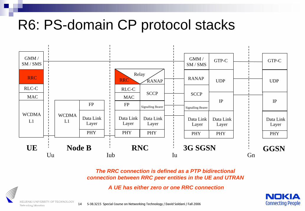
R6: PS-domain CP protocol stacks
Signalling Bearer
PHY
FP
RRC
PHY
WCDMAL1
FP
WCDMAL1
RRC
IubUuRNCNode BUE
RLC-C
MAC
RLC-C
MAC
GMM / SM / SMS
RANAP
SCCP
PHY
3G SGSN
GMM / SM / SMS
Signalling Bearer
RANAP
SCCP
PHY
Iu
Data LinkLayer
Data LinkLayer
Data LinkLayer
Data LinkLayer
RelayUDP
IP
GGSN
GTP-C
PHY
Data LinkLayer
Gn
UDP
IP
GTP-C
PHY
Data LinkLayer
The RRC connection is defined as a PTP bidirectional connection between RRC peer entities in the UE and UTRAN
A UE has either zero or one RRC connection

15 S-38.3215 Special Course on Networking Technology / David Soldani / Fall 2006
UTRA FDD radio interface protocols
L3
cont
rol
cont
rol
cont
rol
cont
rol
Logical Channels
Transport Channels
C-plane signalling U-plane information
PHY
L2/MAC
L1
RLC L2/RLC
MAC
RLC RLC
RLC RLC
RLC RLC
RLC
BMC L2/BMC
control
PDCPPDCP L2/PDCP
Radio Bearers
RRC
16 S-38.3215 Special Course on Networking Technology / David Soldani / Fall 2006
Logical channels (LoCHs)
Define the transfer of a specific type of informationover the radio interfaceThe logical channels are divided into
Control channels (CCH) used for transfer of control plane informationTraffic channels (TCH) used for the transfer of user plane information only

17 S-38.3215 Special Course on Networking Technology / David Soldani / Fall 2006
Transport channels (TCHs)
Specified for data transport between physical layer and Layer 2 peer entitiesTwo types of transport channels exist
Common transport channel (CTCH) is a resource divided between all or a group of users in a cell (in-band ID for users needed)Dedicated transport channel (DTCH) is by definition reserved for a single user

18 S-38.3215 Special Course on Networking Technology / David Soldani / Fall 2006
Physical channels (PhCHs)
Physical channels are defined by a carrier frequency, scrambling code, channelisation code (optional), time duration (start and stop instants) and, in the uplink, relative phase (0 or π/2)A radio frame (38 400 chips = 10 ms) is a processing duration which consists of 15 slots (15 x 2560 chips)A sub-frame (3 slots = 2 ms) is the basic time interval for E-DCH and HS-DSCH transmission and related signaling at the physical layer
19 S-38.3215 Special Course on Networking Technology / David Soldani / Fall 2006
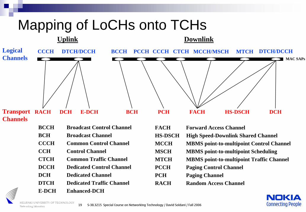
Mapping of LoCHs onto TCHs
BCH PCH FACH DCH
BCCH CCCHPCCH
RACH
Logical Channels
CTCH
DCH
CCCH DTCH/DCCH DTCH/DCCH
Transport Channels
Uplink Downlink
BCCH Broadcast Control ChannelBCH Broadcast ChannelCCCH Common Control ChannelCCH Control ChannelCTCH Common Traffic ChannelDCCH Dedicated Control ChannelDCH Dedicated ChannelDTCH Dedicated Traffic ChannelE-DCH Enhanced-DCH
FACH Forward Access ChannelHS-DSCH High Speed-Downlink Shared ChannelMCCH MBMS point-to-multipoint Control ChannelMSCH MBMS point-to-multipoint SchedulingMTCH MBMS point-to-multipoint Traffic ChannelPCCH Paging Control ChannelPCH Paging ChannelRACH Random Access Channel
HS-DSCHE-DCH
MCCH/MSCH MTCHMAC SAPs

20 S-38.3215 Special Course on Networking Technology / David Soldani / Fall 2006
RRC states in connected mode
Establish RRCconnection
Release RRCconnection
UTRA RRC Connected Mode
URA_PCH CELL_PCH GSM Connected
Mode
Establish RR Connection
Release RR Connection
Idle Mode
Camping on a UTRAN cell Camping on a GSM / GPRS cell
GPRS Packet Idle Mode
GPRS Packet
Transfer Mode
Initiation of temporary block flow
Release of temporary block flow
Cell reselection
out ofservice
inservice
CELL_FACH
out ofservice
inservice
out ofservice
inservice
CS Inter-RAT Handover
PS Handover (3GPP R6)
CELL_DCH
Release RRCconnection
Establish RRCconnection
• BCCH, PCCH• BCH, PCH• URA updates
• DCCH, DTCH• DPCH, HS-DSCH, E-DCH
• BCCH, PCCH• BCH, PCH• Cell updates
• BCCH, PCCH, CTCH/CCCH, DTCH/DCCH• BCH, PCH, FACH, RACH• Cell updates

21 S-38.3215 Special Course on Networking Technology / David Soldani / Fall 2006
TRANSPORT CHANNELSDCH
RACH
BCHFACHPCH
HS-DSCH
E-DCH
Mapping of TCHs onto PhCHsPHYSICAL CHANNELSDedicated Physical Data Channel (DPDCH)Dedicated Physical Control Channel (DPCCH)Fractional Dedicated Physical Channel (F-DPCH)E-DCH Dedicated Physical Data Channel (E-DPDCH)E-DCH Dedicated Physical Control Channel (E-DPCCH)E-DCH Absolute Grant Channel (E-AGCH)E-DCH Relative Grant Channel (E-RGCH)E-DCH Hybrid ARQ Indicator Channel (E-HICH)Physical Random Access Channel (PRACH)Common Pilot Channel (CPICH)Primary Common Control Physical Channel (P-CCPCH)Secondary Common Control Physical Channel (S-CCPCH)Synchronization Channel (SCH)Acquisition Indicator Channel (AICH)Paging Indicator Channel (PICH)MBMS Notification Indicator Channel (MICH)High Speed Physical Downlink Shared Channel (HS-PDSCH)HS-DSCH-related Shared Control Channel (HS-SCCH)Dedicated Physical Control Channel (uplink) for HS-DSCH (HS-DPCCH)

22 S-38.3215 Special Course on Networking Technology / David Soldani / Fall 2006
Example of L2 (MAC)-L1data exchange
TransportBlock Set(TBS) DCH2
T T I
DCH1
T T I
T B
Transport Block
Transport Block
Transport Block
T B
T B
Transmission Time Interval
T T I
T T I
T T I
Transport Format(TF)
Transport Format Set(TFS)
Transport Format Combination(TFC)
Transport Format Combination Set(TFCS)
t
t
HS-DSCH
TB TB TB
T T I T T IT T It
T B T B T B
Transport Block(TB)
T T I = multiple of minimum interleaving
period (10 ms) =10, 20, …,80 ms
T T I = 2 ms

23 S-38.3215 Special Course on Networking Technology / David Soldani / Fall 2006
k:th S-CCPCH
AICH accessslots
SecondarySCH
PrimarySCH
τS-CCPCH,k
10 ms
τPICH
#0 #1 #2 #3 #14#13#12#11#10#9#8#7#6#5#4
Radio frame with (SFN modulo 2) = 0 Radio frame with (SFN modulo 2) = 1
τDPCH,n
P-CCPCH
Any CPICH
PICH for k:thS-CCPCH
Any PDSCH
n:th DPCH
Subframe#0
HS-SCCHSubframes
Subframe#1
Subframe#2
Subframe#3
Subframe#4
τF-DPCH,pp:th F-DPCH
Radio frame and slot timingSlot synchronization
Radio frame synchronization and P-SC
Phase reference for SCH, P/S-CCPCH, AICH and PICH
SFN – Timing ref. for all PhCHs

24 S-38.3215 Special Course on Networking Technology / David Soldani / Fall 2006
R6: Physical layers models – UL1 CCTrCH (RACH) or 2 CCTrCH (RACH + E-DCH)
1 RACH CCTrCH = 1 RACH (no multiplexing)1 E-DCH CCTrCH = 1 E-DCH TrCH, which is carried on the E-DPDCH(s) physical channel(s)
1 HS-DPCCH employed for reporting HS-DSCH transport block acknowledgement (ACK/NACK)Channel Quality Indicator (CQI)
1 E-DPCCH physical channel carriesE-DCH TFCIE-DCH HARQ information

25 S-38.3215 Special Course on Networking Technology / David Soldani / Fall 2006
R6: Physical layers models – DL (1/2)Multiple CCTrCHs can be transmitted simultaneously to one UEPilot, TPC bits and TFCI are time-multiplexed with complex scrambling onto the same dedicated physical channelTPC bits are on F-DPCH(s) for HS-DSCH(s) without a DCHA PCH and one or several FACHs can be encoded and multiplexed together, forming a CCTrCHA PCH is associated with a separate PICHBCH always mapped onto P-CCPCH without any other TCHEach HS-SCCH carries HS-DSCH-related L1 signaling for one UE (i.e., TFRI, HARQ info and UE Id via UE-specific CRC) for each HS-DSCH TTI

26 S-38.3215 Special Course on Networking Technology / David Soldani / Fall 2006
R6: Physical layers models – DL (2/2)E-DCH active set can be ≤ DCH active setE-DCH ACK/NACK are transmitted on E-HICHE-DCH absolute grant is transmitted by the serving E-DCH cell on the E-AGCHE-DCH relative grants can be transmitted on E-RGCH by each cell of the E-DCH active setThere is one serving E-DCH RLS (containing the serving E-DCH cell) and, optionally, one or several non-serving E-DCH radio link(s)For all UE categories, the uplink DCH capability is limited to 64 kb/s when the E-DCH is configured for the radio link

27 S-38.3215 Special Course on Networking Technology / David Soldani / Fall 2006
NGB trafficGB traffic
ConversationalConversational StreamingStreaming InteractiveInteractive BackgroundBackground
AMRLCAMRLC
AMRLCAMRLC
TMRLCTMRLC
DCHDCH
UMRLCUMRLC
DCHDCH
TMRLCTMRLC
DCHDCH
UMRLCUMRLC
DCHDCH
AMRLCAMRLC
DCHDCH RACH/FACHRACH/FACH (E-)DCH/DCH(E-)DCH/DCH(E-)DCH/HS-DSCH(E-)DCH/HS-DSCH
PS domainCS domain
Mapping of bearers onto TCHs

28 S-38.3215 Special Course on Networking Technology / David Soldani / Fall 2006
HSDPA: Fundamental features
Included in HSDPA Excluded from HSDPAEnhanced in HSDPA
Soft Handover
Fast power Control
Variable SF
Adaptive Modulation and Codes
Enhanced Packet
Scheduler
TTI = 2 ms
H-ARQ
Multi-code operation
Basic WCDMA
technology
TF semi-static
attributes

29 S-38.3215 Special Course on Networking Technology / David Soldani / Fall 2006
HSDPA: Radio channels – DL (1/2)HS-DSCH
Defined in R5 and later releases and time/code shared by severalterminalsNo fast PC, but link adaptation by varying effective coding rate (HARQ), number OVSF codes and modulation (QPSK/16QAM)Data channel always associated with a DPCH (or F-DPCH) and one or several HS-SCCHs for related L1 signaling transmissionTF: dynamic part (TB size; redundancy version/constellation; and modulation scheme), static part (TTI = 2ms; turbo-coding 1/3; and CRC = 24 bits)Mapped onto HS-PDSCH
HS-PDSCHData channel with SF = 16, multi-code transmission (up to 15 Walsh or OVSF codes), QPSK or 16QAM modulationTransmitted over the entire cell or over only part of the cell using, e.g. using beam-forming antennas

30 S-38.3215 Special Course on Networking Technology / David Soldani / Fall 2006
HSDPA: Radio channels – DL (2/2)
HS-SCCHFixed-rate physical channel (SF =128) used to carry downlink L1 signaling related to downlink HS-DSCH transmission
UE ID mask, which identifies the user to be served in the next TTITFRI (TB size, modulation scheme and n. of OVSF codes per TTI)HARQ-related information (new data unit or a retransmission that should be combined, associated ARQ process and information about the redundancy version)
HS-SCCH power slow power control (offset relative to the pilot bits of the associated DPCH)

31 S-38.3215 Special Course on Networking Technology / David Soldani / Fall 2006
HSDPA: Radio channels – UL (1/1)
HS-DPCCHFixed-rate (SF 256) used to carry HARQ acknowledgement (ACK/NACK) and channel quality indication (CQI)One HS-DPCCH on each radio linkCan only exist together with an uplink DPCCH for its power control operation, the DPDCH is used as a return channel and user data transmission in UL

32 S-38.3215 Special Course on Networking Technology / David Soldani / Fall 2006
HSDPA: physical layer structureSlot
CQI ACK
Upl
ink
Dow
nlin
k
DL associated DPCH or F-DPCH (for each HSDPA user)
HS-SCCH
HS-PDSCH #1
HS-PDSCH #15
UL associated DPCH (for each HSDPA user)
HS-DPCCH
2ms TTI ∼ 7.5 slots
CQI CQI

33 S-38.3215 Special Course on Networking Technology / David Soldani / Fall 2006
HSDPA: UTRAN end MAC architecture
MA
C-h
s
MACControl
HS-DSCHPr
iorit
y Q
ueue
dist
ribut
ion
Associated Uplink Signalling(HS-DPCCH)
MA
C-d
flow
s
Prio
rity
Que
uePr
iorit
yQ
ueue
Prio
rity
Que
uePr
iorit
yQ
ueue
Flow
Con
tr: M
AC
-sh
and
MA
C-d
To MAC-d flow 1Sc
hedu
ling/
Prio
rity
h
andl
ing
Prio
rity
Que
uedi
strib
utio
n
Associated Downlink Signalling(HS-SCCH)
Max 15 Logical channels per MAC-d flow (UE) using different Channel/Type field (C/T) in MAC-d header, Scheduling Priority Indicator (SPI = 0-15) in NBAP and CmCH-PI in FP using different AAL2 CID
Max 8 priority queues per MAC-d flow and per UE (RRC connection)
HA
RQ
ent
ity
TFR
C se
lect
ion
One per UE (RRC connection)
To MAC-d flow 2

34 S-38.3215 Special Course on Networking Technology / David Soldani / Fall 2006
HSDPA: peer-to-peer communication (1/2)MAC-d PDU (HS-DSCH)
Format equals the format for non HS-DSCH caseMAC PDU (HS-DSCH)
One MAC-hs header One or more MAC-hs SDUs where each MAC-hs SDU equals a MAC-d PDUA maximum of one MAC-hs PDU can be transmitted in a TTI per UEThe MAC-hs header is of variable sizeThe MAC-hs SDUs in one TTI belongs to the same reordering queue

35 S-38.3215 Special Course on Networking Technology / David Soldani / Fall 2006
HSDPA: peer-to-peer communication (2/2)
Queue ID TSN SID1 N1 F1 SID2 N2 F2 SIDk Nk Fk
MAC-hs header MAC-hs SDU Padding (opt)MAC-hs SDU
Mac-hs payload
VF
MAC SDUC/T
MAC-hs PDU
MAC-d PDU
MAC SDUC/T

36 S-38.3215 Special Course on Networking Technology / David Soldani / Fall 2006
HSDPA: adaptive modulation and codingHighest 1st Tx throughputMCS1 is the most spectral efficient allocation
Channelisation Code Capacity (kb/s)
Rec
eive
d D
ata
Bit
E b/N0
(line
ar sc
ale)
0 100 200 300 400 500 600 700 800
0.5
1.5
1
0
2.5
2
3
3.5
4Theoretical Link CapacityLink Level Simulation
Code Efficiency
Pow
er E
ffic
ienc
y
MCS 1(QPSK, ¼)
MCS 2(QPSK, ½)
MCS 3(QPSK, ¾)
MCS4 (16 QAM, ½)
MCS 5 (16 QAM, ¾)
MCS Modulation Effective Coding Rate Bits per TTI
Peak Rate with 1 code (kb/s)
1 1/4 240 120 2 1/2 480 240 3
QPSK 3/4 720 360
4 1/2 960 480 5
16 QAM 3/4 1440 720
700 kb/s x 15 OVSF codes = 10.5 Mb/s

37 S-38.3215 Special Course on Networking Technology / David Soldani / Fall 2006
HSDPA: AMC and multi-code Tx
Higher order MCS when all available codes are used is the most spectral efficient allocation
Opt
imal
num
ber o
f cod
es
-5 0 5 10 15 20 25
Num. available codes ≤ 15Num. available codes ≤ 5
Instantaneous Es/N0 per TTI (dB)
Opt
imal
MC
S
-5 0 5 10 15 20 25
2
1
3
4
5
15
5
0
10

38 S-38.3215 Special Course on Networking Technology / David Soldani / Fall 2006
HSDPA: Link Adaptation (LA)
Channel Quality Indicator (CQI)Reported based on RRC commandsPeriod: 2, 4, 8, 10, 20, 40, 80, 160 ms
Power measurements on associated DL DPCHHARQ Acknowledgement (DL “BLER”)MAC/hs buffer size(Optimal link adaptation functionality makes use of all the above information)

39 S-38.3215 Special Course on Networking Technology / David Soldani / Fall 2006
HSDPA: fast Hybrid ARQStop And Wait (SAW) protocol
One HARQ entity handles the hybrid ARQ functionality for one userTx of current TB until it has been successfully received before initiating Tx of the next oneUp to 8 SAW-ARQ processes may transmit in parallel over different TTIsfor a UE (RRC-connection)
Chase combining (CC)Every retransmission is simply a replica of the coded word employed for the first transmissionThe decoder at the receiver combines these multiple copies of the transmitted packet weighted by the received SNR prior to decoding
Incremental redundancy (IR)Retransmissions include additional redundant information that isincrementally transmitted if the decoding fails on the first attemptThis causes the effective coding rate to increase with the number of retransmissions

40 S-38.3215 Special Course on Networking Technology / David Soldani / Fall 2006
RNC BS
HSDPA: MAC/hs flow control
TS 25.321: Flow control is provided independently by MAC-d flow for a given MAC-hs entity
MAC-hs user data buffer
Flow Control
MAC-d buffer
NBAP: QoS information from RNCDT (Discard Timer)
RNC Control Point
HS-DSCH Data FramePacket
Scheduler
HS-DSCH Capacity Allocation

41 S-38.3215 Special Course on Networking Technology / David Soldani / Fall 2006
HSDPA: flow control mechanism
High threshold
Low threshold
MAC-hs buffer size (per MAC-hs entity)
“High” timer expires
“Low” timer expires
Time
Decrease number of CRedits
Increase number of CRedits

42 S-38.3215 Special Course on Networking Technology / David Soldani / Fall 2006
HSDPA: MAC/hs packet scheduling
For each TTI, PS determines which UE (RRC connection and thus which priority queue), or UEs(code-multiplexing), the HS-DSCH should be allocated to and, in collaboration with the link adaptation mechanism, at what data rateScheduling principles
Radio resources allocated sequentially (round-robin scheduling among RRC connection)Channel and priority dependent scheduling

43 S-38.3215 Special Course on Networking Technology / David Soldani / Fall 2006
HSUPA: Fundamental features
Faster uplinks with lower latency and improves RL efficiency without changing uplink modulationThe main characteristics of HSUPA are
Node B controlled uplink schedulingHARQ protocol between the UE and Node BPossibility of shorter TTI (2 ms) and smaller SF
Effective Coding Rate
User data rate with 1 code (kb/s)
User data rate with 2 codes (Mb/s)
User data rate with 4 codes (Mb/s)
User data rate with 6 codes (Mb/s)
2/3 640 1.28 2.56 3.84 3/4 720 1.44 2.88 4.32 4/4 960 1.92 3.84 5.76

44 S-38.3215 Special Course on Networking Technology / David Soldani / Fall 2006
HSUPA: Radio channels – ULE-DCH
Available in 3GPP R6 and later releasesPossibility of changing rate each TTISupports inner-loop power control and link adaptation by varying the effective coding (HARQ), spreading factor and transmission powerTF: dynamic part (TB size and redundancy version), semi-static part (TTI 2 or 10 ms), static part (turbo-coding 1/3, size of CRC = 24 bits)Mapped onto E-DPDCH
E-DPCHE-DPDCH and E-DPCCH I/Q code-multiplexed with complex scramblingE-DPDCH supports multi-code transmission and SF from 256 down to 2 One E-DPCCH with SF 256 transmits L1 control information associated with E-DCH (E-TFCI = TB size, RSN, happy bit)E-DPCCH is transmitted with a power offset relative to the DPCCH

45 S-38.3215 Special Course on Networking Technology / David Soldani / Fall 2006
HSUPA: Radio channels – DL
E-RGCHFixed-rate physical channel with SF 128 carrying uplink E-DCH relative grants
E-AGCHFixed-rate physical channel with SF 256 carrying uplink E-DCH absolute grants
E-HICHFixed-rate physical channel with SF 128 carrying the uplink E-DCH HARQ acknowledgement indicator

46 S-38.3215 Special Course on Networking Technology / David Soldani / Fall 2006
Node B1
UE
Node B2
Node B3
Cell d3
E-DPDCH(E-DCH) / E-DPCCH (E-TFCI, RSN, Happy bit)DPDCH (CCTrCH) / DPCCH (TFCI, TPC)HS-DPCCH (HARQ ACK/NACK, CQI)
DPDCH / DPCCH
Cell 1, d1, hs, es
Cell e2, d4
Cell e1, d2
DPCH Active Set : Cell d1, d2, d3, d4E-DCH Active Set: Cell es (Serving E-DCH), e1, e2Radio Link Set (RLS): Cell es, e1, d1, d2
DPDCH / DPCCH
E-RGCH (Power: Hold, Down)
E-HICH (ACK/NACK)
DPDCH / DPCCH
E-RGCH (Power: Hold, Down)
E-HICH (ACK/NACK)
HS-SCCH (TFRI, HARQ, UE Id)E-RGCH (Power: UP, Hold, Down)
DPDCH (DCCH) / DPCCH
HS-PDSCH (HS-DSCH)
E-HICH (ACK/NACK)
E-AGCH (Max Power Ratio, E-RNTI)
HSPA: physical layer models

47 S-38.3215 Special Course on Networking Technology / David Soldani / Fall 2006
DCCH
DTCH
DTCH
MAC-d
MA
C-h
s
MAC Control
MA
C-c
MAC-es/e
Associated L1 Uplink Signalling E-TFC (E-DPCCH)
HA
RQ
Pro
cess
es (E
-TFC
, R
SN, P
ower
Off
set)
E-TF
C
Sele
ctio
n
Associated Scheduling DL Signalling (E-AGCH / E-RGCH(s))
Associated ACK/NACK signalling (E-HICH)
C/T
MU
X
DC
H
Uplink User Data / L3 Signalling (E-DCH)
Dec
iphe
ring
C/T
MU
X
UL:
TFC
sele
ctio
n
Cip
herin
g DC
HDTCH
Mul
tiple
of u
p to
15
logi
cal
chan
nels
(8 M
AC
-d fl
ows)
, DD
I an
d TS
N se
tting
Tran
spor
t Cha
nnel
Typ
e Sw
itchi
ng
MA
C-d
Fl
ows
DTCH
Num
berin
gN
umbe
ring
Num
berin
g
Laye
r 1
Laye
r 1
RLC
UE
HSUPA: UE-end MAC architecture

48 S-38.3215 Special Course on Networking Technology / David Soldani / Fall 2006
DCCH
DTCH
DTCH
MAC-d
MAC Control
DTCH
DTCH
MA
C-d
Flows
RLC
DC
H
Deciphering
C/T M
UX
DL Scheduling /
Priority Handling
Ciphering
DC
H
Layer 1
MA
C-hs
MA
C-c
C/T M
UX
/ DL
Priority Setting
FlowC
ontrol
MAC-es/UE
From
MA
C-e in
NodeB
#1
Disassem
bly
Reordering/
Com
bining
From
MA
C-e in
NodeB
#k
MA
C-d flow
#1M
AC
-d flow #n
MAC-e/UE
E-DCH
Associated DLL1 Signaling
(E-HICH)
Associated UL L1 Signaling(E-DPCCH) H
AR
Q Processes
(AC
K/N
AC
K)
E-DC
H
Control
Transport Channel Type Sw
itching
Disassem
bly
Reordering Q
ueue D
istribution Disassem
bly
Reordering/
Com
biningR
eordering/C
ombining
Reordering Q
ueue D
istribution
De-M
UX
SRNC
Node B
Node
B
E-DC
HScheduler
HSUPA: UTRAN-end MAC architecture

49 S-38.3215 Special Course on Networking Technology / David Soldani / Fall 2006
HSUPA: Node B scheduling (1/2)Node B issues scheduling grants to indicate to UE the maximum amount of uplink resources it may use
Control of max E-DPDCH/DPCCH power ratio of active HARQ processesUsed only for E-DCH TFC selection algorithm in the UESent once per TTI or at a slower rate
Absolute grantsE-RNTI of the UE or group of mobiles for which the grant is intendedMax E-DPDCH/DPCCH power ratio (offset) the UE is allowed to useHARQ process activation flag (in case of a 2-ms TTI)
Relative grantsIncrease or decrease the resource limitation (power ratio) compared with the previously used valueFrom serving E-DCH RLS: ‘up’, ‘hold’ or ‘down’From non-serving E-DCH RL: ‘hold’ or ‘down’

50 S-38.3215 Special Course on Networking Technology / David Soldani / Fall 2006
HSUPA: Node B scheduling (2/2)The UE requests resources from BSs in the form of scheduling information and happy bitThe UE is not ‘happy’ when it has power available to send data at higher rates and the total buffer content would require more than X ms to be transmitted with the current SG times the ratio of active processes to the total number of processes (1 for TTI 10 ms)Scheduling information
Sent to the serving E-DCH RLS in a MAC-e PDULogical channel ID of the highest priority channel with data in its bufferUE buffer occupancy: status of the highest priority logical channel with data in its bufferUE power headroom (UPH): ratio of the maximum UE transmission power and the corresponding DPCCH code power

51 S-38.3215 Special Course on Networking Technology / David Soldani / Fall 2006
HSUPA: Non-scheduled transmissionsSRNC may configure the UE for non-scheduled transmissionUE may send data at any time using the E-DCH, without receiving any scheduling command from the Node BNon-scheduled transmissions are defined per MAC-d flowThe resource for non scheduled transmission (non-scheduled grant) is provided by the SRNC in terms of the maximum number of bits that can be included in a MAC-e PDUThe logical channels are served in the order of their priorities until the non-scheduled grant and scheduled grants are exhausted, or the maximum transmit power is reached

52 S-38.3215 Special Course on Networking Technology / David Soldani / Fall 2006
References
D. Soldani, M. Li and R. Cuny (eds.), QoS and QoE Management in UMTS Cellular Systems, John Wiley and Sons, June, 2006, 460 pp.
http://eu.wiley.com/WileyCDA/WileyTitle/productCd-0470016396.htmlhttp://www.connecting.nokia.com/NOKIA/nns.nsf/a/78786C61AB5A7C5AC225718F0026BAA3(contact Mr. Geoff Farrell @ Wiley [email protected] )
See also: http://lib.tkk.fi/Diss/2005/isbn9512278340/