3 phase test separator
TRANSCRIPT

gas stream. The mist extractor—which is the last obstacle the gas must pass before leaving the separator vessel—blocks fine liquid droplets still in the gas.
The blocked droplets coalesce back into the oil phase.
Vessel Capacity
The vessel capacity for each phase depends on the conditions of pressure and temperature and the following:
1. Viscosity and density of the liquid,2. Vessel operating liquid level,3. Vessel internals, such as mist extractors
and coalescing plates,4. Required liquid gas separator efficiency
in terms of size of liquid droplets to be separated from the gas phase, and
5. Size of the vessel itself as shown in the chart below.
Three Phase Test Separator Three Phase Test Separator
he three phase test separator is a mechanical device to separate and measure water, oil and gas rates.
Portable test separators accurately gauge fluid production levels, providing our customers with valuable information regarding the well’s potential and performance.
The main elements of the test separator, which are the vessel (including internal components, pressure and level regulators and safety devices), the piping necessary for the different phases and metering (fitted with corresponding metering devices), and the skid and its protective frame. Separators are also equipped with a built-in shrinkage tester, barton recorder and sampling points.
The principal internal components of the separator are used to help in the separation.
The coalescing plates prevent droplets larger than 15 mm from being carried into the outlet
T
TYPICAL SEPARATOR CAPACITIES
SizeWorking Pressure
(PSI)
Liquid Capacity(barrels/day)
Gas Capacity MMscfd Liquid at 1/3 of the Vessel
400 PSIG 600 PSIG 800 PSIG 1000 PSIG 1200 PSIG 1400 PSIG 2000 PSIG
42" x 10' 1440 10,000 28 35 40 45 50 59 0
42" x 15' 1440 12,000 41 48 53 57 63 72 0
48" x 10' 1440 13,000 42 49 55 60 70 83 0
48" x 15' 1440 19,000 50 58 67 75 82 93 0
48" x 15' 2000 19,000 50 58 67 75 82 93 110
THREE PHASE TEST SEPARATOR
Copyright © 2004 TETRA Technologies, Inc. All rights reserved.TETRA and the TETRA logo are registered trademarks of TETRA Technologies, Inc.
TETRA
PRO
DU
CTIO
N TESTIN
G S
ERV
ICES
November 20083PhTestSepCover
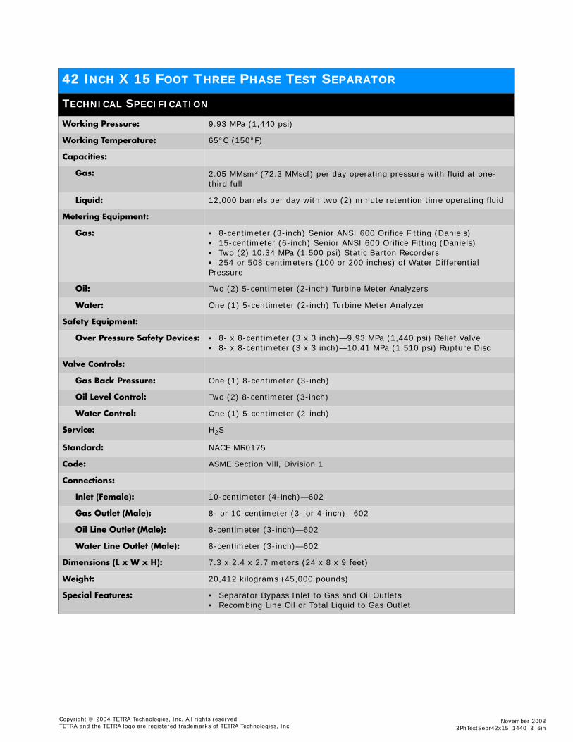
42 INCH X 15 FOOT THREE PHASE TEST SEPARATOR
TECHNICAL SPECIFICATION
Working Pressure: 9.93 MPa (1,440 psi)
Working Temperature: 65°C (150°F)
Capacities:
Gas: 2.05 MMsm3 (72.3 MMscf) per day operating pressure with fluid at one-third full
Liquid: 12,000 barrels per day with two (2) minute retention time operating fluid
Metering Equipment:
Gas: • 8-centimeter (3-inch) Senior ANSI 600 Orifice Fitting (Daniels)• 15-centimeter (6-inch) Senior ANSI 600 Orifice Fitting (Daniels)• Two (2) 10.34 MPa (1,500 psi) Static Barton Recorders• 254 or 508 centimeters (100 or 200 inches) of Water Differential Pressure
Oil: Two (2) 5-centimeter (2-inch) Turbine Meter Analyzers
Water: One (1) 5-centimeter (2-inch) Turbine Meter Analyzer
Safety Equipment:
Over Pressure Safety Devices: • 8- x 8-centimeter (3 x 3 inch)—9.93 MPa (1,440 psi) Relief Valve• 8- x 8-centimeter (3 x 3 inch)—10.41 MPa (1,510 psi) Rupture Disc
Valve Controls:
Gas Back Pressure: One (1) 8-centimeter (3-inch)
Oil Level Control: Two (2) 8-centimeter (3-inch)
Water Control: One (1) 5-centimeter (2-inch)
Service: H2S
Standard: NACE MR0175
Code: ASME Section Vlll, Division 1
Connections:
Inlet (Female): 10-centimeter (4-inch)—602
Gas Outlet (Male): 8- or 10-centimeter (3- or 4-inch)—602
Oil Line Outlet (Male): 8-centimeter (3-inch)—602
Water Line Outlet (Male): 8-centimeter (3-inch)—602
Dimensions (L x W x H): 7.3 x 2.4 x 2.7 meters (24 x 8 x 9 feet)
Weight: 20,412 kilograms (45,000 pounds)
Special Features: • Separator Bypass Inlet to Gas and Oil Outlets• Recombing Line Oil or Total Liquid to Gas Outlet
Copyright © 2004 TETRA Technologies, Inc. All rights reserved.TETRA and the TETRA logo are registered trademarks of TETRA Technologies, Inc.
November 20083PhTestSepr42x15_1440_3_6in