3-phase transformer isolated multi-level inverter using common arm
DESCRIPTION
dc dc convertersTRANSCRIPT

International Conference on Smart Manufacturing ApplicationApril. 9-11, 2008 in KINTEX, Gyeonggi-do, Korea
3-Phase Transformer Isolated Multi-level Inverter Using Common Arm
Song Jiseok, Song Dooyoung, Ju Hongju, Song Sunggun, Kim Dongok, Park SungjunDepartment of Electrical Engineering, Chonnam Nationl University, Gwangju, Korea
(Tel: +82-62-530-0743; E-mail: geeseokghanmail.net)
Abstract: The number of transformer and the size of transformer in inverter using 3-phase transformer could bereduced compare with a multi-level inverter using single phase transformer. But still the 3-phase transformer inverterneeds many switches. In this study, we proposed the isolated multi-level inverter using 3-phase transformers andcommon arm, in this paper. Also, using phase angle control method with switching frequency equal to outputfundamental frequency, harmonics component of output voltage and switching loss can be reduced. Finally, wetested multi-level inverter to clarify electric circuit and reasonableness through Matlab simulation and experiment byusing prototype inverter.
Keywords: H-Bridge, Multi-level inverter, 3-Phase transformer, CHML, Common arm
1. INTRODUCTION
Rcently the research on multi-level inverter has beenreceived a great consideration in industrial field. It has theadvantages of low switching excess loss for its low switchingfrequency, generating high voltage on low switchingfrequency. It is a kind of suitable choice of replacing theexisting PWM inverter.
Commonly multi-level inverter can be clarified into: FlyingCapacitor Circuit (FCC), Diode Clamped Circuit (DCC), andIsolated H-bridge Circuit (IHC). In the IHC type multi-levelinverter the low voltage H-Bridge modules are connected inseries so it is possible to use module that consist dependentDC link cells, but it is the disadvantage that the dependentvoltage need to be provided to each H-Bridge separately. Inorder to overcome shortcomings of IHC inverter, manyresearches on using isolated transformers and single DCsource have been done. In these researches it is necessary ofmany voltage levels for improving the quality of inverteroutput voltage. In case of necessary of many switch elementsand isolated transformers the 3-phase multi-level inverter isapplied.
In this paper, for reducing the number of the transformers,the 3-phase transformers are applied instead of singletransformer. Based on the voltage-piling method the isolated3-phase transformer H-Bridge multi-level inverter (IHCML)has been constructed. In order to reducing the number ofswitch elements in the isolated 3-phase transformer H-Bridgemulti-level inverter a novel common-arm inverter constructionhas been proposed. In the proposed multi-level inverter theswitching frequency is uniformed to the basic frequency byfiring angles control through the same-area-method, THD ofoutput voltage is reduced and the switching loss is decreased.
2.3-PHASE ISOLATED H-BRIDGE MULTI-LEVEL INVERTER
2.1 3-phase IHCML inverterThe structure of 3-Phase IHCML inverter using common-
arm proposed in this paper is shown as figure 1. As shown infigure 1, there are five 3-phase transformers and one DCsource in the IHCML construction. The transformers are lowfrequency type for getting the voltage-piling.
Fig. 1. Structure of 3-Phase IHCML inverter usingcommon-arm
In proposed inverter, for using 3-phase transformers, thenumber of transformers and the volume of system can bereduced and the price of system is deservedly down. Inprimary side of transformers each phase connected by H-Bridges which can generate voltages, and in secondary sideeach phase is connected in serial for piling voltages. Forrestraining unbalanced magnetic composition of 3-phase
538Authorized licensed use limited to: Adhiyamaan College of Engineering. Downloaded on July 27,2010 at 07:26:19 UTC from IEEE Xplore. Restrictions apply.

transformers, each phase is connected in A winding.In IHCML inverter for reducing the output THD the level
should be increased, it means that the same number of switchelements should be increased in the circuit. As shown infigure 3, in the proposed IHCML inverter all firing angles arein the range of and all extinction angles are in the range of,so all polarities of H-Bridges are the same.
As isolated transformers and single DC source are applied,one of the H-Bridge's arms can be connected in common. Asshown in figure 1, the arms that decide the polarity of eachphase are connected in common, 24 switch elements arereduced by this way. If transformers are used in the inverterthe number of reduced switch elements can be calculated as
p = 6(k -1) (1)
In this construction, it can be known that the current oncommon-arm switch element is greater than other arms. Butthe number of switch elements is reduced, so it has theexcellent characteristic on reducing the switching loss.
In figure 2, three transformers are shown. Each phase ofIHCML inverter is expressed as a 3-phase transformer. It canbe known that the input is 3-phase voltage and the output issingle-phase voltage and the outputs are connected in seriesfor piling the voltages.
In figure 1, voltages Vak, Vbk, Vck are the output voltage ofkth H-Bridge and voltages VAk, VBk, Vck are the outputvoltages of each phase of transformers. Therefore the relationbetween input voltage and output voltage of 3-phasetransformer is shown as below.
VAS
CA~~~~A
IHA BC v7 v|~~~~F~ V4sfa
Fig. 2 Simplified structure of 3-Phase IHCML inverter
VAk L2TVBk 1
-VC -I
-1 -1 -Vak-
2 - 1 Vbk- 1 2 -Vck
(2)
Here, T is the transform ratio ( n2 / n1 ) between the 1st sideand the 2ed side of the transformer.
If the input voltage is balanced in three phases, the sum ofall voltages of each phase is 0 as shown below.
Vat + Vbk + V,k 0
expressed the product of the input voltage and the turn ratio oftransformer as below.
VAk Vak
V Bk = T Vbk
VCk _ _ Vck
(4)
But when IHCML inverter is used, because voltages Vak,Vbk, V,k of 1st side of transformer are generated byindependent H-Bridge bringing voltage levels VDC, 0 and -VDC, three phases are often not balanced. So instead offormula (4), formula (2) is usually used. The output voltage ofIHCML inverter is generated by the voltages of transformersconnected in series is able to be expressed by the line voltageVAB, VBC, VCA as shown.
LVAB VAS VA + VA2 + + VAkVBC = VBS = VB1 + VB2 + + VBk (5)
VCA VCS _ VCI + VC2 + + VCk _By using formula (2) and (5), the output voltage of inverter
can be expressed by the output voltage of H-Bridge as shownas below.
IVAB] T
VBC 1
VCA -1Here,
k
V's = E Vjii=l
k
Vbs = Z Vbii=l
k
VCS = vcii=l
1
21
-1 VbS2 ILvs]
(6)
(7)
In the above formula, it means that the inputs oftransformer are connected in series, but actually the outputs ofH-Bridges are all from the same DC source and can not beconnected in series, so the above formula is the virtual sumexpression. It can be known from formula (6) that the linevoltage of 3-phase IHCML may be expressed by the sum ofoutput voltages of each transformer and the sum of the inputvoltage can be controlled by the VaS, VbS, V,S5
2.2 Generating of switching signalWhen five H-Bridges are used for generating the sinusoidalwave output, the output wave of each H-Bridge is shown asfigure 3. Here, the switching frequency is controlled as sameas the basic frequency of the sinusoidal wave.
(3)
From formula (1) and (2), the output voltage is able to be
539Authorized licensed use limited to: Adhiyamaan College of Engineering. Downloaded on July 27,2010 at 07:26:19 UTC from IEEE Xplore. Restrictions apply.

cos( 7a1) + cos( 7a2) + cos( 7a3) +cos( 7a4 ) + cos( 7a5 ) = 0
cos( 11aI) + cos( 11a2) + cos( 11a3) +cos( 11a4) + cos(11a5) = 0
Fig. 3. The switching function ofIHCML inverter
In the inverter, shown as figure 3, according to the firingangles a 2, (3 , 64, (X5 the RMS value of output
voltage is shown as formula (8).
(10)
cos( 13 a) + cos( 13 a2 ) + cos( 13 a3 ) +
cos( 13 a4 ) +cos( 13 a5 0
In the above, m is the modulation index. It is a nonlinearequation that can be solved by the iterative method such asNewton-Rapson method and is impossible to be solved byalgebraic method. But it is impossible to solve the equation atreal time so the pre-calculated modulation index table isapplied. For the continuous control on the firing angle isimpossible the Equal Area method shown as figure 4 is usedto control the firing angle in this paper. The intersect point ofeach level voltage and sinusoidal reference voltage is shownas below.
VO = VDC J-(81Ta 33a2 5ax3 7a4 9a5 ) (8)= sin V; )
As shown in the above formula for the expected RMS outputvoltage, there are not the unique corresponding firing angles
a1' a2 , a6 , a4 , (X5 but there are countless possibility.And for generating a same RMS value, through the firingangle control that can reduce harmonics compositions theTHD of output voltage can be improved. In order to analyzebasic composition and harmonics compositions of the outputvoltage under the firing angles of each inverter the Fourieranalysis is necessary. If the output voltage of inverter is oddfunction, as half-wave symmetry the coefficient of Fourierseries is shown as below.
bn = 4DC [cos( nal ) + cos( na,2) + cos( ncr3)n rT
If the nth junction shown as the formula (11) does not exist,the formula below is used.
(12)IT
n2
By using the intersect point calculated above the firingangles that can uniform the two area shown as figure 4 are
decided by formula below.
°n n -1 V f(VP sin( 0)VDC =
HereI 00 =0
nVdc )o (13)
+ cos( na,4) + cos( na,5)] (9)
Here, n = 1,3,5 1 - 2,1
It can be known that if the output voltage is controlled bythe delay angles a, a2 6(3, 64, 6(5 the basic compositionis generated while the special harmonic compositions are
reduced. In formula above by controlling five delay anglesfour harmonics compositions can be reduced. In 3-phaseinverter, the harmonics compositions in multiple of 3 do notexist. For reducing 5th, 7th, 11th, 13th harmonic compositionsthe formula that decides that firing angles are shown as below.
cos( a ,) + cos( a 2) + cos( a ,) +
cos( a4 ) + cos( a 5)5m z
4
cos( 5a1) + cos( 5cr2)+ cos( 5cr3) +
cos(54 ) +cos(55) O
Vt
Fig. 4. The principle of conduction angle determination forTHD reduction
3. SIMULATIONS AND RESULTS
To verify the validity of proposed IHCML inverter, thesimulation in Matlab and the experiment using a prototypeinverter in Lab have been done. The input voltage is set to1OOV and the transformer ratio is set to 1. When modulationindex is 1.0 the output voltage of each H-Bridge, the referencevoltages using Equal-Area method and virtual output voltageare shown as figure 5. It is obvious that the frequency of eachswitch and basic frequency is same.
540
(11)
I,
7= -1-L- ..L
A. L--J----IS V-1-F- P.-r ai V.Z
A
P
i. V-, A
--I-A p-
f.I 7L,
..7iIxri I I
I 11
°oi
i
i
t
i
i
_ i-H
Authorized licensed use limited to: Adhiyamaan College of Engineering. Downloaded on July 27,2010 at 07:26:19 UTC from IEEE Xplore. Restrictions apply.

r .......r........ .......r................ .......
iLo Rf 'iO a0f AO O L2 & o
Fi.5.HBideouptanrernc vltg onmduaio
{wj l 1~~~~~~~LA
Fig. 6. Transformer and inverter output voltage onmodulation 1.0
When modulation index is 1.0, A-phase output voltage ofeach 3-phase transformer, the reference voltages and finaloutput voltage of inverter generated by piling transformervoltages are shown as figure 6. It can be known that thougheach phase input is rectangular wave but the output is like thewave shown as figure base on the formula (2). It can be knowfrom the figure that the basic composition and polarity ofoutput voltage in each transformer are all same and the phaseand polarity have no change despite connecting transformersin series. It is also obvious that the final output voltage ofinverter can follow the reference voltage very well.
.XX
g M /E~
Fig. 7. Output voltage THD and DF for differentmodulation
When the formula (10) is used to solve the result ofnonlinear equation THD and DF of output voltage accordingto the firing angles calculated by the Newton-rapson methodare shown as figure 7. It can be known that 2 results are
approximately same and the DF of current is under 5°0 whenthe modulation index is over 0.3.As shown in figure 8 the proposed prototype inverter is madeand tested to clarify the reasonableness of the proposed 3-phase IHCML inverter by using five 3-phase transformers andsix IPMs in the Lab. The processor is DSP 2812 and the IQ-math of TI is used to calculate the firing angles and junctionangles on-line. For controlling many switches the 2-level latchcircuit is used to generate the dead time and the control signalsare synchronous.
Fig. 8. Prototype 3-Phase IHCML inverter
When the modulation index is 1.0 the reference voltage andoutput voltage of each H-Bridge in experiment are shown asfigure 9. As same as simulation result it can be known that alloutput polarities are same and the frequency of each switchingis equal to the basic frequency.
Ch3F7 R7q77 dh'4r I v= |~ .3 12W20k2idg 21;41 .26
Fig. 9. The output voltage of H-Bridge and referencevoltage
31-,[ +7b +7Ti F4+ 17,
ml+T+h
1n-+T)
5ttV A :_. v 22hFig. 10.Theoutputvoltageofeach3-phasetransform23e0r;21
Fig. 10. The output voltage of each 3-phase transformer
541
""I -
0 L..L. --l"wlo. ;....."'IT----,....i
*IF'W Di-t1
lAl PRevuSfPs
x
Authorized licensed use limited to: Adhiyamaan College of Engineering. Downloaded on July 27,2010 at 07:26:19 UTC from IEEE Xplore. Restrictions apply.
U0 13 12W2J0(b)
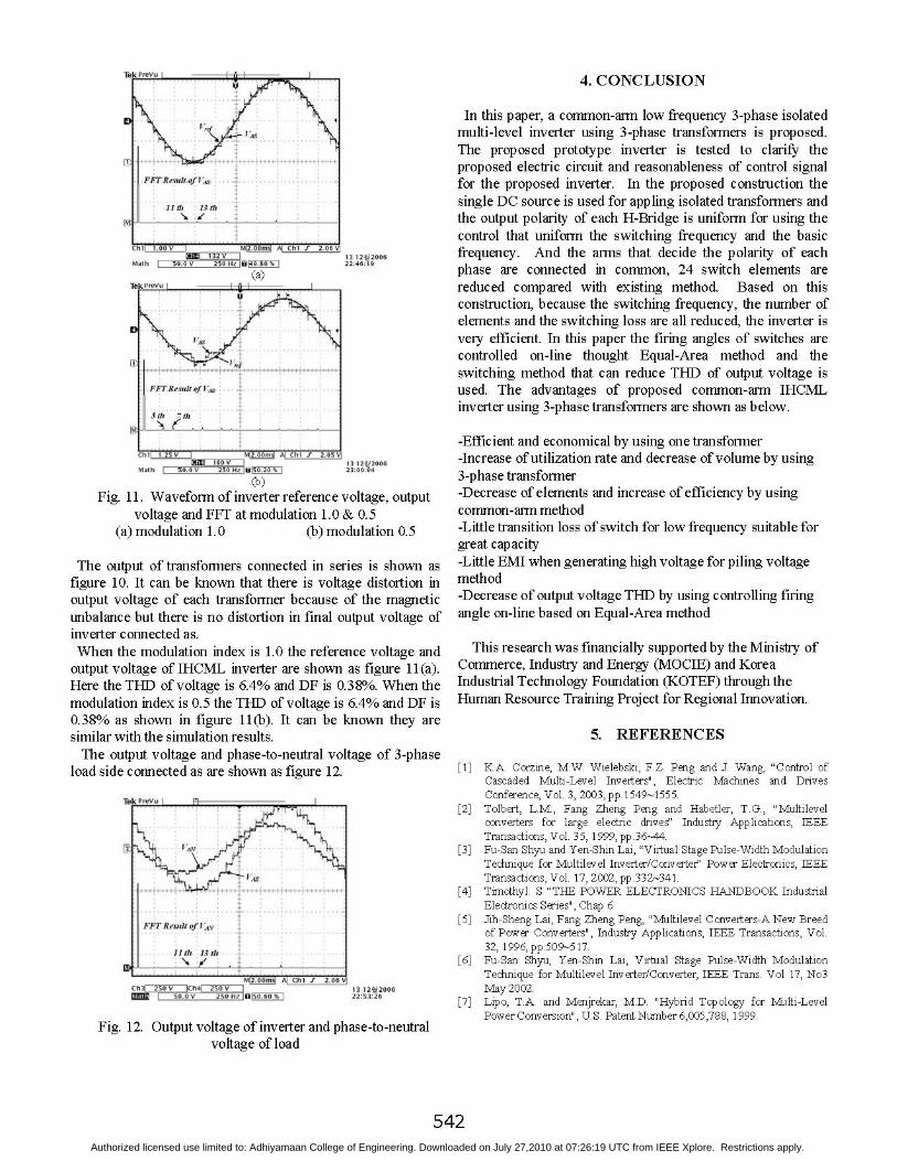
Fig. 11. Waveform of inverter reference voltage, outputvoltage and FFT at modulation 1.0 & 0.5
(a) modulation 1.0 (b) modulation 0.5
The output of transformers connected in series is shown asfigure 10. It can be known that there is voltage distortion inoutput voltage of each transformer because of the magneticunbalance but there is no distortion in final output voltage ofinverter connected as.When the modulation index is 1.0 the reference voltage and
output voltage of IHCML inverter are shown as figure 11(a).Here the THD of voltage is 6.4% and DF is 0.38%. When themodulation index is 0.5 the THD of voltage is 6.4% and DF is0.38% as shown in figure 11(b). It can be known they aresimilar with the simulation results.The output voltage and phase-to-neutral voltage of 3-phase
load side connected as are shown as figure 12.
Ii V 4 .6V
Fig. 12. Output voltage of inverter and phase-to-neutralvoltage of load
4. CONCLUSION
In this paper, a common-arm low frequency 3-phase isolatedmulti-level inverter using 3-phase transformers is proposed.The proposed prototype inverter is tested to clarify theproposed electric circuit and reasonableness of control signalfor the proposed inverter. In the proposed construction thesingle DC source is used for appling isolated transformers andthe output polarity of each H-Bridge is uniform for using thecontrol that uniform the switching frequency and the basicfrequency. And the arms that decide the polarity of eachphase are connected in common, 24 switch elements arereduced compared with existing method. Based on thisconstruction, because the switching frequency, the number ofelements and the switching loss are all reduced, the inverter isvery efficient. In this paper the firing angles of switches arecontrolled on-line thought Equal-Area method and theswitching method that can reduce THD of output voltage isused. The advantages of proposed common-arm IHCMLinverter using 3-phase transformers are shown as below.
-Efficient and economical by using one transformer-Increase of utilization rate and decrease of volume by using3-phase transformer-Decrease of elements and increase of efficiency by usingcommon-arm method-Little transition loss of switch for low frequency suitable forgreat capacity-Little EMI when generating high voltage for piling voltagemethod-Decrease of output voltage THD by using controlling firingangle on-line based on Equal-Area method
This research was financially supported by the Ministry ofCommerce, Industry and Energy (MOCIE) and KoreaIndustrial Technology Foundation (KOTEF) through theHuman Resource Training Project for Regional Innovation.
5. REFERENCES
[1] K.A. Corzine, M.W. Wielebski, F.Z. Peng and J. Wang, "Control ofCascaded Multi-Level Inverters", Electric Machines and DrivesConference, Vol. 3, 2003, pp.1549 1555.
[2] Tolbert, L.M., Fang Zheng Peng and Habetler, T.G., "Multilevelconverters for large electric drives" Industry Applications, IEEETransactions, Vol. 35, 1999, pp.36-44.
[3] Fu-San Shyu and Yen-Shin Lai, "Virtual Stage Pulse-Width ModulationTechnique for Multilevel Inverter/Converter" Power Electronics, IEEETransactions, Vol. 17, 2002, pp.332-341.
[4] Timothyl. S "THE POWER ELECTRONICS HANDBOOK IndustrialElectronics Series", Chap 6
[5] Jih-Sheng Lai, Fang Zheng Peng, "Multilevel Converters-A New Breedof Power Converters", Industry Applications, IEEE Transactions, Vol.32, 1996, pp.509 517.
[6] Fu-San Shyu, Yen-Shin Lai, Virtual Stage Pulse-Width ModulationTechnique for Multilevel Inverter/Converter, IEEE Trans. Vol 17, No3May 2002.
[7] Lipo, T.A. and Menjrekar, M.D. "Hybrid Topology for Multi-LevelPower Conversion", U.S. Patent Number 6,005,788, 1999.
542Authorized licensed use limited to: Adhiyamaan College of Engineering. Downloaded on July 27,2010 at 07:26:19 UTC from IEEE Xplore. Restrictions apply.